Separation of Arc Plasma and Current in Electrical Arc ... · Separation of Arc Plasma and Current...
9
Introduction Through developments in science and technology, newer welding meth- ods such as laser beam welding (Ref. 1), friction stir welding (Ref. 2), and magnetic pulse welding (Ref. 3) have been developed and applied in manu- facturing. However, to date, arc weld- ing is still the most widely used process for metal joining. Since Vasily Petrov discovered the phenomenon of continuous electrical discharge in 1802 and scientists subsequently pro- posed its practical applications for welding (Ref. 4), through developments in power sources and welding materials, a large number of arc welding processes/variants have been invented. Arc welding processes have played and are expected to continue playing an irreplaceable role in metals joining. A welding arc delivers the density and distribution of current, heat flow, and pressure needed for welding on the surface of the weld pool where the complex welding phenomena originate. It plays the most critical role in determining how the welding is per- formed, how the weld is made, if qual- ity welds are made, and how fast qual- ity welds are made. Improved understanding about the physics of the welding arc may lead to improved processes, designs, productivity, and quality. While many researchers have focused on micro scales, including studies on arc column temperature measurement using spectroscopes (Refs. 5–7) and probes (Ref. 8), on cathode spots (Ref. 9), and on energy distribution (Refs. 10, 11), some have studied on macro scales, whose subjects of study include voltage-arc length relationship (Ref. 12), voltage- current relationship (Ref. 13), and arc reignition and stability (Ref. 14). Other researchers are working on mesoscopic scales with interests in electrons and plasma flow. References exist that define welding arcs (Refs. 15–17). In particu- lar, Ref. 15 gives the definition that “a welding arc is a particular group of electrical discharges that are formed and sustained by the development of a gaseous conduction medium.” The arc current follows through the arc plasma, “the ionized state of a gas composed of nearly equal numbers of electrons and ions of gas atoms and molecules.” It is clear that due to the small mass and high mobility, electrons that emit from the cathode WELDING RESEARCH JULY 2014 / WELDING JOURNAL 253-s Separation of Arc Plasma and Current in Electrical Arc — An Initial Study The arc plasma and the electron flow that ionized the gas to form the arc plasma were separated, proving separability is a property of the welding arc S. J. CHEN, F. JIANG, Y. S. LU, AND Y. M. ZHANG ABSTRACT The authors consider a welding arc as a composite of an electron flow and electrically neutral arc plasma consisting of equal numbers of ions and elec- trons. In normal welding conditions, the arc plasma and electron flow are merged forming an arc of classical definition. In this paper, the arc plasma and the electron flow that ionized the gas to form the arc plasma are consid- ered separable. To demonstrate the arc separation phenomena, this initial study deviates the anode from the tungsten axis both for the constrained plasma arc (PA) and unconstrained free gas tungsten arc (GTA) to deviate the electron flow. An interference gas flow is also applied as an external force to deviate the arc plasma whose initial speed is approximately along the tungsten arc axis. The observed phenomena are qualitatively analyzed to show that separability is indeed a property of the welding arc. A simplified preliminary theoretical analysis shows arc separability is determined by the initial speed of the arc plasma, which in turn depends on the welding parameters. While the primary concern of this initial study is to disclose only in qualitative ways that the arc can be separated into the arc plasma and electron flow, it is also the intent of the authors to quantitatively study the separation in the future as well as to separate arcs for specific application needs. KEYWORDS • Arc • Plasma • Electron Flow • Gas Tungsten Arc Welding (GTAW) • Plasma Arc Welding (PAW) • Separation • Separability • Arc Stiffness S. J. CHEN ([email protected]), F. JIANG, and Y. S. LU are with the Welding Research Institute, Beijing University of Technology, China. Y. M. ZHANG is with the Institute for Sustainable Manufacturing and Department of Electrical and Computer Engineering, University of Kentucky, Lexington, Ky.
Transcript of Separation of Arc Plasma and Current in Electrical Arc ... · Separation of Arc Plasma and Current...
Introduction
Through developments in scienceand technology, newer welding meth-ods such as laser beam welding (Ref.1), friction stir welding (Ref. 2), andmagnetic pulse welding (Ref. 3) havebeen developed and applied in manu-facturing. However, to date, arc weld-ing is still the most widely usedprocess for metal joining. Since VasilyPetrov discovered the phenomenon of
continuous electrical discharge in1802 and scientists subsequently pro-posed its practical applications forwelding (Ref. 4), throughdevelopments in power sources andwelding materials, a large number ofarc welding processes/variants havebeen invented. Arc welding processeshave played and are expected tocontinue playing an irreplaceable rolein metals joining. A welding arc delivers the density
and distribution of current, heat flow,and pressure needed for welding onthe surface of the weld pool where thecomplex welding phenomenaoriginate. It plays the most critical rolein determining how the welding is per-formed, how the weld is made, if qual-ity welds are made, and how fast qual-ity welds are made. Improvedunderstanding about the physics ofthe welding arc may lead to improvedprocesses, designs, productivity, andquality. While many researchers havefocused on micro scales, includingstudies on arc column temperaturemeasurement using spectroscopes(Refs. 5–7) and probes (Ref. 8), oncathode spots (Ref. 9), and on energydistribution (Refs. 10, 11), some havestudied on macro scales, whosesubjects of study include voltage-arclength relationship (Ref. 12), voltage-current relationship (Ref. 13), and arcreignition and stability (Ref. 14).Other researchers are working onmesoscopic scales with interests inelectrons and plasma flow. References exist that definewelding arcs (Refs. 15–17). In particu-lar, Ref. 15 gives the definition that “awelding arc is a particular group ofelectrical discharges that are formedand sustained by the development of agaseous conduction medium.” The arccurrent follows through the arcplasma, “the ionized state of a gascomposed of nearly equal numbers ofelectrons and ions of gas atoms andmolecules.” It is clear that due to thesmall mass and high mobility,electrons that emit from the cathode
WELDING RESEARCH
JULY 2014 / WELDING JOURNAL 253-s
Separation of Arc Plasma and Current in Electrical Arc — An Initial Study
The arc plasma and the electron flow that ionized the gas to form the arc plasma wereseparated, proving separability is a property of the welding arc
S. J. CHEN, F. JIANG, Y. S. LU, AND Y. M. ZHANG
ABSTRACT The authors consider a welding arc as a composite of an electron flow andelectrically neutral arc plasma consisting of equal numbers of ions and elec-trons. In normal welding conditions, the arc plasma and electron flow aremerged forming an arc of classical definition. In this paper, the arc plasmaand the electron flow that ionized the gas to form the arc plasma are consid-ered separable. To demonstrate the arc separation phenomena, this initialstudy deviates the anode from the tungsten axis both for the constrainedplasma arc (PA) and unconstrained free gas tungsten arc (GTA) to deviatethe electron flow. An interference gas flow is also applied as an externalforce to deviate the arc plasma whose initial speed is approximately alongthe tungsten arc axis. The observed phenomena are qualitatively analyzed toshow that separability is indeed a property of the welding arc. A simplifiedpreliminary theoretical analysis shows arc separability is determined by theinitial speed of the arc plasma, which in turn depends on the weldingparameters. While the primary concern of this initial study is to discloseonly in qualitative ways that the arc can be separated into the arc plasmaand electron flow, it is also the intent of the authors to quantitatively studythe separation in the future as well as to separate arcs for specificapplication needs.
KEYWORDS • Arc • Plasma • Electron Flow • Gas Tungsten Arc Welding (GTAW) • Plasma Arc Welding (PAW) • Separation • Separability • Arc Stiffness
S. J. CHEN ([email protected]), F. JIANG, and Y. S. LU are with the Welding Research Institute, Beijing University of Technology, China. Y. M. ZHANG is withthe Institute for Sustainable Manufacturing and Department of Electrical and Computer Engineering, University of Kentucky, Lexington, Ky.
Final Chen Layout_Layout 1 6/13/14 10:25 AM Page 253
to move to the anode count for theflow of the charges. However, there isa shortage of details on how the arcplasma and current flow would behaveif the arcing conditions are subject tochanges from typical. In traditional welding arc theory(Refs. 18–24), the welding current (ac-tually the electron flow) is carried bythe arc plasma and keeps it ionized.Based on Lancaster (Ref. 18), “The in-teraction of the current and its self-induced magnetic field results inforces that induce plasma flow fromthe electrode towards the plate.” Acommon understanding may thus bethat the arc has a certain quality ofstiffness to retain its shape such thatit is relatively inflexible and difficult tobend. It is true that, when theelectrode points in a particular direc-tion, the arc would tend to point tothat same direction. However, as theauthors experimentally observed anddemonstrate in this initial study, morecomplex phenomena occur in theabsence of such ideal arcing conditionswhen the anode is deviated from thedirection pointed to by the electrode. To explain such experimentally ob-served phenomena, the authorspropose to clearly and intentionallyconsider the following: 1) the weldingarc is a composite of two physical bod-ies, the arc plasma and currentflow/electron flow, and 2) these twobodies are separable under a certaincondition. For convenience of discus-sion, the authors propose separabilityas a property of the welding arc. As isdemonstrated in this paper, with theseparability, certain phenomenaobserved in the absence of ideal arcingconditions may be effectivelyexplained. As developments of novelarc welding processes such as hybridlaser-arc welding (Refs. 25, 26) and
double-electrode arc welding (Refs. 27,28), ideal arcing conditions as in tradi-tional “single electrode to workpiece”arc welding processes may not alwaysbe kept. In this regard, an intentionaluse of separability as a property of thewelding arc may help the developmentand understanding of innovative arcwelding processes.
Separability
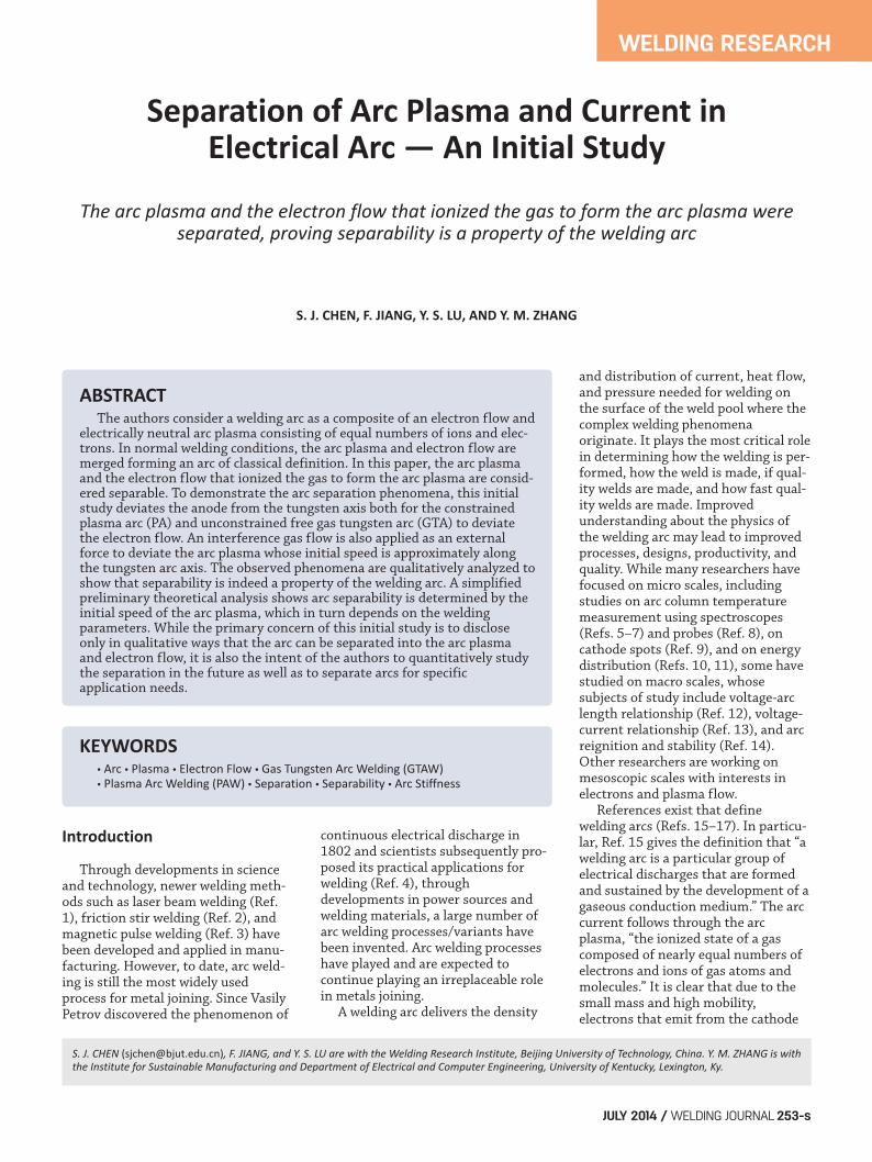
Per the arc minimum voltage prin-ciple (Steenbeck’s minimum principle)(Ref. 29), the arc column keeps theminimum electric field strength. Thisimplies that the arc has the propertyto minimize energy consumption.When the anode deviates from theaxis of the tungsten cathode, it is com-monly believed that the arc alwaysfinds the shortest path from the cath-ode to the anode. However, the obser-vations from the followingexperiments present a challenge if onewould still try to apply the minimumvoltage principle directly withoutkeeping possible constraints in mind.With separability, these observationscan be easily explained. Figure 1A illustrates the experimen-tal principle. This is plasma arc welding
(PAW) or gas tungsten arc welding(GTAW) without filler metal but hasbeen modified such that the typicalworkpiece anode is replaced with ananode deviated from the tungsten axis.The deviated distance is 6 mm asmarked in Fig. 1A. The anode is a water-cooled copper block. Figure 1B showsthe behavior of a gas tungsten arc under120-A current and 4-mm tungsten eval-uation above the anode. Figure 1C is thebehavior of a plasma arc under 80-Acurrent, 3.0-L/min plasma gas flow rate,3-mm orifice diameter, 4-mm tungstensetback, and 6-mm tungsten evaluationabove the anode. When the classical arc minimumvoltage principle is directly appliedwithout constraints, a bright area(Zone A in Fig. 2) should be expectedwhere A stands for the arc. However,in addition to Zone A, Zone IG is alsoobserved as can be seen in Fig. 1B, Cwhere IG stands for the ionized gas.The questions that need to beanswered here are why Zone IG is alsoobserved and what are Zones A and IGand how the minimum arc voltageprinciple should be applied.
WELDING RESEARCH
WELDING JOURNAL / JULY 2014, VOL. 93254-s
Fig. 1 — Anode deviation experiments. A — Experimental principle; B — gas tungsten arc; C — plasma arc.
Fig. 2 — Illustration of a separated arc. Fig. 3 — Free jet experimental setup. Theelevation of the tungsten above theanode surface was 6 mm. The left surface was 6 mm from the tungsten arc axis.
A B C
Final Chen Layout_Layout 1 6/13/14 10:26 AM Page 254
The authors would argue that ZoneA is an arc (arc composite) where thearc plasma and electron flow coexistand Zone IG is a pure arc plasma bodyformed only by the ionized gas inwhich there is no current/electronflow. To understand this, one can con-sider the shielding gas and the plasmagas as a gas flow from the nozzleand/or orifice approximately along thetungsten axis direction with certain di-vergence, especially in GTAW. The gasflow is first ionized around the tung-sten tip. The ionized gas itself is stillelectrically neutral, and its inertia inthe direction of the gas flow from thenozzle/orifice is unchanged. If there isno deviation in the anode, suchionized gas will flow together with theelectron flow in the same directionand be continuously ionized by theelectron flow. With the anodedeviation, the electric field directiondeviates toward the deviated anodefrom the direction of the ionized gas
(arc plasma) flow. Due to the inertia,the arc plasma will continue flowingforming Zone IG, which consistspurely of ionized gas. The electronswith the trajectory toward the anodewill form Zone A. In Zone A,previously unionized gas iscontinuously ionized gradually alongthe trajectory toward the anode. As aresult, under a deviated anode, the arcis of classical definition. In such a clas-sical definition of an arc, the electronflow shares the trajectory with theelectrically neutral arc plasma; suchelectrically neutral arc plasma was theresult of the earlier ionization causedby the electron flows. The electronflow continuously maintains the ion-ization of this arc plasma previouslyionized by it has been changed into 1)an electrically neutral arc plasma thathas been separated from the electronsthat ionized it — Zone IG; and 2) anarc in which the electron flow continu-ously ionizes a significant amount of
the fresh shielding gas that was notionized earlier in addition to maintain-ing the ionization to the previouslyionized arc plasma — Zone A. Inshort, Zone A is an arc where the elec-tron flow and ionized plasma are bothpresent but a significant amount offresh gas is also ionized. Zone IG is anionized gas body from which itsionization electron flow is separated.Zone IG is bright in the image becauseits temperature is still high. The above analysis leads to the fol-lowing statement about a property ofthe welding arc that is referred to asthe arc separability in this paper.
Arc Separability
The ionized electrically neutral arcplasma and the electron flow in an arc(arc composite) may be spatially physi-cally separated forming their owntrajectories. Of course, after separation, the
WELDING RESEARCH
JULY 2014 / WELDING JOURNAL 255-s
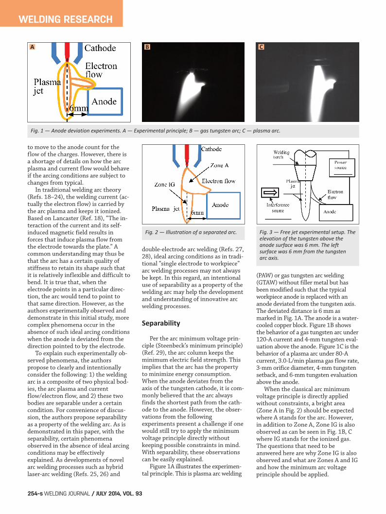
Fig. 5 — Deviated anode experiment with disturbance gas for constrained PA in Experiment 1. A — PAW arc without disturbance; B — PAW arc with disturbance.
Fig. 6 — Deviated anode experiment with disturbance gas for unconstrained free GTA inExperiment 2. A — GTAW arc without disturbance; B — GTAW arc with disturbance.
Fig. 4 — Welding experimental setup.The upper surfaces of the neutral andanode copper blocks are at the samelevel. The elevation of the tungstenabove their upper surface varies in theexperiments. The left surface of theanode block is 8 mm from the tungstenaxis. The gap between the blocks is 1mm. A — Separated arc mode, the contactor is disconnected; B — compositedarc mode, the contactor is connected.
A A
B
B
A B
Final Chen Layout_Layout 1 6/13/14 10:25 AM Page 255
electron flow will have to ionize freshgas to continue its trajectory towardthe anode forming “newly born” arcplasma. The arc formed by theelectron flow and this newly born,electrically neutral arc plasma shouldstill satisfy the minimum arc voltageprinciple. However, the arc plasmaafter the separation of the electronflow is electrically neutral and is nolonger an arc. The minimum voltageprinciple thus does not apply to it. Separability is a property of thewelding arc that can be wellunderstood and explained using exist-ing knowledge/theory. This paper ex-perimentally demonstrates this prop-erty, applies it to explain experimentalobservations, and establishes the the-oretical foundation to analyze and un-derstand the separation as a physicalprocess. To this end, additional experi-ments were conducted.
Experimental Procedure
Experimental Setup
Two types of arcs were involved inthis study: separated arc and compos-ited arc. Two types of experiments
were conducted using the setups illus-trated in Figs. 3 and 4. One was thefree jet experimental setup, tocompare the free jet in GTA and PA, asshown in Fig. 3, and the type of arcwas a separated arc. This setupconsisted of a welding torch, a water-cooled copper block, and aninterference source. The torch was ver-tically fixed on a test stand; itsposition could be adjusted three-dimensionally. The water-cooled cop-per block used as the anode was placedhorizontally 6 mm away from thetorch/tungsten axis. Its left surfacewas coated with ceramic for insulation.A GTAW torch or PAW torch was usedto produce unconstrained free GTA orconstrained PA. The power source waschosen based on the torch (GTAW orPAW) used. An external disturbanceargon gas flow was used as theinterference source to apply an exter-nal force on the electrically neutral arcplasma. Another experimental setup,referred to as the welding experimen-tal setup, was designed to simulate thereal welding condition. There were twoworking modes in this setup toprovide a separated arc or composited
arc. The first was the separated arcmode, shown in Fig. 4A, in which an-other water-cooled copper block wasadded with a narrow gap with theanode water-cooled copper block. Itwas electrically neutral and insulatedfrom the anode block by a ceramiccoating on the facing surface of bothblocks. A high-power DC contactorwas used to electrically connect thetwo copper blocks for easy arc ignitionand when needed for conducting com-parison experiments without anodedeviation but still with interference. Inthe separated arc mode, as shown inFig. 4B, the contactor wasdisconnected to provide a separatedarc. The second mode was the compos-ited arc mode. Here the contactor wasconnected with the same setup, so thetwo water-cooled copper bocks wereelectrically connected to provide thecomposited arc.
Experimental Procedure
Experimental Setup
An external disturbance gas flowwas used as an interference to affectthe plasma jet and electron flow. Pureargon with a flow rate of 12 L/min wasused as the shielding gas in all experi-ments. The disturbance gas flow (pureargon) was applied using a 6-mm-IDcopper pipe, when interference wasneeded, perpendicular to the tungstenat the middle of the arc. The distancefrom the pipe outlet to the tungstenaxis was 20 mm. Table 1 lists themajor parameters for the designed ex-periments. An ultrahigh shutter speedvision system was used to image thearc and arc plasma in all of the experi-ments. The arc types and setup typesin Table 1 are defined below.
WELDING RESEARCH
WELDING JOURNAL / JULY 2014, VOL. 93256-s
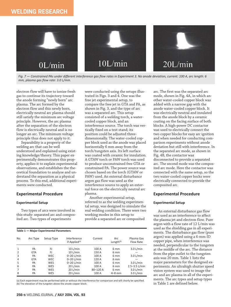
Fig. 7 — Constrained PAs under different interference gas flow rates in Experiment 3. No anode deviation, current: 100 A, arc length: 6mm, plasma gas flow rate: 3.0 L/min.
Table 1 — Major Experimental Parameters
No. Arc Type Setup Type Interference Current Arc Plasma Gasif Applied(a) Length(b) Flow Rate
1 PA FJ 10 L/min 100 A 6 mm 3.0 L/min2 GTA FJ 10 L/min 150 A 6 mm —3 PA WEC 0–20 L/min 100 A 6 mm 3.0 L/min4 GTA WEC 0–20 L/min 120 A 6 mm —5 PA WES 0–20 L/min 100 A 6 mm 3.0 L/min6 PA WES 20 L/min 100 A 6 mm 2.5–3.5 L/min7 PA WES 20 L/min 80–120 A 6 mm 3.0 L/min8 PA WES 20 L/min 100 A 4–8 mm 3.0 L/min
(a) Each experiment may be performed with or without the interference for comparison and will clearly be specified. (b) The elevation of the tungsten above the anode copper block.
Final Chen Layout_Layout 1 6/13/14 10:25 AM Page 256
GTA: Gas tungsten arc, which wasprovided by a GTAW torch and powersource, as a comparison with plasmaarc. PA: Plasma arc, which was providedby a PA torch and power source. FJ: Free jet experimental setup, asshown in Fig. 3. This experimentalsetup provided a separated arc. The arcplasma could move freely withoutblockage. WES:Welding experimental setupworking in separated arc mode, asshown in Fig. 4A. This experimentalsetup provided a separated arc and hada water-cooled copper block to replacethe workpiece in normal welding condition. This simulates the realwelding condition except for the anode deviation. WEC:Welding experimental setupworking in composited arc mode (nor-mal welding arc mode), as shown inFig. 4B. This experimental setupprovided a composited arc as innormal welding except that the workpiece was replaced by a water-cooled copper block.
Experimental Results and Analysis
Arc Constraint
Experiments 1 and 2 were designedto examine the effect of arc constrainton separability. While the arc in Exper-iment 1 was constrained PA, the arc inExperiment 2 was free GTA withoutconstraint. In both experiments, theanode was deviated. When there wasno interference gas, as can be seenfrom Figs. 5A and 6A, the deviatedanode caused the separation resultingin distinguishable Zones A and IG forboth constrained PAW and
unconstrained free GTA. However,after the interference gas was applied,for the arc without constraint inExperiment 2, the arc separation wasno longer distinguishable, as can beseen in Fig. 6B. On the other hand, de-spite the applied interference gas, thearc separation observed in Fig. 5A wasstill similarly distinguishable in Fig.5B. From this point of view, aconstraint on the arc enhanced the arcseparation. In particular, in Experiment 1 forthe constrained PA, the direction ofthe arc plasma (Zone IG in Fig. 2) wasnot significantly changed except for aslight reduction in length. Further, theshape of the composite arc (Zone A inFig. 2) was similar for both with andwithout the interference gas. The be-havior of the separation remained ap-proximately unchanged. However, inExperiment 2 for the free GTA withoutconstraint, Zones A and IG are clearlypresent in Fig. 6A without an interfer-ence gas. After the interference gaswas applied, as can be seen in Fig. 6B,Zones A and IG were approximatelymerged and became indistinguishable.While Zone A was not affected, the di-rection of Zone IG changed toward thedeviated anode. The flexibility of thearc plasma without constraint helpedprevent the arc from separating.
Interference
In this group of experiments, theinterference gas was applied at threedifferent rates — zero, 10, and 20L/min — in each of the experiments. Figure 7 shows the results from Ex-periment 3 for constrained PA under100-A current, 6-mm arc length, and3.0 L/min plasma gas flow rate. In thisexperiment, the neutral block in setup
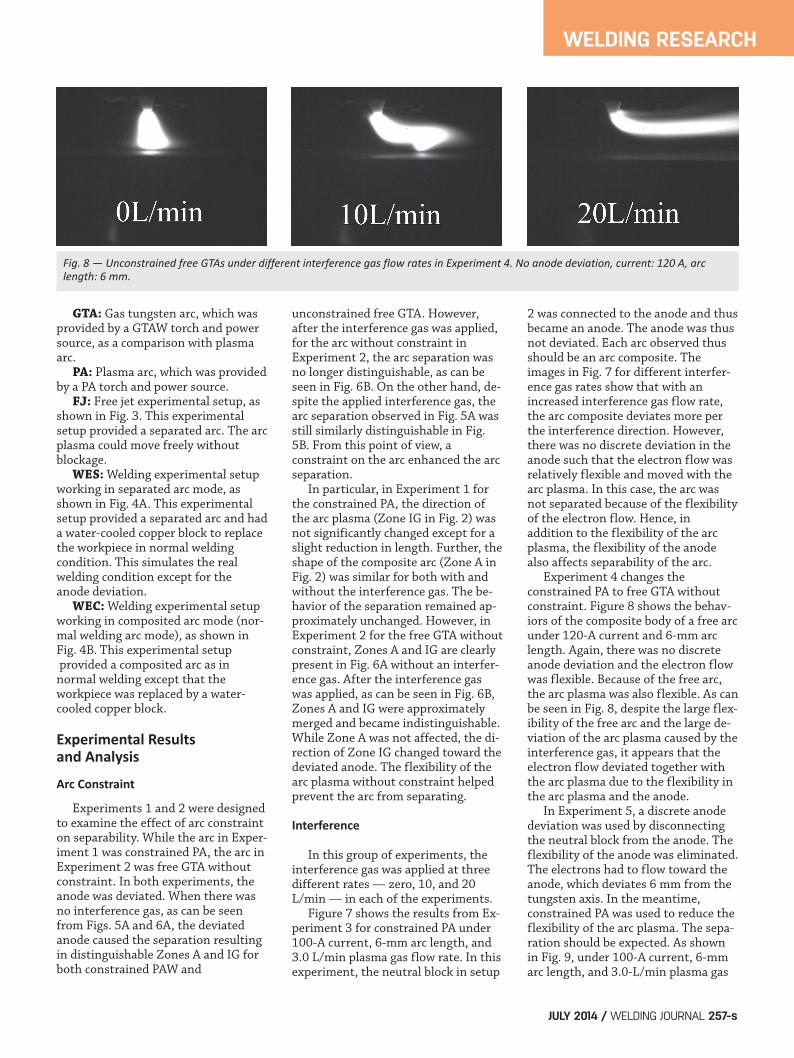
2 was connected to the anode and thusbecame an anode. The anode was thusnot deviated. Each arc observed thusshould be an arc composite. Theimages in Fig. 7 for different interfer-ence gas rates show that with anincreased interference gas flow rate,the arc composite deviates more perthe interference direction. However,there was no discrete deviation in theanode such that the electron flow wasrelatively flexible and moved with thearc plasma. In this case, the arc wasnot separated because of the flexibilityof the electron flow. Hence, inaddition to the flexibility of the arcplasma, the flexibility of the anodealso affects separability of the arc. Experiment 4 changes theconstrained PA to free GTA withoutconstraint. Figure 8 shows the behav-iors of the composite body of a free arcunder 120-A current and 6-mm arclength. Again, there was no discreteanode deviation and the electron flowwas flexible. Because of the free arc,the arc plasma was also flexible. As canbe seen in Fig. 8, despite the large flex-ibility of the free arc and the large de-viation of the arc plasma caused by theinterference gas, it appears that theelectron flow deviated together withthe arc plasma due to the flexibility inthe arc plasma and the anode. In Experiment 5, a discrete anodedeviation was used by disconnectingthe neutral block from the anode. Theflexibility of the anode was eliminated.The electrons had to flow toward theanode, which deviates 6 mm from thetungsten axis. In the meantime,constrained PA was used to reduce theflexibility of the arc plasma. The sepa-ration should be expected. As shownin Fig. 9, under 100-A current, 6-mmarc length, and 3.0-L/min plasma gas
WELDING RESEARCH
JULY 2014 / WELDING JOURNAL 257-s
Fig. 8 — Unconstrained free GTAs under different interference gas flow rates in Experiment 4. No anode deviation, current: 120 A, arclength: 6 mm.
Final Chen Layout_Layout 1 6/13/14 10:25 AM Page 257
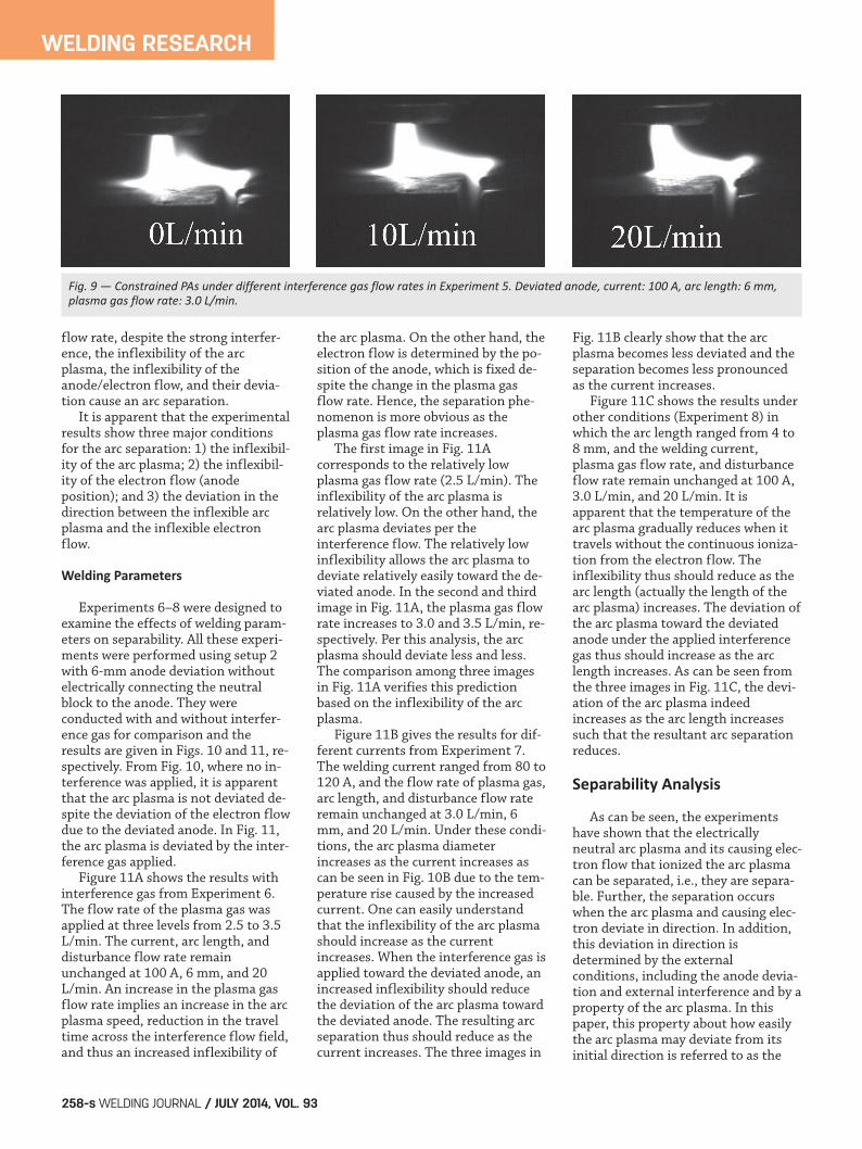
flow rate, despite the strong interfer-ence, the inflexibility of the arcplasma, the inflexibility of theanode/electron flow, and their devia-tion cause an arc separation. It is apparent that the experimentalresults show three major conditionsfor the arc separation: 1) the inflexibil-ity of the arc plasma; 2) the inflexibil-ity of the electron flow (anodeposition); and 3) the deviation in thedirection between the inflexible arcplasma and the inflexible electronflow.
Welding Parameters
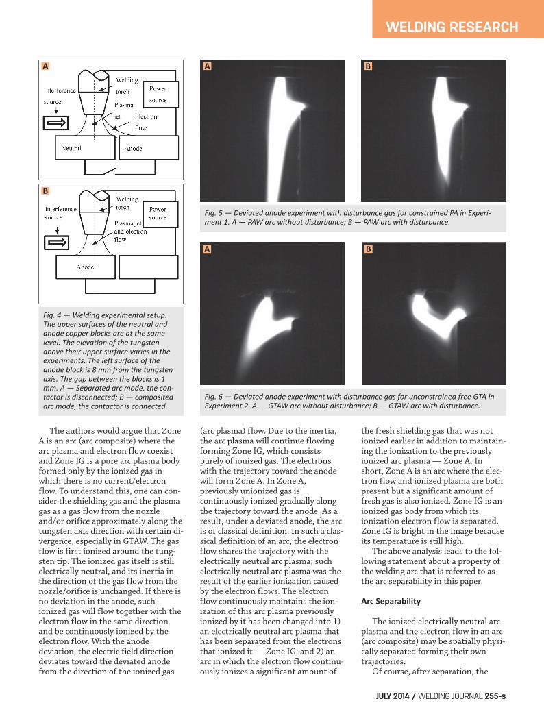
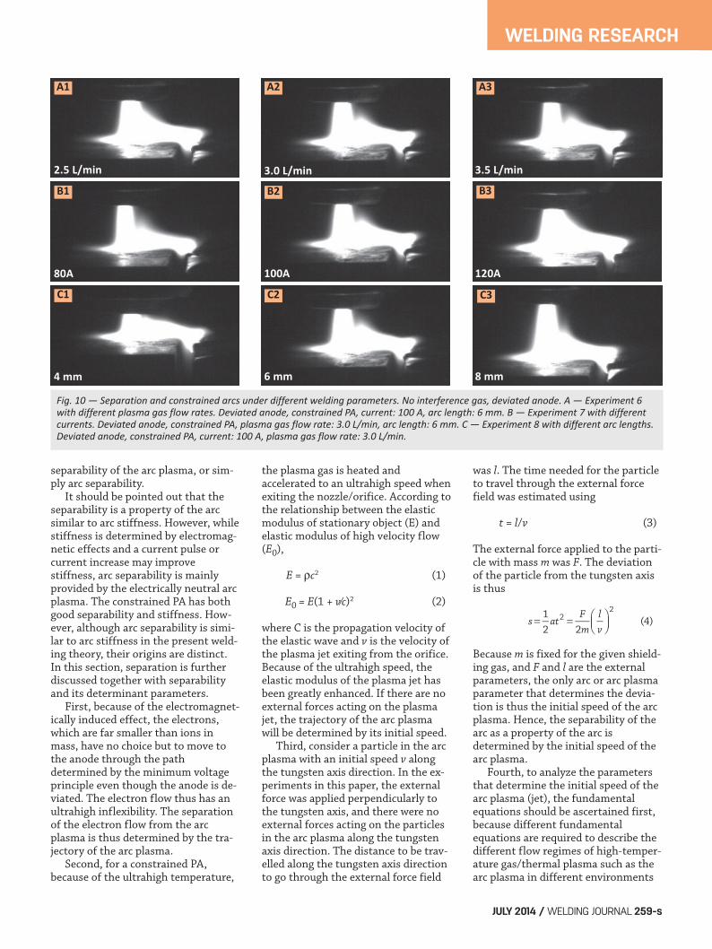
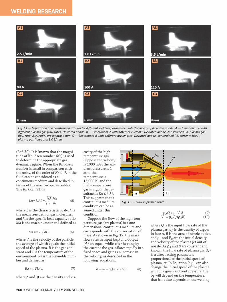
Experiments 6–8 were designed toexamine the effects of welding param-eters on separability. All these experi-ments were performed using setup 2with 6-mm anode deviation withoutelectrically connecting the neutralblock to the anode. They wereconducted with and without interfer-ence gas for comparison and theresults are given in Figs. 10 and 11, re-spectively. From Fig. 10, where no in-terference was applied, it is apparentthat the arc plasma is not deviated de-spite the deviation of the electron flowdue to the deviated anode. In Fig. 11,the arc plasma is deviated by the inter-ference gas applied. Figure 11A shows the results withinterference gas from Experiment 6.The flow rate of the plasma gas wasapplied at three levels from 2.5 to 3.5L/min. The current, arc length, anddisturbance flow rate remainunchanged at 100 A, 6 mm, and 20L/min. An increase in the plasma gasflow rate implies an increase in the arcplasma speed, reduction in the traveltime across the interference flow field,and thus an increased inflexibility of
the arc plasma. On the other hand, theelectron flow is determined by the po-sition of the anode, which is fixed de-spite the change in the plasma gasflow rate. Hence, the separation phe-nomenon is more obvious as theplasma gas flow rate increases. The first image in Fig. 11Acorresponds to the relatively lowplasma gas flow rate (2.5 L/min). Theinflexibility of the arc plasma isrelatively low. On the other hand, thearc plasma deviates per theinterference flow. The relatively lowinflexibility allows the arc plasma todeviate relatively easily toward the de-viated anode. In the second and thirdimage in Fig. 11A, the plasma gas flowrate increases to 3.0 and 3.5 L/min, re-spectively. Per this analysis, the arcplasma should deviate less and less.The comparison among three imagesin Fig. 11A verifies this predictionbased on the inflexibility of the arcplasma. Figure 11B gives the results for dif-ferent currents from Experiment 7.The welding current ranged from 80 to120 A, and the flow rate of plasma gas,arc length, and disturbance flow rateremain unchanged at 3.0 L/min, 6mm, and 20 L/min. Under these condi-tions, the arc plasma diameterincreases as the current increases ascan be seen in Fig. 10B due to the tem-perature rise caused by the increasedcurrent. One can easily understandthat the inflexibility of the arc plasmashould increase as the currentincreases. When the interference gas isapplied toward the deviated anode, anincreased inflexibility should reducethe deviation of the arc plasma towardthe deviated anode. The resulting arcseparation thus should reduce as thecurrent increases. The three images in
Fig. 11B clearly show that the arcplasma becomes less deviated and theseparation becomes less pronouncedas the current increases. Figure 11C shows the results underother conditions (Experiment 8) inwhich the arc length ranged from 4 to8 mm, and the welding current,plasma gas flow rate, and disturbanceflow rate remain unchanged at 100 A,3.0 L/min, and 20 L/min. It isapparent that the temperature of thearc plasma gradually reduces when ittravels without the continuous ioniza-tion from the electron flow. Theinflexibility thus should reduce as thearc length (actually the length of thearc plasma) increases. The deviation ofthe arc plasma toward the deviatedanode under the applied interferencegas thus should increase as the arclength increases. As can be seen fromthe three images in Fig. 11C, the devi-ation of the arc plasma indeedincreases as the arc length increasessuch that the resultant arc separationreduces.
Separability Analysis
As can be seen, the experimentshave shown that the electricallyneutral arc plasma and its causing elec-tron flow that ionized the arc plasmacan be separated, i.e., they are separa-ble. Further, the separation occurswhen the arc plasma and causing elec-tron deviate in direction. In addition,this deviation in direction isdetermined by the externalconditions, including the anode devia-tion and external interference and by aproperty of the arc plasma. In thispaper, this property about how easilythe arc plasma may deviate from itsinitial direction is referred to as the
WELDING RESEARCH
WELDING JOURNAL / JULY 2014, VOL. 93258-s
Fig. 9 — Constrained PAs under different interference gas flow rates in Experiment 5. Deviated anode, current: 100 A, arc length: 6 mm,plasma gas flow rate: 3.0 L/min.
Final Chen Layout_Layout 1 6/13/14 10:25 AM Page 258
separability of the arc plasma, or sim-ply arc separability. It should be pointed out that theseparability is a property of the arcsimilar to arc stiffness. However, whilestiffness is determined by electromag-netic effects and a current pulse orcurrent increase may improvestiffness, arc separability is mainlyprovided by the electrically neutral arcplasma. The constrained PA has bothgood separability and stiffness. How-ever, although arc separability is simi-lar to arc stiffness in the present weld-ing theory, their origins are distinct.In this section, separation is furtherdiscussed together with separabilityand its determinant parameters. First, because of the electromagnet-ically induced effect, the electrons,which are far smaller than ions inmass, have no choice but to move tothe anode through the pathdetermined by the minimum voltageprinciple even though the anode is de-viated. The electron flow thus has anultrahigh inflexibility. The separationof the electron flow from the arcplasma is thus determined by the tra-jectory of the arc plasma. Second, for a constrained PA,because of the ultrahigh temperature,
the plasma gas is heated andaccelerated to an ultrahigh speed whenexiting the nozzle/orifice. According tothe relationship between the elasticmodulus of stationary object (E) andelastic modulus of high velocity flow(E0),
E = ρc2 (1)
E0 = E(1 + v⁄c)2 (2)
where C is the propagation velocity ofthe elastic wave and v is the velocity ofthe plasma jet exiting from the orifice.Because of the ultrahigh speed, theelastic modulus of the plasma jet hasbeen greatly enhanced. If there are noexternal forces acting on the plasmajet, the trajectory of the arc plasmawill be determined by its initial speed. Third, consider a particle in the arcplasma with an initial speed v alongthe tungsten axis direction. In the ex-periments in this paper, the externalforce was applied perpendicularly tothe tungsten axis, and there were noexternal forces acting on the particlesin the arc plasma along the tungstenaxis direction. The distance to be trav-elled along the tungsten axis directionto go through the external force field
was l. The time needed for the particleto travel through the external forcefield was estimated using
t = l/v (3)
The external force applied to the parti-cle with mass m was F. The deviationof the particle from the tungsten axisis thus
Because m is fixed for the given shield-ing gas, and F and l are the externalparameters, the only arc or arc plasmaparameter that determines the devia-tion is thus the initial speed of the arcplasma. Hence, the separability of thearc as a property of the arc isdetermined by the initial speed of thearc plasma. Fourth, to analyze the parametersthat determine the initial speed of thearc plasma (jet), the fundamentalequations should be ascertained first,because different fundamentalequations are required to describe thedifferent flow regimes of high-temper-ature gas/thermal plasma such as thearc plasma in different environments
12 2
(4)22
= = ⎛⎝⎜
⎞⎠⎟s at
Fm
lv
WELDING RESEARCH
JULY 2014 / WELDING JOURNAL 259-s
Fig. 10 — Separation and constrained arcs under different welding parameters. No interference gas, deviated anode. A — Experiment 6with different plasma gas flow rates. Deviated anode, constrained PA, current: 100 A, arc length: 6 mm. B — Experiment 7 with differentcurrents. Deviated anode, constrained PA, plasma gas flow rate: 3.0 L/min, arc length: 6 mm. C — Experiment 8 with different arc lengths.Deviated anode, constrained PA, current: 100 A, plasma gas flow rate: 3.0 L/min.
A1
B1
A2
B2
A3
B3
C1 C2 C3
2.5 L/min 3.0 L/min 3.5 L/min
80A 100A 120A
4 mm 8 mm6 mm
Final Chen Layout_Layout 1 6/13/14 10:25 AM Page 259
(Ref. 30). It is known that the magni-tude of Knudsen number (Kn) is usedto determine the appropriate gasdynamic regime. When the Knudsennumber is small in comparison withthe unity, of the order of Kn ≤ 10–1, thefluid can be considered as acontinuous medium and described interms of the macroscopic variables.The Kn (Ref. 31) is
where L is the characteristic scale, λ isthe mean free path of gas molecules,and k is the specific heat capacity ratio.Ma is the mach number and defined as
where V is the velocity of the particle,the average of which equals the initialspeed of the plasma. R is the gas con-stant and T is the temperature of theenvironment. Re is the Reynolds num-ber and defined as
Re = ρVL ⁄ μ (7)
where ρ and μ are the density and vis-
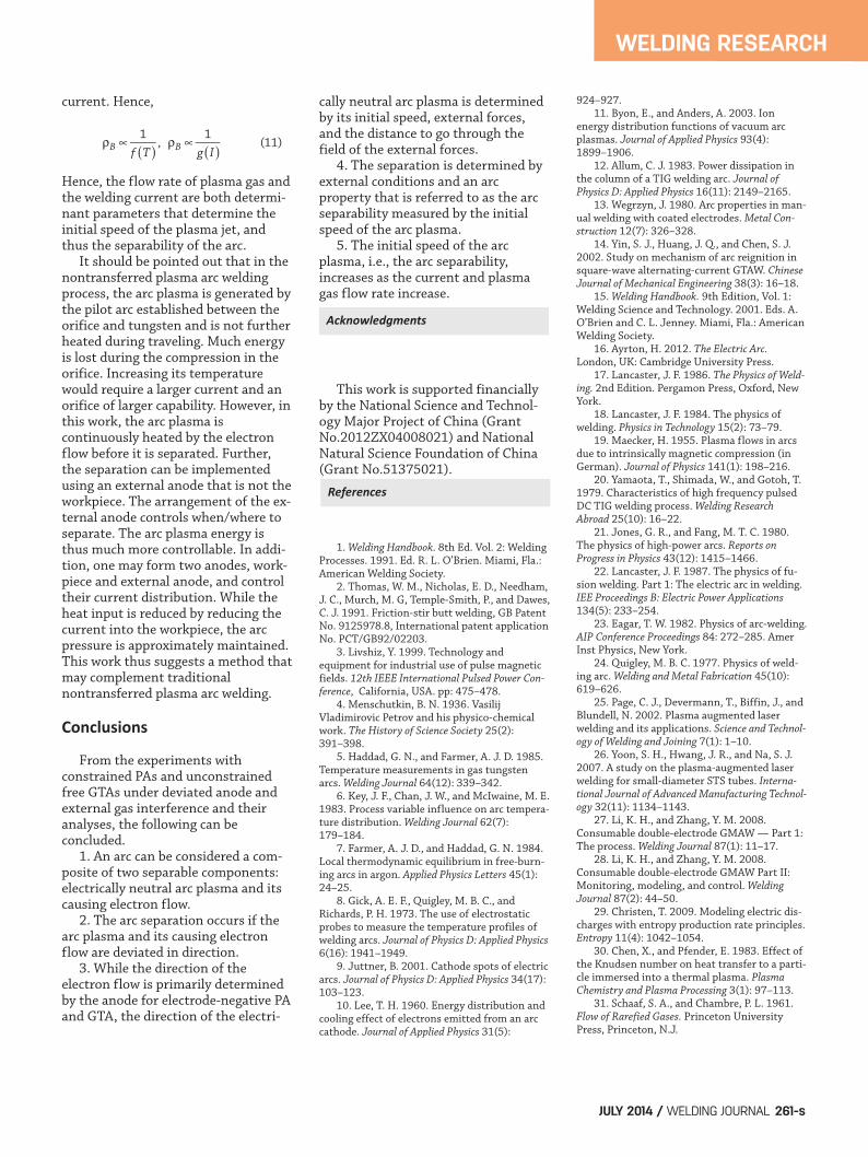
cosity of the high-temperature gas.Suppose the velocityis 1000 m/s, the am-bient pressure is 1atm, thetemperature is15,000 K, and thehigh-temperaturegas is argon, the re-sultant is Kn ≤ 10–1.This suggests that acontinuous mediumcondition can be as-sumed under thiscondition. Suppose the flow of the high-tem-perature gas (arc plasma) is a one-dimensional continuous medium andcorresponds with the conservation ofmass. As shown in Fig. 12, the massflow rates in input (m0) and output(m) are equal, while after heating bythe current the gas inflates rapidly in afixed space and gains an increase inthe velocity, as described in the following equations:
ρAQ = ρBVBB (9)VB = ρAQ/(ρBB) (10)
where Q is the input flow rate of theplasma gas, ρA is the density of argonin face A, B is the area of nozzle outlet,and ρB and VB are the initial densityand velocity of the plasma jet out ofnozzle. As ρA and B are constant andknown, the flow rate of plasma gas (Q)is a direct acting parameter,proportional to the initial speed ofplasma jet. In Equation 9, ρB can alsochange the initial speed of the plasmajet. For a given ambient pressure, theρB will depend on the temperature,that is, it also depends on the welding
= λ =π
Kn / Lk Ma
Re2(5)
=Ma V / kRT (6)
(8)0 = = ρ =m m Q constant
WELDING RESEARCH
WELDING JOURNAL / JULY 2014, VOL. 93260-s
Fig. 11 — Separation and constrained arcs under different welding parameters. Interference gas, deviated anode. A — Experiment 6 withdifferent plasma gas flow rates. Deviated anode. B — Experiment 7 with different currents. Deviated anode, constrained PA, plasma gasflow rate: 3.0 L/min, arc length: 6 mm. C — Experiment 8 with different arc lengths. Deviated anode, constrained PA, current: 100 A,plasma gas flow rate: 3.0 L/min.
Fig. 12 — Flow in plasma torch.
A1
B1
A2
B2
A3
B3
C1 C2 C3
2.5 L/min
80 A
4 mm
3.0 L/min
100 A
6 mm
3.5 L/min
120 A
8mm
..
Final Chen Layout_Layout 1 6/13/14 2:31 PM Page 260
current. Hence,
Hence, the flow rate of plasma gas andthe welding current are both determi-nant parameters that determine theinitial speed of the plasma jet, andthus the separability of the arc. It should be pointed out that in thenontransferred plasma arc weldingprocess, the arc plasma is generated bythe pilot arc established between theorifice and tungsten and is not furtherheated during traveling. Much energyis lost during the compression in theorifice. Increasing its temperaturewould require a larger current and anorifice of larger capability. However, inthis work, the arc plasma iscontinuously heated by the electronflow before it is separated. Further,the separation can be implementedusing an external anode that is not theworkpiece. The arrangement of the ex-ternal anode controls when/where toseparate. The arc plasma energy isthus much more controllable. In addi-tion, one may form two anodes, work-piece and external anode, and controltheir current distribution. While theheat input is reduced by reducing thecurrent into the workpiece, the arcpressure is approximately maintained.This work thus suggests a method thatmay complement traditionalnontransferred plasma arc welding.
Conclusions
From the experiments withconstrained PAs and unconstrainedfree GTAs under deviated anode andexternal gas interference and theiranalyses, the following can beconcluded. 1. An arc can be considered a com-posite of two separable components:electrically neutral arc plasma and itscausing electron flow. 2. The arc separation occurs if thearc plasma and its causing electronflow are deviated in direction. 3. While the direction of theelectron flow is primarily determinedby the anode for electrode-negative PAand GTA, the direction of the electri-
cally neutral arc plasma is determinedby its initial speed, external forces,and the distance to go through thefield of the external forces. 4. The separation is determined byexternal conditions and an arcproperty that is referred to as the arcseparability measured by the initialspeed of the arc plasma. 5. The initial speed of the arcplasma, i.e., the arc separability,increases as the current and plasmagas flow rate increase.
This work is supported financiallyby the National Science and Technol-ogy Major Project of China (GrantNo.2012ZX04008021) and NationalNatural Science Foundation of China(Grant No.51375021).
1. Welding Handbook. 8th Ed. Vol. 2: WeldingProcesses. 1991. Ed. R. L. O’Brien. Miami, Fla.:American Welding Society. 2. Thomas, W. M., Nicholas, E. D., Needham,J. C., Murch, M. G, Temple-Smith, P., and Dawes,C. J. 1991. Friction-stir butt welding, GB PatentNo. 9125978.8, International patent applicationNo. PCT/GB92/02203. 3. Livshiz, Y. 1999. Technology andequipment for industrial use of pulse magneticfields. 12th IEEE International Pulsed Power Con-ference, California, USA. pp: 475–478. 4. Menschutkin, B. N. 1936. VasilijVladimirovic Petrov and his physico-chemicalwork. The History of Science Society 25(2):391–398. 5. Haddad, G. N., and Farmer, A. J. D. 1985.Temperature measurements in gas tungstenarcs. Welding Journal 64(12): 339–342. 6. Key, J. F., Chan, J. W., and McIwaine, M. E.1983. Process variable influence on arc tempera-ture distribution. Welding Journal 62(7):179–184. 7. Farmer, A. J. D., and Haddad, G. N. 1984.Local thermodynamic equilibrium in free‐burn-ing arcs in argon. Applied Physics Letters 45(1):24–25. 8. Gick, A. E. F., Quigley, M. B. C., andRichards, P. H. 1973. The use of electrostaticprobes to measure the temperature profiles ofwelding arcs. Journal of Physics D: Applied Physics6(16): 1941–1949. 9. Juttner, B. 2001. Cathode spots of electricarcs. Journal of Physics D: Applied Physics 34(17):103–123. 10. Lee, T. H. 1960. Energy distribution andcooling effect of electrons emitted from an arccathode. Journal of Applied Physics 31(5):
924–927. 11. Byon, E., and Anders, A. 2003. Ionenergy distribution functions of vacuum arcplasmas. Journal of Applied Physics 93(4):1899–1906. 12. Allum, C. J. 1983. Power dissipation inthe column of a TIG welding arc. Journal ofPhysics D: Applied Physics 16(11): 2149–2165. 13. Wegrzyn, J. 1980. Arc properties in man-ual welding with coated electrodes. Metal Con-struction 12(7): 326–328. 14. Yin, S. J., Huang, J. Q., and Chen, S. J.2002. Study on mechanism of arc reignition insquare-wave alternating-current GTAW. ChineseJournal of Mechanical Engineering 38(3): 16–18. 15. Welding Handbook. 9th Edition, Vol. 1:Welding Science and Technology. 2001. Eds. A.O’Brien and C. L. Jenney. Miami, Fla.: AmericanWelding Society. 16. Ayrton, H. 2012. The Electric Arc.London, UK: Cambridge University Press. 17. Lancaster, J. F. 1986. The Physics of Weld-ing. 2nd Edition. Pergamon Press, Oxford, NewYork. 18. Lancaster, J. F. 1984. The physics ofwelding. Physics in Technology 15(2): 73–79. 19. Maecker, H. 1955. Plasma flows in arcsdue to intrinsically magnetic compression (inGerman). Journal of Physics 141(1): 198–216. 20. Yamaota, T., Shimada, W., and Gotoh, T.1979. Characteristics of high frequency pulsedDC TIG welding process. Welding ResearchAbroad 25(10): 16–22. 21. Jones, G. R., and Fang, M. T. C. 1980.The physics of high-power arcs. Reports onProgress in Physics 43(12): 1415–1466. 22. Lancaster, J. F. 1987. The physics of fu-sion welding. Part 1: The electric arc in welding.IEE Proceedings B: Electric Power Applications134(5): 233–254. 23. Eagar, T. W. 1982. Physics of arc-welding.AIP Conference Proceedings 84: 272–285. AmerInst Physics, New York. 24. Quigley, M. B. C. 1977. Physics of weld-ing arc. Welding and Metal Fabrication 45(10):619–626. 25. Page, C. J., Devermann, T., Biffin, J., andBlundell, N. 2002. Plasma augmented laserwelding and its applications. Science and Technol-ogy of Welding and Joining 7(1): 1–10. 26. Yoon, S. H., Hwang, J. R., and Na, S. J.2007. A study on the plasma-augmented laserwelding for small-diameter STS tubes. Interna-tional Journal of Advanced Manufacturing Technol-ogy 32(11): 1134–1143. 27. Li, K. H., and Zhang, Y. M. 2008.Consumable double-electrode GMAW — Part 1:The process. Welding Journal 87(1): 11–17. 28. Li, K. H., and Zhang, Y. M. 2008.Consumable double-electrode GMAW Part II:Monitoring, modeling, and control. WeldingJournal 87(2): 44–50. 29. Christen, T. 2009. Modeling electric dis-charges with entropy production rate principles.Entropy 11(4): 1042–1054. 30. Chen, X., and Pfender, E. 1983. Effect ofthe Knudsen number on heat transfer to a parti-cle immersed into a thermal plasma. PlasmaChemistry and Plasma Processing 3(1): 97–113. 31. Schaaf, S. A., and Chambre, P. L. 1961.Flow of Rarefied Gases. Princeton UniversityPress, Princeton, N.J.
1 1(11)( ) ( )ρ ∝ ρ ∝
f T,
g IB B
WELDING RESEARCH
JULY 2014 / WELDING JOURNAL 261-s
Acknowledgments
References
Final Chen Layout_Layout 1 6/13/14 10:25 AM Page 261