Sentinel SCD QRM
60
Sentinel Products Quick Reference Manual 450-0378-001 Rev. I
-
Upload
antonysolenc -
Category
Documents
-
view
242 -
download
2
Transcript of Sentinel SCD QRM

Sentinel ProductsQuick Reference Manual
450-0378-001 Rev. I

Copyright © 2007 by TIDEL ENGINEERING, L.P.
All rights reserved. No part of this manual may be reproduced, stored in a retrieval system, or transmitted in any form or by any means, electronic, mechanical, photocopying, recording, or other-wise, except as may be expressly permitted by the applicable copy-right statutes or in writing by Tidel Engineering, L.P.
For information, write: Tidel Engineering, 2025 W. Belt Line Rd, #114
Carrollton, TX 75006, (972)484-3358
Tidel would like to thank you for purchasing this Sentinel product.
To maintain proper working order, we recommend you read this manual completely and perform the preventive maintenance rou-tines at the suggested intervals.
The Manufacturer’s Warranty is limited to defects in workmanship and equipment hardware. Repairs due to lack of Preventive Mainte-nance (and Preventive Maintenance itself), are not covered by the Manufacturer’s Warranty.
ITEMS THAT REQUIRE PREVENTIVE MAINTENANCEITEMS THAT REQUIRE PREVENTIVE MAINTENANCEBill Acceptors - Pages 21 - 33
Clean with Cleaning Cards on a routine basis (dependent on location’s volume of traffi c) or manually at suggest intervals.
Screen Protectors - Page 55Should be replaced when the Touchscreen response be-comes erratic.
Coin Hopper Exit Sensors - Page 36Cleaning should be performed on a routine basis (depen-dent on location’s volume of traffi c).
Combination Lock Battery Replacement - Page 54Repeated beeping during opening or a continuous fl ashing LED indicates a low battery condition.
Additional items not covered by warranty, but not limited to:Additional items not covered by warranty, but not limited to:AbuseDamage to cassettes due to mis-handling.Coin/Bill Jams Screen protector damage or replacementNetwork or phone line related problems.Damage due to spillageEquipment resetsPhone fi xable problemsUser Programming problemsEquipment or software upgradesPrinter jams

ContentsLicense Agreement 1
Mandatory Programming 2
Component Location 5
Printers 9
Touchscreen Layout/Entry 11
Operations Performed From the Main Screen 12
Vault Door Operations 17
Placing Items In The Courier Tray 17
Courier Key Operations 18
Tube Vending Operations 19
Bill Acceptor Operations 21
Clearing Bill Acceptor Totals 21
Coin Dispenser Operations 34
Bill Dispenser Operations 38
End Of Day/Shift Operations 44
Adjusting Vault Contents 45
Moving Vault Contents 46
Printing Reports 48
Adding A Clerk 49
Troubleshooting 50
Combination Lock Maintenance 54
Screen Protector Replacement 55
Paper Specifi cations and Part Numbers 56
Manager Menu Maps 57
Warranty Policy 59

License Agreement
You have acquired a device (SCD) that includes software licensed by Tidel Engineering from Microsoft Licensing Inc. or its affi liates (“MS”). Those in-stalled software products of MS origin, as well as associated media, printed materials, and “online” or electronic documentation (“Windows CE”), are
protected by international intellectual property laws and treaties. The soft-ware is licensed, not sold. All rights reserved.
IF YOU DO NOT AGREE TO THE END USER LICENSE AGREEMENT (“EULA”). DO NOT USE THIS DEVICE OR COPY THE SOFTWARE. INSTEAD, PROMPTLY CONTACT TIDEL ENGINEERING FOR IN-STRUCTIONS ON RETURN OF THE UNUSED DEVICE FOR A REFUND. ANY USE OF THE SOFTWARE, INCLUDING BUT NOT LIMITED TO THE USE ON THE DEVICE, WILL CONSTITUTE YOUR AGREEMENT TO THIS EULA (OR RATIFICATION OF ANY PREVIOUS CONSENT).
GRANT OF THE SOFTWARE LICENSE. This EULA grants you the following license:
You may use the SOFTWARE only on the DEVICE.
NOT FAULT TOLERANT. TIDEL ENGINEERING HAS INDEPENDENTLY DETERMINED HOW TO USE THE SOFTWARE IN THE DEVICE, AND MS HAS RELIED UPON TIDEL ENGINEERING TO CONDUCT SUFFICIENT TESTING TO DETERMINE THAT THE SOFTWARE IS SUITABLE FOR SUCH USE.
NO WARRANTIES FOR THE SOFTWARE. THE SOFTWARE is provided “AS IS” and with all faults. THE ENTIRE RISK AS TO SATISFACTORY QUALITY, PERFORMANCE, ACCURACY, AND EFFORT (INCLUDING LACK OF NEGELIGENCE) IS WITH YOU. ALSO, THERE IS NO WARRANTY AGAINST INTERFERENCE WITH YOUR ENJOYMENT OF THE SOFTWARE OR AGAINST INFRIGEMENT. IF YOU HAVE ANY WARRANTIES REGARDING THE DEVICE OR THE SOFTWARE, THOSE WARRANTIES DO NOT ORIGINATE FROM, AND ARE NOT BINDING ON, MS.
Note on Java Support. The SOFTWARE may contain support for programs written in Java. Java technology is not fault tolerant and is not designed, manufactured, or intended for use or resale as online control equipment in hazardous environments requiring fail-safe performance, such as in the operation of nuclear facilities, aircraft navigation or communications systems, air traffi c control, direct life support machines, or weapons systems, in which the failure of Java technology could lead directly to death, personal injury, or severe physical or environmental damage. Sun Microsystems, Inc. has contractually obligated MS to make this disclaimer.
No Liability for Certain Damages. EXCEPT AS PROHIBITED BY LAW, MS SHALL HAVE NO LIABIL-ITY FOR ANY INDIRECT, SPECIAL, CONSEQUENTIAL OR INCIDENTAL DAMAGES ARISING FROM OR IN CONNECTION WITH THE USE OR PERFORMANCE OF THE SOFTWARE. THIS LIMITATION SHALL APPLY EVEN IF ANY REMEDY FAILS OF ITS ESSENTIAL PURPOSE. IN NO EVENT SHALL MS BE LIABLE FOR ANY AMOUNT IN EXCESS OF U.S. TWO HUNDRED FIFTY DOLLARS (U.S. $250.00).
Limitations on Reverse Engineering, Decompilation, and Disassembly. You may not reverse engi-neer, decompile, or disassemble the SOFTWARE, except and only to the extent that such activity is expressly permitted by application law notwithstanding this limitation.
SOFTWARE TRANSFER ALLOWED BUT WITH RESTRICTIONS. You may permanently transfer rights under this EULA only as part of a permanent sale or transfer of the Device, and only if the recipi-ent agrees to this EULA. If the SOFTWARE is an upgrade, any transfer must also include all prior versions of the SOFTWARE.
EXPORT RESTRICTIONS. You acknowledge that SOFTWARE is of US-origin. You agree to comply with all applicable international and national laws that apply to the SOFTWARE, including the U.S. Export Administration Regulations, as well as end-user, end-use and country destination restrictions issued by U.S. and other governments. For additional information on exporting the SOFTWARE, see http://www.microsoft.com/exporting/.
1

When power is applied to the unit, the Main Screen will be displayed at start-up:
Step 1: Executive Code entry:
Select Log In and enter the default Executive code (123456)
If the unit has been pre-programmed at the factory for customer settings, the customer must provide the Executive code.
Step 2: Store Name/Number - Tap the Touchscreen icon until the desired character appears (4 to 16 characters) and press “DONE”.
NOTE: To bypass the Store Number entry, select “GO BACK”..
All Units:
Step 1: Setup Clerk and Manager Codes
Log In > More > Accounts > (select account type) > Add
Enter the desired PIN Code (4 to 9 numbers) and select “ENTER”.
Verify the PIN Code - Re-Enter the PIN Code and select “ENTER”.
Enter the Name - Tap the Touchscreen icon until the desired characters appears and press “DONE”. (2 to 8 characters).
Set the User’s privileges from the available menus and select “SAVE” to exit.
Select “ADD” to enter another account.Select “GO BACK” to select a different account type.
Step 2: Date and Time
Log In > More > Date/Time
Enter the Date and time in a MM-DD-YY-HH-MM for-mat.
Select AM or PM (if applicable), then select enter.
Select “GO BACK” until the Main Screen appears.
☞
☞
a)
b)
c)
d)
a)
b)
c)
Mandatory Programming
2

Tube Vending Operations:Tube Vending Operations:
Step 1: Confi gure column amount (the amount in a single tube, in each column).
Log In > Cash Control > Confi gure Columns
Select the desired column.
Select the Denomination type.
Select the number of bills per tube and select “EN-TER” (Bills only).
Select another column or proceed to the next step.
Select “DONE” to exit and save your settings.
Bulk Coin Dispenser Operations:Bulk Coin Dispenser Operations:
Step 1: Confi gure Hopper amounts (the denomination type to be loaded in each Hopper):
Log In > Cash Control > Confi gure Dispense Choices > Coin Hopper Control > Setup Hoppers
Select the desired Hopper.Enable the Hopper.Select the denomination type (by country).Assign the coin value. Select “DONE” to exit and save your settings.Repeat steps “a - e” for all hoppers being used.Select “DONE” to exit and save your settings.
Step 2: Confi gure the coin dispense selections:
Log In > Cash Control > Confi gure Dispense Choices > Coin Hopper Control > Set Choices
Select an available dispense selection icon.Select the number of hoppers the coins will be dis-pensed from. Select coin denomination type and the number of coins to dispense. Repeat step “C” for each coin denomination type.Enter a description for the selection.Repeat steps “a - e” for all desired Select “DONE” to exit and save your settings.
a)
b)
c)
d)
e)
a)b)c)d)e)f)g)
a)b)
c)
d)e)f)g)
Mandatory Programming
3

Bill Dispenser Operations:Bill Dispenser Operations:
Step 1: Confi gure the Cassette denominations:
Log In > Cash Control > Confi gure Dispense Choices > Confi gure Dispenser > Cassette Confi guration
Select the desired CassetteSelect the denomination type (by country).Select the bill value by selecting the amount icon until the correct value appears.Select “DONE” to exit the cassette confi guration.Repeat steps “a - d” for all cassettes being used.Select “DONE” to exit and save your settings.
Step 2: Confi gure the coin dispense selections:
Log In > Cash Control > Confi gure Dispense Choices > Confi gure Dispenser > Confi gure Dispense Choices
Select an available dispense selection icon.Select the number of cassettes the bills will be dis-pensed from. Select bill denomination type and the number of bills to dispense. Repeat steps “a - c” for all the desired dispense selec-tions. Select “GO BACK” to exit and save your settings.
Report Types:Report Types:
Step 1: Report Type:
Log In > More > Policy > Reports
Select “Unknown Report Type” icon.From the list of available report types, select a report style that will best suit the report needs of the store.
NOTE: “Original” or “Kasper” report styles may fi t the needs of most non-specifi c customers, however, the customer may wish to experiment with different report styles to fi nd the type that best fi ts their operation.
a)b)c)
d)e)f)
a)b)
c)
d)
e)
a)b)
Mandatory Programming
4

Sentinel Controller Equipped With 2 Bill Acceptors
Removable Bezel (for Screen Protector replacement)Bill AcceptorsTouchscreen DataKey ReaderDrop Chute HandlePrinter Paper Loading Door Release ButtonBill Acceptor Vault Door HandleDrop Vault Door Handle3 Amp Slow-Blow FuseReset ButtonBill Acceptor Head Removal HandlePaper Feed ButtonOptional Combination Lock (not shown)
1)2)3)4)5)6)7)8)9)10)11)12)
5
1 2
1111
8
99
3
5
7
61010
4
1212

Sentinel Controller With 1 Bill Acceptor and Tube Vend
Drop ChuteBill AcceptorBezel (for screen protector replacement)Tube Dispenser Service Door LockTube Loading Gate/AccessPrinter Door Release LeverTube Retrieval TrayTouchscreenDataKey Reader3 Amp Slow-Blow Fuse/Reset ButtonPrinter Paper Feed ButtonAcceptor Vault Door HandleCourier Tray (located inside Main Vault)Main Vault Door Handle
1)2)3)4)5)6)7)8)9)10)11)12)13)14)
6
1
5
7
8
9
3 42
6
1010
11
1212
1313
1414

Sentinel Controller With Bulk Coin Dispenser
Coin Vault Door HandleRemovable Bezel (for Screen Protector replacement)Bill AcceptorsTouchscreen Drop Chute HandlePrinter Paper Loading Door Release ButtonBill Acceptor Vault Door HandleDrop Vault Door HandleDataKey ReaderReset Button and 3 Amp Slow-Blow FusePaper Feed ButtonCoin Receiving Cups (8)Combination Lock
1)2)3)4)5)6)7)8)9)10)11)12)13)
7
1 2
1212
1313
8
10
3
4
5
7
6
1111
9

Coin/Note Vault Door HandleRemovable Bezel (for Screen Protector replacement)Bill AcceptorsTouchscreen DataKey ReaderDrop Chute HandleBill Acceptor Vault Door HandleDrop Vault Door HandleDispenser Bill ExitReset Button and 3 Amp Slow-Blow FusePaper Feed ButtonCoin Receiving Trays (6)Combination LockPaper Loading Door Release Lever
1)2)3)4)5)6)7)8)9)10)11)12)13)14)
1 2
1212 1313
8
10
3
4
5
7
6
1111
9
14
Sentinel Controller With Bulk Coin Dispenser and Bill Dispenser
8

Integrated Printers
Step 1: Press down on the paper door release button to expose the paper tray.
Step 2: Pull enough paper off the roll to extend out of the paper tray and place the paper into the tray so the paper comes off the top off the roll.
Step 3: Close the paper tray door and tear off the excess paper extending out of tray.
Step 4: Press the paper feed button to insure paper feeds properly.
9

Epson Printers
Step 1: Open the Paper Loading Door.
Step 2: Load the paper roll so that the paper comes off the bottom of the roll.
Step 3: Pull the paper above the printer and close the the Paper Loading door on the paper.
Step 4: Tear off the excess paper and press the Feed Button to insure paper feeds properly.
10

NOTE: The top line of the Display indicates the current screen and entries made on the Touchscreen.
Use your fi ngertips to “tap” in selections. Do not use sharp, pointed objects to select entries.
To enter a character:Tap the corresponding icon repeatedly until the desired selection is displayed.
To advance to the next character:Pause entry selection for 1-2 seconds, then continue with the next character.
To backspace 1 character or clear an entry:To backspace 1 character or clear an entry:Select “Clear”.
To exit an Entry screen:To exit an Entry screen:Select “Done”.
To exit a Menu screen: Select “Go Back”.
To enter a space:To enter a space:Select the “789_” icon until an underscore “_” is dis-played.
☞
Touchscreen Layout/Entry
ABC DEF GHI
JKL
STU
123
Done
MNO
VWX
456
Clear
PQR
YZ0
789_
Go Back
Clerk1
11

Selecting an icon on the Main Screen will prompt the User for code entry.
Selections that appear on the Main Screen will vary de-pending on the confi guration and type of add-on modules equipped with the unit.
Buy Change
This feature will require the user to insert bills into the Bill Acceptor before funds can be dispensed.
(Time delay does not apply to the dispensing process when this feature is selected)
The Bill Acceptors will change to a “ready state”
The user may be prompted to “Buy Change” or “Buy Bills” using the selection in the bottom left corner of the screen.
As bills are inserted into the Acceptors, dispense selections equal to the “Deposit Credit” will appear on the display.
As funds are dispersed, dispense selections larger than the “Deposit Credit” will be removed from the display.
Press Done to exit the Buy Change menu
☞
☞
a)
b)
c)
d)
e)
Main Screen Operations
12
Log In
Main Screen version X.XXMain Screen version X.XXMain Screen version X.XX
Dispense Coins
Insert Bills
Load Tubes
Vault Drop
Vend Tube
Buy Change

Note: Any unused “Deposit Credit” cannot be carried over to the next vending transaction.
Cash Check
After code entry, enter the amount to be dispensed.
At the prompt, select the bill dispense order:
Assorted notes - the unit will dispense even amounts of each type of denomination.
Least number of notes - the unit will dispense bills from the highest denomination cassette, without go-ing over the requested amount.
The unit will then progress to the lower denominations until the correct amount is dispensed.
No Big Notes - the largest denomination (cassette). will not be dispensed during check cashing transac-tions.
After the notes have been dispensed, enter the amount of the check (drop).
You may be prompted to enter an envelope number.
Drop the check (envelope) into the drop chute.
Combo Dispenseombo DispenseA combo dispense transaction will dispense coins and bills in a single transaction
After code entry, the dispense selections will display avail-able coin and bill transactions.
Dispense Cash
After code entry, a menu of available bill dispensing selec-tions will appear.
Dispense Coins
After code entry, a menu of available coin dispensing selec-tions will appear.
1)
2)
3)
4)
5)
1)
1)
1)
Main Screen Operations
13

Insert Bills
After code entry, the Bill Acceptor will become active (ready state). Bills can be inserted into the Bill Acceptor.
The Bill Acceptor will become inactive (not ready state) 30 seconds after the last bill was inserted or when “Done” is selected.
Bills that have been marked inside the “Keep Out” area (with security marking pens, ink pens, pencils, etc...), are likely to
be rejected by the bill acceptors.
Load Tubes (by Clerk)
After the Clerk Code Entry:
The Sales Associate may be prompted to select the assigned register (If applicable).
The Sales Associate will be prompted to select the column and the number of tubes to be loaded.
1)
2)
1)
2)
Main Screen Operations
14
Keep Out Area

Load Tubes (by Manager)
After Manager code entry:
The Manager may be prompted to select the register con-taining funds used to fi ll the columns (If applicable).
If a register is selected, the Manager will be prompted to select the columns to be loaded.
If the Manager selects ”Not loading from register”, the prompt “Are you going to fi ll the columns?” will appear.
YES - The tube count in all columns will be set to 11.
NO - Column selection will appear, allowing the Manager to select columns and the number of tubes inserted into the corresponding column.
If funds exist in the Reserve/Vault, the prompt “Is the money for the tubes coming from the Main Vault?”
Selecting “YES” will deduct the total amount of the tubes loaded from the Reserve Fund/Vault.
Log In
The user will be prompted to enter a Clerk, Manager or Ex-ecutive code to access the appropriate menus.
Vault Drop
The user may be prompted to select the assigned register (If applicable).
The user may be prompted to select a Denomination type (If applicable).
The user will be prompted to enter the amount of the drop and verify the amount of the drop.
1)
2)
1)
1)
2)
3)
Main Screen Operations
15

Vend Tube
The user may be prompted to select the assigned register (If applicable).
The user will be prompted to select the column a tube will dispense from (If applicable).
After a tube is vended, the VEND TUBE icon will display “Report Problem”. Selecting this item will allow the User to report one of the following conditions:
Got the wrong stuff - The user will be prompted to enter the amount that was actually in the tube.
Nothing came out - No tube was dispensed.
The tube was empty - Nothing was in the tube.
The vend was OK - No problem will be reported.
The above reported problems will be noted on the Sum-mary, Shift and Transaction Reports.
1)
2)
3)
Main Screen Operations
16

17
Opening A VaultStep 1: Navigate to the “Open Vault” Menu.
Log In > (enter code) > Open Vault
Step 2: Select the desired vault to open (Drop Vault, Coin/Note Vault or Bill Acceptor Vault).
Step 3: After the door opening delay time has expired, the top line of the Display will indicate “Vault Wait Complete”.
Step 4: Navigate to the “Open Vault” Menu.
Log In > (enter code) > Open Vault
Step 5: Select the desired vault to open (Drop Vault, Coin/Note Vault or Bill Acceptor Vault).
Step 6: Turn the handle to open the Vault.
Opening A Vault Equipped WithA Combination Lock
NOTE: Four consecutive invalid entries will result in a fi ve minute lock-out (no combination entry is possible).
Step 1: Enter the six digit combination on the Combination Lock Keypad (the lock will beep TWO times if entry is correct)
Note: Three beeps indicate an invalid entry.
Step 2: Turn the Combination Lock face Clock-Wise to unlock the handle.
Step 3: Slide the Bill Acceptor Vault Door Handle to the left to open the door.
Placing Items In The Courier TrayStep 1: Open the Vault which conceals the Courier Tray.
Step 2: Place the items in the slot at the top of the Vault Door Frame.
Step 3: Close and lock the Vault.

Courier Key OperationsWhen a Courier DataKey is inserted and turned, the following Menu selections will appear:
Reports
Reports (see page 45), can be printed from this menu.
Notation
A 1-16 character notation can entered each time “YES” is selected (up to sixteen times).
Open Vaults
If the Courier has access to only one vault, the door can be opened after this menu item is selected.
If the Courier has access to multiple vaults, selections available to the Courier will be displayed.
Note: After a vault is opened by the Courier, the following additional items can be selected:
Reserve Change FundAllows entry of the amount left by the Courier.
Coin Hopper CountsAdd Coins - The number of coins entered will be added to the existing count.
New Coin Count - The existing coin count will be erased and the number of coins entered here will be-come the new coin count.
Dispenser CountsAdd Notes - The number of bills entered will be added to the existing count.
New Note Count - The existing bill count will be erased and the number of bills entered will be the new count.
Empty Reject TrayEmpty Reject Tray - Allows amounts shown in the reject tray to be cleared.
Change Pin
Allows The Courier to change the existing PIN number.
Clean Acceptors
Allows The Courier to access the Bill Acceptor Cleaning Menu (see page 20).
☞
☞
☞
☞
☞
18

Loading The Operating CashEach one of the 8 columns will hold 11 tubes each.
Step 1: All coins should be wrapped. Do not place tape over the end of the tube. Glue from the tape will eventually cause jams in the magazine.
NOTE: If loose coins are to be loaded into the tubes, end caps for the tubes can be purchased.
Step 2: Bills loaded into the tubes should be folded lengthwise and inserted into the tubes.
NOTE: Approximately 30 bills can be placed in a tube, however, bills that are “packed” into a tube will be diffi cult to remove and will not lay fl at in the cash register.
Step 3: Select LOAD TUBES from the Main Screen and enter a valid PIN when the prompt appears.
Step 4: The Tube Loading Gate will retract, allowing tubes to be loaded.
Step 5: Load the tubes, closed end 1st, to prevent coins from fall-ing out of the tube and into the magazine, causing jams.
The key above the tube loading holes provides access to the tube vending mechanism for service
19

Adjusting The Tube Count
NOTE: This function is typically used when the number of tubes shown on the report don’t match the dipstick reading.
Step 1: Navigate to the “Adjust Tube Counts” Menu.
Log In > (enter code) > Cash Control > Adjust Tube Counts
Step 2: The prompt to Add or Subtract will appear:
Add - Will increase the current tube count by the num-ber entered.
Subtract - Will decrease the current tube count by the number entered.
Step 3: Select the column you wish to adjust.
Step 4: Enter the number of the adjustment and select “Enter”.
Step 5: Select “Go Back” to exit the “Adjust Tube Counts” menu.
Checking The Number Of TubesStep 1: Insert the dipstick into the tube loading hole with the high-
est number fi rst.
Step 2: The number at the bottom of tube loading hole is the num-ber of tubes in the magazine.
NOTE: Leaving the dipstick in the magazine may result in a jammed vend mechanism.
20

Bill Acceptor General InformationBill Acceptor Cleaning (all models)
Cleaning with Tidel approved cleaning cards should be performed routinely (depending on volume of Bill Acceptor activity) to insure optimum performance.
It is recommended that the Bill Acceptors are manually cleaned every thirty days or every 20, 000 to 30,000 bills, whichever occurs fi rst.
NOTE: To remove the cleaning reminder, navigate to “CLEAR ALL ODOMETERS
Log In > More > Maintenance > Bill Acceptors > Clean Acceptors > Clear All Odometers.
Routine Cleaning:utine Cleaning:
Step 1: Navigate to “Enable Bill Acceptors to allow insertion of cleaning cards”.
Log In > More > Maintenance > Bill Acceptors > Clean Acceptors > Enable Bill Acceptors to allow insertion of cleaning cards.
Step 2: Insert the cleaning card into the Bill Acceptor throat.
Step 3: The cleaning card will be pulled in by the Bill Acceptor, then ejected. Remove and reinsert the cleaning card as many times as necessary.
Step 4: Insert and hold the cleaning card to clean the Bill Acceptor rollers.
Cassette Bill Capacities (approximate):
CashCode Front Load - 1500 notesCashCode Rear Load - 1500 notesMEI CashFlow - 1200 notesJCM Bulk Note - 2000
To Clear The Bill Acceptors Amounts From The Re-ports
Step 1: Navigate to the “Cash Control” Menu.
Log In > (enter code) > Cash Control > Clear Accep-tor
Step 2: The prompt “Are you sure the bill acceptor was emptied?”:
YES - Amounts shown in the bill acceptor will be cleared. 21

22
Accessing The Cassette On A Rear Load CashCode Acceptor
Step 1: Open the Acceptor Vault.
Step 2: Place the Bill Acceptor in the cassette removal position:
Press down on the Cassette Swivel Lever
Rotate the Bill Acceptor backward (top toward the rear of the unit)
Release the Cassette Swivel Lever and raise the Bill Acceptor to the horizontal, “locked” position.
Step 3: Squeeze the Cassette Clips together and pull the Cassette downward to remove it.
a)
b)
c)
Cassette Swivel Lever
Cassette Swivel
Cassette Clips

23
Replacing The Cassette On A Rear Load CashCode Acceptor
Step 1: To replace the Cassette, insure the Guide Pins engage the Cassette Guides.
Step 2: Lift the Cassette until it “snaps” into place.
Step 3: Place the Bill Acceptor in the operating position:
Press the Cassette Swivel Lever.
Rotate the Bill Acceptor forward (push the bottom of the cassette down, toward the rear of the unit).
Release the Cassette Swivel Lever and place the Bill Acceptor into the “locked” position
a)
b)
c)
Cassette Access Door Knob
Cassette Guide
Guide Pins
Cassette Guide

24
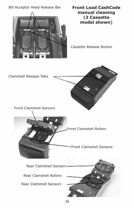
Step 1: Remove the Cassette from the Bill Acceptor.
Step 2: Open the “clamshell” by pressing the release button on the bottom of the Bill Acceptor.
Step 3: Use compressed air to blow out the feed path and crevices on the Bill Acceptor.
Step 4: Clean the rubber rollers and sensor lenses using a clean cloth dampened with ethyl or isopropyl alcohol.
Step 5: Close the clamshell securely.
Step 6: Replace the Cassette onto the Bill Acceptor and place the Bill Acceptor in the operating position.
Rear Load CashCode Manual Cleaning
Clamshell Release Button
Cassette Swivel
Clamshell Open View(sensors and rollers inside)

25
Front Load CashCode Cassette Removal
Step 1: Open the Bill Acceptor Vault.
Step 2: Hold the two cassette handles together and press the cas-sette release button, while pulling the cassette from the Bill Acceptor.
Step 3: Turn the Open/Close knob (or key if equipped with a lock) to the Open position to access the contents of the cas-sette.
Front Load CashCode Cassette Installation
Step 1: Place the cassette into the Bill Acceptor with the Cassette Release Button on the top, right side.
Step 2: Push the cassette into the Bill Acceptor until it “locks” in place.
Bill Acceptor HeadsCassette Release Buttons
Cassette Handles Drop Chute Handle
26
Bill Acceptor Head Release Bar
Cassette Release Button
Clamshell Release Tabs
Front Clamshell Rollers
Rear Clamshell Rollers
Rear Clamshell Sensors
Rear Clamshell Sensors
Front Clamshell Sensors
Front Clamshell Sensors
Front Load CashCode manual cleaning
(2 Cassette model shown)

MEI CashFlow Bill AcceptorsStep 1: Open the Bill Acceptor Vault.
Step 2: Pull the Cassette out of the Bill Acceptor by the yellow handle.
Step 3: Slide the release button away from the edge of the cas-sette to open the cassette door and access the contents of the cassette.
Step 4: To install the cassette, insert the cassette with the indica-tor arrow pointing up, until it seats into the Bill Acceptor.
Cassette door lock(if equipped)
Cassette door release button
30
Acceptor Head Release BarAcceptor Head Release Bar(Single Note Feeder)(Single Note Feeder)
Cassette Handles
Acceptor Head Release Button(Bulk Note Feeder)(Bulk Note Feeder)(Bulk Note Feeder)

3131
MEI CashFlow Manual CleaningNOTE: It is recommended that the Bill Acceptor is manually cleaned
every thirty days or every 20,000 bills, whichever occurs fi rst.
Step 1: Remove the Cassette from the Bill Acceptor.
Step 2: Remove the Acceptor “head” by pressing up on the re-lease bar while pulling outward.
Step 3: Open the clamshell by pulling the clamshell release cover toward the bill insertion throat while opening the clam-shell.
Step 4: Press the roller release button to remove the Roller Assem-bly and clean the rubber rollers (Bulk Note Feeders only).
Step 5: Clean the Sensor lenses and rollers with a damp cloth.
Bill insertion throat Clamshell release cover
Clean the sensor lenses and rollers inside the clamshell
Press in on the yellow release button Press in on the yellow release button to remove the roller assembly
(Bulk Note Feeders)

Squeeze the release tabs to remove the Bill Tray from the door
Press the Roller Assembly release button while pulling
the RollerAssembly tab outward
MEI CashFlow Manual Cleaning
Jams can be removed from this area
Clean the Roller Assembly
RollerAssembly tab
32

Clean the “Cassette Present” sensors with compressed air or a damp cotton swab
Clean the “Cassette Present” sensors with
MEI CashFlow Manual Cleaning
33

Bulk Coin Dispenser OperationsLoading Coins:
Note: See the following pages for Coin Hopper location and layout.
Step 1: Open the Coin/Note Vault Door.
Step 2: Slide the Coin Dispenser Rack fully out of the cabinet.
Step 3: Open the desired cover(s) and add coins to the hopper(s).
Warning:Warning: Loading the incorrect coin type into a Hopper WILL cause jams or failure.
Step 4: Close the covers.
Step 5: Push down on the Rack Release and push the Coin Dis-penser back into the cabinet (see next page).
Step 6: Close and lock the Coin/Note Vault Door.
Step 7: Navigate to the Coin Hopper Control Menu.
Log In > (enter code) > Cash Control > Load Cash Device> Coin Hopper Counts
Add Coins - The current number of coins will be in-creased by the amount entered in this screen
New Coin Count - The current number of coins will be erased and the amount entered will become the new count.
Step 8: Select the desired coin hopper and enter the number coins loaded.
Dumping CoinsStep 1: Open the Coin/Note Vault Door.
Step 2: Navigate to the Dump Coins menu.
Log In > (enter code) > Dump Coins
Step 3: Select the desired column(s) to dump and coins will be dispensed into the container.
Step 4: When the coin tray is full, the dump process will stop.
Remove the trayEmpty the trayRe-install the tray to continue the dump process
Step 5: Repeat steps 3 and 4 to dump all desired columns.
a)b)c)
34

1 2 3
4 5 6
7 8
Coin Receiving Tray Locations
1 2 3
4 5 6
7 8
Coin Hopper Locations
BCD Rack Release Lever
35

36
Coin Hopper Maintenance(Illustrations on next page show a BCD Model with no Dispenser,
however, the procedure is the same on both models)
Hopper Removal
Step 1: If possible, dump all coins from the Hopper before pro-ceeding.
Step 2: Pull down on the Hopper Cover Release Pin and push the Hopper Cover toward the rear of the unit.
Step 3: Lift the front of the Hopper Cover and remove the cover from the Coin Dispenser.
Step 4: Insert the “Hopper Removal Tool” in front of the Hopper and press the release tab down while shifting the Hopper toward the rear of the unit.
Step 5: Lift the Hopper out of the Coin Dispenser.
NOTE: Be careful not to pull the cable loose from the hopper as-sembly while removed from the Coin Dispenser!
Exit Sensor Cleaning
Step 1: Gently swab the Sensor lenses with a damp “Q-Tip” or damp cloth.
DO NOT USE CHEMICALS OR ABRASIVE CLEANERS!
Jam Removal:
Step 1: Turn the hopper upside-down to empty the hopper of for-eign material, incorrect coin denominations, etc...
Step 2: Rotate the “thumbwheel” at the base of the Hopper to as-sist with clearing a jam.
Hopper Replacement
Step 1: Place the Hopper into the Coin Dispenser (cable on the left side), and insure it “snaps” securely into the seat.
Step 2: Place the Hopper Removal Tool into the storage area.
Step 3: Place the Hopper Cover so the pins at the rear of the cover engage the slots in the Coin Dispenser.
Step 4: Close the Hopper Cover and pull it forward until the Hop-per Cover Release Pin engages the cover.

Hopper Cover Release Pin
Hopper Cover
Hopper Release Tool(placed in storage area)
Center the Hopper Release Tool in front of the Hop-
per and press the release tab down while shifting
the bottom of the Hopper toward the rear of the unit.
Sensor Lenses/Coin Exit Located on lower front of Hopper.
37
Thumbwheel location
To remove the Hopper:

Bill Dispenser Cassette/Coin Receiving Tray Locations
Rack Release Lever
Low Capacity (Fujitsu)
Bill Dispenser Cassettes
Low Capacity (Fujitsu)
Bill Dispenser Reject Tray
Coin Receiving Trays
1
3
5
2
4
6
1
2
3
4
2
Top view of Hopper
1 2
3 4
5 6Low Capacity
(Fujitsu)Dispenser
TouchscreenTouchscreen
BCD Hoppers
38
Coin Dispenser Coin Dispenser Rack HandleRack Handle

Step 1: Prepare the notes by fl ipping through each bundle of notes in both directions, or by using a note counter. Remove foreign objects, (staples, paper clips, tape, etc...). Remove torn or very worn notes. Straighten any folded notes.
Step 2: Stack the bills evenly in the cassette (maximum capacity is approximately 400 notes).
Step 3: Place the front and rear pressure plates in the down posi-tion, against the bills.
Step 4: Navigate to the Dispenser Control Menu.
Log In > (enter code) > Cash Control > Load Cash Device > Dispenser Counts
Add Notes - The current number of bills will be in-creased by the amount entered in this screen
New Note Count - The current number of bills will be erased and the amount entered will become the new count.
Step 5: Select the desired cassette and enter the number bills loaded.
39
Bill Dispenser Operations
Loading Bills In The Feed Cassettes(Low Capacity Dispenser)
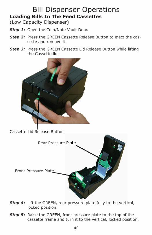
Cassette Lid Release Button
Loading Bills In The Feed Cassettes(Low Capacity Dispenser)
Step 1: Open the Coin/Note Vault Door.
Step 2: Press the GREEN Cassette Release Button to eject the cas-sette and remove it.
Step 3: Press the GREEN Cassette Lid Release Button while lifting the Cassette lid.
Step 4: Lift the GREEN, rear pressure plate fully to the vertical, locked position.
Step 5: Raise the GREEN, front pressure plate to the top of the cassette frame and turn it to the vertical, locked position.
Rear Pressure PlateRear Pressure Plate
Front Pressure PlateFront Pressure Plate
40
Bill Dispenser Operations
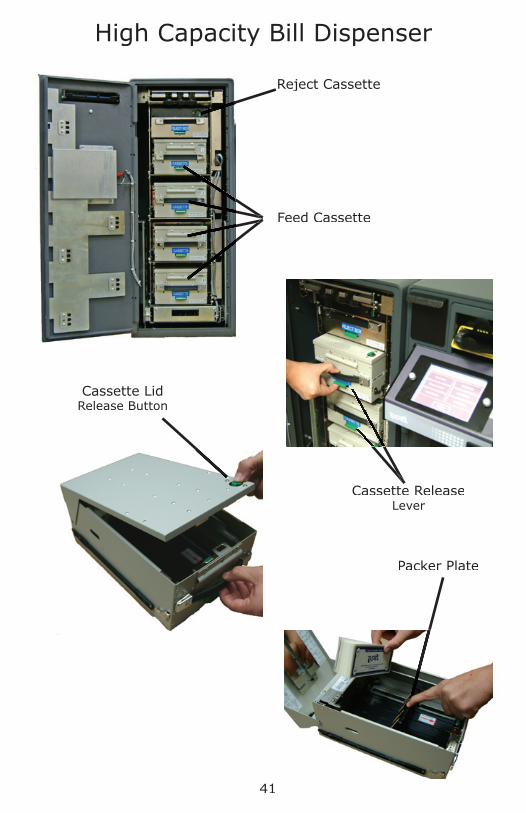
Reject Cassette
Feed Cassette
Cassette ReleaseLever
Cassette Lid Release Button
Packer Plate
High Capacity Bill Dispenser
41

Loading Bills In The Feed Cassettes (High Capacity Dispenser)
Step 1: Open the Note Vault Door.
Step 2: Lift the GREEN Cassette Release Lever while pulling the cassette to remove the cassette.
Step 3: Press the GREEN Cassette Lid Release Button while lifting the Cassette lid.
Step 4: Pull the pressure plate back to insert bills.
NOTE: If pulled fully to the rear of the cassette, the packer plate will lock in place. To release the packer plate, pull it back toward the rear of the cassette again.
Step 5: Prepare the notes by fl ipping through each bundle of notes in both directions, or by using a note counter. Remove foreign objects, (staples, paper clips, tape, etc...). Remove torn or very worn notes. Straighten any folded notes.
Step 6: Place bills evenly into the cassette (Cassette capacity is approximately 1500 ~ 1700 notes).
Step 7: Place the pressure plate against the bills.
Step 8: Navigate to the Dispenser Control Menu.
Log In > (enter code) > Cash Control > Load Cash Device > Dispenser Counts
Add Notes - The current number of bills will be in-creased by the amount entered in this screen
New Note Count - The current number of bills will be erased and the amount entered will become the new count.
Step 9: Select the desired cassette and enter the number bills loaded.
Bill Dispenser Operations
42

Bill Dispenser Operations
Removing Bills FromThe Reject Cassette
Step 1: Open the Note Vault Dooor.
Step 2: Remove the reject cassette from the Bill Dispenser.
Step 3: Remove any existing from the Reject Tray.
Step 4: Navigate to the Clear Bill Count Menu.
Log In > (enter code) > Cash Control > Clear Bill Counts > Empty Reject Compartment
Step 5: A report will be printed for verifying reject counts.
NOTE: The number of rejects on the report represents the number of reject incidents, not the number of bills. It is recommend-ed that the notes in the cassette and reject tray be counted for accurate reconciliation.
Reject Cassette Lid Release Button
(High Capacity Dispenser)
Reject Cassette Release Lever
(High Capacity Dispenser)
Reject Cassette
(High Capacity Dispenser)
Reject Tray (Low Capacity Dispenser)
43

44
End Of Day/Shift
When an End of Day is performed, all transaction information from the previous End of Day to the current End of Day, will be stored in a fi le, which can be re-printed.
Each time an End of Shift is performed, time (shift) peri-ods will be divided on the reports and activity performed on those shifts will be listed.
Typically, A current content report should be printed and ac-tual amounts in the machine verifi ed against the report.
Step 1: To prevent amounts being carried forward to the next reporting period, perform the following before performing the End Of Day (see the following pages):
Adjust Vault Contents (for discrepancies)
Move Vault Contents (For drops, change fund, etc...)
Clear Acceptors/Reject Tray
Step 2: Navigate to “End Of Day/Shift”.
Log In > (enter code) > End Of Day/Shift
Step 3: From the End Of Day/Shift screen, select “End Of Day” or “End Of Shift”.
Step 4: Select “YES” when the display prompt, “Do you really want to end the business day or shift” appears.
☞
☞
☞

45
Adjusting Vault Contents
When actual amounts of vault contents don’t match the re-ports, this function can be used to make corrections.
Step 1: Navigate to the “Adjust Vault Contents” Menu.
Log In > (enter code) > Cash Control > Adjust Vault Contents
Step 2: The user will be prompted to select a currency type (if a secondary currency is being used).
Step 3: The user will be prompted to select from one of the follow-ing vaults:
Drop - will add/subtract from the Vault Drop amounts.
Vault - will add/subtract from the Main Vault/Reserve Change Fund amounts.
Courier Tray - will add/subtract from the Courier Tray amounts.
Step 4: After selecting the currency type, the user will be prompt-ed to select the type of activity:
Positive (Deposit)
Negative (Withdrawal)
Step 5: The amount to be added or subtracted can be entered.
Step 6: Verify the amount of the adjustment.
Step 7: Select “Done” to return to the “Cash Control” menu.
☞

46
Moving Vault Contents
Performing this function will cause the reports to refl ect funds were moved FROM or TO a vault.
Step 1: Navigate to the “Move Vault Contents” Menu.
Log In > (enter code) > Cash Control > Move Vault Contents
Step 2: The user will be prompted to select a currency type (if a secondary currency is being used).
Step 3: The user will be prompted to select from one of the follow-ing vaults to move the amount FROM:
Outside - Funds from an outside source are being put intoput into the unit.
Drop - Amounts shown as Vault Drops on the reports are being moved.
Reserve Change Fund - The amounts on the reports that are the availabe funds in the machine.
Courier Tray - Amounts shown in the Courier Tray are being moved.
NOTE: If any of the above selections do not appear, the vault amount is currently zero.
Step 4: The user will be prompted to select where the amount will be moved TO:
Outside – Reports will refl ect the amount was re-moved from the unit.
Drop – Will add to the existing Vault Drop amount on the reports.
Reserve Change Fund - Amounts that are the avai-labe for store operations.
Courier Tray - Will add to the existing Courier Tray amounts on the reports.
Continued on next page
☞

47
Moving Vault Contents(Continued)
Step 5: The user will be prompted to select one of the following options:
Everything - Will transfer the total amount reported in the “move from” location to the “move to” location.
This prompt appears when DROP or VAULT was select-ed as the “move from” location.
Something Specifi c – Will prompt the user to select the currency type and enter the amount to be trans-ferred to the “move to” location.
This prompt appears when DROP or VAULT was select-ed as the “move from”.
Step 6: Verify the amount of the move.
NO - Will exit the “Move Vault Contents” and restart at step 4.
Step 7: Select “Done” to return to the “Cash Control” menu.
48
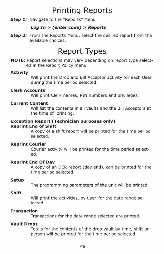
Printing ReportsStep 1: Navigate to the “Reports” Menu.
Log In > (enter code) > Reports
Step 2: From the Reports Menu, select the desired report from the available choices.
Report TypesNOTE: Report selections may vary depending on report type select-
ed in the Report Policy menu.
ActivityWill print the Drop and Bill Acceptor activity for each User during the time period selected.
Clerk AccountsWill print Clerk names, PIN numbers and privileges.
Current ContentWill list the contents in all vaults and the Bill Acceptors at the time of printing.
Exception Report (Technician purposes only)Reprint End of Shift
A copy of a shift report will be printed for the time period selected.
Reprint CourierCourier activity will be printed for the time period select-ed.
Reprint End Of DayA copy of an DER report (day end), can be printed for the time period selected.
SetupThe programming parameters of the unit will be printed.
ShiftWill print the activities, by user, for the date range se-lected.
TransactionTransactions for the date range selected are printed.
Vault DropsTotals for the contents of the drop vault by time, shift or person will be printed for the time period selected.

Adding A Clerk
Step 1: Navigate to the “Clerk Accounts” menu.
Log In > (enter code) > More > Clerk Accounts > Add
Step 2: Enter the new Clerk’s PIN (4-9 numbers).
Step 3: Verify the new Clerk’s PIN by re-entering the number.
Step 4: Enter the new Clerk’s Name (2-8 characters) and press “Done”.
Step 5: Edit the Clerk’s privileges
Step 6: Select “Save”.
Step 7: Select “Go Back” until the Main Screen is displayed.
Name (2 to 8 characters) PIN (4 to 9 numbers) Identifi cation KeyEnd Business Day (Y/N)End Shift (Y/N)Print Reports (Y/N) LanguageChange own PIN (Y/N)
49

50
Troubleshooting
BILL ACCEPTORS:
The Bill Acceptor Needs Cleaning:Press “Done” to remove the reminder from the screen.
Clean the Bill Acceptor by the recommended procedure (see “Cleaning” in the Bill Acceptor section of this manual).
The reminder appears every 4 hours until a “Clear all odometers” is performed.
After cleaning has been performed, you may reset the bill counter (odometer) by performing a “Clear all odometers”.
Log In > More > Maintenance > Bill Acceptors > Clean Acceptors > Clear all odometers
Bill Acceptor Will Not Throat Bills:Remove and reinstall the cassette.
Inspect the cassette for damage.
Remove the cassette, open the clamshell door and check for jams or obstructions. Insure the clamshell door is closed properly. Clean all Sensors and Rollers.
Unplug the unit from the wall socket (or remove the Fuse), wait 5 seconds, then re-apply AC power.
Bills Jam/Rejects BillsRemove and reinstall cassette.
Inspect the cassette for signs of damage or abuse.
Inspect the quality of bills being rejected\jamming.
Open the “clamshell” and check for obstructions or debris.
Remove the roller assembly and check for jams or obstruc-tions. (Bulk Note Feeders only).
Clean the rollers and optical sensors with a damp cloth and mild detergent (do not use solvents or ammonia based prod-ucts.)
LED Is Not IlluminatedRemove and re-install the Bill Acceptor Head.
1)
2)
3)
1)
2)
3)
4)
1)
2)
3)
4)
5)
6)
1)

BILL DISPENSING:
Dispense Selection Does Not Appear:There are no bills in the Cassette. Perform a Load Dispenser Counts from the Load Cash Device menu.
Log In > Cash Control > Load Cash Device > Load Dispenser Counts
The selection is an amount higher than the User’s Vending Limit.
The Dispense Failed:Remove and reinstall the cassettes.
Insure bills are properly loaded in the cassettes.
Check for jammed notes on the feed path.
COIN DISPENSING:
Coin Jam:Remove the hopper to free jammed coins.
“N/A” Appears Next To Selection DescriptionUnplug the unit from the wall socket (or remove the Fuse), wait 5 seconds, then re-apply AC power.
Insure Coins are loaded in the Hopper.
Check for coin jams in the Hopper
Clean the sensors.
Nothing Dispensable:Unplug the unit from the wall socket (or remove the Fuse), wait 5 seconds, then re-apply AC power.
Insure Coins are loaded in the Hopper.
Log In > Cash Control > Load Cash Device > Coin Hopper Counts
Selections Don’t Appear in the “Dispense Coin” menu
There are no Coins in the Hopper. Perform a “New Coin Count” or “Add Coins” from the Coin Control Menu.
The selection is an amount higher than the User’s Vending Limit.
1)
2)
1)
2)
3)
1)
1)
2)
3)
4)
1)
2)
1)
2)
Troubleshooting
51

DATAKEY:
DataKey not functioningCheck the User’s account privileges. Insure the DataKey is assigned to the User’s account (last 4 digits of the DataKey will be displayed in the Account privileges).
If “Not Trained” is displayed in the User’s account, no DataKey is assigned to the User.
From “Diagnostics” in the Maintenance Menu, perform a DataKey test using a known working DataKey.
If no response when the Datakey is inserted and turned (other DataKeys are working/respond), the DataKey may be defective.
DISPLAY:
No Display:Press the reset button, located under the Control Panel.
Insure AC power is present at the wall socket.
Check the 3 amp slow-blow fuse, located under the Control Panel.
Multiple Images/Slow Reaction:Press the reset button, located under the Control Panel.
Replace the Screen Protector.
PRINTER:
Printer Wont Print/No Selections Appear In The Reports Menu:
Perform a Printer Reset:
Disconnect AC Power from the unit.Hold the paper feed button down and re-apply AC power.When paper begins to feed, release the paper feed button.Unplug the unit from the wall socket (or remove the Fuse), wait 5 seconds, then re-apply AC power to stop the test printing.
1)
2)
1)
2)
3)
1)
2)
1)
a)b)
c)
d)
Troubleshooting
52

TOUCHSCREEN:
Code Entry Diffi cultControl Panel Selections Not Responding
Perform a power reset or press the reset button under the Control Panel.
Replace the Screen Protector
TUBE VENDING:
Column Selections Don’t Appear In The Vend Tube Menu
The columns may be empty.
The tube amount assigned to the column may be higher than user’s Vending Limit.
VAULT DOORS:
The Coin/Note/Drop/Acceptor Vault Has Been Open Too Long, Please Close It:
This error message is displayed when the unit detects a door has been unlocked for more than 5 minutes.
Close and lock the appropriate door.
Select “Cancel”. A prompt to enter the Manager code will be displayed. Entering the Manager code will temporarily return to the Main screen. The error message will return after 5 minutes if the door remains unlocked.
NOTE: After the Manager Code entry has been used to bypass the error message 3 times, the error will not return.
To Cancel Door Opening In ProgressPerforming a “Secure All Vaults” will stop all door opening procedures that are in progress.
Navigate to the “Open Vault” Menu.
Log In > (enter code) > Open Vault
Select “Secure All Vaults”.
The Display will show “All vaults have been secured”.
1)
2)
1)
2)
1)
2)
3)
☞
1)
2)
3)
Troubleshooting
53

Combination LockBattery Replacement
Battery Cover Handle
Combination Lock Keypad
Repeated beeping during opening or a continuous fl ashing LED indi-cates a low battery condition.
The battery should be replaced immediately with a 9vdc alkaline battery.
LED
Step 1: Gently pull down on the Battery Cover Handle to remove the Battery Cover.
Step 2: Remove and replace the battery.
Step 3: Place the battery cover so that one end of the cover is in-serted into the Combination Lock body fi rst, then snap the opposite end into place.
54

Screen Protector ReplacementStep 1: Disconnect AC power from the unit.
Step 2: Unscrew the (2) securing knobs that secure the Bezel to the front of the Control Panel and remove the Bezel.
Step 3: Peel the existing Screen Protector away from the Face-plate.
Step 4: When the Screen Protector is peeled off the Faceplate, some adhesive residue may remain. Remove this residue by “dry rubbing”, prior to installing the replacement Screen Protector.
Step 5: Peel the adhesive backing and fi lm from BOTH sides of the Screen Protector.
Step 6: Align the screen protector in the Faceplate and apply it evenly across the surface of the Faceplate.
Step 7: Place the removable Bezel onto the Faceplate and secure it with the (2) securing knobs.
55
SecuringKnobs
Removable Bezel
Screen Protector
Faceplate

Paper Specifi cations (built in printers)
Thermal paperPaper width - 79.5 mm (3.13 inches)Roll diameter - 80 mm or less (3.15 inches)Thickness - 65 micron (0.065 mm)
Tidel Part Numbers:
Cleaning Cards - CashCode
644-0107-005S - Qty = 5644-0107-100S - Qty = 100644-0107-500S - Qty = 500
Cleaning Cards - JCM
644-0107-025S - Qty = 5644-0107-120S - Qty = 100644-0107-520S - Qty = 500
Cleaning Cards - MEI
644-0107-035S - Qty = 5644-0107-130S - Qty = 100644-0107-530S - Qty = 500
Paper - Integrated (built in) Printers
644-0088-003S - Qty = 16 rolls644-0088-004S - Qty = 8 rolls
Screen Protector (mounted under Control Panel Bezel)
205-0541-001S - Qty = 5
Screen Protector (static fi lm)
205-0535-001S - Qty = 10
Tool - Hopper Removal
205-2137-001S - Qty = 1
Vend Tubes
201-3086-001S - Qty = 100
56

57
Manager Menu MapManager Screen 1
Cash ControlAdjust Vault ContentsClear Bill Count
Clear AcceptorsEmpty Reject Tray
Confi gure Dispense ChoicesCoin Hopper Control
Set ChoicesSetup Hoppers
Confi gure DispenserCassette Confi gurationConfi gure Dispense Choices
Combo DispenseSelect CoinsSelect Bills
Load Cash DeviceCoin Hopper Counts
Add CoinsNew Coin Count
Dispenser CountsAdd NotesNew Note Count
Drops To Courier TrayMove Vault Contents
Change PINClean ScreenDump CoinsEnd Of Day/ShiftOpen Vault
Acceptor/Coin/Note/Drop/Storage Vault Secure All Vaults
Reports(Select from available choices)
Screen ContrastMore (To Manager Screen 2)
Manager Screen 1
58
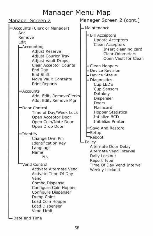
Manager Menu MapManager Screen 2Manager Screen 2
Accounts (Clerk or Manager)AddRemoveEdit
Accounting Adjust ReserveAdjust Courier TrayAdjust Vault DropsClear Acceptor CountsEnd DayEnd ShiftMove Vault ContentsPrint Reports
AccountsAdd, Edit, RemoveClerksAdd, Edit, Remove Mgr
Door Control Time of Day/Week LockOpen Acceptor DoorOpen Coin/Note Door Open Drop Door
IdentityChange Own PinIdentifi cation KeyLanguageName
PIN
Vend ControlActivate Alternate VendActivate Time Of Day VendCombo DispenseConfi gure Coin HopperConfi gure DispenserDump CoinsLoad Coin HopperLoad DispenserVend Limit
Date and Time
Manager Screen 2 (cont.)Manager Screen 2 (cont.)
Maintenance
Bill AcceptorsUpdate AcceptorsClean Acceptors
Insert cleaning cardClear OdometersOpen Vault for Clean
Clean HoppersDevice RevisionDevice StatusDiagnostics
Cup LED’sCup SensorsDatakeyDispenserDoorsFlashcardHopper StatisticsIntialize BCDInitialize Printer
Save And RestoreSetupReboot
PolicyAlternate Door DelayAlternate Vend IntervalDaily LockoutReport TypeTime Of Day Vend IntervalWeekly Lockout

59
SEN
TIN
EL
PRO
DU
CT L
INE W
ARRAN
TY
LIM
ITATIO
NS O
F W
ARRAN
TIE
S A
ND
REM
ED
IES F
OR P
RO
DU
CTS D
ELI
VERED
TO
LO
CATIO
NS W
ITH
IN T
HE U
NIT
ED
STA
TES A
ND
CAN
AD
A
A. L
IMIT
ED
WARRAN
TIE
S -
SU
BJE
CT T
O T
HE T
ERM
S S
ET F
ORTH
BELO
W,
TID
EL
EN
GIN
EERIN
G,
L.P.
, A T
EXAS L
IMIT
ED
PARTN
ERSH
IP (
“Tid
el”)
WARRAN
TS O
NLY
TO
TH
E P
ERSO
N O
R E
NTIT
Y
WH
O P
URCH
ASES T
HE P
RO
DU
CT D
IRECTLY
FRO
M T
IDEL
OR F
RO
M A
TID
EL
AU
TH
ORIZ
ED
RESELL
ER TH
AT,
should
the
Product
pro
ve d
efec
tive
by
reas
on o
f im
pro
per
work
man
ship
or
mat
e-rial
s, T
idel
will
rep
lace
all
nec
essa
ry e
lect
rica
l, e
lect
ronic
and m
echan
ical
par
ts w
ith n
ew o
r fa
ctory
rec
onditio
ned
rep
lace
men
t par
ts,
without
a ch
arge
for
the
par
ts for
tw
elve
(12)
month
s,
and w
ithout
a ch
arge
for
the
auth
orize
d s
ervi
ce d
eale
r la
bor
for
nin
ety
(90)
day
s af
ter
the
origin
al inst
alla
tion o
f th
e Pr
oduct
, PR
OVID
ED
, H
OW
EVER,
TH
AT I
N N
O E
VEN
T S
HALL
TH
IS L
IM-
ITED
WARRAN
TY E
XTEN
D F
OR M
ORE T
HAN
EIG
HTEEN
(18)
MO
NTH
S A
FTER T
HE D
ATE T
HE P
RO
DU
CT I
S S
HIP
PED
FRO
M T
IDEL’
S F
ACTO
RY I
N C
ARRO
LLTO
N,
TEXAS.
It
shal
l be
Tid
el’s
sole
dec
isio
n w
het
her
to u
se n
ew,
fact
ory
, re
conditio
ned
or
repla
cem
ent
par
ts in a
ny
such
rep
air
or
repla
cem
ent.
TH
E R
EM
ED
IES D
ESCRIB
ED
HEREIN
SH
ALL
BE T
HE S
OLE
, EXCLU
SIV
E A
ND
O
NLY
REM
ED
IES O
F D
IRECT B
UYER A
ND
EN
D U
SER F
OR B
REACH
OF
TH
IS L
IMIT
ED
WARRAN
TY.
B. D
ISCLA
IMER O
F W
ARRAN
TIE
S -
TID
EL
DIS
CLA
IMS A
NY W
ARRAN
TY W
HATSO
EVER A
ND
TH
E L
IMIT
ED
WARRAN
TIE
S C
ON
TAIN
ED
HEREIN
WIL
L BE V
OID
OR V
OID
ABLE
BY T
IDEL
IF:
(i)
th
e Pr
oduct
or
any
par
ts,
incl
udin
g,
without
limitat
ion,
its
elec
tric
al,
elec
tronic
or
mec
han
ical
par
ts,
spec
ifi ca
lly incl
udin
g a
ll bill
acc
epto
rs a
nd d
ispen
sing m
odule
s, h
ave
bee
n inst
alle
d,
re-
loca
ted,
alte
red,
repai
red o
r se
rvic
ed b
y an
y in
div
idual
or
oth
er e
ntity
not
auth
orize
d b
y Tid
el t
o p
rovi
de
such
ser
vice
s; (
ii) t
he
serial
num
ber
on t
he
Product
or
any
par
ts h
ave
bee
n a
lter
ed
or
rem
oved
; (i
ii) t
he
Product
or
any
par
ts h
ave
bee
n s
ubje
cted
to a
ccid
ent,
mis
use
, ab
use
, or
neg
ligen
ce;
(iv)
the
Product
or
any
of its
par
ts h
ave
bee
n u
sed o
r oper
ated
contr
ary
to o
r in
vi
ola
tion o
f th
e in
stru
ctio
ns,
war
nin
gs,
or
man
ual
s ac
com
pan
ying t
he
Product
or
any
of its
par
ts,
incl
udin
g w
ithout
limitat
ion t
he
failu
re t
o t
imel
y or
pro
per
ly c
lean
the
Product
or
any
of
its
par
ts o
r to
tim
ely
or
pro
per
ly p
erfo
rm a
ny
pre
venta
tive
mai
nte
nan
ce o
f th
e Pr
oduct
or
any
of its
par
ts;
or
(v)
the
Product
is
not
connec
ted t
o a
ded
icat
ed,
gro
unded
ele
ctrica
l outlet
or
inst
alle
d w
ith a
lin
e co
nditio
ner
appro
ved b
y Tid
el.
Par
ts t
hat
are
consi
der
ed c
onsu
mab
le (
incl
udin
g,
but
not
limited
to,
such
as
printe
r pap
er,
dip
stic
ks,
scre
en p
rote
ctors
, ve
nd t
ubes
, an
d
enve
lopes
) ar
e not
incl
uded
in t
his
lim
ited
war
ranty
exc
ept
to t
he
exte
nt
that
thes
e item
s ar
e sh
ipped
in n
ew,
pro
per
work
ing c
onditio
n fro
m t
he
Tid
el F
acto
ry w
ith t
he
Product
. This
lim
ited
w
arra
nty
does
not
cove
r an
y cu
rren
cy jam
in a
ny
mec
han
ism
that
is
a par
t of th
e Pr
oduct
. TH
E L
IMIT
ED
WARRAN
TIE
S S
TATED
HEREIN
IN
CLU
DE P
ARTS A
ND
LABO
R O
NLY
AS S
ET F
ORTH
IN
PA
RAG
RAPH
A A
BO
VE A
ND
EXCLU
DE A
LL O
TH
ER W
ARRAN
TIE
S,
EXPR
ESS O
R I
MPL
IED
, IN
CLU
DIN
G W
ARRAN
TIE
S O
F M
ERCH
AN
TABIL
ITY O
R F
ITN
ESS F
OR A
PARTIC
ULA
R P
URPO
SE,
RELA
T-IN
G T
O T
HE U
SE O
R P
ERFO
RM
AN
CE O
F TH
E P
RO
DU
CT A
ND
TH
E P
ARTS,
WH
ETH
ER O
R N
OT P
URPO
SES O
R S
PECIF
ICATIO
NS A
RE D
ESCRIB
ED
OR P
RO
VID
ED
BY T
IDEL
WIT
H R
ESPE
CT T
O
TH
E P
RO
DU
CT O
R P
ARTS.
C. L
IMIT
ATIO
NS O
F REM
ED
IES -
TID
EL’
S L
IABIL
ITY T
O D
IRECT B
UYER A
ND
TO
EN
D U
SER,
FOR A
NY C
AU
SE W
HATSO
EVER,
AN
D R
EG
ARD
LESS O
F TH
E F
ORM
OF
ACTIO
N,
WH
ETH
ER I
N
CO
NTRACT O
R I
N T
ORT (
INCLU
DIN
G N
EG
LIG
EN
CE A
CTIO
NS),
OR O
TH
ERW
ISE,
ARIS
ING
IN
CO
NN
ECTIO
N W
ITH
TH
E P
RO
DU
CT,
PARTS O
R T
HE F
OREG
OIN
G L
IMIT
ED
WARRAN
TIE
S S
HALL
BE L
IMIT
ED
TO
TH
E C
OST O
F REPA
IR A
ND
REPL
ACEM
EN
T O
F TH
E P
RO
DU
CT O
R P
ARTS I
N A
CCO
RD
AN
CE W
ITH
TH
E L
IMIT
ED
WARRAN
TIE
S.
TID
EL
SH
ALL
NO
T B
E L
IABLE
FO
R S
PECIA
L,
INCID
EN
TAL,
IN
DIR
ECT O
R C
ON
SEQ
UEN
TIA
L D
AM
AG
ES I
NCLU
DIN
G,
BU
T N
OT L
IMIT
ED
TO
, D
AM
AG
E O
R L
OSS O
F O
TH
ER P
RO
PERTY O
R E
QU
IPM
EN
T, L
OSS O
F PR
OFI
TS O
R R
EVEN
UE,
LOSS O
F SAVIN
GS,
LOSS O
F O
R I
NABIL
ITY T
O U
SE O
F TH
E P
RO
DU
CT O
R A
SSO
CIA
TED
EQ
UIP
MEN
T, C
OST O
F CAPI
TAL,
CO
ST O
F PU
RCH
ASED
OR R
EPL
ACEM
EN
T P
ARTS O
R E
QU
IPM
EN
T,
LOSS O
F O
PPO
RTU
NIT
Y, L
OSS O
F BU
SIN
ESS,
DO
WN
TIM
E,
INJU
RY T
O P
RO
PERTY,
PERSO
NAL
INJU
RY,
OR A
NY S
PECIA
L, I
NCID
EN
TAL,
IN
DIR
ECT O
R C
ON
SEQ
UEN
TIA
L D
AM
AG
ES A
RIS
ING
IN
CO
NN
ECTIO
N W
ITH
CLA
IMS O
F TH
IRD
PARTIE
S.
D. I
NSPE
CTIO
N O
F TH
E P
RO
DU
CT O
R P
ARTS;
TIM
E L
IMIT
FO
R C
ERTA
IN C
LAIM
S -
Direc
t Buye
r an
d E
nd U
ser
are
resp
onsi
ble
for
insp
ecting a
nd s
hal
l in
spec
t th
e Pr
oduct
and a
ny
par
ts u
pon
rece
ipt
and s
hal
l notify
Tid
el a
t 2025 W
. Bel
tlin
e Road
#114,
Car
rollt
on,
Texa
s 75006-6
453 in w
riting b
y ce
rtifi
ed m
ail, r
eturn
rec
eipt
reques
ted (
post
age
pre
pai
d,
dep
osi
ted w
ith t
he
United
Sta
tes
Post
al S
ervi
ce)
of an
y cl
aim
s, incl
udin
g c
laim
s fo
r bre
ach o
f lim
ited
war
ranties
, w
ithin
thirty
(30)
day
s af
ter
the
Direc
t Buye
r or
End U
ser
dis
cove
rs o
r sh
ould
hav
e dis
cove
red t
he
fact
s upon w
hic
h t
he
clai
m is
bas
ed.
The
failu
re t
o g
ive
writt
en n
otice
of a
clai
m t
o T
idel
within
this
tim
e per
iod s
hal
l co
nst
itute
a w
aive
r an
d r
elin
quis
hm
ent
of su
ch c
laim
.
E. R
EG
ISTRATIO
N O
F TH
E P
RO
DU
CT -
The
regis
trat
ion c
ard e
ncl
ose
d w
ith t
he
Product
must
be
mai
led b
y th
e D
irec
t Buye
r (i
f th
e Pr
oduct
is
sent
from
the
Tid
el F
acto
ry t
o t
he
Direc
t Buye
r)
or
by
End U
ser
(if th
e Pr
oduct
is
sent
from
the
Tid
el F
acto
ry t
o t
he
End U
ser)
to T
idel
Engin
eering,
L.P.
, 2025 W
. Bel
tlin
e Road
#114,
Car
rollt
on,
Texa
s 7
5006,
within
ten
(10)
day
s af
ter
the
dat
e of origin
al inst
alla
tion o
f th
e Pr
oduct
. I
f th
e re
gis
trat
ion c
ard is
not
on fi le
at
Tid
el,
the
inst
alla
tion d
ate
will
be
pre
sum
ed t
o b
e th
irty
(30)
day
s af
ter
the
Product
is
ship
ped
fro
m t
he
Tid
el F
acto
ry.
F. LI
MIT
ATIO
N O
F LI
ABIL
ITY -
The
limited
war
ranties
of Tid
el s
hal
l be
subje
ct in a
ll re
spec
ts t
o t
he
limitat
ions,
dis
clai
mer
s, a
nd e
xclu
sions
set
fort
h h
erei
n.
No a
ctio
n,
regar
dle
ss o
f fo
rm,
aris
ing o
ut
of th
is lim
ited
war
ranty
may
be
com
men
ced m
ore
than
one
(1)
year
aft
er t
he
cause
of ac
tion h
as o
ccurr
ed.
G. C
HO
ICE O
F LA
WS;
VEN
UE -
This
docu
men
t sh
all be
const
rued
, in
terp
rete
d a
nd e
nfo
rced
by
apply
ing t
he
law
of th
e st
ate
of Te
xas
and w
ithout
apply
ing p
rinci
ple
s of co
nfl ic
ts o
f la
ws
and
without
giv
ing r
egar
d t
o a
ny
inte
rnat
ional
conve
ntion for
the
sale
of goods.
The
pro
visi
ons
stat
ed in t
his
docu
men
t sh
all be
enfo
rced
agai
nst
Direc
t Buye
r an
d E
nd U
ser
to t
he
max
imum
ex
tent
per
mitte
d u
nder
applic
able
law
. All
dis
pute
s ar
isin
g h
ereu
nder
shal
l be
subm
itte
d t
o a
sta
te o
r fe
der
al c
ourt
of co
mpet
ent
jurisd
iction w
ithin
Dal
las
County
, Sta
te o
f Te
xas.
For
the
nam
e of
your
nea
rest
Tid
el s
ervi
ce d
eale
r or
toco
nta
ct T
idel
about
a cl
aim
or
oth
erw
ise,
conta
ct
972-4
84-3
358
(To
ll Fr
ee:
1-8
00-6
78-7
577)
Tid
el E
ngin
eering,
2025 W
. Bel
tlin
e Road
#114
Car
rollt
on,
Texa
s 75006-6
453

2025 W. Belt Line Rd, #114Carrollton TX 75006
1-800-678-7577 (phone)972-484-1014 (fax)[email protected]