Sensing and Control for Robust Grasping -...
102
Transcript of Sensing and Control for Robust Grasping -...


Sensing and Control for Robust GraspingWith Simple Hardware
A dissertation presented
by
Leif Patrick Jentoft
to
The Harvard School of Engineering and Applied Science
in partial fulfillment of the requirements
for the degree of
Doctor of Philosophy
in the subject of
Engineering Sciences
Harvard University
Cambridge, Massachusetts
May 2014

c© 2014 Leif Patrick Jentoft
All rights reserved.

Dissertation Advisor:Robert D. Howe
Author:Leif Patrick Jentoft
Sensing and Control for Robust GraspingWith Simple Hardware
Abstract
Robots can move, see, and navigate in the real world outside carefully structured factories, but
they cannot yet grasp and manipulate objects without human intervention. Two key barriers are
the complexity of current approaches, which require complicated hardware or precise perception
to function effectively, and the challenge of understanding system performance in a tractable
manner given the wide range of factors that impact successful grasping. This thesis presents
sensors and simple control algorithms that relax the requirements on robot hardware, and a
framework to understand the capabilities and limitations of grasping systems.
The sensors and algorithms build on the recent success of underactuated hands, which use
passive mechanics to adapt to object shape and position rather than trying to perceive a precise
model of the object and control the grasp to match it. They include piezoelectric contact sensors
that expand the range of positioning offsets the hand can tolerate, joint-angle sensors for compliant
flexure joints that enable full-finger contact detection and determine object shape, and tactile
sensors based on MEMS barometers that enable the hand to more gently adapt to object shape.
The framework poses the grasping problem as "overcoming variation." It is not tractable to
list all sources of variation that might potentially affect a grasp; a small subset are dominant
in each context (such as object geometry or object mass), but listing them explicitly allows the
clear comparison of different systems, and allows the contributions of different subsystems to
be compared and understood in the same terms. This motivates a design methodology centered
around the idea of a template grasp that serves as a reference around which local variation can be
understood and analyzed to determine a "basin of attraction" within which a grasp is successful;
this variation budget encompasses object variation, perception variation, and robot positioning
errors. Increasing the size of this variation budget then serves as a target for system design.
iii

Contents
Abstract . . . . . . . . . . . . . . . . . . . . . . . . . . . . . . . . . . . . . . . . . . . . . . . . iiiAcknowledgments . . . . . . . . . . . . . . . . . . . . . . . . . . . . . . . . . . . . . . . . . vi
1 Introduction 1
2 Piezo Contact Sensors and Simple Alignment 62.1 Grasp Planning and Online Correction . . . . . . . . . . . . . . . . . . . . . . . . . . 62.2 Piezofilm Contact Sensor . . . . . . . . . . . . . . . . . . . . . . . . . . . . . . . . . . . 82.3 Grasp Alignment Algorithm . . . . . . . . . . . . . . . . . . . . . . . . . . . . . . . . . 102.4 Materials and Methods . . . . . . . . . . . . . . . . . . . . . . . . . . . . . . . . . . . . 112.5 Experimental Results . . . . . . . . . . . . . . . . . . . . . . . . . . . . . . . . . . . . . 152.6 Discussion . . . . . . . . . . . . . . . . . . . . . . . . . . . . . . . . . . . . . . . . . . . 162.7 Conclusions . . . . . . . . . . . . . . . . . . . . . . . . . . . . . . . . . . . . . . . . . . 18
3 Joint-Angle Sensor for Flexure Joints 193.1 Introduction . . . . . . . . . . . . . . . . . . . . . . . . . . . . . . . . . . . . . . . . . . 193.2 Phototransistor Flexure Sensing . . . . . . . . . . . . . . . . . . . . . . . . . . . . . . . 21
3.2.1 Design . . . . . . . . . . . . . . . . . . . . . . . . . . . . . . . . . . . . . . . . . 213.2.2 Experimental Evaluation . . . . . . . . . . . . . . . . . . . . . . . . . . . . . . 223.2.3 Discussion . . . . . . . . . . . . . . . . . . . . . . . . . . . . . . . . . . . . . . . 23
3.3 Optical Fiber Flexure Sensing . . . . . . . . . . . . . . . . . . . . . . . . . . . . . . . . 253.3.1 Parameterizing Joint Deflection . . . . . . . . . . . . . . . . . . . . . . . . . . . 253.3.2 Sensor Design . . . . . . . . . . . . . . . . . . . . . . . . . . . . . . . . . . . . . 273.3.3 Characterization . . . . . . . . . . . . . . . . . . . . . . . . . . . . . . . . . . . 303.3.4 Discussion . . . . . . . . . . . . . . . . . . . . . . . . . . . . . . . . . . . . . . . 31
3.4 Conclusion . . . . . . . . . . . . . . . . . . . . . . . . . . . . . . . . . . . . . . . . . . . 34
4 Contact and Object Geometry from Compliant Joints with Angle Sensors 354.1 Background: Gentle Contact Interactions . . . . . . . . . . . . . . . . . . . . . . . . . 354.2 Contact Detection with Compliant Joints . . . . . . . . . . . . . . . . . . . . . . . . . 364.3 Determining Object Geometry . . . . . . . . . . . . . . . . . . . . . . . . . . . . . . . 38
4.3.1 Object Geometry from Space Sweeping . . . . . . . . . . . . . . . . . . . . . . 394.3.2 Assumptions . . . . . . . . . . . . . . . . . . . . . . . . . . . . . . . . . . . . . 39
iv

4.3.3 Algorithm . . . . . . . . . . . . . . . . . . . . . . . . . . . . . . . . . . . . . . . 394.3.4 Experimental Validation . . . . . . . . . . . . . . . . . . . . . . . . . . . . . . . 414.3.5 Discussion . . . . . . . . . . . . . . . . . . . . . . . . . . . . . . . . . . . . . . . 43
4.4 Conclusion . . . . . . . . . . . . . . . . . . . . . . . . . . . . . . . . . . . . . . . . . . . 46
5 MEMS Barometer Tactile Sensors and Contact-Relative Control 475.1 Compensating for Alignment Errors . . . . . . . . . . . . . . . . . . . . . . . . . . . . 475.2 Limits to Compliance . . . . . . . . . . . . . . . . . . . . . . . . . . . . . . . . . . . . . 485.3 Tactile Sensors from MEMS Barometers . . . . . . . . . . . . . . . . . . . . . . . . . . 515.4 Experiments . . . . . . . . . . . . . . . . . . . . . . . . . . . . . . . . . . . . . . . . . . 53
5.4.1 Materials and Methods . . . . . . . . . . . . . . . . . . . . . . . . . . . . . . . 535.4.2 Experiment 1 - Compliance . . . . . . . . . . . . . . . . . . . . . . . . . . . . . 555.4.3 Experiment 2 - Light Object . . . . . . . . . . . . . . . . . . . . . . . . . . . . . 565.4.4 Experiment 3 - Controlling Gentle Contacts . . . . . . . . . . . . . . . . . . . 59
5.5 Discussion . . . . . . . . . . . . . . . . . . . . . . . . . . . . . . . . . . . . . . . . . . . 605.6 Conclusions . . . . . . . . . . . . . . . . . . . . . . . . . . . . . . . . . . . . . . . . . . 61
6 Grasping Systems & Variation 636.1 Posing the Grasping Problem as Overcoming Variation . . . . . . . . . . . . . . . . . 64
6.1.1 System Breakdown . . . . . . . . . . . . . . . . . . . . . . . . . . . . . . . . . . 646.1.2 A Selected Review of Robot Grasping in Terms of Variation . . . . . . . . . . 65
6.2 Template Grasps and Variation Budgets . . . . . . . . . . . . . . . . . . . . . . . . . . 686.3 Example Grasping Skills . . . . . . . . . . . . . . . . . . . . . . . . . . . . . . . . . . . 72
6.3.1 Surface Grasp Skill . . . . . . . . . . . . . . . . . . . . . . . . . . . . . . . . . . 736.3.2 Pinch Grasp Skill . . . . . . . . . . . . . . . . . . . . . . . . . . . . . . . . . . . 756.3.3 Fingerwalk Manipulation . . . . . . . . . . . . . . . . . . . . . . . . . . . . . . 76
6.4 Conclusion . . . . . . . . . . . . . . . . . . . . . . . . . . . . . . . . . . . . . . . . . . . 77
7 Conclusion and Future Directions 797.1 Summary . . . . . . . . . . . . . . . . . . . . . . . . . . . . . . . . . . . . . . . . . . . . 797.2 Specific Contributions . . . . . . . . . . . . . . . . . . . . . . . . . . . . . . . . . . . . 807.3 Future Directions . . . . . . . . . . . . . . . . . . . . . . . . . . . . . . . . . . . . . . . 80
References 83
v

Acknowledgments
Like all good stories, it starts with people. Well, people and robots, but they said "choose people
over project" when I asked for advice on grad school, and I am convinced the advice is true
despite being incredibly fortunate in both regards. I would not be here without the colleagues
and friends that have inspired, taught, stretched, supported, and worked with me through the
ups, downs, problem sets, paper deadlines, and late nights of takeout and loud techno.
First, I’d like to thank my adviser Rob Howe – your dedication to encouraging students to
think for themselves, to take initiative, and to solve important problems have made this time
an incredible journey. Working with you I’ve learned an immense amount about the research
process, where to target it, and how to present it clearly ("what’s the take-away?"), as well as
about the softer skills of networking, management, and establishing collaborations. Your fairness
and optimism have made it easy to focus on the important stuff – the research itself – and I am
continually amazed at your ability to see win-win situations when conflicts arise to realign people
towards common goals.
I also thank the members of the hands team. Yaro - for your inspiring curiosity, for many
productive disagreements, and a great time launching TakkTile together. Qian - for being a great
colleague and extraordinarily conscientious; I’m thrilled the project will be in your capable hands
after I leave. Frank - for always being willing to lend an ear, for inspiring us with your astounding
work ethic, and for making the lab a tastier, more energetic place with more Oreos than I dare to
count.
I thank the other members of the Biorobotics Lab. In particular Doug Perrin – your wise
advice about grad school and life have made this a happier, more productive time throughout,
and your crazy stories of adventures have inspired more than a few new ones. My fellow ’14ers –
Laura and Neil, we’ve been through a lot together since computer vision problem sets. Paul, for
pragmatic advice and all you’ve done to help things run smoothly at the lab with undergrads,
equipment, and good ideas. Alperin, for your enthusiasm, a smile at all hours under all conditions,
and the best Turkish delight. Ignacio, for an awesome sense of humor, ambitious drive, and a
balanced perspective on the publishing process. Also Molly, Mohsen, Sam, Pete, Raye, Meaghan,
Rob S, Selina, Mahdi, and Shelten, and the members of the Harvard robotics cluster outside 312,
vi

especially James, Dan, and the rest of the vampire shift.
I also thank the many undergrads who have been part of the hands project – Nick Payton,
Brandon Hopkins, Arash Ushani, Rashid Yasin, Barry McKenna, Julie Xie, Kevin Mehall, Ian
Daniher, and Jacob Guggenheim. At the opposite end of academic senority, Neville Hogan, Todd
Zickler, and Russ Tedrake for the most influential classes in my time at grad school. Also, our
collaborators from the ARM-H project – one of the highlights of my time in grad school – Martin
Buehler, Mark Claffee, Nick Corson, Ben Axelrod, Erik Steltz, Bob Kohout, Aaron Dollar, Lael
Odhner, and Raymond Ma.
Also – I’ve been looking forward to writing this for a few years now – I thank to the people at
the J.M. Smuckers Company for fueling good research with significantly beyond my body weight
in wholesome peanut butter. If you would consider subsidizing future endeavors in robotics, there
could be the makings of a beautiful collaboration here...
There is much more to the journey than time at the lab, however. It goes back earlier than
that, to those who taught me the value of hard work, the satisfaction of a job well done, and
the joy of creative endeavor. Thank you Dad, for teaching in word and deed the value of hard
work, guts, responsibility, and tenacity, and for all you have provided to support the path that’s
resulted here in my work here. Mom, for your hard work making sure we had the best classes
possible, for your constant support, for encouraging me to do things with excellence, and for
demonstrating the value of a lifelong love of learning. Karin, for so much – from being a "little
green dot" of encouragement, to stepping away from a busy schedule to help when things are
overwhelming, long discussions to unsnarl my thoughts, and the occasional nip to make things
all better. Stefan, for cheerful phone calls and comics to lighten the day, congratulations on your
own graduation this year too and the next steps in Madison. Grandma and Grandpa Pfotie and
Grandma and Grandpa Jentoft – you have always been interested to hear what I am working
on and supported its importance. I would like to thank my full extended family as well, and in
particular the Pfotenhauer clan for their advice and encouragement in navigating challenges of
academia.
I would also like to thank my Olin family - my suitemates Jeff, Nick, Thomas, Dani, and Zach
as well as Gui, Hari, Michael Boutelle, Joe Holler, and many others who taught me to dream
big (if you never fail, you’re not dreaming big enough) and how to work well in teams. Equally
vii

importantly, I’d like to thank the professors and staff who poured their lives into founding Olin
and making it a place we could learn to be experts ourselves, to try new things, and to make a
difference in the world – across the school, but in particular Gill, Brian, Rick, Diana, Dave, Ben,
Mark, and John.
Thank you Aaron, for being an incredible friend and roommate over the years, in particular
for your deep social insight, ready laugh, and enthusiasm for doing things. Zander, Hovey, Brett,
Krishna, and Hokan for being awesome friends and roommates. Also, my church community,
especially the HGCC, the Walker family, the CTK 20-somethings group, and Park Street Cafe.
Finally, thank you Jamie for your support and encouragement in the last months of writing.
Soli Deo Gloria
This work was supported by Honda Research Institute USA, by the National Science Founda-
tion under award number IIS-0905180, and by the Defense Advanced Research Projects Agency
under contract number W91CRB-10-C-0141.
viii

To Dad and Mom
ix

Chapter 1
Introduction
Robots are moving beyond structured factory environments into the messy real word. Telepresence
robots such as the Beam robot [1] are rolling around offices and hospitals providing "skype on
wheels", unmanned aerial vehicles are revolutionizing cinematography and military operations,
and legged systems such as the LS3 from Boston Dynamics are climbing rough terrain outdoors [2,
3]. Autonomous cleaning robots such as the Mint [4] map peoples’ living rooms instead of
bumping around blindly, and Google’s autonomous cars have logged thousands of miles among
human drivers [5]. Commodity computer vision systems recognize landmarks and faces, sort
objects, detect manufacturing errors, and build virtual models of buildings.
However, while robots can see, move, and navigate, they lack good grasping capabilities to
perform tasks in such unstructured environments. Such skills will aid tasks such as disaster relief,
where robots can help by clearing away debris, using tools, and lifting victims. Closer to home,
household assistance robots with simple, capable hands will enable the elderly maintain their
independence outside nursing homes and free busy people from mundane chores. In industrial
settings such as distribution warehouses, they will bring the ability to automate many tasks that
currently require people to act as “human robots” picking items from bins and placing them in
outgoing packages in grueling, tightly-regimented conditions [6].
A typical robot grasps an object using the following process. The perception system gathers and
interprets data from the messy real world to create a model of the object and surrounding scene.
This model may be very simple – merely an object location – or highly complicated, including
information about object geometric properties such as size and shape, object physical properties
1

Figure 1.1: Perception in unstructured environments is challenging as shown by these images of the Fukushimatragedy. Robots frequently do not have access to precise models of their environments (left) or the objects they mightgrasp (right) so requiring precise object models to plan and execute grasps limits their ability to perform importanttasks. (images: TEPCO, used with permission)
such as mass and friction, object semantic information such as intended use or handle locations,
and physical models of surrounding clutter. The planning-reasoning system uses this internal model
to determine where to position the hand and how to control it to perform a grasp or manipulation.
This plan can be simple–a command to move a pincer around the centroid of the object and close –
or complicated, specifying individual grasp forces for each finger that maximize the quality of the
grasp as well as reflexive actions to correct errors. Finally, the low-level control executes the plan,
moving joints and responding to sensor feedback. Boundaries between these subsystems are not
always clear, and they are often mingled in the literature to various degrees depending on the
goal.
Reliable grasping and manipulation is a challenge due to the large number of variations
that affect the task. Three categories are particularly important. The first is the variations in
the grasped objects themselves – the world is filled with a wide range of objects that vary in
size, shape, pose, surface friction, compliance, articulation, etc. The second is variation caused
by incomplete, noisy perception – even state-of-the-art vision systems have significant difficulty
differentiating between objects and shadows or surrounding clutter, especially in the absence of
a priori object models, and it is challenging to fuse information into high-fidelity models of the
world. The third is variation introduced by the limitations of real-world robot hardware such as
backlash, friction, hysteresis, control loop latency, etc. These are particularly evident in low-cost
2

Figure 1.2: The complexity of anthropomorphic hands such as the Shadow Hand [15] make them challenging to build,expensive, and complicated to control. (image c©Shadow Hand Company 2008, used with permission).
hardware needed to address problems in environments like peoples’ homes, but are also present
in high-end research hardware [7]. The role of a robotic grasping system is to create an abstraction
level between the command "grasp this object" and the perception, planning, and low-level control
required to execute the grasp and compensate for theses sources of variation.
A key limitation of many state-of-the-art grasping systems is the need for precise perception.
The most popular grasp-planning software packages use the object geometry to simulate thousands
of different grasps to find the best hand pose for a given object [8, 9]. This model must be quite
precise because small variations in object geometry cause large differences in the measured grasp
quality [10]. However, it is much easier to acquire low-fidelity object models from real-world
situations. Perception systems must overcome occlusion caused by the target object, robot hand,
and surrounding environment, and prior knowledge of the scene is limited due to the wide range
of objects in household settings or the lack of a priori object models in natural environments and
disaster zones. Inconsistent shadows and irregular lighting such as that shown in Fig. 1.1 also pose
nontrivial challenges for computer vision systems. Due to these considerations, simpler heuristic-
based grasp planners have been created based on simple object parameterizations such as major
axis and centroid [11] or grasp site templates [12, 13]. These approaches, which consider overall
geometry rather than interaction forces, currently outperform simulation-based methods [14], but
still result in grasps that are often awkward and poorly aligned. Thus, it is critical to develop
other methods to compensate for object variation.
Another key limitation of many grasping systems is the need for complicated, precise robot
3
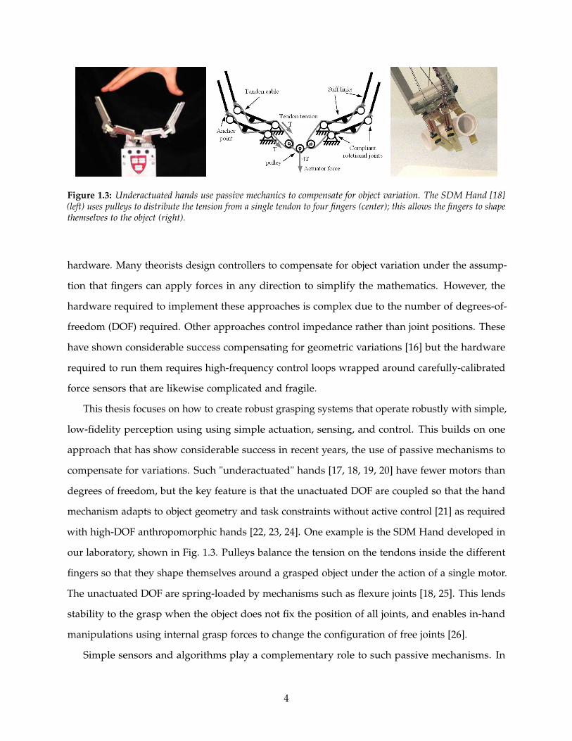
Figure 1.3: Underactuated hands use passive mechanics to compensate for object variation. The SDM Hand [18](left) uses pulleys to distribute the tension from a single tendon to four fingers (center); this allows the fingers to shapethemselves to the object (right).
hardware. Many theorists design controllers to compensate for object variation under the assump-
tion that fingers can apply forces in any direction to simplify the mathematics. However, the
hardware required to implement these approaches is complex due to the number of degrees-of-
freedom (DOF) required. Other approaches control impedance rather than joint positions. These
have shown considerable success compensating for geometric variations [16] but the hardware
required to run them requires high-frequency control loops wrapped around carefully-calibrated
force sensors that are likewise complicated and fragile.
This thesis focuses on how to create robust grasping systems that operate robustly with simple,
low-fidelity perception using using simple actuation, sensing, and control. This builds on one
approach that has show considerable success in recent years, the use of passive mechanisms to
compensate for variations. Such "underactuated" hands [17, 18, 19, 20] have fewer motors than
degrees of freedom, but the key feature is that the unactuated DOF are coupled so that the hand
mechanism adapts to object geometry and task constraints without active control [21] as required
with high-DOF anthropomorphic hands [22, 23, 24]. One example is the SDM Hand developed in
our laboratory, shown in Fig. 1.3. Pulleys balance the tension on the tendons inside the different
fingers so that they shape themselves around a grasped object under the action of a single motor.
The unactuated DOF are spring-loaded by mechanisms such as flexure joints [18, 25]. This lends
stability to the grasp when the object does not fix the position of all joints, and enables in-hand
manipulations using internal grasp forces to change the configuration of free joints [26].
Simple sensors and algorithms play a complementary role to such passive mechanisms. In
4

Chapter 2, I show simple corrective actions based on sensitive binary contact sensors can greatly
increase the ability of a passive-mechanic hand to compensate for object variations; this enables the
use of simpler object models and relaxes the requirements on the perception system by creating
a larger "basin of attraction" within which good grasps are achieved. In Chapter 3, I present a
set of joint-angle sensors designed to work with compliant hands to enable both basic kinematic
measurements and also interpret interactions with the environment; the latter application is
developed in Chapter 4, where compliant joints with joint-angle sensors are used to detect contact
and determine object geometry. In Chapter 5, I show that simple compliance alone is not sufficient
for both compensating for positioning errors on light objects and maintain grasp stability on
heavy objects; this is solved using an alternate approach based around contact-relative motion
and a highly-sensitive easily-manufactured tactile sensor. Finally, in Chapter 6, I present a unified
framework based around the idea of a "variation budget" that explains tradeoffs between different
subsystems in grasping and provides a way to design more general grasping capabilities. This is
an important step towards a more systematic, quantitative approach to designing, controlling, and
characterizing robot hands that function robustly despite the variation present in environments.
Improving robots ability to compensate for such variation automatically will result in more
capable robots that require less supervision. This will and empower those with less technical
expertise to use robotic technology such as factory workers in short-run manufacturing companies,
first responders removing rubble or searching for victims, consumers seeking to automate mun-
dane household chores, and elderly seeking to maintain their independence outside assisted-living
facilities.
5

Chapter 2
Piezo Contact Sensors and Simple
Alignment
2.1 Grasp Planning and Online Correction
Robots need models of the objects they grasp to plan grasps. This chapter explores the hypothesis
that simple contact sensors can significantly the relax the precision of the object model required
for successful grasping.
Traditional grasp planning requires a detailed model of object geometry and pose because
it is based on grasp quality metrics calculated from contact forces (magnitude and direction).
For example, force closure is a binary metric indicating whether fingers can resist an arbitrary
wrench (force and moment) applied to the object. Form closure applies the additional constraint
that finger contact includes no tangential friction load so the object must be caged by the hand.
Epsilon quality [27] extends the binary force closure metric into a scalar metric by examining
the minimum wrench required to disturb an object from a grasp relative to maximum finger
force. For an overview of these metrics, see Bicchi and Kumar’s review [28]. These performance
methods are integrated into the most popular grasping software pipelines such as GraspIt! [8]
and OpenRave [9] that use them to sample a wide variety of grasps in simulation to determine
where to place the hand.
Planning around object contact forces is sensitive to small variations in object geometry and
6

pose because they result in large changes in the direction or magnitude of grasp forces. These
have been shown to significantly affect grasp quality metrics [10]. Under perception uncertainty,
such models are challenging to obtain due to geometry errors, pose errors, and incomplete
data. Known objects in unknown poses can be efficiently localized using binary tactile contact
sensors [29, 30], but this requires an a priori object model. Unknown objects must be tediously
mapped for grasp planning in simulation, using for example the approach presented by Maekawa
in [31] , or the force magnitude and direction at each finger must be measured directly for online
control [32], which requires in-finger force-torque sensors that significantly increase system cost.
Thus, compensating for object variation by simulating or directly controlling grasp forces has
proven more useful in theory than in practice.
Several approaches have been proposed to relax the precision required of the object model.
The first is planning around geometric approximations of the model and aligning hand geometry
to these features. For example, Miller et al. presented an approach in [33] that matches grasp
primitives such as an opposing pinch to geometric primitives such as prisms segmented from
object feature approximations, and Klingbeil et al. present a grasp-site classifier based on the
shape of a parallel-jaw gripper [12]. Hsiao et al. present heuristics based on the major axis of
objects and a "lip" feature for items such as bowls [34], and Herzog presents a method to search
new objects for grasp sites that match the geometry of past successful grasp sites [13]. Another
approach is the use of compliance and underactuation [18, 17] as described in Chapter 1, which
enables the hand to adapt its shape to rough geometry models.
Sensing also plays a role. Discrete contact signals are used, for example, by Natale and
Torres-Jara [35] to perform guarded moves (although they do not characterize the impact this
control strategy has on grasp success). Continuous measurements can also be used to maintain
force below a given threshold, as in the work of Felipe and Morales [36]. Guarded moves have the
advantage of simplicity in both sensor design and control, and others have recently also taken this
approach, including Hsiao and Ciocarlie who use guarded moves to correct for local positioning
errors when performing pinch grasps on unknown objects [34], and Maldonado et al., who use a
similar method to correct for errors in positioning to achieve a robust enveloping grasp [37].
In this chapter, I present a low-cost contact sensor design integrated into a compliant hand,
and show that a simple grasp refinement algorithm based on the outer bounds of the object in
7

two dimensions reduces the precision required for a basic object model (merely the center of the
object), which results in more than doubling the effective "basin of attraction" for a successful
grasp.
2.2 Piezofilm Contact Sensor
A wide variety of sensor can be used to accomplish contact detection. A piezoelectric polymer film
element was selected (model DT1-028K/L, MSI sensors, Hampton, VA, USA, terminated with a
10MΩ load resistor) because of its high sensitivity, low cost, and excellent durability. These sensors
are molded into the compliant fingerpads of the SDM Hand introduced in Chapter 1 (Fig. 2.1).
These sensors generate an electrical charge in proportion to the applied strain, have excellent
frequency response and high sensitivity, but have no static response. The sensor responds to strain
changes in the load normal to the finger surface, so it senses the transient when the fingerpad is
deformed on initial contact as well as when contact is removed. In addition to the noncontact-
contact transition, the sensor responds to changes in load on the finger surface during grasping
and manipulation. Prior work in our laboratory characterized the sensor, demonstrating a response
of approximately 1.38 volts per Newton under a step load applied with a spherical indentor
that was rapidly removed (fall time under 10ms), and an RMS sensor noise of approximately
0.015N [38]. The reading from each sensor was converted to a signal/noise value and thresholded
to yield a binary contact value for use by the positioning algorithm used in the following grasping
study. The baseline noise value was calculated by averaging the absolute value of the sensor
reading with a first-order IIR low-pass filter with a cutoff frequency of 0.1 Hz. The sensor readings
during experiment were filtered to reduce noise with another first-order IIR lowpass filter (cutoff
frequency 500 Hz) and then divided by the baseline noise reading to generate a signal/noise value
appropriate for thresholding. Fig. 2.2 shows a series of sensor responses to a typical grasping
operation performed with the SDM Hand attached to a manipulator arm.
To mold the sensors in place, the shape deposition manufacturing (SDM) process is used [39].
In order to become commercially viable, the majority of robotic and mechatronic systems must
eventually become compatible with inexpensive, mass-manufacturing processes such as injection
molding. Fabrication processes such as multi-material molding and insert molding allow for
8

R10M
Sensor
Vcc+10V
-Vcc-10V
OP482ADC
(a) (b) (c)approximate placement
of piezofilm
piezofilm
leads
Figure 2.1: (a) Piezofilm element, (b) schematic of preamplifier circuit, and (c) approximate placement within thefingerpads of the SDM Hand embedded approximately 3mm below the surface.
some expansion of the types of systems that can be easily fabricated with modern processes, but
have not yet produced fully-integrated sensorized commercial systems with intrinsic transducers.
On the scale of small-batch fabrication of research hardware, SDM is a popular polymer-based
process, which can allow for the fabrication of compliant mechanisms that are very difficult to
fabricate with traditional techniques. Complex mechanisms with embedded components can be
created as a single part, eliminating the need for fasteners, and reducing the likelihood of damage
to fragile components by encasing them within the part structure.
Typical sensor feedback from a grasping task is shown in Fig. 2.2. The first plot shows three
distinct contact events in which a fingerpad contacts an object during object acquisition. These
events show an initial negative response at contact with a positive peak generated when the
contact is removed. The height and sharpness of the peaks are dependent on how quickly the
contact force is applied. The second plot of Fig. 2.2 shows the sensor output as the fingers of
the hand are closing around the object to secure the grasp, with the base of the hand remaining
stationary. The signal has smaller amplitude due to the slower speed at which the fingers close.
The oscillations seen in this signal are a result of vibrations induced as the remaining fingers
contact and apply force to the target object. The third plot in Fig. 2.2 shows the sensor response
as the manipulator arm moves the object while grasped by the SDM Hand. The first transient
shows the sensor response as the object is lifted off the table surface, where the changing load
forces cause stress changes within the contact sensor. The portions of the signal marked “Motion
up” and “Motion down” denote when the manipulator is moving the SDM Hand vertically up in
the air and back down again, where small vibrations due to controller action are apparent. The
9

1 3 4 5
0.8
0.6
0.4
0.2
0.0
-0.2
-0.4
-0.6
Senso
r R
esp
onse
(V
)
Contact during 'Reach'
Contact
Contact
time (sec)
Sen
sor
Resp
on
se (
V)
Time (sec)
Close hand around object
0.1
-0.2
-0.15
-0.1
-0.05
0.0
0.05
0.5 1 1.5 2 2.5 3
Lift object off table
Motion up Motion down
Replace object on table
2 4 6 8 10
Time (sec)
Sen
sor
Resp
on
se (
V)
0.2
0.1
0.0
-0.1
-0.2
-0.3
-0.4
-0.5
-0.6
Figure 2.2: Piezofilm contact sensor output for various phases of the grasping process: initial contacts during reach(upper left), increasing grasp force during object acquisition (upper right), and internal forces during object lift andmanipulation (bottom)
final transient occurs when the object comes back into contact with the table. The results of these
tests with the embedded piezofilm contact sensor show that the sensor can rapidly respond to
low force contact transients. This allows a manipulator to react quickly to minimize contact forces
with the object or environment, yet still operate at a reasonable speed.
2.3 Grasp Alignment Algorithm
Using feedback from the contact sensors, an algorithm was created that uses contact with the
target object to re-center the hand in two dimensions with respect to the target object given some
initial positioning error. Fig. 2.3 and Fig. 2.4 describe our basic “reactive control” algorithm which
utilizes sensed contact with the target object to reposition the hand such that the object is centered
in the grasp to increase stability of the grasp and balance contact forces. This algorithm is a
10

straightforward implementation of more generalized frameworks for sensor-based control of robot
hands (e.g. Tomovic et al. [40], Howe et al. [41], Hyde et al. [42], Natale and Torres-Jara [35]).
As shown in Fig. 2.3, the hand first approaches the object along the y-axis normal to the palm
until contact occurs. If this is on an inner link, it backs up to clear these links, and moves to the
side until contact occurs. The location of this contact is used to determine a line in the plane of the
workspace that represents a bound on one edge of the object. The hand is then moved along the
x-axis until contact is made on the opposing side of the hand, with the resulting contact location
used to determine a second bounding edge of the object. The manipulator then centers the hand
on the bisector of these two lines (which contains the object’s center for objects symmetric about
the y-axis), and approaches until contact occurs a third time. At this point, the manipulator stops
and attempts to grasp and lift the object, which is now more appropriately centered in the hand.
If the initial contact occurs on one of the inner segments, the manipulator is first backed up 5cm
and then follows the same procedure. This is done in order to utilize the contact sensors on the
distal finger links, which generated more reliable contact signals during motion in the x-direction
due to their wider spacing left to right. For the proximal sensors, the manipulator velocity is
still very low at contact on the opposing sensor (step five in Fig. 2.3) due to the close spacing
of the proximal finger links and the manipulator control gains. Note that abrupt contact with
the target object sometimes triggered readings from multiple sensors, so a truth table was used
as necessary to interpret whether these events are sharp collisions on one link of the hand or
indeterminate contact with a larger region of the hand (generating an ‘error’ that was processed
as an unsuccessful grasp).
2.4 Materials and Methods
To evaluate its effectiveness in unstructured environments, I measured the ability of the algorithm
to generate a successful grasp when a target object’s actual position is offset from its expected
location. The results of the reactive algorithm are compared to those of a basic “feed-forward”
algorithm, where the hand moves to the target position and immediately closes the fingers,
attempting to grasp the object and lift it out of the socket. This is the method utilized in [43].
Both algorithms are evaluated in terms of the grasp success and the magnitude of the planar force
11

(a) Initial Approach
(d)Outer Contact 1
(e)Outer Contact 2
(f)Center
(g)Approach
(h)Grasp
**
**
(b) Inner Contact
(c)Backup
x
y
hand
object
contact
inner link clearance
objectbound
objectbound centerline
contact
contact
contact
Figure 2.3: Hand adjustment algorithm: (a) The hand approaches the object until (b) contact is detected and it stops.(c) If this contact occurs on a proximal link, the hand backs up until the inner links are cleared (this step is skipped ifinitial contact is on an distal link). (d & e) The hand performs guarded moves to the left and right to determine theouter bounds of the object, (f) the hand centers on the object, and (g) the hand approaches until proximal contact, atwhich point (h) the hand closes.
advance
Innercontact
backup
clear innerphalanges
movesideways
outercontact
movesideways
outercontact
movesideways
zeroed onest. pos. advance contact grasp
travel lim.sensor err.
travel lim.sensor err.
travel lim.sensor err.
State
State Transition Trigger
error
error
error travel lim.sensor err.
error
Figure 2.4: State diagram of hand adjustment algorithm with transition triggers.
12

*
Figure 2.5: Experimental Setup: the hand is mounted on a robot arm and controlled in 3 DOF.
exerted on the object during the grasp.
The hand was mounted on a cable driven robot arm (WAM by Barret Technology, Inc, Cam-
bridge, MA) as shown in Fig. 2.5. The robot was configured to operate in a planar configuration
during the approach phase of the grasp, with the shoulder roll used to lift target objects after
grasp. Positioning commands were given in Cartesian coordinates and converted to trajectories in
joint space, with a PID loop control running at 1000 Hz on a coprocessor (DS1103 PPC, dSpace
Inc., Novi, MI). To increase performance and allow for the use of lower gains, the robot controller
uses a feedforward model of the forces on the arm (before contact with the object), including
compensation for torque ripple, gravity, and friction.
The arrival of the end-effector at a commanded position was defined as being within 1mm
of the desired position according to the forward kinematics based on the joint angle readings.
Since there is no wrist, orientation of the hand was not controlled and was determined based on
the kinematics of the manipulator at the target position. Two objects were tested with both the
feed-forward and reactive sensor control algorithm: a 48mm diameter cylindrical PVC tube and a
wood block with a cross-section of 38mm x 89mm, oriented with the wider face in the plane of the
palm of the hand (Fig. 2.5). These objects were mounted on a 6-axis force/torque sensor (Gamma
model, ATI Industrial Automation, Inc, Apex, NC, USA, 0.1 N resolution). This sensor is used to
measure the contact forces on the objects during the grasping task. Planar forces were sampled
at 1KHz; forces outside the plane of the workspace and torques were ignored, and a 20-sample
(0.02s) median filter was applied to reduce noise. Objects were mounted to the force sensor mount
13

via a square peg, such that position and orientation in the plane were fixed, yet the object could be
lifted up out of the mount after grasping. In actual unstructured grasping tasks, even small forces
can dislodge some objects, particularly if they are lightweight or top-heavy. Predicting whether
the object will move requires specification of detailed parameters such as mass distribution, three
dimensional geometry, and frictional properties at the contact with the environment and with the
fingers. This results in a large parameter space, and testing controller performance across this
range is impractical.
Fortunately, it is not necessary to directly test the entire parameter space. By measuring the
force applied by the hand to a fixed object, a prediction can be made as to whether an unfixed
object might move for a given condition. The lower the applied force, the larger the range of
objects that will not be moved, making applied force a good metric for grasping performance. For
any given object, these experimental results can be used to predict if the object would have moved
in a specific condition by comparing the force required to overcome friction and displace it with
the experimental force on the “fixed” object. Maximum force applied to the “fixed” object is then
a conservative indicator of controller quality, since some objects might be successfully grasped
even if a high enough force is applied to cause motion (e.g. if the object simply slides towards the
other finger). Combining the maximum net force measure with the assumption that the object
does not move reduces the parameter space to a tractable size but preserves the key result.
The experiment begins by finding the “zero position” for the particular object and location.
This position was taken as the point at which the hand contacts the object without any deflection,
centered on the object, representing the ideal positioning of the hand under perfect visual sensing
(hand is centered on the object) and perfect contact sensing with zero manipulator inertia (allowing
the manipulator to stop at the instant of initial contact) as in [43].
The y direction was taken as the normal vector to the palm of the hand at the zero configuration,
with x being taken in the plane of the hand, parallel to the ground as shown in Fig. 2.3. To
simulate errors in object location estimates that would occur in unstructured environments, the
robot was positioned at 10mm increments from the zero position in the positive x (symmetry in
the positive and negative x direction was assumed) and positive nd negative y directions (grasping
behavior is not symmetric in y). Forces on the object and whether the grasp was successful were
recorded for each of these positions. In doing so, we evaluate the range of positions offset from the
14
X Displacement (mm)
Y D
ispla
cem
ent
(mm
)
0 50 100
-50
0
50
Dis
pla
cem
ent
Forc
e (N
)
0
2
4
6
8
10
12
Dis
pla
cem
ent
Forc
e (N
)
X Displacement (mm)
Y D
ispla
cem
ent
(mm
)
0 50 100
-50
0
50
0
2
4
6
8
10
12
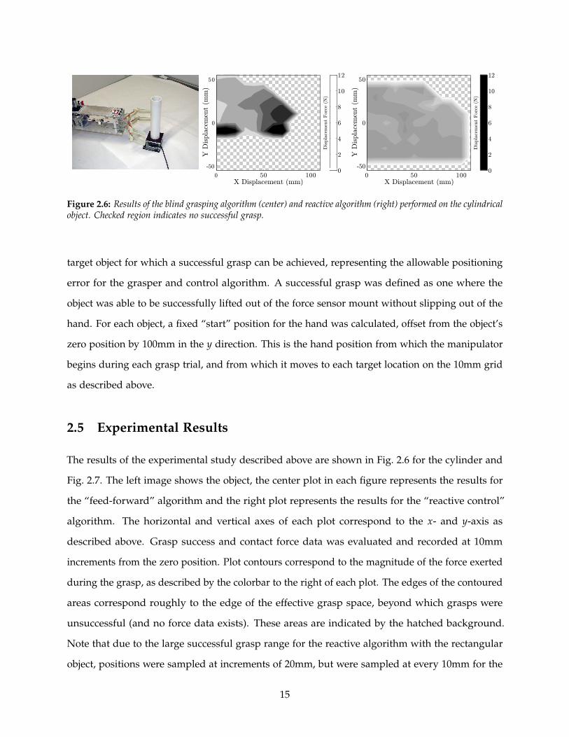
Figure 2.6: Results of the blind grasping algorithm (center) and reactive algorithm (right) performed on the cylindricalobject. Checked region indicates no successful grasp.
target object for which a successful grasp can be achieved, representing the allowable positioning
error for the grasper and control algorithm. A successful grasp was defined as one where the
object was able to be successfully lifted out of the force sensor mount without slipping out of the
hand. For each object, a fixed “start” position for the hand was calculated, offset from the object’s
zero position by 100mm in the y direction. This is the hand position from which the manipulator
begins during each grasp trial, and from which it moves to each target location on the 10mm grid
as described above.
2.5 Experimental Results
The results of the experimental study described above are shown in Fig. 2.6 for the cylinder and
Fig. 2.7. The left image shows the object, the center plot in each figure represents the results for
the “feed-forward” algorithm and the right plot represents the results for the “reactive control”
algorithm. The horizontal and vertical axes of each plot correspond to the x- and y-axis as
described above. Grasp success and contact force data was evaluated and recorded at 10mm
increments from the zero position. Plot contours correspond to the magnitude of the force exerted
during the grasp, as described by the colorbar to the right of each plot. The edges of the contoured
areas correspond roughly to the edge of the effective grasp space, beyond which grasps were
unsuccessful (and no force data exists). These areas are indicated by the hatched background.
Note that due to the large successful grasp range for the reactive algorithm with the rectangular
object, positions were sampled at increments of 20mm, but were sampled at every 10mm for the
15

Dis
pla
cem
ent
Forc
e (N
)
X Dispacement (mm)
Y D
ispla
cem
ent
(mm
)
0 50 100
-150
-50
50
0
2
4
6
8
10
12
X Displacement (mm)
Y D
ispla
cem
ent
(mm
)
-150
-50
50
0
2
4
6
8
10
12
Dis
pla
cem
ent
Forc
e (N
)
0 50 100
Figure 2.7: Results of the blind grasping algorithm (center) and reactive algorithm (right) performed on the block.Checked region indicates no successful grasp.
other three cases.
2.6 Discussion
As expected, the addition of feedback from the contact sensors on the hand significantly decreases
the forces applied to the object as it is grasped, as well as significantly increases the range of
acceptable positioning offsets that still result in a successful grasp. In particular, the grasp space
for the cylindrical object has been increased from approximately ±80mm in x and -30mm to
+50mm in y to ±120mm in x and ±50mm in y. For the rectangular object, the grasp space was
increased from approximately ±90mm in x and −30 to +40mm in y to ±120mm in x and -160mm
to +60mm in y. Put another way, the robot can cope with an initial object position estimate up to
±5cm away from its actual location in any direction (e.g. due to sensing error) for either of these
objects and still get a successful grasp, utilizing only very basic sensing and control.
Furthermore, unbalanced contact forces on the objects were limited to between 3-5 N for all
successful grasp locations for the reactive control algorithm, whereas large regions of greater than
double those values were observed under the feed forward control method. For the “feed-forward”
algorithm, the effective grasp region is bounded on the top and side (large offsets from the zero
configuration) by the tendency of the object to slip out of the grasp because it is contacted by only
the outer links of the fingers. On the bottom edge, the range is limited by the force exerted on
the object as the arm approaches and grasps (i.e. the robot tries to push the hand through the
object, dislodging it from its rest position). For the “reactive control” algorithm, the lower edge of
16

Figure 2.8: Beyond the basic success/failure criteria noted in Fig. 2.6 and Fig. 2.7, the quality of the grasp resultingfrom the reactive algorithm was often superior. Poor grasp quality (left) and good grasp quality (right).
the effective grasp space is limited by poor sensor readings at contact with the object. The grasp
space is much larger for the rectangular block due to a stronger object edge contacting the sensor.
The upper edge of the range is only limited by the reach of the manipulator arm. On the side, it is
simply limited by the width of the grasper (100mm). There is, however, regions of “successful
grasps” beyond this due to the oblique approach caused by the fixed starting position, but this
data does not add useful information since it suggests that the hand could detect objects wider
than the hand itself. Besides the performance improvements reflected in Fig. 2.6 and Fig. 2.7, the
quality of the grasp for the reactive control was visibly better over much of the space than for
feed-forward control. An example of this effect is shown in Fig. 2.8. Although the object in the
grasp does not drop and the grasp is thus judged “successful” in our classification, it has been,
perhaps unacceptably, shifted to an awkward orientation and is less robust to disturbances during
the manipulation. During the experiments it became clear that manipulator inertia dominates the
forces applied to the object during the approach phase. Contact was able to be sensed at a very
low force threshold, but by the time the manipulator was able to be stopped, the applied force
rose substantially. Control gains and approach strategy should be carefully considered in order to
minimize manipulator velocity when contact with a target object is imminent.
Several limitations are also present that form the basis for work presented in later chapters.
The first is the response of the film itself, which only measures the derivative of the force in time.
Because of this, the hand has a tendency to miss slow contacts with soft objects. This is addressed
17

in both Chapter 4 and Chapter 5. Chapter 4 presents a method to detect contact using compliant
fingers and the joint-angle sensors developed in Chapter 3. Chapter 5 presents an improved
sensor design that measures small static forces and could replace the piezeo sensor used in this
study. Another limitation is the two-dimensional nature of this study. Many objects sit upright
on vertical surfaces so such alignment is a particularly important behavior, but it may not be
sufficient for other objects (such as rubble). Finally, the hand is only tested against a limited range
of objects, using only power grasps. A framework to understand hands’ abilities to perform across
more general variation including object shape and pose is presented in Chapter 6.
2.7 Conclusions
These results demonstrate that simple tactile sensing significantly relaxes the requirements on
object model precision for grasping with compliant hands. Historically, much of the literature has
focused on finding models required to achieve the “best” grasp for a given object, rather than
determining (and relaxing) the requirements of a model that is “good enough” to plan a successful
grasp. Simple binary contact sensing does not provide a very precise estimate of the location,
but it is shown to significantly relax the precision required of simple object models (in this case,
the center of the object). Because the hand’s compliance passively adapts to the object location
and shape, the small residual errors in object location after recentering on the object generate
only small forces. These benefits from simple contact sensing would not accrue to a stiff grasper.
Small errors in object position would generate large forces unless the controller precisely adjusted
the joint configuration. This would be problematic due to the finite force sensing threshold and
the various time delays associated with sensing and control (sensor readout and processing time,
deceleration of the arm inertia, etc.). For grasping on mobile platforms [44, 45, 46], object model
estimates from imperfect sensing and imprecise knowledge of the mobile base and arm positions
often lead to large positioning errors of the robot and end-effector. The resulting grasping process
is therefore typically unreliable and/or exceedingly slow. The combination of hand compliance
with simple contact sensors as described in this chapter can enable simpler cameras, simpler
perception algorithms, and lower-cost arms.
18
Chapter 3
Joint-Angle Sensor for Flexure Joints
3.1 Introduction
Joint-angle sensors are important for determining finger kinematics and understanding interactions
with the environment. Unlike rigid systems, compliant systems move in response to loads and
interactions with the surrounding environment. This gives them robustness to unexpected
collisions, and enables them to work with their environment rather than fight against it. In the
context of walking robots, the use of compliance has enabled considerable advantages in energy
efficiency and stability [47, 48, 49], and in the context of grasping it allows simpler controllers to
compensate for object variations in size and pose [50].
Flexure joints are an important mechanism used to add compliance to robot designs. They
are low-cost, easy to fabricate, low-friction (but not zero stiffness), and robust – even to off-axis
loads. A single flexure can allow deflection around multiple axes, which provides advantages for
grasping [18], and for sensing as shown in Chapter 4. Examples of flexure-based joints in robotic
systems include the Sprawl series of legged robots [51], the SDM Hand [18], the UB Hand [52],
and Compliant Framed Modular Robots [53], among others. Many systems (including the hands
used in my research) use polymeric flexures due to their low cost and ease of fabrication. While
flexures pose many advantages over traditional revolute joints, they are not compatible with
standard approaches to measuring joint position such as potentiometers or encoders. To address
this, two problems must be overcome – a way to measure the deflection of joints that lack a fixed
center of rotation, and a way to independently measure the deflection around different axes.
19

While several sensors exist for measuring the deflection of continuum members, they are not
appropriate for polymeric flexure joints. For example, flexible steel spines have been instrumented
with strain gauges [53] to sample bending in one plane, but this approach is not suitable for
the large-scale elastic deformations observed in polymeric flexure joints. In the medical field,
Luna Innovations manufacture a sensor based on optical frequency domain reflectometry that is
able to precisely determine the shape of a flexible catheter using several bundles of optical fibers
with Fiber Bragg Gratings [54], but the electronics required to read the signals are complicated,
expensive, and bulky.
The deflection across single degree-of-freedom flexures has been measured with a variety
of different sensors such as piezoresistive bend sensors at the base of the joint [52], hall-effect
sensors across the joint [50], and optoelectric sensors across the joint [52]. Piezoresistive bend
sensors (e.g. Tactilus Flex, Sensor Products Inc., Madison, NJ) use a strip of carbon-impregnated
rubber laminated on top of an inextensible Kapton base layer to measure the bending of a long
strip. However, the kapton is not sufficiently strong to serve as the joint itself, and in pilot studies
exploring their use in flexures, I found embedding it inside rubber causes friction hysteresis since
it slips relative to the stretchable rubber joint. Existing work does not address how to extend such
measurements to multiple dimensions except for the aforementioned catheter and a preliminary
study I performed that serves as a basis for the work presented in this chapter [55].
It is therefore desirable to develop methods to measure the configuration of multi-DOF flexure
joints with simple methods that are compatible with polymeric construction. Because compliant
systems adapt to the shape of objects they interact with, it is less critical that the sensors be highly
precise, so the primary design goal for the sensor is to capture the dominant behavior of the
system with a design that is inexpensive, robust, and easy to manufacture. For use in hands,
such sensors must additionally meet the tight spatial constraints inside fingers, and must be
immune to occlusion (which excludes external cameras that are often blocked by the object or
environment during grasping). In this chapter, I first present a design based on phototransisters
and characterize its performance. Second, I present a second design
and characterize two designs for flexure-based sensors, one based on phototransistors designed
for ease of manufacture, and another based on embedded optical fibers that provides a more
complete model of joint deformation.
20

phototransistor
pair at angle
LED
Multi-DOF
Flexure Joint
3D Printed
Finger
(a)
LED
Phototransistor
Pair
Flexure
Joint
(b)
Distance
and Angle of
Incidence
(c)
Figure 3.1: (a) Joint-angle sensor in prototype finger. (b) An infrared LED shines across the joint onto two angledpairs of phototransistors. (c) As the joint bends, the changes to the angle of incidence and distance result in a voltagechange measured at each phototransitor.
3.2 Phototransistor Flexure Sensing
3.2.1 Design
The sensor consists of a single infrared LED (VLMD3100-GS08, Vishay Semiconductor) shining on
to two pairs of phototransistors (four total – OP501DA, Optek Technology), as shown in Fig. 3.1.
The two phototransistors in each pair are mounted at different angles, so that as the finger bends
around the x-axis, the LED moves between shining on one to shining on the other. As the finger
twists around the y-axis, the LED moves from one pair to the other, generating approximately 1
volt response from each phototransistor (configured as a photodarlington) over a 220-ohm pull-up
resistor. To calibrate the design, a first-order polynomial approximation is used to map sensor
readings to Euler-angle representation of orientation.
θx = c1v1 + c2v2 + c3v3 + c4v4 + c5
θy = c6v1 + c7v2 + c8v3 + c9v4 + c10
θz = c11v1 + c12v2 + c13v3 + c14v4 + c15
To fabricate the sensor, a wiring harness is created with the phototransistors and LED. This
is laid into the plastic finger, which is printed by a fused-deposition manufacturing process (3D
21

(a)
(b)
(c)
Wiring Harness
cavity
Phototransistor PairsLED
3D Printed Finger
Paused During Print
Wiring harness inserted in cavity, ready to be printed over
Joint Mold Fingerpad
Mold
Phototransistor
Pair
Figure 3.2: An embedded fused-deposition manufacturing method is used to integrate sensing into the finger design:(a) print is paused; (b) wired sensor is inserted into cavity designed to hold it; (c) whole assembly is printed over.
printer). After a cavity for the sensor is printed, the printer is paused and the harness is laid
inside as shown in Fig. 3.2. Printing then resumes, and as plastic is extruded over the sensor it
fixes it in place. This process both provides a cavity to align the sensor, and removes the need
for later assembly. The finger design includes cavities for flexure joints (16mm x 6 mm x 17mm)
and finger pads, which are then filled with two-part urethane rubber (PMC 780, Smooth-On Inc.,
Easton, PA - Shore-A durometer 80). The walls of the cavities are then peeled off, leaving the
flexure joint as shown in Fig. 3.1.
3.2.2 Experimental Evaluation
To test the response of the finger, the orientation of the distal link is measured with an electromag-
netic tracker (TrakSTAR, Ascension Technologies, Shelburne, VT) at 50Hz to an accuracy of 0.5;
voltages are measured at 10bit resolution with an Arduino Micro (Arduino, Italy) at 50 Hz, and
interpolated in MatLab (The MathWorks, Natick, MA). The finger is loaded from the tip using a
string (simulating fingertip contact) as shown in Fig. 3.3. The results are plotted in Fig. 3.3. The
respective performance of the sensor for each degree of freedom is shown in Table 3.1. Note that
the varying stiffness of the joint in different degrees of freedom results in differing magnitudes of
22

z y
x
EM Tracker
Loading Cable
EM
Transmitter
0 20 40 60
0
20
40
60
θx
Sensed
Angle
(deg)
-20 0 20-20
-10
0
10
20
θy
Angle (deg)
-10 0 10 20-10
0
10
20
θz
Figure 3.3: Experimental setup (left) and sensor response (right). The finger is clamped to the table and a cable isused to apply force to the fingertip. The resulting position of the finger is measured with an electromagnetic tracker,and sensor response is measured by a microcontroller connected to a host computer.
deflection.
Table 3.1: Phototransistor Joint Sensor Performance
Angle Range Max Error RMS Errorθx [ -4, 61 ] 5.2o 1.7o
θy [ -11, 15] 5.0o 1.3o
θz [ -2, 10] 2.0o 0.6o
The results show that the design is capable of measuring the deflection of multi-DOF flexure
joints, and demonstrate a new method to integrate sensors into polymeric devices. While the errors
are higher than seen in typical rotational encoders, there is no prior published work measuring
3-DOF polymer flexure deformations, so the results appear sufficient for this application, as
compliant fingers that adapt to the shape of object require less precise information regarding
finger placement than do stiff fingers.
3.2.3 Discussion
Embedding the sensors during the printing process provides a number of advantages. The printed
device itself serves as an alignment jig, enabling faster assembly and tighter tolerances. The
printed material also provides protection for fragile wires and the sensors themselves.
The design approaches and fabrication techniques presented here demonstrate that sophis-
23

ticated sensors can be readily incorporated into polymeric structures. A central advantage is
that the fabrication process can enable the creation of highly effective sensors by embedding
inexpensive, prepackaged transducers to create specialized sensing structures. These sensors
are part of the robot structure and are created using the same tools and forming techniques as
the mechanical structure, requiring minimal additional effort. This also permits optimization
of the overall mechanical properties of the system as well as facilitates cable routing. In the
joint-angle sensor presented above, phototransistors and LEDs are molded into a finger during a
fused-deposition manufacturing printing operation. This approach is readily extensible to other
sensors such as hall-effect sensors and allows easy alignment of the sensors to the device.
The approach also has several limitations. The primary source of error comes from the
simplistic calibration between sensor values and flexure deformation. The flexure is able to deflect
in all six degrees of freedom (translation and rotation), but only rotations are measured (the most
significant deflection modes - flexion about x, y, and z in Fig. 3.3). In practice, both the stiffness of
the joint and the geometry of the finger link play a role in the joint’s deflection under external
forces. However, the flexure is significantly stiffer in translational degrees of freedom due to the
joint and finger geometry (the flexure and distal link are roughly ten times longer than the flexure
is thick) so these other modes play a less significant role in finger behavior. To avoid overfitting,
only first-order calibration terms are used, but because rotations are non-commutative, performing
a linear fit between sensor readings and Euler-angles is only appropriate for deflections that are
comparatively small in the secondary axis. Additionally, using an optical sensor across the joint
means the design may be subject to external interference. The phototransistors selected use an
optical filter to restrict the sensed intensity to the infrared spectrum emitted by the LED, and the
addition of a bandpass filter on the signal with an actively modulated LED could further improve
interference-rejection in the linear range of the sensor. Both these limitations are addressed in the
second design based on embedded optical fibers.
24

Figure 3.4: The deformation of soft flexure joints is multimodal, and includes translation as well as rotationaldeformation.
Torq
ue(
N-m
)
0 10 20 30 400
0.05
0.1
0.15
Angle (degree s)
Stiffness Around X-Axis
−4 −2 0 2 4
-0.2
0
0.2
Angle (degree s)
Stiffness Around Z-Axis
Torq
ue(
N-m
)
0 10 20 30 40 50 600
0.1
0.2
0.3
0.4
0.5
Angle (degree s)
X-axis
Y-axis
Z-axis
Comparison
Torq
ue(
N-m
)0 10 20 30 40 50 60
0
0.1
0.2
Angle (degree s)
Stiffness Around Y-Axis
Torq
ue(
N-m
)
Figure 3.5: The joint is softest in rotation around the y-axis and in rotation around the x-axis (note: hysteresis iscaused by viscoelasticity in the joint plastic).
3.3 Optical Fiber Flexure Sensing
3.3.1 Parameterizing Joint Deflection
The deflection of flexure joints can be quite complicated, as shown in Fig. 3.4. Measuring
rotation is most important for kinematics, though measuring translation is also important because
flexures are not point pivots. Measuring this deflection is challenging, however, due to the spatial
constraints of fingers which make it difficult to install sensors to measure all 6 degrees of freedom
(DOF). Certain DOF dominate because they are softer than others as shown in Fig. 3.5, and
certain DOF receive greater loads in the context of grasping. It is therefore important to choose a
lower-dimensional parameterization of deflection that captures the dominant behavior to keep
25

costs and complexity low.
To determine which parameters to measure, a model of the joint deformation under the
expected load is required. Many different parameterizations of beam deformation have been
studied, from basic linear models that ignore shear [56] to more advanced ones such as the
Timoshenko beam equations [57]. However, most assume small deflections to allow linear
decoupling of different modes, or require computationally expensive FEM simulations that are
poorly suited to real-time sensor measurements. In both cases, they are unsuitable for fast
computation of forward kinematics in regimes where significant deflections are expected. Odhner
et al. present an excellent overview of the existing approaches and their limitations in [58]. The
key problem in any case is the difficulty of separating different modes due to the non-commutative
nature of rotation.
To address this problem, the method presented here parameterizes the deflection of the joint
with respect to the instantaneous rotation at each point along the length of the joint rather than the
total deflection of the joint itself, building on Odhner’s framework in [58]. This parameterization
makes it possible to focus on the softest deformation modes and drop stiffer ones to reduce
the dimensionality of the model. It assumes the joint is stiff in instantaneous translation (axial
compression and shear) compared to instantaneous rotation. The instantaneous rotation R(s)
can then be integrated along the length of the joint to give the total transform across the joint as
shown in Fig. 3.6. Discretizing the integral, this is
Incremental
Translation
Incremental
Rotation
dsRxRy
xi
yi
Proximal
End of Joint
Distal
End of Joint
θxd
θyd
θxp
θyp
Figure 3.6: Parameterizing joint deflection by the rotation rate along the axis of the joint. At each end, twist andflexion are measured (rotation around the third axis is ignored due to the stiffness of the joint in this direction), andlinearly interpolated in time to give a rotation rate at a series of points along the joint. These can then be integratedalong the axis of the joint to give an approximation of the total transform across the joint.
26

θxp = 30, θxd = 30
θyp = 0, θyd = 0
(a) (b) (c) (d)
θxp = 0, θxd = 0
θyp = 30, θyd = 30
θxp = 75, θxd = -75
θyp = 0, θyd = 0
θxp = 60, θxd = -120
θyp = 30, θyd = 0
Figure 3.7: The parameterization models all major deformation modes observed including (a) rotation around thex-axis, (b) rotation around the y-axis, (c) shear, and (d) coupled modes.
Rjoint =i=N
∏i=0
Ri (3.1)
where Ri is the local rate of rotation at step i along the joint, and N is the total number of steps
chosen for the discretization. In the case of wide flexures, instantaneous rotation in the plane of the
thicker axis is also comparatively stiff as shown in Fig. 3.5, leaving a two-parameter representation
of the local stiffness of the flexure Ri = RxiRyi as shown in Fig. 3.6. The displacement across the
joint can similarly be calculated by using the instantaneous orientation to calculate the direction
of each step along the length of the joint
Tjoint =i=N
∑i=0
j=i
∏j=0
Rjsi (3.2)
where Tjoint is the position displacement from base to end of the joint, si = L/N is a step along
the length of the joint L, and all other terms are as defined in the previous equation. These
parameters Rx and Ry are measured at both the proximal and distal ends of the joint (for a total
of four parameters), and interpolated along the length to give an approximation of the local rate
of rotation at a series of discrete steps along the length of the joint. This captures flex around the
x-axis, twist around the y-axis, shear, and combined modes as shown in Fig. 3.7.
3.3.2 Sensor Design
To measure local rotation around the x- and y- axis at both ends of the joint, it is necessary to
measure four parameters while meeting several design constraints. For general utility, the design
27

Optical
Fiber
Air
Bubble
Finger
Light Beam
Flexure
Motion
Pair of
Phototransistors
Flexure
Joint
Figure 3.8: Joint angle sensor design. At each corner of the joint, light from an optical fiber shines onto a pair ofphototransistors.
should be robust, inexpensive, and easy to manufacture. The entire soft joint deforms, so large
rigid components cannot be embedded in the middle of the joint. Space constraints are also
very tight, but anything protruding outside the finger runs the risk of getting caught on the
environment during grasping. Sensing across the gap of the finger joint may also suffer from
interference from e.g. external light sources.
The system shown in Fig. 3.8 was designed to meet these goals. A flexible optical fiber is
embedded in the joint so that it shines onto a pair of phototransistors. As the joint bends up and
down, it shines towards one or towards the other, measuring the local flexion. By taking the ratio
of the difference of the phototransistor signals to the sum, it is possible to cancel the effects of
variation in the light intensity (caused by manufacturing variations, interference, or wear) to the
first order.
αp1 =v1 − v2
v1 + v2, αp2 =
v3 − v4
v3 + v4(3.3)
where v1, v2, v3, and v4 are the voltages measured by the phototransistors at the proximal
end of the joint, and αp1 and αp2 are the local joint bending in the plane of the sensor at each
phototransistor pair on the proximal end of the joint. The sum of these two readings is proportional
to the local rotation around the x-axis, θx, and the difference is proportional to the local rotation
around the y-axis, θy
θxp ∝ αp1 + αp2, θyp ∝ αp1 − αp2. (3.4)
Similar equations describe the relation of the phototransistors on the distal end of the joint to the
rate of deflection at that end.
28
Fiber Aligned
by Mold Feature
MoldJoint
Mold
Optical Fiber
Molded
Alignment
Feature
Circuit BoardOptical Fiber
Phototransistors
1 2
3 4
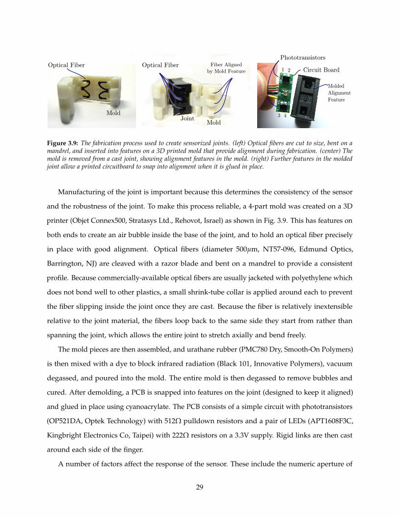
Figure 3.9: The fabrication process used to create sensorized joints. (left) Optical fibers are cut to size, bent on amandrel, and inserted into features on a 3D printed mold that provide alignment during fabrication. (center) Themold is removed from a cast joint, showing alignment features in the mold. (right) Further features in the moldedjoint allow a printed circuitboard to snap into alignment when it is glued in place.
Manufacturing of the joint is important because this determines the consistency of the sensor
and the robustness of the joint. To make this process reliable, a 4-part mold was created on a 3D
printer (Objet Connex500, Stratasys Ltd., Rehovot, Israel) as shown in Fig. 3.9. This has features on
both ends to create an air bubble inside the base of the joint, and to hold an optical fiber precisely
in place with good alignment. Optical fibers (diameter 500µm, NT57-096, Edmund Optics,
Barrington, NJ) are cleaved with a razor blade and bent on a mandrel to provide a consistent
profile. Because commercially-available optical fibers are usually jacketed with polyethylene which
does not bond well to other plastics, a small shrink-tube collar is applied around each to prevent
the fiber slipping inside the joint once they are cast. Because the fiber is relatively inextensible
relative to the joint material, the fibers loop back to the same side they start from rather than
spanning the joint, which allows the entire joint to stretch axially and bend freely.
The mold pieces are then assembled, and urathane rubber (PMC780 Dry, Smooth-On Polymers)
is then mixed with a dye to block infrared radiation (Black 101, Innovative Polymers), vacuum
degassed, and poured into the mold. The entire mold is then degassed to remove bubbles and
cured. After demolding, a PCB is snapped into features on the joint (designed to keep it aligned)
and glued in place using cyanoacrylate. The PCB consists of a simple circuit with phototransistors
(OP521DA, Optek Technology) with 512Ω pulldown resistors and a pair of LEDs (APT1608F3C,
Kingbright Electronics Co, Taipei) with 222Ω resistors on a 3.3V supply. Rigid links are then cast
around each side of the finger.
A number of factors affect the response of the sensor. These include the numeric aperture of
29
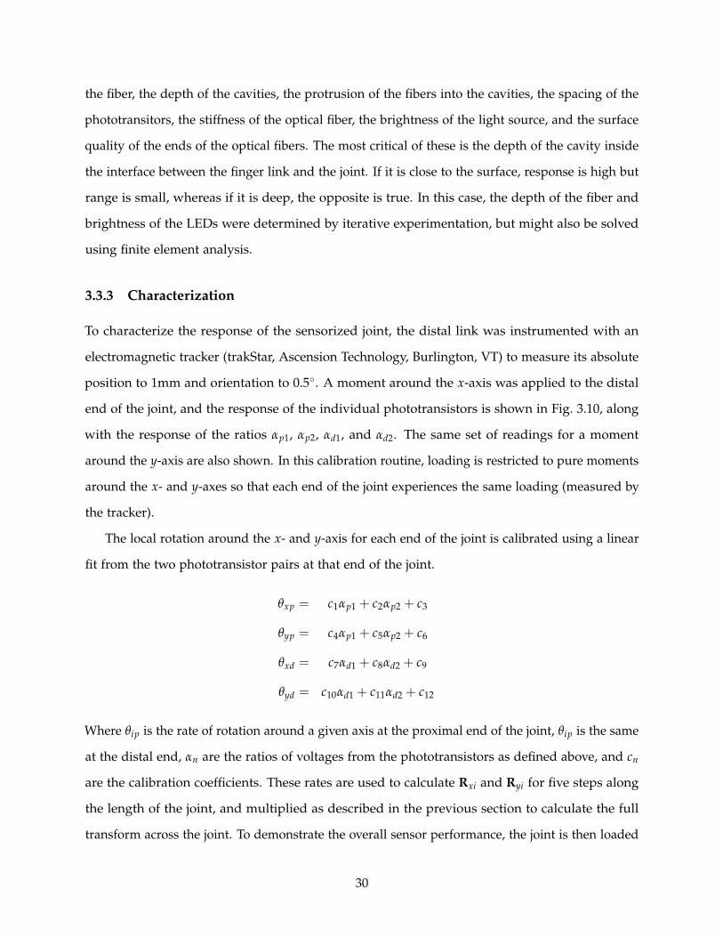
the fiber, the depth of the cavities, the protrusion of the fibers into the cavities, the spacing of the
phototransitors, the stiffness of the optical fiber, the brightness of the light source, and the surface
quality of the ends of the optical fibers. The most critical of these is the depth of the cavity inside
the interface between the finger link and the joint. If it is close to the surface, response is high but
range is small, whereas if it is deep, the opposite is true. In this case, the depth of the fiber and
brightness of the LEDs were determined by iterative experimentation, but might also be solved
using finite element analysis.
3.3.3 Characterization
To characterize the response of the sensorized joint, the distal link was instrumented with an
electromagnetic tracker (trakStar, Ascension Technology, Burlington, VT) to measure its absolute
position to 1mm and orientation to 0.5. A moment around the x-axis was applied to the distal
end of the joint, and the response of the individual phototransistors is shown in Fig. 3.10, along
with the response of the ratios αp1, αp2, αd1, and αd2. The same set of readings for a moment
around the y-axis are also shown. In this calibration routine, loading is restricted to pure moments
around the x- and y-axes so that each end of the joint experiences the same loading (measured by
the tracker).
The local rotation around the x- and y-axis for each end of the joint is calibrated using a linear
fit from the two phototransistor pairs at that end of the joint.
θxp = c1αp1 + c2αp2 + c3
θyp = c4αp1 + c5αp2 + c6
θxd = c7αd1 + c8αd2 + c9
θyd = c10αd1 + c11αd2 + c12
Where θip is the rate of rotation around a given axis at the proximal end of the joint, θip is the same
at the distal end, αn are the ratios of voltages from the phototransistors as defined above, and cn
are the calibration coefficients. These rates are used to calculate Rxi and Ryi for five steps along
the length of the joint, and multiplied as described in the previous section to calculate the full
transform across the joint. To demonstrate the overall sensor performance, the joint is then loaded
30

with moments around both the x- and y- axes, and the sensed orientation is plotted against the
ground truth from the tracker in Fig.3.11, and the results are shown in Table 3.2.
Table 3.2: Optical Fiber Joint Sensor Performance
Angle Range Max Error RMS Errorθx [ -24.7, 14.7 ] 7.0o 2.4o
θy [ -17.4, 21.8] 4.2o 1.2o
θz [ -0.7, 0.4] 0.9o 0.28o
The sensed position is plotted against the ground truth position in Fig. 3.12.
3.3.4 Discussion
These results demonstrate a simple sensor design is capable of measuring the major deformation
modes of the joint. In contrast to the design presented in Sec. 3.2, this sensor is fully enclosed and
protected from outside interference, and the improved parameterization and design allows the
measurement of larger deformations along the secondary axis of rotation (±20 vs. ±10). These
sensors were integrated into the sensing system of the i-HY Hand (Fig. 3.13).
The primary limitation of the approach comes from using using local measurements at the
ends of the compliant joint as the basis for measuring the full transform across the joint. Under
simple loading, joint deformation is distributed across the joint so the deflection at the ends serves
as a good sample point for kinematics in free space and simple contact. However, high fingertip
loads (for example during grasping) change the distribution deformation along the length of
the joint, as shown in Fig. 3.14. Since it is only sampled at the ends, these changes may not
be measured and affect sensor readings. One solution would be to combine this sensor with
measurements of tendon length or inertial measurement unit (IMU) readings. If this provides
sufficient information that the secondary deflection can be measured and modeled, this might
provide a way to measure contact force as well.
A secondary limitation is the nonlinear response of the phototransistor pairs; this limits the
precision with which deflection around different axes can be decoupled for large deformations,
and is visible in Fig. 3.11, where deflection around the y-axis has some impact on x-axis readings.
The sensitivity to loading conditions makes it difficult to use a more complicated nonlinear
31

-20 0 20
1
2
3
4
θx(degrees)
Volts
-20 0 20
0.2
0.6
1
1.4
θx(degrees)
Volts
-20 0 20
0.5
1
1.5
2
θx(degrees)
Volts
-20 0 20
0.5
1
1.5
θx(degrees)
Volts
-20 0 20
-0.5
0
0.5
θx(degrees)
(v1-
v 2)/(v
1+v2)
-20 0 20
-0.5
0
0.5
θx(degrees)
(v1-
v 2)/(v
1+v2)
-20 0 20
-0.6
-0.4
-0.2
0
0.2
0.4
θx(degrees)
(v1-
v 2)/(v
1+v2)
-20 0 20
-0.4
-0.2
0
0.2
0.4
0.6
θx(degrees)
(v1-
v 2)/(v
1+v2)
Proximal Pair 1 Proximal Pair 2 Distal Pair 1 Distal Pair 2
Rotation around X-axis
Rotation around Y-axis
αp1 αp2 αd1 αd2
-10 0 10
-0.5
0
0.5
θy
(degrees)
(v1-v
2)/
(v1+
v2)
αp1
-10 0 10
θy
(degrees)
-0.5
0
0.5
(v1 -
v2 )
/(v
1 +
v2 )
αp2
-10 0 10
θy
(degrees)
-0.5
0
0.5
(v1 -
v2 )
/(v
1 +
v2 )
αd1
-10 0 10
-0.4
-0.2
0
0.2
0.4
0.6
θy
(degrees)
(v1 -
v2 )
/(v
1 +
v2 )
αd2
-10 0 10
1
2
3
θy(degrees)
Volts
Proximal Pair 1
-10 0 10
0.2
0.4
0.6
0.8
1
1.2
θy(degrees)
Volts
Proximal Pair 2
-10 0 10
0.5
1
1.5
2
2.5
θy(degrees)
Volts
Distal Pair 1
-10 0 10
0.5
1
1.5
2
θy(degrees)
Volts
Distal Pair 2
Figure 3.10: (Row 1) Response of individual phototransistors to pure flexion around x-axis (Row 2) Ratio response αof each pair to flexion around x-axis (Row 3) Response of individual phototransistors to pure twist around y-axis(Row 4) Ratio response α of each pair to twist around y-axis.
32
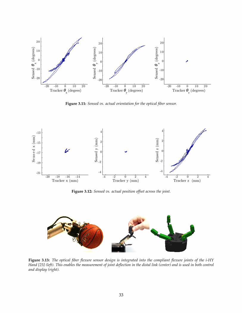
-20 -10 0 10 20
-20
-10
0
10
20
Sen
sed θx
(deg
rees
)
-20 -10 0 10 20
-20
-10
0
10
20
Sen
sed θy
(deg
rees
)
-20 -10 0 10 20
-20
-10
0
10
20
Tracker θx(degees) Tracker θ
y(degrees) Tracker θ
z(degrees)
Sen
sed θz
(deg
rees
)
Figure 3.11: Sensed vs. actual orientation for the optical fiber sensor.
-20 -18 -16 -14
-21
-19
-17
-15
-13
Tracker x (mm)
Sensed
x (
mm
)
-4 -2 0 2 4
-4
-2
0
2
4
Tracker y (mm)-4 -2 0 2 4
-4
-2
0
2
4
Tracker z (mm)
Sen
sed y
(m
m)
Sen
sed z
(m
m)
Figure 3.12: Sensed vs. actual position offset across the joint.
Figure 3.13: The optical fiber flexure sensor design is integrated into the compliant flexure joints of the i-HYHand [25] (left). This enables the measurement of joint deflection in the distal link (center) and is used in both controland display (right).
33
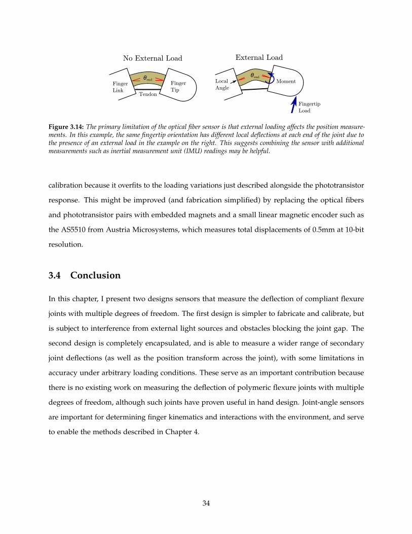
Fingertip
Load
No External Load External Load
Finger
Link
Finger
TipTendon
θendθend
MomentLocal
Angle
Figure 3.14: The primary limitation of the optical fiber sensor is that external loading affects the position measure-ments. In this example, the same fingertip orientation has different local deflections at each end of the joint due tothe presence of an external load in the example on the right. This suggests combining the sensor with additionalmeasurements such as inertial measurement unit (IMU) readings may be helpful.
calibration because it overfits to the loading variations just described alongside the phototransistor
response. This might be improved (and fabrication simplified) by replacing the optical fibers
and phototransistor pairs with embedded magnets and a small linear magnetic encoder such as
the AS5510 from Austria Microsystems, which measures total displacements of 0.5mm at 10-bit
resolution.
3.4 Conclusion
In this chapter, I present two designs sensors that measure the deflection of compliant flexure
joints with multiple degrees of freedom. The first design is simpler to fabricate and calibrate, but
is subject to interference from external light sources and obstacles blocking the joint gap. The
second design is completely encapsulated, and is able to measure a wider range of secondary
joint deflections (as well as the position transform across the joint), with some limitations in
accuracy under arbitrary loading conditions. These serve as an important contribution because
there is no existing work on measuring the deflection of polymeric flexure joints with multiple
degrees of freedom, although such joints have proven useful in hand design. Joint-angle sensors
are important for determining finger kinematics and interactions with the environment, and serve
to enable the methods described in Chapter 4.
34

Chapter 4
Contact and Object Geometry from
Compliant Joints with Angle Sensors
4.1 Background: Gentle Contact Interactions
Robots must be able to interact gently with uncertain surfaces if they are to successfully grasp
varied objects under incomplete perception and control limitations – both to survive unexpected
collisions and to explore visually-occluded regions of objects and the environment. Such explo-
ration is important for finding grasp affordances on objects such as handles and edges, for refining
grasps to match local object geometry, and for manipulating objects once they are grasped.
There is an extensive body of work on controlling contact interactions between robots and
the environment, but traditional approaches have important limitations for use in robot hands.
Stiff position control is used on most industrial arms, and although it works well for tasks such
as machining, it generates high forces in response to small position errors. This means it is not
suitable for gentle interactions such as assembling two parts or aforementioned exploration. One
alternative is controlling the force instead of the position; this works when the task constrains
the position, but results in uncontrolled behavior if the task constraint is removed (i.e. the
robot end-effector slips off the object). Another alternative is hybrid control [59], which uses
force- and position-control simultaneously in different directions; this approach is popular for
automating industrial tasks such as grinding and polishing. Another alternative is impedance
35

control [60], which controls the relationship between position and force so that the robot behaves
as a mass-spring-damper system. This more closely matches the behavior of animal muscle,
and enables safe operation in both free space and contact. More recently, Dynamic Motion
Primitives [61, 62] control the relationship between force and displacement so the system functions
as more complicated differential equations with an attractor at the goal position. This forms a
good basis for machine learning. With all these active approaches, it is expensive and complicated
to achieve gentle (low-impedance) operation due to the sensitivity required of the sensor and the
high bandwidth required of the controller.
Using passive mechanics alongside active control provides a number of advantages. In partic-
ular, passive springs comply with high-frequency transient forces due to impact, and compliant
systems do not require fast control loops to maintain stability. Series-elastic actuators [63] take
advantage of this behavior, adding a spring in series with a traditional stiff actuator and mea-
suring its displacement to estimate force. This approach has been used extensively on walking
robots [64, 65] and arms [66, 67] but has also been used on some hands [68]. One challenge with
series-elastic actuators is fitting them inside the tight packaging constraints of the hand; another
is the lack of compliance in non-actuated directions of motion.
Using compliant joints with joint-angle sensors such as those presented in Chapter 3 provides
similar passive-mechanical capabilities to series-elastic actuators without the need for separate
components. In this chapter, I present methods to detect contact and to determine object geometry
using compliant hands.
4.2 Contact Detection with Compliant Joints
Many different extrinsic sensors have been used for detecting contact, including binary switches [69],
tactile arrays [70], piezoelectric films [38], piezoelectric resonators [71], deformable fingertips filled
with fluid [72], and whiskers [73]. Other groups have used intrinsic joint-torque sensors to detect
contact [74, 75], or intrinsic force/torque sensors [76]. These have the advantage that the sensing
area can be the entire finger link surface, although they are frequently fragile. For an overview
see Bicchi and Kumar’s excellent review [28]. Although tactile sensors have been an active area
of study for over 30 years [77], systems-level questions such as sensor size, complexity, cost, and
36

Object
θ
Compliant
Joint
Fingerθ
Contact:θ > Tstatic
θ < Tacc
.. No Contact:(return path)
θ > Tstatic
θ > Tacc
..
(a) (b)
Joint Acceleration
Contact Causes Joint Deflection Finger Slips off Object
Joint Motion
Figure 4.1: Compliant joints can be used for contact detection: (a) when the finger deflects against the object surface,contact is detected via an angle threshold. (b) if the finger slips off an edge of the object, the position threshold willyield a false positive while the finger returns to rest; this can be eliminated by adding an acceleration threshold.
surface geometry have limited their successful integration into robotic hands [78].
Detecting contact with joint-angle sensors as shown in Fig. 4.1 provides several advantages
over surface contact sensors on the finger surface. Most importantly, it reduces the frequency
of missed contacts because the entire surface of the finger can transmit force to the joint in the
direction of joint compliance. It also also simplifies the control since compliant joints do not
generate high forces as a result of small positioning changes.
The forces on such a compliant finger come from three primary sources: actuation, dynamics
from the motion of the supporting hand, and contact forces with objects. The effects of actuation
force and hand motion can be controlled or modeled, leaving any remaining deformation directly
attributable to object contact. One method is to move the hand slowly with no finger actuation
and apply a threshold to the joint deflection beyond which any deflection can be attributed to
object contact. With this approach, one artifact must be corrected: the finger will “snap back” from
extended deflection, after which the angle may still be past the threshold as the finger returns
through free space. This can be corrected by using a joint acceleration threshold.
When a finger thus equipped makes contact with an object, the force F exerted on the surface
at the contact location x can be calculated from the joint stiffness K, the joint Jacobian J, and the
angular deflection vector θ. For small deformations, this comes to
JKθ = x× F
Note that the force required to detect a contact is proportional to the joint stiffness and
37

inversely proportional to the angular sensitivity of the joint-angle sensor and the radial distance
to the sensor. The most important limitation for using compliant fingers to detect contact comes
from the slow speed required to avoid inertial effects generated by hand motion. This can be
minimized by using lightweight fingers or by using a more sophisticated dynamic finger model.
4.3 Determining Object Geometry
Object geometry plays an important role in planning grasps and in characterizing and classifying
objects. Unstructured environments such as human dwellings pose a particular challenge because
they may contain unexpected obstacles, which frequently occlude machine vision systems and pose
mechanical hazards to robot hands. For unstructured environments, completeness of coverage
and mechanical robustness are key factors to avoid breaking sensors and disturbing objects. The
low-cost and high mechanical robustness of the sensors presented here match both the technical
and the economic requirements for such applications. The algorithm is also useful for tactile
mapping of the immediate environment because compliant fingers allow rapid exploration without
danger of damage.
This raw information is used to fit object models either for the local surface [79, 70, 80] or for
the object as a whole [79, 81, 69, 82]. Many such object fitting methods have been proposed, both
by the grasp planning community and by the object classification community. Ultimately it is the
application that determines which model is most appropriate–grasp planning requires accurate
surface geometry, whereas classification requires differentiating features. A useful overview of
object models is given in [83].
This section introduces a method to obtain raw tactile data using joint-angle sensors in
compliant fingers over time. Such a sensing system is well-suited to the major challenges that exist
in unstructured environments: it is mechanically robust to collision with objects and requires only
basic position-based control from the supporting arm to keep contact forces low while stroking an
object.
38

4.3.1 Object Geometry from Space Sweeping
As a finger moves through space, it carves out empty regions that do not contain the target object
as shown in Fig. 4.2. This “sculpting” analogy inspires the following approach, which generates a
discretized enveloping surface as well as contact locations. It also returns the empty space around
an object, which forms a natural basis for grasp planning in cluttered environments. Objects can
be concave or convex, but are assumed to be static and unmoving. An algorithmic framework is
presented that allows the fingers to be used for contact detection and to determine object geometry
without requiring tactile arrays or other complicated contact location sensors. This volumetric
approach to using proprioceptive sensors provides improvements in accuracy over other existing
approaches based on the intersection of planes and lines.
4.3.2 Assumptions
Assume that objects are rigid bodies that do not deform and do not move (i.e., static objects
that do not experience large forces). Likewise, assume finger links are rigid bodies. Under
these assumptions, the finger and the object cannot interpenetrate, and any space inside the
finger cannot contain the object. Assume a finger is instrumented with a sensor suite that serves
two functions: to localize the surface of the finger in space (typically using joint sensors and a
kinematic model), and to detect the existence of contact between the surface and the surrounding
environment (a boolean condition). Also assume the existence of a control system that can move
the finger through space while applying only minimal force to any object it encounters, e.g. a
finger with compliant joints on a position-controlled hand.
4.3.3 Algorithm
The Space Sweeping Algorithm starts with a region of interest in 3D space, i.e., a “target volume”
that contains the object (identified, for example, by a computer vision system).
39

Algorithm 1 Space-Sweeping Algorithm
1: Discretize a volume containing target object into a set N of voxels ni; set state of each voxelto Unexplored
2: Move finger through target volume. Update state of voxels inside finger from Unexplored toEmpty
3: When contact occurs, put all voxels containing the forward-facing surface of finger into set C.This contains all possible locations for the contact. Set state of n ∈ C to PossibleContact.
4: Narrow C by moving finger through n ∈ C and removing voxels that come inside the fingervolume, setting their state to Empty. The object prevents finger from passing through actualcontact location, but finger can pass through empty space in different orientations.
5: Stop exploring C when either:6: A.) The geometric extent of C has narrowed to an application-appropriate threshold. Set state
of n ∈ C to Contact. This results in contact location.7: B.) All appropriate motions through C have been tried. This results in a bounding surface.
Move FingerApproach
Target
Object
Finger
Finger
Surface
Contact with Object
Region of Possible
Contact Location
Contact Localization
Possible
Contact
Location
New Finger Position Shows
Contact Was Not in This Region
New
Finger
Position
Contact
Location
New Finger
Position
New Finger Position Shows
Contact Was Not in This Region
Figure 4.2: Swept-Space Elimination. When contact is detected between a finger and a static object, the currentfinger surface defines a set of potential locations for this contact. If we assume the object is rigid and unmoving, thelocation of the contact cannot lie in any region that is subsequently occupied by the finger, and finger motion narrowsthe contact location.
a.) d.)c.)b.)
Figure 4.3: Contact localization depends on object curvature and the location of the finger contact. Using the fingerpad, (a) Sharp corners can be narrowed more closely than (b) gentler curves. (c) Exploration with the finger pad canonly establish an outer bound for concave regions, but (d) fingertip exploration relaxes this limitation.
40
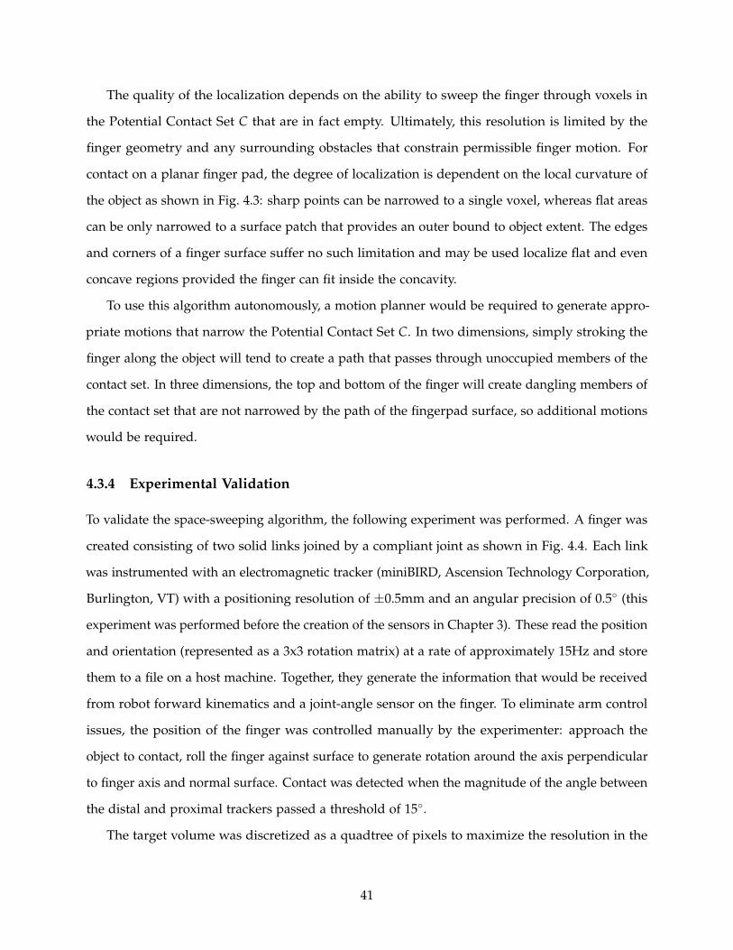
The quality of the localization depends on the ability to sweep the finger through voxels in
the Potential Contact Set C that are in fact empty. Ultimately, this resolution is limited by the
finger geometry and any surrounding obstacles that constrain permissible finger motion. For
contact on a planar finger pad, the degree of localization is dependent on the local curvature of
the object as shown in Fig. 4.3: sharp points can be narrowed to a single voxel, whereas flat areas
can be only narrowed to a surface patch that provides an outer bound to object extent. The edges
and corners of a finger surface suffer no such limitation and may be used localize flat and even
concave regions provided the finger can fit inside the concavity.
To use this algorithm autonomously, a motion planner would be required to generate appro-
priate motions that narrow the Potential Contact Set C. In two dimensions, simply stroking the
finger along the object will tend to create a path that passes through unoccupied members of the
contact set. In three dimensions, the top and bottom of the finger will create dangling members of
the contact set that are not narrowed by the path of the fingerpad surface, so additional motions
would be required.
4.3.4 Experimental Validation
To validate the space-sweeping algorithm, the following experiment was performed. A finger was
created consisting of two solid links joined by a compliant joint as shown in Fig. 4.4. Each link
was instrumented with an electromagnetic tracker (miniBIRD, Ascension Technology Corporation,
Burlington, VT) with a positioning resolution of ±0.5mm and an angular precision of 0.5 (this
experiment was performed before the creation of the sensors in Chapter 3). These read the position
and orientation (represented as a 3x3 rotation matrix) at a rate of approximately 15Hz and store
them to a file on a host machine. Together, they generate the information that would be received
from robot forward kinematics and a joint-angle sensor on the finger. To eliminate arm control
issues, the position of the finger was controlled manually by the experimenter: approach the
object to contact, roll the finger against surface to generate rotation around the axis perpendicular
to finger axis and normal surface. Contact was detected when the magnitude of the angle between
the distal and proximal trackers passed a threshold of 15.
The target volume was discretized as a quadtree of pixels to maximize the resolution in the
41

Electromagnetic
Trackers
Distal
Link
Base Link
Finger
Surface
Compliant
Joint
Figure 4.4: Experimental setup. The finger consists of two links joined by a compliant joint and fitted withelectromagnetic trackers that are used to determine the location of the finger surface and determine the angle across thecompliant joint. The base link is moved by hand, and contact is detected with a basic threshold on the magnitude ofthe joint deflection.
regions of interest (at the surface of the object) and avoid wasting memory on empty space (in
3D an octree would serve a similar function) [84]. In this space discretization, the entire region is
initialized as a single square pixel. Then, any pixel containing the finger surface is divided into
four subpixels, and the process is repeated on any subpixels still containing the finger surface until
a lower bound is reached. This bound was chosen to be 1x1mm in accordance with the resolution
of the tracker. Contact sets were thresholded at a span of 40mm to be classified as contact locations,
though in many cases (e.g. edges) the algorithm was able to localize contact to a single node as
shown in Fig. 4.5. The algorithm was implemented in Matlab (R2010a-x86, the Mathworks, Natick,
MA) and run on a personal computer, and the data structure used approximately 3000 nodes in
each experiment.
The object was placed on a table in a calibrated coordinate frame, and the finger was stroked
across its surface. Results are shown in Fig. 4.5. The algorithm was effective at determining object
geometry, especially in regions of high curvature which are important for object recognition and
classification. The error was measured by calculating the minimum difference between the actual
object location and the center of the contact node, minus half the voxel width. For the block, this
was 0.9 mm; for the cylinder it was 0.5 mm.
42

−20 0 20 40 60 80 100−20
0
20
40
60
X (mm)
Y(mm)
1mm
14mm
27mm
> 40mm
Unexplored Empty Contact
−20 0 20 40 60 80 100−20
0
20
40
60
X (mm)
Y(mm)
1mm
14mm
27mm
> 40mm
Unexplored Empty Contact
Figure 4.5: Experimental results for the Space-Sweeping algorithm used in two dimensions to trace a rectangle and acircle. The extent of the contact set is shown by the colorbar on the right–note that tracing with the fingertip wouldimprove the localization on the straight edges of the rectangle. The maximum distance between the object edge and theedge of the contact node region was 0.9mm for the rectangle and 0.5mm and for the circle.
4.3.5 Discussion
These experiments show it is possible to determine object geometry using only compliant joints
and joint-angle sensors over time, a sensor suite that is simple, mechanically robust, and requires
only basic position control in the supporting hand. The Space-Sweeping algorithm developed
here works under only the light assumption that the object does not deform or move.
An understanding of the advantages of the algorithms presented here requires detailed
comparison with the extensive prior work on the problem of determining object geometry
by proprioceptive sensors inside the fingers (the use of extrinsic sensors is discussed more
exhaustively in Chapter 5, but the principle limitation to that approach is the coverage of the
sensors on the finger surface). One related approach is whiskers, which use a passive compliant
feeler to determine object geometry. Three primary approaches have been used to determine the
location of the contact along the feeler. One is to measure the ratio of torque change to angular
velocity τ/θ which can be used to determine the distance to a contact location along a compliant
beam [85, 86, 87, 88, 89]. This closely parallels the function of rat whiskers (vibrissae) [88]. Lateral
slip of the whisker along the surface of the object can bias readings and correcting it requires
repeated measurements in multiple directions [85]. Implementing such an approach using a finger
that is neither straight nor continuously flexible is not straightforward, so a secondary set of
whiskers would be needed alongside fingers in grasping applications. Other approaches have
used the changes in resonant frequency that result when a mechanically excited whisker touches
an object [90]. Using such an approach for grasping would also requires a separate set of whiskers
43

due to the difference between continuous whiskers and robotic fingers that have only discrete
compliant subsections joining rigid links. Finally, several groups have calculated contact location
using the intersection point between whisker geometry at two different locations against an object,
using rigid [91] or flexible members [92]. However, this approach suffers from a fundamental
geometric limitation: as two lines become closer to parallel, the location of their intersection
becomes increasingly sensitive to noise in the sensor. This makes the approach unsuitable for
large gently curved surfaces, unlike the approach described in this paper.
Enveloping Grasps have been used for object classification since the early days of tactile sensing.
Briot describes a Baysian classification approach in 1972 [93], and many others have used this
sensing approach since then [79, 94]. Although this approach also uses joint-angle sensors, it has
two primary downsides: first, it does not capture concave features, which places limits on the
object models that can be used and the level of detail that can be expected. Second, executing
an initial grasp requires sufficient prior knowledge of the object position and an unobstructed
approach path to avoid collisions. This can be especially problematic in occluded environments
where tactile sensing provides the greatest advantage over other sensing systems.
Self-Posture Changability (SPC) is another sensing approach to determine object geometry with
joint-angle sensors that was developed by Kaneko and Tanie [74]. In SPC, the finger is moved
incrementally over the surface of the object under mixed position control and active compliance so
that the object surface causes a change in the position of the finger surface. Two finger positions
can then be intersected to estimate the contact location.
In contrast to SPC, the Space-Sweeping algorithm uses the finger surface itself as the mea-
surement of the object surface, rather than the intersection of finger surfaces. The two algorithms
provide a similar ability to localize the object in regions of high curvature (e.g. edges), but
space-sweeping is less sensitive to noise in regions of shallow curvature because it does not rely
on geometric intersection of tangent lines which are nearly parallel in these regions.
Joint-angle sensors are also used in Huber and Grupen’s work [75]. They use a Kalman filter to
find the location of a hypothetical contact location on a multi-joint finger based on SPC posture
intersections, the center of rotation of finger links, and the local surface velocity. The existence of
contact is then validated using torque sensors to detect which link contacts are consistent. This
enables the detection of fingertip contacts. Although they only develop the planar case, they note
44

Object
Geometry
Trace
Object
Finger
θ
Compliance
and Joint-Angles
Compliant
Joint
Joint-Angle
Sensor
Surface Normal
and Local Velocity
Surface
Normal
Local
Velocity
N⟂V - Locus of
Potential Contact
V N
Joint Moment and
Friction Cone
N
Friction
Cone
Joint
Moment
FN·F <1/μ
Figure 4.6: Compliant finger joints can also complement the approach presented by Huber and Grupen[75], obviatingthe need for impedance control and torque sensors. Contact is detected through joint deflection, and two criteria areused to narrow the location: at the contact, there can be no local surface velocity in the direction of the surface normalN(x) ·V(x) = 0, and a single contact does not exert forces outside the friction cone F · n ≤ 1
µ .
it is possible to extend to three dimensions under the assumption of a single contact. A similar
approach could be taken to use compliant joints and angle sensors to perform tip tracing, as
shown in Fig. 4.6. Passive compliance would remove the need for impedance control to guide the
finger along the surface of the object, and detecting contact by joint deflection would remove the
need for torque sensors.
Compliant Joints and joint-angle sensors have also been used determine object geometry in
earlier work from our group. Deckers, Dollar, and Howe present a conceptual framework casting
contact localization on compliant fingers as a Markov decision process [95]. I presented an initial
geometric framework for using compliant joints and joint-angle sensors to determine contact
geometry including fingertip tracing and contact localization, though only early experimental
results are presented [55]. More recently, Koonjul, Zeglin, and Pollard present three different
approaches to localize contact points to one of 10 regions on the finger of a Shadow Hand: one
based on torque equilibrium at the joints, an implementation of SPC using compliant fingers, and
an empirical approach based on a classifier and training data [96].
For the Space-Sweeping algorithm, the most important limitation comes from the assumption
the object does not move. This limits its suitability for use during manipulation when the object
moves in a hand, though it may still work if the object is held fixed and stroked by a free finger.
This premise also limits its use for very light or very compliant objects due to the stiffness of the
joints and friction in the tendon sheaths. Both this algorithm and the contact detection method
presented in Section 4.2 might benefit from the addition of a small saturating series-elastic element
45

at the base of the finger.
The resolution is limited by the node size. This discretization error sets a lower bound on the
precision that can be generated, but it is isotropic and only causes a quantitative error (that scales
with the node size), as opposed to the singularity created by line intersection approaches which
may cause qualitative changes in the detected object geometry. More importantly, graspers can
handle some amount of surface error–in some cases up to several centimeters [97]–and below
a certain scale, other parts of the system such as a robot arm controller become the dominant
cause of error. Finally, the volume discretization requires more memory than a basic contact-point
representation. However, this is decreasingly important as the price of memory continues to drop.
To reduce the memory needed, the discretization could also be applied locally on the scale of the
finger and then converted to a more compact form once the surface has been determined.
4.4 Conclusion
In this chapter, I demonstrate methods to use joint-angle sensors on compliant joints to detect
contact and to determine object geometry without the need for high-fidelity force control or joint-
torque sensors. This provides a new way to explore unknown objects under strong perceptual
and robot control uncertainty because the passive mechanics of the compliant fingers perform
the local control required to maintain contact. Such information is important for identifying the
outer bounds of objects for grasping, locating grasp affordances on objects such as edges between
an object and the surrounding environment, and for detecting unexpected collisions with the
environment.
Two principle advantages to using proprioceptive sensors for this purpose are their widespread
integration into hands (joint-angle sensors are present on most robots) and and their wide field of
sensitivity – unlike external tactile arrays, the entire finger surface functions as the contact surface
in all directions that a link is compliant. This can be combined with extrinsic sensors to provide
both high sensitivity and limited deadzones, as used in Chapter 6.
46

Chapter 5
MEMS Barometer Tactile Sensors and
Contact-Relative Control
5.1 Compensating for Alignment Errors
In this chapter I examine the limitations of compliance as a means to enable effective grasping of
the diverse objects encountered in unstructured environments and present a tactile sensor that is
shown to improve these limitations. Underactuated hands compensate for variations in object
shape and pose using the deflection of passive mechanisms, as discussed in Chapter 1. During
grasping, the deflection of these compliant joints is determined by the contact constraints, actuator
motions, and joint stiffness. In many underactuated hands, the unactuated DOF are constrained by
compliance such as that imparted by flexure joints [98, 25]. Designs of such hands have been based
on intuition, kinematic optimization [99, 100], and task analysis [25]. There has, however, been a
limited understanding of the role of compliance in real grasping tasks using multifingered hands,
including its relationship to object and task properties. Such an understanding will improve hand
design and enable the creation of more effective grasping controllers.
In general, when any coupled joints are not constrained by the geometry of the grasped object
(for example, during fingertip grasps), compliance must be set to accommodate the heaviest
objects (or highest forces) that will be encountered in order to maintain stable control of the
position of the object. This means that for lighter objects, the benefits of compliance (i.e. low
47

Figure 5.1: Compliant underactuation allows hands to passively adapt to alignment errors from robot and perceptionlimitations and adapt to object geometry – the more compliant the hand, the better the adaptation (a). However,unconstrained compliant joints can deflect under grasp forces and eject the object – the stiffer the hand, the firmer thegrasp (b) These competing requirements limit the dynamic range of objects that can be grasped. Registering controlactions against the object surface with tactile contact sensing resolves this limitation using simple hardware (c).
forces in response to sensing and control errors) are obviated, and target objects may be dislodged
or damaged in the grasp acquisition process, as shown in Fig. 5.1.
In the following sections (research performed in collaboration with Yaroslav Tenzer and Qian
Wan), I present an analysis of the limits of fingertip compliance to both maintain firm grasps and
gently compensate for positioning errors, followed by a design for sensitve tactile sensors based
on MEMS barometers. This enables a method based around simple contact sensing that uses
the point of contact with objects as a reference point for subsequent compliant motion. This is
compatible with low-cost, simple hardware and results in better compensation for positioning
errors. Experiments are presented that demonstrate the advantages of contact-relative motion to
improve the tolerated positioning error and reduce grasp force. Finally, these results are analyzed
in the context of creating low-cost hands that function reliably in real-world settings.
5.2 Limits to Compliance
The limitations on the useful range of compliance can be illustrated with a simplified model of the
grasping process that shows the factors which determine performance for both the heaviest and
lightest objects to be grasped. Figure 5.2 shows the hand idealized as a pair of fingers grasping
heavy and light objects, with equivalent lateral finger tip stiffness k. For the heaviest anticipated
object, with mass mmax, finger stiffness must be set high enough to limit unintended motion of
the fingers and object during manipulation. One force that will be encountered in many tasks is
48

Hand
Light
Object
Fingertip
Stiffness
K
ΔXSensing
Error
ΔXObject
Droop
Hand
Heavy
Object
Figure 5.2: Compliant underactuation allows a hand to compensate for positioning errors while exerting low forces.However, compliance is also responsible for maintaining the stability of heavier objects. This limits the range of objectsthat can be grasped.
gravity, so the object weight mmaxg can be applied in various directions during translation and
rotation of the hand. The resulting displacement of the object within the hand is then
∆xmax =mmax g
2k(5.1)
In the design process, the stiffness could be set using this relationship based on the maximum
displacement that can be tolerated for the heaviest anticipated object.
For the lightest object with mass mmin, the performance limit for the grasping task occurs if
one finger makes contact with the object before the other. Continued closing of the finger then
compresses the finger tip spring and applies an unbalanced force on the object. This can make
the object slide out of the graspable range or cause it to fall. If the distance between the opposite
side of the object and the other finger is ∆xmin, then the force developed before the second finger
makes contact and applies a stabilizing force is k∆xmin. Using a simple Coulomb friction model
with coefficient of friction µ, this will cause sliding if the applied force is
µ mmin g = k ∆xmin (5.2)
We can calculate a mass dynamic range by looking at the ratio of the masses for these limiting
cases:
49
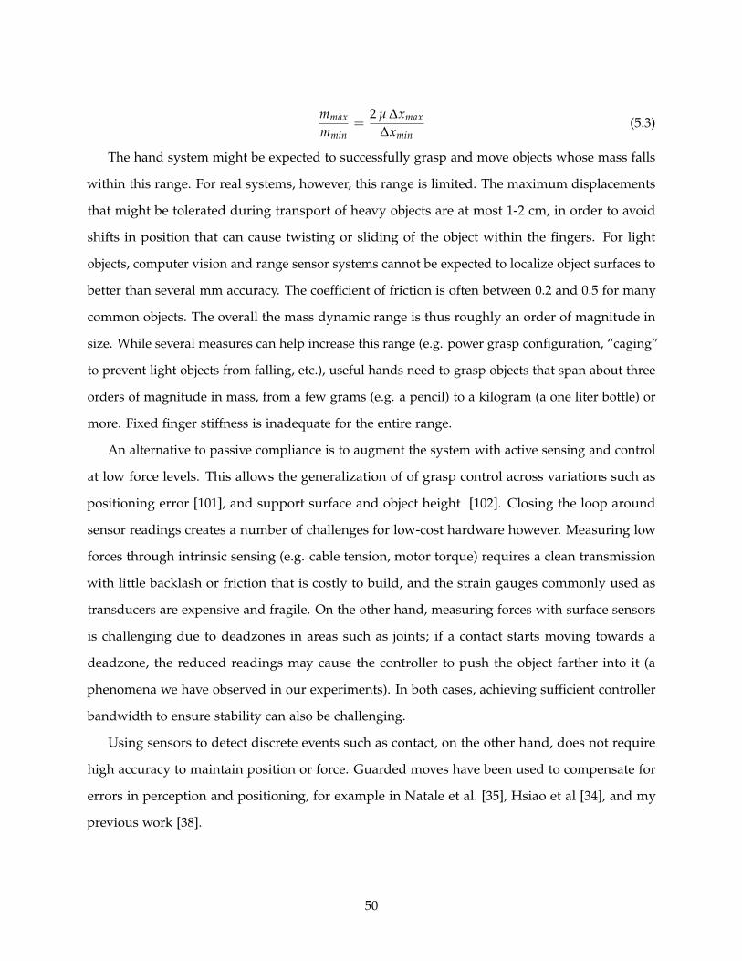
mmax
mmin=
2 µ ∆xmax
∆xmin(5.3)
The hand system might be expected to successfully grasp and move objects whose mass falls
within this range. For real systems, however, this range is limited. The maximum displacements
that might be tolerated during transport of heavy objects are at most 1-2 cm, in order to avoid
shifts in position that can cause twisting or sliding of the object within the fingers. For light
objects, computer vision and range sensor systems cannot be expected to localize object surfaces to
better than several mm accuracy. The coefficient of friction is often between 0.2 and 0.5 for many
common objects. The overall the mass dynamic range is thus roughly an order of magnitude in
size. While several measures can help increase this range (e.g. power grasp configuration, “caging”
to prevent light objects from falling, etc.), useful hands need to grasp objects that span about three
orders of magnitude in mass, from a few grams (e.g. a pencil) to a kilogram (a one liter bottle) or
more. Fixed finger stiffness is inadequate for the entire range.
An alternative to passive compliance is to augment the system with active sensing and control
at low force levels. This allows the generalization of of grasp control across variations such as
positioning error [101], and support surface and object height [102]. Closing the loop around
sensor readings creates a number of challenges for low-cost hardware however. Measuring low
forces through intrinsic sensing (e.g. cable tension, motor torque) requires a clean transmission
with little backlash or friction that is costly to build, and the strain gauges commonly used as
transducers are expensive and fragile. On the other hand, measuring forces with surface sensors
is challenging due to deadzones in areas such as joints; if a contact starts moving towards a
deadzone, the reduced readings may cause the controller to push the object farther into it (a
phenomena we have observed in our experiments). In both cases, achieving sufficient controller
bandwidth to ensure stability can also be challenging.
Using sensors to detect discrete events such as contact, on the other hand, does not require
high accuracy to maintain position or force. Guarded moves have been used to compensate for
errors in perception and positioning, for example in Natale et al. [35], Hsiao et al [34], and my
previous work [38].
50

TempSensor
DiffAmp
PressureSensor
ADC I2CInterfaceM
UX
Figure 5.3: MEMS barometers are sold in high volumes for use in cell phone and GPS systems, where they are usedto measure altitude. Due to the sales volume, they are available at very low cost despite high performance, and theyare easy to integrate with commercial manufacturing techniques.
5.3 Tactile Sensors from MEMS Barometers
Hundreds of tactile sensors have been designed using nearly every conceivable transducer
technology. For good reviews of tactile sensors, see Howe 1993 [103], Lee 1999 [104], Bicchi and
Kumar 2000 [28], and Dahiya 2007 [78]. Despite decades of research and the availability of several
commercial models, tactile sensors have yet to see widespread integration into hand designs
and control. As a result, systems level considerations such as integration/installation [105], cost,
mechanical robustness, scalability, and communication interface are now considered an important
frontier [78].
The tactile sensors used in this chapter and in Chapter 6 leverage recent developments in
consumer MEMS technology to solve these key systems-level problems. This results in sensors that
are highly sensitive, low-cost, and easy to integrate into standardized manufacturing processes.
This work was performed in in collaboration with Yaroslav Tenzer [106].
The approach takes advantage of recently-available miniature barometric sensor chips. These
have been developed for consumer products such as desktop weather stations and GPS systems,
where altimeters can improve vertical positioning accuracy [107]. As a result, these sensors have a
small footprint, low power consumption, and are mass produced at low cost. Several versions are
available, all sharing the combination of a MEMS transducer with integrated signal conditioning
and bus interface in a standard surface mount IC package (e.g.[108, 109]). The devices can be
mounted on rigid or flexible printed circuit boards using standard reflow soldering techniques
51
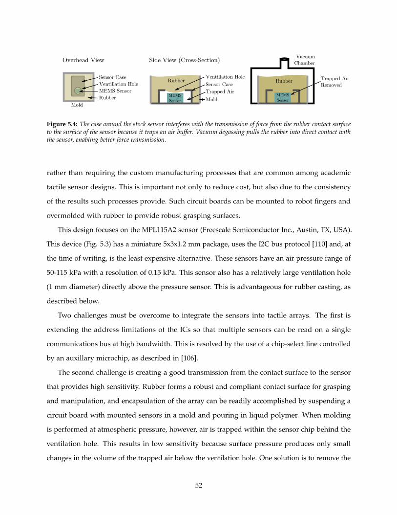
Side View (Cross-Section)
Sensor Case
Ventillation Hole
Overhead View
MEMS Sensor
Trapped Air
Removed
Vacuum
Chamber
Sensor Case
MEMS
Sensor Mold
Trapped Air
Ventillation Hole
Mold
Rubber
Rubber
MEMS
Sensor
Rubber
Figure 5.4: The case around the stock sensor interferes with the transmission of force from the rubber contact surfaceto the surface of the sensor because it traps an air buffer. Vacuum degassing pulls the rubber into direct contact withthe sensor, enabling better force transmission.
rather than requiring the custom manufacturing processes that are common among academic
tactile sensor designs. This is important not only to reduce cost, but also due to the consistency
of the results such processes provide. Such circuit boards can be mounted to robot fingers and
overmolded with rubber to provide robust grasping surfaces.
This design focuses on the MPL115A2 sensor (Freescale Semiconductor Inc., Austin, TX, USA).
This device (Fig. 5.3) has a miniature 5x3x1.2 mm package, uses the I2C bus protocol [110] and, at
the time of writing, is the least expensive alternative. These sensors have an air pressure range of
50-115 kPa with a resolution of 0.15 kPa. This sensor also has a relatively large ventilation hole
(1 mm diameter) directly above the pressure sensor. This is advantageous for rubber casting, as
described below.
Two challenges must be overcome to integrate the sensors into tactile arrays. The first is
extending the address limitations of the ICs so that multiple sensors can be read on a single
communications bus at high bandwidth. This is resolved by the use of a chip-select line controlled
by an auxillary microchip, as described in [106].
The second challenge is creating a good transmission from the contact surface to the sensor
that provides high sensitivity. Rubber forms a robust and compliant contact surface for grasping
and manipulation, and encapsulation of the array can be readily accomplished by suspending a
circuit board with mounted sensors in a mold and pouring in liquid polymer. When molding
is performed at atmospheric pressure, however, air is trapped within the sensor chip behind the
ventilation hole. This results in low sensitivity because surface pressure produces only small
changes in the volume of the trapped air below the ventilation hole. One solution is to remove the
52

top of the sensor metal case, so the rubber directly encapsulates the MEMS pressure transducer.
This improves sensitivity but requires nonstandard chip handling techniques. This exposes fragile
components such as bond wires that can break when large forces are applied to the rubber surface.
A more successful approach is vacuum degassing, as shown in Fig. 5.4. The mold is placed in
a vacuum chamber (e.g. standard laboratory bell jar) immediately after the rubber is poured,
and the air is removed with a vacuum pump. This removes the air from inside the sensors, thus
allowing the rubber to enter the case though the ventilation hole. Destructive analysis after casting
performed on a number of sensors showed that the rubber fills the sensor without damaging
internal structures.
The resulting tactile array sensors have moderate spatial resolution (3-5 mm), and excellent
sensitivity (<0.01 N), linearity (<1%), and bandwidth (>100 Hz); a full performance characterization
is provided in [106].
These sensors solve several of the primary problems that have been limiting wider adoption of
the sensors into hands. First, they provide high sensitivity in a package that is easy to manufacture
consistently with standard techniques, even at low manufacturing volumes suitable for research.
Because communication occurs over a digital bus, only four wires are required to access the array,
and they do not require special shielding to prevent crosstalk. After the sensors have been cast
under a thin layer of rubber and degassed, they can be overmolded into finger surfaces. This not
require a custom sensor shape to integrate into different finger designs because only the rubber
overmold must be matched to the finger geometry. Several examples of sensors based around this
design are shown in Fig. 5.5.
5.4 Experiments
5.4.1 Materials and Methods
It is challenging to characterize performance in unstructured environments, because they inher-
ently include great variability in objects, tasks, and environment properties. Our laboratory has
devoted extensive experimental effort to examining the grasping behavior of one such end effector,
the i-HY Hand [25]. This is a compliant, underactuated hand with three fingers developed in
collaboration between Harvard University, iRobot, and Yale University with the goal of performing
53
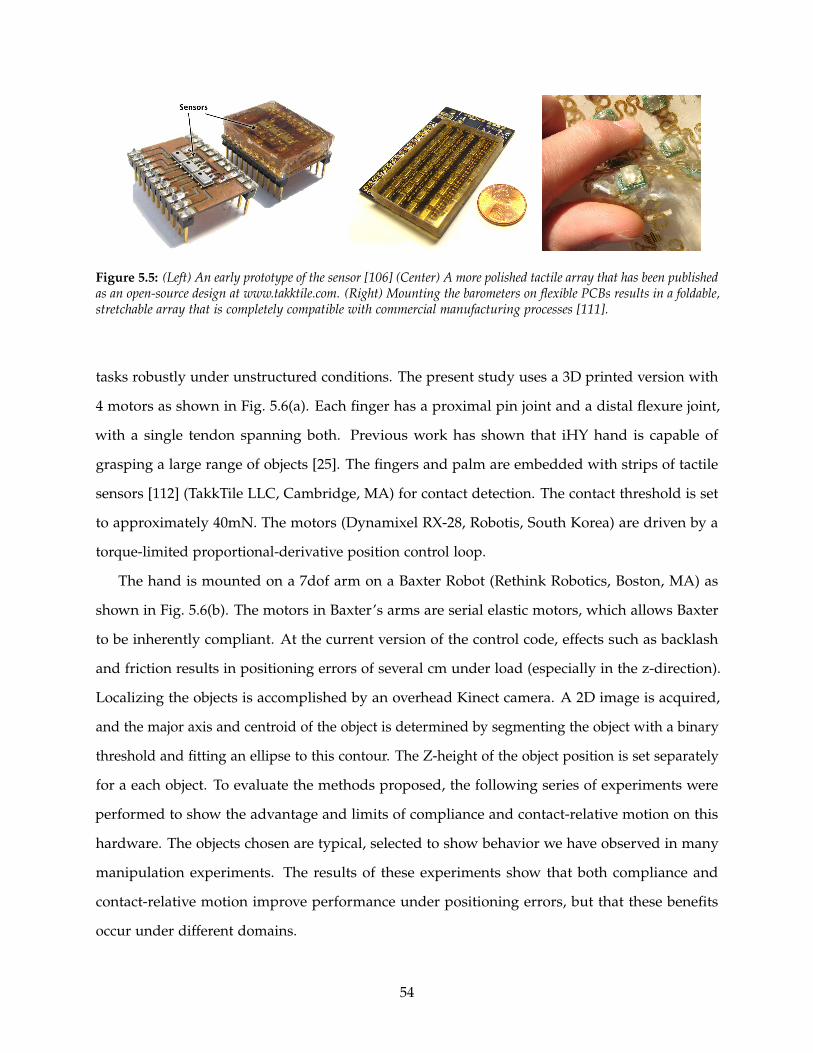
Figure 5.5: (Left) An early prototype of the sensor [106] (Center) A more polished tactile array that has been publishedas an open-source design at www.takktile.com. (Right) Mounting the barometers on flexible PCBs results in a foldable,stretchable array that is completely compatible with commercial manufacturing processes [111].
tasks robustly under unstructured conditions. The present study uses a 3D printed version with
4 motors as shown in Fig. 5.6(a). Each finger has a proximal pin joint and a distal flexure joint,
with a single tendon spanning both. Previous work has shown that iHY hand is capable of
grasping a large range of objects [25]. The fingers and palm are embedded with strips of tactile
sensors [112] (TakkTile LLC, Cambridge, MA) for contact detection. The contact threshold is set
to approximately 40mN. The motors (Dynamixel RX-28, Robotis, South Korea) are driven by a
torque-limited proportional-derivative position control loop.
The hand is mounted on a 7dof arm on a Baxter Robot (Rethink Robotics, Boston, MA) as
shown in Fig. 5.6(b). The motors in Baxter’s arms are serial elastic motors, which allows Baxter
to be inherently compliant. At the current version of the control code, effects such as backlash
and friction results in positioning errors of several cm under load (especially in the z-direction).
Localizing the objects is accomplished by an overhead Kinect camera. A 2D image is acquired,
and the major axis and centroid of the object is determined by segmenting the object with a binary
threshold and fitting an ellipse to this contour. The Z-height of the object position is set separately
for a each object. To evaluate the methods proposed, the following series of experiments were
performed to show the advantage and limits of compliance and contact-relative motion on this
hardware. The objects chosen are typical, selected to show behavior we have observed in many
manipulation experiments. The results of these experiments show that both compliance and
contact-relative motion improve performance under positioning errors, but that these benefits
occur under different domains.
54
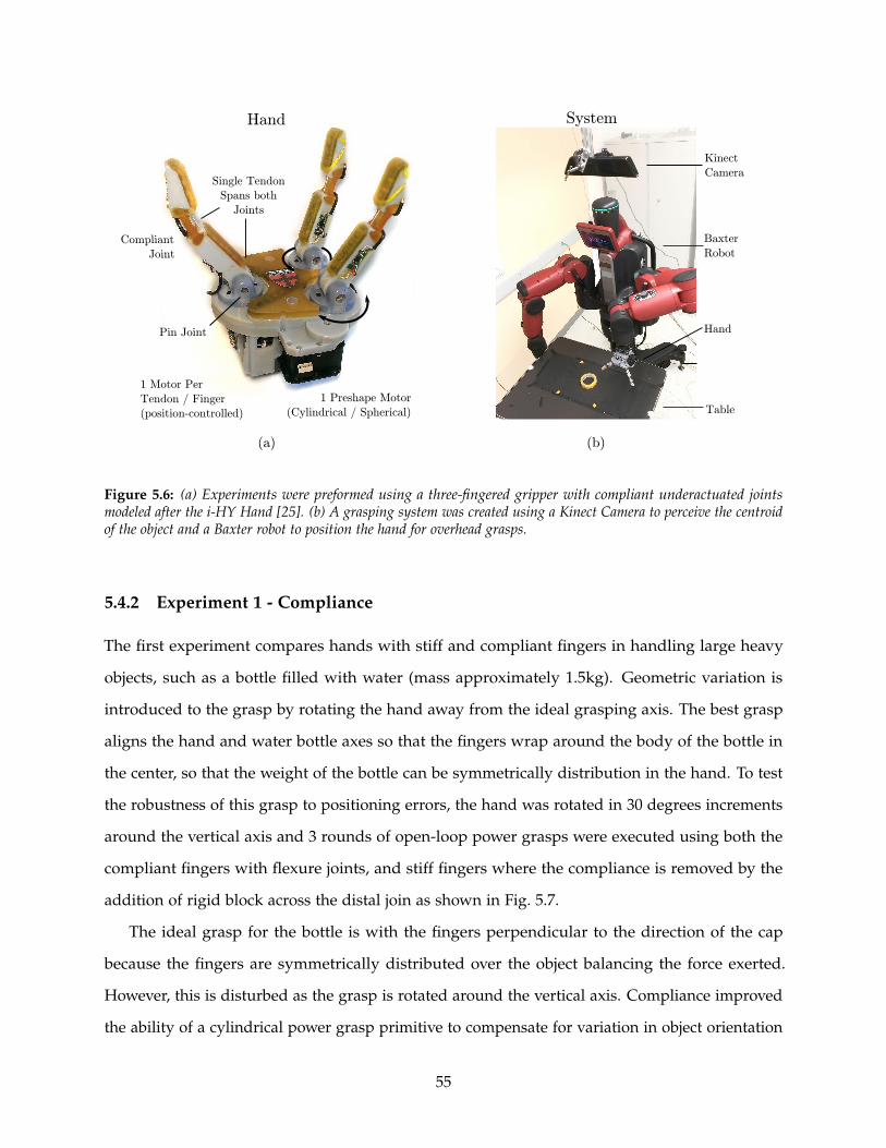
1 Preshape Motor
(Cylindrical / Spherical)
Pin Joint
Compliant
Joint
1 Motor Per
Tendon / Finger
(position-controlled)
Single Tendon
Spans both
Joints
Hand System
Table
Kinect
Camera
Baxter
Robot
Hand
(b)(a)
Figure 5.6: (a) Experiments were preformed using a three-fingered gripper with compliant underactuated jointsmodeled after the i-HY Hand [25]. (b) A grasping system was created using a Kinect Camera to perceive the centroidof the object and a Baxter robot to position the hand for overhead grasps.
5.4.2 Experiment 1 - Compliance
The first experiment compares hands with stiff and compliant fingers in handling large heavy
objects, such as a bottle filled with water (mass approximately 1.5kg). Geometric variation is
introduced to the grasp by rotating the hand away from the ideal grasping axis. The best grasp
aligns the hand and water bottle axes so that the fingers wrap around the body of the bottle in
the center, so that the weight of the bottle can be symmetrically distribution in the hand. To test
the robustness of this grasp to positioning errors, the hand was rotated in 30 degrees increments
around the vertical axis and 3 rounds of open-loop power grasps were executed using both the
compliant fingers with flexure joints, and stiff fingers where the compliance is removed by the
addition of rigid block across the distal join as shown in Fig. 5.7.
The ideal grasp for the bottle is with the fingers perpendicular to the direction of the cap
because the fingers are symmetrically distributed over the object balancing the force exerted.
However, this is disturbed as the grasp is rotated around the vertical axis. Compliance improved
the ability of a cylindrical power grasp primitive to compensate for variation in object orientation
55
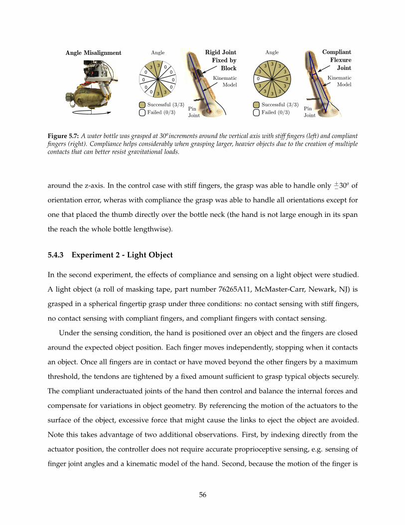
Pin
Joint
Kinematic
Model
Rigid Joint
Fixed by
Block
Pin
Joint
Compliant
Flexure
Joint
Kinematic
Model
33
33 00
0
00
0
0
0
Successful (3/3)
Failed (0/3)
Angle
33
0
33 3 3
3
3
33
Successful (3/3)
Failed (0/3)
AngleAngle Misalignment
3
Figure 5.7: A water bottle was grasped at 30oincrements around the vertical axis with stiff fingers (left) and compliantfingers (right). Compliance helps considerably when grasping larger, heavier objects due to the creation of multiplecontacts that can better resist gravitational loads.
around the z-axis. In the control case with stiff fingers, the grasp was able to handle only +−30o of
orientation error, wheras with compliance the grasp was able to handle all orientations except for
one that placed the thumb directly over the bottle neck (the hand is not large enough in its span
the reach the whole bottle lengthwise).
5.4.3 Experiment 2 - Light Object
In the second experiment, the effects of compliance and sensing on a light object were studied.
A light object (a roll of masking tape, part number 76265A11, McMaster-Carr, Newark, NJ) is
grasped in a spherical fingertip grasp under three conditions: no contact sensing with stiff fingers,
no contact sensing with compliant fingers, and compliant fingers with contact sensing.
Under the sensing condition, the hand is positioned over an object and the fingers are closed
around the expected object position. Each finger moves independently, stopping when it contacts
an object. Once all fingers are in contact or have moved beyond the other fingers by a maximum
threshold, the tendons are tightened by a fixed amount sufficient to grasp typical objects securely.
The compliant underactuated joints of the hand then control and balance the internal forces and
compensate for variations in object geometry. By referencing the motion of the actuators to the
surface of the object, excessive force that might cause the links to eject the object are avoided.
Note this takes advantage of two additional observations. First, by indexing directly from the
actuator position, the controller does not require accurate proprioceptive sensing, e.g. sensing of
finger joint angles and a kinematic model of the hand. Second, because the motion of the finger is
56

driven by only a single motor, the impact of messy mechanics such backlash and and friction can
be sidestepped completely provided the direction of motion remains consistent. This registration
creates a larger “region of attraction” within which an object will be successfully grasped.
To test adaptation to variations in geometry, we tested against a range of position errors,
systematically offsetting the hand position from the actual object location in 2cm increments in
both x and y direction until the edges of the graspable region were discovered. In the control
group of no sensing and no compliance, compliance is again removed by adding a block across
the distal joint as shown in Fig. 5.8 to prevent it bending. In the first experimental group the distal
joint is left compliant to adapt to object shape. In the second experimental group, the following
contact-referenced control is used: each finger closes independently until contact is detected (or a
tendon travel limit beyond fingers in contact is exceeded). Then all fingers are tightened by 4mm
additional tendon travel (set to exert sufficient force to grasp typical objects).
In the control group, an open loop grasp with stiff fingers functioned well because the light
object does not need multiple contacts from compliant fingers to resist gravitational loads, and
when sufficiently aligned, caging [113] served to align the object. At larger offsets, however, the
fingers pushed the object out of the way before a good grasp could be achieved as shown in
Fig. 5.9. The disconnected region of success on the lower right is caused by the geometry of the
object, which allows both an external grasp and an edge pinch. This region is asymmetric due
to minor variations in the tendon length between the two fingers, which caused small position
differences that resulted in large force differences from the stiff fingers. The first experimental
group shows that compliance alone was unable to compensate for positioning errors. In this case,
the fingers are comparatively stiff with respect to the object mass, and tend to move the object
before deflecting. Subsequent deformation of the flexures during the remainder of the grasp
actually tended to eject the object.
The second experimental group tested contact-referenced control with compliance. The
admissible offset in the primary grasp was larger than both open loop cases because the fingers
stopped against the object rather than pushing it way. Moreover, although all grasps in this
experiment were counted as “successful” for consistency if they withstood 3 seconds of shaking
without dropping the object, some grasps were superior to others for subsequent operations such
as placing the object as shown in Fig. 5.9 (a-d). For the contact-reactive control, all grasps fell into
57

0
0
3
0
0
0
0
0
0
0
3
3
2
0
0
0
0
0
0
3
3
3
3
0
0
0
0
0
1
3
3
2
3
3
0
0
0
1
1
2
3
2
3
0
0
0
1
3
2
2
0
0
0
0
0
3
3
0
0
0
0
0
0
0
0
0
0
0
0
0
0
0
0
0
0
0
0
0
0
0
0
0
0
0
0
0
0
0
0
0
Tactile
Sensors
Compliance, Sensing
0
0
0
0
0
0
0
0
0
0
0
0
0
0
0
0
0
0
0
0
3
3
0
0
0
0
0
0
0
3
2
3
3
0
0
0
0
2
3
1
3
0
0
0
0
0
1
0
0
0
0
0
0
0
0
0
0
0
0
0
0
0
0
0
0
0
0
0
0
0
0
0
0
0
0
0
0
0
0
0
0
0
0
0
0
0
0
0
0
0
6
4
2
0
-2
-4
-6
-8
-10
cm -5 -3 -1 1 3 5 7 9 11 13
X-Offset
Y-O
ffse
t
Pin
Joint
Compliant
Flexure
Joint
Kinematic
Model
Compliance, No Sensing
Tactile
Sensors
No
Encoder
Compliant
Joint
Pin
Joint
Pin
Joint
Kinematic
Model
Rigid Joint
Fixed by
Block
No Compliance, No SensingPositioning Offset
x
Y
X
Typical Grasp
Edge Grasp
0
0
0
0
0
0
0
0
0
0
3
0
0
0
0
0
0
0 0
0
3
3
3
0
0
0
0
0
2
3
3
3
3
0
0
0
1
0
1
2
3
2
0
0
0
0
0
0
0
0
0
0
0
0
0
0
0
0
0
3
3
2
0
0
0
0
0
2
2
3
3
0
0
0
0
0
3
1
3
2
0
0
0
0
0
0
0
0
0
0
No Grasp Here Due
To Minor Tendon
Length Variations
Edge Grasp
(pathological)
6
4
2
0
-2
-4
-6
-8
-10
cm -5 -3 -1 1 3 5 7 9 11 13
X-Offset
Y-O
ffse
t
6
4
2
0
-2
-4
-6
-8
-10
cm -5 -3 -1 1 3 5 7 9 11 13
X-Offset
Y-O
ffse
tGrasp Success
1
2
3
0
3/3 grasps
2/3 grasps
1/3 grasps
0/3 grasps
Figure 5.8: Grasp success vs. positioning errors on a light object for (top) stiff fingers under openloop control (middle)compliant fingers under openloop control (bottom) compliant fingers under contact-relative control. Because theitem is light, a two-finger pinch is sufficient to constrain the object against gravity loads, so stiff fingers performcomparatively well. Compliant fingers perform worse because they deform during the grasp. Compliant fingers withguarded moves perform better.
58

Grasp Success
Open-Loop Control Ejects Object
Contact Sensing Minimizes Object Disturbance
(e)(f) (h)
(g)
Figure 5.9: Various successful grasps (a-d), and typical error modes. Unconstrained compliant joints deflect andallow the object to be ejected (e). When the object is poorly aligned (f), stiff fingers push an offset object out of the way(g), whereas contact-referenced control results in a stable grasp under the same offset (h).
modes described in Fig. 5.9 (a) or (c). The controller did not capture the region of edge-pinch
grasps because a single finger contacting the object would stop and wait for other fingers to arrive,
rather than pulling it towards the center as in the open loop stiff-finger case. This capability
could be added programatically if desired, but the grasps that resulted from this edge case were
generally the pathological successes (b) and (d).
5.4.4 Experiment 3 - Controlling Gentle Contacts
To demonstrate the effect of blind spots on the ability to compensate for position offset, several
different controllers were tested as follows. The hand was mounted on a linear stage and and
commanded to close on a cylinder (diameter 107mm) mounted on a force-torque sensor. The
disturbance forces measured during this process were compared for compliant fingers driven
directly by servomotors (controlled with a torque-limited proportional-derivative controller),
compliant fingers with a closed loop control loop wrapped around the contact forces measured by
the tactile sensors (in this case a simple hysteresis controller), and compliant fingers driven with a
contact-relative controller tuned to match the force applied by the closed-loop controller.
The third experiment showed that comparing to open-loop power grasps, both closed-loop
59

Hand
Force/Torque
Sensor
Linear Stage
displacement
Dis
turb
ance
Forc
e
Offset (cm)
Open Loop
Closed Loop Pressure
Contact-Relative
0
100
200
300
400
500
2 3 4 5 6 7 81
Figure 5.10: Control comparison. A large cylinder was mounted on a force-torque sensor and grasped under a rangeof offsets to compare different controllers. For the same pad contact forces, contact-referenced control resulted in lowerforces on the object due to better handling of blind spots and low-bandwidth control loops.
force control and contact-referenced control significantly reduce the disturbance force applied to
the object. However, contact-referenced control exerts an even smaller force than force feedback
control strategy as shown in Fig. 5.10.
5.5 Discussion
Robot hands are frequently designed intuitively, for specific tasks, or by optimization of kinematics
for a specific metric. The mechanics of grasping is extremely complex, with highly nonlinear
contacts at the ends of multiple serial kinematic chain fingers in parallel. This makes it difficult
to effectively calculate or control contact forces. Reduced-complexity underactuated hands have
demonstrated good performance over anthropomorphic hands. There is an urgent need to explain
this success, to enhance hand control, improve hand designs, and develop simple, inexpensive,
and robust hands that enable real-world applications. This chapter aimed to understand how com-
pliance and simple tactile sensing contribute to grasping by underactuated hands by minimizing
complexity and maximizing performance.
Compliance keeps forces low despite the wide object variability and uncertain sensing inherent
in unstructured environments [114]. This is demonstrated in the first experiments where grasping
a heavy water bottle resulted in low success rates with stiff fingers, but good grasping with
compliant fingers. Hand stiffness values, however, must be specified to accommodate objects at
60
the high end of the anticipated range of forces and object weights to enable good control of the
object after it is grasped. This makes compliance less effective at low forces and with light objects,
because the forces generated by positioning errors can dislodge objects before the fingers deflect.
This is seen in the second set of experiments, where contact with one finger often moved the
object out of grasp range before the other fingers could make contact.
One potential solution to this dilemma is using a variable stiffness actuator or structure such
as [115]. While a number of interesting designs for variable impedance actuators and joints have
appeared in the literature [116, 117, 118], both of these approaches greatly increase complexity
and cost due to the sensing, motors, and mechanisms required. Use of a nonlinear stiffening
structure avoids these complications, but it is challenging to define a fixed set of passive nonlinear
stiffnesses that work across the range of objects and tasks in unstructured environments.
Tactile Sensing is a promising technology for enhancing robot grasping – and it has been
promising for decades. While seemingly simple, implementation of effective tactile sensing has
proved challenging due to the lack of appropriate hardware (addressed in Chapter 5), and the
impact of real-world issues such as limited spatial coverage (“blind spots”), hysteresis, and noisy
contact signals due to the complex interaction dynamics of the hand and object. Many tactile
signal processing approaches in the literature are problematic because they are not robust to these
phenomena. Thus, grasp controllers that make simple use of tactile sensing are more likely to
achieve satisfactory performance in real applications.
Contact-referenced control combines the strengths of both approaches, using low-threshold
contact sensing to compensate for positioning errors, but using compliance to control and balance
the internal forces on the object. This allows the use of simple position-controlled actuators,
limited-bandwidth control loops (50Hz in this case), and results in gentler grasps under larger
positioning errors. Such reductions in system cost drivers are an important step towards enabling
better robot participation in solving real-world tasks.
5.6 Conclusions
This study addresses the problem of creating low cost and reliable grasping systems for unstruc-
tured environments. Attaining good performance for a wide range of object sizes and weights can
61

be achieved with a combination of passive compliance tuned for heavy objects and tactile sensing
to minimize disturbances for light objects. This approach requires only simple contact detection
and localization from tactile sensing, which is consistent with the current state of this technology.
In addition to enabling real-world applications, the methods advocated here can create working
grasping testbeds, which permits incremental progress towards more sophisticated systems that
use advanced sensing and control methods and more elaborate and capable hand mechanisms. In
addition, a new design for tactile sensors is presented that is low-cost, easy to fabricate, easy to
integrate into hands, and highly sensitive.
62

Chapter 6
Grasping Systems & Variation
Creating versatile grasping capabilities is a longstanding challenge in robotics. Although robots
grasp effectively in structured factories, unstructured environments introduce many factors that
affect grasp success such as varied object shapes and sizes, incomplete and frequently inaccurate
perception, inconsistent surface friction, and robot positioning errors.
The high-dimensionality of the problem makes it difficult to understand the capabilities and
limitations of grasping systems. Evaluating system capabilities by brute force is intractable –
there are too many objects and too many variations in the environment. Choosing subsets of
objects leaves significant latitude to the experiment designer who selects which objects to include.
Standardized object sets provide better ability to compare different systems, but it is still not
straightforward to extrapolate from such experiments to predict performance on novel objects.
Analytical methods to understand system capabilities such as manipulability analysis prove
difficult because of the high dimensionality of the space tends to lead to a morass of edge cases.
This challenge poses a major barrier to progress because understanding the capabilities and
limitations of grasping systems is essential for comparing the benefits of different approaches,
for evaluating design tradeoffs within and between robot subsystems, and understanding where
research effort should be directed to improve robots’ capabilities.
In the first half of this chapter, I show that casting the grasping problem as overcoming variation
and projecting it onto a traditional robot system breakdown provides a cohesive way to understand
and compare the capabilities of disparate systems. This inspires the observation that it is easier to
understand local variation than it is to parameterize global variation, which I develop into a methodology
63

Messy
Real World
Low-Level
Control
Perception &
Modeling
Planning &
Reasoning
Task
Interface
Figure 6.1: A typical system breakdown for a grasping robot. The task interface is used to apply the robot’s generalcapabilities to a specific task, setting the parameters required. The perception & modeling system takes raw data fromthe real world and uses it to synthesize an internal model. The planning & reasoning system uses this model to mapthe task parameters to the sequence of commands executed by the low-level control, and (if necessary) change the planbased on new feedback from the perception/modeling system.
for designing grasping systems. We start with a template grasp — an ideal grasp on a simple
object, and then create a variation budget around it. A variation budget is the range of variation
that the system can tolerate for a given template. It is the combination of perception uncertainty,
robot inaccuracy, registration error, etc. Its size can be extended using targeted mechanical design,
sensor suites, and software strategies. The principle advantage is that within such a specific
context, the effects of local variations can be better understood, as well as quantified and therefore
compared across disparate systems. To extend system capabilities to a greater range of objects
and variations, additional template grasps can be added.
6.1 Posing the Grasping Problem as Overcoming Variation
Variation in robot grasping comes from a wide range of sources including object shape, object
pose, perceptual occlusion, arm positioning errors, limited force sensitivity, camera resolution,
segmentation errors, etc. In this section, I present an overview of how the subsystems of a robot
work together to overcome it, and show that it provides a consistent way to understand the relative
advantages of different approaches and to understand the tradeoffs within subsystems.
6.1.1 System Breakdown
For context, it is helpful to present a brief breakdown of a typical robotic grasping system as
described in Fig. 6.1, roughly following the classical "sense - think - act" structure.
64

The Task Interface presents the robot’s general capabilities to a user so they can engage it
to perform a specific task. Robots do not need to autonomously compensate for all sources of
variation to be useful, but the more they can overcome automatically, the simpler the task interface
and the better they function outside static environments.
The Perception System gathers and interprets data from the messy real world to create an
internal model of the object to be grasped and the surrounding environment. This can both
introduce variation through perceptual inaccuracies and remove variation by creating a more
detailed internal model. The more detailed the model, the difficult or time-consuming it is to
create: a rough view of the facing side of an object is easier to obtain than a precise geometric
model that includes the object’s far side, which is typically hidden from a robot’s view.
The Planning-Reasoning System plans low-level actions such as where to place fingers on an
object to overcome variation in shape or pose and how to sequence corrective actions. It bases
these plans on the model created by the perception system, information from the task interface,
and any a priori knowledge.
The Low-Level Control system is the interface to interactions with the external world, such
as closed-loop controllers for joints and passive or compliant mechanisms that automatically
adapt to small ranges of external variations. Choosing the appropriate basis for this control
has a large impact on the level of variation tolerated from the rest of the system – stiff position-
controlled actuators exert larger forces in response to positioning errors from the perception
system, whereas force-control loops may require more nuanced reasoning about how to use
environmental affordances to maintain stability.
6.1.2 A Selected Review of Robot Grasping in Terms of Variation
Using this framework, it is possible to show how grasping systems all work to overcome variation,
albeit in different ways and with different strengths and weaknesses.
Traditional industrial manipulators use careful structuring of the environment and precise
hardware design to eliminate variation in the object and the robot. Any variation from task to
task is addressed in the task interface, and requires significant reconfiguration to work effectively.
Simulation-based planners such as GraspIt [8] and OpenRave [9] compensate for variations in
65

object geometry and pose by planning where to place fingers to achieve a good grasp in simulation.
Many different hand poses are sampled, and their quality is evaluated using grasp metrics such
as as epsilon quality [27] and reachability. These simulations require a precise, complete model of
the object geometry, so the perception system must fill in raw sensor data by fitting object models
from a priori object libraries to clusters of points. This approach does not compensate for variation
in object shape outside the library, and most approaches do not compensate for variations due to
perception or robot positioning inaccuracies, though recent work by Weitz et al. [10] incorporates
this into the grasp quality metric.
Grasp site strategies compensate for variations in object pose and geometry by searching for
consistent grasp sites on varied objects. This removes the need for a priori object models because it
is typically possible to find acceptable grasp sites directly in raw perception data. Saxena et al.
search for grasp sites directly in 2D image data [45]. By manually labeling the grasp points for a
parallel gripper on a set of objects in simulation, they create visual classifiers for grasp sites by
simulating scenes under a wide range of poses and lighting conditions. These classifiers perform
well on novel objects outside of simulation. Working with laser range data, Klingbeil et al. use a
template to search for regions that match the shape of a parallel-jaw gripper [12]. Herzog et al.
present a more generalized approach in a similar vein [13] based on a more general grasp site
template searched across different orientations. This allows the re-use of more complicated grasps
from human demonstrations, and results are presented using both a parallel-jaw gripper and a
Barrett Hand in two different preshapes. Existing literature does not effectively show how much
variation is tolerated in a grasp site, but the overall performance of such systems is strong.
Heuristic grasp planners use heuristics to determine where to place a hand to compensate for
varied geometry and pose. For example, Hsiao et al. create a set of candidate grasps around
stereotyped poses and score them based on factors such as the quality of perception data at the
grasp site, their likelihood to cause the object to be knocked over, and their proximity to the current
position of the gripper [11]. Many approaches first approximate objects into geometric primitives
before planning grasps, such as cylinders or handles [119]. Understanding the capabilities
and limitations of such systems is challenging because it is difficult to connect the collection
of heuristics to the range of variation they overcome; most papers only characterize system
performance against ad hoc collections of objects.
66

Anthropomorphic hands attempt to mimic human functionality with highly-dexterous fingers
that can exert forces in any direction [23, 24, 22]. There is a considerable body of theoretical work
that seeks to compensate for variations in object geometry by controlling contact forces such as
the nullspace method presented by Platt [32]. However, although this provides an elegant way to
understand geometric variation, constructing and controlling such hands has proven extremely
challenging and they are rarely used outside of controlled research laboratories. To create a
grasp matrix that is full-rank (e.g. can apply forces in any direction to constrain an object against
arbitrary variations in load), at least three fingers are required with at least 3DOF each [120] under
common contact models, and many designs include even more motors – as many as 38 in the case
of the DLR Hand [121].
Underactuated hands compensate for variations in object pose, object geometry, perception
errors, and arm positioning errors by mechanical design [17, 18, 19, 20]. Compliance in the fingers
allows them to passively adapt to the details of the object geometry as described in Chapter 1, and
thereby reduces the load on both the perception and planning systems. [50]. Recent work such
as the coin-flip primitive presented by Odhner et al. in [26] has extended this approach beyond
grasping into manipulation.
The final examples examined here come from three teams that competed to perform a set
of pre-specified tasks with a known set of objects and tool [122]. An important feature of the
competition was that the evaluation was performed offsite by a different team of evaluators using
nominally identical hardware.
The system created by JPL (Hudson et al. [123]) primarily used the perception system to
overcoming variations from robot arm positioning and camera registration. They modeled the
difference between the arm’s actual pose and expected pose using an unscented Kalman filter,
and made extensive use of a priori object models to compensate for occluded camera views. This
effectively compensated for variations from both the low-level control system (which introduced
positioning errors up to several cm) and from the perception system, and the team achieved top
scores in the competition. It provided only a limited solution to object variation; the grasp planner
used a full 3D model of each object to create a library of grasp candidates by simulating which
hand placements maximize contact surface, and the resulting grasp candidates were manually
pruned for each object.
67

The system created by the USC Team (Schaal et al. [7]) primarily used the low-level control
system to overcome variation in the arm positioning and object geometry and pose. In their
approach, grasping is reformulated in the force domain using Dynamic Motion Primitives (DMPs)
rather than the position domain. Because the DMP only requires a few parameters, this formu-
lation also enables the effective use of machine learning to optimize the grasping plans. The
plans themselves are created from demonstration. Because force-domain execution requires less
information about the object than position-space execution, this approach is more readily adapted
to unknown objects. Although a priori object models are used in [7] in a manner similar to the JPL
approach (using iterative-closest-point matching to align model and sensor data), the team was
able to extend it to a model-free approach in [13]. An extensive calibration routine is required to
compensate for variations in the response of the strain gauges used to measure force.
The CMU Team (Bagnell et al. [124]) overcame variation by detecting errors and sequencing
corrections using behavior trees implemented in a framework called Behavior Architecture for
Robotic Tasks (BART). This approach relied on creating a good task interface to sequence and
combine primitives in the planning-reasoning system.
Thus, the different teams focused on different subsystems in their solution, with JPL focusing
on the perception system, USC focusing on the low-level control, and CMU focusing on the task
interface and planning-reasoning system.
6.2 Template Grasps and Variation Budgets
Posing the grasping problem as overcoming variation, we can also apply the framework prospec-
tively to design and analyze new capabilities. In doing so, we invert the usual order: rather than
starting with an object and determining how to grasp it, we start with a template grasp — an ideal
grasp on a simple object, such as the overhead fingertip grasp shown in Fig. 6.2. Second, we
analyze the basin of attraction around it. The basin of attraction is the range of local variation that
the system can tolerate for a given template and still achieve a good grasp. Such variation is the
combination of object variation, perception uncertainty, robot inaccuracy, registration error, etc.
The principle advantage is that within such a specific context, the effects of local variations can
be better understood.
68

Thumb Fingers
Object
Hand
Object
Thumb
Finger 1
Finger 2
(a)
Side View
(b)
Overhead View
Figure 6.2: An example template grasp: the overhead fingertip grasp on a rectangular prism (a) side view (b) overheadview.
This explains the success of a number of studies that present specific grasp primitives, although
the studies do not lay out the implications for overall system design. For example, numerous
researchers have used tactile sensing to compensate for local positioning errors with parallel-jaw
grippers [11]; the specific context of the grasp explains how to to interpret the tactile data without
complex sensor fusion. The widespread use of guarded moves [35, 37] is another example of this
approach. The overhead pinch grasp used by Jain and Kemp [125] is another example, where the
stereotyped action provides the ability to use "low-dimensional task-relevant features" for control.
Another example is the push-grasp primitive presented by Dogar and Srinvasa [113]. In this case,
sliding frictional contact is used to align a tall object in a power grasp. In this case, the specific
context of the grasp primitive makes it possible to analyze the impact of friction on the motion
of the object to calculate the displacement necessary. Kazemi et al. present a force-compliant
grasping skill designed to lift small objects from flat supporting surfaces into a power grasp [102]
– the context of the surface makes it easy to understand where to use compliance to correct
interaction forces, and the basic idea was used by most teams in the DARPA Autonomous Robotic
Manipulation challenge [7, 123].
I use the context provided by a template grasp to simplify geometric variation. Compensating
for geometric variations is the focus for much research in grasping. But when put in perspective of
a template grasp, all geometric variations (from object, robot, and sensing) can be condensed into
one variable: local variation in the surface where fingers contact the object as shown in Fig. 6.3.
The impact of variation in surface normal and extent on a grasp’s success can then be locally
69

Thumb
Finger1
Finger2
Object
Hidden
Region
(d)
The important geometry
is the surfaces where the
fingers contact
(a) (b) (c)
Variation affects surface extent
and surface orientation
Figure 6.3: (a) The important part of an object’s geometry is the place where fingers contact the object. This can beused to parameterize variations due to (b) object pose and robot registration, (c) object geometry and imperfect visualsegmentation, and (d) missing information caused by occlusion.
Lobject>Lmin
Finger
Width
Hobject<Hmax
Wobject<Wmax
Hobject>Hmin
Finger
Palm
ObjectObject
Size Domain
Thumb
Finger1
Finger2
Object
Figure 6.4: The basin of attraction for the overhead fingertip grasp when the object is centered in the grasp.
evaluated to determine the basin of attraction for each parameter (Fig. 6.4). The same evaluation
process can be applied to other parameters such as object mass.
Then, we can treat this basin of attraction as a "variation budget" that can be spent on different
variation sources (such as object variation or perception errors), as shown in Fig.6.4. This makes it
possible to evaluate quantitative tradeoffs between different subsystems and evaluate, for example,
the impact of low arm precision on the range of objects that can be grasped.
The basin of attraction also explains what constitutes a grasp affordance for the perception
& modeling system. This builds on the idea of "grasp site templates" presented by Herzog et
al. [13], but allows the use of simple models to evaluate what is a functional grasp site rather
than requiring a set of demonstrations that span the full range of object geometry, and explicitly
70

Wobject
Lobject>Lmin
Finger
Width
Thumb
Palm
Thumb
Finger1
Finger2
Object
perception/
positioning
error ε
perception/
positioning
error ε
object
domainHobject
Object
Figure 6.5: The basin of attraction serves as a variation budget that can be spent on different subsystems, andprovides a way to evaluate tradeoffs between, for example, perception and robot accuracy.
includes the contributions of other sources of error such as imperfect segmentation.
Finally, we can use the goal of extending the basin of attraction as a guide for targeted
mechanical design, sensor suites, and control strategies. For example, for the overhead fingertip
grasp, we can start by using a guarded move against the supporting surface to compensate for
variations in the height of the surface patch – since the finger is registered against the height of
the surface, it is hard for it to miss the object as it closes. Passive mechanics simplify the control
of this phase because they allow low-bandwidth position-controlled motors to maintain gentle
contact with the surface. We can also use contact-relative motion to compensate for variation in
the extent of the object by closing the fingers until they reach the object and tightening around this
point, again using the passive mechanics to compensate for any residual variation in the surface
extent and orientation. Note that a specific context also sets the requirements for the sensing
system, and illuminates alternatives. For example, the transition from contact against the support
surface to contact with the object could be detected in several different ways (rate of finger closure,
tactile sensing, etc).
All these components together constitute a grasping skill, consisting of a grasp affordance
(matched to the basin of attraction) detected by the perception & modeling system, and a template
grasp executed by the planning-reasoning system and low-level control. A collection of such grasp
skills can then be implemented to span a large range of objects.
71
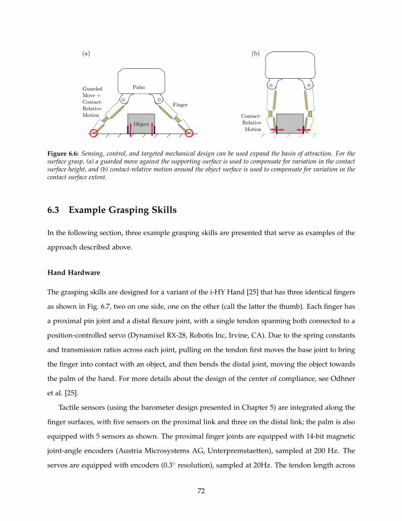
Finger
Palm
Object
Guarded
Move +
Contact-
Relative
Motion Contact-
Relative
Motion
(a) (b)
Figure 6.6: Sensing, control, and targeted mechanical design can be used expand the basin of attraction. For thesurface grasp, (a) a guarded move against the supporting surface is used to compensate for variation in the contactsurface height, and (b) contact-relative motion around the object surface is used to compensate for variation in thecontact surface extent.
6.3 Example Grasping Skills
In the following section, three example grasping skills are presented that serve as examples of the
approach described above.
Hand Hardware
The grasping skills are designed for a variant of the i-HY Hand [25] that has three identical fingers
as shown in Fig. 6.7, two on one side, one on the other (call the latter the thumb). Each finger has
a proximal pin joint and a distal flexure joint, with a single tendon spanning both connected to a
position-controlled servo (Dynamixel RX-28, Robotis Inc, Irvine, CA). Due to the spring constants
and transmission ratios across each joint, pulling on the tendon first moves the base joint to bring
the finger into contact with an object, and then bends the distal joint, moving the object towards
the palm of the hand. For more details about the design of the center of compliance, see Odhner
et al. [25].
Tactile sensors (using the barometer design presented in Chapter 5) are integrated along the
finger surfaces, with five sensors on the proximal link and three on the distal link; the palm is also
equipped with 5 sensors as shown. The proximal finger joints are equipped with 14-bit magnetic
joint-angle encoders (Austria Microsystems AG, Unterpremstaetten), sampled at 200 Hz. The
servos are equipped with encoders (0.3 resolution), sampled at 20Hz. The tendon length across
72
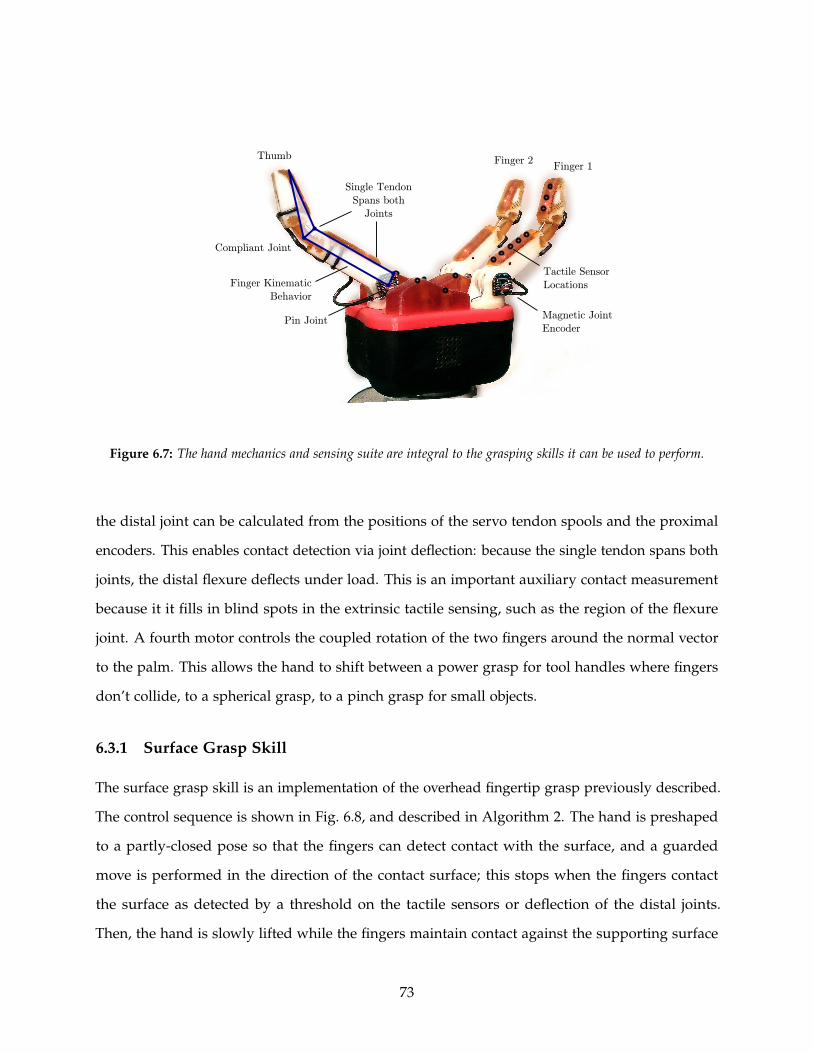
Pin Joint
Compliant Joint
Single Tendon
Spans both
Joints
Finger Kinematic
Behavior
Thumb Finger 2Finger 1
Tactile Sensor
Locations
Magnetic Joint
Encoder
Figure 6.7: The hand mechanics and sensing suite are integral to the grasping skills it can be used to perform.
the distal joint can be calculated from the positions of the servo tendon spools and the proximal
encoders. This enables contact detection via joint deflection: because the single tendon spans both
joints, the distal flexure deflects under load. This is an important auxiliary contact measurement
because it it fills in blind spots in the extrinsic tactile sensing, such as the region of the flexure
joint. A fourth motor controls the coupled rotation of the two fingers around the normal vector
to the palm. This allows the hand to shift between a power grasp for tool handles where fingers
don’t collide, to a spherical grasp, to a pinch grasp for small objects.
6.3.1 Surface Grasp Skill
The surface grasp skill is an implementation of the overhead fingertip grasp previously described.
The control sequence is shown in Fig. 6.8, and described in Algorithm 2. The hand is preshaped
to a partly-closed pose so that the fingers can detect contact with the surface, and a guarded
move is performed in the direction of the contact surface; this stops when the fingers contact
the surface as detected by a threshold on the tactile sensors or deflection of the distal joints.
Then, the hand is slowly lifted while the fingers maintain contact against the supporting surface
73

(a) (b) (c) (d)
Figure 6.8: The surface grasp consists of (a) orienting the hand over the object, (b) performing a guarded movetowards the surface, (c) slowly lifting the arm while the fingers maintain contact with the surface until the object isdetected by the change of finger closure rate, and (d) tightening of the grasp for a firm hold.
using contact sensing. Like the method presented by Kazemi [102], this relies on sliding fingers
against a supporting surface to ensure the fingertips catch the object edges, but it does so using a
position-controlled arm without strain-gauge sensors. Eventually, the fingers contact the object;
this is detected by the change in closure rate of the base angles using a strategy inspired by [36].
Finally, the tendons are tightened to secure the grasp, and the skill is complete.
Algorithm 2 Surface Grasp Skill
1: Determine object centroid (x, y) and major axis θ in the plane of the supporting surface withthe perception system
2: Move arm over object (x, y) and align hand to object major axis θ3: Preshape hand so it can detect contact through tactile sensing and joint deflection4: Execute guarded move towards supporting surface; stop when contact is detected5: Switch hand into ’maintain contact’ mode (for each finger, tighten the tendon as long as it
does not sense contact)6: repeat7: Lift arm by STEP8: Wait (for fingers to stop)9: Read finger base angles
10: until Finger base angles stop increasing11: Tighten fingers
To demonstrate the validity of the bounds calculations, an object (allen wrench, dimensions
114.5 × 33.5 × 29 mm) was grasped under a variety of position offsets, and the success rate
recorded. According to calculations, the permissible x-offset is ±65mm and the experimental
results closely match this at ±50mm as shown in Fig. 6.9.
74
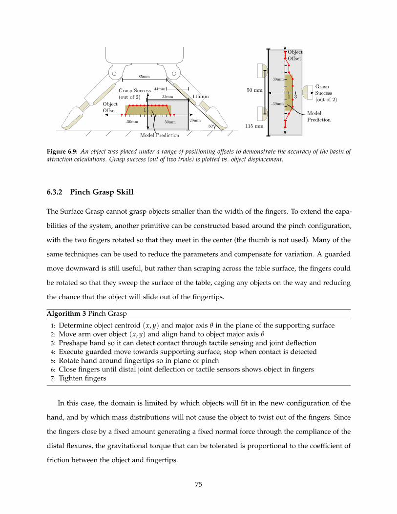
29mm
33mm
85mm
50o
Grasp Success
(out of 2) 115mm
44mm
115 mm
50 mm
50mm-50mm
1
Object
Offset
30mm
-30mm
1 3
Grasp
Success
(out of 2)
Object
Offset
Model
Prediction
Model Prediction
Figure 6.9: An object was placed under a range of positioning offsets to demonstrate the accuracy of the basin ofattraction calculations. Grasp success (out of two trials) is plotted vs. object displacement.
6.3.2 Pinch Grasp Skill
The Surface Grasp cannot grasp objects smaller than the width of the fingers. To extend the capa-
bilities of the system, another primitive can be constructed based around the pinch configuration,
with the two fingers rotated so that they meet in the center (the thumb is not used). Many of the
same techniques can be used to reduce the parameters and compensate for variation. A guarded
move downward is still useful, but rather than scraping across the table surface, the fingers could
be rotated so that they sweep the surface of the table, caging any objects on the way and reducing
the chance that the object will slide out of the fingertips.
Algorithm 3 Pinch Grasp
1: Determine object centroid (x, y) and major axis θ in the plane of the supporting surface2: Move arm over object (x, y) and align hand to object major axis θ3: Preshape hand so it can detect contact through tactile sensing and joint deflection4: Execute guarded move towards supporting surface; stop when contact is detected5: Rotate hand around fingertips so in plane of pinch6: Close fingers until distal joint deflection or tactile sensors shows object in fingers7: Tighten fingers
In this case, the domain is limited by which objects will fit in the new configuration of the
hand, and by which mass distributions will not cause the object to twist out of the fingers. Since
the fingers close by a fixed amount generating a fixed normal force through the compliance of the
distal flexures, the gravitational torque that can be tolerated is proportional to the coefficient of
friction between the object and fingertips.
75

Guarded Move
Place Fingers
Contact-Relative Motion
Roll Object onto Fingertips Release Finger 2
Guarded Move
Re-Apply Finger 2
Figure 6.10: The fingerwalk manipulation leverages contact-relative motion and passive mechanics to transition theobject from a fingertip grasp to a power grasp with no global information about object shape or size.
6.3.3 Fingerwalk Manipulation
This same framework can be applied to creating discrete manipulation primitives. The goal again
is to create a capability that functions across a range of local variations.
One important manipulation is the ability to shift an object from a fingertip pinch (useful for
lifting objects off supporting surfaces) to a power grasp against the palm (a stronger grasp more
suited to tool use). In the i-HY hand, the fingertips’ centers of compliance are designed so that
the fingers first close against an object, and then under further tendon retraction, the distal joints
bend and roll the object onto their tips, moving it towards the palm as shown in Fig. 6.10. By
maintaining the grasp with one finger and releasing the other, this primitive can be gaited to roll
the object into the hand.
Algorithm 4 Fingerwalk Manipulation
1: Close fingers onto object surface2: Tighten fingers to roll object onto fingertips (fixed amount)3: repeat4: for Finger in Finger1, Finger2 do5: Open Finger by enough to release (fixed amount)6: Close finger until contact7: Tighten finger again to roll object onto fingertip8: end for9: until PROXIMAL CONTACT or PALM CONTACT or TIMEOUT
Several parameters must be set to successfully execute this grasp. Setting them automatically
around the object surface creates a local basin of attraction for tolerated variation in the object’s
76
geometry. The reference point around which to tighten the tendons is set by starting the skill with
a contact-relative closure of the fingers. The amount to tighten the fingers can be fixed. Another
parameter is the amount by which the finger must be loosened for the distal flexure to overcome
surface friction; a fixed tendon length is again sufficient as shown in Fig. 6.10. The final parameter
is the number of times to execute this cycle to bring the object into the hand. The distal link ceases
to move the object if they are no longer in contact, and the object cannot move closer than the
palm, so tactile sensing is used to detect either termination condition. A time-out after n cycles is
used to detect pathological cases that do not resolve.
The specifics of the skill again provide a good way to understand the bounds of the basin of
attraction across which the skill can be applied. For the first phase of the skill, it is necessary
to create a three-fingered grasp on the object, which means the object must fit inside the hand
and the contact surfaces must be inside the friction cones of the fingers, much as in the surface
grasp. When one finger is released, the resulting finger-thumb pinch must be stable enough that
the object does not maintain contact with the released finger or eject; this requires either surface
patch geometry in a certain range or a secondary support (such as provided by friction against
a supporting surface) is required. Finally, the profile of the object must not block the extension
of the finger as it walks up the object – an interfering geometric feature will cause it to fail, for
example.
6.4 Conclusion
In this chapter, I present a framework that uses variation as a lens to understand generality
in robot grasping. First, I demonstrate that system’s ability to overcome variation provides a
way to compare and evaluate the capabilities of different grasping systems and apply it to a
collection of leading examples. Second, I present a methodology for designing grasping systems
based on the observation that it is easier to design around local variation than to create effective
parameterizations of global variation. Creating a basin of attraction around template grasps
provides a local context that makes it tractable to understand which sources of variation are
important and their effects on system performance. This creates a "basin of attraction" within
which successful grasps can be achieved. Finally, I show that these basins of attraction can be
77
used as a "variation budget" to understand the tradoffs between different subsystems such as the
perception system and the robot arm. This is an important step to move from ad hoc approaches
towards more rigorous system design and analysis.
78

Chapter 7
Conclusion and Future Directions
7.1 Summary
In this thesis, I present sensor designs and control strategies that enable robots with simple
hardware to robustly grasp objects in unstructured environments. Designing robust grasping and
manipulation systems is a complex problem due to the challenge of compensating for the many
sources of variation that affect grasping in unstructured environments, and the current solutions
are also frequently complex. In particular, many require perception systems to obtain detailed
models of the world and precise hand hardware to execute the plans created on this information.
This is a barrier both to the more widespread use of grasping systems in applications beyond
research, and also to an understanding of how tradeoffs within different subsystems affect overall
performance.
In Chapter 2, I present a way to compensate for planar variation in object pose and shape
with pizeoelectric contact sensors and an alignment algorithm on an underactuated hand. This
reduces the precision required from the perception system and robot arm. In Chapter 3, I present
designs to integrate joint-angle sensors into flexure joints which passively adapt to the geometry of
grasped objects; these provide a way to detect contact and determine object geometry under simple
control, as shown in Chapter 4. In Chapter 5, I analyze the limitations of fixed compliance to
compensate for variation in object position and demonstrate the benefits of an alternate approach
based on highly-sensitive tactile sensors created from MEMS barometers. Finally, in Chapter 6, I
show that posing the grasping problem as overcoming variation provides a cohesive framework
79
to explain the tradeoffs between and within disparate systems, and present a methodology to
design variation-tolerant systems by creating template grasps that tolerate local variation. The
template grasp provides essential context to understand the bounds of tolerated variation (the
"basin of attraction" for the grasp template), and can be treated as a "variation budget" that can
be distributed among the sources of variation in the system including the object, the perception
system, and the robot hardware.
7.2 Specific Contributions
• The design of joint-angle sensors for multi-DOF flexure joints that adapt to objects and the
environment
• The design of high-sensitivity tactile sensors that are simple to manufacture and integrate
into robot designs
• The creation and evaluation of control strategies that compensate for limited perception and
positioning errors in robot grasping
• A framework to understand and evaluate the capabilities of robotic grasping systems in
terms of the variation they overcome
• A design methodology for creating new capabilities around template grasps that provide
context to understand the impact of variation and how to correct it
7.3 Future Directions
This research opens a number of directions for further exploration. Sliding Manipulation - Humans
make extensive use of sliding and rolling contact while they aquire grasps and manipulate
objects. Sliding motions move across surfaces faster than guarded moves, and are particularly
advantageous for exploring the occluded side of objects during grasp acquisition. Although a
number of structured experiments have demonstrated control of sliding contact with robots (e.g.,
those by Grupen et al. [75]), it is difficult to achieve the low force levels required for effective
operation in practical applications. Using highly-compliant fingers with joint-angle sensors as
80

presented in Chapter 4 would allow the passive mechanics to perform the low-level control and
reduce the requirements on force measurements, which might be made with the joints themselves
or with the tactile sensors presented in Chapter 5.
Active Perception - the perception system introduces variation when it creates imprecise or
inaccurate internal models from the world, but it also reduces variation by creating a more
complete model of the world. One way to improve the precision and scope of the world model is
through active perception – performing actions for the purpose of gathering information about
the world [126]. Soft fingers and sensitive sensors make this easier because errors do not cause
robot damage and because they relax the precision required of the control system. This might be
especially useful in the context of grasp acquisition to position fingers on the occluded side of the
object, or to separate different items during bin picking.
Machine learning - The ability to equip mechanically robust, compliant hands with effective
sensing will enable more aggressive applications of machine learning for grasping in unstructured
environment. Until now, the fragility of robot hardware has restricted such studies to carefully
controlled tasks to avoid damage to the robot or the environment. Compliant joints deform under
load rather than breaking, and the tactile sensors presented in Chapter 5 are able to withstand
high loads. This means algorithms can be trained on a wider range of experiences. Such trials
are particularly important for creating effective classifiers to detect failure. Such classifiers would
enable better sequencing of different action primitives and corrections together to perform more
complicated tasks.
Manipulation - The fingerwalk primitive presented in Chapter 6 demonstrates that the frame-
work can be applied to creating robust manipulation skills that work across a space of variation
around a template manipulation. This framework could be used to create tractable stereotyped
capabilities for applications such as assembly in manufacturing and assistance. The context
provided by specific skills would also provide the ability to evaluate the complexity-performance
tradeoffs involved in adding additional actuators to the hand design. There is an interesting
tradeoff in capabilities between robot hands and arms. Humans use their fingers for fine skills
and their arms for larger motions, but robot arms are typically highly precise and can perform
many operations humans perform with their fingers. Limitations in the robot arm’s workspace
(especially towards the edges) may dictate which in-hand manipulation is most important. Con-
81

versely, the development of better in-hand capabilities for robots may enable the use of lower-cost
less precise arms.
Skill Libraries - the template grasps and manipulations presented in Chapter 6 provide a
starting point for effective grasping in unstructured environments, but are far from comprehensive.
Creating a wider set of template grasps and manipulations is an obvious (and interesting) direction
for future study.
Optimized System Designs - the idea of variation budgets presented in Chapter 6 can be used
to optimize the entire grasping system to achieve a given level of functionality. Applying this
approach in the context of specific template grasps across the entire system design will reduce the
complexity and cost of grasping systems by making it more clear where to use techniques such as
targeted compliance can be used to simplify systems.
Looking forward to the future, it is important to open the capabilities of robotics to those with
less domain knowledge so robotics can be applied to solve a wider range of societal problems.
Personal computers transformed secretaries’ work in the 1980s when they became inexpensive
enough and easy enough to use – rather than replacing their jobs, they served as an empowering
technology that enabled them to focus on the more interesting, more important parts of the
problem. Robotics stands poised to create the same revolution for factory workers in short-run
manufacturing companies, first responders working in dangerous conditions, and the elderly
seeking to maintain their independence. Grasping is a critical capability for performing many of
these tasks, and the hardware designs and conceptual framework presented here will result in
simpler, more capable systems that function robustly across the variation in the real world.
82
References
[1] I. Suitable Technologies, “The beam pro.” https://www.suitabletech.com/beam/. Accessed:2014-04-16.
[2] M. Raibert, K. Blankespoor, G. Nelson, and R. Playter, “the big-dog team (2008) bigdog, therough-terrain quadruped robot,” in Proceedings of the 17th World Congress, The InternationalFederation of Automatic Control, 2008.
[3] G. Pratt and J. Manzo, “The darpa robotics challenge [competitions],” Robotics & AutomationMagazine, IEEE, vol. 20, no. 2, pp. 10–12, 2013.
[4] T. Hornyak, “irobot sucks up mint maker evolution robotics.”http://www.cnet.com/news/irobot-sucks-up-mint-maker-evolution-robotics/, 2012.Accessed:.
[5] T. Simonite, “Data shows google’s robot cars are smoother, safer drivers than you ori.” http://www.technologyreview.com/news/520746/data-shows-googles-robot-cars-are-smoother-safer-drivers-than-you-or-i/, 2013. Accessed: 2014-05-14.
[6] M. McClelland, “I was a warehouse wage slave.”http://www.motherjones.com/politics/2012/02/mac-mcclelland-free-online-shipping-warehouses-labor, 2012. Accessed: 2014-04-14.
[7] L. Righetti, M. Kalakrishnan, P. Pastor, J. Binney, J. Kelly, R. C. Voorhies, G. S. Sukhatme, andS. Schaal, “An autonomous manipulation system based on force control and optimization,”Autonomous Robots, vol. 36, no. 1-2, pp. 11–30, 2014.
[8] A. T. Miller and P. K. Allen, “Graspit! a versatile simulator for robotic grasping,” Robotics &Automation Magazine, IEEE, vol. 11, no. 4, pp. 110–122, 2004.
[9] R. Diankov and J. Kuffner, “Openrave: A planning architecture for autonomous robotics,”Robotics Institute, Pittsburgh, PA, Tech. Rep. CMU-RI-TR-08-34, p. 79, 2008.
[10] J. Weisz and P. Allen, “Pose error robust grasping from contact wrench space metrics,” inRobotics and Automation (ICRA), 2012 IEEE International Conference on, pp. 557–562, May 2012.
[11] K. Hsiao, S. Chitta, M. Ciocarlie, and E. Jones, “Contact-reactive grasping of objects with par-tial shape information,” in Intelligent Robots and Systems (IROS), 2010 IEEE/RSJ InternationalConference on, pp. 1228–1235, 2010.
[12] E. Klingbeil, D. Rao, B. Carpenter, V. Ganapathi, A. Ng, and O. Khatib, “Grasping withapplication to an autonomous checkout robot,” in Robotics and Automation (ICRA), 2011 IEEEInternational Conference on, pp. 2837–2844, May 2011.
83

[13] A. Herzog, P. Pastor, M. Kalakrishnan, L. Righetti, J. Bohg, T. Asfour, and S. Schaal,“Learning of grasp selection based on shape-templates,” Autonomous Robots, vol. 36, no. 1-2,pp. 51–65, 2014.
[14] R. Balasubramanian, L. Xu, P. D. Brook, J. R. Smith, and Y. Matsuoka, “Human-guided graspmeasures improve grasp robustness on physical robot,” in Robotics and Automation (ICRA),2010 IEEE International Conference on, pp. 2294–2301, IEEE, 2010.
[15] A. Kochan, “Shadow delivers first hand,” Industrial Robot: an International Journal, vol. 32,no. 1, pp. 15–16, 2005.
[16] F. Stulp, E. Theodorou, J. Buchli, and S. Schaal, “Learning to grasp under uncertainty,” inRobotics and Automation (ICRA), 2011 IEEE International Conference on, pp. 5703–5708, IEEE,2011.
[17] T. Laliberte, L. Birglen, and C. Gosselin, “Underactuation in robotic grasping hands,”Machine Intelligence & Robotic Control, vol. 4, no. 3, pp. 1–11, 2002.
[18] A. M. Dollar and R. D. Howe, “The highly adaptive sdm hand: Design and performanceevaluation,” The International Journal of Robotics Research, vol. 29, no. 5, pp. 585–597, 2010.
[19] “Robotiq adaptive gripper 3-finger model.” http://robotiq.com/media/Robotiq-3-Finger-Adaptive-Robot-Gripper-Specifications.pdf, 2013. Accessed: 2014-05-14.
[20] D. Aukes, S. Kim, P. Garcia, A. Edsinger, and M. Cutkosky, “Selectively compliant un-deractuated hand for mobile manipulation,” in Robotics and Automation (ICRA), 2012 IEEEInternational Conference on, pp. 2824–2829, May 2012.
[21] S. Hirose and Y. Umetani, “The development of soft gripper for the versatile robot hand,”Mechanism and machine theory, vol. 13, no. 3, pp. 351–359, 1978.
[22] R. Mahmoud, A. Ueno, and S. Tatsumi, “An assistive tele-operated anthropomorphic robothand: Osaka city university hand ii,” in Human-Robot Interaction (HRI), 2011 6th ACM/IEEEInternational Conference on, pp. 85–92, 2011.
[23] T. Mouri, H. Kawasaki, K. Yoshikawa, J. Takai, and S. Ito, “Anthropomorphic robot hand:Gifu hand iii,” in Proc. Int. Conf. ICCAS, pp. 1288–1293, 2002.
[24] J. Butterfaß, M. Grebenstein, H. Liu, and G. Hirzinger, “Dlr-hand ii: Next generation ofa dextrous robot hand,” in Robotics and Automation, 2001. Proceedings 2001 ICRA. IEEEInternational Conference on, vol. 1, pp. 109–114, IEEE, 2001.
[25] L. Odhner, L. P. Jentoft, M. R. Claffee, N. Corson, Y. Tenzer, R. R. Ma, M. Buehler, R. Kohout,R. D. Howe, and A. M. Dollar, “A compliant, underactuated hand for robust manipulation,”IJRR (under review, available anonymously at http://arxiv.org/abs/1301.4394), vol. abs/1301.4394,2013.
[26] R. R. Ma, L. U. Odhner, and A. M. Dollar, “Dexterous manipulation with underactuatedfingers: Flip-and-pinch task,” in Robotics and Automation (ICRA), 2012 IEEE InternationalConference on, pp. 3551–3552, IEEE, 2012.
[27] C. Ferrari and J. Canny, “Planning optimal grasps,” in Robotics and Automation, 1992.Proceedings., 1992 IEEE International Conference on, pp. 2290–2295, IEEE, 1992.
84
[28] A. Bicchi and V. Kumar, “Robotic grasping and contact: a review,” in Robotics and Automation,2000. Proceedings. ICRA ’00. IEEE International Conference on, vol. 1, pp. 348–353 vol.1, 2000.
[29] P. C. Gaston and T. Lozano-Perez, “Tactile recognition and localization using object models:The case of polyhedra on a plane,” Pattern Analysis and Machine Intelligence, IEEE Transactionson, no. 3, pp. 257–266, 1984.
[30] K. Hsiao, T. Lozano-Pérez, and L. P. Kaelbling, “Robust belief-based execution of manipula-tion programs,” in Eighth Intl. Workshop on the Algorithmic Foundations of Robotics, Citeseer,2008.
[31] H. Maekawa, K. Tanie, K. Komoriya, M. Kaneko, C. Horiguchi, and T. Sugawara, “Develop-ment of a finger-shaped tactile sensor and its evaluation by active touch,” in Robotics andAutomation, 1992. Proceedings., 1992 IEEE International Conference on, pp. 1327–1334, IEEE,1992.
[32] R. Platt, A. Fagg, and R. Grupen, “Null-space grasp control: Theory and experiments,”Robotics, IEEE Transactions on, vol. 26, pp. 282–295, April 2010.
[33] A. Miller, S. Knoop, H. Christensen, and P. Allen, “Automatic grasp planning using shapeprimitives,” in Robotics and Automation, 2003. Proceedings. ICRA ’03. IEEE International Confer-ence on, vol. 2, pp. 1824–1829 vol.2, Sept 2003.
[34] K. Hsiao, S. Chitta, M. Ciocarlie, and E. G. Jones, “Contact-reactive grasping of objectswith partial shape information,” in Intelligent Robots and Systems (IROS), 2010 IEEE/RSJInternational Conference on, pp. 1228–1235, IEEE, 2010.
[35] L. Natale and E. Torres-Jara, “A sensitive approach to grasping,” in Proceedings of the sixthinternational workshop on epigenetic robotics, pp. 87–94, Citeseer, 2006.
[36] J. Felip and A. Morales, “Robust sensor-based grasp primitive for a three-finger robothand,” in Intelligent Robots and Systems, 2009. IROS 2009. IEEE/RSJ International Conference on,pp. 1811–1816, IEEE, 2009.
[37] A. Maldonado, U. Klank, and M. Beetz, “Robotic grasping of unmodeled objects usingtime-of-flight range data and finger torque information,” in Intelligent Robots and Systems(IROS), 2010 IEEE/RSJ International Conference on, pp. 2586–2591, IEEE, 2010.
[38] A. Dollar, L. Jentoft, J. Gao, and R. Howe, “Contact sensing and grasping performance ofcompliant hands,” Autonomous Robots, vol. 28, pp. 65–75, 2010.
[39] R. Merz, F. Prinz, K. Ramaswami, M. Terk, and L. Weiss, Shape deposition manufacturing.Engineering Design Research Center, Carnegie Mellon Univ., 1994.
[40] R. Tomovic, G. A. Bekey, and W. J. Karplus, “A strategy for grasp synthesis with multifin-gered robot hands,” in Robotics and Automation. Proceedings. 1987 IEEE International Conferenceon, vol. 4, pp. 83–89, IEEE, 1987.
[41] R. Howe, N. Popp, P. Akella, I. Kao, and M. Cutkosky, “Grasping, manipulation, and controlwith tactile sensing,” in Robotics and Automation, 1990. Proceedings., 1990 IEEE InternationalConference on, pp. 1258–1263 vol.2, May 1990.
85

[42] J. M. Hyde, M. R. Tremblay, and M. R. Cutkosky, “An object-oriented framework forevent-driven dextrous manipulation,” in Experimental Robotics IV, pp. 51–61, Springer, 1997.
[43] A. Dollar and R. Howe, “The sdm hand as a prosthetic terminal device: A feasibility study,”in Rehabilitation Robotics, 2007. ICORR 2007. IEEE 10th International Conference on, pp. 978–983,June 2007.
[44] O. Khatib, “Mobile manipulation: The robotic assistant,” Robotics and Autonomous Systems,vol. 26, no. 2, pp. 175–183, 1999.
[45] A. Saxena, J. Driemeyer, and A. Y. Ng, “Robotic grasping of novel objects using vision,” TheInternational Journal of Robotics Research, vol. 27, no. 2, pp. 157–173, 2008.
[46] C. C. Kemp, C. D. Anderson, H. Nguyen, A. J. Trevor, and Z. Xu, “A point-and-click interfacefor the real world: laser designation of objects for mobile manipulation,” in Human-RobotInteraction (HRI), 2008 3rd ACM/IEEE International Conference on, pp. 241–248, IEEE, 2008.
[47] D. Braun, J. Mitchell, and M. Goldfarb, “Actuated dynamic walking in biped robots: Controlapproach, robot design and experimental validation,” in Humanoid Robots, 2009. Humanoids2009. 9th IEEE-RAS International Conference on, pp. 237–242, Dec 2009.
[48] H.-W. Park, K. Sreenath, J. Hurst, and J. Grizzle, “Identification of a bipedal robot with acompliant drivetrain,” Control Systems, IEEE, vol. 31, pp. 63–88, April 2011.
[49] M. Grimmer, M. Eslamy, S. Gliech, and A. Seyfarth, “A comparison of parallel- and serieselastic elements in an actuator for mimicking human ankle joint in walking and running,”in Robotics and Automation (ICRA), 2012 IEEE International Conference on, pp. 2463–2470, May2012.
[50] A. M. Dollar and R. D. Howe, “A robust compliant grasper via shape deposition manufac-turing,” IEEE/ASME Transactions on Mechatronics, vol. 11, no. 2, pp. 154–161, 2006.
[51] J. E. Clark, J. G. Cham, S. A. Bailey, E. M. Froehlich, P. K. Nahata, R. J. Full, and M. R.Cutkosky, “Biomimetic design and fabrication of a hexapedal running robot,” in Proceedingsof the 2001 IEEE International Conference on Robotics and Automation (ICRA’01), vol. 4, pp. 3643–3649, IEEE, 2001.
[52] F. Lotti, P. Tiezzi, G. Vassura, L. Biagiotti, G. Palli, and C. Melchiorri, “Development ofub hand 3: Early results,” Proc. IEEE Int. Conf. Robotics and Automation 2005 (ICRA 2005),pp. 4488 – 4493, apr. 2005.
[53] M. A. Minor and R. Merrell, “Instrumentation and algorithms for posture estimation incompliant framed modular mobile robots,” The International Journal of Robotics Research,vol. 26, no. 5, pp. 491–512, 2007.
[54] L. I. Incorporated, “Fiber optic shape sensing.” http://lunainc.com/growth-area/fiber-optic-shape-sensing/. Accessed: 2014-03-29.
[55] L. P. Jentoft and R. D. Howe, “Compliant fingers make simple sensors smart,” in Proc. 2010IFToMM / ASME Workshop on Underactuated Grasping (UG2010), Monteal, Canada, Aug. 192010.
86

[56] R. Ballarini, “The da vinci-euler-bernoulli beam theory?,” Mechanical Engineering The Maga-zine of ASME. http://memagazine. asme. org/web/Da VinciEulerBernoulli Beam. cfm (20/10/2012),vol. 35, 2006.
[57] S. P. Timoshenko and J. M. Gere, Theory of elastic stability. Courier Dover Publications, 2012.
[58] L. U. Odhner and A. M. Dollar, “Toward simpler models of bending sheet joints,” inIntelligent Robots and Systems (IROS), 2011 IEEE/RSJ International Conference on, pp. 1420–1426,IEEE, 2011.
[59] M. H. Raibert and J. J. Craig, “Hybrid position/force control of manipulators,” Journal ofDynamic Systems, Measurement, and Control, vol. 103, no. 2, pp. 126–133, 1981.
[60] N. Hogan, “Impedance control: An approach to manipulation: Part ii—implementation,”Journal of dynamic systems, measurement, and control, vol. 107, no. 1, pp. 8–16, 1985.
[61] A. J. Ijspeert, J. Nakanishi, and S. Schaal, “Learning attractor landscapes for learning motorprimitives,” Advances in neural information processing systems, pp. 1547–1554, 2003.
[62] S. Schaal, J. Peters, J. Nakanishi, and A. Ijspeert, “Learning movement primitives,” in RoboticsResearch, pp. 561–572, Springer, 2005.
[63] J. Pratt, B. Krupp, and C. Morse, “Series elastic actuators for high fidelity force control,”Industrial Robot: An International Journal, vol. 29, no. 3, pp. 234–241, 2002.
[64] J. E. Pratt and G. A. Pratt, “Exploiting natural dynamics in the control of a planar bipedalwalking robot,” in PROCEEDINGS OF THE ANNUAL ALLERTON CONFERENCE ONCOMMUNICATION CONTROL AND COMPUTING, vol. 36, pp. 739–748, UNIVERSITY OFILLINOIS, 1998.
[65] G. A. Pratt, “Legged robots at mit: what’s new since raibert?,” Robotics & AutomationMagazine, IEEE, vol. 7, no. 3, pp. 15–19, 2000.
[66] A. Edsinger-Gonzales and J. Weber, “Domo: a force sensing humanoid robot for manipu-lation research,” in Humanoid Robots, 2004 4th IEEE/RAS International Conference on, vol. 1,pp. 273–291, IEEE, 2004.
[67] R. Robotics, “Baxter manufacturing robot,” 2012.
[68] E. Torres-Jara, “Obrero: A platform for sensitive manipulation,” in Humanoid Robots, 20055th IEEE-RAS International Conference on, pp. 327–332, IEEE, 2005.
[69] K. Hsiao, L. Kaelbling, and T. Lozano-Perez, “Grasping pomdps,” in Proc. IEEE Int. Conf.Robotics and Automation 2007 (ICRA 2007), pp. 4685 –4692, April 2007.
[70] A. Okamura and M. Cutkosky, “Haptic exploration of fine surface features,” in Proc. IEEEInt. Conf. Robotics and Automation 1999 (ICRA 1999), vol. 4, pp. 2930 – 2936, 1999.
[71] R. Russell, “Using tactile whiskers to measure surface contours,” in Proc. IEEE Int. Conf.Robotics and Automation 1992 (ICRA 1992), pp. 1295 –1299 vol.2, May 1992.
[72] D. Hristu, N. Ferrier, and R. Brockett, “The performance of a deformable-membrane tactilesensor: basic results on geometrically-defined tasks,” in Proc. 2000 IEEE Int. Conf. Roboticsand Automation, 2000. (ICRA 2000), vol. 1, pp. 508–513, 2000.
87

[73] S. Hirose, S. Inoue, and K. Yoneda, “The whisker sensor and the transmission of multiplesensor signals,” Advanced Robotics, vol. 4, no. 2, pp. 105–117, 1989.
[74] M. Kaneko and K. Tanie, “Contact point detection for grasping of an unknown object usingself-posture changeability (spc),” in Proc. IEEE Int. Conf. Robotics and Automation 1990 (ICRA1990), pp. 864 –869 vol.2, May 1990.
[75] R. Grupen and M. Huber, “2-d contact detection and localization using proprioceptiveinformation,” in Proc. IEEE Int. Conf. Robotics and Automation 1993 (ICRA 1993), pp. 130 –135vol.2, May 1993.
[76] T. Tsujimura and T. Yabuta, “Object detection by tactile sensing method employingforce/torque information,” IEEE Trans. Robotics and Automation, vol. 5, pp. 444 –450, Aug.1989.
[77] H. R. Nicholls and M. H. Lee, “A survey of robot tactile sensing technology,” The Int. Journalof Robotics Research, vol. 8, no. 3, pp. 3–30, 1989.
[78] R. Dahiya, G. Metta, M. Valle, and G. Sandini, “Tactile sensing - from humans to humanoids,”IEEE Trans. Robotics, vol. 26, no. 1, pp. 1–20, 2007.
[79] P. Allen and P. Michelman, “Acquisition and interpretation of 3-d sensor data from touch,”IEEE Trans. Robotics and Automation, vol. 6, pp. 397 – 404, August 1990.
[80] Y.-B. Jia, L. Mi, and J. Tian, “Surface patch reconstruction via curve sampling,” in Proc. IEEEInt. Conf. Robotics and Automation 2006 (ICRA 2006), pp. 1371 –1377, May 2006.
[81] P. C. Gaston and T. Lozano-Perez, “Tactile recognition and localization using object models:The case of polyhedra on a plane,” IEEE Trans. Pattern Analysis and Machine Intelligence,vol. PAMI-6, pp. 257 –266, May 1984.
[82] R. S. Fearing, Tactile sensing for shape interpretation, pp. 209–238. New York, NY, USA:Springer-Verlag New York, Inc., 1990.
[83] M. Moll and M. Erdmann, “Reconstructing shape from motion using tactile sensors,” Proc.2001 IEEE/RSJ Int. Conf. Intelligent Robots and Systems, IROS 2001., vol. 2, pp. 692 –700 vol.2,2001.
[84] H. Samet, “The quadtree and related hierarchical data structures,” ACM Computing Surveys(CSUR), vol. 16, no. 2, pp. 187–260, 1984.
[85] M. Kaneko, N. Kanayama, and T. Tsuji, “3-d active antenna for contact sensing,” in Proc.IEEE Int. Conf. Robotics and Automation 1995 (ICRA 1995), vol. 1, pp. 1113 –1119 vol.1, May1995.
[86] G. Scholz and C. Rahn, “Profile sensing with an actuated whisker,” IEEE Trans. Robotics andAutomation, vol. 20, no. 1, pp. 124 – 127, 2004.
[87] A. Schultz, J. Solomon, M. Peshkin, and M. Hartmann, “Multifunctional whisker arrays fordistance detection, terrain mapping, and object feature extraction,” in Proc. IEEE Int. Conf.Robotics and Automation 2005 (ICRA 2005), pp. 2588 – 2593, April 2005.
[88] M. Hartmann, “Active sensing capabilities of the rat whisker system,” Autonomous Robots,vol. 11, pp. 249–254, 2001.
88

[89] S. Anderson, M. Pearson, A. Pipe, T. Prescott, P. Dean, and J. Porrill, “Adaptive cancelationof self-generated sensory signals in a whisking robot,” IEEE Trans. Robotics, vol. 26, no. 6,pp. 1065 –1076, 2010.
[90] N. Ueno and M. Kaneko, “Dynamic active antenna - a principle of dynamic sensing,” inProc. IEEE Int. Conf. Robotics and Automation 1994 (ICRA1994), pp. 1784 –1790 vol.2, May1994.
[91] R. A. Russell and J. A. Wijaya, “Object location and recognition using whisker sensors,” inAustralian Conference on Robotics and Automation, CD-ROM Proceedings ISBN, pp. 0–9587583,2003.
[92] T. Clements and C. Rahn, “Three-dimensional contact imaging with an actuated whisker,”Robotics, IEEE Transactions on, vol. 22, pp. 844 –848, Aug. 2006.
[93] M. Briot, M. Renaud, and Z. STOJILJKOVIC, “An approach to spatial pattern recognition ofsolid objects,” IEEE Trans. Systems, Man and Cybernetics, vol. 8, pp. 690 –694, Sept. 1978.
[94] S. Caselli, C. Magnanini, and F. Zanichelli, “Investigation of polyhedral shape representationsand connectionist techniques in haptic object recognition,” in Proc. IEEE/RSJ/GI Int. Conf.Intelligent Robots and Systems ’94 (IROS ’94), vol. 1, pp. 232 –239 vol.1, Sept. 1994.
[95] P. Deckers, A. M. Dollar, and R. D. Howe, “Guiding grasping with proprioception andmarkov models,” in Int. Conf. Robotics, Science, and Systems (RSS), June 2007.
[96] G. S. Koonjul, G. J. Zeglin, and N. S. Pollard, “Measuring contact points from displacementswith a compliant articulated robot hand,” in Proc. 2011 Int. Conf. Robotics and Automation(ICRA 2011), 2011.
[97] A. Dollar and R. Howe, “Simple, robust autonomous grasping in unstructured environ-ments,” in 2007 IEEE Int. Conf. Robotics and Automation (ICRA2007), pp. 4693 –4700, april2007.
[98] A. Dollar and R. Howe, “Simple, robust autonomous grasping in unstructured environ-ments,” in 2007 IEEE Int. Conf. Robotics and Automation (ICRA2007), pp. 4693 –4700, april2007.
[99] F. Hammond, J. Weisz, A. de la Llera Kurth, P. K. Allen, and R. Howe, “Towards a designoptimization method for reducing the mechanical complexity of underactuated robotichands,” in Robotics and Automation (ICRA), 2012 IEEE International Conference on, pp. 2843–2850, 2012.
[100] M. Ciocarlie and P. Allen, “Data-driven optimization for underactuated robotic hands,” inRobotics and Automation (ICRA), 2010 IEEE International Conference on, pp. 1292–1299, 2010.
[101] F. Stulp, E. Theodorou, M. Kalakrishnan, P. Pastor, L. Righetti, and S. Schaal, “Learningmotion primitive goals for robust manipulation,” in Intelligent Robots and Systems (IROS),2011 IEEE/RSJ International Conference on, pp. 325–331, 2011.
[102] M. Kazemi, J. sebastien Valois, J. A. Bagnell, and N. Pollard, “Robust object grasping usingforce compliant motion primitives,” in In Robotics: Science and Systems, 2012.
89
[103] R. D. Howe, “Tactile sensing and control of robotic manipulation,” Advanced Robotics, vol. 8,pp. 245–261(17), 1993.
[104] M. Lee and H. Nicholls, “Tactile sensing for mechatronics—a state of the art survey,”Mechtronics, vol. 9, no. 9, pp. 1–31, 1999.
[105] Y. Ohmura, Y. Kuniyoshi, and A. Nagakubo, “Conformable and scalable tactile sensorskin for curved surfaces,” Proc. 2006 IEEE Int. Conf. Robotics and Automation (ICRA2006),pp. 1348–1353, 15-19 2006.
[106] Y. Tenzer, L. P. Jentoft, and R. D. Howe, “Inexpensive and easily customized tactile arraysensors using mems barometers chips,” IEEE Robotics and Automation Magazine, 2013.
[107] G. Lammel and J. Patzel, “Pressure sensors provide indoor competency for navigation,”Small Times, pp. 1–s4, 2009.
[108] Bosh Sensortec, “Bmp085 digital pressure sensor,” Datasheet, no. Oct, 2009.
[109] S. Freescale, “Mpl115a2 miniature i2c digital barometer,” Datasheet, 2010.
[110] N. Semiconductors, “Um10204 i2c-bus specification and user manual,” User Manual, vol. 4,no. February, 2012.
[111] L. P. Jentoft, Y. Tenzer, D. Vogt, J. Liu, R. J. Wood, and R. D. Howe, “Flexible, stretchabletactile arrays from mems barometers,” in Advanced Robotics (ICAR), 2013 16th InternationalConference on, pp. 1–6, IEEE, 2013.
[112] Y. Tenzer, L. P. Jentoft, and R. D. Howe, “Inexpensive and easily customized tactile arraysensors using mems barometers chips,” IEEE Robotics and Automation Magazine (Under Review,http://biorobotics.harvard.edu/pubs/2012/Tenzer2012.pdf), 2012.
[113] M. Dogar and S. Srinivasa, “Push-grasping with dexterous hands: Mechanics and a method,”in Intelligent Robots and Systems (IROS), 2010 IEEE/RSJ International Conference on, pp. 2123–2130, 2010.
[114] A. M. Dollar and R. D. Howe, “The highly adaptive sdm hand: Design and performanceevaluation,” The International Journal of Robotics Research, vol. 29, no. 5, pp. 585–597, 2010.
[115] B. Vanderborght, A. Albu-Schaffer, A. Bicchi, E. Burdet, D. Caldwell, R. Carloni, M. Catalano,G. Ganesh, M. Garabini, M. Grebenstein, G. Grioli, S. Haddadin, A. Jafari, M. Laffranchi,D. Lefeber, F. Petit, S. Stramigioli, N. Tsagarakis, M. Van Damme, R. Van Ham, L. C. Visser,and S. Wolf, “Variable impedance actuators: Moving the robots of tomorrow,” in IntelligentRobots and Systems (IROS), 2012 IEEE/RSJ International Conference on, pp. 5454–5455, 2012.
[116] J. A. Blaya and H. Herr, “Adaptive control of a variable-impedance ankle-foot orthosis toassist drop-foot gait,” Neural Systems and Rehabilitation Engineering, IEEE Transactions on,vol. 12, no. 1, pp. 24–31, 2004.
[117] G. Tonietti, R. Schiavi, and A. Bicchi, “Design and control of a variable stiffness actuatorfor safe and fast physical human/robot interaction,” in Robotics and Automation, 2005. ICRA2005. Proceedings of the 2005 IEEE International Conference on, pp. 526–531, IEEE, 2005.
90

[118] R. Schiavi, G. Grioli, S. Sen, and A. Bicchi, “Vsa-ii: A novel prototype of variable stiffnessactuator for safe and performing robots interacting with humans,” in Robotics and Automation,2008. ICRA 2008. IEEE International Conference on, pp. 2171–2176, IEEE, 2008.
[119] M. Richtsfeld and M. Zillich, “Grasping unknown objects based on 2.5d range data,” inAutomation Science and Engineering, 2008. CASE 2008. IEEE International Conference on, pp. 691–696, Aug 2008.
[120] M. T. Mason and J. K. Salisbury Jr, Robot hands and the mechanics of manipulation. MIT press,1985.
[121] M. Grebenstein, A. Albu-Schaffer, T. Bahls, M. Chalon, O. Eiberger, W. Friedl, R. Gruber,S. Haddadin, U. Hagn, R. Haslinger, H. Hoppner, S. Jorg, M. Nickl, A. Nothhelfer, F. Petit,J. Reill, N. Seitz, T. Wimbock, S. Wolf, T. Wusthoff, and G. Hirzinger, “The dlr hand armsystem,” in Robotics and Automation (ICRA), 2011 IEEE International Conference on, pp. 3175–3182, May 2011.
[122] D. Hackett, J. Pippine, A. Watson, C. Sullivan, and G. Pratt, “Foreword to the special issueon autonomous grasping and manipulation,” Autonomous Robots, vol. 36, no. 1-2, pp. 5–9,2014.
[123] N. Hudson, J. Ma, P. Hebert, A. Jain, M. Bajracharya, T. Allen, R. Sharan, M. Horowitz,C. Kuo, T. Howard, et al., “Model-based autonomous system for performing dexterous,human-level manipulation tasks,” Autonomous Robots, vol. 36, no. 1-2, pp. 31–49, 2014.
[124] J. Bagnell, F. Cavalcanti, L. Cui, T. Galluzzo, M. Hebert, M. Kazemi, M. Klingensmith,J. Libby, T. Y. Liu, N. Pollard, M. Pivtoraiko, J.-S. Valois, and R. Zhu, “An integratedsystem for autonomous robotics manipulation,” in Intelligent Robots and Systems (IROS), 2012IEEE/RSJ International Conference on, pp. 2955–2962, Oct 2012.
[125] A. Jain and C. C. Kemp, “El-e: an assistive mobile manipulator that autonomously fetchesobjects from flat surfaces,” Autonomous Robots, vol. 28, no. 1, pp. 45–64, 2010.
[126] R. Bajcsy, “Active perception,” Proceedings of the IEEE, vol. 76, pp. 966–1005, Aug 1988.
91