Senior Design Final Project Presentation Team FSAE · PDF fileSenior Design Final Project...
38
Senior Design Final Project Presentation Team FSAE Powertrain Presented By: Michael Honeychuck, William “Jay” Kistler, Nick Piacente, Adam Stager December 13 th 2010
Transcript of Senior Design Final Project Presentation Team FSAE · PDF fileSenior Design Final Project...

Senior Design Final Project Presentation
Team FSAE Powertrain Presented By: Michael Honeychuck, William “Jay” Kistler, Nick Piacente, Adam Stager
December 13th 2010
Supervisors
Team Sponsor:
Mr. Paul Schwarz Mainline Porsche, Newtown Square, PA Team Faculty Advisor:
Dr. Steve Timmins University of Delaware, ME Department

General Project Info
To aid in the production of the powertrain for the 2010-11 SAE car to compete in the annual FSAE competition next summer in California.
What is the Powertrain?
Constraints/Needs
Must spend less then $1000
Must adhere to all 2011 FSAE Competition Rules
Must complete objectives prior to semester end (December 17th)
Finish all dynamic events at FSAE competition
Overall Customer Wants
Minimize Weight
Maximize Durability/Reliability
Enhance Aesthetics/Neatness/Workmanship
Maximize Performance

Final Project Scope
As the SAE Powertrain Team, we are responsible for designing and developing reliable support systems for the engine and transmission on the 2010-11 UD SAE car.
The other main project goal was to develop detailed plans and procedures for continued development within the UD SAE club.
Our project was divided into 3 subsystems:
1. Drivetrain
2. Air System
3. Engine Cooling
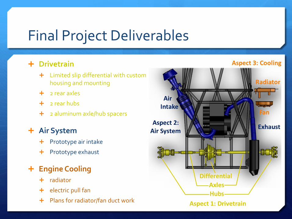
Final Project Deliverables
Drivetrain
Limited slip differential with custom housing and mounting
2 rear axles
2 rear hubs
2 aluminum axle/hub spacers
Air System
Prototype air intake
Prototype exhaust
Engine Cooling
radiator
electric pull fan
Plans for radiator/fan duct work

Final Product Overview

Project Aspect 1: Drivetrain
Transfer engine’s torque through differential, axles, and hubs, to drive wheels

Differential: Final Product
Purchased Honda TRX ATV limited slip differential
Used stock geometry and mounting locations
Manufactured aluminum carrier, uprights, connectors, adapters

Differential: Exploded View
10
12 8 2
2
3 3
1
3
6 5
4
4
9 7
6
6 5 11
11
12
6
7 9
6
1. Honda TRX Limited Slip Differential 2. Differential Housing 3. Housing O-ring Seals 4. Drain Bolt and Seal 5. Hardware Seals 6. Hardware
7. Press Fit Adapter 8. Sprocket 9. Bearing 10. Upright Connections 11. Axle Seals 12. Uprights

Differential: Validation of Metrics
Method Target Metric
Old New Savings
Cost --- <$600 $628 $534 $94.00 (14%)
Weight Scale <7 lbs 7.75 lbs 6.10 lbs 1.65 lbs (21%)
Total Assembly Length
Calipers <10 inches 10.25 inches 4.96 inches 5.29 inches
(51%)
Durability Evaluation No
Leakage present
not fully tested
---

Differential: Testing and Validation
17,700.4
14,225.4
13,275.3
10,325.3
8,850.2
7,375.2
5,900.2
2,950.1
0.1
Upright Stress Test (Bearing Seize)
Initial Filling and Spin Test -More than 25% of total internal volume filled -Spun for 50 turns
Factor of Safety Greater than two

Differential: Path Forward
Final testing will take place during Winter Session 2011
Mimic conditions of 45-minute endurance event
Check for oil leakage
a: Application specific seals
b: O-ring face seals
c: Press fits

Rear Axles: Final Product
(2) 18”Honda TRX ATV axles (Purchased)
Axles cut, 4130 Steel extensions added for length
ATV axles press fit into extension using an acetylene torch for thermal expansion
Welded at four points over the press fits of each axle

Rear Axles: Testing and Validation
Manufacture four test axles, and testing apparatus
Apparatus fixed to platform in the Instron machine in Spencer Laboratory, tension force applies to wire rope, which creates a moment through the lever arm to the test main shaft

Rear Axles: Testing and Validation
Find maximum allowable torque input, failure mode
Torque before failure: 335 ft-lbs (target 168 ft-lbs)
Failure Point – press fit and weld points – axle shaft slips relative to the extension

Rear Axles: Validation of Metrics
Target Metric
Old New (Left
Axle
New (Right Axle)
Savings
Cost <$1,000
as a team $1775.60 $122.47 $122.47 $1,530.66
Weight 6.9 lbs 6.9lbs 6.3 6.9 lbs 0.6lbs
Deflection @ 20 ft-lbs
Less than 1 degree
0.68 degrees
0.61 degrees
0.82 degrees
Insignificant
Allowable Static Torque
168 ft-lbs --- 335 ft-lbs 335 ft-lbs ---

Rear Axles: Path Forward
Can be permanently pressed into differential and rear hubs once hubs are completed

Rear Hubs: Geometric Constraints

Hubs: Final Product
(2) Machined and welded 4130 steel
hubs, 3 part assembly
(2) Machined aluminum wheel
guides
(2) Purchased Taylor Racing Products
64mm wheel bearings
Hardware

FEA Simulation Static Stress Tests: Fatigue Tests: Braking Mode 2 – Failure after 33hrs Cornering – Failure after 28hrs Cost Minimized: $130 (after splining and heat treating) Weight Minimized: 3.1lb each
Resting Acceleration Braking Mode 1 Braking Mode 2 Cornering
Factor of Safety 19.4 5.83 7.37 2.78 2.64
Rear Hubs: Validation

Rear Hubs: Path Forward
Have hubs heat-treated and broached (internally splined) at
RCV Performance over Winter Session 2011
Press lug bolts and wheel bearings in place
Complete upright assemblies
with components from
suspension
Install on car and observe performance

Project Aspect 2: Air System
Allows engine to “breath” via air intake and exhaust
Intake must include 20mm restrictor to limit power
Intake must be inside blue pyramid
Exhaust must maintain engine noise <110dB
Air Intake: Final Product
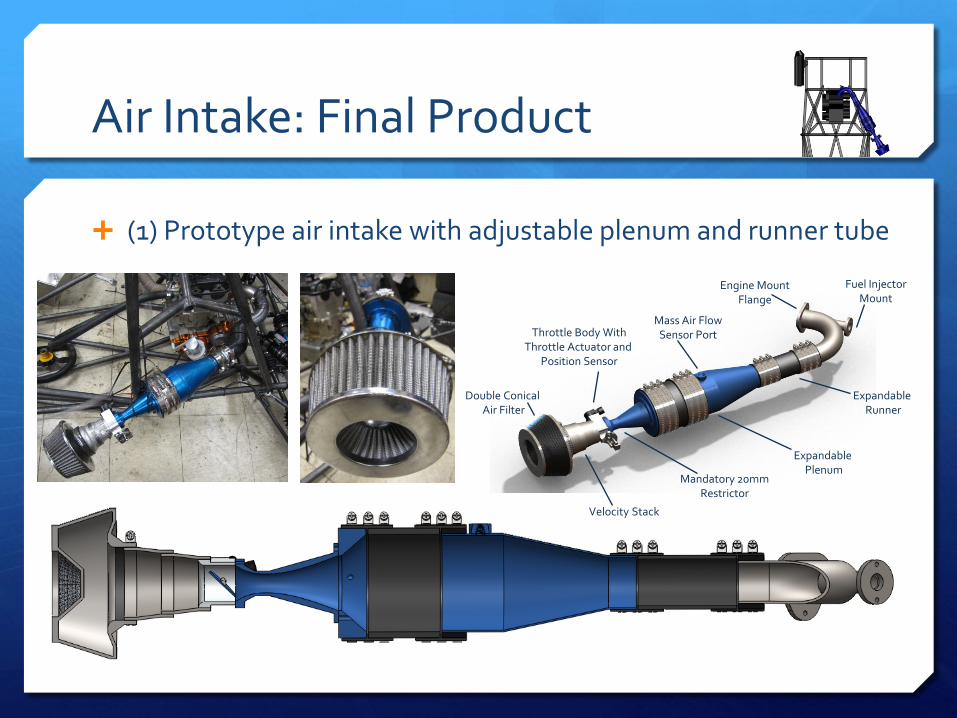
(1) Prototype air intake with adjustable plenum and runner tube
Double Conical Air Filter
Velocity Stack
Mandatory 20mm Restrictor
Throttle Body With Throttle Actuator and
Position Sensor
Expandable Plenum
Mass Air Flow Sensor Port
Expandable Runner
Fuel Injector Mount
Engine Mount Flange

Air Intake: Validation
Post Restrictor Component Order
Fuel Injector Position
Minimized Cost: $110
09-10 Car New Prototype
Air Filtration Area 17.69in2 43.24in2
Plenum Volume 2.5*511cc [2.5*511cc:5*511cc]
Runner Length 13.3in [11.3in:17.3in]

Air Intake: Path Forward
Utilize adjustable intake for tuning/performance tests on dyno during winter session 2011 examining Horsepower and Torque versus RPM to find optimum plenum volume and runner length.
Use CFD software to optimize design
Manufacture final air intake
Install on car and observe performance

Exhaust: Final Product
Expandable Exhaust Prototype
Stainless Steel Expandable Main Tube (1-5/8” OD)
Expandable from 27” – 35” (Total Exhaust Length)
Uses copper insulating wrap to reduce heat in the engine bay.
FMF Q4 muffler

Exhaust: Final Product
Noise – Function of airflow out of exhaust valve, length of primary tube, outer diameter and thickness of the tube, number of bends, size and efficiency of the muffler
All materials for prototype were given from FSAE
Exhaust: Future Testing and Validation
Noise Test:
Test for exhaust noise following the guidelines of the FSAE noise test, at optimal air intake size and proper engine tuning
Noise readings taken in decibels at 10,500 RPM
110 dB constraint
Previous Exhaust – 28” primary length, passed noise test last year at competition
Expandable Exhaust – 27” – 35” primary length
Compromise between noise and power based on length of primary tube

Exhaust: Path Forward
Increase muffler sound dampening qualities - repack muffler gauze
Perform noise tests at varying main tube lengths once the final air intake is manufactured and the engine is properly tuned

Project Aspect 3: Cooling
Must use plain water as engine coolant

Engine Cooling: Final Product
2004-05 Yamaha YFZ450 radiator
Derale Cooling Products 7” Tornado Push/Pull Fan
4 feet of 1” OD rubber heater hose
Pressure relief valve on engine
Radiator bolted to right side of chassis

Engine Cooling: Testing
2009-10 car
Let car reach operating temperature
Inlet/outlet temperature readings were taken from radiator
Readings taken at idle (3,500 RPM), half throttle (6,500 RPM), and full throttle (10,500 RPM)
Performed with 2009-10 electric fan 0.375 inches behind radiator
Inlet Port
Outlet Port

Engine Cooling: Validation of Metrics
Target Metric Old System New System Savings
Cost <$15 --- $9 ---
Total Weight <5 lbs 4.75 lbs 4.25 lbs 0.5 lbs (12%)
Volume Space < 1,872 cubic inches
(8”x13”x18”)
500 cubic inches
(10”x10”x5”)
1,465 cubic inches
(7.4”x11”x18”) none
Heat Dissipated >17,000 W 16,861 W 20,753 W 3,892 W (23%)
Fan Amperage Draw <5 A --- 4.8A ---

Engine Cooling: Path Forward
Detailed ducting designs are available for composite material manufacturing over Winter Session 2011

Special Thanks
We would like to give a special thanks to the following people and businesses:
Ernie Martelli, Martelli’s Metal Fabrication—Ivyland, PA
Adam Kinzey and Doug Brunner— UD fuel cell laboratory
Steve Beard—UD ME student machine shop
PowerSports East—Bear, DE
RCV Performance—Loves Park, IL
CMX—Ivyland, PA
Dale Cherry, Injection Connection—Horsham, PA

Thank you for attending our presentation. What questions can we answer?

Applicable 2011 FSAE Rules
Must use a 4-stroke engine, up to 610 cc piston displacement
Air intake must lie within space defined by top roll hoop and outside edges of tires
A maximum 20-mm restrictor must be placed inside air intake between throttle and engine
Must use water as engine coolant
Exhaust components must be less than 45 cm behind rear axles and less than 60 cm above the ground
Maximum permitted exhaust level is 110 dB

Starting Point: 2009-10 UD SAE Car
Single Cylinder, 511-cc Yamaha YFZ450 ATV engine, rear mounted, chain drive
High Power-to-Weight Ratio