Seminar on Scalability of Distributed Systems. Distributed Rendering with 3DSMAX.
Upload
hillary-wattsCategory
view
36download
0description
Seminar 1Surface Rendering, Decimation
Presented By Sonali Barua
Date:10/31/2005
Marching Cubes
Algorithm to create Triangle Models of 3D Medical Data
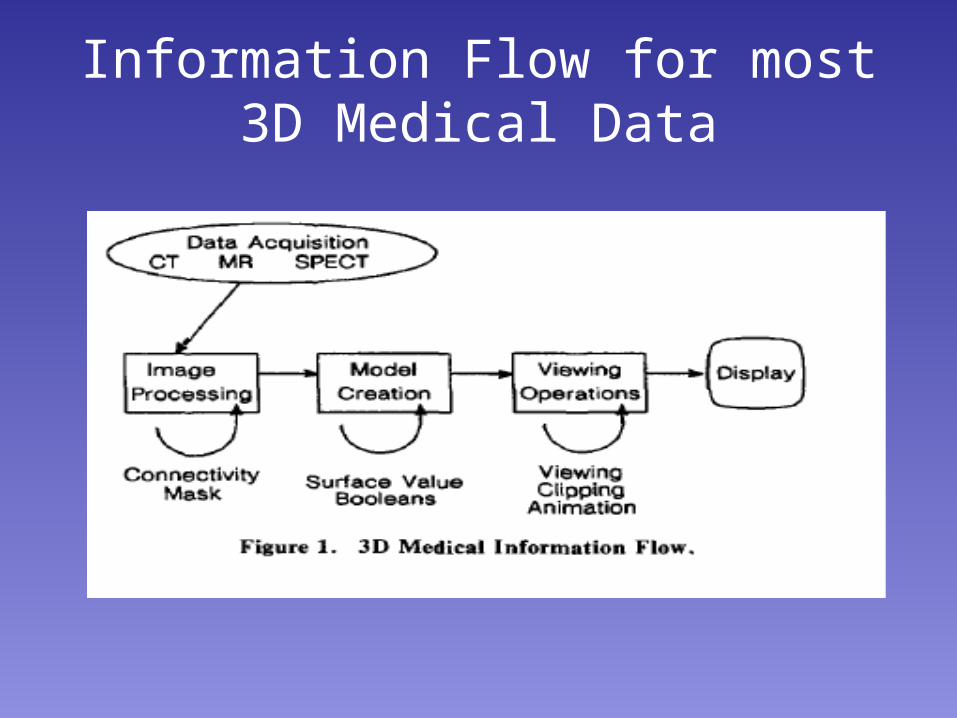
Information Flow for most 3D Medical Data
Former Algorithms and Drawbacks
• Surface Contours, Cuberilles (voxels), Octree, ray casting, shadow graph of density volume
• Didn’t work as they threw away useful information in the original Data such as inter slice connectivity and some algorithms relied on Motion to give a 3D effect
Marching Cubes
• Retains the Original 3D Data
• Can be Displayed using standard rendering Algorithms.
• Uses Divide and Conquer Techniques to calculate the surface in a logical cube created from 8 pixels, four each from adjacent slices.
Approach
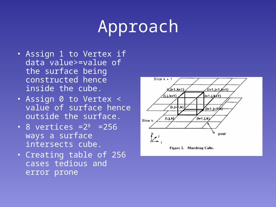
• Assign 1 to Vertex if data value>=value of the surface being constructed hence inside the cube.
• Assign 0 to Vertex < value of surface hence outside the surface.
• 8 vertices =28 =256 ways a surface intersects cube.
• Creating table of 256 cases tedious and error prone
Alternate way
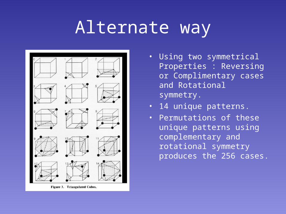
• Using two symmetrical Properties : Reversing or Complimentary cases and Rotational symmetry.
• 14 unique patterns.• Permutations of these unique
patterns using complementary and rotational symmetry produces the 256 cases.
Indexes
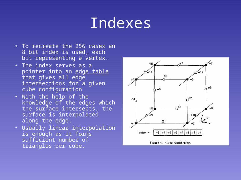
• To recreate the 256 cases an 8 bit index is used, each bit representing a vertex.
• The index serves as a pointer into an edge table that gives all edge intersections for a given cube configuration
• With the help of the knowledge of the edges which the surface intersects, the surface is interpolated along the edge.
• Usually linear interpolation is enough as it forms sufficient number of triangles per cube.
Steps in Marching Cubes
• Four Slices of Data are read into Memory• Scan two slices Create a cube using four neighbors from
each of the slices.• An index of the Cube is Calculated by Comparing density
values with user specified surface constants.• Using the Index, list of edges is looked up from the table.• Linear interpolation is used to calculate the surface edge
intersection using the densities of the vertices.• Unit Normal at each vertex of the cube is calculated. The
Normal is interpolated to each triangle vertex.• The triangle vertices and the vertex Normal are the
outputs which is consequently used for Gourand shading.
Calculating the Gradient Normal of each triangle vertex
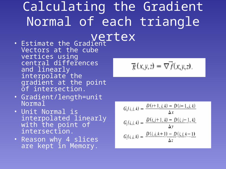
• Estimate the Gradient Vectors at the cube vertices using central differences and linearly interpolate the gradient at the point of intersection.
• Gradient/length=unit Normal
• Unit Normal is interpolated linearly with the point of intersection.
• Reason why 4 slices are kept in Memory.
Enhancements
• Efficiency.
• By getting 9 edges from previous slices and calculating only 3 edges.
• Save only previous line and pixel intersections.
• Reduction of Slice resolution using averaging , though it causes loss of data.
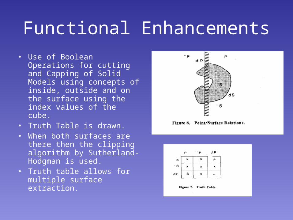
Functional Enhancements
• Use of Boolean Operations for cutting and Capping of Solid Models using concepts of inside, outside and on the surface using the index values of the cube.
• Truth Table is drawn.• When both surfaces are there
then the clipping algorithm by Sutherland- Hodgman is used.
• Truth table allows for multiple surface extraction.
Implementation
• C language
• Sun workstations using UNIX, VAX under VMS and IBM 3081 under IX/370
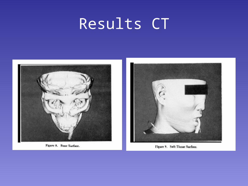
Results CT
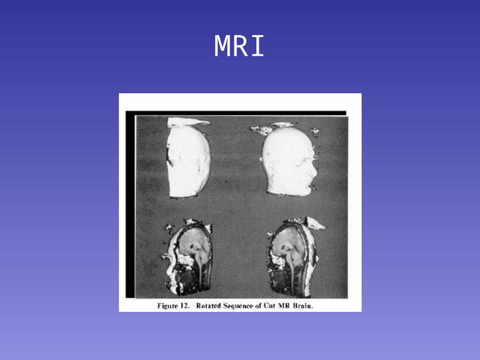
MRI
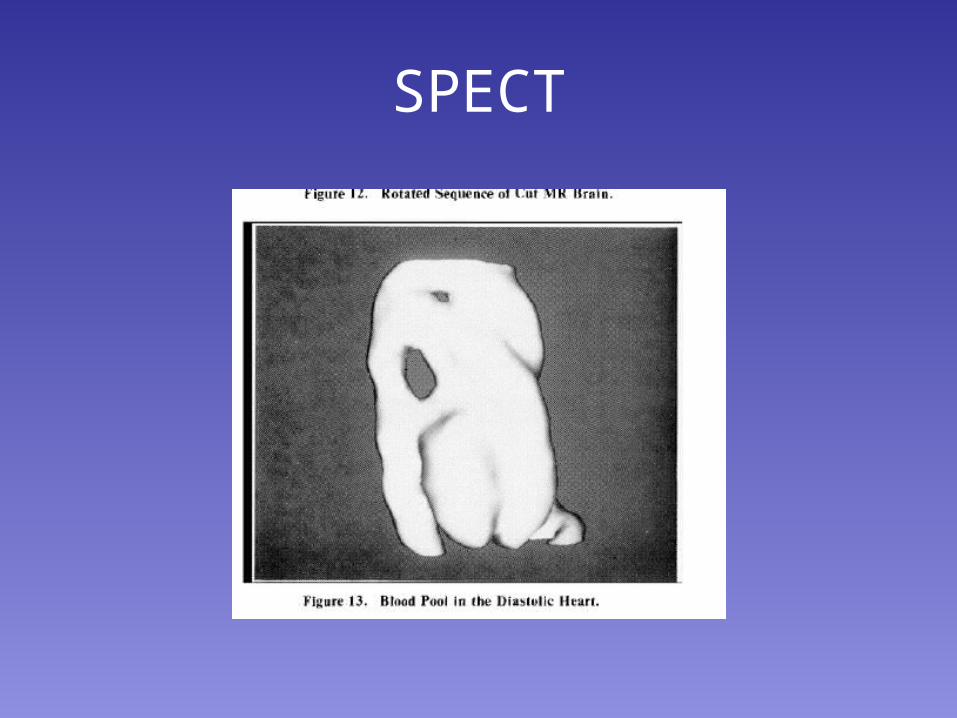
SPECT

Questions
?????
Decimation of Triangle Meshes
Algorithm to reduce the number of triangles rendered.
Reason for the Algorithm
• Rendering speeds and memory requirements are proportional to the number of polygons.
• Surface construction Algorithms such as Marching cubes creates large number of triangles to render.
Decimation
• Goal: Reduce the total number of Triangles while still retaining most of the important features
• Applies to Discrete Modeling.• Approaches can be either Adaptive or Filter based for
synthesizing objects• Adaptive: Produces more primitives in selected Areas.• Filter based: Starts with large number of samples and
replaces samples to reduce model size.
Reduced Mesh Requirements
• Must preserve original topology of mesh including non-manifold forms.
• Good Geometric Approximation to the original Mesh.
• Hence, New vertices should not be created.
The Simple Algorithm
• For each pass and each vertex• Characterize the local vertex geometry and
topology• Evaluate the decimation criteria• Triangulate the resulting hole
• Multiple passes are made over all vertices with adjustments in the decimation criteria until a termination criteria is met.
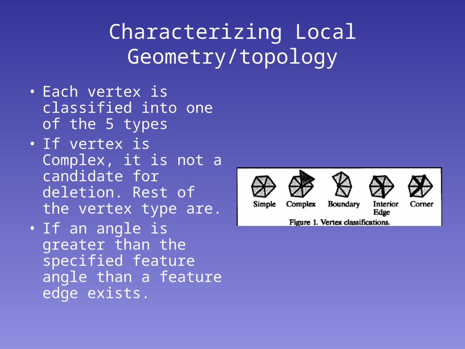
Characterizing Local Geometry/topology
• Each vertex is classified into one of the 5 types
• If vertex is Complex, it is not a candidate for deletion. Rest of the vertex type are.
• If an angle is greater than the specified feature angle than a feature edge exists.
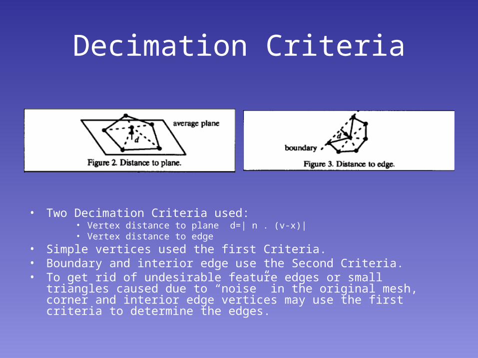
Decimation Criteria
• Two Decimation Criteria used:• Vertex distance to plane d=| n . (v-x)|• Vertex distance to edge
• Simple vertices used the first Criteria.• Boundary and interior edge use the Second Criteria.• To get rid of undesirable feature edges or small triangles caused due to
“noise” in the original mesh, corner and interior edge vertices may use the first criteria to determine the edges.
Triangulation
• Deletion of vertex causes one or two loops.• In each loop a triangulation must be created
such that they are non-intersecting and non-degenerate.
• Two Important Characteristics are used:• If loop cannot be triangulated, vertex is not deleted.• Due to the star shaped nature of each loop, recursive
splitting will be effective.
• Upon completion of triangulation, original vertex and it’s triangles are deleted.
Implementation
• It is used as a filter in LYMB/VISAGE visualization environment.
• Algorithm repeated till a specified decimation threshold is met.
• Decimation is controlled by slowly adjusting the distance and feature angle criterion
• Sometimes Number of iteration is limited• Triangulation aspect ratio is also modified.
Data Structures
• Uses a vertex –triangle ring hierarchy structure
• Contains hierarchical pointers from vertex up to triangles using the vertex and pointers from triangles down to vertices.
• three lists:• List of Vertex Coordinates.• List of Triangle definition.• List of lists using the each vertex.
Triangulation
• Recursive loop splitting Algorithm• Each loop divided into 2 halves along a Split
line.• Split line = a line defined by 2 non-neighboring
vertices in loop• Each new loop is divided till there is only 3
vertices remaining• A loop of 3 vertices forms a triangle that is
added to the Mesh.
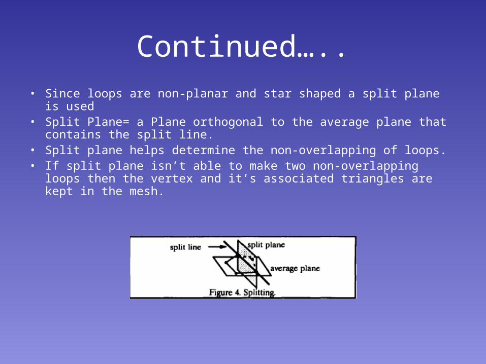
Continued…..
• Since loops are non-planar and star shaped a split plane is used• Split Plane= a Plane orthogonal to the average plane that contains
the split line.• Split plane helps determine the non-overlapping of loops.• If split plane isn’t able to make two non-overlapping loops then the
vertex and it’s associated triangles are kept in the mesh.
Aspect Ratio
• Each loop can be split more than one way, so best splitting plane is used.
• To get this a criteria of aspect ratio is used• Aspect ratio= (min distance of the loop vertices
to the split plane)/length of the split line.• Best Split plane=max (aspect ratio). Can be
made to be greater than some specified aspect ratio.
Special Cases
• Closed tetrahedron, Tunnels.
• Remove a vertex to resolve the issue.
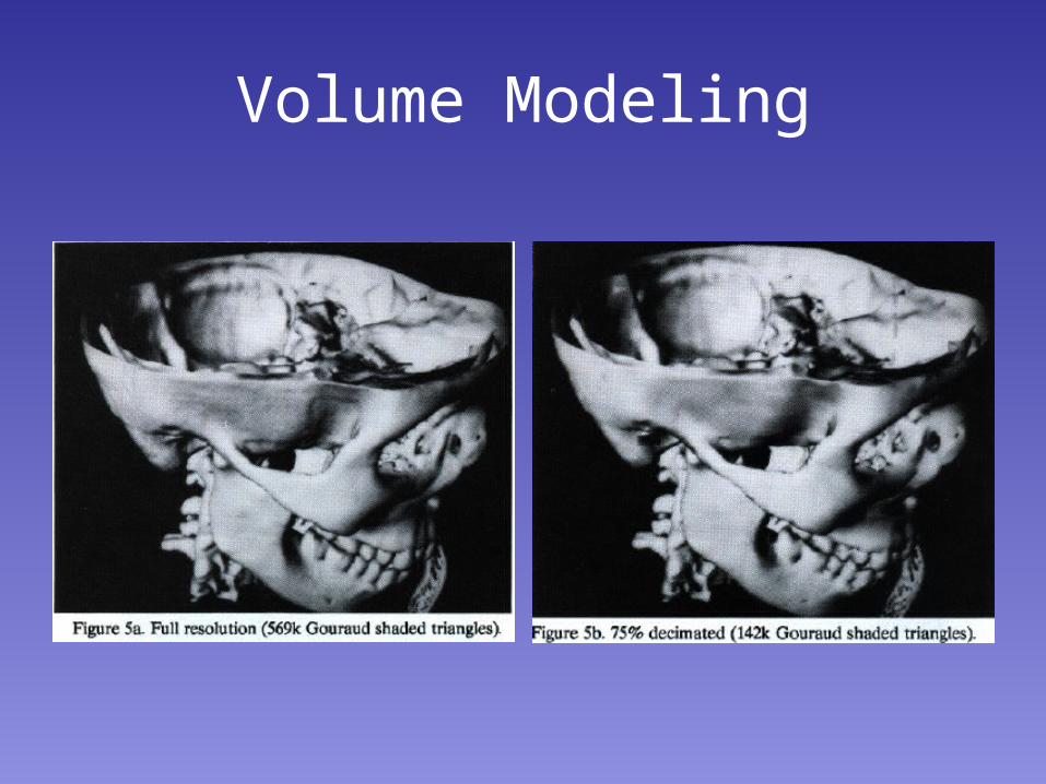
Volume Modeling
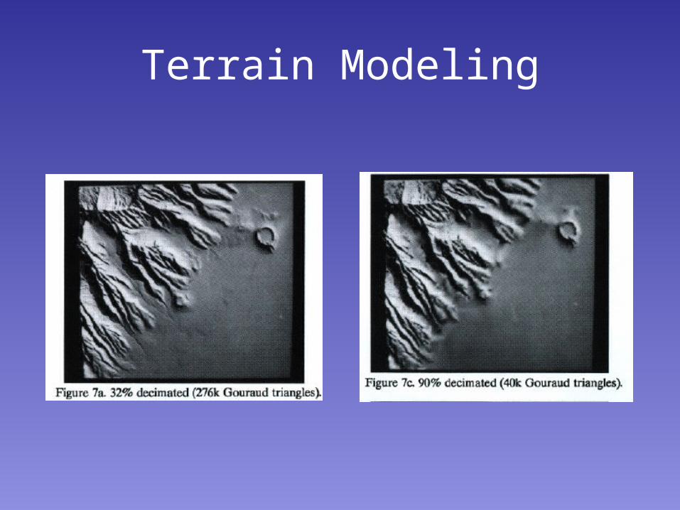
Terrain Modeling

Questions???
Thank you