Semi-Analytical Method Based on Magnetic Equivalent ...
12
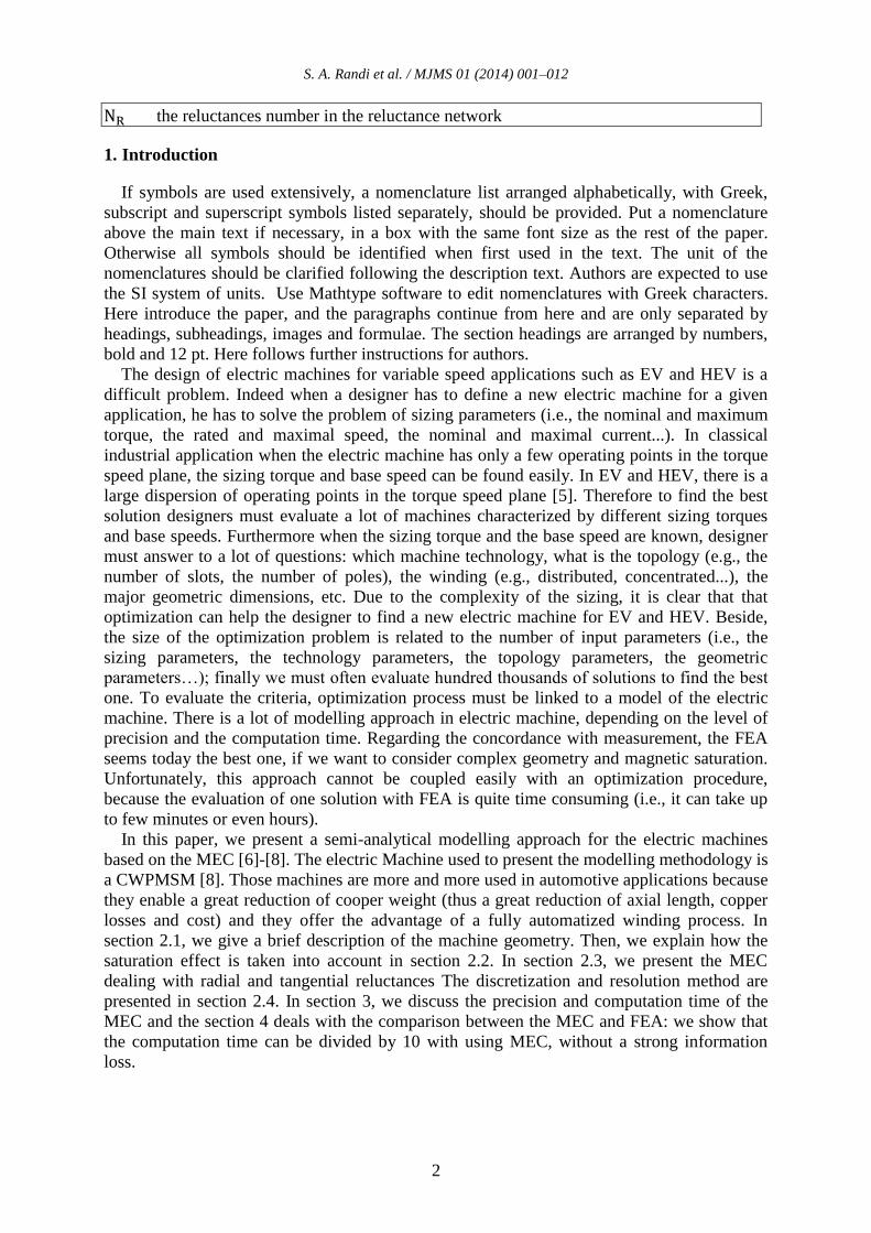
Mediterranean Journal of Modeling and Simulation MJMS 01 (2014) 001–012 Semi-Analytical Method Based on Magnetic Equivalent Circuit for Synchronous Permanent-Magnet Machines in EV and HEV Applications S.A. Randi a , R. Benlamine a , F. Dubas b , and C. Espanet b a Renault SAS, 78288 Guyancourt, France b FEMTO-ST Institute, UFC, ENERGIE Department, UMR 6174 CNRS, 90010 Belfort, France Abstract Concentrated Winding Permanent-Magnet (PM) Synchronous Machines (CWPMSM) are more and more used to drive electromechanical systems working in variable speed mode, such as Electric Vehicle (EV) and Hybrid Electric Vehicle (HEV) applications. In order to design and optimize these machines, the authors propose a semi-analytical method based on magnetic equivalent circuit (MEC). The studied structure, 12-slots/8-poles CWPMSM, is an internal rotor topology with surface mounted PMs having radial magnetization. We compare the results obtained with finite-element analysis (FEA) with those given by the MEC. In this paper both precision and time computation are evaluated in order to analyse the possible implementation of the model in an optimal design tool. Keywords: Concentrated winding, Permanent-magnet, Synchronous machines, Magnetic equivalent circuit, Finite-element analysis. Nomenclature the magnetic field calculated by Marrocco interpolation the flux density reduced value of the flux density B s ( ) the vacuum permeability the Marrocco interpolation coefficients (i=1,…4) radial reluctances tangential reluctances the reluctances matrix S the loop matrix F the sources vector the loop fluxes vector the reluctance fluxes vector the reluctance surface vector the magneto-motive force provided by PM the magneto-motive force provided by a coil the thickness of the PM the number of turns per coil the phase current the loops number in the reluctance network
Transcript of Semi-Analytical Method Based on Magnetic Equivalent ...
Mediterranean Journal of
Modeling and Simulation
MJMS 01 (2014) 001–012
Semi-Analytical Method Based on Magnetic Equivalent
Circuit for Synchronous Permanent-Magnet Machines
in EV and HEV Applications
S.A. Randia, R. Benlamine
a, F. Dubas
b, and C. Espanet
b
a Renault SAS, 78288 Guyancourt, France
b FEMTO-ST Institute, UFC, ENERGIE Department, UMR 6174 CNRS, 90010 Belfort, France
Abstract
Concentrated Winding Permanent-Magnet (PM) Synchronous Machines (CWPMSM) are more and
more used to drive electromechanical systems working in variable speed mode, such as Electric
Vehicle (EV) and Hybrid Electric Vehicle (HEV) applications. In order to design and optimize these
machines, the authors propose a semi-analytical method based on magnetic equivalent circuit (MEC).
The studied structure, 12-slots/8-poles CWPMSM, is an internal rotor topology with surface mounted
PMs having radial magnetization. We compare the results obtained with finite-element analysis (FEA)
with those given by the MEC. In this paper both precision and time computation are evaluated in order
to analyse the possible implementation of the model in an optimal design tool.
Keywords: Concentrated winding, Permanent-magnet, Synchronous machines, Magnetic equivalent circuit,
Finite-element analysis.
Nomenclature
the magnetic field calculated by Marrocco interpolation
the flux density
reduced value of the flux density Bs (
)
the vacuum permeability
the Marrocco interpolation coefficients (i=1,…4)
radial reluctances
tangential reluctances
the reluctances matrix
S the loop matrix
F the sources vector
the loop fluxes vector
the reluctance fluxes vector
the reluctance surface vector
the magneto-motive force provided by PM
the magneto-motive force provided by a coil
the thickness of the PM
the number of turns per coil
the phase current
the loops number in the reluctance network
S. A. Randi et al. / MJMS 01 (2014) 001–012
2
the reluctances number in the reluctance network
1. Introduction
If symbols are used extensively, a nomenclature list arranged alphabetically, with Greek,
subscript and superscript symbols listed separately, should be provided. Put a nomenclature
above the main text if necessary, in a box with the same font size as the rest of the paper.
Otherwise all symbols should be identified when first used in the text. The unit of the
nomenclatures should be clarified following the description text. Authors are expected to use
the SI system of units. Use Mathtype software to edit nomenclatures with Greek characters.
Here introduce the paper, and the paragraphs continue from here and are only separated by
headings, subheadings, images and formulae. The section headings are arranged by numbers,
bold and 12 pt. Here follows further instructions for authors.
The design of electric machines for variable speed applications such as EV and HEV is a
difficult problem. Indeed when a designer has to define a new electric machine for a given
application, he has to solve the problem of sizing parameters (i.e., the nominal and maximum
torque, the rated and maximal speed, the nominal and maximal current...). In classical
industrial application when the electric machine has only a few operating points in the torque
speed plane, the sizing torque and base speed can be found easily. In EV and HEV, there is a
large dispersion of operating points in the torque speed plane [5]. Therefore to find the best
solution designers must evaluate a lot of machines characterized by different sizing torques
and base speeds. Furthermore when the sizing torque and the base speed are known, designer
must answer to a lot of questions: which machine technology, what is the topology (e.g., the
number of slots, the number of poles), the winding (e.g., distributed, concentrated...), the
major geometric dimensions, etc. Due to the complexity of the sizing, it is clear that that
optimization can help the designer to find a new electric machine for EV and HEV. Beside,
the size of the optimization problem is related to the number of input parameters (i.e., the
sizing parameters, the technology parameters, the topology parameters, the geometric
parameters…); finally we must often evaluate hundred thousands of solutions to find the best
one. To evaluate the criteria, optimization process must be linked to a model of the electric
machine. There is a lot of modelling approach in electric machine, depending on the level of
precision and the computation time. Regarding the concordance with measurement, the FEA
seems today the best one, if we want to consider complex geometry and magnetic saturation.
Unfortunately, this approach cannot be coupled easily with an optimization procedure,
because the evaluation of one solution with FEA is quite time consuming (i.e., it can take up
to few minutes or even hours).
In this paper, we present a semi-analytical modelling approach for the electric machines
based on the MEC [6]-[8]. The electric Machine used to present the modelling methodology is
a CWPMSM [8]. Those machines are more and more used in automotive applications because
they enable a great reduction of cooper weight (thus a great reduction of axial length, copper
losses and cost) and they offer the advantage of a fully automatized winding process. In
section 2.1, we give a brief description of the machine geometry. Then, we explain how the
saturation effect is taken into account in section 2.2. In section 2.3, we present the MEC
dealing with radial and tangential reluctances The discretization and resolution method are
presented in section 2.4. In section 3, we discuss the precision and computation time of the
MEC and the section 4 deals with the comparison between the MEC and FEA: we show that
the computation time can be divided by 10 with using MEC, without a strong information
loss.
S. A. Randi et al. / MJMS 01 (2014) 001–012
3
2. Semi-Analytical Modelling via MEC
2.1. Electrical Machine Description and Assumptions
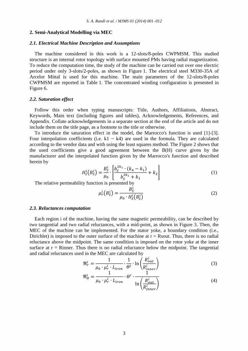
The machine considered in this work is a 12-slots/8-poles CWPMSM. This studied
structure is an internal rotor topology with surface mounted PMs having radial magnetization.
To reduce the computation time, the study of the machine can be carried out over one electric
period under only 3-slots/2-poles, as shown in Figure 1. The electrical steel M330-35A of
Arcelor Mittal is used for this machine. The main parameters of the 12-slots/8-poles
CWPMSM are reported in Table 1. The concentrated winding configuration is presented in
Figure 6.
2.2. Saturation effect
Follow this order when typing manuscripts: Title, Authors, Affiliations, Abstract,
Keywords, Main text (including figures and tables), Acknowledgements, References, and
Appendix. Collate acknowledgements in a separate section at the end of the article and do not
include them on the title page, as a footnote to the title or otherwise.
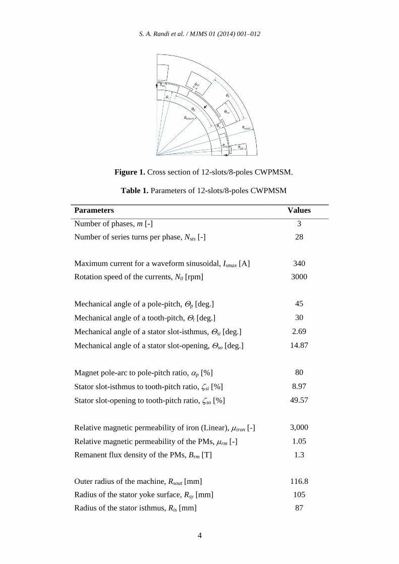
To introduce the saturation effect in the model, the Marrocco's function is used [1]-[3].
Four interpolation coefficients (i.e. k1 ~ k4) are used in the formula. They are calculated
according to the vendor data and with using the least squares method. The Figure 2 shows that
the used coefficients give a good agreement between the B(H) curve given by the
manufacturer and the interpolated function given by the Marrocco's function and described
herein by
(1)
The relative permeability function is presented by
(2)
2.3. Reluctances computation
Each region i of the machine, having the same magnetic permeability, can be described by
two tangential and two radial reluctances, with a mid-point, as shown in Figure 3. Then, the
MEC of the machine can be implemented. For the stator yoke, a boundary condition (i.e.,
Dirichlet) is imposed to the outer surface of the machine at r = Rsout. Thus, there is no radial
reluctance above the midpoint. The same condition is imposed on the rotor yoke at the inner
surface at r = Rinner. Thus there is no radial reluctance below the midpoint. The tangential
and radial reluctances used in the MEC are calculated by
(3)
(4)
S. A. Randi et al. / MJMS 01 (2014) 001–012
4
Figure 1. Cross section of 12-slots/8-poles CWPMSM.
Table 1. Parameters of 12-slots/8-poles CWPMSM
Parameters Values
Number of phases, m [-] 3
Number of series turns per phase, Nsts [-] 28
Maximum current for a waveform sinusoidal, Ismax [A] 340
Rotation speed of the currents, N0 [rpm] 3000
Mechanical angle of a pole-pitch, p [deg.] 45
Mechanical angle of a tooth-pitch, t [deg.] 30
Mechanical angle of a stator slot-isthmus, si [deg.] 2.69
Mechanical angle of a stator slot-opening, so [deg.] 14.87
Magnet pole-arc to pole-pitch ratio, p [%] 80
Stator slot-isthmus to tooth-pitch ratio, si [%] 8.97
Stator slot-opening to tooth-pitch ratio, so [%] 49.57
Relative magnetic permeability of iron (Linear), iron [-] 3,000
Relative magnetic permeability of the PMs, rm [-] 1.05
Remanent flux density of the PMs, Brm [T] 1.3
Outer radius of the machine, Rsout [mm] 116.8
Radius of the stator yoke surface, Rsy [mm] 105
Radius of the stator isthmus, Ris [mm] 87
S. A. Randi et al. / MJMS 01 (2014) 001–012
5
Radius of the stator surface, Rs [mm] 85
Radius of the PMs surface, Rm [mm] 83.8
Radius of the rotor yoke surface, Rr [mm] 75.8
Inner radius of the machine, Rinner [mm] 64
Machine axial length, Liron [mm] 100
Figure 2. B(H) curves given by the manufacturer
and Marrocco interpolation.
Reluctances for each region i
Boundary Condition at Boundary Condition at
Rsout Rinner
Figure 3. Reluctance for each region i of the machine and boundary conditions
S. A. Randi et al. / MJMS 01 (2014) 001–012
6
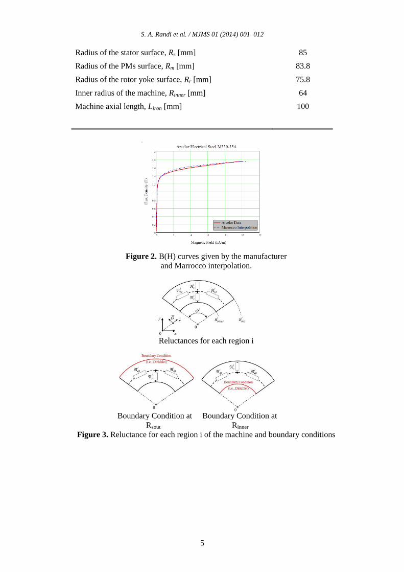
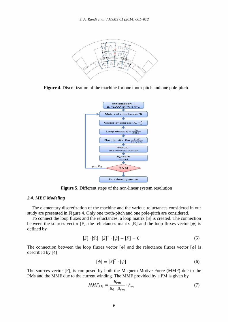
Figure 4. Discretization of the machine for one tooth-pitch and one pole-pitch.
Figure 5. Different steps of the non-linear system resolution
2.4. MEC Modeling
The elementary discretization of the machine and the various reluctances considered in our
study are presented in Figure 4. Only one tooth-pitch and one pole-pitch are considered.
To connect the loop fluxes and the reluctances, a loop matrix [S] is created. The connection
between the sources vector [F], the reluctances matrix [R] and the loop fluxes vector [ ] is
defined by
(5)
The connection between the loop fluxes vector [ ] and the reluctance fluxes vector [ ] is
described by [4]
(6)
The sources vector [F], is composed by both the Magneto-Motive Force (MMF) due to the
PMs and the MMF due to the current winding. The MMF provided by a PM is given by
(7)
S. A. Randi et al. / MJMS 01 (2014) 001–012
7
while the MMF provided by one coil, containing turns and fed by a current , is expressed
by
(8)
The reluctances matrix is a diagonal matrix [NRXNR], where the diagonal is formed
by the different reluctances. The loop fluxes matrix is a vector [NLX1] formed by the
different loop fluxes. The sources matrix [F] has the same dimensions as the matrix . The
loop matrix [S] is constituted by NR columns and NL lines ([NLXNR]).
The non-linear system taking into account the saturation effect is solved iteratively. The
vector [F] is divided into N parts (equal or not). Then, (5) and (6) are solved in order to obtain
the reluctance fluxes vector . Thus the reluctance flux density vector [B], is calculated
using the vector and the reluctance surfaces vector [SR]. The new magnetic permeability
can be calculated using (1) and (2), and the vector [B] is added to that obtained during the
previous iteration. The different resolution steps are described in Figure 5.
The magnetic permeability is considered as constant in a range of a MMF equal to [F]/N for
each iteration. Higher is the number of discretization N, higher the accuracy is.
3.1. Numerical Tool
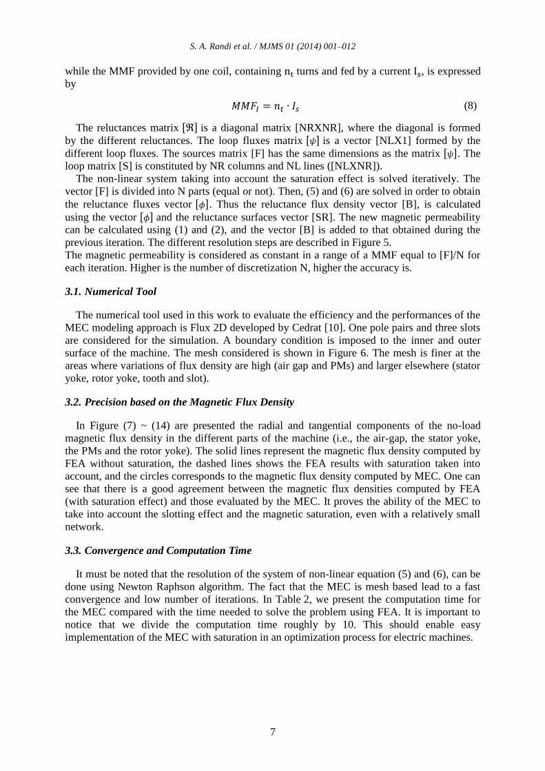
The numerical tool used in this work to evaluate the efficiency and the performances of the
MEC modeling approach is Flux 2D developed by Cedrat [10]. One pole pairs and three slots
are considered for the simulation. A boundary condition is imposed to the inner and outer
surface of the machine. The mesh considered is shown in Figure 6. The mesh is finer at the
areas where variations of flux density are high (air gap and PMs) and larger elsewhere (stator
yoke, rotor yoke, tooth and slot).
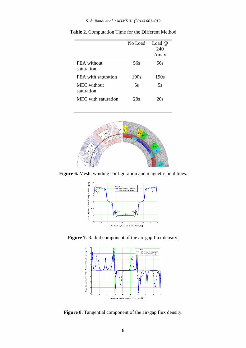
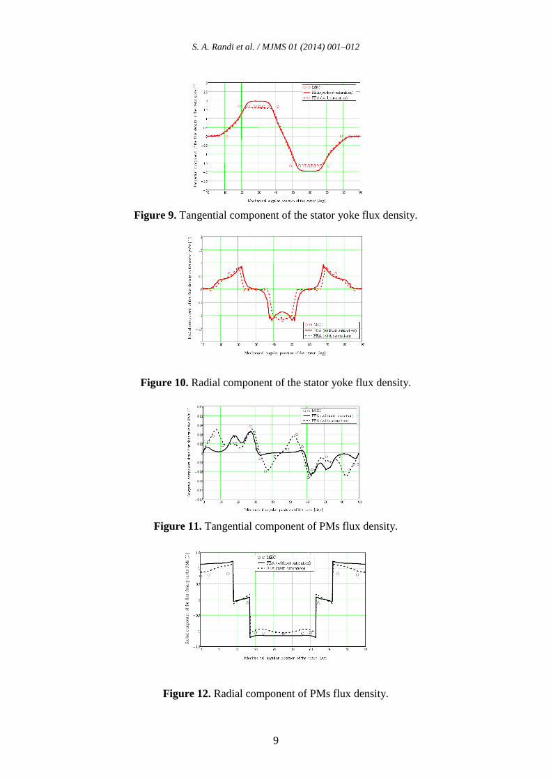
3.2. Precision based on the Magnetic Flux Density
In Figure (7) ~ (14) are presented the radial and tangential components of the no-load
magnetic flux density in the different parts of the machine (i.e., the air-gap, the stator yoke,
the PMs and the rotor yoke). The solid lines represent the magnetic flux density computed by
FEA without saturation, the dashed lines shows the FEA results with saturation taken into
account, and the circles corresponds to the magnetic flux density computed by MEC. One can
see that there is a good agreement between the magnetic flux densities computed by FEA
(with saturation effect) and those evaluated by the MEC. It proves the ability of the MEC to
take into account the slotting effect and the magnetic saturation, even with a relatively small
network.
3.3. Convergence and Computation Time
It must be noted that the resolution of the system of non-linear equation (5) and (6), can be
done using Newton Raphson algorithm. The fact that the MEC is mesh based lead to a fast
convergence and low number of iterations. In Table 2, we present the computation time for
the MEC compared with the time needed to solve the problem using FEA. It is important to
notice that we divide the computation time roughly by 10. This should enable easy
implementation of the MEC with saturation in an optimization process for electric machines.
S. A. Randi et al. / MJMS 01 (2014) 001–012
8
Table 2. Computation Time for the Different Method
No Load Load @
240
Amax
FEA without
saturation
56s 56s
FEA with saturation 190s 190s
MEC without
saturation
5s 5s
MEC with saturation 20s 20s
Figure 6. Mesh, winding configuration and magnetic field lines.
Figure 7. Radial component of the air-gap flux density.
Figure 8. Tangential component of the air-gap flux density.
S. A. Randi et al. / MJMS 01 (2014) 001–012
9
Figure 9. Tangential component of the stator yoke flux density.
Figure 10. Radial component of the stator yoke flux density.
Figure 11. Tangential component of PMs flux density.
Figure 12. Radial component of PMs flux density.
S. A. Randi et al. / MJMS 01 (2014) 001–012
10
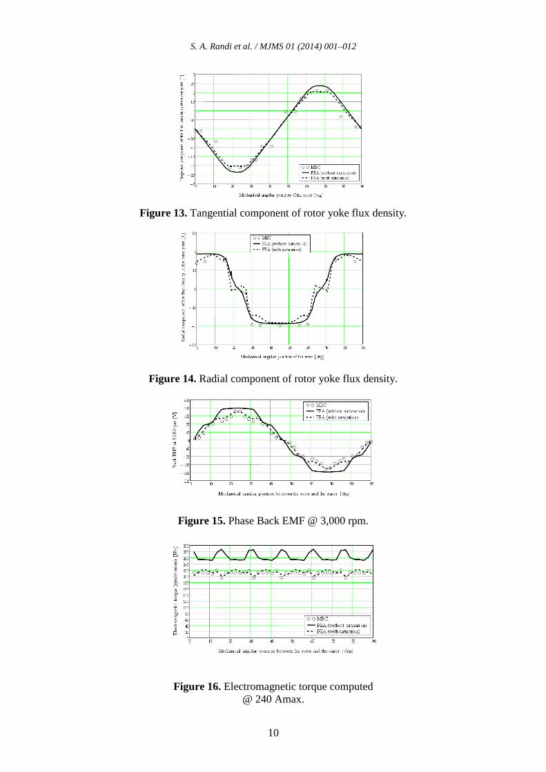
Figure 13. Tangential component of rotor yoke flux density.
Figure 14. Radial component of rotor yoke flux density.
Figure 15. Phase Back EMF @ 3,000 rpm.
Figure 16. Electromagnetic torque computed
@ 240 Amax.
S. A. Randi et al. / MJMS 01 (2014) 001–012
11
4. Comparison Based on Integral Quantities – Back-EMF and Electromagnetic Torque
4.1. Back-EMF in phase-A
In Figure 15 we represent the Back-EMF in phase-A at 3,000 rpm computed by the three
different methods: the solid line represents the Back-EMF computed by FEA assuming a
linear characteristic of the iron, the dashed line corresponds to the FEA taken into account
saturation, and circles represent the points obtained with the MEC. One can see that also for
integral value of the machine, there is a good agreement between the results given by FEA
and those calculated with MEC.
4.2. Electromagnetic Torque
The electromagnetic torque is an important output of our modeling. Indeed this value must
be computed with a very good accuracy, since the torque produced by the drive should match
with the technical specifications. In Figure 16 we depict three torque curves. The solid line
shows the torque computed by FEA in linear condition, the dashed line shows the torque
computed by FEA assuming the real B(H) characteristic and the circles corresponds to the
points of torque computed by the MEC where the saturation effect is taken into account. It
must be noted that the average torque when the saturation is taken into account is lower than
the torque when we assume a linear iron steel. One can see also that the MEC modeling give
us a quite satisfying correspondence in term of torque computation.
5. Conclusion
In this paper, we present a semi-analytical modeling approach suitable for the design of
electric machine used in EV and HEV applications. The method presented is based on the
MEC. The parametric modeling of a new electric machine may take time for the designer.
Therefore once the model is built, the parametric study and machine optimization should be
achieved easily. To illustrate the efficiency of the method, a 12-slots/8-poles cconcentrated
winding PM synchronous machines is used as an example. The comparison between local
quantities computed by FEA and those obtained by MEC shows a good agreement, and
obviously the integral quantities (i.e., the back-EMF, the electromagnetic torque) correspond
too. The main advantage of the MEC is that we can get a precision comparable to what we
can obtain by FEA, and with computation time divide by 10. For this reason it should be easy
to implement the MEC models in an optimization tool.
6. References
[1] A. Marrocco, "Analyse numérique de problèmes d’électrotechnique," Ann. Sc. Math.
Québec, 1977, vol 1, No 2, pp 271-296
[2] F. Hecht, A. Marrocco, F. Piriou, and A. Razek, "Modélisation de systèmes
électrotechniques par couplage des équations électriques et magnétiques," Rev. Phys.
Appl. 1990, pp 649-659
[3] F. Dubas, "Conception d’un moteur rapide à aimants permanents pour l’entraînement de
compresseurs de piles à combustibles," PhD Thesis, Université de Franche-Comté
(France), December 2006
[4] A. Delale, L. Albert, L. Gerbaud, and F. Wurtz, "Automatic Generation of Sizing Models
for the Optimization of Electromagnetic Devices Using Reluctance Networks," IEEE
Trans. on Magn., vol. 40, no. 2, March 2004
S. A. Randi et al. / MJMS 01 (2014) 001–012
12
[5] S.A. Randi, "Conception systémique de chaînes de traction synchrones pour véhicules
électriques," PhD Thesis, INP Toulouse (France), April 2003
[6] V. Ostovic, "A Simplified Approach to Magnetic Equivalent Circuit Modeling of
Induction Machines," IEEE Trans. Ind. Appl., vol. 24, no. 2, pp. 308-316,
March/April 1988
[7] V. Ostovic, "A Novel Method for Evaluation of Transient States in Saturated Electric
Machines," IEEE Trans. Ind. Appl., vol. 25, no. 1, pp. 96-100, January/February 1989
[8] C.B. Rasmussen, and E. Ritchie, "Magnetic Equivalent Circuit Method For Designing
Permanent Magnet Motors," in Proc. ICEM, Vigo, Spain, Sept. 10-12, 1996
[9] J.K. Tangudu, T.M. Jahns, A. EL-Refaie, "Core Loss Prediction Using Magnetic Circuit
Model for Fractional-Slot Concentrated-Winding Interior Permanent Magnet Machines,"
Energy Conversion Congress and Exposition (ECCE), 2010
[10] Flux2D, "General operating instructions – Version 10.2.1.", Cedrat S.A. Electrical
Engineering, 2006, Grenoble, France
7. Glossary
HEV: Hybrid Electric Vehicle
EV: Electric Vehicle
CWPMSM: Concentrated Winding Permanent
Magnet Synchronous Machines
FEA: Finite Element Analysis
FEM: Finite Element Modelling
MEC: Magnetic Equivalent Circuit
PM: Permanent Magnet
MMF: Magneto-Motive Force
EMF: Electro-Motive Force