
Semi-Analytical 3D solution for assessing radial collector ...
Semi-analytical method of buckling strength prediction for plates stiffened with slender web stiffeners
A method for maximizing the weight reduction in plated structures
Beju Dumitru Alexandru, 4253221
Delft University of Technology
Faculty of Civil Engineering and Geosciences
Stevinweg 1
2628CN Delft
Netherlands
October 8, 2014
Semi-analytical method of buckling strength prediction for plates stiffened with very slender stiffeners
MSc Thesis 2 (104) A.D. Beju
Preface
A master thesis about stiffening plates with very slender stiffeners is presented. The master
thesis represents a completion of my master studies and is written in order to qualify for the
degree of M.Sc., Master of Science in Structural Engineering at Delft University of Technology.
Current work is done in close collaboration with Iv-Consult, an “Engineering Company with
Passion for Technology” located in Papendrecht, The Netherlands. Its aim is to develop a semi-analytical tool for cost and time efficient design of plates stiffened with arbitrarily positioned
very slender stiffeners in order to reduce the weight of structures where this is critical, such as
cranes and tilting box girder beams.
The support and assistance of the entire graduation committee as well as of the colleagues
from Iv-Consult throughout the project is highly appreciated.
Papendrecht, October 8, 2014
Alexandru Beju
Semi-analytical method of buckling strength prediction for plates stiffened with very slender stiffeners
MSc Thesis 3 (104) A.D. Beju
Involved parties
Graduation Committee
The graduation committee consists of the following people, who will both guide me and
assess me throughout this project:
- Prof. Ir. F.S.K. Bijlaard - Chairman
Department of Structural Engineering – Steel Structures at TU Delft
- Ir. R. Abspoel
Department of Structural Engineering – Steel Structures at TU Delft
- Dr. Ir. P.C.J. Hoogenboom
Department of Structural Engineering – Structural Mechanics at TU Delft
- Ir. W.M. Visser
Manager Structural Design at Iv-Consult
- Ir. L.J.M. Houben – Graduation Coordinator – Structural Engineering
Department of Structural Engineering – Road and Railway Engineering at TU Delft
Other involved parties
- Allseas Group
The Swiss-based Allseas Group, founded in 1985 and headed by Edward Heerema, is a
global leader in offshore pipeline installation and subsea construction. Currently they are about
to finish the building of the world’s largest pipe lay vessel. Iv-Consult has been attributed with
designing the tilting lift beams, huge box girders used as examples in the current master thesis
- APM Terminals
APM Terminals (APMT) is part of the A.P. Møller - Mærsk Group and is in third place on
the world rankings of container stevedores. APMT is one of the two developers, together with
Rotterdam World Gateway, of a port terminal on the new Maasvlakte. Cargotec was awarded by
APMT to supply eight super container quay cranes (SQC) and two barge cranes. The eight
SQC's will be the highest container quay cranes in the world and its purpose is to load and unload the biggest container ships. Iv-Consult will perform the detailed engineering of the 8
super container quay cranes, based on the concept of Cargotec. Parts of their structure will be
used as examples in the current master thesis.
Note: Both projects are performed under a strict Non-Disclosure Agreement (NDA) and
therefore, the information will have to be treated as classified.
Semi-analytical method of buckling strength prediction for plates stiffened with very slender stiffeners
MSc Thesis 4 (104) A.D. Beju
Abstract
As plated structures become bigger and bigger, their self-weight reduction becomes more
and more important. In order to achieve a maximum level of optimization with respect to self-
weight, plates’ thickness is reduced and stiffeners are used to provide them stability. In current
design practice, standards codes are used (like Eurocode [1]) that are known to be conservative
and limited in order to cover all type of cases.
For current work, two specific project are made available by the company, for which own
weight of the structure is critical. One of them concerns the design of the box girders of the
Jacket Lift System on AllSeas’ new offshore platform installation vessel, Pieter Schelte, while
the other is related to the detailed engineering of super container quay cranes for APM
Terminals in Maasvlakte.
In this kind of structures, there are many individual plates and therefore, non-linear FEM
analysis of all of them becomes relatively time consuming and requires experienced engineers.
Since the level of conservativeness of faster methods is dependent on plate configuration, for
some cases, through a non-linear FEM analysis, the strength increase can be significant with
respect to Eurocode, while for others it is almost inexistent. The company wants to know what
the approximate amount of this conservativeness is for a certain configuration so that it can
assess on which cases is time and cost worthy to do a detailed nonlinear FE analysis and on
which ones the gain is not worth the cost.
In order to achieve this, a design tool is developed, under the name of Iv-Plate, having as
foundation a semi-analytical method based on the principle of stationary potential energy
combined with numerical solution.
A method of reducing the structure’s own weight by using very slender stiffeners is also
analyzed and integrated within the tool.
Semi-analytical method of buckling strength prediction for plates stiffened with very slender stiffeners
MSc Thesis 5 (104) A.D. Beju
Table of Contents
Preface..............................................................................................................................................2
Involved parties ................................................................................................................................3
Graduation Committee .................................................................................................................3
Other involved parties ..................................................................................................................3
Abstract ............................................................................................................................................4
Table of Contents .............................................................................................................................5
1. Introduction ..............................................................................................................................8
1.1 Objectives ......................................................................................................................10
1.2 Background of the method .............................................................................................11
2. Buckling of a 1D member: simply supported column. ..........................................................12
2.1 Buckling .........................................................................................................................12
2.2 Analytical method ..........................................................................................................13
2.3 Results ............................................................................................................................14
3. Buckling of 2D member: simply supported, unstiffened plate ..............................................16
3.1 Boundary conditions ......................................................................................................16
3.2 Critical Buckling Load (CBL) .......................................................................................17
3.2.1 Potential energy .......................................................................................................18
3.2.2 The Eigenvalue problem ..........................................................................................18
3.3 Buckling strength limit ..................................................................................................19
3.3.1 Imperfection amplitudes ..........................................................................................19
3.3.2 Strength criterion .....................................................................................................20
3.3.3 Stress calculation .....................................................................................................20
3.3.4 Load Control Analysis .............................................................................................22
3.3.5 Arc-length method ...................................................................................................23
3.4 Eurocode procedure [1]..................................................................................................27
3.4.1 Effective width method ............................................................................................27
3.4.2 Reduced stress method .............................................................................................29
3.5 Finite Element Analysis .................................................................................................29
3.6 Validation of the FEM results ........................................................................................31
3.6.1 The reference article ................................................................................................31
3.6.2 Results ......................................................................................................................32
3.6.2.1 Linear buckling analysis ...................................................................................32
3.6.2.2 Non-linear analysis ...........................................................................................32
3.6.3 Conclusions ..............................................................................................................33
3.7 Results ............................................................................................................................33
3.7.1 Critical buckling load ...............................................................................................33
3.7.2 Buckling strength limit ............................................................................................34
3.7.3 Case Study 1 – Varying plate thickness ...................................................................36
3.7.4 Case Study 2 – Varying plate aspect ratio by increasing L .....................................41
4. Buckling of stiffened 2D member: stiffened plate with arbitrarily oriented stiffeners ..........45
4.1 Stiffener properties.........................................................................................................45
4.2 Boundary conditions ......................................................................................................46
4.3 Stiffener assumptions .....................................................................................................46
4.4 Critical Buckling Load (CBL) .......................................................................................46
4.4.1 Potential energy .......................................................................................................46
4.5 Buckling strength limit ..................................................................................................47
4.5.1 Imperfection amplitudes ..........................................................................................48
4.5.2 Strength criterion .....................................................................................................48
Semi-analytical method of buckling strength prediction for plates stiffened with very slender stiffeners
MSc Thesis 6 (104) A.D. Beju
4.5.3 Arc-length method ...................................................................................................48
4.6 Eurocode procedure – reduced stress method ................................................................49
4.6.1 Buckling reduction factors .......................................................................................50
4.6.1.1 Plate buckling reduction factor .........................................................................50
4.6.1.2 Column buckling reduction factor ....................................................................51
4.6.1.3 Interaction between plate and column buckling ...............................................53
4.7 Finite Element Analysis .................................................................................................53
4.8 Design Tool Workflow ..................................................................................................54
4.9 Results ............................................................................................................................56
4.9.1 Stiffeners’ influence over buckling behavior of the plate ........................................56
4.9.2 Uni-axial compressed plate stiffened parallel to the loading direction....................58
4.9.2.1 Elastic state limit ..............................................................................................59
4.9.2.1 Buckling strength limit .....................................................................................61
4.9.3 Uni-axial compressed plate arbitrarily stiffened ......................................................66
5. 2D member stiffened with very slender webs stiffeners ........................................................70
5.1 Stress distribution...........................................................................................................70
5.2 Stiffener’s cross-section characteristics .........................................................................70
5.2.1 Participating width of the plate ................................................................................70
5.2.2 Distribution of stresses .............................................................................................71
5.2.3 Effective properties of the stiffener’s cross-section.................................................72
5.3 Strength and global buckling verification according Eurocode .....................................73
5.4 Torsional buckling check according EN1993-1-5 and commentary .............................75
5.4.1 Simplified method – clause 9.2.1(8) of EN1993-1-5 ...............................................75
5.4.2 Method considering the warping stiffness – clause 9.2.1(9) of EN1993-1-5 ..........76
5.4.3 Method considering the rotational restraint of the plate according the commentary
to EN1993-1-5 .......................................................................................................................76
5.5 Local behavior of the web..............................................................................................77
5.5.1 Flange induced buckling according EN1993-1-5 ....................................................77
5.5.2 Flange induced stresses using arch approach ...........................................................78
5.5.3 Longitudinal stresses due to redistribution ..............................................................78
5.5.4 Shear stresses ...........................................................................................................78
5.5.4.1 Transversal shear stresses due to torsion ..........................................................78
5.5.4.2 Longitudinal shear stresses due to load introduction........................................79
5.5.5 Stiffener’s web as a biaxilly loaded panel ...............................................................80
5.6 FEM verification in ANSYS ..........................................................................................80
5.7 Results ............................................................................................................................81
5.8 Alternative solutions ......................................................................................................86
5.8.1 Plate stiffened with 3 equally spaced stiffeners .......................................................86
5.8.2 Plate stiffened with 5 equally spaced stiffeners .......................................................87
5.8.3 Plate stiffened with 6 equally spaced stiffeners .......................................................88
5.9 Summary of stiffening method ......................................................................................90
6. Overall results of the studied case .........................................................................................92
7. Summary and design considerations ......................................................................................95
7.1 Main goals ......................................................................................................................95
7.2 Assumptions ...................................................................................................................95
7.3 Summary of the method .................................................................................................96
7.4 Sensitive design aspects .................................................................................................97
7.4.1 Imperfection shape ...................................................................................................97
7.4.2 Lateral torsional stability .........................................................................................97
7.4.3 Fatigue and residual stresses ....................................................................................97
Semi-analytical method of buckling strength prediction for plates stiffened with very slender stiffeners
MSc Thesis 7 (104) A.D. Beju
7.5 Applicability of the method in current practice .............................................................98
7.5.1 Web plates ................................................................................................................98
7.5.2 Flange plates ............................................................................................................98
7.5.3 Lateral stability restraints .........................................................................................99
7.5.4 Manufacturing issues ...............................................................................................99
8. Conclusions and recommendations......................................................................................100
8.1 Conclusions ..................................................................................................................100
8.1.1 Alternative method of estimating the buckling behavior of plates ........................100
8.1.2 Conservativeness amount of current design practice (Eurocode) ..........................100
8.1.3 Optimization of the weight reduction by using very slender web stiffeners .........101
8.2 Applicability and recommendations ............................................................................102
8.3 Future work ..................................................................................................................102
8.4 General conclusion.......................................................................................................102
9. References ............................................................................................................................103
Annex 1A – ANSYS command file for an unstiffened plate .......................................................104
Annex 1B – ANSYS command file for a stiffened plate .............................................................106
Semi-analytical method of buckling strength prediction for plates stiffened with very slender stiffeners
MSc Thesis 8 (104) A.D. Beju
1. Introduction
In the competition for market power, companies want to develop their equipment as much
as possible which is often translated by higher capacity and larger dimensions. It is also the case
of Allseas Group – who is building Pieter Schelte, the world’s largest pipelay vessel – and of
APM Terminals – who is building the highest container quay cranes in the world.
Two of the main things these projects have in common is of special interest and originated
the topic of the current work. Both Pieter Schelte and APMT Cranes consist of large plated
structures and both of them are designed to lift other structures. Since their own weight is
comparable to their lifting capacity, own weight is considered a critical factor.
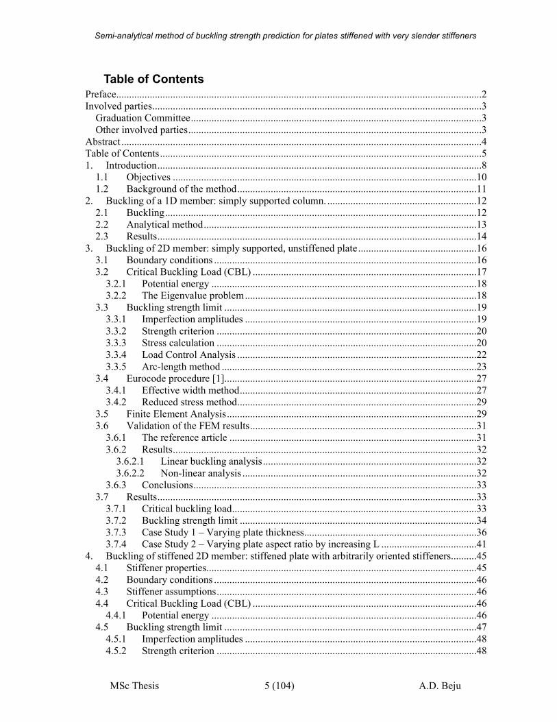
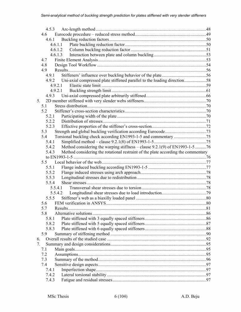
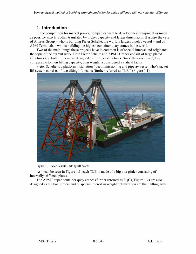
Pieter Schelte is a platform installation / decommissioning and pipelay vessel who’s jacket
lift system consists of two tilting lift beams (further referred as TLBs) (Figure 1.1).
Figure 1.1 Pieter Schelte – tilting lift beams
As it can be seen in Figure 1.1, each TLB is made of a big box girder consisting of
internally stiffened plates.
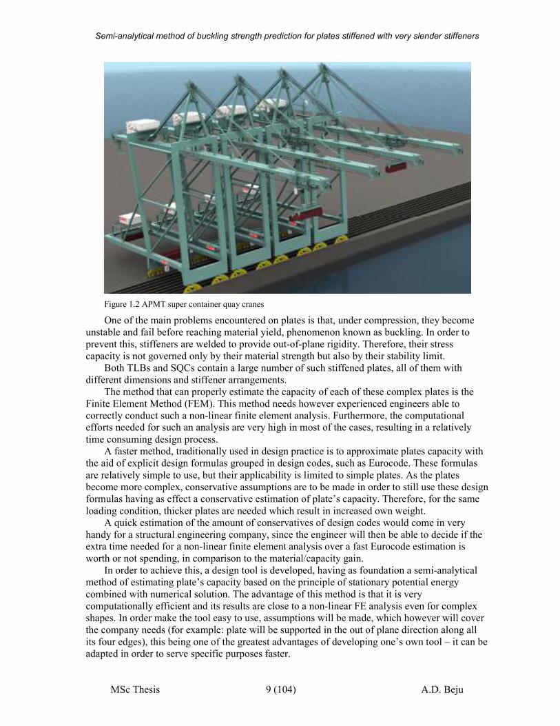
The APMT super container quay cranes (further referred as SQCs, Figure 1.2) are also
designed as big box girders and of special interest in weight optimization are their lifting arms.
Semi-analytical method of buckling strength prediction for plates stiffened with very slender stiffeners
MSc Thesis 9 (104) A.D. Beju
Figure 1.2 APMT super container quay cranes
One of the main problems encountered on plates is that, under compression, they become
unstable and fail before reaching material yield, phenomenon known as buckling. In order to
prevent this, stiffeners are welded to provide out-of-plane rigidity. Therefore, their stress
capacity is not governed only by their material strength but also by their stability limit.
Both TLBs and SQCs contain a large number of such stiffened plates, all of them with
different dimensions and stiffener arrangements.
The method that can properly estimate the capacity of each of these complex plates is the
Finite Element Method (FEM). This method needs however experienced engineers able to
correctly conduct such a non-linear finite element analysis. Furthermore, the computational efforts needed for such an analysis are very high in most of the cases, resulting in a relatively
time consuming design process.
A faster method, traditionally used in design practice is to approximate plates capacity with
the aid of explicit design formulas grouped in design codes, such as Eurocode. These formulas
are relatively simple to use, but their applicability is limited to simple plates. As the plates
become more complex, conservative assumptions are to be made in order to still use these design
formulas having as effect a conservative estimation of plate’s capacity. Therefore, for the same
loading condition, thicker plates are needed which result in increased own weight.
A quick estimation of the amount of conservatives of design codes would come in very
handy for a structural engineering company, since the engineer will then be able to decide if the extra time needed for a non-linear finite element analysis over a fast Eurocode estimation is
worth or not spending, in comparison to the material/capacity gain.
In order to achieve this, a design tool is developed, having as foundation a semi-analytical
method of estimating plate’s capacity based on the principle of stationary potential energy
combined with numerical solution. The advantage of this method is that it is very
computationally efficient and its results are close to a non-linear FE analysis even for complex
shapes. In order make the tool easy to use, assumptions will be made, which however will cover
the company needs (for example: plate will be supported in the out of plane direction along all
its four edges), this being one of the greatest advantages of developing one’s own tool – it can be
adapted in order to serve specific purposes faster.
Semi-analytical method of buckling strength prediction for plates stiffened with very slender stiffeners
MSc Thesis 10 (104) A.D. Beju
As stated before, for both TLBs and SQCs own-weight is considered critical due to their
lifting function. Even if it may involve more accurate investigation, leading to time cost, in such
cases, the amount of material that can be reduced does not represent only a save in material, but
the most important gain is in overall lifting capacity. The amount of own weight that can be
saved on these structures while maintaining the same stress capacity, converts into lifting
capacity. This is very important as it does not represent a short term manufacturing gain, but a long term performance gain.
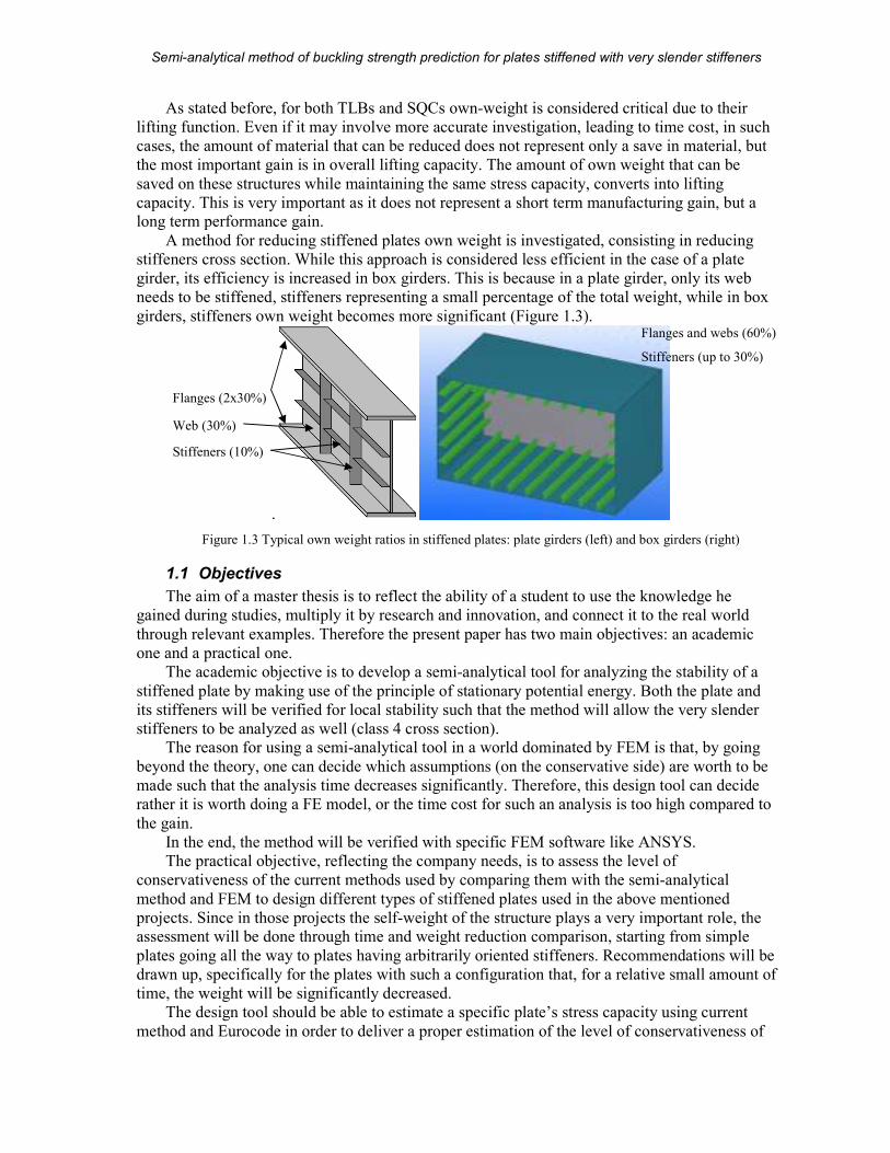
A method for reducing stiffened plates own weight is investigated, consisting in reducing
stiffeners cross section. While this approach is considered less efficient in the case of a plate
girder, its efficiency is increased in box girders. This is because in a plate girder, only its web
needs to be stiffened, stiffeners representing a small percentage of the total weight, while in box
girders, stiffeners own weight becomes more significant (Figure 1.3).
.
Figure 1.3 Typical own weight ratios in stiffened plates: plate girders (left) and box girders (right)
1.1 Objectives
The aim of a master thesis is to reflect the ability of a student to use the knowledge he
gained during studies, multiply it by research and innovation, and connect it to the real world
through relevant examples. Therefore the present paper has two main objectives: an academic
one and a practical one.
The academic objective is to develop a semi-analytical tool for analyzing the stability of a
stiffened plate by making use of the principle of stationary potential energy. Both the plate and
its stiffeners will be verified for local stability such that the method will allow the very slender
stiffeners to be analyzed as well (class 4 cross section). The reason for using a semi-analytical tool in a world dominated by FEM is that, by going
beyond the theory, one can decide which assumptions (on the conservative side) are worth to be
made such that the analysis time decreases significantly. Therefore, this design tool can decide
rather it is worth doing a FE model, or the time cost for such an analysis is too high compared to
the gain.
In the end, the method will be verified with specific FEM software like ANSYS.
The practical objective, reflecting the company needs, is to assess the level of
conservativeness of the current methods used by comparing them with the semi-analytical
method and FEM to design different types of stiffened plates used in the above mentioned
projects. Since in those projects the self-weight of the structure plays a very important role, the assessment will be done through time and weight reduction comparison, starting from simple
plates going all the way to plates having arbitrarily oriented stiffeners. Recommendations will be
drawn up, specifically for the plates with such a configuration that, for a relative small amount of
time, the weight will be significantly decreased.
The design tool should be able to estimate a specific plate’s stress capacity using current
method and Eurocode in order to deliver a proper estimation of the level of conservativeness of
Flanges (2x30%)
Stiffeners (10%)
Web (30%)
Flanges and webs (60%)
Stiffeners (up to 30%)
Semi-analytical method of buckling strength prediction for plates stiffened with very slender stiffeners
MSc Thesis 11 (104) A.D. Beju
the latter one. It will also determine a slender stiffener cross section that can be used instead,
without decreasing plate’s capacity.
Therefore the main goals of current master thesis are as follows:
1. Develop a tool that estimates a stiffened plate’s buckling strength based on analytical
method, gaining therefore detailed insight on the theory behind buckling of plates
2. Estimate the amount of conservativeness of the Eurocode with respect to non-linear finite
element analysis
3. Analyze the possibility of weight reduction in stiffened plates by using stiffeners with
thin webs
1.2 Background of the method
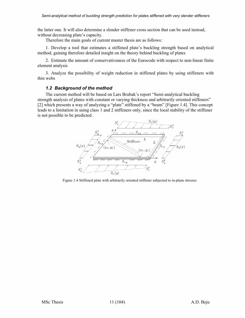
The current method will be based on Lars Brubak’s report “Semi-analytical buckling
strength analysis of plates with constant or varying thickness and arbitrarily oriented stiffeners”
[2] which presents a way of analyzing a “plate” stiffened by a “beam” [Figure 1.4]. This concept
leads to a limitation in using class 1 and 2 stiffeners only, since the local stability of the stiffener
is not possible to be predicted .
Figure 1.4 Stiffened plate with arbitrarily oriented stiffener subjected to in-plane stresses
Semi-analytical method of buckling strength prediction for plates stiffened with very slender stiffeners
MSc Thesis 12 (104) A.D. Beju
2. Buckling of a 1D member: simply supported column.
2.1 Buckling
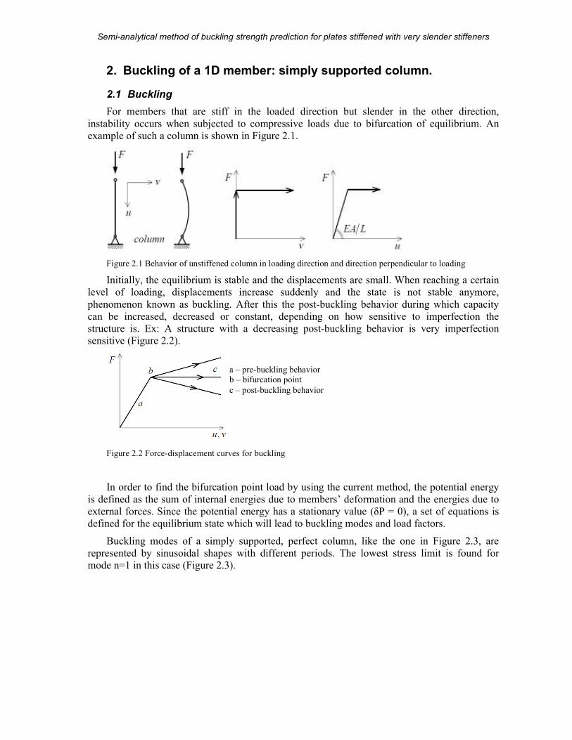
For members that are stiff in the loaded direction but slender in the other direction,
instability occurs when subjected to compressive loads due to bifurcation of equilibrium. An
example of such a column is shown in Figure 2.1.
Figure 2.1 Behavior of unstiffened column in loading direction and direction perpendicular to loading
Initially, the equilibrium is stable and the displacements are small. When reaching a certain
level of loading, displacements increase suddenly and the state is not stable anymore,
phenomenon known as buckling. After this the post-buckling behavior during which capacity
can be increased, decreased or constant, depending on how sensitive to imperfection the
structure is. Ex: A structure with a decreasing post-buckling behavior is very imperfection
sensitive (Figure 2.2).
Figure 2.2 Force-displacement curves for buckling
In order to find the bifurcation point load by using the current method, the potential energy
is defined as the sum of internal energies due to members’ deformation and the energies due to
external forces. Since the potential energy has a stationary value (δP = 0), a set of equations is
defined for the equilibrium state which will lead to buckling modes and load factors.
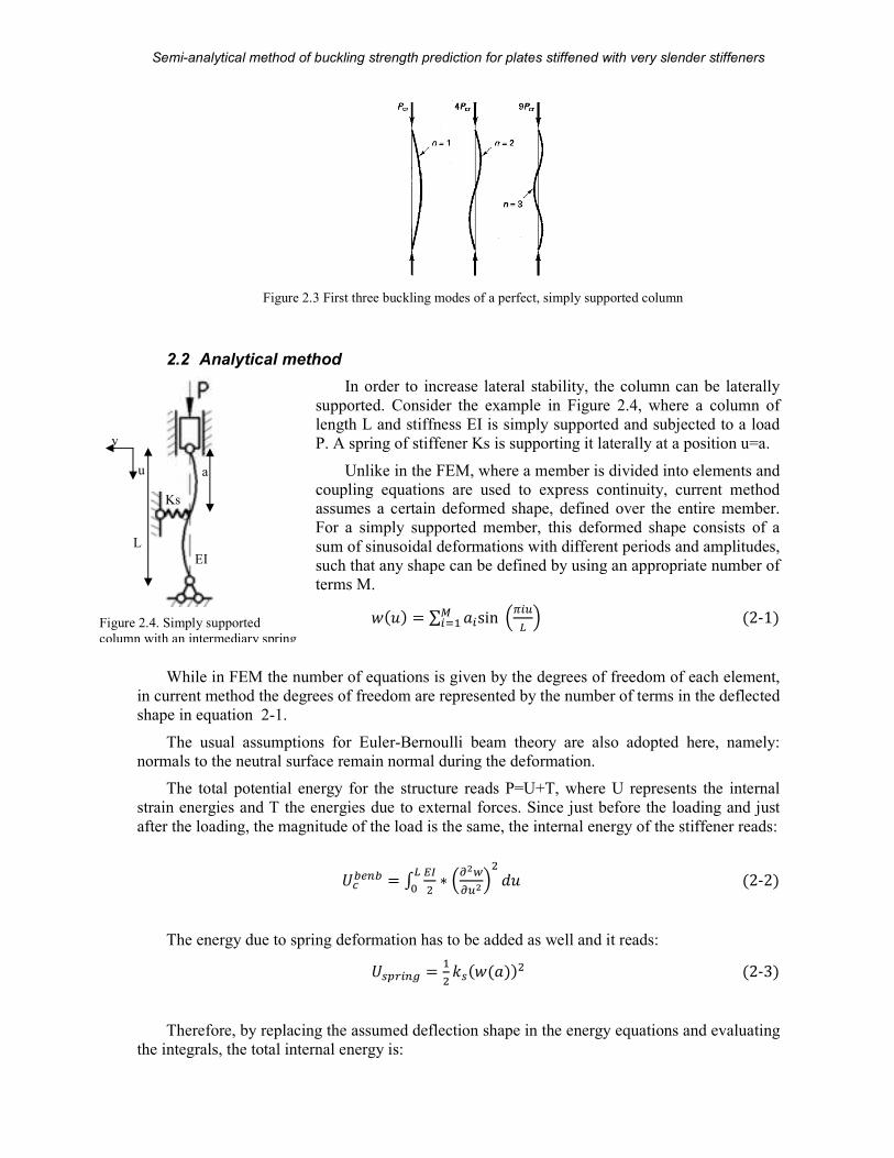
Buckling modes of a simply supported, perfect column, like the one in Figure 2.3, are
represented by sinusoidal shapes with different periods. The lowest stress limit is found for
mode n=1 in this case (Figure 2.3).
a – pre-buckling behavior
b – bifurcation point
c – post-buckling behavior
Semi-analytical method of buckling strength prediction for plates stiffened with very slender stiffeners
MSc Thesis 13 (104) A.D. Beju
Figure 2.3 First three buckling modes of a perfect, simply supported column
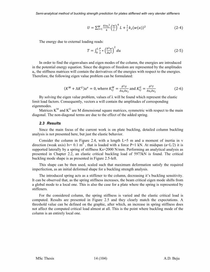
2.2 Analytical method
In order to increase lateral stability, the column can be laterally
supported. Consider the example in Figure 2.4, where a column of
length L and stiffness EI is simply supported and subjected to a load
P. A spring of stiffener Ks is supporting it laterally at a position u=a.
Unlike in the FEM, where a member is divided into elements and
coupling equations are used to express continuity, current method assumes a certain deformed shape, defined over the entire member.
For a simply supported member, this deformed shape consists of a
sum of sinusoidal deformations with different periods and amplitudes,
such that any shape can be defined by using an appropriate number of
terms M.
���� � ∑ ��sin ���� ����� �2-1�
While in FEM the number of equations is given by the degrees of freedom of each element,
in current method the degrees of freedom are represented by the number of terms in the deflected
shape in equation 2-1.
The usual assumptions for Euler-Bernoulli beam theory are also adopted here, namely:
normals to the neutral surface remain normal during the deformation.
The total potential energy for the structure reads P=U+T, where U represents the internal
strain energies and T the energies due to external forces. Since just before the loading and just
after the loading, the magnitude of the load is the same, the internal energy of the stiffener reads:
������ � � �� ∗ "#$"�#� �% &� �2-2�
The energy due to spring deformation has to be added as well and it reads:
�'()��* � � +'������ �2-3�
Therefore, by replacing the assumed deflection shape in the energy equations and evaluating
the integrals, the total internal energy is:
u
Figure 2.4. Simply supported
column with an intermediary spring
L
a
v
u
Ks
EI
Semi-analytical method of buckling strength prediction for plates stiffened with very slender stiffeners
MSc Thesis 14 (104) A.D. Beju
� � ∑ ��-.#/ ��� �/ 0���� + � +'������ �2-4�
The energy due to external loading reads:
3 � � 4 ∗ "#$"�#� �% &� �2-5�
In order to find the eigenvalues and eigen modes of the column, the energies are introduced
in the potential energy equation. Since the degrees of freedom are represented by the amplitudes
ai, the stiffness matrices will contain the derivatives of the energies with respect to the energies.
Therefore, the following eigen value problem can be formulated:
�6� + Λ68��� � 0,where6�?� � "#@"-."-Aand6�?8 � "#D"-."-A �2-6�By solving the eigen value problem, values of λ will be found which represent the elastic
limit load factors. Consequently, vectors a will contain the amplitudes of corresponding eigenmodes.
Matrices KM
and KG are M dimensional square matrices, symmetric with respect to the main
diagonal. The non-diagonal terms are due to the effect of the added spring.
2.3 Results
Since the main focus of the current work is on plate buckling, detailed column buckling
analysis is not presented here, but just the elastic behavior.
Consider the column in Figure 2.4, with a length L=5 m and a moment of inertia in v
direction (weak axis) Iv= 0.1 m4 , that is loaded with a force P=1 kN. At midspan (a=L/2) it is
supported laterally by a spring of stiffness Ks=2000 N/mm. Performing an analytical analysis as
presented in Chapter 2.2, an elastic critical buckling load of 5973kN is found. The critical
buckling mode shape is as presented in Figure 2.5-left.
This shape can be then used, scaled such that maximum deformation satisfy the required
imperfection, as an initial deformed shape for a buckling strength analysis.
The introduced spring acts as a stiffener to the column, decreasing it’s buckling sensitivity.
It can be observed that, as the spring stiffness increases, the beam critical eigen mode shifts from
a global mode to a local one. This is also the case for a plate where the spring is represented by
stiffeners.
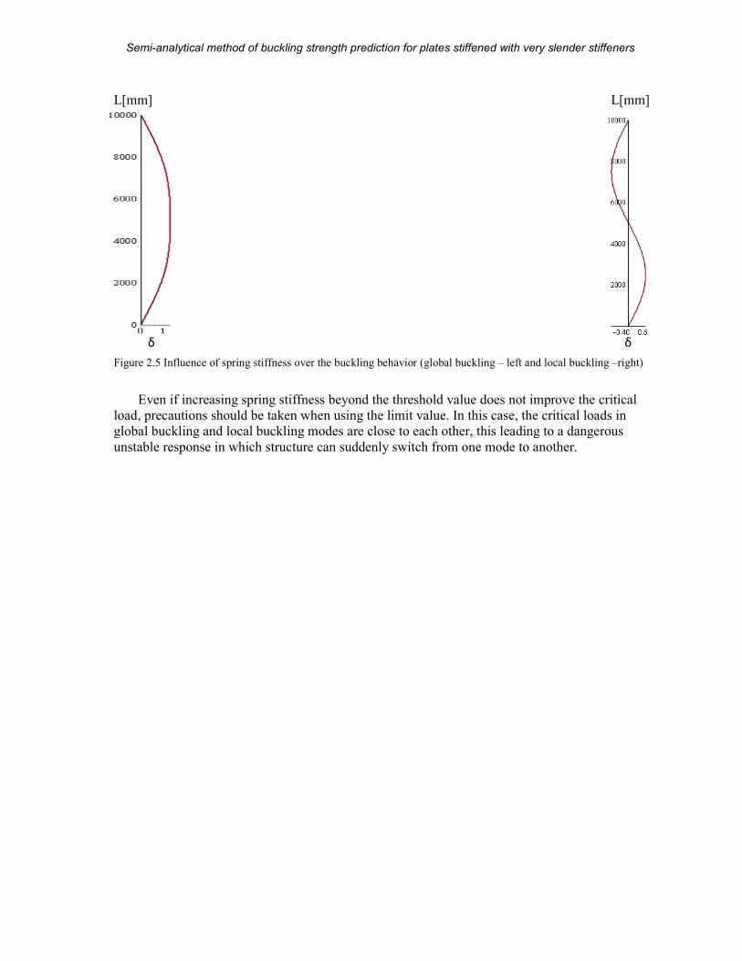
For the considered column, the spring stiffness is varied and the elastic critical load is
computed. Results are presented in Figure 2.5 and they clearly match the expectations. A
threshold value can be defined on the graphic, after which, an increase in spring stiffness does
not affect the computed critical load almost at all. This is the point where buckling mode of the
column is an entirely local one.
Semi-analytical method of buckling strength prediction
MSc Thesis
Figure 2.5 Influence of spring stiffness over the buckling behavior (global buckling
Even if increasing spring stiffness beyond the threshold value does not improve the critical
load, precautions should be taken when using the limit value. In this case, the critical loads in
global buckling and local buckling modes are close to each other, this leading to a dan
unstable response in which structure can suddenly switch from one mode to another.
L[mm]
δ
analytical method of buckling strength prediction for plates stiffened with very slender stiffeners
15 (104)
Influence of spring stiffness over the buckling behavior (global buckling – left and local buckling
ing stiffness beyond the threshold value does not improve the critical
load, precautions should be taken when using the limit value. In this case, the critical loads in
global buckling and local buckling modes are close to each other, this leading to a dan
unstable response in which structure can suddenly switch from one mode to another.
plates stiffened with very slender stiffeners
A.D. Beju
left and local buckling –right)
ing stiffness beyond the threshold value does not improve the critical
load, precautions should be taken when using the limit value. In this case, the critical loads in
global buckling and local buckling modes are close to each other, this leading to a dangerous
unstable response in which structure can suddenly switch from one mode to another.
L[mm]
δ
Semi-analytical method of buckling strength prediction for plates stiffened with very slender stiffeners
MSc Thesis 16 (104) A.D. Beju
3. Buckling of 2D member: simply supported, unstiffened plate
Figure 3.1 Unstiffened plate subjected to in-plane shear and in-plane compression and tension
The concept shown in Chapter 2.2 will now be extrapolated now for a plate of thickness t,
like the one shown in Figure 3.1. Procedure of current method will be presented, as well as the
procedure in the Eurocode and FEM analysis, all of them being compared through examples.
Again, the energies will be computed and their derivatives with respect to amplitudes will
form the stiffness matrices, thus the deflected shape will be obtained.
The analysis will be carried out in 2 major steps, namely: Critical Buckling Load (further
referred as CBL) and Buckling Strength Limit (further referred as BSL).
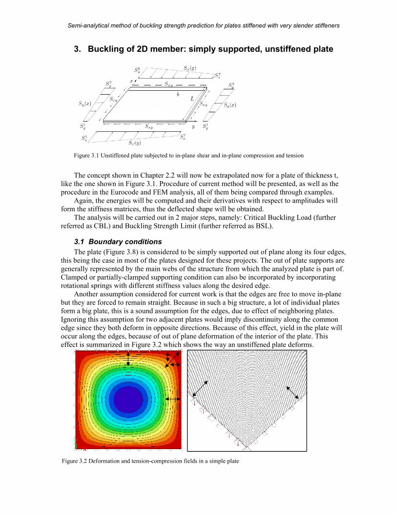
3.1 Boundary conditions
The plate (Figure 3.8) is considered to be simply supported out of plane along its four edges,
this being the case in most of the plates designed for these projects. The out of plate supports are
generally represented by the main webs of the structure from which the analyzed plate is part of.
Clamped or partially-clamped supporting condition can also be incorporated by incorporating rotational springs with different stiffness values along the desired edge.
Another assumption considered for current work is that the edges are free to move in-plane
but they are forced to remain straight. Because in such a big structure, a lot of individual plates
form a big plate, this is a sound assumption for the edges, due to effect of neighboring plates.
Ignoring this assumption for two adjacent plates would imply discontinuity along the common
edge since they both deform in opposite directions. Because of this effect, yield in the plate will
occur along the edges, because of out of plane deformation of the interior of the plate. This
effect is summarized in Figure 3.2 which shows the way an unstiffened plate deforms.
Figure 3.2 Deformation and tension-compression fields in a simple plate
Semi-analytical method of buckling strength prediction for plates stiffened with very slender stiffeners
MSc Thesis 17 (104) A.D. Beju
The same principle applies along stiffeners which can be seen as flexible supports, partially
restraining out-of-plane displacements.
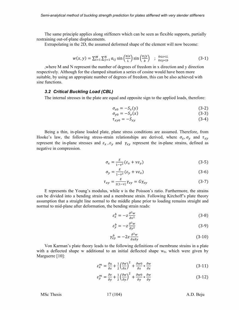
Extrapolating in the 2D, the assumed deformed shape of the element will now become:
��F, G� � ∑ ∑ ��? sin ��H� � sin �?I� �J?������ ; %LHM�%LIM� �3-1�,where M and N represent the number of degrees of freedom in x direction and y direction
respectively. Although for the clamped situation a series of cosine would have been more
suitable, by using an appropiate number of degrees of freedom, this can be also achieved with
sine functions.
3.2 Critical Buckling Load (CBL)
The internal stresses in the plate are equal and opposite sign to the applied loads, therefore:
NH% � −PH�G� �3-2�NI% � −PI�F� �3-3�QHI% � −PHI �3-4�
Being a thin, in-plane loaded plate, plane stress conditions are assumed. Therefore, from
Hooke’s law, the following stress-strain relationships are derived, where NH,NI and QHI
represent the in-plane stresses and RH , RI and SHI represent the in-plane strains, defined as
negative in compression.
NH � ��TU# �RH + VRI� �3-5�NI � ��TU# �RI + VRH� �3-6�QHI � � ��TU� SHI � WSHI �3-7�
E represents the Young’s modulus, while ν is the Poisson’s ratio. Furthermore, the strains
can be divided into a bending strain and a membrane strain. Following Kirchoff’s plate theory
assumption that a straight line normal to the middle plane prior to loading remains straight and
normal to mid-plane after deformation, the bending strain reads:
RH� � −Y "#$"H# �3-8�RI� � −Y "#$"I# �3-9�SHI� � −2Y "#$"H"I �3-10�
Von Karman’s plate theory leads to the following definitions of membrane strains in a plate
with a deflected shape w additional to an initial deflected shape w0, which were given by
Marguerre [10]:
RH\ � "�"H + � "$"H� + "$%"H ∗ "$"H �3-11�RI\ � "]"I + � "$"I� + "$%"I ∗ "$"I �3-12�
Semi-analytical method of buckling strength prediction for plates stiffened with very slender stiffeners
MSc Thesis 18 (104) A.D. Beju
SHI\ � "�"H + "]"I + "$"H ∗ "$"I + "$^"I ∗ "$"I + "$^"H ∗ "$"H �3-13�Here, u and v represents the displacement of the middle plane of the plate in x and y
direction respectively. For the CBL, initial displacements are set to zero. However in the BSL,
they will represent plate’s imperfections.
3.2.1 Potential energy
Again, the principle of stationary potential energy should be satisfied. _Π � _U + _T � 0 �3-14�The internal energy for the plate in Figure 3.1 consists of the bending strain energy of a
plate, which is:
�(� � � � �cd /��TU#� ∗ e "#$"H# + "#$"I#� − 2�1 − V� "#$"H# "#$"I# − "#$"H"I� f�%�% &F &G �3-15�The membrane energy does not affect the computed eigenvalues and therefore does not need
to be included [2].
In order to express a clamped supported condition, energy due to rotational springs along
the desired portion of the edge (Ls) must be added. The clamping condition (fully or partially) is
given by the spring stiffness ks. Being a rotational spring along a line, this energy is a function of
the derivative of the deflected shape normal to the edge.
�)gc � � � +' "$"�� &0'�h �3-16�The potential energy of the external loads of the column in chapter 2 is extrapolated to a 2D
member loaded with in-plane biaxial compression or tension, as well as in plane shear, which are
the loading conditions of the plate in Figure 3.1. This reads:
3 � � � c eNH% "$"H� + NI% "$"I� + 2QHI "$"H ∗ "$"If &G &F�%�% �3-17�By substituting the assumed displacement field in the energy equations and evaluating them
analytically, the stiffness matrices are found right away.
3.2.2 The Eigenvalue problem
The same as for the column, the eigenvalue problem is defined as: �6� + Λ68��� � 0 �3-18�The degrees of freedom are again represented by the amplitudes in the deflected shape
equation. Since in 2D there will be M*N modes, and therefore amplitudes, KM
and KG will be
M*N dimensional square matrices, symmetric with respect to the main diagonal. Non-diagonal
terms are due to effect of added springs. Matrices elements will be now dependent on 4 indices
(unlike in the column stiffness matrices) and their elements will be: 6�?ij� � "#@"-.A"-kl �3-19�
6�?ij8 � "#D"-.A"-kl �3-20�, where U and T are the energies defined in chapter 3.2.1 and aij are the amplitudes of the
deflected shape.
Since the stiffness matrices are 2-dimensional while the elements depends on four indices,
in order to verify the symmetric condition as well as to give consistency in the resulting
Semi-analytical method of buckling strength prediction for plates stiffened with very slender stiffeners
MSc Thesis 19 (104) A.D. Beju
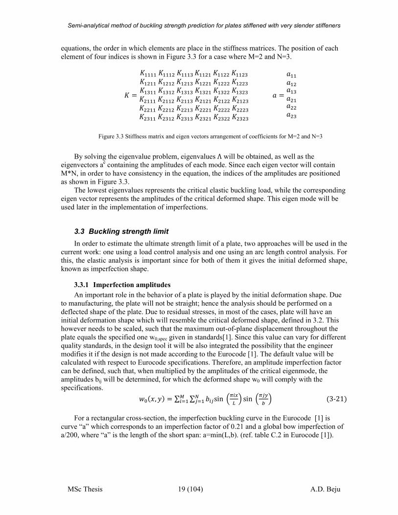
equations, the order in which elements are place in the stiffness matrices. The position of each
element of four indices is shown in Figure 3.3 for a case where M=2 and N=3.
6 �6����6��� 6���m6�� �6�� 6�� m6� ��6� � 6� �m6� �6� 6� m6�m��6�m� 6�m�m6�m �6�m 6�m m6 ���6 �� 6 ��m6 � �6 � 6 � m6 ��6 � 6 �m6 �6 6 m6 m��6 m� 6 m�m6 m �6 m 6 m m
� ������ ��m� �� � m
Figure 3.3 Stiffness matrix and eigen vectors arrangement of coefficients for M=2 and N=3
By solving the eigenvalue problem, eigenvalues Λ will be obtained, as well as the eigenvectors a
e containing the amplitudes of each mode. Since each eigen vector will contain
M*N, in order to have consistency in the equation, the indices of the amplitudes are positioned
as shown in Figure 3.3.
The lowest eigenvalues represents the critical elastic buckling load, while the corresponding
eigen vector represents the amplitudes of the critical deformed shape. This eigen mode will be
used later in the implementation of imperfections.
3.3 Buckling strength limit
In order to estimate the ultimate strength limit of a plate, two approaches will be used in the
current work: one using a load control analysis and one using an arc length control analysis. For
this, the elastic analysis is important since for both of them it gives the initial deformed shape,
known as imperfection shape.
3.3.1 Imperfection amplitudes
An important role in the behavior of a plate is played by the initial deformation shape. Due
to manufacturing, the plate will not be straight; hence the analysis should be performed on a
deflected shape of the plate. Due to residual stresses, in most of the cases, plate will have an
initial deformation shape which will resemble the critical deformed shape, defined in 3.2. This
however needs to be scaled, such that the maximum out-of-plane displacement throughout the
plate equals the specified one w0,spec given in standards[1]. Since this value can vary for different
quality standards, in the design tool it will be also integrated the possibility that the engineer
modifies it if the design is not made according to the Eurocode [1]. The default value will be calculated with respect to Eurocode specifications. Therefore, an amplitude imperfection factor
can be defined, such that, when multiplied by the amplitudes of the critical eigenmode, the
amplitudes bij will be determined, for which the deformed shape w0 will comply with the
specifications. �%�F, G� � ∑ ∑ n�?sin ��H� � sin �?I� �J?������ �3-21�For a rectangular cross-section, the imperfection buckling curve in the Eurocode [1] is
curve “a” which corresponds to an imperfection factor of 0.21 and a global bow imperfection of
a/200, where “a” is the length of the short span: a=min(L,b). (ref. table C.2 in Eurocode [1]).
Semi-analytical method of buckling strength prediction for plates stiffened with very slender stiffeners
MSc Thesis 20 (104) A.D. Beju
3.3.2 Strength criterion
When predicting the ultimate buckling strength, various strength defining criteria can be
used.
For thin plates the limit is considered to be reached when the von Misses membrane stresses
in the mid-plane of the plate reach the yield limit. It reads:
N�\ � o�NH\� + pNI\q − NH\NI\ + 3pQHI\ q < sI �3-22� Brubak [6] has demonstrated that this is un-conservative in some cases, especially for
thicker plates and plates in global bending, where the variation of the stresses though plates’
thickness varies due to bending stress variation.
Therefore the criterion has been modified by adding the contribution of the bending stresses
as well. This is done on an analogy to the plastic capacity interaction formula for rectangular
cross section [6] by considering the plate subjected to a combination of axial load and bending
moment. The unity check then becomes:
tuvwxy z + �{ uv|,w}~xy � 1,�ℎ���� � 1.5 �3-23�
This is similar to the plastic capacity of a rectangular section which reads:
t JJ�z + ��� � 1 �3-24�
Since the strength criterion will be first reached where changes of stiffness occur, for
optimization, the verification will be done only at these positions which for an irregularly
stiffened plate can be located along the supports, the stiffeners or the introduced springs.
Furthermore, in an unstiffened rectangular plate, their possible location is reduced to three points only, namely: corner point and projections of the point of maximum deformation on two
perpendicular edges. For an orthogonally stiffened plate, in addition to the previously specified
three, also the projections of the coordinates of the maximum amplitude to the intersection lines
between plate and stiffeners have to be checked.
3.3.3 Stress calculation
For any deformed shape of the plate, the coordinate stresses can be computed by solving the
plate compatibility equation. The latter is obtained by differentiation and combination of the
strain equations for a plate with initial deformed shape w0, given in equations (3-11) – (3-13)
and it reads: "#�~w"I# + "#�yw"H# + "#�~yw"H"I � "#$"H"I� − "#$"H# "#$"I# + 2 "#$^"H"I "#$"H"I − "#$^"H# "#$"I# − "#$^"I# "#$"H# �3-25�In order to find the stresses in the membrane, Airy’s stress function F(x,y) is defined, which
contains the combination of the effects of the three types of stresses. Therefore, the membrane
stresses are given by:
Semi-analytical method of buckling strength prediction for plates stiffened with very slender stiffeners
MSc Thesis 21 (104) A.D. Beju
NH\ � "#x"H# �3-26�NI\ � "#x"I# �3-27�QHI\ � − "#x"H"I �3-28�If the strains in equation 3-25 are substituted by the ones in Hooke’s law, and furthermore
by Airy’s stress function, the following nonlinear plate compatibility equation is found which
relates stresses in the plate to out of plane displacements: ∇/s � � ∗ e "#$"H"I� − "#$"H# "#$"I# + 2 "#$^"H"I "#$"H"I− "#$^"H# "#$"I# − "#$^"I# "#$"H# f �3-29�, with w0 as defined in equation 3-1. A solution for the equation was proposed by Levy [11]
for perfect plates (w0=0):
s�F, G� � Λ � NH%\G + � NI%\F − QHI\ FG� + ∑ ∑ ��?cos ��H� � cos �?I� � J?�% ���% �3-30�By substituting F(x,y), w and w0 into the plate compatibility equation, Byklum and Amdahl
[12] defined the coefficients fij that are also valid for imperfect plates and they are given by:
��? � �/ �#|��?#�|�#∑ ∑ ∑ ∑ �)'(�p�)'�(� + �)'n(� + �(�n)'qJ����(��J'���)�� �3-31�
, where �%% � 0, a and b are the amplitudes of w and w0 respectively and
�)'(� � ����� + � � ���±�� − �� � ���&� + � � ������ + � � ���& ± �� − �� � ������ − � � ���±�� − �� � ���& ± �� − �� � ������ + � � ���&� + � � ��0, ��ℎ������ � �3-32�
As it can be seen, F(x,y) can be split into a linear part F
L, representing the contribution of
the external applied stresses, and a non-linear one FNL
which represents the redistribution of
stresses due to out of plane displacements.
s�F, G� � F� + FJ� �3-33�F� � Λ � NH%\G + � NI%\F − QHI\ FG� �3-34�FJ� � ∑ ∑ ��?cos ��H� � cos �?I� � J?�% ���% �3-35�
Semi-analytical method of buckling strength prediction for plates stiffened with very slender stiffeners
MSc Thesis 22 (104) A.D. Beju
3.3.4 Load Control Analysis
One method of tracing the load-displacement curve is to gradually increase the load and use
it to approximate the displacements. Once they are known, the stress in the plate can be derived
and then check if the strength criteria has been reached. This method is known as “load control
analysis” and it will be further referred as LCA. The maximum value for which the strength
criterion is still verified will represent the buckling strength of the plate.
Any stage of loading is represented by the load factor Λ while the value of the external
stresses will be: PH�Λ� � Λ ∗PH%�G� �3-36�PI�Λ� � Λ ∗PI%�F� �3-37�PHI�Λ� � Λ ∗PHI% �3-38�The initial deformed shape of the structure is given by the critical eigen mode. Therefore,
since this is related to the critical eigenvalue, a displacement magnification factor is defined in
order to relate the additional deflection w at a certain load stage to the load factor Λ at that stage. This is given by: � � ��� T� ∗ �% �3-39�
Similar factors are also found in the Eurocode for column buckling, being used to compute
the buckling strength reduction factors (Ex: EC1993-1-1 Annex A, interaction factors kyy and
kzz).
It can however be easily observed that load factor will always be smaller than the first eigenvalue, limitation which leads to the main disadvantage of this method: it is not able to trace
the post-buckling behavior of the plate. This behavior is graphically presented in Figure 3.5.
The presented approximation of the displacements is however on the conservative side,
especially for plates having high slenderness. Since the initial deformations become more and
more important with increasing slenderness of the plate, in order to compensate, Brubak [2] has
defined slenderness dependent reduced imperfection amplitude as a fraction of the specified one,
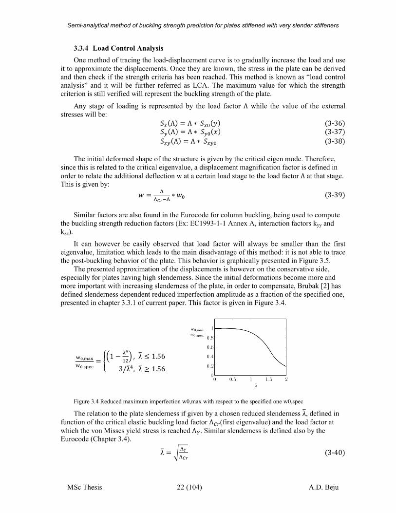
presented in chapter 3.3.1 of current paper. This factor is given in Figure 3.4.
¡^,¢£¤¡^,¥¦§¨ � © 1 − ª«¬� � , λ® ≤ 1.563/λ®/, λ® ≥ 1.56�
Figure 3.4 Reduced maximum imperfection w0,max with respect to the specified one w0,spec
The relation to the plate slenderness if given by a chosen reduced slenderness λ®, defined in
function of the critical elastic buckling load factor Λ²)(first eigenvalue) and the load factor at
which the von Misses yield stress is reached Λ³. Similar slenderness is defined also by the Eurocode (Chapter 3.4).
λ® � o �´�� �3-40�
Semi-analytical method of buckling strength prediction
MSc Thesis
The load factor at which the von Misses yield stress is reached
yield stress of the material by the equivalent von Misses
N�% � o�NH%�
The method is used iteratively, by gradually increasing the load factor until the given
strength criteria is reached. At each stage “k” in the process, for a value
are computed using the displacement magnifier. Then the internal stress computation is
performed and a unity check uck
convergence towards a value is obtained by optimizing this
results of the previous calculations. The load factor for the next stage, Λi�� � Λi + �Λ²) − Λi� ∗ �Another optimization in finding the buckling strength of the plate is presented in 3.2.2, by
checking the strength criterion only in cri
found, the stress function in 3.2.3 is used to compute the internal stresses
A short analysis result is presented in
the load control analysis. Since for the slender plates which are mainly of interest to the scope of
current work this method is not able to lead to accurate results, its results are left outside further comparisons.
Figure 3.5 Load control analysis results
3.3.5 Arc-length method
While in the load control analysis, the load factor is specified and the displacements are
computed, in the arc-length method (further referred as ALM)
function of an arc-length along the equilibrium path.may be therefore considered a pseudo
Δη from a state “k” to a state “k+1”.
also the principle of the stationary potential will be used in a r
analytical method of buckling strength prediction for plates stiffened with very slender stiffeners
23 (104)
load factor at which the von Misses yield stress is reached, Λ³ is found by div
yield stress of the material by the equivalent von Misses stress N�%, being defined
Λ³ � xyuv̂ � + pNI%q − NH%NI% + 3pQHI%q
The method is used iteratively, by gradually increasing the load factor until the given
strength criteria is reached. At each stage “k” in the process, for a value Λi, the displacements
are computed using the displacement magnifier. Then the internal stress computation is
for these with respect to the strength criteria is given. The
convergence towards a value is obtained by optimizing this gradual increase in function of the
results of the previous calculations. The load factor for the next stage, Λi��is given by:
� �1 − ��µ�, which is a common convergence optimization factor.
Another optimization in finding the buckling strength of the plate is presented in 3.2.2, by
checking the strength criterion only in critical points. However, after the buckling
found, the stress function in 3.2.3 is used to compute the internal stresses over the entire plate.
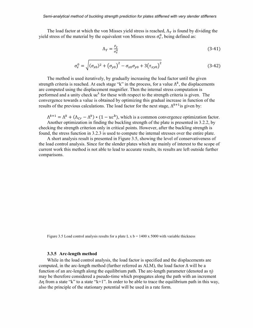
A short analysis result is presented in Figure 3.5, showing the level of conservativeness of
the load control analysis. Since for the slender plates which are mainly of interest to the scope of
current work this method is not able to lead to accurate results, its results are left outside further
Load control analysis results for a plate L x b = 1400 x 5000 with variable thickness
While in the load control analysis, the load factor is specified and the displacements are
length method (further referred as ALM), the load factor Λ
length along the equilibrium path. The arc-length parameter (denoted as η)may be therefore considered a pseudo-time which propagates along the path with an increment
Δη from a state “k” to a state “k+1”. In order to be able to trace the equilibrium path in this way,
also the principle of the stationary potential will be used in a rate form.
plates stiffened with very slender stiffeners
A.D. Beju
is found by dividing the
defined as:
�3-41� �3-42�
The method is used iteratively, by gradually increasing the load factor until the given
e displacements
are computed using the displacement magnifier. Then the internal stress computation is
for these with respect to the strength criteria is given. The
gradual increase in function of the
is given by:
, which is a common convergence optimization factor.
Another optimization in finding the buckling strength of the plate is presented in 3.2.2, by
buckling strength is
over the entire plate.
servativeness of
the load control analysis. Since for the slender plates which are mainly of interest to the scope of
current work this method is not able to lead to accurate results, its results are left outside further
for a plate L x b = 1400 x 5000 with variable thickness
While in the load control analysis, the load factor is specified and the displacements are
will be a
(denoted as η) propagates along the path with an increment
to trace the equilibrium path in this way,
Semi-analytical method of buckling strength prediction for plates stiffened with very slender stiffeners
MSc Thesis 24 (104) A.D. Beju
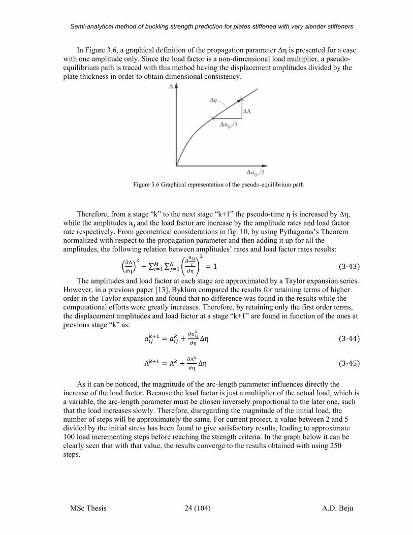
In Figure 3.6, a graphical definition of the propagation parameter Δη is presented for a case
with one amplitude only. Since the load factor is a non-dimensional load multiplier, a pseudo-
equilibrium path is traced with this method having the displacement amplitudes divided by the
plate thickness in order to obtain dimensional consistency.
Figure 3.6 Graphical representation of the pseudo-equilibrium path
Therefore, from a stage “k” to the next stage “k+1” the pseudo-time η is increased by Δη,
while the amplitudes aij and the load factor are increase by the amplitude rates and load factor
rate respectively. From geometrical considerations in fig. 10, by using Pythagoras’s Theorem
normalized with respect to the propagation parameter and then adding it up for all the
amplitudes, the following relation between amplitudes’ rates and load factor rates results:
"�"¶� + ∑ ∑ ·"£.A¸"¶ ¹ J?������ � 1 �3-43�
The amplitudes and load factor at each stage are approximated by a Taylor expansion series.
However, in a previous paper [13], Byklum compared the results for retaining terms of higher
order in the Taylor expansion and found that no difference was found in the results while the
computational efforts were greatly increases. Therefore, by retaining only the first order terms,
the displacement amplitudes and load factor at a stage “k+1” are found in function of the ones at
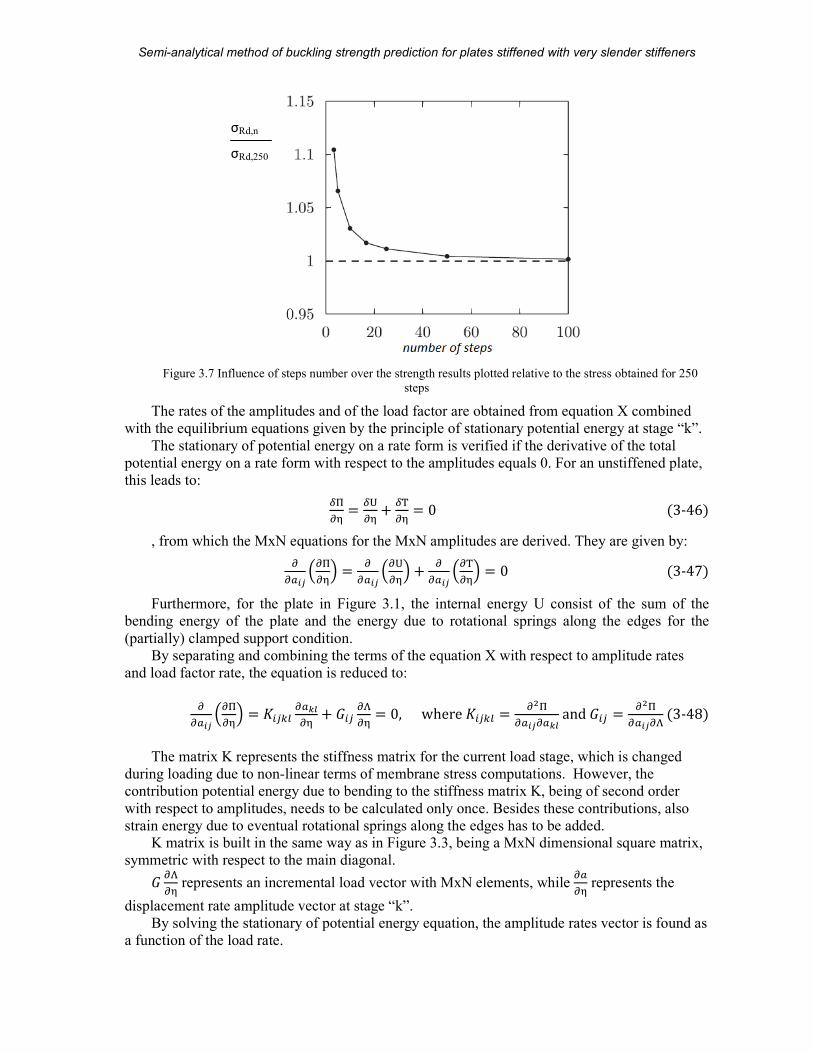
previous stage “k” as: ��?i�� � ��?i + "-.Ak"¶ Δη �3-44�Λi�� � Λi + "�k"¶ Δη �3-45�As it can be noticed, the magnitude of the arc-length parameter influences directly the
increase of the load factor. Because the load factor is just a multiplier of the actual load, which is
a variable, the arc-length parameter must be chosen inversely proportional to the later one, such
that the load increases slowly. Therefore, disregarding the magnitude of the initial load, the
number of steps will be approximately the same. For current project, a value between 2 and 5
divided by the initial stress has been found to give satisfactory results, leading to approximate
100 load incrementing steps before reaching the strength criteria. In the graph below it can be
clearly seen that with that value, the results converge to the results obtained with using 250 steps.
Semi-analytical method of buckling strength prediction for plates stiffened with very slender stiffeners
MSc Thesis 25 (104) A.D. Beju
Figure 3.7 Influence of steps number over the strength results plotted relative to the stress obtained for 250
steps
The rates of the amplitudes and of the load factor are obtained from equation X combined
with the equilibrium equations given by the principle of stationary potential energy at stage “k”.
The stationary of potential energy on a rate form is verified if the derivative of the total
potential energy on a rate form with respect to the amplitudes equals 0. For an unstiffened plate,
this leads to:
¼½"¶ � ¼¾"¶ + ¼¿"¶ � 0 �3-46�, from which the MxN equations for the MxN amplitudes are derived. They are given by:
""-.A "½"¶� � ""-.A "¾"¶� + ""-.A "¿"¶� � 0 �3-47�Furthermore, for the plate in Figure 3.1, the internal energy U consist of the sum of the
bending energy of the plate and the energy due to rotational springs along the edges for the
(partially) clamped support condition.
By separating and combining the terms of the equation X with respect to amplitude rates
and load factor rate, the equation is reduced to:
""-.A "½"¶� � 6�?ij "-kl"¶ + W�? "�"¶ � 0,where6�?ij � "#½"-.A"-klandW�? � "#½"-.A"��3-48�
The matrix K represents the stiffness matrix for the current load stage, which is changed
during loading due to non-linear terms of membrane stress computations. However, the
contribution potential energy due to bending to the stiffness matrix K, being of second order
with respect to amplitudes, needs to be calculated only once. Besides these contributions, also
strain energy due to eventual rotational springs along the edges has to be added. K matrix is built in the same way as in Figure 3.3, being a MxN dimensional square matrix,
symmetric with respect to the main diagonal. W "�"¶ represents an incremental load vector with MxN elements, while "-"¶ represents the
displacement rate amplitude vector at stage “k”.
By solving the stationary of potential energy equation, the amplitude rates vector is found as
a function of the load rate.
σRd,n
σRd,250
Semi-analytical method of buckling strength prediction for plates stiffened with very slender stiffeners
MSc Thesis 26 (104) A.D. Beju
"-kl"¶ � "�"¶6�?ijT� W�? � "�"¶ &ij �3-49�
, where &ij � 6�?ijT� W�? represents the displacement amplitudes’ rates normalized to the load
rate.
By inserting equation 3-49 into equation 3-43, the load rate parameter at stage “k” can be
found as: "�"¶� p� + ∑ ∑ &�? J?������ q � � �3-50�"�k"¶ � ± coc#�∑ ∑ À.Ak #ÁAÂÃÄ.ÂÃ
�3-51�The positive or negative value of the load rate is given by the smoothest evolution in the
equilibrium path in Figure 3.6. On a graphic, geometrically, this is satisfied by having the
absolute angle between the tangents of the current state “k” and previous state “k-1” smaller than
90˚. In order for this to be valid, the following criterion must be satisfied [5]:
∑ ∑ "�k"¶ ÅÀ.Ak Æ}.AkÇÃÆÈc# + "�kÇÃ"¶ É > 0J?������ �3-52�After finding the load factor rate, the amplitude rates are computed using XX, and further
on, the amplitudes and load factor at the next stage is obtained through equations x and x
respectively.
As stated, the internal strain energy consists of the contributions of the bending energy, the
membrane strain energy: U��(\ + �(� �3-53�
The potential energy due to membrane stretching of the middle plane is dependent on the
second order deformations which are obtained through Airy’s stress function defined in chapter
3.3.3. It reads:
�(\ � c � � � e "#x"H# + "#x"I#� − 2�1 + V� t"#x"H# "#x"I# − "#x"H"I� zf�%�% &F &G (3-54)
Being a function of the stress value at a certain stage, it needs to be calculated at every stage
“k”. This is one of the most time consuming computational efforts of the method.
The potential energy due to bending about the middle plane of the plate is given as:
�(� � � � �cd /��TU#� ∗ e "#$"H# + "#$"I#� − 2�1 − V� "#$"H# "#$"I# − "#$"H"I� f�%�% &F &G �3-55�Since the values are already computed during CBL as in 3.2, for saving computational
efforts, the K matrix will be initiated as the stiffness matrix in CBL. The energy for a (partially) clamped edge has also been computed in 3.2.1 and will be used in the calculations. It is calculate
as:
�)gc � � � +' "$"�� &0'�h (3-56)
The potential energy due to external loading at a certain stage “k” is given by:
3 � Λi � � c eNH% "$"H� NI% "$"I� + 2QHI "$"H ∗ "$"If &G &F�%�% �3-57�
Semi-analytical method of buckling strength prediction for plates stiffened with very slender stiffeners
MSc Thesis 27 (104) A.D. Beju
As it can be noticed, the total potential energy will result in a function of the amplitudes and
of the load factor. Furthermore, due to membrane energy, it will be of fourth order with respect
to amplitudes. Therefore, the derivations will be done incrementally, using the amplitudes of the
previous stage “k-1”. After analytical evaluation of the integrals and their derivatives with
respect to the amplitudes and load factor, the elements of the G vector for a constant biaxial
loaded plate at a stage k read:
W�?i � � ∗ Ë ∗ u~^∗�∗�#/∗� + uy^∗�∗?#/∗� � ∗ p��?iT� + n�?q �3-58�The K matrix consists of the derivatives of the bending and membrane energies, as well the
derivatives of the external load.
6�?�?�,(j-c� � 2 ∗ �∗cd� ∗��TU#� ∗ �¬∗�∗�Ì ∗ e ��� + ?�� f �3-59�
6�?�?\,(j-c� � �¬∗�∗�∗c/∗� ∗ ·∑ ∑ t"ÍwÎ"-.A �\�Ï + "ÍwÎÏ"-.A �\�z ∗ e \� � + ��� f J��% �\�% +2∑ t"Íw^"-.A �\%Ï + "Íw^Ï"-.A �\%z ∗ \� �/ J\�% + 2∑ t"Í̂ Î"-.A �%�Ï + "Í̂ ÎÏ"-.A �%�z ∗ ���/ J��% z �3-60�6�?�?D�Hc � Λi ∗ � ∗ Ë ∗ u~^∗�∗�#/∗� + uy^∗�∗?#/∗� � �3-61�
Finally, the K matrix reads:
6�?�? � 6�?�?�,(j-c� + 6�?�?\,(j-c� + 6�?�?D�Hc (3-62)
3.4 Eurocode procedure [1]
Eurocode EN 1993-1-5 presents various methods of analyzing the failure of a plate
including stability verifications. Two of them are chosen and presented here, namely: the
effective width method and the reduced stress method applied together with annex B. While the
former one is limited with respect to plates geometries, the latter one allows for more cases to be
analyzed.
3.4.1 Effective width method
The effective width method for plate buckling check is presented in sections 4, 5 and 6
where the plate is checked separately for direct stress, shear stress and transverse force
respectively. In section 7 the combined effects of these stresses are checked through interaction
formulae.
As the name states, the method is using a smaller effective area for the plate, considering
that its slender parts of the cross-section are inactive. For a simple plate, this reduced to finding a
reduction factor Ð representing the amount of effective area of the cross section with respect to
the total cross sectional area.
In function of its dimension and loading conditions, the behavior of the plate can be
represented by plate buckling, column buckling or a combined interaction of the two.
In order to compute the critical plate buckling stress, the Euler plate buckling stresses are
computed for the two directions. For the plate in fig. 7, they read:
Semi-analytical method of buckling strength prediction for plates stiffened with very slender stiffeners
MSc Thesis 28 (104) A.D. Beju
N�,H � �#�c#� ��TU#��# �3-63�N�,I � �#�c#� ��TU#��# �3-64�
This load needs to be reduced by a buckling coefficient according to orthotropic plate
theory, which, for a simple rectangular plate loaded with a constant stress equals:
+u,( � �� + ��� �3-65�Therefore, the critical plate buckling loads are: N�),(,H � +u,(N�,H��&N�),(,I � +u,(N�,I �3-66�Relative plate slenderness is obtained, which gives a first impression about how susceptible
to plate buckling the plate is. For the two directions, they are defined as is defined as: λ®(,H � o Ñ´uÒ ,�,~��&λ®(,I � o Ñ´uÒ ,�,y �3-67�
Since the plate is considered simply supported along all edges, the reduction factor is
computed according Section 4.4 of EC1993-1-5, for internal compression elements. It reads:
Ð � �1���λ®( ≤ 0.5 + Ó0.085 − 0.055Ôª«�T%.%ÕÕ�m�Ö�ª«�# ≤ 1���λ®( > 0.5 + Ó0.085 − 0.055Ô � �3-68�
The critical column buckling stresses are the Euler stresses calculated in the perpendicular
direction:
N�),�,H � N�,I � �#�c#� ��TU#��# �3-69�N�),�,I � N�,H � �#�c#� ��TU#��# �3-70�
In order to obtain the reduction factor for column buckling, the procedure in EN1993-1-1 is
used. The relative slenderness for the column is obtained as for the plate, namely: λ®�,H � o Ñ´uÒ ,�,~��&λ®�,I � o Ñ´uÒ ,�,y �3-71�
However, an intermediary step is taken, unlike in the plate buckling, for calculating the
factor Φ, a factor which relates the relative slenderness of the plate to imperfection factor for a
certain buckling curve. It reads:
Φ� � 0.5 1 + αpλ®�,� − 0.2q + λ®�,� �, where α=0.21 (buckling curve a is considered [ref.
4.5.4(5) of EN1993-1-5] ).
The “i” subscription refers to x, respectively y direction.
The buckling reduction factor is therefore defined as
Semi-analytical method of buckling strength prediction for plates stiffened with very slender stiffeners
MSc Thesis 29 (104) A.D. Beju
Ù�,� � �Ú.�oÚ.#Tª«Ò,.# ≤ 1 �3-72�
The final reduction factor is obtained by interpolating between the plate and column buckling reduction factors as it follows:
Û� � uÒ ,�,.uÒ ,Ò,. − 1n��0 ≤ Û� ≤ 1 �3-73�Ð� � pÐ(,� − Ù�,�q ∗ Û� ∗ �2 − Û�� + Ù�,� �3-74�
Subsequently, the capacity of the plate is determined as:
NÜÀ,� � Ýy�Äà ∗ Ð� �3-75�
3.4.2 Reduced stress method
The reduced stress method is presented in detail in Chapter 4.6 for a stiffened plate, being
also valid for the unstiffened plate.
3.5 Finite Element Analysis
For comparison, the plate is also modeled in ANSYS and SCIA engineer.
In ANSYS, shell281 elements are used with very fine smart size mesh (level 1) [19]. In
SCIA engineer has been observed that by decreasing the mesh size, the results converge towards
the ones obtained using ANSYS and current method. The SCIA engineer analyses are used for
validation purposes. Since in order to obtain accuracy, a very high number of elements need to
be used, which is translated to very high computational efforts, the SCIA engineer analyses are
left outside the comparisons of current work.
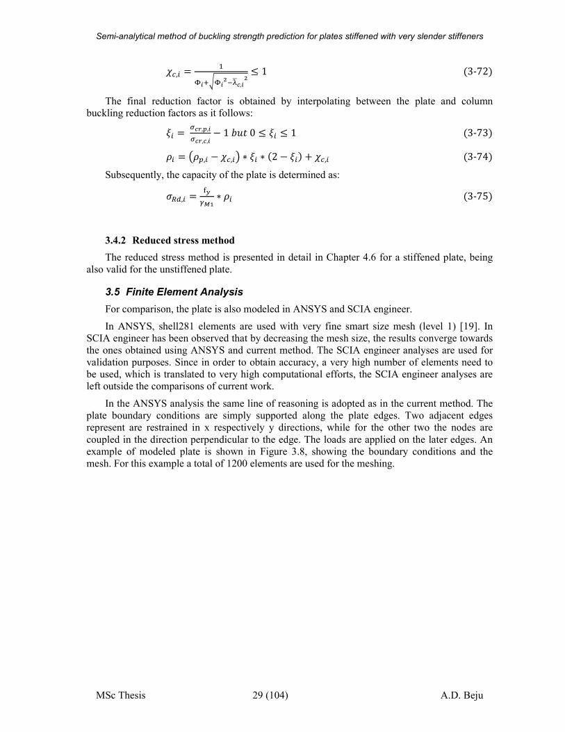
In the ANSYS analysis the same line of reasoning is adopted as in the current method. The
plate boundary conditions are simply supported along the plate edges. Two adjacent edges
represent are restrained in x respectively y directions, while for the other two the nodes are
coupled in the direction perpendicular to the edge. The loads are applied on the later edges. An
example of modeled plate is shown in Figure 3.8, showing the boundary conditions and the
mesh. For this example a total of 1200 elements are used for the meshing.
Semi-analytical method of buckling strength prediction
MSc Thesis
Figure
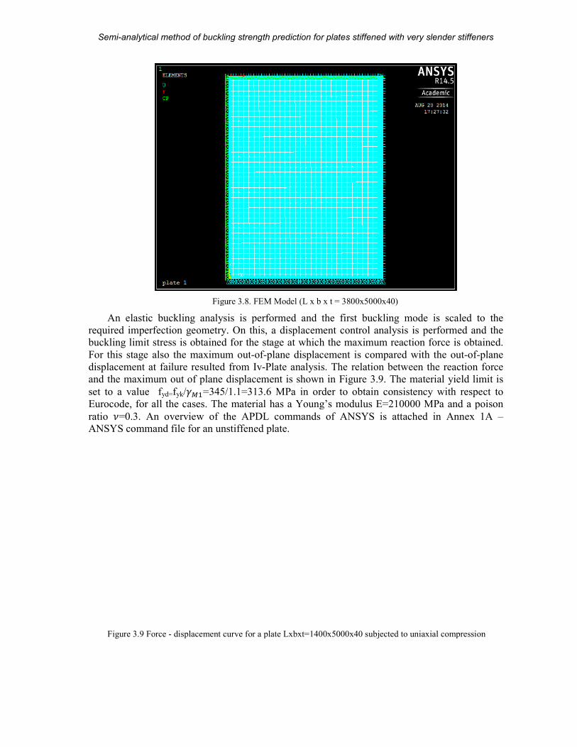
An elastic buckling analysis is performed and the first
required imperfection geometry. On thbuckling limit stress is obtained for
For this stage also the maximum out
displacement at failure resulted from
and the maximum out of plane displacement is shown in
set to a value fyd=fyk/S��=345/1.1=313.6 MPa in order to obtain consi
Eurocode, for all the cases. The material has a Young’s modulus E=210000 MPa and a poison
ratio V=0.3. An overview of the APDL commands of ANSYS is attached in ANSYS command file for an unstiffened plate
Figure 3.9 Force - displacement curve for a plate Lxbxt=1400x5000x40 subjected to uniaxial compression
analytical method of buckling strength prediction for plates stiffened with very slender stiffeners
30 (104)
Figure 3.8. FEM Model (L x b x t = 3800x5000x40)
An elastic buckling analysis is performed and the first buckling mode is scaled to the
required imperfection geometry. On this, a displacement control analysis is performed and the buckling limit stress is obtained for the stage at which the maximum reaction force is obtained.
For this stage also the maximum out-of-plane displacement is compared with the out
resulted from Iv-Plate analysis. The relation between the reaction force
and the maximum out of plane displacement is shown in Figure 3.9. The material yield limit is
=345/1.1=313.6 MPa in order to obtain consistency with respect to
Eurocode, for all the cases. The material has a Young’s modulus E=210000 MPa and a poison
An overview of the APDL commands of ANSYS is attached in unstiffened plate.
displacement curve for a plate Lxbxt=1400x5000x40 subjected to uniaxial compression
plates stiffened with very slender stiffeners
A.D. Beju
mode is scaled to the
is, a displacement control analysis is performed and the reaction force is obtained.
plane displacement is compared with the out-of-plane
The relation between the reaction force
The material yield limit is
stency with respect to
Eurocode, for all the cases. The material has a Young’s modulus E=210000 MPa and a poison
An overview of the APDL commands of ANSYS is attached in Annex 1A –
displacement curve for a plate Lxbxt=1400x5000x40 subjected to uniaxial compression

Semi-analytical method of buckling strength prediction for plates stiffened with very slender stiffeners
MSc Thesis 31 (104) A.D. Beju
3.6 Validation of the FEM results
3.6.1 The reference article
The article “Post-buckling strength of uniformly compressed plates” by Bakker et al. (2006)
[17] was used for validation of the FE model in ANSYS APDL (release 14.5.7). The geometry,
applied imperfection pattern, geometrical and material properties, theoretical critical loads and
non-linear results are shown in
Figure 3.10 Simply supported plate loaded in uniform compression (Bakker et al. 2006).
The critical elastic buckling load of a square plate in uniform compression can be
determined theoretically according to:
N�),(j-c� � +u,( �#�c#� ��TU#��# �3-76�, where E is the Young’s modulus, is the plate thickness, V is the Poisson constant and +u,(
is the width of the plate in the direction perpendicular to the direction of loading. The buckling
coefficient is equal to 4 for a square plate.
The elasto-plastic failure load including imperfections depends on the plate geometry, the
boundary conditions and the size and shape of the imperfection. Theoretical determination of
Semi-analytical method of buckling strength prediction for plates stiffened with very slender stiffeners
MSc Thesis 32 (104) A.D. Beju
this failure load is not straightforward. Therefore the non-linear curves in Figure 3.10 were used
for validation of the FE model presented in chapter 3.5.
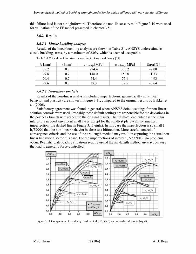
3.6.2 Results
3.6.2.1 Linear buckling analysis
Results of the linear buckling analysis are shown in Table 3-1. ANSYS underestimates
elastic buckling stress, by a maximum of 2.0%, which is deemed acceptable.
Table 3-1 Critical buckling stress according to Ansys and theory [17]
b [mm] t [mm] σcr,Ansys[MPa] σcr,theory[MPa] Error[%]
35.2 0.7 294.4 300.2 -2.00
49.8 0.7 148.0 150.0 -1.33
70.4 0.7 74.4 75.1 -0.93
99.6 0.7 37.3 37.5 -0.64
3.6.2.2 Non-linear analysis
Results of the non-linear analysis including imperfections, geometrically non-linear
behavior and plasticity are shown in Figure 3.11, compared to the original results by Bakker et
al. (2006).
Satisfactory agreement was found in general when ANSYS default settings for non-linear
solution controls were used. Probably these default settings are responsible for the deviations in
the postpeak branch with respect to the original results. The ultimate load, which is the main interest, is in good agreement in all cases except for the smallest plate with the smallest
imperfection (the dashed line in Figure 3.11-right). In this case the imperfection is so small ( b/5000�that the non-linear behavior is close to a bifurcation. More careful control of
convergence criteria and the use of the arc-length method may result in capturing the actual non-
linear behavior also for this case. For the imperfections of interest �>b/200�, no problems
occur. Realistic plate loading situations require use of the arc-length method anyway, because
the load is generally force-controlled.
Figure 3.11 Comparison of results by Bakker et al. [17] (left) and reproduced results (right).
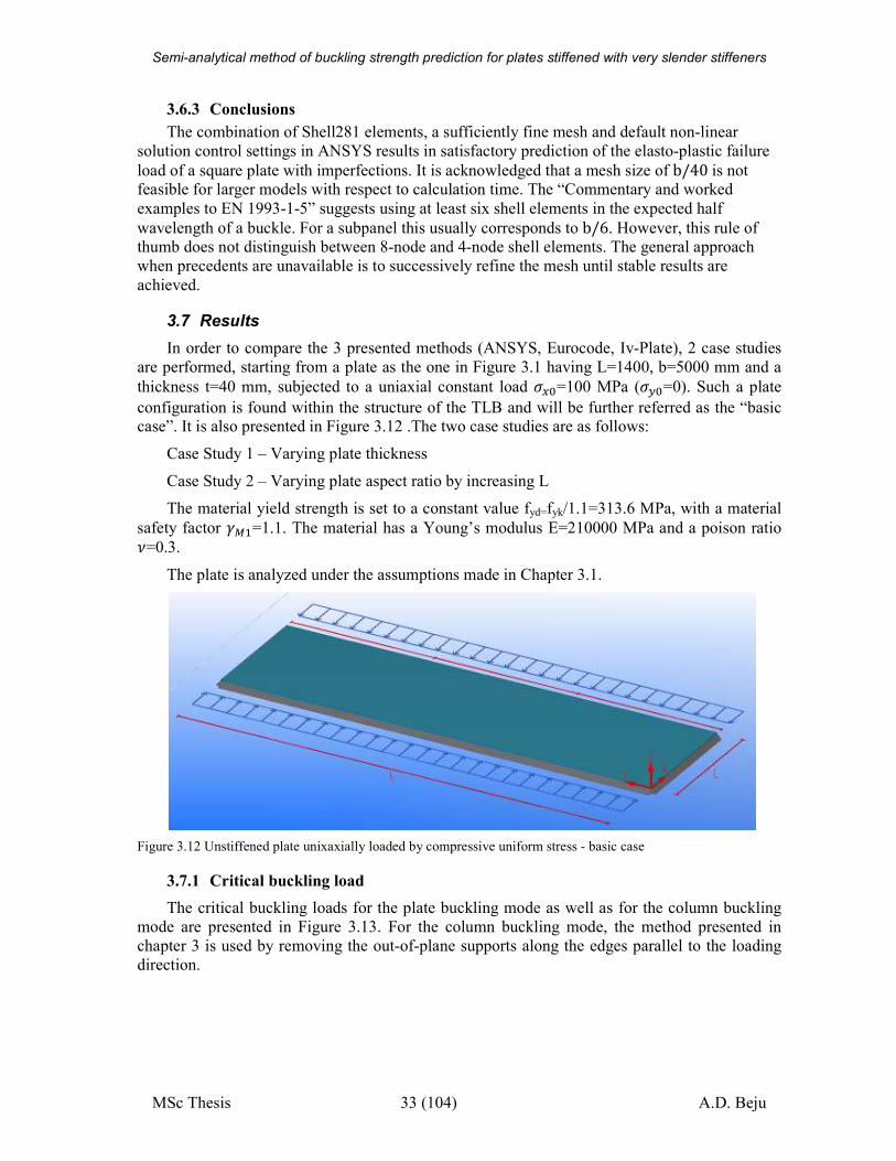
Semi-analytical method of buckling strength prediction for plates stiffened with very slender stiffeners
MSc Thesis 33 (104) A.D. Beju
3.6.3 Conclusions
The combination of Shell281 elements, a sufficiently fine mesh and default non-linear
solution control settings in ANSYS results in satisfactory prediction of the elasto-plastic failure
load of a square plate with imperfections. It is acknowledged that a mesh size of b/40is not feasible for larger models with respect to calculation time. The “Commentary and worked
examples to EN 1993-1-5” suggests using at least six shell elements in the expected half
wavelength of a buckle. For a subpanel this usually corresponds to b/6. However, this rule of thumb does not distinguish between 8-node and 4-node shell elements. The general approach
when precedents are unavailable is to successively refine the mesh until stable results are
achieved.
3.7 Results
In order to compare the 3 presented methods (ANSYS, Eurocode, Iv-Plate), 2 case studies
are performed, starting from a plate as the one in Figure 3.1 having L=1400, b=5000 mm and a
thickness t=40 mm, subjected to a uniaxial constant load NH%=100 MPa (NI%=0). Such a plate
configuration is found within the structure of the TLB and will be further referred as the “basic case”. It is also presented in Figure 3.12 .The two case studies are as follows:
Case Study 1 – Varying plate thickness
Case Study 2 – Varying plate aspect ratio by increasing L
The material yield strength is set to a constant value fyd=fyk/1.1=313.6 MPa, with a material
safety factor S��=1.1. The material has a Young’s modulus E=210000 MPa and a poison ratio V=0.3.
The plate is analyzed under the assumptions made in Chapter 3.1.
Figure 3.12 Unstiffened plate unixaxially loaded by compressive uniform stress - basic case
3.7.1 Critical buckling load
The critical buckling loads for the plate buckling mode as well as for the column buckling
mode are presented in Figure 3.13. For the column buckling mode, the method presented in
chapter 3 is used by removing the out-of-plane supports along the edges parallel to the loading
direction.
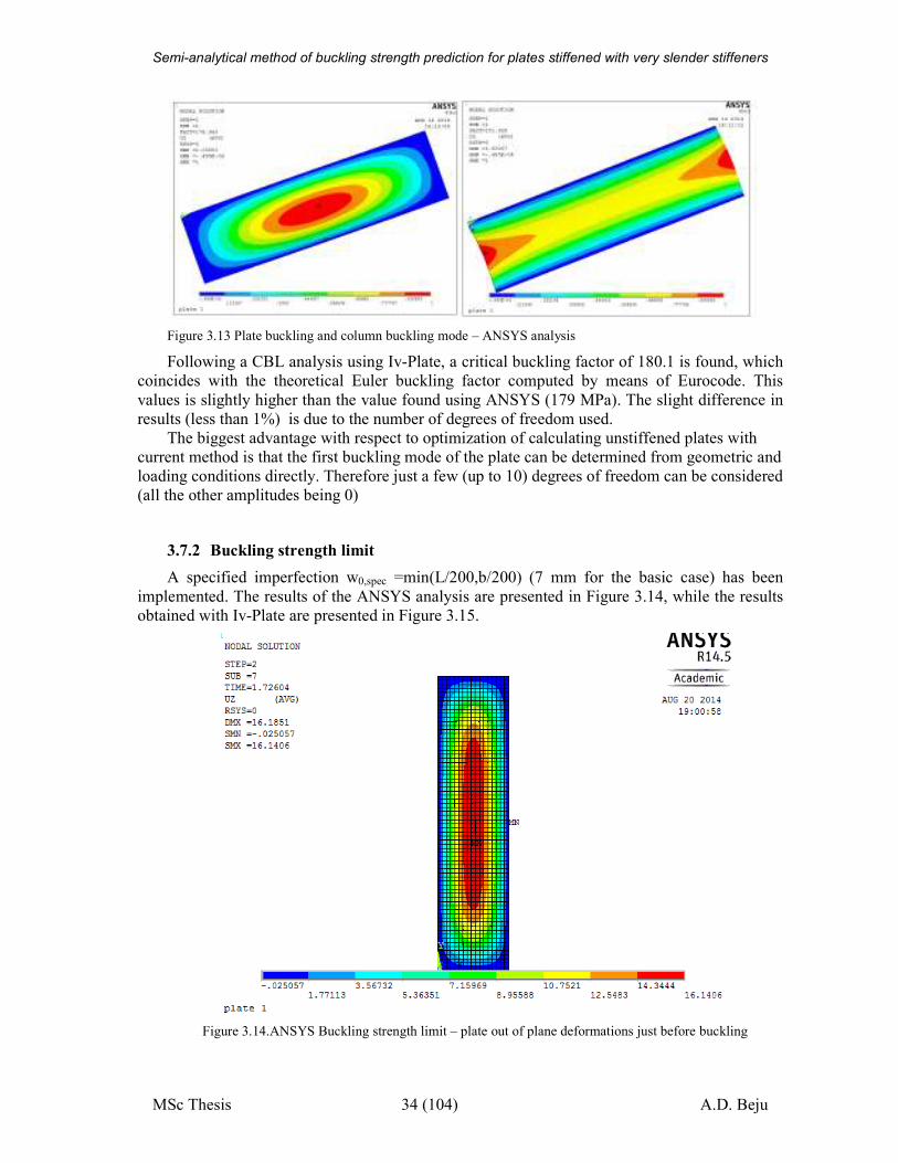
Semi-analytical method of buckling strength prediction for plates stiffened with very slender stiffeners
MSc Thesis 34 (104) A.D. Beju
Figure 3.13 Plate buckling and column buckling mode – ANSYS analysis
Following a CBL analysis using Iv-Plate, a critical buckling factor of 180.1 is found, which
coincides with the theoretical Euler buckling factor computed by means of Eurocode. This
values is slightly higher than the value found using ANSYS (179 MPa). The slight difference in
results (less than 1%) is due to the number of degrees of freedom used.
The biggest advantage with respect to optimization of calculating unstiffened plates with
current method is that the first buckling mode of the plate can be determined from geometric and
loading conditions directly. Therefore just a few (up to 10) degrees of freedom can be considered
(all the other amplitudes being 0)
3.7.2 Buckling strength limit
A specified imperfection w0,spec =min(L/200,b/200) (7 mm for the basic case) has been
implemented. The results of the ANSYS analysis are presented in Figure 3.14, while the results
obtained with Iv-Plate are presented in Figure 3.15.
Figure 3.14.ANSYS Buckling strength limit – plate out of plane deformations just before buckling
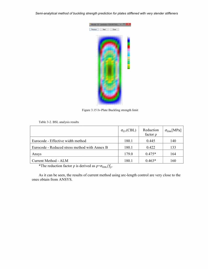
Semi-analytical method of buckling strength prediction
MSc Thesis
Figure
Table 3-2. BSL analysis results
Eurocode - Effective width method
Eurocode - Reduced stress method with Annex B
Ansys
Current Method - ALM
*The reduction factor ρ is derived as ρ=
As it can be seen, the results of current method using arc
ones obtain from ANSYS.
analytical method of buckling strength prediction for plates stiffened with very slender stiffeners
35 (104)
Figure 3.15 Iv-Plate Buckling strength limit
N²)(CBL) Reduction
factor ρ
Effective width method 180.1 0.445
Reduced stress method with Annex B 180.1 0.422
179.0 0.475*
180.1 0.463*
erived as ρ=Nj�\/�I.
As it can be seen, the results of current method using arc-length control are very
plates stiffened with very slender stiffeners
A.D. Beju
Reduction
factor ρ Nj�\[MPa]
140
133
0.475* 164
0.463* 160
length control are very close to the
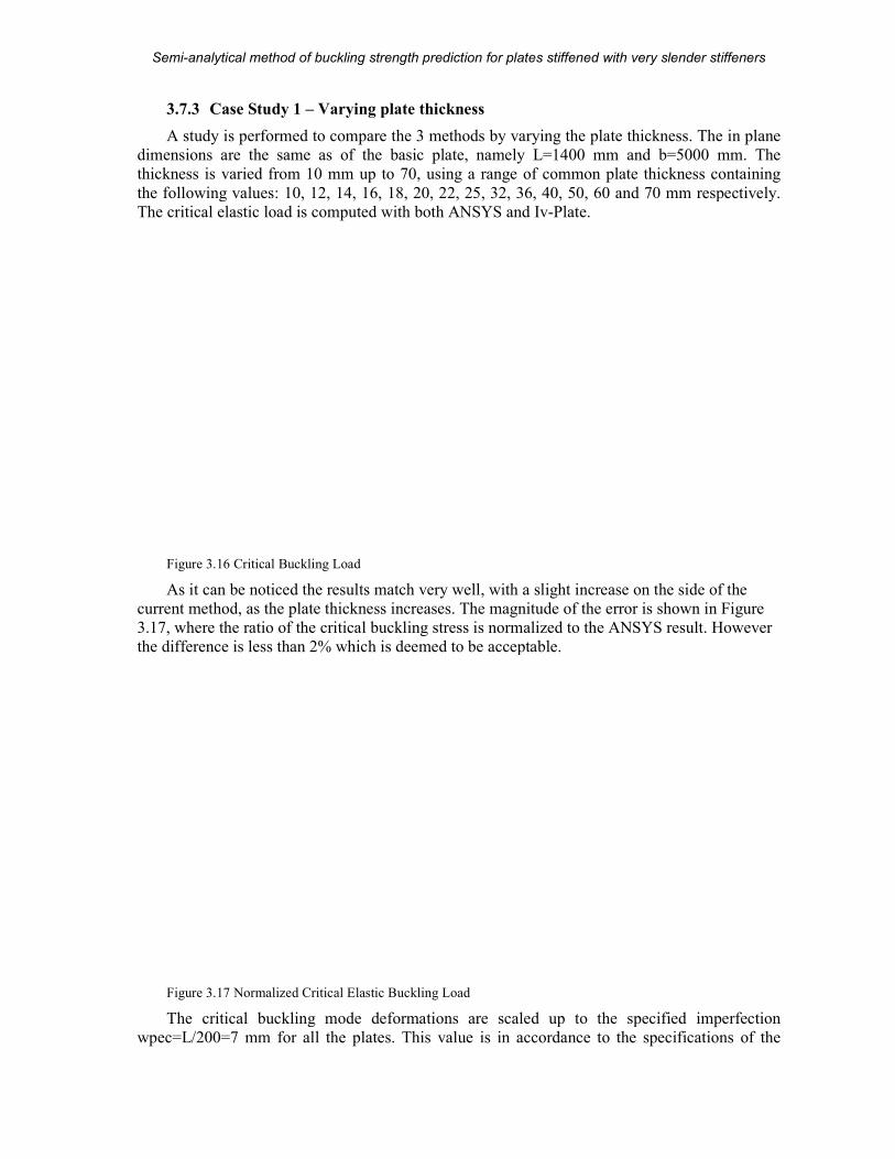
Semi-analytical method of buckling strength prediction
MSc Thesis
3.7.3 Case Study 1 – Varying plate thickness
A study is performed to compare the 3 methods by varying the
dimensions are the same as of the basic plate, namely L=1400 mm and b=5000 mm. The
thickness is varied from 10 mm up to 70, using a range of common plate thickness containing
the following values: 10, 12, 14, 16, 18, 20, 22, 2
The critical elastic load is computed with both ANSYS and
Figure 3.16 Critical Buckling Load
As it can be noticed the results match very well, with a
current method, as the plate thickness increases. The magnitude of the error is shown in
3.17, where the ratio of the critical buckling stress is normalized to the ANSYS re
the difference is less than 2% which is deemed to be acceptable.
Figure 3.17 Normalized Critical Elastic Buckling Load
The critical buckling mode deformations are scaled up to the specified im
wpec=L/200=7 mm for all the plates. This value is in accordance to the specifications of the
analytical method of buckling strength prediction for plates stiffened with very slender stiffeners
36 (104)
Varying plate thickness
A study is performed to compare the 3 methods by varying the plate thickness. The in plane
dimensions are the same as of the basic plate, namely L=1400 mm and b=5000 mm. The
mm up to 70, using a range of common plate thickness containing
the following values: 10, 12, 14, 16, 18, 20, 22, 25, 32, 36, 40, 50, 60 and 70 mm respectively.
The critical elastic load is computed with both ANSYS and Iv-Plate.
ad
As it can be noticed the results match very well, with a slight increase on the side of the
current method, as the plate thickness increases. The magnitude of the error is shown in
, where the ratio of the critical buckling stress is normalized to the ANSYS re
the difference is less than 2% which is deemed to be acceptable.
Normalized Critical Elastic Buckling Load
The critical buckling mode deformations are scaled up to the specified im
wpec=L/200=7 mm for all the plates. This value is in accordance to the specifications of the
plates stiffened with very slender stiffeners
A.D. Beju
plate thickness. The in plane
dimensions are the same as of the basic plate, namely L=1400 mm and b=5000 mm. The
mm up to 70, using a range of common plate thickness containing
5, 32, 36, 40, 50, 60 and 70 mm respectively.
slight increase on the side of the
current method, as the plate thickness increases. The magnitude of the error is shown in Figure
, where the ratio of the critical buckling stress is normalized to the ANSYS result. However
The critical buckling mode deformations are scaled up to the specified imperfection
wpec=L/200=7 mm for all the plates. This value is in accordance to the specifications of the
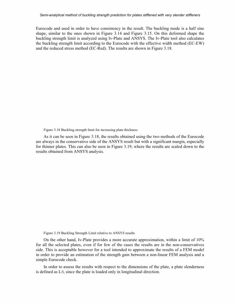
Semi-analytical method of buckling strength prediction
MSc Thesis
Eurocode and used in order to have consistency in the result. The buckling mode is a half sine
shape, similar to the ones shown in
buckling strength limit is analyzed using
the buckling strength limit accor
and the reduced stress method (EC
Figure 3.18 Buckling strength limit for increasing plate thickness
As it can be seen in Figure 3
are always in the conservative side of the ANSYS result but with a significant
for thinner plates. This can also be seen in
results obtained from ANSYS analysis.
Figure 3.19 Buckling Strength Limit relative to ANSYS results
On the other hand, Iv-Plate
for all the selected plates, even if for few of the cases the results are in the non
side. This is acceptable however for a tool intended to approximate the results of a FEM model
in order to provide an estimation of the strength
simple Eurocode check.
In order to assess the results with respect to the dimen
is defined as L/t, since the plate is loaded only in longitudinal direction.
analytical method of buckling strength prediction for plates stiffened with very slender stiffeners
37 (104)
Eurocode and used in order to have consistency in the result. The buckling mode is a half sine
shape, similar to the ones shown in Figure 3.14 and Figure 3.15. On this deformed shape the
buckling strength limit is analyzed using Iv-Plate and ANSYS. The Iv-Plate tool also calculates
the buckling strength limit according to the Eurocode with the effective width method (EC
and the reduced stress method (EC-Red). The results are shown in Figure 3.18.
ngth limit for increasing plate thickness
3.18, the results obtained using the two methods of the Eurocode
are always in the conservative side of the ANSYS result but with a significant margin, especially
for thinner plates. This can also be seen in Figure 3.19, where the results are scaled down to the
results obtained from ANSYS analysis.
Buckling Strength Limit relative to ANSYS results
provides a more accurate approximation, within a limit of 10%
, even if for few of the cases the results are in the non
acceptable however for a tool intended to approximate the results of a FEM model
in order to provide an estimation of the strength gain between a non-linear FEM analysis and a
In order to assess the results with respect to the dimensions of the plate, a plate slenderness
is defined as L/t, since the plate is loaded only in longitudinal direction.
plates stiffened with very slender stiffeners
A.D. Beju
Eurocode and used in order to have consistency in the result. The buckling mode is a half sine
. On this deformed shape the
tool also calculates
ding to the Eurocode with the effective width method (EC-EW)
, the results obtained using the two methods of the Eurocode
margin, especially
, where the results are scaled down to the
, within a limit of 10%
, even if for few of the cases the results are in the non-conservatives
acceptable however for a tool intended to approximate the results of a FEM model
linear FEM analysis and a
sions of the plate, a plate slenderness
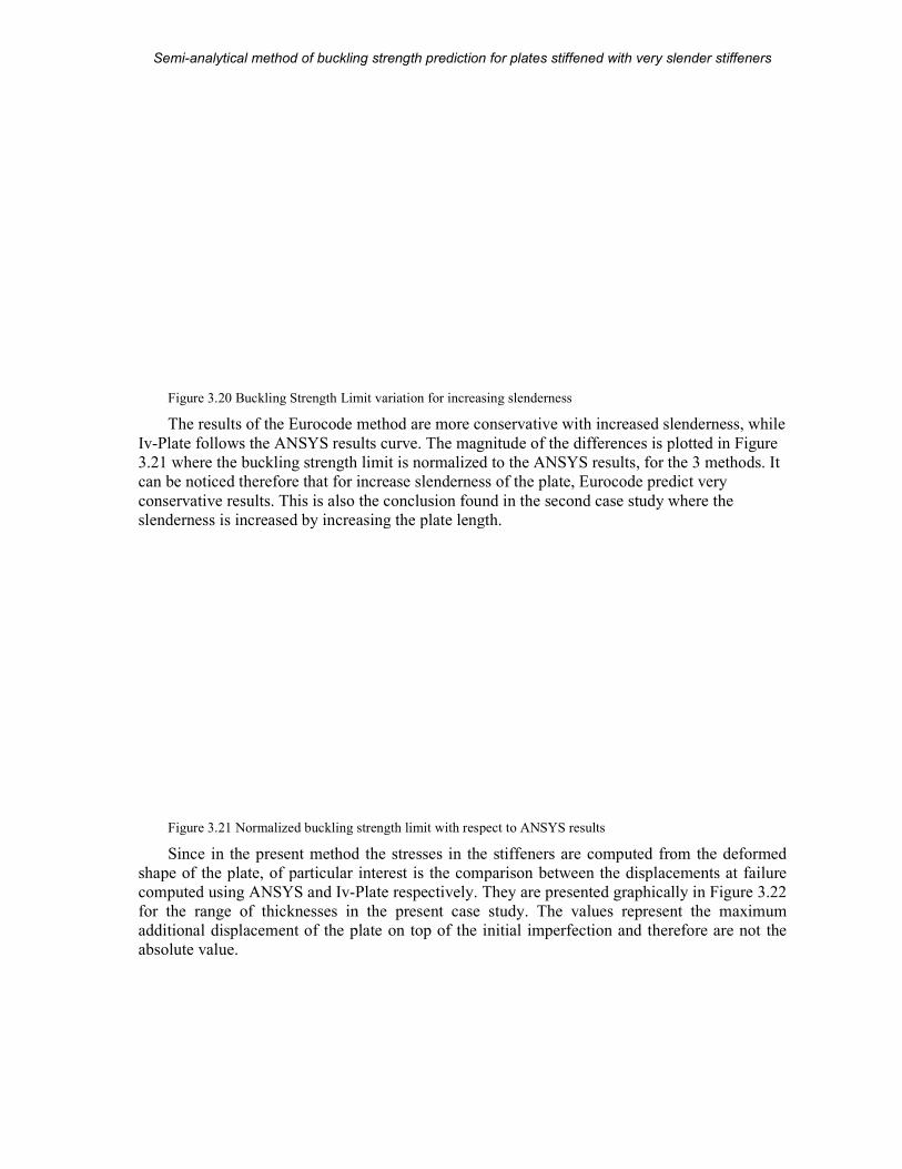
Semi-analytical method of buckling strength prediction
MSc Thesis
Figure 3.20 Buckling Strength Limit variation for increasing slenderness
The results of the Eurocode method are more conservative with increased slenderness, while
Iv-Plate follows the ANSYS results curve. The
3.21 where the buckling strength limit is
can be noticed therefore that for increase slenderness of the plate, Eurocode predict very
conservative results. This is also the conclusion found in the second case study
slenderness is increased by increasing the plate length.
Figure 3.21 Normalized buckling strength limit with respect to ANSYS results
Since in the present method the stresses in the stiffeners are computed from the deformed
shape of the plate, of particular interest is the comparison between the displacements at failure
computed using ANSYS and Iv-Plate
for the range of thicknesses in the present case study. The values represent the maximum
additional displacement of the plate on top of the initial imperfection and therefore
absolute value.
analytical method of buckling strength prediction for plates stiffened with very slender stiffeners
38 (104)
Buckling Strength Limit variation for increasing slenderness
the Eurocode method are more conservative with increased slenderness, while
follows the ANSYS results curve. The magnitude of the differences is plotted in
where the buckling strength limit is normalized to the ANSYS results, for the 3 methods. It
can be noticed therefore that for increase slenderness of the plate, Eurocode predict very
conservative results. This is also the conclusion found in the second case study where the
reased by increasing the plate length.
Normalized buckling strength limit with respect to ANSYS results
Since in the present method the stresses in the stiffeners are computed from the deformed
shape of the plate, of particular interest is the comparison between the displacements at failure
Plate respectively. They are presented graphically in
nesses in the present case study. The values represent the maximum
additional displacement of the plate on top of the initial imperfection and therefore
plates stiffened with very slender stiffeners
A.D. Beju
the Eurocode method are more conservative with increased slenderness, while
plotted in Figure
normalized to the ANSYS results, for the 3 methods. It
can be noticed therefore that for increase slenderness of the plate, Eurocode predict very
where the
Since in the present method the stresses in the stiffeners are computed from the deformed
shape of the plate, of particular interest is the comparison between the displacements at failure
respectively. They are presented graphically in Figure 3.22
nesses in the present case study. The values represent the maximum
additional displacement of the plate on top of the initial imperfection and therefore are not the
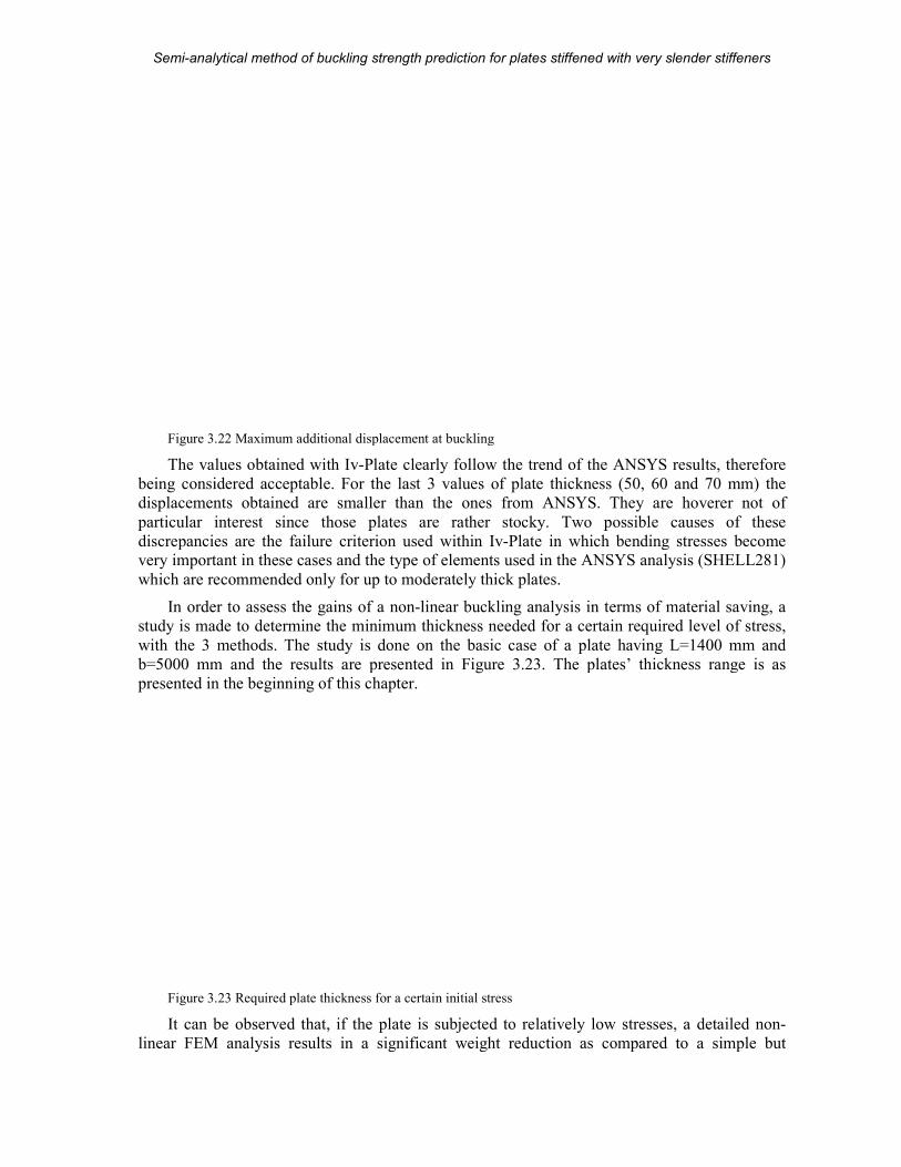
Semi-analytical method of buckling strength prediction
MSc Thesis
Figure 3.22 Maximum additional displacement at buckling
The values obtained with Iv
being considered acceptable. For the last 3 values of plate thickness (50, 60 and 70 mm) the
displacements obtained are smaller than
particular interest since those plates are rather stocky. Two possible causes of these
discrepancies are the failure criterion used within very important in these cases and the type of elements used in the ANSYS analysis (SHELL281)
which are recommended only for up to moderately thick plates.
In order to assess the gains of a non
study is made to determine the minimu
with the 3 methods. The study is done on the basic case of a plate having L=1400 mm and
b=5000 mm and the results are presented in
presented in the beginning of this chapter.
Figure 3.23 Required plate thickness for a certain initial stress
It can be observed that, if the plate is subjected to relatively low stresses, a detailed
linear FEM analysis results in a significant weight reduction as compared to a simple but
analytical method of buckling strength prediction for plates stiffened with very slender stiffeners
39 (104)
tional displacement at buckling
Iv-Plate clearly follow the trend of the ANSYS results, therefore
For the last 3 values of plate thickness (50, 60 and 70 mm) the
displacements obtained are smaller than the ones from ANSYS. They are hoverer not of
particular interest since those plates are rather stocky. Two possible causes of these
discrepancies are the failure criterion used within Iv-Plate in which bending stresses become and the type of elements used in the ANSYS analysis (SHELL281)
which are recommended only for up to moderately thick plates.
In order to assess the gains of a non-linear buckling analysis in terms of material saving
study is made to determine the minimum thickness needed for a certain required level of stress,
with the 3 methods. The study is done on the basic case of a plate having L=1400 mm and
b=5000 mm and the results are presented in Figure 3.23. The plates’ thickness range
presented in the beginning of this chapter.
Required plate thickness for a certain initial stress
It can be observed that, if the plate is subjected to relatively low stresses, a detailed
linear FEM analysis results in a significant weight reduction as compared to a simple but
plates stiffened with very slender stiffeners
A.D. Beju
clearly follow the trend of the ANSYS results, therefore
For the last 3 values of plate thickness (50, 60 and 70 mm) the
the ones from ANSYS. They are hoverer not of
particular interest since those plates are rather stocky. Two possible causes of these
in which bending stresses become and the type of elements used in the ANSYS analysis (SHELL281)
linear buckling analysis in terms of material saving, a
m thickness needed for a certain required level of stress,
with the 3 methods. The study is done on the basic case of a plate having L=1400 mm and
The plates’ thickness range is as
It can be observed that, if the plate is subjected to relatively low stresses, a detailed non-
linear FEM analysis results in a significant weight reduction as compared to a simple but
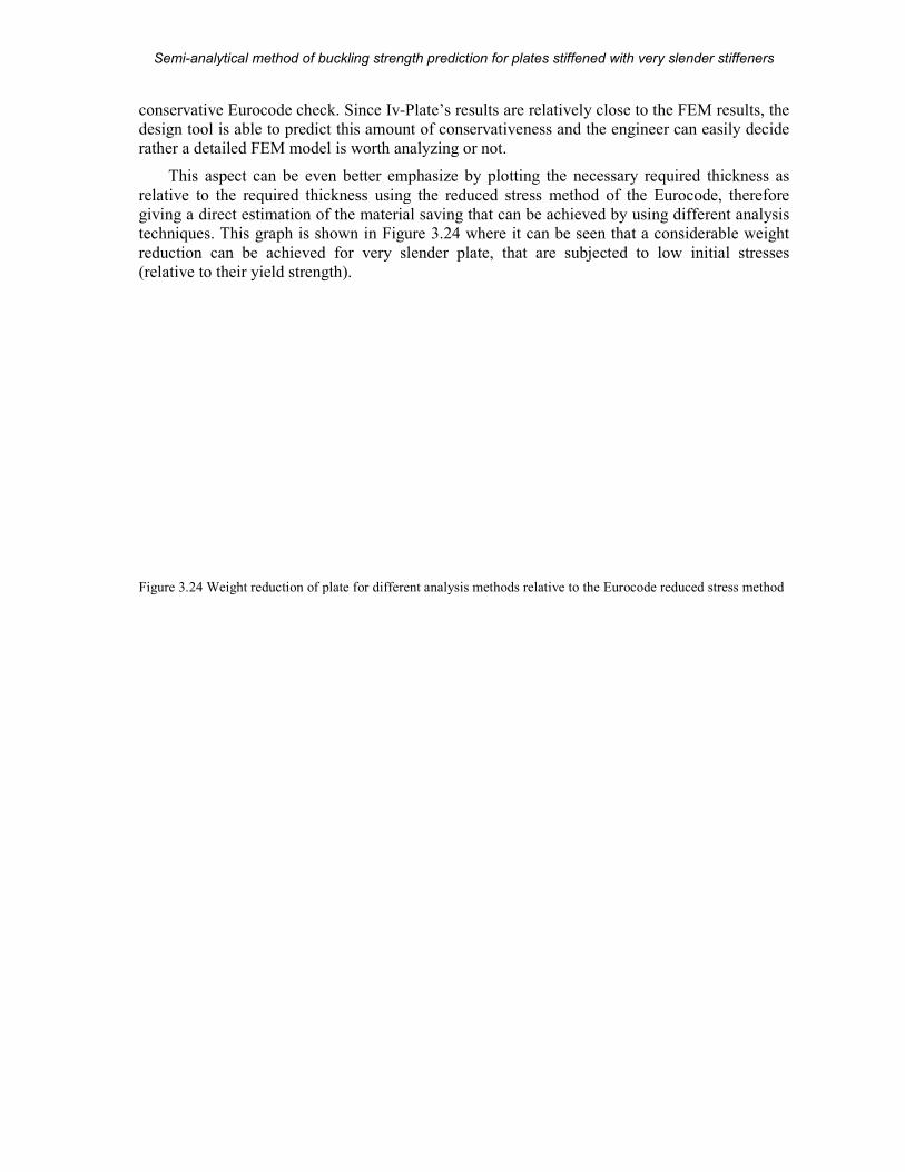
Semi-analytical method of buckling strength prediction
MSc Thesis
conservative Eurocode check. Since
design tool is able to predict this amount of conservativeness
rather a detailed FEM model is worth analyzing or not.
This aspect can be even better emphasize by plotting the necessary required thickness as
relative to the required thickness using the reduced stress method of the Eu
giving a direct estimation of the material saving that can be achieved by using different analysis techniques. This graph is shown in
reduction can be achieved for very slender plate, that are subjected to low initial stresses
(relative to their yield strength).
Figure 3.24 Weight reduction of plate for different analysis methods relative to the Eurocode r
analytical method of buckling strength prediction for plates stiffened with very slender stiffeners
40 (104)
conservative Eurocode check. Since Iv-Plate’s results are relatively close to the FEM results, the
design tool is able to predict this amount of conservativeness and the engineer can easily decide
rather a detailed FEM model is worth analyzing or not.
This aspect can be even better emphasize by plotting the necessary required thickness as
relative to the required thickness using the reduced stress method of the Eurocode, therefore
giving a direct estimation of the material saving that can be achieved by using different analysis techniques. This graph is shown in Figure 3.24 where it can be seen that a considerable weight
chieved for very slender plate, that are subjected to low initial stresses
of plate for different analysis methods relative to the Eurocode reduced stress method
plates stiffened with very slender stiffeners
A.D. Beju
’s results are relatively close to the FEM results, the
and the engineer can easily decide
This aspect can be even better emphasize by plotting the necessary required thickness as
rocode, therefore
giving a direct estimation of the material saving that can be achieved by using different analysis where it can be seen that a considerable weight
chieved for very slender plate, that are subjected to low initial stresses
educed stress method
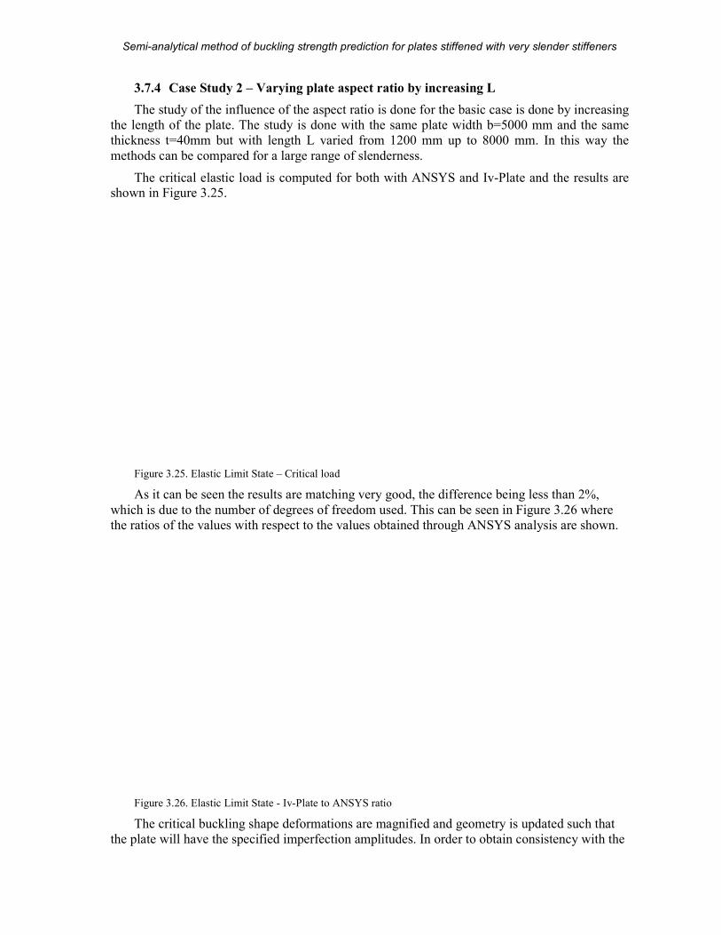
Semi-analytical method of buckling strength prediction
MSc Thesis
3.7.4 Case Study 2 – Varying plate aspect ratio by increasing L
The study of the influence of the
the length of the plate. The study is done with the same plate width b=5000 mm
thickness t=40mm but with length L varied from 1200 mm up to 8000 mm. In this way the
methods can be compared for a large range of slenderness.
The critical elastic load is computed for both with ANSYS and shown in Figure 3.25.
Figure 3.25. Elastic Limit State –
As it can be seen the results are matching very good, the
which is due to the number of degrees of freedom used.
the ratios of the values with respect to the values obtained through ANSYS analysis are
Figure 3.26. Elastic Limit State - Iv
The critical buckling shape deformations are magnified and geometry is updated such that
the plate will have the specified imperfection amplitudes. In order to obtain consistency with t
analytical method of buckling strength prediction for plates stiffened with very slender stiffeners
41 (104)
Varying plate aspect ratio by increasing L
The study of the influence of the aspect ratio is done for the basic case is done by increasing
the length of the plate. The study is done with the same plate width b=5000 mm
thickness t=40mm but with length L varied from 1200 mm up to 8000 mm. In this way the
methods can be compared for a large range of slenderness.
The critical elastic load is computed for both with ANSYS and Iv-Plate and the results are
Critical load
As it can be seen the results are matching very good, the difference being less than 2%,
to the number of degrees of freedom used. This can be seen in Figure
ratios of the values with respect to the values obtained through ANSYS analysis are
Iv-Plate to ANSYS ratio
The critical buckling shape deformations are magnified and geometry is updated such that
the plate will have the specified imperfection amplitudes. In order to obtain consistency with t
plates stiffened with very slender stiffeners
A.D. Beju
is done by increasing
the length of the plate. The study is done with the same plate width b=5000 mm and the same
thickness t=40mm but with length L varied from 1200 mm up to 8000 mm. In this way the
and the results are
being less than 2%,
Figure 3.26 where
ratios of the values with respect to the values obtained through ANSYS analysis are shown.
The critical buckling shape deformations are magnified and geometry is updated such that
the plate will have the specified imperfection amplitudes. In order to obtain consistency with the
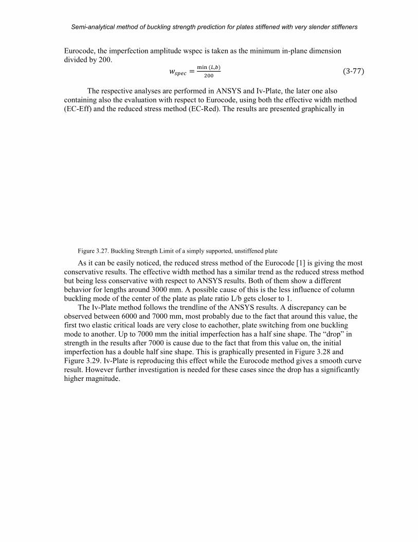
Semi-analytical method of buckling strength prediction
MSc Thesis
Eurocode, the imperfection amplitude wspec is taken as the minimum in
divided by 200.
The respective analyses are performed in ANSYS and
containing also the evaluation with respect to Eurocode
(EC-Eff) and the reduced stress method (EC
Figure 3.27. Buckling Strength Limit of a simply supported, unstiffened plate
As it can be easily noticed, the reduced stress method of the Eurocode [1] is giving the most
conservative results. The effective width method has a similar trend as the reduced stress method
but being less conservative with respect to ANSYS results. Both of them show a differen
behavior for lengths around 3000 mm. A possible cause of this is the less influence of column
buckling mode of the center of the plate as plate ratio L/b gets closer to 1.
The Iv-Plate method follows the trend
observed between 6000 and 7000 mm, most probably due to the fact that around this value, the
first two elastic critical loads are very close to eachother, plate switching from one buckling
mode to another. Up to 7000 mm the initial imperfection has a ha
strength in the results after 7000 is cause due to the fact that from this value on, the initial
imperfection has a double half sine shape
Figure 3.29. Iv-Plate is reproducing this effect while the Eurocode method gives a smooth curve
result. However further investigation is needed for these cases since the drop has a significantly
higher magnitude.
analytical method of buckling strength prediction for plates stiffened with very slender stiffeners
42 (104)
Eurocode, the imperfection amplitude wspec is taken as the minimum in-plane dimension
�'(�� � ßàá��,�� %% The respective analyses are performed in ANSYS and Iv-Plate, the later one also
the evaluation with respect to Eurocode, using both the effective
Eff) and the reduced stress method (EC-Red). The results are presented graphically in
. Buckling Strength Limit of a simply supported, unstiffened plate
iced, the reduced stress method of the Eurocode [1] is giving the most
The effective width method has a similar trend as the reduced stress method
but being less conservative with respect to ANSYS results. Both of them show a differen
behavior for lengths around 3000 mm. A possible cause of this is the less influence of column
buckling mode of the center of the plate as plate ratio L/b gets closer to 1.
method follows the trendline of the ANSYS results. A discrepancy can
observed between 6000 and 7000 mm, most probably due to the fact that around this value, the
first two elastic critical loads are very close to eachother, plate switching from one buckling
mode to another. Up to 7000 mm the initial imperfection has a half sine shape. The “drop” in
strength in the results after 7000 is cause due to the fact that from this value on, the initial
sine shape. This is graphically presented in Figure
is reproducing this effect while the Eurocode method gives a smooth curve
However further investigation is needed for these cases since the drop has a significantly
plates stiffened with very slender stiffeners
A.D. Beju
plane dimension
�3-77�, the later one also
width method
The results are presented graphically in
iced, the reduced stress method of the Eurocode [1] is giving the most
The effective width method has a similar trend as the reduced stress method
but being less conservative with respect to ANSYS results. Both of them show a different
behavior for lengths around 3000 mm. A possible cause of this is the less influence of column
line of the ANSYS results. A discrepancy can be
observed between 6000 and 7000 mm, most probably due to the fact that around this value, the
first two elastic critical loads are very close to eachother, plate switching from one buckling
lf sine shape. The “drop” in
strength in the results after 7000 is cause due to the fact that from this value on, the initial
Figure 3.28 and
is reproducing this effect while the Eurocode method gives a smooth curve
However further investigation is needed for these cases since the drop has a significantly
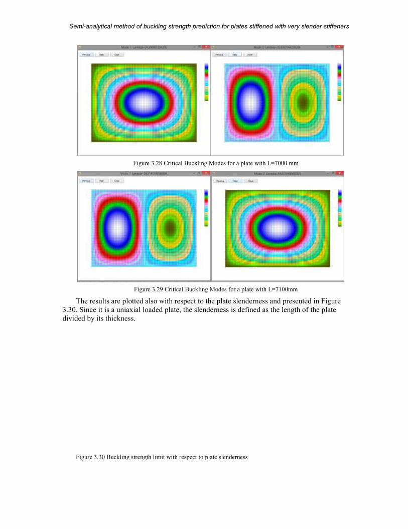
Semi-analytical method of buckling strength prediction
MSc Thesis
Figure 3.28
Figure 3.29
The results are plotted also with respect to the plate slenderness
3.30. Since it is a uniaxial loaded plate,
divided by its thickness.
Figure 3.30 Buckling strength limit with respect to plate slenderness
analytical method of buckling strength prediction for plates stiffened with very slender stiffeners
43 (104)
28 Critical Buckling Modes for a plate with L=7000 mm
29 Critical Buckling Modes for a plate with L=7100mm
with respect to the plate slenderness and presented in
. Since it is a uniaxial loaded plate, the slenderness is defined as the length of the plate
Buckling strength limit with respect to plate slenderness
plates stiffened with very slender stiffeners
A.D. Beju
and presented in Figure
of the plate
Semi-analytical method of buckling strength prediction
MSc Thesis
In order to assess the level of conservativeness of the Eurocode, as well as the one of
Plate, the results are scaled to the buckling strength limit o
presented in Figure 3.31.
Figure 3.31 Buckling strength limit ratio with respect to ANSYS analysis
The maximum out of plane displacements
considered plates range. Both displacements are computed as displacements additional to the
initial imperfection. It can be seen that the displacements obtained using
the trend of the ones obtained from ANSYS analyses. More refined values can be obtained by
increasing the number of degrees of freedom, however with a limited accuracy. The discrepancy
around the length of 4000 mm (about
conservativeness in Figure 3.31, most probably as a consequence of the strength criterion and
increment size. Further investigation of this particular case is needed.
Figure 3.32 Out of plane displacement of a simply supported plate
analytical method of buckling strength prediction for plates stiffened with very slender stiffeners
44 (104)
In order to assess the level of conservativeness of the Eurocode, as well as the one of
, the results are scaled to the buckling strength limit obtained from the ANSYS analysis and
Buckling strength limit ratio with respect to ANSYS analysis
The maximum out of plane displacements at failure are plotted in Figure 3.32
considered plates range. Both displacements are computed as displacements additional to the
initial imperfection. It can be seen that the displacements obtained using Iv-Plate
of the ones obtained from ANSYS analyses. More refined values can be obtained by
increasing the number of degrees of freedom, however with a limited accuracy. The discrepancy
(about 100 slenderness ratio) is in concordance with the level of
, most probably as a consequence of the strength criterion and
increment size. Further investigation of this particular case is needed.
Out of plane displacement of a simply supported plate
plates stiffened with very slender stiffeners
A.D. Beju
In order to assess the level of conservativeness of the Eurocode, as well as the one of Iv-
om the ANSYS analysis and
32 for the
considered plates range. Both displacements are computed as displacements additional to the
Plate are following
of the ones obtained from ANSYS analyses. More refined values can be obtained by
increasing the number of degrees of freedom, however with a limited accuracy. The discrepancy
) is in concordance with the level of
, most probably as a consequence of the strength criterion and
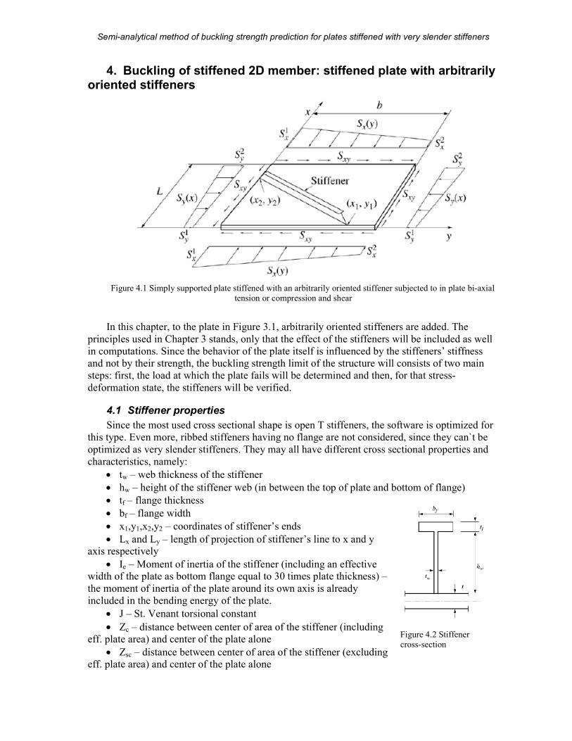
Semi-analytical method of buckling strength prediction for plates stiffened with very slender stiffeners
MSc Thesis 45 (104) A.D. Beju
4. Buckling of stiffened 2D member: stiffened plate with arbitrarily oriented stiffeners
Figure 4.1 Simply supported plate stiffened with an arbitrarily oriented stiffener subjected to in plate bi-axial
tension or compression and shear
In this chapter, to the plate in Figure 3.1, arbitrarily oriented stiffeners are added. The
principles used in Chapter 3 stands, only that the effect of the stiffeners will be included as well
in computations. Since the behavior of the plate itself is influenced by the stiffeners’ stiffness
and not by their strength, the buckling strength limit of the structure will consists of two main
steps: first, the load at which the plate fails will be determined and then, for that stress-
deformation state, the stiffeners will be verified.
4.1 Stiffener properties
Since the most used cross sectional shape is open T stiffeners, the software is optimized for
this type. Even more, ribbed stiffeners having no flange are not considered, since they can`t be
optimized as very slender stiffeners. They may all have different cross sectional properties and
characteristics, namely:
• tw – web thickness of the stiffener
• hw – height of the stiffener web (in between the top of plate and bottom of flange)
• tf – flange thickness
• bf – flange width
• x1,y1,x2,y2 – coordinates of stiffener’s ends
• Lx and Ly – length of projection of stiffener’s line to x and y axis respectively
• Ie – Moment of inertia of the stiffener (including an effective width of the plate as bottom flange equal to 30 times plate thickness) –
the moment of inertia of the plate around its own axis is already
included in the bending energy of the plate.
• J – St. Venant torsional constant
• Zc – distance between center of area of the stiffener (including
eff. plate area) and center of the plate alone
• Zsc – distance between center of area of the stiffener (excluding eff. plate area) and center of the plate alone
Figure 4.2 Stiffener
cross-section
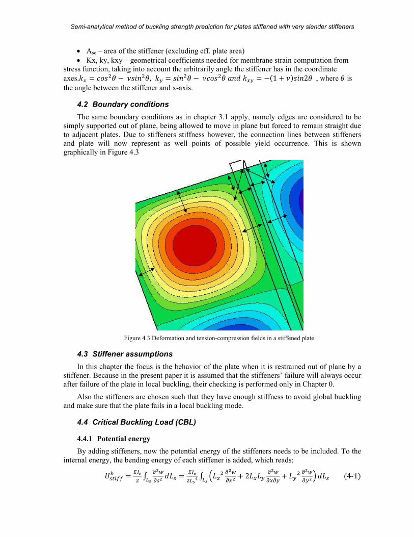
Semi-analytical method of buckling strength prediction for plates stiffened with very slender stiffeners
MSc Thesis 46 (104) A.D. Beju
• Asc – area of the stiffener (excluding eff. plate area)
• Kx, ky, kxy – geometrical coefficients needed for membrane strain computation from stress function, taking into account the arbitrarily angle the stiffener has in the coordinate
axes.+H � ��� â − V��� â, +I � ��� â − V��� â��&+HI � −�1 + V����2â, where â is
the angle between the stiffener and x-axis.
4.2 Boundary conditions
The same boundary conditions as in chapter 3.1 apply, namely edges are considered to be
simply supported out of plane, being allowed to move in plane but forced to remain straight due
to adjacent plates. Due to stiffeners stiffness however, the connection lines between stiffeners
and plate will now represent as well points of possible yield occurrence. This is shown
graphically in Figure 4.3
Figure 4.3 Deformation and tension-compression fields in a stiffened plate
4.3 Stiffener assumptions
In this chapter the focus is the behavior of the plate when it is restrained out of plane by a
stiffener. Because in the present paper it is assumed that the stiffeners’ failure will always occur after failure of the plate in local buckling, their checking is performed only in Chapter 0.
Also the stiffeners are chosen such that they have enough stiffness to avoid global buckling
and make sure that the plate fails in a local buckling mode.
4.4 Critical Buckling Load (CBL)
4.4.1 Potential energy
By adding stiffeners, now the potential energy of the stiffeners needs to be included. To the
internal energy, the bending energy of each stiffener is added, which reads:
�'c�ÍÍ� � ��v � "#$"'# &0'�h � ��v �h¬ � 0H "#$"H# + 20H0I "#$"H"I + 0I "#$"I#�&0'�h �4-1�
Semi-analytical method of buckling strength prediction for plates stiffened with very slender stiffeners
MSc Thesis 47 (104) A.D. Beju
In the above expression, 0' represents the intersecting line between the mid-plane of the
plate and the mid-plate of the stiffener’s web, being defined as0' � o0H + 0I , where 0H � F − F� and 0I � G − G�.
"#$"'# is the partial double derivative of w with respect to the direction along the stiffener and ã� represents the moment of inertia of the cross section consisting of the stiffener and an
effective width of the plate be=30εt, as computed in chapter 4.1.
Depending on their shape, the stiffeners provide also a torsional rigidity to the plate, which
influence its buckling behavior. However, for the slender stiffener with open cross sectional
shape used in this paper, the torsional rigidity they provide is negligible compared to the bending
stiffness from results point of view. Since from computational point of view is quite expensive,
it will be neglected in the current method.
For an open cross section stiffener, the potential energy due to torsion is:
�'c�ÍÍD � 8ä � "#$"'"�&0'�h � ��v �h¬ � 0H0I "#$"I# − "#$"H#� + 0H − 0I � "#$"H"I� &0'�h �4-2�
"#$"'"� represents the partial double derivative of w with respect to the directions normal to
and along the stiffener, while J is St. Venant torsion constant and G represents the strength
modulus (W � � ���U�).
In a complex stiffened plate, stiffeners are usually continuously connected over their whole
length. Therefore, the loading is not distributed only to the plate’s edges but also to the
stiffener’s ends. In the present case, since the stiffeners have rather random orientation, they are
not continuously connected above plate edges and therefore they are not loaded at their ends. If
however, this is the case, it will be specified by the engineer at the beginning of the calculation,
and it will be taken into account while computing the elastic limit state. The potential energy due
to end loads applied on stiffeners is contributing to the geometrical stiffness matrix elements
when solving the eigenvalue problem. The load acting on the stiffener (å'%) is specified by the
engineer or can be calculated proportional to the stiffener’s area. The potential energy is
computed as:
3'c�ÍÍ � 4h^ � "$"'� &0'�h � 4h^ � 0H "$"H + 0I "$"I� &0'�h �4-3�4.5 Buckling strength limit
For estimating the buckling strength limit of the plate, the same assumptions as in Chapter 3
will be used, taking into account the influence of the stiffeners.
Since the results of the load control analysis in Iv-Plate are found to be conservative for the
slender plates which are of interest in the present paper, this method will be left outside of
further comparisons.
Semi-analytical method of buckling strength prediction for plates stiffened with very slender stiffeners
MSc Thesis 48 (104) A.D. Beju
4.5.1 Imperfection amplitudes
The initial deflected shape is taken as the first eigen mode from the elastic analysis, scaled
up to match the specified maximum imperfections, as in chapter 3. Therefore, the initial shape of
the plate reads:
�%�F, G� � ∑ ∑ n�?sin ��H� � sin �?I� �J?������ �4-4�4.5.2 Strength criterion
Brubak[6] proved that the yield of von Misses membrane stresses as a strength criterion can
give un-conservative results, therefore, the strength criterion needs to take into account the
bending stresses in the plate as well. As in Chapter 3, for the plate itself, this reads:
tuvwxy z + ��.Õ uv|,w}~xy � 1 �4-5�
Due to the plate behavior presented in chapter 4.2, the failure of the plate will occur along
the edges or along the stiffener’s lines. In order to reduce the computational costs, the strength
criterion will only be checked along these lines and, once the limit has been found, they will be
computed for the entire plate.
For the stiffened plate in Figure 4.1, the strength and stability of the stiffeners has to be checked as well. Since the current method aims at using the stiffeners to force the plate to fail in
local mode, once the failure load of the plate in local mode has been found, the stiffeners will be
checked for the relevant stresses and deflection shape. If they fail under current situation, a
redesign is needed such that, in the end, their failure load is greater than the plate failure load.
A detailed stiffener’s verification is presented in chapter 5, for a very slender stiffener (class
4), where, during stiffener optimization, precaution is taken such that the stiffener does not fail
before the plate limit load is reached.
4.5.3 Arc-length method
The same principle as in 3.3.5 is applied, with taking into account the effects of the stiffener.
Therefore, the internal potential energy now becomes:
U��(\ + �(� +�'c�ÍÍ� + �)gc �4-6�, where �(\, �(���&�)gc are defined in equations 3-54, 3-55 and 3-56 respectively.
The internal energy of the stiffener is found by integrating the square of its elongation over
the whole stiffener (double integral over the area and over its length). From the same reasons as
in chapter 4.3, the internal energy due to torsional restrain of the stiffener is neglected.
Therefore, the internal energy due to bending of the stiffener reads:
�'c�ÍÍ� � � � � R' &æ'&0'çh�h �4-7�In chapter 4.3, where the initial shape of the structure is considered perfect, the stiffener has
the same elongation as the plate membrane elongation. Because of the initial deformation shape,
as well as the additional deformation due to bending, the elongation if the stiffener is now either
decreased or increased depending on the curvature of the plate.
Semi-analytical method of buckling strength prediction for plates stiffened with very slender stiffeners
MSc Thesis 49 (104) A.D. Beju
Because the stiffener is added only on one side of the plate, there will be a shift of neutral
axis in the cross section, from the mid-plane of the plate (z=0) to the center of area of the
effective stiffener (z=zc). Therefore, the elongation through the height of the stiffeners’ cross-
section can be written as a function of the elongation in the membrane and the additional
elongation due to curvature of the plate along the stiffener, as: R'�Y� � R'\ − �Y − Y�� "#$"'# �4-8�R'\ is the membrane strains of the plate, which equals the elongation in the center of area of
the effective cross-section consisting of the stiffener and an effective width of the plate of 30*t; z
is the out of plane coordinate (along the height of the stiffener’ cross-section) measured from the
mid-plane of the plate and zc is the shift of neutral axis.
The membrane strains R'\ along the stiffener are found by coordinate transformation of the stresses from Hooke’s law to the directions perpendicular and along the stiffener. For this, the
geometrical parameters kx, ky and kxy defined in chapter 4.1 are used. By further replacing the
stresses by Airy’s stress functions as in equation 3-33 the membrane strains for each stress
condition are defined as:
R'\ � �� +H "#x"H# + +I "#x"I# + +HI "#x"H"I� �4-9�As defined by Airy’s stress function, the above equation will consist of a linear part due to
external stresses and a non-linear one, due to redistribution of stresses. Because the stiffeners are
designed a lot stiffer than the plate, the redistribution of stresses in the plate membrane has
negligible effect on the stiffeners. Therefore, the non-linear terms in the above equation can be
omitted, as the computational effort is not worth the gain it brings.
As found in chapter 3 as well, the computation of membrane strains due to stress redistribution in the plate is the most time consuming operation. Due to stiffener’s height, the
bending strains along the stiffener are significantly bigger than the membrane strains. Therefore,
when plotting equation 4-8 in equation 4-7, the squared terms of membrane strain can be
neglected.
Taking these assumptions into consideration, by evaluating equation 4-7, the internal energy
due to bending of the stiffener becomes: �'c�ÍÍ� � ��v � "#$"'# � &0'�h − ���æ' � "#$"'# R'\&0'�h �4-10�4.6 Eurocode procedure – reduced stress method
For stiffened plates, the reduced stress method, together with annex B represents an
alternative of determining plate’s buckling strength. However this is not taking into account the
very slender nature of the stiffeners, therefore considering that the stiffeners have sufficient
stability in order for the plate to fail first.
For non-uniform members, such as arbitrarily stiffened plates, ��)value should be obtained
from finite element analysis. As shown in the results of current paper, current method provides
accurate values for the first eigenvalues of the elastic buckling analysis. Therefore, these values
will be used instead of FEM values.
The procedure for computing the buckling stress of such plate as in Figure 4.1 is following
the procedure presented in chapter 10 of EC1993-1-5 [1].
The unity check for a certain combination of biaxial compression or tension loads and shear
load is defined by: �� � xèéxêé � xèéëìíl¸,kîèéïÄÃ� �ÄÃë{íl¸,k ≤ 1 �4-11�
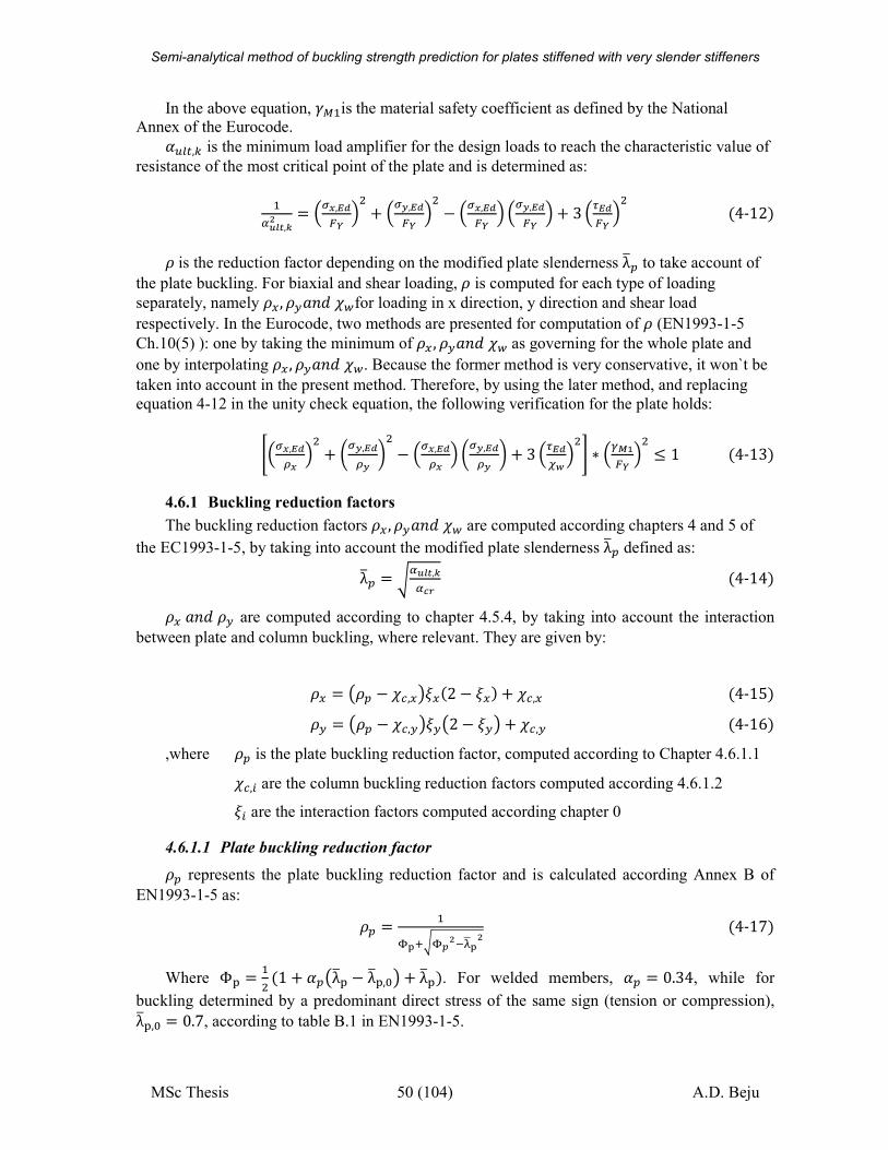
Semi-analytical method of buckling strength prediction for plates stiffened with very slender stiffeners
MSc Thesis 50 (104) A.D. Beju
In the above equation, S��is the material safety coefficient as defined by the National Annex of the Eurocode. ��jc,i is the minimum load amplifier for the design loads to reach the characteristic value of
resistance of the most critical point of the plate and is determined as:
�{íl¸,k# � u~,èéx´ � + uy,èéx´ � − u~,èéx´ � uy,èéx´ � + 3 ðèéx´ � �4-12�Ðis the reduction factor depending on the modified plate slenderness λ®( to take account of
the plate buckling. For biaxial and shear loading,Ð is computed for each type of loading
separately, namely ÐH, ÐI��&Ù$for loading in x direction, y direction and shear load
respectively. In the Eurocode, two methods are presented for computation of Ð (EN1993-1-5
Ch.10(5) ): one by taking the minimum of ÐH , ÐI��&Ù$as governing for the whole plate and
one by interpolating ÐH , ÐI��&Ù$. Because the former method is very conservative, it won`t be
taken into account in the present method. Therefore, by using the later method, and replacing
equation 4-12 in the unity check equation, the following verification for the plate holds:
ñ u~,èéë~ � + tuy,èéëy z − u~,èéë~ � tuy,èéëy z + 3 ðèéòó� ô ∗ �ÄÃx´ � ≤ 1 �4-13�4.6.1 Buckling reduction factors
The buckling reduction factors ÐH , ÐI��&Ù$ are computed according chapters 4 and 5 of
the EC1993-1-5, by taking into account the modified plate slenderness λ®( defined as:
λ®( � o{íl¸,k{Ò �4-14�ÐH��&ÐI are computed according to chapter 4.5.4, by taking into account the interaction
between plate and column buckling, where relevant. They are given by:
ÐH � pÐ( − Ù�,HqÛH�2 − ÛH� + Ù�,H �4-15�ÐI � pÐ( − Ù�,IqÛIp2 − ÛIq + Ù�,I �4-16�
,where Ð( is the plate buckling reduction factor, computed according to Chapter 4.6.1.1
Ù�,� are the column buckling reduction factors computed according 4.6.1.2
Û� are the interaction factors computed according chapter 0
4.6.1.1 Plate buckling reduction factor Ð( represents the plate buckling reduction factor and is calculated according Annex B of
EN1993-1-5 as:
Ð( � �Ú¦�oÚ�#Tª«¦# �4-17�
Where Φõ � � �1 + �(pλ®õ − λ®õ,%q + λ®õ�. For welded members, �( � 0.34, while for
buckling determined by a predominant direct stress of the same sign (tension or compression), λ®õ,% � 0.7, according to table B.1 in EN1993-1-5.
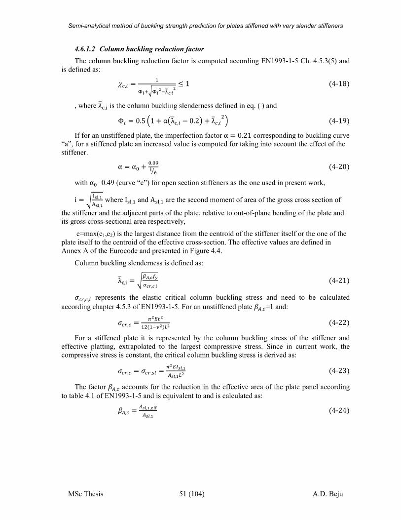
Semi-analytical method of buckling strength prediction for plates stiffened with very slender stiffeners
MSc Thesis 51 (104) A.D. Beju
4.6.1.2 Column buckling reduction factor
The column buckling reduction factor is computed according EN1993-1-5 Ch. 4.5.3(5) and
is defined as:
Ù�,� � �Ú.�oÚ.#Tª«Ò,.# ≤ 1 �4-18�
, where λ®ö,à is the column buckling slenderness defined in eq. ( ) and
Φ� � 0.5 1 + αpλ®�,� − 0.2q + λ®�,� � �4-19�If for an unstiffened plate, the imperfection factor α � 0.21 corresponding to buckling curve
“a”, for a stiffened plate an increased value is computed for taking into account the effect of the stiffener.
α � α% + %.%÷à øù �4-20�with α%=0.49 (curve “c”) for open section stiffeners as the one used in present work,
i � o ú¥û,Ãü¥û,à where Iþ�,� and Aþ�,� are the second moment of area of the gross cross section of
the stiffener and the adjacent parts of the plate, relative to out-of-plane bending of the plate and
its gross cross-sectional area respectively,
e=max(e1,e2) is the largest distance from the centroid of the stiffener itself or the one of the
plate itself to the centroid of the effective cross-section. The effective values are defined in
Annex A of the Eurocode and presented in Figure 4.4.
Column buckling slenderness is defined as:
λ®ö,à � o��,ÒÍyuÒ ,Ò,. �4-21�N�),�,� represents the elastic critical column buckling stress and need to be calculated
according chapter 4.5.3 of EN1993-1-5. For an unstiffened plate �ç,�=1 and:
N�),� � �#�c#� ��TU#��# �4-22�For a stiffened plate it is represented by the column buckling stress of the stiffener and
effective platting, extrapolated to the largest compressive stress. Since in current work, the
compressive stress is constant, the critical column buckling stress is derived as:
N�),� � N�),'j � �#��hl,Ãçhl,Ã�# �4-23�The factor �ç,� accounts for the reduction in the effective area of the plate panel according
to table 4.1 of EN1993-1-5 and is equivalent to and is calculated as:
�ç,� � çhl,Ã,§��çhl,à �4-24�
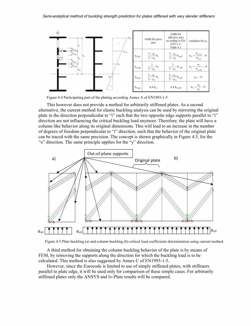
Semi-analytical method of buckling strength prediction for plates stiffened with very slender stiffeners
MSc Thesis 52 (104) A.D. Beju
Figure 4.4 Participating part of the plating according Annex A of EN1993-1-5
This however does not provide a method for arbitrarily stiffened plates. As a second
alternative, the current method for elastic buckling analysis can be used by mirroring the original plate in the direction perpendicular to “i” such that the two opposite edge supports parallel to “i”
direction are not influencing the critical buckling load anymore. Therefore, the plate will have a
column like behavior along its original dimensions. This will lead to an increase in the number
of degrees of freedom perpendicular to “i” direction, such that the behavior of the original plate
can be traced with the same precision. The concept is shown graphically in Figure 4.5, for the
“x” direction. The same principle applies for the “y” direction.
A third method for obtaining the column buckling behavior of the plate is by means of
FEM, by removing the supports along the direction for which the buckling load is to be
calculated. This method is also suggested by Annex C of EN1993-1-5.
However, since the Eurocode is limited to use of simply stiffened plates, with stiffeners
parallel to plate edge, it will be used only for comparison of these simple cases. For arbitrarily
stiffened plates only the ANSYS and Iv-Plate results will be compared.
Out-of-plane supports
σx0 σx0 σx0
a) b) Original plate
Figure 4.5 Plate buckling (a) and column buckling (b) critical load coefficients determination using current method.
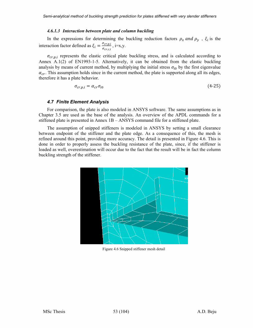
Semi-analytical method of buckling strength prediction for plates stiffened with very slender stiffeners
MSc Thesis 53 (104) A.D. Beju
4.6.1.3 Interaction between plate and column buckling
In the expressions for determining the buckling reduction factors ÐH ��&ÐI , Û� is the
interaction factor defined as Û� � uÒ ,�,.uÒ ,Ò,. , i=x,y.
N�),(,� represents the elastic critical plate buckling stress, and is calculated according to
Annex A.1(2) of EN1993-1-5. Alternatively, it can be obtained from the elastic buckling
analysis by means of current method, by multiplying the initial stress N�% by the first eigenvalue ��) . This assumption holds since in the current method, the plate is supported along all its edges, therefore it has a plate behavior. N�),(,� � ��)N�% �4-25�
4.7 Finite Element Analysis
For comparison, the plate is also modeled in ANSYS software. The same assumptions as in
Chapter 3.5 are used as the base of the analysis. An overview of the APDL commands for a
stiffened plate is presented in Annex 1B – ANSYS command file for a stiffened plate.
The assumption of snipped stiffeners is modeled in ANSYS by setting a small clearance
between endpoint of the stiffener and the plate edge. As a consequence of this, the mesh is
refined around this point, providing more accuracy. The detail is presented in Figure 4.6. This is
done in order to properly assess the buckling resistance of the plate, since, if the stiffener is
loaded as well, overestimation will occur due to the fact that the result will be in fact the column
buckling strength of the stiffener.
Figure 4.6 Snipped stiffener mesh detail
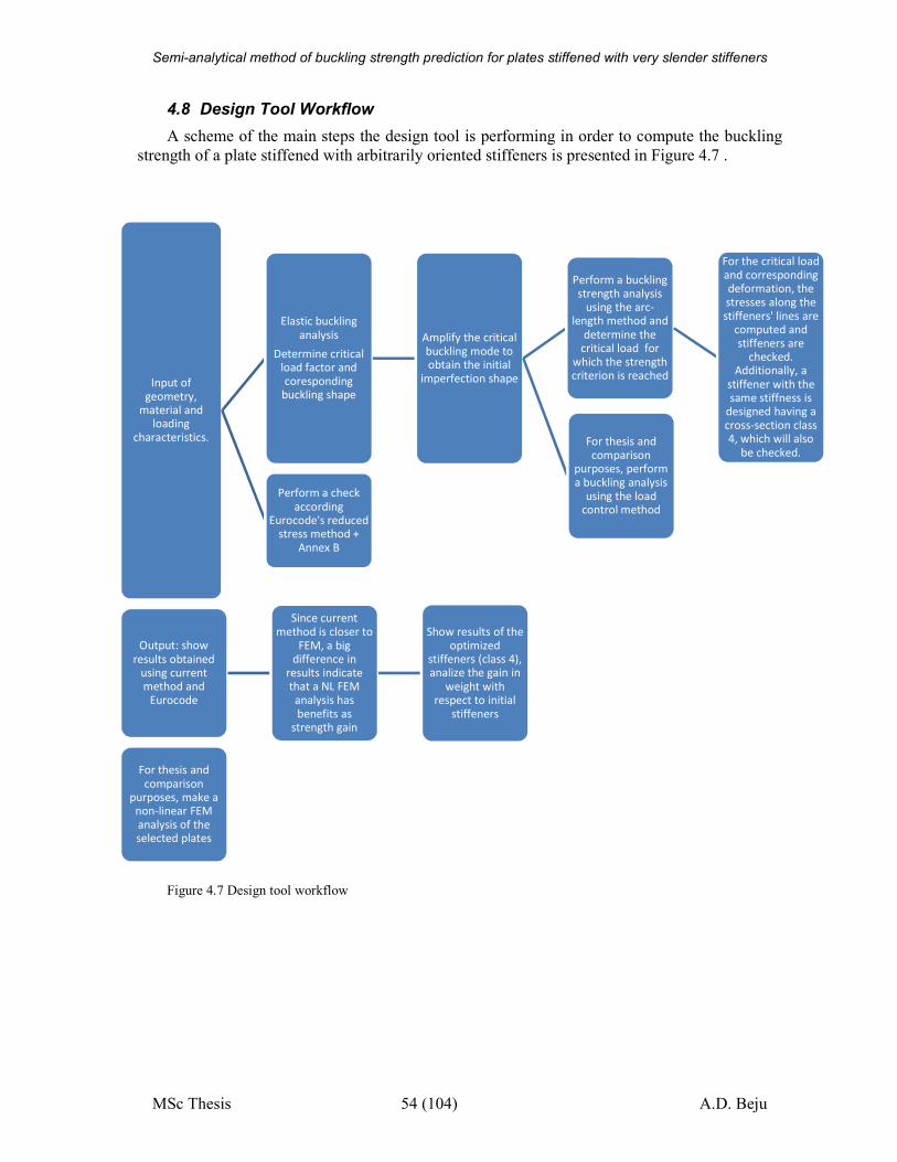
Semi-analytical method of buckling strength prediction for plates stiffened with very slender stiffeners
MSc Thesis 54 (104) A.D. Beju
4.8 Design Tool Workflow
A scheme of the main steps the design tool is performing in order to compute the buckling
strength of a plate stiffened with arbitrarily oriented stiffeners is presented in Figure 4.7 .
Figure 4.7 Design tool workflow
Input of
geometry,
material and
loading
characteristics.
Elastic buckling
analysis
Determine critical
load factor and
coresponding
buckling shape
Amplify the critical
buckling mode to
obtain the initial
imperfection shape
Perform a buckling
strength analysis
using the arc-
length method and
determine the
critical load for
which the strength
criterion is reached
For the critical load
and corresponding
deformation, the
stresses along the
stiffeners' lines are
computed and
stiffeners are
checked.
Additionally, a
stiffener with the
same stiffness is
designed having a
cross-section class
4, which will also
be checked.For thesis and
comparison
purposes, perform
a buckling analysis
using the load
control method
Perform a check
according
Eurocode's reduced
stress method +
Annex B
Output: show
results obtained
using current
method and
Eurocode
Since current
method is closer to
FEM, a big
difference in
results indicate
that a NL FEM
analysis has
benefits as
strength gain
Show results of the
optimized
stiffeners (class 4),
analize the gain in
weight with
respect to initial
stiffeners
For thesis and
comparison
purposes, make a
non-linear FEM
analysis of the
selected plates
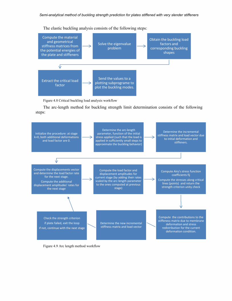
Semi-analytical method of buckling strength prediction for plates stiffened with very slender stiffeners
MSc Thesis 55 (104) A.D. Beju
The elastic buckling analysis consists of the following steps:
Figure 4.8 Critical buckling load analysis workflow
The arc-length method for buckling strength limit determination consists of the following
steps:
Figure 4.9 Arc length method workflow
Compute the material
and geometrical
stiffness matrices from the potential energies of
the plate and stiffeners
Solve the eigenvalue
problem
Obtain the buckling load
factors and
corresponding buckling shapes
Extract the critical load
factor
Send the values to a
plotting subprograme to
plot the buckling modes.
Initialize the procedure: at stage
k=0, both additional deformations
and load factor are 0.
Determine the arc-length
parameter, function of the initial
stress applied (such that the load is
applied in sufficiently small steps to
approximate the buckling behavior)
Determine the incremental
stiffness matrix and load vector due
to initial deformation and
stiffeners.
Compute the displacements vector
and determine the load factor rate
for the next stage.
Compute the additional
displacement amplitudes' rates for
the next stage
Compute the load factor and
displacement amplitudes for
current stage (by adding their rates
scaled by the arc-length parameter
to the ones computed at previous
stage)
Compute Airy's stress function
coefficients fij
Compute the stresses along critical
lines (points) and return the
strength criterion unity check
Compute the contributions to the
stiffeness matrix due to membrane
deformation and stress
redistribution for the current
deformation condition.
Determine the new incremental
stiffness matrix and load vector
Check the strength criterion
if plate failed, exit the loop
if not, continue with the next stage
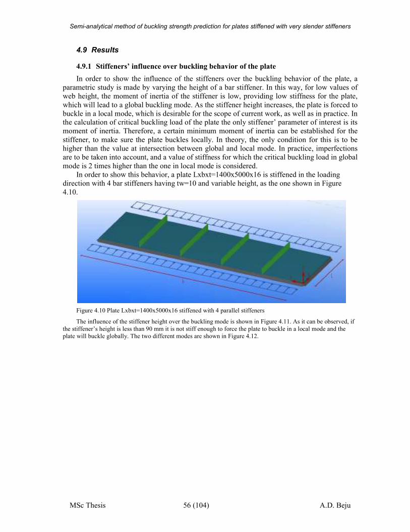
Semi-analytical method of buckling strength prediction for plates stiffened with very slender stiffeners
MSc Thesis 56 (104) A.D. Beju
4.9 Results
4.9.1 Stiffeners’ influence over buckling behavior of the plate
In order to show the influence of the stiffeners over the buckling behavior of the plate, a
parametric study is made by varying the height of a bar stiffener. In this way, for low values of
web height, the moment of inertia of the stiffener is low, providing low stiffness for the plate,
which will lead to a global buckling mode. As the stiffener height increases, the plate is forced to
buckle in a local mode, which is desirable for the scope of current work, as well as in practice. In the calculation of critical buckling load of the plate the only stiffener’ parameter of interest is its
moment of inertia. Therefore, a certain minimum moment of inertia can be established for the
stiffener, to make sure the plate buckles locally. In theory, the only condition for this is to be
higher than the value at intersection between global and local mode. In practice, imperfections
are to be taken into account, and a value of stiffness for which the critical buckling load in global
mode is 2 times higher than the one in local mode is considered.
In order to show this behavior, a plate Lxbxt=1400x5000x16 is stiffened in the loading
direction with 4 bar stiffeners having tw=10 and variable height, as the one shown in Figure
4.10.
Figure 4.10 Plate Lxbxt=1400x5000x16 stiffened with 4 parallel stiffeners
The influence of the stiffener height over the buckling mode is shown in Figure 4.11. As it can be observed, if
the stiffener’s height is less than 90 mm it is not stiff enough to force the plate to buckle in a local mode and the
plate will buckle globally. The two different modes are shown in Figure 4.12.
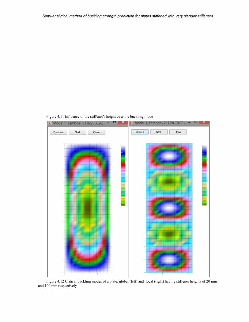
Semi-analytical method of buckling strength prediction
MSc Thesis
Figure 4.11 Influence of the stiffener's height over the buckling mode
Figure 4.12 Critical buckling mode
and 100 mm respectively
analytical method of buckling strength prediction for plates stiffened with very slender stiffeners
57 (104)
Influence of the stiffener's height over the buckling mode
Critical buckling modes of a plate: global (left) and local (right) having stiffener heights of 20 mm
plates stiffened with very slender stiffeners
A.D. Beju
having stiffener heights of 20 mm
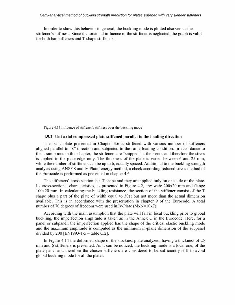
Semi-analytical method of buckling strength prediction
MSc Thesis
In order to show this behavior in general, the buckling mode is plotted also versus the
stiffener’s stiffness. Since the torsional influence of the stiffener is neglected, the graph
for both bar stiffeners and T-shape stiffeners.
Figure 4.13 Influence of stiffener's stiffness
4.9.2 Uni-axial compressed plate stiffened parallel to the loading direction
The basic plate presented in Chapter
aligned parallel to “x” direction and subjected to the same loading condition. In accordance to
the assumptions in this chapter, the stiffeners are “snipp
is applied to the plate edge only.
while the number of stiffeners can be up to 6, equally spaced. A
analysis using ANSYS and Iv-Plate
the Eurocode is performed as presented in chapter
The stiffeners’ cross-section is a T shape and they are applied only on one side of the plate.
Its cross-sectional characteristics, as presented in
100x20 mm. In calculating the buckling resistance, the section of the stiffener consist of the T
shape plus a part of the plate of width eq
available. This is in accordance with the prescription in chapter 9 of the Eurocode.number of 70 degrees of freedom were used in
According with the main assumption that the pl
buckling, the imperfection amplitude is taken as in the Annex C in the Eurocode. Here, for a
panel or subpanel, the imperfection applied has the shape of the critical elastic buckling mode
and the maximum amplitude is computed as the minimum in
divided by 200 [EN1993-1-5 – table C.2].
In Figure 4.14 the deformed shape of the
mm and 6 stiffeners is presented. As it can be noticed, the buckling mode is a local one, of the
plate panel and therefore the chosen stiffeners are considered to be sufficiently stiff to avoid
global buckling mode for all the plates
analytical method of buckling strength prediction for plates stiffened with very slender stiffeners
58 (104)
In order to show this behavior in general, the buckling mode is plotted also versus the
stiffener’s stiffness. Since the torsional influence of the stiffener is neglected, the graph
shape stiffeners.
Influence of stiffener's stiffness over the buckling mode
axial compressed plate stiffened parallel to the loading direction
presented in Chapter 3.6 is stiffened with various number
aligned parallel to “x” direction and subjected to the same loading condition. In accordance to
the assumptions in this chapter, the stiffeners are “snipped” at their ends and therefore the stress
is applied to the plate edge only. The thickness of the plate is varied between 6 and 25 mm,
while the number of stiffeners can be up to 6, equally spaced. Additional to the buckling strength
Plate’ energy method, a check according reduced stress method of
the Eurocode is performed as presented in chapter 4.6.
section is a T shape and they are applied only on one side of the plate.
sectional characteristics, as presented in Figure 4.2, are: web: 200x20 mm and flange
In calculating the buckling resistance, the section of the stiffener consist of the T
shape plus a part of the plate of width equal to 30εt but not more than the actual dimension
. This is in accordance with the prescription in chapter 9 of the Eurocode.number of 70 degrees of freedom were used in Iv-Plate (MxN=10x7).
According with the main assumption that the plate will fail in local buckling prior to global
buckling, the imperfection amplitude is taken as in the Annex C in the Eurocode. Here, for a
panel or subpanel, the imperfection applied has the shape of the critical elastic buckling mode
litude is computed as the minimum in-plane dimension of the subpanel
table C.2].
the deformed shape of the stockiest plate analyzed, having a thickness of 25
nted. As it can be noticed, the buckling mode is a local one, of the
plate panel and therefore the chosen stiffeners are considered to be sufficiently stiff to avoid
for all the plates.
plates stiffened with very slender stiffeners
A.D. Beju
In order to show this behavior in general, the buckling mode is plotted also versus the
stiffener’s stiffness. Since the torsional influence of the stiffener is neglected, the graph is valid
axial compressed plate stiffened parallel to the loading direction
number of stiffeners
aligned parallel to “x” direction and subjected to the same loading condition. In accordance to
ed” at their ends and therefore the stress
The thickness of the plate is varied between 6 and 25 mm,
dditional to the buckling strength
check according reduced stress method of
section is a T shape and they are applied only on one side of the plate.
, are: web: 200x20 mm and flange
In calculating the buckling resistance, the section of the stiffener consist of the T
but not more than the actual dimension
. This is in accordance with the prescription in chapter 9 of the Eurocode. A total
ate will fail in local buckling prior to global
buckling, the imperfection amplitude is taken as in the Annex C in the Eurocode. Here, for a
panel or subpanel, the imperfection applied has the shape of the critical elastic buckling mode
plane dimension of the subpanel
plate analyzed, having a thickness of 25
nted. As it can be noticed, the buckling mode is a local one, of the
plate panel and therefore the chosen stiffeners are considered to be sufficiently stiff to avoid
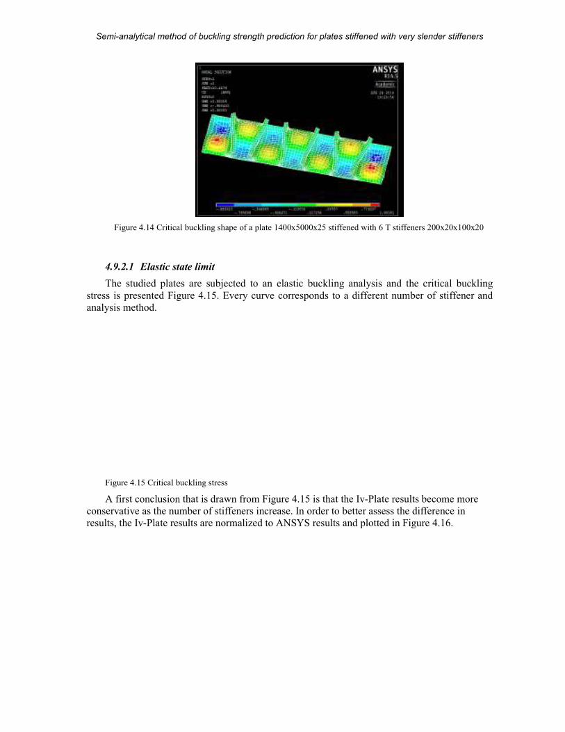
Semi-analytical method of buckling strength prediction
MSc Thesis
Figure 4.14 Critical buckling shape of a plate 1400x5000x25 stiffened with 6 T stiffeners 200x20x100x20
4.9.2.1 Elastic state limit
The studied plates are subjected to an elastic buckling analysis and the critical buckling
stress is presented Figure 4.15. Every curve corresponds to a different number of stiffener and
analysis method.
Figure 4.15 Critical buckling stress
A first conclusion that is drawn from
conservative as the number of stiffeners increase. In order to better assess the difference in
results, the Iv-Plate results are normalized to ANSYS results and plotted in
analytical method of buckling strength prediction for plates stiffened with very slender stiffeners
59 (104)
Critical buckling shape of a plate 1400x5000x25 stiffened with 6 T stiffeners 200x20x100x20
The studied plates are subjected to an elastic buckling analysis and the critical buckling
. Every curve corresponds to a different number of stiffener and
Critical buckling stress
A first conclusion that is drawn from Figure 4.15 is that the Iv-Plate results become more
conservative as the number of stiffeners increase. In order to better assess the difference in
results are normalized to ANSYS results and plotted in Figure
plates stiffened with very slender stiffeners
A.D. Beju
Critical buckling shape of a plate 1400x5000x25 stiffened with 6 T stiffeners 200x20x100x20
The studied plates are subjected to an elastic buckling analysis and the critical buckling
. Every curve corresponds to a different number of stiffener and
results become more
conservative as the number of stiffeners increase. In order to better assess the difference in
Figure 4.16.
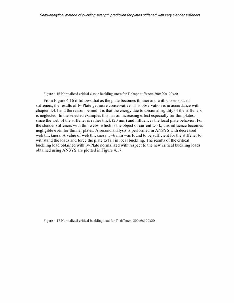
Semi-analytical method of buckling strength prediction
MSc Thesis
Figure 4.16 Normalized critical elastic buckling stress
From Figure 4.16 it follows that as the plate becomes thinner and with closer spaced
stiffeners, the results of Iv-Plate
chapter 4.4.1 and the reason behind it is that the energy due to torsional rigidity of the stiffeners
is neglected. In the selected examples this has an increasing effect especially for thin plates,
since the web of the stiffener is rather thick (20 mm) and influences the local plate behavior. For
the slender stiffeners with thin webs, which
negligible even for thinner plates.
web thickness. A value of web thickness t
withstand the loads and force the plate to fail in loca
buckling load obtained with Iv-Plate
obtained using ANSYS are plotted in
Figure 4.17 Normalized critical buckling load for T stiffeners 200x6x100x20
analytical method of buckling strength prediction for plates stiffened with very slender stiffeners
60 (104)
Normalized critical elastic buckling stress for T-shape stiffeners 200x20x100x20
it follows that as the plate becomes thinner and with closer spaced
get more conservative. This observation is in accordance with
and the reason behind it is that the energy due to torsional rigidity of the stiffeners
ted examples this has an increasing effect especially for thin plates,
since the web of the stiffener is rather thick (20 mm) and influences the local plate behavior. For
the slender stiffeners with thin webs, which is the object of current work, this infl
negligible even for thinner plates. A second analysis is performed in ANSYS with decreased
A value of web thickness tw=6 mm was found to be sufficient for the stiffener to
withstand the loads and force the plate to fail in local buckling. The results of the critical
Plate normalized with respect to the new critical buckling loads
obtained using ANSYS are plotted in Figure 4.17.
Normalized critical buckling load for T stiffeners 200x6x100x20
plates stiffened with very slender stiffeners
A.D. Beju
shape stiffeners 200x20x100x20
it follows that as the plate becomes thinner and with closer spaced
get more conservative. This observation is in accordance with
and the reason behind it is that the energy due to torsional rigidity of the stiffeners
ted examples this has an increasing effect especially for thin plates,
since the web of the stiffener is rather thick (20 mm) and influences the local plate behavior. For
the object of current work, this influence becomes
A second analysis is performed in ANSYS with decreased
=6 mm was found to be sufficient for the stiffener to
l buckling. The results of the critical
normalized with respect to the new critical buckling loads
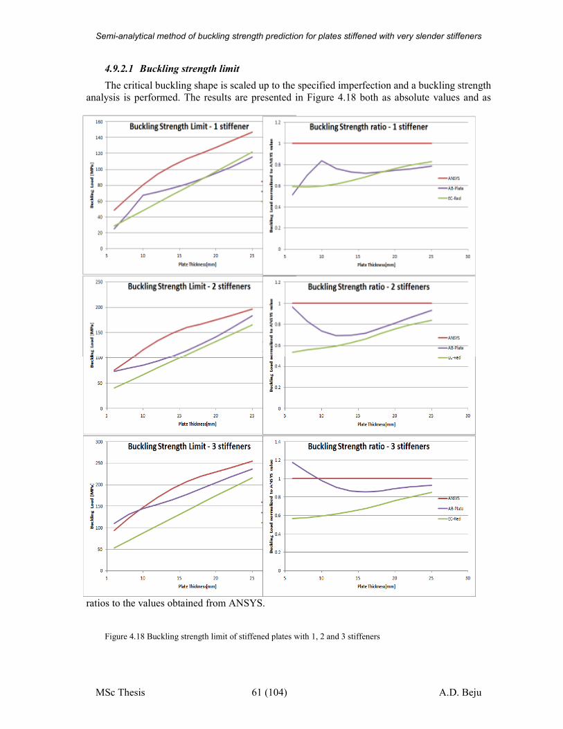
Semi-analytical method of buckling strength prediction for plates stiffened with very slender stiffeners
MSc Thesis 61 (104) A.D. Beju
4.9.2.1 Buckling strength limit
The critical buckling shape is scaled up to the specified imperfection and a buckling strength
analysis is performed. The results are presented in Figure 4.18 both as absolute values and as
ratios to the values obtained from ANSYS.
Figure 4.18 Buckling strength limit of stiffened plates with 1, 2 and 3 stiffeners
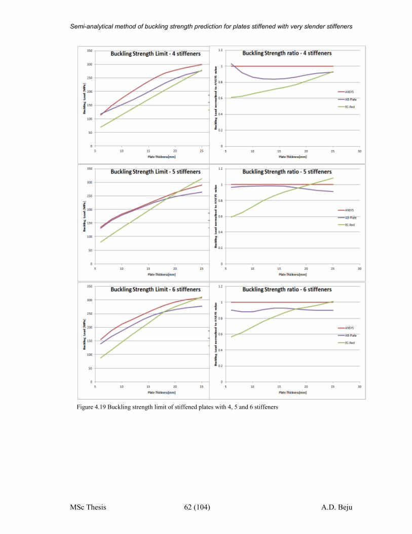
Semi-analytical method of buckling strength prediction for plates stiffened with very slender stiffeners
MSc Thesis 62 (104) A.D. Beju
Figure 4.19 Buckling strength limit of stiffened plates with 4, 5 and 6 stiffeners
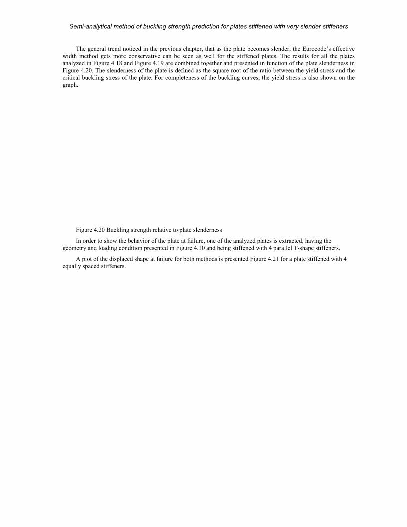
Semi-analytical method of buckling strength prediction
MSc Thesis
The general trend noticed in the previous chapter, that as the plate becomes slender, the Eurocode’s effective
width method gets more conservative can be seen as well for the stiffened plates. The results for all the plates
analyzed in Figure 4.18 and Figure 4.19
Figure 4.20. The slenderness of the plate is defined as the square root of the ratio between the yield stress and the
critical buckling stress of the plate. For completeness of the buckling curves, the yield stress is also show
graph.
Figure 4.20 Buckling strength relative to plate slenderness
In order to show the behavior of the plate at failure, one of the analyzed plates is extracted
geometry and loading condition presented in
A plot of the displaced shape at failure
equally spaced stiffeners.
analytical method of buckling strength prediction for plates stiffened with very slender stiffeners
63 (104)
The general trend noticed in the previous chapter, that as the plate becomes slender, the Eurocode’s effective
conservative can be seen as well for the stiffened plates. The results for all the plates
19 are combined together and presented in function of the plate slenderness
. The slenderness of the plate is defined as the square root of the ratio between the yield stress and the
critical buckling stress of the plate. For completeness of the buckling curves, the yield stress is also show
Buckling strength relative to plate slenderness
In order to show the behavior of the plate at failure, one of the analyzed plates is extracted,
condition presented in Figure 4.10 and being stiffened with 4 parallel T-shape
displaced shape at failure for both methods is presented Figure 4.21 for a plate stiffened with 4
plates stiffened with very slender stiffeners
A.D. Beju
The general trend noticed in the previous chapter, that as the plate becomes slender, the Eurocode’s effective
conservative can be seen as well for the stiffened plates. The results for all the plates
are combined together and presented in function of the plate slenderness in
. The slenderness of the plate is defined as the square root of the ratio between the yield stress and the
critical buckling stress of the plate. For completeness of the buckling curves, the yield stress is also shown on the
, having the
shape stiffeners.
for a plate stiffened with 4
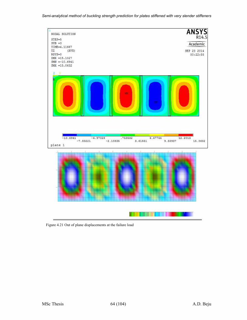
Semi-analytical method of buckling strength prediction for plates stiffened with very slender stiffeners
MSc Thesis 64 (104) A.D. Beju
Figure 4.21 Out of plane displacements at the failure load
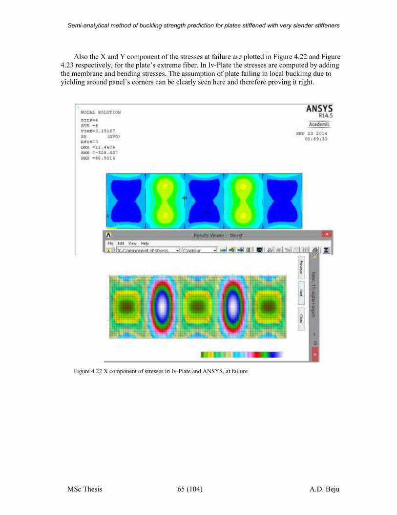
Semi-analytical method of buckling strength prediction for plates stiffened with very slender stiffeners
MSc Thesis 65 (104) A.D. Beju
Also the X and Y component of the stresses at failure are plotted in Figure 4.22 and Figure
4.23 respectively, for the plate’s extreme fiber. In Iv-Plate the stresses are computed by adding
the membrane and bending stresses. The assumption of plate failing in local buckling due to
yielding around panel’s corners can be clearly seen here and therefore proving it right.
Figure 4.22 X component of stresses in Iv-Plate and ANSYS, at failure
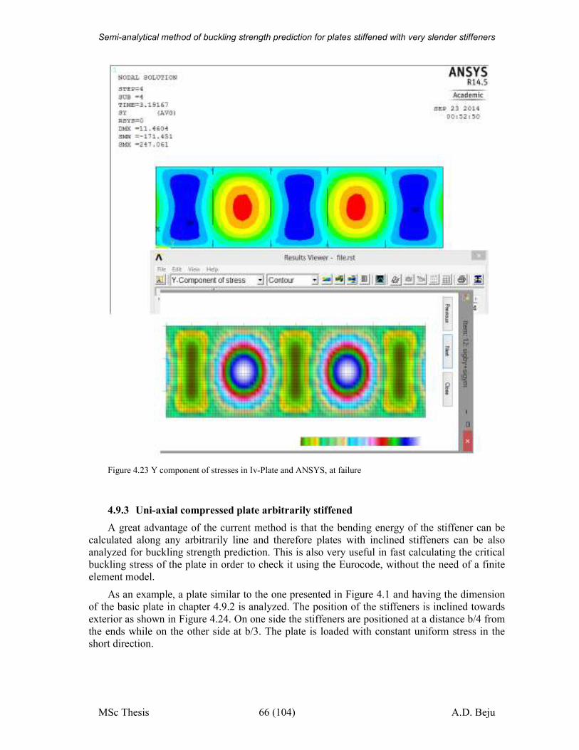
Semi-analytical method of buckling strength prediction for plates stiffened with very slender stiffeners
MSc Thesis 66 (104) A.D. Beju
Figure 4.23 Y component of stresses in Iv-Plate and ANSYS, at failure
4.9.3 Uni-axial compressed plate arbitrarily stiffened
A great advantage of the current method is that the bending energy of the stiffener can be
calculated along any arbitrarily line and therefore plates with inclined stiffeners can be also
analyzed for buckling strength prediction. This is also very useful in fast calculating the critical
buckling stress of the plate in order to check it using the Eurocode, without the need of a finite
element model.
As an example, a plate similar to the one presented in Figure 4.1 and having the dimension
of the basic plate in chapter 4.9.2 is analyzed. The position of the stiffeners is inclined towards
exterior as shown in Figure 4.24. On one side the stiffeners are positioned at a distance b/4 from
the ends while on the other side at b/3. The plate is loaded with constant uniform stress in the
short direction.
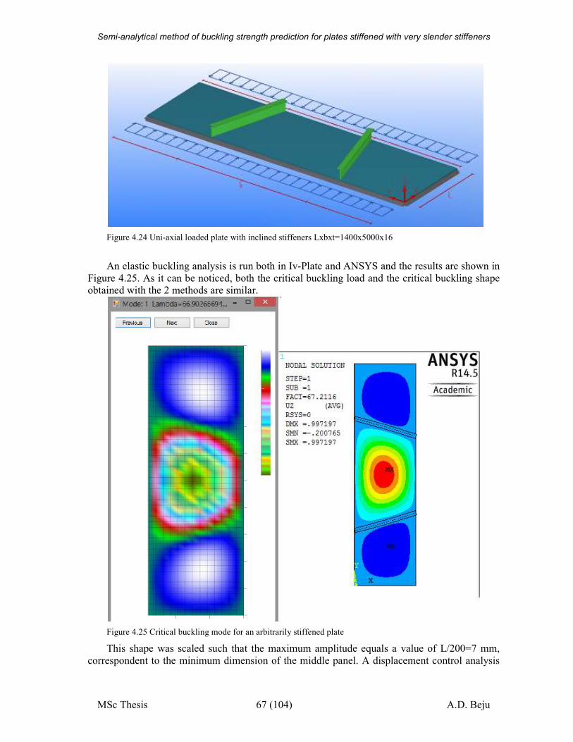
Semi-analytical method of buckling strength prediction for plates stiffened with very slender stiffeners
MSc Thesis 67 (104) A.D. Beju
Figure 4.24 Uni-axial loaded plate with inclined stiffeners Lxbxt=1400x5000x16
An elastic buckling analysis is run both in Iv-Plate and ANSYS and the results are shown in
Figure 4.25. As it can be noticed, both the critical buckling load and the critical buckling shape obtained with the 2 methods are similar.
Figure 4.25 Critical buckling mode for an arbitrarily stiffened plate
This shape was scaled such that the maximum amplitude equals a value of L/200=7 mm,
correspondent to the minimum dimension of the middle panel. A displacement control analysis
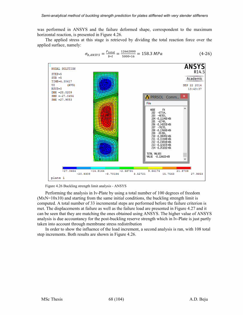
Semi-analytical method of buckling strength prediction for plates stiffened with very slender stiffeners
MSc Thesis 68 (104) A.D. Beju
was performed in ANSYS and the failure deformed shape, correspondent to the maximum
horizontal reaction, is presented in Figure 4.26.
The applied stress at this stage is retrieved by dividing the total reaction force over the
applied surface, namely:
N�,çJ�³� � x¸�¸}l�∗c � � %%%Õ%%%∗� � 158.3å� �4-26�
Figure 4.26 Buckling strength limit analysis - ANSYS
Performing the analysis in Iv-Plate by using a total number of 100 degrees of freedom
(MxN=10x10) and starting from the same initial conditions, the buckling strength limit is
computed. A total number of 33 incremental steps are performed before the failure criterion is
met. The displacements at failure as well as the failure load are presented in Figure 4.27 and it
can be seen that they are matching the ones obtained using ANSYS. The higher value of ANSYS
analysis is due accountancy for the post-buckling reserve strength which in Iv-Plate is just partly
taken into account through membrane stress redistribution
In order to show the influence of the load increment, a second analysis is ran, with 108 total
step increments. Both results are shown in Figure 4.26.
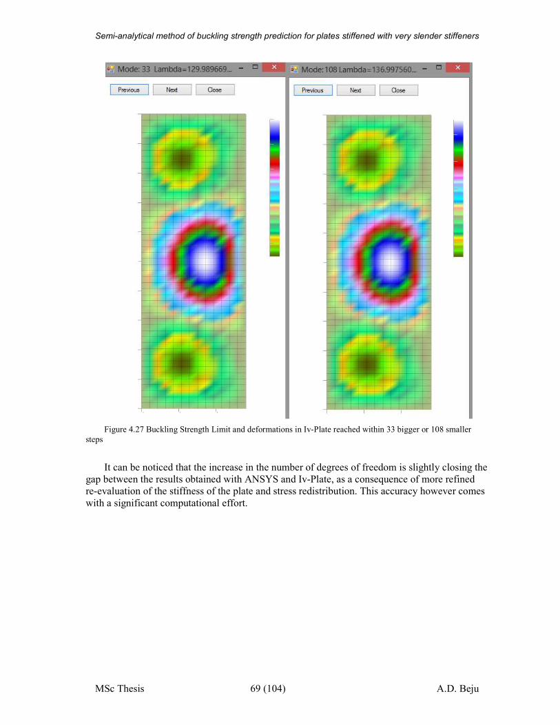
Semi-analytical method of buckling strength prediction for plates stiffened with very slender stiffeners
MSc Thesis 69 (104) A.D. Beju
Figure 4.27 Buckling Strength Limit and deformations in Iv-Plate reached within 33 bigger or 108 smaller
steps
It can be noticed that the increase in the number of degrees of freedom is slightly closing the
gap between the results obtained with ANSYS and Iv-Plate, as a consequence of more refined
re-evaluation of the stiffness of the plate and stress redistribution. This accuracy however comes
with a significant computational effort.
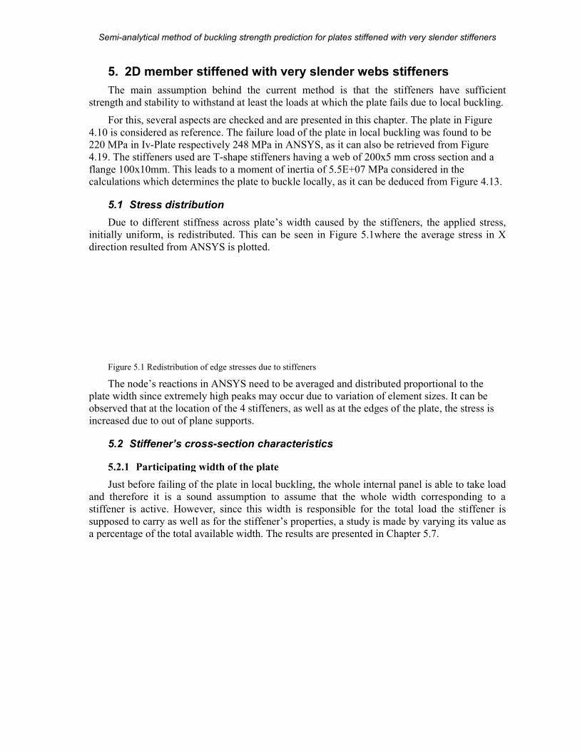
Semi-analytical method of buckling strength prediction
MSc Thesis
5. 2D member stiffened with very slender
The main assumption behind the current
strength and stability to withstand
For this, several aspects are checked and are presented in this chapter.
4.10 is considered as reference. The failure load of the plate in local buckling was found to be
220 MPa in Iv-Plate respectively
4.19. The stiffeners used are T-shape stiffeners having a web of 200x5 mm cross section and a
flange 100x10mm. This leads to a moment of inertia of calculations which determines the plate to buckle locally, as it can be dedu
5.1 Stress distribution
Due to different stiffness across plate’s width
initially uniform, is redistributed. This can
direction resulted from ANSYS is plotted.
Figure 5.1 Redistribution of edge stresses due to stiffeners
The node’s reactions in ANSYS need to be averaged and dist
plate width since extremely high peaks may occur due to variation of element sizes. It can be
observed that at the location of the 4 stiffeners, as well as at the edges of the plate, the stress is
increased due to out of plane supports.
5.2 Stiffener’s cross-section characteristics
5.2.1 Participating width of the plate
Just before failing of the plate in local buckling, the whole internal panel is able to take load
and therefore it is a sound assumption to assume that the whole width corr
stiffener is active. However, since this width is responsible for the total load the stiffener is
supposed to carry as well as for the stiffener’s properties, a study is made by varying its value as
a percentage of the total available width.
analytical method of buckling strength prediction for plates stiffened with very slender stiffeners
70 (104)
2D member stiffened with very slender webs stiffeners
The main assumption behind the current method is that the stiffeners have sufficient
strength and stability to withstand at least the loads at which the plate fails due to local buckling
is, several aspects are checked and are presented in this chapter. The plate in
The failure load of the plate in local buckling was found to be
respectively 248 MPa in ANSYS, as it can also be retrieved from
shape stiffeners having a web of 200x5 mm cross section and a
0mm. This leads to a moment of inertia of 5.5E+07 MPa considered in the which determines the plate to buckle locally, as it can be deduced from
Due to different stiffness across plate’s width caused by the stiffeners, the applied stress,
initially uniform, is redistributed. This can be seen in Figure 5.1where the average stress in X
direction resulted from ANSYS is plotted.
Redistribution of edge stresses due to stiffeners
The node’s reactions in ANSYS need to be averaged and distributed proportional to the
plate width since extremely high peaks may occur due to variation of element sizes. It can be
observed that at the location of the 4 stiffeners, as well as at the edges of the plate, the stress is
upports.
section characteristics
Participating width of the plate
Just before failing of the plate in local buckling, the whole internal panel is able to take load
and therefore it is a sound assumption to assume that the whole width corr
However, since this width is responsible for the total load the stiffener is
supposed to carry as well as for the stiffener’s properties, a study is made by varying its value as
a percentage of the total available width. The results are presented in Chapter 5.7
plates stiffened with very slender stiffeners
A.D. Beju
stiffeners
method is that the stiffeners have sufficient
due to local buckling.
The plate in Figure
The failure load of the plate in local buckling was found to be
, as it can also be retrieved from Figure
shape stiffeners having a web of 200x5 mm cross section and a
MPa considered in the ced from Figure 4.13.
caused by the stiffeners, the applied stress,
where the average stress in X
ributed proportional to the
plate width since extremely high peaks may occur due to variation of element sizes. It can be
observed that at the location of the 4 stiffeners, as well as at the edges of the plate, the stress is
Just before failing of the plate in local buckling, the whole internal panel is able to take load
and therefore it is a sound assumption to assume that the whole width corresponding to a
However, since this width is responsible for the total load the stiffener is
supposed to carry as well as for the stiffener’s properties, a study is made by varying its value as
5.7.
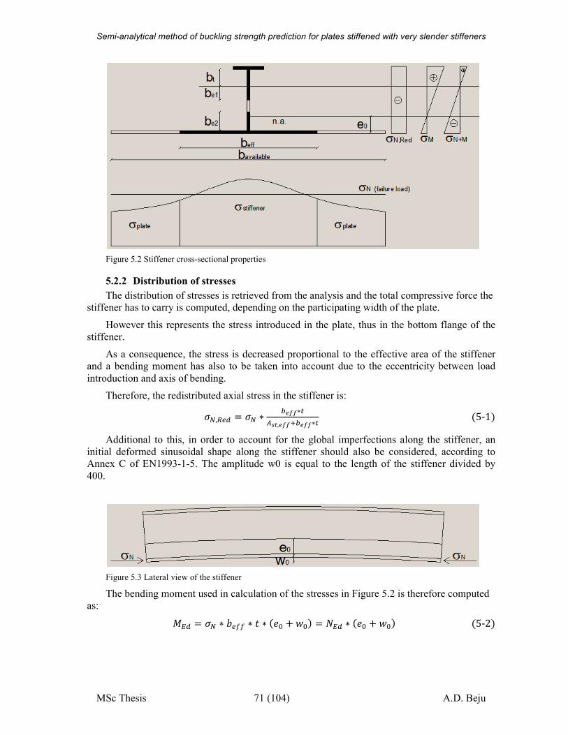
Semi-analytical method of buckling strength prediction for plates stiffened with very slender stiffeners
MSc Thesis 71 (104) A.D. Beju
Figure 5.2 Stiffener cross-sectional properties
5.2.2 Distribution of stresses
The distribution of stresses is retrieved from the analysis and the total compressive force the
stiffener has to carry is computed, depending on the participating width of the plate.
However this represents the stress introduced in the plate, thus in the bottom flange of the
stiffener.
As a consequence, the stress is decreased proportional to the effective area of the stiffener
and a bending moment has also to be taken into account due to the eccentricity between load
introduction and axis of bending.
Therefore, the redistributed axial stress in the stiffener is:
NJ,Ü�À � NJ ∗ �v��∗cçh¸,v����v��∗c �5-1�Additional to this, in order to account for the global imperfections along the stiffener, an
initial deformed sinusoidal shape along the stiffener should also be considered, according to
Annex C of EN1993-1-5. The amplitude w0 is equal to the length of the stiffener divided by
400.
Figure 5.3 Lateral view of the stiffener
The bending moment used in calculation of the stresses in Figure 5.2 is therefore computed
as:
�À � NJ ∗ n�ÍÍ ∗ � ∗ ��% +�%� � ��À ∗ ��% + �%� �5-2�
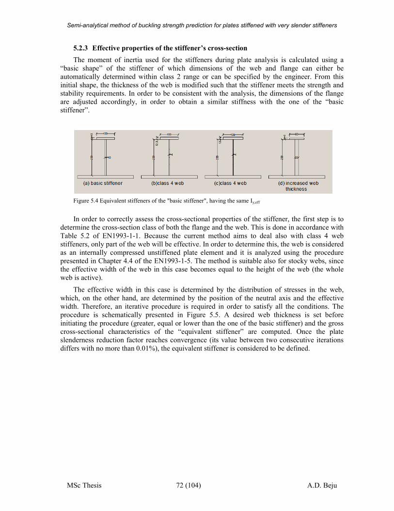
Semi-analytical method of buckling strength prediction for plates stiffened with very slender stiffeners
MSc Thesis 72 (104) A.D. Beju
5.2.3 Effective properties of the stiffener’s cross-section
The moment of inertia used for the stiffeners during plate analysis is calculated using a
“basic shape” of the stiffener of which dimensions of the web and flange can either be
automatically determined within class 2 range or can be specified by the engineer. From this
initial shape, the thickness of the web is modified such that the stiffener meets the strength and
stability requirements. In order to be consistent with the analysis, the dimensions of the flange
are adjusted accordingly, in order to obtain a similar stiffness with the one of the “basic
stiffener”.
Figure 5.4 Equivalent stiffeners of the "basic stiffener", having the same Iy,eff
In order to correctly assess the cross-sectional properties of the stiffener, the first step is to
determine the cross-section class of both the flange and the web. This is done in accordance with
Table 5.2 of EN1993-1-1. Because the current method aims to deal also with class 4 web
stiffeners, only part of the web will be effective. In order to determine this, the web is considered
as an internally compressed unstiffened plate element and it is analyzed using the procedure
presented in Chapter 4.4 of the EN1993-1-5. The method is suitable also for stocky webs, since
the effective width of the web in this case becomes equal to the height of the web (the whole
web is active).
The effective width in this case is determined by the distribution of stresses in the web,
which, on the other hand, are determined by the position of the neutral axis and the effective
width. Therefore, an iterative procedure is required in order to satisfy all the conditions. The
procedure is schematically presented in Figure 5.5. A desired web thickness is set before
initiating the procedure (greater, equal or lower than the one of the basic stiffener) and the gross
cross-sectional characteristics of the “equivalent stiffener” are computed. Once the plate
slenderness reduction factor reaches convergence (its value between two consecutive iterations
differs with no more than 0.01%), the equivalent stiffener is considered to be defined.
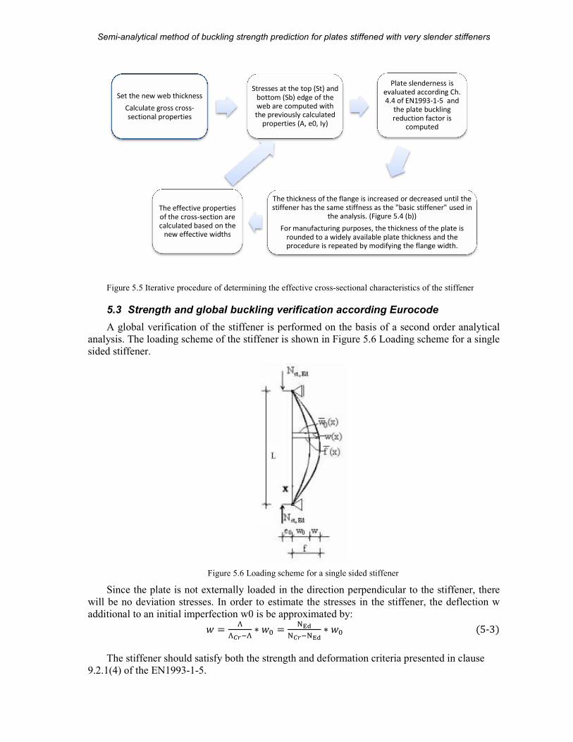
Semi-analytical method of buckling strength prediction
MSc Thesis
Figure 5.5 Iterative procedure of determining
5.3 Strength and global buckling verification accord
A global verification of the stiffener is performed on the basis of a second order analytical
analysis. The loading scheme of the stiffener is shown in
sided stiffener.
Figure
Since the plate is not externally loaded in the direction perpendicular to the stiffener, there
will be no deviation stresses. In order to estimate the stresses
additional to an initial imperfection w0� �
The stiffener should satisfy both the strength and deformation criteria presented in clause
9.2.1(4) of the EN1993-1-5.
The effective properties
of the cross-section are
calculated based on the
new effective widths
Set the new web thickness
Calculate gross cross-
sectional properties
analytical method of buckling strength prediction for plates stiffened with very slender stiffeners
73 (104)
Iterative procedure of determining the effective cross-sectional characteristics of the stiffener
Strength and global buckling verification according Eurocode
A global verification of the stiffener is performed on the basis of a second order analytical
analysis. The loading scheme of the stiffener is shown in Figure 5.6 Loading scheme for a single
Figure 5.6 Loading scheme for a single sided stiffener
Since the plate is not externally loaded in the direction perpendicular to the stiffener, there
In order to estimate the stresses in the stiffener, t
imperfection w0 is be approximated by: ��� T� ∗ �% � ��
� T ��∗ �%
The stiffener should satisfy both the strength and deformation criteria presented in clause
The thickness of the flange is increased or decreased until the
stiffener has the same stiffness as the "basic stiffener" used in
the analysis. (Figure 5.4 (b))
For manufacturing purposes, the thickness of the plate is
rounded to a widely available plate thickness and the
procedure is repeated by modifying the flange width.
The effective properties
section are
calculated based on the
new effective widths
Stresses at the top (St) and
bottom (Sb) edge of the
web are computed with
the previously calculated
properties (A, e0, Iy)
Plate slenderness is
evaluated according Ch.
4.4 of EN1993
the plate buckling
reduction factor is
computed
plates stiffened with very slender stiffeners
A.D. Beju
sectional characteristics of the stiffener
ing Eurocode
A global verification of the stiffener is performed on the basis of a second order analytical
Loading scheme for a single
Since the plate is not externally loaded in the direction perpendicular to the stiffener, there
in the stiffener, the deflection w
�5-3�The stiffener should satisfy both the strength and deformation criteria presented in clause
The thickness of the flange is increased or decreased until the
stiffener has the same stiffness as the "basic stiffener" used in
For manufacturing purposes, the thickness of the plate is
rounded to a widely available plate thickness and the
procedure is repeated by modifying the flange width.
Plate slenderness is
evaluated according Ch.
4.4 of EN1993-1-5 and
the plate buckling
reduction factor is
computed
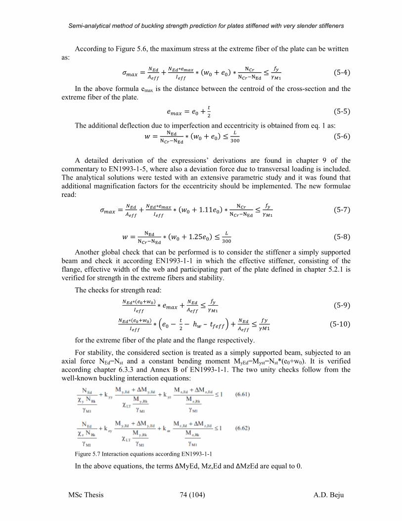
Semi-analytical method of buckling strength prediction for plates stiffened with very slender stiffeners
MSc Thesis 74 (104) A.D. Beju
According to Figure 5.6, the maximum stress at the extreme fiber of the plate can be written
as:
N\-H � Jèéçv�� + Jèé∗�w}~�v�� ∗ ��% + �%� ∗ � � T �� ≤ Íy�Äà �5-4�
In the above formula emax is the distance between the centroid of the cross-section and the
extreme fiber of the plate.
�\-H � �% + c �5-5�The additional deflection due to imperfection and eccentricity is obtained from eq. 1 as: � � ��
� T ��∗ ��% + �%� ≤ �m%% �5-6�
A detailed derivation of the expressions’ derivations are found in chapter 9 of the
commentary to EN1993-1-5, where also a deviation force due to transversal loading is included.
The analytical solutions were tested with an extensive parametric study and it was found that
additional magnification factors for the eccentricity should be implemented. The new formulae
read:
N\-H � Jèéçv�� + Jèé∗�w}~�v�� ∗ ��% + 1.11�%� ∗ � � T �� ≤ Íy�Äà �5-7�
� � ��
� T ��∗ ��% + 1.25�%� ≤ �m%% �5-8�
Another global check that can be performed is to consider the stiffener a simply supported
beam and check it according EN1993-1-1 in which the effective stiffener, consisting of the
flange, effective width of the web and participating part of the plate defined in chapter 5.2.1 is
verified for strength in the extreme fibers and stability.
The checks for strength read:
Jèé∗��^�$^��v�� ∗ �\-H + Jèéçv�� ≤ Íy�Äà �5-9�Jèé∗��^�$^��v�� ∗ �% − c −ℎ$– �Í�ÍÍ� + Jèéçv�� ≤ ÍI��� �5-10�
for the extreme fiber of the plate and the flange respectively.
For stability, the considered section is treated as a simply supported beam, subjected to an
axial force NEd=Nst and a constant bending moment MyEd=Myst=Nst*(e0+w0). It is verified
according chapter 6.3.3 and Annex B of EN1993-1-1. The two unity checks follow from the
well-known buckling interaction equations:
Figure 5.7 Interaction equations according EN1993-1-1
In the above equations, the terms ΔMyEd, Mz,Ed and ΔMzEd are equal to 0.
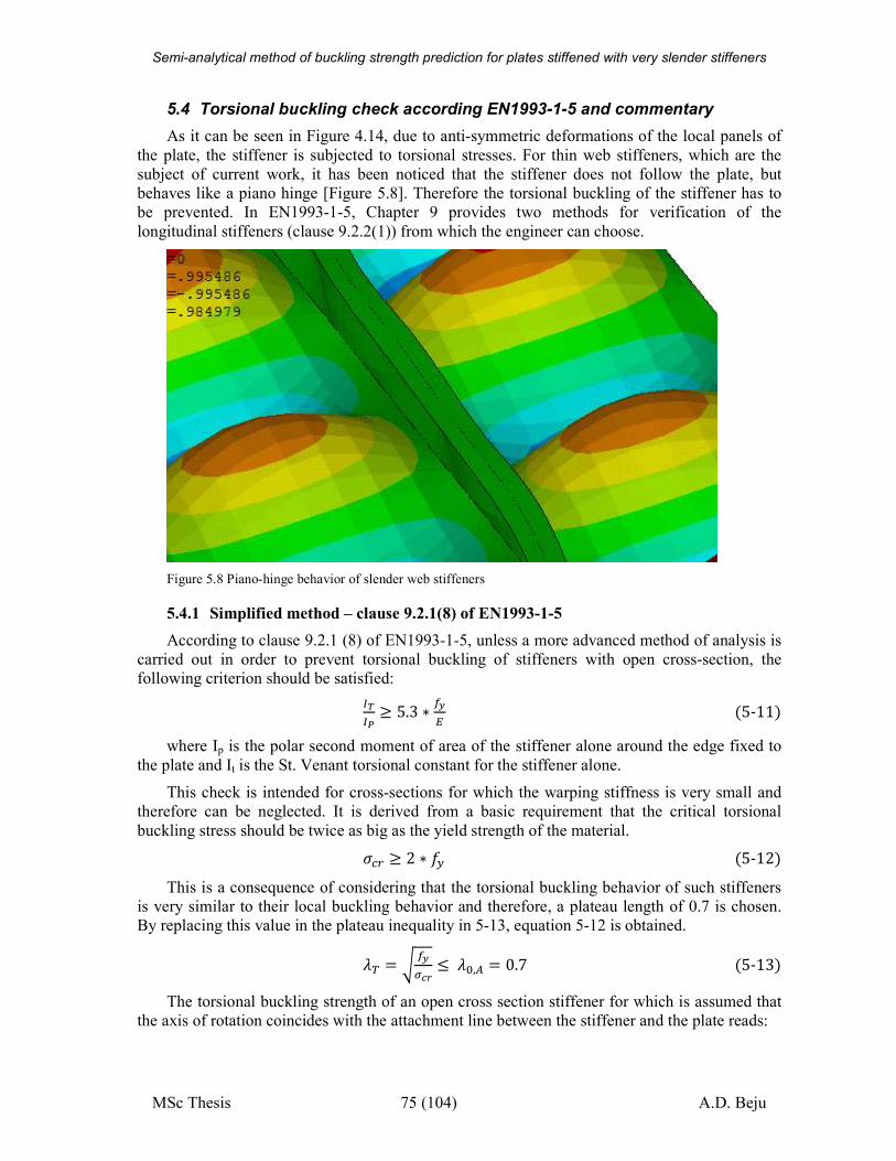
Semi-analytical method of buckling strength prediction for plates stiffened with very slender stiffeners
MSc Thesis 75 (104) A.D. Beju
5.4 Torsional buckling check according EN1993-1-5 and commentary
As it can be seen in Figure 4.14, due to anti-symmetric deformations of the local panels of
the plate, the stiffener is subjected to torsional stresses. For thin web stiffeners, which are the
subject of current work, it has been noticed that the stiffener does not follow the plate, but
behaves like a piano hinge [Figure 5.8]. Therefore the torsional buckling of the stiffener has to
be prevented. In EN1993-1-5, Chapter 9 provides two methods for verification of the
longitudinal stiffeners (clause 9.2.2(1)) from which the engineer can choose.
Figure 5.8 Piano-hinge behavior of slender web stiffeners
5.4.1 Simplified method – clause 9.2.1(8) of EN1993-1-5
According to clause 9.2.1 (8) of EN1993-1-5, unless a more advanced method of analysis is
carried out in order to prevent torsional buckling of stiffeners with open cross-section, the
following criterion should be satisfied:
���� ≥ 5.3 ∗ Íy� �5-11�where Ip is the polar second moment of area of the stiffener alone around the edge fixed to
the plate and It is the St. Venant torsional constant for the stiffener alone.
This check is intended for cross-sections for which the warping stiffness is very small and
therefore can be neglected. It is derived from a basic requirement that the critical torsional
buckling stress should be twice as big as the yield strength of the material. N�) ≥ 2 ∗ �I �5-12�This is a consequence of considering that the torsional buckling behavior of such stiffeners
is very similar to their local buckling behavior and therefore, a plateau length of 0.7 is chosen.
By replacing this value in the plateau inequality in 5-13, equation 5-12 is obtained.
�D � o ÍyuÒ ≤�%,ç � 0.7 �5-13�The torsional buckling strength of an open cross section stiffener for which is assumed that
the axis of rotation coincides with the attachment line between the stiffener and the plate reads:
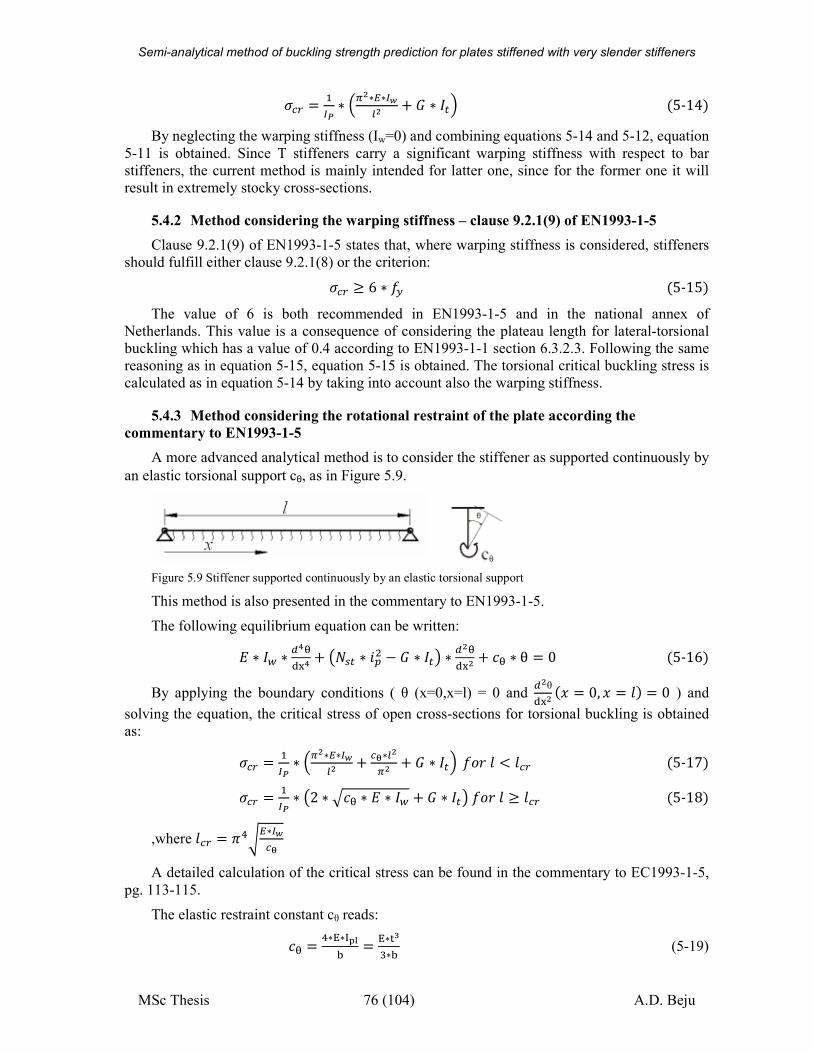
Semi-analytical method of buckling strength prediction for plates stiffened with very slender stiffeners
MSc Thesis 76 (104) A.D. Beju
N�) � ��� ∗ �#∗�∗�ój# + W ∗ ãc� �5-14�By neglecting the warping stiffness (Iw=0) and combining equations 5-14 and 5-12, equation
5-11 is obtained. Since T stiffeners carry a significant warping stiffness with respect to bar
stiffeners, the current method is mainly intended for latter one, since for the former one it will
result in extremely stocky cross-sections.
5.4.2 Method considering the warping stiffness – clause 9.2.1(9) of EN1993-1-5
Clause 9.2.1(9) of EN1993-1-5 states that, where warping stiffness is considered, stiffeners
should fulfill either clause 9.2.1(8) or the criterion: N�) ≥ 6 ∗ �I �5-15�The value of 6 is both recommended in EN1993-1-5 and in the national annex of
Netherlands. This value is a consequence of considering the plateau length for lateral-torsional
buckling which has a value of 0.4 according to EN1993-1-1 section 6.3.2.3. Following the same
reasoning as in equation 5-15, equation 5-15 is obtained. The torsional critical buckling stress is
calculated as in equation 5-14 by taking into account also the warping stiffness.
5.4.3 Method considering the rotational restraint of the plate according the
commentary to EN1993-1-5
A more advanced analytical method is to consider the stiffener as supported continuously by
an elastic torsional support cθ, as in Figure 5.9.
Figure 5.9 Stiffener supported continuously by an elastic torsional support
This method is also presented in the commentary to EN1993-1-5.
The following equilibrium equation can be written:
� ∗ ã$ ∗ À¬���¬ + p�'c ∗ �( − W ∗ ãcq ∗ À#�
��# + �� ∗ θ � 0 �5-16�By applying the boundary conditions ( θ (x=0,x=l) = 0 and
À#θ
��# �F � 0, F � �� � 0 ) and
solving the equation, the critical stress of open cross-sections for torsional buckling is obtained
as:
N�) � ��� ∗ �#∗�∗�ój# + ��∗j#�# + W ∗ ãc� ���� < ��) �5-17�N�) � ��� ∗ p2 ∗ Ó�� ∗ � ∗ ã$ + W ∗ ãcq���� ≥ ��) �5-18�
,where ��) � Ë/o�∗�ó��
A detailed calculation of the critical stress can be found in the commentary to EC1993-1-5,
pg. 113-115.
The elastic restraint constant cθ reads:
�� � /∗�∗ú¦û�
� �∗�dm∗� (5-19)
Semi-analytical method of buckling strength prediction for plates stiffened with very slender stiffeners
MSc Thesis 77 (104) A.D. Beju
However, for longitudinal stiffeners, the effect of the torsional restraint is affected by the
amount of stress in the plate. A study has been performed by Darko Beg in [15] in order to
account for the reduction in the elastic restraint constant due to longitudinal stresses and a factor
of 3 seems to be adequate, as also suggested in [14]. More detailed analytical approximations of
experimental simulations using ABAQUS are also found in [15] leading to reduction factors that
depend on all the main parameters of the plate, such as α , b/t, σ/fy.
Therefore, the reduced elastic restraint constant becomes:
�� � �∗�dm∗� ∗ f��α� ∗ f t�� , �Ý�z �5-20�By neglecting the small favorable influences of the plate, the safe-sided simplification, it
reads:
�� � �∗�dm∗� ∗ eTt Ãd^. ∗!"∗#��z �5-21�Since this method takes into account the warping stiffness of the stiffener as well, the
requirement to be fulfilled is as in equation 5-15, namely: N�) ≥ 6 ∗ �I �5-22�In all the expressions in chapter 5.4, Ip, It and Iw are calculated for the effective cross-section
of the stiffener alone around the axis connecting the stiffener web and the plate.
5.5 Local behavior of the web
As the web of the stiffener becomes thinner and thinner, its slenderness increases and the local buckling of the web due to plate and flange induced stresses is going to be governing. In
order to evaluate the web’s local behavior, the stresses across the web height due to flange and
plate action need to be evaluated. Because in the out-of-plane direction the web stiffness is
significantly smaller than the one of the flange and negligible with respect to the one of the plate,
the web will be treated like a simply supported plate, biaxially loaded. Across the web height the
loads are induced by the flange/plate action while in the longitudinal direction, the stress is
caused by the redistribution of loading from the plate to the flange.
If the plate has the necessary capacity to withstand these loads without buckling, with a
magnitude correspondent to the failure stress of the plate, can be concluded that the stiffener will
not lose its capacity before the local failure occurs.
5.5.1 Flange induced buckling according EN1993-1-5
One method of ensuring that the web of the stiffener is strong enough to prevent the flange
from buckling into it is presented in chapter 8 of the EN1993-1-5 under the name of “flange
induced buckling”. The uniformly distributed radial stress in the web at yielding of the web is
estimated computed as:
N] � 3 ∗ ç�Òçó ∗ Íy�#� �5-23�Limiting this stress to the critical buckling stress across the web height
N�),$ � �#�có#� ��TU#�%ó# �5-24�, the equation presented in chapter 8 of the EN1993-1-5 is obtained, namely:
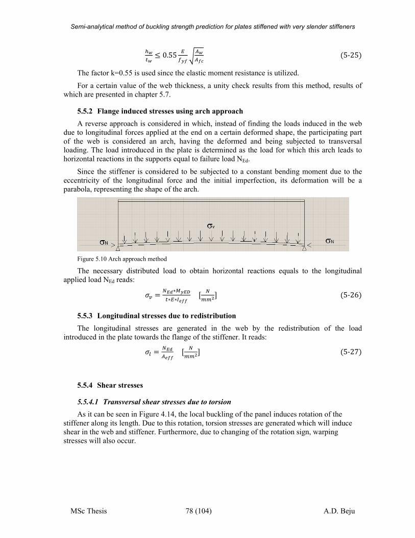
Semi-analytical method of buckling strength prediction for plates stiffened with very slender stiffeners
MSc Thesis 78 (104) A.D. Beju
%ócó ≤ 0.55 �Íy�oçóç�Ò �5-25�The factor k=0.55 is used since the elastic moment resistance is utilized.
For a certain value of the web thickness, a unity check results from this method, results of
which are presented in chapter 5.7.
5.5.2 Flange induced stresses using arch approach
A reverse approach is considered in which, instead of finding the loads induced in the web
due to longitudinal forces applied at the end on a certain deformed shape, the participating part
of the web is considered an arch, having the deformed and being subjected to transversal loading. The load introduced in the plate is determined as the load for which this arch leads to
horizontal reactions in the supports equal to failure load NEd.
Since the stiffener is considered to be subjected to a constant bending moment due to the
eccentricity of the longitudinal force and the initial imperfection, its deformation will be a
parabola, representing the shape of the arch.
Figure 5.10 Arch approach method
The necessary distributed load to obtain horizontal reactions equals to the longitudinal
applied load NEd reads:
N] � Jèé∗�yè&c∗�∗�v�� � J\\#� �5-26�5.5.3 Longitudinal stresses due to redistribution
The longitudinal stresses are generated in the web by the redistribution of the load
introduced in the plate towards the flange of the stiffener. It reads:
Nj � Jèéçv�� � J\\#� �5-27�
5.5.4 Shear stresses
5.5.4.1 Transversal shear stresses due to torsion
As it can be seen in Figure 4.14, the local buckling of the panel induces rotation of the
stiffener along its length. Due to this rotation, torsion stresses are generated which will induce
shear in the web and stiffener. Furthermore, due to changing of the rotation sign, warping
stresses will also occur.
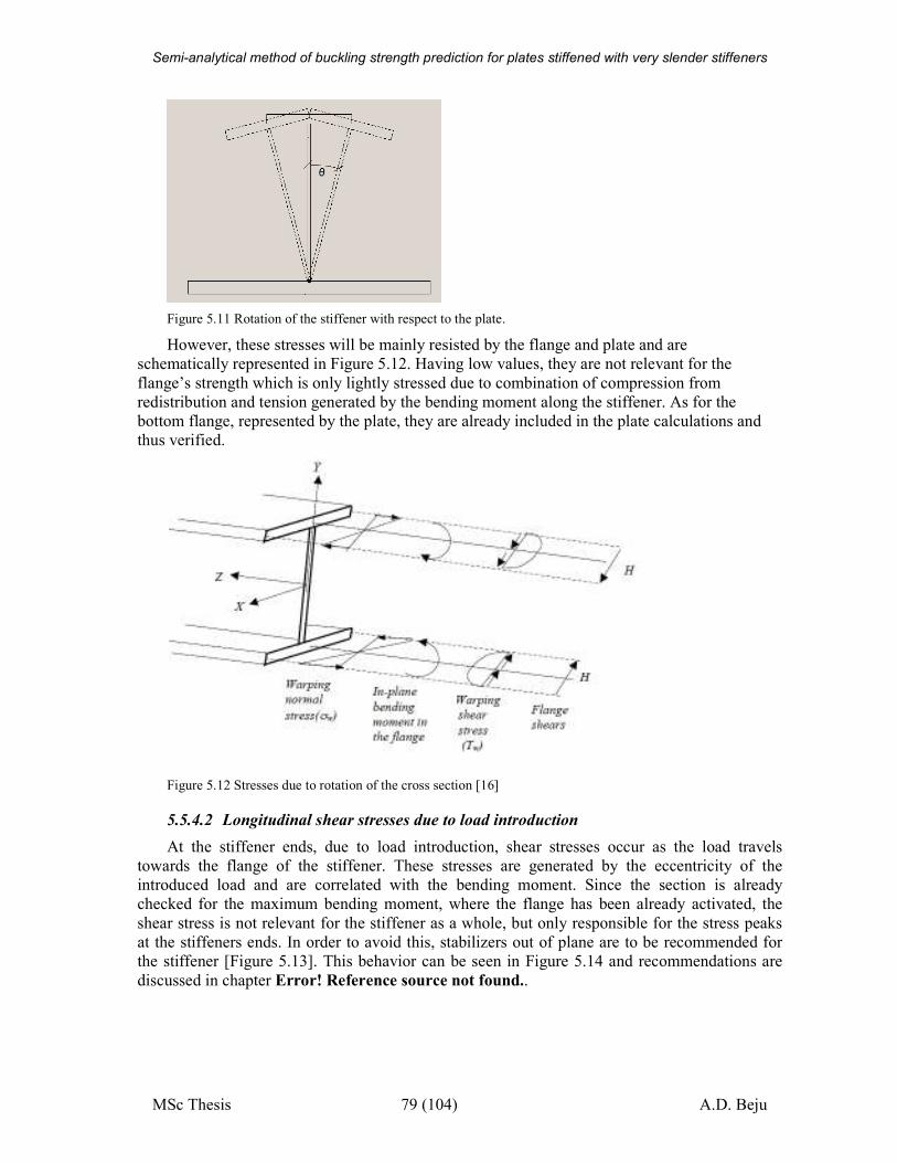
Semi-analytical method of buckling strength prediction for plates stiffened with very slender stiffeners
MSc Thesis 79 (104) A.D. Beju
Figure 5.11 Rotation of the stiffener with respect to the plate.
However, these stresses will be mainly resisted by the flange and plate and are
schematically represented in Figure 5.12. Having low values, they are not relevant for the
flange’s strength which is only lightly stressed due to combination of compression from
redistribution and tension generated by the bending moment along the stiffener. As for the
bottom flange, represented by the plate, they are already included in the plate calculations and
thus verified.
Figure 5.12 Stresses due to rotation of the cross section [16]
5.5.4.2 Longitudinal shear stresses due to load introduction
At the stiffener ends, due to load introduction, shear stresses occur as the load travels
towards the flange of the stiffener. These stresses are generated by the eccentricity of the
introduced load and are correlated with the bending moment. Since the section is already
checked for the maximum bending moment, where the flange has been already activated, the
shear stress is not relevant for the stiffener as a whole, but only responsible for the stress peaks
at the stiffeners ends. In order to avoid this, stabilizers out of plane are to be recommended for
the stiffener [Figure 5.13]. This behavior can be seen in Figure 5.14 and recommendations are
discussed in chapter Error! Reference source not found..
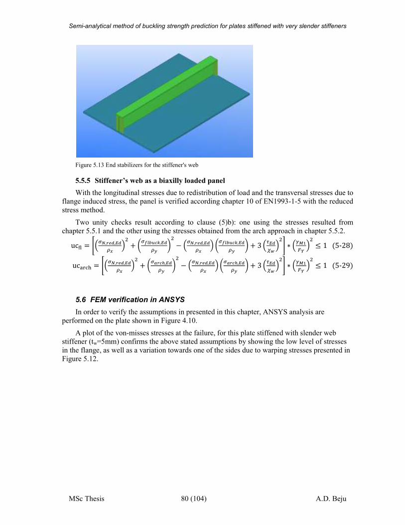
Semi-analytical method of buckling strength prediction for plates stiffened with very slender stiffeners
MSc Thesis 80 (104) A.D. Beju
Figure 5.13 End stabilizers for the stiffener's web
5.5.5 Stiffener’s web as a biaxilly loaded panel
With the longitudinal stresses due to redistribution of load and the transversal stresses due to
flange induced stress, the panel is verified according chapter 10 of EN1993-1-5 with the reduced
stress method.
Two unity checks result according to clause (5)b): one using the stresses resulted from
chapter 5.5.1 and the other using the stresses obtained from the arch approach in chapter 5.5.2.
uc(� � ñ uÁ, vé,èéë~ � + tu�l|íÒk,èéëy z − uÁ, vé,èéë~ � tu�l|íÒk,èéëy z + 3 ðèéòó� ô ∗ �ÄÃx´ � ≤ 1�5-28�uc)*ö+ � ñ uÁ, vé,èéë~ � + tu} Ò,,èéëy z − uÁ, vé,èéë~ � tu} Ò,,èéëy z + 3 ðèéòó� ô ∗ �ÄÃx´ � ≤ 1�5-29�
5.6 FEM verification in ANSYS
In order to verify the assumptions in presented in this chapter, ANSYS analysis are
performed on the plate shown in Figure 4.10.
A plot of the von-misses stresses at the failure, for this plate stiffened with slender web
stiffener (tw=5mm) confirms the above stated assumptions by showing the low level of stresses
in the flange, as well as a variation towards one of the sides due to warping stresses presented in
Figure 5.12.
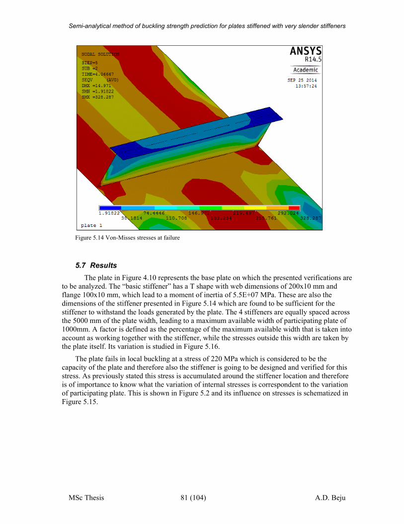
Semi-analytical method of buckling strength prediction for plates stiffened with very slender stiffeners
MSc Thesis 81 (104) A.D. Beju
Figure 5.14 Von-Misses stresses at failure
5.7 Results
The plate in Figure 4.10 represents the base plate on which the presented verifications are
to be analyzed. The “basic stiffener” has a T shape with web dimensions of 200x10 mm and
flange 100x10 mm, which lead to a moment of inertia of 5.5E+07 MPa. These are also the
dimensions of the stiffener presented in Figure 5.14 which are found to be sufficient for the
stiffener to withstand the loads generated by the plate. The 4 stiffeners are equally spaced across
the 5000 mm of the plate width, leading to a maximum available width of participating plate of
1000mm. A factor is defined as the percentage of the maximum available width that is taken into
account as working together with the stiffener, while the stresses outside this width are taken by
the plate itself. Its variation is studied in Figure 5.16.
The plate fails in local buckling at a stress of 220 MPa which is considered to be the
capacity of the plate and therefore also the stiffener is going to be designed and verified for this
stress. As previously stated this stress is accumulated around the stiffener location and therefore
is of importance to know what the variation of internal stresses is correspondent to the variation
of participating plate. This is shown in Figure 5.2 and its influence on stresses is schematized in
Figure 5.15.
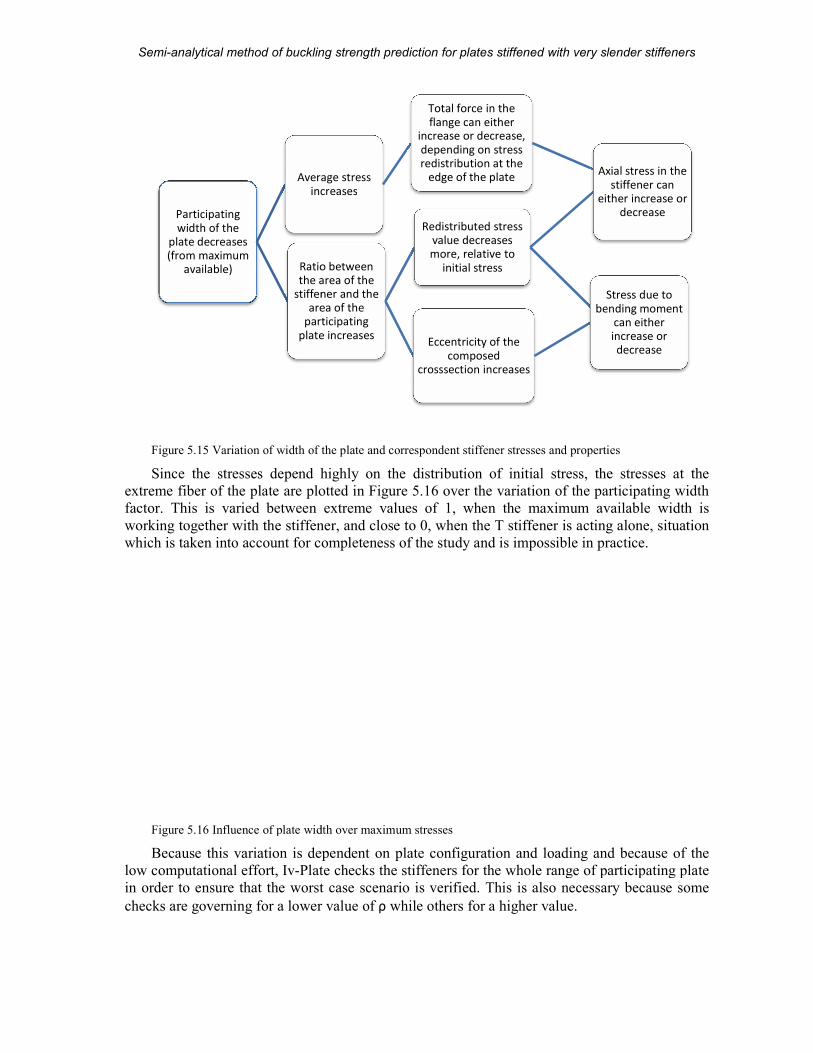
Semi-analytical method of buckling strength prediction
MSc Thesis
Figure 5.15 Variation of width of the plate and
Since the stresses depend highly on the distribution of initial stress, t
extreme fiber of the plate are plotted in
factor. This is varied between extreme values of 1, when the maximum available width is
working together with the stiffener, and close to 0, when the T stiffener is acting alone
which is taken into account for completeness of the study
Figure 5.16 Influence of plate width over maximum stresses
Because this variation is dependent on plate configuration and loading and because of the
low computational effort, Iv-Plate
in order to ensure that the worst case scenario is verified. This is also necessary because some
checks are governing for a lower value of
Participating
width of the
plate decreases
(from maximum
available)
Average stress
increases
Ratio between
the area of the
stiffener and the
area of the
participating
plate increases
analytical method of buckling strength prediction for plates stiffened with very slender stiffeners
82 (104)
width of the plate and correspondent stiffener stresses and properties
Since the stresses depend highly on the distribution of initial stress, the stresses at the
extreme fiber of the plate are plotted in Figure 5.16 over the variation of the participat
factor. This is varied between extreme values of 1, when the maximum available width is
working together with the stiffener, and close to 0, when the T stiffener is acting alone
which is taken into account for completeness of the study and is impossible in practice.
Influence of plate width over maximum stresses
this variation is dependent on plate configuration and loading and because of the
Plate checks the stiffeners for the whole range of participating plate
in order to ensure that the worst case scenario is verified. This is also necessary because some
checks are governing for a lower value of ρ while others for a higher value.
Average stress
increases
Total force in the
flange can either
increase or decrease,
depending on stress
redistribution at the
edge of the plate
Ratio between
the area of the
stiffener and the
area of the
participating
plate increases
Redistributed stress
value decreases
more, relative to
initial stress
Axial stress in the
either increase or
Eccentricity of the
composed
crosssection increases
Stress due to
bending moment
plates stiffened with very slender stiffeners
A.D. Beju
properties
he stresses at the
over the variation of the participating width
factor. This is varied between extreme values of 1, when the maximum available width is
working together with the stiffener, and close to 0, when the T stiffener is acting alone, situation
and is impossible in practice.
this variation is dependent on plate configuration and loading and because of the
checks the stiffeners for the whole range of participating plate
in order to ensure that the worst case scenario is verified. This is also necessary because some
Axial stress in the
stiffener can
either increase or
decrease
Stress due to
bending moment
can either
increase or
decrease
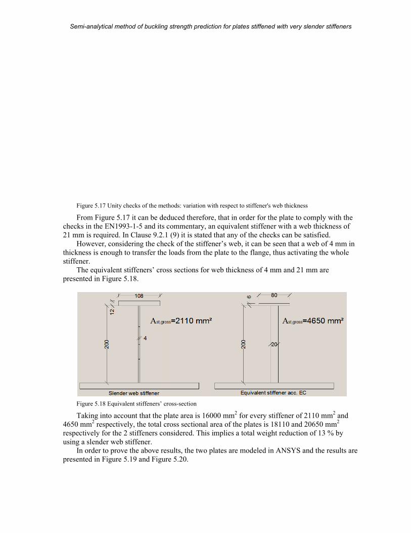
Semi-analytical method of buckling strength prediction
MSc Thesis
Figure 5.17 Unity checks of the methods: variation with respect to stiffener's web thickness
From Figure 5.17 it can be deduced therefore, that
checks in the EN1993-1-5 and its commentary, an equivalent stiffener with a web thickness of
21 mm is required. In Clause 9.2.1 (9) it is stated that any of the checks can be satisfied.
However, considering the che
thickness is enough to transfer the loads from the plate to the flange, thus activating the whole
stiffener.
The equivalent stiffeners’ cross sections for web thickness of 4 mm and 21 mm are
presented in Figure 5.18.
Figure 5.18 Equivalent stiffeners’ cross
Taking into account that the plate area is 16000 mm
4650 mm2 respectively, the total cross sectional area of the plates is 18110 and 20650 mm
respectively for the 2 stiffeners considered. This implies a total weight reduction of 13 % by
using a slender web stiffener. In order to prove the above results
presented in Figure 5.19 and Figure
analytical method of buckling strength prediction for plates stiffened with very slender stiffeners
83 (104)
Unity checks of the methods: variation with respect to stiffener's web thickness
it can be deduced therefore, that in order for the plate to comply with the
5 and its commentary, an equivalent stiffener with a web thickness of
21 mm is required. In Clause 9.2.1 (9) it is stated that any of the checks can be satisfied.
However, considering the check of the stiffener’s web, it can be seen that a web of 4 mm in
thickness is enough to transfer the loads from the plate to the flange, thus activating the whole
The equivalent stiffeners’ cross sections for web thickness of 4 mm and 21 mm are
Equivalent stiffeners’ cross-section
the plate area is 16000 mm2 for every stiffener of 2110 mm
ively, the total cross sectional area of the plates is 18110 and 20650 mm
respectively for the 2 stiffeners considered. This implies a total weight reduction of 13 % by
the above results, the two plates are modeled in ANSYS and the results are
Figure 5.20.
plates stiffened with very slender stiffeners
A.D. Beju
Unity checks of the methods: variation with respect to stiffener's web thickness
in order for the plate to comply with the
5 and its commentary, an equivalent stiffener with a web thickness of
21 mm is required. In Clause 9.2.1 (9) it is stated that any of the checks can be satisfied.
ck of the stiffener’s web, it can be seen that a web of 4 mm in
thickness is enough to transfer the loads from the plate to the flange, thus activating the whole
The equivalent stiffeners’ cross sections for web thickness of 4 mm and 21 mm are
for every stiffener of 2110 mm2 and
ively, the total cross sectional area of the plates is 18110 and 20650 mm2
respectively for the 2 stiffeners considered. This implies a total weight reduction of 13 % by
deled in ANSYS and the results are
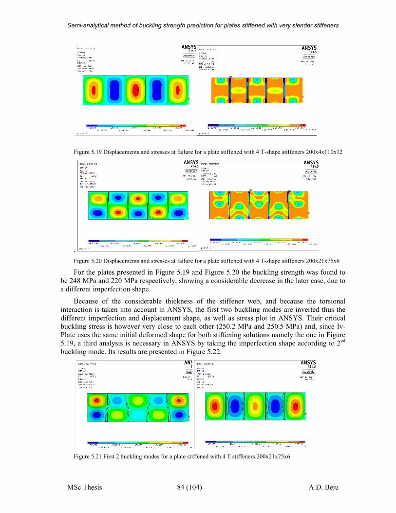
Semi-analytical method of buckling strength prediction for plates stiffened with very slender stiffeners
MSc Thesis 84 (104) A.D. Beju
Figure 5.19 Displacements and stresses at failure for a plate stiffened with 4 T-shape stiffeners 200x4x110x12
.
Figure 5.20 Displacements and stresses at failure for a plate stiffened with 4 T-shape stiffeners 200x21x75x6
For the plates presented in Figure 5.19 and Figure 5.20 the buckling strength was found to
be 248 MPa and 220 MPa respectively, showing a considerable decrease in the later case, due to
a different imperfection shape.
Because of the considerable thickness of the stiffener web, and because the torsional
interaction is taken into account in ANSYS, the first two buckling modes are inverted thus the
different imperfection and displacement shape, as well as stress plot in ANSYS. Their critical
buckling stress is however very close to each other (250.2 MPa and 250.5 MPa) and, since Iv-
Plate uses the same initial deformed shape for both stiffening solutions namely the one in Figure
5.19, a third analysis is necessary in ANSYS by taking the imperfection shape according to 2nd
buckling mode. Its results are presented in Figure 5.22.
Figure 5.21 First 2 buckling modes for a plate stiffened with 4 T stiffeners 200x21x75x6
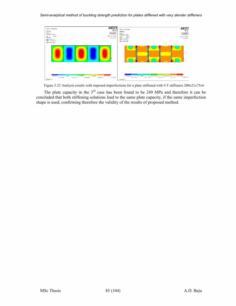
Semi-analytical method of buckling strength prediction for plates stiffened with very slender stiffeners
MSc Thesis 85 (104) A.D. Beju
Figure 5.22 Analysis results with imposed imperfections for a plate stiffened with 4 T stiffeners 200x21x75x6
The plate capacity in the 3rd
case has been found to be 249 MPa and therefore it can be
concluded that both stiffening solutions lead to the same plate capacity, if the same imperfection
shape is used, confirming therefore the validity of the results of proposed method.
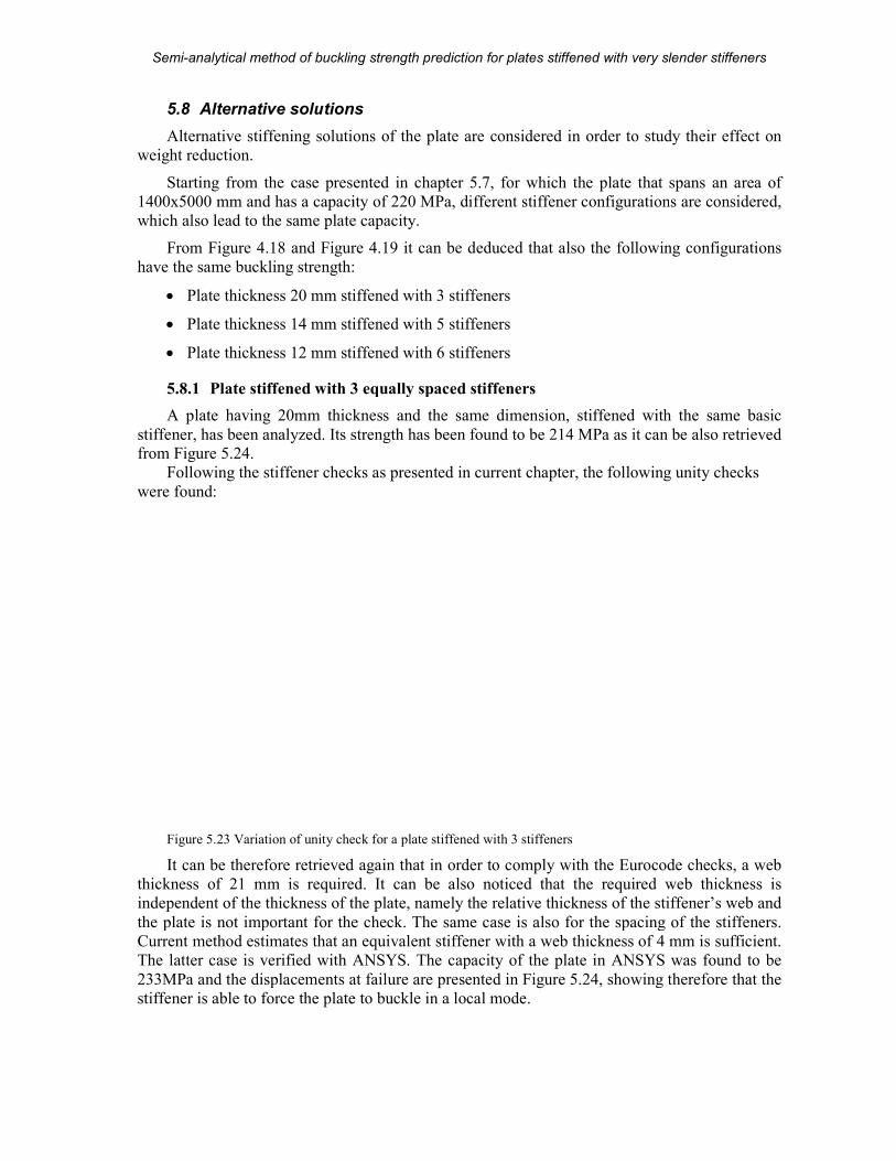
Semi-analytical method of buckling strength prediction
MSc Thesis
5.8 Alternative solutions
Alternative stiffening solutions of the plate are considered
weight reduction.
Starting from the case presented in chapter
1400x5000 mm and has a capacity of 220 MPa, different stiffener configurations are c
which also lead to the same plate capacity.
From Figure 4.18 and Figure
have the same buckling strength:
• Plate thickness 20 mm stif
• Plate thickness 14 mm stiffened with 5 stiffeners
• Plate thickness 12 mm stiffened with 6 stiffeners
5.8.1 Plate stiffened with 3 equally spaced stiffeners
A plate having 20mm thickness and the same dimension, stiffened with the same basic
stiffener, has been analyzed. Its strength has been found to be 214 MPa as it can be also retrieved from Figure 5.24.
Following the stiffener checks as presented in current chapter, the following unity checks
were found:
Figure 5.23 Variation of unity check for a plate stiffened with 3 stiffeners
It can be therefore retrieved again that in order to comply with the Eurocode checks, a web
thickness of 21 mm is required. It can be al
independent of the thickness of the plate, namely the relative thickness of the stiffener’s web and
the plate is not important for the check. The same case is also for the spacing of the stiffeners.
Current method estimates that an equivalent stiffener with a web thickness of 4 mm is sufficient.
The latter case is verified with ANSYS
233MPa and the displacements at failure
stiffener is able to force the plate to buckle in a local mode.
analytical method of buckling strength prediction for plates stiffened with very slender stiffeners
86 (104)
Alternative solutions
Alternative stiffening solutions of the plate are considered in order to study their effect on
Starting from the case presented in chapter 5.7, for which the plate that spans an area of
1400x5000 mm and has a capacity of 220 MPa, different stiffener configurations are c
which also lead to the same plate capacity.
Figure 4.19 it can be deduced that also the following configurations
have the same buckling strength:
mm stiffened with 3 stiffeners
Plate thickness 14 mm stiffened with 5 stiffeners
Plate thickness 12 mm stiffened with 6 stiffeners
Plate stiffened with 3 equally spaced stiffeners
A plate having 20mm thickness and the same dimension, stiffened with the same basic
stiffener, has been analyzed. Its strength has been found to be 214 MPa as it can be also retrieved
Following the stiffener checks as presented in current chapter, the following unity checks
Variation of unity check for a plate stiffened with 3 stiffeners
It can be therefore retrieved again that in order to comply with the Eurocode checks, a web
thickness of 21 mm is required. It can be also noticed that the required web thickness is
independent of the thickness of the plate, namely the relative thickness of the stiffener’s web and
the plate is not important for the check. The same case is also for the spacing of the stiffeners.
hod estimates that an equivalent stiffener with a web thickness of 4 mm is sufficient.
The latter case is verified with ANSYS. The capacity of the plate in ANSYS was found to be
displacements at failure are presented in Figure 5.24, showing therefore that the
stiffener is able to force the plate to buckle in a local mode.
plates stiffened with very slender stiffeners
A.D. Beju
in order to study their effect on
, for which the plate that spans an area of
1400x5000 mm and has a capacity of 220 MPa, different stiffener configurations are considered,
it can be deduced that also the following configurations
A plate having 20mm thickness and the same dimension, stiffened with the same basic
stiffener, has been analyzed. Its strength has been found to be 214 MPa as it can be also retrieved
Following the stiffener checks as presented in current chapter, the following unity checks
It can be therefore retrieved again that in order to comply with the Eurocode checks, a web
so noticed that the required web thickness is
independent of the thickness of the plate, namely the relative thickness of the stiffener’s web and
the plate is not important for the check. The same case is also for the spacing of the stiffeners.
hod estimates that an equivalent stiffener with a web thickness of 4 mm is sufficient.
The capacity of the plate in ANSYS was found to be
, showing therefore that the
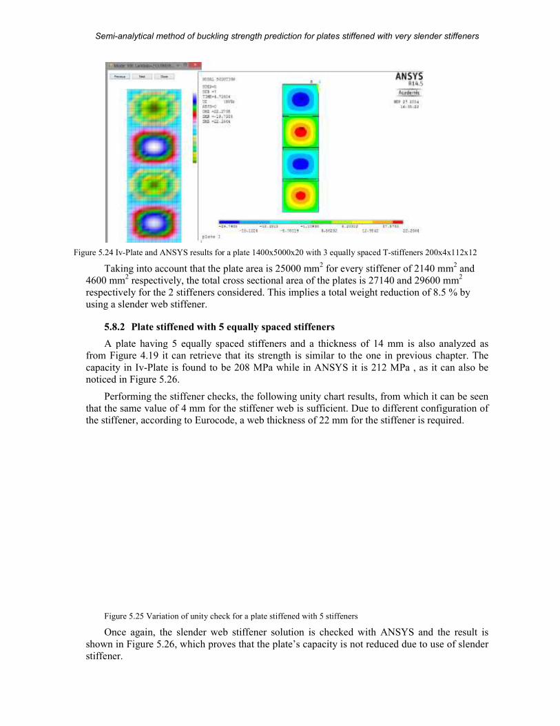
Semi-analytical method of buckling strength prediction
MSc Thesis
Figure 5.24 Iv-Plate and ANSYS results for a plate 1400x5000x20
Taking into account that the plate area is 25000 mm
4600 mm2 respectively, the total cross sectional area of the plates is
respectively for the 2 stiffeners considered. This
using a slender web stiffener.
5.8.2 Plate stiffened with 5 equally spaced stiffeners
A plate having 5 equally spaced stiffeners and a thickness of 14 mm is also analyzed as
from Figure 4.19 it can retrieve that its strength is similar to the one in previous chapter. The
capacity in Iv-Plate is found to be 208 MPa while in ANSYS it is 212 MPa , as it can also be
noticed in Figure 5.26.
Performing the stiffener checks,
that the same value of 4 mm for the stiffener web is sufficient. Due to different configuration of
the stiffener, according to Eurocode, a web thickness of 22 mm for the stiffener is required.
Figure 5.25 Variation of unity check for a plate stiffened with 5 stiffeners
Once again, the slender web stiffener solution is checked with ANSYS and the result is
shown in Figure 5.26, which proves
stiffener.
analytical method of buckling strength prediction for plates stiffened with very slender stiffeners
87 (104)
ANSYS results for a plate 1400x5000x20 with 3 equally spaced T-stiffeners 200x4x112x12
Taking into account that the plate area is 25000 mm2 for every stiffener of 2140 mm
respectively, the total cross sectional area of the plates is 27140 and 29600
respectively for the 2 stiffeners considered. This implies a total weight reduction of
Plate stiffened with 5 equally spaced stiffeners
A plate having 5 equally spaced stiffeners and a thickness of 14 mm is also analyzed as
it can retrieve that its strength is similar to the one in previous chapter. The
is found to be 208 MPa while in ANSYS it is 212 MPa , as it can also be
Performing the stiffener checks, the following unity chart results, from which it can be seen
that the same value of 4 mm for the stiffener web is sufficient. Due to different configuration of
the stiffener, according to Eurocode, a web thickness of 22 mm for the stiffener is required.
Variation of unity check for a plate stiffened with 5 stiffeners
Once again, the slender web stiffener solution is checked with ANSYS and the result is
proves that the plate’s capacity is not reduced due to use of slender
plates stiffened with very slender stiffeners
A.D. Beju
stiffeners 200x4x112x12
for every stiffener of 2140 mm2 and
29600 mm2
implies a total weight reduction of 8.5 % by
A plate having 5 equally spaced stiffeners and a thickness of 14 mm is also analyzed as
it can retrieve that its strength is similar to the one in previous chapter. The
is found to be 208 MPa while in ANSYS it is 212 MPa , as it can also be
the following unity chart results, from which it can be seen
that the same value of 4 mm for the stiffener web is sufficient. Due to different configuration of
the stiffener, according to Eurocode, a web thickness of 22 mm for the stiffener is required.
Once again, the slender web stiffener solution is checked with ANSYS and the result is
that the plate’s capacity is not reduced due to use of slender
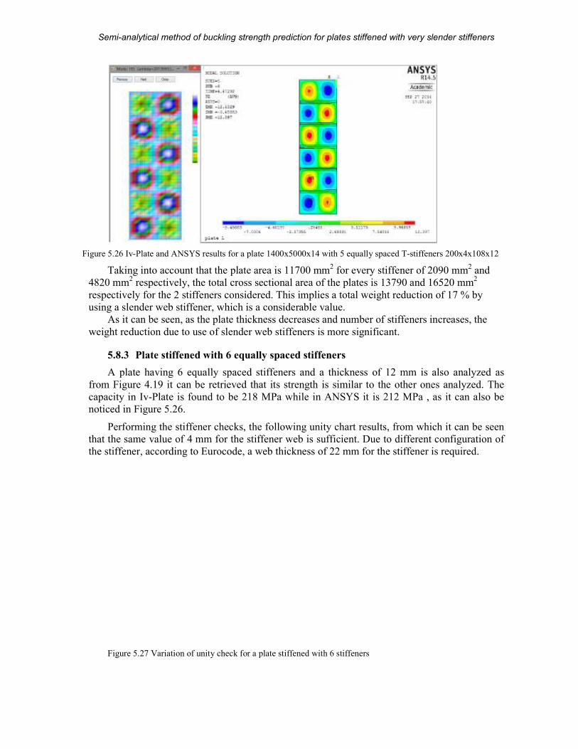
Semi-analytical method of buckling strength prediction
MSc Thesis
Figure 5.26 Iv-Plate and ANSYS results for a plate 1400x5000x
Taking into account that the plate area is 11700 mm
4820 mm2 respectively, the total cross sectional a
respectively for the 2 stiffeners considered. This implies a total weight reduction of 17 % by
using a slender web stiffener, which is a considerable value.
As it can be seen, as the plate thickness decreases and nu
weight reduction due to use of slender web stiffeners is more significant.
5.8.3 Plate stiffened with 6 equally spaced stiffeners
A plate having 6 equally spaced stiffeners and a thickness of 12 mm is also analyzed as
from Figure 4.19 it can be retrieved that its strength is similar to the other ones analyzed. The
capacity in Iv-Plate is found to be 2
noticed in Figure 5.26.
Performing the stiffener checks, the following unity chart results, from which it can be seen
that the same value of 4 mm for the stiffener web is sufficient. Due to different configuration of
the stiffener, according to Eurocode, a web thickness of 22 mm
Figure 5.27 Variation of unity check for a plate stiffened with 6 stiffeners
analytical method of buckling strength prediction for plates stiffened with very slender stiffeners
88 (104)
and ANSYS results for a plate 1400x5000x14 with 5 equally spaced T-stiffeners 200x4x108x12
Taking into account that the plate area is 11700 mm2 for every stiffener of 2090 mm
respectively, the total cross sectional area of the plates is 13790 and 16520 mm
respectively for the 2 stiffeners considered. This implies a total weight reduction of 17 % by
using a slender web stiffener, which is a considerable value.
As it can be seen, as the plate thickness decreases and number of stiffeners increases, the
weight reduction due to use of slender web stiffeners is more significant.
Plate stiffened with 6 equally spaced stiffeners
A plate having 6 equally spaced stiffeners and a thickness of 12 mm is also analyzed as
it can be retrieved that its strength is similar to the other ones analyzed. The
is found to be 218 MPa while in ANSYS it is 212 MPa , as it can also be
Performing the stiffener checks, the following unity chart results, from which it can be seen
that the same value of 4 mm for the stiffener web is sufficient. Due to different configuration of
the stiffener, according to Eurocode, a web thickness of 22 mm for the stiffener is required.
Variation of unity check for a plate stiffened with 6 stiffeners
plates stiffened with very slender stiffeners
A.D. Beju
stiffeners 200x4x108x12
for every stiffener of 2090 mm2 and
rea of the plates is 13790 and 16520 mm2
respectively for the 2 stiffeners considered. This implies a total weight reduction of 17 % by
mber of stiffeners increases, the
A plate having 6 equally spaced stiffeners and a thickness of 12 mm is also analyzed as
it can be retrieved that its strength is similar to the other ones analyzed. The
8 MPa while in ANSYS it is 212 MPa , as it can also be
Performing the stiffener checks, the following unity chart results, from which it can be seen
that the same value of 4 mm for the stiffener web is sufficient. Due to different configuration of
for the stiffener is required.
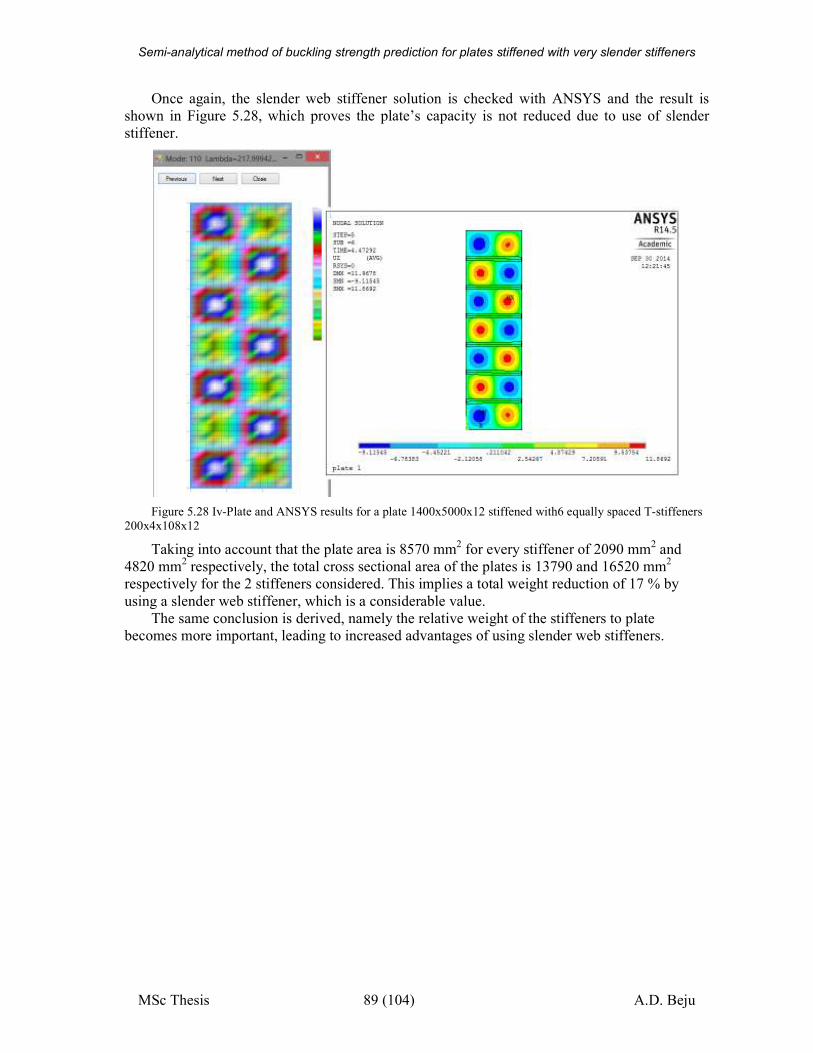
Semi-analytical method of buckling strength prediction for plates stiffened with very slender stiffeners
MSc Thesis 89 (104) A.D. Beju
Once again, the slender web stiffener solution is checked with ANSYS and the result is
shown in Figure 5.28, which proves the plate’s capacity is not reduced due to use of slender
stiffener.
Figure 5.28 Iv-Plate and ANSYS results for a plate 1400x5000x12 stiffened with6 equally spaced T-stiffeners
200x4x108x12
Taking into account that the plate area is 8570 mm2 for every stiffener of 2090 mm
2 and
4820 mm2 respectively, the total cross sectional area of the plates is 13790 and 16520 mm
2
respectively for the 2 stiffeners considered. This implies a total weight reduction of 17 % by
using a slender web stiffener, which is a considerable value.
The same conclusion is derived, namely the relative weight of the stiffeners to plate
becomes more important, leading to increased advantages of using slender web stiffeners.
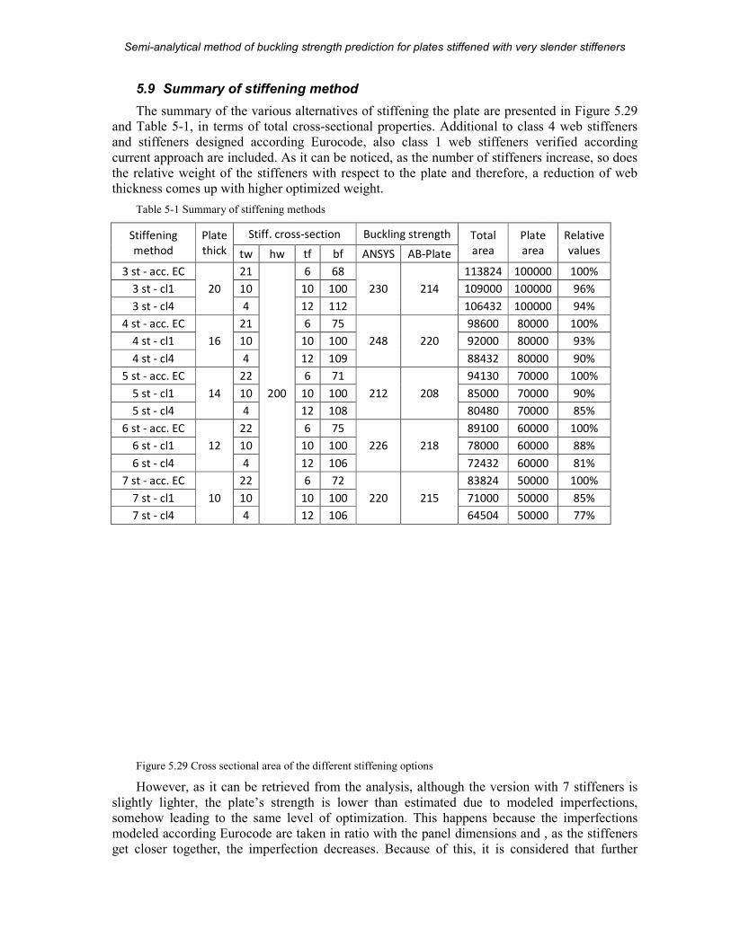
Semi-analytical method of buckling strength prediction
MSc Thesis
5.9 Summary of stiffening method
The summary of the various alternatives
and Table 5-1, in terms of total cross
and stiffeners designed according Eurocode, also class 1 web stiffeners verified according
current approach are included. As it can be noticed, as the number of stiffeners increase, so does
the relative weight of the stiffeners with respect to the plate and therefore, a reduction of web
thickness comes up with higher optimized weight.
Table 5-1 Summary of stiffening methods
Stiffening
method
Plate
thick
Stiff. cross
tw hw
3 st - acc. EC
20
21
200
3 st - cl1 10
3 st - cl4 4
4 st - acc. EC
16
21
4 st - cl1 10
4 st - cl4 4
5 st - acc. EC
14
22
5 st - cl1 10
5 st - cl4 4
6 st - acc. EC
12
22
6 st - cl1 10
6 st - cl4 4
7 st - acc. EC
10
22
7 st - cl1 10
7 st - cl4 4
Figure 5.29 Cross sectional area of the different stiffening options
However, as it can be retrieved from the analysis, although the version with
slightly lighter, the plate’s strength
somehow leading to the same level of optimization.
modeled according Eurocode are taken in ratio with the panel dimensions and , as the stiffen
get closer together, the imperfection decreases.
analytical method of buckling strength prediction for plates stiffened with very slender stiffeners
90 (104)
Summary of stiffening method
various alternatives of stiffening the plate are presented in
, in terms of total cross-sectional properties. Additional to class 4 web stiffeners
and stiffeners designed according Eurocode, also class 1 web stiffeners verified according
As it can be noticed, as the number of stiffeners increase, so does
ight of the stiffeners with respect to the plate and therefore, a reduction of web
thickness comes up with higher optimized weight.
Summary of stiffening methods
cross-section Buckling strength Total
area
Plate
area tf bf ANSYS AB-Plate
6 68
230 214
113824 100000
10 100 109000 100000
12 112 106432 100000
6 75
248 220
98600 80000
10 100 92000 80000
12 109 88432 80000
6 71
212 208
94130 70000
10 100 85000 70000
12 108 80480 70000
6 75
226 218
89100 60000
10 100 78000 60000
12 106 72432 60000
6 72
220 215
83824 50000
10 100 71000 50000
12 106 64504 50000
Cross sectional area of the different stiffening options
However, as it can be retrieved from the analysis, although the version with
he plate’s strength is lower than estimated due to modeled imperfections
somehow leading to the same level of optimization. This happens because the imperfections
modeled according Eurocode are taken in ratio with the panel dimensions and , as the stiffen
get closer together, the imperfection decreases. Because of this, it is considered that
plates stiffened with very slender stiffeners
A.D. Beju
of stiffening the plate are presented in Figure 5.29
Additional to class 4 web stiffeners
and stiffeners designed according Eurocode, also class 1 web stiffeners verified according
As it can be noticed, as the number of stiffeners increase, so does
ight of the stiffeners with respect to the plate and therefore, a reduction of web
Plate
Relative
values
100000 100%
100000 96%
100000 94%
80000 100%
80000 93%
80000 90%
70000 100%
70000 90%
000 85%
60000 100%
60000 88%
60000 81%
50000 100%
50000 85%
50000 77%
However, as it can be retrieved from the analysis, although the version with 7 stiffeners is
estimated due to modeled imperfections,
This happens because the imperfections
modeled according Eurocode are taken in ratio with the panel dimensions and , as the stiffeners
it is considered that further
Semi-analytical method of buckling strength prediction
MSc Thesis
increase of the number of stiffeners will not have a benefic effect over the weight of the entire
plate. This however is a very sensitive conclusion, in cu
optimization level might be obtained which however requires advanced imperfection analysis
and is not considered here.
By plotting the relative own weight for each plate thickness
stiffeners can be even better observed. It is shown the benefits of using a class 4 web stiffener can reach up to
respect to a stiffener designed by means of Eurocode and up to 9%
stiffener.
Figure 5.30 Relative own-weight reduction of plates using 3 different stiffener approaches
These results however give an indication of the amount of material that can be certain plate with a certain stiffener arrangement by using different design rules for the
stiffeners. A generalized results overview is given in chapter
analytical method of buckling strength prediction for plates stiffened with very slender stiffeners
91 (104)
increase of the number of stiffeners will not have a benefic effect over the weight of the entire
This however is a very sensitive conclusion, in current case taken conservatively. Further
optimization level might be obtained which however requires advanced imperfection analysis
By plotting the relative own weight for each plate thickness, the usability of slender
s can be even better observed. It is shown in that, for closely spaced together stiffeners, the benefits of using a class 4 web stiffener can reach up to 23% in terms of saved weight
respect to a stiffener designed by means of Eurocode and up to 9% with respect to a class 1
weight reduction of plates using 3 different stiffener approaches
an indication of the amount of material that can be certain plate with a certain stiffener arrangement by using different design rules for the
stiffeners. A generalized results overview is given in chapter 6.
plates stiffened with very slender stiffeners
A.D. Beju
increase of the number of stiffeners will not have a benefic effect over the weight of the entire
rrent case taken conservatively. Further
optimization level might be obtained which however requires advanced imperfection analysis
, the usability of slender
, for closely spaced together stiffeners, % in terms of saved weight with
th respect to a class 1
an indication of the amount of material that can be saved for a certain plate with a certain stiffener arrangement by using different design rules for the
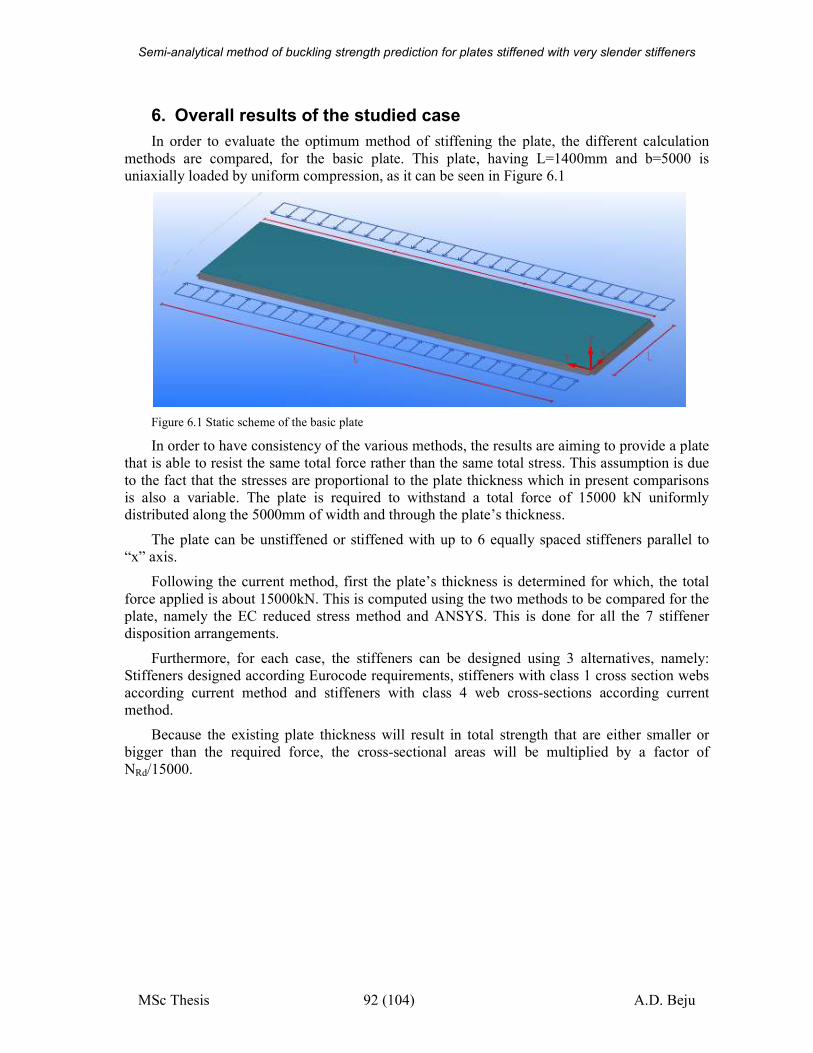
Semi-analytical method of buckling strength prediction for plates stiffened with very slender stiffeners
MSc Thesis 92 (104) A.D. Beju
6. Overall results of the studied case
In order to evaluate the optimum method of stiffening the plate, the different calculation
methods are compared, for the basic plate. This plate, having L=1400mm and b=5000 is
uniaxially loaded by uniform compression, as it can be seen in Figure 6.1
Figure 6.1 Static scheme of the basic plate
In order to have consistency of the various methods, the results are aiming to provide a plate
that is able to resist the same total force rather than the same total stress. This assumption is due
to the fact that the stresses are proportional to the plate thickness which in present comparisons
is also a variable. The plate is required to withstand a total force of 15000 kN uniformly distributed along the 5000mm of width and through the plate’s thickness.
The plate can be unstiffened or stiffened with up to 6 equally spaced stiffeners parallel to
“x” axis.
Following the current method, first the plate’s thickness is determined for which, the total
force applied is about 15000kN. This is computed using the two methods to be compared for the
plate, namely the EC reduced stress method and ANSYS. This is done for all the 7 stiffener
disposition arrangements.
Furthermore, for each case, the stiffeners can be designed using 3 alternatives, namely:
Stiffeners designed according Eurocode requirements, stiffeners with class 1 cross section webs
according current method and stiffeners with class 4 web cross-sections according current
method.
Because the existing plate thickness will result in total strength that are either smaller or
bigger than the required force, the cross-sectional areas will be multiplied by a factor of
NRd/15000.

Semi-analytical method of buckling strength prediction
MSc Thesis
Figure 6.2 Total cross sectional area of diff
analytical method of buckling strength prediction for plates stiffened with very slender stiffeners
93 (104)
Total cross sectional area of different stiffening solutions
plates stiffened with very slender stiffeners
A.D. Beju
erent stiffening solutions

Semi-analytical method of buckling strength prediction
MSc Thesis
As it can be observed in Figure
by stiffening the plate. This however happened until a certain extent, in current case being 4
stiffeners equally distributed across the plate’s width.
stiffeners and decrease in plate thickness, although it results in an improved buckling stress at
failure, the total applied load decreases.
For the case of 4 stiffeners per platto the most conservative but fastest to analyze case, of plate check according the Eurocode with
stiffeners designed according Eurocode rules. The results are shown in
Figure 6.3 Relative material saving for a plate stiffened with 4 stiffeners
It can be noticed that by designing the stiffeners according to current method, up to 7% of
material can be saved for class 1 web stiffeners and up to 11% for class 4 web stiffeners, in the
stiffeners own weight. Furthermore, up to 15% of material can be gained in plate thickness by
analyzing it in ANSYS with respect to a quick Eurocode check. All
saving can add up to 25 % in the end, representing a major gain.
However, the results are sensitive to a multitude of factors and can differ from case to case,
but it can be concluded that an ANSYS analysis is worth doing in order to optimize the plate
thickness, while the option of slender web stiffeners is worth considering when the stiffener’s
weight becomes considerable relative to plate’s weight.
analytical method of buckling strength prediction for plates stiffened with very slender stiffeners
94 (104)
Figure 6.2 the required total strength can be achieved more efficient
by stiffening the plate. This however happened until a certain extent, in current case being 4
ually distributed across the plate’s width. Further increase in the number of
stiffeners and decrease in plate thickness, although it results in an improved buckling stress at
failure, the total applied load decreases.
For the case of 4 stiffeners per plate 6, the relative material saving is estimated with respect to the most conservative but fastest to analyze case, of plate check according the Eurocode with
stiffeners designed according Eurocode rules. The results are shown in Figure 6.
Relative material saving for a plate stiffened with 4 stiffeners
It can be noticed that by designing the stiffeners according to current method, up to 7% of
ass 1 web stiffeners and up to 11% for class 4 web stiffeners, in the
stiffeners own weight. Furthermore, up to 15% of material can be gained in plate thickness by
analyzing it in ANSYS with respect to a quick Eurocode check. All-in-all the total material
saving can add up to 25 % in the end, representing a major gain.
However, the results are sensitive to a multitude of factors and can differ from case to case,
but it can be concluded that an ANSYS analysis is worth doing in order to optimize the plate
ickness, while the option of slender web stiffeners is worth considering when the stiffener’s
weight becomes considerable relative to plate’s weight.
plates stiffened with very slender stiffeners
A.D. Beju
the required total strength can be achieved more efficient
by stiffening the plate. This however happened until a certain extent, in current case being 4
Further increase in the number of
stiffeners and decrease in plate thickness, although it results in an improved buckling stress at
e 6, the relative material saving is estimated with respect to the most conservative but fastest to analyze case, of plate check according the Eurocode with
.3.
It can be noticed that by designing the stiffeners according to current method, up to 7% of
ass 1 web stiffeners and up to 11% for class 4 web stiffeners, in the
stiffeners own weight. Furthermore, up to 15% of material can be gained in plate thickness by
all the total material
However, the results are sensitive to a multitude of factors and can differ from case to case,
but it can be concluded that an ANSYS analysis is worth doing in order to optimize the plate
ickness, while the option of slender web stiffeners is worth considering when the stiffener’s
Semi-analytical method of buckling strength prediction for plates stiffened with very slender stiffeners
MSc Thesis 95 (104) A.D. Beju
7. Summary and design considerations
7.1 Main goals
The current work presents a complex method analyzing the buckling capacity of stiffened
and unstiffened plates in structures where their own weight is critical. Three main aspects were
involved, which are summarized here.
Firstly, a design tool for analyzing these plates has been developed which both analyze
plate’s behavior and provides the necessary output data for an optimized design. The tool is
based on a semi-analytical method, by assuming a certain deformed shape of the structure and
then determining it from the equilibrium of internal and external forces through the principle of
stationary potential energy. The tool is designed for specific types of plates, its use being limited
to those plates that satisfy the assumptions in 7.2. The main advantage of developing such a tool
is that the assumptions are implemented automatically in the calculations and therefore it is easy
to use. It also proves to be faster than non-linear finite element analyses, which also require
experienced users.
Furthermore, the method is compared with the results obtained through a non-linear finite
element analysis using ANSYS, as well as with the current design practice, namely Eurocode.
The results of the current method are found to be close to the ANSYS analysis and therefore, the
tool is able to estimate the amount of conservativeness of the Eurocode. However, note must be
taken that the tool is intended to be a design tool, its approximation errors being both positive
and negative. In this way, the engineer is able to compare the advantage of strength gained by
doing a non-linear finite element analysis with the disadvantage of the time spent in performing
such a tedious task, and decide rather a quick Eurocode check is accurate enough or significant
level of optimization can be achieved through FEM.
Finally, the conservatism of the Eurocode is exploited not just in the plate capacity but also
in the stiffeners. Current Eurocode verifications lead to stocky stiffeners for which, in densely
stiffened structures, their own weight has a bigger influence over the total weight of the
structure. These stiffeners are designed to reach yield before buckling, which is not the case of
the plate itself and therefore it is sufficient to design the stiffeners to resist the failure load only.
In order to reduce their weight while still maintain the same stiffness, their web thickness is decreased and the dimensions of the flange adjusted accordingly.
7.2 Assumptions
The main assumptions considered are presented in the beginning of chapters 3 and 4.
The plate, which is a part of a bigger structure, such as box girders, is considered to be
supported out of plane along its all four edges. This is due to high relative stiffness at the
location of the bulkheads for example.
However, the plate is free to move in-plane, but its edges are forced to remain straight, due
to the fact that it is connected to the adjacent plates.
Because of this assumptions, when the plate deforms out of plane under compression, its
buckling limit is most likely reached due to yielding at the panel’s corners, as it can be seen in
Figure 3.2.
One of the most important issues in analyzing the buckling strength is the initial shape
considered as imperfections, as well as it’s amplitude. Current method uses the critical buckling
shape of the perfect plate, scaled to the specified imperfections, which, by default are taken
according to the Eurocode. Further detailing of this aspect can be found in chapter 7.4.1.
Semi-analytical method of buckling strength prediction for plates stiffened with very slender stiffeners
MSc Thesis 96 (104) A.D. Beju
For the stiffened plates, the main assumption of the method, on which also the design tool is
based, is that the plate’s capacity will always be reached due to local buckling of the plate.
Therefore, in the analysis of the plate, the stiffener is considered to have sufficient strength,
stability and stiffness for the plate to behave in this way. Once these values are known, an
equivalent stiffener capable of satisfying these assumptions is designed.
The stiffener is considered snipped. This assumption implies that the stiffener is terminated
shortly before the end of the plate and therefore, the load is applied to the plate only. Since this
is not commonly used in current projects, where the stiffener is continuous and therefore taking
also initial load, this assumption is further detailed in chapter 7.5.
Another important assumption regarding the stiffeners is that, due to the fact that their web
is very slender and thus having low torsional rigidity, the internal energy due to their torsional
stiffness is neglected in current method. Therefore, the method gives conservative results when
thicker web stiffeners are used, as it can be seen in Figure 4.16 and Figure 4.17. Furthermore,
this aspect is presented in detail in Chapter 7.4.2.
All the analyses are performed on a material yield strength of 345MPa, as the one specified
in the two projects used.
7.3 Summary of the method
In chapter 4.8 the workflow of the design tool is presented. The main steps of current
method can be summarized as:
• Input of geometry and loading conditions
• Performing an elastic analysis and determine the critical buckling stress as well as the critical buckling shape
o Scale the critical buckling shape to the required imperfections
o Determine the necessary stiffness the stiffener must have such that the plate fails
in local buckling, iteratively
• Perform a buckling strength analysis under a rate form, namely determine the relation between the increase in loads and the increase in deformations at a certain stage
o Set a pseudo-time for the analysis, namely the size of the steps taken in the
analysis
o In an iterative way, at each step, calculate the stiffness matrix from the principle
of stationary potential energy in order to satisfy equilibrium.
o Increase the load factor and amplitudes accordingly, and proportional to the step
size
o Check the plate’s to see rather the strength criterion has been met. If yes, the buckling strength has been determined, otherwise continue with the iteration.
• Extract the results at failure (distribution of stresses, displacements)
• Perform a buckling check of the plate according Eurocode’s reduced stress method in order to
compare the results.
• Design an equivalent stiffener having the assumed stiffness and height that is able to satisfy the Eurocode check for the failure state.
• Design an equivalent slender web stiffener that satisfies the checks presented in chapter 5.
Semi-analytical method of buckling strength prediction for plates stiffened with very slender stiffeners
MSc Thesis 97 (104) A.D. Beju
7.4 Sensitive design aspects
Since the method is dealing with thin plates of which behavior is very sensitive to a lot of
factors, careful estimation of the influence of this factors should be accounted for. The most
important are presented below.
7.4.1 Imperfection shape
The imperfection shape that is taken into account in estimating the buckling strength of a
plate becomes very important, especially for thin plates where their values are relatively high to the thickness of the plate.
For these cases, the maximum amplitude of the shape leads to significant second order
effects, thus exponentially decreasing the plate`s capacity.
In the current method, the plate is considered to have an imperfection shape equivalent to
the critical buckling mode, since most of the times the imperfections are caused due to stresses
in the initially perfect plate, during manufacturing. However, in some cases, the first several
critical buckling modes can be very close to each other, as it is also shown in Figure 3.28and
Figure 3.29. In such cases, an imperfection shape according to a higher mode use for the analysis
might result in lower capacity than if the critical mode would be used. In such cases, detailed
investigation should be performed and plate reanalyzed with those imperfection shapes, taking the minimum value as the plate’s strength.
In the current work, the imperfection considered has the shape of the critical mode of the
structure, thus with stiffeners already attached, and scaled up to the minimum dimension of the
biggest panel, divided by 200, as specified in Annex C of the EN1993-1-5.
For the stiffeners, the global imperfection along their length is taken into account in
calculating the stresses to which they are subjected, by adding it to the eccentricity of the cross-
section. The imperfections of the web are already considered in its verification, which is done
according to the Reduced stress method of the Eurocode.
7.4.2 Lateral torsional stability
Because the web of the stiffener is very thin in comparison to the thickness of the plate, its
torsional stiffness is insignificant, which is the main reason of neglecting it in the current
method. Therefore the stiffener’s connection to the plate acts like a piano hinge with the stiffener
changing the sign of its rotation with respect to the plate, as it is also shown in Figure 5.11.
Because the of the piano hinge connection, the stiffener need to be stabilized with additional
plates perpendicular to its web and the plate, at its end, as it is shown in .
Due to the position of the stabilizers – close to out of plate supports – and the piano hinge
behavior, as well as the significant warping stiffness of the top flange, in absolute terms, the
stiffener will maintain its initial position, while the plate is rotated due to out of plane
displacements. This behavior is shown in Figure 5.8.
7.4.3 Fatigue and residual stresses
The residual stresses can significantly decrease the capacity of the plate. Some of them are
already taken into consideration through imperfections. However, the stresses due to welding of
the web to the plate, flange and stabilizers are prone to cause severe deformations in the thin
web. Furthermore, at these locations, fatigue becomes very important, taking into account the
type of structures the plates are designed for, like cranes. However, this aspect is outside the
scope of current work and detailed investigation is necessary.
Semi-analytical method of buckling strength prediction for plates stiffened with very slender stiffeners
MSc Thesis 98 (104) A.D. Beju
7.5 Applicability of the method in current practice
The current design method is meant to be use in analysis of plates in structures such as the
ones presented in Figure 1.1and Figure 1.2. These structures consists of box girders stiffened
inside both along their flanges and webs, in order to improve the stability of the plates with a
reduced own weight. The weight reduction is critical since, even if the manufacturing costs are
increased, the performance of the structure is also increased, the optimized own weight being
converted in lifting capacity. The former costs are one-time only while the gain due to increased capacity brings a much higher life-time income. The use of current method and its assumptions
are presented below, thus linking the theoretical aspect with the reality.
7.5.1 Web plates
The plates used in the webs of the box girders are subjected to biaxial stresses as well as
shear. So far, in the design tool, the method has been implemented to analyze plate subjected to
constant stresses. Since the bending will generate a linear compressive stress, the design tool’s
results will have a higher error with respect to a non-linear analysis.
However, a conservative assumption might be made by the engineer, considering the plate
constantly loaded across the width with a stress equal to the highest value of the stress.
The method itself, on the other hand, is able to analyze any distribution of loading, thus also the tool can be upgraded to implement this feature. In order to do this, analytical evaluation of
the expressions of the energies presented in Chapter 3.3.5 and 4.5.3 are necessary.
7.5.2 Flange plates
The tool is currently more suitable for the flange plates, which are subjected to uniform
compression. Their interior bulkheads provide out of plane stiffness that is several orders of
magnitude higher than the one of the plate, thus they can be considered as supports.
However one major remark is that it is very common to have openings in the bulkheads and
therefore the stiffeners passing through. Because of this continuity, the load that is applied to the
plate is also applied to the stiffener at its ends. This behavior is different from the one assumed
in current paper where it is considered that the stiffener is not loaded at its ends but just by the
redistribution of stresses from the plate. For this reason, careful attention should be taken when
referring to the buckling strength of the plate, which in current design tool is only acting on the
plate.
If continuous (end loaded) stiffeners, are used, the buckling strength of the plate as
calculated by current design tool should be reduced proportional to the loaded areas, such that
the total load on the plate edge remains constant. The buckling strength of a plate loaded with
end stiffeners reads:
NÜÀ,)�À � uêé∗ç�l}¸vç�l}¸v�çh¸.�� � J\\#� �7-1�In order to prove the conservativeness of this remark, the stresses should be compared to the
assumed case.
Firstly, from the above expression, where NÜÀ is the failure load of the plate in local
buckling, it can be concluded that the plate is able to withstand NÜÀ,)�À which has a lower value,
and therefore this difference in assumptions has effect mainly on the stiffener.
For calculating the stresses in the stiffener, consideration should be taken about the different
position of the loading. The axial stress in the stiffener is NÜÀ,)�À which has the same value as
the one computed in chapter 5.2.2.
Semi-analytical method of buckling strength prediction for plates stiffened with very slender stiffeners
MSc Thesis 99 (104) A.D. Beju
NJ,Ü�À � NJ ∗ �v��∗cçh¸,v����v��∗c �7-2�The influence of having the load introduced also in the stiffeners is positive when
computing the bending moment due to the eccentricity between the plate axis and the composed
cross-section’s neutral axis. This bending moment reads:
�À � N4j-c� ∗ n�ÍÍ ∗ � ∗ ��% +�%� � NÜÀ,)�À ∗ ��% +�%� �7-3�Considering that NÜÀ,)�À is smaller than NJ, also the stresses due to bending moment are
smaller, and therefore it can be safely assumed that the end loaded stiffeners are safely analyzed
with this method.
7.5.3 Lateral stability restraints
Because the web of the stiffener has very low stiffness around its weak axis, the stiffener
needs to be stabilized at the ends.
In practice, in order to avoid the welding of lateral stabilizing plates at the ends of the
stiffeners, and considering the continuous aspect of the stiffeners, the stiffeners can be laterally
stabilized by welding them to the bulkheads.
If for the plate is conservative to assume it simply supported at the location of the bulkheads
even though their rotation is partially restrained by their continuousness, for the stiffeners a
detailed analysis of the bending moments that develop at those locations should be performed.
Special attention should also be paid to the detail of connecting the stiffeners to the
bulkhead since the thin web behavior can be easily influenced by such a detail.
7.5.4 Manufacturing issues
One of the most important aspects in manufacturing these plates is to maintain the
correlation between the assumed imperfections and the ones occurring in reality.
Having to deal with thin plates, the imperfections become significant. However, nowadays,
as the technology progresses the plate manufacturing process can be combined with the welding
procedure in the case of parallel stiffeners. By doing so, the stiffeners are welded to the plate
immediately after the plate reaches the required thickness in the manufacturing process. As a
consequence, the residual stresses due to manufacturing and welding will generate imperfections
on the already stiffened panel, which is also the assumption of current work. In future works, the
current tool can be improved to take into account also any kind of imperfection shape. As the
method is intended for easy use and not to recreate a FE software, this is not implemented at this
stage.
Semi-analytical method of buckling strength prediction for plates stiffened with very slender stiffeners
MSc Thesis 100 (104) A.D. Beju
8. Conclusions and recommendations
8.1 Conclusions
The conclusions of the main goals presented in chapter 7.1 are considered to be achieved,
being presented below.
8.1.1 Alternative method of estimating the buckling behavior of plates
The method presented in current work has been proven to give results close to the ones
obtained by non-linear finite analysis, by using the failure criteria presented in chapter 4.5.2.
However, in some cases of stiffened plates, the method still provided conservative results due to
the high amount of post-buckling reserve strength the plate exhibits. This gap can be decreased by considering alternative failure criteria.
Testing the method through a high variety of plates and stiffener arrangements has been
observed that the shape of the imperfection is very important. The governing buckling strength is
often obtained by taking the critical buckling mode scaled to required imperfection. However,
when the first modes’ elastic buckling stresses are close to each other, the imperfections of the
second mode might become governing. For these cases, the analysis should also be performed by
using second or even 3rd
buckling mode as imperfection shape and the minimum value obtained
for strength taken as the buckling strength of the plate.
The current method uses a number of degrees of freedom that is 2-3 orders of magnitude
smaller than a finite element model. This makes the design tool very efficient from computational time point of view, allowing a quick estimation of the buckling strength of a
plate.
The design tool consists also of plate verification according to Eurocode, being able to
provide a detailed calculation of it, as well as detailed overview of the two methods. Because the
scope of current work involved the method and its results and because intensive computer
programming skills are required, the tool has not been extensively programmed from graphical
point of view, the results being extracted and processed through external software such as Excel.
All these improvements and functionalities can be implemented in the program’s menu for the
easiness of use by any engineer. They include, but are not limited to, eurocode detailed checks
with intermediate values, estimation of the weight optimization level that can be gained by performing non-linear finite element analyses and even statistics about similar plates results
previously analyzed.
8.1.2 Conservativeness amount of current design practice (Eurocode)
It has been observed that for unstiffened plate having high slenderness, the amount of
material that can be saved by doing a detailed non-linear FE analysis can go up to 40-50%,
therefore it is worth investigating in detail the behavior of the plate through FEM.
Such slender plates are needed in the areas where the applied stress at the ends is relatively
low with respect to material’s yield strength, but where continuity is needed, such as parts of
webs of flanges in stiffened box girders. A possible reason for these high discrepancies is the
increased amount of post-buckling reserve strength such plates is known to have.
On the other hand, for stockier plates, the Eurocode predictions’ level of conservativeness is
low with respect to detailed non-linear FE analysis. This is a consequence of the fact that the
imperfections have a smaller influence over the plate’s buckling behavior.
Semi-analytical method of buckling strength prediction for plates stiffened with very slender stiffeners
MSc Thesis 101 (104) A.D. Beju
8.1.3 Optimization of the weight reduction by using very slender web stiffeners
The weight of the plates can be further reduced by reducing the thickness of the stiffeners’
webs. In the Eurocode a set of rules for checking the stiffeners of stiffened plates are presented,
which lead to very stocky stiffeners. An alternative method is presented in current work and
tested using finite element non-linear analysis. The results are found to be consistent, proving it
is worthwhile taking the method one step further and test it on real specimens.
Designing the stiffener by the ways of current method consists of two main steps: design a
basic stiffener having a certain required stiffness and optimize it by reducing its web thickness.
The scope of the stiffeners is to provide stiffness to the plate, namely forcing the plate to
buckle in a local mode. It has been noted that above a certain value of stiffness for the stiffener,
the plate will buckle in local mode, with the same critical stress, regardless of the further
increase of the stiffener’s stiffness. Since this threshold value is not taking into account the
imperfections, a minimum required stiffness can be set as the double of this value. A stiffener is
designed to meet this requirement, the so called basic stiffener, which is used in calculating the
failure load of the plate.
Once the failure load is known, an equivalent stiffener is designed, by decreasing the web thickness and increasing the flange, such that it has the same stiffness but smaller cross sectional
area. This stiffener should have sufficient strength and stability to resist the failure load of the
plate.
In such stiffeners, the critical part will obviously be the web, which should be able to
transfer the stresses across the stiffener’s height, thus activating the flange. Therefore, the
stiffener should be verified as a bi-axially loaded plate, in longitudinal direction with the
redistributed stresses from the plate while in transversal directions with the stresses generated by
the bending due to eccentricity of the load. This assumption is valid taking into account that the
stiffness of the web perpendicular to its plane is insignificant with respect to the stiffness of the
surrounding plates (flange, plate, stabilizers). In order to do this, the conservative method of the Eurocode is used, as presented in chapter 10 of EN1995-1-5, namely reduced stress method.
The current assumptions have been verified using ANSYS and they were found to be
reasonable. Several plates and stiffeners arrangements have been compared, with both stiffeners
designed according Eurocode and current method. I was found that the current method comes
with important weight reduction amounts, especially for dense stiffened plates, of which own
weight can be decreased with up to 15%.
It is therefore concluded that, by increasing the number of stiffeners on a plate, significant
own weight reduction can be achieved and even further maximized by using slender web
stiffeners. This is due to the fact that, as the panels’ dimensions in-between the stiffeners become
smaller, the imperfections decrease and thus the plate thickness can be decreased. This also results in an increase in the stiffener to plate weight ratio, which makes the current method even
more effective. On the other hand, the careful attention must be paid in order not to
underestimate the magnitude of imperfections which are critical in determining the plate’s
failure stress.
However, the method improves the buckling behavior of the plate and it is evaluated in
terms of stresses, which are dependent on the plate thickness itself. Being a part of a structure,
the plate is in fact subjected to a total force, distributed to its cross-section and therefore, as the
thickness decreases, the applied stress increases. Special attention must be paid by the engineer
in evaluating the stress to which the plate is subjected.
Semi-analytical method of buckling strength prediction for plates stiffened with very slender stiffeners
MSc Thesis 102 (104) A.D. Beju
8.2 Applicability and recommendations
The current method provides a fast evaluation of a stiffened plate being able to estimate the
amount of conservativeness a Eurocode check has with respect to a non-linear finite element
analysis. It is also able to further maximize the weight reduction by designing a slender web
stiffener that has little or no influence on the plate’s behavior with respect to a stiffener designed
by means of Eurocode.
The method is specifically adapted for parts of box girders such as the ones presented in the two projects linked to current work. However, in the transition between the theoretical aspects
taken into account and the real-life issues, several aspects should be carefully taken into account.
Firstly, in these box girders the stiffeners are continuous over the length of the girder while
in present work they are assumed to be interrupted. This issue is detailed in chapter 7.5.2 and has
been found that the assumption is on the conservative side.
Secondly, due to low out of plane stiffness of the web, lateral stabilizers are needed to
prevent the flip-over of the stiffener. Considering previous remark, these can be achieved by
directly connecting the stiffeners to the bulkhead inside the box girders.
Further solutions of increasing the web stability can be found, one of them is by using stiff
foams on web’s sides. This will increase web’s stability with a negligible increase of weight. This however comes with additional costs which should be also taken into account.
Last but not least, special attention must be paid to the magnitude of imperfections. These
are highly dependent on the manufacturing process and handling.
8.3 Future work
The method has been optimized and implemented for plates with parallel stiffeners loaded
by constant compression stresses. Its implementation for randomly loaded plates as well as
complex shapes can be considered in the future development of the tool.
Several aspects of the behavior of such stiffeners should also be investigated in detail and
tested in the laboratory since they were only briefly accounted for in the present work. They
include, but are not limited to, fatigue, residual stresses, and imperfections.
8.4 General conclusion
Considering the above, through current work it can be concluded that the amount of
conservativeness in the Eurocode leads to an increased weight reduction that can be obtained by
using finite element non-linear analysis, up to 10-15%. Furthermore, the use of slender webs for
stiffeners is a viable solution of decreasing even more the own weight of the structure where this
is critical. For slender plates, where an increased amount of stiffener is needed in order to
increase the plate’s stability, up to 5% of material can be saved with respect to using a class 1
web stiffener and up to 11% with respect to using a stiffener designed by the means of Eurocode.
These would lead to a total weight optimization of up to 20-25% when using a slender web
stiffener on a non-linear FE analysis with respect to a quick Eurocode check of the plate with
stiffeners that meet the Eurocode checkings.
However, additional costs are involved in the manufacturing of such plates, which should be
further estimated in collaboration with manufacturers. Due to their use in lifting equipment,
where the saved weight is converted in lifting capacity, these costs will be suppressed by the
profit generated by improved performance.

Semi-analytical method of buckling strength prediction for plates stiffened with very slender stiffeners
MSc Thesis 103 (104) A.D. Beju
9. References
[1] EN 1993-1-5. Eurocode 3: Design of steel structures. Part 1.5: Plated structural elements.
Brussels: CEN, European Committee for Standardisation; 2005. [2] Brubak L. Semi-analytical buckling strength analysis of plates with constant or varying
thickness and arbitrarily oriented stiffeners. Research report in mechanics, No. 05-6. Norway:
Mechanics Division, Dept. of Mathematics, University of Oslo; 2005. 65 pp.
[3] Brubak L, Hellelsand J, Steen E. Semi-analytical buckling strength analysis of with
arbitrary stiffener arrangements. Journal of Constructional Steel Research 2007;63(4):532–43.
[4] Brubak L, Hellelsand J. Approximate buckling strength analysis of arbitrarily stiffened,
stepped plates. Eng Struct 2007;29(9):2321–33.
[5] Brubak L, Hellelsand J. Semi-analytical postbuckling and strength analysis of
arbitrarily stiffened plates in local and global bending. Thin- Walled Structures 2007;45(6):620–
33.
[6] Brubak L, Hellelsand J. Strength criteria in semi-analytical, large deflection analysis of stiffened plates in local and global bending. Thin-Walled Structures 2008;46(12):1382–90.
[7] Brubak L, Hellelsand J. Semi-analytical postbuckling analysis of stiffened imperfect
plates with a free or stiffened edge. Computers and Structures 2011;89(17–18):1574–85.
[8] Brubak L, Andersen H, Hellelsand J. Ultimate strength prediction by semi-analytical
analysis of stiffened plates with various boundary conditions. Thin-Walled Structures 2013;
62:28-36
[9] Van Ham A. Interaction between plate and column buckling, M.Sc. Thesis, Faculty of
Civil Engineering and Geosciences, Department of Structural Engineering, Delft University of
Technology, The Netherlands, 2012
[10] Marguerre K. Zur theorie der gekr¨ummten platte grosser form¨anderung. In:
Proceedings of the 5th international congress for applied mechanics. 1938. p. 93–101. [11] Levy S. Bending of rectangular plates with large deflections. Report 737.NACA. 1942.
[12] Byklum E, Amdahl J. A simplified method for elastic large deflection analysis of plates
and stiffened panels due to local buckling. Thin-Walled Structures 2000;40(11):925–53.
[13] Byklum E. Ultimate strength analysis of stiffened steel and aluminium panels using
semi-analytical methods. Dr. Ing. Thesis, Norwegian University of Science and Technology,
Trondheim,Norway; 2002.
[14] Johansson B. et al. Commentary and worked examples to EN 1993-1-5 “Plated
structural Elements”. First edition (2007)
[15] Beg D. Plate and box girder stiffener design in view of Eurocode 3 part 1.5, Ljubljana,
Slovenia, 2008 [16] Narayanan R. et al. Beams subjected to torsion and bending I, Institute for Steel
Development & Growth (INSDAG)
[17] Bakker M et al., Post-buckling stress of uniformly compressed plates, Lisbon, Portugal
2006
[18] Bakker M et al., Prediction of the elasto-plastic post-buckling strength of uniformly
compressed plates from the fictitious elastic strain at failure Thin-Walled Structures 2009;47(1-
13)
[19] ANSYS Inc., ANSYS Documentation 11.0, Southpointe, Canonsburg, PA, 2007

Semi-analytical method of buckling strength prediction for plates stiffened with very slender stiffeners
MSc Thesis 104 (104) A.D. Beju
Annex 1A – ANSYS command file for an unstiffened plate
finish
/CLEAR
/CWD,'E:\Academic\Netherlands\Dizertatie\ans
ys\Plate commands'
ABBRES,NEW,'123',' ',' '
/title, plate 1
/prep7
t=12
sigmax=100
sigmay=0
sysxratio=0
dstep=1
dmax=10
fyd=345/1.1
Eyoung=210000
l=1400
b=5000
wspec=min(l,b)/200
ET,1,SHELL281
MP,EX,1,Eyoung
MP,PRXY,1,0.3
K,1,0,0,0
K,2,l,0,0
K,3,l,b,0
K,4,0,b,0
L,1,2
L,2,3
L,3,4
L,4,1
AL,1,2,3,4
R,1,t,t,t,t, , ,
ASEL,S,LOC,Z,0
AATT,1,1,1
ASEL,ALL
SMRTSIZE,1
AMESH, ALL
EPLOT
/ESHAPE,1
!boundary conditions x=L
NSEL,S,LOC,X,l
NSEL,R,LOC,Z,0
D,ALL,UX,0
D,ALL,UZ,0
!boundary conditions x=0
NSEL,S,LOC,X,0
NSEL,R,LOC,Z,0
D,ALL,UZ,0
CP,2,UX,ALL
NSEL,R,LOC,Y,b
F,ALL,FX,sigmax*t*b
F,ALL,FY,-sysxratio*t*L
!boundary conditions y=0
NSEL,S,LOC,Y,0
NSEL,R,LOC,Z,0
D,ALL,UZ,0
D,ALL,UY,0
!boundary conditions y=b
NSEL,S,LOC,Y,b
NSEL,R,LOC,Z,0
D,ALL,UZ,0
CP,4,UY,ALL
ALLSEL
FINISH
!static analysis
/SOLU
outres,all,all
outpr,all,all
ANTYPE,0
PSTRES,ON
SOLVE
finish
!Elastic buckling analysis
/solu
ANTYPE,1
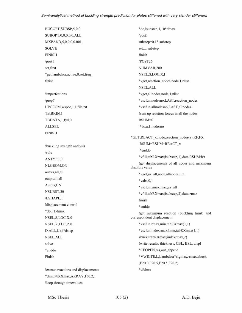
Semi-analytical method of buckling strength prediction for plates stiffened with very slender stiffeners
MSc Thesis 105 (2) A.D. Beju
BUCOPT,SUBSP,5,0,0
SUBOPT,0,0,0,0,0,ALL
MXPAND,5,0,0,0,0.001,
SOLVE
FINISH
/post1
set,first
*get,lambdacr,active,0,set,freq
finish
!imperfections
/prep7
UPGEOM,wspec,1,1,file,rst
TB,BKIN,1
TBDATA,1,fyd,0
ALLSEL
FINISH
!buckling strength analysis
/solu
ANTYPE,0
NLGEOM,ON
outres,all,all
outpr,all,all
Autots,ON
NSUBST,30
/ESHAPE,1
!displacement control
*do,i,1,dmax
NSEL,S,LOC,X,0
NSEL,R,LOC,Z,0
D,ALL,Ux,i*dstep
NSEL,ALL
solve
*enddo
Finish
!extract reactions and displacements
*dim,tabRXmax,ARRAY,150,2,1
!loop through timevalues
*do,isubstep,1,10*dmax
/post1
substep=0.1*isubstep
set,,,,,substep
finish
/POST26
NUMVAR,200
NSEL,S,LOC,X,l
*vget,reaction_nodes,node,1,nlist
NSEL,ALL
*vget,allnodes,node,1,nlist
*vscfun,nodesno,LAST,reaction_nodes
*vscfun,allnodesno,LAST,allnodes
!sum up reaction forces in all the nodes
RSUM=0
*do,a,1,nodesno
*GET,REACT_x,node,reaction_nodes(a),RF,FX
RSUM=RSUM+REACT_x
*enddo
*vfill,tabRXmax(isubstep,1),data,RSUM/b/t
!get displacements of all nodes and maximum
absolute value
*vget,uz_all,node,allnodes,u,z
*vabs,0,1
*vscfun,zmax,max,uz_all
*vfill,tabRXmax(isubstep,2),data,zmax
finish
*enddo
!get maximum reaction (buckling limit) and
correspondent displacement
*vscfun,rmax,min,tabRXmax(1,1)
*vscfun,indexrmax,lmin,tabRXmax(1,1)
zbuck=tabRXmax(indexrmax,2)
!write results. thickness, CBL, BSL, displ
*CFOPEN,res,out,,append
*VWRITE,L,Lambdacr*sigmax,-rmax,zbuck
(F20.0,F20.5,F20.5,F20.2)
*cfclose
Semi-analytical method of buckling strength prediction for plates stiffened with very slender stiffeners
MSc Thesis 106 (1) A.D. Beju
Annex 1B – ANSYS command file for a stiffened plate
finish
/CLEAR
/CWD,'E:\Academic\Netherlands\Dizert
atie\ansys\Plate commands\stiffener'
ABBRES,NEW,'123',' ',' '
/title, plate 1
/prep7
t=16
sigmax=100
sigmay=0
sysxratio=0
dstep=0.2
dmax=10
fyd=345/1.1
Eyoung=210000
l=1400
b=5000
tf=20
tw=20
hw=200+tf/2+t/2
bf=100
x11=0
x12=L
y11=b/4
y12=b/3
x21=0
x22=L
y21=3*b/4
y22=2*b/3
teta1=ATAN((y12-y11)/(x12-x11))
teta2=ATAN((y22-y21)/(x22-x21))
wspec=min(l,b/3)/200
ET,1,SHELL281
MP,EX,1,Eyoung
MP,PRXY,1,0.3
K,1,0,0,0
K,2,l,0,0
K,3,l,b,0
K,4,0,b,0
K,10,x11,y11,0
K,11,x12,y12,0
cutx1=10*cos(teta1)
cuty1=10*sin(teta1)
cutx2=10*cos(teta2)
cuty2=10*sin(teta2)
K,12,x12-cutx1,y12-cuty1,hw
K,13,x11+cutx1,y11+cuty1,hw
K,14,x11+cutx1+bf/2*sin(teta1),y11+cu
ty1-bf/2*cos(teta1),hw
K,15,x12-cutx1+bf/2*sin(teta1),y12-
cuty1-bf/2*cos(teta1),hw
K,16,x12-cutx1-bf/2*sin(teta1),y12-
cuty1+bf/2*cos(teta1),hw
K,17,x11+cutx1-
bf/2*sin(teta1),y11+cuty1+bf/2*cos(teta1),h
w
K,18,x11+10*cos(teta1),y11+10*sin(tet
a1),0
K,19,x12-10*cos(teta1),y12-
10*sin(teta1),0
K,20,x21,y21,0
K,21,x22,y22,0
K,22,x22-cutx2,y22-cuty2,hw
K,23,x21+cutx2,y21+cuty2,hw
K,24,x21+cutx2+bf/2*sin(teta2),y21+cu
ty2-bf/2*cos(teta2),hw
K,25,x22-cutx2+bf/2*sin(teta2),y22-
cuty2-bf/2*cos(teta2),hw
K,26,x22-cutx2-bf/2*sin(teta2),y22-
cuty2+bf/2*cos(teta2),hw
K,27,x21+cutx2-
bf/2*sin(teta2),y21+cuty2+bf/2*cos(teta2),h
w
K,28,x21+10*cos(teta2),y21+10*sin(tet
a2),0
K,29,x22-10*cos(teta2),y22-
10*sin(teta2),0
L,1,2
L,2,11
L,11,21
L,21,3
L,3,4
L,4,20
L,20,10
L,10,1
L,18,19
L,19,12
L,12,13
L,13,18
L,13,14
Semi-analytical method of buckling strength prediction for plates stiffened with very slender stiffeners
MSc Thesis 107 (4) A.D. Beju
L,14,15
L,15,12
L,12,16
L,16,17
L,17,13
L,28,29
L,29,22
L,22,23
L,23,28
L,23,24
L,24,25
L,25,22
L,22,26
L,26,27
L,27,23
!snipped
L,10,18
L,19,11
L,20,28
L,29,21
AL,1,2,30,9,29,8
AL,3,32,19,31,7,29,9,30
AL,4,5,6,31,19,32
AL,9,10,11,12
AL,13,14,15,11
AL,11,16,17,18
AL,19,20,21,22
AL,21,23,24,25
AL,21,26,27,28
R,1,t,t,t,t, , ,
R,2,tw,tw,tw,tw, , ,
R,3,tf,tf,tf,tf, , ,
ASEL,S,LOC,Z,hw/4,hw*3/2
AATT,1,2,1
ASEL,S,LOC,Z,0
AATT,1,1,1
ASEL,S,LOC,Z,hw
AATT,1,3,1
ASEL,ALL
SMRTSIZE,1
AMESH, ALL
EPLOT
/ESHAPE,1
!boundary conditions x=L
NSEL,S,LOC,X,l
NSEL,R,LOC,Z,0
D,ALL,UX,0
D,ALL,UZ,0
!boundary conditions x=0
NSEL,S,LOC,X,0
NSEL,R,LOC,Z,0
D,ALL,UZ,0
CP,2,UX,ALL
NSEL,R,LOC,Y,b
F,ALL,FX,sigmax*t*b
F,ALL,FY,-sysxratio*t*L
!boundary conditions y=0
NSEL,S,LOC,Y,0
NSEL,R,LOC,Z,0
D,ALL,UZ,0
D,ALL,UY,0
!boundary conditions y=b
NSEL,S,LOC,Y,b
NSEL,R,LOC,Z,0
D,ALL,UZ,0
CP,4,UY,ALL
ALLSEL
FINISH
!static analysis
/SOLU
outres,all,all
outpr,all,all
ANTYPE,0
PSTRES,ON
SOLVE
finish
!Elastic buckling analysis
/solu
ANTYPE,1
BUCOPT,SUBSP,5,0,0
SUBOPT,0,0,0,0,0,ALL
MXPAND,5,0,0,0,0.001,
SOLVE
FINISH
/post1
set,first
*get,lambdacr,active,0,set,freq
finish
Semi-analytical method of buckling strength prediction for plates stiffened with very slender stiffeners
MSc Thesis 108 (4) A.D. Beju
!imperfections
/prep7
UPGEOM,wspec,1,1,file,rst
TB,BKIN,1
TBDATA,1,fyd,0
ALLSEL
FINISH
!buckling strength analysis
/solu
ANTYPE,0
NLGEOM,ON
outres,all,all
outpr,all,all
Autots,ON
NSUBST,30
/ESHAPE,1
!displacement control
*do,i,1,dmax/dstep
NSEL,S,LOC,X,0,0.1
D,ALL,Ux,i*dstep
NSEL,ALL
solve
*enddo
Finish
!extract reactions and displacements
*dim,tabRXmax,ARRAY,10*dmax/dst
ep,2,1
!loop through timevalues
*do,isubstep,1,10*dmax/dstep
/post1
substep=0.1*isubstep
set,,,,,substep
finish
/POST26
NUMVAR,200
NSEL,S,LOC,X,l
*vget,reaction_nodes,node,1,nlist
NSEL,ALL
*vget,allnodes,node,1,nlist
*vscfun,nodesno,LAST,reaction_nodes
*vscfun,allnodesno,LAST,allnodes
!sum up reaction forces in all the nodes
RSUM=0
*do,a,1,nodesno
*GET,REACT_x,node,reaction_nodes(a),R
F,FX
RSUM=RSUM+REACT_x
*enddo
*vfill,tabRXmax(isubstep,1),data,RSU
M/b/t
!get displacements of all nodes and
maximum absolute value
*vget,uz_all,node,allnodes,u,z
*vabs,0,1
*vscfun,zmax,max,uz_all
*vfill,tabRXmax(isubstep,2),data,zmax
finish
*enddo
!get maximum reaction (buckling limit)
and correspondent displacement
*vscfun,rmax,min,tabRXmax(1,1)
*vscfun,indexrmax,lmin,tabRXmax(1,1
)
zbuck=tabRXmax(indexrmax,2)
!write results. thickness, CBL, BSL,
displ
*CFOPEN,resarb,out,,append
*VWRITE,L,Lambdacr*sigmax,-
rmax,zbuck
(F20.0,F20.5,F20.5,F20.2)
*cfclose
/prep7
lsel,s,loc,y,y1
lsel,r,loc,z,0
nsll,s,1
*vget,stiffener_nodes,node,,nlist
*vscfun,nodesnostiff,LAST,stiffener_no
des
allsel
finish
/post1
set,,,,,0.1*indexrmax
finish
*dim,stiffnodes,ARRAY,nodesnostiff,3,
1
*do,aa,1,nodesnostiff
/prep7
Semi-analytical method of buckling strength prediction for plates stiffened with very slender stiffeners
MSc Thesis 109 (4) A.D. Beju
*GET,va,node,stiffener_nodes(aa),LOC
,X
*vfill,stiffnodes(aa,1),data,va
*GET,va,node,stiffener_nodes(aa),LOC
,y
*vfill,stiffnodes(aa,2),data,va
finish
/post26
*GET,va,node,stiffener_nodes(aa),U,z
*vfill,stiffnodes(aa,3),data,va
finish
*enddo
*CFOPEN,nodesarbitrar,out!,,append
*VWRITE,stiffnodes(1,1),stiffnodes(1,
2),stiffnodes(1,3),
(F20.5,F20.5,F20.5)
*cfclose
/prep7
lsel,s,loc,y,y1
lsel,r,loc,z,0
nsll,s,1
*vget,stiffener_nodes,node,,nlist
*vscfun,nodesnostiff,LAST,stiffener_no
des
allsel
finish
/post1
set,,,,,0.1*indexrmax
finish
*dim,stiffnodes,ARRAY,nodesnostiff,3,
1
*do,aa,1,nodesnostiff
/prep7
*GET,va,node,stiffener_nodes(aa),LOC
,X
*vfill,stiffnodes(aa,1),data,va
*GET,va,node,stiffener_nodes(aa),LOC
,y
*vfill,stiffnodes(aa,2),data,va
finish
/post26
*GET,va,node,stiffener_nodes(aa),U,z
*vfill,stiffnodes(aa,3),data,va
finish
*enddo
*CFOPEN,nodesarbitrar,out,,append
*VWRITE,stiffnodes(1,1),stiffnodes(1,
2),stiffnodes(1,3),
(F20.5,F20.5,F20.5)
*cfclose

Semi-analytical method of buckling strength prediction for plates stiffened with very slender stiffeners
MSc Thesis 110 (2) A.D. Beju


![SEMI-RIGID ELASTO-PLASTIC POST BUCKLING ANALYSIS … · Semi-Rigid Elasto-Plastic Post Buckling Analysis of a Space Frame with Finite Rotation 276 Kassimali and Abbasnia [8] are also](https://static.fdocuments.in/doc/165x107/5b5d02d37f8b9a68368decf2/semi-rigid-elasto-plastic-post-buckling-analysis-semi-rigid-elasto-plastic-post.jpg)