Self-contained Air Conditioning...
36
Installation and Maintenance Data ® ©1995 McQuay International Bulletin No. IM 623 August 1995 Part No. 585542Y Type SWT “C” Vintage Sizes 18 thru 40 Self-contained Air Conditioning Systems
Transcript of Self-contained Air Conditioning...

Installation andMaintenance Data
®
©1995 McQuay International
Bulletin No. IM 623August 1995Part No. 585542Y
Type SWT “C” VintageSizes 18 thru 40
Self-containedAir Conditioning Systems

Page 2 / IM 623
Table of Contents
Introduction ....................................................................... 3General Description ....................................................... 3Nomenclature ................................................................ 3Inspection ...................................................................... 3
Installation ...................................................................... 4-6Handling ......................................................................... 4Vibration Isolators .......................................................... 4Location/Service Access .............................................. 4Removal of Shipping Restraints and Construction Filter .. 4Disassembly of Sections ................................................. 5Field Mounting of Sensors .............................................. 6
Units with fan section shipped separate ..................... 6Units ordered for modular construction ...................... 6
Pressure Relief Valves ..................................................... 7
Water Connections ...................................................... 7-12General ........................................................................... 7Condenser Piping ....................................................... 7-8Condensate Drain Connection ...................................... 8
Duct Connections ......................................................13-14Supply Air ..................................................................... 13Return Air ..................................................................... 14
Physical Data .................................................................. 15
Dimensional Data ......................................................16-18
Unit Weights .................................................................... 19
Field Wiring ................................................................ 20-21General ......................................................................... 20Unit Disconnect ........................................................... 20Supply Power Wiring ................................................... 21Lug Sizes for Single Disconnect or Power Block ....... 21
Control Center ................................................................ 22
Electrical Legend ............................................................ 23
Typical Wiring Schematics ....................................... 24-26Power Schematic ......................................................... 24Control Schematic, Input............................................. 25Control Schematic, Output .......................................... 26
Standard Controls .......................................................... 27High Pressure Switches .............................................. 27
Low Pressure Switches ............................................... 27Compressor Motor Protector ...................................... 27Proof of Airflow Switch ................................................ 27Frost Protection Switches ........................................... 27Clogged Filter Switch .................................................. 27
Unit Options ............................................................... 28-30Duct High Limit ............................................................ 28Phase Fail/Under Voltage Protection .......................... 28Duct Static Pressure Sensor ....................................... 28
Mounting instructions ............................................. 28Building Static Pressure Sensor .............................28-29
Building pressurization applications ...................... 29Freezestat .................................................................... 29Condenser Water Flow Switch .................................... 29Water Side Economizer ............................................... 29Condenser Water, Head Pressure Control ................. 29Variable Inlet Vanes ..................................................... 29Dual Fan Motor Drive ................................................... 30Variable Frequency Drive ............................................ 30Disconnect Switch ....................................................... 30Battery Pack ................................................................ 30Electric Heat ................................................................ 30Hot Water Control ........................................................ 30
System Check, Test & Start ..................................... 30-33General ......................................................................... 30Pre Start-up ................................................................. 31Start-up ...................................................................31-33
General .................................................................... 31Fan start-up ............................................................ 31Compressor start-up .........................................31-32Economizer start-up ............................................... 32Hot water start-up .................................................. 32Expansion valve superheat adjustment ................. 32Variable air volume (VAV) start-up ......................... 33Rpm changes .......................................................... 33Drive sheave alignment and belt tension ............... 33Final control settings .............................................. 33Maintaining control parameter records .................. 33
System Maintenance ..................................................... 34Preventative Maintenance ........................................... 34Motor Bearings ............................................................ 34
Service and Warranty Procedure ................................. 35In Warranty Return Material Procedure ...................... 35Replacement Parts ...................................................... 35Product Warranty ........................................................ 35

IM 623 / Page 3
NomenclatureSWT – 040 – C
Self-contained water cooled Vintagetop discharge
Nominal tons
IntroductionGeneral Description
Models SWT018C through 040C are factory assembled,refrigerant charged and tested, water cooled packaged airconditioning units designed for ducted applications.
Each unit is comprised of three distinct sections:
● Main cooling/heating● Filter/waterside economizer● Fan section
The unit is designed to be easy disassembly for access tomechanical rooms, freight elevators, etc. The disassembly ofthe sections does not require the breaking of refrigerationlines. When a unit is knocked down the maximum sectionwidth including fastener heads is less than 341⁄2 inches. Oncein the mechanical room the unit is easily reassembled.
Each unit contains multiple scroll compressors, watercooled condensers, multi-circuit evaporator, thermostaticexpansion valves, interconnecting refrigerant piping, forwardcurved centrifugal fan, belt drive, fan motor, 4" pleated filtersand all necessary operating and safety controls.
All rigging, installation, power and control wiring externalto the unit, and condenser water and condensate piping arethe responsibility of the installer.
The MicroTech self-contained unit controller is standardequipment on “C” vintage units. For a detailed description ofthe MicroTech components, input/output configurations, fieldwiring options and requirements, and service procedures,refer to Bulletin No. IM 608, “MicroTech Self-contained UnitController”. For a description of operation and information onusing and programming the MicroTech unit controller, refer tothe appropriate operation manual (see Table 1).
Table 1. Self-contained unit operation manual literature
SELF-CONTAINED UNIT OPERATION MANUALCONTROL CONFIGURATION BULLETIN NUMBER
Variable Air Volume (VAV) OM 123Constant Air Volume, Zone
Temperature Control (CAV-ZTC) OM 124
Constant Air Volume, DischargeTemperature Control (CAV-DTC) OM 123
InspectionWhen the equipment is received, all items should be carefullychecked against the bill of lading to insure a completeshipment. The shipping receipt should not be signed until allitems have been accounted for. All units should be carefully
inspected for damage upon arrival. All shipping damageshould be reported to the carrier and a claim filed. The unitserial plate should be checked before unloading the unit tobe sure that it agrees with the power supply available.

Page 4 / IM 623
Note: Installation and maintenance are to be performed onlyby qualified personnel who are familiar with local codes andregulations, and experienced with this type of equipment.
Sharp edges and coil surfaces are a potential injury hazard.Avoid contact with them.
HandlingUnits may be shipped in one or two sections. When the unitis shipped in two sections the fan section is separate from thebase sections. Units are shipped with a protective coveringwhich should remain in place while the unit is being movedto its final location. Note: Check for concealed damage assoon as possible.
Never allow any part of the unit to fall during unloading ormoving as this may result in serious damage. When the fansection ships separate, lifting lugs are provided for riggingand handling. The lugs are mounted on the fan section. If thefan section ships attached to the base sections, lifting lugsare not provided.
The unit base sections will accept lifting rods through
channels on the base rail. If units are lifted by crane, protec-tion against chaffing damage by slings or cable must beprovided and spreader bars must be used across the top ofthe cabinet to prevent any structural damage to the frame.
Do not attempt to install dollies in the center of the unit.
Floor surfaces must be protected when equipment ismoved across finished flooring. Plywood sheeting may beused to protect surfaces and distribute weight loading.
Installation
Vibration IsolatorsAll units are provided with 1" neoprene isolation pads, shippedseparately. Pads are to be installed beneath the unit andlocated at each corner and the center of each base channel.
For units provided with more than (8) isolator pads, evenlyspace the additional pads under the front and rear basechannels.
Location/Service AccessFor good installation, service and maintenance access thefollowing recommended clearances should be followed.Clearance is required to allow room for side filter access,mechanical cleaning of the condenser tubes and economizercoil, access to expansion valves and other control componentsand to allow for possible fan shaft or compressor removal.
Unit front - 36"Unit rear - 24"Unit left side - 36"Unit right side - 36"
Figure 1. Clearance requirements
Removal of Shipping Restraints and Construction FilterMechanical restraints are used to secure the spring mountedfan during shipment. Restraints and shipping blocks must beremoved after unit has been set in its final location.
The construction filter provided with the unit protects the
1 3 4 2
Evaporator Coil
Compressors
Airflowf
24"
36"
Motor¶ 
¶¶36" 36"
main filter from the dirt associated with initial unit operation.Remove construction filter before unit enters standard opera-tion. After removing construction filter, reattach all screws toprevent air leakage.
IM 623 / Page 5
Disassembly of SectionsIf units are ordered for modular construction, they may beeasily disassembled into three sections. The figures belowillustrate the main cooling/heating, filter/waterside econo-mizer, and fan sections. The thick lines in the figures showwhere the sections are disassembled. The section are securedby connection plates and screws. The following informationdescribes the location of the connecting points.
Fan section – base sections disassemblyThe fan section sits on the base sections and is secured withfour steel plates. Each plate has two screws in the basesections and two screws in the fan section. Two of the platesare shown in Figure 3.
Main cooling/heating – filter/waterside economizersections disassemblyThe following information is for units ordered for modularconstruction (code 32=1). Note: The disassembly of unitsnot ordered for modular construction (code 32=Y) will requirefield modification. Units not ordered for modular constructiondo not have victaulic couplings on the water pipes and thevarious control sensors are mounted in the unit.
● Two steel plates the height of the sections connect themain cooling/heating and the filter/waterside economizersections. The plates are secured with multiple screws onthe right and left side of the base sections. The connectionplate and screws are illustrated in Sect A-A.
● The filter/waterside economizer section overlaps the maincooling/heating sections along the bottom and top adjoiningrails. Multiple screws connect the two sections along thesebottom and top overlaps.
● Victaulic couplings connect the water pipes between thefilter/waterside and main cooling/heating sections. Eachvictaulic coupling is secured with two bolts.
● The condensate drain pipe between the two sections isconnected by a flexible PVC tube with pipe clamps.
F I
L T
E
R
S
E
C
T
I
O
N
E
C
O
N
O
M
I
Z
E
R
E
V A
P
O
R
A T
O
R
H
E
A T
E
R
E
L
E
C
T
R
I
C
A
L
P A
N
E
L
F a n S e c t i o n
M a i n C o o l i n g / H e a t i n g S e c t i o n
F i l t e r / W a t e r s i d e E c o n o m i z e r S e c t i o n
C o n d e n s e r
C o m p r e s s o r
A A
F a n o u t l e t s ➀
C o n n e c t i o n P l a t e s
Figure 2. Figure 3.
S e c t . A - A M a i n a n d f i l t e r / w a t e r s i d e
e c o n o m i z e r m o d u l e c o n n e c t i o n
➀ Unit sizes 018C, 023C and 028C have a single fan.

Page 6 / IM 623
Field Mounting of Sensors
Units with fan section shipped separate(code 21=*M)The following items require field connection or mounting whenthe fan section is shipped separate:
● Fan Motor(s) power harness(es) need to be connected tothe OL10 overload(s) on the control board. The powerharness is located in the fan section with one end con-nected to the fan motor. The other end of the powerharness needs to be connected to the control panel.Three penetration hole are provide to the control panel.The holes are prepunched in the upper right hand side ofthe control panel when facing the control panel. Selectone of the holes and cut out the insulation. Mount the powerharness conduit fitting in the hole. Connect the three fanpower wires to the leaving side of the OL10 overload.
● Supply Air Sensor — The sensor will be shipped loose inthe main cooling/heating section on the right side whenfacing the control panel. The sensor will be labeled SAT.Move the SAT sensor into the fan section. The mountinglocation is on the right side of the fan section when facingthe unit front. The mounting hole is labeled SAT on a plateat the bottom of the fan.
● Duct High Limit Tube (optional) — The tube is shippedloose in the main cooling/heating section on the left sidewhen facing the unit front. The tube is labeled DHL. Theduct high limit tube should be mounted on the left side ofthe fan section regardless of front or back discharge. Themounting location is labeled DHL TUBE on the flex ductmetal. Place tube and holder through flex duct assemblyand screw locking nut on the inside of the fan.
● VIV (optional) actuator and feedback potentiometercontrol wire need to be connected. The VIV control wiringpenetrates the control board in the upper left corner whenfacing the front of the unit. The connectors from thecontrol board are shipped loose in the main cooling/heatingsection. The connectors from the VIV actuator are shippedloose in the fan section. The control wire coming from theactuator motor has a female connector which matchesthe male connector from the control panel. The controlwire for the feedback potentiometer has a male connectorwhich matches the female connector from the controlpanel. This logic of male and female connections preventscross wiring of the actuator motor and feedback potenti-ometer control wiring.
Units ordered for modular construction(code 32=1)Right side of unitThe following items require field connection or mounting inthe filter/waterside economizer section. Items one and twoare provided on all unit while items three and four areoptional. Each item is shipped loose in the main cooling/heating section. The four items are located on the right sideof the section when facing the front of the unit. A hole isprovided leaving the main cooling/heating section enteringthe filter/waterside economizer section. Each item needs tobe threaded through this hole into the filter/waterside econo-mizer section. The mounting location of the four items is thespace after the filters and before the coils. The followingprovide mounting hole locations for each item:
● Mixed Air Sensor — Identify the sensor labeled MAT.Mount the sensor in the 2nd hole from the top labeled MAT.
● Plastic Tube for Air Flow and Clogged Filter Switch —The tube for pressure sensing on the Proof of Air FlowSwitch (PC7) and the Clogged Filter Switch (PC5) islabeled PC5/PC7. Mount the tube in the 4th hole from thetop labeled PC5/PC7.
● Freezstat — If the optional Freezstat is ordered its controlwiring needs to be connected. Plug the control wiring intothe freezstat mounted on the top hole.
● Velocity Sensor — A Velocity Sensor is provided on dualfan motor units. Identify the sensor labeled VEL1. Mountthe sensor in the third hole from the top labeled VEL1.
Left or right side of unitThe following items are located on the same side of the unitas the water piping connections. The water piping connec-tions may be ordered right or left hand. Each of these itemsrequires field mounting or connections.
● The EWT and LWT temperature sensors need to be mountedin the filter/waterside economizer section. The sensorsare shipped loose on the bottom of main cooling/heatingsection on the side of the water connections. Identify thesensor labeled EWT and mount to the holder at the bottomthe entering water tube. The entering water tube is thebottom tube and is labeled at the point it penetrates theunit. Identify the sensor labeled LWT and mount to theholder at the bottom of the leaving water tube. The leavingwater tube is above the entering water tube and is labeledat the point it penetrates the unit.
● The control wiring for the valve(s) actuator and feedbackpotentiometer which control the water flow through thewaterside economizer(optional) and condenser need tobe connected. The wire connectors from the control boardare shipped loose in the base of the main cooling/heatingsection. The wire connectors from the valve actuator(s)are shipped loose in the base of filter/waterside econo-mizer section. The control wire coming from the actuatormotor has a female connector which matches the maleconnector from the control panel. If there is more than oneactuator motor, the wire number on the female connectormust match the wire number on the male connector. If thewire numbers are not matched, the valves will not becontrolled properly. The control wire for the feedbackpotentiometer has a male connector which matches thefemale connector from the control panel. This logic ofmale and female connections prevents cross wiring of theactuator motor and feedback potentiometer control wiring.

IM 623 / Page 7
All units have individual condensers per refrigerant circuitand each condenser is provided with a spring loaded reliefvalve. The valve is set to open when refrigerant pressurereaches 400 psig. The relief valve will accommodate a 1⁄2"flare connection for applications where it is necessary toconnect vent piping and run it outside the building.
When refrigerant is vented to the outside of the building, the ventpiping should be installed as recommended in ASHRAE Stan-dard 15-1992.
Water ConnectionsGeneral
Due to the variety of piping practices, it is advisable to followthe recommendations of local authorities. They can supply theinstaller with the proper building and safety codes required fora safe and proper installation.
Basically, the piping should be installed with a minimumnumber of bends and elevation changes for best performance.Piping should contain:
1. Vibration eliminators to reduce vibration and noise trans-mission to the building.
2. Shutoff valves to isolate the unit from the piping systemduring unit servicing.
3. Manual or automatic air vent valves at the high points ofthe system.
4. Some means of maintaining adequate system water pres-sure (e.g., expansion tank or regulating valve).
5. Temperature and pressure indicators located at the unitto aid in servicing.
6. A strainer or some means of removing foreign matter fromthe water before it enters the pump. It should be placed farenough upstream to prevent cavitation at the pump inlet(consult pump manufacturer for recommendations). Theuse of a strainer will prolong pump life and help maintainsystem performance.
7. Size piping to minimize system pressure drop.
Condenser Piping1. Units may be specified with water and condensate con-
nections on either end of the unit.
2. All units have an individual condenser per refrigerant circuit.All condensers are factory piped for a common condensersupply and a common condenser return connection.
3. Field piping connections are made to factory providedpiping located as indicated on the unit submittal draw-ings. Units with factory provided water side economizercoil have the piping connections run to the outside of theunit cabinet. Connections are located behind a factorymounted shipping cover. Units without water side econo-mizer have the piping connections terminated just withinthe cabinet. Connections are located behind a factorymounted cover plate. All connections are copper, sweatconnections as indicated on unit dimensional drawings.
4. Supply and return water connections must be made at theproper locations as indicated by the dimensional drawings.Supply (water in) connection is always the lower connection.
5. Units with factory mounted water side economizer shouldnot require head pressure control. The economizer willtypically elevate the water temperature by 5 to 10°F beforeentering the condenser, allowing suitable condenser wa-ter temperatures whenever the tower supply temperatureis 50°F or higher. Without head pressure control, me-chanical cooling is locked out below 55°F EWT.
6. Head pressure control must be provided if no economizeris used and if entering condenser water temperatures willgo below 55°F. Fan cycling and/or modulating dischargedampers on the cooling tower are often used, or a 3-waybypass around the tower. Cooling tower control to main-tain the temperature at >55°F is generally more costeffective if multiple units are in the loop. If valves areinstalled on the individual SWP units, a single water
regulating valve controlled by circuit #1 head pressureshould be used.
Circuit #1 is always first on and last off. The refrigerantpressure line from the valve should be connected to agauge port on any liquid line service valve located incompressor #1 refrigerant circuit. Compressor #1 is lo-cated at the far left of the cabinet.
If the water regulating valve is placed in series with theunit condensers, it should be installed in the water lineleaving the condenser and should shutdown to preventwater from siphoning out of the condensers. For systemswhere a constant pumping head is required, the waterregulating valve may be installed in a bypass line around thecondensers. It must then open on falling discharge pressure.
These typical systems, depending on the specific ap-plication, must maintain a constant condensing pressureregardless of temperature conditions and must assure ad-equate head pressure for proper thermostatic expansion
Figure 4. Condenser regulating valve (refigerant pressure controlled)
C o n d e n s e r
P
C o o l i n g T o w e r
Pressure Relief Valves
Page 8 / IM 623
valve operation. A minimum head pressure of 160 psig(86°F condensing temperature) is recommended.
7. Condenser tube velocities must not exceed 10 feet persecond. Flow and velocity will be satisfactory if watervolumes do not exceed those shown in Table No. 3.
Condensate Drain ConnectionThe condensate drain connection is 11/8" O.D.S. copper andis located on the same end of the unit as the condenser waterconnections. The drain is internally trapped at the factoryrequiring no external trap. The condensate line should be
pitched away from the unit with a minimum slope of 1/8" per foot.Drain pans and the drain trap should be kept clean by
periodic cleaning. A cleanout is provided as standard in thetrap to aid in cleaning.
Graph 1. Condenser water pressure drop SWT018C – 028C
2 0 ( 1 . 2 )
( 9 ) 3
3 0 ( 1 . 9 )
4 0 ( 2 . 5 )
5 0 ( 3 . 2 )
6 0 ( 3 . 8 )
( 6 ) 2
7 0 ( 4 . 4 )
8 0 ( 5 . 1 )
9 0 ( 5 . 7 )
1 0 0 ( 6 . 3 )
1 5 0 ( 9 . 5 )
( 1 2 ) 4
( 1 5 ) 5
( 1 8 ) 6
( 2 1 ) 7
( 2 4 ) 8
( 2 7 ) 9
( 3 0 ) 1 0
( 4 5 ) 1 5
( 6 0 ) 2 0
W a t e r F l o w R a t e – g p m ( L / s )
W
a t
e
r
P
r e
s
s
u
r e
D
r o
p
–
(
k
P
a
)
f
t
.
w
. g
.
3 0
h
p
2 5
h
p
2 0
h
p
1 5
h
p
1 0
h
p
Note:HP = total unit compressor
horsepower

IM 623 / Page 9
Graph 2. Condenser water pressure drop SWT035C – 040C
4 0 ( 2 . 5 )
( 9 ) 3
W a t e r F l o w R a t e – g p m ( L / s )
W
a t
e
r
P
r e
s
s
u
r e
D
r o
p
–
(
k
P
a
)
f
t
.
w
. g
.
5 0 ( 3 . 2 )
( 1 2 ) 4
( 1 5 ) 5
( 1 8 ) 6
( 2 1 ) 7
( 2 4 ) 8
( 2 7 ) 9
( 3 0 ) 1 0
( 4 5 ) 1 5
( 6 0 ) 2 0
6 0 ( 3 . 8 )
7 0 ( 4 . 4 )
8 0 ( 5 . 1 )
9 0 ( 5 . 7 )
1 0 0 ( 6 . 3 )
1 5 0 ( 9 . 5 )
2 0 0 ( 1 2 . 6 )
4 0
h
p
3 5
h
p
3 0
h
p
2 5
h
p
2 0
h
p
Note:HP = total unit compressor
horsepower
Page 10 / IM 623
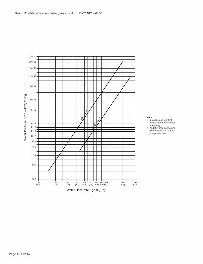
Graph 3. Waterside economizer pressure drop SWT018C – 040C
Note:1. Includes coil, control
valves and interconnect-ing piping.
2. Add this P to condenserP to obtain unit P for
pump selection.
( 6 ) 2
( 9 ) 3
( 1 2 ) 4
( 1 5 ) 5
( 1 8 ) 6
( 2 1 ) 7
( 2 4 ) 8
( 2 7 ) 9
( 3 0 ) 1 0
( 4 5 ) 1 5
( 6 0 ) 2 0
( 9 0 ) 3 0
( 1 5 0 ) 5 0
( 1 2 0 ) 4 0
2 0 ( 1 . 2 )
3 0 ( 1 . 9 )
4 0 ( 2 . 5 )
5 0 ( 3 . 2 )
6 0 ( 3 . 8 )
7 0 ( 4 . 4 )
8 0 ( 5 . 1 )
9 0 ( 5 . 7 )
1 0 0 ( 6 . 3 )
1 5 0 ( 9 . 5 )
2 0 0 ( 1 2 . 6 )
0 1
8
C
–
0
2
8
C
0 3
5
C
–
0
4
0
C
W a t e r F l o w R a t e – g p m ( L / s )
W
a t
e
r
P
r e
s
s
u
r e
D
r o
p
–
(
k
P
a
)
f
t
.
w
. g
.
( 1 8 0 ) 6 0
( 2 1 0 ) 7 0

IM 623 / Page 11
Graph 4. Hot water coil pressure drop SWT018C – 040C
Note:Includes coil, control valvesand interconnecting piping.
( 9 ) 3
2 0 ( 1 . 2 )
3 0 ( 1 . 9 )
4 0 ( 2 . 5 )
5 0 ( 3 . 2 )
6 0 ( 3 . 8 )
8 0 ( 5 . 1 )
1 0 0 ( 6 . 3 )
1 5 0 ( 9 . 5 )
( 1 2 ) 4
( 1 5 ) 5
( 1 8 ) 6
( 2 4 ) 8
( 3 0 ) 1 0
( 6 0 ) 2 0
( 9 0 ) 3 0
( 1 2 0 ) 4 0
( 1 5 0 ) 5 0
( 1 8 0 ) 6 0
( 2 1 0 ) 7 0
W a t e r F l o w R a t e – g p m ( L / s )
W
a t
e
r
P
r e
s
s
u
r e
D
r o
p
–
(
k
P
a
)
f
t
.
w
. g
.
0 1
8
C 0 2
3
C
0 3
5
C 0 2
8
C
0 4
0
C

Page 12 / IM 623
Graph 5. Water regulating valve pressure drop SWT018C – 040C
2 0 ( 1 . 2 )
3 0 ( 1 . 9 )
4 0 ( 2 . 5 )
5 0 ( 3 . 2 )
6 0 ( 3 . 8 )
7 0 ( 4 . 4 )
8 0 ( 5 . 1 )
9 0 ( 5 . 7 )
1 0 0 ( 6 . 3 )
1 5 0 ( 9 . 5 )
2 0 0 ( 1 2 . 6 )
0 1
8
C
–
0
2
8
C
0 3
5
C
–
0
4
0
C
( 3 ) 1
( 6 ) 2
( 9 ) 3
( 1 2 ) 4
( 1 5 ) 5
( 1 8 ) 6
( 2 1 ) 7
( 2 4 ) 8
( 2 7 ) 9
( 3 0 ) 1 0
( 4 5 ) 1 5
( 6 0 ) 2 0
( 7 5 ) 2 5
( 9 0 ) 3 0
( 1 0 5 ) 3 5
( 1 2 0 ) 4 0
W a t e r F l o w R a t e – g p m ( L / s )
W
a t
e
r
P
r e
s
s
u
r e
D
r o
p
–
(
k
P
a
)
f
t
.
w
. g
.
Note:Includes control valves andinterconnecting piping.

IM 623 / Page 13
Duct ConnectionsSupply Air
For connection of supply ductwork directly to the unit, a ductcollar must first be mounted at the fan outlet, avoiding themounting screws located around the perimeter of the fandischarge opening. Fan discharge opening sizes are indi-cated on the unit dimensional drawings. When connectingductwork to the unit, a canvas type connecting collar isrecommended. To maintain specified fan performance, two-fan units should incorporate a properly designed “pants”duct connection (refer to Figure 5).
Units are available in two fan configurations as shown inFigure 6. Duct take-offs which go opposite to the direction offan rotation will result in an associated system effect loss andreduced fan performance.
If a field fabricated plenum is used, duct take-off locationsshould again be correctly oriented to the rotation of the fanto minimize system losses. Refer to unit dimensional drawingsfor plenum mounting size requirements. Canvas type connec-tors are recommended at the duct connection to the plenum.
Figure 6. Discharge duct configurations
R e t u r n A i r
F I
L T
E
R
S
E
C
T
I
O
N
E
C
O
N
O
M
I
Z
E
R
E
V
A
P
O
R
A T
O
R
H
E
A T
E
R
E
L
E
C
T
R
I
C
A
L
P
A
N
E
L
2 . 0 ( 5 1 )
R e t u r n A i r
F I
L T
E
R
S
E
C
T
I
O
N
E
C
O
N
O
M
I
Z
E
R
E
V A
P
O
R
A
T O
R
H
E
A T
E
R
E
L
E
C
T
R
I
C
A
L
P
A
N
E
L
2 . 0 ( 5 1 )
F r o n t D i s c h a r g e
B a c k D i s c h a r g e
Figure 5. Two-fan unit top detail
{ *
1 5 °
* E l b o w s s h o u l d n o t b e c l o s e r t h a n 1 1 / 2 t o 2 1 / 2 t i m e s t h e l a r g e s t d i m e n s i o n o f f a n d i s c h a r g e o p e n i n g .
“ P a n t s ” D u c t C o n n e c t i o n

Page 14 / IM 623
Return AirAir return to the unit can be arranged in different ways.
1. Ducted returnReturn ductwork may be attached to the 2" flange aroundthe perimeter of unit’s return air opening (refer to Figure 7).A canvas type duct connecting collar is recommended. Allductwork connected to the unit should be of adequatesize and construction for the application. A canvas typeconnector is also recommended where the duct pen-etrates the machine room wall(s). This will prevent vibra-tion generated by air movement in the duct from beingtransmitted out to the occupied spaces.
Note: Do not obstruct unit access panel located belowthe return opening.
Note: For units with ducted return, connect the openport on the clogged filter switch (PC5) to the return air duct.
2. Free returnThe mechanical equipment room may be used as a returnplenum with no hard connection at the unit.
Note: Some building codes do not allow the use of themechanical room as a return plenum. Applicable localcodes should be checked for each installation.
Figure 7. Return duct connections
G x H R e t u r n A i r O p e n i n g 2 . 0 T Y P
( 5 1 )
1 . 0 ( 2 5 ) N e o p r e n e I s o l a t i o n P a d s s h i p p e d s e p a r a t e l y
2 6 . 6 3 ( 6 7 6 )
B a c k E l e v a t i o n F o r d i m e n s i o n s G & H , s e e p a g e 1 4 .

IM 623 / Page 15
Physical DataTable 2. SWT018C-040C English units
DATASWT MODEL SIZE
018C 023C 028C 035C 040CCOMPRESSORQuantity 2, 3, 4 3, 4 4 4 4Size (see application chart, Table 4)EVAPORATOR COILFace area (in2) 11.8 15.3 18.9 23.3 26.3Rows 6 6 6 6 6FPI 12 12 12 12 12PERFORMANCENominal tons 13.6 19.7 25.8 31.1 35.6EER 14.2 13.8 13.0 13.6 12.7WATERSIDE ECONOMIZER COILFace area (in2) 11.8 15.3 18.9 23.3 26.3Rows 4 4 4 4 4FPI 12 12 12 12 12Max. working press. 400 400 400 400 400HOT WATER HEATING COILFace area (in2) 9.3 12.8 16.3 20.2 23.8Rows 1 1 1 1 1FPI 12 12 12 12 12ELECTRIC HEATkW 34 34 34 34 34
FILTERS(4) 16x20x4 (4) 16x20x4 (4) 16x20x4 (5) 20x20x4 (5) 20x20x4
(Qty) size (in) (3) 20x20x4 (3) 20x20x4 (3) 20x20x4 (5) 25x20x4 (5) 25x20x4
(2) 25x20x4 (2) 25x20x4 (2) 25x20x4 — —
EVAPORATOR FANQuantity 1 1 1 2 2Size (in) 15 18 18 15-15 15-15Minimum hp 5 7.5 10 10 15Maximum hp 10 15 20 20 25Min. Design cfm, CV 2950 3825 4725 5825 6575Min. Design cfm, VAV 4720 6120 7560 9320 10520Max. Design cfm 7080 9180 11340 13980 15780CONDENSERQuantity 2, 3, 4 3, 4 4 4 4W.S. working press. 400 400 400 400 400Min. entering temp. 55°F 55°F 55°F 55°F 55°F
Table 2a. SWT018C-040C SI units
DATASWT MODEL SIZE
018C 023C 028C 035C 040CCOMPRESSORQuantity 2, 3, 4 3, 4 4 4 4Size (see application chart, Table 4)EVAPORATOR COILFace area (m2) 1.10 1.42 1.76 2.16 2.44Rows 6 6 6 6 6FPI 12 12 12 12 12PERFORMANCENominal tons 13.6 19.7 25.8 31.1 35.6EER 14.2 13.8 13.0 13.6 12.7WATERSIDE ECONOMIZER COILFace area (m2) 1.10 1.42 1.76 2.16 2.44Rows 4 4 4 4 4FPI 12 12 12 12 12Max. working press. 400 400 400 400 400HOT WATER HEATING COILFace area (m2) 0.9 1.2 1.5 1.9 2.2Rows 1 1 1 1 1FPI 12 12 12 12 12ELECTRIC HEATkW 34 34 34 34 34
FILTERS(4) 406x508x102 (4) 406x508x102 (4) 406x508x102 (5) 508x508x102 (5) 508x508x102
(Qty) size (mm) (3) 406x508x102 (3) 406x508x102 (3) 406x508x102 (5) 635x508x102 (5) 635x508x102
(2) 635x508x102 (2) 635x508x102 (2) 635x508x102 — —
EVAPORATOR FANQuantity 1 1 1 2 2Size (in) 15 18 18 15-15 15-15Minimum hp 5 7.5 10 10 15Maximum hp 10 15 20 20 25Min. Design L/s, CV 310 852 1053 1298 1465Min. Design L/s, VAV 2228 2889 3568 4399 4965Max. Design L/s 3342 4333 5352 6599 7448CONDENSERQuantity 2, 3, 4 3, 4 4 4 4W.S. working press. (Pa) 2.8 2.8 2.8 2.8 2.8Min. entering temp. 13°C 13°C 13°C 13°C 13°C
Table 3. Compressor circuit charge
*REFRIGERANT OIL CHARGECOMPRESSOR CHARGE PER PER CIRCUIT
(HP) CIRCUIT (R-22) (OZ.)
5 9 lbs. 5310 14 lbs. 132
*Charge quantities listed are averages. Actual charge quantity is dependenton individual unit evaporator coil circuiting. Actual charge quantities arestamped on each unit nameplate.
Table 4. Compressor application chart
SWT MODEL COMPRESSOR HORSEPOWER MIN. GPM MAX. GPMSIZE CKT #1 CKT #2 CKT #3 CKT #4 (L/s) (L/s)
5 5 — — 24 (1.5) 42 (2.7)018C 5 5 5 — 36 (2.3) 62 (4.0)
5 5 5 5 48 (3.0) 84 (5.3)5 5 5 — 35 (2.2) 65 (4.1)
023C 5 5 5 5 48 (3.0) 84 (5.3)5 5 5 5 58 (3.7) 102 (6.4)5 5 5 5 48 (3.0) 84 (5.3)
028C 5 5 5 10 58 (3.7) 102 (6.4)5 5 10 10 68 (4.3) 119 (7.5)5 5 5 10 58 (3.7) 102 (6.4)5 5 10 10 68 (4.3) 119 (7.5)
035C5 10 10 10 78 (4.9) 137 (8.7)
10 10 10 10 88 (5.6) 154 (9.7)5 5 5 10 58 (3.7) 102 (6.4)5 5 10 10 68 (4.3) 119 (7.5)
040C5 10 10 10 78 (4.9) 137 (8.7)
10 10 10 10 88 (5.6) 154 (9.7)
Page 16 / IM 623
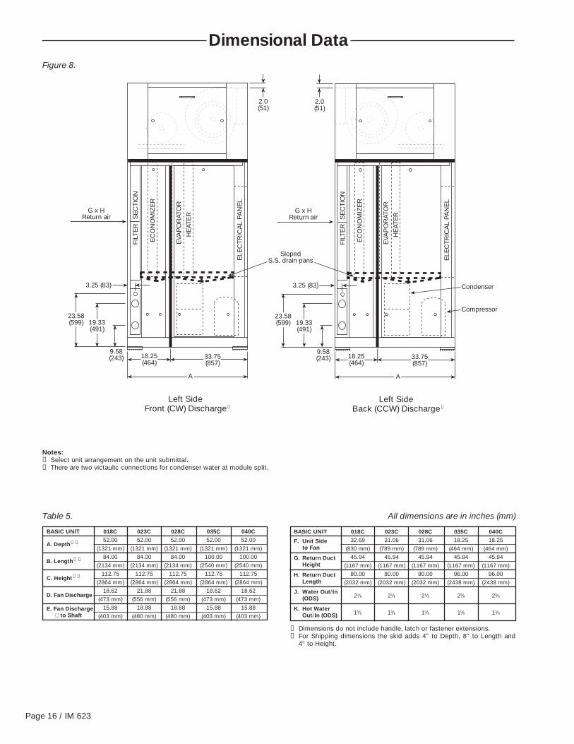
Dimensional DataFigure 8.
Notes:➀ Select unit arrangement on the unit submittal.➁ There are two victaulic connections for condenser water at module split.
G x HReturn air
3.25 (83)
9.58(243)
19.33(491)
23.58(599)
18.25(464)
33.75(857)
A
FILT
ER
SE
CTI
ON
EC
ON
OM
IZE
R
EVA
PO
RAT
OR
HE
ATE
R
ELE
CTR
ICA
L PA
NE
L
SlopedS.S. drain pans
2.0(51)
G x HReturn air
3.25 (83)
9.58(243)
19.33(491)
23.58(599)
18.25(464)
33.75(857)
A
FILT
ER
SE
CTI
ON
EC
ON
OM
IZE
R
EVA
PO
RAT
OR
HE
ATE
R
ELE
CTR
ICA
L PA
NE
L
Condenser
2.0(51)
Compressor
BASIC UNIT 018C 023C 028C 035C 040C
A. Depth➀ ➁ 52.00 52.00 52.00 52.00 52.00
(1321 mm) (1321 mm) (1321 mm) (1321 mm) (1321 mm)
B. Length➀ ➁ 84.00 84.00 84.00 100.00 100.00
(2134 mm) (2134 mm) (2134 mm) (2540 mm) (2540 mm)
C. Height➀ ➁ 112.75 112.75 112.75 112.75 112.75
(2864 mm) (2864 mm) (2864 mm) (2864 mm) (2864 mm)
D. Fan Discharge18.62 21.88 21.88 18.62 18.62
(473 mm) (556 mm) (556 mm) (473 mm) (473 mm)
E. Fan Discharge 15.88 18.88 18.88 15.88 15.88⊥ to Shaft (403 mm) (480 mm) (480 mm) (403 mm) (403 mm)
BASIC UNIT 018C 023C 028C 035C 040C
F. Unit Side 32.69 31.06 31.06 18.25 18.25to Fan (830 mm) (789 mm) (789 mm) (464 mm) (464 mm)
G. Return Duct 45.94 45.94 45.94 45.94 45.94Height (1167 mm) (1167 mm) (1167 mm) (1167 mm) (1167 mm)
H. Return Duct 80.00 80.00 80.00 96.00 96.00Length (2032 mm) (2032 mm) (2032 mm) (2438 mm) (2438 mm)
J. Water Out/In(ODS) 21⁄8 21⁄8 21⁄8 25⁄8 25⁄8
K. Hot WaterOut/In (ODS) 15⁄8 15⁄8 15⁄8 15⁄8 15⁄8
➀ Dimensions do not include handle, latch or fastener extensions.➁ For Shipping dimensions the skid adds 4" to Depth, 8" to Length and
4" to Height.
Left Side Front (CW) Discharge➀
Left Side Back (CCW) Discharge➀
Table 5. All dimensions are in inches (mm)
IM 623 / Page 17
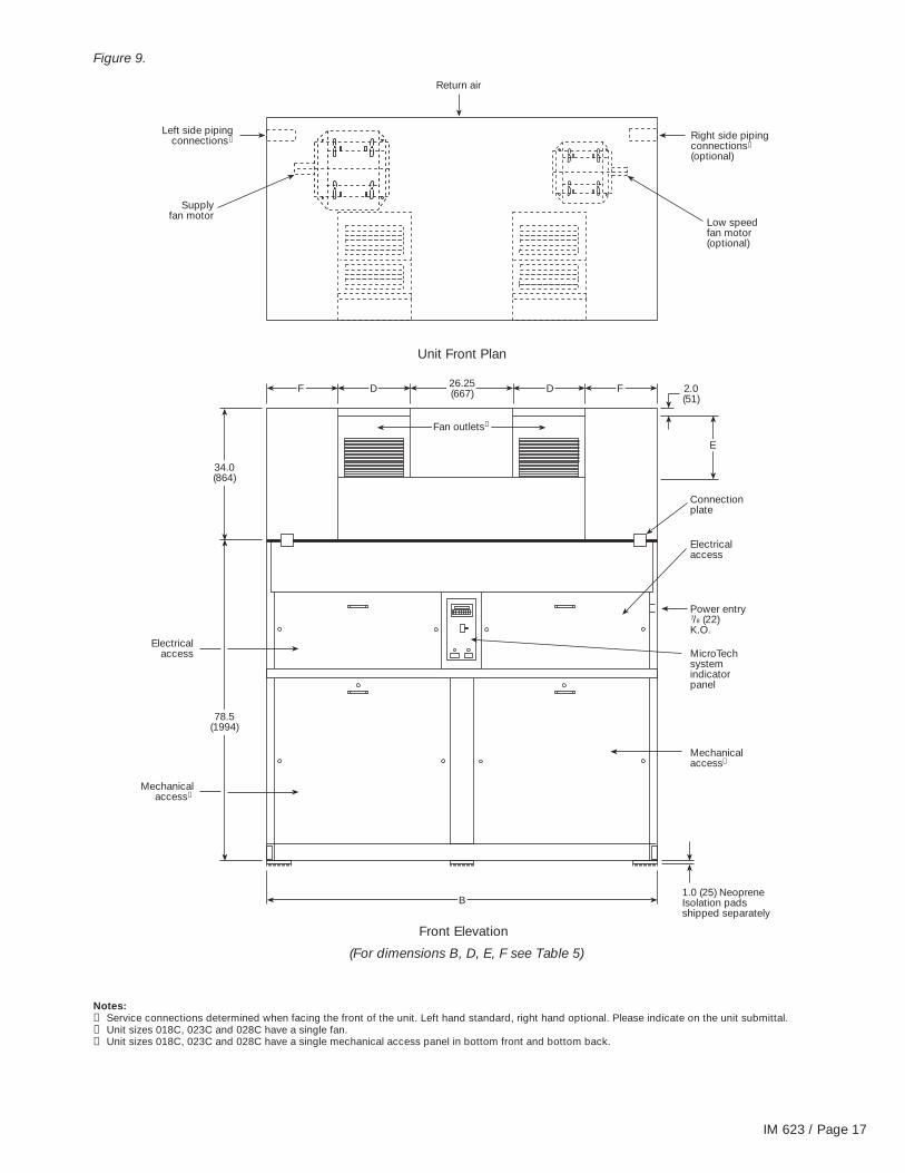
Figure 9.
Electricalaccess
Mechanicalaccess
Supplyfan motor
Left side pipingconnections➂ Right side piping
connections(optional)
➂
Return air
Low speedfan motor(optional)
Unit Front Plan
Front Elevation
Connectionplate
Electricalaccess
Power entry /8 (22)K.O.7
MicroTechsystemindicatorpanel
Mechanicalaccess➄
1.0 (25) NeopreneIsolation padsshipped separately
B
➄
78.5(1994)
34.0(864)
Fan outlets➃
F D D F26.25(667)
E
2.0(51)
(For dimensions B, D, E, F see Table 5)
Notes:➂ Service connections determined when facing the front of the unit. Left hand standard, right hand optional. Please indicate on the unit submittal.➃ Unit sizes 018C, 023C and 028C have a single fan.➄ Unit sizes 018C, 023C and 028C have a single mechanical access panel in bottom front and bottom back.

Page 18 / IM 623
Figure 10.
Notes:➅ Filters are removable from the rear of the unit or through a side filter access door, located on the piping connection side.➆ Length will be increased by approximately 3.5" (89mm), for piping connections when water economizer option is ordered.➇ Mechanical access panel(s) in the back of the unit start 2" (51mm) below return duct opening. Do not obstruct the access panel(s).➈ There are two access doors on 018C, 023C and 028C instead of three as shown.➉ All dimensions are given in inches with millimeters in parentheses.¡ All dimensions ±0.25" (6.4mm).
For dimensions B, C, G, H, J, K see Table 5)
G x H R e t u r n a i r o p e n i n g
M e c h a n i c a l a c c e s s
M e c h a n i c a l a c c e s s
❻
➇
C
2 . 0 T Y P ( 5 1 )
2 6 . 6 3 ( 6 7 6 )
1 . 0 ( 2 5 ) N e o p r e n e I s o l a t i o n p a d s s h i p p e d s e p a r a t e l y
B
C o n n e c t i o n p l a t e
B a c k E l e v a t i o n
L e f t S i d e
M a i n F i l t e r / w a t e r e c o n o m i z e r
L i f t i n g r o d ( b y o t h e r s )
P l a c e t h r o u g h b a s e c h a n n e l
( J ) W a t e r i n
( J ) W a t e r o u t 1 . 1 2 ( 2 8 ) O D S d r a i n
G x H R e t u r n a i r
A A
( K ) H o t w a t e r i n
2 3 . 8 1 ( 6 0 5 )
( K ) H o t w a t e r o u t
3 6 . 5 ( 9 2 7 )
1 0 . 3 8 ( 2 6 4 )
S e c t . A - A M a i n a n d f i l t e r / w a t e r s i d e
e c o n o m i z e r m o d u l e c o n n e c t i o n

IM 623 / Page 19
Unit WeightsTable 6. Unit and components weight – lbs. English units
COMPONENTUNIT SIZE
018C 023C 028C 035C 040CMAIN COOLING/HEATING SECTIONMain Base 946 946 946 1045 10456 Row DX Coil 250 294 347 417 450Comp./Cond. Water(2) 5 hp 26 560 — — — —(3) 5 hp 35 705 705 — — —(4) 5 hp 43 856 856 856 856 —(3) 5, (1) 10 hp 57 — 987 987 987 987(2) 5, (2) 10 hp 66 — — 1105 1105 1105(1) 5, (3) 10 hp 74 — — — 1233 1233(4) 10 hp 95 — — — 1368 1368Hot Water Coil, 1 Row, 12 fpi➁ 71 97 119 130 152HW Coil Water Weight 16 20 23 28 32Electric Heat - 34 kW 20 20 20 20 20Skid for Main 99 99 99 115 115FILTER/WATERSIDE ECONOMIZER SECTIONBase 368 368 368 428 428Water Economizer Coil 4 Row➀ 266 298 340 393 410Economizer Water Weight 51 65 75 94 111FAN SECTIONFan & Frame 900 930 930 1120 1120Skid for Fan Section 98 98 98 115 115Supply Fan Motors3 hp Open Dripproof 71 — — — —5 hp Open Dripproof 82 — — — —71⁄2 hp Open Dripproof 124 124 — — —10 hp Open Dripproof 144 144 144 144 —15 hp Open Dripproof — 185 185 185 18520 hp Open Dripproof — — 214 214 21425 hp Open Dripproof — — — — 2663 hp Totally Enclosed 72 — — — —5 hp Totally Enclosed 85 — — — —71⁄2 hp Totally Enclosed 140 140 — — —10 hp Totally Enclosed 170 170 170 170 —15 hp Totally Enclosed — 235 235 235 23520 hp Totally Enclosed — — 300 300 30025 hp Totally Enclosed — — — — 330
➀ Water economizer weight includes valves and piping.➁ Hot water coil weight includes valve piping.
Table 6a. Unit and components weight – kg SI units
COMPONENTUNIT SIZE
018C 023C 028C 035C 040CMAIN COOLING/HEATING SECTIONMain Base 429 429 429 474 4746 Row DX Coil 113 133 157 189 204Comp./Cond. Water(2) 5 hp 12 254 — — — —(3) 5 hp 16 320 320 — — —(4) 5 hp 20 388 388 388 388 —(3) 5, (1) 10 hp 26 — 448 448 448 448(2) 5, (2) 10 hp 30 — — 501 501 501(1) 5, (3) 10 hp 34 — — — 559 559(4) 10 hp 43 — — — 621 621Hot Water Coil, 1 Row, 12 fpi➁ 32 44 54 59 69HW Coil Water Weight 7 9 10 13 15Electric Heat - 34 kW 9 9 9 9 9Skid for Main 45 45 45 52 52FILTER/WATERSIDE ECONOMIZER SECTIONBase 167 167 167 194 194Water Economizer Coil 4 Row➀ 121 135 154 178 186Economizer Water Weight 23 29 34 43 50FAN SECTIONFan & Frame 408 422 422 508 508Skid for Fan Section 44 44 44 52 52Supply Fan Motors3 hp Open Dripproof 32 — — — —5 hp Open Dripproof 37 — — — —71⁄2 hp Open Dripproof 56 56 — — —10 hp Open Dripproof 65 65 65 65 —15 hp Open Dripproof — 84 84 84 8420 hp Open Dripproof — — 97 97 9725 hp Open Dripproof — — — — 1213 hp Totally Enclosed 33 — — — —5 hp Totally Enclosed 39 — — — —71⁄2 hp Totally Enclosed 64 64 — — —10 hp Totally Enclosed 77 77 77 77 —15 hp Totally Enclosed — 107 107 107 10720 hp Totally Enclosed — — 136 136 13625 hp Totally Enclosed — — — — 150
➀ Water economizer weight includes valves and piping.➁ Hot water coil weight includes valve piping.

Page 20 / IM 623
Table 7. Compressor amp values
COMPRESSOR 208/60/3 230/60/3 400/50/3 460/60/3 575/60/3HP RLA LRA RLA LRA RLA LRA RLA LRA RLA LRA 5 16.2 156 17.9 156 8.1 70 8.1 70 6.5 5410 30.8 255 27.8 255 13.9 127 13.9 127 11.3 100
Table 8. Electric heat
SWT208/60/3 230/60/3 400/50/3 460/60/3 575/60/3
kW MBH FLA kW MBH FLA kW MBH FLA kW MBH FLA kW MBH FLA018C – 040C 27.8 95 77.2 34 116 85.6 25.7 88 37.2 34 116 42.8 34 116 34.2
Table 9. Supply fan motor data
HORSEPOWER TYPE 208/60/3 230/60/3 400/50/3➀ 460/60/3 575/60/3ODP FLA FLA FLA FLA FLA
Standard 9.5 9.0 4.5 4.5 3.8 3 High Efficiency 8.7 7.6 3.6 3.8 3.1
Premium Efficiency 8.4 7.4 3.7 3.7 2.9Standard 15.2 13.6 6.8 6.8 5.9
5 High Efficiency 14.1 13.2 6.6 6.6 5.3Premium Efficiency 13.7 11.9 6.0 6.0 4.8
Standard 22.0 21.0 10.5 10.5 8.471⁄2 High Efficiency 22.1 19.2 9.6 9.6 7.7
Premium Efficiency 22.0 18.7 9.3 9.3 7.5Standard 26.4 25.0 12.5 12.5 10.4
10 High Efficiency 28.1 24.4 12.2 12.2 9.8Premium Efficiency 28.0 24.2 12.1 12.1 9.7
Standard 49.5 38.0 19.0 19.0 16.015 High Efficiency 42.7 37.2 18.6 18.6 14.9
Premium Efficiency 41.2 35.8 17.9 17.9 14.3Standard 53.0 48.6 24.3 24.3 20.0
20 High Efficiency 55.1 48.0 24.0 24.0 19.2Premium Efficiency 54.0 46.6 23.3 23.3 18.6
Standard 66.0 63.0 31.5 31.5 26.025 High Efficiency 69.9 60.8 30.4 30.4 24.3
Premium Efficiency 65.8 57.2 28.6 28.6 22.9
Note:➀ 460/60/3 motors are used. Derate nameplate HP to 0.83 to obtain actual HP.
Field WiringGeneral
Wiring must comply with all applicable codes and ordi-nances. Warranty is voided if wiring is not in accordance withspecifications. An open fuse indicates a short, ground oroverload. Before replacing a fuse or restarting a compressoror fan motor, the trouble must be found and corrected.Copper wire is required for all power lead terminations.
A single power terminal block is provided and wiring
within the unit is done in accordance with the NationalElectric Code. All branch circuits within the control panel areindividually fused. A single field supplied disconnect is requiredor a unit mounted disconnect can be ordered with the unit.
A 7⁄8" knockout is located on the ride hand unit upright forlocating unit power entry.
24V field connections are suitable for Class II wiring.
Unit DisconnectDisconnecting means are addressed by Article 440 of theNational Electric Code (NEC) which requires “disconnectingmeans capable of disconnecting air conditioning and refrig-erant equipment including motor-compressors, and control-lers, from the circuit feeder.” The disconnect switch should
be selected and located within the NEC guidelines. Locationrequirements per NEC are that the disconnect be located ina readily accessible position within sight (50 feet) of the unit.
A factory mounted disconnect is available.

IM 623 / Page 21
Supply Power Wiring1. Units require three-phase supply leads.
2. Allowable voltage tolerances:a. 60 Hertz
Nameplate 208V: min. 187V, max. 229VNameplate 230V: min. 207V, max. 253VNameplate 460V: min. 414V, max. 506VNameplate 575V: min. 518V, max. 632V
b. 50 HertzNameplate 400V: min. 342V, max. 418V
3. Power lead wire sizing:a. For units with cooling capability (all concurrent loads)
with or without hot water heating and circuits withmotor loads only:
MCA = 1.25 (largest motor RLA or FLA) + other loads+ 2 amps
b. For units with cooling capability and non-concurrentelectric heat capability:
In cooling mode, the loads will be composed ofsupply fan motor and compressors. In heating mode,the loads will be composed of supply fan motor andelectric heater. The MCA is calculated for unit runningin either mode; the highest value obtained is used forthe MCA.
1) For unit in cooling mode:MCA = 1.25 (largest motor RLA or FLA) + other loads
+ 2 amps
2) For unit in heating mode:MCA = 1.25 (electric heat FLA + supply fan FLA)
+ 2 amps
4. Size wires in accordance with Table 310-16 or 310-19 orthe National Electric Code.
5. Wires should be sized for a maximum of 3% voltage drop.
Lug Sizes for Single Disconnect or Power Block
Table 10. Single disconnect
UNIT VOLTAGE SIZE (AMPS)018 – 028 208/230 225018 – 028 400/460 100018 – 028 575 100035 – 040 208/230 225035 – 040 400/460 150
035 575 100040 575 150
Table 11. Lug sizes for single disconnect
DISCONNECT SIZE LUG SIZE100 #6 – 2/0150 #2 – 3/0225 #3 – 300 MCM
Table 12. Lug sizes for power block
UNIT VOLTAGE LUG SIZE018 – 040 All #6 – 400 MCM

Page 22 / IM 623
Control CenterAll electrical controls are enclosed in a central control centerlocated at the front of the unit. The control center is dividedinto two separate compartments, high and low voltage. Theupper compartment houses the high voltage componentsand can be accessed through the two “Electrical Access”panels indicated on the dimensional drawing. Behind theseaccess panels are hinged dead front panels for furtheroperator safety. High voltage components include fan motorcontactor (M10) and fusing (F10), fan motor overload (OL10),compressor contactors (M1 to M4), compressor fusing (F1 toF4), electric heat contactors (M11 to M14), high to lowvoltage transformer (T1), power block (PB1) and optionaldisconnect switch (DS1). If the optional disconnect switch isprovided, the switch handle is visible and accessible withoutremoving any safety or access panels.
Low voltage components are located in the lower com-partment and are accessed through the “Mechanical Ac-cess” panel(s), as shown on the dimensional drawing. Lowvoltage components include the MicroTech main controlboard (MCB), a printed circuit input board, a printed circuitoutput board, duct static pressure sensor (SPS1), duct highlimit switch (DHL1), clogged filter switch (PC5), proof ofairflow switch (PC7), MicroTech reset switch and Class IIwiring terminals. Class II are connections made at the inputand output circuit boards.
Located on the face of the unit is the interactive MicroTechkeypad/display, unit switch, system indicator light and powerindicator.
Figure 11. Typical control center layout high and low voltage compartments

IM 623 / Page 23
Electrical Legend
Model SWP/SWT LegendDesignation Description Standard Location
ACT1 ..................... Actuator, Variable Inlet Vane ................... Supply Air Fan Housing
ACT2 ..................... Actuator, Bypass Valve ............................ Near Condenser
ACT3 ..................... Actuator, Water Economy Valve .............. Near Condenser Water Inlet
ACT4 ..................... Acutator, Hot Water or Steam Valve ....... Near Steam or Hot Water Coil
ACT5 ..................... Actuator, Chilled Water Valve .................. Near Chilled Water Inlet
AMPS1 .................. Low Speed Fan Motor Current Sensor ...... Control Box
DHL ....................... Duct High Limit Switch ............................. Control Box
DS ......................... Disconnect Switch .................................... Control Box
EWT ...................... Ent. Cond. Water Temp. Sensor .............. Condenser Water Inlet
F1-27 .................... Fuses ......................................................... Control Box
FB1-6 .................... Fuse Blocks .............................................. Control Box
FB10-12 ................ Fuse Blocks .............................................. Control Box
FP1-6 .................... Frost Protection Switches ........................ Evaporator Coil
FS1 ....................... Freezestat Switch ..................................... Near Filters
HL13A, 13B, ......... High Limit Switches for ............................ On Elec. Heater Jct. BoxHL14A, 14B ...... HTR11, 15, 12, 16, respectively 1-6
HP1-6 ................... High Pressure Switches ........................... On Compr. Disch. Port
HS ......................... Humidity Sensor ....................................... Conditioned Space
HTR11, 12, 15, 16 .. Electric Heaters ........................................ DX Coil
Input Board .......... MicroTech Input Conditioning .................. Control Box
K0 ......................... Relay, Alarm .............................................. Output Board
K1-4, K16-17 ........ Relay, Compressors ................................. Output Board
K5 ......................... Relay, Bypass ........................................... Output Board
K6 ......................... Relay, VAV/Heat ....................................... Output Board
K7 ......................... Relay, Water Econ. Close ........................ Output Board
K8 ......................... Relay, Water Econ. Open ......................... Output Board
K9 ......................... Relay, VAV Close ...................................... Output Board
K10 ....................... Relay, VAV Open ...................................... Output Board
K11 ....................... Relay, Elec. Heat Stage 1 HW/S Close ... Output Board
K12 ....................... Relay, Elec. Heat Stage 2 HW/S Open .... Output Board
K13 ....................... Relay, Fan On ........................................... Output Board
K14 ....................... Relay, Outside Air Damper ....................... Output Board
K15 ....................... Relay, Fan Operation ................................ Output Board
K24 ....................... Relay, Smoke Start ................................... Output Board
K25 ....................... Relay, Remote Shutdown ........................ Output Board
K26 ....................... Relay, Control ........................................... Output Board
K27 ....................... Relay, Unit Shutdown ............................... Output Board
K28 ....................... Relay, Low Speed Fan Motor .................. Output Board
K29 ....................... Relay, Fan Motor ...................................... Output Board
LP1-6 .................... Low Pressure ............................................ On Compr. Suction Port
Designation Description Standard Location
LWT ...................... Leaving Condenser Water Temp. ............ Condenser Water Pipe
M1-6 ..................... Contactor, Compressor Motor ................. Control Box
M8 ......................... Contactor, Low Speed Fan Motor ........... Control Box
M10 ....................... Contactor, Fan Motor ............................... Control Box
M11, M12 ............. Contactor, Elec. Heater Control .............. Control Box
M13, M14 ............. Contactor, Elecv. Safety Control ............. Control Box
MAT ...................... Mixed Air Temp. Sensor ........................... Behind Filters
MP1-6 ................... Solid-State Motor Protection ................... Compr. Junction Box(10 hp & higher)
OAE ....................... Outside Air Enthalpy Switch .................... External
OAT ....................... Outside Air Temp. Sensor ........................ External
OL8, OL10 ............ Fan Motor Overload Relays ..................... Control Box
Output Board ....... Output Conditioning for MicroTech .......... Control Box
PB1 ....................... Power Distribution Block ......................... Control Box
PC5 ....................... Clogged Filter Switch ............................... Control Box
PC7 ....................... Airflow Switch ........................................... Control Box
PSR ....................... Pressure Sensor, Refrigerant ................... Liq. Shutoff Valve, Ckt. #1
RAT ....................... Return Air Temp. Sensor .......................... External
S1 .......................... MicroTech Reset Switch ........................... Control Box
S2 .......................... Unit Switch ................................................ Unit Front
SAT ....................... Supply Air Temp. Sensor ......................... Near Fan Inlet
SD1 ....................... Smoke Detector ........................................ Field Mounted
SPS1, SPS2 ......... Duct Static Pressure Sensor .................... Control Box
T1 .......................... Transformer, Control ................................ Control Box
T2 .......................... Transformer, Control – Class 2 ................ Control Box
T3 .......................... Transformer, Control – MicroTech ........... Control Box
UVP ....................... Undervoltage/Phase Failure Protection ..... Control Box
VEL1 ..................... Velocity Sensor ......................................... Control Box
WF1 ...................... Condenser Water Flow Switch ................ Near Condenser
General Notes:
1. —– —– —– Field Wiring 5. ———200——— Wire Number
2. ———●●———– Terminal 6. ———————– Wire Connector
3. ———●●———– Terminal Field Wired 7. Option
4. ———●———— Terminal PC Board, 8. ———<<——— Plug ConnectorFactory Wired

Page 24 / IM 623
Typical Wiring SchematicsPower Schematic

IM 623 / Page 25
Control Schematic, Input

Page 26 / IM 623
Control Schematic, Output

IM 623 / Page 27
Standard ControlsHigh Pressure Switches
The high pressure switch (HP1-HP4) is a single pole pressureactivated device that opens on a pressure rise. When theswitch opens it de-energizes the compressor circuit, shut-ting down the compressor. The MicroTech controller willdisplay an alarm condition. Once the cause of the fault hasbeen identified and corrected the unit may be manually resetthrough the MicroTech keypad/display interface. The high pres-
sure switch is located at the top of the compressor on thedischarge connection. To check the control, shut off waterflow to the condensers and observe the cutout point on ahigh pressure gauge. The high pressure control should openat 360 psig and close at 300 psig. After testing the highpressure control, check the pressure relief device for leaks.
Low Pressure SwitchesThe low pressure switch (LP1-LP4) is a single pole pressureactivated device which closes on a pressure rise. It sensesevaporator pressure and is factory set to close at 60 psig andopen at 35 psig. Compressor operation is not allowed untilthe switch closes. The low pressure switch is an automatic
reset control. If the condition occurs on any one compressorthree times in a 24-hour period, the alarm will have to bemanually reset through the MicroTech keypad/display interfaceto restart the compressor. The low pressure switch is locatedat the bottom of the compressor on the suction connection.
Compressor Motor ProtectorAll compressors are thermally protected. All 10 horsepowerand larger compressors use a solid state protection device(MP1 - MP4) located in the compressor junction box. When-ever the protection system opens the compressor is shutdown for a period of four minutes and an alarm indication ismade at the MicroTech controller. All 5 horsepower com-
pressors have in-line protection. The control automaticallyresets when the alarm condition is removed and the timedelay is satisfied. If the condition occurs on any one com-pressor three times in a 24-hour period, the alarm will haveto be manually reset through the MicroTech keypad/displayinterface to restart the compressor.
Proof of Airflow SwitchA positive proof of airflow switch (PC7) is provided with allunits. The switch is factory set to close at 0.2 inches of H20.The switch has a field adjustable set point range of 0.17 to 5.0inches of H20. Turn adjustment screw clockwise to decreasedifferential pressure setting. Turn adjustment screw counter-clockwise to increase differential pressure setting. In a con-stant volume system, if the fan system is energized and theminimum pressure setting of the switch has not been reached,
the unit will be shut down and a loss of airflow alarm indicatedat the MicroTech controller. For variable air volume units, theunit will shutdown due to loss of airflow only if the airflowswitch is open and the duct static pressure is less than halfthe duct static pressure setpoint. Once the reason for thefault has been corrected, the unit can be manually resetthrough the MicroTech keypad/display interface. PC7 is locatedin the low voltage compartment of the unit control panel.
Frost Protection SwitchesA frost protection switch (FP1-FP4) is used on each refriger-ant circuit to protect against evaporator coil freeze up. Thefrost protection switches are normally closed and open on adrop in temperature. When a frosting condition is sensed thecompressor circuit is shutdown until the condition has beenremoved. The frost protection control is an automatic reset
control. If the condition occurs on any one compressor threetimes in a 24 hour period, the alarm will have to be manuallyreset through the MicroTech keypad/display interface torestart the compressor. The MicroTech control will indicate awarning when a frost condition exists. The temperature sensorsare located on a return bend for each refrigerant circuit.
Clogged Filter SwitchA clogged filter switch (PC5) is provided to indicate when unitfilters are to be changed. The switch is factory set to close at0.6 inches of H2O. The switch has a field adjustable set pointrange of 0.17 to 5.0 inches of H20. Turn adjustment screwclockwise to decrease differential pressure setting. Turnadjustment screw counterclockwise to increase differential
pressure setting. When the filter pressure differential ex-ceeds the switch setpoint, a clogged filter indication is madeat the MicroTech controller. The unit is allowed to continueoperation. PC5 is located in the low voltage compartment ofthe unit control panel.

Page 28 / IM 623
Unit OptionsDuct High Limit
A duct high limit (DHL) pressure control is provided asstandard with all units having variable air volume control. Theduct high limit is intended to protect the ductwork, etc. fromover pressurization caused by tripped fire dampers or acontrol failure. When the duct pressure exceeds the settingof the control, the unit is de-energized via the MicroTechcontroller and an alarm condition indicated. After the reasonfor trip has been identified and corrected, the control can be
reset via the MicroTech keypad/display interface.The duct high limit is preset for a 3.0" w.c. trip point. The
control can be readjusted in the field to match the specificductwork of a project. The switch has a field adjustable setpoint range of 0.17 to 5.0 inches of H20. Turn adjustmentscrew clockwise to decrease differential pressure setting.Turn adjustment screw counterclockwise to increase differ-ential pressure setting.
Phase Fail/Under Voltage ProtectionThe monitor is a microprocessor controlled device whichprovides protection against three-phase electrical motorloss due to low voltage, phase loss, voltage unbalance andphase reversal. The microprocessor constantly monitors thethree-phase line voltages and detects these harmful powerline conditions. Whenever any of these conditions occur, the
SWT controls are deactivated and remain deactivated untilpower line conditions return to an acceptable level. Trip andreset delays have been provided to prevent nuisance trippingdue to rapid power fluctuations. The trip and reset delays arefield adjustable. The monitor also provides a variable linevoltage adjustment.
Duct Static Pressure SensorAll units provided with variable air volume control include afactory mounted static pressure sensor (SPS1). The sensoris factory wired and requires field installation of 1⁄4" I.D.sensor tubing to the selected duct location. Note: Be surethat tubing complies with local code requirements. Flameretardant plastic or metal tubing may be required. Carefullyselect the ductwork sensing point for the pressure sensor.Improper location of the sensing point will result in unsatis-factory operation of the entire variable air volume system.The following guidelines should be adhered to:
1. Sense near the end of long duct runs to ensure that allterminal box take-offs along the run will have adequatestatic pressure to operate.
2. The end of the sensing tube must be perpendicular to theairflow in order to sense only static pressure.
3. The sensing tube should be located in a non-turbulent flowarea of the duct. Keep several duct widths away fromtake-off points, bends or neck downs.
Mounting instructions (see Figure 12)
1. Drill hole in duct at remote sensing point and install arubber grommet. Insert sensing tube 1⁄8" into the duct andsecurely clamp tubing to the duct, being sure not to stressor kink the tubing. The end of the sensing tube must besmooth and cut straight across. An angle cut will affectoperation.
2. Clamp a second tube to the outside of the duct at thelocation of the sensing point.
3. Run both tubes along the ductwork and back to the unit.The tubing may be routed to the pressure sensor (SPS1)by drilling two holes through the unit upright post. Agrommet must be used at each hole to protect the tubingand seal the cabinet. Note: To avoid confusion between“high” and “low” tubing, it is recommended that twodifferent tubing colors be used and that this informationbe recorded, along with the sensing point location, on themaster building blueprints.
4. Connect tubing to the high and low ports on the sensor.
Figure 12.
Building Static Pressure SensorIf a unit has direct building static pressure control capability,static pressure taps must be field installed and connected topressure sensor SPS1 in the unit. This sensor is located onthe control panel.
The two static pressure sensing taps must be carefullylocated and installed. Improper location or installation of thesensing taps will cause unsatisfactory operation. Followingare pressure tap location and installation recommendationsfor both building envelope and lab, or “space within a space”,pressure control applications. The installation must complywith local code requirements.
Fragile sensor fittings. May damage pressure sensor.
If tubing must be removed from a pressure sensor fitting, usecare. Do not wrench the tubing back and forth to remove or thefitting may break off.
T o S e n s o r “ H I ” I n p u t
T u b e C l a m p s
P r e s s u r e S e n s i n g T u b i n g
R u b b e r G r o m m e t
T u b i n g e x t e n d s t h r u a p p r o x . 1 / 8 "
T o S e n s o r “ L O ” I n p u t
IM 623 / Page 29
5. Locate the reference pressure (LO) tap on the roof. Keepit away from the condenser fans, walls, or anything elsethat may cause air turbulence. Mount it high enoughabove the roof so that it is not affected by snow. If thereference tap is not connected to the sensor, unsatisfac-tory operation will result.
6. Use an outdoor static pressure top (Dwyer A306 or equiva-lent) to minimize the adverse effects of wind. Place sometype of screen over the sensor to keep out insects. Looselypacked cotton works well.
7. Route the outdoor tap tube out of the main control panelthrough a small field-cut opening in the edge of the controlwiring raceway cover. Cut this “mouse hole” in the verticalportion of the edge. Seal the penetration to prevent waterfrom entering. Connect the tube to the 1⁄4" LO fitting onsensor SPS1.
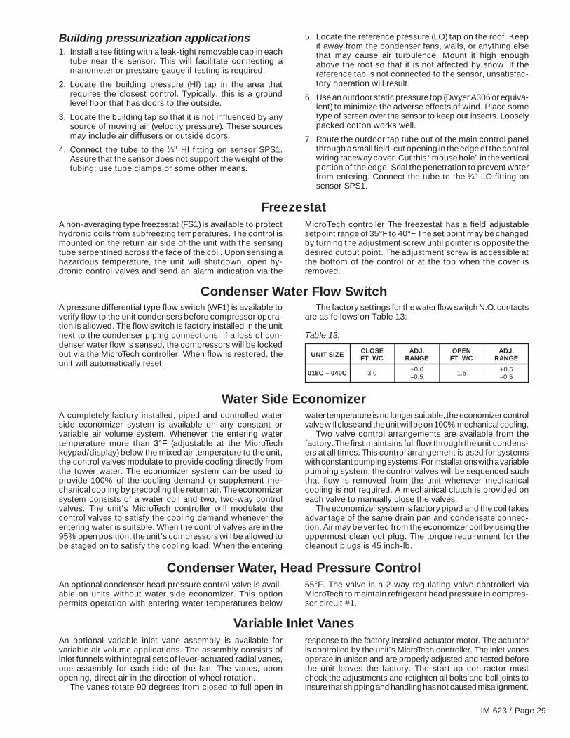
Building pressurization applications1. Install a tee fitting with a leak-tight removable cap in each
tube near the sensor. This will facilitate connecting amanometer or pressure gauge if testing is required.
2. Locate the building pressure (HI) tap in the area thatrequires the closest control. Typically, this is a groundlevel floor that has doors to the outside.
3. Locate the building tap so that it is not influenced by anysource of moving air (velocity pressure). These sourcesmay include air diffusers or outside doors.
4. Connect the tube to the 1⁄4" HI fitting on sensor SPS1.Assure that the sensor does not support the weight of thetubing; use tube clamps or some other means.
FreezestatA non-averaging type freezestat (FS1) is available to protecthydronic coils from subfreezing temperatures. The control ismounted on the return air side of the unit with the sensingtube serpentined across the face of the coil. Upon sensing ahazardous temperature, the unit will shutdown, open hy-dronic control valves and send an alarm indication via the
MicroTech controller The freezestat has a field adjustablesetpoint range of 35°F to 40°F The set point may be changedby turning the adjustment screw until pointer is opposite thedesired cutout point. The adjustment screw is accessible atthe bottom of the control or at the top when the cover isremoved.
Condenser Water Flow SwitchA pressure differential type flow switch (WF1) is available toverify flow to the unit condensers before compressor opera-tion is allowed. The flow switch is factory installed in the unitnext to the condenser piping connections. If a loss of con-denser water flow is sensed, the compressors will be lockedout via the MicroTech controller. When flow is restored, theunit will automatically reset.
The factory settings for the water flow switch N.O. contactsare as follows on Table 13:
Table 13.
UNIT SIZE CLOSE ADJ. OPEN ADJ.FT. WC RANGE FT. WC RANGE
018C – 040C 3.0 +0.0 1.5 +0.5–0.5 –0.5
Water Side EconomizerA completely factory installed, piped and controlled waterside economizer system is available on any constant orvariable air volume system. Whenever the entering watertemperature more than 3°F (adjustable at the MicroTechkeypad/display) below the mixed air temperature to the unit,the control valves modulate to provide cooling directly fromthe tower water. The economizer system can be used toprovide 100% of the cooling demand or supplement me-chanical cooling by precooling the return air. The economizersystem consists of a water coil and two, two-way controlvalves. The unit’s MicroTech controller will modulate thecontrol valves to satisfy the cooling demand whenever theentering water is suitable. When the control valves are in the95% open position, the unit’s compressors will be allowed tobe staged on to satisfy the cooling load. When the entering
water temperature is no longer suitable, the economizer controlvalve will close and the unit will be on 100% mechanical cooling.
Two valve control arrangements are available from thefactory. The first maintains full flow through the unit condens-ers at all times. This control arrangement is used for systemswith constant pumping systems. For installations with a variablepumping system, the control valves will be sequenced suchthat flow is removed from the unit whenever mechanicalcooling is not required. A mechanical clutch is provided oneach valve to manually close the valves.
The economizer system is factory piped and the coil takesadvantage of the same drain pan and condensate connec-tion. Air may be vented from the economizer coil by using theuppermost clean out plug. The torque requirement for thecleanout plugs is 45 inch-lb.
Condenser Water, Head Pressure ControlAn optional condenser head pressure control valve is avail-able on units without water side economizer. This optionpermits operation with entering water temperatures below
55°F. The valve is a 2-way regulating valve controlled viaMicroTech to maintain refrigerant head pressure in compres-sor circuit #1.
Variable Inlet VanesAn optional variable inlet vane assembly is available forvariable air volume applications. The assembly consists ofinlet funnels with integral sets of lever-actuated radial vanes,one assembly for each side of the fan. The vanes, uponopening, direct air in the direction of wheel rotation.
The vanes rotate 90 degrees from closed to full open in
response to the factory installed actuator motor. The actuatoris controlled by the unit’s MicroTech controller. The inlet vanesoperate in unison and are properly adjusted and tested beforethe unit leaves the factory. The start-up contractor mustcheck the adjustments and retighten all bolts and ball joints toinsure that shipping and handling has not caused misalignment.

Page 30 / IM 623
Dual Fan Motor DriveOptional dual, high speed/low speed motors are available forvariable air volume applications. Each motor is on an inde-pendent electrical circuit providing availability of either motorsystem if the other is down for service. Switch over betweenhigh and low speed is accomplished by the unit’s MicroTechcontrol system. The entire assembly is factory adjusted.
Static pressure is controlled by the unit mounted MicroTechcontroller. Indication of current airflow status is available at
the MicroTech controller. High/low speed changeover isaccomplished through the MicroTech DDC controller using asophisticated control scheme which monitors motor powerdraw and system air velocity.
All variable air volume units include field adjustable ducthigh limit safety control to protect ductwork from excessiveduct pressure.
Variable Frequency DriveAs an option, of the SWT can be set up to control a fieldprovided variable frequency drive. A field provided manuallyactivated bypass contactor is recommended to allow systemoperation in the event of drive service.
The SWT controller provides a tri-state digital output tothe VFD and requires a 0-5 VDC analog signal for feedback.Static pressure is controlled by the unit mounted MicroTechcontroller. Indication of current airflow is available at the
MicroTech controller. Static pressure is sensed by one or twofactory mounted duct sensors. The installer provides andinstalls the sensor tubing from unit mounted sensor(s) to ductlocation(s). The static pressure setpoint is keypad adjustablethrough the MicroTech DDC controller.
All variable air volume units include field adjustable ducthigh limit safety control to protect ductwork from excessiveduct pressure.
A factory mounted, nonfused main circuit interrupter fordisconnecting the main electrical power is available. Theswitch is located at the front of the unit on the control panel
and is accessible without unit penetration. The lug sizeinformation is provided in Tables 10 and 11.
Disconnect Switch
Electric HeatOptional electric heat is available. Heat is controlled by theunit’s MicroTech unit controller to maintain setpoint. The heat
has two stages of capacity. The heaters are factory installedand wired including branch fusing and all safety controls.
Hot Water ControlA factory mounted, 1 or 2 row hot water coil is available, withor without factory mounted control valve. The hot watercontrol valve is controlled by the unit’s MicroTech controller
to provide morning warm-up heat or heat for constant volumeapplication.
System Check, Test & Start
Electric shock hazard. Failure to bond the frame of this equipment to the building electrical ground by use of the grounding terminalprovided or other acceptable means may result in electric shock. Disconnect electric power before servicing equipment.
GeneralOnly qualified personnel should perform the start-up andservice of this equipment. A representative of the owner orthe operator should be present during start-up to receiveinstruction in the operation, care and adjustment of the unit.
To assure proper warranty coverage, the unit must be put
through a check, test and start-up procedure. The com-pleted check test and start form (supplied with each unit)must be signed and returned to McQuay International.
Note: Always open power disconnect switch before open-ing service panels.
Battery PackAs an option a battery pack is available. The battery packreceives a trickle charge when electric power is present.When the electric power fails, the battery pack drives the
waterside (airside) economizer valve (actuator) and the by-pass valve closed.

IM 623 / Page 31
Pre Start-up1. Check that the unit is completely and properly installed
with ductwork connected. Check that all constructiondebris is removed and filters are clean.
2. With all electrical disconnects open, check all electricalconnections to be sure they are tight. Although all factoryconnections are tight before shipment, some looseningmay have resulted from shipping vibration.
3. Check all compressor valve connections for tightness toavoid refrigerant loss at start-up. Although all factoryconnections are tight before shipment, some loosening mayhave resulted from shipping vibration. Refer to Table 14for proper valve torque values.
4. Check tightness of setscrews in bearings, drives, and fanwheels. If retightening is needed, make certain fan wheelsare centered between the inlet openings and setscrewsare torqued per Table 15.
5. Check that the fan rotates freely. Check belt tension andalignment.
6. Check that the unit condenser water connections andcondensate drain connections have been made.
7. Before attempting to operate the unit, review the controllayout description to become familiar with the controllocations. Review all equipment service literature and theunit wiring diagrams supplied with each unit. Review op-tional controls to determine which are included in the unit.
8. Make sure that the return air temperature sensor andoptional space temperature sensor, if used, have beeninstalled in the return air duct and that the wiring termina-tions have been made at the unit Input Board.
9. Make sure that entering and leaving condenser watertemperature sensors are mounted.
10. Make sure that the optional duct static pressure sensorSPS1, if used, is connected to the duct with appropriatetubing.
11. Check the voltage of the unit power supply and see thatit is within the ±10% tolerance that is allowed. Phasevoltage unbalance must be within ±2%.
12. Check the unit power supply wiring for adequate ampacityand a minimum insulation rating of 75°C.
13. Verify that all mechanical and electrical inspections havebeen completed per local codes.
14. Open the compressor suction and discharge shutoffvalves until backseated. Always replace valve seal caps.
Table 14. Valve torques
COUPLING GAGE PORT STEM CAP COUPLING NUTNUT SIZE CAP TORQUE TORQUE TORQUE
(INCH) (LBS-FT) (LBS-FT) (LBS-FT)
1.00 7±1 32±2 55±51.25 7±1 32±2 90±101.75 7±1 45±3 205±15
Table 15. Setscrew torque
TORQUE MIN.SETSCREW DIAMETER (LBS-FT)
#10 4.3 1⁄4" 10.0
5⁄16" 20.0 3⁄8" 25.0
Start-upGeneralAll units are factory tested to assure proper operation in the field.
1. Close disconnect switch with switch S2 in the “OFF”position.
2. Power should now be supplied to the MicroTech controllerand the LEDs on MCB1 should follow the normal start-upsequence.
3. Set internal MicroTech timeclock or external timeclock ifused.
4. Set cooling setpoint to a value which will assure a full callfor cooling.
5. Start the auxiliary equipment for the installation such aswater pumps, cooling towers, etc…
Fan start-up1. Place the unit into the “OCC-FAN ONLY” mode through
keypad menu 11.
2. Turn switch S2 to “ON”. The supply air fan should start andrun.
3. Check that fan(s) rotates clockwise when viewed from thedrive side of unit. If it does not, reverse two incomingpower cables at the terminal block or disconnect switchon the unit. If the fan section was shipped attached to thebase sections do not reverse the wires at the fan motorcontactor. The factory assures internal wiring for all mo-tors and scroll compressors rotate in the correct directiononce supply fan rotation check has been made. If the fan
section was shipped separate check for proper rotation atthe supply fan and scroll compressors:
4. If the fan does not run:a. Check the control circuit fuse F1.b. Check control transformer fuse FB7.c. Verify that the fan overload is not tripped.d. Check the fan motor power fuses.e. Trace the circuits.
Compressor start-upWith the supply air fan operational, prepare for compressoroperation. Note: The unit is shipped with the refrigerationservice valves closed. Backseat (open) the suction, dischargeand liquid line valves and replace service caps. Connectservice gauges and crack valves off the backseat position(one turn forward). Verify that the unit has not lost its refrig-erant charge due to shipping damage or leaks.
1. Set Cooling Control Setpoint, menu 13, to a value whichwill assure a call for full cooling.
2. Place unit into the OCC-COOL ONLY mode throughkeypad/display Control Mode menu 11.
3. If desired, the MicroTech internal control timers can bereduced (20 seconds) through the keypad/display Servicemenu 25 (Timers=) by changing the entry from “Normal” to“Fast”. This will reduce the delays associated with normalcontrol action for 15 minutes.
Note: “Fast” timers should only be used to verifysequencing of compressors during start-up. The timermust be returned to “Normal” for proper unit operation.
Page 32 / IM 623
Do not allow compressors to come on repeatedly in the“Fast” timer mode as this may damage compressors and/orwill indicate “Motor Protector Failure” under compressoralarms.
4. The compressors should now start. Start compressorsone at a time, beginning with compressor number 1.Facing the unit, from left to right, compressors are num-bered #1, #3, #4 and #2.
If the compressor motor hums but does not run, verifythat the unit is getting three phase power.
5. Check that the compressors are operating correctly. Thescroll compressors must operate in the proper rotation.Check the compressor discharge line pressure or tem-perature.
Discharge line and compressor head may be hot: Do Not Touch!
After each compressor is started, the discharge pressureand discharge line temperature should increase. If thisdoes not occur, and if the compressor is producing anexceptional amount of noise, the compressor motor maybe operating in the wrong direction. If a problem isencountered, it will be necessary to check all of thecompressors and the supply fan motor. If a single motoris operating backward, check the power wiring for thatmotor and correct any leads that have been interchangedat the contactor or at the motor. If all of the motors areoperating backward, disconnect the unit power supplyand lock it in the OFF position. Switch two leads of thepower supply at the unit power terminal block or discon-nect switch. Reconnect power and check for compressorand supply fan motor operation.
6. The compressors should run continuously. If a compressorcycles on the low pressure switch:a. Verify that the circuit is not low on charge.b. Check for low airflow.c. Check for clogged filters.d. Check for restricted ductwork.e. Check for very low mixed air temperatures to the unit.f. Verify that all the distributor tubes, expansion valve and
liquid line components are feeding the evaporator coil.g. Verify that all fan section access panels are in place.h. Verify that the suction service valves and the liquid line
service valves are completely open.i. Verify that all sensor inputs are connected.
Economizer start-upThe economizer is modulated to maintain the cooling setpoint.With entering water temperature more than 3°F below themixed air return to the unit, place the water sensor in a coldbath if supply water to the unit is too warm, and the unitcalling for cooling, observe that the economizer control valvemodulates open. Readjust control setting or remove the sensorfrom the bath and observe that the economizer control valvedrives closed.
Hot water start-upThe hot water valve is modulated to maintain the dischargeheating setpoint. To verify the hot water valve operation, adjustthe heating setpoint in menu 12. Set the heating setpoint atmenu 12 to a temperature greater than the control tempera-ture plus the dead band. Note: The cooling setpoint must behigher than the heating setpoint. With the heating setpointset properly the hot water valve should modulate open. To closethe hot water valve adjust the heating setpoint in menu 12
below the control temperature minus the dead band. Aftertesting the hot water valve, return the heating setpoint inmenu 12 to its proper setting.
Expansion valve superheat adjustmentIt is very important that superheat is set properly. It should bebetween 10°F and 12°F under full load conditions. Lowerentering air conditions, lower airflow rates and higher con-densing temperatures reduce the load on the expansionvalve. Under reduced load conditions, the superheat couldbe as low as 6°F to 8°F. Insufficient superheat will causeliquid floodback to the compressor and possible liquid slug-ging. Excessive superheat will reduce system performanceand shorten compressor life. Verify that the sensing bulb isproperly located (see Figure 13) and securely strapped to therefrigerant line. Turn the adjusting stem clockwise to increasesuperheat. Adjust the stem (maximum one turn at a time) andobserve the superheat. Allow up to 30 minutes for the systemto rebalance at the final setting.
Figure 13. Water and refrigerant piping schematic
Notes: Water temperature sensor to beinstalled by others in field after the con-denser water connections are made.

IM 623 / Page 33
Variable air volume (VAV) start-upEnter the duct static pressure setpoint value and parametersin the MicroTech Duct Pressure menu 17. When the appro-priate number of VAV terminal boxes are opened by settingdown there respective thermostats, the vanes should go tothe maximum airflow. Upon closing enough VAV boxes bysetting their respective thermostats up, the inlet vanes shouldgo to the minimum airflow position.
Rpm changesAll units are provided with fixed pitch sheaves selected forthe specified operating conditions. If a new fan RPM selec-tion is required a new sheave selection will need to be fieldinstalled. Adjust belt tension as described below.
Drive sheave alignment and belt tensionDrive sheave alignment should be checked using the four-point method shown in Figure 14. When measuring from thestraight edge to the belt, the dimensions A, B, C and D mustbe equal for correct alignment.
Check drive for adequate run-in belt tension. Use thefollowing procedure to determine proper belt tension:
Step 1. Measure span length (t) as shown in Figure 15.
Step 2. From Figure 15, the deflection height (h) is always1⁄64" per inch of span length (t). For example, a 32"span length would require a deflection of 32⁄64" or 1⁄2".
Step 3. Determine the minimum and maximum recom-mended pounds force using Table 16. Find theminimum recommended deflection force for thebelt section and type based upon the small sheavediameter. For intermediate sheave diameters and/or drive ratio combinations, the minimum force maybe interpolated.
Step 4. Using a spring scale, apply a perpendicular force toany one of the belts at the midpoint of the span asshown in Figure 15. Compare this value with thevalues found in Step 3.a. If the value is below the minimum, the belts are
too loose and should be tightened.b. If the value is higher, the belts are too tight and
tension should be decreased.
When new belts are installed, the initial tension will drop.Check tightness of all setscrews on the fan hub, bearingsleeves and retighten belts after 48 hours of operation.
Note: If after all tension adjustments, the belts slip or squealwhen starting, increase tension slightly and replace the beltsif they are worn or glazed.
Table 16. Recommended pounds force per belt
BELT SMALL SHEAVESECTION DIA. (IN.) MINIMUM MAXIMUM
3.0 – 3.6 3.00 4.25A 3.8 – 4.8 3.50 5.00
5.0 – 7.0 4.00 5.503.4 – 4.2 4.00 5.50
B 4.4 – 5.6 5.13 7.135.8 – 8.6 6.38 8.753.4 – 5.6 6.50 9.13
BX 4.4 – 5.6 6.50 9.135.8 – 8.6 7.38 10.134.7 – 6.7 10.00 15.00
5VX 7.1 – 10.8 12.88 18.7511.8 – 16.0 15.00 22.00
A B C D
F i e l d S u p p l i e d S t r a i g h t E d g e
Final control settingsWhen all of the start-up procedures have been completed,set the individual control parameters for operation.
1. Unit switch S2 to AUTO.
2. Heating/Cooling control parameters set as required (key-pad Heat/Cool, Clg. Control and Htg Control menus 12-14).
3. Alarm limits set as required (keypad Alarm Limits menu 15).
4. Night setback parameters set as required (keypad UnoccHtg/Clg menu 16).
5. Duct static pressure control parameters set as required(keypad Duct Pressure menu 17).
6. Economizer control parameters set as required (keypadEconomizer menu 18).
7. Control timers set as required (keypad Timers menu 20).
8. Date and time set (keypad Set Date/Time menu 21).
9. Operating schedule set as required (keypad Schedulemenu 22).
10. Holiday schedule set as required (keypad Holiday Datemenu 24).
11. Service mode parameters set to “Normal” (keypad Servicemenu 25).
Maintaining control parameter recordsAfter the unit has been checked, tested and started and thefinal control parameters (menus 11 to 25) are set, the finalsettings should be recorded and kept on file. This file shouldbe updated whenever changes are made to the controlparameters. This will facilitate any required analysis andtroubleshooting of the system operation.
f D e f l e c t
i
o
n F o r c e
h
D
d
S p a n L e n g
t
h
(
t
)
Figure 14. Drive alignment
Figure 15. Belt tension

Page 34 / IM 623
System Maintenance
Preventative Maintenance
Installation and maintenance are to be performed only by qualified personnel who are familiar with local codes and regulations,and are experienced with this type of equipment.
Moving machinery and electrical power hazards. May causesevere personal injury or death.
Disconnect and lock off power before servicing equipment.
Sharp edges are inherent to sheet metal parts, screws, clipsand similar items. May cause personal injury.
Exercise caution when servicing equipment.
Preventative maintenance is the best way to avoid unneces-sary expense and inconvenience. Have this system inspectedat regular intervals by a qualified service technician. Therequired frequency of inspections will depend on installationand operating duty. Routine maintenance should cover thefollowing items:
1. Tighten all belts, setscrews, and wire connections.
2. Clean evaporator or economizer coils mechanically orwith cold water, if necessary. Usually any fouling is onlymatted on the entering air face of the coil and can beremoved by brushing.
3. Clean condenser and economizer tubes on a periodicbasis. Condenser and economizer coils can be cleanedchemically or mechanically. Tubing should be kept cleanto maintain system performance.
4. Lubricate motor and fan shaft bearings.
5. Align or replace belts as needed.
6. Replace filters as needed.
7. Check refrigerant sightglass. Check for refrigerant leaksif sightglass is not solid with steady-state full load opera-tion of unit. Note: A partially full sightglass is not uncom-mon at part load conditions. Check for proper superheat.
8. Check for blockage of condensate drain. Clean conden-sate pan as needed.
9. Check power and control voltages.
10. Check running amperage.
11. Check operating temperatures and pressures.
12. Check and adjust temperature and pressure controls.
13. Check and adjust linkages.
14. Check operation of all safety controls.
15. Lubricate door latch mechanisms.
Motor BearingsFan motors should have grease added after every 2,000hours of operation. Relubricate while motor is warm and at astandstill. Remove and clean upper and lower grease plugs,insert grease fitting into upper hole adding a small amount ofclean grease with a low pressure gun. Run motor for fiveminutes before replacing plugs.
Note: Specific greasing instructions are to be found on atag attached to the motor. If special lubrication instructionsare shown on the motor nameplate, they will supersede allother instructions.
Bearing overheating potential. Can cause damage to theequipment.
Do not overlubricate. Use only a high grade mineral grease witha 200°F safe operating temperature. Refer to unit lubricationinstruction label for specific lubricants.

IM 623 / Page 35
Service and Warranty ProcedureIn Warranty Return Material Procedure
Material may not be return except by permission of autho-rized factory service personnel of McQuay International atMinneapolis, Minnesota.
A “return goods” tag will be sent to be included with thereturned material. Enter the information as called for on thetag in order to expedite handling at our factories and promptissuance of credits. All parts shall be returned to the factorydesignated on the return goods tag, transportation chargesprepaid.
The return of the part does not constitute an order forreplacement. A purchase order for the replacement partmust be entered through your nearest McQuay representa-tive. The order should include part number and description,and the model and serial numbers of the unit involved.
Following inspection of the returned part by our personneland if it is determined that the failure is due to faulty materialor workmanship, credit will be issued on customer’s pur-chase order.
Replacement PartsWhen writing to McQuay for service or replacement parts,refer to the model number, serial number, and G.O. numberof the unit as stamped on the serial plate attached to the unit.For questions regarding wiring diagrams, it will be necessary
to provide the number on the specific diagram. If replacementparts are required, mention the date of installation of the unitand the date of failure, along with an explanation of the malfunc-tion and a description of the replacement parts required.
Product WarrantyMcQuay International, hereinafter referred to as the “Com-pany”, warrants that it will provide, at the Company’s option,either free replacement parts or free repair of componentparts in the event any product manufactured by the Com-pany and used in the United States proves defective inmaterial or workmanship within twelve (12) months frominitial start-up or eighteen (18) months from the date shippedby the Company, whichever comes first. For additionalconsideration, the Company warrants that for four (4) yearsfollowing the initial warranty period it will provide, at theCompany’s option, free replacement parts for the motor-compressor, or, free replacement for any integral compo-nent of the motor-compressor which provides defective inmaterial or workmanship. (Extended warranties for motor-compressors are not applicable unless separately purchased.)
To obtain assistance under the parts warranty or extendedmotor-compressor warranty, simply contact the sellingagency. To obtain information or to gain factory help, contactMcQuay International, Warranty Claims Department, P.O.Box 1551, Minneapolis, MN 55440; telephone (612) 553-5330.
This warranty constitutes the buyer’s sole remedy. Itis given in lieu of all other warranties. There is no impliedwarranty of merchantability or fitness for a particularpurpose. In no event and under no circumstances shallthe Company be liable for incidental or consequentialdamages, whether the theory be breach of this or anyother warranty, negligence or strict tort.
This parts warranty and the optional extended warrantiesextend only to the original user. Of course, abuse, misuse, oralteration of the product in any manner voids the Company’swarranty obligation. Neither the parts or extended warrantyobligates the Company to pay any labor or service costs forremoving or replacing parts, or any shipping charges. Refrig-erant fluids, oils, and expendable items such as filters are notcovered by this warranty.
The extended warranty applies only to integral compo-nents of the motor-compressor, not to refrigerant controls,electrical controls, or mechanical controls, or to failurescaused by failure of those controls.
Attached to this warranty is a requirement for equipmentcontaining motor-compressors to report start-up informa-tion. The registration form accompanying the product mustbe returned to McQuay International within ten (10) days oforiginal equipment start-up. If that is not done, the date ofshipment shall be presumed to be the date of start-up andthe warranty shall expire twelve (12) months from that date.
No person (including any agent, salesman, dealer, ordistributor) has authority to extend the Company’s obligationbeyond the terms of this express warranty, or to state that theperformance of the product is other than that published bythe Company.

13600 Industrial Park Boulevard, P.O. Box 1551, Minneapolis, MN 55440 USA (612) 553-5330
Printed on recycled paper containing at least 10% post-consumer recycled material.