Table of Contents - Daikin...
22
Transcript of Table of Contents - Daikin...


Table of Contents
Introduction . . . . . . . . . . . . . . . . . . . . . . . . . . . . . . . . . ...3
Nomenclature . . . . . . . . . . . . . . . . . . . . . . . . . . . . . . . ...3
Inspection . . . . . . . . . . . . . . . . . . . . . . . . . . . . . . . . . . ...3
InstallationRigging and moving units . . . . . . . . . . . . . . . . . . . . . ...3Location . . . . . . . . . . . . . . . . . . . . . . . . . . . . . . . . . . . ...3
Refrigerant PipingGeneral . . . . . . . . . . . . . . . . . . . . . . . . . . . . . . . . . . . ...4Recommended piping arrangements . . . . . . . . . . . . ...5Recommended line sizes . . . . . . . . . . . . . . . . . . . . . ...5Hot gas bypass components. . . . . . . . . . . . . . . . . . ...6Refrigerant piping connections . . . . . . . . . . . . . . . . . ...6Holding charge . . . . . . . . . . . . . . . . . . . . . . . . . . . . . ...6Leak Testing . . . . . . . . . . . . . . . . . . . . . . . . . . . . . . . ...6Evacuation . . . . . . . . . . . . . . . . . . . . . . . . . . . . . . . . . ...6Charging the system . . . . . . . . . . . . . . . . . . . . . . . . . ...7Refrigerant charge . . . . . . . . . . . . . . . . . . . . . . . . . . ...7Pressure-vacuum equivalents . . . . . . . . . . . . . . . . . . ...7
Dimensional Data . . . . . . . . . . . . . . . . . . . . . . . . . . . . ...7
Vibration isolators . . . . . . . . . . . . . . . . . . . . . . . . . . . . ...8
Physical Data . . . . . . . . . . . . . . . . . . . . . . . . . . . . . . . . ...9
Electrical Data . . . . . . . . . . . . . . . . . . . . . . . . . . . . . . ...10
Field WiringTypical field diagram . . . . . . . . . . . . . . . . . . . . . . . . ...11Control center layout and operation . . . . . . . . . . . . ...12Recommended disconnect location . . . . . . . . . . . . ...12Electrical legend . . . . . . . . . . . . . . . . . . . . . . . . . . . ...12
Electrical Hook-up . . . . . . . . . . . . . . . . . . . . . . . . . . . ...12
Normal Sequence of OperationStart-up . . . . . . . . . . . . . . . . . . . . . . . . . . . . . . . . . . ...13Pumpdown cycle . . . . . . . . . . . . . . . . . . . . . . . . . . . ...13
Start-up&Shutdown . . . . . . . . . . . . . . . . . . . . . . . . . . . 13
System MaintenanceGeneral . . . . . . . . . . . . . . . . . . . . . . . . . . . . . . . . . . ...14Fan shaft bearings . . . . . . . . . . . . . . . . . . . . . . . . . ...14Electrical terminals . . . . . . . . . . . . . . . . . . . . . . . . . ...14Compressor oil level . . . . . . . . . . . . . . . . . . . . . . . . ...14Condensers . . . . . . . . . . . . . . . . . . . . . . . . . . . . . . . ...14Refrigerant sightglass . . . . . . . . . . . . . . . . . . . . . . . ...14
ServiceThermostat expansion valve... . . . . . . . . . . . . . . . ...15Filter driers . . . . . . . . . . . . . . . . . . . . . . . . . . . . . . . ...15Liquid line solenoid valve.... . . . . . . . . . . . . . . . . ...15
In-Warranty Return Material Procedure . . . . . . . . . ...15
Appendix: Standard ControlsHigh pressure control . . . . . . . . . . . . . . . . . . . . . . . ...16Low pressure control . . . . . . . . . . . . . . . . . . . . . . . . ...16Compressor lockout . . . . . . . . . . . . . . . . . . . . . . . . ...16Compressor motor protector . . . . . . . . . . . . . . . . . . ...16FanTrol head pressure control. . . . . . . . . . . . . . . . . ...16Oil pressure safety control . . . . . . . . . . . . . . . . . . . ...16
Appendix: Optional ControlsSpeedTrol head pressure control . . . . . . . . . . . . . . ...17Low ambient start . . . . . . . . . . . . . . . . . . . . . . . . . . ...17High ambient control . . . . . . . . . . . . . . . . . . . . . . . . ...17Part winding start . . . . . . . . . . . . . . . . . . . . . . . . . . ...17Phase/voltage monitor . . . . . . . . . . . . . . . . . . . . . . . ...17Hot gas bypass (field installed) . . . . . . . . . . . . . . . ...18VAV direct expansion systems . . . . . . . . . . . . . . . . ...18
ALP Controls, Settings & Functions . . . . . . . . . . . . ...19
Troubleshooting Chart . . . . . . . . . . . . . . . . . . . . ...20.21
Product Warranty . . . . . . . . . . . . . . . . . . . . . . . . . . . ...22
‘“McQuay” and “SeasonCon” are registered tradenames of SnyderGeneral Corporation. “FanTrol” and “SpeedTrol” are tradenames of SnyderGenera! Corporation.
01994 SnyderGeneral Corporation. All rights reserved throughout the world.
“Bulletin illustrations cover the general appearance of SnyderGeneral Corporation products at the time of publicationand we reserve the right to make changes in design and construction at any time without notice.”
Page2/lM404

Introduction
Model type ALP air cooled condensing units are designed ing and testing. Each unit consists of an air cooled condenserfor outdoor installations and are compatible with either air with integral subcooler section with complete discharge pip-handling or chilled water systems. Each unit is completely ing and suction and liquid connections for connection to anyassembled and factory wired before evacuation, charg- air or water cooling evaporator.
InspectionWhen the equipment is received, all items should be carefully rier and a claim should be filed. The unit serial plate shouldchecked against the bill of lading to insure a complete ship- be checked before unloading the unit to be sure that it agreesment. All units should be carefully inspected for damage upon with the power supply available.arrival. All shipping damage should be reported to the car-
InstallationNote: Installation and maintenance are to be performed only by qualified personnel who are familiar with local codes andregulations, and experienced with this type of equipment. Caution: Sharp edges and coil surfaces area potential injury hazard.Avoid contact with” them.
Rigging and Moving UnitsThe exact method of handling and setting the unit dependson available equipment, size of unit, final location, and othervariables. It is therefore up to the judgment of the riggers andmovers to determine the specific method of handling eachunit.
All units are equipped with built-in skids for rigging andmoving.
Figure 1. Suggested rigging
LocationDue to vertical condenser design, it is recommended that theunit is oriented so that prevailing winds blow parallel to theunit Iength, thus minimizing effects on condensing pressure.If it is not practical to orient the unit in this manner, a winddeflector should be constructed.
Units are designed for outdoor application and may bemounted on a roof or concrete slab (ground level installation).Roof-mounted units should be installed level on steel chan-nels or an l-beam frame to support the unit above the roof.
The roof must be strong enough to support the weight ofthe unit. See Physical Data for unit weight. Concrete slabsused for unit mounting should be installed level and be pro-perly supported to prevent settling. A one-piece concrete slabwith footings extended below the frost line is recommended.
Figure 2. Clearance around unit
t5 Ft. Min. Clearance
For Air Inlet
“o”
&u COND. COILrcp4 Ft. Min. r- = 6 Ft. Min.
Clearance ~ g COMP. ClearanceFor Service
COND. COILFor Service
5 Ft. Min. ClearanceFor Air Inlet
NOTES1. Minimum clearance between units is 12 feet.2. Units must not be Installed in a pit that is deeper than the height of the unit.3. Minimum clearance on each side is 12 feet when installed in a pit.
IM 404 I Page 3

Refrigerant Piping
GeneralPiping design, sizing and installation information presentedin ASHRAE Handbooks should, where applicable, be followedin the design and installation of piping. McQuay type ALPcondensing units are adaptable to either chilled water or airhandling air conditioning applications. The only restriction onapplications is that the evaporator be selected for a systemusing refrigerant R-22.
Refrigerant PipingPiping between the condensing unit and the cooling coil mustbe designed and installed to minimize pressure drop, pre-vent liquid refrigerant carryover to the compressor and toassure a continuous return of compressor oil from the system.Piping sketches and tables are not intended to provide infor-mation on all of the possible arrangements.
Piping recommendations include:1.
2.
3.
4.
5.
The use of type K or L clean copper tubing. All joints shouldbe thoroughly cleaned and brazed with high temperaturesolder.
Piping sizes should be based on temperature/pressurelimitations as recommended in the following paragraphs.Under no circumstances should pipe size be based uponthe coil or condensing unit piping connection size.
Suction line piping pressure drop should not exceed thepressure equivalent of 2° F (3 psi) per 100 feet of equivalentpipe length. After the suction line size has been deter-mined, the vertical suction risers should be checked toverify that oil will be carried up the riser and back to thecompressor. The suction line should be pitched in thedirection of refrigerant flow and adequately supported.Lines should be free draining and fully insulated betweenthe evaporator and the compressor. Table 3 shows pip-ing information for units operating at suction temperaturesbetween 40F and 45F and a condenser entering airtemperature of 95° F. If operating conditions are expectedto vary substantially from these operating levels, the pipesizing should be rechecked.
Vertical suction risers should be checked using Table 1to determine the minimum tonnage required to carry oilup suction risers of various sizes.
The Iiquid line should be sized for a pressure drop not toexceed the pressure equivalent of 2° F (6 psi) saturatedtemperature. The liquid line on all units must include aliquid solenoid valve wired into the circuit as shown on theapplicable unit wiring diagrams.
The control circuit for all compressors has been de-
6
7
signed to include a pumpdown cycle. The use of a liquidline solenoid is required for proper unit operation. In ad-.dition, a filter-drier should be located between the liquidline service valve and the solenoid valve and a combina-tion moisture indicator/sightglass should be located in theliquid line ahead of the expansion valve.
Suggested piping arrangements are shown on page 5. Thefigures shown are for an air handling installation, but allcomponents shown are recommended for chilled watervessel installations except that a refrigerant distributor isnot usually required for shell-and-tube evaporators.
If dual suction risers are used:Double risers are sized so that the combined cross-
sectional internal area will allow full load unit operationwithout excessive pressure drop (see notes, Table 3). Riser“A” is sized to provide adequate suction gas velocity forproper oil return at minimum load conditions. This riserbecomes effective only when the trap shown in riser “B”fills itself with oil. It should be emphasized that the trapshown in riser “B” should be designed to contain aminimum internal volume to keep the total system oil re-quirements at a minimum. Table 3 gives recommendedline sizes for both single and double suction lines and forIiquid lines,a.
b.
c.
d.
‘ The combined cross-sectional areas of the two risersmust be capable of maintaining adequate refrigerantvelocity for oil return at full unit tonnage.The extra riser should be of a smaller diameter thanthe main riser. The extra riser must include its own trapat the bottom and should enter the main suction headerat twelve o’clock.The trap serving the extra riser must be as short as fit-tings permit. A “U” fitting or the combination of a 90’standard “L” and a 90° street-L is recommended.The suction line Ieaving the coil should also include atrap if the expansion valve control bulb is to be on thehorizontal section leaving the coil outlet. See the pip-ing sketches on page 5.
Table 1. Minimum tonnage (R-22) to carry oil upsuction riser at 40” F saturated suction.
Line Size OD 1% 13/3 1 ye 21A 2% 3~/’E 378 4y~
Min. Tons 1.50 2.50 3,80 7.60 13.10 20.4 29.7 41.3
NOTE: When compressor minimum tonnage is less than shown in the abovetable for a given line size. double suction risers will be required
Table 2. Equivalent feet of straight tubing for copper fittings and valves
FITTING TYPE I 5/8 7/8 1% 1ye 1ya 2Y8 25A 3~/4 I 378 49A
ELBOWS
900 Standard 1.6 2.0 2.6 3.3 4.0 5.0 6.0 7.5 9.0 10.0
90° Long Radius 1.0 1.4 1.7 2.3 2,6 3.3 4.1 5.0 5.9 6.7
900 Street 2.5 3.2 4.1 5.6 6.3 8.2 10.0 12.0 15.0 17.0
45o Standard 0.6 0.9 1.3 1.7 2.1 2.6 3.2 4.0 4.7 5.2
45” Street 1.3 1.5 2.1 3.0 3.4 4.5 5.2 6.4 7.3 8.5
180° aEND 2.5 .3.2 4.1 5.6 6.3 8.2 10.0 12.0 15.0 17.0
TEES
Full Size 1.0 1.4 1.7 2.3 2.6 3.3 4.1 5.0 5.9 6.7
Reducing 1.6 2,0 2.6 3.3 4.0 5.0 6.0 7.5 9.0 I 10.0
VALVES
Globe Valve, Open 16 22 29 38 43 55 69 84 100 120
Gate Valve, Open 0.7 0,9 1.0 1.5 1.8 2.3 2.8 3.2 4.0 4.5
Angle Valve, Open 7.0 9.0 12 15 18 24 29 35 41 47
.
I
Page 4 I IM 404

I
Table 3. Recommended line eizes
1.
2.
3.
4.
5.
6.
SUCTIONLINESIZEALP UNIT 0.0. COPPER
LIQUID LINE
SIZE DOUBLESIZE
A–BSINGLE O.D. COPPER
! 027C 134 — lye 21A 11A
032C 1% — 1% 2% 1~~
037C lye — 21A 2% l%041C lye — 21A 2’% 1ye)
NOTES:
Recommended line sizes shown in the above table are based on the unitoperating conditions between 40° F and 45” F saturated suction temperatureand condenser entering air temperature of 95” F, per 100 ft. equivalent lengthof tubing. When design conditions vary, the table values should be rechecked.
Liquid and suction lines based on a recommended equivalent pressuredrop of 2F (3 psi for suction line, 6 psi for liquid line) per 100 ft. ofequivalent length.When refrigerant required to charge a circuit exceeds the pumpdowncapacity of that circuit the use of a separate refrigerant storage receiverwill be required. The pumpdown capacity is based on the condenser 90%
full at 90iF (see Physical Data).Wherever vertical rise occurs in the suction piping, the minimum tonnagefor oil entrainment should be checked and where necessary double suc-tion risers should be utilized. See Table 1.Wherever vertical rise occurs in the suction piping on a system with hotgas bypass, double suction risers may not be needed as the velocity ofsuction gas is increased at minimum load conditions.Total equivalent feet for a given piping layout must include the equivalentlength of straight pipe for fittings, valves and specialties added to the totalrun of straight pipe.Piping design, sizing and installation information presented in ASHRAEHandbooks should, ‘where applicable, be followed in the design and in-stallation of piping.
Figure 3. Typical refrigerant piping diagram
Table 4. Weight of refrigerant R-22 in copper lines(pounds per 100 feet of type L tubing)
0.0. Vol.perWeight of Refrigerant, Lbe.
Line 100 Ft. LlquldHot Gas Suction Gas
Size in Cu. Ft. r@lOO”F@120”F (Superheated to 65” F)Cond. 20” F 40” F
% 0.054 3.64 .202 .052 .077V2 0.100 7.12 .374 .096 .143
% 0.162 7.12 .605 .156 .232
‘h 0.336 24.0 1.26 .323 .46011A 0.573 40.8 2.14 .550 .6201% 0.672 62.1 3.26 .639 1.2501% 1.237 86.0 4.62 1.190 1.7702% 2.147 153.0 6.04 2.06 3.0602% 3.312 236.0 12.4 3.16 4.7203% 4.726 336.0 17.7 4.55 6.750
t
3y, I 6.398 I 456.0 24.0 6.15 9.140
4j~ 6.313 592.0 31.1 8.00 11.190 I
Evaporator or coolerbelow condensing unit
LEGENDa Filter-drierb Solenoid valvec 8ightglass/moisture indicatord Thermal expansion valvee Suction line, pitched toward compressorf Liquid line
g Vibration absorberA & B Double suction riser (see Note 2)
Evaporator or coolerab
AIR FLOW
NOTES:1. All piping and piping components are by others.2. Trap for double suction riser should be as small in the horizontal direc-
tion as fittings will allow.3. Cooler suction connection should always be top connection.
lM 404 I Page 5

Figure 4. Recommended liquid line piping
CONDENSING UNIT LIQUID LINESOLENOID
SEALED CORE AIR HANDLERFILTER DRIER
LIQUID LINEu
\/
r “n\” EXPANSION
SIGHTGLASS VALVE
BALL VALVES TO ISOLATEFILTER DRIER FOR SERVICE
Hot Gas Bypass Components 1. A mercurv manometer, electronic or other type of micronHot gas bypass kits are available for each ALP unit size. Eachkit includes a solenoid valve, a hot gas bypass valve and in-struction drawing. See page 20 for hot gas bypass operation.
Table 5. Hot gas bypass kitsy.ALP UNIT
KIT NUMbERLINE SIZE
SIZE O.D. (IN.)027C 886-580898A-03 1ye032C 886-580898A-04 1ye
037C 888-580898A-03 1ye
041 c 886-580898A-04 1ye
Refrigerant Piping ConnectionsRefrigerant piping connections will be made at the com-pressor end of the unit. Suction and liquid lines should berouted through the compressor enclosure on the side of theunit.
Holding ChargeThe Model ALP condensing unit is shipped with a holdingcharge of refrigerant. At the time the unit was received a visualinspection of the unit piping should have been made to be
gauge should be connected to the unit at a-point remotefrom the vacuum pump. For readings below 1 millimeter,an electronic or other micron gauge should be used.
2. The triple evacuation method is recommended and is par-ticularly helpful if the vacuum pump is unable to obtainthe desired 1 millimeter of vacuum. The system is firstevacuated to approximately 29 inches of mercury. Enoughrefrigerant vapor is then added to the system to bring thepressure up to O pounds.
3. Then the system is once again evacuated to 29 inchesof vacuum. This procedure is repeated three times. Thismethod can be most effective by holding system pressureat Opounds for a minimum of 1 hour between evacuations.
The first pull down will remove about 90% of the non-condensables, the second about 90% of that remainingfrom the first pull down and after the third only 1/10 of 1%noncondensables will remain.
sure no breakage had occurred or that fittings might have 1.been loosened. A pressure check should indicate a positivepressure in the unit. If no pressure is evident, the unit willhave to be leak tested and the leak repaired. This should benoted and reported to your sales representative or freight car-rier if the loss is due to shipping damage.
Leak Testing 2.
In the case of loss of the refrigerant holding charge, the unitshould be checked for leaks prior to charging the completesystem. If the full charge was lost, leak testing can be done 3.by charging the refrigerant into the unit to build the pressureto approximately 10 psig and adding sufficient dry nitrogento bring the pressure to a maximum of 125 psig. The unitshould then be leak tested with a Halide or electronic leakdetector. After making any necessary repair, the systemshould be evacuated as described in the following para-graphs. 4.
Caution: Do not use oxygen to build up pressure. A seriousexplosion could be the result.
Evacuation
Table 6 shows the relationship between pressure, microns,atmospheres, and the boiling point of water.
Charging the System
After all refrigerant piping is complete and the system hasbeen evacuated, it can be charged as described in theparagraphs following. Connect the refrigerant drum to thegauge port on the liquid line and purge the charging linebetween the refrigerant cylinder and the valve. Then openthe valve to the mid-position.
If the system is under a vacuum, stand the refrigerant drumwith the connection up and open the drum and break thevacuum with refrigerant gas.
With a system gas pressure higher than the equivalentof a freezing temperature, invert the charging cylinder andelevate the drum above the condenser. With the drum inthis position, valves open and liquid refrigerant will flowinto the condenser. Approximately 75% of the total require-ment estimated for the unit can be charged in this manner.
After 75% of the required charge has entered the con-denser, reconnect the refrigerant drum and charging lineto the suction side of the system. Again purge the con-necting line, stand the drum with the connection up, andplace the service valve in the open position.
After it has been determined that the unit is tight and there Important: At this point charging procedure should be in-are no refrigerant leaks, the system should be evacuated.The use of a vacuum pump with a pumping capacity of ap-
terrupted and prestart checks made before attempting to com-
proximately 3 cu. ft./rein. and the ability to reduce the vacuumplete the refrigerant charge (see start-up procedures).
in the unit to at least 1 millimeter (1000 microns) is recom- Note: Itis recommended that the total operating charge
mended. be stamped on the with nameplate for future reference.
Page 6 I IM 404

Refrigerant Charge Caution: Tots/ operating charge shou/dnot exceed theEach ALP condensing unit is designed for use with R-22. See condenser pumpdown capacity plus the capacity of the liquidphysical data for approximate refrigeration charges for opera- Iine. A liquid receiver should be used if the unit operatingtion of the unit. Additional refrigerant will be needed for the charge exceeds the pumpdown capacity. Refer to thesystem piping and evaporator. Estimated total operating ASHRAE Handbook for the design and installation of pipingcharge should be calculated before charging system. and components.
Table 6. Pressure-vacuum equivalents
ABSOLUTE PRESSURE ABOVE ZERO VACUUM BELOW ONE ATMOSPHERE APPROXIMATE BOILING POINT
MICRONS PSIAMERCURY MERCURY FRACTION OF OF H,O AT EACH
(mm) (Inches) ONE ATMOSPHERE PRESSURE (’F)o 0 760,00 29.921 . —
50 0.001 759.95 29.920 1/15,200 — 50100 0.002 759.90 29.920 1/7,600 — 40150 0.003 759,85 29.920 1/5,100 — 33200 0.004 759.80 29.910 1/3,800 — 28300 0.006 759,70 29.910 1/2,500 — 21500 0.009 759.50 29,900 1/1,520 — 12
1,000 0.019 759.00 29.880 1/760 12,000 0.039 758.00 29.840 11380 154,000 0.078 756.00 29.760 1/189 296,000 0.117 754.00 29.690 1/127 396,000 0.156 752.00 29.600 I 1/95 I 46
10,000 0.193 750.00 29.530 1/76 52 i15,000 0.290
20,000 0.387
30,000 0.580
50,000 0.967
100,000 1.930
200,000 _—..- ,500,000
---
9.670 I 260.00 10.240 I 2/3 192
760,000 14.697 0 0 1 Atmosphere I 212
Figure 5.
1 745.00 I 29.330 I 1/50 I 63740.00 29130 1/38 7? I730.00 28.740 1/25 64
710.00 27.950 1/15 101
660.00 25.960 2115 125
3.870 560.00 22.050 1/4 157
Dimensional DataALP-027C thru 041 C
CONTROL POWER ENTRY
((
KNOCKOUTS FOR V,” CONOUI1
POWER ENTRY
LOCATION
1-
\\ -7r5”30
--F+ 4.60
4 6.10
57.50
is-T
AIRDISCHARGE
1.75 TV? SPACING FOR J1.093 DIA. ISOLATORMOUNTING HOLES (4)
\ Ll&jlDCONN.
Table 7.
I I c w . . . .-.- . . . . . -= --- . . . . . 1 “-------- . . . . ---- . . . . . . . .
. , . ..---, I I k ---- -... I
?ONNFCTION I CW!ATIC)N.Q I fY3NNFCTU3N n II llNCH~s) ISOLATOR LOCATIONS
AI-F MW.JELA B c D LIQUID
nu I wm
aYPAssSUCTION R T
027C 10.0 13.0 21.5 5.7 ~8 11A 1 ya 6.94 88.40
032C 10.0 13,0 21.5 5.7 % 11A 21A 6.94 86.40
037C 10.0 13.0 21.5 5.7 ~8 11A 21A 6.94 68.40
041C 10.0 13.0 21.5 5.7 % 11A 21A 6.94 8S.40
IM 404 I Page 7

Vibration IsolatorsRubber-in-shear or spring isolators can be purchased from When spring type isolators are required, install springs run-SnyderGeneral for field installation. It is recommended that ning under the main unit support per the dimensional data.a rubber-in-shear pad be used as the minimum isolation on Adjust spring type mountings so that the upper housing clearsall rooftop installations or areas in which vibration transmis- the lower housing by at least 1/4” and not more than 1/2”. Asion is a consideration. Figure 6 shows isolator locations in rubber anti-skid pad should be used under isolators if hold-relation to the unit control center. The dimensional data gives down bolts are not used.mounting hole location dimensions.
Table 8, Recommended vibration isolators
ALP UNIT ISOLATOR McQUAYPART NUMBERLOCATION
ISOLATOR MAX. LOADSIZE NPE NUMBER REQUIRED DESCRIPTION EACH (LBS.)
Rubber-in-Shear 216397A-01 4027C,032C,037C
All 8P-3 Red 525
Spring-Flex 477927A-26 4 All CP-1-26 600
Rubber-in-Shear216397A-01 2 l&4 RP-3 Red 525
041C216397A-03 2 2&3 RP-3 Green 725
Spring-Flex477927A-26 2 l&4 CP-1-26 600
477927A-27 2 2&3 CP-I-27 750
Figure 6. Isolatormountinglocations
r
LNOTE: See Dimensional Data for isolator mounting hole dimensions.
Figure 7. Single rubber-in-shear mounting
%“DIA.POSITIONING 2%,,
PIN
‘&
Figure 8. Spring-flex mountings
AWUS? MOUNTING so UPPER I+OUSFNG% “ DIA CLEAJ7SLOWER HOUSING W AT LEAST
POSITIONING . %,” h NOT MOe.E THAY vi “
ACOUSTICAL NON-SKIDNEOPRENE PAD
Page 8 I IM 404

I
Physical Data
Table 9.
DATAI
ALP MODELNUMBER02,7C I 032C 037C 041c
BASICDATAUNIT CAPACITY @ ARI CONDITIONS, TONS @ 26.2 29.2 36.6 41.6
NO. OF REFRIGERANT CIRCUITS 1 1 1 1
UNIT OPERATING CHARGE, LBS. R-22 15.7 15.7 15.7 21.7
PUMPDOWN CAPACITY @ 90° F 60.5 60.5 60.5 87.6
CABINET DIMENSIONS, LX W X H (INCHES) 95.5 X 57.5X 46 95.5 X 57.5X 46 95.5 X 57.5X 46 95.5 X 57.5X 46
UNIT WEIGHT (LBS.) 1360 1450 1460 1600
ADD’L WT. IF COPPER FINNED COILS (LBS.) 350 340 340 530
COMPRESSORS – COPELAMETIC FULLY ACC ESSIBLE, SEMI-HERMETI cNOMINAL HORSEPOWER 25 30 35 40
NO. OF CYLINDERS PER COMPRESSOR 4 4 6 6
CYLINDER BORE (INCHES) 2.6675 2.9375 2.6675 2.9375
CYLINDER STROKE (INCHES) 2.1675 2.1675 2.1675 2.1875
COMPRESSOR OIL CHARGE 136 152 160 242
; CAPACITY REDUCTION STEPS — PERCENT OF COMPRESSOR DISPLA CEMENT
STANDARD STAGING 0-50-100 0-50-100 0-67-100 0-67-100
OPTIONAL STAGING NA NA 0-33-67-100 0-33-67-100
; CONDENSERS – HIGH EFFICIENCY FIN AND T UBE TYPE WITH INTEGR AL SUBCOOLER
COIL FACE AREA (SQ. FT.) 49.0 49.0 49.0 49.0
FINNED HEIGHT X FINNED LENGTH (INCHES) 84X 64 84X 64 84X 84 64X 64
FINS PER INCH X ROWS DEEP 14x2 16x2 16x2 14X3
j CONDENSER FANS - DIRECT DRIVE PROPELL ER TYPE
NO. OF FANS – FAN DIAMETER (INCHES) 3—26 3—26 3–26 3—26
NO. OF MOTORS — HORSEPOWER 3— 1.0 3— 1.0 3— 1.0 3— 1.0
FAN AND MOTOR RPM 1100 1100 1100 1100
FAN TIP SPEED (FPM) 7760 7760 7760 7760
TOTAL UNIT AIRFLOW (CFM) 21,525 20,925 20,925 20,025
NOTE: @ Nominal capacity based on 950F ambient air and 45° F saturated suction temperature.
I
IM 404 I Page 9
I

Electrical Data
Table 10. Wire sizing ampacities & recommended power lead wire sizes.
CAUTION: Electrical data for single point power wiring. A single fused disconnect to supply electrical power to the unit is required.
3 PHASE, 60 HZ RECOMMENDED COPPER POWER
ALP UNITELECTRICAL WIRE SIZING LEAD WIRE SIZES (3 RECOMMENDED
POWER SUPPLY AMPS 0 3 WIRES HUB FUSE SIZE B
@ 1 CONDUIT DIAMETER
208 109 2 1.50 125
027C230 109 2 1.50 125460 55 6 1.00 60575 46 6 1.00 50
208 145 1/0 2.00 175
032C230 145 1/0 2,00 175460 73 4 1.25 80575 52 6 1.25 60
208 153 2/0 2.00 175
037C230 153 2/0 2.00 175460 77 4 1.25 90575 63 6 1.25 80
208 204 4/0 2.50 225
041C230 188 3/0 2.50 200480 95 3 1.25 100575 75 4 1.25 90
wire si.zfna amDs are eaual ta 1250/o af the RLA af the laraest mater Dlus Voltaae drap has nat been included. Therefore, it is recommended that100VO of t;e Rb of all other loads in the circuit. Wre sizi;g amps sh~wnare for units with all loads on a common supply circuit, including controltransformer.If the unit includes a factory wired control circuit transformer, no separate115V pawer is required. If a separate 115V supply is used far the controlcircuit, the wire sizing amps is 2 amps.Recommended pawer lead wire sizes for three conductors per conduit arebased on 1000/o canductor ampacity and no more than 3 conductors perconduit.
Table 11. Compressor and condenser fan motor amDs draw
power I;ads be kept short. All terminal block connections must be madewith copper (Type TH~ wire.
O The unit power termina! block may have two lugs per phase. Single orparallel conductors should be used for power connection as listed under“Recommended Power Lead Wre Size.”
@ “Recommended Fuse Sizes” are selected appraxima!ely 150Yc of thelargest motor RLA, plus 1000/o of all other laads in the circuit
@ Electrical data for 380/50/3 is the same as 460/60/3
@ See page 10 for voltage limitations
3 PH, 50 HZ
ELECTRICALRATED LOAD AMPS C2
NO. OFCOMPRESSOR LOCKED ROTOR AMPS 2
ALP UNITPOWER
COMPRESSORFAN MOTORS FAN MOTORS FAN MOTORS
SUPPLY @ (EACH) (EACH)AL START PW START
206 77 4.0 3 17.0 428 250
027C230 77 4.0 3 17.0 428 250460 39 2.0 3 9.9 214 117
575 41 2.2 3 10.3 172 103
208 106 4.0 3 17,0 470 292
032C230 106 4,0 3 17.0 470 292460 53 2.0 3 9.9 235 141
575 56 2.2 3 10.3 217 130
208 112 4.0 3 17.0 565 340
037C230 112 4.0 3 17.0 565 340460 56 2.0 3 9.9 283 156
575 45 2.2 3 10.3 230 l?X
208 153 4.0 3 17,0 660 400
041C230 140 4.0 3 17.0 594 340460 71 2.0 3 9.9 297 170
NOTES:@ See electrical data sheet for voltage limits.@ If the unit is equipped with a speed controlled motor, the first motor is a 230V, single phase, 1.0 horsepower motor, with an RLA of 5.6 amps
Compressor RLA amps far part winding are for the first winding anly. If the unit is equipped with a speed controlled motor, the first motor is a 230V. singlephas’e, 1.0 horsepower moior, with an-LRA af 14.5 amps
Electrical data for 380/50/3 is the same as 460/60/3.
Voltage Limitations
Unit Nameplate = 208V/60Hz/3Ph = 187V to 253VUnit Nameplate = 230V/60Hz/3Ph = 187V to 253VUnit Nameplate = 460V/60Hz/3Ph = 414V to 506VUnit Nameplate =575V160Hz/3Ph=517V to 633VUnit Nameplate = 380V/50Hz/3Ph = 342V to 418V
Page 10 I IM 404

Field WiringWarning: Use only copper conductors in main terminal block.
Wiring should be done in accordance with all applicable codes Figure 9 shows typical field wiring that is required for unitand ordinances. Warranty is voided if wiring in not in accor- installation. Items that require field wiring are liquid line
i dance with specifications. An open fuse indicates a short, solenoid SV1, optional hot gas bypass solenoid SV5 and the
ground or overload. Before replacing a fuse or restarting a cooling thermostat, as well as the unit power supplies.
compressor or fan motor, the. trouble must be found and NOTE: See dimensional data for knockout locations.
corrected.
Figure 9. Typical field diagram/2 stage — ALP-027C thru 041 c
PB1
DISCONNECT UNIT MAIN
BY OTHERS TERMINAL BLOCK
–“””–~
3 PHASEPOWER
SUPPLY
BK
I
!
1
\
--+--i-l-
(SEE NOTE 0)
CONOENSER UNITCOMPRESSOR ANDFAN MOTORS
—--i—— I
SEPARATE 115V POWERFOR CONTROLS.DISCONNECT BY OTHERS
I
OPTIONAL FUSEDCONTROL TRANSFORMER
+--
1—— —-
4NOTE: REMOVE WIRES 509 & 510
FUSE (Fl)TO INSTALL TIME CLOCK &FAN INTERLOCK.
WH
I
J-% -~1 120 VOLT MAIN
CONTROL STOPUNIT CONTROLS
SWITCH(ES)
509
5io TERMINALS FOR
L:;% 1~ ~&R=-u-N~STAGE 1
114 116 117
sTAGE 2 & ~_@
1HOT GAS BYPASS
I 114 118 217
STAGE 3 & *C ~ m
1
I
I
1I ON ALP.037C THRU 041C UNITS ONLY I
NOTE 0: Standard is separate power supply circuits for controls
LEGEND
@——.
FIELD WIRING TERMINAL —--— OPTIONAL FACTORY WIRING
FIELD WIRING BK BLACK WIRING (LINE)
FACTORY WIRING WH WHITE WIRING (NEUTRAL)
●
IM 404 / Page 11

Figure 10. Control center layout — ALP-027C thru 041 C Figure 11. Recommended unit disconnect location
m —HIGH SIDE PRESSURE PORTS H:1
Sc11
Power Entry Location
Field Mounted
DisconnectControl Power Entry To Be Mounted
Knockouts For V2” Conduit In This Area
0 CONTROLn CENTER
Electrical Legend
DESIGNATION DESCRIPTION STD. LOCATION I DESIGNATION DESCRIPTION STD. LOCATION
c11COMPR 10s1F1FS5FB6, FB7GRDHP1HTR 1LPIMI–5M71—13MJMP1MTR1l—13NEOP1PB1PC5
PC12
CAPACITORS FOR FAN MOTORSCOMPRESSORDISCONNECT SWITCH, MAINFuSE, CONTROL CIRUCUITFUSEBLOCK, CONTROL POWERFUSEBLOCKS. FAN MOTORSGROUNDHIGH PRESSURE CONTROLHEATER, COMPRESSOR CRANKCASELOW PRESSURE CONTROLCONTRACTORS, COMPRESSORMOTORS CONDENSER FANSMECHANICAL JUMPERSMOTOR PROTECTOR, COMPRESSORMOTORS, CONDENSER FANSNEUTRAL BLOCKOIL PRESSURE CONTROLPOWER BLOCK MAINPRESSURE CONTROL, HI AMBIENTUNLOAOERPRESSURE CONTROL, FANTROL
BACK OF CONTROL BOXBASE OF UNITFIELD SUPPLIEDCONTROL BOXCONTROL BOXCONTROL BOXCONTROL BOXON COMPRESSORON COMPRESSORON COMPRESSORCONTROL BOXCONTROL SOXCONTROL SOXCOMPRESSOR JUNCTION BOXCONDENSER SECTIONCONTROL BOXCONTROL BOXCONTROL BOXCONTROL BOX
CONTROL BOX
Ps 1PVMR5R9R13R21S1SC1lSvlSV5T1T3TB2TS3T&! TB5
TC13
Electrical Hook-up
Page 12 I IM 404
TO 1TD5T09U1, U2
All wiring must be done in accordance with applicable localand national codes.
A single large power terminal block is provided and wiringwithin the unit is sized in accordance with the National Elec-trical Code. A single field supplied disconnect is required. Anoptional factory mounted transformer may be provided.
Main Power Disconnect SwitchDisconnecting means are addressed by Article 440 of the Na-tional Electrical Code (NEC) which requires “disconnectingmeans capable of disconnecting air conditioning and refrig-erating equipment including motor-compressors, and con-trollers from the circuit feeder.” The disconnect switch shouldbe selected and located within the NEC guidelines. Locationrequirements per NEC are that the disconnect be located ina readily accessible position within sight (50 ft.) of the unit.Maximum recommended fuse sizes are given in the ElectricalData table on page 10 of this manual for help in sizing the
e disconnect.
PUMPDOWN SWITCHPHASE VOLTAGE MON!TORRELAY, SAFETYRELAY, STARTINGnELAY, LOW AMBIENT STARTRELAY, HI AMBIENT UNLOAOERSWITCH, CONTROL STOPSPEED CONTROLSOLENOIO VALVE. LIQUID LINESOLENOID VALVE HOT GAS BYPASSTRANSFORMER MAIN CONTROLTRANSFORMER, FAN SPEEDTROLTERMINAL BLOCK, 120V, FIELOTERMINAL BLOCK, 24V, FIELOTERMINAL BLOCKS, CONTROLTHERMOSTAT, FANTROLTIME OELAY, COMPRESSOR LOCKOUTTIME OELAY. COMPRESSOR PART WNDINGTIME OELAY. LOW AMBIENTUNLOADERS
COVROL BOXCOWROL BOXCONTROL BOXCONTROL BOXCONTROL BOXCONTROL BOXCONTROL SOXTOP OF CQhTFOL EOXFIELD INSTALLEDFIELO lNS~ALLEGCONT=OL BOXSACK OF CON-OL ECXCONTRCL !30XCONTROL BOXCO~OL SOX~NTRCL 80XCONTROL BOXCQNTROL BOXCONTROL BOXON COU=SESSORS
ALP units have a single factory installed main power supplyconnection point which requires one main power supplydisconnect switch, supplied by others. For recommended cop-per power lead wire sizes see the Electrical Data table on page10 of this manual.
Control CircuitTerminals are provided in the unit control center (terminals1 and NB1, Typical Field Wring Diagram) for field hook-upof the control circuit to a 115V power supply. An optional “Con-trol Circuit Transformer” is available, factory installed. toeliminate the requirement for a separate power supply to thecontrol circuit.
Terminals are also provided for field connection of the faninterlock or chilled water flow switch (chilled water systemsonly), liquid line solenoid valve, system time clock, ambientthermostat, and/or remote on-off switch and temperature con-trol thermostat.

Normal Sequence of OperationThe following sequence of operation is typical for ALP-027Cthrough 041C SeasonCon air cooled condensing units.
Start-upWith the control circuit power on and the control stop switchS1 closed, 115V power is applied through the control circuitfuse F1 to the compressor crankcase heater HTR1, the com-pressor motor protector MP1, and the contacts of the low andhigh pressure switches LPI and HP1.
When the remote time clock(s) or manual shutdownswitch(es) turn on the evaporator fan(s) or chilled water pump,115V power is applied to the temperature or pressure con-trol. The unit will automatically operate in response to thetemperature or pressure controller provided (1) the manualpumpdown switch PS1 is closed (in the “auto” position); (2)the compressor lockout time delay TD1 has closed, energizingsafety relay R5; and (3) the high pressure control HP1 andcompressor motor protector MP1 do not sense failure condi-tions.
On a call for cooling, the temperature or pressure controlthermostat energizes the liquid line solenoid valve SW, open-ing the valve and allowing refrigerant to flow through the ex-pansion valve and into the evaporator. As the evaporatorrefrigerant pressure increases, the low pressure control LP1closes. This energizes the compressor starting relay R9, start-
Pre
1.
2.
3.
4.
5.
6.
7.
8.
9.
10,
Start-up and
Start-up
With all electric disconnects open, check all screw or lugtype electrical connections to be sure they are tight forgood electrical contact. Check all compressor valve con-nections for tightness to avoid refrigerant loss at start-up. Although all factory connections are tight before ship-ment, some loosening may have resulted from shippingvibration.
On chilled water installations, check to see that all waterpiping is properly connected.
Check the compressor oil level. Prior to start-up, the oillevel should cover at least one-third of the oil sightglass.
Check the voltage of the unit power supply and see thatit is within the + 10% tolerance that is allowed. Phasevoltage unbalance must be within + 2%.
Check the unit power supply wiring for adequate ampaci-ty and a minimum insulation temperature rating of 75C.
Verify that all mechanical and electrical inspections havebeen completed per local codes.
See that all auxiliary control equipment is operative andthat an adequate cooling load is available for initialstart-up.
Open the compressor suction and discharge shutoffvalves until backseated, Always replace valve seal caps.
Making sure control stop switch S1 is open (off) andpumpdown switch PSI is on “manual pumpdowm” throwthe main power and control disconnect switches to “on.”This will energize crankcase heater. Wait a minimum of12 hours before starting up unit.
If a chilled water system, open all water flow valves andstart the chilled water pump. Check all piping for leaksand vent the air from the evaporator as well as from thesystem piping to obtain clean, noncorrosive water in theevaporator circuit.
ing the compressor via the compressor contactor Ml. Clos-ing R9 contacts also energizes the condenser fan motor con-tractors Mll, M12 and M13, starting the fan motors.
As additional stages of the cooling capacity are required,the temperature or pressure control will de-energize theunloader solenoids of the compressor, respectively.
Pumpdown CycleAs the temperature or pressure control is satisfied, it willunload the compressor and then de-energize the liquid linesolenoid valve SV1, causing the valve to close. When the com-pressor has pumped most of the refrigerant out of theevaporator and into the condenser, the low pressure controlLP1 will open, shutting down the compressor and the con-denser fan motors. In the event a closed solenoid valve allowsrefrigerant to leak into the evaporator, the increase in pressurewill cause the low pressure control to close. This will energizethe compressor starting relay, start the compressor and quick-ly pump the refrigerant out of the evaporator and into the con-denser (recycling pumpdown).
Do not shut unit down without going through the pumpdowncycle. Flow switch or fan interlock, time clock and ambientlockout thermostat must be wired to allow pumpdown whenunit is turned off.
Shutdown
Caution: Most relays and terminals in the unit control centerare hot with S1 and the control circuit disconnect on. Do notclose S1 until start-up.
Initial Start-up
1.
2.
3.
4.
5.
6.
7.
8.
9.
Double check that the compressor suction and dischargeshutoff valves are backseated. Always replace valve sealcaps.
Open the field supplied manual liquid line shutoff valveat the outlet of the condenser.
Adjust the dial on temperature controller to the desiredchilled water temperature or air temperature.
Start the auxiliary equipment for the installation.
Check to see that pumpdown switch PS1 is in the“manual pumpdown” (open) position. Throw the emer-gency stop switch S1 to the “on” position. If pressureson the low side of the system are above 60 psig, the unitwill start and pump down.
After the compressor lockout timer TD1 has timed out,start the system by moving pumpdown switch PSI to the“auto pumpdown” position.
After running the unit for a short time, check the oil levelin the compressor crankcase, rotation of condenser fans,and check for flashing in the refrigerant sightglass (see“System Maintenance;’ page 14).
Superheat should be adjusted to maintain between 8 and12F.
After system performance has stabilized, it is necessarythat the “Compressorized Equipment Warranty Form”(Form No. 415415Y) be completed to obtain full warrantybenefits. This form is shipped with the unit, and after com-pletion should be returned to McQuayService throughyour sales representative.
IM 404 / Page 13

Temporary Shutdown Extended ShutdownMove pumpdown switch PSI to the “manual pumpdown” (For start-up after extended shutdown, refer to applicableposition. After the compressor has pumped down, turn off the “Initial Start-up” steps.)chilled water pump or-evaporator fan. It is especially impor-tant on chilled water installations that the compressor pump-
1.
down occurs before the water flow to the evaporator is inter- 2.rupted to avoid freeze-up.
Nofe With the unit left in this condition, it is capable ofrecycling pumpdown operation. Todefeat this mode of opera-
3.
tion, move control stop switch S1 to the “off’ position.4.
Start-up After Temporary Shutdown5.
1. Start the chilled water pump or evaporator fan.6.
2. With emergency stop switch S1 in the “on” position, movepumpdown switch PSI to the “auto pumpdown” position.
3. Observe the unit operation for a short time to be surethat the compressor does not cut out on low oil pressure.
Close the field supplied manual liquid line shutoff valve.
After the compressor has pumped down, turn off thechilled water pump or evaporator fan.
Turn off all power to the unit and to the auxiliary equip-ment.
Move the control stop switch S1 to the “off” position.
Close the compressor suction and discharge valves,
Tag all opened disconnect switches to warn against start-up before opening the compressor suction and dischargevalves.
System Maintenance
GeneralOn initial start-up and periodically during operation, it will benecessary to perform certain routine service checks. Amongthese are checking the compressor oil level and taking con-densing, suction and oil pressure readings. During operation,the oil level should be visible in the oil sightglass with the com-pressor running. On units ordered with gauges, condens-ing, suction and oil pressures can be read from the verticalsupports on each side of the unit adjacent to the compressor.
The gauges are factory installed with a manual shutoff valveon each gauge line. The valves should be closed at all timesexcept when gauge readings are being taken. On unitsordered without gauges, Shrader fittings should be installedin the plugged ports provided on the suction and dischargeKing valves.
Fan Shaft BearingsThe fan shaft bearings are of the permanently lubricated type.No lubrication is required.
Electrical TerminalsCaution: Electric shock hazard. Turn off all power before con-tinuing with following service.
All power electrical terminals should be retightened everysix months, as they tend to loosen in service due to normalheating and cooling of the wire.
Compressor Oil LevelBecause of the large refrigerant charge required in an air cool-ed condensing unit, it is usually necessary to put additionaloil into the system. The oil level should be watched carefullyupon initial start-up and for sometime thereafter.
At the present time, Suniso No. 3GS, Calumet R015, andTexaco WF32 oils are approved by Copeland for use in thesecompressors. The oil level should be maintained at about one-third of the sightglass on the compressor body.
Oil may be added to the Copeland compressor through theoil fill hole in the crankcase. To add oil, isolate the crankcaseand pour or pump in the necessary oil. If the system contains
no refrigerant, no special precautions are necessary otherthan keeping the oil clean and dry.
If the system contains a refrigerant charge, close the suc-tion valve and reduce crankcase pressure to 1 to 2 psig. Stopthe compressor and close the discharge valve.
Add the required amount of oil. During the period the com-pressor is exposed to the atmosphere, the refrigerant willgenerate a vapor pressure, retarding the entrance of con-taminants. Before resealing the compressor, purge thecrankcase by opening the suction valve slightly for 1 or 2seconds. Close the oil port, open the compressor valves andrestore the system to operation.
CondensersCondensers are air cooled and constructed with 3/8]’O.D. in-ternally finned copper tubes bonded in a staggered patterninto slit aluminum fins. No maintenance is ordinarily requiredexcept the occasional removal of dirt and debris from the out-side surface of the fins. SnyderGeneral recommends the useof foaming coil cleaners available at air conditioning supplyoutlets. Use caution when applying such cleaners as they maycontain potentially harmful chemicals. Care should be takennot to damage the fins during cleaning. Periodic use of thefield supplied purge valve on the condenser will prevent thebuild-up of noncondensables.
Refrigerant SightglassThe refrigerant sightglass should be observed periodically.(A monthly observation should be adequate.) A clear glassof liquid indicates that there is adequate refrigerant chargein the system to insure proper feed through the expansionvalve. Bubbling refrigerant in the sightglass indicates that thesystem is short of refrigerant charge. Refrigerant gas flashingin the sightglass could also indicate an excessive pressuredrop in the line, possibly due to a clogged filter drier ora restriction elsewhere in the system. If the sightglass doesnot indicate a dry condition after about 12 hours of operation,the unit should be pumped down and the filter driers changed.
Page 14 / IM 404

ServiceNote: Service on this equipment is to be performed by qualified refrigeration service personnel. Causes for repeated trippingof safety controls must be investigated and corrected. Caution: Disconnect all power before doing any service inside the unit.
Filter DriersTo change the filter drier, pump the unit down by movingpumpdown switch PSI to the “manual pumpdown” position.
Move the control switch S1 to the “off” position. Turn off allpower to the unit and install a jumper across terminals 42 and44. This will jump out the low pressure control. Close the fieldsupplied manual liquid line shutoff valve. Turn power to the unitback on and restart the unit by moving the control switch S1 tothe “on” position. The unit will start pumping down past thelow pressure setting. When the evaporator pressure reachesO-5 psig, move control switch S1 to the “off” position.
Front seat the suction line King valve. Remove and replacethe filter drier. Evacuate the line through the liquid line manualshutoff valve to remove noncondensables that may have en-tered during filter replacement. A leak check is recommendedbefore returning the unit to operation.
Liquid Line Solenoid ValveThe liquid line solenoid valve, which is responsible for auto-matic pumpdown during normal unit operation, do not nor-mally require any maintenance. They may, however, requirereplacement of the solenoid coil or of the entire valveassembly.
The solenoid coil may be removed from the valve body without opening the refrigerant piping by moving pumpdownswitch PS1l to the “manual pumpdown” position. The coil canthen be removed from the valve body by simply removing anut or snap-ring located at the top of the coil. The coil canthen be slipped off its mounting stud for replacement. Be sureto replace the coil on its mounting stud before returning pump-down switch PS1 to the “auto pumpdown” position.
To replace the entire solenoid valve follow the steps in-volved when changing a filter drier.
Thermostatic Expansion ValveThe expansion valve is responsible for allowing the properamount of refrigerant to enter the evaporator regardless ofcooling load. It does this by maintaining a constant superheat.(Superheat is the difference between refrigerant temperatureas it leaves the evaporator and the saturation temperature cor-
ponding to the evaporator pressure.) Typically, superheatshould run in the range of 10° F to 15° F. On valves purchasedthrough SnyderGeneral, the superheat setting can be ad-justed by removing the cap at the bottom of the valve to ex-pose the adjustment screw. Turn the screw clockwise (whenviewed from the adjustment screw end) to increase the super-heat setting and counterclockwise to reduce superheat. Allowtime for system rebalance after each superheat adjustment.
The expansion valve, like the solenoid valve, should not nor-mally require replacement, but if it does, the unit must bepumped down by following the steps involved when chang-ing a filter drier.
If the problem can be traced to the power element only,it can be unscrewed from the valve body without removingthe valve, but only after pumping the unit down.
a ,/.Expansion valve
In-Warranty Return Material Procedure
CompressorCopeland Refrigeration Corporation has stocking wholesalerswho maintain a stock of replacement compressors and ser-vice parts to serve refrigeration contractors and servicepersonnel.
When a compressor fails in warranty, contact your localsales representative, or our Warranty Claims Deparment atthe address on the back cover of this bulletin. You will beauthorized to exchange the defective compressor at aCopeland wholesaler, or an advance replacement can be ob-tained. A credit is issued you by the wholesaler for the re-turned compressor after Copeland factory inspection of theinoperative compressor. If that compressor is out of Cope-Iand’s warranty, a salvage credit only is allowed. Providefull details; i.e., McQuay unit model and unit serial numbers.Include the invoice and the salvage value credit memo copiesand we will reimburse the difference. In this transaction, becertain that the compressor is definitely defective. If a com-pressor is received from the field that tests satisfactorily, aservice charge plus a transportation charge will be chargedagainst its original credit value.
On all out-of-warranty compressor failures, Copeland offersthe same field facilities for service and/or replacement as
!l!7T\
‘ = Power,.
Element(ContainsDiaphragm)
.- Outlet
InletI-H
described above. The credit issued by Copeland on the re-turned compressor will be determined by the repair chargeestablished for that particular unit.
Components Other Than CompressorsMaterial may not be returned except by permission of authoriz-ed factory service personnel of SnyderGeneral at Minneapolis,Minnesota. A “return goods” tag will be sent to be includedwith the returned material. Enter the information as called foron the tag in order to expedite handling at our factories andprompt issuance of credits.
The return of the part does not constitute an order forreplacement. Therefore, a purchase order must be enteredthrough your nearest McQuay representative. The ordershould include part name, part number, model number andserial number of the unit involved.
Following our personal inspection of the returned part, andif it is determined that the failure is due to faulty material orworkmanship, and in warranty, credit will be issued oncustomer’s purchase order.
All parts shall be returned to the pre-designated factorytransportation charges prepaid.
IM 4041 Page 15

Appendix: Standard ControlsNote: Perform an operational check on all unit safety controls one per year
P
High Pressure ControlThe high pressure control is a single pole pressure activatedswitch that opens on a rise in pressure. When the switchopens, it de-energizes the compressor circuit, preventing unitoperation until the high pressure control resets itself. The con-trol is factory set to open at 385 psig and reset at 285 psig.The control is attached to a Shrader fitting on the hot gas stublocated in the compressor compartment.
To check the control, either block off the condenser sur-face or start the unit with condenser fan motors off andobserve the cut-out point of the control on the high side ofthe system.
Caution: Although there is an additional pressure reliefdevice in the system set at 450 psig, it is highly recommend-ed that the unit disconnect be close at hand in case the highpressure control should malfunction. After testing the highpressure control, check the pressure relief device for leaks.
Low Pressure ControlThe low pressure control is a single pole pressure switch thatcloses on a pressure rise. It senses evaporator pressure andis factory set to close at 60 psig and automatically open at35 psig. To check the control (unit must be running), movethe pumpdown switch PSI to the “manual pumpdown” posi-tion. As the compressor pumps down, condenser pressurewill rise and evaporator pressure will drop. The lowestevaporator pressure reached before cutout is the cutout set-ting of the control. Wait for the compressor lockout time delayTD1 to time out. By moving the pumpdown switch PSI to the“auto pumpdown” position, evaporator pressure will rise. Thehighest evaporator pressure reached before compressorrestart is the cut-in setting of the control;
The control is attached to a Shrader fitting and is locatedbelow the suction King valve body.
Compressor LockoutCompressor lockout consists of a nonadjustable, 5-minutetime delay. It is wired in series with the R5 relay that energizesrapid compressor cycling when cooling demands are erratic.
When the unit thermostat no longer calls for cooling andthe compressor contractor have opened, the lockout timedelay breaks open the circuit, preventing compressor restart.
The circuit remains open for a period of 5 minutes so that,if the unit thermostat should call for cooling before the delayperiod has expired, the compressor will not restart. After 5minutes the time delay will close its contacts to complete thecircuit to R5, energizing R9 and starting the compressor. WhenR9 is energized, another set of contacts will shunt around TDI,allowing TD1 to reset open for timing out the next compressorcycle.
To check the control, the compressor must be running in-itially. Move the pumpdown switch PSI to the “manual pump-down” position. Immediately after the compressor hasstopped running, move the pumpdown switch back to the“auto pumpdown” position. The compressor should not restartfor 5 minutes.
R5Line II Neutral
Line TD1
TNeutral
R9
‘ine““%D---‘age 16 I IM 404
Compressor Motor ProtectorThe solid-state compressor motor protector module incor-porates a two-minute “time off” relay utilizing the bleed downcapacitor principle. Any time the protection system opens orpower to the module is interrupted, the two-minute “time off’delay is triggered, and the module will not reset for twominutes. Once the two-minute period is passed, the motorprotector contacts 1 and 2 reset, provided the protectionsystem is satisfied and power is applied to the module,
Note: If the power circuit is broken once the two-minuteperiod is passed the pilot circuit will reset without delay whenpower is reapplied.
COntml
t-l-———.
al Relay115V Llna I 11 Neutral
11 1~i Mm I
115V Line I● ●
I Ueutml
L3 ‘J——-—-
FanTrol Head Pressure ControlFanTrol is a method of head pressure control which automati-cally cycles the condenser fan motors in response to ambientair temperature and actual condenser pressure. This main-tains head pressure and allows the unit to continue to runat low ambient air temperatures.
All ALP units have FanTrol which cycles fan motor 12 inresponse to condenser pressure, factory set to open at 170psig and close at 290 psig. Condenser fan motor 13 is cycledin response to ambient air temperature and is factory set tocut out at 70° F and cut in at 80F. Both controls are locatedin the unit control box.
Table 12. Minimum ambient temperature
t 041C I 10 I 40 I
0 Wth hot gas bypass only.
“Table values do not take into account the effect wind conditions w!! I have on
minmum ambient operation. A wind deflector (by others) may be necessa~
to obtain minimum ambient operation.
Oil Pressure Safety ControlThe oil pressure safety control is a manually resettable devicewhich senses the differential between oil pressure at thedischarge of the compressor oil pump and suction pressureinside the compressor crankcase. When the oil pressurereaches approximately 15 psi above the crankcase suctionpressure, the pressure actuated contact of the control opensfrom its normally closed position. If this pressure differentialcannot be developed, the contact will remain closed andenergize a heater element within the control. The heater ele-ment warms a normally closed bimetallic contact and causesthe contact to open, de-energizing a safety relay and break-ing power to the compressor.
It takes about 120 seconds to warm the heater elementenough to open the bimetallic contact, thus allowing time forthe pressure differential to develop.
If during operation, the differential drops below 10 psi, theheater element will be energized and the compressor will stop,The control can be reset by pushing the reset button on thecontrol. If the compressor does not restart, allow a few minutesfor the heater element and bimetallic contacts to cool and resetthe control again.
To check the control, pump down and shut off all power

)
to the unit. Open the circuit breakers or the fused disconnectfor that compressor and install a voltmeter between terminalsLand M of the oil pressure control. Turn on power to the unitcontrol circuit (separate disconnect or main unit disconnectdepending on the type of installation). Check to see that thecontrol stop switch S1 is in the “on” position. The control cir-cuit should now be energized, but with the absence of com-pressor power, no oil pressure differential can develop and
thus the pressure actuated contacts of the control will energizethe heater element and open the bimetallic contacts of thecontrol within 120 seconds. When this happens, the safetyrelay is de-energized, the voltmeter reading will rise to 115V,and the compressor contactor should open. Repeated opera-tions of the control will cause a slight heat build-up in thebimetallic contacts resulting in a slightly longer time for resetwith each successive operation.
Appendix: Optional ControlsNote: Perform an operational check on all unit safety controls once per year
SpeedTrol Head Pressure Control (Optional)The SpeedTrol system of head pressure control operates inconjunction with FanTrol by modulating the motor speed onfan 11 in response to condensing pressure. By reducing thespeed of the last fan as the condensing pressure falls, theunit can operate at lower ambient temperatures.
The SpeedTrol fan motor is a single phase, 208/230 volt,thermally protected motor specially designed for variablespeed application. The solid-state speed control SC11 ismounted inside the control panel and is connected to aShrader fitting on the top of the control panel. Units with 460volt power have a transformer mounted on the back of thecontrol box to step the voltage down to 230 volts for the Speed-Trot motors.
The SpeedTrol control starts to modulate the motor speedat approximately 230 psig and maintains a minimum conden-sing pressure of 170 to 180 psig.
Note: Minimum starting voltage for Speed7701 motors is120V
Low Ambient Start (Optional)Low ambient start is available on all units as an option withFanTrol and included automatically with optional SpeedTrol.It consists of a solid-state, normally closed time delay wiredin series with a relay. These are both wired in parallel to theliquid line solenoid valve so that when the solenoid valve isenergized by the unit thermostat the low ambient start relayis also energized through the time delay. The relay has con-tacts that essentially short-circuit the low pressure control andallow the compressor to start with the low pressure controlopen.
After about 23/4" minutes, the time delay will open and re-energize the relay. If the system has not built up enoughevaporator pressure to close the low pressure control, thecompressor will stop. The time delay can be reset to its originalnormally closed position by moving the pumpdown switch PS1to the “manual pumpdown” position. Moving the pumpdownswitch back to the “auto pumpdown” position will againenergize the relay for another attempt at start-up. If the systemhas built up enough evaporator pressure, the compressor willcontinue to run.
To check the control, turn off all power to the unit andremove wire #112 from terminal #42. Apply power to the unitand call for first stage of cooling. The compressor should startimmediately and shut off after the 23/4"minute time delay.
Low Ambient Low Ambient
Start Time Delay Start Relay
Line TD9 Neutrala
1
Note: Line is only hot when the unit thermostat calls for compressor to run.
High Ambient Control (Optional)The high ambient control is a single pole pressure activatedswitch (PC5) that closes on a rise in pressure to partially
unload the compressor. It senses condenser pressure andis factory set to close at 375 psig and will automatically resetat 300 psig. To check the control, either block off the con-denser surface or start the unit with only one condenser fanrunning, and observe the cut-in point of the control by monitor-ing when the compressor unloads. The purpose of this con-trol is to allow the unit to continue operating when the am-bient temperature exceeds the design temperature of the unit.
Part Winding Start (Optional)Part winding start is available on all voltage units and con-sists of a solid-state time delay wired in series with the con-tactor that energizes the second winding of each compressormotor. Its purpose is to limit current in-rush to the compressorupon start-up. As the compressor starts, the contactor of thefirst motor winding is delayed for 1 second.
Control checkout is best accomplished by observation aseach contactor is pulled m to see that the 1 second delay oc-curs before the second contactor pulls in.
Compr. COntaalor(#1 Motor Winding)
Line Neurrd
% ..S...0‘“”’”Pett Winding (#2 Motor Wlndlng)Time Oelay
Phase/Voltage Monitor (Optional)The phase/voltage monitor is a device which provides pro-tection against three-phase electrical motor loss due to powerfailure conditions, phase loss, and phase reversal. Wheneverany of these conditions occur, an output relay is deactivated,disconnecting power to the thermostatic control circuit, auto-matically pumping down the unit.
The output relay remains deactivated until power line con-ditions return to an acceptable level. Ttip and reset delays havebeen provided to prevent nuisance tripping due to rapid powerfluctuations,
When three-phase power has been applied, the output relayshould close and the “run light” should come on. If the out-put relay does not close, perform the following tests.
1. Check the voltages between L1—L2, L1—L3 and L2—L3.These voltages should be approximately equal and within+ 10% of the rated three-phase line-to-line voltage.
2. If these voltages are extremely low or widely unbalancedcheck the power system to determine the cause of theproblem.
3. If the voltages are good, turn off the power and interchangeany two of the supply power leads at the disconnect.
This may be necessary as the phase/voltage monitor issensitive to phase reversal. Turn on the power. The out-put relay should now close after the appropriate delay.
IM 404 I Page 17

Hot Gas Bypass (Optional)Hot gas bypass is a system for maintaining evaporatorpressure at or above a minimum value. The purpose for do-ing this is to keep the velocity of the refrigerant as it passesthrough the evaporator high enough for proper oil return tothe compressor when cooling load conditions are light. It alsomaintains continuous operation of the chiller at light load con-ditions. Hot gas bypass kits are described on page 6.
The solenoid valve should be wired to open whenever theunit thermostat calls for the first stage of cooling (see Figure9). The pressure regulating valve is factory set to begin open-ing at 58 psig (32F for R-22) when the air charged bulb isin an 80F ambient temperature, The bulb can be mountedanywhere as long as it senses a fairly constant temperatureat various load conditions, The compressor suction line is onesuch mounting location. It is generally in the 50F to 60Frange. The chart below indicates that when the bulb is sens-ing 50F to 60F temperatures, the valve will begin openingat 54 to 56 psig, This setting can be changed as indicatedabove, by changing the pressure of the air charge in the ad-justable bulb. To raise the pressure setting, remove the capon the bulb and turn the adjustment screw clockwise. To lowerthe setting, turn the screw counterclockwise. Do not force theadjustment beyond the range it is designed for, as this willdamage the adjustment assembly,
The regulating valve opening point can be determined byslowly reducing the system load (or increasing the requiredchilled water temperature setting indicated on the unit thermo-stat), while observing the suction pressure, When the bypassvalve starts to open, the refrigerant line on the evaporator sideof the valve will begin to feel warm to the touch.
Caution: The hot gas line may become hot enough to causeinjury in a very short time, so care should be taken duringvalve checkout.
On installations where the condensing unit is remote fromthe evaporator, it is recommended that the hot gas bypassvalve be mounted near the condensing unit to minimize theamount of refrigerant that will condense in the hot gas lineduring periods when hot gas bypass is not required.
vav — Direct Expansion SystemsThe application of variable air volume (VAV) to a direct expan-sion system can have critical effect on the useful life and per-formance of the condensing unit. Areas of greatest concernare compressor motor cooling, oil return, and refrigerant flowcontrol.
Hot gas bypass is recommended on all compressor circuitsexpected to be in operation during reduced load and airflowconditions. Hot gas bypass will help to insure proper motor
Hot gas bypass piping diagram
r Hot G,, ‘6W*1S
Solmold V,!.,Q
suction Lmc
1
?
Ad f.st,b!e
Ren.ofe Bum
E. fernd Eq.,llm
C.m.ectlo” toS“cl!o.95..1 E.w.m.ar
TO EvsPormor !“N!Aft,. Expamto? !/,!”,
in ALP Unlf
BYP- val’-(0” 0x ml+, WW5distrlbulom use
Spmhn ..x!liaq
sfd+oflcom.ccm.of Cq”karem:
Hot gas bypass adjustment range
REMOTE BULB ADJUSTMENT RANGE
80zii
: 70
u
2~ so - ~un
~ag 50 -~$
n ~ ~
: 40
>
2
40 50 60 70 80 90 100 110
TEMP (e F) AT BULB LOCATION
icooling and maintain sufficient refrigerant velocity for properoil return. Failing to install hot gas bypass can result in com-pressor failure.
If building load is expected to be well below design levelsdue to unoccupied space or simply lack of cooling load, itmay be desirable to modify system control to prevent unneed-ed stages of cooling from being used. Too frequent startingand stopping of compressors can result in compressor failure.
The important factor is that the design engineer must beaware of the fact that the VAV system can have a critical ef-fect on the refrigeration system and that precautionarymeasures must be taken to prevent refrigeration systemfailure.
Page 18 / IM 404

ALP Controls, Settings and Functions
DESCRIPTION FUNCTION ‘,. ..,.
SYMBOL
HIGH PRESSURE Stops compressor when discharge pressure is too HPICONTROL hiah.
. .. ...SETTING RESET
Auto
h ,,
LOCATION.
DIFFERENTIAL
100 psig. fixed.Closes at 400 psig.Opens at 300 psig.
Closes at 60 psig.Opens at 30 psig.
500 ohms cold to20,000 ohms hot.
Pressure sensor opens at14 psig oil prssure. Ifpressure drops below 10psig the sensor closes,energizing a 120 seconddelay before stopping thecompressor.
Closes at 375 psig.Opens at 300 psig.
On compressor
1 . 1
LOW PRESSURE I (Used for pumpdown.) Stopa compressor whenCON1
I LPI
COMIPROTECTOR I windina tempel
25 psig fixed.On compressorAuto
Auto from 2700-4500ohms
Manual
TROL I suction pressure is too low.
IPRESSOR MOTOR Protects motor from high temperature by sensing MP1Irature.
Compressor junction box 15.000 ohms
(TexasInstruments] l-” IOIL PRESSURE Stops compressor if oil pressure drops below OP1CONTROL setpoint for 120 seconds.
Control box 5 psig
75 psigHIGH AMBIENT Unloads compressor circuits if condenser pressure PC5UNLOADER PRESSURE is too high.CONTROL
FANTROL CONDENSER Maintains condenser pressure by cycling the con- Pcl 2PRESSURE CONTROL denser fansin response toambient air temperature TC13
(TC) and condenser oressure {PC).
Top of control boxAuto
PC12—Top of control boxTC13-in control box.
See table with FanTrolsettings.
Auto See table with FANTROLsettings.
NIAPUMPDOWN SWITCH Used to manually pump down compressor circuit. PSI
PHASENOLTAGE Protects motor from power failure, phase loss and PVMMONITOR phase reversal.
CONTROL STOP SWITCH Shuts down entire control circuit. SI
NIA Control box
Control boxNIA When conditions return to NIAan acceptable level.
N\AOn/off
Maintains minimum con-densing pressure of 170 to160 Dsia.
Control box NIA
SPEEDTROL HEAD IModulates condenser fan speed in responsetocon- 1Scl 1PRESSURE CONTROL denser pressure.
Top of control boxNIA NIA
SOLENOID VALVES, Close off liquid line for pumpdown. SvlLIQUID LINE
Condenser section on Iiqui,line after filterdrier andbefore TEV.
NIA NIA NIA
SOLENOID VALVES, I Close off hot gas line for pumpdown. SV5HOTGAS BYPASS
NIA Condenser sectionNIA NIA
COMPRESSOR LOCKOUT Prevents shori cycling of compressors. TD1TIME DELAY
Control box5-minute, Non-adjustable Auto
NIA
NIA
I 1
PARTWINDINGSTART Reduces inrush amp draw on startup. TD5TIME DELAY
1 second Control box NIA
LOWAMBIENT START Bypasses low pressure control to allow evaporator TD9TIME DELAY pressure to build up in Iow ambient conditions.
COMPRESSOR Solenoid valves on compressor heads to load or Ul, 2UNLOADERS unload compressors. Energize to unload; de-ener-CONTROLLED gize to load compressor.REMOTELY (Thermostat)
Auto Control box NIA
NIA NIA On compressor NIA

Troubleshooting Chart
PRllRLEM I POSSIBLE CAUSES 1 POSSIBLE Corrective STEPS. ..-- —-..COMPRESSOR WILL 1. Main switch open. 1. Close switch.NOT RUN 2. Fuse blown. Circuit breakers open. 2. Check electrica! circuits andmotor winding forshoflsor
grounds. Investigate for possible overloading. Replace
fuse orreset breakers after fault is corrected Check for
Ioose or corroded connections.
3. Thermal overloads tripped. 3. Overloads areauto reset. Check unit closely when unitcomes back on line.
4, Defective contactor or coil. 4. Repair or replace.5. System shutdown by safety devices. 5. Determine fypeand cause of shutdown and correct if
before resetting safety switch.6. No cooling required. 6. None. Wait until unit calls for cooling.7. Liquid line solenoid will not open. 7. Repair or replace coil.6. Motor electrical trouble. 6. Check motor for opens, shorfcircuit, or burnout9. Loose wiring. 9. Check allwire junctions. Tighten allterminalscrem.
COMPRESSOR NOISY 1. Flooding ofrefrigerant into crankcase. 1. Check setting of expansion valve.OR VIBRATING 2. Improper piping supporf onsuction or liquid line. 2. Relocate, adder remove hangers.
3. Worn compressor. 3. Replace.
HIGH DISCHARGE 1. Noncondensables in system. 1“. Purge thenoncondensables.PRESSURE 2. System overcharged with refrigerant. 2. Remove excess.
3. Discharge shutoff valve partially closed. 3. Open valve.4. Fan not running. 4. Check electrical circuit.5, Dirty condenser coil. 5. Clean coil.6. FanTrol out of adjustment. 6, Adjust FanTrolseftings.
LOW DISCHARGE 1. Faulty condenser temperature regulation. 1. Check condenser control operation.PRESSURE 2. Suction shutoff valve partially closed. 2. Open valve.
3. Insufficient refrigerant in system. 3. Check for leaks. Repair and add charge.4. Low suction pressure. 4. See Corrective Steps for low suction pressure below.5. Compressor operating unloaded. 5. See Corrective Steps for faifure ofcompressor to load
below.
HIGH SUCTION 1. Excessive load. 1. Reduce load oradd additional equipment.PRESSURE 2. Expansion valve overfeeding. 2. Check remote bulb. Regulate superheat.
3. Compressor unloaders open. 3. See Corrective Steps below for failure of compressor toload.
LOW SUCTION 1. Lack of refrigerant. 1. Check for leaks. Repair and add charge.PRESSURE 2. Evaporator dirty. 2. Clean chemically.
3. Clogged liquid line filter-drier. 3. Replace.4. Clogged suction Iineor compressor suction gas strainers. 4. Ciean strainers.
5. Expansion valve malfunctioning. 5. Check andreset for proper superheat.
6. Condensing temperature too low. 6. Check means forregulating condensing temperature.
7, Compressor will not load. 7. See Corrective Steps below for failure of compressor tounload.
8. Insufficient airor water flow. 8. Adjust airflow orwatergpm.
COMPRESSOR WILL 1. Defective capacity control.WILLNOTUNLOAD
1. Replace.2. Unloader mechanism defective.
OR LOAD2. Replace.
3. Faulty thermostat stage or broken capillary tube. 3. Replaca.4. Stages notset for application. 4. Reset thermostat setting tofh application.
COMPRESSOR 1. Erratic water thermostat. 1. Replace.
LOADINGIUNLOADING 2. Insufficient water flow. 2. Adjust gpm.
INTERVALS 3. Insufficient airflow. 3. increase airflow.
TOO SHORT
LOSS OFOIL l. Clogged suction oil strainer. 1. Clean.
PRESSUREOR 2. Excessive liquid in crankcase. 2. Check crankcase heater. Reset expansion valve forNUISANCE OIL higher superheat. Check liquid line solenoid valvePRESSURE CONTROL operation.TRIPS 3. Oil pressure gauge defective. 3. Repair or replace. Keep valve closed except when taking
readings.4. Low oil pressure safety switch defective. 4. Replace.5.Worn oil pump. 5. Replace.6. Oil pump reversing gear stuck in wrong position. 6. Reverse direction of compressor rotation.7. Worn bearings. 7. Replace compressor.8. Low oil level. 8. Add oil.9. Loose fitting on oil lines. 9. Check and tighten system.
10, Pump housing gasket leaks. 10. Replace gasket.11. Flooding of refrigerant into crankcase. 11. Adjust thermal expansion valve.12. Iced up evaporator coil. 12. Clean coil.13. Insufficient air or water flow. 13. Adjust air flow or water gpm.
COMPRESSOR 1. Lack of refrigerant. 1. Check forleaks and repair. Add refrigerant.LOSES OIL 2. Excessive compression ring blow-by. 2. Replace compressor.
3. Suction superheat too high. 3, Adjust superheat.4. Crankcase heater burned out 4, Replace crankcase heater.5. Insufficient oil in system. 5. Addoilunitl sightglass is Vt full.6. Suction risers too large. 6, Check line sizing atdesign conditions andchangeti
incorrect.7. Insufficient trapsin suction risers. 7. Install suction P-traps at each 20 foot vertical rise.
Continued onNex? Page
Page 2011M 404
Troubleshooting (continued)
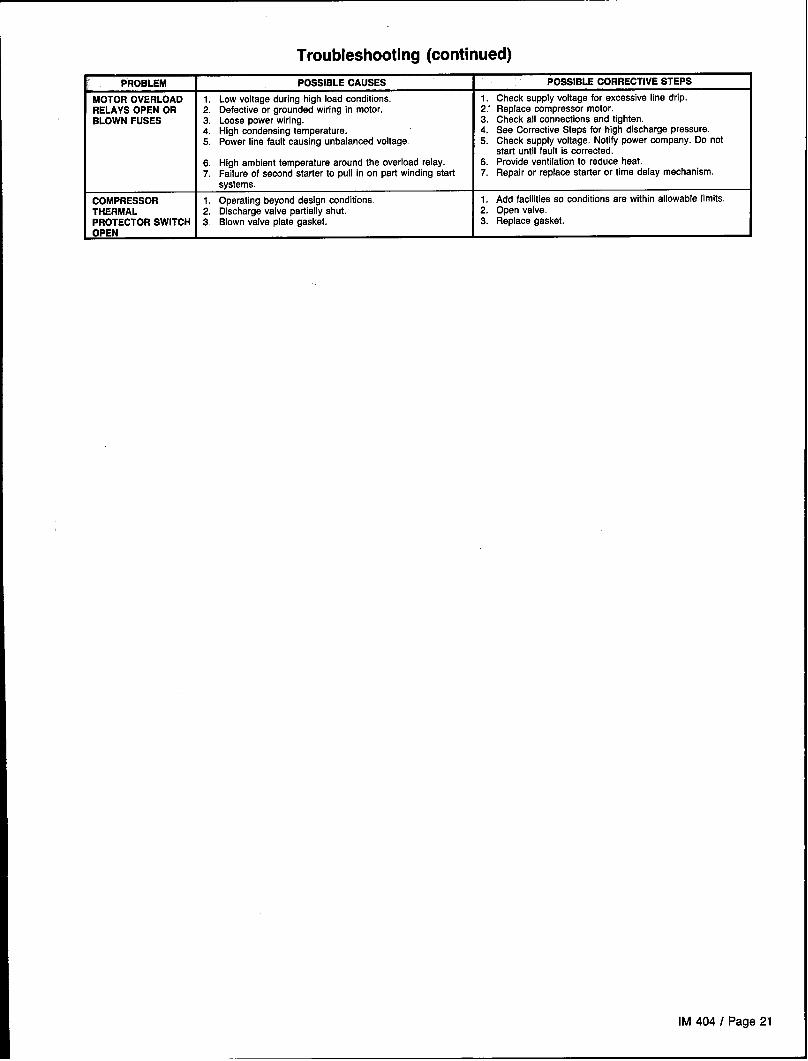
PROBLEM I POSSIBLE CAUSES I POSSIBLE CORRECTIVE STEPS
MOTOR OVERLOAD 1. Low voltage during high Ioad conditions.RELAYS OPEN OR
1. Check supplyvoltage forexcessive line dfip.2. Defectiveorgrounded wiring in motor.
BLOWN FUSES2.” Replace compressormotor.
3. Loosepowerwiring. 3. Check allconnections and tighten.4. High condensingtemperature. 4. See CorrectiveSteps forhigh dischargepressure.5. Power line fault causing unbalancedvoltage. 5. Chackaupply voltage. Notifypower company.Do not
start until fault is corrected.6. High ambienttemperaturearoundthe overloadrelay. 6. Provideventilationto reduce heat.7. Failure ofsecond starter topullin onpartwinding star'f 7. Repair orreplace starter ortime delay mechanism.
systems.
COMPRESSOR 1. Operating beyonddesign conditions.THERMAL
1. Add facilitiessoconditions arewithin allowablaflmits.2. Dischargevalve partiallyshut. 2. Open valve.
PROTECTOR SWITCH 3. Blownvalve plate gasket.OPEN
3. Replace gasket.
lM404/Page21

Product WarrantySnyderGeneral Corporation, hereinafter referred to as the“Company;’ warrants that it will provide, at the Company’soption, either free replacement parts or free repair of com-ponent parts in the event of any product manufactured by theCompany and used in the United States proves defective inmaterial or workmanship within twelve (12) months from in-itial start-up or eighteen (18) months from the date shippedby the Company, whichever comes first. For additional con-sideration, the Company warrants that for four (4) years follow-ing the initial warranty period it will provide, at the Company’soption, free replacement parts for the motor-compressor whichproves defective in material or workmanship. For an additionalconsideration, the Company warrants that for nine (9) yearsfollowing the initial warranty period it will provide free replace-ment of the heat exchanger in gas-fired or oil-fired furnaceswhich proves defective in material and workmanship. (Extend-ed warranties for motor-compressors and heat exchangersare not applicable unless separately purchased.)
To obtain assistance under this parts warranty, extendedmotor-compressor warranty, or extended heat exchanger war-ranty, simply contact the selling agency. To obtain informa-tion or to gain factory help for McQuay, Barry Blower andJennFan brandnames, contact SnyderGeneral Corporation,Warranty Claims Department, PO. Box 1551, Minneapolis, MN55440; telephone (612) 553-5330.
This warranty constitutes the buyer’s sole remedy. It isgiven in lieu of all other warranties. There is no impliedwarranty of merchantability or fitness for a particular pur-pose. In no event and under no circumstances, shall the
Company be liable for incidental or consequential da-mages, whether the theory be breach of this or any otherwarranty, negligence or strict tort.
This parts warranty and the optional warranties extend onlyto the original user. Of course, abuse, misuse, or alterationof the product in any manner voids the Company’s warrantyobligation. Neither the parts or extended warranty obligatesthe Company to pay any labor or service costs for removingor replacing parts, or any shipping charges. Refrigerants,fluids, oils, and expendable items such as filters are notcovered by this warranty.
The extended warranties apply only to integral componentsof the motor-compressor or heat exchanger, not to refrigerantcontrols, electrical controls, or mechanical controls, or tofailures caused by failure of those controls.
Attached to this warranty is a requirement for equipmentcontaining motor-compressors and/or furnaces to report stati-up information. The registration form accompanying the pro-duct must be completed and returned to the Company withinten (10) days of original equipment start-up. If that is not done,the date of shipment shall be presumed to be the date of start-up and the warranty shall expire twelve (12) months from thatdate.
No person (including any agent, salesman, dealer, ordistributor) has authority to expand the Company’s obligationbeyond the terms of this express warranty, or to state that theperformance of the product is other than that published bythe Company.
Page 22 I IM 404