Self-cleaning and self-powered UV sensor for highly ...
27
Subscriber access provided by Uppsala universitetsbibliotek is published by the American Chemical Society. 1155 Sixteenth Street N.W., Washington, DC 20036 Published by American Chemical Society. Copyright © American Chemical Society. However, no copyright claim is made to original U.S. Government works, or works produced by employees of any Commonwealth realm Crown government in the course of their duties. Article Self-cleaning and self-powered UV sensor for highly reliable outdoor UV detection Qi Xu, Junjie Lou, Ruichao Zhang, Binbin Ma, Suo Bai, and Yong Qin ACS Appl. Electron. Mater., Just Accepted Manuscript • DOI: 10.1021/acsaelm.0c00215 • Publication Date (Web): 10 May 2020 Downloaded from pubs.acs.org on May 14, 2020 Just Accepted “Just Accepted” manuscripts have been peer-reviewed and accepted for publication. They are posted online prior to technical editing, formatting for publication and author proofing. The American Chemical Society provides “Just Accepted” as a service to the research community to expedite the dissemination of scientific material as soon as possible after acceptance. “Just Accepted” manuscripts appear in full in PDF format accompanied by an HTML abstract. “Just Accepted” manuscripts have been fully peer reviewed, but should not be considered the official version of record. They are citable by the Digital Object Identifier (DOI®). “Just Accepted” is an optional service offered to authors. Therefore, the “Just Accepted” Web site may not include all articles that will be published in the journal. After a manuscript is technically edited and formatted, it will be removed from the “Just Accepted” Web site and published as an ASAP article. Note that technical editing may introduce minor changes to the manuscript text and/or graphics which could affect content, and all legal disclaimers and ethical guidelines that apply to the journal pertain. ACS cannot be held responsible for errors or consequences arising from the use of information contained in these “Just Accepted” manuscripts.
Transcript of Self-cleaning and self-powered UV sensor for highly ...
Subscriber access provided by Uppsala universitetsbibliotek
is published by the American Chemical Society. 1155 Sixteenth Street N.W.,Washington, DC 20036Published by American Chemical Society. Copyright © American Chemical Society.However, no copyright claim is made to original U.S. Government works, or worksproduced by employees of any Commonwealth realm Crown government in thecourse of their duties.
Article
Self-cleaning and self-powered UV sensorfor highly reliable outdoor UV detection
Qi Xu, Junjie Lou, Ruichao Zhang, Binbin Ma, Suo Bai, and Yong QinACS Appl. Electron. Mater., Just Accepted Manuscript • DOI: 10.1021/acsaelm.0c00215 • Publication Date (Web): 10 May 2020
Downloaded from pubs.acs.org on May 14, 2020
Just Accepted
“Just Accepted” manuscripts have been peer-reviewed and accepted for publication. They are postedonline prior to technical editing, formatting for publication and author proofing. The American ChemicalSociety provides “Just Accepted” as a service to the research community to expedite the disseminationof scientific material as soon as possible after acceptance. “Just Accepted” manuscripts appear infull in PDF format accompanied by an HTML abstract. “Just Accepted” manuscripts have been fullypeer reviewed, but should not be considered the official version of record. They are citable by theDigital Object Identifier (DOI®). “Just Accepted” is an optional service offered to authors. Therefore,the “Just Accepted” Web site may not include all articles that will be published in the journal. Aftera manuscript is technically edited and formatted, it will be removed from the “Just Accepted” Website and published as an ASAP article. Note that technical editing may introduce minor changesto the manuscript text and/or graphics which could affect content, and all legal disclaimers andethical guidelines that apply to the journal pertain. ACS cannot be held responsible for errors orconsequences arising from the use of information contained in these “Just Accepted” manuscripts.
1
Self-cleaning and self-powered UV sensor for highly reliable outdoor UV detection
Qi Xua, Junjie Loub, Ruichao Zhangb, Binbin Mab, Suo Baib and Yong Qinb*
a School of Advanced Materials and Nanotechnology, Xidian University, Xi’an 710071, China
b Institute of Nanoscience and Nanotechnology, Lanzhou University, Lanzhou 730000, China
KEYWORDS: UV sensor, ZnO, nanogenerator, self-cleaning, self-powered
nanodevice
ABSTRACT: Improving the individual node’s reliability and long-time working ability
are important for the giant wireless sensor networks. In this paper, a kind of self-
cleaning and self-powered UV sensor (SSUS) with the ability to give the intensity value
of UV light and against the dust contamination was developed. To avoid the influence
of dust, the SSUS can realize a self-cleaning function by either wind/water. This
character makes the SSUS be a good UV sensor in real environment especially in dust
environment with high reliability. In addition, after the SSUS is calibrated by a few
parameters, it can give the UV intensity according to the SSUS’s output directly with a
deviation about 3% in a self-powered manner, even the output of SSUS is not linearly
dependent on UV intensity.
Page 1 of 26
ACS Paragon Plus Environment
ACS Applied Electronic Materials
123456789101112131415161718192021222324252627282930313233343536373839404142434445464748495051525354555657585960
2
INTRODUCTION
UV sensors have important applications in many areas such as water quality testing,
mineral inspection, ultraviolet communication, and flame detection.1-3 Wireless Sensor
Network (WSN)4 which born from the joint of sensor technology, microelectric
technology, wireless communication technology and embedded technology, can greatly
improve the UV sensors’ ability in acquiring information in above areas. The bottle
neck that restricts the development of WSN is the long power supply of individual node
in the WSN.5 Traditionally, the power of the individual node is supplied by batteries.
However, with the expansion of network scale and the increase of the number of nodes,
monitoring and replacing the depleted batteries is a great challenge.
Replacing power supplies from traditionally batteries with new power source
which can convert the ambient energy into electricity is a promising way to solve the
above challenge.4 Among these new power sources, piezoelectric nanogenerators
(PENGs)6-7 are very competitive. On one hand, compared with solar energy and thermal
energy, the mechanical energy is undoubtedly a kind of energy that is not limited by
time and region. On the other hand, compared with triboelectric nanogenerators
(TENGs)8 which are also widely used to harvest the ambient mechanical energy9-11 and
UV sensing,12 the PENGs possess high mechanical endurance and durability13 without
the risk of material abrasion. With the increase of the output of the PENGs,14-19 it has
the more feasibility to be used to power the UV sensors. Xu showed a self-powered UV
Page 2 of 26
ACS Paragon Plus Environment
ACS Applied Electronic Materials
123456789101112131415161718192021222324252627282930313233343536373839404142434445464748495051525354555657585960
3
sensor constructed by a PENG and a ZnO nanowire-based UV sensor connected in
series, where the voltage drop across the sensor can be used to detect the UV light.20
Later, the self-powered UV sensors develop toward three directions. One direction
towards improving the PENG’s output to make the self-powered UV sensor’s signal
detection independent of high precision measurement or additional energy storage unit,
such as using large amount of aligned nanofibers with high piezoelectric coefficient to
improve the PENG’s integration degree,21 adopting single crystal ferroelectric
nanowire,22 utilizing the Maxwell–Wagner–Sillars (MWS) polarization in composite
piezoelectric material.23 Another direction towards developing wearable self-powered
UV sensor for real time personal health protection, such as weaving individual
piezoelectric active materials to form a two dimensional textile structure,24 improving
single piezoelectric fiber’s robustness,25 developing electronic skin.26-27 The final
research direction towards forming a compact structure, in which power unit and the
sensing unit is the same one, such as via the collective oscillation of embed metal
particles under UV light in the composite PENG to control the piezoelectric material’s
polarization state and thereby to control the PENG’s output.28
Albeit the rapid development of self-powered UV sensors, in order to make a
further step toward practical application of the self-powered UV sensors, there are two
points needed to be noticed. First, there doesn’t exist linear relationship between the
UV intensity and the self-powered sensor’s output. Although we have a few fixed UV
intensity points, how to determine the intensity of the UV light according to the output
of the self-powered UV sensors outside the tested points is unsolved. Second, as for the
Page 3 of 26
ACS Paragon Plus Environment
ACS Applied Electronic Materials
123456789101112131415161718192021222324252627282930313233343536373839404142434445464748495051525354555657585960
4
WSN containing many nodes, its practical working condition is usually in outdoor
environment and full of dust. The gradual degradation of the transmittance caused by
the accumulation of surrounding dust will decrease the penetrated light arrived on the
sensors,29 and thus make a large difficulty for accurately measure the UV intensity. So,
maintaining the node’s cleanness is critically important.
Here, we developed a self-cleaning and self-powered UV sensor (SSUS) which
can be used to reliably detect the UV intensities according to its output voltage in dust
environment. By applying a superhydrophobic coating, the accumulated dust on the
sensor can be cleaned easily by water or wind, and the voltage signal is only 0.3%/2.8%
larger than that of the original signal, which shows the sensor’s outstanding self-
cleaning ability. After the fitting parameters are determined according to the tested
points, the intensities (0.040 and 0.60 mW/cm2) of the UV light can be determined with
a deviation about 3%, even there doesn’t exist linear relationship between the UV
intensity and the SSUS’s output.
RESULTS AND DISCUSSION
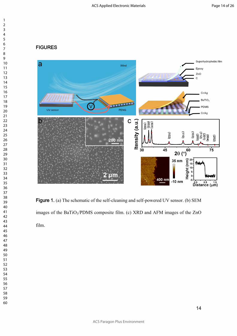
The structure of SSUS is schematically illustrated in Figure 1a, where a self-
cleaning UV sensor is in serial connected with a PENG and the output of the SSUS is
the voltage drop across the self-cleaning UV sensor. The PENG was fabricated by
dispersing BaTiO3 nanoparticles (Figure S1a) into the PDMS matrix with a mass ratio
of 40%. The nanoparticles are in tetragonal structure (Figure S1b) with lattice
parameters a and c equal to 4.02 Å and 4.04 Å, respectively. The piezoelectric
Page 4 of 26
ACS Paragon Plus Environment
ACS Applied Electronic Materials
123456789101112131415161718192021222324252627282930313233343536373839404142434445464748495051525354555657585960
5
coefficient d33 of BaTiO3 nanoparticles is 118 pC/N. In practice, the BaTiO3
nanoparticles are not spherical and periodically arranged in the composite film as the
schematic shows. Nevertheless, the BaTiO3 nanoparticles are dispersed evenly into the
matrix (Figure 1b), and this will contribute to the improvement of the PENG’s output.30
The thickness of the PDMS/BaTiO3 is about 40 μm. In order to increase the output
change of SSUS toward the intensity variation of UV light, an ultrathin hexagonal ZnO
film as shown in Figure 1c was used for fabricating UV sensor, as pointed by our
previous work31 this structure is superior for improving UV sensor’s response. In order
to improve the sensor’s stability against moisture32, a thin layer epoxy was used to
package the UV sensor.
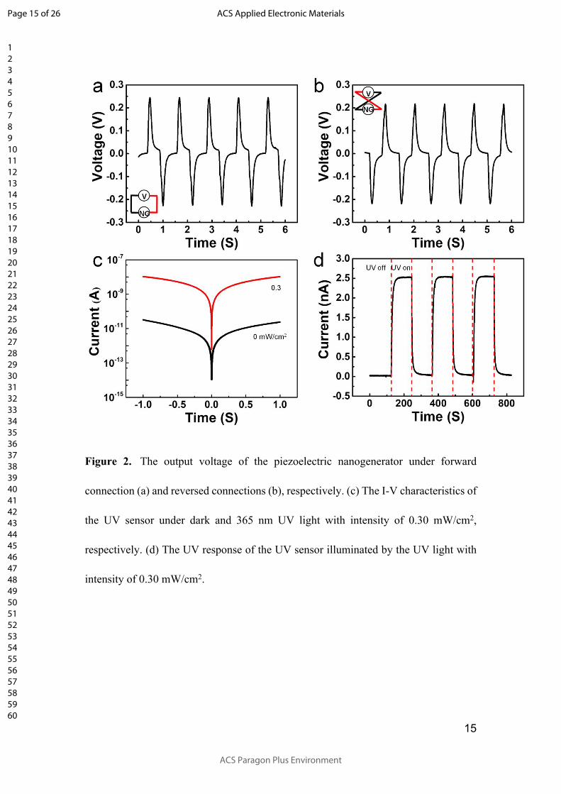
The performance of the PENG and UV sensor was characterized, respectively. By
periodically bending and releasing the PENG via a linear motor, the PENG with an area
of 15 cm2 shows a maximum peak output voltage of 0.25 V as shown in Figure 2a.
During the switching-polarity test in which the positive and negative probes of the
voltage meter are connected to the negative and positive ends of the PENG,
respectively, the output signal is reversed as shown in Figure 2b, and this confirmed
that the signal is the real signal not an artifact.7 Figure 2c shows the typical I-V curves
of the sensor in dark and under UV illumination with intensity of 0.30 mW/cm2 and
wavelength of 365 nm. The I-V curves in dark and UV illumination are both linear,
which indicates the carbon electrode forms an Ohmic contact with the ZnO film. Under
an UV intensity of 0.30 mW/cm2, the current reached a value of 10.4 nA at 1 V bias
voltage, in contrast to the dark current of 23.7 pA. The dynamic behavior of the UV
Page 5 of 26
ACS Paragon Plus Environment
ACS Applied Electronic Materials
123456789101112131415161718192021222324252627282930313233343536373839404142434445464748495051525354555657585960
6
sensor was characterized from the time-resolved photocurrent measurements by
alternatively exposing the sensor to UV light and dark as shown in Figure 2d. The
sensor’s rise and decay time, which are the time required for the current to increase to
90% of the steady-state photocurrent value and to decrease again by 90%, were also
characterized. The rise and decay time were 15.2 s and 10.6 s, respectively.
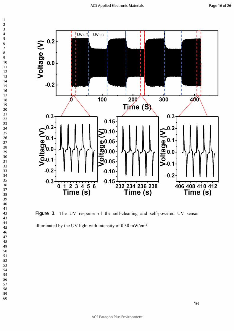
The dynamic behavior of the SSUS was characterized by alternatively exposing
the sensor to UV light of 0.30 mW/cm2 and dark as shown in Figure 3. In general,
either voltage signal or current signal can be used for UV detection. However,
as the impedance type of PENGs is capacitive33, the PENGs usually have a
large voltage but low current. In addition, the UV sensor’s resistance is also
large (42.2 GΩ in dark environment, derived from Figure 1c), the current in the
circuit will be reduced further. So, the voltage signal is chosen for UV detection
and we didn’t study the current change of the SSUS with the intensity of UV
light. In the test period, the performance of the SSUS is stable. As the output of the
SSUS is the voltage drop across the self-cleaning UV sensor, its value is sensitive to
the resistance of the UV sensor. Upon illuminated by the UV light, along with the
desorption of oxygen molecules from the ZnO film’s surface, the resistance of the UV
sensor decreased, and the output of the SSUS gradually changed from 0.23 V to 0.13
V. After turning off the UV light, along with the gradually adsorption of oxygen
molecules on the ZnO surface, the resistance of the UV sensor increased, and the output
of the SSUS gradually changed from 0.13 V to 0.23 V. The rise and decay time were
8.4 s and 10.9 s, respectively. Theoretically, the UV light can excite photogenerated
Page 6 of 26
ACS Paragon Plus Environment
ACS Applied Electronic Materials
123456789101112131415161718192021222324252627282930313233343536373839404142434445464748495051525354555657585960
7
carriers in BaTiO3, which will increase of conductance of BaTiO3 and lead to a reduced
impedance of the PENTG. However, the density of photogenerated carriers n is related
to the carrier lifetime τ,
(1)n dG
where, τ is the carrier lifetime, G is the carrier generation rate, which is equal to the
volume density of absorbed photons.34 The lifetime of photogenerated carriers in
BaTiO3 are too short (in < 60 ps)35 to generate appreciable generate appreciable carrier
density changes in BaTiO3. So, in practice, the influence of the UV on the PENG’s
impedance is negligible.
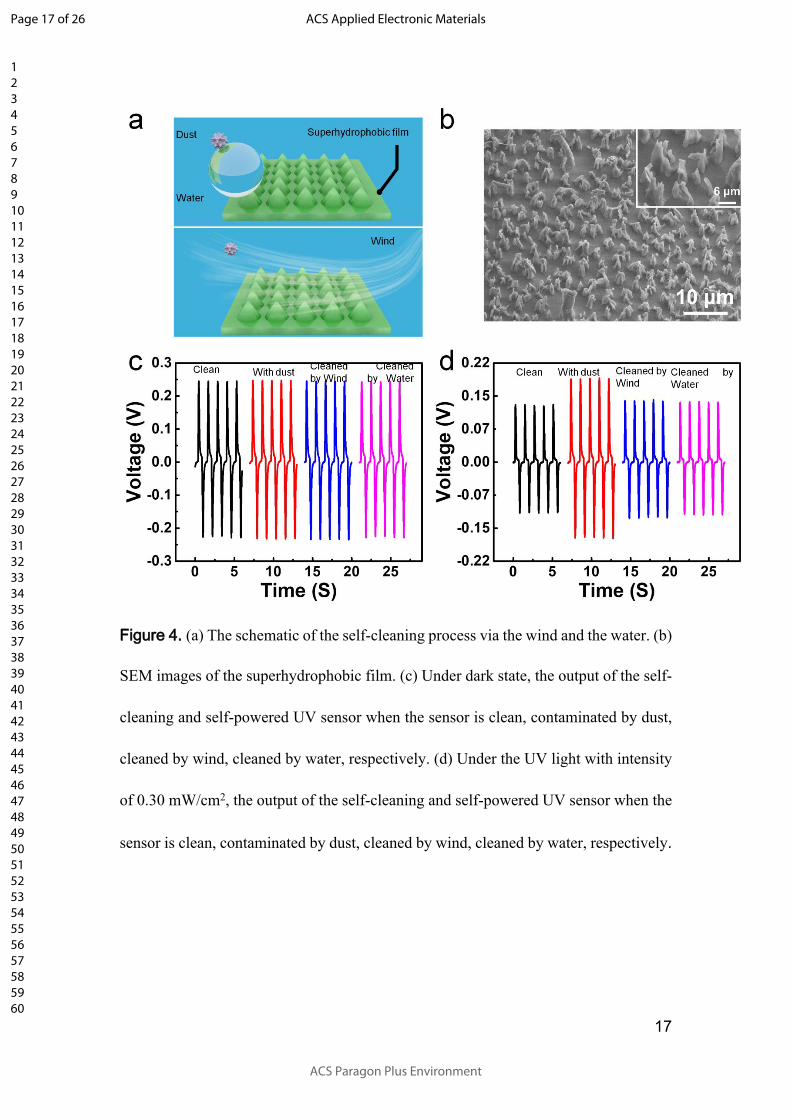
To solve the gradual degradation of the transmittance caused by the accumulation
of surrounding dust, a superhydrophobic film with a contact angle of 155° (Figure S2)
was used. The superhydrophobic coating is not an ordinary optically actively layer. The
superhydrophobic coating can keep the UV sensor clean, as the accumulated dust on
the sensor can be cleaned easily by water, especially by weak wind as schematically
shown in Figure 4a, which means our sensor can keep clean even in an environment
without water. The detailed structure of the superhydrophobic surface is shown in
Figure 4b. The surface of the superhydrophobic film is rough and full of uniformly
distributed hump composed of cone shaped structures. The cone shaped structures with
narrow tips and humps construct the superhydrophobic film’s hierarchical structure.
Packaged with this special film, the self-powered UV sensor (Figure S3a)
simultaneously has the self-cleaning property. Under dark environment, as the UV
Page 7 of 26
ACS Paragon Plus Environment
ACS Applied Electronic Materials
123456789101112131415161718192021222324252627282930313233343536373839404142434445464748495051525354555657585960
8
sensor is packaged, so the dust will not affect the resistance of the UV sensor, and the
output of the SSUS is not affected by the dust as shown in Figure 4c. Under UV
illumination with intensity of 0.30 mW/cm2, the dust will either shield or scatter the
UV light, so the output of the SSUS will be affected by the dust as shown in Figure 4d.
Upon sprinkling dust on the UV sensor (Figure S3b), due to the reduced penetrated UV
light, the output of the SSUS changes from the initial value of 0.130 V to 0.189 V,
which increases 45.4%. The reason is that the reduced penetrated will cause the
resistance of the UV sensor larger than that of the original clean state. After the dust
was cleaned by the wind generated by periodically squeezing a 5 mL plastic (Figure
S3c), the output of the SSUS decreased to 0.139 V, which is 6.2% larger than that of
the clean state. When the dust is further cleaned by the water (Figure S3d), the output
of the SSUS decreased to 0.135 V, which is 3.9% larger than that of the clean state.
These results show the SSUS has a good anti-dust property. This character makes the
SSUS be a good UV sensor in real environment especially in dust environment with
high reliability.
Finally, the self-powered UV sensor’s output under different UV intensities was
tested as shown in Figure 5a. As the UV intensity increases, the output of the SSUS
decreased in a nonlinear way. There does not exist a simple way to relate these data. In
order to obtain the value of the UV intensity from the output of SSUS outside the tested
data, the relationship between these tested data is needed. To do this, analysis based on
the equivalent circuit as shown in the inset of Figure 5a was conducted. The PENG is
considered as a voltage source V generated by the piezoelectric potential and a capacitor
Page 8 of 26
ACS Paragon Plus Environment
ACS Applied Electronic Materials
123456789101112131415161718192021222324252627282930313233343536373839404142434445464748495051525354555657585960
9
C of the PENG connected in serials,36 and the UV sensor is considered as a
photoresistor G(P), where G is the conductance of the photoresistor, P is the intensity
of the UV light. The output of the PENG can be approximated with a high accuracy
as37
V=d*f/C (2)
, where d is the piezoelectric constant of the PENG, f is the force exerted on the PENG.
As for circuit analysis, the output of PENG is simplified as a sinusoidal voltage source.
As only the frequency corresponding to the external driving frequency dominates, so
using the sinusoidal voltage source for circuit analysis is effective. From the equivalent
circuit, we can see that the voltage drop across the UV sensor is:
(3) 2
2 2
1
1
dfV PC G P
C
, where ω is the angular frequency of the external force. According to equation (3), in
order relate V with P, the relationship between G and P is needed. The I-V
characteristics of the UV sensor under UV light with different intensities is tested as
shown in Figure 5b. The obtained conductance of UV sensor under different UV
intensities is shown in Figure 5c. Their relationship obeys the power law G(P)=G0Pn,
which is caused by the complex process of electron-hole generation, trapping, and
recombination within the semiconductor.36 Combing with the equations of (2) and (3),
a fitting equation as follows can be used to relate V with P.
Page 9 of 26
ACS Paragon Plus Environment
ACS Applied Electronic Materials
123456789101112131415161718192021222324252627282930313233343536373839404142434445464748495051525354555657585960
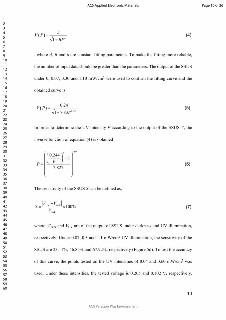
10
(4) 1 n
AV PBP
, where A, B and n are constant fitting parameters. To make the fitting more reliable,
the number of input data should be greater than the parameters. The output of the SSUS
under 0, 0.07, 0.30 and 1.10 mW/cm2 were used to confirm the fitting curve and the
obtained curve is
(5) 0.92
0.241 7.83
V PP
In order to determine the UV intensity P according to the output of the SSUS V, the
inverse function of equation (4) is obtained
(6)
1.0920.244 1
7.827VP
The sensitivity of the SSUS S can be defined as,
(7)UV dark
dark
100%V V
SV
where, Vdark and VUV are of the output of SSUS under darkness and UV illumination,
respectively. Under 0.07, 0.3 and 1.1 mW/cm2 UV illumination, the sensitivity of the
SSUS are 23.11%, 46.85% and 67.92%, respectively (Figure 5d). To test the accuracy
of this curve, the points tested on the UV intensities of 0.04 and 0.60 mW/cm2 was
used. Under these intensities, the tested voltage is 0.205 and 0.102 V, respectively.
Page 10 of 26
ACS Paragon Plus Environment
ACS Applied Electronic Materials
123456789101112131415161718192021222324252627282930313233343536373839404142434445464748495051525354555657585960
11
Substituting these values into equation (6), the obtained UV intensities are 0.04, and
0.58 mW/cm2, and the deviation are 2.5%, and 3.3%, respectively.
CONCLUSION
In summary, a self-cleaning and self-powered UV sensor (SSUS) composed of
PENG and a UV sensor was developed. When contaminated by dust, the SSUS can be
cleaned by either wind/water, and after the cleaning process, the output of the SSUS
has a deviation about 6.2%/ 3.9%, which shows a good self-cleaning ability. After
analyzing the equivalent circuit of the SSUS and the conductance of the UV sensor
versus the intensity of UV light, a fitting curve was given to predict the intensity of UV
light according to the output of the SSUS. When the fitting parameters are determined,
the intensities (0.040 and 0.60 mW/cm2) of the UV light can be determined with a
deviation about 3%, even there doesn’t exist linear relationship between the UV
intensity and the SSUS’s output.
EXPERIMENTAL SECTION
Preparation of the PENG
Firstly, the polydimethylsiloxane (PDMS; Dow Corning Corp.) solution was
prepared by adding curing agent into the base with a weight ratio of 1:10. Then, the
BaTiO3 nanoparticles (Aladdin, 99.99%, <100 nm) was dispersed into the PDMS with
a mass ratio of 40% by ultrasonic wave. Then, the mixture was placed into the in
vacuum condition (5 Pa) for 10 min. After the removal of air bubbles those were formed
Page 11 of 26
ACS Paragon Plus Environment
ACS Applied Electronic Materials
123456789101112131415161718192021222324252627282930313233343536373839404142434445464748495051525354555657585960
12
during ultrasonic wave, the mixture was spin coated onto an Cr/Ag electrode (3×5 cm)
with a spinning rate of 3000 rpm for 30 s and then cured at 80 °C for 30 min to solidify
the mixture. Next, the upper Cr/Ag electrode was sputtered. Interconnections were
made using copper wires and carbon paste. Then the device was poled under an electric
filed about 10 V/μm on the 120 ℃ hot plate for 2h.
To characterize the piezoelectric coefficient of BaTiO3 nanoparticles, they are
milled and pressed into a BaTiO3 plate with a relatively high density under 220 MPa
pressure, then sintered at 1200 ℃ for 3 h. The coefficient d33 is characterized on Quasi
Static Piezoelectric D33 Meter (ZJ-6A).
Preparation of the self-cleaning UV sensors
Firstly, 0.15 M ammine-hydroxo zinc precursor solution was spun onto the cleaned
glass substrate at 1000 rpm for 30 s, followed by a thermal annealing at 150 ºC for 2 h
in air; then, carbon interdigital electrode with electrode spacing of 500 μm was screen
printed on the ZnO film to form a UV sensor,31 followed by the epoxy resin
encapsulation. Finally, a superhydrophobic PDMS coating fabricated by a two-step
reactive ion etching process38 was covered on the UV sensor to form the final self-
cleaning UV sensor.
The XRD pattern of ZnO was obtained from a film fabricated by drop coating
method, where consecutive drops of the solution were deposited on the
Page 12 of 26
ACS Paragon Plus Environment
ACS Applied Electronic Materials
123456789101112131415161718192021222324252627282930313233343536373839404142434445464748495051525354555657585960
13
substate followed by thermal annealing at 150 ºC for 2 h in air, as the ZnO film
fabricated by spin coating method was too thin to hardly obtain detectable signals.
Test method
The dark current and photoresponse of the self-cleaning UV sensor were performed
using DS345 30 MHz synthesized function generator and SR 570 low-noise current
preamplifier (Figure S4a). The DS345 30 MHz Synthesized Function Generator are
capable of producing various patterns (sin, square, triangle, ramp) of voltage at a variety
of frequencies (1 µHz to 30.2 MHz) and amplitudes (0.01 V to 10 V). The UV light
intensity was quantified by a UV detector (Photoelectric Instrument Factory of Beijing
Normal University, UV-A). The voltage from the self-cleaning and self-powered UV
sensor under repeated bending and releasing driven by a LinMot linear motor (E1100)
was measured (Figure S4b) by SR560 low-noise voltage preamplifier.
Page 13 of 26
ACS Paragon Plus Environment
ACS Applied Electronic Materials
123456789101112131415161718192021222324252627282930313233343536373839404142434445464748495051525354555657585960
14
FIGURES
Figure 1. (a) The schematic of the self-cleaning and self-powered UV sensor. (b) SEM
images of the BaTiO3/PDMS composite film. (c) XRD and AFM images of the ZnO
film.
Page 14 of 26
ACS Paragon Plus Environment
ACS Applied Electronic Materials
123456789101112131415161718192021222324252627282930313233343536373839404142434445464748495051525354555657585960
15
Figure 2. The output voltage of the piezoelectric nanogenerator under forward
connection (a) and reversed connections (b), respectively. (c) The I-V characteristics of
the UV sensor under dark and 365 nm UV light with intensity of 0.30 mW/cm2,
respectively. (d) The UV response of the UV sensor illuminated by the UV light with
intensity of 0.30 mW/cm2.
Page 15 of 26
ACS Paragon Plus Environment
ACS Applied Electronic Materials
123456789101112131415161718192021222324252627282930313233343536373839404142434445464748495051525354555657585960
16
Figure 3. The UV response of the self-cleaning and self-powered UV sensor
illuminated by the UV light with intensity of 0.30 mW/cm2.
Page 16 of 26
ACS Paragon Plus Environment
ACS Applied Electronic Materials
123456789101112131415161718192021222324252627282930313233343536373839404142434445464748495051525354555657585960
17
Figure 4. (a) The schematic of the self-cleaning process via the wind and the water. (b)
SEM images of the superhydrophobic film. (c) Under dark state, the output of the self-
cleaning and self-powered UV sensor when the sensor is clean, contaminated by dust,
cleaned by wind, cleaned by water, respectively. (d) Under the UV light with intensity
of 0.30 mW/cm2, the output of the self-cleaning and self-powered UV sensor when the
sensor is clean, contaminated by dust, cleaned by wind, cleaned by water, respectively.
Page 17 of 26
ACS Paragon Plus Environment
ACS Applied Electronic Materials
123456789101112131415161718192021222324252627282930313233343536373839404142434445464748495051525354555657585960

18
Figure 5. (a) The output of the self-cleaning and self-powered UV sensor under
different UV intensities ranging from 0 to 1.10 mW/cm2, respectively. The insert is the
equivalent circuit of the self-cleaning and self-powered UV sensor. The I-V
characteristics (b) and the deduced conductance (c) of the UV sensor under different
UV intensities ranging from 0 to 1.10 mW/cm2, respectively. (d) The relationship
between the peak of the output of the self-cleaning and self-powered UV sensor under
different UV intensities. The squares represent experimental data; the red curve is the
fitted curve.
Page 18 of 26
ACS Paragon Plus Environment
ACS Applied Electronic Materials
123456789101112131415161718192021222324252627282930313233343536373839404142434445464748495051525354555657585960
19
AUTHOR INFORMATION
Corresponding Author
E-mail: [email protected]
Author Contributions
The manuscript was written through contributions of all authors. All authors
have given approval to the final version of the manuscript.
ACKNOWLEDGMENT
We sincerely acknowledge the support from Joint fund of Equipment pre-Research and
Ministry of Education (No. 6141A02022518), the National Program for Support of
Top-notch Young Professionals, and the Fundamental Research Funds for the Central
Universities (No. lzujbky-2018-ot04), NSFC (No. 81702095), The Project Supported
by Natural Science Basic Research Plan in Shaanxi Province of China (2019JQ-652).
SUPPORTING INFORMATION
The Supporting Information is available free of charge via the Internet at
http://pubs.acs.org/.
Figures about the SEM image, XRD spectrum (Figure S1); Photographs of a water
droplet on the superhyndrophobic surface (Figure S2); Optical images of SSUS (Figure
S3); Schematics about the measurements (Figure S4).
Page 19 of 26
ACS Paragon Plus Environment
ACS Applied Electronic Materials
123456789101112131415161718192021222324252627282930313233343536373839404142434445464748495051525354555657585960
20
REFERENCES
(1) Monroy, E.; Calle, F.; Pau, J. L.; Munoz, E.; Omnes, F.; Beaumont, B.; Gibart, P.
AlGaN-based UV photodetectors. J. Cryst. Growth 2001, 230 (3-4), 537-543.
(2) Yu, A. G. Semiconductor near-ultraviolet photoelectronics. Semicond. Sci. Technol.
1999, 14 (7), R41.
(3) Razeghi, M.; Rogalski, A. Semiconductor ultraviolet detectors. J. Appl. Phys. 1996,
79 (10), 7433-7473.
(4) Akyildiz, I. F.; Kasimoglu, I. H. Wireless sensor and actuators networks: research
challenges. Ad Hoc Networks 2004, 2 (4), 351-367.
(5) Watral, Z.; Michalski, A. Selected problems of power sources for wireless sensors
networks [instrumentation notes]. IEEE Instrum. Meas. Mag. 2013, 16 (1), 37-43.
(6) Wang, Z. L.; Song, J. H. Piezoelectric nanogenerators based on zinc oxide nanowire
arrays. Science 2006, 312 (5771), 242-246.
(7) Yang, R. S.; Qin, Y.; Li, C.; Dai, L. M.; Wang, Z. L. Characteristics of output
voltage and current of integrated nanogenerators. Appl. Phys. Lett. 2009, 94 (2),
022905.
(8) Fan, F. R.; Tian, Z. Q.; Wang, Z. L. Flexible triboelectric generator! Nano Energy
2012, 1 (2), 328-334.
(9) Zhu, G.; Zhou, Y. S.; Bai, P.; Meng, X. S.; Jing, Q.; Chen, J.; Wang, Z. L. A Shape-
Adaptive Thin-Film-Based Approach for 50% High-Efficiency Energy Generation
Through Micro-Grating Sliding Electrification. Adv. Mater. 2014, 26 (23), 3788-3796.
Page 20 of 26
ACS Paragon Plus Environment
ACS Applied Electronic Materials
123456789101112131415161718192021222324252627282930313233343536373839404142434445464748495051525354555657585960
21
(10) Ahmed, A.; Saadatnia, Z.; Hassan, I.; Zi, Y.; Xi, Y.; He, X.; Zu, J.; Wang, Z. L.
Self-Powered Wireless Sensor Node Enabled by a Duck-Shaped Triboelectric
Nanogenerator for Harvesting Water Wave Energy. Adv. Energy Mater. 2017, 7 (7),
1601705.
(11) Li, S.; Peng, W.; Wang, J.; Lin, L.; Zi, Y.; Zhang, G.; Wang, Z. L. All-Elastomer-
Based Triboelectric Nanogenerator as a Keyboard Cover To Harvest Typing Energy.
ACS Nano 2016, 10 (8), 7973-7981.
(12) Dai, Y.; Fu, Y.; Zeng, H.; Xing, L.; Zhang, Y.; Zhan, Y.; Xue, X. A Self-Powered
Brain-Linked Vision Electronic-Skin Based on Triboelectric-Photodetecing Pixel-
Addressable Matrix for Visual-Image Recognition and Behavior Intervention. Adv.
Funct. Mater. 2018, 28 (20), 1800275.
(13) Siddiqui, S.; Kim, D.-I.; Roh, E.; Duy, L. T.; Trung, T. Q.; Nguyen, M. T.; Lee,
N.-E. A durable and stable piezoelectric nanogenerator with nanocomposite nanofibers
embedded in an elastomer under high loading for a self-powered sensor system. Nano
Energy 2016, 30, 434-442.
(14) Yang, R.; Qin, Y.; Dai, L.; Wang, Z. L. Power generation with laterally packaged
piezoelectric fine wires. Nat. Nanotechnol. 2009, 4 (1), 34-39.
(15) Zhu, G.; Yang, R.; Wang, S.; Wang, Z. L. Flexible High-Output Nanogenerator
Based on Lateral ZnO Nanowire Array. Nano Lett. 2010, 10 (8), 3151-3155.
(16) Hu, Y.; Lin, L.; Zhang, Y.; Wang, Z. L. Replacing a Battery by a Nanogenerator
with 20 V Output. Adv. Mater. 2012, 24 (1), 110-114.
Page 21 of 26
ACS Paragon Plus Environment
ACS Applied Electronic Materials
123456789101112131415161718192021222324252627282930313233343536373839404142434445464748495051525354555657585960
22
(17) Zhu, G.; Wang, A. C.; Liu, Y.; Zhou, Y. S.; Wang, Z. L. Functional Electrical
Stimulation by Nanogenerator with 58 V Output Voltage. Nano Lett. 2012, 12 (6),
3086-3090.
(18) Gu, L.; Cui, N.; Cheng, L.; Xu, Q.; Bai, S.; Yuan, M.; Wu, W.; Liu, J.; Zhao, Y.;
Ma, F.; Qin, Y.; Wang, Z. L. Flexible Fiber Nanogenerator with 209 V Output Voltage
Directly Powers a Light-Emitting Diode. Nano Lett. 2013, 13 (1), 91-94.
(19) Yeo, H. G.; Ma, X.; Rahn, C.; Trolier-McKinstry, S. Efficient Piezoelectric Energy
Harvesters Utilizing (001) Textured Bimorph PZT Films on Flexible Metal Foils. Adv.
Funct. Mater. 2016, 5940-5946.
(20) Xu, S.; Qin, Y.; Xu, C.; Wei, Y.; Yang, R.; Wang, Z. L. Self-powered nanowire
devices. Nat. Nanotechnol. 2010, 5 (5), 366-373.
(21) Wu, W.; Bai, S.; Yuan, M.; Qin, Y.; Wang, Z. L.; Jing, T. Lead Zirconate Titanate
Nanowire Textile Nanogenerator for Wearable Energy-Harvesting and Self-Powered
Devices. Acs Nano 2012, 6 (7), 6231-6235.
(22) Bai, S.; Xu, Q.; Gu, L.; Ma, F.; Qin, Y.; Wang, Z. L. Single crystalline lead
zirconate titanate (PZT) nano/micro-wire based self-powered UV sensor. Nano Energy
2012, 1 (6), 789-795.
(23) Saravanakumar, B.; Thiyagarajan, K.; Alluri, N. R.; SoYoon, S.; Taehyun, K.; Lin,
Z.-H.; Kim, S.-J. Fabrication of an eco-friendly composite nanogenerator for self-
powered photosensor applications. Carbon 2015, 84, 56-65.
(24) Bai, S.; Zhang, L.; Xu, Q.; Zheng, Y.; Qin, Y.; Wang, Z. L. Two dimensional
woven nanogenerator. Nano Energy 2013, 2 (5), 749-753.
Page 22 of 26
ACS Paragon Plus Environment
ACS Applied Electronic Materials
123456789101112131415161718192021222324252627282930313233343536373839404142434445464748495051525354555657585960
23
(25) Zhang, L.; Bai, S.; Su, C.; Zheng, Y.; Qin, Y.; Xu, C.; Wang, Z. L. A High-
Reliability Kevlar Fiber-ZnO Nanowires Hybrid Nanogenerator and its Application on
Self-Powered UV Detection. Adv. Funct. Mater. 2015, 25 (36), 5794-5798.
(26) Han, W.; Zhang, L.; He, H.; Liu, H.; Xing, L.; Xue, X. Self-powered vision
electronic-skin basing on piezo-photodetecting Ppy/PVDF pixel-patterned matrix for
mimicking vision. Nanotechnology 2018, 29 (25), 255501.
(27) Zhang, L.; Fu, Y.; Xing, L.; Liu, B.; Zhang, Y.; Xue, X. A self-powered flexible
vision electronic-skin for image recognition based on a pixel-addressable matrix of
piezophototronic ZnO nanowire arrays. Journal of Materials Chemistry C 2017, 5 (24),
6005-6013.
(28) Sinha, T. K.; Ghosh, S. K.; Maiti, R.; Jana, S.; Adhikari, B.; Mandal, D.; Ray, S.
K. Graphene-Silver-Induced Self-Polarized PVDF-Based Flexible Plasmonic
Nanogenerator Toward the Realization for New Class of Self Powered Optical Sensor.
ACS Appl. Mater. Interfaces 2016, 8 (24), 14986-14993.
(29) Khonkar, H.; Alyahya, A.; Aljuwaied, M.; Halawani, M.; Al Saferan, A.; Al-
Khaldi, F.; Alhadlaq, F.; Wacaser, B. A. Importance of cleaning concentrated
photovoltaic arrays in a desert environment. Solar Energy 2014, 110, 268-275.
(30) Park, K.-I.; Lee, M.; Liu, Y.; Moon, S.; Hwang, G.-T.; Zhu, G.; Kim, J. E.; Kim,
S. O.; Kim, D. K.; Wang, Z. L.; Lee, K. J. Flexible Nanocomposite Generator Made of
BaTiO3 Nanoparticles and Graphitic Carbons. Adv. Mater. 2012, 24 (22), 2999-3004.
Page 23 of 26
ACS Paragon Plus Environment
ACS Applied Electronic Materials
123456789101112131415161718192021222324252627282930313233343536373839404142434445464748495051525354555657585960
24
(31) Xu, Q.; Cheng, L.; Meng, L.; Wang, Z.; Bai, S.; Tian, X.; Jia, X.; Qin, Y. Flexible
Self-Powered ZnO Film UV Sensor with a High Response. ACS Appl. Mater. Interfaces
2019, 11 (29), 26127-26133.
(32) Li, Y.; Della Valle, F.; Simonnet, M.; Yamada, I.; Delaunay, J.-J. Competitive
surface effects of oxygen and water on UV photoresponse of ZnO nanowires. Appl.
Phys. Lett. 2009, 94 (2), 023110.
(33) Wang, Z. L. On Maxwell's displacement current for energy and sensors: the origin
of nanogenerators. Mater. Today 2017, 20 (2), 74-82.
(34) Halsall, M. P.; Crowe, I. F.; Mullins, J.; Oliver, R. A.; Kappers, M. J.; Humphreys,
C. J. Photomodulated Reflectivity Measurement of Free-Carrier Dynamics in
InGaN/GaN Quantum Wells. ACS Photonics 2018, 5 (11), 4437-4446.
(35) Peixian Ye, A. B., Christian Demers, Marguerite-Marie Denariez Roberge, and
Xing Wu. Picosecond photoinduced absorption in photorefractive BaTiO3. Opt. Lett.
1991, 16 (13), 980-982.
(36) Zhou, Y.; Liu, W.; Huang, X.; Zhang, A.; Zhang, Y.; Wang, Z. L. Theoretical
study on two-dimensional MoS2 piezoelectric nanogenerators. Nano Res. 2016, 9 (3),
800-807.
(37) Xu, Q.; Qin, Y. Theoretical study of enhancing the piezoelectric nanogenerator’s
output power by optimizing the external force’s shape. APL Mater. 2017, 5 (7), 074101.
(38) Xu, Q.; Zhao, Q.; Zhu, X.; Cheng, L.; Bai, S.; Wang, Z.; Meng, L.; Qin, Y. A new
kind of transparent and self-cleaning film for solar cells. Nanoscale 2016, 8 (41),
17747-17751.
Page 24 of 26
ACS Paragon Plus Environment
ACS Applied Electronic Materials
123456789101112131415161718192021222324252627282930313233343536373839404142434445464748495051525354555657585960
25
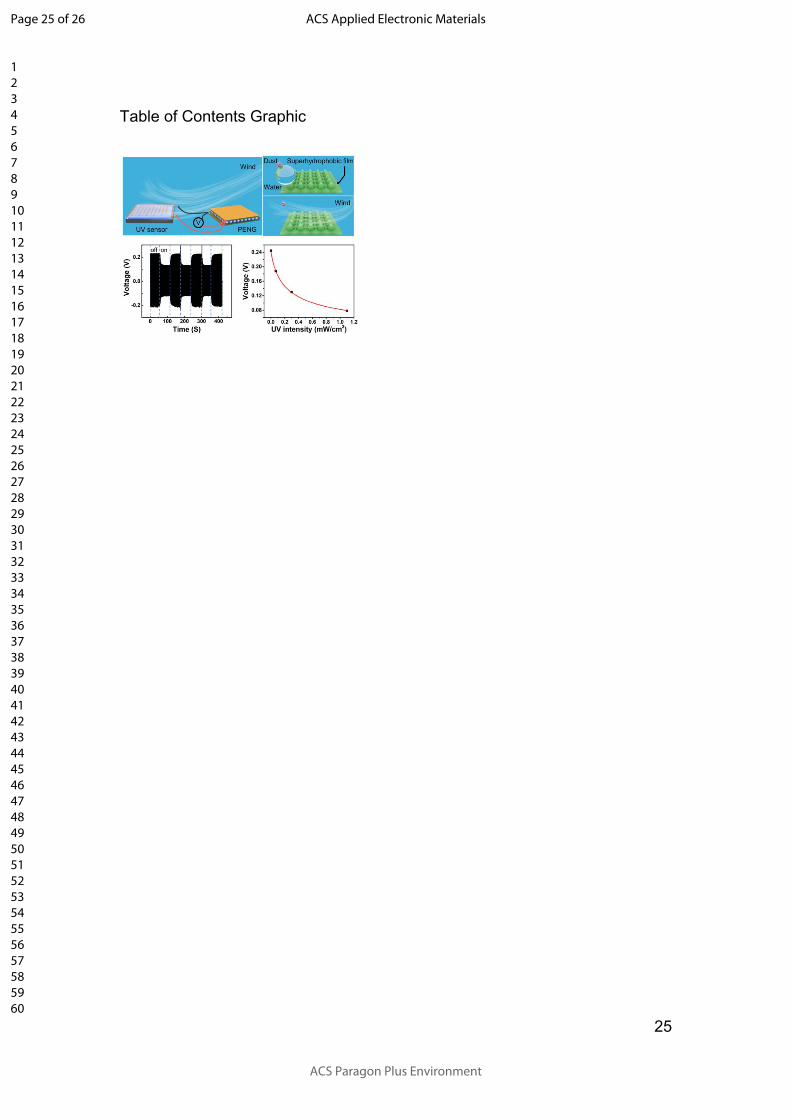
Table of Contents Graphic
Page 25 of 26
ACS Paragon Plus Environment
ACS Applied Electronic Materials
123456789101112131415161718192021222324252627282930313233343536373839404142434445464748495051525354555657585960
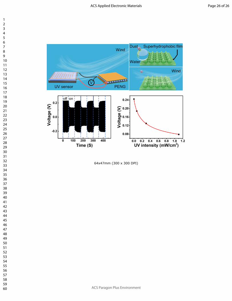
64x47mm (300 x 300 DPI)
Page 26 of 26
ACS Paragon Plus Environment
ACS Applied Electronic Materials
123456789101112131415161718192021222324252627282930313233343536373839404142434445464748495051525354555657585960