Self-applied Magnetic Field Intensity Effects on Solid...
11
* Copyright © 20001 by Giorgio Paccani and Luigi Petrucci. Published by the Electric Rocket Propulsion Society with permission. Self-applied Magnetic Field Intensity Effects on Solid Propellant Mpd Thruster Performance * Luigi Petrucci and Giorgio Paccani Università degli Studi di Roma “La Sapienza” Dipartimento Meccanica e Aeronautica, Via Eudossiana 18, 00184 Rome, Italy. Rome Italy +39.06.44585283 [email protected] IEPC-01-139 The effect on solid propellant MPD thruster behavior of different axial self-applied magnetic fields was investigated. The thrusters have coaxial electrodes with six radially-mounted propellant bars surrounding the cathode. The self-applied magnetic fields were respectively generated by a six- and a twelve-turn coil. Measurements included electrical characteristics, impulse bit (thrust stand), exhaust velocity (TOF Langmuir probe system), and ablated propellant mass per shot. Under constant current, higher self-applied magnetic fields lead to higher impedances, higher ablated mass, and higher impulse bit. However at constant energy per shot, the impulse bit gained by applying the magnetic field does not justify the energy lost to feed the coil. Nomenclature MPD Magnetoplasmadynamic PFN Pulse forming network PVC Polyvinyl chloride TOF Time of flight Symbols b Theoretical law coefficient, N/A 2 B Magnetic field, T C Capacitance, C E Energy, J f Volume force, N/m 3 F Thrust, N I b Impulse bit, N s i Current, A J Current density, A/m 3 K i 2 /m m Ablated mass per shot, Kg P Power, W r Radius t Time, s V Potential, V w Exhaust velocity, m/s Z Impedance, S 0 Efficiency J Discharge duration, s Q Current Parameter, I i 2 dt, A 2 s Subscripts Max Maximum r Radial component t Thrust T Thruster th Theoretical z Axial component 2 Azimuthal component 0 Initial or set value Introduction This paper deals with the effects of self-applied magnetic field intensity on working and performance parameters of coaxial solid propellant MPD thrusters (Fig. 1) operating in pulsed mode with instantaneous power levels of a few megawatts during pulses (shots) which last approximately one millisecond. In these electromagnetic thrusters the propellant mass flow rate is not an externally controllable variable; performance is
Transcript of Self-applied Magnetic Field Intensity Effects on Solid...
*Copyright © 20001 by Giorgio Paccani and Luigi Petrucci. Published by the Electric Rocket Propulsion Society with permission.
Self-applied Magnetic Field Intensity Effects on Solid
Propellant Mpd Thruster Performance*
Luigi Petrucci and Giorgio Paccani
Università degli Studi di Roma “La Sapienza”
Dipartimento Meccanica e Aeronautica,
Via Eudossiana 18, 00184 Rome, Italy.
Rome Italy
+39.06.44585283
IEPC-01-139
The effect on solid propellant MPD thruster behavior of different axial self-applied magnetic fields was
investigated. The thrusters have coaxial electrodes with six radially-mounted propellant bars surrounding the
cathode. The self-applied magnetic fields were respectively generated by a six- and a twelve-turn coil.
Measurements included electrical characteristics, impulse bit (thrust stand), exhaust velocity (TOF Langmuir
probe system), and ablated propellant mass per shot. Under constant current, higher self-applied magnetic
fields lead to higher impedances, higher ablated mass, and higher impulse bit. However at constant energy per
shot, the impulse bit gained by applying the magnetic field does not justify the energy lost to feed the coil.
Nomenclature
MPD Magnetoplasmadynamic
PFN Pulse forming network
PVC Polyvinyl chloride
TOF Time of flight
Symbols
b Theoretical law coefficient, N/A2
B Magnetic field, T
C Capacitance, C
E Energy, J
f Volume force, N/m3
F Thrust, N
Ib Impulse bit, N s
i Current, A
J Current density, A/m3
K i2/m
m Ablated mass per shot, Kg
P Power, W
r Radius
t Time, s
V Potential, V
w Exhaust velocity, m/s
Z Impedance, S
0 Efficiency
J Discharge duration , s
Q Current Parameter, I i2 dt, A2 s
Subscripts
Max Maximum
r Radial component
t Thrust
T Thruster
th Theoretical
z Axial component
2 Azimuthal component
0 Initial or set value
Introduction
This paper deals with the effects of self-applied magnetic
field intensity on working and performance parameters
of coaxial solid propellant MPD thrusters (Fig. 1)
operating in pulsed mode with instantaneous power
levels of a few megawatts during pulses (shots) which
last approximately one millisecond. In these
electromagnetic thrusters the propellant mass flow rate is
not an externally controllable variable; performance is
- 2 -
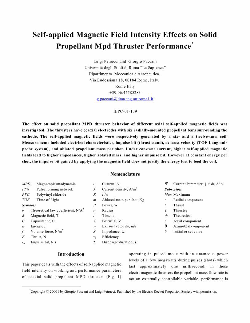
Figure 1 - MPD Discharge chamber with Self-applied
magnetic field.
(2)
(4)
(1)
(3)
determined by engine scale1, arc and propellant
properties2,3 ,4, arc-propellant interaction5,6 and engine
geometry7,8.
It is widely known that, in a stationary MPD thruster with
self-induced magnetic field, the thrust is a function of the
anode radius, ra, and cathode radius, rc, through the
relation9,
where,
The parameter “b” is the electromagnetic thrust
coefficient also called the Maecker law10 coefficient. In
a pulsed thruster, the relation becomes
where,
The Maecker law can be theoretically derived by a
simplified bidimensional treatment and is in good
agreement with experimental results8.
The presence of an applied axial magnetic field, which is
superimposed upon the self-induced one, modifies the
phenomena inside the acceleration duct, and hence
modifies the resulting thrust11-15.
The interaction between this external magnetic field and
the discharge causes a plasma swirling motion around the
thruster axis. The phenomena inside the thruster,
although still azimuthally symmetric, can no longer be
treated as bi-dimensional phenomena.
In previous studies16,17, the impact of a “self-applied”
magnetic field generated by coaxial coils, on the
behavior of coaxial ablative pulsed MPD thrusters has
been examined, while varying the discharge chamber
geometry, the anodic configuration, and the coils
configuration and axial position. The effects of the
magnetic field, due to a two-turn or six-turn coil crossed
by the same current creating the discharge, became more
important augmenting the discharge energy, i.e.
augmenting the magnitude of the magnetic field itself.
In this paper, the effects - at equal energy - on the
behavior of an ablative MPD thruster of the self-applied
magnetic field intensity will be examined. The magnetic
fields with different intensity were respectively generated
by a six- and a twelve-turn coil of equal length and
equally positioned with respect to the same discharge
chamber-anode-nozzle. Both coils surrounded 7/9 of the
acceleration duct length (starting from the cathode tip)
(see Fig. 1).
Experimental Setup
Thruster System
The MPD propulsive system consists of PFN (Pulse
Forming Network), transmission line, thruster (with or
without coil), start-up circuit.
- 3 -
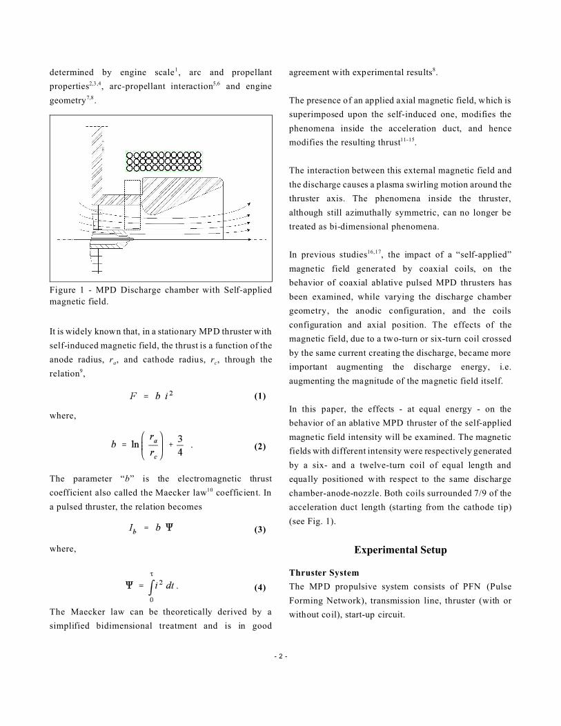
Figure 2 - Baseline MIRA solid propellant MPD thruster.
Figure 3 - A partial view of the twelve-turn coil mounted
on the thruster.
(5)
The baseline thruster configuration (MIRA) is shown in
Fig. 2 and is described in detail in previous works18,19. It
has a coaxial geometry with a conductive (aluminum-
silicon-manganese-alloy) converging-diverging discharge
chamber-anode-nozzle and a cylindrical-conical cathode
(copper). Six Teflon® propellant bars pass radially
through the wall of the nozzle and in a symmetrical
arrangement surround the cathode tip. A trigger electrode
(tungsten) protrudes from the cathode within which it is
co-axially located.
The two coils19 (Fig. 3) have a length of 72 mm; this
length was chosen in order to generate, inside the
acceleration duct, an almost purely axial magnetic field
(see Fig. 1). The coils consist of six copper cables - 2.5
mm2 in section - wound around a cylinder of PVC. At
the ends of the cylinder two 2.5 mm tick copper flanges
are mounted. Six brass conductors connect the coil to the
alimentation flange of the thruster (“in-going”
conductors), while a further six connect it to the
disc har ge chamber-anode-noz zle (“out-going”
conductors). The winding of each of the six cables can be
considered equivalent to six turns with a mean radius of
69 mm, or to twelve turns with a mean radius of 75 mm.
In the followings, the MIRA thruster with the six-turn
coil and the MIRA thruster with the twelve-turn coil are
respectively denoted MIRA_L06 and MIRA_L12.
The energy storage means consists of a capacitive Pulse
Forming Network (PFN) with a total capacitance of
0.072 ± 0.002 F coaxially connected to the thruster
electrodes. The PFN set voltage was the primary
externally controllable variable during the tests.
Measurements and Procedures
Experimental measurements included the instantaneous
electrical characteristics [PFN electrodes potential
difference V(t) and discharge current intensity i(t)],
impulse bit (Ib), ion velocity in the exhaust jet (w), and
ablated propellant mass per shot (m) for each thruster
configuration. The PFN provided input energies, E0,
from 1333 J in increments of 333 J. Maximum energy
value of 2333 and 3333 respectively were used for the
MIRA_L12 and the other two thrusters.
The PFN output energy was defined by setting the PFN
potential, V0, according to
The electrode potential was measured by an oscilloscope
while current was measured using a Rogowsky probe. A
value averaged over 12 measurements was used as the
standard value for each electrical parameter. The energy
per shot

- 4 -
Figure 4 - Current vs. time at input energy E0 = 2000 J
Figure 5 - Current versus time at input energy E0 = 2666
J for the MIRA_L12.
(6)
was computed using the measured electrical parameters.
The ablated propellant mass was obtained from the
difference in weight of the propellant bars before and
after each series of shots. The propellant bars were
weighed using an electronic balance. The error in this
measurement has been estimated to be a maximum of ±5
mg.
A thrust balance, described in detail elsewhere20, was
used to measure the thruster impulse bit based on an
average value from 12 measurements.
Finally, the ion velocity in the exhaust was measured
based on an average value from 30 TOF measurements
obtained from cross correlation of the signals from two
double Langmuir probes located downstream of the
thruster21.
Uncertainties were calculated using error propagation
theory based on the standard deviation of the individual
measurements.
The tests were conducted in a 0.5 m3, polyvinyl chloride
(PVC) vacuum tank with a nominal back pressure of 10-2
Pa. All of the instrumentation was housed in a full
Faraday cage and data acquisition was computer-
controlled.
Experimental Results
The electrical parameters of the different thrusters (with
and without coil) differed greatly, leading to very
different characteristic curves19: in Fig. 4 the current
intensity, i, during an impulse, in each thruster, is shown
as a function of the time at an input energy, E0, of 2000
J. The presence of the coil lowers the maximum value,
iMax, of the current intensity while increasing the pulse
duration. Augmenting the number of coils amplifies
these effects. Moreover at an input energy, E0, higher
than 2333 J, the propulsive system with the 12-turns coil
presents an “inversion” of the current (see Fig. 5), that
can damage the capacitors. For this reason the thruster
MIRA_L12 has not been tested with input energies
higher than E0=2333.
The differences between the characteristic curves of the
three prop ulsive sy stems (P FN +trans missio n
line+thruster), rend a comparison between the
characteristic parameters of the different propulsive

- 5 -
Figure 6 - Current parameter, Q , as a function of energy,
ET, shows a linear relationship.
Figure 7 - Thruster system impedance, Ze, versus current
parameter, Q , shows the tendency towards a lower
limiting constant value with increasing energy.
systems at equal input energy, E0, almost useless: the
influence of the coupling is greater than any other effect.
Current parameter
To analyze the behavior of the thrusters thoroughly, the
variation in the characteristic parameters with energy, ET,
and with the current parameter, Q , must be studied. Both
of these parameters show linear increases as a function of
input energy, E0. When cross-plotting the energy ET and
current parameter (Fig. 6), the behavior is strictly linear.
As expected, due to the coil impedance, this parameter
has the highest values in the MIRA thruster and decreases
while increasing the number of turns of the coil.
The energy ET accounts for the electrical losses in the
transmission lines and in the thruster (coil, electrodes,
discharge), while Q provides information on the only
phenomena which occur into the discharge chamber
regardless of electrical losses. In other words, graphs
reported as a function of the thruster energy, ET, account
for the functioning of the thruster+transmission line
system while the current parameter, Q , only account for
the behavior of the acceleration duct. The results will be
presented as a function of Q unless the use of ET
enables additional insights.
Impedance
The impedance of the (thruster+transmission line) system
exhibits similar behavior both as function of ET and Q ,
showing a parabolic decrease while tending towards a
limiting constant value (see Fig. 7).
For constant ET and Q , as can be expected from the
presence of the coils, the impedance characteristics obey
the following inequality:
ZMIRA_L12 > ZMIRA_L06 > ZMIRA.
Ablated mass
The ablated propellant mass per shot increases linearly
with increasing energy, ET, and current parameter, Q (see
Fig. 8). At constant Q , both in terms of absolute values
and slopes, the ablated mass characteristics obey the
following inequality:
mMIRA_L12 > mMIRA_L06 > mMIRA .

- 6 -
Figure 8 - The linear behavior of the ablated mass per
shot, m, as a function of current parameter, Q .
(7)
Figure 9 - The self-applied magnetic field changes the
behavior of the K parameter as a function of energy, ET.
Figure 10 - Ion exhaust velocity shows substantial data
scatter and a tendency to decrease with increasing Q .
K parameter
In the range of voltage over which the thruster exhibits its
best behavior, the baseline MIRA shows a parameter
generally constant while exhibiting small irregularities,
whilst the two thruster systems with the coil exhibit
decreasing values, tending at a constant at the higher
energies (Fig. 9).
With energy, ET, kept constant, at the lower energies,
MIRA_L12 shows the highest values. On increasing the
energy, the difference between MIRA_L06 and
MIRA_L12 decreases, until, at the highest energies, the
differnce becomes negligible. Moreover at such energies,
the baseline MIRA shows the highest values.
Jet Exhaust Velocity
The axial ion velocity, shows a general trend towards
decreasing velocity as both ET and Q increase (see Fig.
10). At constant Q , MIRA_L06 exhibits the lower
velocity.
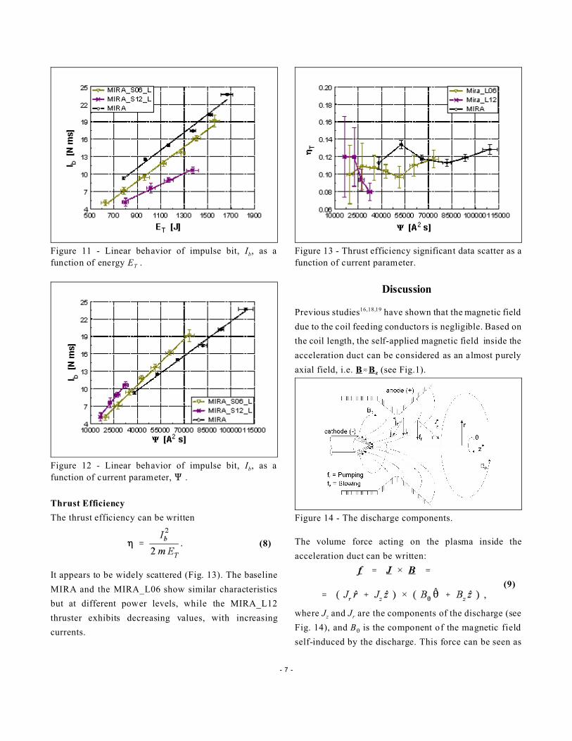
Impulse Bit
Impulse bit increases linearly as a function of both
energy, ET, and current parameter Q (Figs. 11, 12). A
comparison of the thruster systems at constant energy
shows:
(Ib)MIRA > (Ib)MIRA_L06 > (Ib)MIRA_L12 .
At constant current parameter, Q , the opposite holds.
- 7 -
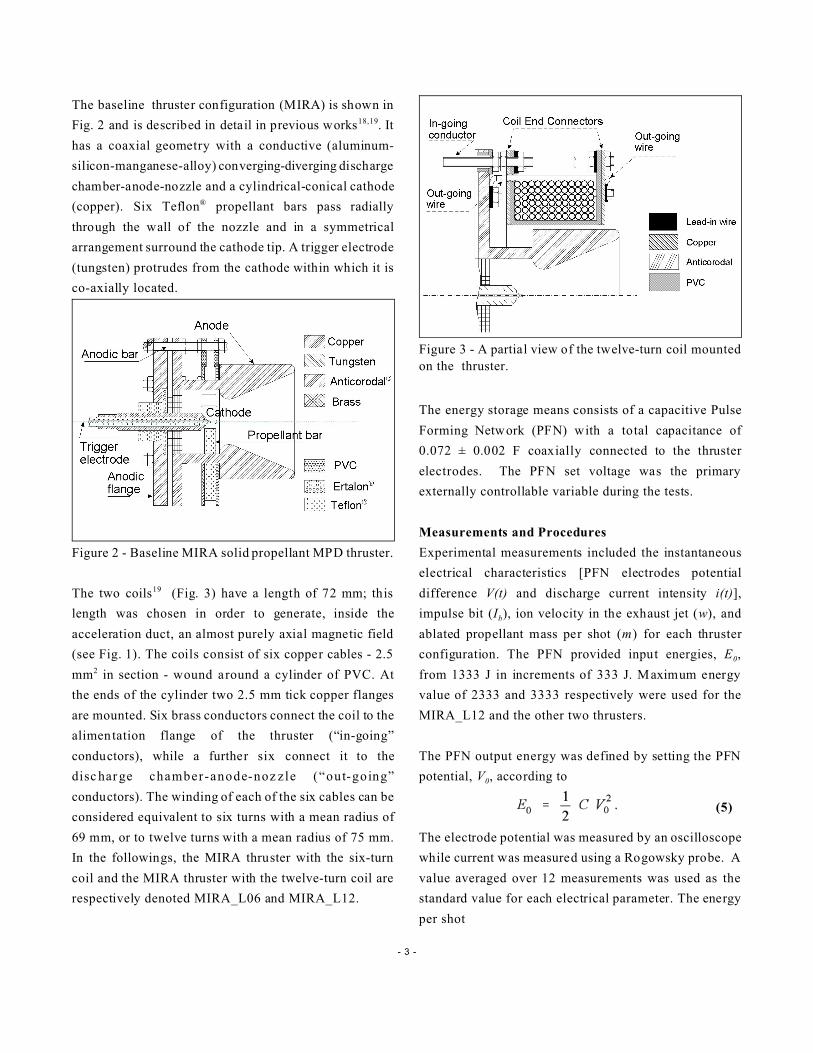
Figure 11 - Linear behavior of impulse bit, Ib, as a
function of energy ET .
Figure 12 - Linear behavior of impulse bit, Ib, as a
function of current parameter, Q .
Figure 13 - Thrust efficiency significant data scatter as a
function of current parameter.
Figure 14 - The discharge components.
(9)
(8)
Thrust Efficiency
The thrust efficiency can be written
It appears to be widely scattered (Fig. 13). The baseline
MIRA and the MIRA_L06 show similar characteristics
but at different power levels, while the MIRA_L12
thruster exhibits decreasing values, with increasing
currents.
Discussion
Previous studies16,18,19 have shown that the magnetic field
due to the coil feeding conductors is negligible. Based on
the coil length, the self-applied magnetic field inside the
acceleration duct can be considered as an almost purely
axial field, i.e. B.Bz (see Fig.1).
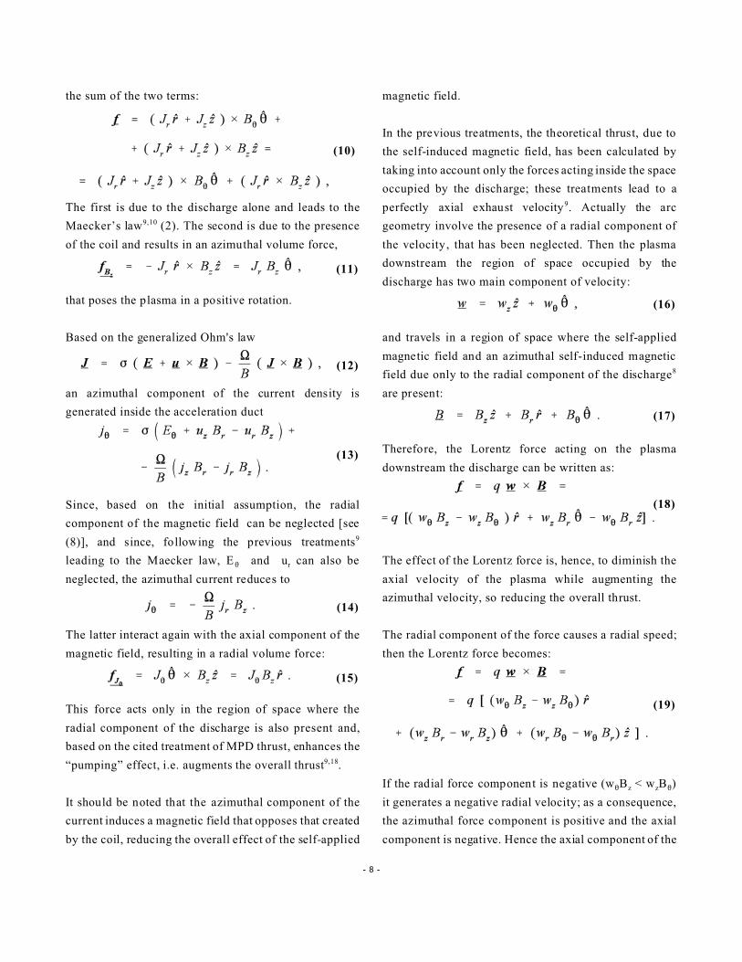
The volume force acting on the plasma inside the
acceleration duct can be written:
where Jz and Jr are the components of the discharge (see
Fig. 14), and B2 is the component of the magnetic field
self-induced by the discharge. This force can be seen as
- 8 -
(10)
(12)
(13)
(14)
(16)
(17)
(18)
(19)
(11)
(15)
the sum of the two terms:
The first is due to the discharge alone and leads to the
Maecker’s law9,10 (2). The second is due to the presence
of the coil and results in an azimuthal volume force,
that poses the plasma in a positive rotation.
Based on the generalized Ohm's law
an azimuthal component of the current density is
generated inside the acceleration duct
Since, based on the initial assumption, the radial
component of the magnetic field can be neglected [see
(8)], and since, following the previous treatments9
leading to the Maecker law, E2 and ur can also be
neglected, the azimuthal current reduces to
The latter interact again with the axial component of the
magnetic field, resulting in a radial volume force:
This force acts only in the region of space where the
radial component of the discharge is also present and,
based on the cited treatment of MPD thrust, enhances the
“pumping” effect, i.e. augments the overall thrust9,18.
It should be noted that the azimuthal component of the
current induces a magnetic field that opposes that created
by the coil, reducing the overall effect of the self-applied
magnetic field.
In the previous treatments, the theoretical thrust, due to
the self-induced magnetic field, has been calculated by
taking into account only the forces acting inside the space
occupied by the discharge; these treatments lead to a
perfectly axial exhaust velocity9. Actually the arc
geometry involve the presence of a radial component of
the velocity, that has been neglected. Then the plasma
downstream the region of space occupied by the
discharge has two main component of velocity:
and travels in a region of space where the self-applied
magnetic field and an azimuthal self-induced magnetic
field due only to the radial component of the discharge8
are present:
Therefore, the Lorentz force acting on the plasma
downstream the discharge can be written as:
The effect of the Lorentz force is, hence, to diminish the
axial velocity of the plasma while augmenting the
azimuthal velocity, so reducing the overall thrust.
The radial component of the force causes a radial speed;
then the Lorentz force becomes:
If the radial force component is negative (w2Bz < wzB2)
it generates a negative radial velocity; as a consequence,
the azimuthal force component is positive and the axial
component is negative. Hence the axial component of the

- 9 -
velocity decreases while the azimuthal component
increases until the radial component of the force becomes
positive (w2Bz > wzB2). If the radial component of the
velocity is positive and large enough that wrB2>w2Br the
opposite is true.
This force acts so that the radial component of the
plasma velocity oscillates between negative and positive
values. In other words, the plasma starts expanding and
contracting, while experiencing axial acceleration and
deceleration respectively.
The thrust is due to the “final” axial velocity of the
plasma i.e. to the velocity of the plasma no longer subject
to the Lorentz force. This occurs in the two following
cases:
- the plasma, moving away from the thruster, moves
through a magnetic field which becomes progressively
weaker; since the Lorentz force does no work on the
plasma, the speed holds constant, even if components
of the velocity change; such speed, sooner or later,
equals the local Alfven speed and the plasma is then
no longer influenced by the magnetic field22;
- the discharge expires and the magnetic field
disappears.
Electrical Parameters
At constant Q , the difference between the impedances of
MIRA_L12 and MIRA_L06_L is much bigger than the
one between the impedances of MIRA_L06 and MIRA.
This is consistent with the higher axial magnetic field
generated by the twelve-turn coil. In fact, at equal
currents, the strongest the axial magnetic field, the
biggest the potential difference necessary to bring the
electrons from the cathode to the anode. Therefore the
total impedance of the discharge path increases.
Ablated Mass
The higher ablated mass of the thrusters with the coil, at
constant Q , is due to the swirl generated by the self-
applied magnetic field: the azimuthal current and the hot
plasma, hitting the propellant bars, ablate more material.
The presence of the swirl in the propellant zone is
confirmed by experimental evidence16-19: in the thrusters
with a self-applied magnetic field, more remarkable
traces of propellant deposition were found on the sides of
the propellant bars hit by the swirling plasma.
Jet Exhaust Velocity
The characteristics of the exhaust velocity are consistent
with the K parameter. In particular, the highest velocity
values of MIRA_L12, compared to MIRA_L06, point to
the smaller divergence of the exhaust plume, due, once
more, to the higher self-applied magnetic field.
Impulse Bit
The experimental results show (Fig. 12) that, at equal Q ,
the positive thrust contribution due to the (14)
component is bigger than the negative contributions of
the other components [see (17)]. This effect increases as
the magnetic field increases.
The higher impedances, i.e. the higher energy losses,
justify the impulse bit, Ib, decrease as the self-applied
magnetic field increases, at constant energy, ET. In that
these losses are due to the coil impedance, the
employment of superconductor wires could be a solution
to be considered, in particular in the high power
propulsive systems.
Summary and Conclusions
Solid propellant MPD thruster behavior was examined
with self-applied magnetic fields of different intensities.
Two thrusters with respectively a six-turn and a twelve-
turn coil surrounding 7/9 of the same chamber-anode-
nozzle were tested along with the baseline thruster. The
same current which creates the discharge, also flows
through the coils. All thrusters used coaxial electrodes
with six radially-mounted Teflon® propellant bars
surrounding the cathode tip. Measurements included
electrical characteristics, impulse bit (thrust stand),
- 10 -
exhaust velocity (TOF Langmuir probe system), and
ablated propellant mass per shot.
The focus of the test program was to evaluate the effect
of the self-applied magnetic field on the thruster
performance as functions of ET and Q: The linearly
dependent behavior of ET and Q was also confirmed
for this type of thrusters.
At constant Q , higher self-applied magnetic fields lead to
higher impedances, higher ablated mass, and, most
importantly, higher impulse bit. The latter is due to the
the additional "pumping" effect caused by the interaction
between the discharge and the axial external magnetic
field inside the acceleration duct. The positive effect of
this is larger than the negative effect due to the
interaction between the external magnetic field and the
plasma exhaust flow in the remaining part of the
acceleration region (outside the discharge region).
On the other hand at constant energy, ET, the thrust
gained by applying the magnetic field does not justify the
energy lost to feed the coil. A remedy to this problem
could be to use a coil with superconductor wires.
Acknowledgments
We would like to thank C. Chingari for the precision
with which he fabricated all of the thruster components.
The funding provided by the Italian Space Agency (ASI)
and the Italian Ministry of Research (MURST) is
gratefully acknowledged.
References
[1] Paccani G., Petrucci L. and Deininger W. D., “Scale
Effec ts On Solid Prope llant MPD Thru ster
Performance”, AIAA Paper 98-3473, 34th JPC,
Cleveland, Ohio (USA), July 1998.
[2] Paccani G., "A Coaxial Non-Steady Solid Propellant
MPD Thruster Experimental Analysis", IEPC Paper
87-1095. 19th IEPC, Colorado Springs, Colorado
(USA),May 1987. - Journal of the British Interplanetary
Society Vol. 41, pp. 253-240, 1988.
[3] Paccani G., "Experimental Analysis of a Coaxial
Solid Propellant MPD Thruster with Segmented
Anodes", IEPC Paper 93-159, 23rd IEPC, Seattle,
Washinghton (USA), September 1993.
[4] Paccani G., Chiarotti U. and Deininger W. D.,
“Quasi-Steady Ablative Magneto-plasmadynamic
Thruster Performance with Different Propellants”,
Journal of Propulsion and Power, Vol..14, No. 2, pp.
254-260. March-April 1998.
[5] Paccani G., "Non-Steady Solid Propellant MPD
Thruster Experimental Analysis Concepts", IEPC Paper
90-2674, 21st IEPC, Orlando, Florida (USA), July 1990.
[6] Paccani G., "Studi sui Meccanismi Fisici di Base nei
Propulsori MPD"; ASI 92-RS-27 Report n 1, April 1993
(In Italian).
[7] Paccani G.: "Anode-Nozzle Experimental Analysis in
a Coaxial non Steady Solid Propellant MPD Thruster",
IEPC Paper 88-076, 20 th IEPC, Garmisch-
Partenkirchen, Germany, October 1988.
[8] Paccani G., Petrucci L. and Deininger W. D.,
"Experimental Analysis of a Solid Propellant MPD
Thruster with Different Anode Radii", IEPC Paper 99-
235, 26th IEPC., Kitakyushu, Japan, October 1999.
[9] Jahn G. R., “Physics of Electric Propulsion”, New
York: Mc Graw Hill, 1968.
[10] Maecker H., “Plasmastromungen in Licht-bogen
infolge eigenmagnetischer Kompression”, Zeitschrift für
Physik, Bd. 141, pp. 198-216, 1955 (in German).
- 11 -
[11] Krülle G. and Zeyfang E., “Preliminary Conclusions
of Continuous Applied Field Electromagnetic Thruster
Research at DFVLR”, AIAA paper 75-417, 11th IEPC,
New Orleans, Louisiana (USA), March 19-21, 1975.
[12] Tahara H., Sasaki M., Kagaya Y. and Yoshikawa T.,
“Thruster Performance and Acceleration Mechanisms of
a Quasi-steady Applied Field MPD Arcjet”, AIAA Paper
90-2554, 21st IEPC, Orlando, Florida (USA), July 18-
20, 1990.
[13] Sasoh A., “Thrust Formula for an Applied-Field
MPD Thruster Derived from Energy Conservation
Equation”. IEPC Paper 91-062, 22nd IEPC, Viareggio,
Italy, October 14-17, 1991.
[14] Lawless J. L. and Subramaniam V. V., “A Review
of the Theory of Self-Field MPD Thrusters”, IEPC
Paper 91-019, 22nd IEPC, Viareggio, Italy, October 14-
17, 1991.
[15] Sasoh A. and Arakawa Y.: “Electromagnetic Effects
in an Applied-Field Magnetoplasmadynamic Thruster”,
Journal of Propulsion and Power, Vol. 8, No. 1, January
1992.
[16] Paccani G.: “Solid-propellant Quasi-steady Mpd
Thrusters with Self-Applied Magnetic Field”, 32nd JPC,
Lake Buena Vista, FL (USA), July 1-3, 1996.
[17] Paccani G. and Petrucci L., “Self-Applied Magnetic
Field Effects On Solid Propellant MPD Thruster
Performance”, IEPC Paper 01-140, 27th IEPC,
Pasadena, California (USA), October 2001.
[18] Fiori L., “Propulsori MPD con Campo Magnetico
Autoapplicato”, LAUREA Thesis in Ingegneria
Aeronautica, Università degli Studi di Roma “La
Sapienza”, a.a. 1996-1997 (In Italian).
[19] Ralli C., “Analisi Sperimentale del Campo
Magnetico in Propulsori MPD”, LAUREA Thesis in
Ingegneria Aeronautica, Università degli Studi di Roma
“La Sapienza”, a.a. 1997-1998 (In Italian).
[20] Paccani G. and Ravignani R., "Sistema per la misura
della spinta di propulsori MPD", Aerotecnica, Missili e
Spazio, Vol. 72, pp. 42-51, No. 1, Jan-Jun 1994 (In
Italian).
[21] Paccani G. and Di Zenzo S., “Computerized Jet
Velocity Measurements in MPD Thrusters”, Aerotecnica,
Missili e Spazio, vol 74, No. 3-4, pp. 93-102, Jul-Dec
1995.
[22] Chang Diaz F., Squire J., Bengston R., Breizman
B., Baity F. and Carter M., “The Physics and
Engineering of the VASIMR Engine”, AIAA Paper
00-3756, 36th JPC, Huntsville, Alabama (USA), July
2000.