Selection and Application Guide Sentron Busway...
52
Selection and Application Guide Sentron Busway System usa.siemens.com/busway
Transcript of Selection and Application Guide Sentron Busway...
Selection and Application Guide
Sentron Busway System
usa.siemens.com/busway
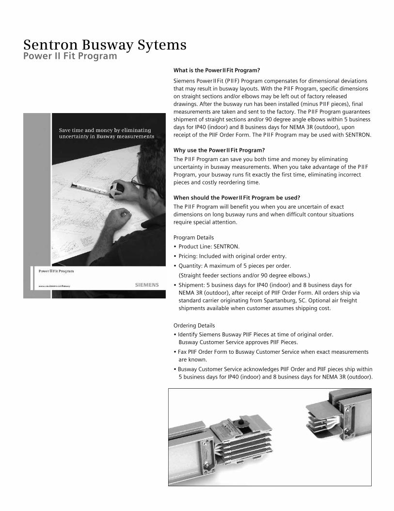
What is the Power II Fit Program?
Siemens Power II Fit (P II F) Program compensates for dimensional deviations that may result in busway layouts. With the P II F Program, specific dimensions on straight sections and/or elbows may be left out of factory released drawings. After the busway run has been installed (minus P II F pieces), final measurements are taken and sent to the factory. The P II F Program guarantees shipment of straight sections and/or 90 degree angle elbows within 5 business days for IP40 (indoor) and 8 business days for NEMA 3R (outdoor), upon receipt of the PIIF Order Form. The P II F Program may be used with SENTRON.
Why use the Power II Fit Program?
The P II F Program can save you both time and money by eliminating uncertainty in busway measurements. When you take advantage of the P II F Program, your busway runs fit exactly the first time, eliminating incorrect pieces and costly reordering time.
When should the Power II Fit Program be used?
The P II F Program will benefit you when you are uncertain of exact dimensions on long busway runs and when difficult contour situations require special attention.
Program Details
• Product Line: SENTRON.
• Pricing: Included with original order entry.
• Quantity: A maximum of 5 pieces per order.
(Straight feeder sections and/or 90 degree elbows.)
• Shipment: 5 business days for IP40 (indoor) and 8 business days for NEMA 3R (outdoor), after receipt of PIIF Order Form. All orders ship via standard carrier originating from Spartanburg, SC. Optional air freight shipments available when customer assumes shipping cost.
Ordering Details
• Identify Siemens Busway PIIF Pieces at time of original order. Busway Customer Service approves PIIF Pieces.
• Fax PIIF Order Form to Busway Customer Service when exact measurements are known.
• Busway Customer Service acknowledges PIIF Order and PIIF pieces ship within 5 business days for IP40 (indoor) and 8 business days for NEMA 3R (outdoor).
Sentron Busway SytemsPower II Fit Program
Sentron Busway Systems
Overview 2–3BusPlugOverview 4CatalogNumberingSystem 5TechnicalData 6–7StraightSections–Plug-in,RiserandFeeder 8WidthsandWeights 9Elbows 10–11Offsets 12Combinations 13Tees 14EndTapBoxes 15–16CenterTapBoxes 17In-lineDisconnectCubiclesandExpansionFittings 18ReducersandPhaseRotationFittings 19ServiceHeads 20–21Hangers 22–23HangersandEndClosers 24BuswayAccessories 25RoofandWallFlanges 26FlangedEnds 27–28PanelboardsandMeterCenterModules 29MeterCenterCubicles 30InstallationandApplicationInformation 31OrderEntryChecklist 32QuickReference 33BusPlugs 34-46GeneralNotes 47-48
Table of Contents
Busway selection and application guide

Sentron Busway Systems
Sentron Busway for Global Power Distribution ApplicationsBuilding on a solid foundation of advanced products for the construction industry, the Siemens Sentron name is recognized worldwide as synonymous with quality and consistent performance. Sentron Busway delivers impressive features and benefits that make it ideal for many types of industrial and construction implementations. Engineered to ensure the safe and efficient distribution of power in industrial, commercial and institutional environments world-wide, Sentron ampacities range from 225A to 5000A UL and IEC. Thanks to an innovative design, you benefit from labor-saving installation and a flexible, compact bus system that is an ideal fit for most applications. In fact, Sentron Busway is one of the industry’s least labor-intensive systems.
Sentron Busway installs with minimal hardware and often costs less than cable and conduit installations. The lightweight aluminum housing acts as an integral ground, joint stacks connect with splice plates featuring a single-bolt design, and bus plugs and cable tap boxes offer the industry’s largest wire bending space. An optional 200% neutral within the bus bar housing accommodates harmonics common in today’s power systems.
Sentron Busway conductors are insulated with a state-of-the-art epoxy insulation system, which is applied using an electrostatic spray process for optimal insulation integrity.
Exemplifying the spirit of continuing innovation, Sentron Busway is now available with economical and convenient elbow stacks for changing left, right, up or down directions at 90 degrees.
And, of course, Sentron Busway is certified to design standards worldwide, including UL, NEMA, IEC, CSA, VDE and BS.
Siemens Busway Business uses industry leading technology in all its manufacturing processes. From bus bar fabrication to Electrostatic Spray Epoxy insulation, all the processes used in the manufacturing of Siemens Sentron Busway are electronically controlled to provide for consistent, high quality results, making Sentron Busway products best in its class.
Housing Sentron Busway incorporates an all aluminum housing. This lightweight totally enclosed, non-ventilated housing resists rust and other elements, distributes heat away from the conductors, and provides an excellent ground path. The totally enclosed design also eliminates the need for derating of the system regardless of installation orientation. The housing is covered with an electrostatically applied light gray ANSI 61 polyester urethane powder paint that is scratch resistant and has a 1,000-hour salt spray resistance rating. Conductors Sentron Busway conductors have a compact construction and can be configured as 3-phase 3-wire, 3-phase 4-wire or 3-phase 4-wire with 200% neutral. The conductors may be ordered in copper (98% conductivity), 1000A/in2 M-Rated Copper, Aluminum (58% conductivity) and 750A/in2 L-Rated Aluminum. The optional 200% neutral helps to handle harmonic conditions that may exist. This system is especially useful with discharge lighting (fluorescent) and computer installations. This will help to minimize overheating and prolong the life cycle of your power distribution equipment.
Ground Sentron Busway offers ground options to meet your specifications: standard integral aluminum housing ground and optional internal grounding bars. An optional isolated ground is also available which is especially useful in applications where a clean ground is needed.
Plating All bus bars are electroplated with tin. This unique tin plating provides excellent conductivity and resists outside elements from attaching to the bars. Optional silver plating is also available.
Insulation Sentron Busway is insulated with an Epoxy Powder Coating system designed by Siemens Engineers, Epoxy System Engineers and Epoxy Powder Specialists, specifically for Siemens Busway products.
The Siemens exclusive Electrostatic Spray insulation process produces uniform application of Epoxy powder over the entire conductor bar. This is further enhanced by the inline filter process and magnetic separator that helps to eliminate contaminants common to fluidized bed systems. The electrostatic application also provides a better coating consistency than that of the older fluidized bed process. The combination of electrostatic spray and lower oven temperatures produces a consistent coverage with fewer impurities and pinholes in the insulation. The lower oven temperatures reduce the risk of bar annealing, which affects the overall quality of the system.
Sentron Busway insulation is Class B, 130°C Rated. Every bus bar and completed assembly is dielectric tested to ensure the insulation is free of defects.
Overview
2 Busway selection and application guide
Sentron Busway Systems
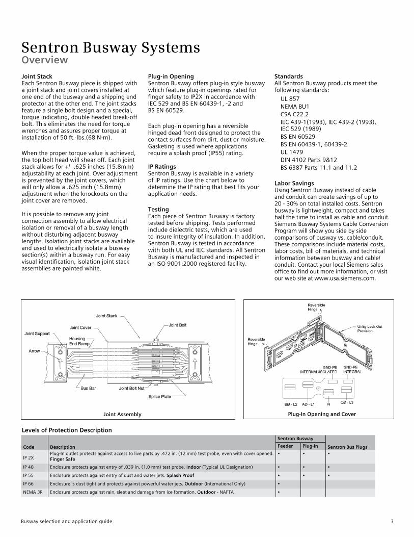
Joint Stack EachSentronBuswaypieceisshippedwithajointstackandjointcoversinstalledatoneendofthebuswayandashippingendprotectorattheotherend.Thejointstacksfeatureasingleboltdesignandaspecial,torqueindicating,doubleheadedbreak-offbolt.Thiseliminatestheneedfortorquewrenchesandassurespropertorqueatinstallationof50ft.-lbs.(68N-m).
Whenthepropertorquevalueisachieved,thetopboltheadwillshearoff.Eachjointstackallowsfor+/-.625inches(15.8mm)adjustabilityateachjoint.Overadjustmentispreventedbythejointcovers,whichwillonlyallowa.625inch(15.8mm)adjustmentwhentheknockoutsonthejointcoverareremoved.Itispossibletoremoveanyjointconnectionassemblytoallowelectricalisolationorremovalofabuswaylengthwithoutdisturbingadjacentbuswaylengths.Isolationjointstacksareavailableandusedtoelectricallyisolateabuswaysection(s)withinabuswayrun.Foreasyvisualidentification,isolationjointstackassembliesarepaintedwhite.
Plug-in Opening SentronBuswayoffersplug-instylebuswaywhichfeatureplug-inopeningsratedforfingersafetytoIP2XinaccordancewithIEC529andBSEN60439-1,-2andBSEN60529.
Eachplug-inopeninghasareversiblehingeddeadfrontdesignedtoprotectthecontactsurfacesfromdirt,dustormoisture.Gasketingisusedwhereapplicationsrequireasplashproof(IP55)rating.IP Ratings SentronBuswayisavailableinavarietyofIPratings.UsethechartbelowtodeterminetheIPratingthatbestfitsyourapplicationneeds.
Testing EachpieceofSentronBuswayisfactorytestedbeforeshipping.Testsperformedincludedielectrictests,whichareusedtoinsureintegrityofinsulation.Inaddition,SentronBuswayistestedinaccordancewithbothULandIECstandards.AllSentronBuswayismanufacturedandinspectedinanISO9001:2000registeredfacility.
Standards AllSentronBuswayproductsmeetthefollowingstandards:
UL857 NEMABU1 CSAC22.2 IEC439-1(1993),IEC439-2(1993),
IEC529(1989) BSEN60529 BSEN60439-1,60439-2 UL1479 DIN4102Parts9&12 BS6387Parts11.1and11.2
Labor Savings UsingSentronBuswayinsteadofcableandconduitcancreatesavingsofupto20-30%ontotalinstalledcosts.Sentronbuswayislightweight,compactandtakeshalfthetimetoinstallascableandconduit.SiemensBuswaySystemsCableConversionProgramwillshowyousidebysidecomparisonsofbuswayvs.cable/conduit.Thesecomparisonsincludematerialcosts,laborcosts,billofmaterials,andtechnicalinformationbetweenbuswayandcable/conduit.ContactyourlocalSiemenssalesofficetofindoutmoreinformation,orvisitourwebsiteatwww.usa.siemens.com.
Levels of Protection Description
Code Description
Sentron Busway
Sentron Bus PlugsFeeder Plug-In
IP2XPlug-Inoutletprotectsagainstaccesstolivepartsby.472in.(12mm)testprobe,evenwithcoveropened.Finger Safe
• • •
IP40 Enclosureprotectsagainstentryof.039in.(1.0mm)testprobe.Indoor(TypicalULDesignation) • • •
IP55 Enclosureprotectsagainstentryofdustandwaterjets.Splash Proof • • •
IP66 Enclosureisdusttightandprotectsagainstpowerfulwaterjets.Outdoor(InternationalOnly) •
NEMA3R Enclosureprotectsagainstrain,sleetanddamagefromiceformation.Outdoor-NAFTA •
Joint Assembly Plug-In Opening and Cover
Overview
Busway selection and application guide 3
Sentron Busway Systems
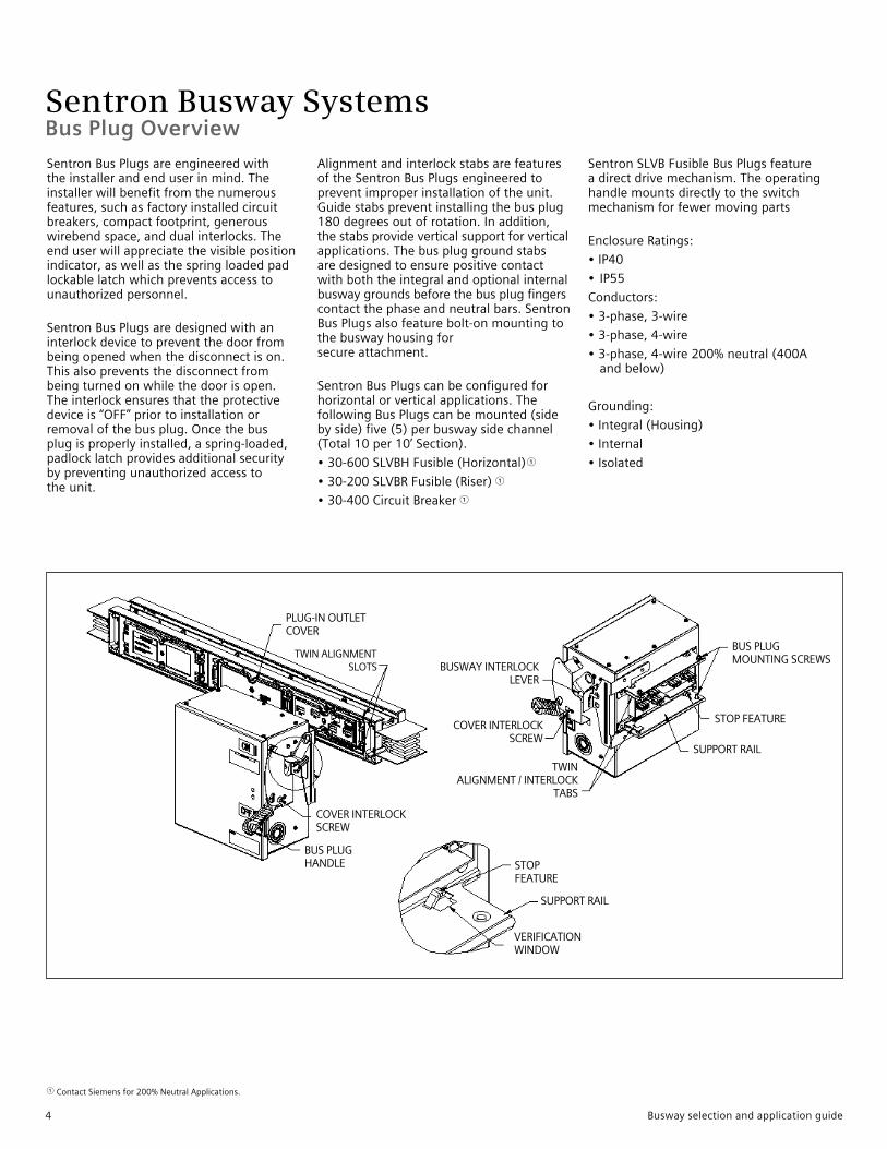
SentronBusPlugsareengineeredwiththeinstallerandenduserinmind.Theinstallerwillbenefitfromthenumerousfeatures,suchasfactoryinstalledcircuitbreakers,compactfootprint,generouswirebendspace,anddualinterlocks.Theenduserwillappreciatethevisiblepositionindicator,aswellasthespringloadedpadlockablelatchwhichpreventsaccesstounauthorizedpersonnel.
SentronBusPlugsaredesignedwithaninterlockdevicetopreventthedoorfrombeingopenedwhenthedisconnectison.Thisalsopreventsthedisconnectfrombeingturnedonwhilethedoorisopen.Theinterlockensuresthattheprotectivedeviceis“OFF”priortoinstallationorremovalofthebusplug.Oncethebusplugisproperlyinstalled,aspring-loaded,padlocklatchprovidesadditionalsecuritybypreventingunauthorizedaccesstotheunit.
AlignmentandinterlockstabsarefeaturesoftheSentronBusPlugsengineeredtopreventimproperinstallationoftheunit.Guidestabspreventinstallingthebusplug180degreesoutofrotation.Inaddition,thestabsprovideverticalsupportforverticalapplications.Thebuspluggroundstabsaredesignedtoensurepositivecontactwithboththeintegralandoptionalinternalbuswaygroundsbeforethebusplugfingerscontactthephaseandneutralbars.SentronBusPlugsalsofeaturebolt-onmountingtothebuswayhousingforsecureattachment.
SentronBusPlugscanbeconfiguredforhorizontalorverticalapplications.ThefollowingBusPlugscanbemounted(sidebyside)five(5)perbuswaysidechannel(Total10per10’Section).
•30-600SLVBHFusible(Horizontal)1
•30-200SLVBRFusible(Riser)1
•30-400CircuitBreaker1
SentronSLVBFusibleBusPlugsfeatureadirectdrivemechanism.Theoperatinghandlemountsdirectlytotheswitchmechanismforfewermovingparts
EnclosureRatings:
•IP40
•IP55
Conductors:
•3-phase,3-wire
•3-phase,4-wire
•3-phase,4-wire200%neutral(400Aandbelow)
Grounding:
•Integral(Housing)
•Internal
•Isolated
1 ContactSiemensfor200%NeutralApplications.
Bus Plug Overview
PLUG-INOUTLETCOVER
COVERINTERLOCKSCREW
BUSPLUGHANDLE
VERIFICATIONWINDOW
STOPFEATURE
BUSWAYINTERLOCKLEVER
COVERINTERLOCKSCREW
TWINALIGNMENT/INTERLOCK
TABS
STOPFEATURE
BUSPLUGMOUNTINGSCREWS
SUPPORTRAIL
SUPPORTRAIL
TWINALIGNMENTSLOTS
4 Busway selection and application guide
Sentron Busway Systems
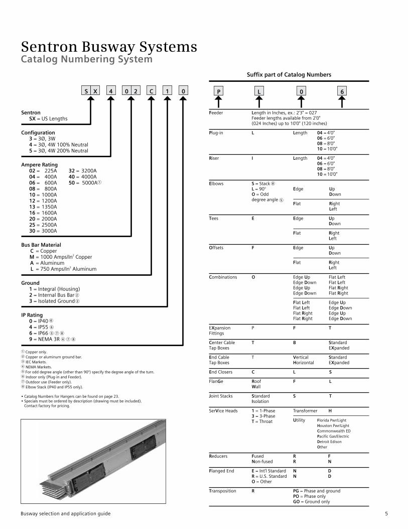
Suffix part of Catalog Numbers
Feeder LengthinInches,ex.:2'3"=027Feederlengthsavailablefrom2'0"(024Inches)upto10'0"(120inches)
Plug-in L Length 04 =4'0" 06 =6'0" 08 =8'0" 10 =10'0"
Riser I Length 04=4'0" 06=6'0" 08=8'0" 10=10'0"
Elbows S=Stack8 L=90° Edge Up O=Odd Down
degreeangle5
Flat Right Left
Tees E Edge Up Down
Flat Right Left
Offsets F Edge Up Down
Flat Right Left
Combinations O EdgeUp FlatLeft EdgeDown FlatLeft EdgeUp FlatRight EdgeDown FlatRight
FlatLeft EdgeUp FlatLeft EdgeDown FlatRight EdgeUp FlatRight EdgeDown
EXpansion P F TFittings
CenterCable T B StandardTapBoxes EXpanded
EndCable T Vertical StandardTapBoxes Horizontal EXpanded
EndClosers C L S
FlanGe Roof F L Wall
JointStacks Standard S T Isolation
SerViceHeads 1=1-Phase Transformer H
3=3-Phase
Utility FloridaPwr/Light
T=Throat HoustonPwr/Light
CommonwealthED PacificGas/Electric DetroitEdison Other
Reducers Fused R F Non-fused R N
FlangedEnd E=Int’lStandard N D R=U.S.Standard N D O=Other
Transposition R PG=Phaseandground PO=Phaseonly GO=Groundonly
P L 0 6
1Copperonly.2Copperoraluminumgroundbar.3IECMarkets.4NEMAMarkets.5Forodddegreeangle(otherthan90°)specifythedegreeangleoftheturn.6Indooronly(Plug-inandFeeder).7Outdooruse(Feederonly).8ElbowStack(IP40andIP55only).
•CatalogNumbersforHangerscanbefoundonpage23.•Specialsmustbeorderedbydescription(drawingmustbeincluded).
Contactfactoryforpricing.
Sentron SX=USLengths
Configuration 3=3Ø,3W 4=3Ø,4W100%Neutral 5=3Ø,4W200%Neutral
Ampere Rating 02= 225A 32= 3200A
04 = 400A 40= 4000A 06 = 600A 50 =5000A1 08= 800A 10=1000A 12=1200A 13=1350A 16=1600A 20=2000A 25=2500A 30=3000A
Bus Bar Material C =Copper M=1000Amps/In2Copper A =Aluminum L =750Amps/In2Aluminum
Ground 1=Integral(Housing) 2=InternalBusBar 2 3=IsolatedGround2
IP Rating 0=IP406 4=IP556 6=IP663 7 8 9=NEMA3R4 7 8
S X 4 0 2 C 1 0
Catalog Numbering System
Busway selection and application guide 5
Sentron Busway Systems
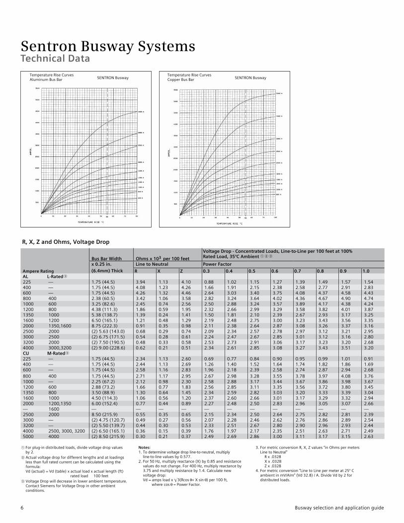
Ampere Rating
Bus Bar Width Ohms x 103 per 100 feet
Voltage Drop - Concentrated Loads, Line-to-Line per 100 feet at 100% Rated Load, 35°C Ambient 1 2 3
x 0.25 in.
(6.4mm) Thick
Line to Neutral Power Factor
R X Z 0.3 0.4 0.5 0.6 0.7 0.8 0.9 1.0 AL L-Rated3
225 — 1.75(44.5) 3.94 1.13 4.10 0.88 1.02 1.15 1.27 1.39 1.49 1.57 1.54400 — 1.75(44.5) 4.08 1.23 4.26 1.66 1.91 2.15 2.38 2.58 2.77 2.91 2.83600 — 1.75(44.5) 4.26 1.32 4.46 2.64 3.03 3.40 3.75 4.08 4.37 4.58 4.43800 400 2.38(60.5) 3.42 1.06 3.58 2.82 3.24 3.64 4.02 4.36 4.67 4.90 4.741000 600 3.25(82.6) 2.45 0.74 2.56 2.50 2.88 3.24 3.57 3.89 4.17 4.38 4.241200 800 4.38(111.3) 1.86 0.59 1.95 2.32 2.66 2.99 3.29 3.58 3.82 4.01 3.871350 1000 5.38(138.7) 1.39 0.24 1.41 1.50 1.81 2.10 2.39 2.67 2.93 3.17 3.251600 1200 6.50(165.1) 1.21 0.48 1.29 2.19 2.48 2.75 3.00 3.23 3.43 3.56 3.352000 1350,1600 8.75(222.3) 0.91 0.35 0.98 2.11 2.38 2.64 2.87 3.08 3.26 3.37 3.162500 2000 (2)5.63(143.0) 0.68 0.29 0.74 2.09 2.34 2.57 2.78 2.97 3.12 3.21 2.953000 2500 (2)6.75(171.5) 0.54 0.28 0.61 2.24 2.47 2.67 2.85 3.01 3.12 3.16 2.803200 2000 (2)7.50(190.5) 0.48 0.33 0.58 2.53 2.73 2.91 3.06 3.17 3.23 3.20 2.68
4000 3000,3200 (2)9.00(228.6) 0.62 0.21 0.51 2.34 2.61 2.85 3.08 3.27 3.43 3.51 3.20 CU M-Rated3
225 — 1.75(44.5) 2.34 1.13 2.60 0.69 0.77 0.84 0.90 0.95 0.99 1.01 0.91400 — 1.75(44.5) 2.44 1.13 2.69 1.26 1.40 1.52 1.64 1.74 1.82 1.86 1.69600 — 1.75(44.5) 2.58 1.16 2.83 1.96 2.18 2.39 2.58 2.74 2.87 2.94 2.68800 400 1.75(44.5) 2.71 1.17 2.95 2.67 2.98 3.28 3.55 3.78 3.97 4.08 3.761000 — 2.25(67.2) 2.12 0.98 2.30 2.58 2.88 3.17 3.44 3.67 3.86 3.98 3.671200 600 2.88(73.2) 1.66 0.77 1.83 2.56 2.85 3.11 3.35 3.56 3.72 3.80 3.451350 800 3.50(88.9) 1.30 0.64 1.45 2.34 2.59 2.82 3.03 3.20 3.33 3.39 3.041600 1000 4.50(114.3) 1.06 0.56 1.20 2.37 2.60 2.66 3.01 3.17 3.29 3.32 2.942000 1200,1350 6.00(152.4) 0.77 0.44 0.89 2.27 2.48 2.50 2.83 2.96 3.05 3.07 2.66— 1600 — — — — — — — — — — — —2500 2000 8.50(215.9) 0.55 0.35 0.65 2.15 2.34 2.50 2.64 2.75 2.82 2.81 2.393000 — (2)4.75(120.7) 0.49 0.27 0.56 2.07 2.28 2.46 2.62 2.76 2.86 2.89 2.543200 — (2)5.50(139.7) 0.44 0.30 0.53 2.33 2.51 2.67 2.80 2.90 2.96 2.93 2.444000 2500,3000,3200 (2)6.50(165.1) 0.36 0.15 0.39 1.76 1.97 2.17 2.35 2.51 2.63 2.71 2.495000 4000 (2)8.50(215.9) 0.30 0.21 0.37 2.49 2.69 2.86 3.00 3.11 3.17 3.15 2.63
1 Forplug-indistributedloads,dividevoltagedropvaluesby2.
2Actualvoltagedropfordifferentlengthsandatloadingslessthanfullratedcurrentcanbecalculatedusingtheformula:Vd(actual)=Vd(table)xactualloadxactuallength(ft)ratedload100feet
3VoltageDropwilldecreaseinlowerambienttemperature.ContactSiemensforVoltageDropinotherambientconditions.
Notes: 1.Todeterminevoltagedropline-to-neutral,multiply
line-to-linevaluesby0.577.2.For50Hz,multiplyreactance(X)by0.85andresistance
valuesdonotchange.For400Hz,multiplyreactanceby3.75andmultiplyresistanceby1.4.Calculatenewvoltagedrop:Vd=ampsloadxE3(Rcos +Xsin )per100ft,wherecos =PowerFactor.
3.FormetricconversionR,X,Zvalues”inOhmspermetersLinetoNeutral”Rx.0328Xx.0328Zx.0328
4.Formetricconversion”LinetoLinepermeterat25°CambientinmV/A/m”(Vd32.8)/A.DivideVdby2fordistributedloads.
Technical Data
R, X, Z and Ohms, Voltage Drop
TemperatureRiseCurvesAluminumBusBar
TemperatureRiseCurvesCopperBusBarSENTRONBusway SENTRONBusway
6 Busway selection and application guide
Sentron Busway Systems
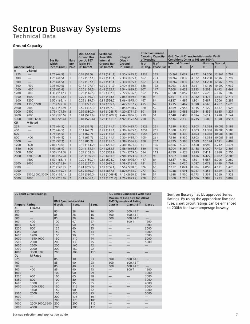
SentronBuswayhasULapprovedSeriesRatings.Byusingtheappropriatelinesidefuse,shortcircuitratingscanbeenhancedto200kAforloweramperagebusway.
UL Short Circuit Ratings UL Series Connected with Fuse
Ampere Rating RMS Symmetrical (kA)
Maximum Fuse Size for 200kA RMS Symmetrical Rating
6 cycle 1 sec. 3 sec. Class R Class J & T Class L AL L-Rated225 — 85 28 16 600 600J&T —400 — 85 28 16 600 600J&T —600 — 85 28 16 600 600J&T —800 400 100 47 27 — 800T 12001000 600 100 50 29 — — 30001200 800 125 60 35 — — 30001350 1000 150 75 43 — — 30001600 1200 150 90 52 — — 30002000 1350,1600 150 110 64 — — 50002500 2000 200 130 75 — — 50003000 2500 200 160 92 — — —3200 2000 200 160 92 — — —4000 3000,3200 200 200 115 — — —CU M-Rated225 — 85 40 23 600 600J&T —400 — 85 40 23 600 600J&T —600 — 85 40 23 600 600J&T —800 400 85 40 23 — 800T 16001000 — 100 50 29 — — 30001200 600 100 65 38 — — 30001350 800 100 80 46 — — 30001600 1000 125 95 55 — — 40002000 1200,1350 150 115 66 — — 5000— 1600 150 90 52 — — 30002500 2000 150 130 75 — — 50003000 — 200 175 101 — — —3200 — 200 175 101 — — —4000 2500,3000,3200 200 200 115 — — —5000 4000 200 200 115 — — —
Technical Data
Ampere Rating
Bus BarWidthInches (mm)
BarsperPole
Min. CSA forGround Busper UL 857Table 14In2 (mm2)
SectionalArea 50% InternalGround BarIn2 (mm2)
Integral (Hsg.)GroundIn2 (mm2)
Effective Current Carrying Capacityof Housing
Grd. Circuit Characteristics under FaultConditions Ohms x 103 per 100 ft.
% of UL Reg.
% of Phase Bar
Internal Ground Housing GroundR X Z R X Z
A L-Rated 225 — 1.75(44.5) 1 0.08(53.5) 0.22(141.1) 2.30(1485.1) 1333 253 10.267 9.037 4.872 14.200 12.963 5.797 400 — 1.75(44.5) 1 0.17(107.1) 0.22(141.1) 2.30(1485.1) 667 253 10.267 9.037 4.872 14.200 12.963 5.797 600 — 1.75(44.5) 1 0.17(107.1) 0.22(141.1) 2.30(1485.1) 667 253 10.267 9.037 4.872 14.200 12.963 5.797 800 400 2.38(60.5) 1 0.17(107.1) 0.30(191.9) 2.40(1550.1) 688 192 8.063 7.333 3.351 11.150 10.000 4.9321000 600 3.25(82.6) 1 0.20(126.5) 0.41(262.1) 2.54(1639.9) 607 147 7.208 6.628 2.833 9.202 8.442 3.6621200 800 4.38(111.1) 1 0.23(146.5) 0.55(352.8) 2.72(1756.6) 552 115 6.358 5.852 2.487 7.625 6.926 3.1891350 1000 5.38(136.5) 1 0.29(189.7) 0.67(433.5) 2.88(1859.8) 446 9 5.561 5.115 2.182 6.478 5.883 2.7131600 1200 6.50(165.1) 1 0.29(189.7) 0.81(524.2) 3.06(1975.4) 467 84 4.837 4.489 1.801 5.687 5.206 2.2892000 1350,1600 8.75(222.3) 1 0.35(227.7) 1.09(705.6) 3.42(2207.7) 425 69 3.735 3.467 1.390 4.565 4.267 1.6232500 2000 5.63(142.9) 2 0.52(332.3) 1.41(907.3) 3.85(2480.7) 320 59 3.169 2.955 1.145 4.129 3.837 1.5263000 2500 6.75(171.5) 2 0.59(380.0) 1.69(1088.7) 4.20(2711.9) 301 53 2.848 2.683 0.954 3.835 3.635 1.2213200 2000 7.50(190.5) 2 0.81(522.6) 1.88(1209.7) 4.44(2866.8) 229 51 2.648 2.493 0.894 3.614 3.428 1.1444000 3000,3200 9.00(228.6) 2 0.81(522.6) 2.25(1451.6) 4.92(3176.5) 250 50 2.446 2.339 0.715 3.500 3.378 0.916CU M-Rated225 — 1.75(44.5) 1 0.05(33.5) 0.22(141.1) 2.30(1485.1) 2128 261 7.380 6.330 3.803 11.338 10.083 5.183400 — 1.75(44.5) 1 0.11(67.7) 0.22(141.1) 2.30(1485.1) 1054 261 7.380 6.330 3.803 11.338 10.083 5.183600 — 1.75(44.5) 1 0.11(67.7) 0.22(141.1) 2.30(1485.1) 1054 261 7.380 6.330 3.803 11.338 10.083 5.183800 400 1.75(44.5) 1 0.11(67.7) 0.22(141.1) 2.30(1485.1) 1054 261 7.380 6.330 3.803 11.338 10.083 5.1831000 — 2.25(57.2) 1 0.13(85.2) 0.28(181.5) 2.38(1536.7) 860 207 6.715 5.993 3.029 10.194 9.191 4.4091200 600 2.88(73.0) 1 0.18(114.2) 0.36(231.9) 2.48(1601.8) 661 166 6.186 5.676 2.460 8.996 8.212 3.6741350 800 3.50(88.9) 1 0.24(152.3) 0.44(282.3) 2.58(1665.8) 510 140 5.704 5.267 2.188 8.000 7.492 2.8071600 1000 4.50(114.3) 1 0.24(152.3) 0.56(362.9) 2.74(1769.0) 534 113 4.719 4.323 1.893 7.411 6.880 2.7562000 1200,1350 6.00(152.4) 1 0.29(189.7) 0.75(483.9) 2.98(1923.8) 457 90 3.507 3.181 1.476 6.422 6.032 2.205— 1600 6.50(165.1) 1 0.29(189.7) 0.81(524.2) 3.06(1975.4) 467 84 4.837 4.489 1.801 5.687 5.206 2.2892500 2000 8.50(215.9) 1 0.35(227.7) 1.06(685.5) 3.38(2181.9) 421 70 2.294 2.020 1.087 3.072 5.419 1.7643000 — 4.75(120.7) 2 0.41(265.8) 1.19(766.1) 3.56(2290.0) 376 66 2.117 1.874 0.984 4.859 4.631 1.4703200 — 5.50(139.7) 2 0.59(380.0) 1.38(887.1) 3.80(2453.9) 277 60 1.938 1.691 0.947 4.353 4.129 1.3784000 2500,3000,3200 6.50(165.1) 2 0.59(380.0) 1.63(1048.4) 4.12(2660.3) 296 54 1.688 1.500 0.773 3.334 3.060 1.3235000 4000 8.50(215.9) 2 0.71(456.1) 2.13(1371.0) 4.76(3073.2) 278 50 1.360 1.218 0.606 1.989 1.783 0.882
Ground Capacity
Busway selection and application guide 7

Sentron Busway SystemsStraight Sections – Plug-in, Riser and Feeder
Straight Sections SentronBuswaycanbeorderedwithAluminumorCopperbusbars.Aluminumbarsareavailablein225-4000amperesections.Copperbarsareavailablein225-5000amperesections.SentronBuswayincludesanintegralhousingground,andisavailablewithaninternalgroundbaroranisolatedgroundbarinallampereratings.SentronBuswayhousingisafour-piecealuminumdesign.
Plug-In Sections Sentronplug-insectionsaredesignedwithplug-inopeningscenteredon24in.(610mm)intervals,andarelocatedonbothsidesofthebuswayforoptimumutilization.Plug-insectionsareavailableinstandardlengthsof4ft.(1.22m),6ft.(1.83m),8ft.(2.44m)and10ft.(3.05m).
Sentronplug-insectionsmeetIP40(indoor)andIP55(splashproof)requirements.Onejointstackassemblyisprovidedwitheachplug-insection.
Riser Sections SentronRisersectionsaredesignedwithplug-inopeningscenteredon24in.(610mm)intervalsononesideofthebuswayonly.Thiseliminatesunusableplug-inoutletsinverticalapplications.Riserbuswayisavailableinstandardlengthsof4ft.(1.22m),6ft.(1.83m),8ft.(2.44m)and10ft.(3.05m).SentronRiserBuswayisavailableinIP40(indoor)andIP55(splashproof).Onejointstackassemblyisprovidedwitheachrisersection.
Plug-In Outlet Features Theplug-inoutletmoldedguarddesignpreventsincidentalfingercontactwithliveconductors.Sentronplug-inoutletsare
IP2Xrated(withtheoutletcoveropen)whichmeansa.472in.(12mm)orlargerprobeisunabletoenteraplug-inoutlet.TheoutletisIP40RatedwiththecoverclosedandIP55Ratedwhenconfiguredwithgaskets.
Feeder Sections Feederbuswaycarriesthecurrentofthebuswaysystemfromthesupplysource.Feederbuswaydoesnothaveplug-inoutlets.SentronFeederbuswayisavailableincustomlengthsfrom2ft.(.61m)to10ft.(3.05m).FeedersectionsareratedasIP40(Indoor),IP55(SplashProof),NEMA3R(Outdoor),andIP66(SevereOutdoor).Onejointstackassemblyisprovidedwitheachfeedersection.
Standard Plug-In Section (Standard plug-in outlets on both sides on 24 in. centers) Suffix PL04 (4 ft.), PL06 (6 ft.), PL08 (8 ft.), PL10 (10 ft.)
Standard Riser Section (Standard Plug-In outlets on one side on 24 in. centers) Suffix RI04 (4 ft.), RI06 (6 ft.), RI08 (8 ft.), RI10 (10 ft.)
Standard Feeder Section Suffix F024 - 120 (last 3 digits = length in Inches, 024=24 in., 120=120 in.)
8 Busway selection and application guide

Sentron Busway SystemsWidths and Weights
Sentron Busway, Widths and Weights
Ampere RatingDimensioninches (mm)
Approximate Weight - lbs per ft. (kg per meter)
3Ø, 3-Wire
3Ø, 3-Wirewith InternalGround 3Ø, 4-Wire
3Ø, 4-Wirewith InternalGround
3Ø, 4-Wire200%Neutral
3Ø, 4-Wire 200% Neutral with InternalGround
AL L-Rated 225 — “W1” 3.9(99) 5(8) 5(8) 6(9) 6(9) 7(10) 7(10)400 — “W1” 3.9(99) 5(8) 5(8) 6(9) 6(9) 7(10) 7(10)600 — “W1” 3.9(99) 5(8) 5(8) 6(9) 6(9) 7(10) 7(10)800 400 “W1” 4.6(117) 6(9) 6(9) 7(10) 7(10) 7(11) 8(11)1000 600 “W1” 5.4(137) 7(10) 7(11) 8(12) 8(12) 9(13) 9(14)1200 800 “W1” 6.6(168) 8(12) 9(13) 9(14) 10(15) 11(16) 11(17)1350 1000 “W1” 7.6(193) 9(13) 10(15) 11(16) 11(17) 12(18) 13(19)1600 1200 “W1” 8.7(221) 10(15) 11(17) 12(18) 13(19) 14(21) 15(22)2000 1250,1600 “W1” 10.9(277) 13(19) 14(21) 15(23) 16(24) 18(26) 19(28)2500 2000 “W2” 13.7(348) 15(22) 17(25) 18(27) 20(30) 22(33) 23(34)3000 2500 “W2” 15.8(402) 17(25) 19(28) 21(31) 23(34) 25(37) 27(40)3200 2000 “W2” 17.3(439) 18(27) 20(30) 23(34) 25(37) 27(40) 29(43)4000 3000,3200 “W2” 20.3(516) 22(33) 25(37) 27(40) 30(44) 32(48) 35(52)CU M-Rated225 — “W1” 3.9(99) 9(13) 10(14) 10(16) 11(17) 12(18) 13(19)400 — “W1” 3.9(99) 9(13) 10(14) 10(16) 11(17) 12(18) 13(19)600 — “W1” 3.9(99) 9(13) 10(14) 10(16) 11(17) 12(18) 13(19)800 400 “W1” 3.9(99) 9(13) 10(14) 10(16) 11(17) 12(18) 13(19)1000 — “W1” 4.4(112) 10(15) 11(17) 12(19) 14(20) 15(22) 16(23)1200 600 “W1” 5.1(130) 12(18) 14(20) 15(23) 16(24) 18(26) 19(29)1350 800 “W1” 5.7(145) 14(21) 16(24) 17(26) 19(29) 21(31) 23(34)1600 1000 “W1” 6.7(170) 17(26) 19(29) 22(32) 24(35) 26(38) 28(42)2000 1200,1350 “W1” 8.2(208) 22(32) 25(37) 28(41) 30(45) 33(50) 36(54)— 1600 “W1” 10.9(277) 24(35) 27(40) 30(44) 32(48) 36(54) 39(58)2500 2000 “W1” 10.7(272) 30(44) 34(50) 38(56) 42(62) 46(68) 50(74)3000 — “W2” 11.8(300) 33(49) 37(55) 42(63) 47(70) 51(76) 56(83)3200 — “W2” 13.3(335) 37(55) 42(63) 48(72) 53(79) 58(86) 64(95)4000 2500,3000,3200 “W2” 15.3(389) 43(64) 50(75) 56(83) 62(92) 68(101) 75(112)5000 4000 “W2” 19.3(491) 56(83) 64(95) 72(107) 80(119) 89(132) 97(145)
Busway selection and application guide 9

Sentron Busway Systems
Edge Down Edge Up
Suffix ESED Suffix ESEU
Edgewise Elbow Stacks Edgewiseelbowstackscreateupanddowndirectionalchanges.The“A”phaseisontheinsideofthebendforedgeupelbowstacks.The“A”phaseisontheoutsideofthebendforedgedownelbowstacks.
Flatwise Elbow Stacks Flatwiseelbowstacksareusedforleftandrightdirectionalchanges.Whenthebuswaysystemismountedflatwiseinthehorizontalplane(busbarsrunparalleltothefloor).
Edgewise Elbow Stacks, Dimensions (standard/min.)Ampere Rating Dimensions Inches (mm) “A”AL L-Rated225 — 4.25(108)400 — 4.25(108)600 — 4.25(108)800 400 4.25(108)1000 600 4.25(108)1200 800 4.25(108)1350 1000 4.25(108)1600 1200 4.25(108)2000 1350,1600 4.25(108)2500 2000 4.25(108)3000 2500 4.25(108)3200 2000 4.25(108)4000 3000,4300 4.25(108)CU M-Rated225 — 4.25(108)400 — 4.25(108)600 — 4.25(108)800 400 4.25(108)1000 — 4.25(108)1200 600 4.25(108)1350 800 4.25(108)1600 1000 4.25(108)2000 1200,1350 4.25(108)— 1600 4.25(108)2500 2000 4.25(108)3000 — 4.25(108)3200 — 4.25(108)4000 2500,3000,3200 4.25(108)
Flatwise Elbow Stacks, Dimensions (standard/min.)
Ampere Rating Dimensions Inches (mm) “A”AL L-Rated225 — 1.00(25)400 — 1.00(25)600 — 1.00(25)800 400 1.12(281000 600 2.00(51)1200 800 2.50(64)1350 1000 3.00(76)1600 1200 3.50(89)2000 1350,1600 4.62(117)2500 2000 5.75(146)3000 2500 7.00(178)3200 2000 7.75(197)4000 3000,3200 9.35(237)CU M-Rated225 — 1.00(25)400 — 1.00(25)600 — 1.00(25)800 400 1.00(25)1000 — 1.12(28)1200 600 1.25(33)1350 800 2.00(50)1600 1000 2.50(64)2000 1200,1350 3.25(83)— 1600 4.62(117)2500 2000 4.50(114)3000 — 5.00(127)3200 — 5.75(146)4000 2500,3000,3200 6.75(171)5000 4000 8.87(225)
Note:Flatwiseelbowstackscanbeorderedaseitherright-hand(ESFR)orleft-hand(ESFL)tofollowthesamenomenclatureasanelbowsection.Theconstructionisidenticalandinterchangeable.
SentronBuswayelbowsprovideasimple,convenientmethodofchangingthedirection(left,right,upordown)ofabuswayrun.Twoelbowstylesareoffered:elbowstackandelbowsection.
Flat
Suffix ESFR/ESFL
Elbows
10 Busway selection and application guide

Sentron Busway SystemsElbows
Flatwise Elbow Sections Flatwiseelbowsectionsareusedforleftandrightdirectionalchangeswhenthebuswaysystemismountedinthehorizontalplane(busbarsrunparalleltothefloor).Thejointstackassemblymaybemovedtotheoppositelegtochangetheorientationfromlefttoright/righttoleft.
Edgewise Elbow Sections Edgewiseelbowsectionscreateupanddowndirectionalchanges.The“A”phasebusbarliesontheinsideofthebendforedgeupelbows.The“A”phasebusbarliesontheoutsideofthebendforedgedownelbows.Thejointstackassemblyonedgewiseelbowscannotbemovedinordertochangeorientationfromuptodown/downtoup.SentronBuswayelbowsectionsareshippedwithajointstackassemblyononeendfordirectconnectiontothebuswaysystem.
Flatwise Elbow Sections, Dimensions (standard/min.)
Ampere Rating
Dimensions Inches (mm)
“A” ”B”AL L-Rated225 — 12(305) 12(305)400 — 12(305) 12(305)600 — 12(305) 12(305)800 400 12(305) 12(305)1000 600 12(305) 12(305)1200 800 12(305) 12(305)1350 1000 12(305) 12(305)1600 1200 18(457) 18(457)2000 1350,1600 18(457) 18(457)2500 2000 18(457) 18(457)3000 2500 18(457) 18(457)3200 2000 18(457) 18(457)4000 3000,3200 24(610) 24(610)CU M-Rated
225 — 12(305) 12(305)400 — 12(305) 12(305)600 — 12(305) 12(305)800 400 12(305) 12(305)1000 — 12(305) 12(305)1200 600 12(305) 12(305)1350 800 12(305) 12(305)1600 1000 12(305) 12(305)2000 1200,1350 12(305) 12(305)— 1600 18(457) 18(457)2500 2000 18(457) 18(457)3000 — 18(457) 18(457)3200 — 18(457) 18(457)4000 2500,3000,3200 18(457) 18(457)5000 4000 24(610) 24(610)
Edgewise Elbow Sections, Dimensions (standard/min.)
Ampere Rating
Dimensions Inches (mm)
“A” ”B”AL L-Rated225 — 10(254) 10(254)400 — 10(254) 10(254)600 — 10(254) 10(254)800 400 10(254) 10(254)1000 600 10(254) 10(254)1200 800 10(254) 10(254)1350 1000 10(254) 10(254)1600 1200 10(254) 10(254)2000 1350,1600 10(254) 10(254)2500 2000 10(254) 10(254)3000 2500 10(254) 10(254)3200 2000 10(254) 10(254)4000 3000,3200 10(254) 10(254)CU M-Rated
225 — 10(254) 10(254)400 — 10(254) 10(254)600 — 10(254) 10(254)800 400 10(254) 10(254)1000 — 10(254) 10(254)1200 600 10(254) 10(254)1350 800 10(254) 10(254)1600 1000 10(254) 10(254)2000 1200,1350 10(254) 10(254)— 1600 10(254) 10(254)2500 2000 10(254) 10(254)3000 — 10(254) 10(254)3200 — 10(254) 10(254)4000 2500,3000,3200 10(254) 10(254)5000 4000 10(254) 10(254)
Note:Oddangleelbowflatwiseandedgewiseelbowsectionsareavailableforangles95°-175°in5°increments.
Flat Right
Suffix ELFR
Flat Left
Suffix ELEF
Edge Up Edge Down
Suffix ELEU Suffix ELED
Busway selection and application guide 11

Sentron Busway Systems
Edge Up
Suffix OFEU
Offsetscanbeutilizedtosolvedifficultcontourproblemsandsavespace.Inapplicationswherespacedoesnotallowfortwoconnectedelbows,asingleoffsetcanbypassanobstruction.Alloffsetsaresuppliedwithonejointstackassembly.
Flatwise Offsets, Dimensions (standard/min.)
Ampere RatingDimensions Inches (mm)*“A” ”B” ”C”
AL L-Rated225 — 12(305) 5(127) 12(305)400 — 12(305) 5(127) 12(305)600 — 12(305) 5(127) 12(305)800 400 12(305) 5(127) 12(305)1000 600 12(305) 5(127) 12(305)1200 800 12(305) 5(127) 12(305)1350 1000 12(305) 5(127) 12(305)1600 1200 18(457) 5(127) 18(457)2000 1350,1600 18(457) 5(127) 18(457)2500 2000 18(457) 5(127) 18(457)3000 2500 18(457) 5(127) 18(457)3200 2000 18(457) 5(127) 18(457)4000 3000,3200 24(610) 8(203) 24(610)CU M-Rated225 — 12(305) 5(127) 12(305)400 — 12(305) 5(127) 12(305)600 — 12(305) 5(127) 12(305)800 400 12(305) 5(127) 12(305)1000 — 12(305) 5(127) 12(305)1200 600 12(305) 5(127) 12(305)1350 800 12(305) 5(127) 12(305)1600 1000 12(305) 5(127) 12(305)2000 1200,1350 12(305) 5(127) 12(305)— 16002500 2000 18(457) 5(127) 18(457)3000 — 18(457) 5(127) 18(457)3200 — 18(457) 5(127) 18(457)4000 2500,3000,3200 18(457) 5(127) 18(457)5000 4000 24(610) 8(203) 24(610)
Edgewise Offsets, Dimensions (standard/min.)
Ampere RatingDimensions Inches (mm)*“A” ”B” ”C”
AL L-Rated225 — 10(254) 6(152) 10(254)400 — 10(254) 6(152) 10(254)600 — 10(254) 6(152) 10(254)800 400 10(254) 6(152) 10(254)1000 600 10(254) 6(152) 10(254)1200 800 10(254) 6(152) 10(254)1350 1000 10(254) 6(152) 10(254)1600 1200 10(254) 6(152) 10(254)2000 1350,1600 10(254) 6(152) 10(254)2500 2000 10(254) 6(152) 10(254)3000 2500 10(254) 6(152) 10(254)3200 2000 10(254) 6(152) 10(254)4000 3000,3200 10(254) 6(152) 10(254)CU M-Rated225 — 10(254) 6(152) 10(254)400 — 10(254) 6(152) 10(254)600 — 10(254) 6(152) 10(254)800 400 10(254) 6(152) 10(254)1000 — 10(254) 6(152) 10(254)1200 600 10(254) 6(152) 10(254)1350 800 10(254) 6(152) 10(254)1600 1000 10(254) 6(152) 10(254)2000 1200,1350 10(254) 6(152) 10(254)— 1600 10(254) 6(152) 10(254)2500 2000 10(254) 6(152) 10(254)3000 — 10(254) 6(152) 10(254)3200 — 10(254) 6(152) 10(254)4000 2500,3000,3200 10(254) 6(152) 10(254)5000 4000 10(254) 6(152) 10(254)
Edge Down
Suffix OFED
Flat Right
Suffix OFFR
Flat Left
Suffix OFFL
Offsets
Note:LegdimensionsAandChavebeenreversedfrompriorpublications.
12 Busway selection and application guide
Sentron Busway SystemsCombinations
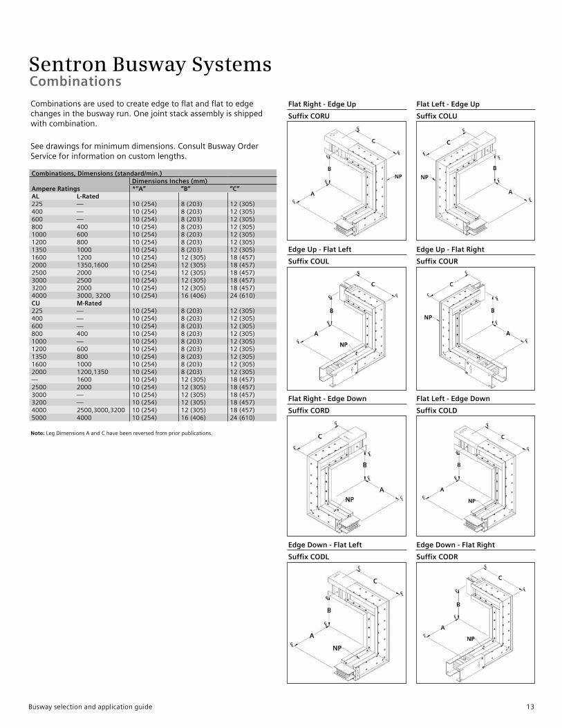
Flat Right - Edge Up Flat Left - Edge Up
Suffix CORU Suffix COLU
Edge Up - Flat Left Edge Up - Flat Right
Suffix COUL Suffix COUR
Flat Right - Edge Down Flat Left - Edge Down
Suffix CORD Suffix COLD
Edge Down - Flat Left Edge Down - Flat Right
Suffix CODL Suffix CODR
Combinationsareusedtocreateedgetoflatandflattoedgechangesinthebuswayrun.Onejointstackassemblyisshippedwithcombination.
Seedrawingsforminimumdimensions.ConsultBuswayOrderServiceforinformationoncustomlengths.
Combinations, Dimensions (standard/min.)
Ampere RatingsDimensions Inches (mm)*“A” ”B” ”C”
AL L-Rated225 — 10(254) 8(203) 12(305)400 — 10(254) 8(203) 12(305)600 — 10(254) 8(203) 12(305)800 400 10(254) 8(203) 12(305)1000 600 10(254) 8(203) 12(305)1200 800 10(254) 8(203) 12(305)1350 1000 10(254) 8(203) 12(305)1600 1200 10(254) 12(305) 18(457)2000 1350,1600 10(254) 12(305) 18(457)2500 2000 10(254) 12(305) 18(457)3000 2500 10(254) 12(305) 18(457)3200 2000 10(254) 12(305) 18(457)4000 3000,3200 10(254) 16(406) 24(610)CU M-Rated225 — 10(254) 8(203) 12(305)400 — 10(254) 8(203) 12(305)600 — 10(254) 8(203) 12(305)800 400 10(254) 8(203) 12(305)1000 — 10(254) 8(203) 12(305)1200 600 10(254) 8(203) 12(305)1350 800 10(254) 8(203) 12(305)1600 1000 10(254) 8(203) 12(305)2000 1200,1350 10(254) 8(203) 12(305)— 1600 10(254) 12(305) 18(457)2500 2000 10(254) 12(305) 18(457)3000 — 10(254) 12(305) 18(457)3200 — 10(254) 12(305) 18(457)4000 2500,3000,3200 10(254) 12(305) 18(457)5000 4000 10(254) 16(406) 24(610)
Note:LegDimensionsAandChavebeenreversedfrompriorpublications.
Busway selection and application guide 13
Sentron Busway SystemsTees
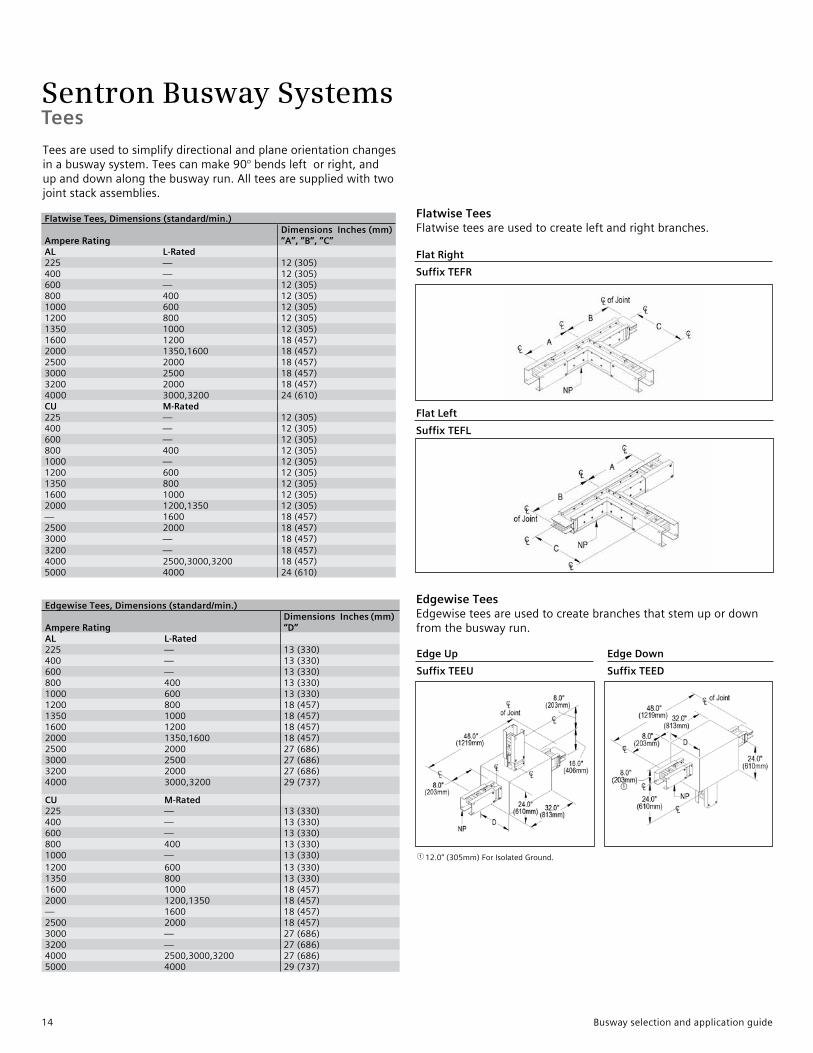
Flat Right
Suffix TEFR
Flat Left
Suffix TEFL
Flatwise Tees Flatwiseteesareusedtocreateleftandrightbranches.
Edgewise Tees Edgewiseteesareusedtocreatebranchesthatstemupordownfromthebuswayrun.
Flatwise Tees, Dimensions (standard/min.)
Ampere RatingDimensions Inches (mm)“A”, ”B”, ”C”
AL L-Rated225 — 12(305)400 — 12(305)600 — 12(305)800 400 12(305)1000 600 12(305)1200 800 12(305)1350 1000 12(305)1600 1200 18(457)2000 1350,1600 18(457)2500 2000 18(457)3000 2500 18(457)3200 2000 18(457)4000 3000,3200 24(610)CU M-Rated225 — 12(305)400 — 12(305)600 — 12(305)800 400 12(305)1000 — 12(305)1200 600 12(305)1350 800 12(305)1600 1000 12(305)2000 1200,1350 12(305)— 1600 18(457)2500 2000 18(457)3000 — 18(457)3200 — 18(457)4000 2500,3000,3200 18(457)5000 4000 24(610)
Edgewise Tees, Dimensions (standard/min.)
Ampere RatingDimensions Inches (mm)“D”
AL L-Rated225 — 13(330)400 — 13(330)600 — 13(330)800 400 13(330)1000 600 13(330)1200 800 18(457)1350 1000 18(457)1600 1200 18(457)2000 1350,1600 18(457)2500 2000 27(686)3000 2500 27(686)3200 2000 27(686)4000 3000,3200 29(737)
CU M-Rated225 — 13(330)400 — 13(330)600 — 13(330)800 400 13(330)1000 — 13(330)1200 600 13(330)1350 800 13(330)1600 1000 18(457)2000 1200,1350 18(457)— 1600 18(457)2500 2000 18(457)3000 — 27(686)3200 — 27(686)4000 2500,3000,3200 27(686)5000 4000 29(737)
Edge Up Edge Down
Suffix TEEU Suffix TEED
112.0"(305mm)ForIsolatedGround.
Teesareusedtosimplifydirectionalandplaneorientationchangesinabuswaysystem.Teescanmake90°bendsleftorright,andupanddownalongthebuswayrun.Allteesaresuppliedwithtwojointstackassemblies.
a
14 Busway selection and application guide
Sentron Busway SystemsEnd Tap Boxes
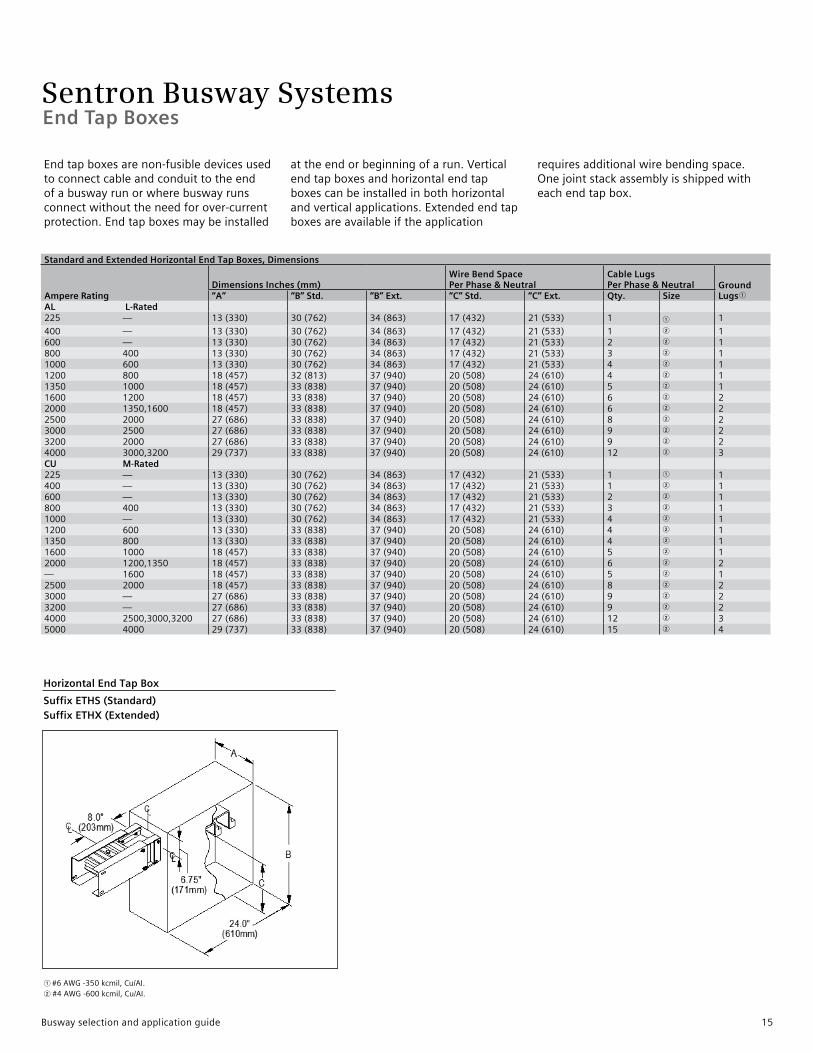
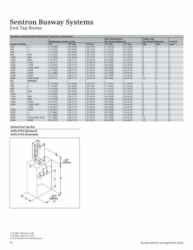
Endtapboxesarenon-fusibledevicesusedtoconnectcableandconduittotheendofabuswayrunorwherebuswayrunsconnectwithouttheneedforover-currentprotection.Endtapboxesmaybeinstalled
attheendorbeginningofarun.Verticalendtapboxesandhorizontalendtapboxescanbeinstalledinbothhorizontalandverticalapplications.Extendedendtapboxesareavailableiftheapplication
requiresadditionalwirebendingspace.Onejointstackassemblyisshippedwitheachendtapbox.
1#6AWG-350kcmil,Cu/AI.2#4AWG-600kcmil,Cu/AI.
Standard and Extended Horizontal End Tap Boxes, Dimensions
Ampere RatingDimensions Inches (mm)
Wire Bend SpacePer Phase & Neutral
Cable LugsPer Phase & Neutral Ground
Lugs1“A” “B” Std. “B” Ext. “C” Std. “C” Ext. Qty. Size AL L-Rated 225 — 13(330) 30(762) 34(863) 17(432) 21(533) 1 1 1
400 — 13(330) 30(762) 34(863) 17(432) 21(533) 1 2 1600 — 13(330) 30(762) 34(863) 17(432) 21(533) 2 2 1800 400 13(330) 30(762) 34(863) 17(432) 21(533) 3 2 11000 600 13(330) 30(762) 34(863) 17(432) 21(533) 4 2 11200 800 18(457) 32(813) 37(940) 20(508) 24(610) 4 2 11350 1000 18(457) 33(838) 37(940) 20(508) 24(610) 5 2 11600 1200 18(457) 33(838) 37(940) 20(508) 24(610) 6 2 22000 1350,1600 18(457) 33(838) 37(940) 20(508) 24(610) 6 2 22500 2000 27(686) 33(838) 37(940) 20(508) 24(610) 8 2 23000 2500 27(686) 33(838) 37(940) 20(508) 24(610) 9 2 23200 2000 27(686) 33(838) 37(940) 20(508) 24(610) 9 2 24000 3000,3200 29(737) 33(838) 37(940) 20(508) 24(610) 12 2 3CU M-Rated225 — 13(330) 30(762) 34(863) 17(432) 21(533) 1 1 1400 — 13(330) 30(762) 34(863) 17(432) 21(533) 1 2 1600 — 13(330) 30(762) 34(863) 17(432) 21(533) 2 2 1800 400 13(330) 30(762) 34(863) 17(432) 21(533) 3 2 11000 — 13(330) 30(762) 34(863) 17(432) 21(533) 4 2 11200 600 13(330) 33(838) 37(940) 20(508) 24(610) 4 2 11350 800 13(330) 33(838) 37(940) 20(508) 24(610) 4 2 11600 1000 18(457) 33(838) 37(940) 20(508) 24(610) 5 2 12000 1200,1350 18(457) 33(838) 37(940) 20(508) 24(610) 6 2 2— 1600 18(457) 33(838) 37(940) 20(508) 24(610) 5 2 12500 2000 18(457) 33(838) 37(940) 20(508) 24(610) 8 2 23000 — 27(686) 33(838) 37(940) 20(508) 24(610) 9 2 23200 — 27(686) 33(838) 37(940) 20(508) 24(610) 9 2 24000 2500,3000,3200 27(686) 33(838) 37(940) 20(508) 24(610) 12 2 35000 4000 29(737) 33(838) 37(940) 20(508) 24(610) 15 2 4
Horizontal End Tap Box
Suffix ETHS (Standard) Suffix ETHX (Extended)
Busway selection and application guide 15
Sentron Busway Systems
1#6AWG-350kcmil,Cu/AI.2#4AWG-600kcmil,Cu/AI.324.0"(610mm)forisolatedground.
Vertical End Tap Box
Suffix ETVS (Standard) Suffix ETVX (Extended)
End Tap Boxes
Standard and Extended Vertical End Tap Boxes, Dimensions
Ampere RatingDimensions Inches (mm)
Wire Bend SpacePer Phase & Neutral
Cable LugsPer Phase & Neutral Ground
Lugs 1“A” “B” Std. “B” Ext. “C” Std. “C” Ext. Qty. Size 225 — 13(330) 25(635) 29(737) 17(432) 21(533) 1 1 1400 — 13(330) 25(635) 29(737) 17(432) 21(533) 1 2 1600 — 13(330) 25(635) 29(737) 17(432) 21(533) 2 2 1800 400 13(330) 25(635) 29(737) 17(432) 21(533) 3 2 11000 600 13(330) 25(635) 29(737) 17(432) 21(533) 4 2 11200 800 18(457) 28(711) 32(813) 20(508) 24(610) 4 2 11350 1000 18(457) 28(711) 32(813) 20(508) 24(610) 4 2 11600 1200 18(457) 28(711) 32(813) 20(508) 24(610) 5 2 22000 1350,1600 18(457) 28(711) 32(813) 20(508) 24(610) 6 2 22500 2000 27(686) 28(711) 32(813) 20(508) 24(610) 8 2 23000 2500 27(686) 28(711) 32(813) 20(508) 24(610) 9 2 23200 2000 29(737) 28(711) 32(813) 20(508) 24(610) 9 2 24000 3000,3200 29(737) 28(711) 32(813) 20(508) 24(610) 12 2 3CU M-Rated225 — 13(330) 25(635) 29(737) 17(432) 21(533) 1 1 1400 — 13(330) 25(635) 29(737) 17(432) 21(533) 1 2 1600 — 13(330) 25(635) 29(737) 17(432) 21(533) 2 2 1800 400 13(330) 25(635) 29(737) 17(432) 21(533) 3 2 11000 — 13(330) 25(635) 29(737) 17(432) 21(533) 4 2 11200 600 13(330) 28(711) 32(813) 20(508) 24(610) 4 2 11350 800 13(330) 28(711) 32(813) 20(508) 24(610) 4 2 11600 1000 18(457) 28(711) 32(813) 20(508) 24(610) 5 2 12000 1200,1350 18(457) 28(711) 32(813) 20(508) 24(610) 6 2 2— 1600 18(457) 28(711) 32(813) 20(508) 24(610) 5 2 12500 2000 18(457) 28(711) 32(813) 20(508) 24(610) 8 2 23000 — 27(686) 28(711) 32(813) 20(508) 24(610) 9 2 23200 — 27(686) 28(711) 32(813) 20(508) 24(610) 9 2 24000 2500,3000,3200 27(686) 28(711) 32(813) 20(508) 24(610) 12 2 35000 4000 29(737) 28(711) 32(813) 20(508) 24(610) 15 2 4
16 Busway selection and application guide
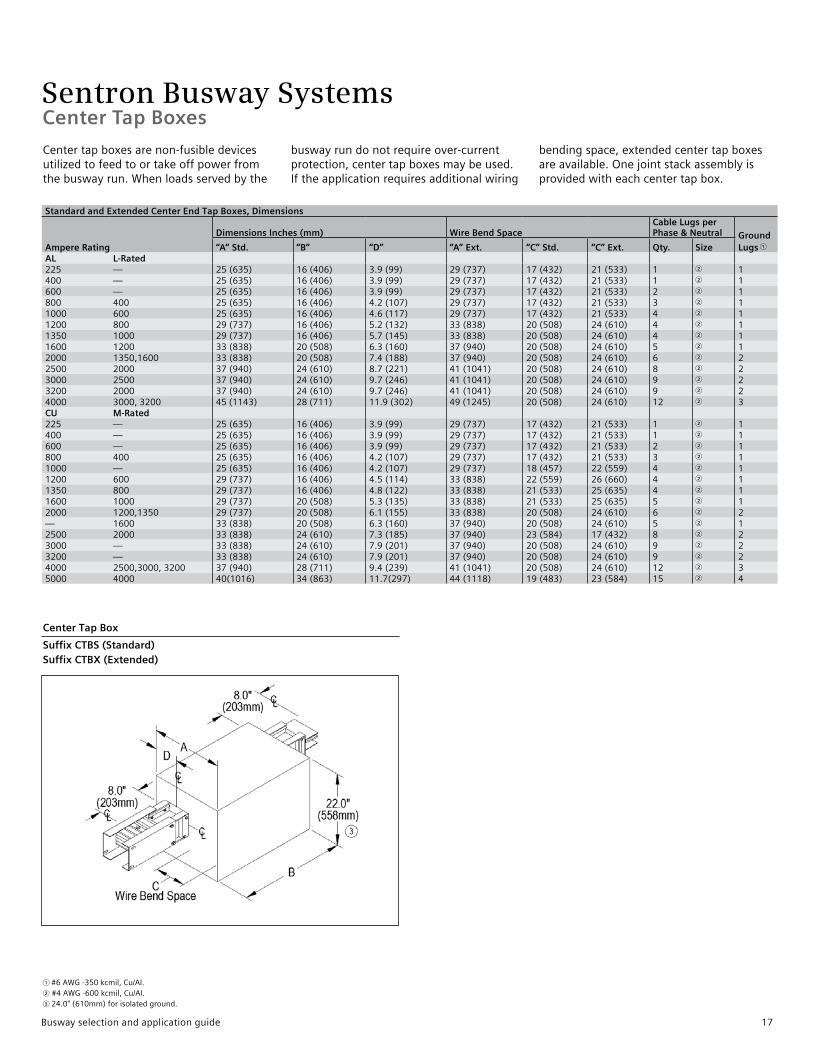
Sentron Busway SystemsCenter Tap Boxes
Standard and Extended Center End Tap Boxes, Dimensions
Ampere Rating
Dimensions Inches (mm) Wire Bend SpaceCable Lugs per Phase & Neutral Ground
Lugs 1“A” Std. “B” “D” “A” Ext. “C” Std. “C” Ext. Qty. SizeAL L-Rated 225 — 25(635) 16(406) 3.9(99) 29(737) 17(432) 21(533) 1 2 1400 — 25(635) 16(406) 3.9(99) 29(737) 17(432) 21(533) 1 2 1600 — 25(635) 16(406) 3.9(99) 29(737) 17(432) 21(533) 2 2 1800 400 25(635) 16(406) 4.2(107) 29(737) 17(432) 21(533) 3 2 11000 600 25(635) 16(406) 4.6(117) 29(737) 17(432) 21(533) 4 2 11200 800 29(737) 16(406) 5.2(132) 33(838) 20(508) 24(610) 4 2 11350 1000 29(737) 16(406) 5.7(145) 33(838) 20(508) 24(610) 4 2 11600 1200 33(838) 20(508) 6.3(160) 37(940) 20(508) 24(610) 5 2 12000 1350,1600 33(838) 20(508) 7.4(188) 37(940) 20(508) 24(610) 6 2 22500 2000 37(940) 24(610) 8.7(221) 41(1041) 20(508) 24(610) 8 2 23000 2500 37(940) 24(610) 9.7(246) 41(1041) 20(508) 24(610) 9 2 23200 2000 37(940) 24(610) 9.7(246) 41(1041) 20(508) 24(610) 9 2 24000 3000,3200 45(1143) 28(711) 11.9(302) 49(1245) 20(508) 24(610) 12 2 3CU M-Rated225 — 25(635) 16(406) 3.9(99) 29(737) 17(432) 21(533) 1 2 1400 — 25(635) 16(406) 3.9(99) 29(737) 17(432) 21(533) 1 2 1600 — 25(635) 16(406) 3.9(99) 29(737) 17(432) 21(533) 2 2 1800 400 25(635) 16(406) 4.2(107) 29(737) 17(432) 21(533) 3 2 11000 — 25(635) 16(406) 4.2(107) 29(737) 18(457) 22(559) 4 2 11200 600 29(737) 16(406) 4.5(114) 33(838) 22(559) 26(660) 4 2 11350 800 29(737) 16(406) 4.8(122) 33(838) 21(533) 25(635) 4 2 11600 1000 29(737) 20(508) 5.3(135) 33(838) 21(533) 25(635) 5 2 12000 1200,1350 29(737) 20(508) 6.1(155) 33(838) 20(508) 24(610) 6 2 2— 1600 33(838) 20(508) 6.3(160) 37(940) 20(508) 24(610) 5 2 12500 2000 33(838) 24(610) 7.3(185) 37(940) 23(584) 17(432) 8 2 23000 — 33(838) 24(610) 7.9(201) 37(940) 20(508) 24(610) 9 2 23200 — 33(838) 24(610) 7.9(201) 37(940) 20(508) 24(610) 9 2 24000 2500,3000,3200 37(940) 28(711) 9.4(239) 41(1041) 20(508) 24(610) 12 2 35000 4000 40(1016) 34(863) 11.7(297) 44(1118) 19(483) 23(584) 15 2 4
Centertapboxesarenon-fusibledevicesutilizedtofeedtoortakeoffpowerfromthebuswayrun.Whenloadsservedbythe
buswayrundonotrequireover-currentprotection,centertapboxesmaybeused.Iftheapplicationrequiresadditionalwiring
bendingspace,extendedcentertapboxesareavailable.Onejointstackassemblyisprovidedwitheachcentertapbox.
1#6AWG-350kcmil,Cu/AI.2#4AWG-600kcmil,Cu/AI.324.0"(610mm)forisolatedground.
Center Tap Box
Suffix CTBS (Standard) Suffix CTBX (Extended)
Busway selection and application guide 17
Sentron Busway SystemsIn-Line Disconnect Cubicles and Expansion Fittings
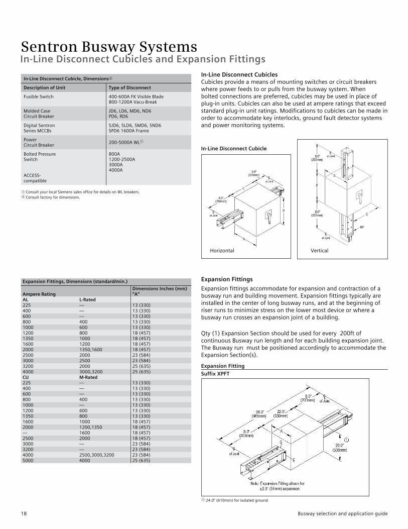
In-Line Disconnect Cubicles Cubiclesprovideameansofmountingswitchesorcircuitbreakerswherepowerfeedstoorpullsfromthebuswaysystem.Whenboltedconnectionsarepreferred,cubiclesmaybeusedinplaceofplug-inunits.Cubiclescanalsobeusedatampereratingsthatexceedstandardplug-inunitratings.Modificationstocubiclescanbemadeinordertoaccommodatekeyinterlocks,groundfaultdetectorsystemsandpowermonitoringsystems.
Expansion Fittings
Expansionfittingsaccommodateforexpansionandcontractionofabuswayrunandbuildingmovement.Expansionfittingstypicallyareinstalledinthecenteroflongbuswayruns,andatthebeginningofriserrunstominimizestressonthelowermostdeviceorwhereabuswayruncrossesanexpansionjointofabuilding.
Qty(1)ExpansionSectionshouldbeusedforevery200ftofcontinuousBuswayrunlengthandforeachbuildingexpansionjoint.TheBuswayrunmustbepositionedaccordinglytoaccommodatetheExpansionSection(s).
In-Line Disconnect Cubicle
Expansion Fitting
Suffix XPFT
In-Line Disconnect Cubicle, Dimensions 2
Description of Unit Type of Disconnect
FusibleSwitch 400-600AFKVisibleBlade800-1200AVacu-Break
MoldedCaseCircuitBreaker
JD6,LD6,MD6,ND6PD6,RD6
DigitalSentronSeriesMCCBs
SJD6,SLD6,SMD6,SND6SPD61600AFrame
PowerCircuitBreaker
200-5000AWL1
BoltedPressureSwitch
ACCESS-compatible
800A1200-2500A3000A4000A
Expansion Fittings, Dimensions (standard/min.)
Ampere RatingDimensions Inches (mm)“A”
AL L-Rated225 — 13(330)400 — 13(330)600 — 13(330)800 400 13(330)1000 600 13(330)1200 800 18(457)1350 1000 18(457)1600 1200 18(457)2000 1350,1600 18(457)2500 2000 23(584)3000 2500 23(584)3200 2000 25(635)4000 3000,3200 25(635)CU M-Rated225 — 13(330)400 — 13(330)600 — 13(330)800 400 13(330)1000 — 13(330)1200 600 13(330)1350 800 13(330)1600 1000 18(457)2000 1200,1350 18(457)— 1600 18(457)2500 2000 18(457)3000 — 23(584)3200 — 23(584)4000 2500,3000,3200 23(584)5000 4000 25(635)
124.0"(610mm)forisolatedground.
1ConsultyourlocalSiemenssalesofficefordetailsonWLbreakers.2Consultfactoryfordimensions.
Horizontal Vertical
18 Busway selection and application guide
Sentron Busway SystemsReducers and Phase Rotation Fittings
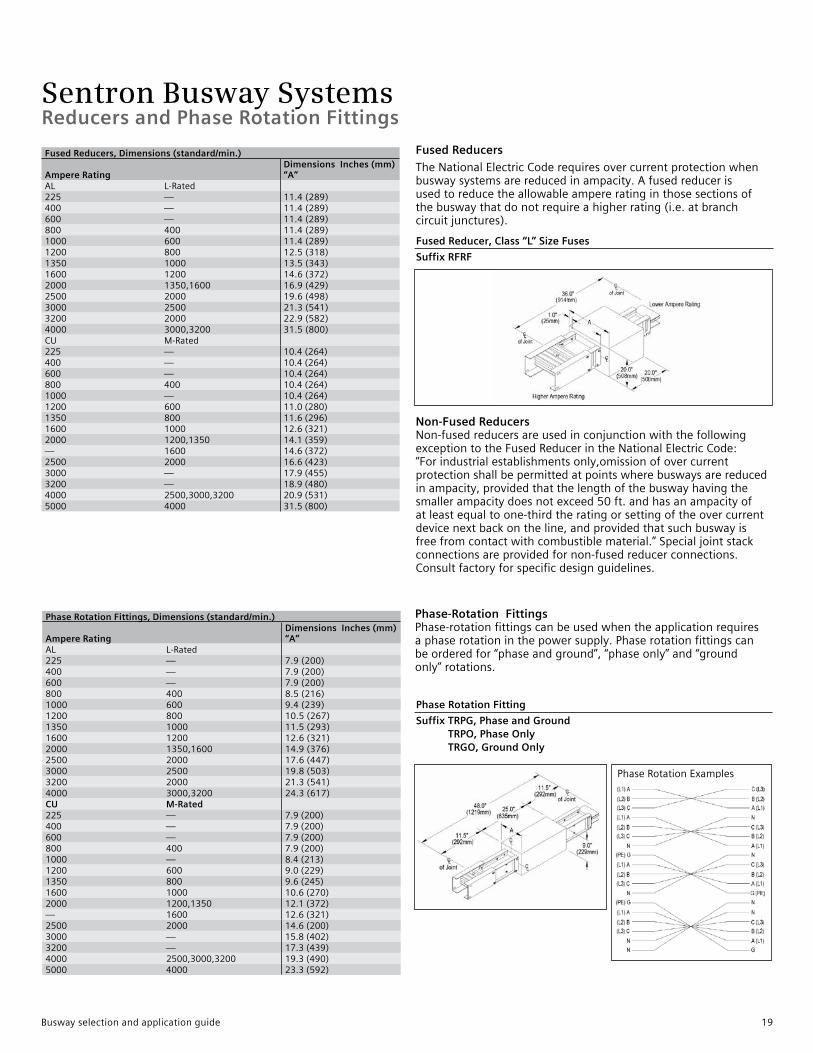
Fused Reducers
TheNationalElectricCoderequiresovercurrentprotectionwhenbuswaysystemsarereducedinampacity.Afusedreducerisusedtoreducetheallowableampereratinginthosesectionsofthebuswaythatdonotrequireahigherrating(i.e.atbranchcircuitjunctures).
Non-Fused Reducers Non-fusedreducersareusedinconjunctionwiththefollowingexceptiontotheFusedReducerintheNationalElectricCode:“Forindustrialestablishmentsonly,omissionofovercurrentprotectionshallbepermittedatpointswherebuswaysarereducedinampacity,providedthatthelengthofthebuswayhavingthesmallerampacitydoesnotexceed50ft.andhasanampacityofatleastequaltoone-thirdtheratingorsettingoftheovercurrentdevicenextbackontheline,andprovidedthatsuchbuswayisfreefromcontactwithcombustiblematerial.”Specialjointstackconnectionsareprovidedfornon-fusedreducerconnections.Consultfactoryforspecificdesignguidelines.
Phase-Rotation Fittings Phase-rotationfittingscanbeusedwhentheapplicationrequiresaphaserotationinthepowersupply.Phaserotationfittingscanbeorderedfor“phaseandground”,“phaseonly”and“groundonly”rotations.
Fused Reducer, Class “L” Size Fuses
Suffix RFRF
Phase Rotation Fitting
Suffix TRPG, Phase and Ground TRPO, Phase Only TRGO, Ground Only
Phase Rotation Fittings, Dimensions (standard/min.)
Ampere RatingDimensions Inches (mm)“A”
AL L-Rated225 — 7.9(200)400 — 7.9(200)600 — 7.9(200)800 400 8.5(216)1000 600 9.4(239)1200 800 10.5(267)1350 1000 11.5(293)1600 1200 12.6(321)2000 1350,1600 14.9(376)2500 2000 17.6(447)3000 2500 19.8(503)3200 2000 21.3(541)4000 3000,3200 24.3(617)CU M-Rated225 — 7.9(200)400 — 7.9(200)600 — 7.9(200)800 400 7.9(200)1000 — 8.4(213)1200 600 9.0(229)1350 800 9.6(245)1600 1000 10.6(270)2000 1200,1350 12.1(372)— 1600 12.6(321)2500 2000 14.6(200)3000 — 15.8(402)3200 — 17.3(439)4000 2500,3000,3200 19.3(490)5000 4000 23.3(592)
PhaseRotationExamples
Fused Reducers, Dimensions (standard/min.)
Ampere RatingDimensions Inches (mm)“A”
AL L-Rated225 — 11.4(289)400 — 11.4(289)600 — 11.4(289)800 400 11.4(289)1000 600 11.4(289)1200 800 12.5(318)1350 1000 13.5(343)1600 1200 14.6(372)2000 1350,1600 16.9(429)2500 2000 19.6(498)3000 2500 21.3(541)3200 2000 22.9(582)4000 3000,3200 31.5(800)CU M-Rated225 — 10.4(264)400 — 10.4(264)600 — 10.4(264)800 400 10.4(264)1000 — 10.4(264)1200 600 11.0(280)1350 800 11.6(296)1600 1000 12.6(321)2000 1200,1350 14.1(359)— 1600 14.6(372)2500 2000 16.6(423)3000 — 17.9(455)3200 — 18.9(480)4000 2500,3000,3200 20.9(531)5000 4000 31.5(800)
Busway selection and application guide 19

Sentron Busway Systems
1 #6AWG-350kcmil,Cu/Al.2#4AWG-600kcmil,Cu/Al.
Single-Phase Service Heads, Dimensions (standard/min.)
Ampere Rating
Dimensions Inches (mm)
Cable Lugs perPhase and Neutral Ground
Lugs 1Single-Phase “A” Qty. SizeAL L-Rated225 — 13(330) 1 1 1400 225 13(330) 1 2 1600 — 13(330) 2 2 1800 400 13(330) 3 2 11000 600 13(330) 4 2 11200 800 18(457) 4 2 11350 1000 18(457) 4 2 11600 1200 18(457) 5 2 12000 1350,1600 20(508) 6 2 22500 2000 27(686) 8 2 23000 2500 29(737) 9 2 23200 2000 29(737) 9 2 24000 3000,3200 29(737) 12 2 3CU M-Rated225 — 13(330) 1 1 1400 — 13(330) 1 2 1600 — 13(330) 2 2 1800 400 13(330) 3 2 11000 — 13(330) 4 2 11200 600 13(330) 4 2 11350 800 13(330) 4 2 11600 1000 18(457) 5 2 12000 1200,1350 20(508) 6 2 2— 1600 18(457) 5 2 12500 2000 20(508) 8 2 23000 — 27(686) 9 2 23200 — 27(686) 9 2 24000 2500,3000,3200 27(686) 12 2 35000 4000 29(737) 15 2 4
ServiceHeadsareusedtoconnectbuswaytoaserviceentrance.IntheSentronBuswayline,3single-phaseserviceheadsand3-phaseserviceheadconnectionsareavailable.Thestandardserviceentranceconnectionisthe3-phaseserviceheadwhichconsistsofoneserviceheadforallthreephases.3single-phaseserviceheadsconsistofthreeheads–oneforeachphaseandmaybeusedto
meettherequirementsofcertainapplications.Toensureeaseofinstallationofincomingcables,bothtypesofSentronserviceheadsareconstructedsothatthelugsfacetheGlasticbottomofthebox.TheGlasticbottomprovidesinsulationandprotectiontotheincomingcables.
Three Single-Phase Service Heads
Suffix V1TX
Service Heads
20 Busway selection and application guide

Sentron Busway Systems
1#6AWG-350kcmil,Cu/Al.2 #4AWG-600kcmil,Cu/Al.
Three-Phase Service Heads, Dimensions (standard/min.)
Ampere Rating
Dimensions Inches (mm)
Cable Lugs perPhase and Neutral Ground
Lugs 1Three-Phase BA” Qty. SizeAL L-Rated225 — 13(330) 1 1 1400 225 13(330) 1 2 1600 — 13(330) 2 2 1800 400 13(330) 3 2 11000 600 13(330) 4 2 11200 800 18(457) 4 2 11350 1000 18(457) 4 2 11600 1200 18(457) 5 2 12000 1350,1600 18(457) 6 2 22500 2000 27(686) 8 2 23000 2500 27(686) 9 2 23200 2000 27(686) 9 2 24000 3000,3200 29(737) 12 2 3CU M-Rated225 — 13(330) 1 1 1400 — 13(330) 1 2 1600 — 13(330) 2 2 1800 400 13(330) 3 2 11000 — 13(330) 4 2 11200 600 13(330) 4 2 11350 800 13(330) 4 2 11600 1000 18(457) 5 2 12000 1200,1350 18(457) 6 2 2— 1600 18(457) 5 2 12500 2000 18(457) 8 2 23000 — 27(686) 9 2 23200 — 27(686) 9 2 24000 2500,3000,3200 27(686) 12 2 35000 4000 29(737) 15 2 4
Three-Phase Service Head
Suffix V3TX
Service Heads
Busway selection and application guide 21
Sentron Busway SystemsHangers
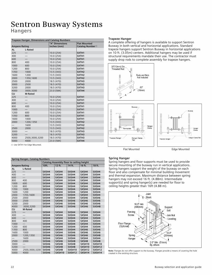
Trapeze Hanger AcompleteofferingofhangersisavailabletosupportSentronBuswayinbothverticalandhorizontalapplications.StandardtrapezehangerssupportSentronBuswayinhorizontalapplicationson10ft.(3.05m)centers.Additionalhangersmaybeusedifstructuralrequirementsmandatetheiruse.Thecontractormustsupplydroprodstocompleteassemblyfortrapezehangers.
Spring Hanger, Catalog Numbers
Ampere RatingCatalog Assembly floor to ceiling height10ft. 12 ft. 14 ft. 16 ft. 18 ft.
AL L-Rated225 — SXSH4 SXSH4 SXSH4 SXSH4 SXSH4400 — SXSH4 SXSH4 SXSH4 SXSH4 SXSH4600 — SXSH4 SXSH4 SXSH4 SXSH4 SXSH4800 400 SXSH4 SXSH4 SXSH4 SXSH4 SXSH41000 600 SXSH4 SXSH4 SXSH4 SXSH4 SXSH41200 800 SXSH4 SXSH4 SXSH4 SXSH4 SXSH41350 1000 SXSH4 SXSH4 SXSH4 SXSH4 SXSH41600 1200 SXSH4 SXSH4 SXSH4 SXSH4 SXSH42000 1350,1600 SXSH4 SXSH4 SXSH4 SXSH4 SXSH42500 2000 SXSH4 SXSH4 SXSH4 SXSH6 SXSH63000 2500 SXSH4 SXSH6 SXSH6 SXSH6 SXSH63200 2000 SXSH4 SXSH6 SXSH6 SXSH6 SXSH64000 3000,3200 SXSH4 SXSH6 SXSH6 SXSH6 SXSH8CU M-Rated225 — SXSH4 SXSH4 SXSH4 SXSH4 SXSH4400 — SXSH4 SXSH4 SXSH4 SXSH4 SXSH4600 — SXSH4 SXSH4 SXSH4 SXSH4 SXSH4800 400 SXSH4 SXSH4 SXSH4 SXSH4 SXSH41000 — SXSH4 SXSH4 SXSH4 SXSH4 SXSH41200 600 SXSH4 SXSH4 SXSH4 SXSH4 SXSH41350 800 SXSH4 SXSH4 SXSH4 SXSH6 SXSH61600 1000 SXSH4 SXSH4 SXSH6 SXSH6 SXSH62000 1200,1350 SXSH6 SXSH6 SXSH6 SXSH6 SXSH8— 1600 SXSH4 SXSH4 SXSH4 SXSH4 SXSH42500 2000 SXSH6 SXSH6 SXSH8 SXSH8 SXSH83000 — SXSH6 SXSH8 SXSH8 SXSH10 SXSH103200 — SXSH6 SXSH8 SXSH8 SXSH10 SXSH124000 2500,3000,3200 SXSH6 SXSH8 SXSH10 SXSH12 SXSH125000 4000 SXSH6 SXSH10 SXSH12 SXSH14 SXSH14
Trapeze Hanger, Dimensions and Catalog Numbers
Ampere Rating“A” Dimensionsinches (mm)
Flat MountedCatalog Number 1
AL L-Rated225 — 10.0(254) SXTH1400 — 10.0(254) SXTH1600 — 10.0(254) SXTH1800 400 10.0(254) SXTH11000 600 10.0(254) SXTH11200 800 10.0(254) SXTH11350 1000 13.5(343) SXTH21600 1200 13.5(343) SXTH22000 1350,1600 13.5(343) SXTH22500 2000 18.5(470) SXTH33000 2500 18.5(470) SXTH33200 2000 18.5(470) SXTH34000 3000,3200 23.0(584) SXTH4CU M-Rated225 — 10.0(254) SXTH1400 — 10.0(254) SXTH1600 — 10.0(254) SXTH1800 400 10.0(254) SXTH11000 — 10.0(254) SXTH11200 600 10.0(254) SXTH11350 800 10.0(254) SXTH11600 1000 10.0(254) SXTH12000 1200,1350 13.5(343) SXTH2— 1600 13.5(343) SXTH22500 2000 13.5(343) SXTH23000 — 18.5(470) SXTH33200 — 18.5(470) SXTH34000 2500,3000,3200 18.5(470) SXTH35000 4000 23.0(584) SXTH4
Spring Hanger Springhangersandfloorsupportsmustbeusedtoprovidesecuremountingofthebuswayruninverticalapplications.Springhangerssupporttheweightofthebuswayoneachfloorandalsocompensateforminimalbuildingmovementandthermalexpansion.Maximumdistancebetweenspringhangersmaynotexceed16ft.(4.88m).Intermediatesupport(s)andspringhanger(s)areneededforfloortoceilingheightsgreaterthan16ft(4.88m).
1 UseSXTH1forEdgeMounted.
Note:Flangesdonotoffersupporttothebusway.Flangesprovideameansofcoveringtheholecreatedintheexistingstructure.
FlatMounted EdgeMounted
22 Busway selection and application guide
Sentron Busway SystemsHangers
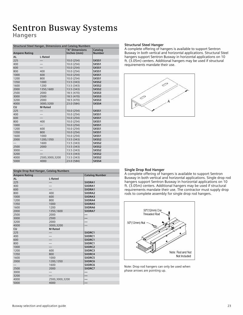
Single Drop Rod Hanger, Catalog Numbers
Ampere Rating Catalog NumberAL L-Rated225 — SXDRA1400 — SXDRA1600 — SXDRA1800 400 SXDRA21000 600 SXDRA31200 800 SXDRA41350 1000 SXDRA51600 1200 SXDRA62000 1350,1600 SXDRA72500 2000 —3000 2500 —3200 2000 —4000 3000,3200 —CU M-Rated225 — SXDRC1400 — SXDRC1600 — SXDRC1800 — SXDRC11000 — SXDRC21200 600 SXDRC31350 800 SXDRC41600 1000 SXDRC52000 1200,1350 SXDRC6— 1600 SXDRC62500 2000 SXDRC73000 — —3200 — —4000 2500,3000,3200 —5000 4000 —
Structural Steel Hanger AcompleteofferingofhangersisavailabletosupportSentronBuswayinbothverticalandhorizontalapplications.StructuralSteelhangerssupportSentronBuswayinhorizontalapplicationson10ft.(3.05m)centers.Additionalhangersmaybeusedifstructuralrequirementsmandatetheiruse.
Single Drop Rod HangerAcompleteofferingofhangersisavailabletosupportSentronBuswayinbothverticalandhorizontalapplications.SingledroprodhangerssupportSentronBuswayinhorizontalapplicationson10ft.(3.05m)centers.Additionalhangersmaybeusedifstructuralrequirementsmandatetheiruse.Thecontractormustsupplydroprodstocompleteassemblyforsingledroprodhangers.
Structural Steel Hanger, Dimensions and Catalog Numbers
Ampere Rating“A” DimensionsInches (mm)
CatalogNumber
AL L-Rated225 — 10.0(254) SXSS1400 — 10.0(254) SXSS1600 — 10.0(254) SXSS1800 400 10.0(254) SXSS11000 600 10.0(254) SXSS11200 800 10.0(254) SXSS11350 1000 13.5(343) SXSS21600 1200 13.5(343) SXSS22000 1350,1600 13.5(343) SXSS22500 2000 18.5(470) SXSS33000 2500 18.5(470) SXSS33200 2000 18.5(470) SXSS34000 3000,3200 23.0(584) SXSS4CU M-Rated225 — 10.0(254) SXSS1400 — 10.0(254) SXSS1600 — 10.0(254) SXSS1800 400 10.0(254) SXSS11000 — 10.0(254) SXSS11200 600 10.0(254) SXSS11350 800 10.0(254) SXSS11600 1000 10.0(254) SXSS12000 1200,1350 13.5(343) SXSS2— 1600 13.5(343) SXSS22500 2000 13.5(343) SXSS23000 — 13.5(343) SXSS23200 — 13.5(343) SXSS24000 2500,3000,3200 13.5(343) SXSS25000 4000 23.0(584) SXSS4
Note:Droprodhangerscanonlybeusedwhenphasearrowsarepointingup.
Busway selection and application guide 23

Sentron Busway Systems
End Closers Endcloserssafelyterminateabuswayrunandprotectthebusbarends.Endclosersmayberemovedeasilyinordertoextendabuswayrun.EndclosersareshippedwithGlasticinsulationpieces,however,jointstacksandinspectioncoversarenotincluded.
Wall Mounted Hanger WallMountedHangersareusedforhorizontalapplicationsclosetoawall.Thebuswaycanbemountedeitheredgewiseorflatwisetothewall.
WallMountedHangerensurestheminimumclearancebetweenthewallandthebuswayrun.
End Closers
(Joint stack and covers not included)Suffix ECLS
Wall Mounted Hanger, Dimensions and Catalog Numbers
Ampere Rating
Dimensions Inches (mm) CatalogNumber“A” ”B” ”C”
AL L-Rated225 — 12.3(311) 6.1(156) 4.2(107) SXWH1400 — 12.3(311) 6.1(156) 4.2(107) SXWH1600 — 12.3(311) 6.1(156) 4.2(107) SXWH1800 400 12.3(311) 6.1(156) 3.8(97) SXWH11000 600 12.3(311) 6.1(156) 3.8(97) SXWH11200 800 12.3(311) 6.1(156) 2.8(72) SXWH11350 1000 16.3(413) 8.1(206) 4.4(111) SXWH21600 1200 16.3(413) 8.1(206) 3.9(98) SXWH22000 1350,1600 16.3(413) 8.1(206) 2.8(70) SXWH22500 2000 20.8(527) 10.4(264) 3.6(92) SXWH33000 2500 20.8(527) 10.4(264) 2.5(64) SXWH33200 2000 20.8(527) 10.4(264) 1.8(46) SXWH34000 3000,3200 25.3(641) 12.6(321) 2.5(64) SXWH4 CU M-Rated
225 — 12.3(311) 6.1(156) 4.2(107) SXWH1400 — 12.3(311) 6.1(156) 4.2(107) SXWH1600 — 12.3(311) 6.1(156) 4.2(107) SXWH1800 400 12.3(311) 6.1(156) 3.8(97) SXWH11000 — 12.3(311) 6.1(156) 3.8(97) SXWH11200 600 12.3(311) 6.1(156) 2.8(72) SXWH11350 800 12.3(311) 6.1(156) 2.8(72) SXWH11600 1000 12.3(311) 6.1(156) 2.8(72) SXWH12000 1200,1350 16.3(413) 8.1(206) 4.4(111) SXWH2— 1600 16.3(413) 8.1(206) 3.9(98) SXWH22500 2000 16.3(413) 8.1(206) 2.8(70) SXWH23000 — 20.8(527) 10.4(264) 3.6(92) SXWH33200 — 20.8(527) 10.4(264) 2.5(64) SXWH34000 2500,3000,3200 20.8(527) 10.4(264) 1.8(46) SXWH35000 4000 25.3(641) 12.6(321) 2.5(64) SXWH4
Hangers and End Closers
24 Busway selection and application guide
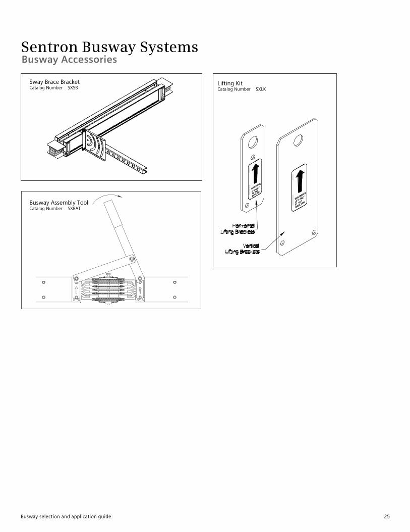
Sentron Busway SystemsBusway Accessories
BuswayAssemblyToolCatalogNumber SXBAT
LiftingKitCatalogNumber SXLK
SwayBraceBracketCatalogNumber SXSB
Busway selection and application guide 25
Sentron Busway Systems
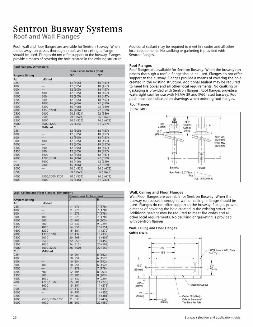
Wall, Ceiling and Floor Flanges, Dimensions
Ampere RatingDimensions Inches (mm)A B
AL L-Rated225 — 11(279) 7(178)400 — 11(279) 7(178)600 — 11(279) 7(178)800 400 11(279) 7(178)1000 600 12(305) 8(203)1200 800 13(330) 9(229)1350 1000 14(356) 10(254)1600 1200 15(381) 11(279)2000 1350,1600 17(432) 13(330)2500 2000 20(508) 16(406)3000 2500 22(559) 18(457)3200 2000 24(610) 20(508)4000 3000,3200 26(660) 22(559)CU M-Rated225 — 10(254) 6(152)400 — 10(254) 6(152)600 — 10(254) 6(152)800 400 10(254) 6(152)1000 — 11(279) 7(178)1200 600 12(305) 8(203)1350 800 12(305) 8(203)1600 1000 13(330) 9(229)2000 1200,1350 15(381) 11(279)— 1600 15(381) 11(279)2500 2000 17(432) 13(330)3000 — 18(457) 14(356)3200 — 19(483) 15(381)4000 2500,3000,3200 21(533) 17(432)5000 4000 26(660) 22(559)
Wall, Ceiling and Floor Flanges
Suffix GWFL
Wall, Ceiling and Floor Flanges Wall/FloorflangesareavailableforSentronBusway.Whenthebuswayrunpassesthoroughawallorceiling,aflangeshouldbeused.Flangesdonotoffersupporttothebusway.Flangesprovideameansofcoveringtheholecreatedintheexistingstructure.Additionalsealantmayberequiredtomeetfirecodesandallotherlocalrequirements.NocaulkingorgasketingisprovidedwithSentronflanges.
Roof Flanges
Suffix GRFL
Roof Flanges RoofflangesareavailableforSentronBusway.Whenthebuswayrunpassesthorougharoof,aflangeshouldbeused.Flangesdonotoffersupporttothebusway.Flangesprovideameansofcoveringtheholecreatedintheexistingstructure.Additionalsealantmayberequiredtomeetfirecodesandallotherlocalrequirements.NocaulkingorgasketingisprovidedwithSentronflanges.RoofflangesprovideawatertightsealforusewithNEMA3RandIP66ratedbusway.Roofpitchmustbeindicatedondrawingswhenorderingroofflanges.
Roof Flanges, Dimensions
Ampere Rating
Dimensions Inches (mm)
“A” ”B”AL L-Rated225 — 12(305) 18(457)400 — 12(305) 18(457)600 — 12(305) 18(457)800 400 12(305) 18(457)1000 600 12(305) 18(457)1200 800 12(305) 18(457)1350 1000 16(406) 22(559)1600 1200 16(406) 22(559)2000 1350,1600 16(406) 22(559)2500 2000 20.5(521) 22(559)3000 2500 20.5(521) 26.5(673)3200 2000 20.5(521) 26.5(673)4000 3000,3200 25(635) 31(787)CU M-Rated225 — 12(305) 18(457)400 — 12(305) 18(457)600 — 12(305) 18(457)800 400 12(305) 18(457)1000 — 12(305) 18(457))1200 600 12(305) 18(457)1350 800 12(305) 18(457)1600 1000 12(305) 18(457)2000 1200,1350 16(406) 22(559)— 1600 16(406) 22(559)2500 2000 16(406) 22(559)3000 — 20.5(521) 26.5(673)3200 — 20.5(521) 26.5(673)
4000 2500,3000,3200 20.5(521) 26.5(673)5000 4000 25(635) 31(787)
Roof,wallandfloorflangesareavailableforSentronBusway.Whenthebuswayrunpassesthorougharoof,wallorceiling,aflangeshouldbeused.Flangesdonotoffersupporttothebusway.Flangesprovideameansofcoveringtheholecreatedintheexistingstructure.
Additionalsealantmayberequiredtomeetfirecodesandallotherlocalrequirements.NocaulkingorgasketingisprovidedwithSentronflanges.
Roof and Wall Flanges
26 Busway selection and application guide
Sentron Busway Systems
Wall, Ceiling and Floor Flanges Wall/FloorflangesareavailableforSentronBusway.Whenthebuswayrunpassesthoroughawallorceiling,aflangeshouldbeused.Flangesdonotoffersupporttothebusway.Flangesprovideameansofcoveringtheholecreatedintheexistingstructure.Additionalsealantmayberequiredtomeetfirecodesandallotherlocalrequirements.NocaulkingorgasketingisprovidedwithSentronflanges.
Roof Flanges RoofflangesareavailableforSentronBusway.Whenthebuswayrunpassesthorougharoof,aflangeshouldbeused.Flangesdonotoffersupporttothebusway.Flangesprovideameansofcoveringtheholecreatedintheexistingstructure.Additionalsealantmayberequiredtomeetfirecodesandallotherlocalrequirements.NocaulkingorgasketingisprovidedwithSentronflanges.RoofflangesprovideawatertightsealforusewithNEMA3RandIP66ratedbusway.Roofpitchmustbeindicatedondrawingswhenorderingroofflanges.
Flanged Ends
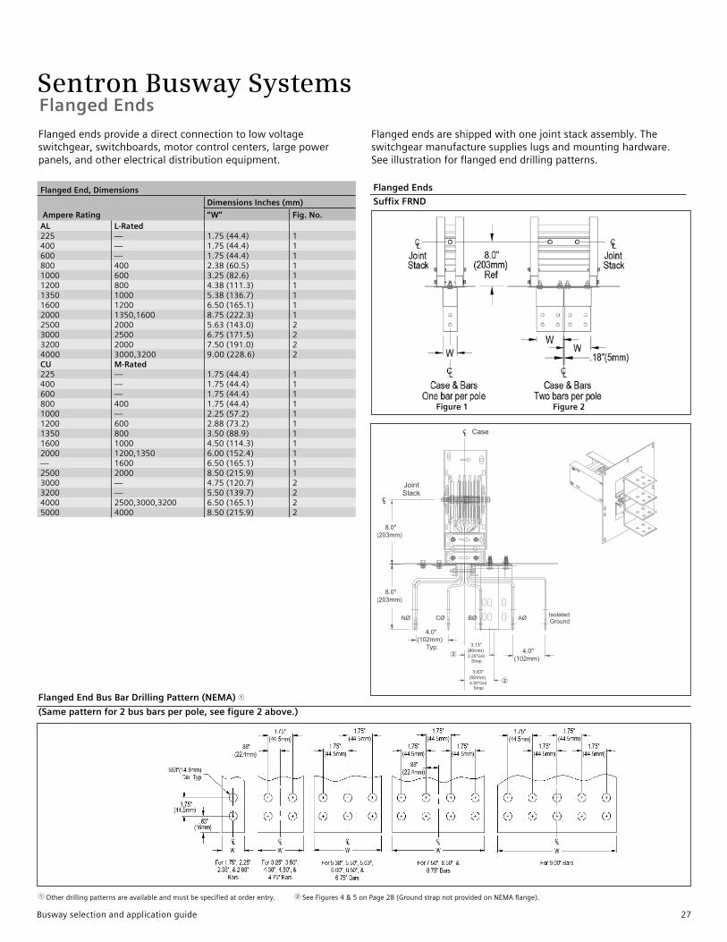
Flanged End Bus Bar Drilling Pattern (NEMA) 1
(Same pattern for 2 bus bars per pole, see figure 2 above.)
1 Otherdrillingpatternsareavailableandmustbespecifiedatorderentry.2 SeeFigures4&5onPage28(GroundstrapnotprovidedonNEMAflange).
Flanged End, Dimensions
Ampere Rating
Dimensions Inches (mm)
“W” Fig. No.AL L-Rated225 — 1.75(44.4) 1400 — 1.75(44.4) 1600 — 1.75(44.4) 1800 400 2.38(60.5) 11000 600 3.25(82.6) 11200 800 4.38(111.3) 11350 1000 5.38(136.7) 11600 1200 6.50(165.1) 12000 1350,1600 8.75(222.3) 12500 2000 5.63(143.0) 23000 2500 6.75(171.5) 23200 2000 7.50(191.0) 24000 3000,3200 9.00(228.6) 2CU M-Rated225 — 1.75(44.4) 1400 — 1.75(44.4) 1600 — 1.75(44.4) 1800 400 1.75(44.4) 11000 — 2.25(57.2) 11200 600 2.88(73.2) 11350 800 3.50(88.9) 11600 1000 4.50(114.3) 12000 1200,1350 6.00(152.4) 1— 1600 6.50(165.1) 12500 2000 8.50(215.9) 13000 — 4.75(120.7) 23200 — 5.50(139.7) 24000 2500,3000,3200 6.50(165.1) 25000 4000 8.50(215.9) 2
Figure 1 Figure 2
Flangedendsprovideadirectconnectiontolowvoltageswitchgear,switchboards,motorcontrolcenters,largepowerpanels,andotherelectricaldistributionequipment.
Flangedendsareshippedwithonejointstackassembly.Theswitchgearmanufacturesupplieslugsandmountinghardware.Seeillustrationforflangedenddrillingpatterns.
Flanged Ends
Suffix FRND
CL
CL
8.0"
(203mm)
8.0"
(203mm)
4.0"
(102mm)
Typ.4.0"
(102mm)
3.13"
(80mm)2.25"Grd
Strap
3.63"
(92mm)4.50"Grd
Strap
NØ CØ AØBØIsolatedGround
Joint Stack
Case
CL
CL
8.0"
(203mm)
8.0"
(203mm)
4.0"
(102mm)
Typ.4.0"
(102mm)
3.13"
(80mm)2.25"Grd
Strap
3.63"
(92mm)4.50"Grd
Strap
NØ CØ AØBØIsolatedGround
Joint Stack
Case
2
2
Busway selection and application guide 27

Sentron Busway Systems
Flanged End, Dimensions (standard/min.)
Ampere RatingDimensions Inches (mm)Ref. Bar Width Fig. No. “A” ”B” ”C” ”D” ”E” ”F” ”G” Fig. No.
AL L-Rated225 — 2.38(60.5) 1 10.0(254) 8.00(203) 4.38(111) 1.94(49) 3.88(99) — 6.00(152) 4,5400 — 2.38(60.5) 1 10.0(254) 8.00(203) 4.38(111) 1.94(49) 3.88(99) — 6.00(152) 4,5600 — 2.38(60.5) 1 10.0(254) 8.00(203) 4.38(111) 1.94(49) 3.88(99) — 6.00(152) 4,5800 400 2.38(60.5) 1 10.0(254) 8.00(203) 4.38(111) 1.94(49) 3.88(99) — 6.00(152) 4,51000 600 3.25(82.6) 2 10.0(254) 8.00(203) 4.38(111) 1.94(49) 2.06(52) — 6.00(152) 4,61200 800 4.38(111.3) 2 15.50(395) 13.50(343) 7.13(181) 1.60(41) 3.19(81) — 8.50(216) 4,61350 1000 5.38(136.7) 2 15.50(395) 13.50(343) 7.13(181) 2.10(53) 4.19(106) — 8.50(216) 4,61600 1200 6.50(165.1) 2 15.50(395) 13.50(343) 7.13(181) 2.66(67) 5.31(135) — 8.50(216) 4,62000 1350,1600 8.75(222.3) 2 15.50(395) 13.50(343) 7.13(181) 3.78(96) 7.56(192) — 8.50(216) 4,62500 2000 5.63(143.0) 3 20.0(508) 18.00(457) 4.50(114) 0.68(17) 1.37(36) 4.44(113) 13.25(337) 4,63000 2500 6.75(171.5) 3 20.0(508) 18.00(457) 4.50(114) 0.68(17) 1.37(36) 5.56(141) 13.25(337) 4,63200 2000 7.50(190.5) 3 24.0(610) 22.0(569) 5.50(140) 0.68(17) 1.37(36) 6.32(161) 13.25(337) 4,64000 3000,3200 9.00(228.6) 3 24.0(610) 22.0(569) 5.50(140) 0.68(17) 1.37(36) 7.81(198) 14.25(362) 4,6CU M-Rated225 — 1.75(44.4) 1 10.0(254) 8.00(203) 4.38(111) 1.63(41) 3.25(83) — 6.00(152) 4,5400 — 1.75(44.4) 1 10.0(254) 8.00(203) 4.38(111) 1.63(41) 3.25(83) — 6.00(152) 4,5600 — 1.75(44.4) 1 10.0(254) 8.00(203) 4.38(111) 1.63(41) 3.25(83) — 6.00(152) 4,5800 400 1.75(44.4) 1 10.0(254) 8.00(203) 4.38(111) 1.63(41) 3.25(83) — 6.00(152) 4,51000 — 2.25(57.2) 1 10.0(254) 8.00(203) 4.38(111) 1.88(48) 3.75(95) — 6.00(152) 4,51200 600 2.88(73.2) 2 10.0(254) 8.00(203) 4.38(111) 0.85(21) 1.69(43) — 6.00(152) 4,61350 800 3.50(88.9) 2 10.0(254) 8.00(203) 4.38(111) 1.16(29) 2.31(59) — 6.00(152) 4,61600 1000 4.50(114.3) 2 15.50(395) 13.50(343) 7.13(181) 1.66(42) 3.31(84) — 8.50(216) 4,62000 1200,1350 6.00(152.4) 2 15.50(395) 13.50(343) 7.13(181) 2.41(42) 4.81(122) — 8.50(216) 4,6— 1600 6.50(165.1) 2 15.50(395) 13.50(343) 7.13(181) 2.66(67) 5.31(135) — 8.50(216) 4,62500 2000 8.50(215.9) 1 15.50(395) 13.50(343) 7.13(181) 3.66(93) 7.31(186) — 8.50(216) 4,63000 — 4.75(120.7) 3 20.0(508) 18.00(457) 4.50(114) 0.68(17) 1.37(36) 3.56(90) 13.25(337) 4,63200 — 5.50(139.7) 3 20.0(508) 18.00(457) 4.50(114) 0.68(17) 1.37(36) 4.32(110) 13.25(337) 4,64000 2500,3000,3200 6.50(165.1) 3 20.0(508) 18.00(457) 4.50(114) 0.68(17) 1.37(36) 5.31(135) 13.25(337) 4,65000 4000 8.50(215.9) 3 24.0(610) 22.00(569) 5.50(140) 0.68(17) 1.37(36) 7.31(186) 14.25(362) 4,6
Integral and Internal Ground Strap Drilling Detail
Figure 1 Figure 3Figure 2
Figure 4 Figure 5 Figure 6
Flanged Ends
1 Add4.0”(102mm)forisolatedgroundapplications. 1 Add4.0”(102mm)forisolatedgroundapplications.
28 Busway selection and application guide
Sentron Busway SystemsPanelboards and Meter Center Modules
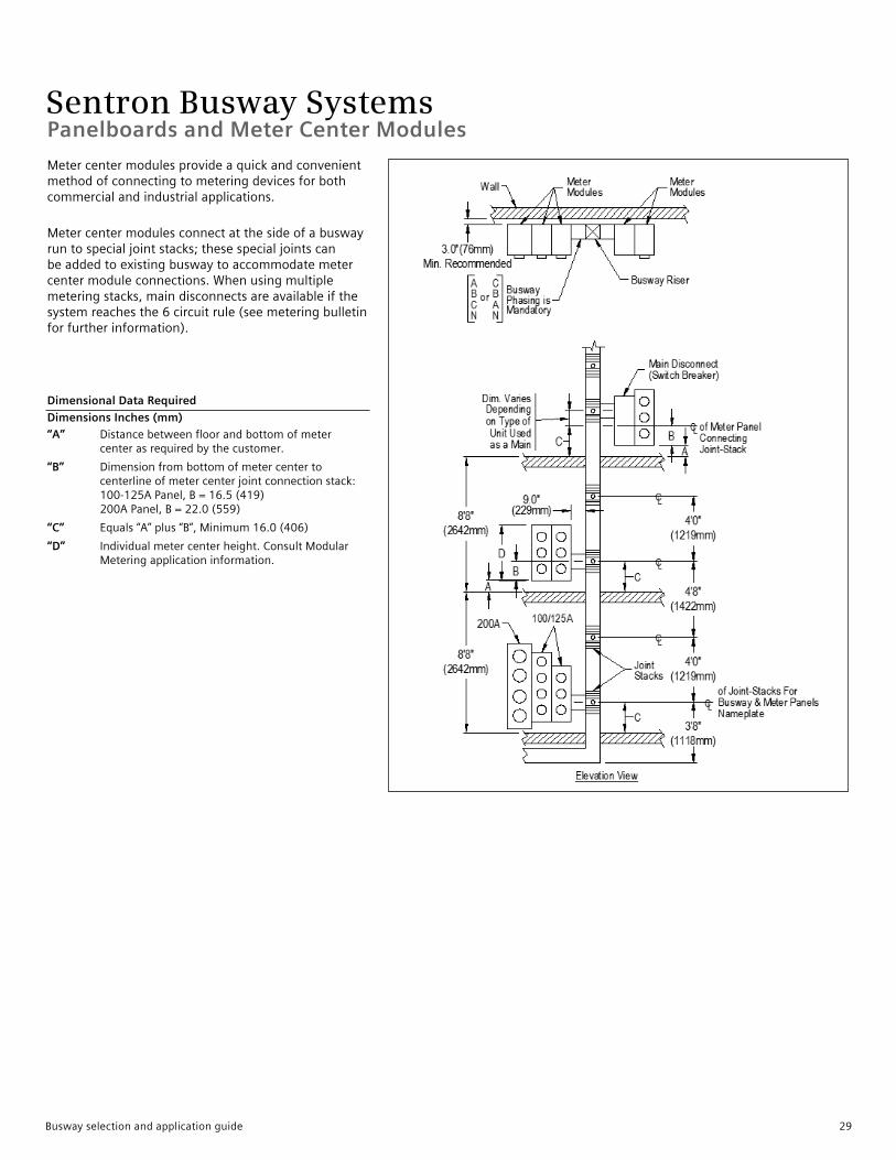
Metercentermodulesprovideaquickandconvenientmethodofconnectingtometeringdevicesforbothcommercialandindustrialapplications.
Metercentermodulesconnectatthesideofabuswayruntospecialjointstacks;thesespecialjointscanbeaddedtoexistingbuswaytoaccommodatemetercentermoduleconnections.Whenusingmultiplemeteringstacks,maindisconnectsareavailableifthesystemreachesthe6circuitrule(seemeteringbulletinforfurtherinformation).
Dimensional Data Required
Dimensions Inches (mm)
“A” Distancebetweenfloorandbottomofmetercenterasrequiredbythecustomer.
“B” Dimensionfrombottomofmetercentertocenterlineofmetercenterjointconnectionstack:100-125APanel,B=16.5(419)200APanel,B=22.0(559)
“C” Equals“A”plus“B”,Minimum16.0(406)
“D” Individualmetercenterheight.ConsultModularMeteringapplicationinformation.
Busway selection and application guide 29
Sentron Busway Systems
Molded Case Circuit Breaker with Meter Tap Stack Provisions Dimensions, Inches (mm)
Ampere RatingBuswayWidth W
L Frame Breaker (250-600A) M Frame Breaker (250-600A) N Frame Breaker (800-1200A)A B C A B C A B C
AL L-Rated225 — 3.9(99) 32(813) 24(620) 16(406) 37(940) 26(660) 16(406) 37(940) 26(660) 16(406)400 — 3.9(99) 32(813) 24(620) 16(406) 37(940) 26(660) 16(406) 37(940) 26(660) 16(406)600 — 3.9(99) 32(813) 24(620) 16(406) 37(940) 26(660) 16(406) 37(940) 26(660) 16(406)800 400 4.6(117) 32(813) 24(610) 16(406) 37(940) 26(660) 16(406) 37(940) 26(660) 16(406)1000 600 5.4(137) 32(813) 24(610) 16(406) 37(940) 26(660) 16(406) 37(940) 26(660) 16(406)1200 800 6.6(168) 32(813) 24(610) 16(406) 37(940) 26(660) 16(406) 37(940) 26(660) 16(406)1350 1000 7.6(193) 32(813) 24(610) 16(406) 37(940) 26(660) 16(406) 37(940) 26(660) 16(406)1600 1200 8.7(221) 32(813) 24(610) 20(490) 37(940) 26(660) 20(490) 37(940) 26(660) 20(490)2000 1350,1600 10.9(277) 32(813) 24(610) 20(490) 37(940) 26(660) 20(490) 37(940) 26(660) 20(490)2500 2000 13.7(348) 32(813) 24(610) 23.5(597) 37(940) 26(660) 23.5(597) 37(940) 26(660) 23.5(597)3000 2500 15.8(401) 32(813) 24(610) 23.5(597) 37(940) 26(660) 23.5(597) 37(940) 26(660) 23.5(597)3200 2000 17.3(439) 32(813) 24(610) 23.5(597) 37(940) 26(660) 28(711) 37(940) 26(660) 28(711)4000 3000,3200 20.3(516) 32(813) 24(610) 28(711) 37(940) 26(660) 28(711) 37(940) 26(660) 28(711)4000 3000,3200 20.3(516) 32(813) 24(610) 28(711) 37(940) 26(660) 28(711) 37(940) 26(660) 28(711)CU M-Rated225 — 3.9(99) 32(813) 24(620) 16(406) 37(940) 26(660) 16(406) 37(940) 26(660) 16(406)400 — 3.9(99) 32(813) 24(620) 16(406) 37(940) 26(660) 16(406) 37(940) 26(660) 16(406)600 — 3.9(99) 32(813) 24(620) 16(406) 37(940) 26(660) 16(406) 37(940) 26(660) 16(406)800 400 3.9(99) 32(813) 24(620) 16(406) 37(940) 26(660) 16(406) 37(940) 26(660) 16(406)1000 — 4.4(112) 32(813) 24(610) 16(406) 37(940) 26(660) 16(406) 37(940) 26(660) 16(406)1200 600 5.1(130) 32(813) 24(610) 16(406) 37(940) 26(660) 16(406) 37(940) 26(660) 16(406)1350 800 5.7(145) 32(813) 24(610) 16(406) 37(940) 26(660) 16(406) 37(940) 26(660) 16(406)1600 1000 6.7(170) 32(813) 24(610) 16(406) 37(940) 26(660) 16(406) 37(940) 26(660) 16(406)2000 1200,1350 8.2(208) 32(813) 24(610) 20(490) 37(940) 26(660) 20(490) 37(940) 26(660) 20(490)— 1600 8.7(221) 32(813) 24(610) 20(490) 37(940) 26(660) 20(490) 37(940) 26(660) 20(490)2500 2000 10.7(272) 32(813) 24(610) 20(490) 37(940) 26(660) 20(490) 37(940) 26(660) 20(490)3000 — 11.8(300) 32(813) 24(610) 20(490) 37(940) 26(660) 20(490) 37(940) 26(660) 20(490)3200 — 13.3(335) 32(813) 24(610) 20(490) 37(940) 26(660) 23.5(597) 37(940) 26(660) 23.5(597)4000 2500,3000,3200 15.3(389) 32(813) 24(610) 23.5(597) 37(940) 26(660) 23.5(597) 37(940) 26(660) 23.5(597)5000 4000 19.3(491) 32(813) 24(610) 28(711) 37(940) 26(660) 28(711) 37(940) 26(660) 28(711)
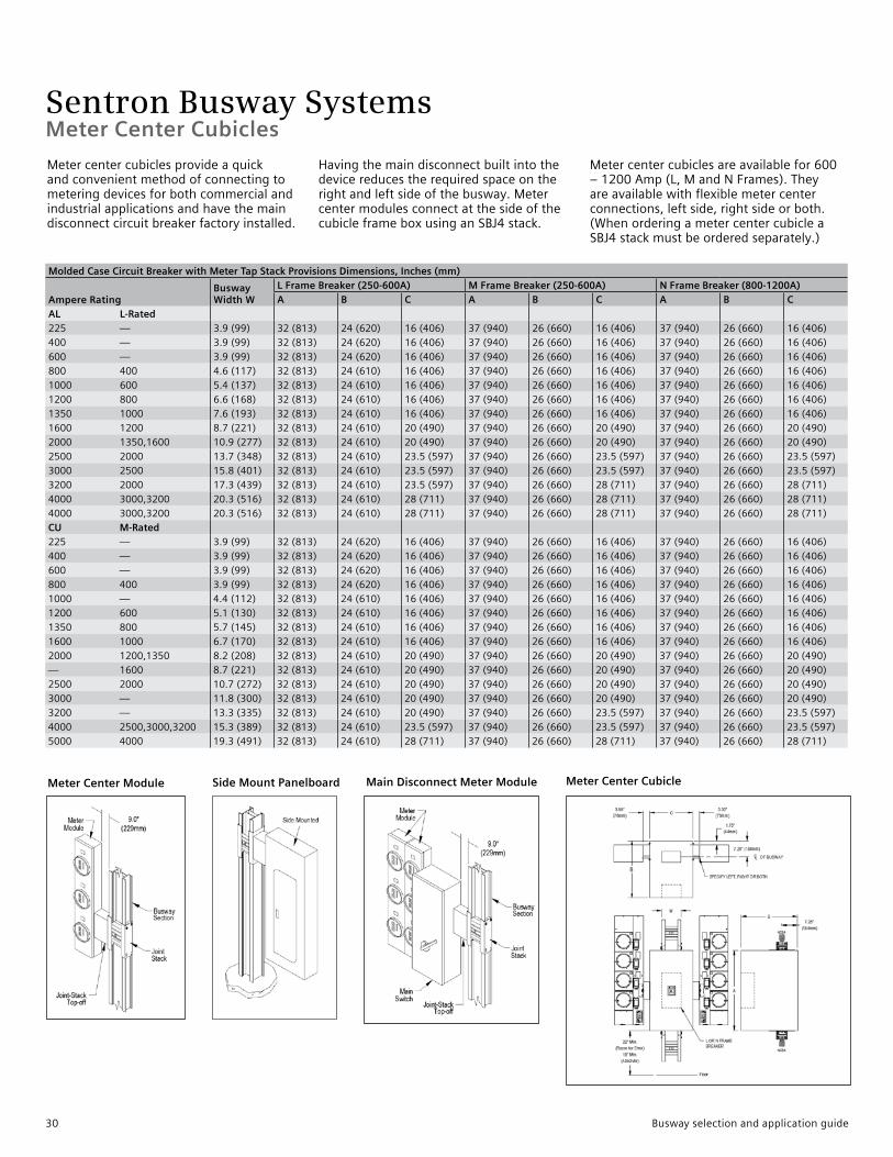
Meter Center Cubicle
Meter Center Cubicles
Meter Center Module Main Disconnect Meter ModuleSide Mount Panelboard
Metercentercubiclesprovideaquickandconvenientmethodofconnectingtometeringdevicesforbothcommercialandindustrialapplicationsandhavethemaindisconnectcircuitbreakerfactoryinstalled.
Havingthemaindisconnectbuiltintothedevicereducestherequiredspaceontherightandleftsideofthebusway.MetercentermodulesconnectatthesideofthecubicleframeboxusinganSBJ4stack.
Metercentercubiclesareavailablefor600–1200Amp(L,MandNFrames).Theyareavailablewithflexiblemetercenterconnections,leftside,rightsideorboth.(WhenorderingametercentercubicleaSBJ4stackmustbeorderedseparately.)
30 Busway selection and application guide
Sentron Busway SystemsInstallation and Application Information
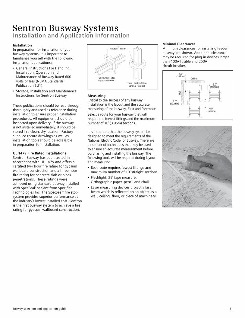
Installation Inpreparationforinstallationofyourbuswaysystems,itisimportanttofamiliarizeyourselfwiththefollowinginstallationpublications:
• GeneralInstructionsForHandling,Installation,OperationandMaintenanceofBuswayRated600voltsorless(NEMAStandardsPublicationBU1)
• Storage,InstallationandMaintenanceInstructionsforSentronBusway
Thesepublicationsshouldbereadthroughthoroughlyandusedasreferenceduringinstallationtoensureproperinstallationprocedures.Allequipmentshouldbeinspectedupondelivery.Ifthebuswayisnotinstalledimmediately,itshouldbestoredinaclean,drylocation.Factorysuppliedrecorddrawingsaswellasinstallationtoolsshouldbeaccessibleinpreparationforinstallation.
UL 1479 Fire Rated Installations SentronBuswayhasbeentestedinaccordancewithUL1479andoffersacertifiedtwohourfireratingforgypsumwallboardconstructionandathreehourfireratingforconcreteslaborblockpenetrations.TheseratingswereachievedusingstandardbuswayinstalledwithSpecSeal®sealantfromSpecifiedTechnologiesInc.TheSpecSeal®firestopsystemprovidessuperiorperformanceattheindustry’slowestinstalledcost.Sentronisthefirstbuswaysystemtoachieveafireratingforgypsumwallboardconstruction.
Measuring Criticaltothesuccessofanybuswayinstallationisthelayoutandtheaccuratemeasuringofthebusway.Firstandforemost:
Selectarouteforyourbuswaythatwillrequirethefewestfittingsandthemaximumnumberof10'(3.05m)sections.ItisimportantthatthebuswaysystembedesignedtomeettherequirementsoftheNationalElectricCodeforBusway.Thereareanumberoftechniquesthatmaybeusedtoensureanaccuratemeasurementbeforepurchasingandinstallingthebusway.Thefollowingtoolswillberequiredduringlayoutandmeasuring:
• Bestrouterequiresfewestfittingsandmaximumnumberof10’straightsections
• Flashlight,25’tapemeasure,Orthographicpaper,pencilandchalk
• Lasermeasuringdevicesprojectalaserbeamwhichisreflectedonanobjectasawall,ceiling,floor,orpieceofmachinery
Minimal Clearances Minimumclearancesforinstallingfeederbuswayareshown.Additionalclearancemayberequiredforplug-indeviceslargerthan100Afusibleand250Acircuitbreaker.
Busway selection and application guide 31
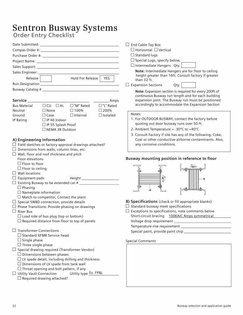
Sentron Busway SystemsOrder Entry Checklist
Ex.FP&L
DateSubmitted:___________________________________________
CompasOrder#:___________________________________________
PurchaseOrder#:__________________________________________
ProjectName: _____________________________________________
SalesSupport:_____________________________________________
SalesEngineer:____________________________________________
Release HoldForReleaseYES
RunDesignation___________________________________________
BuswayCatalog#__________________________________________
Service_________________________________________Amps
BusMaterial CU AL “M”Rated “L”RatedNeutral None 100% 200%Ground Case Internal IsolatedIPRating IP40Indoor IP55SplashProof NEMA3ROutdoor
A) Engineering Information Fieldsketchesorfactoryapprovaldrawingsattached?Dimensionsfromwalls,columnlines,etc.Wall,floorandroofthicknessandpitch
Floorelevations Floortofloor FloortoceilingWalllocationsEquipmentpads Height_____________________ExistingBuswaytobeextendedcat#______________________
Phasing Nameplateinformation Matchtocompetitor,ContacttheplantSpecialSWBDconnection,providedetailsPhaseTransitions:ProvidephasingondrawingsRiserBus
Loadsideofbusplug(toporbottom) Requireddistancefromfloortotopofpanels
TransformerConnections StandardXFMRServicehead Singlephase ThreesinglephaseSpecialdrawingrequired(TransformerVendor)
Dimensionsbetweenphases LVspadedetail,includingdrillingandthickness DimensionsofLVspadefromtankwall Throatopeningandboltpattern,ifanyUtilityVaultConnection Utilitytype_________________
Requireddrawingattached?
EndCableTapBox
Horizontal Vertical
Standardlugs
SpecialLugs,specifybelow,
IntermediateHangersQty.
Note:IntermediateHangersareforfloortoceiling heightgreaterthan16ft.Consultfactoryifgreater than32ft.
ExpansionSections Qty.
Note:Expansionsectionisrequiredforevery200ftof continuousBuswayrunlengthandforeachbuilding expansionjoint.TheBuswayrunmustbepositioned accordinglytoaccommodatetheExpansionSection
Notes: 1.ForOUTDOORBUSWAY,contactthefactorybefore quotingoutdoorbuswayrunsover50ft.
2.AmbientTemperature=-30ºCto+40ºC
3.ConsultFactoryifsitehasanyofthefollowing:Coke, Coalorotherconductiveairbornecontaminants.Also, anycorrosiveconditions.
Busway mounting position in reference to floor
B) Specifications (checkorfillappropriateblanks)StandardbuswaymeetspecificationsExceptionstospecifications,notecommentsbelow
Short-circuitbracing 100KAICAmpssymmetrical
Voltagedroprequirement________________________________
Temperature-riserequirement____________________________
Specialpaint,providepaintchip___________________________
SpecialComments
32 Busway selection and application guide
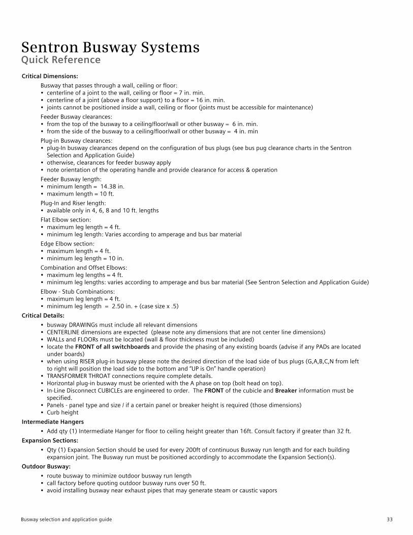
Sentron Busway SystemsQuick Reference
Critical Dimensions:
Buswaythatpassesthroughawall,ceilingorfloor: • centerlineofajointtothewall,ceilingorfloor=7in.min. • centerlineofajoint(aboveafloorsupport)toafloor=16in.min. • jointscannotbepositionedinsideawall,ceilingorfloor(jointsmustbeaccessibleformaintenance)
FeederBuswayclearances: • fromthetopofthebuswaytoaceiling/floor/wallorotherbusway=6in.min. • fromthesideofthebuswaytoaceiling/floor/wallorotherbusway=4in.min
Plug-inBuswayclearances: • plug-Inbuswayclearancesdependontheconfigurationofbusplugs(seebuspugclearancechartsintheSentron SelectionandApplicationGuide) • otherwise,clearancesforfeederbuswayapply • noteorientationoftheoperatinghandleandprovideclearanceforaccess&operation
FeederBuswaylength: • minimumlength=14.38in. • maximumlength=10ft.
Plug-InandRiserlength: • availableonlyin4,6,8and10ft.lengths
FlatElbowsection: • maximumleglength=4ft. • minimumleglength:Variesaccordingtoamperageandbusbarmaterial
EdgeElbowsection: • maximumlength=4ft. • minimumleglength=10in.
CombinationandOffsetElbows: • maximumleglengths=4ft. • minimumleglengths:variesaccordingtoamperageandbusbarmaterial(SeeSentronSelectionandApplicationGuide)
Elbow-StubCombinations: • maximumleglength=4ft. • minimumleglength=2.50in.+(casesizex.5)
Critical Details:
• buswayDRAWINGsmustincludeallrelevantdimensions • CENTERLINEdimensionsareexpected(pleasenoteanydimensionsthatarenotcenterlinedimensions) • WALLsandFLOORsmustbelocated(wall&floorthicknessmustbeincluded) • locatetheFRONT of all switchboardsandprovidethephasingofanyexistingboards(adviseifanyPADsarelocated underboards) • whenusingRISERplug-inbuswaypleasenotethedesireddirectionoftheloadsideofbusplugs(G,A,B,C,Nfromleft torightwillpositiontheloadsidetothebottomand“UPisOn”handleoperation) • TRANSFORMERTHROATconnectionsrequirecompletedetails. • Horizontalplug-inbuswaymustbeorientedwiththeAphaseontop(boltheadontop). • In-LineDisconnectCUBICLEsareengineeredtoorder.TheFRONTofthecubicleandBreakerinformationmustbe specified. • Panels-paneltypeandsize/ifacertainpanelorbreakerheightisrequired(thosedimensions) • Curbheight
Intermediate Hangers
• Addqty(1)IntermediateHangerforfloortoceilingheightgreaterthan16ft.Consultfactoryifgreaterthan32ft.
Expansion Sections:
• Qty(1)ExpansionSectionshouldbeusedforevery200ftofcontinuousBuswayrunlengthandforeachbuilding expansionjoint.TheBuswayrunmustbepositionedaccordinglytoaccommodatetheExpansionSection(s).
Outdoor Busway:
• routebuswaytominimizeoutdoorbuswayrunlength • callfactorybeforequotingoutdoorbuswayrunsover50ft. • avoidinstallingbuswaynearexhaustpipesthatmaygeneratesteamorcausticvapors
Busway selection and application guide 33
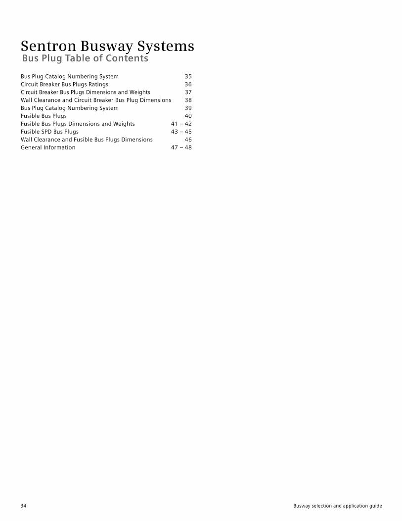
Sentron Busway Systems
BusPlugCatalogNumberingSystem 35CircuitBreakerBusPlugsRatings 36 CircuitBreakerBusPlugsDimensionsandWeights 37WallClearanceandCircuitBreakerBusPlugDimensions 38BusPlugCatalogNumberingSystem 39FusibleBusPlugs 40FusibleBusPlugsDimensionsandWeights 41–42FusibleSPDBusPlugs 43–45WallClearanceandFusibleBusPlugsDimensions 46GeneralInformation 47–48
Bus Plug Table of Contents
34 Busway selection and application guide
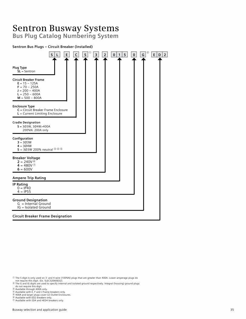
Sentron Busway Systems
1TheSdigitisonlyusedon3-and4-wire(100%N)plugsthataregreaterthan400A.Loweramperageplugsdo notrequirethisdigit.(Ex.SLEC32060ED2).2 TheGandIGdigitsareusedtospecifyinternalandisolatedgroundrespectively.Integral(housing)groundplugs donotrequirethisdigit.3 Availablethrough400Aonly.4 AvailablewithE,FandJFramebreakersonly.5 400Aandlargerplugscover(2)OutletEnclosures.6 AvailablewithED2breakersonly.7 AvailablewithED4andHED4breakersonly.
Bus Plug Catalog Numbering System
S L 0 1 E DE C S 3 2 0 G5 221
Sentron Bus Plugs – Circuit Breaker (Installed)
Plug Type SL=Sentron
Circuit Breaker Frame E=15–125A F =70–250A J =200–400A L =250–600A M =500–800A
Enclosure Type C =CircuitBreakerFrameEnclosure L =CurrentLimitingEnclosure
Cradle Designation S = 3Ø3W,3Ø4W>400A 200%N.200Aonly
Configuration 3 = 3Ø3W 4 =3Ø4W 5 =3Ø3W200%neutral3 4 5
Breaker Voltage 2=240V6 4=480V7
Ampere Trip Rating
IP Rating 0=IP40 4=IP55
Ground Designation G=InternalGround IG=IsolatedGround
Circuit Breaker Frame Designation
6=600V
Busway selection and application guide 35
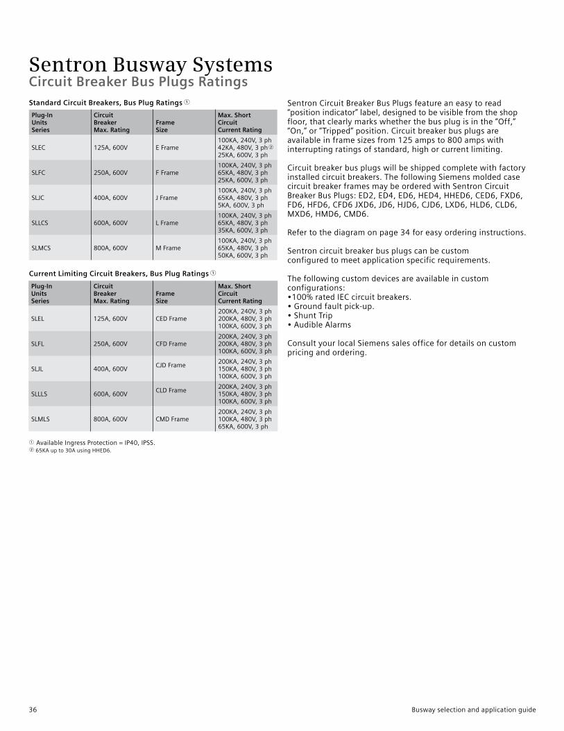
Sentron Busway Systems
SentronCircuitBreakerBusPlugsfeatureaneasytoread“positionindicator”label,designedtobevisiblefromtheshopfloor,thatclearlymarkswhetherthebusplugisinthe“Off,”“On,”or“Tripped”position.Circuitbreakerbusplugsareavailableinframesizesfrom125ampsto800ampswithinterruptingratingsofstandard,highorcurrentlimiting.
Circuitbreakerbusplugswillbeshippedcompletewithfactoryinstalledcircuitbreakers.ThefollowingSiemensmoldedcasecircuitbreakerframesmaybeorderedwithSentronCircuitBreakerBusPlugs:ED2,ED4,ED6,HED4,HHED6,CED6,FXD6,FD6,HFD6,CFD6JXD6,JD6,HJD6,CJD6,LXD6,HLD6,CLD6,MXD6,HMD6,CMD6.
Refertothediagramonpage34foreasyorderinginstructions.
Sentroncircuitbreakerbusplugscanbecustomconfiguredtomeetapplicationspecificrequirements.
Thefollowingcustomdevicesareavailableincustomconfigurations:•100%ratedIECcircuitbreakers.•Groundfaultpick-up.•ShuntTrip•AudibleAlarms
ConsultyourlocalSiemenssalesofficefordetailsoncustompricingandordering.
Plug-In Units Series
Circuit Breaker Max. Rating
Frame Size
Max. Short Circuit Current Rating
SLEC 125A,600V EFrame100KA,240V,3ph42KA,480V,3ph2
25KA,600V,3ph
SLFC 250A,600V FFrame100KA,240V,3ph65KA,480V,3ph25KA,600V,3ph
SLJC 400A,600V JFrame100KA,240V,3ph65KA,480V,3ph5KA,600V,3ph
SLLCS 600A,600V LFrame100KA,240V,3ph65KA,480V,3ph35KA,600V,3ph
SLMCS 800A,600V MFrame100KA,240V,3ph65KA,480V,3ph50KA,600V,3ph
Plug-In Units Series
Circuit Breaker Max. Rating
Frame Size
Max. Short Circuit Current Rating
SLEL 125A,600V CEDFrame200KA,240V,3ph200KA,480V,3ph100KA,600V,3ph
SLFL 250A,600V CFDFrame200KA,240V,3ph200KA,480V,3ph100KA,600V,3ph
SLJL 400A,600VCJDFrame
200KA,240V,3ph150KA,480V,3ph100KA,600V,3ph
SLLLS 600A,600VCLDFrame
200KA,240V,3ph150KA,480V,3ph100KA,600V,3ph
SLMLS 800A,600V CMDFrame200KA,240V,3ph100KA,480V,3ph65KA,600V,3ph
Standard Circuit Breakers, Bus Plug Ratings 1
Current Limiting Circuit Breakers, Bus Plug Ratings 1
1 AvailableIngressProtection=IP40,IPSS.265KAupto30AusingHHED6.
Circuit Breaker Bus Plugs Ratings
36 Busway selection and application guide

Sentron Busway SystemsCircuit Breaker Bus Plugs Dimensions and Weights
Ampere Rating
Dimensions Inches (mm) Weightlbs (kg)“A” “B” “C” “D” max. “E” “F” “J” “K”
125 15.13(384) 10.18(259) 9.75(248) 1.60(41) 2.50(64) 2.50(64) 3.50(89) 2.25(57) 35(15.87)250 20.25(514) 10.18(259) 9.75(248) 1.60(41) 2.50(64) 2.50(64) 3.25(83) 3.25(83) 50(22.68)400 21.75(552) 16.75(425) 11.75(298) 1.60(41) 5.75(146) 5.75(146) 4.00(102) 3.25(83) 83(37.64)600 41.50(1054) 19.75(502) 15.75(400) 2.31(59) 7.00(178) 7.75(197) — — 130(58.97)800 41.50(1054) 19.75(502) 15.75(400) 2.31(59) 7.00(178) 7.75(197) — — 177(80.29)
Circuit Breaker Bus Plugs, Load Lugs and Knockouts
Frame Size
Ground Lug Cu/Al
Neutral Lug Cu/AI
Phase LugCu/AI
Knockout Sizes In. (mm)
EFrame #14-2 #14-2 #14-1/0 7/8(22)FFrame #14-2 #6-350kcmil #6-350kcmil 7/8(22)JFrame #14-2 (2)#4-500kcmil (2)3/0-500kcmil 7/8(22)
125 – 400A Bus Plugs
600 – 800A Bus Plugs
Circuit Breaker Bus Plugs, Dimensions and Weights (Enclosure only)
Busway selection and application guide 37
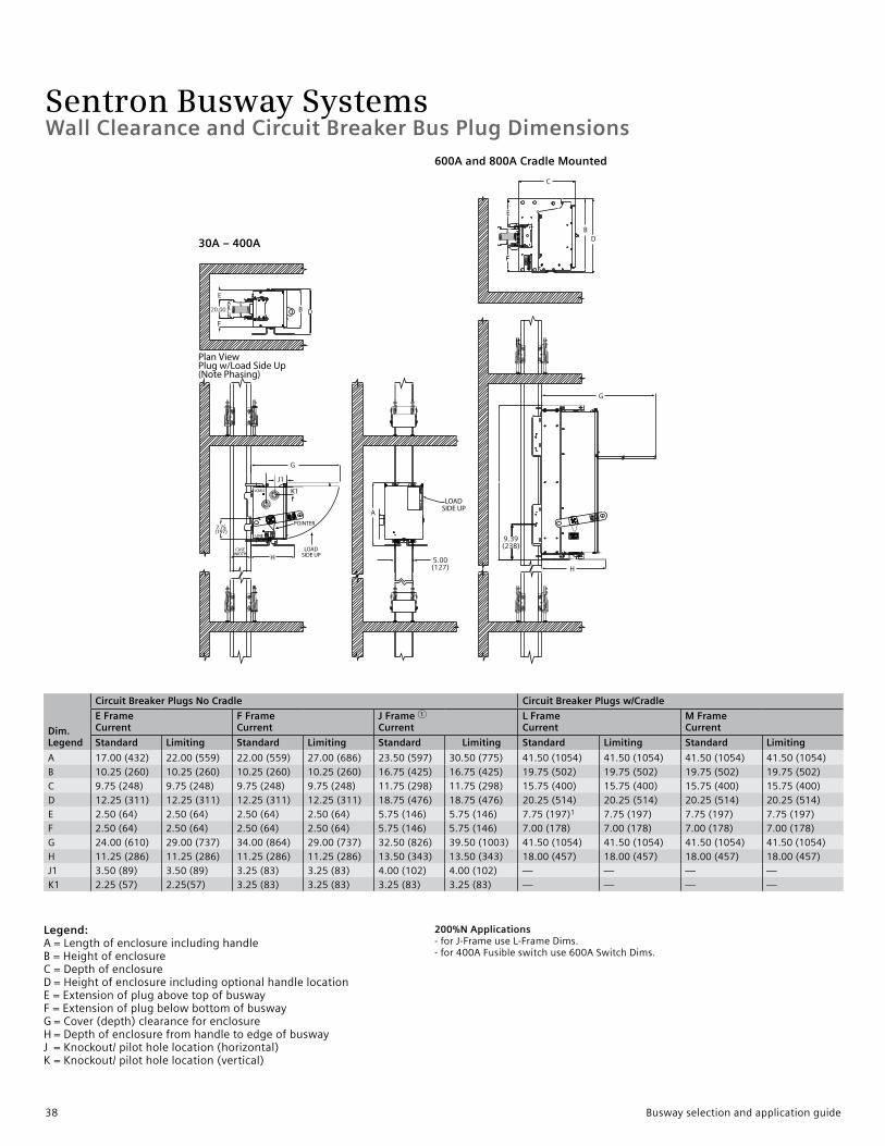
Sentron Busway Systems
30A – 400A
600A and 800A Cradle Mounted
Legend: A=Lengthofenclosureincludinghandle B=Heightofenclosure C=Depthofenclosure D=HeightofenclosureincludingoptionalhandlelocationE=ExtensionofplugabovetopofbuswayF=ExtensionofplugbelowbottomofbuswayG=Cover(depth)clearanceforenclosureH=DepthofenclosurefromhandletoedgeofbuswayJ=Knockout/pilotholelocation(horizontal)K=Knockout/pilotholelocation(vertical)
200%N Applications -forJ-FrameuseL-FrameDims.-for400AFusibleswitchuse600ASwitchDims.
Dim. Legend
Circuit Breaker Plugs No Cradle Circuit Breaker Plugs w/Cradle
E Frame Current
F Frame Current
J Frame 1Current
L FrameCurrent
M FrameCurrent
Standard Limiting Standard Limiting Standard Limiting Standard Limiting Standard Limiting
A 17.00(432) 22.00(559) 22.00(559) 27.00(686) 23.50(597) 30.50(775) 41.50(1054) 41.50(1054) 41.50(1054) 41.50(1054)B 10.25(260) 10.25(260) 10.25(260) 10.25(260) 16.75(425) 16.75(425) 19.75(502) 19.75(502) 19.75(502) 19.75(502)C 9.75(248) 9.75(248) 9.75(248) 9.75(248) 11.75(298) 11.75(298) 15.75(400) 15.75(400) 15.75(400) 15.75(400)D 12.25(311) 12.25(311) 12.25(311) 12.25(311) 18.75(476) 18.75(476) 20.25(514) 20.25(514) 20.25(514) 20.25(514)E 2.50(64) 2.50(64) 2.50(64) 2.50(64) 5.75(146) 5.75(146) 7.75(197)1 7.75(197) 7.75(197) 7.75(197)F 2.50(64) 2.50(64) 2.50(64) 2.50(64) 5.75(146) 5.75(146) 7.00(178) 7.00(178) 7.00(178) 7.00(178)G 24.00(610) 29.00(737) 34.00(864) 29.00(737) 32.50(826) 39.50(1003) 41.50(1054) 41.50(1054) 41.50(1054) 41.50(1054)H 11.25(286) 11.25(286) 11.25(286) 11.25(286) 13.50(343) 13.50(343) 18.00(457) 18.00(457) 18.00(457) 18.00(457)J1 3.50(89) 3.50(89) 3.25(83) 3.25(83) 4.00(102) 4.00(102) — — — —K1 2.25(57) 2.25(57) 3.25(83) 3.25(83) 3.25(83) 3.25(83) — — — —
Wall Clearance and Circuit Breaker Bus Plug Dimensions
38 Busway selection and application guide
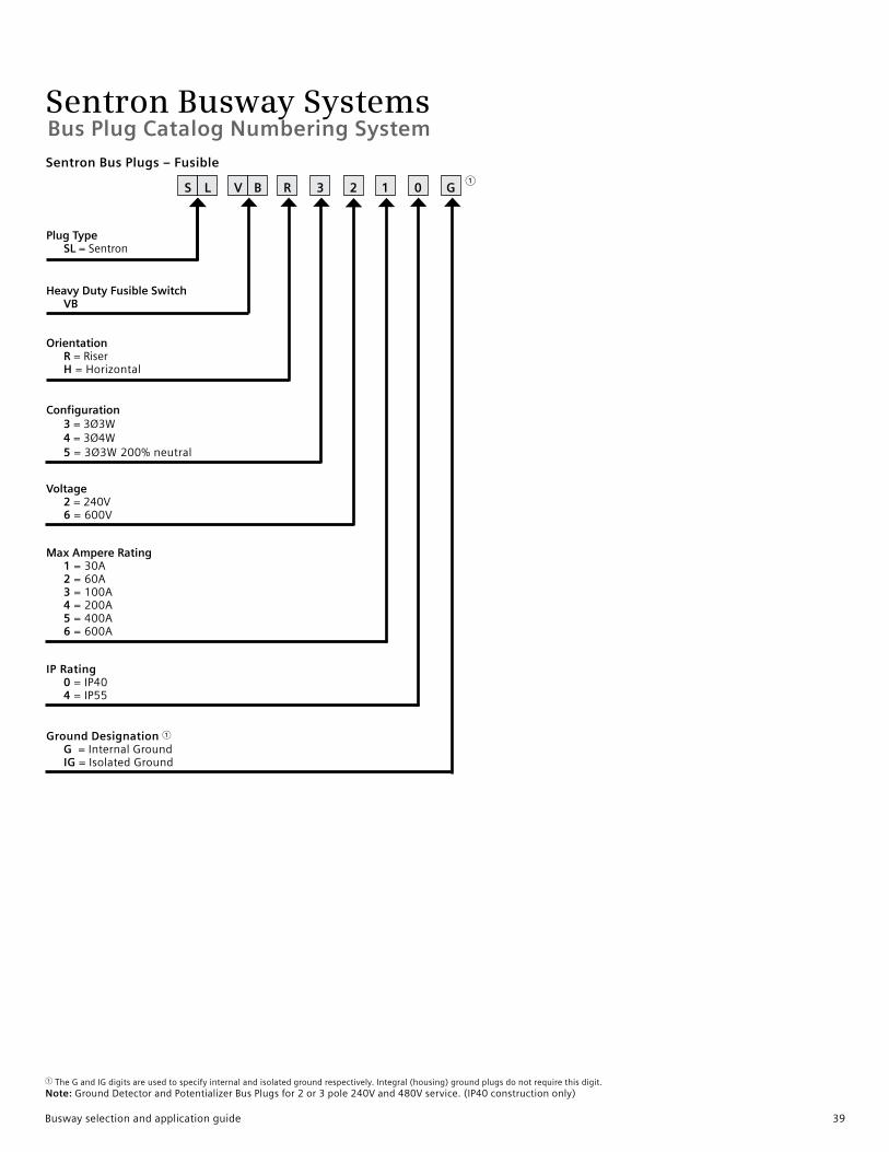
Sentron Busway Systems
Plug Type SL=Sentron
Heavy Duty Fusible Switch VB
Orientation R =Riser H =Horizontal
Configuration 3 =3Ø3W 4 =3Ø4W 5 =3Ø3W200%neutral
Voltage 2 =240V 6 =600V
Max Ampere Rating 1 =30A 2 =60A 3 =100A 4 =200A 5 =400A 6 =600A
IP Rating 0 =IP40 4 =IP55
Ground Designation 1 G =InternalGround IG =IsolatedGround
S L V B R 3 2 1 0 G1
Sentron Bus Plugs – Fusible
Bus Plug Catalog Numbering System
1 TheGandIGdigitsareusedtospecifyinternalandisolatedgroundrespectively.Integral(housing)groundplugsdonotrequirethisdigit.Note:GroundDetectorandPotentializerBusPlugsfor2or3pole240Vand480Vservice.(IP40constructiononly)
Busway selection and application guide 39
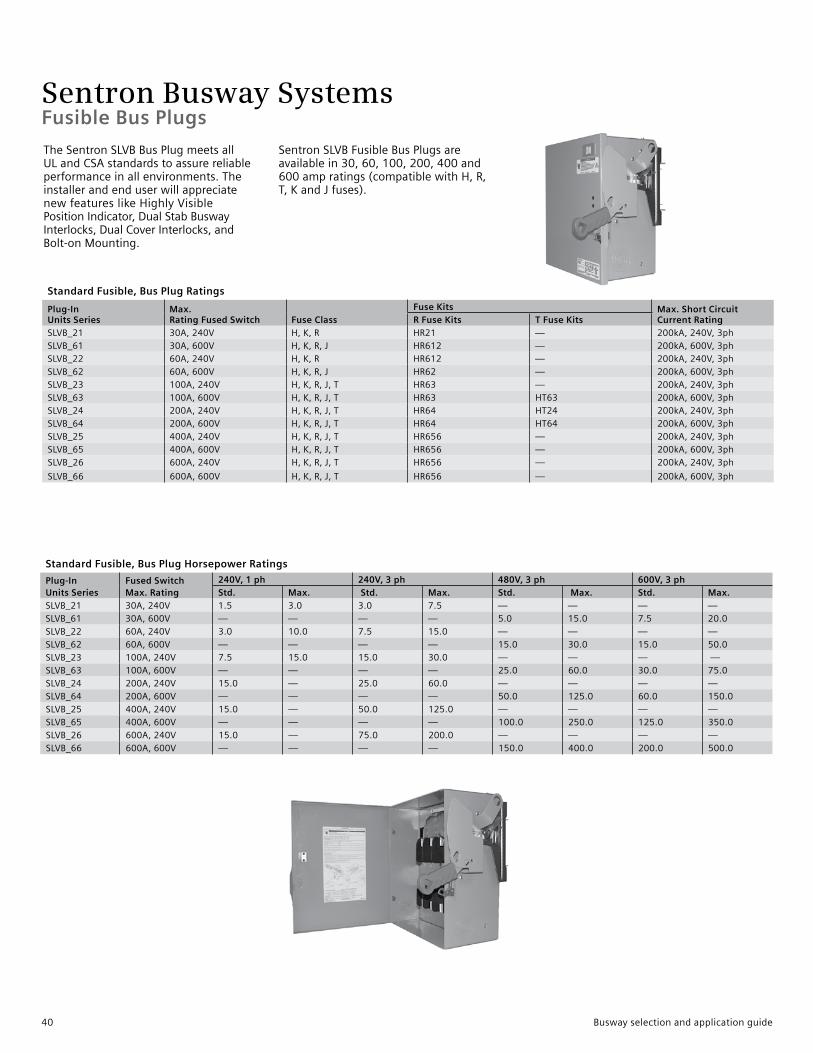
Sentron Busway Systems
TheSentronSLVBBusPlugmeetsallULandCSAstandardstoassurereliableperformanceinallenvironments.TheinstallerandenduserwillappreciatenewfeatureslikeHighlyVisiblePositionIndicator,DualStabBuswayInterlocks,DualCoverInterlocks,andBolt-onMounting.
SentronSLVBFusibleBusPlugsareavailablein30,60,100,200,400and600ampratings(compatiblewithH,R,T,KandJfuses).
Standard Fusible, Bus Plug Ratings
Plug-In Units Series
Max. Rating Fused Switch Fuse Class
Fuse Kits Max. Short CircuitCurrent RatingR Fuse Kits T Fuse Kits
SLVB_21 30A,240V H,K,R HR21 — 200kA,240V,3phSLVB_61 30A,600V H,K,R,J HR612 — 200kA,600V,3phSLVB_22 60A,240V H,K,R HR612 — 200kA,240V,3phSLVB_62 60A,600V H,K,R,J HR62 — 200kA,600V,3phSLVB_23 100A,240V H,K,R,J,T HR63 — 200kA,240V,3phSLVB_63 100A,600V H,K,R,J,T HR63 HT63 200kA,600V,3phSLVB_24 200A,240V H,K,R,J,T HR64 HT24 200kA,240V,3phSLVB_64 200A,600V H,K,R,J,T HR64 HT64 200kA,600V,3phSLVB_25 400A,240V H,K,R,J,T HR656 — 200kA,240V,3phSLVB_65 400A,600V H,K,R,J,T HR656 — 200kA,600V,3phSLVB_26 600A,240V H,K,R,J,T HR656 — 200kA,240V,3ph
SLVB_66 600A,600V H,K,R,J,T HR656 — 200kA,600V,3ph
Standard Fusible, Bus Plug Horsepower Ratings
Plug-In Units Series
Fused Switch Max. Rating
240V, 1 ph 240V, 3 ph 480V, 3 ph 600V, 3 phStd. Max. Std. Max. Std. Max. Std. Max.
SLVB_21 30A,240V 1.5 3.0 3.0 7.5 — — — —SLVB_61 30A,600V — — — — 5.0 15.0 7.5 20.0SLVB_22 60A,240V 3.0 10.0 7.5 15.0 — — — —SLVB_62 60A,600V — — — — 15.0 30.0 15.0 50.0SLVB_23 100A,240V 7.5 15.0 15.0 30.0 — — — —SLVB_63 100A,600V — — — — 25.0 60.0 30.0 75.0SLVB_24 200A,240V 15.0 — 25.0 60.0 — — — —SLVB_64 200A,600V — — — — 50.0 125.0 60.0 150.0SLVB_25 400A,240V 15.0 — 50.0 125.0 — — — —SLVB_65 400A,600V — — — — 100.0 250.0 125.0 350.0SLVB_26 600A,240V 15.0 — 75.0 200.0 — — — —SLVB_66 600A,600V — — — — 150.0 400.0 200.0 500.0
Fusible Bus Plugs
40 Busway selection and application guide
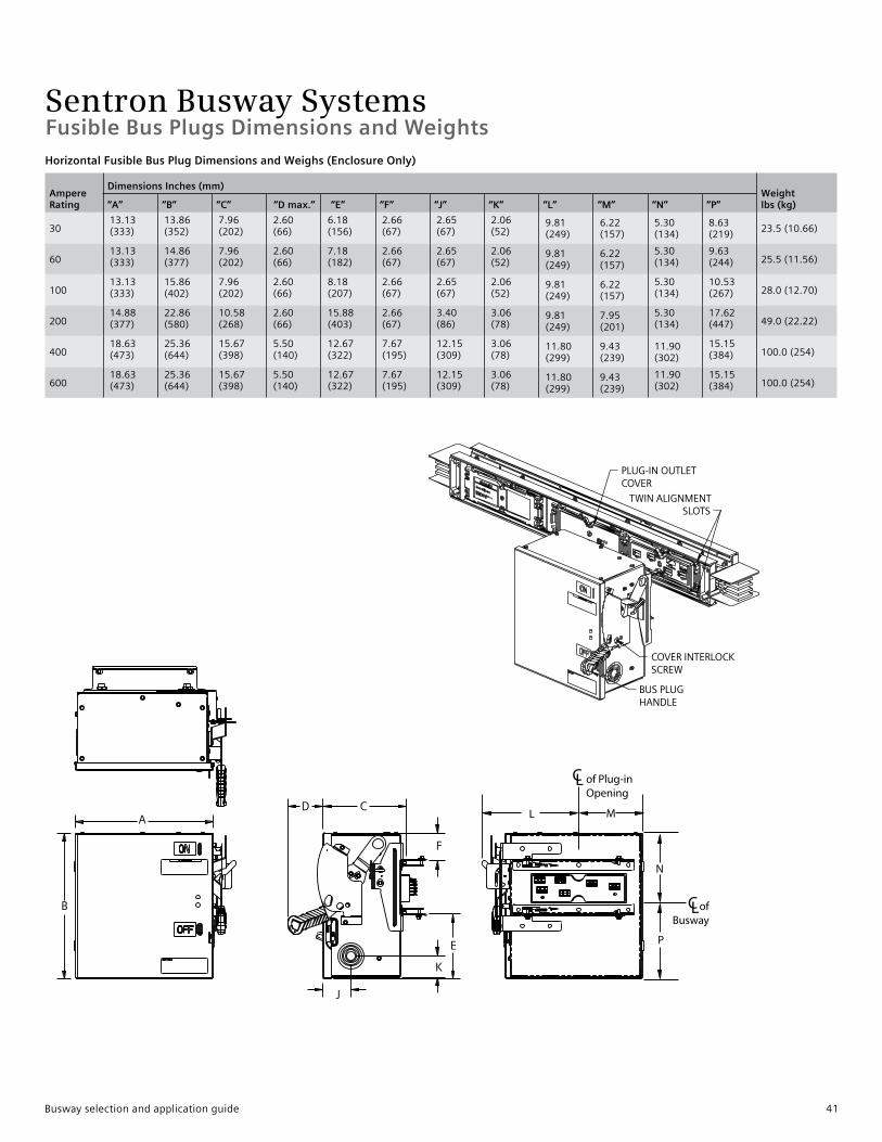
Sentron Busway SystemsFusible Bus Plugs Dimensions and WeightsHorizontal Fusible Bus Plug Dimensions and Weighs (Enclosure Only)
Ampere Rating
Dimensions Inches (mm)Weightlbs (kg)“A” “B” “C” “D max.” “E” “F” “J” “K” “L” “M” “N” “P”
3013.13(333)
13.86(352)
7.96(202)
2.60(66)
6.18(156)
2.66(67)
2.65(67)
2.06(52)
9.81(249)
6.22(157)
5.30(134)
8.63(219)
23.5(10.66)
6013.13(333)
14.86(377)
7.96(202)
2.60(66)
7.18(182)
2.66(67)
2.65(67)
2.06(52)
9.81(249)
6.22(157)
5.30(134)
9.63(244) 25.5(11.56)
10013.13(333)
15.86(402)
7.96(202)
2.60(66)
8.18(207)
2.66(67)
2.65(67)
2.06(52)
9.81(249)
6.22(157)
5.30(134)
10.53(267) 28.0(12.70)
20014.88(377)
22.86(580)
10.58(268)
2.60(66)
15.88(403)
2.66(67)
3.40(86)
3.06(78)
9.81(249)
7.95(201)
5.30(134)
17.62(447) 49.0(22.22)
40018.63(473)
25.36(644)
15.67(398)
5.50(140)
12.67(322)
7.67(195)
12.15(309)
3.06(78)
11.80(299)
9.43(239)
11.90(302)
15.15(384) 100.0(254)
60018.63(473)
25.36(644)
15.67(398)
5.50(140)
12.67(322)
7.67(195)
12.15(309)
3.06(78)
11.80(299)
9.43(239)
11.90(302)
15.15(384) 100.0(254)
Busway selection and application guide 41

Sentron Busway Systems
Riser Fusible Bus Plug Dimensions and Weighs (Enclosure Only)
Ampere Rating
Dimensions Inches (mm) Weightlbs (kg)“A” “B” “C” “D max.” “E” “F” “J” “K” “L” “M” “N” “P”
3010.13(257)
13.86(352)
7.96(202)
5.25(133)
2.74(69)
2.36(59)
2.65(67)
2.06(52)
8.06(204)
5.08(129)
7.83(198)
6.09(154)
23.5(10.66)
6010.13(257)
14.86(377)
7.96(202)
5.25(133)
2.74(69)
2.36(59)
2.65(67)
2.06(52)
8.06(204)
2.08(52)
7.83(198)
7.09(180)
25.5(11.56)
10011.13(282)
15.86(402)
7.96(202)
5.25(133)
3.48(196)
3.36(85)
2.65(67)
2.06(52)
8.06(204)
6.08(154)
7.83(198)
8.09(205)
28.0(12.70)
20014.88(377)
22.86(580)
10.58(268)
5.90(149)
5.11(129)
4.74(120)
3.40(86)
3.06(78)
10.42(264)
7.35(186)
9.08(230)
13.84(351)
49.0(22.22)
40018.63(473)
25.36(644)
15.67(398)
5.50(140)
6.60(167)
7.10(180)
12.15(309)
3.06(78)
11.97(304)
9.25(234)
13.56(344)
13.49(342)
100.0(2540)
60018.63(473)
25.36(644)
15.67(398)
5.50(140)
6.60(167)
7.10(180)
12.15(309)
3.06(78)
11.97(304)
9.25(234)
13.56(344)
13.49(342)
100.0(2540)
Fusible Switch Plug, Load Lugs, and Knockouts
Ampere Rating
Ground Lug Cu/Al
Neutral LugCu/Al
Phase Lug Cu/Al Knockout Sizes Inches (mm)
30 #14-1/0 #14-2 #14-2 7/8(22)60 #14-1/0 #14-1/0 #14-2 7/8(22)100 #14-1/0 #14-1/0 #14-1/0 7/8(22)200 #14-1/0 #6-300MCM #6-300MCM 7/8(22)
400 #6-350MCM(2)1/0-250MCMor(1)1/0-750MCM
(2)1/0-250MCMor(1)1/0-750MCM
7/8(22)
600 #6-350MCM(4)1/0-250MCMor(2)1/0-750MCM
(4)1/0-250MCMor(2)1/0-750MCM
7/8(22)
Fusible Bus Plugs Dimensions and Weights
42 Busway selection and application guide
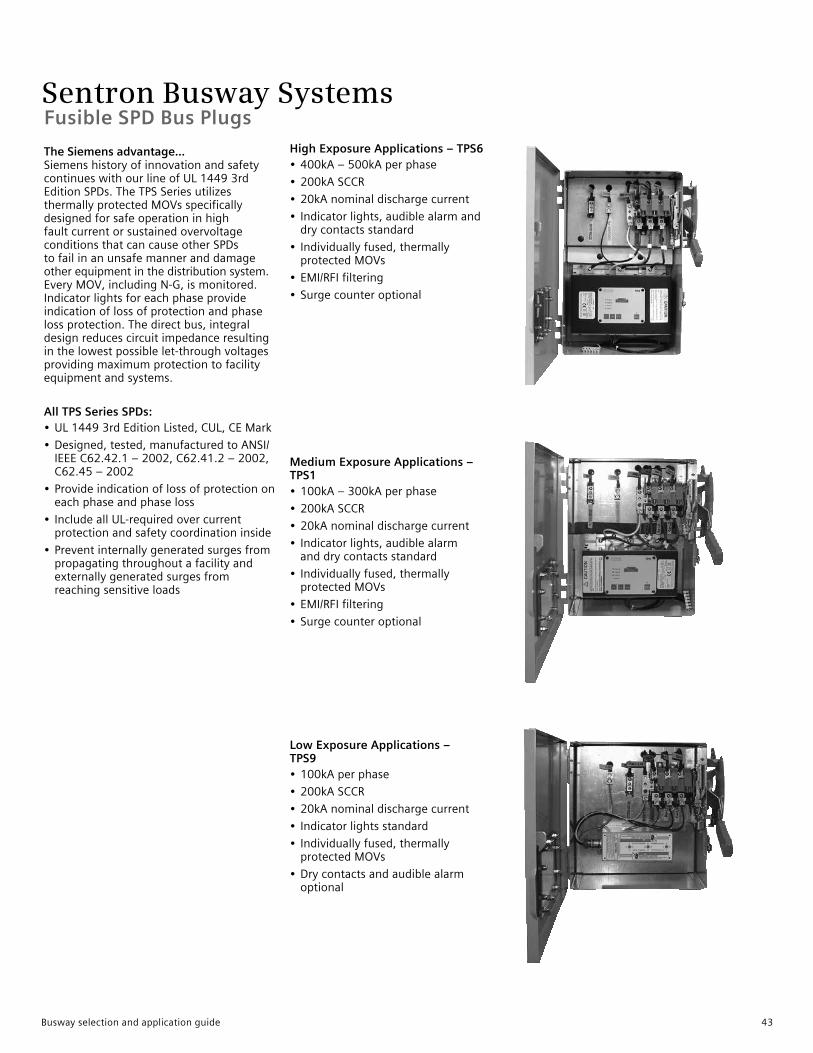
Sentron Busway SystemsFusible SPD Bus Plugs
High Exposure Applications – TPS6 • 400kA–500kAperphase
• 200kASCCR
• 20kAnominaldischargecurrent
• Indicatorlights,audiblealarmanddrycontactsstandard
• Individuallyfused,thermallyprotectedMOVs
• EMI/RFIfiltering
• Surgecounteroptional
Medium Exposure Applications –TPS1 • 100kA–300kAperphase
• 200kASCCR
• 20kAnominaldischargecurrent
• Indicatorlights,audiblealarmanddrycontactsstandard
• Individuallyfused,thermallyprotectedMOVs
• EMI/RFIfiltering
• Surgecounteroptional
Low Exposure Applications – TPS9 • 100kAperphase
• 200kASCCR
• 20kAnominaldischargecurrent
• Indicatorlightsstandard
• Individuallyfused,thermallyprotectedMOVs
• Drycontactsandaudiblealarmoptional
The Siemens advantage...SiemenshistoryofinnovationandsafetycontinueswithourlineofUL14493rdEditionSPDs.TheTPSSeriesutilizesthermallyprotectedMOVsspecificallydesignedforsafeoperationinhighfaultcurrentorsustainedovervoltageconditionsthatcancauseotherSPDstofailinanunsafemanneranddamageotherequipmentinthedistributionsystem.EveryMOV,includingN-G,ismonitored.Indicatorlightsforeachphaseprovideindicationoflossofprotectionandphaselossprotection.Thedirectbus,integraldesignreducescircuitimpedanceresultinginthelowestpossiblelet-throughvoltagesprovidingmaximumprotectiontofacilityequipmentandsystems.
All TPS Series SPDs:• UL14493rdEditionListed,CUL,CEMark
• Designed,tested,manufacturedtoANSI/IEEEC62.42.1–2002,C62.41.2–2002,C62.45–2002
• Provideindicationoflossofprotectiononeachphaseandphaseloss
• IncludeallUL-requiredovercurrentprotectionandsafetycoordinationinside
• Preventinternallygeneratedsurgesfrompropagatingthroughoutafacilityandexternallygeneratedsurgesfromreachingsensitiveloads
Busway selection and application guide 43
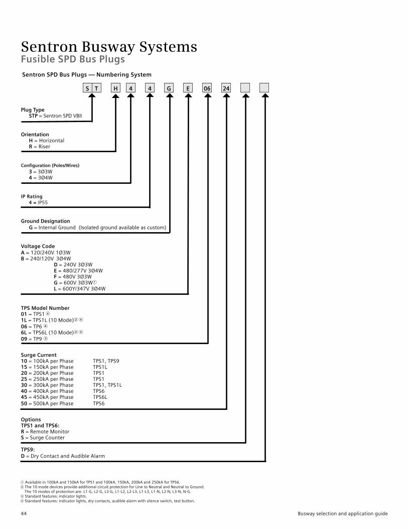
Sentron Busway SystemsFusible SPD Bus Plugs
S T 06H 4 4 G E 24
Sentron SPD Bus Plugs — Numbering System
1Availablein100kAand150kAforTPS1and100kA,150kA,200kAand250kAforTPS6.2 The10modedevicesprovideadditionalcircuitprotectionforLinetoNeutralandNeutraltoGround.The10modesofprotectionare:L1-G,L2-G,L3-G,L1-L2,L2-L3,L1-L3,L1-N,L2-N,L3-N,N-G.3Standardfeatures:indicatorlights.4Standardfeatures:indicatorlights,drycontacts,audiblealarmwithsilenceswitch,testbutton.
Plug Type STP=SentronSPDVBII
Orientation H =Horizontal R =Riser
Configuration (Poles/Wires) 3 = 3Ø3W 4 =3Ø4W
IP Rating 4 = IP55
Ground Designation G = InternalGround(Isolatedgroundavailableascustom)
Voltage Code A=120/240V1Ø3WB=240/120V3Ø4W
D=240V3Ø3WE=480/277V3Ø4WF=480V3Ø3WG=600V3Ø3W1L=600Y/347V3Ø4W
TPS Model Number 01=TPS14
1L=TPS1L(10Mode)2 4
06=TP646L=TPS6L(10Mode)2 4
09=TP93
Surge Current10=100kAperPhase TPS1,TPS915=150kAperPhase TPS1L20=200kAperPhase TPS125=250kAperPhase TPS130=300kAperPhase TPS1,TPS1L40=400kAperPhase TPS645=450kAperPhase TPS6L50=500kAperPhase TPS6
OptionsTPS1 and TPS6:R=RemoteMonitorS=SurgeCounter
TPS9:D=DryContactandAudibleAlarm
44 Busway selection and application guide
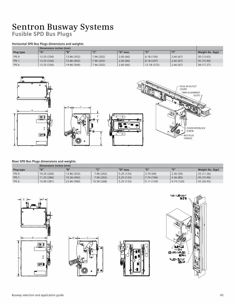
Sentron Busway SystemsFusible SPD Bus Plugs
Horizontal SPD Bus Plugs dimensions and weights
Plug type
Dimensions inches (mm)
“A” “B” “C” “D” max. “E” “F” Weight lbs. (kgs)
TPS9 13.25(336) 13.86(352) 7.96(202) 2.60(66) 6.18(156) 2.66(67) 30(13.63)
TPS1 13.25(336) 15.86(402) 7.96(202) 2.60(66) 8.18(207) 2.66(67) 35(15.90)
TPS6 13.25(336) 19.86(504) 7.96(202) 2.60(66) 12.18(372) 2.66(67) 38(17.27)
Riser SPD Bus Plugs dimensions and weights
Plug type
Dimensions inches (mm)
“A” “B” “C” “D” max. “E” “F” Weight lbs. (kgs)
TPS9 10.25(260) 13.86(352) 7.96(202) 5.25(133) 2.74(69) 2.36(59) 25(11.36)TPS1 11.25(286) 19.36(492) 7.96(202) 5.25(133) 7.74(196) 3.36(85) 35(15.90)
TPS6 15.00(381) 22.86(580) 10.58(268) 5.25(133) 5.11(129) 4.74(120) 45(20.45)
Busway selection and application guide 45
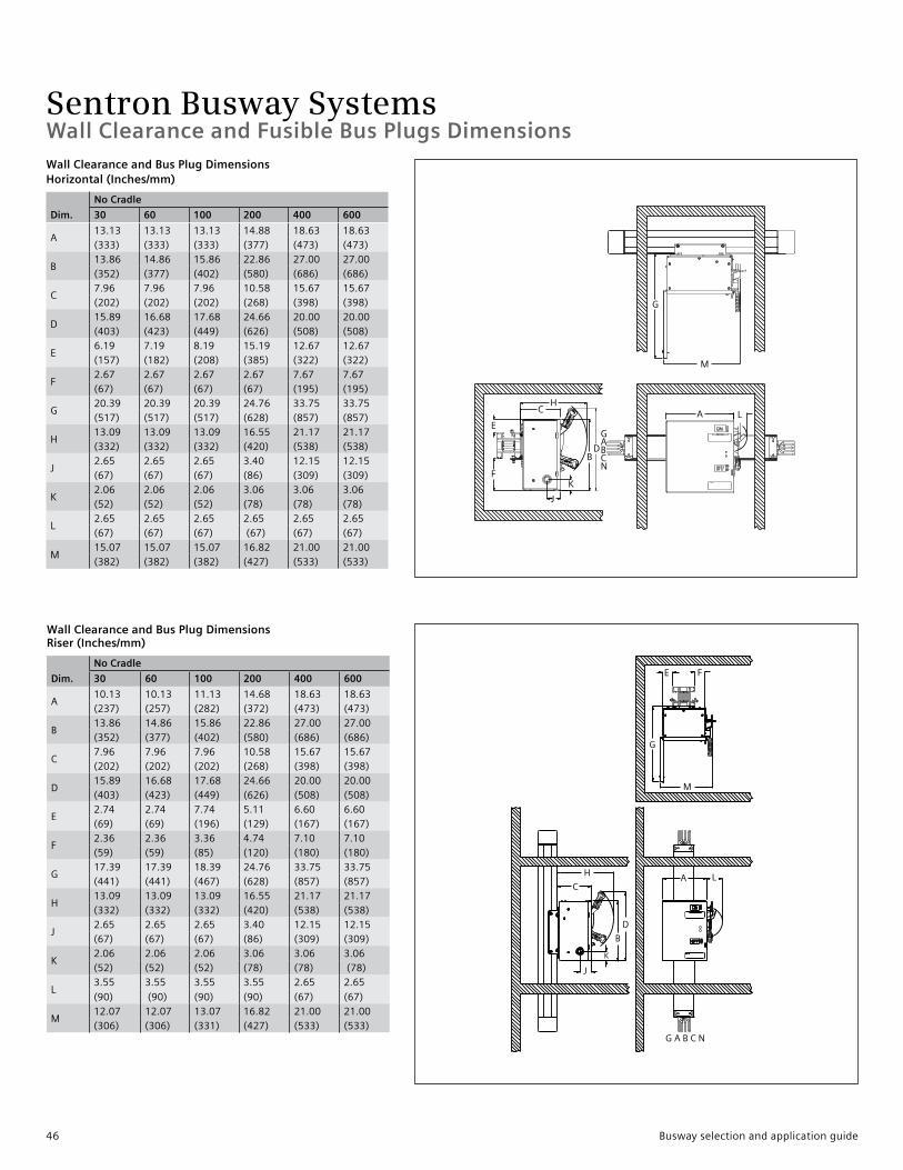
Sentron Busway SystemsWall Clearance and Fusible Bus Plugs Dimensions Wall Clearance and Bus Plug Dimensions Horizontal (Inches/mm)
Dim.
No Cradle
30 60 100 200 400 600
A13.13 13.13 13.13 14.88 18.63 18.63(333) (333) (333) (377) (473) (473)
B13.86 14.86 15.86 22.86 27.00 27.00(352) (377) (402) (580) (686) (686)
C7.96 7.96 7.96 10.58 15.67 15.67(202) (202) (202) (268) (398) (398)
D15.89 16.68 17.68 24.66 20.00 20.00(403) (423) (449) (626) (508) (508)
E6.19 7.19 8.19 15.19 12.67 12.67(157) (182) (208) (385) (322) (322)
F2.67 2.67 2.67 2.67 7.67 7.67(67) (67) (67) (67) (195) (195)
G20.39 20.39 20.39 24.76 33.75 33.75(517) (517) (517) (628) (857) (857)
H13.09 13.09 13.09 16.55 21.17 21.17(332) (332) (332) (420) (538) (538)
J2.65 2.65 2.65 3.40 12.15 12.15(67) (67) (67) (86) (309) (309)
K2.06 2.06 2.06 3.06 3.06 3.06(52) (52) (52) (78) (78) (78)
L2.65 2.65 2.65 2.65 2.65 2.65(67) (67) (67) (67) (67) (67)
M15.07 15.07 15.07 16.82 21.00 21.00(382) (382) (382) (427) (533) (533)
Wall Clearance and Bus Plug Dimensions Riser (Inches/mm)
Dim.
No Cradle
30 60 100 200 400 600
A10.13 10.13 11.13 14.68 18.63 18.63(237) (257) (282) (372) (473) (473)
B13.86 14.86 15.86 22.86 27.00 27.00(352) (377) (402) (580) (686) (686)
C7.96 7.96 7.96 10.58 15.67 15.67(202) (202) (202) (268) (398) (398)
D15.89 16.68 17.68 24.66 20.00 20.00(403) (423) (449) (626) (508) (508)
E2.74 2.74 7.74 5.11 6.60 6.60(69) (69) (196) (129) (167) (167)
F2.36 2.36 3.36 4.74 7.10 7.10(59) (59) (85) (120) (180) (180)
G17.39 17.39 18.39 24.76 33.75 33.75(441) (441) (467) (628) (857) (857)
H13.09 13.09 13.09 16.55 21.17 21.17(332) (332) (332) (420) (538) (538)
J2.65 2.65 2.65 3.40 12.15 12.15(67) (67) (67) (86) (309) (309)
K2.06 2.06 2.06 3.06 3.06 3.06(52) (52) (52) (78) (78) (78)
L3.55 3.55 3.55 3.55 2.65 2.65
(90) (90) (90) (90) (67) (67)
M12.07 12.07 13.07 16.82 21.00 21.00(306) (306) (331) (427) (533) (533)
46 Busway selection and application guide
Sentron Busway SystemsGeneral Information
Recommended Measurement Steps1.Usingsystemsrequirementsfor amperage,voltage,andconductors, determinethephysicalsizeofthe busway.Thisisimportantwhen settingminimumclearancesfrom walls,columns,ceilingsandother obstructions.Seepage30for minimalclearances.2.Priortoanylayout,reviewthe completeareatodeterminethe bestlocationfortherun.Special attentionneedstobegivento existingequipmentsuchas plumbing,HVAC,steelcolumns, beamsandpermanentstructures.3.Measurealldimensionsfromfixed pointssuchascolumns,walls,floors andceilings.4.Makeapreliminarysketchshowing proposedbuswayrouting,elevations andobstructions.Besuretoshow allfloorandwalllocations includingthickness.5.Whereplug-indevicesarebeing used,besuretoallowforproper operationclearances.Seedimensional requirementsshowninthebusplug sectionofthispublication.
Referencethefollowingdocumentsonlineatwww.usa.siemens.com/busway.• SentronQuickReference• BuswayOrderEntryChecklist• SentronBuswayInstallationand InstructionGuide
MaintenanceInordertomaintainsystemperformance,itisnecessarytoperformregularmaintenanceonyourbuswaysystem.SiemensStorage,InstallationandMaintenanceInstructions,andNEMAPublicationBU1.1shouldbeusedasaguidetopropermaintenanceprocedures.Routinemaintenanceofyourbuswaysystemwillincreaseitslifeandperformance.
Custom ProductWitha60yearhistoryindesigningandmanufacturingBuswaySystems,Siemenscandevelopcustomsolutionstomeetspecificjobrequirements.Siemensspecializesincustomengineeredbuswaysections,connections,andbusplugs.ConsultyourlocalSiemenssalesofficefordetailsoncustompricingandorderingConnecting to Existing EquipmentDoyouhaveexistingpowerdistributionequipment(non-Sentron)thatyouwouldliketorunSentronBuswaytoorfrom?SiemenscanengineerspecialconnectionpiecesthatallowyoutoconnectSentronBuswayquicklyandefficiently.
Transformer ConnectionsSiemenscanconnectSentronBuswaytoalmostanytransformer.AllyouneedtodoisprovidecompletedrawingsoftransformersecondaryconnectionswithdetaileddrillingpatternandphasinginformationtoyourlocalSiemenssalesengineerandtheycanorderyouacustomdesignedconnectionpiece.
PaintSentronBuswayproductshaveaprotectivefinishofANSI61gray(standard)polyesterurethanepowderpaint.Thepaintiselectrostaticallyappliedtoallhousingsurfaces.ColorsotherthanANSI61graymaybespecialordered.
LowCurrentDensityBuswaySentronBuswaymaybeorderedas1000A/in2Copperor750A/in2Aluminum.
Conversionisasfollows:
“L”Rating=750A/in2Aluminum“M”Rating=1000A/in2Copper1600“M”ratedisdedicatedoffering.
Required M or L Rating
AL L-Rated
225 —
400 —
600 —
800 400
1000 600
1200 800
1350 1000
1600 1200
2000 1350,1600
2500 2000
3000 2500
3200 2000
4000 3000,3200
Required M or L Rating
AL L-Rated
225 —
400 —
600 —
800 400
1000 —
1200 600
1350 800
1600 1000
2000 1200,1350
— 1600
2500 2000
3000 —
3200 —
4000 2500,3000
5000 4000
Busway selection and application guide 47
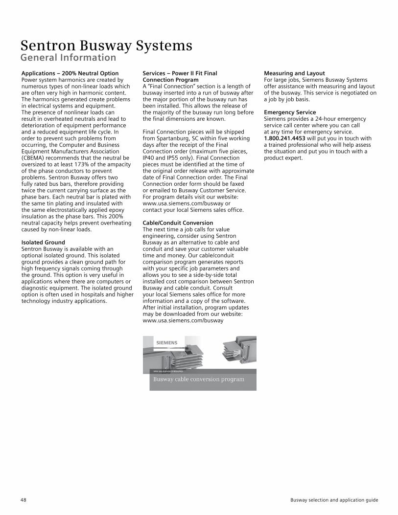
Sentron Busway Systems
Applications – 200% Neutral OptionPower system harmonics are created by numerous types of non-linear loads which are often very high in harmonic content. The harmonics generated create problems in electrical systems and equipment. The presence of nonlinear loads can result in overheated neutrals and lead to deterioration of equipment performance and a reduced equipment life cycle. In order to prevent such problems from occurring, the Computer and Business Equipment Manufacturers Association (CBEMA) recommends that the neutral be oversized to at least 173% of the ampacity of the phase conductors to prevent problems. Sentron Busway offers two fully rated bus bars, therefore providing twice the current carrying surface as the phase bars. Each neutral bar is plated with the same tin plating and insulated with the same electrostatically applied epoxy insulation as the phase bars. This 200% neutral capacity helps prevent overheating caused by non-linear loads.
Isolated GroundSentron Busway is available with anoptional isolated ground. This isolatedground provides a clean ground path for high frequency signals coming through the ground. This option is very useful in applications where there are computers or diagnostic equipment. The isolated ground option is often used in hospitals and higher technology industry applications.
Services – Power II Fit FinalConnection ProgramA “Final Connection” section is a length of busway inserted into a run of busway after the major portion of the busway run has been installed. This allows the release of the majority of the busway run long before the final dimensions are known.
Final Connection pieces will be shippedfrom Spartanburg, SC within five working days after the receipt of the Final Connection order (maximum five pieces, IP40 and IP55 only). Final Connection pieces must be identified at the time of the original order release with approximate date of Final Connection order. The Final Connection order form should be faxed or emailed to Busway Customer Service. For program details visit our website: www.usa.siemens.com/busway orcontact your local Siemens sales office.
Cable/Conduit ConversionThe next time a job calls for value engineering, consider using SentronBusway as an alternative to cable and conduit and save your customer valuable time and money. Our cable/conduit comparison program generates reports with your specific job parameters and allows you to see a side-by-side total installed cost comparison between SentronBusway and cable conduit. Consult your local Siemens sales office for more information and a copy of the software. After initial installation, program updates may be downloaded from our website:www.usa.siemens.com/busway
Measuring and LayoutFor large jobs, Siemens Busway Systemsoffer assistance with measuring and layout of the busway. This service is negotiated on a job by job basis.
Emergency ServiceSiemens provides a 24-hour emergencyservice call center where you can call at any time for emergency service. 1.800.241.4453 will put you in touch with a trained professional who will help assess the situation and put you in touch with a product expert.
General Information
Busway selection and application guide48
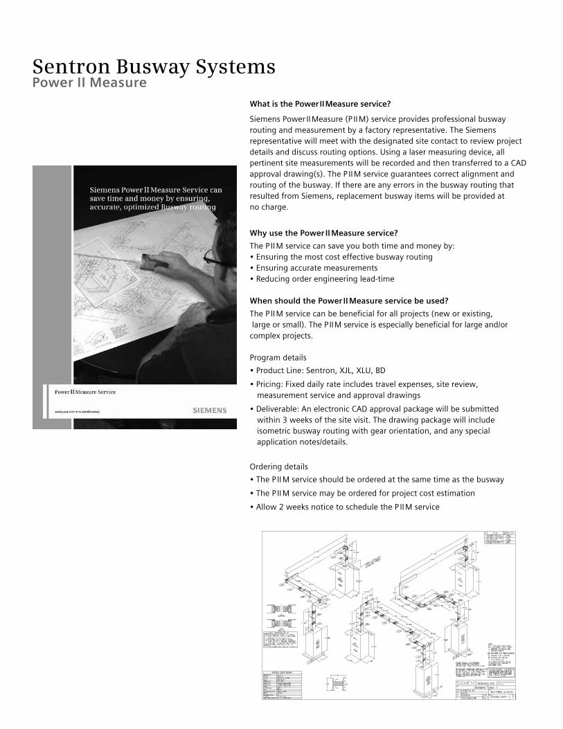
Sentron Busway Systems
What is the Power II Measure service?
Siemens Power II Measure (P II M) service provides professional busway routing and measurement by a factory representative. The Siemens representative will meet with the designated site contact to review project details and discuss routing options. Using a laser measuring device, all pertinent site measurements will be recorded and then transferred to a CAD approval drawing(s). The P II M service guarantees correct alignment and routing of the busway. If there are any errors in the busway routing that resulted from Siemens, replacement busway items will be provided at no charge.
Why use the Power II Measure service?
The P II M service can save you both time and money by:• Ensuring the most cost effective busway routing• Ensuring accurate measurements• Reducing order engineering lead-time
When should the Power II Measure service be used?
The P II M service can be beneficial for all projects (new or existing, large or small). The P II M service is especially beneficial for large and/or complex projects. Program details
• Product Line: Sentron, XJL, XLU, BD
• Pricing: Fixed daily rate includes travel expenses, site review, measurement service and approval drawings
• Deliverable: An electronic CAD approval package will be submitted within 3 weeks of the site visit. The drawing package will include isometric busway routing with gear orientation, and any special application notes/details.
Ordering details
• The P II M service should be ordered at the same time as the busway
• The P II M service may be ordered for project cost estimation
• Allow 2 weeks notice to schedule the P II M service
Power II Measure

Siemens Industry, Inc.5400 Triangle Parkway Norcross, GA 30092
1-800 [email protected] usa.siemens.com/busway
Subject to change without prior notice.Order No: BUSA-SENT1-1213All rights reserved.Printed in USA©2013 Siemens Industry, Inc.
The information provided in this brochure contains merelygeneral descriptions or characteristics of performancewhich in case of actual use do not always apply as describedor which may change as a result of further developmentof the products. An obligation to provide the respectivecharacteristics shall only exist if expressly agreed in theterms of contract.
All product designations may be trademarks or productnames of Siemens AG or supplier companies whose use bythird parties for their own purposes could violate the rightsof the owners.