Selecting a Screw Jack or Lifting Equipment – ProcedureCalcul_2010_GB.pdf · Selecting a Screw...
21
Selecting a Screw Jack or Lifting Equipment – Procedure Page 2 Observe design information R version Rotating spindle Page 5 Parameters according to Checklist Pages 1 to 5 Preselect screw jack size acc. to diagram on screw jack Pages Stat. / dyn. load (Section 4 - Catalogue 2008) Tension load Compression load Page 10 Buckling calculation Compression load Tension load Page 11 Critical whirling speed Page 10 Buckling calculation Preselect screw jack size acc. to diagram on screw jack Pages Stat. / dyn. load (Section 4 - Catalogue 2008) Min. spindle diameter (possibly select larger screw jack and check again) S version Standing spindle R S i Page 16 Check max. power torque (possibly select larger screw jack and check again) Page 12 Required drive torque per screw jack Page 14 System layout Define system components See Section 7 - Catalogue 2008 Page 17 Determine lengths (spindle, protective tube) Page 21 Order code Page 14 Select motor Min. spindle diameter (possibly select larger screw jack and check again) INFO: Please always confirm the application parameters, load, speed, duty etc. so we can confirm the correct components have been selected. F © by ZIMM Austria 2009 1 Selection - Checklists - Calculations
Transcript of Selecting a Screw Jack or Lifting Equipment – ProcedureCalcul_2010_GB.pdf · Selecting a Screw...

Selecting a Screw Jack or Lifting Equipment – Procedure
Page 2 Observe design information
R versionRotating spindle
Page 5 Parameters according to Checklist Pages 1 to 5
Preselect screw jack sizeacc. to diagram on screw jack Pages
Stat. / dyn. load (Section 4 - Catalogue 2008)
Tensionload
Compressionload
Page 10 Bucklingcalculation
Compressionload
Tensionload
Page 11 Criticalwhirling speed
Page 10 Bucklingcalculation
Preselect screw jack sizeacc. to diagram on screw jack Pages
Stat. / dyn. load (Section 4 - Catalogue 2008)
Min.spindle diameter
(possibly select larger screw jackand check again)
S versionStanding spindle RS
i
Page 16 Check max.
power torque(possibly select larger screw jack
and check again)
Page 12 Required drive torqueper screw jack
Page 14 System layout
Define system componentsSee Section 7 - Catalogue 2008
Page 17 Determine lengths(spindle, protective tube)
Page 21 Order code
Page 14 Select motor
Min.spindle diameter
(possibly select larger screw jackand check again)
INFO:Please always confirm the
application parameters, load,
speed, duty etc. so we can
confirm the correct
components have been
selected.
F
© by ZIMM Austria 20091
Selection - Checklists - Calculations

© by ZIMM Austria 20092
Selection - Checklists - Calculations
Parallelism and angularity
Pay attention to the parallelism andangularity of mounting surfaces, gears,nuts and guides to each other. The sameapplies for exact alignment of gears,pedestal bearings, connecting shafts andmotors to each other.
GuidesGuide bush play inthe screw jack gear-box can be between0.2 mm and 0.6 mm depending on thesize. This is just asecondary supportand does not re-place a linear guidesystem to supportside forces.
- Frequency converter: Serves to increase the motor speed to above 1500. This variant is only usable for movements without load or with light loads.
Slower:- Motors with more poles/lower speed
(6, 8, 10 or 12 poles)- Frequency converter (attention:
a suitable cooler for the motor is required for slow operation below 25 Hz, e.g.: external fan)
- Geared motor (attention: maximum input torque)
- Bevel gearbox with gear reduction (only possible for certain applications)
Temperature and operating periodScrew jacks are generally not designed for continuous operation.Refer to the diagram on the Gearbox Pages (Section 4 - Catalogue 2008) for the maximum #ope-rating periods (ED). These are reference values but variousaccording to usage conditions. In borderline cases, select a larger screwjack or contact our project technicians.Operating temperatures should notexceed 80°C (higher on request).
Rotation protectionOn the Version S with standing spindle,the spindle is free running within the gear(worm wheel). The spindle must be pro-tected against rotation – otherwise itwould rotate due to the friction in theworm wheel. This can be achieved byfixing the spindle to an external guidancesystem or by using our rotation protection(VS) (in a protective tube).
Design and specificationThe customer confirm selection anddimensioning because we are not familiarwith the design criteria such as installa-tion location and type of application. Wecan provide support during selection andlayout on request and make a proposalwith subassemblies drawing and calcula-tion based on your application parame-ters. You can then examine and approvethis drawing with parts lists. These thenserve as basis for production and pre-assembly and assist your employeesduring assembly and fitting. We guaran-tee the quality of the machine elementsas described in the catalogue. The gear-boxes are designed for industrial use withloads and operating periods as specified inthe catalogue.
Please contact our project technicians fordemands going beyond these specifica-tions. We generally deliver according toour current Terms of Sales and Delivery(Section 10 - Catalogue 2008).
Lifting speed
Several options are available to in-fluence the lifting speed:
Faster:- Double-pitch screw (not generally in
stock): Doubles the speed (attention: max. input torque, not self-locking -brake required!)
- Larger spindle diameter for R version(spindle from next larger size): Bigger pitch / higher lifting speed depending on gearbox size
- Ball screw spindle: Various pitch optionsavailable (attention: not self-locking,brake required!)
Construction Advice i
m/minV
Lifting speed v =Spindle pitch P Gear reduction i
x motor speed n
© by ZIMM Austria 20093
Selection - Checklists - Calculations
Direction of rotation and movement
Check the rotation direction of the equipment and record this in the drawingor select one of our standard system layouts (Section 4 - Catalogue 2008). With T bevel gearboxes, the direction ofrotation can be changed by simply turning the gearbox around.
Self-locking / overrunScrew jacks with a single pitch trapezoidthread spindles have a limited self-lockingcapability which cannot always be reliedupon, especially with impact loads orvibrations (brake recommended).
The overrun after the motor has beenswitched off varies depending on theapplication. To minimize overrun, werecommend using a brake motor or aspring-compression brake FDB. A brakedmotor is essential for double pitch spindles or ball screw drives because these are not self-locking.
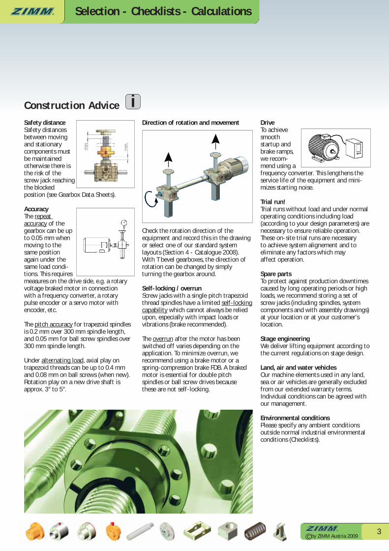
Safety distanceSafety distancesbetween movingand stationarycomponents mustbe maintainedotherwise there isthe risk of thescrew jack reachingthe blocked position (see Gearbox Data Sheets).
AccuracyThe repeat accuracy of thegearbox can be upto 0.05 mm whenmoving to thesame positionagain under thesame load condi-tions. This requires measures on the drive side, e.g. a rotaryvoltage braked motor in connection with a frequency converter, a rotary pulse encoder or a servo motor withencoder, etc.
The pitch accuracy for trapezoid spindlesis 0.2 mm over 300 mm spindle length,and 0.05 mm for ball screw spindles over300 mm spindle length.
Under alternating load, axial play on trapezoid threads can be up to 0.4 mmand 0.08 mm on ball screws (when new).Rotation play on a new drive shaft isapprox. 3° to 5°.
Drive To achievesmooth startup andbrake ramps,we recom-mend using afrequency converter. This lengthens theservice life of the equipment and mini-mizes starting noise.
Trial run!Trial runs without load and under normaloperating conditions including load(according to your design parameters) arenecessary to ensure reliable operation. These on-site trial runs are necessary to achieve system alignement and to eliminate any factors which may affect operation.
Spare partsTo protect against production downtimescaused by long operating periods or highloads, we recommend storing a set ofscrew jacks (including spindles, systemcomponents and with assembly drawings)at your location or at your customer'slocation.
Stage engineeringWe deliver lifting equipment according tothe current regulations on stage design.
Land, air and water vehiclesOur machine elements used in any land,sea or air vehicles are generally excludedfrom our extended warranty terms. Individual conditions can be agreed withour management.
Environmental conditionsPlease specify any ambient conditionsoutside normal industrial environmentalconditions (Checklists).
Construction Advice i
Selection - Checklists - Calculations
© by ZIMM Austria 20094
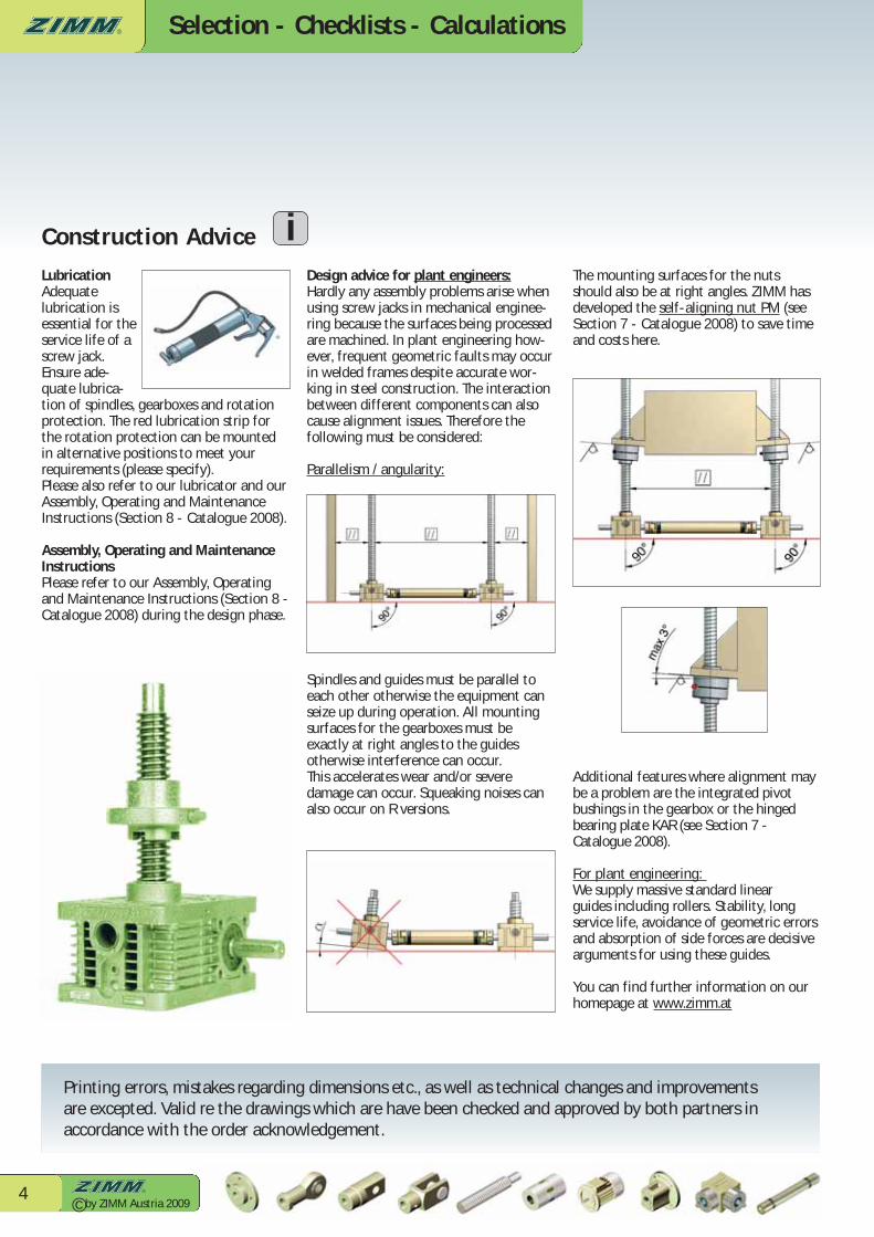
The mounting surfaces for the nutsshould also be at right angles. ZIMM hasdeveloped the self-aligning nut PM (seeSection 7 - Catalogue 2008) to save timeand costs here.
Additional features where alignment maybe a problem are the integrated pivotbushings in the gearbox or the hingedbearing plate KAR (see Section 7 - Catalogue 2008).
For plant engineering: We supply massive standard linear guides including rollers. Stability, longservice life, avoidance of geometric errorsand absorption of side forces are decisivearguments for using these guides.
You can find further information on ourhomepage at www.zimm.at
LubricationAdequate lubrication isessential for theservice life of ascrew jack.Ensure ade-quate lubrica-tion of spindles, gearboxes and rotationprotection. The red lubrication strip forthe rotation protection can be mountedin alternative positions to meet your requirements (please specify). Please also refer to our lubricator and ourAssembly, Operating and MaintenanceInstructions (Section 8 - Catalogue 2008).
Assembly, Operating and MaintenanceInstructionsPlease refer to our Assembly, Operatingand Maintenance Instructions (Section 8 -Catalogue 2008) during the design phase.
Design advice for plant engineers:Hardly any assembly problems arise whenusing screw jacks in mechanical enginee-ring because the surfaces being processedare machined. In plant engineering how-ever, frequent geometric faults may occurin welded frames despite accurate wor-king in steel construction. The interaction between different components can alsocause alignment issues. Therefore the following must be considered:
Parallelism / angularity:
Spindles and guides must be parallel toeach other otherwise the equipment canseize up during operation. All mountingsurfaces for the gearboxes must be exactly at right angles to the guidesotherwise interference can occur. This accelerates wear and/or severe damage can occur. Squeaking noises can also occur on R versions.
Printing errors, mistakes regarding dimensions etc., as well as technical changes and improvements are excepted. Valid re the drawings which are have been checked and approved by both partners in accordance with the order acknowledgement.
Construction Advice i

Selection - Checklists - Calculations
© by ZIMM Austria 20095
Company: Date:
Address: Phone:
Contact: Fax:
Dept.: E-mail:
1 Lifting force in kN, max.- Per gearbox kN Per system kN- Under tension kN Under compression kN- Load: static kN Dynamic kN- Fitting posn.: vertical horizontal pivotal- Conditions: smooth impact load vibrations
2 Lift / travel mm
3 Lifting speedType N = 1.5 m/min Type L = 0.375 m/min Customer requirement m/min (many variants possible)
4 Operating period, operating cycle lifts per day lifts per hour hours per day: 8 16 24 % operating period (ED) relative to 10 min,
For ED > 10 % per 10 min, please specify cycle (e.g.: 5s up, 5s pause, 5s down, 30s pause)
5 Type S or R: S standing spindle R rotating spindle
6 Standard layout No. Measure MA1 MA2 MA3 MA4 MA5See standard layouts, Checklist Page 8 and 9 (for multiple systems)
7 Component list YES NO See Checklist Page 6 or 7!
8 Motor: Rotary voltage motor AC Brake motor AC Manual operationSpring-compression brake Incremental encoder Linear measuring system Limit switches (S version)
9 Application purpose / function description / branch
Operating conditions: Dry Humid Dusty Chips Ambient temperature: Min. °C Max. °C
10 Quantity: pcs. Prototype first
11 Schedule: Quotation: Delivery:
Description:
Fast and efficient:
Copy
Select
Fax / E-mail
Checklists - Page 1 - Parameters

Selection - Checklists - Calculations
© by ZIMM Austria 20096
Checklists - Page 2 - Component List S
Tension load (kN), static
Tension load (kN), dynamic
Compression load (kN), static
Compression load (kN), dynamic
Standard spindle end
Fixing flange BF
Pivot bearing head SLK
Forked head GK
Rod end KGK
Bellows FB
Spiral spring SF
Handwheel HR
Motor with brakeMotor without brake
Coupling KUZ
Rotary pulse encoder DIG
Motor flange MF
Pivot bracket LB
Hinged bearing plate KAR
Lubricator Z-LUBSpring-compression brake FDB
Protective cap SKLubrication strip SL
2x limit switch set ESSET
Rotation protection VS
Escape protection ASProtective tube SRO
Stro
ke
Type:SN (standing spindle, normal speed)SL (standing spindle,low speed )
Variants:Tr trapezoidal screw SIFA safety nut
with SIFA control
This pictureshows variousoptions!
KGT ball screw
Selection - Checklists - Calculations
© by ZIMM Austria 20097
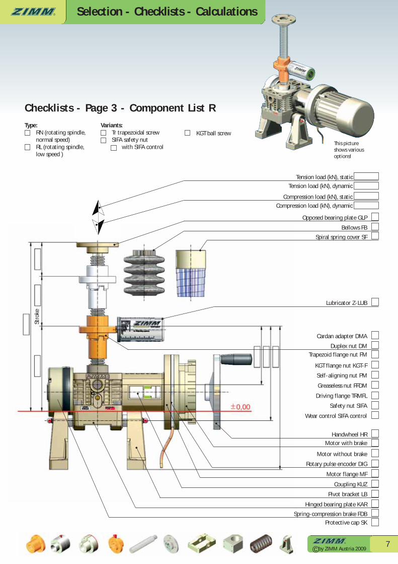
Checklists - Page 3 - Component List R
This pictureshows variousoptions!
Tension load (kN), static
Tension load (kN), dynamic
Compression load (kN), static
Compression load (kN), dynamic
Opposed bearing plate GLP
Bellows FB
Spiral spring cover SF
Lubricator Z-LUB
Cardan adapter DMA
Duplex nut DMTrapezoid flange nut FM
KGT flange nut KGT-F
Self-aligning nut PM
Greaseless nut FFDM
Driving flange TRMFL
Safety nut SIFA
Wear control SIFA control
Handwheel HRMotor with brake
Motor without brake
Rotary pulse encoder DIG
Motor flange MF
Coupling KUZ
Pivot bracket LB
Hinged bearing plate KAR
Spring-compression brake FDBProtective cap SK
Stro
ke
Type:RN (rotating spindle, normal speed)RL (rotating spindle,low speed )
Variants:Tr trapezoidal screw SIFA safety nut
with SIFA control
KGT ball screw
Selection - Checklists - Calculations
© by ZIMM Austria 20098
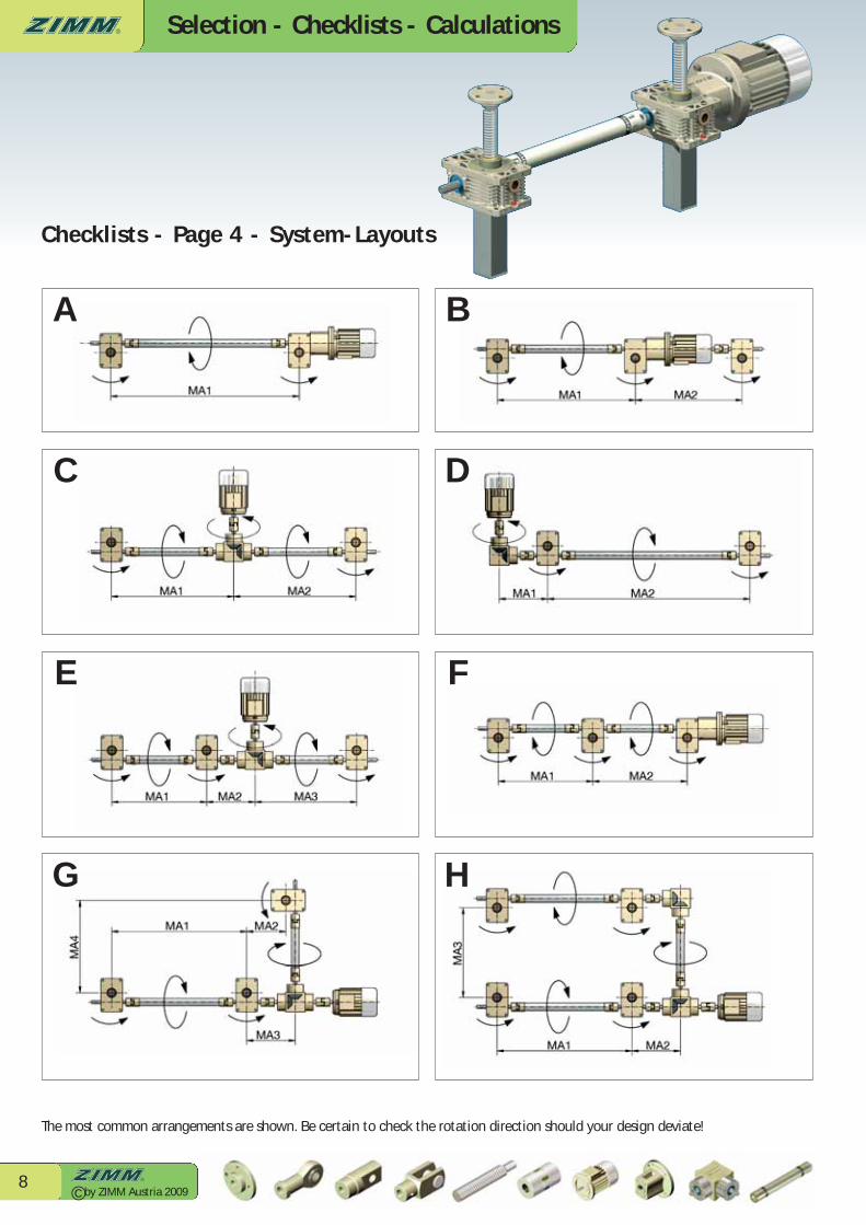
Checklists - Page 4 - System-Layouts
A
C
E
G
B
D
F
H
The most common arrangements are shown. Be certain to check the rotation direction should your design deviate!

Selection - Checklists - Calculations
© by ZIMM Austria 20099
Checklists - Page 5 - System-Layouts
i
K
M
J
L
N
The most common arrangements are shown. Be certain to check the rotation direction should your design deviate!

Selection - Checklists - Calculations
© by ZIMM Austria 200910
Z-2 Z-5 Z-10 Z-25 Z-35/50 Z-50/Tr50 Z-100 Z-150 Z-250 Z-350 Z-500 Z-750 Z-1000Trapezoid thread Tr 16x4 18x4 20x4 30x6 40x7 50x8 55x9 60x9 80x16 100x16 120x16 140x20 160x20Core Ø in mm (minimum) 10.9 12.9 14.9 22.1 31.0 39.8 43.6 48.6 59.6 80.6 99.6 115.0 135.0
Ball screw KGT Ø mm 16 16 25 32 40 - 50 63 80 - - - -Core Ø in mm (minimum) 12.9 12.9 21.5 27.3 34.1 - 44.1 57.1 72.4 - - - -
F
I = = 55,610.7396 mm445,000 N x 3 x (1,320 mm x 0.7)2
π2 x 210,000 N/mm2
1.1525912 mm4
2,072,616.924=
Critical Buckling Force of the Spindle
Example:
I = then d =F x v x (L x 2)2
π2 x EI x 64π
4
I = = 453,965.22 mm445,000 N x 3 x (1,320 mm x 2)2
π2 x 210,000 N/mm2
9.4089611 mm4
2,072,616.924
d = = 55.15 mm minimum core diameter= Z-250 (spindle core Ø = 59.6 mm)
453,965.22 mm4 x 64π
4
I = then d =F x v x L2
π2 x EI x 64π
4
d = = 38.99 mm minimum core diameter= Z-100 (spindle core Ø = 43.6 mm)
113,491.305 mm4 x 64π
4
I = then d =F x v x (L x 0.7)2
π2 x EI x 64π
4
d = = 32.62 mm minimum core diameter= Z-50/Tr50 (spindle core Ø = 39.8 mm)
55,610.739 mm4 x 64π
4
F = 45,000N/gearboxL = 1320 mmv = 3
Explanation:I = moment of area 2nd level in mm4
F = max. load/gearbox in N L = free spindle length in mm E = elasticity modulus for steel (210,000N/mm2) v = safety factor (normally 3)d = minimum core diameter of spindle
Formula:
Example:
Formula:
Example:
Formula:
Example:
=
I = = 113,491.305 mm445,000 N x 3 x (1,320 mm)2
π2 x 210,000 N/mm2
2.3522411 mm4
2,072,616.924=
Euler 1
Unguided
S versionGuided
Pivot drive
Euler 2
R versionGuided
Euler 3

Selection - Checklists - Calculations
© by ZIMM Austria 200911
Critical Whirling Speed for R Gearboxes
The maximum allowable spindle speedmust be calculated for R version gear-boxes (with rotating spindle) with long,thin spindles. To do this, read out the theoretical critical speed nkr from the diagram. Also consider the additionallengths for spindle bellows etc. when calculating the unsupported spindlelengths. Now use the formula togetherwith the correction factor for the spindle mounting to calculate the maximum allowable spindle speed.
If the calculated maximum spindle speedis lower than the required speed, select alarger spindle or a double pitch spindlewith half the speed. This must then bechecked. You have the option to use a"stronger spindle" on the R version (spindle of next larger gearbox).
Bear in mind that a larger diameter spindle demands a higher drive torque.
Attention:Long, thin spindles can squeak even though the bending critical speed ismaintained! Therefore calculate with sufficient safety margins.
Maximum allowable spindle speednzul = 0.8 x nkr x fkr
With end mounting(preferred solution)
Without end mounting(avoid when possible)
Input speed
iGearbox
Spindle speed =
f kr=
1
f kr=
0,32
0
100
200
300
400
500
600
700[rpm]
1500 2000 2500 3000 3500 4000 4500 5000Unsupported spindle length [mm]
Tr 18x4Tr 20x4
Tr 30x6
Tr 40x7Tr 55x9Tr 60x9
Tr 80x16
Tr 100x16
Tr 120x16
Tr 140x20
Tr 160x20
nzul Maximum allowable spindle speed (rpm)
nkr Theoretical critical spindle speed (rpm)that leads to resonance vibrations (see diagram)
fkr Correction factor that considers the type of spindle mounting
The operating speed must not exceed 80% of the maximum speed!
nkr
Tr 16x4

Selection - Checklists - Calculations
© by ZIMM Austria 200912
ZNL
20.080.06
50.100.08
100.260.16
250.360.26
350.560.40
500.760.54
1001.681.02
1501.901.20
2502.641.94
3503.242.20
5003.962.84
7507.284.42
10009.705.90
For gearboxes with single pitch trapezoid thread spindles, it is also possible to just multiply the load by the factor stated on thecorresponding gearbox page (Section 4 - Catalogue 2008).
Determining the Drive Torque of [MG] One Screw Jack
MG Required drive torque [Nm] for a gearboxF Lifting load (dynamic) [kN] ηGearbox Screw jack efficiency (without spindle)ηSpindle Spindle efficiencyP Spindle pitch [mm] i Screw jack ratioML Idling torque [Nm]PM Motor drive capacity
i rpm Z-2 Z-5 Z-10 Z-25 Z-35 Z-50 Z-100 Z-150 Z-250 Z-350 Z-500 Z-750 Z-1000N 3000 0.87 0.81 0.83 0.87 - - - - - - - - -N 1500 0.87 0.82 0.84 0.87 0.87 0.87 0.88 0.89 0.91 0.91 0.93 - -N 1000 0.86 0.82 0.82 0.86 0.87 0.86 0.87 0.89 0.90 0.91 0.92 0.88 0.90N 750 0.86 0.82 0.84 0.85 0.86 0.85 0.87 0.88 0.90 0.91 0.92 0.88 0.90N 500 0.85 0.82 0.84 0.83 0.85 0.84 0.85 0.87 0.89 0.90 0.92 0.87 0.89N 100 0.74 0.77 0.79 0.78 0.78 0.78 0.78 0.80 0.83 0.86 0.87 0.81 0.84L 3000 0.78 0.74 0.78 0.76 - - - - - - - - -L 1500 0.77 0.70 0.74 0.72 0.64 0.66 0.67 0.67 0.78 0.79 0.77 - -L 1000 0.75 0.67 0.72 0.70 0.64 0.66 0.65 0.66 0.77 0.78 0.76 0.67 0.76L 750 0.74 0.65 0.70 0.68 0.64 0.66 0.65 0.65 0.76 0.78 0.75 0.66 0.76L 500 0.71 0.62 0.67 0.65 0.63 0.65 0.65 0.63 0.75 0.77 0.73 0.65 0.75L 100 0.54 0.53 0.59 0.54 0.52 0.55 0.57 0.53 0.65 0.67 0.61 0.58 0.66
The following specifications serve tocalculate the required drive torque. In order to facilitate calculation of thedrive torque, we have determined multiplication factors from this formulaand included these in the technical datafor the respective versions.
Tr spindle, single pitch 16x4 18x4 20x4 30x6 40x7 50x8 55x9 60x9 80x16 100x16 120x16 140x20 160x20 Ball screw spindleEfficiency 0.453 0.420 0.391 0.391 0.357 0.335 0.340 0.320 0.391 0.335 0.293 0.308 0.278 0.9Tr spindle, double pitch 16x8P4 18x8P4 20x8P4 30x12P6 40x14P7 50x16P8 55x18P9 60x18P9 80x32P16 100x32P16 120x32P16 140x40P20 160x40P20 Ball screw spindleEfficiency 0.623 0.591 0.563 0.563 0.526 0.502 0.508 0.484 0.563 0.502 0.453 0.471 0.436 0.9
Gearbox efficiency ηGearbox (without spindle)
Spindle efficiency ηSpindle
Idling torque ML of gearbox [Nm] (without spindle, at 20°C)
Formula: Example:
1) Drive torque: MG = + ML [Nm]F [kN] . P [mm]
2 . π . ηGearbox . ηSpindle
. i
MG [Nm] . n [min-1]
9550
1) MG = + 0.36 Nm = 6.21 Nm12 kN . 6 mm
2 . π . 0.87 . 0.375 . 6
2) PM = = 0.975 kW6.21 Nm . 1500 min-1
9550
3) Example: 0.975 kW . 1.5 = 1.462 kW Motor 1.5 kW3) We recommend multiplying the calculatedvalue by a safety factor of 1.3 to 1.5 (up to 2 forsmall systems).
Z-25-SN F = 12 kN (lifting load, dynamic)ηGearbox = 0.87 ηSpindle = 0.375P = 6 i = 6
!2) Motor capacity: PM[kW] =

Selection - Checklists - Calculations
© by ZIMM Austria 200913
Drive Torque for Gearboxes - exact calculationThe efficiency of connecting shafts (η 0.95) and bevel gearboxes (η 0.90) are included in the following example calculation.
1
1
2
2
3
3
4
5
67
Drive torque: MG = + ML [Nm]F [kN] . P [mm]
2 . π . ηGearbox . ηSpindle
. i
Example:
1) MG = + 0.36 Nm = 6.21 Nm12 kN . 6 mm2 . π . 0.87 . 0.375 . 6
3) 6.21 Nm + 6.53 Nm = 12.74 Nm 12.74 Nm . 1.5 = 19.11 Nm--> This means KSZ-25-L is OK (see Section 6 -Catalogue 2008)
46 Nm --> we need KSZ-50-L(see Section 6 - Catalogue 2008)
Motor selection: 132M-P4-7.5 kW (50 Nm)--> see Section 7 - Catalogue 2008 for motors
Z-25-SNF = 12 kN (lifting load, dynamic per gearbox)ηGearbox = 0.87 ηSpindle = 0.375P = 6 i = 6
Gearbox formula:
Efficiency:Connecting shafts: η 0.95Bevel gearboxes: η 0.90
2) = 6.53 Nm6.21 Nm0.95
(Connecting shaft efficiency)
4) = 14.15 Nm12.74 Nm0.9
(Bevel gearbox efficiency)
5) = 14.9 Nm14.15 Nm0.95
6) (12.74 Nm + 14.9 Nm)/0.9 = 30.71 Nm
7) 30.71 Nm . 1.5 = 46 Nm
We recommend multiplying the calculatedvalue by a safety factor of 1.3 to 1.5 (up to 2for small systems). !
An approximated calculation is shown on the next page.
Selection - Checklists - Calculations
© by ZIMM Austria 200914
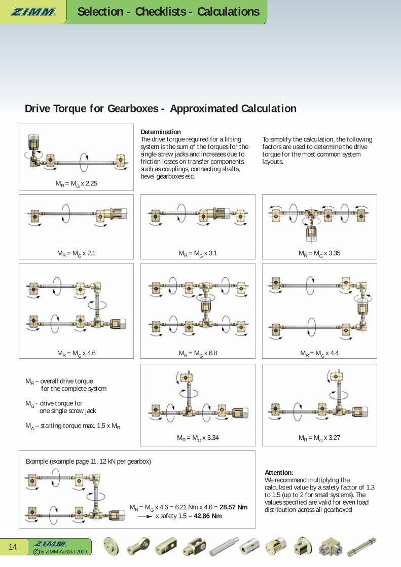
Drive Torque for Gearboxes - Approximated Calculation
Attention:We recommend multiplying the calculated value by a safety factor of 1.3to 1.5 (up to 2 for small systems). Thevalues specified are valid for even loaddistribution across all gearboxes!
MR – overall drive torquefor the complete system
MG - drive torque forone single screw jack
MA – starting torque max. 1.5 x MR
Example (example page 11, 12 kN per gearbox)
MR = MG x 4.6 = 6.21 Nm x 4.6 = 28.57 Nm x safety 1.5 = 42.86 Nm
MR = MG x 2.25
MR = MG x 2.1 MR = MG x 3.1 MR = MG x 3.35
MR = MG x 4.6 MR = MG x 6.8 MR = MG x 4.4
MR = MG x 3.34 MR = MG x 3.27
DeterminationThe drive torque required for a liftingsystem is the sum of the torques for thesingle screw jacks and increases due tofriction losses on transfer componentssuch as couplings, connecting shafts,bevel gearboxes etc.
To simplify the calculation, the followingfactors are used to determine the drive torque for the most common system layouts.

© by ZIMM Austria 200915

Selection - Checklists - Calculations
© by ZIMM Austria 200916
Maximum Forces / Torques
Side forces on the lifting screwThe Table on the right shows the maximum allowable side forces. Sideforces should generally be supported by linear slides. The guide bushing inthe gearbox only functions as a secondary guide. The maximum sideforces actually effective must be below the Table value!
Attention: Only static allowed
Maximum input torqueThe values shown should not be exceeded to attain the optimal servicelife. Higher values for lower operatinghours are possible. Please provide full data.
Radial load on the input shaftThe radial forces in the adjacent Tableshould not be exceeded when usingchain or belt drives.
FS
F
FR
FAMR
nR
Input shaft=worm shaft
Load definitionsF - Lifting load tension and/or compressionFS - Side forces on the spindlevH - Lifting speed of the spindle
(or nut on R versions)FA - Axial load of the input shaftFR - Radial load of the input shaftMR - Input torquenR - Input speed
Please examine the information on the following technical pages beforemaking your choice of the appropriate screw jack. A full specification canonly be given with full application data and relevant information. In case of doubt, please contact our project technicians.
Z-5 Z-10 Z-25 Z-35 Z-50 Z-100 Z-150 Z-250 Z-350 Z-500 Z-750 Z-1000FR max. 110 190 260 260 420 650 670 1100 1400 2600 3000 3400
200160280470700
200040005000900013000290003480046000
1003606009001300300050005500900015000290003480046000
Z5102535501001502503505007501000
300100180300450130030003900650012000290003480039000
40070
13024036090023002800490010000290003480036000
50055100180270700
1800230038008800290003480032000
60045801502206001500180030007000
240002880030000
7003870
1301905001300150025006000200002400025000
80032601101604201100130022005500170002040029000
9002850100150380950120020004800150001800025000
1000254790130330850100019004300140001680023500
120020407010028070085014503500120001440020000
1500183060902306007501250300090001080017000
20001220456016040050090020007000840012000
2500–15355013035040076016005600672010000
3000––30401002503506601400490058808000
i rpm Z-5 Z-10 Z-25 Z-35 Z-50 Z-50/Tr50 Z-100 Z-150 Z-250 Z-350 Z-500 Z-750 Z-1000N 3000 4.0 11.0 17.0 - - - - - - - - - -N 1500 4.7 13.5 18 19.8 31.5 31.5 53.4 75.1 152 - - - -N 1000 5.6 14 22 20.8 36.8 36.8 60.8 77.1 152 265 408 480 680N 500 6.1 16.7 28 24.8 46.5 46.5 75.3 95 160 350 500 640 960L 3000 1.4 5.7 8.5 - - - - - - - - - -L 1500 1.5 7.5 10 9 10.4 10.4 13.5 20.7 41.4 - - - -L 1000 1.8 8.7 11 9.7 14.9 14.9 15.4 23.7 47.4 100 170 210 450L 500 2.2 10.7 14 11.1 19.2 19.2 18.9 29.4 63.5 112 220 240 580Drive-through 39 57 108 130 260 260 540 540 770 1800 1940 4570 4570
Maximal side force FS [N] (only static) Extended spindle length in mm
- Bear in mind that the starting torque is approx. 1.5 times the operating torque- Limit values are mechanical - consider thermic factors depending on operating period
Maximum input torque MR [Nm] Max. drive-through torque, worm shaft [Nm]
Maximum radial load of the input shaft FR [N]

Selection - Checklists - Calculations
© by ZIMM Austria 200917
Fitting lenghtThe following Tables serve to calculate the required spindle and protective tubeextension lengths yourself. This lets youquickly calculate the fitting dimensions of your screw jack.
Basic principleThe spindle (and the protective tube onthe S version) are extended depending onthe version and system components used. These dimensions are minimum requirements. For special fitting situations, please provide a drawing orcontact our project technicians.
Stroke + basic length (+ various extensions for variants/system components)
Example S:Z-25-SN, stroke: 250 mmBellows Z-25-FB-300 (ZD=70 mm)Fixing flange BF (therefore bellows without fixing ring)Rotation protection VSLimit switch ESSET
Spindle length Tr:
250 + 180 + 44 + 45 = 519 mmStroke Basic length Bellows Limit switch Spindle length
(70-26=44) + rotation protectionSection 7 - Catalogue 2008
Protective tube length SRO:250 + 53 + 72 = 377
Stroke Basic length Limit switch + Protective tube lengthRotation protection
Example R:
Z-25-RN, stroke 250 mmSpindle with journal (opposed bearing plate GLP)Bellows Z-25-FB-300 (ZD=70 mm) below and aboveDuplex nut DM
Spindle length Tr:250 + 139 + 60 + 55 + 50 = 554 mm
Stroke Basic length Bellows, gearbox side 2nd bellows Duplex nut Spindle length(70-10=60) (70-15=55)
Length calculation for connecting shafts can be found in Section 7 - Catalogue 2008.
Calculating Spindle and Protective Tube Lengths
Selection - Checklists - Calculations
© by ZIMM Austria 200918
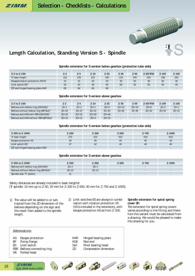
1) The value will be added to or sub-tracted from the ZD dimension of the bellows depending on the sign and the result then added to the spindle length.
Length Calculation, Standing Version S - Spindle
Z-2 to Z-150:Tr basic lengthEscape/rotation protection AS/VSLimit switch ES2)
ES2) and hinged bearing plate KAR
Abbreviations:
AS Escape protection KAR Hinged bearing plateBF Fixing flange KGK Rod endES Limit switch SLK Pivot bearing headFBR Bellows connecting ring ZD Compression dimensionGK Forked head
Safety distances are already included in basic lengths!(Tr spindle: 10 mm up to Z-50, 20 mm for Z-100 to Z-500, 40 mm for Z-750 and Z-1000)
2) Limit switches ES are always in combi-nation with rotation protection VS (VS is included in the extension), with escape protection AS as from Z-250.
Spindle extension for spiral spring cover SF: The extension for spiral spring coversvaries according to the fitting and there-fore this variant must be calculated froma drawing. We would be pleased to makethis drawing for you.
Spindle extension for S version below gearbox (protective tube side)
Z-2118154365
Z-5139154364
Z-10161204565
Z-25180204569
Z-352193059-
Z-502403055-
Z-50/Tr502633055-
Z-1003383045-
Z-1503423045-
Spindle extension for S version above gearbox
Z-2ZD-1ZD-18ZD+32ZD+15
Z-5ZD-2ZD-22ZD+31ZD+11
Z-10ZD+1ZD-24ZD+28ZD+3
Z-25ZD+5ZD-26ZD+46ZD+15
Z-35ZD+10ZD-36
--
Z-50ZD+10ZD-36
--
Z-50/Tr50ZD+8ZD-40
--
Z-100ZD-2
ZD-50--
Z-150ZD-2ZD-22
--
Z-250 to Z-1000:Tr basic lengthEscape protection ASLimit switch ES2)
ES2) and hinged bearing plate KAR
Spindle extension for S version below gearbox (protective tube side)
Z-2503703037-
Z-3504243542-
Z-5005524040-
Z-7506194040-
Z-10006434040-
Spindle extension for S version above gearbox
Z-250ZD-2ZD-22
11
Z-350ZD-2ZD-22
-
Z-500---
Z-750---
Z-1000---
Z-2 to Z-150:Bellows with bellow ring (GK/KGK)1)
Bellows without bellow ring (BF/SLK)1)
Bellows and KAR with FBR (GK/KGK)1)
Bellows and KAR without FBR (BF/SLK)1)
Z-250 to Z-1000:Bellows with bellow ring (GK/KGK)1)
Bellows without bellow ring (BF/SLK)1)
Spindle side ”F” (down)

Selection - Checklists - Calculations
© by ZIMM Austria 200919
Length Calculation, Standing Version S - Protective Tube SRO
1) Basic length of protective tube without cap - add another 5 mm to the overall length of the protective tube to include the
cap thickness.2) If a shorter stroke than specified is
required, fit the limit switches and the lubrication strip on two different sides (fitting location)!
3) Limit switches ES are always in combination with rotation protectionVS (VS is included in the extension), with escape protection AS as from Z-250.
Protective tube extension for S version
Z-247157092
Z-546157394
Z-1049207292
Z-2553207296
Z-35573086-
Z-50623082-
Z-50/Tr50623082-
Z-100823062-
Z-150873062-
Z-2 to Z-150:Min. stroke with limit switch ESMin. stroke with ES and lubrication strip SL
Attention: Minimum stroke with limit switch ES2):
Z-253123
Z-550120
Z-1051121
Z-2551121
Z-3541111
Z-5042112
Z-50/Tr5042112
Z-10042
112
Z-15042112
Protective tube extension for S version
Z-250873046-
Z-350973551-
Z-5001514040-
Z-7501524040-
Z-10001524040-
Z-250 to Z-1000:Min. stroke with limit switch ESMin. stroke with ES and lubrication strip SL
Attention: Minimum stroke with limit switch ES2):
Z-25047117
Z-35042112
Z-50046116
Z-75046116
Z-100046116
Z-2 to Z-150:Tr basic length1)
Escape/rotation protection AS/VSLimit switch ES3)
ES3) and hinged bearing plate KAR
Z-250 to Z-1000:Tr basic length1)
Escape protection ASLimit switch ES3)
ES3) and hinged bearing plate KAR
Selection - Checklists - Calculations
© by ZIMM Austria 200920
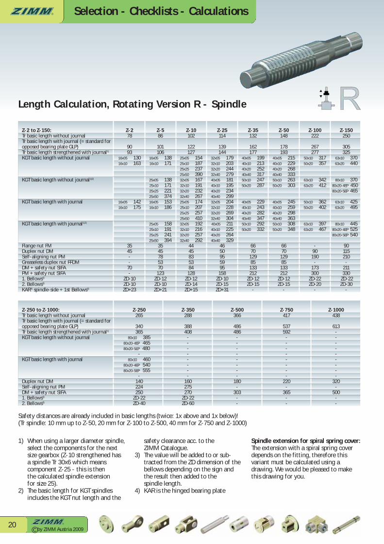
Length Calculation, Rotating Version R - Spindle
safety clearance acc. to the ZIMM Catalogue.
3) The value will be added to or sub-tracted from the ZD dimension of the bellows depending on the sign and the result then added to the spindle length.
4) KAR is the hinged bearing plate
1) When using a larger diameter spindle, select the components for the next size gearbox (Z-10 strengthened has a spindle Tr 30x6 which means component Z-25 - this is then the calculated spindle extension for size 25).
2) The basic length for KGT spindles includes the KGT nut length and the
Z-100222
267277
50x10 31750x20 357
63x10 34263x20 412
50x10 36250x20 402
63x10 39763x20 467
-90190
-173300
ZD-22ZD-20
-
Z-50148
178193
40x05 21540x10 22940x20 26840x40 33350x10 26350x20 303
40x05 24540x10 25940x20 29840x40 36350x10 30850x20 348
667012985133212
ZD-12ZD-15
-
Z-35132
162177
40x05 19940x10 21340x20 25240x40 31750x10 24750x20 287
40x05 22940x10 24340x20 28240x40 34750x10 29250x20 332
667012985133212
ZD-12ZD-15
-
Z-25114
139144
32x05 17932x10 20332x20 24432x40 27940x05 18140x10 19540x20 23440x40 29932x05 20432x10 22832x20 26932x40 30440x05 21140x10 22540x20 26440x40 329
4650955995158
ZD-10ZD-15ZD+31
Z-10102
122127
25x05 15425x10 18725x25 23725x50 39032x05 16732x10 19132x20 23232x40 26725x05 17425x10 20725x25 25725x50 41032x05 19232x10 21632x20 25732x40 292
4445835384128
ZD-12ZD-14ZD+15
Z-278
9093
16x05 13016x10 163
16x05 14216x10 175
3545--
70-
ZD-10ZD-10ZD+23
Z-586
101106
16x05 13816x10 171
25x05 13825x10 17125x25 22125x50 37416x05 15316x10 186
25x05 15825x10 19125x25 24125x50 394
3545785370123
ZD-12ZD-10ZD+21
Z-150250
305325
63x10 37063x20 440
80x10 37080x20-4EP 45080x20-5EP 465
63x10 42563x20 495
80x10 44580x20-4EP 52580x20-5EP 540
90115210-
211330
ZD-22ZD-30
-
Z-1000438
613---------
320-
500--
Z-750417
537592
--------
220-
365--
Z-500366
486486
--------
180-
303--
Z-350288
388408
--------
160275270
ZD-22ZD-60
Z-250265
340365
80x10 38580x20-4EP 46580x20-5EP 480
-80x10 460
80x20-4EP 54080x20-5EP 555
-140224250
ZD-22ZD-40
Z-2 to Z-150:Tr basic length without journalTr basic length with journal (= standard foropposed bearing plate GLP)Tr basic length strengthened with journal1)
KGT basic length without journal
KGT basic length without journal1)2)
KGT basic length with journal
KGT basic length with journal1)2)
Flange nut FMDuplex nut DMSelf-aligning nut PMGreaseless duplex nut FFDMDM + safety nut SIFAPM + safety nut SIFA1. Bellows3)
2. Bellows3)
KAR4) spindle-side + 1st Bellows3)
Z-250 to Z-1000:Tr basic length without journalTr basic length with journal (= standard foropposed bearing plate GLP)Tr basic length strengthened with journal1)
KGT basic length without journal
KGT basic length with journal
Duplex nut DMSelf-aligning nut PMDM + safety nut SIFA1. Bellows3)
2. Bellows3)
Spindle extension for spiral spring cover: The extension with a spiral spring coverdepends on the fitting, therefore thisvariant must be calculated using a drawing. We would be pleased to makethis drawing for you.
Safety distances are already included in basic lengths (twice: 1x above and 1x below)!(Tr spindle: 10 mm up to Z-50, 20 mm for Z-100 to Z-500, 40 mm for Z-750 and Z-1000)

Selection - Checklists - Calculations
© by ZIMM Austria 200921
Z-SeriesZIMM
Z
Size Version Ratio Thread versionSpindle Ø / pitch
Number ofthreads, material Stroke
List of system components
2
51025
3550100150
2503505007501000
SStandingversion
RRotatingversion
NNormale.g. i = 4:1
LLowe.g. i = 16:1
TrTrapezoid spindle(not specified = Tr)
Tr/SIFATr with safetynut SIFA
KGTBall screw drive
Tr18042004...
KGT16051610...
11-pitch(not specified= 1-pitch)2 *2-pitchIINOX (stainless steel)
LH *left-handed
H
StrokeH + strokein mm
List ofsystemcomponents(sequence notimportant)––> Section 7 -Catalogue 2008
*) Deliverable butnot stock item, delivery time on
request
Order example: Z - 10 - SN - Tr - 2004 - 1 - H 300 - FB390 - VS - BF
Size
Versi
on S
or R
Ratio
N o
r LTh
read
ver
sion
Spin
dle
diam
eter
Spin
dle
pitc
hNu
mbe
r of s
tart
s
Stro
ke
List o
fsy
stem
com
pone
nts
(sequ
ence
not
impo
rtan
t)
Z
+CONTROLWear control
Order Code