Seismic Performance Evaluation of Reinforced Plaster...
13
www.cafetinnova.org Indexed in Scopus Compendex and Geobase Elsevier, Chemical Abstract Services-USA, Geo-Ref Information Services-USA ISSN 0974-5904, Volume 05, No. 02 April 2012, P.P. 193-205 #02050201 Copyright © 2012 CAFET-INNOVA TECHNICAL SOCIETY. All rights reserved. Seismic Performance Evaluation of Reinforced Plaster Retrofitting Technique for Low-Rise Block Masonry Structures NAVEED AHMAD 1 , QAISAR ALI 2 , MOHAMMAD ASHRAF 3 , AKHTAR NAEEM 3 and BASHIR ALAM 3 1 ROSE School-IUSS Pavia, Pavia, Italy. 2 Earthquake Engineering Center, University of Engineering & Technology (UET), Peshawar, Pakistan. 3 Department of Civil Engineering, University of Engineering & Technology (UET), Peshawar, Pakistan. Email: [email protected] Abstract: Low-rise unreinforced block masonry structures are investigated for resistance against site amplified ground motions, before and after retrofitting with reinforced plaster. The aim of the study was to evaluate the effectiveness of indigenous and cost-effective retrofitting technique for improving the seismic performance of ordinary masonry structures. The retrofitting technique involved cement grouting of damaged walls and fixing steel wire mesh on wall surface, plastered with rich cement mortar. Experimental investigations carried out on block masonry material and prototype walls are analyzed to retrieve the mechanical characteristics for mathematical modeling of structures. Two case study low-rise (two storey) structures are assessed through nonlinear incremental dynamic time history analysis technique using natural accelerograms. The considered retrofitting technique increases the lateral load carrying capacity of in-plane walls by about 10 percent and ductility capacity by 100 percent and ensures flexure (toe crushing) response mechanism to lateral loading. The technique increased the seismic resistance of structures to ground shaking by 43 percent. It is observed that the retrofitted structures can survive ground shaking intensity up to 0.40g/0.50g whereas shaking intensity of 0.73g/0.90g (and above) may cause the structure collapse (with 95 percent confidence), indicating that the technique can be confidently used for improving the seismic performance of block masonry structures. Keywords: block masonry structures; reinforced plaster; ferrocement; cost-effective retrofitting, structure useful life. 1. Introduction: Significant proportion of building stock in urban areas are constructed using concrete block masonry in cement-mortar. For example, concrete blocks are used in construction of walls in the order of 10-20 percent in most of the Districts of Punjab and Sindh Provinces of Pakistan. In few other cases the percentage can reach event up to 40-60 percent e.g. District Karachi in Sindh and few other Districts in Northern areas of Khyber Pakhtoonkhwa of Pakistan (ERRA, 2006; Maqsood and Schwarz, 2008). Concrete block masonry is used mostly for one to two storey residential structures in urban areas. However, concrete block masonry walls are also used as an infill panel in reinforced concrete frame construction e.g. the City like Karachi (Badrashi et al., 2010) among others. Also, recently following major earthquake in Pakistan, the use of concrete block units has been increased for the re-construction activity in major affected areas (both urban and rural) due to the fact that concrete blocks can be easily and rapidly produced using even small machines (Stephenson, 2008). In the recent major earthquake Mw 7.6 2005 Kashmir, about 30 percent of the building stock subjected to ground shaking included block masonry structures in the nearby urban areas. Almost 60 percent of block masonry structures were either heavily damaged are collapsed (Naseer et al., 2010; Rossetto and Peiris, 2009), which is significant. The recent investigation on the seismic risk assessment of existing structures in Pakistan reported that regional block masonry structures subjected to ground shaking intensity of 0.30g can result in the collapse of 70 percent of the exposed building stock (Ahmad, 2011), which is due to the extremely low mechanical characteristics of existing block masonry material. This means that existing block masonry construction is at risk in the high hazard zones of the country e.g. Zone 3 (0.24g–0.32g) and Zone 4 (> 0.32g) as specified by BCP (2007), indicating that ordinary block masonry structures cannot be confidently constructed in high hazard zones. Similar, findings have been reported also by Mahmood and Ingham (2011) however observing also that significant amount of block masonry typologies are earthquake-prone even in moderate hazard zones e.g. Zone 2B (0.16–0.24g). This situation motivate research on the seismic vulnerability
Transcript of Seismic Performance Evaluation of Reinforced Plaster...
www.cafetinnova.org
Indexed in
Scopus Compendex and Geobase Elsevier, Chemical
Abstract Services-USA, Geo-Ref Information Services-USA
ISSN 0974-5904, Volume 05, No. 02
April 2012, P.P. 193-205
#02050201 Copyright © 2012 CAFET-INNOVA TECHNICAL SOCIETY. All rights reserved.
Seismic Performance Evaluation of Reinforced Plaster Retrofitting
Technique for Low-Rise Block Masonry Structures
NAVEED AHMAD1, QAISAR ALI
2, MOHAMMAD ASHRAF
3, AKHTAR NAEEM
3 and BASHIR ALAM
3
1ROSE School-IUSS Pavia, Pavia, Italy.
2Earthquake Engineering Center, University of Engineering & Technology (UET), Peshawar, Pakistan.
3Department of Civil Engineering, University of Engineering & Technology (UET), Peshawar, Pakistan.
Email: [email protected]
Abstract: Low-rise unreinforced block masonry structures are investigated for resistance against site amplified
ground motions, before and after retrofitting with reinforced plaster. The aim of the study was to evaluate the
effectiveness of indigenous and cost-effective retrofitting technique for improving the seismic performance of
ordinary masonry structures. The retrofitting technique involved cement grouting of damaged walls and fixing steel
wire mesh on wall surface, plastered with rich cement mortar. Experimental investigations carried out on block
masonry material and prototype walls are analyzed to retrieve the mechanical characteristics for mathematical
modeling of structures. Two case study low-rise (two storey) structures are assessed through nonlinear incremental
dynamic time history analysis technique using natural accelerograms. The considered retrofitting technique
increases the lateral load carrying capacity of in-plane walls by about 10 percent and ductility capacity by 100
percent and ensures flexure (toe crushing) response mechanism to lateral loading. The technique increased the
seismic resistance of structures to ground shaking by 43 percent. It is observed that the retrofitted structures can
survive ground shaking intensity up to 0.40g/0.50g whereas shaking intensity of 0.73g/0.90g (and above) may cause
the structure collapse (with 95 percent confidence), indicating that the technique can be confidently used for
improving the seismic performance of block masonry structures.
Keywords: block masonry structures; reinforced plaster; ferrocement; cost-effective retrofitting, structure useful
life.
1. Introduction:
Significant proportion of building stock in urban areas
are constructed using concrete block masonry in
cement-mortar. For example, concrete blocks are used
in construction of walls in the order of 10-20 percent in
most of the Districts of Punjab and Sindh Provinces of
Pakistan. In few other cases the percentage can reach
event up to 40-60 percent e.g. District Karachi in Sindh
and few other Districts in Northern areas of Khyber
Pakhtoonkhwa of Pakistan (ERRA, 2006; Maqsood and
Schwarz, 2008). Concrete block masonry is used mostly
for one to two storey residential structures in urban
areas. However, concrete block masonry walls are also
used as an infill panel in reinforced concrete frame
construction e.g. the City like Karachi (Badrashi et al.,
2010) among others. Also, recently following major
earthquake in Pakistan, the use of concrete block units
has been increased for the re-construction activity in
major affected areas (both urban and rural) due to the
fact that concrete blocks can be easily and rapidly
produced using even small machines (Stephenson,
2008).
In the recent major earthquake Mw 7.6 2005 Kashmir,
about 30 percent of the building stock subjected to
ground shaking included block masonry structures in
the nearby urban areas. Almost 60 percent of block
masonry structures were either heavily damaged are
collapsed (Naseer et al., 2010; Rossetto and Peiris,
2009), which is significant. The recent investigation on
the seismic risk assessment of existing structures in
Pakistan reported that regional block masonry structures
subjected to ground shaking intensity of 0.30g can result
in the collapse of 70 percent of the exposed building
stock (Ahmad, 2011), which is due to the extremely low
mechanical characteristics of existing block masonry
material. This means that existing block masonry
construction is at risk in the high hazard zones of the
country e.g. Zone 3 (0.24g–0.32g) and Zone 4 (> 0.32g)
as specified by BCP (2007), indicating that ordinary
block masonry structures cannot be confidently
constructed in high hazard zones. Similar, findings have
been reported also by Mahmood and Ingham (2011)
however observing also that significant amount of block
masonry typologies are earthquake-prone even in
moderate hazard zones e.g. Zone 2B (0.16–0.24g). This
situation motivate research on the seismic vulnerability
194 NAVEED AHMAD, QAISAR ALI, MOHAMMAD ASHRAF,
AKHTAR NAEEM and BASHIR ALAM
International Journal of Earth Sciences and Engineering
ISSN 0974-5904, Vol. 05, No. 02, April 2012, pp. 193-205
assessment of individual block masonry structures
toward disaster risk reduction (saving life during strong
ground motions) using efficient, yet affordable,
retrofitting techniques.
Cost-effective and efficient retrofitting techniques are
essential, particularly for the developing part of the
world exposed to moderate to strong ground motions.
Retrofitting techniques for masonry structures are
evolved to a much mature stage (ElGawady et al.,
2004), however its design and application may still be
affected by many factors like the structures typology
and its existing condition, performance objective, cost
of retrofitting, available time, resources and materials,
preservation of historical value etc., particularly in the
developing part of the world e.g. Pakistan, India, Iran,
among others which predominantly include masonry
structures. This clearly indicates the importance of
research on the investigation of efficient and cost-
effective retrofitting techniques for masonry structures.
The paper thus presents investigation carried out on
low-rise block masonry structures practiced mostly in
the urban areas of Pakistan, for the seismic resistance
evaluation of existing structures and their possible
improvement using indigenous and cost-effective
retrofitting technique. It included seismic performance
evaluation of structures; existing and retrofitted
(damaged structures) with reinforced plaster technique
developed and practiced at the Earthquake Engineering
Center of Peshawar. Experimental investigations carried
out recently at the Earthquake Engineering Center and
University of Engineering and Technology (UET)
Peshawar (Shoaib et al., 2011) on block masonry
assemblages and prototype walls (before and after
retrofitting) are considered for design and mathematical
modelling of case study structures.
Nonlinear dynamic time history analyses of four case
study structures are performed using natural
accelerograms, where the structures are assessed using
probabilistic approach taking into account the variability
of ground motions in performance evaluation. Ground
motions with different exceedance probability is
obtained for specified performance level of structures.
Example structures are investigated for the seismic
performance evaluation of the retrofitting technique
considering a single scenario earthquake and possible
events over the design life.
Masonry Walls Retrofitting Technique (Reinforced
Plaster):
The retrofitting technique investigated in the present
study included grout injection of cracks (for already
damaged walls) and application of steel welded wire
mesh on the surface of walls, plastered with rich
cement-sand mortar, the so called ferrocement overlay:
a thin layer of reinforced concrete consists of closely
spaced small size wire-mesh completely embedded in
cement mortar (ACI 549R-97, 1997). The technique
require relatively low level technical skills for
fabrication and application of ferrocement. The
provision of closely spaced steel wire-mesh in the
ferrocement overlay provides significant tensile strength
to retrofitted walls with low economic cost, without
adding significant additional mass to the structural
system, which makes the technique highly appealing in
developing part of the world exposed to significant
earthquakes.
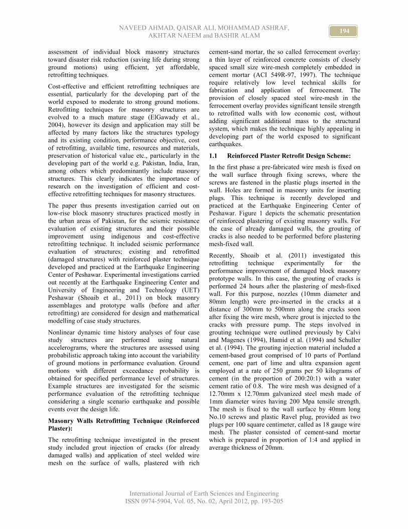
1.1 Reinforced Plaster Retrofit Design Scheme:
In the first phase a pre-fabricated wire mesh is fixed on
the wall surface through fixing screws, where the
screws are fastened in the plastic plugs inserted in the
wall. Holes are formed in masonry units for inserting
plugs. This technique is recently developed and
practiced at the Earthquake Engineering Center of
Peshawar. Figure 1 depicts the schematic presentation
of reinforced plastering of existing masonry walls. For
the case of already damaged walls, the grouting of
cracks is also needed to be performed before plastering
mesh-fixed wall.
Recently, Shoaib et al. (2011) investigated this
retrofitting technique experimentally for the
performance improvement of damaged block masonry
prototype walls. In this case, the grouting of cracks is
performed 24 hours after the plastering of mesh-fixed
wall. For this purpose, nozzles (10mm diameter and
80mm length) were pre-inserted in the cracks at a
distance of 300mm to 500mm along the cracks soon
after fixing the wire mesh, where grout is injected to the
cracks with pressure pump. The steps involved in
grouting technique were outlined previously by Calvi
and Magenes (1994), Hamid et al. (1994) and Schuller
et al. (1994). The grouting injection material included a
cement-based grout comprised of 10 parts of Portland
cement, one part of lime and ultra expansion agent
employed at a rate of 250 grams per 50 kilograms of
cement (in the proportion of 200:20:1) with a water
cement ratio of 0.8. The wire mesh was designed of a
12.70mm x 12.70mm galvanized steel mesh made of
1mm diameter wires having 200 Mpa tensile strength.
The mesh is fixed to the wall surface by 40mm long
No.10 screws and plastic Ravel plug, provided as two
plugs per 100 square centimeter, called as 18 gauge wire
mesh. The plaster consisted of cement-sand mortar
which is prepared in proportion of 1:4 and applied in
average thickness of 20mm.
195 Seismic Performance Evaluation of Reinforced Plaster Retrofitting Technique for
Low-Rise Block Masonry Structures
International Journal of Earth Sciences and Engineering
ISSN 0974-5904, Vol. 05, No. 02, April 2012, pp. 193-205
Figure 1: Schematic of Reinforced Plaster Retrofitting Technique for Existing Masonry Walls Developed and
Practiced at the Earthquake Engineering Center of Peshawar. From Left to Right and Top to Bottom: Required
Accessories, Drilling for Inserting Screw Plugs, Application and Fixing of Wire Mesh and Plastering of Wall
(Shahzada, 2006)
1.2 Observed Behavior of Block Masonry Walls
(Before and After Retrofitting):
This section is largely based on the experimental study
carried out by Shoaib et al. (2011) on block masonry
material and walls and the reinforced plaster retrofitting
technique recently developed and practiced by the
Earthquake Engineering Center of Peshawar. The
following sections briefly describe the testing program,
the mechanical characteristics of block masonry and in-
plane response of case study block masonry walls
(before and after retrofitting) important within the scope
of present research study.
1.2.1 Experimental Program:
The experimental investigation included in-plane quasi-
static cyclic test on six masonry walls: three sample
walls were representative of a short pier in single storey
structures (and first floor of double storey structures),
other three sample walls were representative of a ground
floor short pier in double storey structures. The piers
were first tested in the unreinforced state which were
retrofitted and tested again. The tested walls were
deformed into life safety performance range till the peak
load was developed, strength and stiffness degradation
is noticed and when repair to damage was feasible.
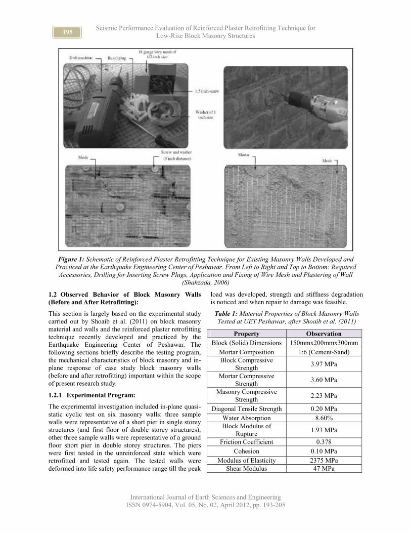
Table 1: Material Properties of Block Masonry Walls
Tested at UET Peshawar, after Shoaib et al. (2011)
Property Observation
Block (Solid) Dimensions 150mmx200mmx300mm
Mortar Composition 1:6 (Cement-Sand)
Block Compressive
Strength 3.97 MPa
Mortar Compressive
Strength 3.60 MPa
Masonry Compressive
Strength 2.23 MPa
Diagonal Tensile Strength 0.20 MPa
Water Absorption 8.60%
Block Modulus of
Rupture 1.93 MPa
Friction Coefficient 0.378
Cohesion 0.10 MPa
Modulus of Elasticity 2375 MPa
Shear Modulus 47 MPa
196 NAVEED AHMAD, QAISAR ALI, MOHAMMAD ASHRAF,
AKHTAR NAEEM and BASHIR ALAM
International Journal of Earth Sciences and Engineering
ISSN 0974-5904, Vol. 05, No. 02, April 2012, pp. 193-205
1.2.2 Basic Mechanical Properties of Block
Masonry:
It also included tests on masonry prism and masonry
panels, three samples for each, for the estimation of
compression, shear and diagonal tension strength,
Young and shear elastic moduli. Table 1 reports the
basic mechanical properties of block masonry
investigated in the present research study.
1.2.3 Observed Response of Walls (Before and
after Retrofitting):
All of the walls have shown a flexure response at the
initial stages whereby cracks where developed at the
base of the wall which propagated with increasing
lateral displacement till rocking of the wall is initiated.
However, inclined shear cracks were also developed
before pure rocking of wall may be achieved. Sliding is
also observed at the bed joints of wall. The final
damaged wall included severe inclined cracks in
masonry units and cracks at the head and bed joints. The
retrofitted walls developed flexure cracks at the base
which is propagated to ensure rocking of the wall.
Significant inclined cracks were observed at the
compressed toe of wall, which could finally lead to toe
crushing and possibly simultaneous overturning of the
wall.
Performance-Based Damage Scale:
For all the walls, the retrofitting technique changed the
response mechanism from a flexure-shear mixed type
response to a flexure-toe crushing type response, when
reinforced plaster was applied on both faces of the wall.
The mechanism is not changed when reinforced plaster
was applied on one face of the wall only. Shoaib et al.
(2011) reported the lateral force-displacement response
of tested walls (before and after retrofitting), where it
was observed that the retrofitting technique can increase
the lateral strength by ten percent and increases the
ductility (the ratio of ultimate displacement capacity to
yield displacement) by 100 percent due to ensuring
flexure response of walls. Increase in the idealized yield
displacement capacity of the retrofitted wall relative to
the counterpart unretrofitted wall was not significant.
In the present study, the following damage scale is
developed (after FEMA, 2003) in view of the trend
towards deformation-based seismic design and
assessment of block masonry structures (before ad after
retrofitting).
where θi represents the mean drift limit states i.e. drift
threshold value; θy represents the idealized yield drift
limit derived from the bi-linearization of lateral force-
displacement response of wall; θu represents the ultimate
drift limits. The indicated damage state and performance
levels are attained upon the exceedance of the specified
drift limit. The approximated observed θy is 0.11% for
unretrofitted wall and 0.13% for retrofitted wall while θu
is 0.62% for unretrofitted wall and 1.25% for retrofitted
wall.
2 Example Structures for Investigation:
2.1 General Characteristics of Block Masonry
Structures in Pakistan:
The block masonry construction in Pakistan consists of
load-bearing walls of 150mm to 200mm thickness,
using single block unit (block size 300mm length,
200mm width, 150mm thickness) i.e. single-leaf,
constructed in cement-sand mortar mix ratio of 1:6. The
blocks are generally manufactured from combination of
cement, sand, and crushed stone with a mix proportion
(by volume) of 1:6:12 to 1:8:14. This mix proportion
results in 80 to 100 block units for 50 kilograms of
cement (one bag) with significantly low compressive
strength (Naseer et al., 2010). However, the current
recommendations for reconstruction suggest block units
of compressive strength more than 10 MPa, which
cannot be achieved looking at the current practice in the
field.
These structures are provided with 130mm to 150mm
thick reinforced concrete slab, as also common for brick
masonry construction type in urban exposure. Light
wooden and steel roof truss with Galvanized Iron sheet
and wooden floors are also practiced now in rural and
urban parts of the country. The clear inter-story height
and ground floor height ranges roughly between 2.0m to
3.0m and 2.5m to 3.5m, respectively. The current
construction guidelines recommend the use of band
beams at plinth/ lintel/ roof levels in order to reduce the
aspect ratio of wall, avoid the out-of-plane bending of
walls and ensuring in-plane integrity of structures.
197 Seismic Performance Evaluation of Reinforced Plaster Retrofitting Technique for
Low-Rise Block Masonry Structures
International Journal of Earth Sciences and Engineering
ISSN 0974-5904, Vol. 05, No. 02, April 2012, pp. 193-205
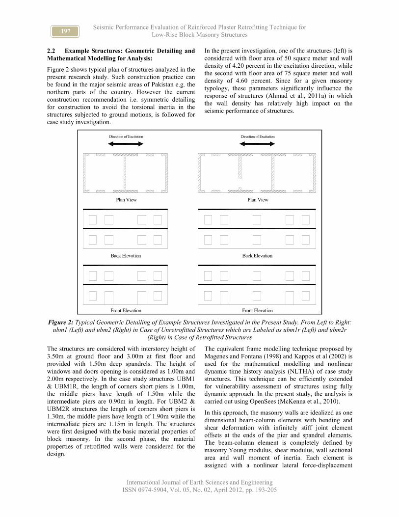
2.2 Example Structures: Geometric Detailing and
Mathematical Modelling for Analysis:
Figure 2 shows typical plan of structures analyzed in the
present research study. Such construction practice can
be found in the major seismic areas of Pakistan e.g. the
northern parts of the country. However the current
construction recommendation i.e. symmetric detailing
for construction to avoid the torsional inertia in the
structures subjected to ground motions, is followed for
case study investigation.
In the present investigation, one of the structures (left) is
considered with floor area of 50 square meter and wall
density of 4.20 percent in the excitation direction, while
the second with floor area of 75 square meter and wall
density of 4.60 percent. Since for a given masonry
typology, these parameters significantly influence the
response of structures (Ahmad et al., 2011a) in which
the wall density has relatively high impact on the
seismic performance of structures.
Direction of Excitation Direction of Excitation
Plan View
Back Elevation
Front Elevation
Plan View
Back Elevation
Front Elevation
Figure 2: Typical Geometric Detailing of Example Structures Investigated in the Present Study. From Left to Right:
ubm1 (Left) and ubm2 (Right) in Case of Unretrofitted Structures which are Labeled as ubm1r (Left) and ubm2r
(Right) in Case of Retrofitted Structures
The structures are considered with interstorey height of
3.50m at ground floor and 3.00m at first floor and
provided with 1.50m deep spandrels. The height of
windows and doors opening is considered as 1.00m and
2.00m respectively. In the case study structures UBM1
& UBM1R, the length of corners short piers is 1.00m,
the middle piers have length of 1.50m while the
intermediate piers are 0.90m in length. For UBM2 &
UBM2R structures the length of corners short piers is
1.30m, the middle piers have length of 1.90m while the
intermediate piers are 1.15m in length. The structures
were first designed with the basic material properties of
block masonry. In the second phase, the material
properties of retrofitted walls were considered for the
design.
The equivalent frame modelling technique proposed by
Magenes and Fontana (1998) and Kappos et al (2002) is
used for the mathematical modelling and nonlinear
dynamic time history analysis (NLTHA) of case study
structures. This technique can be efficiently extended
for vulnerability assessment of structures using fully
dynamic approach. In the present study, the analysis is
carried out using OpenSees (McKenna et al., 2010).
In this approach, the masonry walls are idealized as one
dimensional beam-column elements with bending and
shear deformation with infinitely stiff joint element
offsets at the ends of the pier and spandrel elements.
The beam-column element is completely defined by
masonry Young modulus, shear modulus, wall sectional
area and wall moment of inertia. Each element is
assigned with a nonlinear lateral force-displacement
198 NAVEED AHMAD, QAISAR ALI, MOHAMMAD ASHRAF,
AKHTAR NAEEM and BASHIR ALAM
International Journal of Earth Sciences and Engineering
ISSN 0974-5904, Vol. 05, No. 02, April 2012, pp. 193-205
constitutive law depending on the response mechanism
of wall. Considering the ultimate damage mechanisms
of masonry wall, after Calvi and Magenes (1997) and
Tomazevic (1999); the diagonal shear, flexure (toe
crushing), and shear sliding analytical models are
employed for lateral strength evaluation of a given wall:
where Vf represents the lateral strength for flexure (toe
crushing) mechanism; D represents the length of wall; t
represents the thickness of wall; p=P/(Dt) represents the
mean vertical stress due to axial load P; HP represents
the height of wall; ψ is 1.0 for a cantilever pier and 0.5
for a pier with fixed-fixed boundary conditions; fu
represents the compressive strength of masonry; k is a
coefficient used to idealize the stress distribution at the
compressed toe of wall (Magenes et al., 2000),
considered as 0.85; Vd represent the shear strength for
diagonal shear damage mechanism; ftu is the diagonal
tensile strength; b=1 for HP/D≤1, b=HP/D for
1<HP/D<1.5 and b=1.5 for 1.5≤HP/D; VS represents the
sliding shear strength; µ and c represent the coefficient
of friction and cohesion of masonry as global strength
parameters.
A correction factor is proposed (Magenes and Calvi,
1997; Mann and Muller, 1982) to transform the local
parameters obtained using triplet/couplet test to global
parameters. The above shear strength models have been
discussed earlier in Magenes and Calvi (1997) and
Tomazevic (1999) for appropriate applications.
Due to the provision of reinforced concrete slab, deep
spandrels, ring beam above the wall and band beam at
lintel level (in order to ensure strong-spandrel and
weak-pier condition), the response of spandrel is
approximately considered as elastic, whereas inelastic
response is considered only in the piers.
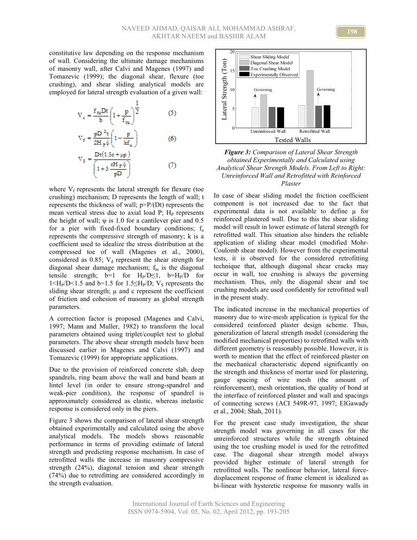
Figure 3 shows the comparison of lateral shear strength
obtained experimentally and calculated using the above
analytical models. The models shows reasonable
performance in terms of providing estimate of lateral
strength and predicting response mechanism. In case of
retrofitted walls the increase in masonry compressive
strength (24%), diagonal tension and shear strength
(74%) due to retrofitting are considered accordingly in
the strength evaluation.
Unreinforced Wall Retrofitted Wall0
5
10
15
20
Tested Walls
Lat
eral
Str
eng
th (
To
n)
Shear Sliding Model
Diagonal Shear Model
Toe Crushing Model
Experimentally Observed
GoverningGoverning
Figure 3: Comparison of Lateral Shear Strength
obtained Experimentally and Calculated using
Analytical Shear Strength Models. From Left to Right:
Unreinforced Wall and Retrofitted with Reinforced
Plaster
In case of shear sliding model the friction coefficient
component is not increased due to the fact that
experimental data is not available to define µ for
reinforced plastered wall. Due to this the shear sliding
model will result in lower estimate of lateral strength for
retrofitted wall. This situation also hinders the reliable
application of sliding shear model (modified Mohr-
Coulomb shear model). However from the experimental
tests, it is observed for the considered retrofitting
technique that, although diagonal shear cracks may
occur in wall, toe crushing is always the governing
mechanism. Thus, only the diagonal shear and toe
crushing models are used confidently for retrofitted wall
in the present study.
The indicated increase in the mechanical properties of
masonry due to wire-mesh application is typical for the
considered reinforced plaster design scheme. Thus,
generalization of lateral strength model (considering the
modified mechanical properties) to retrofitted walls with
different geometry is reasonably possible. However, it is
worth to mention that the effect of reinforced plaster on
the mechanical characteristic depend significantly on
the strength and thickness of mortar used for plastering,
gauge spacing of wire mesh (the amount of
reinforcement), mesh orientation, the quality of bond at
the interface of reinforced plaster and wall and spacings
of connecting screws (ACI 549R-97, 1997; ElGawady
et al., 2004; Shah, 2011).
For the present case study investigation, the shear
strength model was governing in all cases for the
unreinforced structures while the strength obtained
using the toe crushing model is used for the retrofitted
case. The diagonal shear strength model always
provided higher estimate of lateral strength for
retrofitted walls. The nonlinear behavior, lateral force-
displacement response of frame element is idealized as
bi-linear with hysteretic response for masonry walls in

199 Seismic Performance Evaluation of Reinforced Plaster Retrofitting Technique for
Low-Rise Block Masonry Structures
International Journal of Earth Sciences and Engineering
ISSN 0974-5904, Vol. 05, No. 02, April 2012, pp. 193-205
unretrofitted case, as recommended by Ahmad et al.
(2011b) for shear mechanism of masonry walls. Similar,
constitutive law is also used recently by Menon and
Magenes (2011) for seismic analysis of masonry
structures. The retrofitted walls showed flexure
response with toe damage for which bi-linear rocking
re-centering rule is approximately used. Figure 4 shows
typical force-displacement rule for shear and flexure
mechanism of masonry walls which are employed for
unretrofitted and retrofitted cases, respectively, in the
present study.
Figure 4: Force-Displacement Constitutive Law for In-
Plane Lateral Response of Walls, after Ahmad (2011b):
From Left to Right: Force-Displacement Idealization
for Shear Mechanism (Approximately Extended to
Unretrofitted Walls) and Force-Displacement
Idealization for Flexure Mechanism (Approximately
Extended to Retrofitted Walls)
3 Performance Evaluation of Block Masonry
Structures:
3.1 Nonlinear Dynamic Reliability Based Seismic
Assessment Method (NDRM):
The study included a nonlinear dynamic reliability
based approach for probabilistic-based seismic
performance assessment of case study structures. This
includes the incremental dynamic analysis (IDA)
technique for structural analysis as proposed by
Vamvatsikos and Cornell (2002), to obtain demand
(drift demand) on a structure in a probabilistic fashion
which is convolve with the probabilistic capacity (drift
capacity) to obtain the exceedance probability of
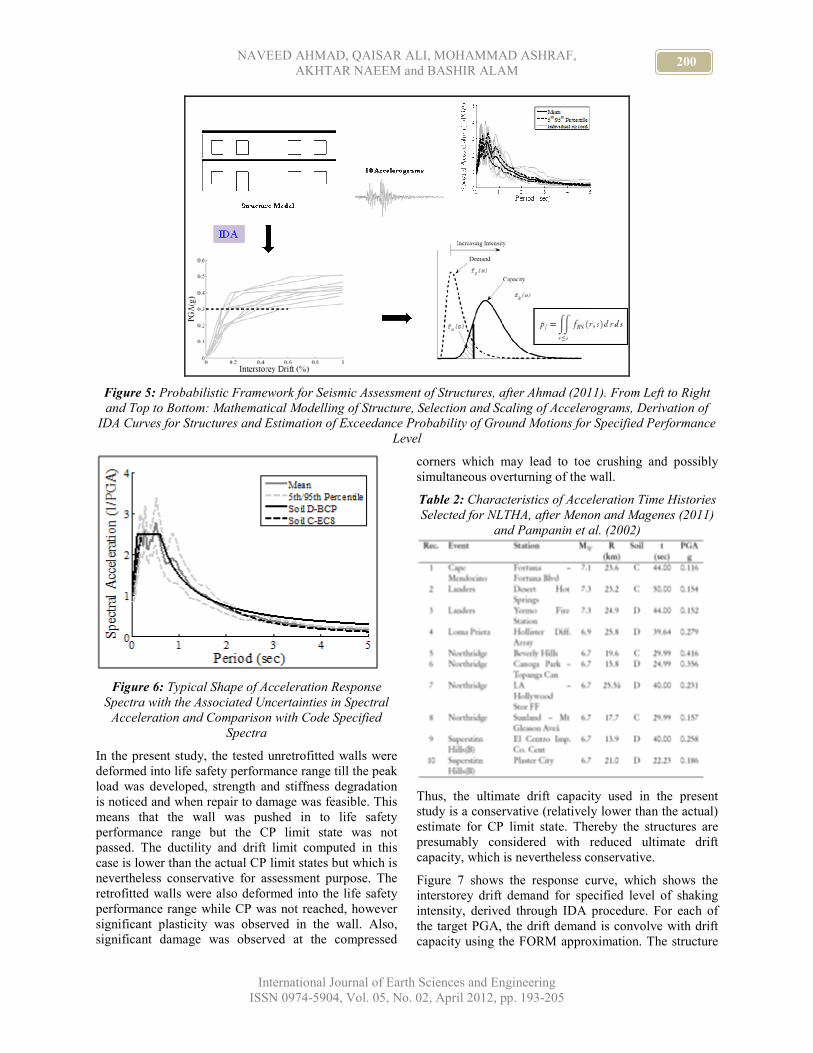
specified damage state (e.g. collapse). Figure 5
describes graphically the probabilistic-based assessment
framework.
Generally, the exceedance probability of specified
damage state for a given ground motion is obtained
using the classical reliability formulation that includes
the integration of joint probability density function of
demand and capacity, which is nevertheless
inconvenient to evaluate numerically. The present study
thus employed the First Order Reliability Method
FORM approximations (Der Kiureghian, 2005; Pinto et
al., 2004) to obtain the damage state exceedance
probability. This procedure has been recently
investigated against moderate and large magnitude
earthquakes for damage and collapse assessment of
existing structures in Pakistan (Ahmad, 2011) which
shows reasonable performance of the approach.
The case study structures are analyzed dynamically
using NLTHA with ten natural accelerograms extracted
from the PEER NGA data base for stiff soil site and
inter-mediate field condition i.e. sites within 15km to
30km of fault rupture (see Figure 6 and Table 2).
The selected accelerograms are compatible with the
Pakistan building code (BCP, 2007) specified
acceleration response spectrum for Type D soil and EC8
(CEN, 2004) specified response spectrum for Type C
soil of NEHRP classification. The accelerograms are
linearly scaled to multiple levels of shaking intensity in
order to derive response curve (drift demand correlated
with shaking intensity) for a given structure which are
employed to calculate the probability of exceedance of
specified limit state given the shaking intensity.
3.2 Collapse Assessment of Case Study Structures:
In the present study the collapse limit state corresponds
to the damage level when structure is forced to near-
collapse or complete collapse state. This damage level
occurs when collapse prevention (CP) is exceeded as
specified for the performance-based assessment and
design of structures. The physical damage corresponds
to the state of structure on the verge of partial and total
collapse where the occupants may be injured and
structural damages are not economically repairable.
200 NAVEED AHMAD, QAISAR ALI, MOHAMMAD ASHRAF,
AKHTAR NAEEM and BASHIR ALAM
International Journal of Earth Sciences and Engineering
ISSN 0974-5904, Vol. 05, No. 02, April 2012, pp. 193-205
Figure 5: Probabilistic Framework for Seismic Assessment of Structures, after Ahmad (2011). From Left to Right
and Top to Bottom: Mathematical Modelling of Structure, Selection and Scaling of Accelerograms, Derivation of
IDA Curves for Structures and Estimation of Exceedance Probability of Ground Motions for Specified Performance
Level
Figure 6: Typical Shape of Acceleration Response
Spectra with the Associated Uncertainties in Spectral
Acceleration and Comparison with Code Specified
Spectra
In the present study, the tested unretrofitted walls were
deformed into life safety performance range till the peak
load was developed, strength and stiffness degradation
is noticed and when repair to damage was feasible. This
means that the wall was pushed in to life safety
performance range but the CP limit state was not
passed. The ductility and drift limit computed in this
case is lower than the actual CP limit states but which is
nevertheless conservative for assessment purpose. The
retrofitted walls were also deformed into the life safety
performance range while CP was not reached, however
significant plasticity was observed in the wall. Also,
significant damage was observed at the compressed
corners which may lead to toe crushing and possibly
simultaneous overturning of the wall.
Table 2: Characteristics of Acceleration Time Histories
Selected for NLTHA, after Menon and Magenes (2011)
and Pampanin et al. (2002)
Thus, the ultimate drift capacity used in the present
study is a conservative (relatively lower than the actual)
estimate for CP limit state. Thereby the structures are
presumably considered with reduced ultimate drift
capacity, which is nevertheless conservative.
Figure 7 shows the response curve, which shows the
interstorey drift demand for specified level of shaking
intensity, derived through IDA procedure. For each of
the target PGA, the drift demand is convolve with drift
capacity using the FORM approximation. The structure
201 Seismic Performance Evaluation of Reinforced Plaster Retrofitting Technique for
Low-Rise Block Masonry Structures
International Journal of Earth Sciences and Engineering
ISSN 0974-5904, Vol. 05, No. 02, April 2012, pp. 193-205
reliability against the collapse is calculated (shown in
Figure 8) which can provide help on identifying the
critical ground motions with different confidence level.
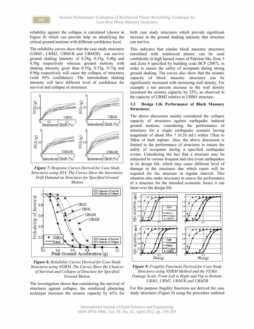
The reliability curves show that the case study structures
(UBM1, UBM2, UBM1R and UBM2R) can survive
ground shaking intensity of 0.28g, 0.35g, 0.40g and
0.50g respectively whereas ground motions with
shaking intensity great than 0.55g, 0.73g, 0.73g and
0.90g respectively will cause the collapse of structures
(with 95% confidence). The intermediate shaking
intensity will have different level of confidence for
survival and collapse of structures.
Figure 7: Response Curves Derived for Case Study
Structures using IDA. The Curves Show the Interstorey
Drift Demand on Structures for Specified Ground
Motion
Figure 8: Reliability Curves Derived for Case Study
Structures using NDRM. The Curves Show the Chances
of Survival and Collapse of Structure for Specified
Ground Motion
The investigation shows that considering the survival of
structures against collapse, the reinforced plastering
technique increases the seismic capacity by 43% for
both case study structures which provide significant
increase in the ground shaking intensity that structure
can survive.
This indicates that similar block masonry structures
retrofitted with reinforced plaster can be used
confidently in high hazard zones of Pakistan like Zone 3
and Zone 4 specified by building code BCP (2007), in
order to ensure the safety of occupants during strong
ground shaking. The curves also show that the seismic
capacity of block masonry structures can be
significantly increased with increasing wall density. For
example a ten percent increase in the wall density
increased the seismic capacity by 25%, as observed in
the capacity of UBM2 relative to UBM1 structure.
3.3 Design Life Performance of Block Masonry
Structures:
The above discussion mainly considered the collapse
capacity of structures against earthquake induced
ground motions, considering the performance of
structures for a single earthquake scenario having
magnitude of about Mw 7 (0.26 std.) within 15km to
30km of fault rupture. Also, the above discussion is
limited to the performance of structures to ensure the
safety of occupants during a specified earthquake
events. Considering the fact that a structure may be
subjected to various frequent and rare event earthquakes
in its design life, which may cause different level of
damage in the structures due which repair will be
required for the structure at regular interval. This
situation also make necessary to assess the performance
of a structure for the intended economic losses it can
incur over the design life.
Figure 9: Fragility Functions Derived for Case Study
Structures using NDRM Method and the FEMA
Damage Scale. From Left to Right and Top to Bottom:
UBM1, UBM2, UBM1R and UBM2R
For this purpose fragility functions are derived for case
study structures (Figure 9) using the procedure outlined

202 NAVEED AHMAD, QAISAR ALI, MOHAMMAD ASHRAF,
AKHTAR NAEEM and BASHIR ALAM
International Journal of Earth Sciences and Engineering
ISSN 0974-5904, Vol. 05, No. 02, April 2012, pp. 193-205
in Ahmad (2011). Vulnerability curves are derived
convolving the structure fragility functions with the
economic consequence factor (ECF), where ECF relates
physical damage with the monetary loss for the required
repair as a fraction of total replacement cost of structure.
The damage scale, as developed earlier, and ECF
proposed by FEMA (2003) is used in the present study.
This damage scale requires the CP and Yield limit state
drift capacities to develop the whole damage scale, see
Eq. (1) to (4). The FEMA ECF specify repair cost ratio
of 0.02 for slight damage, 0.10 for moderate damage,
0.50 for heavy damage and 1.0 for near-
collapse/collapse structures.
0 0.5 1 1.50
0.2
0.4
0.6
0.8
1
Peak Ground Acceleration(g)
MD
R
Mea
n D
amag
e R
atio
UBM2
UBM1R
UBM2R
UBM1
Figure 10: Vulnerability Curves Derived for Case Study
Structures using FEMA Economic Consequence Factor.
The Curves Show the Ratio of the Cost of Repair to
Replacement (i.e. MDR) of Structure for Specified
Ground Motion
For the case study applications, the structures are
investigated in the northern parts of Pakistan where such
construction system is practiced abundantly, as
mentioned earlier. The District of Mansehra is
considered for application in the present study, which
also presents area with high seismic hazard.
0.01 0.1 10.00001
0.0001
0.001
0.01
0.1
1
10
Peak Ground Acceleration(g)
Annual
Pro
bab
ilit
y o
f E
xce
edan
ce
PMD Seismicity Model
GSHAP Seismicity Model
Figure 11: Seismic Hazard Curves Derived for
Mansehra District through PSHA using the PMD and
GSHAP Seismicity Models
The scope of this case study is to assess the block
masonry performance subjected to different possible
earthquakes in the region. The probabilistic framework
as outlined by Ahmad (2011) is used to assess structures
for the derivation of average annual loss (AAL). The
AAL represents the annual amount needed to be
arranged every year in order to be ready for the required
repair following any earthquake event in the region over
the design life of structure.
For this purpose all possible seismic sources around the
region is considered, for which possible ground motions
are generated using empirical ground motion prediction
equations. The ground motions are assigned with the
associated annual probability in order to derive the
hazard curve using the standard PSHA framework (see
Figure 11). In the present study three ground motion
prediction equations (Abrahamson and Silva, 2008;
Boore and Atkinson, 2008; Campbell and Bozorgnia,
2008) and two seismicity models (GSHAP after
Giardini et al., 1999; and PMD, 2007) are used to derive
hazard curve. The vulnerability and hazard curves are
convolved to estimate the AAL. Figure 12 shows the
AAL calculated for each of the case study structures.
UBM1 UBM2 UBM1R UBM2R0
0.5
1
1.5
2
Structure
Av
erag
e A
nn
ual
Lo
ss
Per
cen
tag
e o
f R
epla
cem
ent
Co
st
0.38
0.67
0.97
1.60
Figure 12: Average Annual Economic Losses (AAL)
Calculated for Case Study Structures in Mansehra
District. The AAL Specify the Amount (as a Fraction of
Replacement Cost) Required on Annual Bases for the
Regular Repair and Maintenance of Structures due to
Earthquakes
It is observed that UBM1, UBM2, UBM1R and
UBM2R structure will acquire AAL of 1.60, 0.97, 0.67
and 0.38 percent of the replacement cost of structure
respectively, resulting in 63, 103, 150 and 263 years of
useful life of structures. This indicates that the
retrofitting technique will reduce the economic losses of
both case study structures by 60 percent on annual bases
and will increase the useful life of structure by about
150 percent. The useful life of structure here represents
the time span when the structure accumulated economic
losses reaches the replacement cost.
203 Seismic Performance Evaluation of Reinforced Plaster Retrofitting Technique for
Low-Rise Block Masonry Structures
International Journal of Earth Sciences and Engineering
ISSN 0974-5904, Vol. 05, No. 02, April 2012, pp. 193-205
4 Closure:
4.1 Summary:
The aim of the study was to evaluate the performance of
block masonry structures before and after retrofitted
with reinforced plaster in order to assess the feasibility
of cost-effective and indigenous retrofitting technique
for improving the seismic performance of masonry
structures. Investigation is carried on block masonry
construction system against earthquake induced site
amplified ground motions. It included incremental
dynamic analysis of example structures for the
derivation of seismic response curves which are
analyzed through FORM approximation in order to
derive the structure reliability curves. Furthermore,
fragility functions are also derived which are employed
to derive the vulnerability curves. Additionally, PSHA
is carried out to develop seismic hazard curves for
Mansehra District (a high seismicity region). The
economic loss the structure can incur on annual bases is
calculated convolving the site hazard with the structure
vulnerability curves. This also gave, inversely, the
useful life of unretrofitted and retrofitted structures. The
investigation showed significant good performance of
the reinforced plastering technique in improving the
capacity of block masonry structures against earthquake
induced shaking.
4.2 Conclusions:
The following conclusions are derived based on the
seismic analysis of block masonry structures that can
ensure in-plane lateral response to ground shaking (right
through the length of walls). The out-of-plane failure of
walls in these structures are avoided practicing
restricted wall aspect ratio (height-to-thickness ratio)
and ensuring good wall-to-wall and wall-to-floor
connectivity. The case study structures are considered
with rigid reinforced concrete floors provided with ring
beam (monolithically connecting walls to the floor),
band beam (at the lintel level) and deep spandrels
(ensuring strong-spandrel to weak-pier condition). The
in-plane walls are considered with inelastic response
while the spandrels are considered with elastic response.
The study considered the experimentally obtained
mechanical properties of block masonry in Pakistan. In
the case study structures, the lateral strength of
unreinforced wall is provided by shear damage
mechanism (sliding shear model, modified Mohr-
Coulomb strength model) while the counterpart
retrofitted wall provided lateral strength with flexure
(toe crushing) mechanism. The lateral strength of
retrofitted wall increased by ten percent while the
ductility and drift capacity increased by about 100
percent. These findings are also applicable to block
masonry structure of the above characteristics and the
reinforced plaster design scheme as mentioned.
• For both unretrofitted and retrofitted walls, the
analytical lateral shear strength models are comparable
in predicting the response mechanism of walls
investigated though in-plane quasi-static cyclic test. The
models (Mohr-Coulomb shear model in case of
unretrofitted wall and toe crushing model in case of
retrofitted wall) provided reasonable estimate of lateral
shear strength.
• The investigation on case study structures showed
that considering the survival of structures against
collapse, the technique increases the seismic capacity by
43% which can provide significant increase in the
ground shaking intensity the structure can survive (with
95% confident).
• Locating and investigating the structures in high
seismicity area showed that the technique will reduce
the economic losses by about 60 percent on annual
bases and will increase the useful life of structure by
about 150 percent.
• The example unreinforced block masonry structures
retrofitted with reinforced plaster can ensure the safety
of occupants during strong ground motion, thus can be
confidently used in moderate to high hazard zones, as
mentioned.
• The better seismic performance of case study
retrofitted structures is primarily governed by the
increase in ductility capacity of walls while less
contribution (almost negligible) is provided by ten
percent increase in lateral strength.
• Additionally, the investigation also showed that a
ten percent increase in the wall density increases the
seismic capacity by 25 percent, reducing the economic
losses by 40 percent and increasing the structure useful
life by 63 percent. This indicates that the wall density of
masonry structures is also a crucial parameter in
improving the seismic performance.
4.3 Future Developments:
• There is a need to further investigate the reinforced
plaster retrofitting technique for masonry walls of
different geometry and loading condition. It can help in
developing generalized lateral shear strength models
which can be employed then confidently to assess the
performance of retrofitted structures analytically.
• The present study investigated masonry structures
with toe crushing mechanism of retrofitted walls and
ductility 100 percent greater than the counterpart
unretrofitted case. Further investigated is required to
understand the response mechanism and ductility
capacity for various cases of walls varying the
geometric and loading conditions to generalize the
effect of reinforced plaster for structures with any
geometric detailing.
• There is a need to further investigate retrofitted
walls with various geometries and reinforced plaster
204 NAVEED AHMAD, QAISAR ALI, MOHAMMAD ASHRAF,
AKHTAR NAEEM and BASHIR ALAM
International Journal of Earth Sciences and Engineering
ISSN 0974-5904, Vol. 05, No. 02, April 2012, pp. 193-205
design schemes to deduce deformation-related
performance objectives, defining different level of
required repair with the associated cost of repair, in
retrofitting techniques in view of the trend towards
deformation-based seismic design of structures.
• The present case study investigation considered bi-
linear hysteretic rule for shear damage mechanism
(unretrofitted case) and bi-linear centering rule for toe
crushing mechanism (retrofitted case). However,
investigation is required in this regard which may
further improve the findings reported herein and which
can in turn increase the confidence of approach in future
applications.
Acknowledgement:
The authors are grateful to Prof. Jason Ingham of the
University of Auckland, New Zealand; Prof. Joanna M.
Dulinska of the University of Cracow, Poland and Asst.
Prof. Paloma Pineda of the University of Seville, Spain
for their efforts in reading the manuscript in detail,
kindly encouraging the research study and providing us
with constructive comments and remarks which were
very helpful in improving the manuscript.
References:
[1] Abrahamson, N. and Silva, W. (2008), Summary of
the Abrahamson and Silva NGA ground--motion
relations, Earthquake Spectra, 24(1); 67-97.
[2] ACI 549R-97. (1997). State-of-the-art report on
ferrocement. ACI Committee Report/ACI 549R-97,
American Concrete Institute (ACI), Detroit, USA.
(http://www.bpesol.com/bachphuong/media/images
/book/549r_97.pdf)
[3] ADB-WB. (2005). Pakistan 2005 earthquake:
Preliminary damage and needs assessment.
Technical Document, Asian Development Bank
and World Bank, Islamabad, Pakistan.
(http://www.adb.org/Documents/Reports/pakistan-
damage-needs-assessment.pdf)
[4] Ahmad, N. (2011). Seismic risk assessment and
loss estimation of building stock of Pakistan. PhD
Thesis, ROSE School-IUSS Pavia, Pavia, Italy.
[5] Ahmad, N., Ali, Q., Ashraf, M., Naeem, K. and
Alam, B. (2011a). Seismic structural design codes
evolution in Pakistan and critical investigation of
masonry structures for seismic design
recommendations. International Journal of Civil,
Structural, Environmental and Infrastructure
Engineering Research and Development; 1(1): 42-
85. (http://www.epernicus.com/shared_documents
/1139/ijcerd-civil-engg-Seismic_Structural_
Design_ Codes_Evolution_-Naveed-Ahmad.pdf)
[6] Ahmad, N., Crowley, H., Pinho, R. and Ali, Q.
(2011b). Frame-elements constitutive law for
nonlinear static and dynamic analyses of masonry
buildings. In Cheung, S. O., Yazdani, F., Ghafoori,
N. and Singh A. (eds.): Modern Methods and
Advances in Structural Engineering and
Construction; Research Publishing Service,
Singapore. (http://rpsonline.com.sg/proceedings/
9789810879204/html/978-981-08-7920-4_S2-
S63.xml)
[7] Badrashi, Y., Ali, Q. and Ashraf, M. (2010).
Reinforced concrete buildings in Pakistan. EERI
Housing Report, World Housing Encyclopedia,
Oakland, CA, USA. (http://www.world-
housing.net/WHEReports/wh100184.pdf)
[8] BCP-2007. (2007). Building Code of Pakistan–
Seismic provision 2007. Technical Document,
Ministry of Housing and Works, Islamabad,
Pakistan. (http://www.pec.org.pk/downloadables/
buildingCode/Building Code of Pakistan.zip)
[9] Boore, D.M. and Atkinson, G.M. (2008), Ground–
motion prediction equations for the average
horizontal component of PGA, PGV, and 5%–
damped PSA at spectral periods between 0.01s and
10.0s. Earthquake Spectra, 24(1); 99-138.
[10] Calvi, G.M. and Magenes, G. (1994). Experimental
results on unreinforced masonry shear walls
damaged and repaired, Proceedings of Tenth
International Brick and Block Masonry Conference,
Calgary, Canada.
[11] Campbell, K. and Bozorgnia, Y. (2008), NGA
ground motion model for the geometric mean
horizontal component of PGA, PGV, PGD and 5%
damped linear elastic response spectra for periods
ranging from 0.01 to 10s. Earthquake Spectra;
24(1): 139-171.
[12] CEN, (2004). Eurocode 8: Design of structures for
earthquake resistance, Part1: General rules-seismic
actions and general requirements for buildings, EN
1998-1-3, CEN, Brussels, Belgium.
[13] Der Kiureghian, A. (2005). First– and second–order
reliability methods. In Nikolaidis, E., Ghiocel, D.
M. and Singhal, S. (eds.) Engineering design
reliability handbook.
[14] ElGawady, M., Lestuzzi, P. and Badoux, M.
(2004). A review of conventional seismic
retrofitting techniques for URM. Proceedings of the
Thirteenth International Brick and Block Masonry
Conference, Amsterdam. (http://imacwww.epfl.ch/
GenieParasismique/EDOC_ST09/Course_6/old/89
ElGA%2013-IBMaC%20state%20of%20the
%20art.pdf)
[15] ERRA. (2006). Earthquake reconstruction and
rehabilitation in earthquake affected areas.
Earthquake Reconstruction and Rehabilitation
Authority (ERRA), Islamabad, Pakistan.
[16] FEMA. (2003). Multi–hazard loss estimation
methodology, earthquake model. HAZUS-MH
Technical Manual, Federal Emergency
205 Seismic Performance Evaluation of Reinforced Plaster Retrofitting Technique for
Low-Rise Block Masonry Structures
International Journal of Earth Sciences and Engineering
ISSN 0974-5904, Vol. 05, No. 02, April 2012, pp. 193-205
Management Agency (FEMA), Washington, DC,
USA.
[17] Giardini, D., Grunthal, G., Shedlock, K.M., and
Zhang, P. (1999), The GSHAP: global seismic
hazard map. Annali Di Geofisica, 42(6), 1225-
1230.
[18] Hamid, A., Mahmoud, A. and Abo El Maged, S.
(1994). Strengthening and repair of unreinforced
masonry structures: state-of-the-art. Proceedings of
Tenth International Brick and Block Masonry
Conference, Calgary, Canada.
[19] Magenes, G. and Calvi, G.M. (1997). In-plane
seismic response of brick masonry walls,
Earthquake Engineering and Structural Dynamics,
26 (11), 1091-1112.
[20] Magenes, G. and Fontana, D. (1998). Simplified
non-linear seismic analysis of masonry buildings.
Proceedings of the British Masonry Society, 5(8),
190-195.
[21] Magenes, G., Bolognini, D. and Braggio, C. (2000).
Metodi semplificati per l’analisi sismica non lineare
di edifici in muratura (in Italian), GNDT, Rome,
Italy.
[22] Mahmood, H. and Ingham, J.M. (2011). Seismic
vulnerability assessment of Pakistan unreinforced
masonry buildings at a national scale.
Seismological Research Letters; 82(5), 676-685.
[23] Mann, W. and Muller, H. (1982). Failure of shear-
stressed masonry-an enlarged theory, tests, and
application to shear walls. Proceedings of the
British Ceramic Society 27, 223-235.
[24] Maqsood, S.T. and Schwarz, J. (2008). Seismic
vulnerability of existing building stock in Pakistan.
Proceedings of the Fourteenth World Conference
on Earthquake Engineering. Beijing, China.
[25] McKenna, F., Fenves, G.L. and Scott, M.H. (2010).
Open system for earthquake engineering simulation
(OpenSees) version2.1.1, University of California,
Berkeley, CA, USA. (http://opensees.berkeley.edu)
[26] Menon, A. and Magenes, G. (2011). Definition of
seismic input for out-of-plane response of masonry
walls: I. parametric study. Journal of Earthquake
Engineering; 15(2), 165-194.
[27] Naseer, A., Naeem, A., Hussain, Z. and Ali, Q.
(2010). Observed seismic behavior of buildings in
northern Pakistan during the 2005 Kashmir
earthquake. Earthquake Spectra; 26(2): 425-449.
[28] Pampanin, S., Christopoulos, C., and Priestley, M.
J. N. (2002). Residual deformations in the
performance-based seismic assessment of frame
structures. Technical Report, IUSS Press, Pavia,
Italy.
[29] Pinto, P.E., Giannini, R., and Franchin, P. (2004).
Seismic reliability analysis of structures. IUSS
Press, Pavia, Italy.
[30] PMD. (2007), Seismic hazard analysis and zonation
for Pakistan, Azad Jammu and Kashmir. Technical
Report, Pakistan Meteorological Department
(PMD), Islamabad, Pakistan.
[31] Rossetto, T. and Peiris, N. (2009). Observations of
damage due to the Kashmir earthquake of October
8, 2005 and study of current seismic provisions for
buildings in Pakistan. Bulletin of Earthquake
Engineering; 7(3):681-699.
[32] Schuller, M., Atkinson, R. and Borgsmiller, J.
(1994). Injection grouting for repair and retrofit of
unreinforced masonry. Proceedings of Tenth
International Brick and Block Masonry Conference,
Calgary, Canada.
[33] Shahzada, K. (2006). Field practicing manual:
Guidelines for standard construction (English
Translation). Technical Document, Earthquake
Engineering Center, Peshawar, Pakistan.
(http://iisee.kenken.go.jp/net/seismic_design_code/
pakistan/field_practicing_manual.pdf)
[34] Shah, A.A. (2011). Applications of ferrocement in
strengthening of unreinforced masonry columns.
International Journal of Geology; 5(1), 21-27.
(http://www.naun.org/journals/geology/20-080.pdf)
[35] Shoaib, M., Naseer, A., Shahzada, K., Naeem, A.
and Ashraf, M. (2011). Earthquake disaster
mitigation through retrofitting of unreinforced
concrete block masonry buildings. Advanced
Material Research; 255-260,2627-2631.
[36] Stephenson, M. (2008). Notes from experience in
post-earthquake rural housing reconstruction in
Pakistan. Proceedings of the Workshop on Build
Back Better, Beijing, China. (http://www.un.org.cn/
public/resource/9330387be56a506bac9cae9aef6d54
00.pdf)
[37] Tomazevic, M. (1999). Earthquake-resistant design
of masonry buildings-innovation in structures and
construction Vol.1, Imperial College Press,
London, UK.
[38] Vamvatsikos, D. and Cornell, C. (2002).
Incremental dynamic analysis. Earthquake
Engineering and Structural Dynamics, 31(3), 491-
514.
[39] Kappos, A.J., Penelis, G.G. and Drakopoulos, C.G.
(2002). “Evaluation of simplified models for lateral
load analysis of unreinforced masonry buildings”,
Journal of Structural Engineering, 128(7), 890-897.