
Seismic evidence of gas hydrates, multiple BSRs and fluid ...
30
HAL Id: hal-01539107 https://hal.archives-ouvertes.fr/hal-01539107 Submitted on 14 Jun 2017 HAL is a multi-disciplinary open access archive for the deposit and dissemination of sci- entific research documents, whether they are pub- lished or not. The documents may come from teaching and research institutions in France or abroad, or from public or private research centers. L’archive ouverte pluridisciplinaire HAL, est destinée au dépôt et à la diffusion de documents scientifiques de niveau recherche, publiés ou non, émanant des établissements d’enseignement et de recherche français ou étrangers, des laboratoires publics ou privés. Seismic evidence of gas hydrates, multiple BSRs and fluid flow offshore Tumbes Basin, Peru Constance Auguy, Gérôme Calvès, Ysabel Calderon, Stéphane Brusset To cite this version: Constance Auguy, Gérôme Calvès, Ysabel Calderon, Stéphane Brusset. Seismic evidence of gas hy- drates, multiple BSRs and fluid flow offshore Tumbes Basin, Peru. Marine Geophysical Research, Springer Verlag, 2017, 10, pp.339-339. 10.1007/s11001-017-9319-2. hal-01539107
Transcript of Seismic evidence of gas hydrates, multiple BSRs and fluid ...
HAL Id: hal-01539107https://hal.archives-ouvertes.fr/hal-01539107
Submitted on 14 Jun 2017
HAL is a multi-disciplinary open accessarchive for the deposit and dissemination of sci-entific research documents, whether they are pub-lished or not. The documents may come fromteaching and research institutions in France orabroad, or from public or private research centers.
L’archive ouverte pluridisciplinaire HAL, estdestinée au dépôt et à la diffusion de documentsscientifiques de niveau recherche, publiés ou non,émanant des établissements d’enseignement et derecherche français ou étrangers, des laboratoirespublics ou privés.
Seismic evidence of gas hydrates, multiple BSRs andfluid flow offshore Tumbes Basin, Peru
Constance Auguy, Gérôme Calvès, Ysabel Calderon, Stéphane Brusset
To cite this version:Constance Auguy, Gérôme Calvès, Ysabel Calderon, Stéphane Brusset. Seismic evidence of gas hy-drates, multiple BSRs and fluid flow offshore Tumbes Basin, Peru. Marine Geophysical Research,Springer Verlag, 2017, 10, pp.339-339. �10.1007/s11001-017-9319-2�. �hal-01539107�

Multiple BSRs and fluid flow offshore Tumbes Basin, Peru. R1
1
Seismic evidence of gas hydrates, multiple BSRs and fluid 1
flow offshore Tumbes Basin – Peru. 2
Constance Auguy 1, Gérôme Calvès 1*, Ysabel Calderon 1,2, Stéphane Brusset 1 3
1 Université Toulouse 3, GET-OMP, 14 Avenue Edouard Belin, 31400, Toulouse, France 4
(*corresponding author, [email protected], phone: +33561332598, fax: +33561332560) 5
2 PeruPetro, Lima, Peru. 6
____________________________________________________________________________________ 7
ABSTRACT (247 words) 8
Identification of a previously undocumented hydrate system in the Tumbes Basin, localized off the north 9
Peruvian margin at latitude of 3°20' – 4°10'S, allows us to better understand gas hydrates of convergent 10
margins, and complement the 36 hydrate sites already identified around the Pacific Ocean. Using a 11
combined 2D-3D seismic dataset, we present a detailed analysis of seismic amplitude anomalies related 12
to the presence of gas hydrates and/or free gas in sediments. Our observations identify the occurrence of 13
a widespread Bottom Simulating Reflector (BSR), under which we observed, at several sites, the 14
succession of one or two BSR-type reflections of variable amplitude, and vertical acoustic discontinuities 15
associated with fluid flow and gas chimneys. We conclude that the uppermost BSR marks the current 16
base of the hydrate stability field, for a gas composition comprised between 96% methane and 4% of 17
ethane, propane and pure methane. Three hypotheses are developed to explain the nature of the multiple 18
BSRs. They may refer to the base of hydrates of different gas composition, a remnant of an older BSR in 19
the process of dispersion/dissociation or a diagenetically induced permeability barrier formed when the 20
active BSR existed stably at that level for an extended period. The multiple BSRs have been interpreted 21
as three events of steady state in the pressure and temperature conditions. They might be produced by 22
climatic episodes since the last glaciation associated with tectonic activity, essentially tectonic subsidence, 23
one of the main parameters that control the evolution of the Tumbes Basin. 24
25
Keywords 26
Gas hydrates, Bottom Simulating Reflector, multiple BSRs, seismic chimneys, Tumbes, Peru. 27

Multiple BSRs and fluid flow offshore Tumbes Basin, Peru. R1
2
Introduction 28
Natural gas hydrates have gained international attention over the last few decades for energy, safety 29
and environmental reasons (Kvenvolden, 1993; Milkov, 2004; Sultan et al., 2004). Because they are 30
thermodynamic products, they can be extremely useful to indirectly estimate heat flow of continental 31
margins (Yamamo et al., 1982), and can provide valuable information on environmental and/or tectonic 32
evolution of a sedimentary basin. 33
Gas hydrates are formed by a lattice of water molecules held together by hydrogen bonding, and 34
stabilized by the inclusion of a guest molecule, typically low molecular weight gas (Ballard and Sloan, 35
2002). Natural gas molecules trapped in hydrate consist mainly of methane, but other higher and non-36
hydrocarbons, such as nitrogen, hydrogen sulfide or carbon dioxide, can also form hydrates. To form, gas 37
hydrates need high pressure, low temperature, and the right amount of water and gas (Kvenvolden, 1993), 38
conditions commonly found in oceanic sediments along continental margins, at water depths greater than 39
400 m. The field of hydrate stability, called the Gas Hydrate Stability Zone (GHSZ), comprises the first few 40
hundred meters of the sedimentary section. It is largely controlled by pressure and temperature 41
conditions, and is limited in depth due to increasing temperature from the local geothermal gradient. 42
In seismic reflection section, a common indicator of submarine gas hydrates is a Bottom-Simulating 43
Reflector (BSR) (Shipley et al., 1979), although its absence does not necessarily mean absence of 44
hydrates in sediments (Vanneste et al., 2001). A hydrate-related BSR mimics the seafloor topography and 45
crosscuts the sedimentary strata as it follows the GHSZ. It is characterized by a strong negative 46
impedance contrast due to high-velocity sediments containing hydrates above the base of the hydrate 47
stability field and lower-velocity sediments containing free gas beneath it (Field and Kvenvolden, 1985). If 48
the gas composition is known, the in situ temperature at the BSR can be estimated from the depth of this 49
reflector. 50
When a hydrate system is not in thermodynamic equilibrium, the position of the BSR is expected to 51
change. Multiple BSR-type reflections, subparallel to the seafloor but at different sub-bottom depths, have 52
been observed in both active and passive margins, as the Storegga Slide area on the Norwegian margin 53
(Posewang and Mienert, 1999; Andreassen et al.,2000)), the upper slope of the SE Nankai margin (Foucher 54
et al., 2002), in the Yaquina and Trujillo Basins off Peru (Hübscher and Kukowski, 2003; Herbozo et al., 55

Multiple BSRs and fluid flow offshore Tumbes Basin, Peru. R1
3
2013), at Hydrate Ridge on Cascadia margin (Bangs et al., 2005), in the Danube deep-sea fan on the NW 56
Black Sea margin (Popescu et al., 2006), or in the Mohican Channel area on the central Scotian Slope 57
(Mosher, 2008). The origin of these multiple reflectors is not well understood, and several interpretations 58
have been suggested, i.e. residual BSR in the process of dispersing, layers of hydrates of different gas 59
composition, or diagenetic reaction. 60
Along South American continental margins, numerous accumulations of gas hydrates are known and 61
have been described (Kvenvolden and Kastner, 1990; Brown et al., 1996; Pecher et al., 2001; Hubscher 62
and Kukowski, 2003; Rodrigo et al., 2009). Off Peru, during Ocean Drilling Program (ODP) Leg 112, gas 63
hydrates were identified in water depth greater than 3000 m, within core drillings, and on seismic profiles 64
crossing the Yaquina and Lima forearc Basins (sites 682, 685, and 688) (von Huene et al., 1987) (Figure 65
1A). The occurrence of BSRs in these basins was interpreted to reflect a history of vertical tectonism, 66
sedimentation, and carbon concentrations in sediments (von Huene and Pecher, 1999). Off margin north 67
of Peru, no data were available until recent 2D-3D seismic reflection data acquisition in the Tumbes Basin, 68
which allowed the identification of a new hydrate province (Figure 1B). 69
The purpose of this study is to (1) document the hydrates in the Tumbes Basin (2) describe associated 70
fluid seeps (3) estimate the thermal regime and (4) discuss the influence of climatic changes and tectonic 71
factors related to the evolution of the margin that help generate multiple BSRs. 72
2. Geological framework 73
The Tumbes Basin is a particular type of forearc basin which evolves in response to subduction 74
dynamics of the Nazca plate beneath the South America plate. The study area, located offshore northern 75
Peru between 3°20 and 4°10S, consists of a several-kilometer-thick accumulation of Oligocene to 76
Quaternary sediment characterized by normal faulting (Figure 1C). It is delineated by three major N-S-77
trending normal and low-angle gravity-driven fault systems. These gravitational tectonic features have 78
generated rollover anticlines and rotated fault blocks during Pliocene-Pleistocene times. To the west, an 79
east-dipping normal fault bounds the eastern flank of Banco Peru, a flat shallow-depth seafloor high 80
located 30-50 km seaward from the coast, which bounds the extension of the basin to the west. The 81
southern limit of the basin occurs near 4°S as the triple junction between these two major fault systems 82
and a south-dipping listric normal fault branched onto the Talara detachment, which extends to the Peru-83

Multiple BSRs and fluid flow offshore Tumbes Basin, Peru. R1
4
Chile trench axis at ~5°S (Bourgois et al., 2007). The presence of multiple reservoirs, giant oil 84
accumulation in the onshore fields of the Talara Basin and different hydrocarbon occurrences in the 85
eastern shallow-depth Tumbes Basin (Deckelman et al., 2005), makes the study area a promising region 86
for hydrocarbon exploration. 87
3. Data and methods 88
The seismic reflection dataset was acquired over exploration block Z-38, in water depths ranging from 89
110 m to 2765 m, offshore Tumbes Basin (Figure 1B). The 2D mutli-channel seismic data acquired in 90
2009 has a total survey length of about 2393 km. The dataset has a sampling rate of 2 ms. The frequency 91
content ranges between 10–70 Hz and the 2D grid spacing ranges from 1 to 6 km. Dominant frequencies 92
around 45 Hz for the shallow subsurface provide a theoretical vertical resolution (λ/4) of ~10 m (P-wave 93
velocity in sediments of 1800 m/s). The 3D seismic dataset, acquired in 2010, covers an area of 1500 94
km2. It has a sampling rate of 4 ms. The 3D grid is subdivided into inline and crossline directions, spaced 95
at 25 m and 12.5 m respectively. The frequency of the seismic signal in the shallow subsurface ranges 96
between 5 and 90 Hz with a dominant frequency around 45–55 Hz. Assuming a velocity of 1800 m/s, the 97
theoretical vertical resolution (λ/4) is ~9 m. 98
The seismic data have been interpreted using standard seismic stratigraphic techniques (Mitchum et al., 99
1977), based on reflection terminations and seismic facies reflection characteristics. Geometric seismic 100
attributes, such as similarity, have been used to enhance recognition of coherent events and emphasize 101
discontinuities such as faults and stratigraphic surfaces. Using these techniques, a framework of four 102
interpreted seismic horizons (seafloor, H1, H2 and H3; Figure 2A) has been used in the Mancora Basin, a 103
sub-basin of the Tumbes Basin (red dashed box Figure 1B), in order to obtain accurate and detailed 104
information on amplitude anomalies, depositional elements, structural patterns, direct hydrocarbon 105
indicators (DHI), and sediment remobilization or fluid flow features (Calvès et al., 2008). 106
As hydrates are only stable in a very limited range of temperatures and pressures (Yamano et al., 1982; 107
Sloan, 1998), the occurrence of BSRs related to methane hydrates in the shallow subsurface allows us to 108
estimate the thermal regime. This estimation is based on the assumption that the BSR is related to the 109
base of the GHSZ. We have used information from seismic reflection surveys, seabed temperature from 110
World Ocean Database (http://www.nodc.noaa.gov/OC5/WOD09/pr_wod09.html–2009) and Sloan’s 111

Multiple BSRs and fluid flow offshore Tumbes Basin, Peru. R1
5
(1998) phase boundary diagram for pure methane and 3.5 wt% seawater. The workflow consists of the 112
following steps (e.g. Calvès et al., 2010): (1) picking of seabed and regional BSR horizons, (2) conversion 113
from two-way time (TWT) to depth, based on a P-wave velocity of 1475 m/s in seawater and 1800 m/s in 114
sediments, (3) conversion from BSR depth to temperature using a phase boundary diagram, (4) 115
determination of the thermal gradient computed by dividing the temperature difference between the 116
seabed and the BSR by the subbottom depth. 117
4. Results 118
4.1. Seismic evidence of multiple BSRs: characteristics and distribution 119
Analysis of seismic reflection profiles revealed the presence of numerous BSRs in water depths of 470-120
2410 m. We identified an extensive BSR (Figure 1D and upper BSR, Figure 3) under which we observed, 121
at several sites, the succession of one or two BSR-type reflections at different depths (intermediate and 122
lower BSRs, Figure 3). All of them mimic the seafloor topography, cross-cutting stratigraphic horizons, and 123
display reversed polarity relative to the seafloor reflection. Below these multiple BSRs, enhanced 124
reflections are commonly observed (e.g. HAA: Calvès et al., 2008; Figure 3A). This association of BSRs 125
with reversed apparent polarity and the abrupt termination of enhanced reflections against them indicate 126
the occurrence of gas hydrates overlying free gas accumulations. Other anomalous amplitude reflections 127
are observed in the shallow subsurface, and identified as Direct Hydrocarbon Indicators (DHIs) (Figure 128
2B). DHIs are particularly present in the SW part of the 3D seismic block in the intra-slope Mancora Basin 129
(Figure 2A), where they occur as local increases or decreases in reflection amplitudes (called bright 130
spots/flat spots or dim outs respectively), phase reversals along particular sedimentary reflections and 131
BSRs, and columnar disturbances linked to fluid seeps, which are interpreted as seismic chimneys. 132
Among the multiple BSRs identified, the upper one (Figure 1D and upper BSR, Figure 3) is the longest 133
and can be followed over distances of up to 15 km without interruption. The isochore of the interval from 134
the seabed to the upper BSR (Figure 4A) shows a variation in thickness from 170 to 560 m, and increases 135
with increasing water depth, i.e. with pressure; it is controlled by the gas hydrate stability conditions. As 136
observed in other hydrate provinces, the upper BSR undergoes important amplitude variations depending 137
on which structural features or geological elements it intersects (Ashi et al., 2002; Lin et al., 2008). 138
Contrary to observations done in the Yaquina Basin further south by Hübscher and Kukowski (2003), the 139

Multiple BSRs and fluid flow offshore Tumbes Basin, Peru. R1
6
upper BSR is most easily recognized where it cross-cuts sedimentary strata. It displays strong amplitude 140
in anticline structures, or cross-cutting inclined stratal reflections on structural ridges, and is weaker in 141
synclinal structures, slope basins, or sub-marine canyons. In the intra-slope Mancora Basin, the upper 142
BSR cross-cuts parallel stratified sediments with a small angle (Figure 2A). Its reflection is superimposed 143
on the underlying sedimentary reflections, which makes it difficult to follow. On some seismic profiles, that 144
intersection can be seen and is characterized by local decreases in amplitude and polarity changes of the 145
strong sedimentary reflections intersected (dim out and phase reversal – Figures 2A and 2B). 146
Intermediate BSRs are observed at depths ranging from 36 to 72 m (40 to 80 ms TWT) below the upper 147
BSR. They appear as negative polarity reflections or an upper limit of enhanced reflections, mimicking the 148
seafloor topography (Figures 3A and 3B). As with the upper BSR, they have a water-depth dependence 149
(Figure 4B), but are much more discontinuous. They occur locally as patches of high amplitude reflections 150
of 50 to 250 m (Figure 4C), or as reflection segments of 1000 to 2600 m (Figure 4D), and are generally 151
located in zones strongly affected by normal faults. 152
Lower BSRs are observed at depths ranging from 115 to 190 m (130 to 210 ms TWT) below the upper 153
BSR. They appear as discontinuous reflection segments of 200 to 2800 m long, display reversed polarity 154
and are, in most seismic profiles where they occur, the BSRs showing the strongest amplitude values. 155
They are present within different structural and sedimentological settings, from a buried structural high 156
with near-vertical stratal reflections (Figures 3A and 4C), to stratigraphic layers sub-parallel to the seabed 157
and affected by normal faults (Figure 3B). 158
A particular type of HAA, which have the same negative polarity as a hydrate-related BSR but are 159
affected by a fault system that shifts them downward, are observed in the Mancora Basin (Figures 2A and 160
3C). Approximately parallel to the seabed, they extend semi-continuously over the intra-slope basin, 161
cross-cutting the background inclined sedimentary reflections. Their depth below seafloor varies from 480 162
to 810 m (530 ms to 810 ms TWT) for water depths of 950–1030 m respectively. In seismic profiles 163
oriented NW-SE, they appear as flat spot of over 2000 m long (yellow triangle, Figure 2A), while in seismic 164
profiles oriented perpendicularly (SW-NE), they appear as high reflectivity segments shifted down 165
between sub-parallel normal faults (right profile, Figure 3C). The extension of these HAA is difficult to 166
Multiple BSRs and fluid flow offshore Tumbes Basin, Peru. R1
7
visualize due to their location at the boundary between the 3D block and the 2D seismic data, but they 167
seem to fit with the lower BSR observed in the 2D seismic profile (NW-SE section– Figure 3C). 168
4.2. Distribution of fluid seeps 169
In the Mancora Basin, within ~100 km2 imaged by the 3D seismic reflection (Figure 5), we have identified 170
a series of pockmarks/mounds that consist of patches of HAA on the seabed and 10-15 m deep/high on 171
seismic profiles. These features are the expressions of focused fluid flow activity on the seabed (Judd and 172
Hovland, 2009; Hustoft et al., 2009). Depending on their morphology, we defined two categories of 173
pockmarks: the circular or elliptic ones, typically measuring from 40 to 350 m in diameter, and the 174
elongated ones, which have one axis that is much longer than the other, up to 500 m (e.g. chimney α: 85 175
m wide, and 515 m long, Figures 5 and 6). Underlying the pockmarks/mounds field lies a corresponding 176
series of vertical seismic chimneys, i.e. the acoustic imprint of fluid migration. Time-structure/similarity 177
attribute maps of three paleo-surfaces illustrates the subsurface expression of the fluid-escape chimneys 178
in plan form (H1, H2, H3, Figures 2A and 6). The maps show that chimneys are represented by circular 179
and elongated well-exposed anomalies, and reveal a preferred direction of the elongated chimneys, with 180
the longest axis perpendicular to the faulting. This preferred direction remains commonly constant with 181
depth (Figure 6). In seismic reflection sections, the chimneys appear as columnar zones of low coherence 182
and reduced reflectivity, where surrounding strata can be both truncated or flexed upward at their flanks. 183
Of 48 seismic chimneys identified, one fifth are buried chimneys ending at different stratigraphic levels, 184
generally with a patch of high amplitude reflections or intra-sedimentary doming, i.e. deflected upward 185
reflections stopped into the sediment column (e.g. chimneys γ and δ, Figure 5). A typical chimney has a 186
root zone that in the seismic data appears to originate below the strong stratigraphic clustering that occurs 187
throughout the intra-slope basin, between 315 to 540 m (350 to 600 ms TWT) subsurface depths (Figure 188
2A). In some areas attenuation and scattering of the seismic signal suggest the presence of free gas 189
accumulation. 190
4.3. Estimated geothermal gradient from BSR depth 191
Variations in the thermal regime of sedimentary basins can be a good indicator of tectonic features 192
and/or fluid migration through the sedimentary column. In the undrilled part of the Tumbes Basin, the 193
geothermal gradient is computed using the inferred temperature at the BSR (Yamano et al., 1982; 194

Multiple BSRs and fluid flow offshore Tumbes Basin, Peru. R1
8
Hyndman et al., 1992), assuming hydrostatic pressure, and a gas composition of pure methane, which 195
seems a good approximation for the Peru margin (Pecher et al., 2001). As temperature is available only at 196
the seabed (World Ocean Database, 2009), the estimated thermal gradient values are used only for 197
qualitative assessments. Using the methodology described above, the seafloor (water depth ranging from 198
110 to 2765 m), and the BSR (depth below seafloor ranging from 171 to 558 m) are mapped in detail from 199
the 2D and 3D seismic dataset (Figures 7A and 7B). Temperature at the BSR is estimated from pressure-200
temperature curves for seawater-methane hydrate stability based on experimental data, and the derived 201
geothermal gradient is mapped and extrapolated across the mapped BSR (Figure 7C). The average value 202
obtained, 26°C/km, is consistent with the regional thermal regime trend. In the Yaquina and Lima Basins, 203
Kvenvolden and Kastner (1990) obtained values of 40-50°C/km at water depths greater than 3000 m, 204
which fit with our estimation of a thermal gradient close to 40°C/km at a water depth of ~3000 m. 205
In order to assess potential uncertainties due to gas composition, we use the seawater approximation 206
with variable mixtures of methane, ethane, and propane, i.e. 100% methane, mixte (96% methane, 3% 207
ethane, 1% propane), and thermogenic (90% methane, 7% ethane, 3% propane). We then use an 208
average geothermal gradient of 25-40°C/km for the study area (Figure 8), to estimate the approximate 209
expected depth of the hydrate stability zone, and therefore the potential depth of the BSR below the 210
seafloor. Hydrates are predicted to be stable in sediment from 125 to 780 m below seafloor, based on a 211
hydrate stability field for a three variable mixture of gas and assuming a 25-40°C/km geothermal gradient 212
and water depths of 765, 950, 1115 and 1330 m. Our results are summarized in Table 1. 213
5. Discussion 214
5.1. Nature of the BSRs 215
Although direct analyses of hydrate composition are not available in the Tumbes and Mancora Basins, 216
we interpret the upper BSR as the active BSR, in part because it is the BSR that shows the greatest 217
continuity and that is not affected by faults. Moreover, the data presented reveal that the upper BSR 218
corresponds to the present-day position of the base of the hydrate stability field, estimated from pressure-219
temperature conditions exerted at seafloor and in sediment, and a gas composition comprised between 220
96% methane and 4% of ethane, propane and pure methane. Locally, CO2 may be present as well as 221
thermogenic gases, according to the seawater-hydrate stability curves. These results seem consistent 222

Multiple BSRs and fluid flow offshore Tumbes Basin, Peru. R1
9
with previous reported analyses done in the Piedra Redonda and Corvina gas wells, located eastward of 223
block Z-38 in the shallow depth Tumbes Basin, which show a gas composition with near 98% methane 224
and 2% of ethane, propane and CO2 (Basin Evaluations Group Exploration Department, 2005). 225
For the other deeper BSR-type reflectors, which we interpret as possible hydrate-related BSRs, we have 226
three hypotheses: 227
(1) Intermediate and lower BSRs could represent the base of hydrates formed from a mixture of gases. 228
Hydrates with mixed compositions of methane and heavier natural gas components such as ethane, 229
propane or carbon dioxide, will cause an increase in depth of the base of the GHSZ, due to the 230
displacement of the phase boundary to higher temperature-pressure values (Sloan, 1998). In the Tumbes 231
Basin, we calculated that intermediate and lower BSRs are all within the stability range of hydrates for 232
variable mixtures of methane, ethane and propane (with less than 10% of the heavier hydrocarbon gases) 233
(Table 1). Conversely, in the intra-slope Mancora Basin, although both fluid-flow features and gas hydrate 234
accumulations may indicate the presence of a deep thermogenic gas source (Heggland, 1998), the HAA 235
occur at depths where the ambient temperature is too high for the hydrate to be stable, even in the 236
presence of more complex gas/fluid components (section SW-NE – Figure 3C). Our results may support 237
the hypothesis that intermediate and lower BSRs mark the base of hydrates of different gas compositions, 238
although no current data allows us to confirm this hypothesis. 239
(2) In response to variations in pressure and temperature conditions exerted on the GHSZ, vertical 240
displacement of the BSR is expected. Intermediate and lower BSRs could be interpreted as a remnant of 241
an older BSR that is in the process of dispersing, after a pressure drop and/or a temperature increase 242
(e.g. von Huene and Pecher, 1999; Foucher et al., 2002, Bangs et al., 2005). This hypothesis supposes 243
that the amount of free gas is still high enough that the reflectivity of the old BSR persists. Foucher et al. 244
(2002) estimated the duration of persistence of a diffusing gas layer at several thousand years, with a 245
maximum of the order of 10 000 yr. We suggest three thermodynamic stability periods to form the lower, 246
intermediate, and upper BSRs, during the last 10 000 yr as required by the estimated short duration of the 247
BSR’s reflectivity. 248
(3) We suggest that multiple BSRs may represent a permeability barrier (e.g. diagenetically induced) 249
formed when the active BSR existed stably at that level for an extended period. The permeability barrier 250

Multiple BSRs and fluid flow offshore Tumbes Basin, Peru. R1
10
would allow the trapping and accumulation of free gas, which would be expressed in seismic data as a 251
negative reflection, and as a level at which enhanced reflections would terminate. We excluded here the 252
possibility of a diagenesis-related BSR resulting from the phase transitions between opal-A, opal-CT/-C, 253
and microcrystalline quartz, which displays the same polarity as the seafloor reflection, opposite to that of 254
a hydrate-related BSR (Berndt et al., 2004). 255
5.2. Mechanisms at the origin of BSR migration 256
Multiple BSRs that would correspond to a previously deeper phase boundary BSR, either in the process 257
of dispersing or diagenetically induced, have to readjust their position to current pressure and temperature 258
conditions. We will discuss the main mechanisms that could generate vertical movement of the base of 259
the GHSZ to explain their origin. In the Tumbes basin, these mechanisms are associated with eustatic, 260
tectonics and sedimentary processes, the main parameters that control the evolution of the basin through 261
time. We will not further develop the hypothesis of hydrates formed from a gas mixture, which would need 262
borehole data to be substantiated. 263
Since the last glacial maximum, the eustatic sea level increased by 125 +/- 5 m from ~15 to 7 ka and 264
stayed roughly constant from 7 ka until present time (Fleming et al., 1998), and bottom water temperature 265
was estimated 1.5°C cooler than today (data from deep-sea core V 19–30; 3091 m water depth, 266
Koutavas, et al., 2006) in the Equatorial Pacific Ocean (Chappell and Shackleton, 1986; Waelbroeck et al., 267
2002). Pressure and temperature changes affect the BSR with different timing. The pressure, which 268
increased nearly uniformly during 10 ka, is transferred immediately to the depth of the BSR. Conversely, 269
the thermal pulse associated with rising bottom-water temperatures propagates gradually, from the 270
seafloor down to the BSR depth, following the laws of thermal conduction (e.g. on the upper slope of the 271
eastern Nankai margin, Foucher et al. (2002) estimated a time delay of 4700 yr before the thermal pulse 272
would affect local temperature conditions at 200 m sub-bottom depth, for a thermal diffusivity of the 273
sediments of 3×10⁻⁷ m²/s,). In order to determine the possible depth of the paleo-BSR that could 274
correspond to the last glacial pressure-temperature conditions, we computed the depth of the BSR for a 275
seafloor temperature 1.5°C lower than today, assuming sea-level lowstand of ~120 m for pure methane 276
hydrates and a geothermal gradient of ~30°C/km (Figure 9). Our results show that multiple BSRs can be 277
locally interpreted as the result of different stable climatic episodes, with temperature between glacial 278

Multiple BSRs and fluid flow offshore Tumbes Basin, Peru. R1
11
values and the present-day conditions (for a mixte or thermogenic gas composition, the interval between 279
the two theoretical BRSs increases and includes the lower BSRs, see Table 1).. Nevertheless, the 280
importance of faulting and associated shift of the multiple BSRs lead us to suspect that tectonic 281
subsidence/uplift could play a major role in addition to sea level rise and thermal pulse. 282
In the Tumbes Basin, and more widely along the Peru margin, the presence or absence of a BSR is 283
largely controlled by tectonism and sedimentation (e.g. von Huene and Pecher, 1999). The Tumbes Basin 284
is defined as a complex forearc basin. It is controlled by detachment tectonics, the Tumbes and Zorritos 285
detachments, which accommodate the main subsidence phase that has been occuring since the late 286
Pliocene-Pleistocene until present time (Witt and Bourgois, 2010). We hypothesize that tectonic 287
subsidence is the main controlling factor for multiple BSRs generation. The intra-slope Mancora Basin 288
shows a nice example of such activity. Indeed, we suggest that the HAA shifted down observed in this 289
sub-basin are related to a paleo BSR, probably the same as that called 'lower BSR' observed in profile 3C. 290
The intra-slope Mancora Basin is located at the complex triple junction between the Tumbes detachment, 291
the normal fault bounding the eastern flank of Banco Peru, and the Talara detachment. It is controlled by a 292
major seaward-dipping listric fault (i.e., the Talara detachment, Witt and Bourgois, 2010), which controls 293
the subsidence of the intra-slope basin, and displaced the seafloor producing a 220 m-high scarp. The 294
listric fault and the growth of antithetic faults are at the origin of the shift of the paleo-BSR (Figures 10A 295
and 10B). Thereafter, sediment deposition thickens towards the listric fault, increasing pressure and 296
temperature, causing the dissociation of the deepest segments of the BSR. This step probably coincides 297
with the first chimneys’ appearance in the intra-slope basin and the reactivation of antithetic faults which 298
facilitated fluid migration (Figure 10C). The last sediment depositions are flat lying and are not cut by the 299
antithetic faults, which suggests a reduced activity of the listric fault, and a period of relatively stable P-T 300
conditions allowing the formation of the upper BSR (Figure 10D). The preservation of the reflectivity of the 301
old BSR supposes that amount of free gas remains stable enough to prevent it from dispersing quickly by 302
diffusion (Bangs et al., 2005). Little or no fluid advection is required to explain the retention of the lower 303
BSRs. The areas where intermediate BSRs occur have in common a structural architecture characterized 304
by high concentration of normal faults. We suggest that the fracture pathways may contribute to disperse 305
BSRs faster due to upward migration of warm fluid migration which partially destroys the multiple BSRs 306

Multiple BSRs and fluid flow offshore Tumbes Basin, Peru. R1
12
(Tréhu et al., 2006). Moreover, lower BSRs in these zones are usually very faint or absent, which is 307
consistent with this hypothesis. 308
5.3. Plumbing system and BSR 309
The plumbing system of the Tumbes-Mancora Basin for its shallow portion is complex with faults 310
outcropping at the seafloor surface and buried to outcropping gas chimneys/pipes and pockmarks 311
(Figures 1B, 2, 5 and 6). The inferred evidence from the BSRs for hydrate bearing sediments means that 312
the fluids that circulate/migrates within these basins can be trapped due to high pressure and low 313
temperature at seafloor. The buried features such as gas chimneys show vertical migration rather that 314
stratal migration from deeper sourced fluids to the shallow subsurface. This is well depicted by the faults 315
mapped within the 3D area covered of the Mancora Basin (Figures 5 and 6). Figures 5 and 6 illustrate the 316
location of vertical discontinuities such as gas chimneys that originates from various depth levels. They 317
are not all spatially linked to the presence of the BSR. They illustrate various levels of source/root zones 318
such as compiled by Cartwright and Santamarina (2015), with the source being above, at and below the 319
BSR in various hydrates provinces. The relation between pipes/gas chimneys and hydrate is not yet fully 320
understood (e.g. Paull et al., 2008). The highly heterogeneous occurrence of the root zones of pipes/gas 321
chimneys around the GHSZ and BSR might express the complex variations of mechanism related to 322
fracture induced processes due to upward migration of free gas and hydrate nucleation and/or dissociation 323
related to physical/chemical processes. 324
6. Conclusions 325
Seismic data acquired in the Tumbes Basin have revealed the occurrence of an extended active 326
hydrate-related BSR, and multiple BSRs observed at different sub-bottom depths below, comprising a 327
lower BSR of high reflectivity and several soft intermediate BSRs localized within the interval between the 328
active and lower BSR. We have focused our attention on the multiple BSRs which may represent 329
segments of residual BSRs in the process of dispersing, or related to a permeability barrier left behind 330
after an upward displacement of the base of the GHSZ. They have been interpreted as three events of 331
steady state in the pressure and temperature conditions, produced by climatic episodes since the last 332
glaciation associated with tectonic activities, essentially tectonic subsidence regarding the Tumbes-333
Mancora Basins. This paper document hydrates using seismic data only. Further investigations must be 334

Multiple BSRs and fluid flow offshore Tumbes Basin, Peru. R1
13
conducted by developing geophysical tools, and drilling cores in hydrate zones, to better understand the 335
distribution of gas hydrates in sediment and the nature of the multiple BSRs in the area. 336
Acknowledgements 337
We thank PeruPetro for providing access to the seismic data, IHS-KINGDOM and dGB-OpendTect for 338
academic software donation. An earlier version of this manuscript has been critically and constructively 339
reviewed by T. Alves, M. De Batist, M. Huuse and C. Série. We are grateful to the anonymous referee, 340
Philippe Schnürle and the editor Wu-Cheng Chi, who provided constructive suggestions. 341
Conflict of Interest 342
The authors declare that they have no conflict of interest. 343
References 344
Andreassen K., Mienert J., Bryn P., Singh S.C. (2000) A double gas-hydrate related bottom-simulating 345
reflector at the Norwegian continental margin. Ann. N.Y. Acad. Sci., 912, 126–135. doi:10.1111/j.1749-346
6632.2000.tb06766.x 347
Ashi J., Tokuyama H., Taira A. (2002) Distribution of methane hydrate BSRs and its implication for the 348
prism growth in the Nankai Trough. Marine Geology, 187, 177–191. doi:10.1016/S0025-3227(02)00265-349
7 350
Ballard A. L., Sloan E. D. (2002) The next generation of hydrate prediction: I. Hydrate standard states and 351
incorporation of spectroscopy. Fluid Phase Equilibria, 194, 371–383. doi:10.1016/S0378-352
3812(01)00697-5 353
Bangs N. L. B., Musgrave R. J., Tréhu A. M. (2005) Upward shifts in the southern Hydrate Ridge gas 354
hydrate stability zone following postglacial warming, offshore Oregon. Journal of Geophysical Research, 355
110, B03102. doi:10.1029/2004JB003293 356
Berndt C., Bünz S., Clayton T., Mienert J., Saunders M. (2004) Seismic character of bottom-simulating 357
reflections: examples from the mid-Norwegian margin. Mar. Pet. Geol., 21, 723–733. 358
doi:10.1016/j.marpetgeo.2004.02.003 359
Bourgois J., Bigot-Cormier F., Bourles D., Braucher R., Dauteuil O., Witt C., Michaud F. (2007) Tectonic 360
record of strain buildup and abrupt coseismic stress release across the northwestern Peru coastal plain, 361

Multiple BSRs and fluid flow offshore Tumbes Basin, Peru. R1
14
shelf, and continental slope during the past 200 kyr. Journal of Geophysical Research: Solid Earth, 112, 362
B04104, doi: 10.1029/2006JB004491. 363
Brown K. M., Bangs N. L., Froelich P. N., Kvenvolden K. A. (1996) The nature, distribution, and origin of 364
gas hydrate in the Chile Triple Junction region. Earth and Planetary Science Letters 139, 471-483. doi: 365
10.1016/0012-821X(95)00243-6 366
Calvès G., M. Huuse, A. Schwab, and P. Clift (2008) Three-dimensional seismic analysis of high-367
amplitude anomalies in the shallow subsurface of the Northern Indus Fan: Sedimentary and/or fluid 368
origin, J. Geophys. Res., 113, B11103, doi: 10.1029/2008JB005666. 369
Calvès G., Schwab A. M., Huuse M., Clift P. D., Inam A. (2010) Thermal regime of the northwest Indian 370
rifted margin – Comparison with predictions. Marine and Petroleum Geology, 27, 1133–1147. doi: 371
10.1016/j.marpetgeo.2010.02.010 372
Cartwright J., Santamarina C. (2015), Seismic characteristics of fluid escape pipes in sedimentary basins: 373
Implications for pipe genesis. Marine and Petroleum Geology, 65, 126–140, doi: 374
10.1016/j.marpetgeo.2015.03.023. 375
Chappell J., Shackleton N. J. (1986) Oxygen isotopes and sea level. Nature, 324, 137–140. 376
doi:10.1038/324137a0 377
Deckelman J., Connors F., Shultz A., Glagola P., Menard W., Schwegal S.- ConocoPhillips Company; 378
Shearer, J.- Applied Petrologic Technology. (2005) An Integrated Characterization of Neogene Oil and 379
Gas Reservoirs, Progreso Basin, Offshore Ecuador & Peru: Implications for Petroleum Exploration and 380
Exploitation. Perupetro S.A. INGEPET 2005. 381
Field M. E., Kvenvolden K. A. (1985) Gas hydrates on the northern California continental margin. Geology, 382
13, 517–520. doi:10.1130/0091-7613(1985)13<517:GHOTNC>2.0.CO;2 383
Fleming K., Johnston P., Zwartz D., Yokoyama Y., Lambeck K., Chappell J. (1998) Refining the eustatic 384
sea-level curve since the Last Glacial Maximum using far- and intermediate-field sites. Earth and 385
Planetary Science Letters 163, 327–342. doi: 10.1016/S0012-821X(98)00198-8 386
Foucher J.-P., Nouzé H., Henry P. (2002) Observation and tentative interpretation of a double BSR on the 387
Nankai slope. Marine Geology, 187, 161–175. doi: 10.1016/S0025-3227(02)00264-5 388
Multiple BSRs and fluid flow offshore Tumbes Basin, Peru. R1
15
Heggland R. (1998) Gas seepage as an indicator of deeper prospective reservoirs. A study based on 389
exploration 3D seismic data. Marine and Petroleum Geology 15, 1-9. doi:10.1016/S0264-390
8172(97)00060-3 391
Herbozo G., Hübscher C., Kaul N., Wagner M., Pecher I., Kukowski N. (2013) Influence of recent 392
depositional and tectonic controls on marine gas hydrates in Trujillo Basin, Peru Margin. Marine 393
Geology, 340, 30–48. doi: 10.1016/j.margeo.2013.04.010 394
Hübscher C., Kukowski N. (2003) Complex BSR pattern in the Yaquina Basin off Peru. Geo-Mar Lett, 23, 395
91–101. doi:10.1007/s00367-003-0128-z 396
Hustoft S., Bünz S., Mienert J., Chand S. (2009) Gas hydrate reservoir and active methane-venting 397
province in sediments on <20 Ma young oceanic crust in the Fram Strait, offshore NW-Svalbard. Earth 398
and Planetary Science Letters. doi:10.1016/j.epsl.2009.03.038. 399
Hyndman R. D., Davis E. E. (1992) A mechanism for the formation of methane hydrate and seafloor 400
bottom‐simulating reflectors by vertical fluid expulsion. Journal of Geophysical Research: Solid Earth, 401
97(B5), 7025–7041. doi: 10.1029/91JB03061 402
Hyndman R. D., Foucher J. P., Yamano M., Fisher A., Scientific Team of Ocean Drilling Program Leg 131. 403
(1992) Deep sea bottom-simulating-reflectors: calibration of the base of the hydrate stability field as used 404
for heat flow estimates. Earth and Planetary Science Letters, 109, 289-301. doi: 10.1016/0012-405
821X(92)90093-B 406
Judd A. G., Hovland M. (2009) Seabed fluid flow: the impact on geology, biology and the marine 407
environment. Cambridge University Press. 408
Koutavas, A., de Menocal P. B., Olive G. C., and Lynch-Stieglitz J. (2006), Mid-Holocene El Niño–409
Southern Oscillation (ENSO) attenuation revealed by individual foraminifera in eastern tropical Pacific 410
sediments. Geology, 34(12), 993–996, doi:10.1130/g22810a.1 411
Kvenvolden K. A., Kastner M. (1990) Gas hydrates of the peruvian outer continental margin. Proceedings 412
of the Ocean Drilling Program, Scientific Results, 112. 413
Kvenvolden K. A. (1993) Gas hydrates—geological perspective and global change. Reviews of 414
Geophysics, 31, 173–187. doi: 10.1029/93RG00268 415
Multiple BSRs and fluid flow offshore Tumbes Basin, Peru. R1
16
Lin C-.C., Lin A.T.-S., Liu C.-S., Chen G.-Y., Liao W.-Z., Schnurle P. (2008) Geological controls on BSR 416
occurrences in the incipient arc-continent collision zone off southwest Taiwan. Marine and Petroleum 417
Geology, 26, 1118–1131. doi: 10.1016/j.marpetgeo.2008.11.002 418
Milkov A. V. (2004) Global estimates of hydrate-bound gas in marine sediments: how much is really out 419
there? Earth-Science Reviews, 66, 183–197. doi: 10.1016/j.earscirev.2003.11.002 420
Mitchum R. M., Vail P. R., Sangree J. B. (1977) Stratigraphic interpretation of seismic reflection patterns in 421
depositional sequences, Part 6: in C. E. Payton, ed., Seismic Stratigraphy: Application to Hydrocarbon 422
Exploration, 8th ed., 117–133, Am. Assoc. of Pet. Geol., Tulsa, Okla. 423
Mosher D. C. (2008) Bottom Simulating Reflectors on Canada’s East Coast Margin: Evidence for Gas 424
Hydrate. Proceedings of the 6th International Conference on Gas Hydrates, Vancouver, British 425
Columbia, CANADA, July 6-10. 426
Paull, C.K., Ussler Iii W., Holbrook W.S., Hill T.M., Keaten R., Mienert J., Haflidason H., Johnson J.E., 427
Winters W.J., Lorenson T.D. (2008), Origin of pockmarks and chimney structures on the flanks of the 428
Storegga Slide, offshore Norway. Geo-Marine Letters, 28(1), 43–51, doi: 10.1007/s00367-007-0088-9 429
Pecher I. A., Kukowski N., Huebscher C., Greinert J., Bialas J., the GEOPECO Working Group. (2001) 430
The link between bottom-simulating reflections and methane flux into the gas hydrate stability zone – 431
new evidence from Lima Basin, Peru Margin. Earth and Planetary Science Letters, 185, 343–354. 432
doi:10.1016/S0012-821X(00)00376-9 433
Popescu I., De Batist M., Lericolais G., Nouzé H., Poort J., Panin N., Versteeg W., Gillet H. (2006) Multiple 434
bottom-simulating reflections in the Black Sea: Potential proxies of past climate conditions. Marine 435
Geology, 227, 163–176. doi: 10.1016/j.margeo.2005.12.006 436
Posewang J., Mienert J. (1999) The enigma of double BSRs: Indicators for changes in the hydrate stability 437
field? Geo Mar. Lett., 19, 157–163. doi: 10.1007/s003670050103 438
Rodrigo C., Vera E., González-Fernández A. (2009) Seismic analysis and distribution of a bottom-439
simulating reflector (BSR) in the Chilean margin offshore of Valdivia (40° S). Journal of South American 440
Earth Sciences 27, 1–10. doi: 10.1016/j.jsames.2008.11.001 441

Multiple BSRs and fluid flow offshore Tumbes Basin, Peru. R1
17
Shipley T. H., Houston M. H., Buffler R. T., Shaub F. J., McMillen K. J., Ladd J. W., Worzel J. L. (1979) 442
Seismic evidence for widespread possible gas hydrate horizons on continental slopes and rises. AAPG 443
bulletin, 63, 2204–2213. 444
Sloan E. D. (1998) Clathrate Hydrates of Natural Gases, second ed. Marcel Dekker Inc., New York & 445
Basel, 705 pp. 446
Sultan N., Cochonat P., Foucher J. P., Mienert J. (2004) Effect of gas hydrates melting on seafloor slope 447
instability. Marine Geology, 213, 379–401. doi: 10.1016/j.margeo.2004.10.015 448
Tréhu A. M., Ruppel C., Holland M., Dickens G. R., Torres M. E., Collett T. S., Goldberg D., Riedel M., 449
Schultheiss P. (2006) Gas hydrates in marine sediments – Lessons from scientific ocean drilling. 450
Oceanography, 19, no. 4, 124–142. 451
Vanneste M., De Batist M., Golmshtok A., Kremlev A., Versteeg W. (2001) Multi- frequency seismic study 452
of gas hydrate-bearing sediments in Lake Baikal, Siberia. Marine Geology, 172, 1–21. Doi: 453
10.1016/S0025-3227(00)00117-1 454
Vanneste M., Poort J., De Batist M., Klerkx J. (2003) Atypical heat-flow near gas hydrate irregularities and 455
cold seeps in the Baikal Rift Zone. Marine and Petroleum Geology, 19, 1257–1274. doi: 10.1016/S0264-456
8172(03)00019-9 457
von Huene R., Suess E., Emeis K. C. (1987) Convergent tectonics and coastal upwelling: a history of the 458
Peru continental margin. Episodes, 10, 87–93. 459
von Huene R., Pecher I. A. (1999) Vertical tectonics and the origins of BSRs along the Peru margin. Earth 460
and Planetary Science Letters, 166, no.1, 47–55. doi: 10.1016/S0012-821X(98)00274-X 461
Waelbroeck C., Labeyrie L., Michel E., Duplessy J. C., McManus J. F., Lambeck K., Balbon E., 462
Labracherie M. (2002) Sea-level and deep water temperature changes derived from benthic foraminifera 463
isotopic records. Quat. Sci. Rev., 21, 295–305. doi: 10.1016/S0277-3791(01)00101-9 464
Witt C., Bourgois J. (2010) Forearc basin formation in the tectonic wake of a collision-driven, coastwise 465
migrating crustal block: The example of the North Andean block and the extensional Gulf of Guayaquil-466
Tumbes Basin (Ecuador-Peru border area). Geological Society of America Bulletin, 122, 89–108. doi: 467
10.1130/B26386.1 468
Multiple BSRs and fluid flow offshore Tumbes Basin, Peru. R1
18
Yamano M., Uyeda S., Aoki Y., Shipley T. H. (1982). Estimates of heat flow derived from gas hydrates. 469
Geology, 10, 339–343. doi: 10.1130/0091-7613(1982)10<339:EOHFDF>2.0.CO;2 470
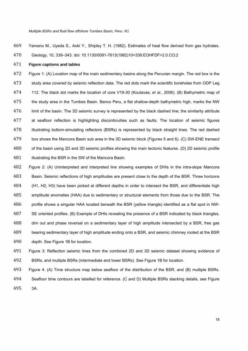
Figure captions and tables 471
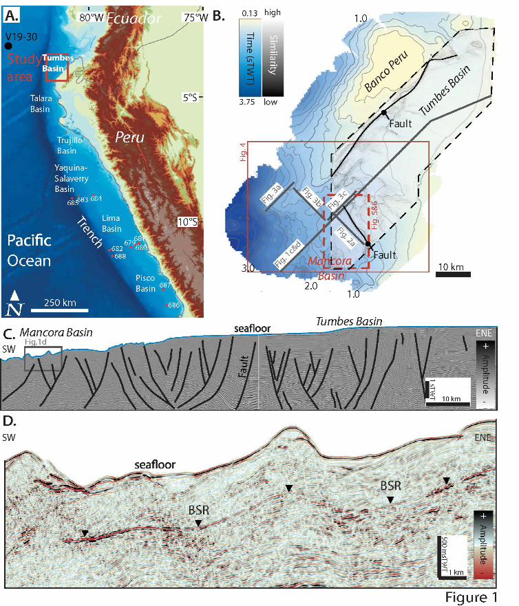
Figure 1: (A) Location map of the main sedimentary basins along the Peruvian margin. The red box is the 472
study area covered by seismic reflection data. The red dots mark the scientific boreholes from ODP Leg 473
112. The black dot marks the location of core V19-30 (Koutavas, et al., 2006). (B) Bathymetric map of 474
the study area in the Tumbes Basin. Banco Peru, a flat shallow-depth bathymetric high, marks the NW 475
limit of the basin. The 3D seismic survey is represented by the black dashed line; the similarity attribute 476
at seafloor reflection is highlighting discontinuities such as faults. The location of seismic figures 477
illustrating bottom-simulating reflectors (BSRs) is represented by black straight lines. The red dashed 478
box shows the Mancora Basin sub area in the 3D seismic block (Figures 5 and 6). (C) SW-ENE transect 479
of the basin using 2D and 3D seismic profiles showing the main tectonic features. (D) 2D seismic profile 480
illustrating the BSR in the SW of the Mancora Basin. 481
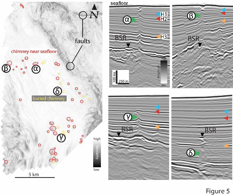
Figure 2: (A) Uninterpreted and interpreted line showing examples of DHIs in the intra-slope Mancora 482
Basin. Seismic reflections of high amplitudes are present close to the depth of the BSR. Three horizons 483
(H1, H2, H3) have been picked at different depths in order to intersect the BSR, and differentiate high 484
amplitude anomalies (HAA) due to sedimentary or structural elements from those due to the BSR. The 485
profile shows a singular HAA located beneath the BSR (yellow triangle) identified as a flat spot in NW-486
SE oriented profiles. (B) Example of DHIs revealing the presence of a BSR indicated by black triangles, 487
dim out and phase reversal on a sedimentary layer of high amplitude intersected by a BSR, free gas 488
bearing sedimentary layer of high amplitude ending onto a BSR, and seismic chimney rooted at the BSR 489
depth. See Figure 1B for location. 490
Figure 3: Reflection seismic lines from the combined 2D and 3D seismic dataset showing evidence of 491
BSRs, and multiple BSRs (intermediate and lower BSRs). See Figure 1B for location. 492
Figure 4: (A) Time structure map below seafloor of the distribution of the BSR, and (B) multiple BSRs. 493
Seafloor time contours are labelled for reference. (C and D) Multiple BSRs stacking details, see Figure 494
3A. 495

Multiple BSRs and fluid flow offshore Tumbes Basin, Peru. R1
19
Figure 5: Similarity attribute map of the seafloor highlighting the location of chimneys at the seafloor (red), 496
and buried chimneys (yellow). Seismic chimneys ending with mounds or pockmarks at the present day 497
seafloor (α and β), and buried chimneys ending with an intra-sedimentary doming (γ) or a patch of HAA 498
(δ). 499
Figure 6: Blended TWT-structure and similarity maps of the seafloor (A) and three horizons (H1, H2, H3) 500
(B, C, D) showing the relationship between faults azimuth and chimneys, the rose diagrams indicating 501
the normal fault trend. The deepest horizon evidenced the highest fault density of the Mancora Basin. 502
Figure 7: Results from a detailed analysis of the base of the gas hydrate stability zone (GHSZ) within the 503
2D seismic dataset. (A) Water depth map assuming 1500 m/s seawater velocity; (B) Gas hydrate 504
stability zone thickness assuming 1800 m/s sediment velocity; (C) Geothermal gradient computed 505
across the mapped BSR. Contours interval is 200 m. 506
Figure 8: Stability conditions for gas hydrate from depth-temperature readings within the study area. 507
Seawater temperature data compiled from World Ocean Database 2009. The theoretical curves are 508
calculated for seawater-methane approximation with different gas compositions using the program 509
CSMHYD of Sloan (1998). 510
Figure 9: Plots of observed upper BSR (black line), intermediate BSR (blue line), and lower BSR (yellow 511
line), and computed positions of the upper BSR for present and glacial temperature and pressure 512
conditions. See Figure 3 for original seismic observation of the BSRs. 513
Figure 10: Diagram showing how tectonic subsidence and sedimentation influence the depth and shape of 514
the BSR in Figure 2A. (A) Initial state; (B) Listric normal fault developement and downward shift of the 515
BSR; (C) Sedimentation and fault reactivation. Dissociation of hydrates (BSR) near the contact with the 516
foot wall; (D) Sedimentation without faults reactivation. Free gas accumulation near the listric fault plane. 517
Table 1: Scenario of base of hydrate stability zone below seafloor for given water depths, different gas 518
composition, and geothermal gradient. Observed BSRs depth is from the Tumbes Basin. 519
520


![New Techniques in Corolling Gas Hydrates [Recovered] Techniques in Corolling Gas Hydrates... · New Techniques in Controlling Gas Hydrates ... Ethane Propane ... • When hydrates](https://static.fdocuments.in/doc/165x107/5b865c467f8b9a195a8ca7ef/new-techniques-in-corolling-gas-hydrates-recovered-techniques-in-corolling-gas.jpg)


