Seismic Arrays presented at the WORKSHOP High Quality Seismic Stations and Networks for Small...
17
Seismic Arrays presented at the WORKSHOP High Quality Seismic Stations and Networks for Small Budgets Volcan, Panama 8-13. March 2004by Jens Havskov, Department of Earth Science University of Bergen Norway
-
Upload
oliver-mckenzie -
Category
Documents
-
view
216 -
download
0
Transcript of Seismic Arrays presented at the WORKSHOP High Quality Seismic Stations and Networks for Small...

Seismic Arrays
presented at the
WORKSHOP
High Quality Seismic Stations and Networks for Small Budgets Volcan, Panama 8-13. March 2004by
Jens Havskov, Department of Earth Science
University of Bergen
Norway

0 0.5 1 1.5 2 2.5
TIME s
S1
S2
S3
S4
S5
S6
S7
S8
S9
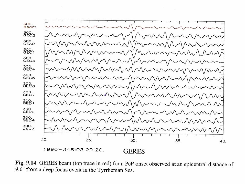
A plane wavefront arrives with apparent slowness p to a rectangular shaped array (the intersection of the wavefront with the surface, where the array is installed, is shown). The angle with respect to North defines the ray arrival azimuth. Right: The waveforms recorded are ideally identical, except for the relative delays. In practice, they present differences due to the added noise and to the local ground heterogeneity

A projection on the incidence vertical plane. As the wavefront advances a distance cΔt, the intersection with the horizontal plane advances Δx, with apparent velocity v. The relations between v and c can be seen from the geometry in the figur as v = c/sin(i)

-2000 -1000 0 1000 2000
-2000
-1000
0
1000
2000
m
ARCES is a small aperture array with 25 stations covering four concentric circles. The diameter of the external ring is about 3 km. The radial spacing of the stations is not uniform in order to deal with different wavelength

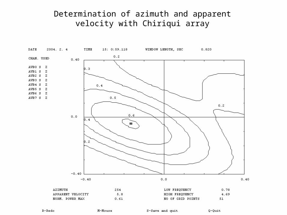
Determination of azimuth and apparent velocity with Chiriqui array

-2000 -1000 0 1000 2000
-2000
-1000
0
1000
2000
m
-300 -200 -100 0 100 200 300
0
100
200
300
m
-25 -20 -15 -10 -5 0 5 10 15 20
wavenumber kx (1/km)
-25
-20
-15
-10
-5
0
5
10
15
20
wav
enu
mb
er k
y (1
/km
)
-50 -40 -30 -20 -10 0 10 20 30 40
wavenumber kx (1/km)
-50
-40
-30
-20
-10
0
10
20
30
40
wav
enu
mb
er k
y (1
/km
)0.1
0.2
0.3
0.4
0.5
0.6
0.7
0.8
0.9
1
1.2
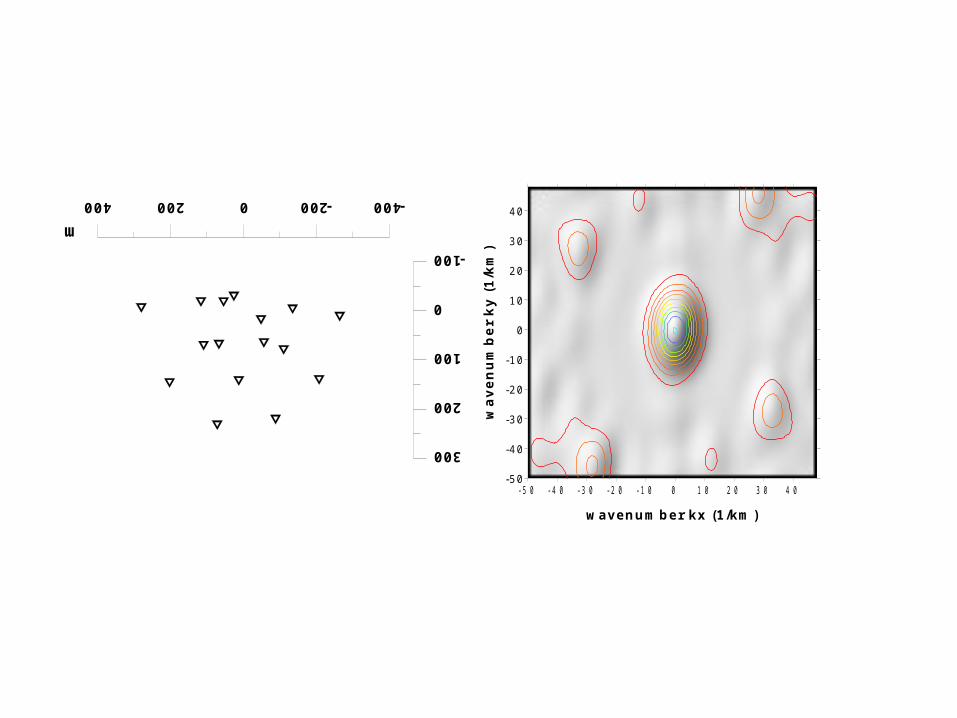
Arrray response function

0 100 200 300
0
40
80
120
160
200
m-50 -40 -30 -20 -10 0 10 20 30 40
wavenumber kx (1/km)
-50
-40
-30
-20
-10
0
10
20
30
40
wav
enu
mb
er k
y (1
/km
)

0 100 200 300 400 500
0
100
200
300
400
500
m
-50 -40 -30 -20 -10 0 10 20 30 40
wavenumber kx (1/km)
-50
-40
-30
-20
-10
0
10
20
30
40
wav
enu
mb
er k
y (1
/km
)
-400-2000200400
-100
0
100
200
300
m-50 -40 -30 -20 -10 0 10 20 30 40
wavenumber kx (1/km)
-50
-40
-30
-20
-10
0
10
20
30
40
wav
enu
mb
er k
y (1
/km
)

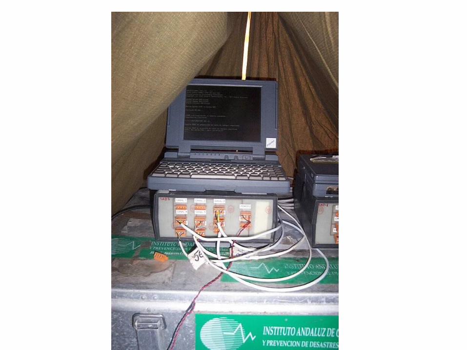
Block diagram of a portable array. It is composed of several modules, one of which is represented. A central box contains an 8-channels antialias filter, a 16 bit-digitizer, a GPS receiver and a power supply for all. The digitizer is controlled by a PC through the parallel port and is synchronized to the GPS time via the serial port. The seismometers have a preamplifier with a low-impedance differential output, so that long connection cables may be used. The recording is made on the PC hard disk.


Potential use of a small seismic array
Improved detection of weak signals
Automatic detection of P and S-wave arrivals
Determination of azimuth
Automatic location
Location of weak emergent arrivals like volcanic tremor
Building a regional location capability in a small area