Communication presented at the WORKSHOP High Quality Seismic Stations and Networks for Small Budgets...
18
Communication presented at the WORKSHOP High Quality Seismic Stations and Networks for Small Budgets Volcan, Panama 8-13. March 2004 by Jens Havskov, Department of Earth Science University of Bergen Norway
-
Upload
aleesha-daniel -
Category
Documents
-
view
214 -
download
0
Transcript of Communication presented at the WORKSHOP High Quality Seismic Stations and Networks for Small Budgets...

Communication
presented at the
WORKSHOP
High Quality Seismic Stations and Networks for Small Budgets
Volcan, Panama 8-13. March 2004
by
Jens Havskov, Department of Earth Science
University of Bergen
Norway
Computer Data storageAnalog to
Digitalconverter
Powersupply
GPS
Communication
Sensor
input
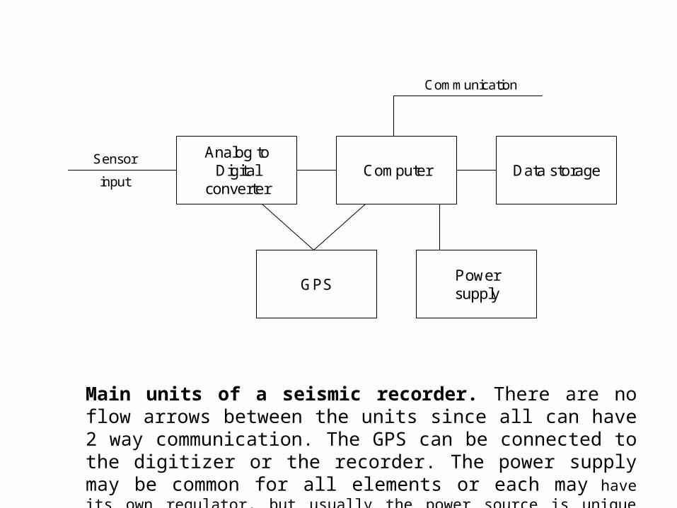
Main units of a seismic recorder. There are no flow arrows between the units since all can have 2 way communication. The GPS can be connected to the digitizer or the recorder. The power supply may be common for all elements or each may have its own regulator, but usually the power source is unique (e.g. a battery).
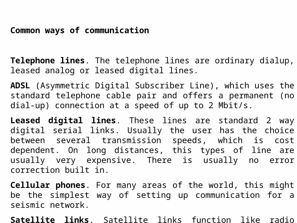
Common ways of communication
Telephone lines. The telephone lines are ordinary dialup, leased analog or leased digital lines.
ADSL (Asymmetric Digital Subscriber Line), which uses the standard telephone cable pair and offers a permanent (no dial-up) connection at a speed of up to 2 Mbit/s.
Leased digital lines. These lines are standard 2 way digital serial links. Usually the user has the choice between several transmission speeds, which is cost dependent. On long distances, this types of line are usually very expensive. There is usually no error correction built in.
Cellular phones. For many areas of the world, this might be the simplest way of setting up communication for a seismic network.
Satellite links. Satellite links function like radio links with the advantage that no line of sight is required. The most common system to use is the Very Small Aperture Terminal (VSAT) system, which has been in operation since 1985
Radio links, can be VHF, UHF or spread spectrum
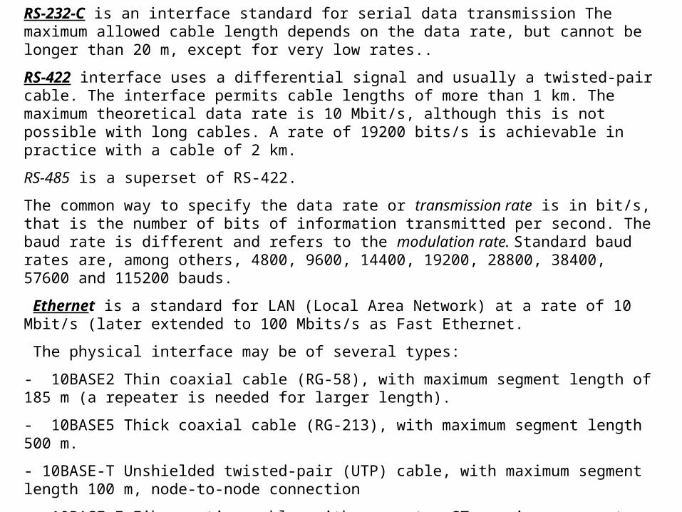
RS-232-C is an interface standard for serial data transmission The maximum allowed cable length depends on the data rate, but cannot be longer than 20 m, except for very low rates..
RS-422 interface uses a differential signal and usually a twisted-pair cable. The interface permits cable lengths of more than 1 km. The maximum theoretical data rate is 10 Mbit/s, although this is not possible with long cables. A rate of 19200 bits/s is achievable in practice with a cable of 2 km.
RS-485 is a superset of RS-422.
The common way to specify the data rate or transmission rate is in bit/s, that is the number of bits of information transmitted per second. The baud rate is different and refers to the modulation rate. Standard baud rates are, among others, 4800, 9600, 14400, 19200, 28800, 38400, 57600 and 115200 bauds.
Ethernet is a standard for LAN (Local Area Network) at a rate of 10 Mbit/s (later extended to 100 Mbits/s as Fast Ethernet.
The physical interface may be of several types:
- 10BASE2 Thin coaxial cable (RG-58), with maximum segment length of 185 m (a repeater is needed for larger length).
- 10BASE5 Thick coaxial cable (RG-213), with maximum segment length 500 m.
- 10BASE-T Unshielded twisted-pair (UTP) cable, with maximum segment length 100 m, node-to-node connection
- 10BASE-F Fiber optics cable, with connector ST, maximum segment length of 2 km.
TCP/IP (Transmission Control Protocol/Internet Protocol) is a standard protocol, which runs on a higher level than the data exchange level. It includes the utilities for virtual terminals (Telnet) and for file transfer (FTP).
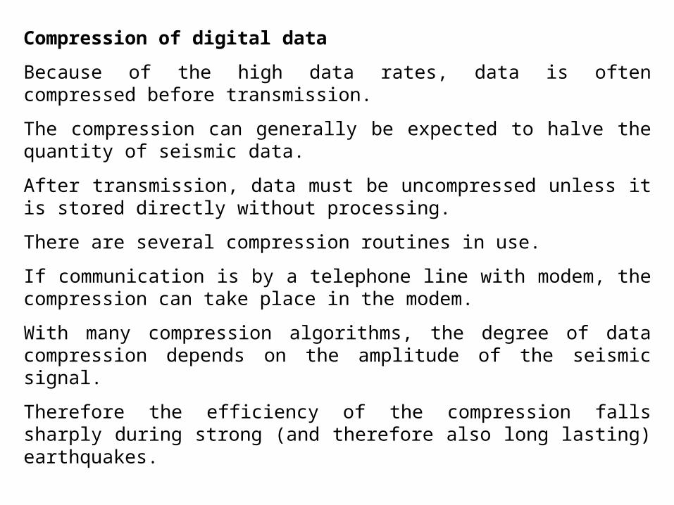
Compression of digital data
Because of the high data rates, data is often compressed before transmission.
The compression can generally be expected to halve the quantity of seismic data.
After transmission, data must be uncompressed unless it is stored directly without processing.
There are several compression routines in use.
If communication is by a telephone line with modem, the compression can take place in the modem.
With many compression algorithms, the degree of data compression depends on the amplitude of the seismic signal.
Therefore the efficiency of the compression falls sharply during strong (and therefore also long lasting) earthquakes.

Error correction methods used with seismic signals
All digital communications experience errors.
In transmission of seismic signals this is particularly fatal since just one bit of error might result in a spike in the data with a value a million times the seismic signal.
One of the principles of error correction is that the data is sent in blocks, e.g. 1 s long, and along with the block of data there is some kind of checksum.
If the checksum does not tally with the received data, a request is sent to retransmit that particular block of data.
A checksum can simply be the sum of all the sample values in one block or more sophisticated algorithms can be used.
Error correction requires duplex transmission lines and local data memory at the remote station
Error correction is built in to TCP/IP
SensorCentralrecorder
SensorPermanent
connection
Sensor
Sensor
Sensor
Sensor
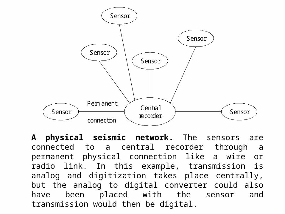
A physical seismic network. The sensors are connected to a central recorder through a permanent physical connection like a wire or radio link. In this example, transmission is analog and digitization takes place centrally, but the analog to digital converter could also have been placed with the sensor and transmission would then be digital.
Drumrecorder
Digital recorderDigital toanalog
convertor
Field station
Time markgenerator
GPS
Field station Field station Field station
Digital transmission
GPS GPSGPS
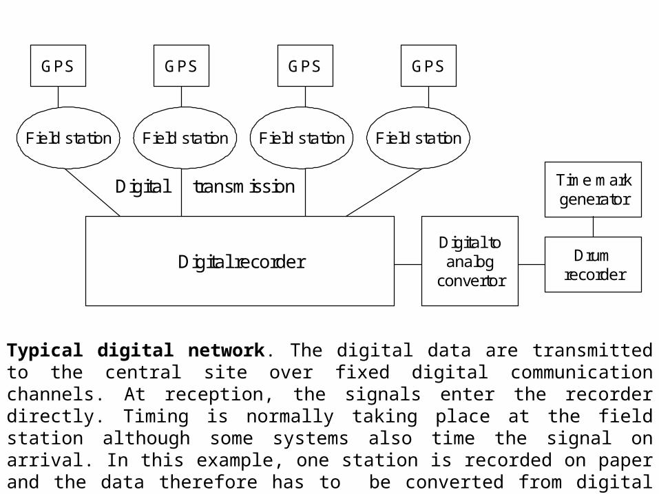
Typical digital network. The digital data are transmitted to the central site over fixed digital communication channels. At reception, the signals enter the recorder directly. Timing is normally taking place at the field station although some systems also time the signal on arrival. In this example, one station is recorded on paper and the data therefore has to be converted from digital to analog. The time mark generator for the drum can use the recorder GPS, if it has one, or it has its own timing reference.
Transceiver Transceiver
Point to point
Transceiver Transceiver
Point to multi point
Transceiver
Transceiver 1
2
3
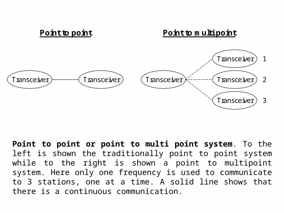
Point to point or point to multi point system. To the left is shown the traditionally point to point system while to the right is shown a point to multipoint system. Here only one frequency is used to communicate to 3 stations, one at a time. A solid line shows that there is a continuous communication.
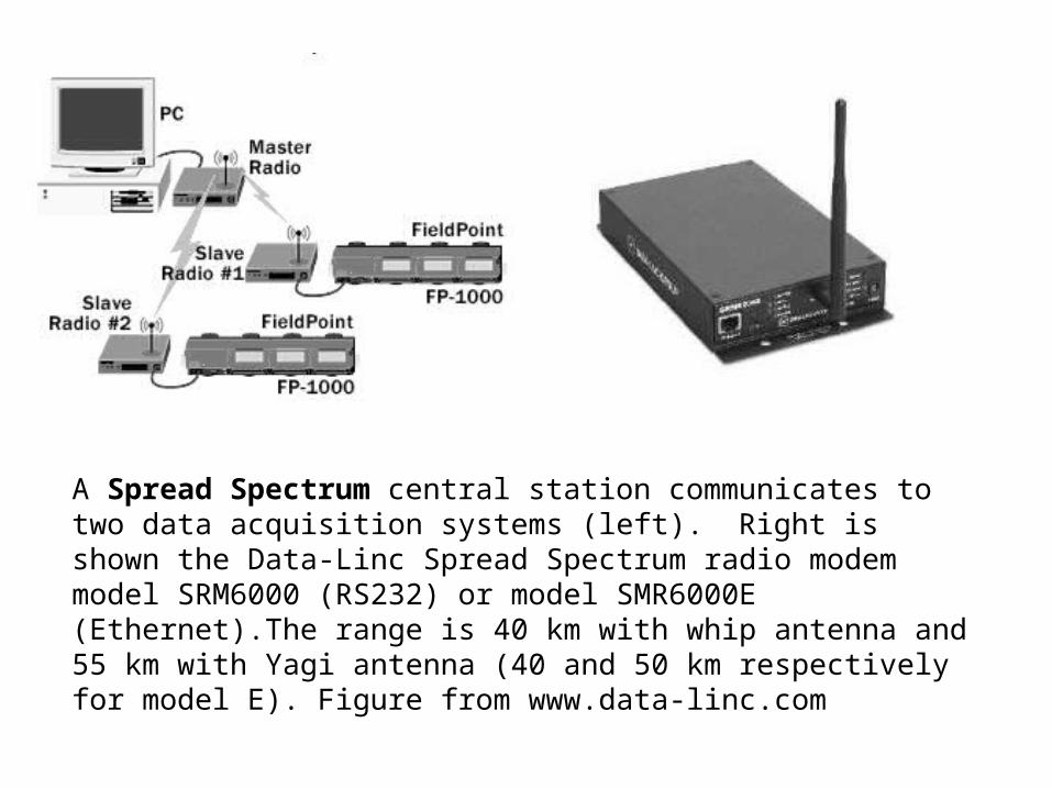
A Spread Spectrum central station communicates to two data acquisition systems (left). Right is shown the Data-Linc Spread Spectrum radio modem model SRM6000 (RS232) or model SMR6000E (Ethernet).The range is 40 km with whip antenna and 55 km with Yagi antenna (40 and 50 km respectively for model E). Figure from www.data-linc.com

Theoretical calculation of the height h required at a distance d over a flat topography to get line of sight. From the geometric scheme on the left, the formula for h is obtained (center) as a function of R (Earth radius) and the distance. The table on the right list the heights needed for some distances.
d (km) h(m)
10 8
20 31
30 71
50 196
70 38
100 785
Repeater 1
Stationtransmitter
Receiver
Stationtransmitter
transmitter
Repeater 2
Receiver
Central station
Receiver
Receiver Receiver Receiver
Multiplexer
Transmitter
Stationtransmitter
Stationtransmitter
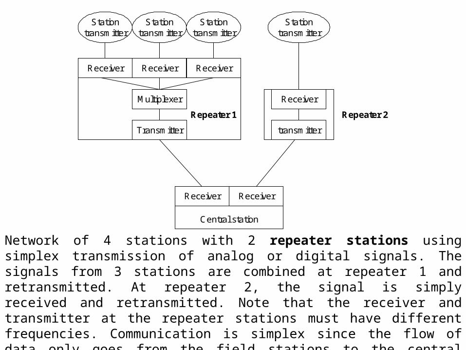
Network of 4 stations with 2 repeater stations using simplex transmission of analog or digital signals. The signals from 3 stations are combined at repeater 1 and retransmitted. At repeater 2, the signal is simply received and retransmitted. Note that the receiver and transmitter at the repeater stations must have different frequencies. Communication is simplex since the flow of data only goes from the field stations to the central station so for the case of digital transmission, there is no error correction, only error check.
Transceiver
Repeater 1
Stationtransceiver
Transceiver
Transceiver
Stationtransceiver
Transceiver
Transceiver
Stationtransceiver
Transceiver
Transceiver
Stationtransceiver
Transceiver
Repeater 2
Transceiver Transceiver Transceiver Transceiver
Central recorder
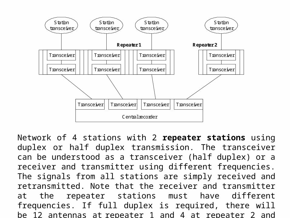
Network of 4 stations with 2 repeater stations using duplex or half duplex transmission. The transceiver can be understood as a transceiver (half duplex) or a receiver and transmitter using different frequencies. The signals from all stations are simply received and retransmitted. Note that the receiver and transmitter at the repeater stations must have different frequencies. If full duplex is required, there will be 12 antennas at repeater 1 and 4 at repeater 2 and half that much for half duplex.

Seismic stationwith local memory
Modem
Dialupphone
RS232ComputerModem
Dialupphone
RS232
Manual dial up to a seismic station for data inspection and/or download. The computer dialing can be any type of computer with a terminal emulator program like Hyper terminal in Windows.
Computer withdata collection
software
Seismicrecorder
Communication network
Seismicrecorder
Seismicrecorder
Seismicrecorder
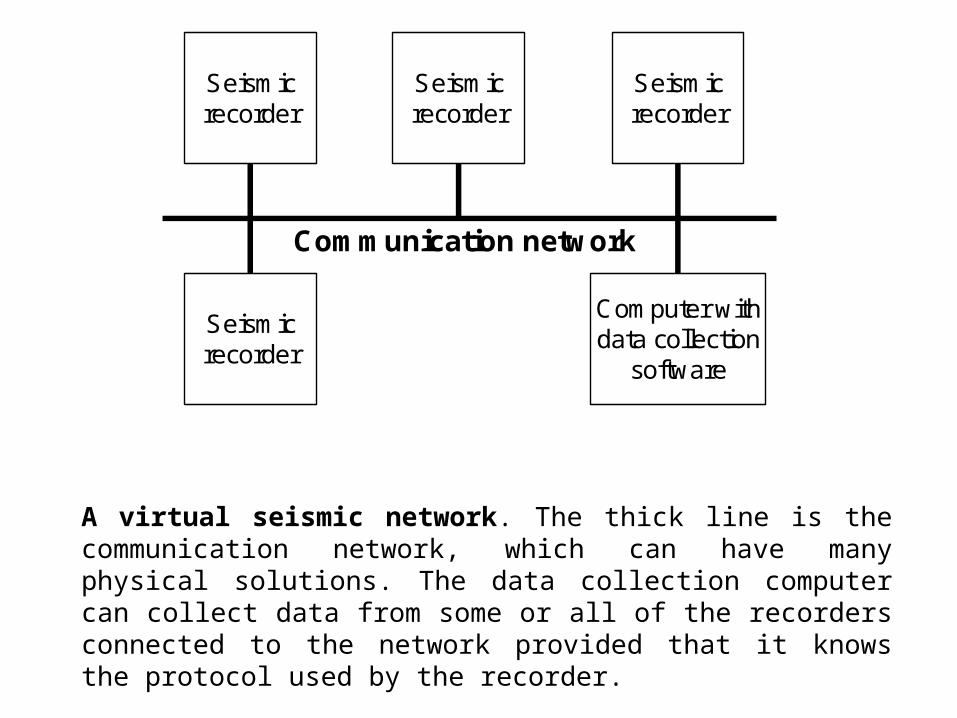
A virtual seismic network. The thick line is the communication network, which can have many physical solutions. The data collection computer can collect data from some or all of the recorders connected to the network provided that it knows the protocol used by the recorder.

TCP/IP based datacollection system forreal time data and
triggeed data
Sensors
Internet and/or local area network
BridgeRS232 to TCP/IP
Digitizer
RS232
Field station
Router
ISDN
Dial up PPP
modemField station
Router
Modem
Router
ISDN
Router
ISDN
Field station Field station
Router
Modem
Field station
Router
Modem
Field station
NetworkWindows
Field station
Broad bandLinux
SensorsSensors
Dial up connection
Different ways of getting a TCP/IP connection to a central data collection system. The thick solid lines indicate permanent Ethernet connections.
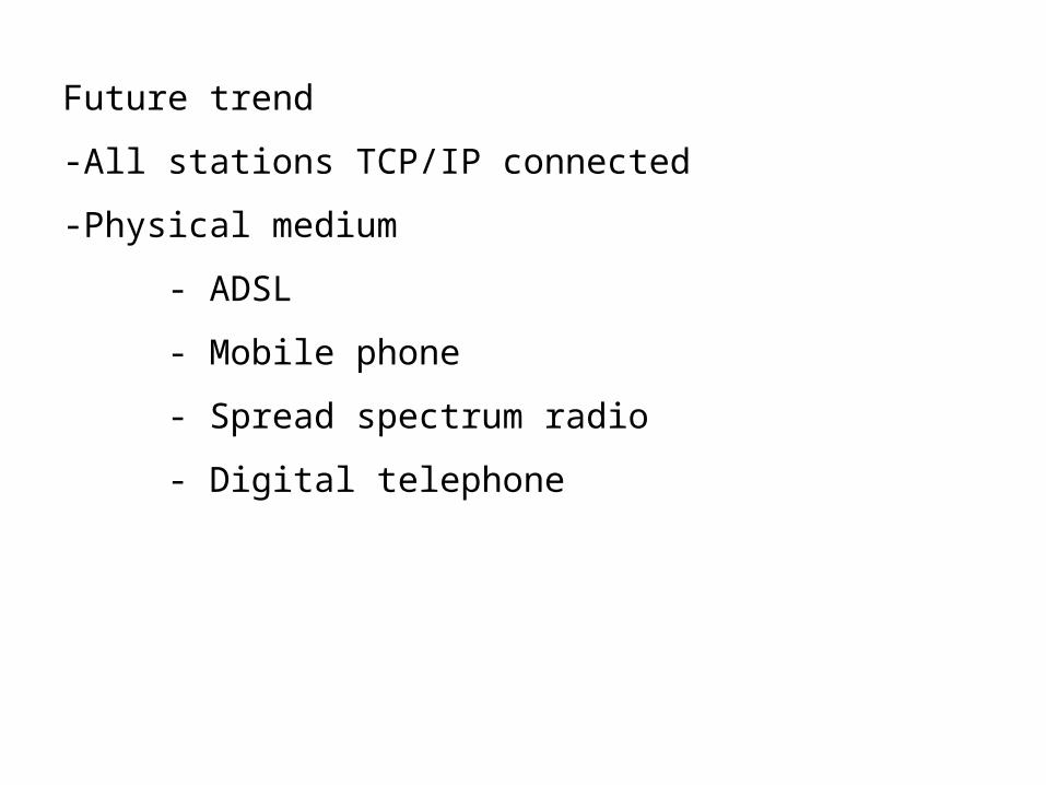
Future trend
-All stations TCP/IP connected
-Physical medium
- ADSL
- Mobile phone
- Spread spectrum radio
- Digital telephone

Mobile phone with internet, TCP/IP (56 kb), operating system and 0.5 gb memory