SECTION POWER SUPPLY, GROUND & CIRCUIT …boredmder.com/FSMs/Nissan/Altima/2002/PG.pdfPOWER SUPPLY,...
72
PG-1 POWER SUPPLY, GROUND & CIRCUIT ELEMENTS K ELECTRICAL CONTENTS C D E F G H I J L M SECTION A B PG Revision: May 2004 2002 Altima POWER SUPPLY ROUTING CIRCUIT ..................... 3 Schematic ............................................................... 3 Wiring Diagram — POWER — ................................ 5 BATTERY POWER SUPPLY — IGNITION SW. IN ANY POSITION ............................................... 5 ACCESSORY POWER SUPPLY — IGNITION SW. IN ACC OR ON ............................................. 9 IGNITION POWER SUPPLY — IGNITION SW. IN ON ................................................................. 10 IGNITION POWER SUPPLY — IGNITION SW. IN ON AND/OR START ....................................... 11 IPDM E/R (INTELLIGENT POWER DISTRIBUTION MODULE ENGINE ROOM) ..................................... 14 System Description ............................................... 14 SYSTEMS CONTROLLED BY IPDM E/R .......... 14 CAN COMMUNICATION LINE CONTROL ........ 14 IPDM E/R STATUS CONTROL .......................... 14 CAN Communication System Description ............. 15 FOR TCS MODELS ........................................... 15 FOR A/T MODELS ............................................. 16 FOR M/T MODELS ............................................ 18 Function of Detecting Ignition Relay Malfunction ... 19 Auto Active Test .................................................... 19 DESCRIPTION ................................................... 19 OPERATION PROCEDURE .............................. 19 INSPECTION IN AUTO ACTIVE TEST MODE ... 20 Schematic ............................................................. 22 IPDM E/R FUSE AND RELAY ARRANGEMENT ... 23 IPDM E/R TERMINAL ARRANGEMENT ........... 23 IPDM E/R Power/Ground Circuit Inspection ......... 23 Removal and Installation of IPDM E/R .................. 24 GROUND CIRCUIT .................................................. 26 Ground Distribution ............................................... 26 MAIN HARNESS ................................................ 26 ENGINE ROOM LH HARNESS ......................... 28 ENGINE ROOM RH HARNESS ......................... 29 ENGINE CONTROL HARNESS (QR25DE) ....... 30 ENGINE CONTROL HARNESS (VQ35DE) ....... 32 BODY HARNESS ............................................... 34 BODY NO. 2 HARNESS .................................... 35 HARNESS ................................................................ 37 Harness Layout ..................................................... 37 HOW TO READ HARNESS LAYOUT ................ 37 OUTLINE ............................................................ 38 MAIN HARNESS ................................................ 39 ENGINE ROOM LH HARNESS ......................... 41 ENGINE ROOM RH HARNESS ......................... 44 ENGINE CONTROL HARNESS (QR25DE) ....... 46 ENGINE CONTROL HARNESS (VQ35DE) ....... 48 BODY HARNESS ............................................... 50 BODY NO. 2 HARNESS .................................... 52 ROOM LAMP HARNESS ................................... 54 FRONT DOOR LH HARNESS ........................... 55 FRONT DOOR RH HARNESS ........................... 55 REAR DOOR LH HARNESS .............................. 56 REAR DOOR RH HARNESS ............................. 56 Wiring Diagram Codes (Cell Codes) ..................... 57 ELECTRICAL UNITS LOCATION ........................... 60 Electrical Units Location ........................................ 60 ENGINE COMPARTMENT ................................. 60 PASSENGER COMPARTMENT ........................ 61 Fuse ....................................................................... 63 Fusible Link ........................................................... 63 Circuit Breaker (Built Into BCM) ............................ 63 HARNESS CONNECTOR ........................................ 64 Description ............................................................. 64 HARNESS CONNECTOR (TAB-LOCKING TYPE) ................................................................. 64 HARNESS CONNECTOR (SLIDE-LOCKING TYPE) ................................................................. 65 JOINT CONNECTOR (J/C) ...................................... 66 Terminal Arrangement ........................................... 66 ELECTRICAL UNITS ............................................... 67 Terminal Arrangement ........................................... 67 SMJ (SUPER MULTIPLE JUNCTION) .................... 68 Terminal Arrangement ........................................... 68 STANDARDIZED RELAY ......................................... 69 Description ............................................................. 69 NORMAL OPEN, NORMAL CLOSED AND
Transcript of SECTION POWER SUPPLY, GROUND & CIRCUIT …boredmder.com/FSMs/Nissan/Altima/2002/PG.pdfPOWER SUPPLY,...

PG-1
POWER SUPPLY, GROUND & CIRCUIT ELEMENTS
K ELECTRICAL
CONTENTS
C
D
E
F
G
H
I
J
L
M
SECTION
A
B
PG
Revision: May 2004 2002 Altima
POWER SUPPLY ROUTING CIRCUIT ...................... 3Schematic ................................................................ 3Wiring Diagram — POWER — ................................. 5
BATTERY POWER SUPPLY — IGNITION SW. IN ANY POSITION ................................................ 5ACCESSORY POWER SUPPLY — IGNITION SW. IN ACC OR ON .............................................. 9IGNITION POWER SUPPLY — IGNITION SW. IN ON .................................................................. 10IGNITION POWER SUPPLY — IGNITION SW. IN ON AND/OR START ........................................11
IPDM E/R (INTELLIGENT POWER DISTRIBUTION MODULE ENGINE ROOM) ...................................... 14
System Description ................................................ 14SYSTEMS CONTROLLED BY IPDM E/R ........... 14CAN COMMUNICATION LINE CONTROL ......... 14IPDM E/R STATUS CONTROL ........................... 14
CAN Communication System Description .............. 15FOR TCS MODELS ............................................ 15FOR A/T MODELS .............................................. 16FOR M/T MODELS ............................................. 18
Function of Detecting Ignition Relay Malfunction ... 19Auto Active Test ..................................................... 19
DESCRIPTION .................................................... 19OPERATION PROCEDURE ............................... 19INSPECTION IN AUTO ACTIVE TEST MODE ... 20
Schematic .............................................................. 22IPDM E/R FUSE AND RELAY ARRANGEMENT ... 23IPDM E/R TERMINAL ARRANGEMENT ............ 23
IPDM E/R Power/Ground Circuit Inspection .......... 23Removal and Installation of IPDM E/R ................... 24
GROUND CIRCUIT ................................................... 26Ground Distribution ................................................ 26
MAIN HARNESS ................................................. 26ENGINE ROOM LH HARNESS .......................... 28ENGINE ROOM RH HARNESS .......................... 29ENGINE CONTROL HARNESS (QR25DE) ........ 30ENGINE CONTROL HARNESS (VQ35DE) ........ 32BODY HARNESS ................................................ 34BODY NO. 2 HARNESS ..................................... 35
HARNESS ................................................................. 37Harness Layout ...................................................... 37
HOW TO READ HARNESS LAYOUT ................. 37OUTLINE ............................................................. 38MAIN HARNESS ................................................. 39ENGINE ROOM LH HARNESS .......................... 41ENGINE ROOM RH HARNESS .......................... 44ENGINE CONTROL HARNESS (QR25DE) ........ 46ENGINE CONTROL HARNESS (VQ35DE) ........ 48BODY HARNESS ................................................ 50BODY NO. 2 HARNESS ..................................... 52ROOM LAMP HARNESS .................................... 54FRONT DOOR LH HARNESS ............................ 55FRONT DOOR RH HARNESS ............................ 55REAR DOOR LH HARNESS ............................... 56REAR DOOR RH HARNESS .............................. 56
Wiring Diagram Codes (Cell Codes) ...................... 57ELECTRICAL UNITS LOCATION ............................ 60
Electrical Units Location ......................................... 60ENGINE COMPARTMENT .................................. 60PASSENGER COMPARTMENT ......................... 61
Fuse ........................................................................ 63Fusible Link ............................................................ 63Circuit Breaker (Built Into BCM) ............................. 63
HARNESS CONNECTOR ......................................... 64Description .............................................................. 64
HARNESS CONNECTOR (TAB-LOCKING TYPE) .................................................................. 64HARNESS CONNECTOR (SLIDE-LOCKING TYPE) .................................................................. 65
JOINT CONNECTOR (J/C) ....................................... 66Terminal Arrangement ............................................ 66
ELECTRICAL UNITS ................................................ 67Terminal Arrangement ............................................ 67
SMJ (SUPER MULTIPLE JUNCTION) ..................... 68Terminal Arrangement ............................................ 68
STANDARDIZED RELAY .......................................... 69Description .............................................................. 69
NORMAL OPEN, NORMAL CLOSED AND

PG-2 Revision: May 2004 2002 Altima
MIXED TYPE RELAYS ........................................ 69TYPE OF STANDARDIZED RELAYS .................. 69
FUSE BLOCK-JUNCTION BOX(J/B) ....................... 71Terminal Arrangement ............................................ 71
FUSE AND FUSIBLE LINK BOX ..............................72Terminal Arrangement .............................................72

POWER SUPPLY ROUTING CIRCUIT
PG-3
C
D
E
F
G
H
I
J
L
M
A
B
PG
Revision: May 2004 2002 Altima
POWER SUPPLY ROUTING CIRCUIT PFP:24110
Schematic EKS002L5
For detailed ground distribution, refer to PG-26, "Ground Distribution" .
WKWA0093E

PG-4
POWER SUPPLY ROUTING CIRCUIT
Revision: May 2004 2002 Altima
WKWA0094E
POWER SUPPLY ROUTING CIRCUIT
PG-5
C
D
E
F
G
H
I
J
L
M
A
B
PG
Revision: May 2004 2002 Altima
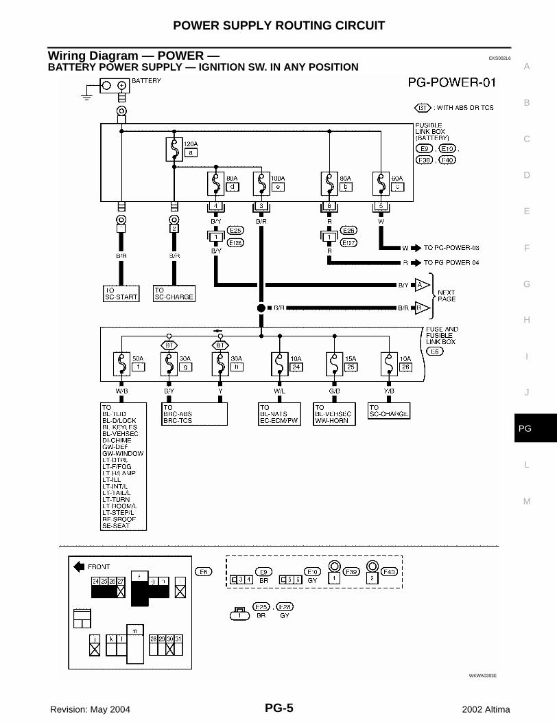
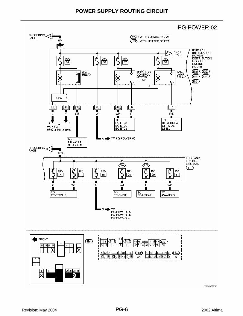
Wiring Diagram — POWER — EKS002L6
BATTERY POWER SUPPLY — IGNITION SW. IN ANY POSITION
WKWA0393E
PG-6
POWER SUPPLY ROUTING CIRCUIT
Revision: May 2004 2002 Altima
WKWA0085E
POWER SUPPLY ROUTING CIRCUIT
PG-7
C
D
E
F
G
H
I
J
L
M
A
B
PG
Revision: May 2004 2002 Altima
WKWA0086E

PG-8
POWER SUPPLY ROUTING CIRCUIT
Revision: May 2004 2002 Altima
WKWA0087E

POWER SUPPLY ROUTING CIRCUIT
PG-9
C
D
E
F
G
H
I
J
L
M
A
B
PG
Revision: May 2004 2002 Altima
ACCESSORY POWER SUPPLY — IGNITION SW. IN ACC OR ON
WKWA0088E

PG-10
POWER SUPPLY ROUTING CIRCUIT
Revision: May 2004 2002 Altima
IGNITION POWER SUPPLY — IGNITION SW. IN ON
WKWA0089E

POWER SUPPLY ROUTING CIRCUIT
PG-11
C
D
E
F
G
H
I
J
L
M
A
B
PG
Revision: May 2004 2002 Altima
IGNITION POWER SUPPLY — IGNITION SW. IN ON AND/OR START
WKWA0090E

PG-12
POWER SUPPLY ROUTING CIRCUIT
Revision: May 2004 2002 Altima
WKWA0091E

POWER SUPPLY ROUTING CIRCUIT
PG-13
C
D
E
F
G
H
I
J
L
M
A
B
PG
Revision: May 2004 2002 Altima
WKWA0092E

PG-14
IPDM E/R (INTELLIGENT POWER DISTRIBUTION MODULE ENGINE ROOM)
Revision: May 2004 2002 Altima
IPDM E/R (INTELLIGENT POWER DISTRIBUTION MODULE ENGINE ROOM)PFP:284B7
System Description EKS002L7
● IPDM E/R (Intelligent Power Distribution Module Engine Room) integrates the relay box and fuse blockwhich were originally placed in engine compartment. It controls integrated relay via IPDM E/R control cir-cuit.
● IPDM E/R-integrated control circuit performs ON-OFF operation of relay, CAN communication control, oilpressure switch signal reception, etc.
● It controls operation of each electrical part via BCM and CAN communication lines.CAUTION:All IPDM E/R-integrated relays cannot be removed.
SYSTEMS CONTROLLED BY IPDM E/R1. Lamp controlUsing CAN communication line, it receives signal from BCM and controls the following lamps:● Headlamps (Hi, Lo)● Parking lamps● Tail lamps● Front fog lamps2. Wiper controlUsing CAN communication line, it receives signals from BCM and controls the front wipers.3. Rear window defogger relay controlUsing CAN communication line, it receives signals from BCM and controls the rear window defogger relay.4. A/C compressor controlUsing CAN communication line, it receives signal from ECM and controls the A/C relay.5. Cooling fan controlUsing CAN communication line, it receives signal from ECM and controls cooling fan relay.
CAN COMMUNICATION LINE CONTROLWith CAN communication, by connecting each control unit using two communication lines (CAN L-line, CANH-line), it is possible to transmit maximum amount of information with minimum wiring. Each control unit cantransmit and receive data, and read necessary information only.1. Fail-safe control
● When CAN communication with other control units is impossible, IPDM E/R performs fail-safe control.After CAN communication recovers normally, it also returns to normal control.
● Operation of control parts by IPDM E/R during fail-safe mode is as follows:
IPDM E/R STATUS CONTROLIn order to save power, IPDM E/R switches status by itself based on each operating condition.1. CAN communication status
● CAN communication is normally performed with other control units.● Individual unit control by IPDM E/R is normally performed.
Controlled parts Fail-safe mode
Headlamps Headlamp relay (Lo) ON
Front fog lamps Front fog lamp relay OFF
Tail and parking lamps Tail lamp relay OFF
Front wipersUntil ignition switch is turned OFF, status immediately before fail-safe control is performed is maintained.
Rear window defogger Rear window defogger relay OFF
Cooling fan Cooling fan (HI) ON
A/C compressor A/C relay OFF

IPDM E/R (INTELLIGENT POWER DISTRIBUTION MODULE ENGINE ROOM)
PG-15
C
D
E
F
G
H
I
J
L
M
A
B
PG
Revision: May 2004 2002 Altima
● When sleep request signal is received from BCM, mode is switched to sleep waiting status.2. Sleep waiting status
● Process to stop CAN communication is activated.● All systems controlled by IPDM E/R are stopped. When 3 seconds have elapsed after CAN communi-
cation with other control units is stopped, mode switches to sleep status.3. Sleep status
● IPDM E/R operates in low current-consumption mode.● CAN communication is stopped.● When a change in CAN communication line is detected, mode switches to CAN communication status.
CAN Communication System Description EKS002L8
CAN (Controller Area Network) is a serial communication line for real time application. It is an on-vehicle mul-tiplex communication line with high data communication speed and excellent error detection ability. Many elec-tronic control units are equipped onto a vehicle, and each control unit shares information and links with othercontrol units during operation (not independent). In CAN communication, control units are connected with 2communication lines (CAN H line, CAN L line) allowing a high rate of information transmission with less wiring.Each control unit transmits/receives data but selectively reads required data only.
FOR TCS MODELSSystem diagram
Input/output signal chartT: Transmit R: Receive
LKIA0015E
Signals ECM TCMCOMBINA-
TION METER
BCMABS/TCS
control unitIPDM E/R
Engine speed signal T R R
Engine coolant temperature signal T R
Accelerator pedal position signal T
Fuel consumption monitor signal T R
A/T warning lamp signal T R
A/T position indicator signal R R R(R range only) R
ABS operation signal R T
TCS operation signal R R T
Air conditioner switch signal R T
Air conditioner compressor signal R T
A/C compressor request signal T R
Cooling fan motor operation signal R T
Cooling fan speed request signal T R
Position lights request R T R
Position lights status R T
Low beam request T R

PG-16
IPDM E/R (INTELLIGENT POWER DISTRIBUTION MODULE ENGINE ROOM)
Revision: May 2004 2002 Altima
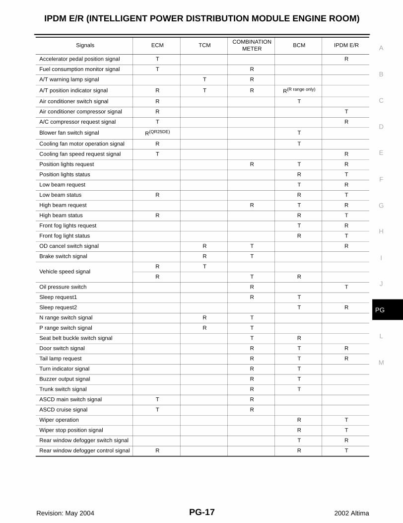
FOR A/T MODELSSystem diagram
Input/output signal chartT: Transmit R: Receive
Low beam status R R T
High beam request R T R
High beam status R R T
Front fog lights request T R
Front fog light status R T
OD cancel switch signal R T R
Brake switch signal R T
Vehicle speed signalR T
R T R
Oil pressure switch R T
Sleep request1 R T
Sleep request2 T R
N range switch signal R T
P range switch signal R T
Seat belt buckle switch signal T R
Door switch signal R T R
Tail lamp request R T R
Turn indicator signal R T
Buzzer output signal R T
Trunk switch signal R T
ASCD main switch signal T R
ASCD cruise signal T R
Wiper operation R T
Wiper stop position signal R T
Rear window defogger switch signal T R
Rear window defogger control sig-nal
R R T
Signals ECM TCMCOMBINA-
TION METER
BCMABS/TCS
control unitIPDM E/R
LKIA0017E
Signals ECM TCMCOMBINATION
METERBCM IPDM E/R
Engine speed signal T R
Engine coolant temperature signal T R
IPDM E/R (INTELLIGENT POWER DISTRIBUTION MODULE ENGINE ROOM)
PG-17
C
D
E
F
G
H
I
J
L
M
A
B
PG
Revision: May 2004 2002 Altima
Accelerator pedal position signal T R
Fuel consumption monitor signal T R
A/T warning lamp signal T R
A/T position indicator signal R T R R(R range only)
Air conditioner switch signal R T
Air conditioner compressor signal R T
A/C compressor request signal T R
Blower fan switch signal R(QR25DE) T
Cooling fan motor operation signal R T
Cooling fan speed request signal T R
Position lights request R T R
Position lights status R T
Low beam request T R
Low beam status R R T
High beam request R T R
High beam status R R T
Front fog lights request T R
Front fog light status R T
OD cancel switch signal R T R
Brake switch signal R T
Vehicle speed signalR T
R T R
Oil pressure switch R T
Sleep request1 R T
Sleep request2 T R
N range switch signal R T
P range switch signal R T
Seat belt buckle switch signal T R
Door switch signal R T R
Tail lamp request R T R
Turn indicator signal R T
Buzzer output signal R T
Trunk switch signal R T
ASCD main switch signal T R
ASCD cruise signal T R
Wiper operation R T
Wiper stop position signal R T
Rear window defogger switch signal T R
Rear window defogger control signal R R T
Signals ECM TCMCOMBINATION
METERBCM IPDM E/R

PG-18
IPDM E/R (INTELLIGENT POWER DISTRIBUTION MODULE ENGINE ROOM)
Revision: May 2004 2002 Altima
FOR M/T MODELSSystem diagram
Input/output signal chartT: Transmit R: Receive
LKIA0018E
Signals ECMCOMBINATION
METERBCM IPDM E/R
Engine speed signal T
Engine coolant temperature signal T
Fuel consumption monitor signal T
Air conditioner switch signal R T
Air conditioner compressor signal R T
A/C compressor request signal T R
Blower fan switch signal R(QR25DE) T
Cooling fan motor operation signal R T
Cooling fan speed request signal T R
Position lights request R T R
Position lights status R T
Low beam request T R
Low beam status R R T
High beam request R T R
High beam status R R T
Front fog lights request T R
Front fog light status R T
Vehicle speed signal R T
Oil pressure switch R T
Sleep request1 R T
Sleep request2 T R
Seat belt buckle switch signal T R
Door switch signal R T R
Tail lamp request R T R
Turn indicator signal R T
Buzzer output signal R T
Trunk switch signal R T
ASCD main switch signal T R
ASCD cruise signal T R
Wiper operation R T
Wiper stop position signal R T

IPDM E/R (INTELLIGENT POWER DISTRIBUTION MODULE ENGINE ROOM)
PG-19
C
D
E
F
G
H
I
J
L
M
A
B
PG
Revision: May 2004 2002 Altima
Function of Detecting Ignition Relay Malfunction EKS002L9
● When contact point of integrated ignition relay is stuck and cannot be turned OFF, IPDM E/R turns ON tailand parking lamps for 10 minutes to indicate IPDM E/R malfunction.
Auto Active Test EKS002LA
DESCRIPTION● In auto active test mode, operation inspection can be performed when IPDM E/R sends a drive signal to
the following systems:– Rear window defogger– Front wipers– Tail and parking lamps– Front fog lamps– Headlamps (Hi, Lo)– A/C compressor (magnet clutch)– Cooling fan
OPERATION PROCEDURE1. Close hood and lift wiper arms away from windshield (to prevent glass damage by wiper operation).
NOTE:When auto active test is performed with hood opened, sprinkle water on windshield beforehand.
2. Turn ignition switch OFF.3. Turn ignition switch ON and, within 10 seconds, press front door switch LH ten times. Then turn ignition
switch OFF.CAUTION:Close front door RH.
4. Turn ignition switch ON.5. When auto active test mode is actuated, horn chirps once, and oil pressure warning lamp starts blinking.6. After a series of operations is repeated three times, auto active test is completed.
NOTE:When auto active test mode has to be cancelled halfway, turn ignition switch OFF.CAUTION:Be sure to inspect DI-38, "Oil Pressure Warning Lamp Stays Off (Ignition Switch ON)" and BL-28,"Door Switch Check" when the auto active test cannot be performed.
Rear window defogger switch signal T R
Rear window defogger control signal R R T
Signals ECMCOMBINATION
METERBCM IPDM E/R

PG-20
IPDM E/R (INTELLIGENT POWER DISTRIBUTION MODULE ENGINE ROOM)
Revision: May 2004 2002 Altima
INSPECTION IN AUTO ACTIVE TEST MODE● When auto active test mode is actuated, the following seven steps are repeated three times.
Concept of Auto Active Test● IPDM E/R actuates auto active test mode when it receives door switch signal from BCM via CAN commu-
nication line. Therefore, when auto active test mode is activated successfully, CAN communicationbetween IPDM E/R and BCM is normal.
● If any of systems controlled by IPDM E/R cannot be operated, possible cause can be easily diagnosedusing auto active test.
Diagnosis chart in auto active test mode
WKIA0117E
Symptom Inspection contents Possible cause
Any of front wipers, tail and parking lamps, front fog lamps, and headlamps (Hi, Lo) do not operate.
Perform auto active test. Does system in question operate?
OK ● BCM signal input system
NG
● Lamp/motor malfunction
● Lamp/motor ground system malfunction
● Harness/connector malfunction between IPDM E/R and system in question
● IPDM E/R (integrated relay) malfunction
Rear window defogger does not operate.
Perform auto active test. Does rear win-dow defogger oper-ate?
OK ● BCM signal input system
NG
● Rear window defogger relay system
● Open circuit of rear window defogger
● IPDM E/R malfunction
A/C compressor does not operate.
Perform auto active test. Does magnet clutch operate?
OK
● BCM signal input system
● CAN communication signal between BCM and ECM.
● CAN communication signal between ECM and IPDM E/R
● BCM
● ECM
NG
● Magnet clutch malfunction
● Harness/connector malfunction between IPDM E/R and magnet clutch
● IPDM E/R (integrated relay) malfunction
Cooling fan does not operate.
Perform auto active test. Does cooling fan operate?
OK
● ECM signal input system
● CAN communication signal between ECM and IPDM E/R
● ECM
NG
● Cooling fan motor malfunction
● Harness/connector malfunction between IPDM E/R and cooling fan motor
● IPDM E/R (integrated relay) malfunction

IPDM E/R (INTELLIGENT POWER DISTRIBUTION MODULE ENGINE ROOM)
PG-21
C
D
E
F
G
H
I
J
L
M
A
B
PG
Revision: May 2004 2002 Altima
Oil pressure warning lamp does not operate.
Perform auto active test. Does oil pres-sure warning lamp blink?
OK● Harness/connector malfunction between IPDM E/R and oil pressure switch
● Oil pressure switch malfunction
NG● CAN communication signal between IPDM E/R and combination meter
● Combination meter
Symptom Inspection contents Possible cause
PG-22
IPDM E/R (INTELLIGENT POWER DISTRIBUTION MODULE ENGINE ROOM)
Revision: May 2004 2002 Altima
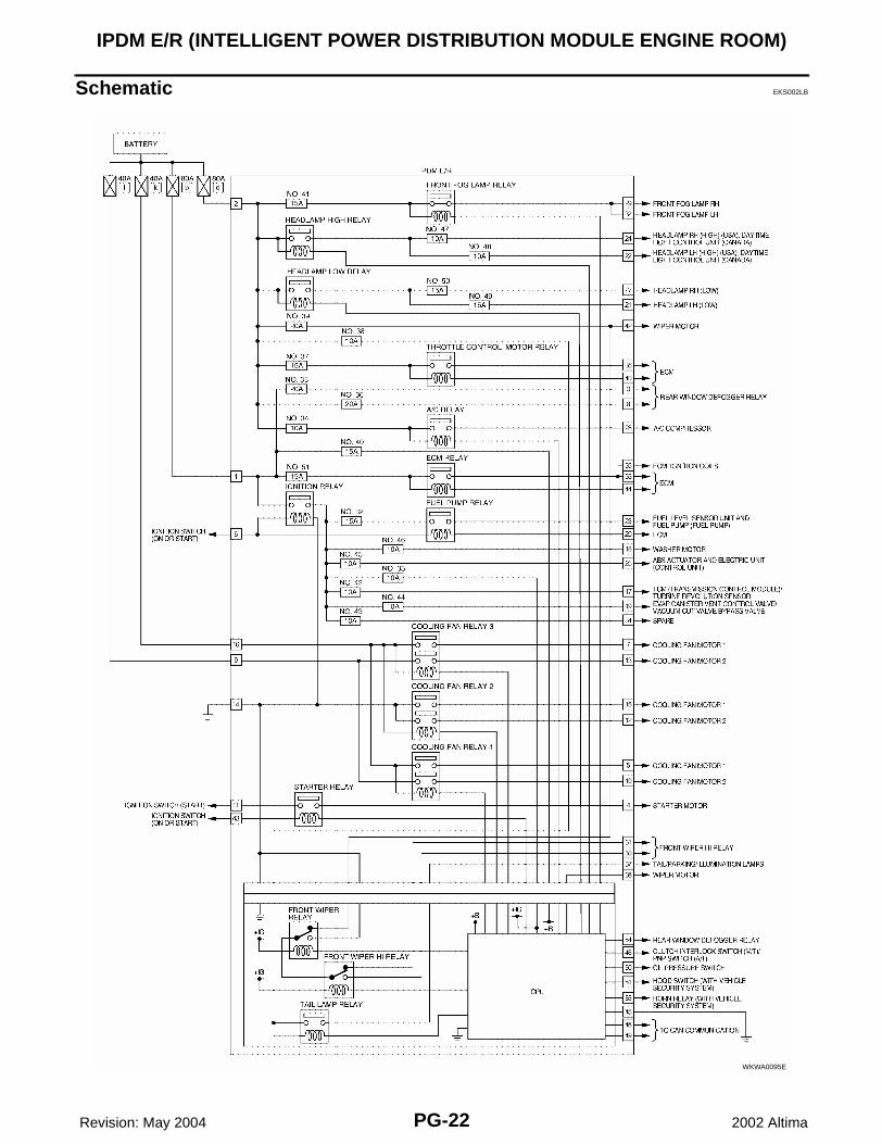
Schematic EKS002LB
WKWA0095E

IPDM E/R (INTELLIGENT POWER DISTRIBUTION MODULE ENGINE ROOM)
PG-23
C
D
E
F
G
H
I
J
L
M
A
B
PG
Revision: May 2004 2002 Altima
IPDM E/R FUSE AND RELAY ARRANGEMENT
IPDM E/R TERMINAL ARRANGEMENT
IPDM E/R Power/Ground Circuit Inspection EKS002LC
1. FUSE AND FUSIBLE LINK INSPECTION
● Check that the following fusible links or IPDM E/R fuses are not blown.
OK or NG?OK >> GO TO 2.NG >> Replace fuse or fusible link.
WKIA0173E
WKIA0116E
Terminal No. Signal name Fuse, fusible link No.
1, 2 Battery power F/L–b, F/L–d, Fuse No. 40
– Ignition power Fuse No. 33

PG-24
IPDM E/R (INTELLIGENT POWER DISTRIBUTION MODULE ENGINE ROOM)
Revision: May 2004 2002 Altima
2. POWER CIRCUIT INSPECTION
Disconnect IPDM E/R harness connector E120. Measure voltage between IPDM E/R harness connector E120terminals 1 (R), 2 (B/Y) and body ground.
OK or NG?OK >> GO TO 3.NG >> Replace IPDM E/R power circuit harness.
3. GROUND CIRCUIT INSPECTION
Disconnect IPDM E/R harness connectors E121 and E123. Checkcontinuity between IPDM E/R harness connectors E123 terminal 14(B), E121 terminal 45 (B) and body ground.
OK or NG?OK >> NormalNG >> Replace ground circuit harness of IPDM E/R.
Removal and Installation of IPDM E/R EKS002LD
1. Disconnect the negative battery cable.2. Remove 2 bolts and position coolant reservoir aside.3. Remove IPDM E/R upper cover.
4. Remove IPDM E/R harness cover.
Terminal No. Signal name Ignition switch Voltage (V)
1, 2 Battery power OFF Approx. 12
WKIA0118E
Terminal No. Signal name Ignition switch Continuity
14, 45 Ground OFF YES
WKIA0119E
WKIA0120E
WKIA0121E

IPDM E/R (INTELLIGENT POWER DISTRIBUTION MODULE ENGINE ROOM)
PG-25
C
D
E
F
G
H
I
J
L
M
A
B
PG
Revision: May 2004 2002 Altima
5. Release 2 clips and pull IPDM E/R up from case.6. Disconnect IPDM E/R connectors and then remove it.
WKIA0122E

PG-26
GROUND CIRCUIT
Revision: May 2004 2002 Altima
GROUND CIRCUIT PFP:24080
Ground Distribution EKS002LE
MAIN HARNESS
WKIA0080E

GROUND CIRCUIT
PG-27
C
D
E
F
G
H
I
J
L
M
A
B
PG
Revision: May 2004 2002 Altima
WKIA0081E

PG-28
GROUND CIRCUIT
Revision: May 2004 2002 Altima
ENGINE ROOM LH HARNESS
WKIA0354E
GROUND CIRCUIT
PG-29
C
D
E
F
G
H
I
J
L
M
A
B
PG
Revision: May 2004 2002 Altima
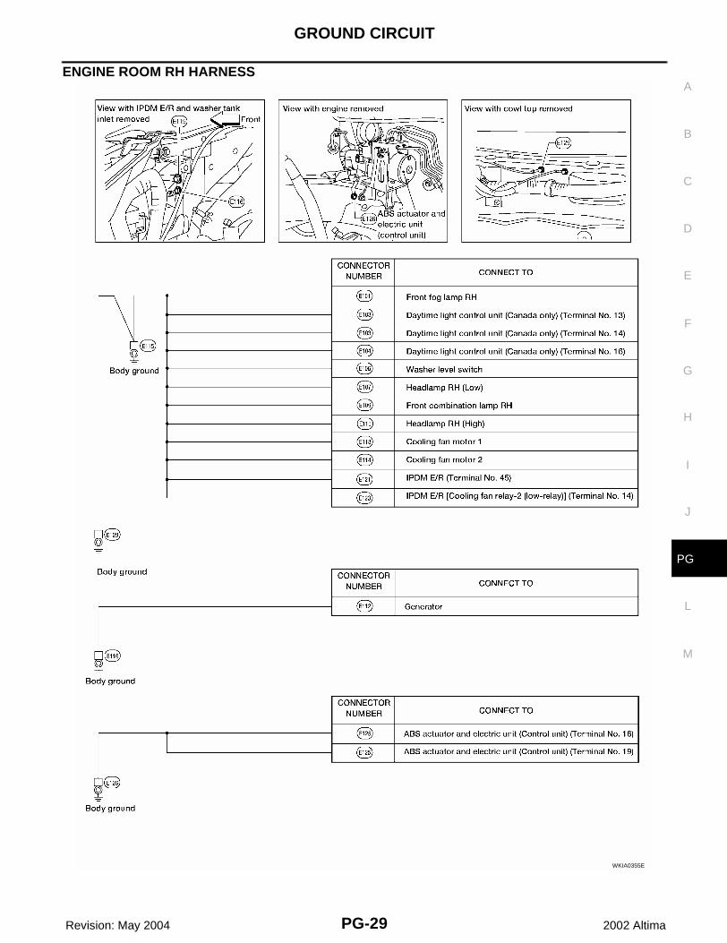
ENGINE ROOM RH HARNESS
WKIA0355E

PG-30
GROUND CIRCUIT
Revision: May 2004 2002 Altima
ENGINE CONTROL HARNESS (QR25DE)
WKIA0084E

GROUND CIRCUIT
PG-31
C
D
E
F
G
H
I
J
L
M
A
B
PG
Revision: May 2004 2002 Altima
WKIA0085E

PG-32
GROUND CIRCUIT
Revision: May 2004 2002 Altima
ENGINE CONTROL HARNESS (VQ35DE)
WKIA0086E

GROUND CIRCUIT
PG-33
C
D
E
F
G
H
I
J
L
M
A
B
PG
Revision: May 2004 2002 Altima
WKIA0087E

PG-34
GROUND CIRCUIT
Revision: May 2004 2002 Altima
BODY HARNESS
WKIA0088E

GROUND CIRCUIT
PG-35
C
D
E
F
G
H
I
J
L
M
A
B
PG
Revision: May 2004 2002 Altima
BODY NO. 2 HARNESS
WKIA0089E

PG-36
GROUND CIRCUIT
Revision: May 2004 2002 Altima
WKIA0090E
HARNESS
PG-37
C
D
E
F
G
H
I
J
L
M
A
B
PG
Revision: May 2004 2002 Altima
HARNESS PFP:24010
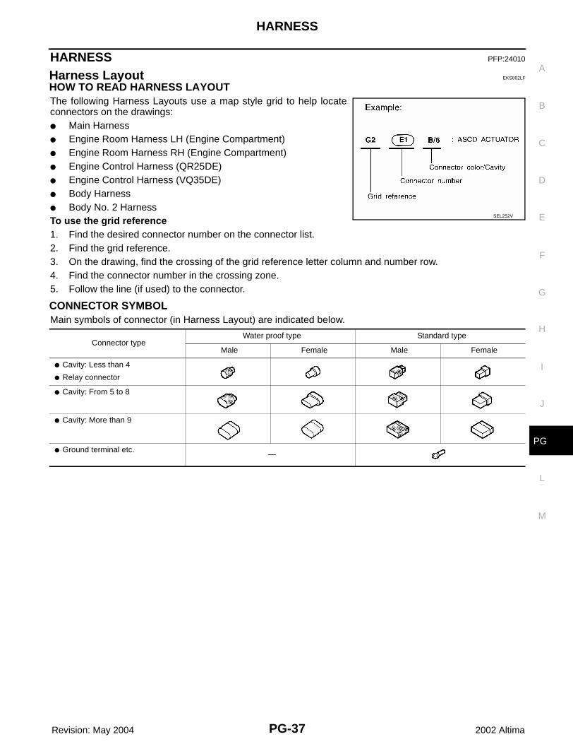
Harness Layout EKS002LF
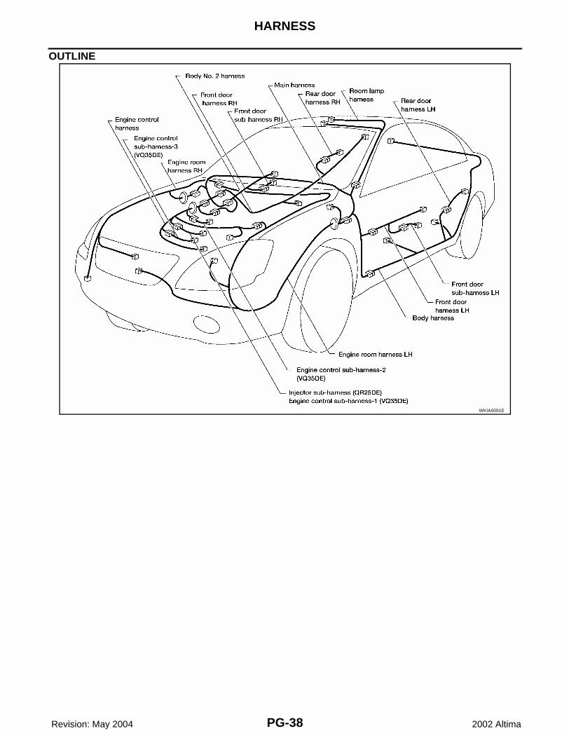
HOW TO READ HARNESS LAYOUT The following Harness Layouts use a map style grid to help locateconnectors on the drawings:● Main Harness● Engine Room Harness LH (Engine Compartment)● Engine Room Harness RH (Engine Compartment)● Engine Control Harness (QR25DE)● Engine Control Harness (VQ35DE)● Body Harness● Body No. 2 HarnessTo use the grid reference1. Find the desired connector number on the connector list.2. Find the grid reference.3. On the drawing, find the crossing of the grid reference letter column and number row.4. Find the connector number in the crossing zone.5. Follow the line (if used) to the connector.
CONNECTOR SYMBOLMain symbols of connector (in Harness Layout) are indicated below.
SEL252V
Connector typeWater proof type Standard type
Male Female Male Female
● Cavity: Less than 4
● Relay connector
● Cavity: From 5 to 8
● Cavity: More than 9
● Ground terminal etc. —
PG-38
HARNESS
Revision: May 2004 2002 Altima
OUTLINE
WKIA0091E

HARNESS
PG-39
C
D
E
F
G
H
I
J
L
M
A
B
PG
Revision: May 2004 2002 Altima
MAIN HARNESS
WKIA0097E

PG-40
HARNESS
Revision: May 2004 2002 Altima
WKIA0098E

HARNESS
PG-41
C
D
E
F
G
H
I
J
L
M
A
B
PG
Revision: May 2004 2002 Altima
ENGINE ROOM LH HARNESS
WKIA0099E

PG-42
HARNESS
Revision: May 2004 2002 Altima
WKIA0356E

HARNESS
PG-43
C
D
E
F
G
H
I
J
L
M
A
B
PG
Revision: May 2004 2002 Altima
Passenger Compartment
WKIA0101E

PG-44
HARNESS
Revision: May 2004 2002 Altima
ENGINE ROOM RH HARNESS
WKIA0110E

HARNESS
PG-45
C
D
E
F
G
H
I
J
L
M
A
B
PG
Revision: May 2004 2002 Altima
WKIA0357E

PG-46
HARNESS
Revision: May 2004 2002 Altima
ENGINE CONTROL HARNESS (QR25DE)
WKIA0112E

HARNESS
PG-47
C
D
E
F
G
H
I
J
L
M
A
B
PG
Revision: May 2004 2002 Altima
WKIA0113E

PG-48
HARNESS
Revision: May 2004 2002 Altima
ENGINE CONTROL HARNESS (VQ35DE)
WKIA0114E

HARNESS
PG-49
C
D
E
F
G
H
I
J
L
M
A
B
PG
Revision: May 2004 2002 Altima
WKIA0115E

PG-50
HARNESS
Revision: May 2004 2002 Altima
BODY HARNESS
WKIA0102E

HARNESS
PG-51
C
D
E
F
G
H
I
J
L
M
A
B
PG
Revision: May 2004 2002 Altima
WKIA0103E

PG-52
HARNESS
Revision: May 2004 2002 Altima
BODY NO. 2 HARNESS
WKIA0104E

HARNESS
PG-53
C
D
E
F
G
H
I
J
L
M
A
B
PG
Revision: May 2004 2002 Altima
WKIA0105E
PG-54
HARNESS
Revision: May 2004 2002 Altima
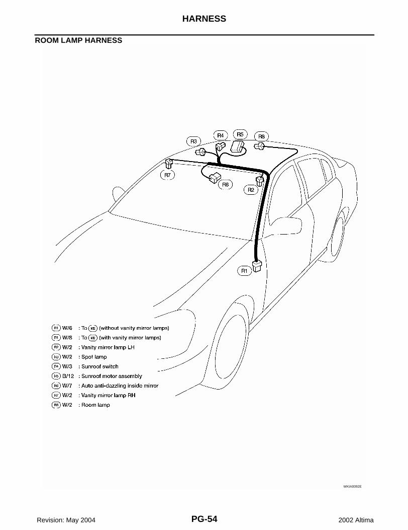
ROOM LAMP HARNESS
WKIA0092E

HARNESS
PG-55
C
D
E
F
G
H
I
J
L
M
A
B
PG
Revision: May 2004 2002 Altima
FRONT DOOR LH HARNESS
FRONT DOOR RH HARNESSWKIA0093E
WKIA0094E

PG-56
HARNESS
Revision: May 2004 2002 Altima
REAR DOOR LH HARNESS
REAR DOOR RH HARNESSWKIA0095E
WKIA0096E

HARNESS
PG-57
C
D
E
F
G
H
I
J
L
M
A
B
PG
Revision: May 2004 2002 Altima
Wiring Diagram Codes (Cell Codes) EKS002LG
Use the chart below to find out what each wiring diagram code stands for.Refer to the wiring diagram code in the alphabetical index to find the location (page number) of each wiringdiagram.
Code Section Wiring Diagram Name
1STSIG AT A/T 1st Signal
2NDSIG AT A/T 2nd Signal
3RDSIG AT A/T 3rd Signal
4THSIG AT A/T 4th Signal
A/C,A ATC Auto Air Conditioner
A/C,M MTC Manual Air Conditioner
A/LIGHT LT Auto Light Control
ABS BRC Anti-Lock Brake System
APPS1 EC Accelerator Pedal Position Sensor
APPS2 EC Accelerator Pedal Position Sensor
APPS3 EC Accelerator Pedal Position Sensor
ASCBOF EC ASCD Brake Switch
ASC/BS EC ASCD Brake Switch
ASCIND EC ASCD Indicator
ASC/SW EC ASCD Steering Switch
AT/IND DI A/T Indicator Lamp
AUDIO AV Audio
B/COMP DI Board Computer
BAF/TS AT A/T Fluid Temperature Sensor and TCM Power Supply
BACK/L LT Back-up Lamp
BRK/SW EC Brake Switch
BYPS/V EC Vacuum Cut Valve Bypass Valve
CAN AT CAN Communication Line
CAN EC CAN Communication Line
CAN LAN CAN System
CHARGE SC Charging System
CHIME DI Warning Chime
CIGAR WW Cigarette Lighter
COOL/F EC Cooling Fan Control
D/LOCK BL Power Door Lock
DEF GW Rear Window Defogger
DLC EC Data Link Connector
DTRL LT Headlamp - With Daytime Light System
ECM/PW EC ECM Power Supply for Back-Up
ECTS EC Engine Coolant Temperature Sensor
ENGSS AT Engine Speed Signal
EMNT EC Engine Mount
ETC1 EC Electric Throttle Control Function
ETC2 EC Throttle Control Motor Relay
ETC3 EC Throttle Control Motor
F/FOG LT Front Fog Lamp
F/PUMP EC Fuel Pump
FLS1 EC Fuel Level Sensor Function (SLOSH)
FLS2 EC Fuel Level Sensor Circuit
FLS3 EC Fuel Level Sensor Circuit (Ground Signal)
FTS AT A/T Fluid Temperature Sensor
FTTS EC Fuel tank Temperature Sensor

PG-58
HARNESS
Revision: May 2004 2002 Altima
FUEL EC Fuel Injection System Function
FUELB1 EC Fuel Injection System Function (Bank 1)
FUELB2 EC Fuel Injection System Function (Bank 2)
H/LAMP LT Headlamp
H/MIRR GW Door Mirror with Heated Mirror
HEATER MTC Heater System
HO2S1 EC Heated Oxygen Sensor 1 (Front)
HO2S1H EC Heated Oxygen Sensor 1 (Front) Heater
HO2S2 EC Heated Oxygen Sensor 2 (Rear)
HO2S2H EC Heated Oxygen Sensor 2 (Rear) Heater
HORN WW Horn
HSEAT SE Heated Seat
I/MIRR GW Inside Mirror (Auto-Anti Dazzling Mirror)
IATS EC Intake Air Temperature Sensor
IGNSYS EC Ignition System
ILL LT Illumination
INJECT EC Injector
INT/L LT Spot, Vanity Mirror and Trunk Room Lamps
IVC EC Intake Valve Timing Control Solenoid Valve
IVCB1 EC Intake Valve Timing Control Solenoid Valve Bank 1
IVCB2 EC Intake Valve Timing Control Solenoid Valve Bank 2
IVCSB1 EC Intake Valve Timing Control Position Sensor Bank 1
IVCSB2 EC Intake Valve Timing Control Position Sensor Bank 2
KEYLES BL Remote Keyless Entry System
KS EC Knock Sensor
LPSV AT Line Pressure Solenoid Valve
MAFS EC Mass Air Flow Sensor
MAIN AT Main Power Supply and Ground Circuit
MAIN EC Main Power Supply and Ground Circuit
METER DI Speedometer, Tachometer, Temp., Oil and Fuel Gauges
MIL EC Malfunction Indicator Lamp
MIRROR GW Door Mirror
NATS BL Nissan Anti-Theft System
NONDTC AT Non-detective Items
O2H1B1 EC Heated Oxygen Sensor 1(Front) Heater Bank 1
O2H1B2 EC Heated Oxygen Sensor 1 (Front) Heater Bank 2
O2H2B1 EC Rear Heated Oxygen Sensor 2 (Rear) Heater Bank 1
O2H2B2 EC Rear Heated Oxygen Sensor 2 (Rear) Heater Bank 2
O2S1B1 EC Heated Oxygen Sensor 1 (Front) Bank 1
O2S1B2 EC Heated Oxygen Sensor 1 (Front) Bank 2
O2S2B1 EC Heated Oxygen Sensor 2 (Rear) Bank 1
O2S2B2 EC Heated Oxygen Sensor 2 (Rear) Bank 2
OVRCSV AT Over Run Clutch Solenoid Valve
PGC/V EC EVAP Canister Purge Volume Control Solenoid Valve
PHASE EC Camshaft Position Sensor (PHASE)
PHSB1 EC Camshaft Position Sensor (PHASE) (Bank 1)
PHSB2 EC Camshaft Position Sensor (PHASE) (Bank 2)
PNP/SW AT Park/Neutral Position Switch
PNP/SW EC Park/Neutral Position Switch
POS EC Crankshaft Position Sensor (CKPS) (POS)
POWER PG Power Supply Routing
PRE/SE EC EVAP Control System Pressure Sensor

HARNESS
PG-59
C
D
E
F
G
H
I
J
L
M
A
B
PG
Revision: May 2004 2002 Altima
PS/SEN EC Power Steering Oil Pressure Sensor
PST/SW EC Power Steering Oil Pressure Switch
REMOTE AV Audio (Remote Control Switch)
ROOM/L LT Interior Room Lamp
RP/SEN EC Refrigerant Pressure Sensor
S/SIG EC Start Signal
SEAT SE Power Seat
SEN/PW EC Sensor Power Supply
SHIFT AT A/T Shift Lock System
SROOF RF Sunroof
SRS SRS Supplemental Restraint System
SSV/A AT Shift Solenoid Valve A
SSV/B AT Shift Solenoid Valve B
START SC Starting System
STEP/L LT Step Lamp
STOP/L LT Stop Lamp
TLID BL Trunk Lid Opener
TAIL/L LT Parking, License and Tail Lamps
TCCSIG AT A/T TCC Signal (Lock Up)
TCS BRC Traction Control System
TCV AT Torque Converter Clutch Solenoid Valve
TPS AT Throttle Position Sensor
TPS1 EC Throttle Position Sensor
TPS2 EC Throttle Position Sensor
TPS3 EC Throttle Position Sensor
TRNSCV BL HOMELINK® Universal Transceiver
TRSA/T AT Turbine Revolution Sensor
TURN LT Turn Signal and Hazard Warning Lamps
VEHSEC BL Vehicle Security System
VENT/V EC EVAP Canister Vent Control Valve
VIAS EC Variable Air Induction Control System
VIAS/V EC Variable Air Induction Control System Valve
VSSA/T AT Vehicle Speed Sensor A/T (Revolution Sensor)
VSSMTR AT Vehicle Speed Sensor Meter
W/ANT AV Audio Antenna
WARN DI Warning Lamps
WINDOW GW Power Window
WIPER WW Front Wiper and Washer
PG-60
ELECTRICAL UNITS LOCATION
Revision: May 2004 2002 Altima
ELECTRICAL UNITS LOCATION PFP:25230
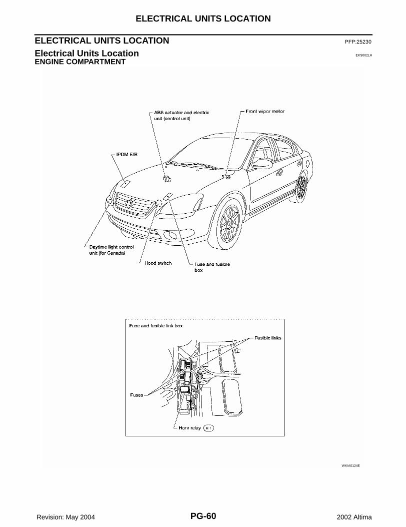
Electrical Units Location EKS002LH
ENGINE COMPARTMENT
WKIA0124E

ELECTRICAL UNITS LOCATION
PG-61
C
D
E
F
G
H
I
J
L
M
A
B
PG
Revision: May 2004 2002 Altima
PASSENGER COMPARTMENT
WKIA0125E

PG-62
ELECTRICAL UNITS LOCATION
Revision: May 2004 2002 Altima
WKIA0131E

ELECTRICAL UNITS LOCATION
PG-63
C
D
E
F
G
H
I
J
L
M
A
B
PG
Revision: May 2004 2002 Altima
Fuse EKS002LI
● If fuse is blown, be sure to eliminate cause of incident beforeinstalling new fuse.
● Use fuse of specified rating. Never use fuse of more than speci-fied rating.
● Do not partially install fuse; always insert it into fuse holder prop-erly.
● Remove fuse for “ELECTRICAL PARTS (BAT)” if vehicle is notused for a long period of time.
Fusible Link EKS002LJ
A melted fusible link can be detected either by visual inspection or byfeeling with finger tip. If its condition is questionable, use circuittester or test lamp.CAUTION:● If fusible link should melt, it is possible that critical circuit
(power supply or large current carrying circuit) is shorted.In such a case, carefully check and eliminate cause of inci-dent.
● Never wrap outside of fusible link with vinyl tape. Important:Never let fusible link touch any other wiring harness, vinylor rubber parts.
Circuit Breaker (Built Into BCM) EKS002LK
For example, when current is 30A, the circuit is broken within 8 to 20seconds.A circuit breaker is used for the following systems:● Power seat● Power windows● Power door locks● Remote keyless entry system
CEL083
WKIA0123E
SBF284E

PG-64
HARNESS CONNECTOR
Revision: May 2004 2002 Altima
HARNESS CONNECTOR PFP:B4341
Description EKS002LL
HARNESS CONNECTOR (TAB-LOCKING TYPE)● The tab-locking type connectors help prevent accidental looseness or disconnection.● The tab-locking type connectors are disconnected by pushing or lifting the locking tab(s). Refer to the
illustration below.Refer to the next page for description of the slide-locking type connector.CAUTION:Do not pull the harness or wires when disconnecting the connector.[Example]
SEL769DA

HARNESS CONNECTOR
PG-65
C
D
E
F
G
H
I
J
L
M
A
B
PG
Revision: May 2004 2002 Altima
HARNESS CONNECTOR (SLIDE-LOCKING TYPE)● A new style slide-locking type connector is used on certain systems and components, especially those
related to OBD.● The slide-locking type connectors help prevent incomplete locking and accidental looseness or discon-
nection.● The slide-locking type connectors are disconnected by pushing or pulling the slider. Refer to the illustra-
tion below.CAUTION:● Do not pull the harness or wires when disconnecting the connector.● Be careful not to damage the connector support bracket when disconnecting the connector.[Example]
AEL299C

PG-66
JOINT CONNECTOR (J/C)
Revision: May 2004 2002 Altima
JOINT CONNECTOR (J/C) PFP:B4341
Terminal Arrangement EKS002LM
WKIA0126E

ELECTRICAL UNITS
PG-67
C
D
E
F
G
H
I
J
L
M
A
B
PG
Revision: May 2004 2002 Altima
ELECTRICAL UNITS PFP:23710
Terminal Arrangement EKS002LN
WKIA0127E

PG-68
SMJ (SUPER MULTIPLE JUNCTION)
Revision: May 2004 2002 Altima
SMJ (SUPER MULTIPLE JUNCTION) PFP:B4341
Terminal Arrangement EKS002LO
WKIA0128E

STANDARDIZED RELAY
PG-69
C
D
E
F
G
H
I
J
L
M
A
B
PG
Revision: May 2004 2002 Altima
STANDARDIZED RELAY PFP:25230
Description EKS002LP
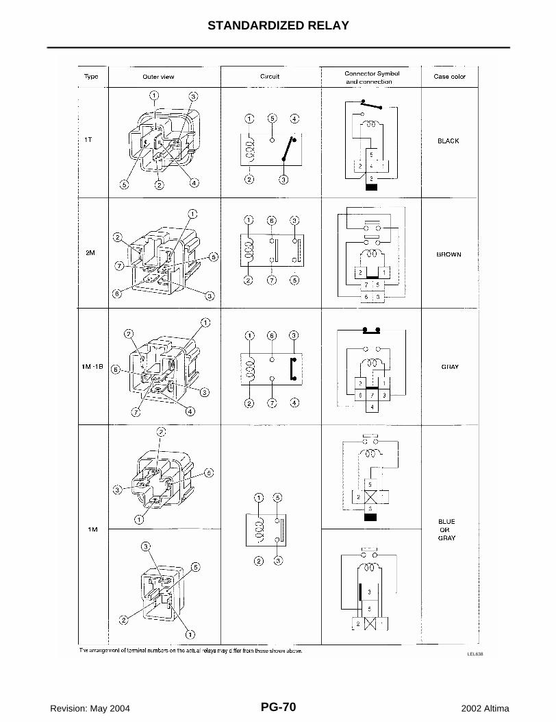
NORMAL OPEN, NORMAL CLOSED AND MIXED TYPE RELAYSRelays can mainly be divided into three types: normal open, normal closed and mixed type relays.
TYPE OF STANDARDIZED RELAYS
SEL881H
SEL882H
1M 1 Make 2M 2 Make
1T 1 Transfer 1M·1B 1 Make 1 Break
PG-70
STANDARDIZED RELAY
Revision: May 2004 2002 Altima
LEL638

FUSE BLOCK-JUNCTION BOX(J/B)
PG-71
C
D
E
F
G
H
I
J
L
M
A
B
PG
Revision: May 2004 2002 Altima
FUSE BLOCK-JUNCTION BOX(J/B) PFP:24350
Terminal Arrangement EKS002LQ
WKIA0129E

PG-72
FUSE AND FUSIBLE LINK BOX
Revision: May 2004 2002 Altima
FUSE AND FUSIBLE LINK BOX PFP:24381
Terminal Arrangement EKS002LR
WKIA0130E