
DC Circuits: Circuit Theorems · EENG223: CIRCUIT THEORY I A large complex circuits Simplify...
71
EENG223: CIRCUIT THEORY I DC Circuits: Circuit Theorems Hasan Demirel
Transcript of DC Circuits: Circuit Theorems · EENG223: CIRCUIT THEORY I A large complex circuits Simplify...

EENG223: CIRCUIT THEORY I
DC Circuits:
Circuit Theorems Hasan Demirel
EENG223: CIRCUIT THEORY I
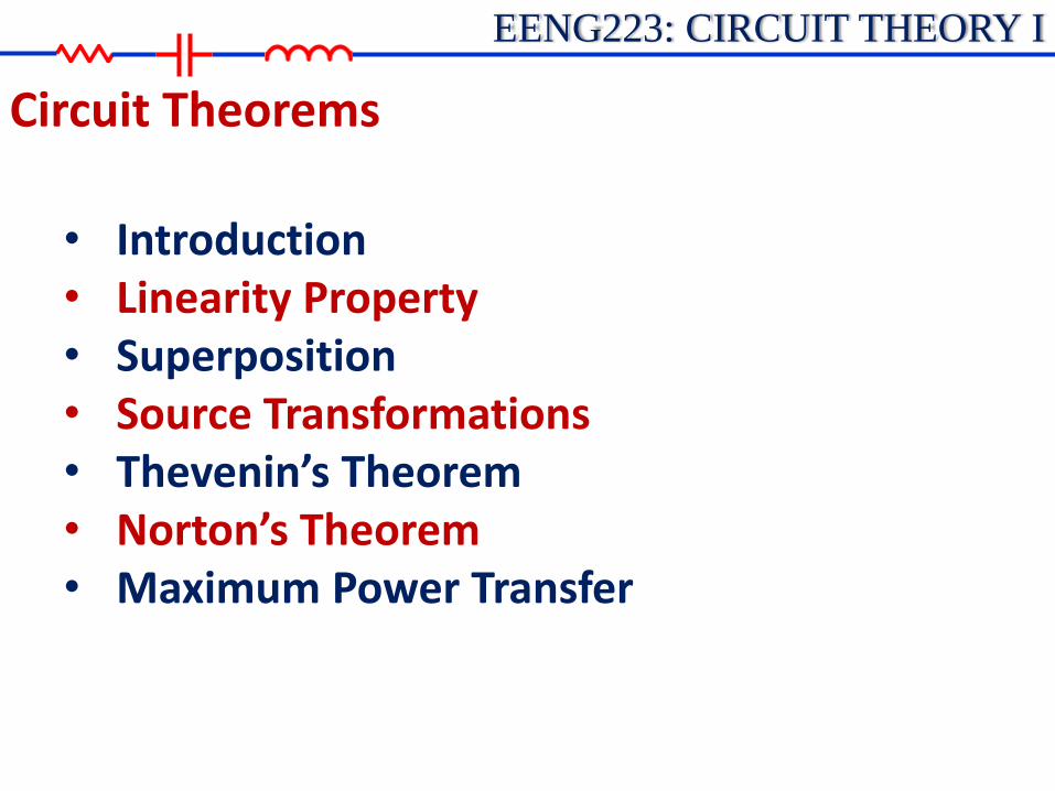
• Introduction • Linearity Property • Superposition • Source Transformations • Thevenin’s Theorem • Norton’s Theorem • Maximum Power Transfer
Circuit Theorems

EENG223: CIRCUIT THEORY I
A large complex circuits
Simplify circuit analysis
Circuit Theorems
‧Thevenin’s theorem ‧ Norton theorem ‧Circuit linearity ‧ Superposition ‧Source transformation ‧ Max. power transfer
Introduction

EENG223: CIRCUIT THEORY I
• Homogeneity property (Scaling)
• Additivity property
iRvi
kiRkvki
Rivi 222
Rivi 111
21212121 )( vvRiRiRiiii
Linearity Property

EENG223: CIRCUIT THEORY I
• A linear circuit is one whose output is linearly related (directly proportional) to its input.
v V0
I0
i
Linearity Property

EENG223: CIRCUIT THEORY I
• A linear circuit consist of :
• linear elements (i.e. R=5 W)
• linear dependent sources (i.e. vs=6Io V)
• independent sources (i.e. vs=12 V)
mA1mV5
A2.0V1
A2V10
iv
iv
iv
s
s
s
nonlinearR
vRip :
22
Linearity Property
EENG223: CIRCUIT THEORY I
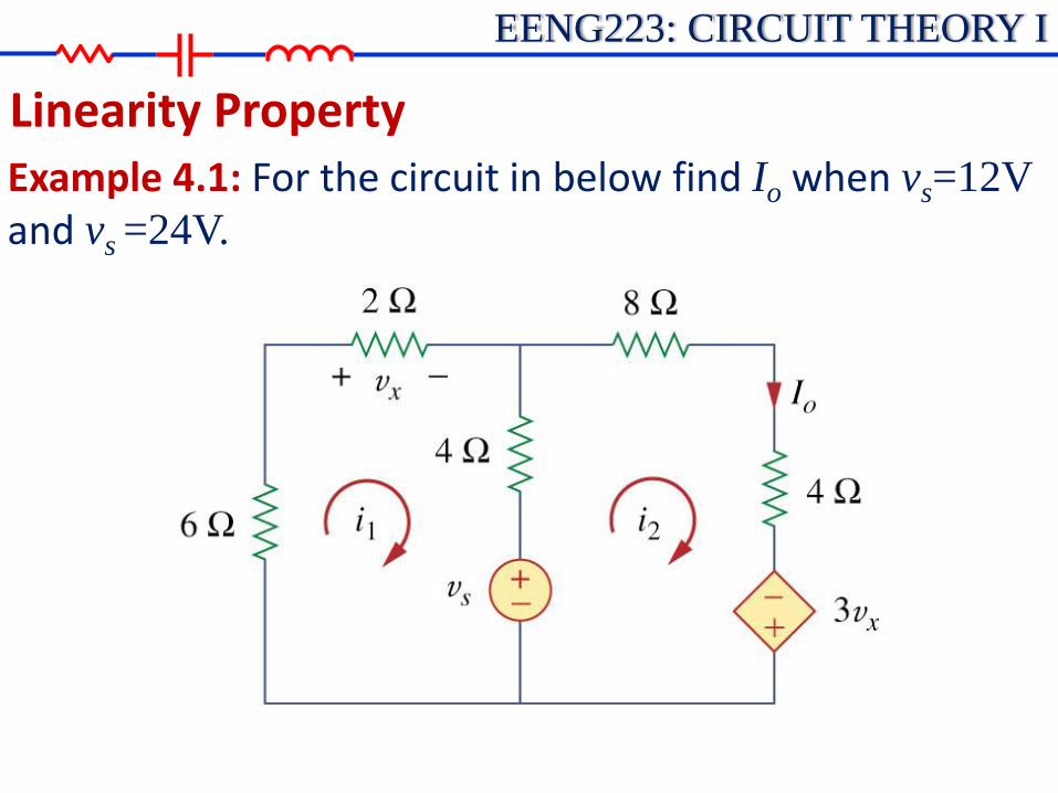
Linearity Property Example 4.1: For the circuit in below find Io when vs=12V
and vs =24V.

EENG223: CIRCUIT THEORY I
Linearity Property Example 4.1: For the circuit in below find Io when vs=12V
and vs =24V.
KVL
0412 21 svii
03164 21 sx vvii
12ivx
01610 21 svii
(1)
(2)
(3)
2121 60122 iiii
Using Eqs(1) and (3) we get
Eq(2) becomes

EENG223: CIRCUIT THEORY I
Linearity Property Example 4.1: For the circuit in below find Io when vs=12V
and vs =24V.
From Eq(1) we get:
A76
1220 iI
V12sv
A76
2420 iI
V24sv
when
when
Showing that when the source value is doubled, Io doubles.
76076 22
ss
vivi

EENG223: CIRCUIT THEORY I
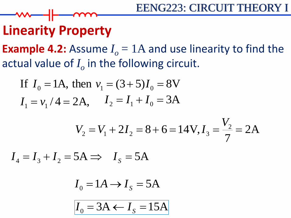
Linearity Property Example 4.2: Assume Io = 1A and use linearity to find the actual value of Io in the following circuit.
EENG223: CIRCUIT THEORY I
Linearity Property Example 4.2: Assume Io = 1A and use linearity to find the actual value of Io in the following circuit.
A,24/
V8)53(thenA,1If
11
010
vI
IvI
A3012 III
A27
,V14682 23212
VIIVV
A5234 III A5SI
A510 SIAI
A15A30 SII

EENG223: CIRCUIT THEORY I
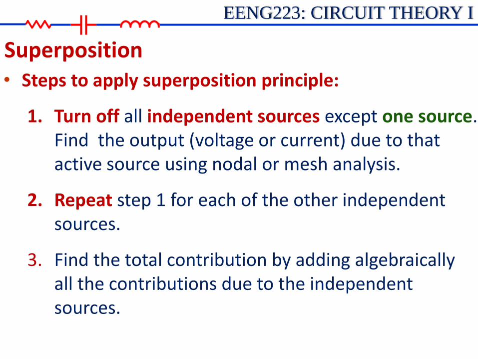
Superposition • The superposition principle states that the voltage
across (or current through) an element in a linear circuit is the algebraic sum of the voltages across (or currents through) that element due to each independent source acting alone.
• Turn off, kill, inactive source(s):
• independent voltage source: 0 V (short circuit)
• independent current source: 0 A (open circuit)
• Dependent sources are left intact.
EENG223: CIRCUIT THEORY I
Superposition • Steps to apply superposition principle:
1. Turn off all independent sources except one source. Find the output (voltage or current) due to that active source using nodal or mesh analysis.
2. Repeat step 1 for each of the other independent sources.
3. Find the total contribution by adding algebraically all the contributions due to the independent sources.

EENG223: CIRCUIT THEORY I
Superposition
• How to turn off independent sources:
Turn off voltages sources = short voltage sources; make it equal to zero voltage
Turn off current sources = open current sources; make it equal to zero current
• Superposition involves more work but simpler circuits.
• Superposition is not applicable to the effect on power.

EENG223: CIRCUIT THEORY I
Superposition
• Example 4.3: Use the superposition theorem to find v in the circuit below.

EENG223: CIRCUIT THEORY I
Superposition
• Example 4.3: Use the superposition theorem to find v in the circuit below.
Since there are two sources,
Let
Voltage division to get
Current division, to get
Hence
And we find
A2)3(84
83
i
V84 32 iv
V108221 vvv
21 vvv
V2)6(84
41
v

EENG223: CIRCUIT THEORY I
Superposition • Example 4.4: Find Io in the circuit below using
superposition.

EENG223: CIRCUIT THEORY I
Superposition • Example 4.4: Find Io in the circuit below using
superposition.
Turn off 20V voltage source:

EENG223: CIRCUIT THEORY I
Superposition • Example 4.4: Find Io in the circuit below using
superposition.
Turn off 4A current source:
EENG223: CIRCUIT THEORY I
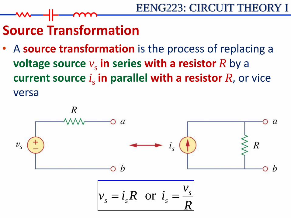
Source Transformation • A source transformation is the process of replacing a
voltage source vs in series with a resistor R by a current source is in parallel with a resistor R, or vice versa
R
viRiv ssss or

EENG223: CIRCUIT THEORY I
Source Transformation • Equivalent Circuits:
R
v
R
vi
viRv
s
s
i i
+ +
- -
v v
v
i
vs -is

EENG223: CIRCUIT THEORY I
Source Transformation • Source transformation: Important points
1. Arrow of the current source is directed toward the positive terminal of the voltage source.
2. Transformation is not possible when:
♦ ideal voltage source (R = 0)
♦ ideal current source (R=)

EENG223: CIRCUIT THEORY I
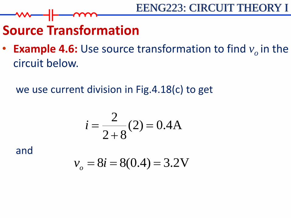
Source Transformation • Example 4.6: Use source transformation to find vo in the
circuit below.

EENG223: CIRCUIT THEORY I
Source Transformation • Example 4.6: Use source transformation to find vo in the
circuit below.
Fig.4.18
EENG223: CIRCUIT THEORY I
Source Transformation • Example 4.6: Use source transformation to find vo in the
circuit below.
we use current division in Fig.4.18(c) to get
and
A4.0)2(82
2
i
V2.3)4.0(88 ivo

EENG223: CIRCUIT THEORY I
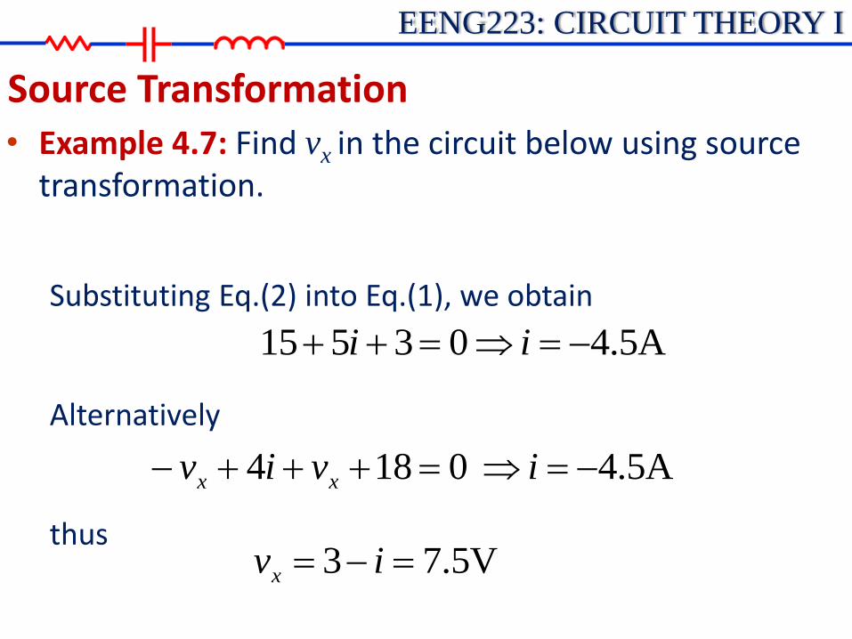
Source Transformation • Example 4.7: Find vx in the circuit below using source
transformation.

EENG223: CIRCUIT THEORY I
Source Transformation • Example 4.7: Find vx in the circuit below using source
transformation.
KVL around the loop in Fig (b)
01853 xvi
ivvi xx 3013
(1)
Appling KVL to the loop containing only the 3V voltage source, the 1W resistor, and vx yields:
(2)
EENG223: CIRCUIT THEORY I
Source Transformation • Example 4.7: Find vx in the circuit below using source
transformation.
Substituting Eq.(2) into Eq.(1), we obtain
Alternatively
thus
A5.403515 ii
A5.40184 iviv xx
V5.73 ivx
EENG223: CIRCUIT THEORY I
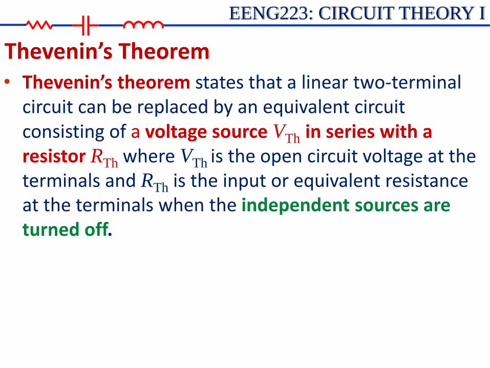
Thevenin’s Theorem • Thevenin’s theorem states that a linear two-terminal
circuit can be replaced by an equivalent circuit consisting of a voltage source VTh in series with a resistor RTh where VTh is the open circuit voltage at the terminals and RTh is the input or equivalent resistance at the terminals when the independent sources are turned off.

EENG223: CIRCUIT THEORY I
Thevenin’s Theorem • Property of Linear Circuits
i
v
v
i
Any two-terminal
Linear Circuits
+
-
Vth
Isc
Slope=1/RTh
EENG223: CIRCUIT THEORY I
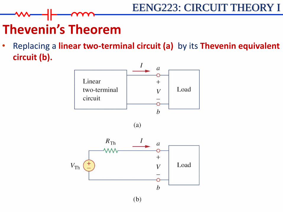
Thevenin’s Theorem • Replacing a linear two-terminal circuit (a) by its Thevenin equivalent
circuit (b).

EENG223: CIRCUIT THEORY I
Thevenin’s Theorem
• How to find Thevenin Voltage? Equivalent circuit: same voltage-current relation at the
terminals.
:Th ocvV ba atltagecircuit voopen

EENG223: CIRCUIT THEORY I
Thevenin’s Theorem
• How to find Thevenin Resistance?
:inTh RR b.a atcircuitdeadtheofresistanceinput
circuitedopenba
sourcestindependenalloffTurn

EENG223: CIRCUIT THEORY I
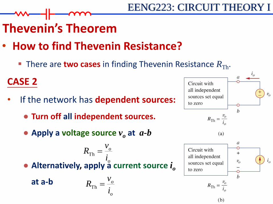
Thevenin’s Theorem
• How to find Thevenin Resistance?
There are two cases in finding Thevenin Resistance RTh.
CASE 1
• If the network has no dependent sources:
● Turn off all independent sources.
● RTh: can be obtained via simplification of either parallel or series connection seen from a-b
EENG223: CIRCUIT THEORY I
Thevenin’s Theorem
• How to find Thevenin Resistance?
There are two cases in finding Thevenin Resistance RTh.
CASE 2
• If the network has dependent sources:
● Turn off all independent sources.
● Apply a voltage source vo at a-b
● Alternatively, apply a current source io
at a-b
o
o
i
vR Th
o
o
i
vR Th

EENG223: CIRCUIT THEORY I
Thevenin’s Theorem
• How to find Thevenin Resistance?
The Thevenin resistance, RTh , may be negative, indicating that the circuit has ability providing (supplying) power.

EENG223: CIRCUIT THEORY I
Thevenin’s Theorem • After the Thevenin Equivalent is obtained, the simplified
circuit can be used to calculate IL and VL easily.
L
LRR
VI
Th
Th
Th
Th
VRR
RIRV
L
LLLL
Simplified circuit
Voltage divider
EENG223: CIRCUIT THEORY I
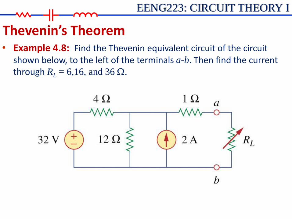
Thevenin’s Theorem • Example 4.8: Find the Thevenin equivalent circuit of the circuit
shown below, to the left of the terminals a-b. Then find the current through RL = 6,16, and 36 W.

EENG223: CIRCUIT THEORY I
Thevenin’s Theorem • Example 4.8: Find the Thevenin equivalent circuit of the circuit
shown below, to the left of the terminals a-b. Then find the current through RL = 6,16, and 36 W.
shortsourcevoltageV32:Th R
opensourcecurrentA2
W
4116
124112||4ThR
Find RTh:
EENG223: CIRCUIT THEORY I
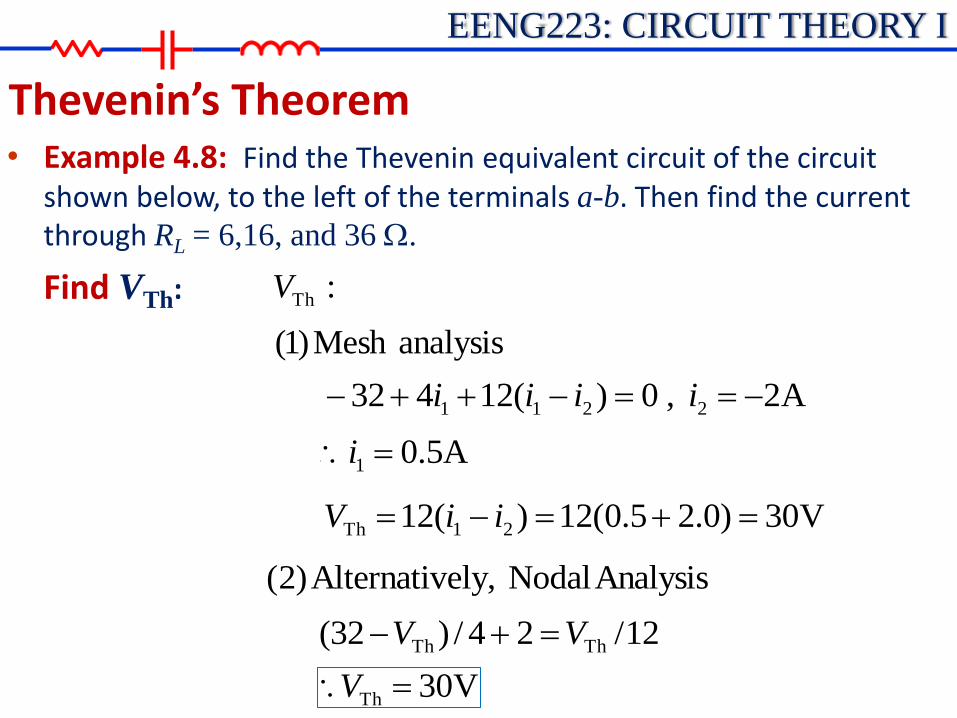
Thevenin’s Theorem • Example 4.8: Find the Thevenin equivalent circuit of the circuit
shown below, to the left of the terminals a-b. Then find the current through RL = 6,16, and 36 W.
Find VTh:
analysisMesh)1(
:ThV
A2,0)(12432 2211 iiii
A5.01 i
V30)0.25.0(12)(12 21Th iiV
AnalysisNodal ely,Alternativ)2(
12/24/)32( ThTh VV
V30Th V

EENG223: CIRCUIT THEORY I
Thevenin’s Theorem • Example 4.8: Find the Thevenin equivalent circuit of the circuit
shown below, to the left of the terminals a-b. Then find the current through RL = 6,16, and 36 W.
Find VTh: transformsource ely,Alternativ)3(
V3024396
122
4
32
THTHTH
THTH
VVV
VV
Thevenin Equivalent circuit:

EENG223: CIRCUIT THEORY I
Thevenin’s Theorem • Example 4.8: Find the Thevenin equivalent circuit of the circuit
shown below, to the left of the terminals a-b. Then find the current through RL = 6,16, and 36 W.
Calculate IL:
LL
LRRR
Vi
4
30
Th
Th
6LR A310/30 LI
16LR A5.120/30 LI
A75.040/30 LI36LR

EENG223: CIRCUIT THEORY I
Thevenin’s Theorem • Example 4.9: Find the Thevenin equivalent of the circuit below at
terminals a-b.

EENG223: CIRCUIT THEORY I
Thevenin’s Theorem • Example 4.9: Find the Thevenin equivalent of the circuit below at
terminals a-b.
• (independent + dependent sources case)
0sourcetindependen
intactsourcedependent
,V1ovoo
o
ii
vR
1Th
Find RTh: Use Fig (a):

EENG223: CIRCUIT THEORY I
Thevenin’s Theorem • Example 4.9: Find the Thevenin equivalent of the circuit below at
terminals a-b.
21 3ii
Find RTh: For Loop 1:
2121 or0)(22 iiviiv xx
2124But iiivx
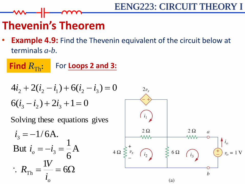
EENG223: CIRCUIT THEORY I
Thevenin’s Theorem • Example 4.9: Find the Thevenin equivalent of the circuit below at
terminals a-b.
Find RTh: For Loops 2 and 3:
0)(6)(24 32122 iiiii
012)(6 323 iii
gives equations theseSolving
.A6/13 i
A6
1But 3 iio
W 61
Th
oi
VR
EENG223: CIRCUIT THEORY I
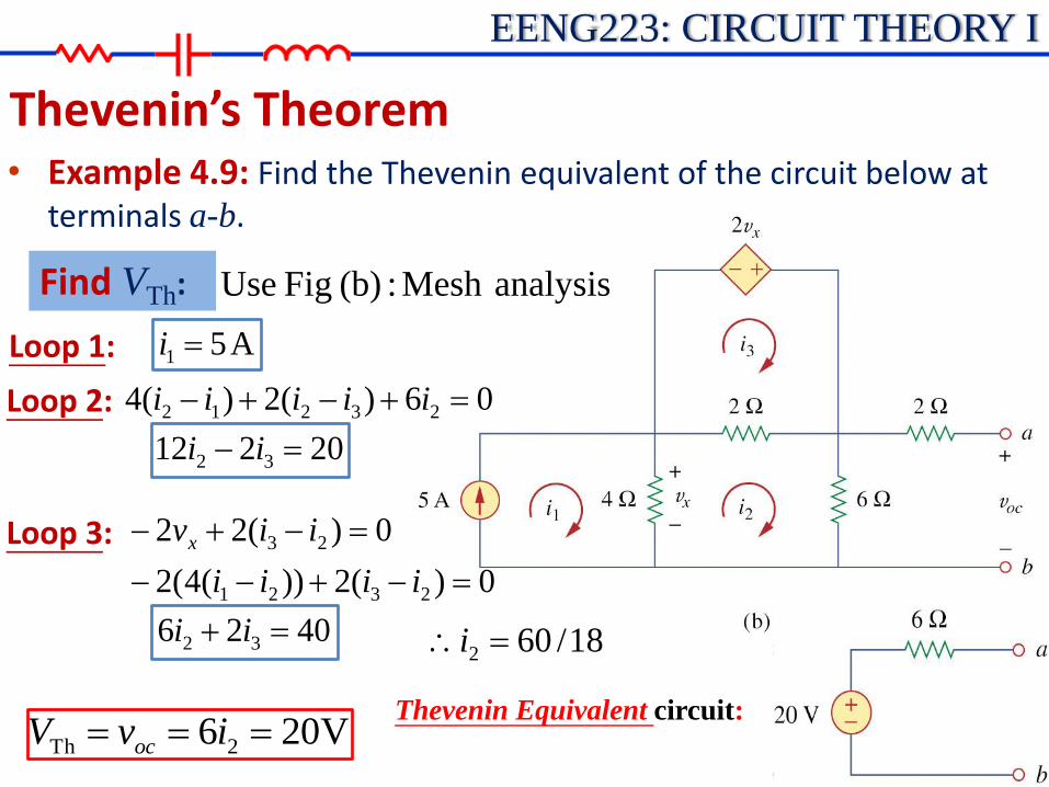
Thevenin’s Theorem • Example 4.9: Find the Thevenin equivalent of the circuit below at
terminals a-b.
Find VTh: analysisMesh :(b) Fig Use
18/602 i
V206 2Th ivV oc
Thevenin Equivalent circuit:
Loop 1:
Loop 2:
Loop 3:
A51 i
20212 32 ii
06)(2)(4 23212 iiiii
4026 32 ii
0)(2))(4(2
0)(22
2321
23
iiii
iivx

EENG223: CIRCUIT THEORY I
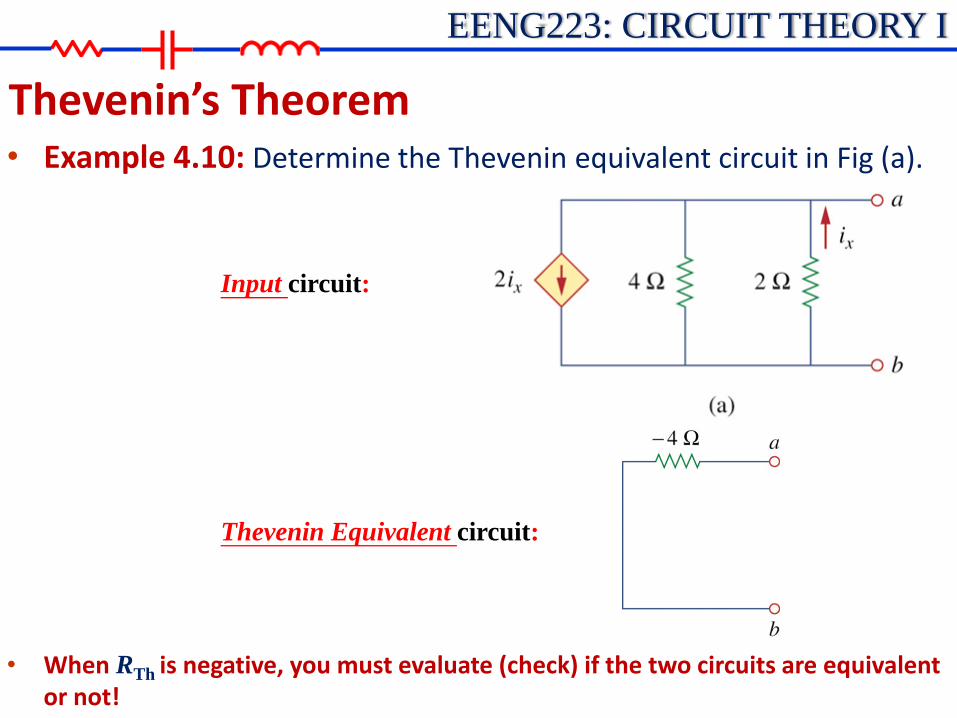
Thevenin’s Theorem • Example 4.10: Determine the Thevenin equivalent circuit in Fig (a).
0Th V
o
o
i
vR Th
:anaysisNodal
4/2 oxxo viii
Find RTh:
(dependent source only case)
Apply a current source io at a-b
Use Fig (b):
Find VTh:

EENG223: CIRCUIT THEORY I
Thevenin’s Theorem • Example 4.10: Determine the Thevenin equivalent circuit in Fig (a).
Find RTh:
22
0 oox
vvi
But
4424oooo
xo
vvvvii oo iv 4or
W 4Thus Th
o
o
i
vR power)(Supplying
Use Fig (b):
EENG223: CIRCUIT THEORY I
Thevenin’s Theorem • Example 4.10: Determine the Thevenin equivalent circuit in Fig (a).
Input circuit:
Thevenin Equivalent circuit:
• When RTh is negative, you must evaluate (check) if the two circuits are equivalent or not!

EENG223: CIRCUIT THEORY I
Thevenin’s Theorem • Example 4.10: Determine the Thevenin equivalent circuit in Fig (a).
Input circuit:
Thevenin Equivalent circuit:
Check with RL (9W) and voltage source (10V)
Check with RL (9W) and voltage source (10V)

EENG223: CIRCUIT THEORY I
Thevenin’s Theorem • Example 4.10: Determine the Thevenin equivalent circuit in Fig (a).
Input circuit:
Thevenin Equivalent circuit:
Check with RL (9W) and voltage source (10V)
Check with RL (9W) and voltage source (10V)
)1(3,062
,0)(248
2121
12211
iiii
iiiiiii xx
A2105
0109)(2
22
212
ii
iii
A2105
01094
ii
ii
Load current in both circuits are equal.
So the Thevenin Equivalent circuit is OK.
EENG223: CIRCUIT THEORY I
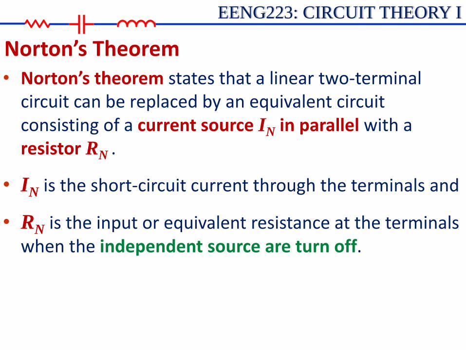
Norton’s Theorem • Norton’s theorem states that a linear two-terminal
circuit can be replaced by an equivalent circuit consisting of a current source IN in parallel with a resistor RN .
• IN is the short-circuit current through the terminals and
• RN is the input or equivalent resistance at the terminals when the independent source are turn off.

EENG223: CIRCUIT THEORY I
Norton’s Theorem
v
i
Vth
-IN
Slope=1/RN
• Property of Linear Circuits

EENG223: CIRCUIT THEORY I
Norton’s Theorem • How to find Norton Current
Thevenin and Norton resistances are equal:
ThRRN
Short circuit current from a to b gives the Norton current:
Th
Th
R
ViI scN

EENG223: CIRCUIT THEORY I
Norton’s Theorem • Thevenin or Norton equivalent circuit
The open circuit voltage voc across terminals a and b
The short circuit current isc at terminals a and b
The equivalent or input resistance Rin at terminals a and b when all independent source are turn off. V
N
N
ThTh
scN
ocTh
RI
VR
iI
vV

EENG223: CIRCUIT THEORY I
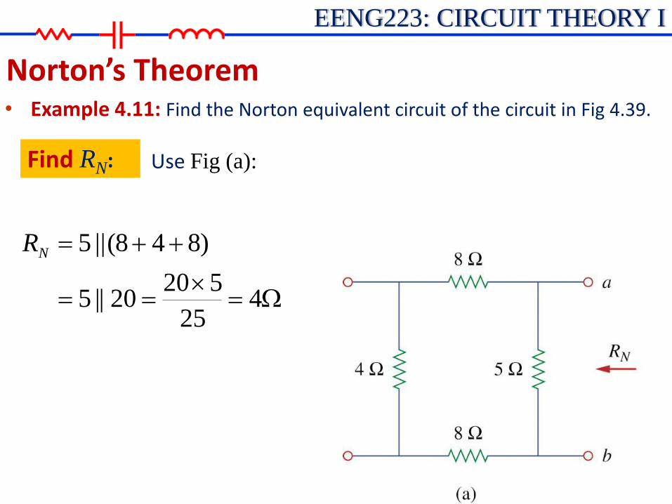
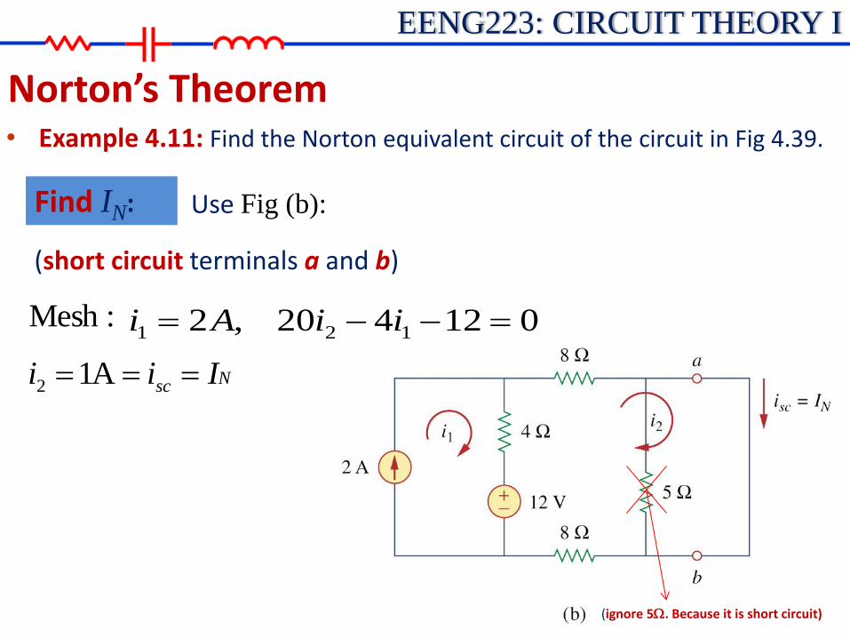
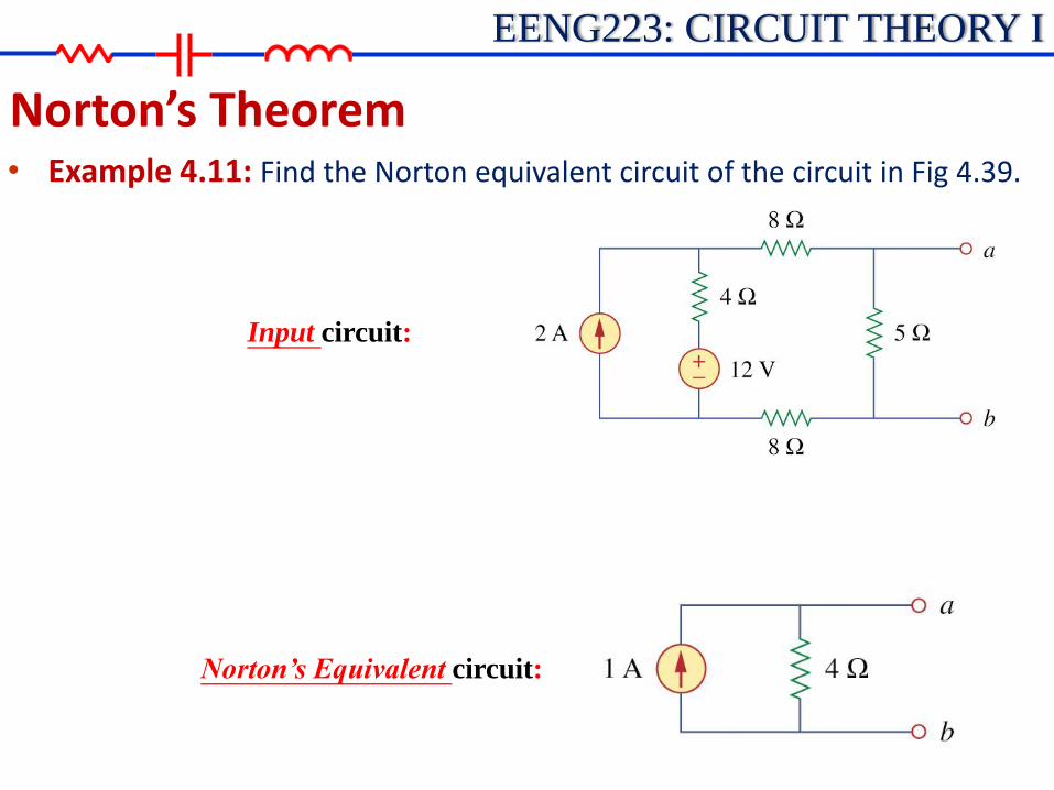
Norton’s Theorem • Example 4.11: Find the Norton equivalent circuit of the circuit in Fig 4.39.
EENG223: CIRCUIT THEORY I
Norton’s Theorem
Find RN: Use Fig (a):
W
425
52020||5
)848(||5NR
• Example 4.11: Find the Norton equivalent circuit of the circuit in Fig 4.39.
EENG223: CIRCUIT THEORY I
Norton’s Theorem
Find IN: Use Fig (b):
:Mesh
Nsc Iii A12
(short circuit terminals a and b)
012420,2 121 iiAi
(ignore 5W. Because it is short circuit)
• Example 4.11: Find the Norton equivalent circuit of the circuit in Fig 4.39.

EENG223: CIRCUIT THEORY I
Norton’s Theorem
Find IN: Use Fig (c): Alternative Method Th
ThN
R
VI
:ThV
:analysisMesh
012425,2 343 iiAi
A8.04 i
V45 4 iVv Thoc
(open circuit voltage accross terminals a and b)
,Hence
A14/4 Th
ThN
R
VI
• Example 4.11: Find the Norton equivalent circuit of the circuit in Fig 4.39.
EENG223: CIRCUIT THEORY I
Norton’s Theorem
Input circuit:
Norton’s Equivalent circuit:
• Example 4.11: Find the Norton equivalent circuit of the circuit in Fig 4.39.

EENG223: CIRCUIT THEORY I
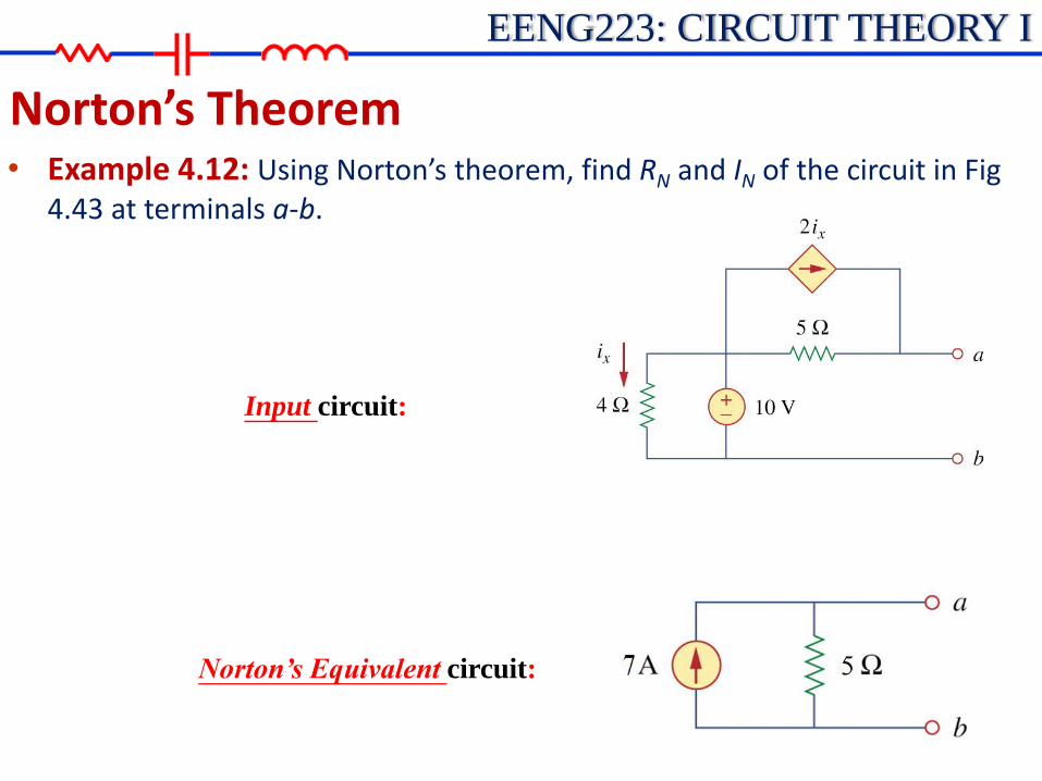
Norton’s Theorem • Example 4.12: Using Norton’s theorem, find RN and IN of the circuit in Fig
4.43 at terminals a-b.
EENG223: CIRCUIT THEORY I
Norton’s Theorem
shortedresistor4WParallel:2||||5 xo ivW
Hence,
W 52.0
1
o
oN
i
vR
Find RN: Use Fig (a):
A2.05
V1
5,A0 0
0 W
W
v
iix
• Example 4.12: Using Norton’s theorem, find RN and IN of the circuit in Fig 4.43 at terminals a-b.

EENG223: CIRCUIT THEORY I
Norton’s Theorem
Find IN:
xiv 2||5||10||4 WW Parallel:
.5A,24
010
xi
A72(2.5)5
102 xxsc iii
7A NI
• Example 4.12: Using Norton’s theorem, find RN and IN of the circuit in Fig 4.43 at terminals a-b.
EENG223: CIRCUIT THEORY I
Norton’s Theorem
Input circuit:
Norton’s Equivalent circuit:
• Example 4.12: Using Norton’s theorem, find RN and IN of the circuit in Fig 4.43 at terminals a-b.

EENG223: CIRCUIT THEORY I
Maximum Power Transfer • The Thevenin equivalent is useful in finding the
maximum power a linear circuit can deliver to a load.
LL RRR
VRip
2
LTH
TH2

EENG223: CIRCUIT THEORY I
Maximum Power Transfer • Maximum power is transferred to the load when the
load resistance equals the Thevenin resistance as seen from the load (RL = RTH).
LL RRR
VRip
2
LTH
TH2

EENG223: CIRCUIT THEORY I
Maximum Power Transfer • Pmax can be obtained when: 0
LdR
dp
THL
LTHLLTH
LTH
LLTHTH
LTH
LTHLLTHTH
LTH
LTHLLTHTH
L
RR
RRRRR
RR
RRRV
RR
RRRRRV
RR
RRRRRV
dR
dp
0)(0)2(
0)(
)2(
)(
)(2)(
0))((
)(2)(
3
2
4
22
22
22
TH
TH
R
Vp
4
2
max

EENG223: CIRCUIT THEORY I
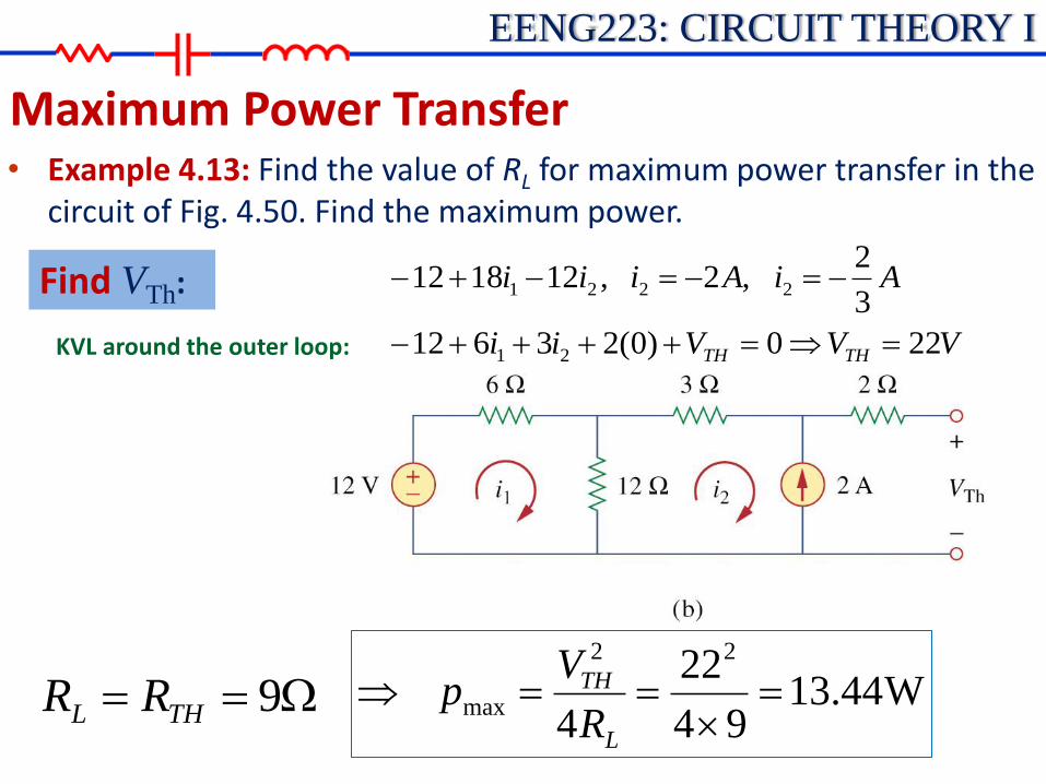
Maximum Power Transfer • Example 4.13: Find the value of RL for maximum power transfer in the
circuit of Fig. 4.50. Find the maximum power.

EENG223: CIRCUIT THEORY I
Maximum Power Transfer • Example 4.13: Find the value of RL for maximum power transfer in the
circuit of Fig. 4.50. Find the maximum power.
W
918
126512632THR
Find RTh:
EENG223: CIRCUIT THEORY I
Maximum Power Transfer • Example 4.13: Find the value of RL for maximum power transfer in the
circuit of Fig. 4.50. Find the maximum power.
VVVii
AiAiii
THTH 220)0(23612
3
2 ,2 ,121812
21
2221
Find VTh:
W 9THL RR W44.1394
22
4
22
max
L
TH
R
Vp
KVL around the outer loop:


![Circuit Theorems [相容模式] - National Chiao Tung University · 2012. 10. 5. · Circuit Theorems •Introduction •Linearity Property •Superposition •Source Transformation](https://static.fdocuments.in/doc/165x107/5ffa33782109f15b771b8b05/circuit-theorems-c-national-chiao-tung-2012-10-5-circuit-theorems.jpg)