SECTION ‘E’ Ceiling Systems. Contents. - B&B...
22
The Red Book ™ E1. Ceiling Systems. Contents. SUBJECT PAGE Introduction E2 Design Considerations E2 Installation E4 Components E4 System Specifications Floor/Ceiling Systems E6 Roof/Ceiling Systems E12 Floor or Ceiling Systems - Fire Rated from Above E16 Ceiling Systems - Fire Rated from Above and/or Below E17 Panel Ceiling Systems E18 System Installation Details E19 SECTION ‘E’
Transcript of SECTION ‘E’ Ceiling Systems. Contents. - B&B...

The Red Book™E1.
Ceiling Systems.
Contents.SUBJECT PAGE
Introduction E2
Design Considerations E2
Installation E4
Components E4
System Specifications
Floor/Ceiling Systems E6
Roof/Ceiling Systems E12
Floor or Ceiling Systems - Fire Rated from Above E16
Ceiling Systems - Fire Rated from Above and/or Below E17
Panel Ceiling Systems E18
System Installation Details E19
SECTION ‘E’

E2. The Red Book™
Introduction.CSR Gyprock and Fibre Cement (GFC) has
developed a wide range of floor/ceiling androof/ceiling systems to meet specific fire and acousticrequirements. The systems include ratings for soundtransmission, sound impact and sound absorption, andfor fire resistance up to FRL 120/120/120.
Generally, the fire resistance of floor androof/ceiling systems is assessed from below, inaccordance with the standard fire test of AS1530.4.This is the requirement of the BCA where lightweightconstruction is used for compartmentation andseparation. Some elements such as fire-isolatedpassageways are required to have an FRL when testedfrom outside. A number of ceiling systems are availablethat offer fire resistance from above to meet thisrequirement.
CSR GFC ceiling systems use var ious fixingtechniques for the attachment of linings. Theseinclude:
a) Direct fixing to timber and steel joists or trussbottom chords.
b) Screw fixing to steel furring channels that areattached to joists.
c) Screw fixing to resilient or resiliently mountedfurring channels.
d) Screw fixing to suspended concealed metal grid.
e) Lay-in panels in suspended exposed metal grid.
DesignConsiderations.
STRUCTURAL.
All floor, roof and ceiling framing must be designedfor the applied loads. Guidance for the selection ofRondo suspension and grid components is given inbrochure NºGYP570 ‘Gyprock® Ceiling SystemsInstallation Guide’. For other elements, refer to theappropriate design standards or handbooks, or contactthe manufacturer for design information.
CSR GFC recommends a minimum designpressure of 0.25kPa (downward) for the ceilingframing. Other wind pressures may be applicable; thedesigner should refer to AS/NZS1170.
Wind loads on external ceilings can be similar tothose on adjacent walls. Pressures can be positive ornegative and the lining, grid and structure should bedesigned to resist the loads. Internal suspension
components, even with down struts, may not besuitable.
The maximum spacing of ceiling framing is600mm. Closer spacing may be required for somelining materials or for design loads greater than 0.5kPa.
CSR GFC Ceiling systems have been designed fortimber or steel framing as noted in the systemspecification. Timber framing shall be solid timber orengineered floor joist such as LVL Glulam, plywebjoists, or trusses made from solid timber framing mustbe designed in accordance with AS1720.1. or AS1684
Steel framing for direct fixing of linings shall havebase metal thickness (BMT) 0.5 - 1.6mm. Framingmay be trusses, top hats, C sections, furring channels,or similar members. in all cases they should bedesigned in accordance with AS4600.
For steel components in external environments, inheavy industr ial areas or coastal areas, additionalcoatings may be required. Refer to AS/NZS2785 forguidance
Direct-Fix Framing Systems.
Ceiling linings may be fixed directly to primarytimber or steel framing, or to secondary members suchas furring channels and battens.
Timber members to which plasterboard will befixed must comply with AS1684 ‘Residential Timber-Framed Construction’, or be designed in accordancewith AS1720.1 ‘Timber Structures: Design Methods’.
Steel framing to which plasterboard will be fixedmust comply with AS/NZS4600, ‘Cold Formed SteelStructures’.
Suspended Ceiling Systems.
Ceiling suspension systems must be designed toAS/NZS2785 ‘Suspended Ceilings – Design andInstallation’. Ceilings in this manual are not trafficable.Trafficable systems shall be designed in accordancewith AS1657 ‘Fixed Platforms, Walkways, Stairwaysand Ladders’.
Ceilings Rated from Above.
Ceiling systems with plasterboard linings on top ofjoists are not trafficable or intended to be used forstorage. The joists should be designed for all imposedloads including construction loads where fixing ofsheets is required from above. Appropriate barriers andsignage should be installed to prevent access.
FIRE PERFORMANCE.
Gyprock® fire rated ceiling systems. have beendesigned with fire protection that protects the framing.

The Red Book™E3.
This means that no consideration of steel or timberframing design need be given for the fire rating.
To protect structural beams that are entirely withinthe ceiling space, the structural adequacy componentof the ceiling system FRL must be at least equivalentto that required by the structural member. Forexample, a ceiling system with FRL 90/90/90 providesFRL 90/-/- for a steel beam within the ceiling.Systems are available for beams that are not entirelyenclosed.
Framing and Lining.
Plasterboard must be screw fixed only, adhesive isnot permitted. Joints in the outer layer of all systemsmust be set with Gyprock® paper tape. As a minimum,a single coat finish may be used.
For general installation information refer to FIG.E3 to F9. Detailed fixing information is provided inbrochures: Gyprock® Ceiling Systems InstallationGuide NºGYP570, CSR Gyprock Shaft SystemsNºGYP546, CSR Fibre Cement Ceiling SystemsNºFC129, CSR Fibre Cement ExpressWall FacadeSystem NºFC126 and CSR Hebel SoundFloor DesignGuide, NºHBL751-SFS.
Ceiling systems are generally shown in a horizontalorientation. The system FRL will not be reduced ifceilings are built on a rake. The support framing,including lateral bracing, must be designed consideringthe slope of the ceiling.
Alternative support framing members may be usedwhere timber joists are shown without reducing thesystem FRL. These members include, but are notlimited to, steel, composite steel/timber joists,laminated timber joists, and trussed or plywood webjoists.
System specifications for minimum cavity depthsand floor surface finishes relate to acousticperformance only.
Caulking.
To attain the specified FRL, all perimeter gaps andpenetrations must be carefully and completely filledwith appropriate caulking mater ial. In fire ratedsystems, to attain the stated FRL use CSR GyprockFire Mastic or other tested fire rated material ofequivalent or better performance. Details for firesealing of penetrations is given in Section ‘Z’.
Vermiculite plaster is not to be used as a generalpurpose fire rated caulking. Its use is specified in somewall/ceiling junctions; refer to Gyprock® CeilingSystems Installation Guide NºGYP570. Vermiculiteplaster has no capacity to accommodate buildingmovement.
ACOUSTIC PERFORMANCE.
Sound Transmission.
Sound flanking, the effectiveness of workmanshipand caulking, the presence and treatment ofpenetrations, and the inclusion of structural elementsand br idging items, may affect the acousticperformance of ceiling systems. Refer to Section ‘A’for detailed information.
Alternative structural framing systems includingsteel, and composite steel/timber joists, laminatedtimber joists, and trussed or plywood web joists may beused without reducing the system rating. The stated orimplied minimum cavity depth must also bemaintained.
For effective control of sound in the flanking pathof a floor or roof space, acoustically rated walls shouldcontinue to the underside of the floor or roof above.Alternatively, select a detail from section ‘Z’ equivalentto the required Rw or Rw + Ctr performance of thewall.
In non-fire rated systems, to attain the stated soundtransmission performance use CSR Gyprock® WetArea Acrylic Sealant, Gyprock® Fire Mastic or othertested acoustic rated material of equivalent or betterperformance.
Sound impact performance is stated as Ln,w + CI.Note that a lower value of Ln,w + CI has a higherimpact performance.
Floors finished with carpet and underlay achievebetter impact performance than those with hardsurfaces such as floorboards and tiles. If carpet issubsequently removed (from a system that uses it in itsperformance value), the floor may no longer meet theBCA impact requirements.
Sound Absorption.
Gyprock® Perforated Plasterboard, Ecophon andCelotex ceiling products, have sound absorptionqualities. These products may be used to influence thereverberation time of a room in order to improve thesound quality.
Product performance is expressed as NRC inaccordance with ASTM C423.This is calculated as theaverage of four frequencies in the range 250 – 2000Hz.Sound absorption values vary from 0 (total reflection)and 1.00 (total absorption) NRC values can be foundin system CSR 890

E4. The Red Book™
InstallationFor detailed information on junctions with walls,
access hatches, light fixtures, control joints andpenetrations, refer to Section ‘Z’ of this manual.
Plasterboard & Fibre Cement Fixing.
Ceilings may be built to achieve a particular ‘Levelof Finish’ as defined in AS/NZS2589.1. The Level ofFinish specified can have requirements for framealignment, jointing and back blocking methods.
Lining sheets must be installed with the long edgeat right angles to the direction of the framing to whichthey are fixed. Refer to FIG. E3 to E9 for generalfixing information using fastener and fastener/adhesivefixing methods. Detailed fixing information isprovided in Gyprock® Residential Installation Guide,NºGYP547, CSR Fibre Cement Ceiling SystemsNºFC129 and Gyprock® Ceiling Systems InstallationGuide, NºGYP570.
Jointing.
Refer to the Gyprock® Residential InstallationGuide, NºGYP547 for detailed jointing and finishingof ceilings lined with plasterboard. In multi-layersystems, jointing and finishing is required on the visibleouter layer only.
Expressed joints are recommended for ceilings linedwith CSR Fibre Cement products. Refer to CSRFibre Cement Ceiling Systems NºFC129 for moreinformation.
Control Joints.
Control joints are used to reduce the possibility ofcracks forming from structural movement, thermal andmoisture movement and the like. Locations for jointsshould be chosen by the designer with regard tobuilding shape, structural breaks, changes of substrate,and joint appearance.
Ceiling systems with plasterboard linings must havecontrol joints at 12m maximum spacing in bothdirections. Ceilings lined with CSR Fibre CementWallboard should have joints at 3.6m in most cases. Foradditional information, refer to CSR Fibre CementCeiling Systems NºFC129.
Components.LINING & FIXING MATERIALS
Refer to Section ‘A’ of this manual for detailedinformation on Gyprock® plasterboard products, CSRFibre Cement products, adhesive and fastenerspecifications.
Details of the performance and range of Ecophonand Celotex acoustic ceiling panels can be found inspecific product manuals. Please contact CSR Gyprockfor more information.
Steel Grid & Suspension Components.
CSR Gyprock and Fibre Cement recommends steelcomponents manufactured by Rondo BuildingServices Pty Ltd. Additional information on the steelcomponents can be obtained from the Rondo BuildingServices Pty Ltd, telephone 1300 367 663.
Top Cross Rail
Resilient Mount to Top Cross Rail Clip
Gyprock Resilient Mount
Furring Channel
Gyprock Screw
40m
m (
Nº1
29)
28m
m (
Nº3
08)
20m
m
24mm4.5mm
Furring ChannelNº129 or Nº308
GyprockResilient Mount
GYPROCK Plasterboard
GYPROCK RESILIENT MOUNT.
Other.
Sarking with mass at least 350g/m2 is specified insome roof/ceiling systems to achieve the acousticvalue. Suitable products are Bradford Thermofoil™ 733and Thermotuff™ SS.

The Red Book™E5.
1200
mm
(no
min
al)
1050
mm
Overall 3600mm (nominal)
450mm
75mmnom.
150mm450mm
FIG E2. GYPROCK® PERFORATED PLASTERBOARD SHEET.
8.2% OPEN AREA
1200
mm
(no
min
al)
3600mm (nominal)
FIG E1. PERFORATION PATTERN.
TABLE E1.MAXIMUM SPAN OF PLASTERBOARD IN CEILING APPLICATIONS.
GYPROCK Plasterboard Maximum Spacing of Framing MembersGeneral Applications Areas of High Humidity
Thickness (mm) (mm)6.5mm Flexible Plasterboard used in two layers 350 NA 10mm GYPROCK Plasterboard CD6mm CSR Fibre Cement Wallboard 450 NA10mm SOUNDCHEK, AQUACHEK, IMPACTCHEK, SUPACEIL, FLAMECHEK MR 600 45013mm plasterboard all types except Perforated9mm CSR Fibre Cement Wallboard 600 45013mm Perforated Sheet 600 NA16mm FYRCHEK 600 450NA = Not Applicable

E6. The Red Book™
– / – / –(a) Nil 38/–
(b) 105 Comfortseal™ R2.0 GW 42/–
(c) 75 Soundscreen™ R2.0 RW 42/–
CSR 804• 2 x 10mm GYPROCK
SOUNDCHEKplasterboard.
– / – / –(a) Nil 34/–
(b) 105 Comfortseal™ R2.0 GW 37/–
(c) 75 Soundscreen™ R2.0 RW 37/–
CSR 803 • 1 x GYPROCKSUPACEIL plasterboard.
– / – / –(a) Nil 38/–
(b) 105 Comfortseal™ R2.0 GW 42/–
(c) 75 Soundscreen™ R2.0 RW 42/–
CSR 802 • 2 x 13mm GYPROCKPlasterboard CD.
– / – / –(a) Nil 35/–
(b) 105 Comfortseal™ R2.0 GW 38/–
(c) 75 Soundscreen™ R2.0 RW 38/–
CSR 801 • 1 x 13mm GYPROCKPlasterboard CD.
– / – / –(a) Nil 27/–
(b) 105 Comfortseal™ R2.0 GW –
(c) 75 Soundscreen™ R2.0 RW –
CSR 800 • Nil
ACOUSTICOPINION
PKA-A029
FRLReport/Opinion
SYSTEM Nº
CEILING LININGS
SYSTEM SPECIFICATION TYPICAL LAYOUT
• 100 x 20mm Tongue & Grooved Cypress Pine Flooring.
• Timber or steel Joists at 450mm centres.
• Minimum 190mm cavity depth.
• Cavity insulation as per system table.
• Ceiling lining as per system table, direct fixed to framing.
CAVITY INFILL (Refer to Section A) Rw / Rw+Ctr
Floor/Ceiling Systems.

The Red Book™E7.
120/120/120+RISF 60 minutes
FCO 1373
(a) Nil 41/35 82/79 65/62
(b) 105 Comfortseal™ R2.0 GW 45/39 77/74 60/57
(c) 75 Soundscreen™ R2.0 RW 44/37 77/74 60/57
CSR 808 • 3 x 16mm GYPROCKFYRCHEK plasterboard.
90/90/90+RISF 60 minutes
FCO 1373
(a) Nil 40/33 83/80 66/63
(b) 105 Comfortseal™ R2.0 GW 44/37 78/75 61/58
(c) 75 Soundscreen™ R2.0 RW 43/35 78/75 61/58
CSR 807 • 2 x 16mm GYPROCKFYRCHEK plasterboard.
60/60/60+RISF 60 minutes
FCO 964
(a) Nil 40/33 83/80 68/65
(b) 105 Comfortseal™ R2.0 GW 44/37 78/75 63/60
(c) 75 Soundscreen™ R2.0 RW 43/39 78/75 63/60
CSR 809
• 1 x 13mm GYPROCKFYRCHEK (against frame).
•1 x 16mm GYPROCKFYRCHEK plasterboard.
60/60/60+RISF 30 minutes
FCO 1373
(a) Nil 38/30 83/80 68/65
(b) 105 Comfortseal™ R2.0 GW 42/34 78/75 63/60
(c) 75 Soundscreen™ R2.0 RW 41/32 78/75 63/60
CSR 806 • 2 x 13mm GYPROCKFYRCHEK plasterboard.
30/30/30FCO 1373
(a) Nil 35/27 85/82 70/67
(b) 105 Comfortseal™ R2.0 GW 39/31 80/77 65/62
(c) 75 Soundscreen™ R2.0 RW 38/29 80/77 65/62
CSR 805 • 1 x 13mm GYPROCKFYRCHEK plasterboard.
ACOUSTICOPINION
PKA-A029
FRLReport/Opinion
SYSTEM Nº
CEILING LININGS
SYSTEM SPECIFICATION TYPICAL LAYOUT
• Floor finished bare or with carpet and underlay, as persystem table.
• 1 x 19mm or 22mm particleboard, or timber flooring ofat least 15kg/m2.
• Timber or steel joists at 600mm maximum centres.
• Minimum 190mm cavity depth.
• Cavity insulation as per system table.
• Ceiling lining as per system table, direct fixed to framing.
Bare Carpet + CAVITY INFILL (Refer to Section A) Floor Underlay
Rw / Rw+Ctr Ln,w+CI/Ln,w Ln,w+CI/Ln,w
Floor/Ceiling Systems. RISF = Resistance to Incipient Spread of Fire

E8. The Red Book™
120/120/120+RISF 60 minutes
FCO 1373
(a) Nil 47/41 73/70 53/50
(b) 105 Comfortseal™ R2.0 GW 55/49 68/65 48/45
(c) 75 Soundscreen™ R2.0 RW 55/49 68/65 48/45
CSR 818 • 3 x 16mm GYPROCKFYRCHEK plasterboard.
90/90/90+RISF 60 minutes
FCO 1373
(a) Nil 46/37 75/72 60/57
(b) 105 Comfortseal™ R2.0 GW 54/47 73/70 55/52
(c) 75 Soundscreen™ R2.0 RW 54/47 73/70 55/52
CSR 817 • 2 x 16mm GYPROCKFYRCHEK plasterboard.
60/60/60+RISF 60 minutes
FCO 964
(a) Nil 46/39 75/72 60/57
(b) 105 Comfortseal™ R2.0 GW 54/47 73/70 55/52
(c) 75 Soundscreen™ R2.0 RW 54/47 73/70 55/52
CSR 819
• 1 x 13mm GYPROCKFYRCHEK (against frame).
• 1 x 16mm GYPROCKFYRCHEK plasterboard.
60/60/60+RISF 30 minutes
FCO 1373
(a) Nil 43/35 78/75 63/60
(b) 105 Comfortseal™ R2.0 GW 51/43 76/73 58/55
(c) 75 Soundscreen™ R2.0 RW 51/43 76/73 58/55
CSR 816 • 1 x 16mm GYPROCKFYRCHEK plasterboard.
60/60/60+RISF 30 minutes
FCO 1373
(a) Nil 45/30 76/73 61/58
(b) 105 Comfortseal™ R2.0 GW 53/46 74/71 56/53
(c) 75 Soundscreen™ R2.0 RW 53/46 74/71 56/53
CSR 814 • 2 x 13mm GYPROCKFYRCHEK plasterboard.
30/30/30FCO 1373
(a) Nil 41/32 79/76 64/61
(b) 105 Comfortseal™ R2.0 GW 46/37 77/74 59/56
(c) 75 Soundscreen™ R2.0 RW 46/37 77/74 59/56
CSR 815 • 1 x 13mm GYPROCKFYRCHEK plasterboard.
– / – / –(a) Nil 41/32 79/76 64/61
(b) 105 Comfortseal™ R2.0 GW 46/37 77/74 59/56
(c) 75 Soundscreen™ R2.0 RW 46/37 77/74 59/56
CSR 813 • 1 x 9mm CSR FibreCement Wallboard.
– / – / –(a) Nil 39/30 80/77 65/62
(b) 105 Comfortseal™ R2.0 GW 44/35 78/75 60/57
(c) 75 Soundscreen™ R2.0 RW 44/35 78/75 60/57
CSR 812• 1 x 6mm CSR Fibre
Cement Wallboard.(Furring at 450mm max.centres)
– / – / –(a) Nil 39/30 80/77 65/62
(b) 105 Comfortseal™ R2.0 GW 44/35 78/75 60/57
(c) 75 Soundscreen™ R2.0 RW 44/35 78/75 60/57
CSR 811 • 1 x 13mm GYPROCKPlasterboard CD.
– / – / –(a) Nil 38/29 81/78 66/63
(b) 105 Comfortseal™ R2.0 GW 43/34 79/76 61/58
(c) 75 Soundscreen™ R2.0 RW 43/34 79/76 61/58
CSR 810 • 1 x 10mm GYPROCKSUPACEIL plasterboard.
ACOUSTICOPINION
PKA-A029
FRLReport/Opinion
SYSTEM Nº
CEILING LININGS
SYSTEM SPECIFICATION TYPICAL LAYOUT
• Floor finished bare or with carpet and underlay, as persystem table.
• 1 x 19mm or 22mm particleboard, or timber flooring ofat least 15kg/m2.
• Timber or steel joists at 600mm maximum centres.
• Minimum 205mm cavity depth.
• RONDO Furring Channel at 600mm maximum centres,(except where noted).
• Cavity insulation as per system table.
• Ceiling lining as per system table, fixed to furring channel.
Bare Carpet + CAVITY INFILL (Refer to Section A) Floor Underlay
Rw / Rw+Ctr Ln,w+CI/Ln,w Ln,w+CI/Ln,w
Floor/Ceiling Systems. RISF = Resistance to Incipient Spread of Fire
The Red Book™E9.
90/90/90+RISF 60 minutes
FCO 1373
(a) Nil 51/44 67/70 48/51
(b) 105 Comfortseal™ R2.0 GW 57/50 62/65 42/45
(c) 75 Soundscreen™ R2.0 RW 56/48 62/65 42/45
CSR 827 • 2 x 16mm GYPROCKFYRCHEK plasterboard.
60/60/60+RISF 30 minutes
FCO 1373
(a) Nil 51/44 78/71 49/52
(b) 105 Comfortseal™ R2.0 GW 57/50 63/66 43/46
(c) 75 Soundscreen™ R2.0 RW 56/48 63/66 43/46
CSR 822 • 2 x 13mm GYPROCKFYRCHEK plasterboard.
60/60/60+RISF 60 minutes
FCO 964
(a) Nil 50/42 67/70 48/51
(b) 105 Comfortseal™ R2.0 GW 57/50 62/65 42/45
(c) 75 Soundscreen™ R2.0 RW 56/48 62/65 42/45
CSR 829
• 1 x 13mm GYPROCKFYRCHEK (against frame).
• 1 x 16mm GYPROCKFYRCHEK plasterboard.
60/60/60+RISF 30 minutes
FCO 1373
(a) Nil 48/40 71/74 52/55
(b) 105 Comfortseal™ R2.0 GW 54/46 62/65 44/47
(c) 75 Soundscreen™ R2.0 RW 53/44 62/65 44/47
CSR 826 • 1 x 16mm GYPROCKFYRCHEK plasterboard.
30/30/30FCO 1373
(a) Nil 46/39 72/75 53/56
(b) 105 Comfortseal™ R2.0 GW 52/44 63/66 45/48
(c) 75 Soundscreen™ R2.0 RW 51/42 63/66 45/48
CSR 825 • 1 x 13mm GYPROCKFYRCHEK plasterboard.
– / – / –(a) Nil 49/41 69/72 50/53
(b) 105 Comfortseal™ R2.0 GW 57/49 64/67 44/47
(c) 75 Soundscreen™ R2.0 RW 56/47 64/67 44/47
CSR 824• 2 x 10mm GYPROCK
SOUNDCHEKplasterboard.
– / – / –(a) Nil 45/37 73/76 54/57
(b) 105 Comfortseal™ R2.0 GW 53/45 64/67 46/49
(c) 75 Soundscreen™ R2.0 RW 52/43 64/67 46/49
CSR 823• 1 x 10mm GYPROCK
SOUNDCHEKplasterboard.
– / – / –(a) Nil 45/36 73/76 55/58
(b) 105 Comfortseal™ R2.0 GW 53/44 64/67 47/50
(c) 75 Soundscreen™ R2.0 RW 52/42 64/67 47/50
CSR 821 • 1 x 13mm GYPROCKPlasterboard CD.
ACOUSTICOPINION
PKA-A029
FRLReport/Opinion
SYSTEM Nº
CEILING LININGS
SYSTEM SPECIFICATION TYPICAL LAYOUT
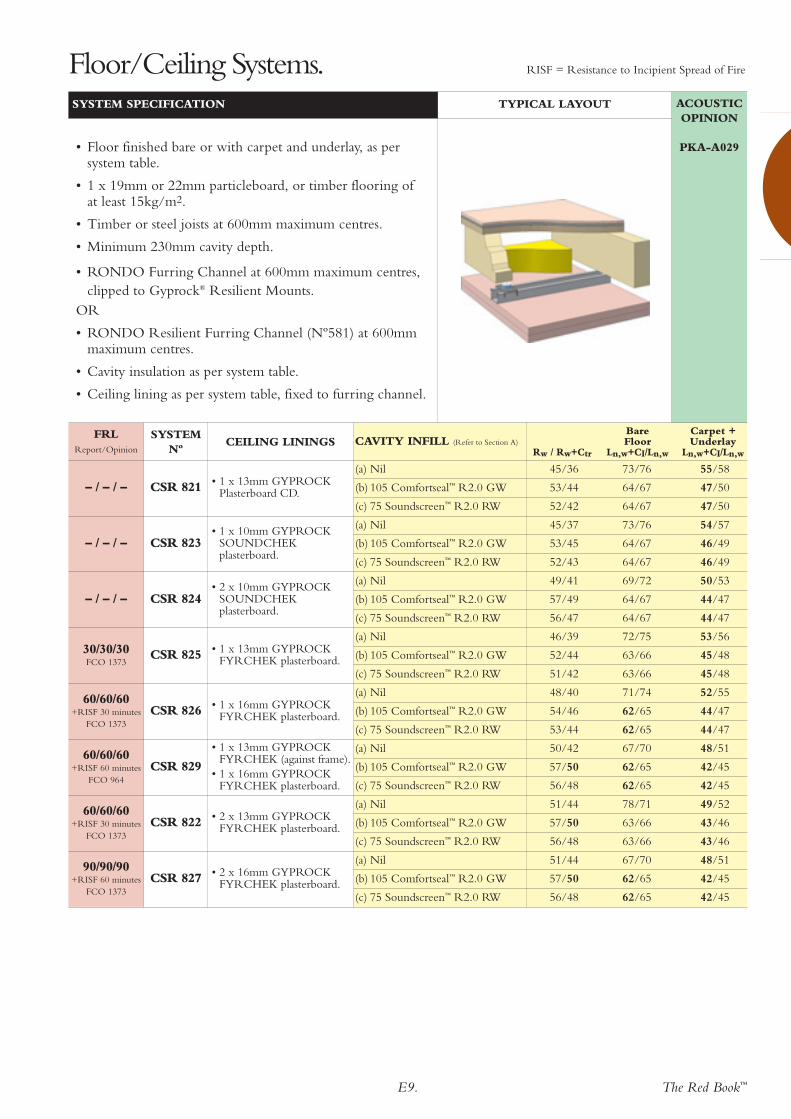
• Floor finished bare or with carpet and underlay, as persystem table.
• 1 x 19mm or 22mm particleboard, or timber flooring ofat least 15kg/m2.
• Timber or steel joists at 600mm maximum centres.
• Minimum 230mm cavity depth.
• RONDO Furring Channel at 600mm maximum centres,clipped to Gyprock® Resilient Mounts.
OR
• RONDO Resilient Furring Channel (Nº581) at 600mmmaximum centres.
• Cavity insulation as per system table.
• Ceiling lining as per system table, fixed to furring channel.
Bare Carpet + CAVITY INFILL (Refer to Section A) Floor Underlay
Rw / Rw+Ctr Ln,w+CI/Ln,w Ln,w+CI/Ln,w
Floor/Ceiling Systems. RISF = Resistance to Incipient Spread of Fire

E10. The Red Book™
120/120/120+RISF 60 minutes
FCO 1373
(a) Nil 51/45 75/72 56/53
(b) 105 Comfortseal™ R2.0 GW 57/51 70/67 51/48
(c) 75 Soundscreen™ R2.0 RW 56/49 70/67 51/48
CSR 838 • 3 x 16mm GYPROCKFYRCHEK plasterboard.
90/90/90+RISF 60 minutes
FCO 1373
(a) Nil 50/43 76/73 57/54
(b) 105 Comfortseal™ R2.0 GW 56/49 71/68 52/49
(c) 75 Soundscreen™ R2.0 RW 55/47 71/68 52/49
CSR 837 • 2 x 16mm GYPROCKFYRCHEK plasterboard.
60/60/60+RISF 60 minutes
FCO 964
(a) Nil 50/43 76/73 57/54
(b) 105 Comfortseal™ R2.0 GW 56/49 72/69 52/49
(c) 75 Soundscreen™ R2.0 RW 55/47 72/69 52/49
CSR 839
• 1 x 13mm GYPROCKFYRCHEK (against frame).
• 1 x 16mm GYPROCKFYRCHEK plasterboard.
60/60/60+RISF 30 minutes
FCO 1373
(a) Nil 47/39 78/75 58/55
(b) 105 Comfortseal™ R2.0 GW 53/45 73/70 53/50
(c) 75 Soundscreen™ R2.0 RW 52/43 73/70 53/50
CSR 836 • 1 x 16mm GYPROCKFYRCHEK plasterboard.
30/30/30FCO 1373
(a) Nil 46/38 77/74 57/54
(b) 105 Comfortseal™ R2.0 GW 52/44 72/69 52/49
(c) 75 Soundscreen™ R2.0 RW 51/42 72/69 52/49
CSR 835 • 1 x 13mm GYPROCKFYRCHEK plasterboard.
– / – / –(a) Nil 48/41 76/73 57/54
(b) 105 Comfortseal™ R2.0 GW 54/47 72/69 52/49
(c) 75 Soundscreen™ R2.0 RW 53/45 72/69 52/49
CSR 834• 2 x 10mm GYPROCK
SOUNDCHEKplasterboard.
– / – / –(a) Nil 48/41 76/73 57/54
(b) 105 Comfortseal™ R2.0 GW 54/47 72/69 52/49
(c) 75 Soundscreen™ R2.0 RW 53/45 72/69 52/49
CSR 832 • 2 x 13mm GYPROCKPlasterboard CD.
– / – / –(a) Nil 45/37 77/74 57/54
(b) 105 Comfortseal™ R2.0 GW 51/43 72/69 52/49
(c) 75 Soundscreen™ R2.0 RW 50/41 72/69 52/49
CSR 833• 1 x 10mm GYPROCK
SOUNDCHEKplasterboard.
– / – / –(a) Nil 45/37 78/75 58/55
(b) 105 Comfortseal™ R2.0 GW 51/43 73/70 53/50
(c) 75 Soundscreen™ R2.0 RW 50/41 73/70 53/50
CSR 831 • 1 x 13mm GYPROCKPlasterboard CD.
ACOUSTICOPINION
PKA-A029
SYSTEM SPECIFICATION TYPICAL LAYOUT
• Floor finished bare or with carpet and underlay, as persystem table.
• 1 x 19mm or 22mm particleboard, or timber flooring ofat least 15kg/m2.
• Timber or steel joists at 600mm maximum centres.
• Minimum 340mm cavity depth.
• RONDO Suspended Ceiling System
• Cavity insulation as per system table.
• Ceiling lining as per system table, fixed to furring channel.
Floor/Ceiling Systems. RISF = Resistance to Incipient Spread of Fire
FRLReport/Opinion
SYSTEM Nº
CEILING LININGSBare Carpet +
CAVITY INFILL (Refer to Section A) Floor UnderlayRw / Rw+Ctr Ln,w+CI/Ln,w Ln,w+CI/Ln,w

The Red Book™E11.
120/120/120+RISF 60 minutes
FCO 1373
(a) Nil 52/46 66/69 46/49
(b) 105 Comfortseal™ R2.0 GW 61/55 61/64 41/44
(c) 75 Soundscreen™ R2.0 RW 60/53 61/64 41/44
CSR 848 • 3 x 16mm GYPROCKFYRCHEK plasterboard.
90/90/90+RISF 60 minutes
FCO 1373
(a) Nil 52/45 67/70 47/50
(b) 105 Comfortseal™ R2.0 GW 60/53 62/65 42/45
(c) 75 Soundscreen™ R2.0 RW 59/51 62/65 42/45
CSR 847 • 2 x 16mm GYPROCKFYRCHEK plasterboard.
60/60/60+RISF 60 minutes
FCO 964
(a) Nil 53/46 67/70 47/50
(b) 105 Comfortseal™ R2.0 GW 60/53 62/65 42/45
(c) 75 Soundscreen™ R2.0 RW 59/51 62/65 42/45
CSR 849
• 1 x 13mm GYPROCKFYRCHEK (against frame).
• 1 x 16mm GYPROCKFYRCHEK plasterboard.
60/60/60+RISF 30 minutes
FCO 1373
(a) Nil 47/40 71/76 47/50
(b) 105 Comfortseal™ R2.0 GW 54/47 62/65 42/45
(c) 75 Soundscreen™ R2.0 RW 53/45 62/65 42/45
CSR 846 • 1 x 16mm GYPROCKFYRCHEK plasterboard.
30/30/30FCO 1373
(a) Nil 47/39 – –
(b) 105 Comfortseal™ R2.0 GW 54/46 – –
(c) 75 Soundscreen™ R2.0 RW 53/44 – –
CSR 845 • 1 x 13mm GYPROCKFYRCHEK plasterboard.
– / – / –(a) Nil 47/39 – –
(b) 105 Comfortseal™ R2.0 GW 54/47 – –
(c) 75 Soundscreen™ R2.0 RW 53/35 – –
CSR 841 • 1 x 13mm GYPROCKPlasterboard CD.
ACOUSTICOPINION
PKA-A029
SYSTEM SPECIFICATION TYPICAL LAYOUT
• Floor finished bare or with carpet and underlay, as persystem table.
• 1 x 19mm or 22mm particleboard, or timber flooring ofat least 15kg/m2.
• Timber or steel joists at 600mm maximum centres.
• Minimum 340mm cavity depth.
• RONDO Suspended Ceiling System with Gyprock®
Resilient Mounts.
• Cavity insulation as per system table.
• Ceiling lining as per system table, fixed to furring channel.
Floor/Ceiling Systems. RISF = Resistance to Incipient Spread of Fire
FRLReport/Opinion
SYSTEM Nº
CEILING LININGSBare Carpet +
CAVITY INFILL (Refer to Section A) Floor UnderlayRw / Rw+Ctr Ln,w+CI/Ln,w Ln,w+CI/Ln,w

E12. The Red Book™
120/120/120+RISF 60 minutes
FCO 1373
(a) 130 Comfortseal™ R2.5 GW 54/45 51/46 52/47
(b) 115 Soundscreen™ R3.0 RW 54/45 51/46 52/47CSR 955 • 3 x 16mm GYPROCK
FYRCHEK plasterboard.
90/90/90+RISF 60 minutes
FCO 1373
(a) 130 Comfortseal™ R2.5 GW 51/42 47/42 49/43
(b) 115 Soundscreen™ R3.0 RW 51/42 47/42 49/43CSR 871 • 2 x 16mm GYPROCK
FYRCHEK plasterboard.
60/60/60+RISF 60 minutes
FCO 964
(a) 130 Comfortseal™ R2.5 GW 50/41 46/42 49/43
(b) 115 Soundscreen™ R3.0 RW 50/41 46/42 49/43CSR 870
• 1 x 13mm GYPROCKFYRCHEK (against frame).
• 1 x 16mm GYPROCKFYRCHEK plasterboard.
– / – / –(a) 130 Comfortseal™ R2.5 GW 49/40 46/41 49/43
(b) 115 Soundscreen™ R3.0 RW 49/40 46/41 49/43CSR 953
• 1 x 13mm GYPROCKSOUNDCHEKplasterboard.
– / – / –(a) 130 Comfortseal™ R2.5 GW 45/36 42/37 45/39
(b) 115 Soundscreen™ R3.0 RW 45/36 42/37 45/39CSR 952 • 1 x 13mm GYPROCK
Plasterboard CD.
– / – / –(a) 130 Comfortseal™ R2.5 GW 53/44 51/45 52/46
(b) 115 Soundscreen™ R3.0 RW 53/44 51/45 52/46CSR 951
• 2 x 10mm GYPROCKSOUNDCHEKplasterboard.
– / – / –(a) 130 Comfortseal™ R2.5 GW 46/37 45/39 46/40
(b) 115 Soundscreen™ R3.0 RW 46/37 45/39 46/40CSR 950
• 1 x 10mm GYPROCKSOUNDCHEKplasterboard.
ACOUSTICOPINION
PKA-A030
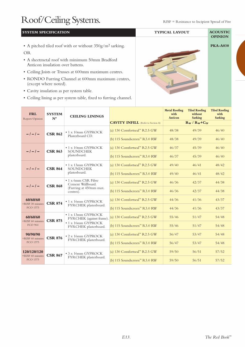
SYSTEM SPECIFICATION TYPICAL LAYOUT
• A pitched tiled roof with or without 350g/m2 sarking.
OR
• A sheetmetal roof with minimum 50mm BradfordAnticon insulation over battens.
• Ceiling Joists or Trusses at 600mm maximum centres.
• Cavity insulation as per system table.
• Ceiling lining as per system table, fixed to framing.
Roof/Ceiling Systems. RISF = Resistance to Incipient Spread of Fire
FRLReport/Opinion
SYSTEM Nº
CEILING LININGS
Metal Roofing Tiled Roofing Tiled Roofingwith without with
Anticon Sarking Sarking
CAVITY INFILL (Refer to Section A) Rw / Rw+Ctr
The Red Book™E13.
120/120/120+RISF 60 minutes
FCO 1373
(a) 130 Comfortseal™ R2.5 GW 59/50 56/51 57/52
(b) 115 Soundscreen™ R3.0 RW 59/50 56/51 57/52CSR 867 • 3 x 16mm GYPROCK
FYRCHEK plasterboard.
90/90/90+RISF 60 minutes
FCO 1373
(a) 130 Comfortseal™ R2.5 GW 56/47 53/47 54/48
(b) 115 Soundscreen™ R3.0 RW 56/47 53/47 54/48CSR 876 • 2 x 16mm GYPROCK
FYRCHEK plasterboard.
60/60/60+RISF 60 minutes
FCO 964
(a) 130 Comfortseal™ R2.5 GW 55/46 51/47 54/48
(b) 115 Soundscreen™ R3.0 RW 55/46 51/47 54/48CSR 875
• 1 x 13mm GYPROCKFYRCHEK (against frame).
• 1 x 16mm GYPROCKFYRCHEK plasterboard.
60/60/60+RISF 30 minutes
FCO 1373
(a) 130 Comfortseal™ R2.5 GW 44/36 41/36 43/37
(b) 115 Soundscreen™ R3.0 RW 44/36 41/36 43/37CSR 874 • 1 x 16mm GYPROCK
FYRCHEK plasterboard.
– / – / –(a) 130 Comfortseal™ R2.5 GW 46/36 42/37 44/38
(b) 115 Soundscreen™ R3.0 RW 46/36 42/37 44/38CSR 868
• 1 x 6mm CSR FibreCement Wallboard. (Furring at 450mm max.centres).
– / – / –(a) 130 Comfortseal™ R2.5 GW 49/40 46/41 48/42
(b) 115 Soundscreen™ R3.0 RW 49/40 46/41 48/42CSR 864
• 1 x 13mm GYPROCKSOUNDCHEKplasterboard.
– / – / –(a) 130 Comfortseal™ R2.5 GW 46/37 45/39 46/40
(b) 115 Soundscreen™ R3.0 RW 46/37 45/39 46/40CSR 863
• 1 x 10mm GYPROCKSOUNDCHEKplasterboard.
– / – / –(a) 130 Comfortseal™ R2.5 GW 48/38 49/39 46/40
(b) 115 Soundscreen™ R3.0 RW 48/38 49/39 46/40CSR 862 • 1 x 10mm GYPROCK
Plasterboard CD.
ACOUSTICOPINION
PKA-A030
SYSTEM SPECIFICATION TYPICAL LAYOUT
• A pitched tiled roof with or without 350g/m2 sarking.
OR
• A sheetmetal roof with minimum 50mm BradfordAnticon insulation over battens.
• Ceiling Joists or Trusses at 600mm maximum centres.
• RONDO Furring Channel at 600mm maximum centres,(except where noted).
• Cavity insulation as per system table.
• Ceiling lining as per system table, fixed to furring channel.
Roof/Ceiling Systems. RISF = Resistance to Incipient Spread of Fire
FRLReport/Opinion
SYSTEM Nº
CEILING LININGS
Metal Roofing Tiled Roofing Tiled Roofingwith without with
Anticon Sarking Sarking
CAVITY INFILL (Refer to Section A) Rw / Rw+Ctr

E14. The Red Book™
120/120/120+RISF 60 minutes
FCO 1373
(a) 130 Comfortseal™ R2.5 GW 61/52 58/53 59/54
(b) 115 Soundscreen™ R3.0 RW 61/52 58/53 59/54CSR 859 • 3 x 16mm GYPROCK
FYRCHEK plasterboard.
90/90/90+RISF 60 minutes
FCO 1373
(a) 130 Comfortseal™ R2.5 GW 58/49 55/49 56/50
(b) 115 Soundscreen™ R3.0 RW 58/49 55/49 56/50CSR 858 • 2 x 16mm GYPROCK
FYRCHEK plasterboard.
60/60/60+RISF 60 minutes
FCO 964
(a) 130 Comfortseal™ R2.5 GW 57/48 53/49 56/50
(b) 115 Soundscreen™ R3.0 RW 57/48 53/49 56/50
CSR 857
• 1 x 13mm GYPROCKFYRCHEK plasterboard(against frame).
• 1 x 16mm GYPROCKFYRCHEK plasterboard.
60/60/60+RISF 30 minutes
FCO 1373
(a) 130 Comfortseal™ R2.5 GW 46/38 43/38 45/39
(b) 115 Soundscreen™ R3.0 RW 46/38 43/38 45/39CSR 856 • 1 x 16mm GYPROCK
FYRCHEK plasterboard.
– / – / –(a) 130 Comfortseal™ R2.5 GW 51/42 48/43 50/44
(b) 115 Soundscreen™ R3.0 RW 51/42 48/43 50/44CSR 853
• 1 x 13mm GYPROCKSOUNDCHEKplasterboard.
– / – / –(a) 130 Comfortseal™ R2.5 GW 53/44 50/44 51/45
(b) 115 Soundscreen™ R3.0 RW 53/44 50/44 51/45CSR 852
• 2 x 10mm GYPROCKSOUNDCHEKplasterboard.
– / – / –(a) 130 Comfortseal™ R2.5 GW 48/39 47/41 48/42
(b) 115 Soundscreen™ R3.0 RW 48/39 47/41 48/42CSR 851
• 1 x 10mm GYPROCKSOUNDCHEKplasterboard.
ACOUSTICOPINION
PKA-A030
SYSTEM SPECIFICATION TYPICAL LAYOUT
• A pitched tiled roof with or without 350g/m2 sarking.
OR
• A sheetmetal roof with minimum 50mm BradfordAnticon insulation over battens.
• Ceiling Joists or Trusses at 600mm maximum centres.
• RONDO Furring Channel at 600mm maximum centres,clipped to Gyprock® Resilient Mounts.
• Cavity insulation as per system table.
• Ceiling lining as per system table, fixed to furring channel.
Roof/Ceiling Systems. RISF = Resistance to Incipient Spread of Fire
FRLReport/Opinion
SYSTEM Nº
CEILING LININGS
Metal Roofing Tiled Roofing Tiled Roofingwith without with
Anticon Sarking Sarking
CAVITY INFILL (Refer to Section A) Rw / Rw+Ctr

The Red Book™E15.
120/120/120+RISF 60 minutes
FCO 1373
(a) 130 Comfortseal™ R2.5 GW –
(b) 115 Soundscreen™ R3.0 RW –CSR 866 • 3 x 16mm GYPROCK
FYRCHEK plasterboard.
90/90/90+RISF 60 minutes
FCO 1373
(a) 130 Comfortseal™ R2.5 GW 51/44
(b) 115 Soundscreen™ R3.0 RW 51/44CSR 865 • 2 x 16mm GYPROCK
FYRCHEK plasterboard.
– / – / –(a) 130 Comfortseal™ R2.5 GW 49/44
(b) 115 Soundscreen™ R3.0 RW 49/44CSR 860 • 1 x 13mm GYPROCK
Plasterboard CD.
ACOUSTICOPINION
PKA-A030
SYSTEM SPECIFICATION TYPICAL LAYOUT
• Metal deck roof
• Bradford R1.5 Glasswool Blanket over timber or steelpurlins hard under roof.
• RONDO Suspended Ceiling System with Gyprock®
Resilient Mounts.
• Cavity insulation as per system table.
• Ceiling lining as per system table, fixed to furring channel.
Roof/Ceiling Systems. RISF = Resistance to Incipient Spread of Fire
FRLReport/Opinion
SYSTEM Nº
CEILING LININGS CAVITY INFILL (Refer to Section A) Rw / Rw+Ctr
ACOUSTICOPINION
PKA-A030
SYSTEM SPECIFICATION TYPICAL LAYOUT
• A low slope metal roof.
• Timber or Steel Purlins at 1200mm maximum centres.
• RONDO Furring Channel at 600mm maximum centres,fixed to purlin with fixing clips (Nº226).
• Cavity insulation as per system table.
• Ceiling lining as per system table, fixed to furring channel.
FRLReport/Opinion
SYSTEM Nº
CEILING LININGS CAVITY INFILL (Refer to Section A) Rw / Rw+Ctr
ACOUSTICOPINION
PKA-A030
SYSTEM SPECIFICATION TYPICAL LAYOUT
• Timber or steel framing to engineer’s detail.
• CSR ExpressWall™ top hat framing system.
• Ceiling lining as per system table, fixed to framing.
– / – / – (a) Nil –CSR 869 1 x CSR ExpressPanel™.
FRLReport/Opinion
SYSTEM Nº
CEILING LININGS CAVITY INFILL (Refer to Section A) Rw / Rw+Ctr

E16. The Red Book™
120/120/120from top
onlyFAR 2358
(a) Nil 36/34CSR 985
ABOVE• 3 x 16mm GYPROCK FYRCHEK.BELOW• Nil.
90/90/90from top
onlyFAR 2358
(a) Nil 36/34CSR 986
ABOVE• 3 x 13mm GYPROCK FYRCHEK.BELOW• Nil.
120/120/120from top
onlyFAR 2358
(a) Nil 46/37
(b) 50 Glasswool Partition batts 50/41CSR 983
ABOVE• 2 x 16mm GYPROCK FYRCHEK.BELOW• 1 x 10mm GYPROCK Plasterboard CD.
60/60/60from top
onlyFAR 2358
(a) Nil 34/–CSR 982
ABOVE• 2 x 16mm GYPROCK FYRCHEK.BELOW• Nil.
60/60/60from top
onlyFAR 2358
(a) Nil 40/31
(b) 50 Glasswool Partition batts 44/35CSR 981
ABOVE• 1 x 16mm GYPROCK FYRCHEK.BELOW• 1 x 10mm GYPROCK Plasterboard CD.
ACOUSTICOPINION
PKA-A025
SYSTEM SPECIFICATION TYPICAL LAYOUT
• Ceiling lining as per system table, fixed to framing.
• Steel framing maximum 1.6 BMT at 600mm maximumcentres.
• Minimum cavity depth 150mm.
• Cavity insulation as per system table.
• Ceiling lining as per system table, fixed to framing.
Floor or Ceiling Fire Rated from Above.
FRLReport/Opinion
SYSTEM Nº
CEILING LININGS CAVITY INFILL Rw / Rw+Ctr
240/240/240from top
onlyRefer to
CSR Hebel
(a) Nil 33/30 45SF001ABOVE
• 1 x CSR HebelSoundFloor™.
ACOUSTICOPINION
Refer to CSR Hebel
SYSTEM SPECIFICATION – HEBEL SOUNDFLOOR TYPICAL LAYOUT
• Carpet and medium duty underlay.
• CSR Hebel SoundFloor™, as per system table.
• Timber or steel joists at 600mm maximum centres.
Note: Refer to CSR Hebel for design considerations.
FRLReport/Opinion
SYSTEM Nº
CEILING LININGS CAVITY INFILL Rw / Rw+Ctr Ln,w+CI

The Red Book™E17.
120/120/120+RISF 60 minutes
FAR 2358
(a) Nil 54/46
(b) 50 Glasswool Partition batts 58/50
CSR 993
ABOVE
• 2 x 16mm GYPROCKFYRCHEK plasterboard.
BELOW
• 3 x 16mm GYPROCKFYRCHEK plasterboard.
90/90/90from below120/120/120from above+RISF 60 minutes
FAR 2358
(a) Nil 51/43
(b) 50 Glasswool Partition batts 55/47
CSR 992ABOVE & BELOW
• 2 x 16mm GYPROCKFYRCHEK plasterboard.
120/120/120+RISF 60 minutes
FAR 2358
(a) Nil 47/37 49/41
(b) 50 Glasswool Partition batts 53/43 54/46
CSR 997
ABOVE
• 1 x 25mm GYPROCKSHAFT LINER PANEL.
BELOW
• 3 x 16mm GYPROCKFYRCHEK plasterboard.
90/90/90+RISF 60 minutes
FAR 2358
(a) Nil 45/35 47/39
(b) 50 Glasswool Partition batts 51/41 52/44
CSR 995
ABOVE
• 1 x 25mm GYPROCKSHAFT LINER PANEL.
BELOW
• 2 x 16mm GYPROCKFYRCHEK plasterboard.
60/60/60from top
onlyFAR 2358
(a) Nil 41/30 43/34
(b) 50 Glasswool Partition batts 47/36 48/39
CSR 987
ABOVE
• 1 x 25mm GYPROCKSHAFT LINER PANEL.
BELOW
• 1 x 16mm GYPROCKFYRCHEK plasterboard.
ACOUSTICOPINION
PKA-A025
SYSTEM SPECIFICATION TYPICAL LAYOUT
• Shaftwall C-H studs at 600mm maximum centres.
• Lining to top side as per system table, in framing.
• Cavity insulation as per system table.
• Ceiling lining as per system table, fixed to framing.
Ceilings Fire Rated from Above and/or Below.
FRLReport/Opinion
SYSTEM Nº
CEILING LININGSCAVITY INFILL (Refer to Section A) Rw / Rw+Ctr
STUD DEPTH 64 102
RISF = Resistance to Incipient Spread of Fire
60/60/60FAR 2358
(a) Nil 43/35
(b) 50 Glasswool Partition batts 47/39CSR 994
ABOVE & BELOW
• 1 x 16mm GYPROCKFYRCHEK plasterboard.
ACOUSTICOPINION
PKA-A025
SYSTEM SPECIFICATION TYPICAL LAYOUT
• Ceiling lining as per system table, fixed to framing.
• Steel framing maximum 1.6mm BMT at 600mmmaximum centres.
• Cavity insulation as per system table.
• Ceiling lining as per system table, fixed to framing.
FRLReport/Opinion
SYSTEM Nº
CEILING LININGSCAVITY INFILL (Refer to Section A) Rw / Rw+Ctr
STUD DEPTH 150
RISF = Resistance to Incipient Spread of Fire
E18. The Red Book™
ACOUSTICOPINION
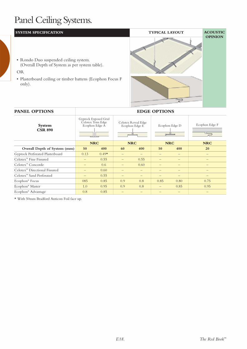
SYSTEM SPECIFICATION TYPICAL LAYOUT
• Rondo Duo suspended ceiling system.(Overall Depth of System as per system table).
OR
• Plasterboard ceiling or timber battens (Ecophon Focus Fonly).
Panel Ceiling Systems.
NRC NRC NRC NRC
Overall Depth of System (mm) 50 400 60 400 50 400 20
Gyprock Perforated Plasterboard 0.13 0.49* – – – – –
Celotex™ Fine Fissured – 0.55 – 0.55 – – –
Celotex™ Concorde – 0.6 – 0.60 – – –
Celotex™ Directional Fissured – 0.60 – – – – –
Celotex™ Sand Perforated – 0.55 – – – – –
Ecophon® Focus 085 0.85 0.9 0.8 0.85 0.80 0.75
Ecophon® Master 1.0 0.95 0.9 0.8 – 0.85 0.95
Ecophon® Advantage 0.8 0.85 – – – – –
PANEL OPTIONS EDGE OPTIONS
Gyprock Exposed GridCelotex Trim EdgeEcophon Edge A
Celotex Reveal EdgeEcophon Edge E Ecophon Edge D Ecophon Edge FSystem
CSR 890
* With 50mm Bradford Anticon Foil face up.

The Red Book™E19.
300mm max.
200mm max.
Butt Joints in 1st layer may be on same member
Offset Butt Joints in 2nd layer 600mm min. in adjoining sheets and between layers
Begin 1st layer with a half width sheet
Begin 2nd layer with a full width sheet and offset recessed joint 300mm minimum between 1st and 2nd layer
Timber or Steel Framing at 600mm max. centres
For Level of Finish 4 and 5, where Butt Jointing is unavoidable, joint centrally between members, fix with laminating screws at 200mm
For Levels of Finish 0 to 3, Butt Joint on member and screw fix at 200mm max. centres
230mm max.
300mm max. for cornice finish150mm max. for set finish
200mm min.
230mm max.
200mm min.Adhesive Daubs
Temporary block
FIG E4. INSTALLATION DETAIL. TWO LAYER – ADHESIVE & SCREW FIXING.
Fixing & SpacingScrew fix to eachframing member at300mm max. centres4 screws equally spaced5 screws equally spaced6 screws equally spacedScrew fix at 200mm max.centresScrew fix at 300mmmax. centresFixing & SpacingAdhesive Daubs at230mm max. centresand 200mm min. fromfastener points2 daubs4 daubs4 daubsScrew fix at eachframe member.Screw fix at each framemember.Screw fix at 200mm max.centres.Laminating screws at200mm max. centres
Screws at 200mm max.centres.For cornice finish, screwfix at 300mm max. cts.For set finish, screw fixat 150mm max. centres
1st LayerBodySheetWidth900mm1200mm1350mmButt Jointson framingSheet Ends& Openings2nd LayerBody
Sheet Width900mm1200mm1350mmRecessedJointsCentreline of SheetButt Jointson framingButt jointsbetweenframingOpenings
Sheet Ends
Fixing Specifications1st LayerScrews Refer to Section ‘A’.2nd LayerFasteners Refer to Section ‘A’.Adhesive Gyprock Stud Adhesive
230mmmax.centres
200mmmin. cts
200mmmin. cts
For 1350mm width sheets, hold sheet with temporary fastener through block at every second joist until adhesive sets
Timber or steel framing
2 Nails 50 to 75mm apartor 1 screw
Offset butt joints in adjoining sheets by 600mm minimum
Adhesive Daubs
For Level of Finish 4 and 5, where Butt Jointing is unavoidable, joint centrally between members and back-block.
Where permitted, Butt Joint on member (Levels of Finish 0 to 3)
Nail at 150mmor screw at 200mm max.
300mm max. for cornice finish150mm max. for set finish
FIG E3. INSTALLATION DETAIL. SINGLE LAYER – ADHESIVE & NAIL/SCREW FIXING.
Fixing & SpacingAdhesive Daubs at230mm max. centresand 200mm min. fromfastener points2 daubs4 daubs4 daubsNail/screw fix at eachframe member2 nails at 50 to 75mmapart or 1 screw at eachframe memberJoint within 50mm ofcentre line betweenframing and adhesive fixback-blockNail fix at 150mm orscrew fix at 200mm max.centresNail fix at 150mm orscrew fix at 200mm max.centres.For cornice finish, fastenat 300mm max. cts.For set finish, fasten at150mm max. centres
LocationField
Sheet Width900mm1200mm1350mmRecessedJointsCentreline of SheetButt Jointsbetweenframing
Butt Jointson framing
Openings
Sheet Ends
Fixing SpecificationsFasteners Refer to Section ‘A’.Adhesive Gyprock Stud Adhesive
NON FIRE RATED
NON FIRE RATED

E20. The Red Book™
Fixing SpecificationsScrews Refer to Section ‘A’.
200mm max.
300mm max. for cornice finish150mm max. for set finish
Offset butt joints in adjoining sheets by 600mm minimum
For Level of Finish 4 and 5, where Butt Jointing is unavoidable, support plasterboard with additional framing (Refer to FIG. 13)
Where permitted, Butt Joint on member and screw fix at 200mm max. centres (Levels of Finish 0 to 3)
200mm max.
Structural support of timber, steel or concrete
300mm max.
Suspended Grid at 600mm maximum centres
Practical minimum 150mm
FIG E5. INSTALLATION DETAIL. SINGLE LAYER – SCREW FIXING.
Fixing & SpacingScrew fix to each frameat 10 to 16mm fromsheet edges and at300mm max. centresbetween.4 screws equally spaced5 screws equally spaced6 screws equally spacedJoint within 50mm ofcentre line betweenframing. Back-block andfix with laminatingscrews at 200mm max.centres.Screw fix at 200mm max.centresScrew fix at 200mmmax. centres. For cornice finish, screwfix at 300mm max. cts.For set finish, screw fixat 150mm max. centres
LocationRecessedJoints &BodySheetWidth900mm1200mm1350mmButt Jointsbetweenframing
Butt Jointson framingOpenings
Sheet Ends
Framing at 600mm centres
25mm GYPROCK screwsat 300mm centres
At butt joints, screw at 200mm centres opposed
Staggered butt joints
GYPROCK Perforated Plasterboard(perforations not shown)
Border of standard GYPROCK plasterboardor finish with wall angle trim
FIG E6. INSTALLATION DETAIL.PERFORATED PLASTERBOARD SHEETS.
NON FIRE RATED
Fixing SpecificationsScrews Refer to Section ‘A’.
Fixing & SpacingScrew fix to each frameat 10 to 16mm fromsheet edges and at300mm max. centresbetween.Screw fix at 200mmmax. centres.Screw fix at 200mmmax. centresScrew fix at 200mmmax. centres.
LocationRecessedJoints &Body
Butt Jointson framingSheet Ends
Openings
NON FIRE RATED

The Red Book™E21.
Fixing & SpacingFasten to each framingmember at 10 to 16mm from sheetedges and at 200mmmax. centresButt Joint on framing andfasten at 150mm max.centres.
Butt Joint within 50mmof centre line betweenframing and fix toprevious layer withLaminating Screws at200mm max. centresCornice finish, fasten at200mm max. centresSet finish, fasten at150mm max. centresFasten at 150mm max. centres
LocationBody ofSheetAll Layers
Butt Joints 1st & 2ndLayersButt Joints 3rd layer
Sheet Ends
Openings
Fixing SpecificationsFasteners Refer to Section ‘A’.
200mm max.
150/200mm max.
200mm max.
150mmmax.
150mmmax.
Butt Joints in 3rd layer must be placed centrally between framing, offset 600mm minimum in adjoining sheets and from previous layers
Begin 1st layer with 400mm width sheetBegin 2nd layer with 800mm width sheetBegin 3rd layer with full width sheet
1st and 2nd layer Butt Joints on framing members, offset 600mm minimum between layers
Suspended Grid, Steel Framing or Timber Framing at 600mm maximum centres
Perimeter track/angle required in fire rated ceiling systems (refer to Perimeter Framing & Caulking)
FIG E8. INSTALLATION DETAIL. THREE LAYER FIXING TO STEEL OR TIMBER FRAMING – NAIL OR SCREW FIXING.
Fixing SpecificationsFasteners Refer to Section ‘A’.
200mm max.
150/200mm max.
200mm max.
150mmmax.
Butt Joints in 1st layer may be on same member
Butt Joints in 2nd layer must be offset 600mm minimum in adjoining sheets and between layers
Begin 1st layer with half width sheet
Begin 2nd layer with full width sheet and offset recessed joint 300mm minimum between 1st and 2nd layer
For framing at 600mm max. centres, Butt Joints in 2nd layer must be centred between framing members
For framing at 450mm centres, Butt Joints in 2nd layer may be on or centrally between framing members
Refer to system specifications
Perimeter track/angle required in fire rated ceiling systems (refer to Perimeter Framing & Caulking)
FIG E7. INSTALLATION DETAIL. ONE OR TWO LAYER – NAIL OR SCREW FIXING.
FOR SYSTEMS WITH LINING ABOVE OR BELLOW FRAMING.
Fixing & SpacingFasten to each framingmember at 10 to 16mmfrom sheet edges and at200mm maximumcentresButt Joint on framing andfasten at 150mm max.centres.Framing at 450mm max.spacing – Butt Joint onframing and fasten at150mm max. centres (oras detailed for 600mmframe spacing).Framing at 600mm max.spacing – Butt Jointwithin 50mm of centreline between framingand fix to 1st layer withLaminating Screws at200mm max. centresFasten at 150mm max. centresCornice finish – Fastenat 200mm max. centresSet finish – Fasten at150mm max. centres
LocationBody ofSheet1st & 2ndLayer
Butt Joints 1st layer Butt Joints 2nd layer
Openings
Sheet Ends
FIRE RATED
FIRE RATED
Note: Single layer systems to be fixedas per 2nd layer, Butt joints betweenframing are to be fully back blockedand fixed with laminating screws.

E22. The Red Book™
Fixing & SpacingFix to upper framing atmax. 300 centres.Fix lower framingthrough to upper framingat 200mm max. centres.Fix to upper framing at300mm max. centres.Fix lower framingthrough to upper framingat 150mm max. centres.Fix at 150mm max.centres.
LocationBody ofSheetAll Layers
Butt Joints
Sheet Ends
Top Layers Fixing SpecificationsFasteners Refer to Section ‘A’.
FIRE RATED
150mmmax.
150mmmax.
150mmmax.
200mmmax.
300mmmax.
150mmmax.
200mmmax.
FIG E9. INSTALLATION DETAIL. PLASTERBOARD FIXING TO STEEL FRAMING – FIRE RATED FROM ABOVE AND/OR BELOW.
Bottom Layers Fixing SpecificationsFasteners Refer to Section ‘A’.
Fixing & SpacingFasten to each framingmember at 10 to 16mmfrom sheet edges and at200mm max. centres.
7 fasteners equally spaced8 fasteners equally spacedFraming at 450mm max.spacing – Butt Joint onframing and fasten at150mm max. centres.ORFraming at 600mm max.spacing – Butt Jointwithin 50mm of centreline between framing.Fully backblock and fixwith laminating Screwsat 200mm max. centres.Fasten at 150mm max. centresCornice finish – Fastenat 200mm max. centresSet finish – Fasten at150mm max. centres
LocationBody ofSheet
SheetWidth1200mm1350mmButt Joints
Openings
Sheet Ends
FIRE RATED
SUITABLE FOR: