datapower redbook
286
ibm.com/redbooks Draft Document for Review April 13, 2011 6:45 am SG24-7901-00 DataPower SOA Appliance Administration, Deployment, and Best Practices Gerry Kaplan Ronnie Mitra Jan Bechtold Helio L. P. Mota David Shute Daniel Dickerson Richard Kinard John Walczyk User Administration and Role-Based Management Network Configuration, Monitoring, and Logging Appliance and Configuration Management
-
Upload
webspheredude -
Category
Documents
-
view
3.105 -
download
14
Transcript of datapower redbook
ibm.com/redbooks
Draft Document for Review April 13, 2011 6:45 am SG24-7901-00
DataPower SOA ApplianceAdministration, Deployment,and Best Practices
Gerry KaplanRonnie MitraJan Bechtold
Helio L. P. MotaDavid Shute
Daniel DickersonRichard KinardJohn Walczyk
User Administration and Role-Based Management
Network Configuration, Monitoring, and Logging
Appliance and Configuration Management
Front cover

DataPower SOA Appliance Administration, Deployment, and Best Practices
April 2011
International Technical Support Organization
Draft Document for Review April 13, 2011 6:45 am 7901edno.fm
SG24-7901-00
7901edno.fm Draft Document for Review April 13, 2011 6:45 am
© Copyright International Business Machines Corporation 2011. All rights reserved.Note to U.S. Government Users Restricted Rights -- Use, duplication or disclosure restricted by GSA ADPSchedule Contract with IBM Corp.
First Edition (April 2011)
This edition applies to DataPower firmware version 3.8.2.
This document created or updated on April 13, 2011.
Note: Before using this information and the product it supports, read the information in “Notices” on page xi.
Draft Document for Review April 13, 2011 6:45 am 7901TOC.fm
Contents
Notices . . . . . . . . . . . . . . . . . . . . . . . . . . . . . . . . . . . . . . . . . . . . . . . . . . . . . . . xiTrademarks . . . . . . . . . . . . . . . . . . . . . . . . . . . . . . . . . . . . . . . . . . . . . . . . . . . xii
Preface . . . . . . . . . . . . . . . . . . . . . . . . . . . . . . . . . . . . . . . . . . . . . . . . . . . . . . xiiiThe team who wrote this book . . . . . . . . . . . . . . . . . . . . . . . . . . . . . . . . . . . . . xiiiNow you can become a published author, too! . . . . . . . . . . . . . . . . . . . . . . . . xvComments welcome. . . . . . . . . . . . . . . . . . . . . . . . . . . . . . . . . . . . . . . . . . . . . xviStay connected to IBM Redbooks . . . . . . . . . . . . . . . . . . . . . . . . . . . . . . . . . . xvi
Chapter 1. Securing user access . . . . . . . . . . . . . . . . . . . . . . . . . . . . . . . . . . 11.1 Overview . . . . . . . . . . . . . . . . . . . . . . . . . . . . . . . . . . . . . . . . . . . . . . . . . . . 21.2 Benefits . . . . . . . . . . . . . . . . . . . . . . . . . . . . . . . . . . . . . . . . . . . . . . . . . . . . 31.3 Device initialization considerations . . . . . . . . . . . . . . . . . . . . . . . . . . . . . . . 3
1.3.1 Setting up the master administrator password . . . . . . . . . . . . . . . . . . 41.3.2 Enabling Disaster Recovery Mode . . . . . . . . . . . . . . . . . . . . . . . . . . . 4
1.4 Access control lists . . . . . . . . . . . . . . . . . . . . . . . . . . . . . . . . . . . . . . . . . . . 51.5 Authentication and credential mapping . . . . . . . . . . . . . . . . . . . . . . . . . . . . 6
1.5.1 Locally managed users . . . . . . . . . . . . . . . . . . . . . . . . . . . . . . . . . . . . 61.5.2 Locally-defined user groups . . . . . . . . . . . . . . . . . . . . . . . . . . . . . . . . 71.5.3 Using local user repository for contingency . . . . . . . . . . . . . . . . . . . 131.5.4 Pros and cons of using the local user repository . . . . . . . . . . . . . . . 131.5.5 RBM policy files. . . . . . . . . . . . . . . . . . . . . . . . . . . . . . . . . . . . . . . . . 141.5.6 Remote authentication servers . . . . . . . . . . . . . . . . . . . . . . . . . . . . . 181.5.7 Single sign-on . . . . . . . . . . . . . . . . . . . . . . . . . . . . . . . . . . . . . . . . . . 221.5.8 Login processing summary . . . . . . . . . . . . . . . . . . . . . . . . . . . . . . . . 22
1.6 Audit logs. . . . . . . . . . . . . . . . . . . . . . . . . . . . . . . . . . . . . . . . . . . . . . . . . . 241.6.1 Obtaining the audit log using CLI . . . . . . . . . . . . . . . . . . . . . . . . . . . 241.6.2 Copying the audit log using SOMA . . . . . . . . . . . . . . . . . . . . . . . . . . 24
1.7 Best practices . . . . . . . . . . . . . . . . . . . . . . . . . . . . . . . . . . . . . . . . . . . . . . 251.8 Troubleshooting. . . . . . . . . . . . . . . . . . . . . . . . . . . . . . . . . . . . . . . . . . . . . 26
Chapter 2. Networking . . . . . . . . . . . . . . . . . . . . . . . . . . . . . . . . . . . . . . . . . 292.1 Overview . . . . . . . . . . . . . . . . . . . . . . . . . . . . . . . . . . . . . . . . . . . . . . . . . . 302.2 Benefits . . . . . . . . . . . . . . . . . . . . . . . . . . . . . . . . . . . . . . . . . . . . . . . . . . . 302.3 Usage . . . . . . . . . . . . . . . . . . . . . . . . . . . . . . . . . . . . . . . . . . . . . . . . . . . . 31
2.3.1 Network interface configuration and routing . . . . . . . . . . . . . . . . . . . 312.3.2 VLAN sub-interfaces . . . . . . . . . . . . . . . . . . . . . . . . . . . . . . . . . . . . . 362.3.3 Network settings . . . . . . . . . . . . . . . . . . . . . . . . . . . . . . . . . . . . . . . . 362.3.4 Host alias, static hosts, and DNS . . . . . . . . . . . . . . . . . . . . . . . . . . . 39
© Copyright IBM Corp. 2011. All rights reserved. iii
7901TOC.fm Draft Document for Review April 13, 2011 6:45 am
2.3.5 Routing . . . . . . . . . . . . . . . . . . . . . . . . . . . . . . . . . . . . . . . . . . . . . . . 402.3.6 Load balancing a backend destination . . . . . . . . . . . . . . . . . . . . . . . 412.3.7 Intelligent Load Distribution. . . . . . . . . . . . . . . . . . . . . . . . . . . . . . . . 422.3.8 Self-Balancing services. . . . . . . . . . . . . . . . . . . . . . . . . . . . . . . . . . . 432.3.9 Load Balancer health checking . . . . . . . . . . . . . . . . . . . . . . . . . . . . . 442.3.10 Standby Control and high availability . . . . . . . . . . . . . . . . . . . . . . . 45
2.4 Best practices . . . . . . . . . . . . . . . . . . . . . . . . . . . . . . . . . . . . . . . . . . . . . . 462.4.1 Avoid using 0.0.0.0 as a listener . . . . . . . . . . . . . . . . . . . . . . . . . . . . 462.4.2 Separating management traffic . . . . . . . . . . . . . . . . . . . . . . . . . . . . . 462.4.3 Specify port values less than 10,000 . . . . . . . . . . . . . . . . . . . . . . . . 472.4.4 Persistent timeout consideration . . . . . . . . . . . . . . . . . . . . . . . . . . . . 472.4.5 Disable chained persistent connections . . . . . . . . . . . . . . . . . . . . . . 472.4.6 Configure network settings to be portable. . . . . . . . . . . . . . . . . . . . . 472.4.7 Multiple default gateways will create multiple default routes. . . . . . . 482.4.8 Standby Control best practices . . . . . . . . . . . . . . . . . . . . . . . . . . . . . 482.4.9 Management interface and default route . . . . . . . . . . . . . . . . . . . . . 502.4.10 Enabling “No Delay Ack” to avoid latency with other systems . . . . 502.4.11 Streaming large messages and flow control . . . . . . . . . . . . . . . . . . 51
2.5 Examples. . . . . . . . . . . . . . . . . . . . . . . . . . . . . . . . . . . . . . . . . . . . . . . . . . 522.5.1 Externalizing endpoints in a Meta Data document . . . . . . . . . . . . . . 522.5.2 Disabling chained persistent connections for various different points of
a service . . . . . . . . . . . . . . . . . . . . . . . . . . . . . . . . . . . . . . . . . . . . . . 532.5.3 Port speed mismatch . . . . . . . . . . . . . . . . . . . . . . . . . . . . . . . . . . . . 542.5.4 Sample DNS workaround using static host . . . . . . . . . . . . . . . . . . . . 542.5.5 Sample CLI commands to capture DNS server responses. . . . . . . . 542.5.6 Sample test to see if Rapid Spanning Tree has been deployed properly
for DataPower Standby Control . . . . . . . . . . . . . . . . . . . . . . . . . . . . 552.5.7 Example of deleting routes . . . . . . . . . . . . . . . . . . . . . . . . . . . . . . . . 572.5.8 Sample XSLT for adding DataPower transaction ID to an HTTP header
for outgoing traffic . . . . . . . . . . . . . . . . . . . . . . . . . . . . . . . . . . . . . . . 58
Chapter 3. Domains. . . . . . . . . . . . . . . . . . . . . . . . . . . . . . . . . . . . . . . . . . . . 593.1 Application domains . . . . . . . . . . . . . . . . . . . . . . . . . . . . . . . . . . . . . . . . . 60
3.1.1 The default domain . . . . . . . . . . . . . . . . . . . . . . . . . . . . . . . . . . . . . . 603.1.2 Domain use and benefits . . . . . . . . . . . . . . . . . . . . . . . . . . . . . . . . . 603.1.3 Segregating projects and LOBs . . . . . . . . . . . . . . . . . . . . . . . . . . . . 623.1.4 Number of domains on an appliance . . . . . . . . . . . . . . . . . . . . . . . . 623.1.5 Domain resource consumption . . . . . . . . . . . . . . . . . . . . . . . . . . . . . 63
3.2 Domain structure . . . . . . . . . . . . . . . . . . . . . . . . . . . . . . . . . . . . . . . . . . . . 633.2.1 Local flash-based file system . . . . . . . . . . . . . . . . . . . . . . . . . . . . . . 643.2.2 Domain configuration files. . . . . . . . . . . . . . . . . . . . . . . . . . . . . . . . . 663.2.3 Domain logging . . . . . . . . . . . . . . . . . . . . . . . . . . . . . . . . . . . . . . . . . 663.2.4 Domain monitoring . . . . . . . . . . . . . . . . . . . . . . . . . . . . . . . . . . . . . . 66
iv DataPower SOA Appliance Administration, Deployment, and Best Practices
Draft Document for Review April 13, 2011 6:45 am 7901TOC.fm
3.2.5 Shared resources . . . . . . . . . . . . . . . . . . . . . . . . . . . . . . . . . . . . . . . 673.3 Domain persistence. . . . . . . . . . . . . . . . . . . . . . . . . . . . . . . . . . . . . . . . . . 67
3.3.1 Saving configuration changes . . . . . . . . . . . . . . . . . . . . . . . . . . . . . . 673.3.2 Imported domain configurations . . . . . . . . . . . . . . . . . . . . . . . . . . . . 69
3.4 Usage considerations . . . . . . . . . . . . . . . . . . . . . . . . . . . . . . . . . . . . . . . . 693.4.1 Cross-domain file visibility . . . . . . . . . . . . . . . . . . . . . . . . . . . . . . . . . 693.4.2 Domain names . . . . . . . . . . . . . . . . . . . . . . . . . . . . . . . . . . . . . . . . . 703.4.3 Restarting and resetting domains . . . . . . . . . . . . . . . . . . . . . . . . . . . 723.4.4 Quiescing . . . . . . . . . . . . . . . . . . . . . . . . . . . . . . . . . . . . . . . . . . . . . 733.4.5 Cleaning up orphaned objects . . . . . . . . . . . . . . . . . . . . . . . . . . . . . 743.4.6 Isolating domain network interface . . . . . . . . . . . . . . . . . . . . . . . . . . 743.4.7 Deleting domains . . . . . . . . . . . . . . . . . . . . . . . . . . . . . . . . . . . . . . . 75
3.5 Best practices . . . . . . . . . . . . . . . . . . . . . . . . . . . . . . . . . . . . . . . . . . . . . . 753.6 Further reading . . . . . . . . . . . . . . . . . . . . . . . . . . . . . . . . . . . . . . . . . . . . . 76
Chapter 4. SNMP monitoring . . . . . . . . . . . . . . . . . . . . . . . . . . . . . . . . . . . . 774.1 Appliance monitoring. . . . . . . . . . . . . . . . . . . . . . . . . . . . . . . . . . . . . . . . . 784.2 DataPower monitoring fundamentals . . . . . . . . . . . . . . . . . . . . . . . . . . . . 784.3 Enabling statistics . . . . . . . . . . . . . . . . . . . . . . . . . . . . . . . . . . . . . . . . . . . 794.4 SNMP monitoring . . . . . . . . . . . . . . . . . . . . . . . . . . . . . . . . . . . . . . . . . . . 80
4.4.1 SNMP protocol messages. . . . . . . . . . . . . . . . . . . . . . . . . . . . . . . . . 814.4.2 Management information base (MIB) structure. . . . . . . . . . . . . . . . . 814.4.3 SNMP traps. . . . . . . . . . . . . . . . . . . . . . . . . . . . . . . . . . . . . . . . . . . . 824.4.4 DataPower status providers . . . . . . . . . . . . . . . . . . . . . . . . . . . . . . . 824.4.5 SNMP security . . . . . . . . . . . . . . . . . . . . . . . . . . . . . . . . . . . . . . . . . 834.4.6 Configuring SNMP using the WebGUI . . . . . . . . . . . . . . . . . . . . . . . 854.4.7 Generating traps with SNMP log targets. . . . . . . . . . . . . . . . . . . . . . 93
4.5 Monitoring via the XML Management Interface. . . . . . . . . . . . . . . . . . . . . 954.5.1 Requesting device status and metrics . . . . . . . . . . . . . . . . . . . . . . . 97
4.6 Appliance monitoring values . . . . . . . . . . . . . . . . . . . . . . . . . . . . . . . . . . . 984.6.1 General device health and activity monitors . . . . . . . . . . . . . . . . . . . 994.6.2 Interface utilization statistics . . . . . . . . . . . . . . . . . . . . . . . . . . . . . . 1124.6.3 Other network status providers . . . . . . . . . . . . . . . . . . . . . . . . . . . . 120
4.7 SNMP traps . . . . . . . . . . . . . . . . . . . . . . . . . . . . . . . . . . . . . . . . . . . . . . . 1204.8 Certificate monitoring considerations . . . . . . . . . . . . . . . . . . . . . . . . . . . 1224.9 Best practices and considerations. . . . . . . . . . . . . . . . . . . . . . . . . . . . . . 124
Chapter 5. IBM Tivoli Monitoring . . . . . . . . . . . . . . . . . . . . . . . . . . . . . . . . 1255.1 IBM Tivoli Monitoring environment architecture . . . . . . . . . . . . . . . . . . . 126
5.1.1 Tivoli Management Services components . . . . . . . . . . . . . . . . . . . 1265.1.2 IBM Tivoli Composite Application Manager . . . . . . . . . . . . . . . . . . 1285.1.3 ITCAM for SOA . . . . . . . . . . . . . . . . . . . . . . . . . . . . . . . . . . . . . . . . 129
5.2 Monitoring DataPower appliances. . . . . . . . . . . . . . . . . . . . . . . . . . . . . . 131
Contents v
7901TOC.fm Draft Document for Review April 13, 2011 6:45 am
5.2.1 Monitoring DataPower application-level traffic . . . . . . . . . . . . . . . . 1315.2.2 Monitoring hardware metrics and resource use . . . . . . . . . . . . . . . 1345.2.3 ITCAM for SOA DataPower agent comparisons . . . . . . . . . . . . . . . 139
5.3 ITCAM for SOA architectural overview . . . . . . . . . . . . . . . . . . . . . . . . . . 1415.3.1 ITCAM for SOA agent architecture . . . . . . . . . . . . . . . . . . . . . . . . . 141
5.4 Monitoring DataPower service objects . . . . . . . . . . . . . . . . . . . . . . . . . . 1435.4.1 Customizing for MPGW traffic monitoring . . . . . . . . . . . . . . . . . . . . 1435.4.2 Using latency logs for transaction monitoring . . . . . . . . . . . . . . . . . 144
5.5 ITCAM for SOA deployment scenarios . . . . . . . . . . . . . . . . . . . . . . . . . . 1455.5.1 Minimal deployment . . . . . . . . . . . . . . . . . . . . . . . . . . . . . . . . . . . . 1455.5.2 Multi-location single agent deployment . . . . . . . . . . . . . . . . . . . . . . 1465.5.3 Multi-location multi-agent deployment. . . . . . . . . . . . . . . . . . . . . . . 1465.5.4 Large multi-location deployment with health monitoring . . . . . . . . . 1475.5.5 Complete ITCAM for SOA enterprise architecture . . . . . . . . . . . . . 148
5.6 ITCAM for SOA and DataPower’s built-in SLM . . . . . . . . . . . . . . . . . . . . 1495.7 Deployment considerations . . . . . . . . . . . . . . . . . . . . . . . . . . . . . . . . . . . 150
5.7.1 ITCAM for SOA DataPower data collector (traffic) . . . . . . . . . . . . . 1505.7.2 ITCAM Agent for WebSphere DataPower Appliance (health). . . . . 1515.7.3 DataPower appliance . . . . . . . . . . . . . . . . . . . . . . . . . . . . . . . . . . . 151
Chapter 6. Logging . . . . . . . . . . . . . . . . . . . . . . . . . . . . . . . . . . . . . . . . . . . 1536.1 Overview . . . . . . . . . . . . . . . . . . . . . . . . . . . . . . . . . . . . . . . . . . . . . . . . . 154
6.1.1 Message process logging . . . . . . . . . . . . . . . . . . . . . . . . . . . . . . . . 1546.1.2 Publish and subscribe system. . . . . . . . . . . . . . . . . . . . . . . . . . . . . 1546.1.3 Log targets and log categories . . . . . . . . . . . . . . . . . . . . . . . . . . . . 1556.1.4 Storing log messages . . . . . . . . . . . . . . . . . . . . . . . . . . . . . . . . . . . 1556.1.5 Email Pager. . . . . . . . . . . . . . . . . . . . . . . . . . . . . . . . . . . . . . . . . . . 1566.1.6 Audit logging . . . . . . . . . . . . . . . . . . . . . . . . . . . . . . . . . . . . . . . . . . 156
6.2 Benefits . . . . . . . . . . . . . . . . . . . . . . . . . . . . . . . . . . . . . . . . . . . . . . . . . . 1576.3 Usage . . . . . . . . . . . . . . . . . . . . . . . . . . . . . . . . . . . . . . . . . . . . . . . . . . . 1576.4 Event logging. . . . . . . . . . . . . . . . . . . . . . . . . . . . . . . . . . . . . . . . . . . . . . 158
6.4.1 Create custom log categories . . . . . . . . . . . . . . . . . . . . . . . . . . . . . 1586.4.2 Create log targets . . . . . . . . . . . . . . . . . . . . . . . . . . . . . . . . . . . . . . 1586.4.3 Create log message generators . . . . . . . . . . . . . . . . . . . . . . . . . . . 160
6.5 Transaction logging . . . . . . . . . . . . . . . . . . . . . . . . . . . . . . . . . . . . . . . . . 1606.5.1 Log Action . . . . . . . . . . . . . . . . . . . . . . . . . . . . . . . . . . . . . . . . . . . . 1606.5.2 Results Action . . . . . . . . . . . . . . . . . . . . . . . . . . . . . . . . . . . . . . . . . 162
6.6 Usage considerations . . . . . . . . . . . . . . . . . . . . . . . . . . . . . . . . . . . . . . . 1626.7 Best practices . . . . . . . . . . . . . . . . . . . . . . . . . . . . . . . . . . . . . . . . . . . . . 163
6.7.1 Set log priority levels higher in production environments . . . . . . . . 1636.7.2 Use the default domain for device-wide logging . . . . . . . . . . . . . . . 1636.7.3 Suppress repeated log messages. . . . . . . . . . . . . . . . . . . . . . . . . . 1646.7.4 Employ a Load Balancer for critical log targets. . . . . . . . . . . . . . . . 164
vi DataPower SOA Appliance Administration, Deployment, and Best Practices
Draft Document for Review April 13, 2011 6:45 am 7901TOC.fm
6.7.5 Select the appropriate Syslog server . . . . . . . . . . . . . . . . . . . . . . . 1646.7.6 Test production logging capacity before deployment . . . . . . . . . . . 1656.7.7 Plan for confidentiality . . . . . . . . . . . . . . . . . . . . . . . . . . . . . . . . . . . 1656.7.8 Manage multiple log target feedback loops. . . . . . . . . . . . . . . . . . . 165
Chapter 7. B2B Configuration and Administration . . . . . . . . . . . . . . . . . 1677.1 Introduction to B2B appliances . . . . . . . . . . . . . . . . . . . . . . . . . . . . . . . . 1687.2 B2B appliance benefits . . . . . . . . . . . . . . . . . . . . . . . . . . . . . . . . . . . . . . 1697.3 Best practices . . . . . . . . . . . . . . . . . . . . . . . . . . . . . . . . . . . . . . . . . . . . . 171
7.3.1 Capacity planning . . . . . . . . . . . . . . . . . . . . . . . . . . . . . . . . . . . . . . 1727.4 Use cases . . . . . . . . . . . . . . . . . . . . . . . . . . . . . . . . . . . . . . . . . . . . . . . . 174
7.4.1 Active/Passive high availability use case . . . . . . . . . . . . . . . . . . . . 1757.4.2 XB60 Active/Active high availability . . . . . . . . . . . . . . . . . . . . . . . . 180
Chapter 8. Development life cycle . . . . . . . . . . . . . . . . . . . . . . . . . . . . . . . 1838.1 Organizational structure . . . . . . . . . . . . . . . . . . . . . . . . . . . . . . . . . . . . . 1848.2 Software development life cycle . . . . . . . . . . . . . . . . . . . . . . . . . . . . . . . 185
8.2.1 Sequential life cycle model . . . . . . . . . . . . . . . . . . . . . . . . . . . . . . . 1868.2.2 Iterative life cycle model . . . . . . . . . . . . . . . . . . . . . . . . . . . . . . . . . 1868.2.3 Choosing a life cycle model . . . . . . . . . . . . . . . . . . . . . . . . . . . . . . 187
8.3 DataPower life cycle stages . . . . . . . . . . . . . . . . . . . . . . . . . . . . . . . . . . 1878.3.1 Physical installation. . . . . . . . . . . . . . . . . . . . . . . . . . . . . . . . . . . . . 1888.3.2 Solution design . . . . . . . . . . . . . . . . . . . . . . . . . . . . . . . . . . . . . . . . 1888.3.3 Operational design . . . . . . . . . . . . . . . . . . . . . . . . . . . . . . . . . . . . . 1888.3.4 Development . . . . . . . . . . . . . . . . . . . . . . . . . . . . . . . . . . . . . . . . . . 1898.3.5 Testing . . . . . . . . . . . . . . . . . . . . . . . . . . . . . . . . . . . . . . . . . . . . . . 1898.3.6 Deployment . . . . . . . . . . . . . . . . . . . . . . . . . . . . . . . . . . . . . . . . . . . 189
Chapter 9. Configuration management and deployment. . . . . . . . . . . . . 1919.1 Configuration management . . . . . . . . . . . . . . . . . . . . . . . . . . . . . . . . . . . 192
9.1.1 Revision control. . . . . . . . . . . . . . . . . . . . . . . . . . . . . . . . . . . . . . . . 1929.1.2 Parallel development. . . . . . . . . . . . . . . . . . . . . . . . . . . . . . . . . . . . 198
9.2 Deployment . . . . . . . . . . . . . . . . . . . . . . . . . . . . . . . . . . . . . . . . . . . . . . . 2009.2.1 Upgrading an existing implementation . . . . . . . . . . . . . . . . . . . . . . 2019.2.2 Managing environment specific values . . . . . . . . . . . . . . . . . . . . . . 2049.2.3 Handling PKI material . . . . . . . . . . . . . . . . . . . . . . . . . . . . . . . . . . . 2109.2.4 Checkpointing configurations for back out . . . . . . . . . . . . . . . . . . . 2129.2.5 Hot deployment . . . . . . . . . . . . . . . . . . . . . . . . . . . . . . . . . . . . . . . . 213
9.3 Best practices . . . . . . . . . . . . . . . . . . . . . . . . . . . . . . . . . . . . . . . . . . . . . 214
Chapter 10. Appliance management and automation . . . . . . . . . . . . . . . 21510.1 Task automation . . . . . . . . . . . . . . . . . . . . . . . . . . . . . . . . . . . . . . . . . . 216
10.1.1 The case for automation . . . . . . . . . . . . . . . . . . . . . . . . . . . . . . . . 21610.1.2 The case against automation . . . . . . . . . . . . . . . . . . . . . . . . . . . . 218
Contents vii
7901TOC.fm Draft Document for Review April 13, 2011 6:45 am
10.2 Security considerations for automation . . . . . . . . . . . . . . . . . . . . . . . . . 21910.3 The XML Management Interface. . . . . . . . . . . . . . . . . . . . . . . . . . . . . . 220
10.3.1 Authentication . . . . . . . . . . . . . . . . . . . . . . . . . . . . . . . . . . . . . . . . 22210.3.2 Appliance Management Protocol (AMP) . . . . . . . . . . . . . . . . . . . . 22410.3.3 SOAP Management Interface (SOMA) . . . . . . . . . . . . . . . . . . . . . 22510.3.4 WSDM and WS-Management. . . . . . . . . . . . . . . . . . . . . . . . . . . . 228
10.4 The WebSphere Appliance Management Toolkit API . . . . . . . . . . . . . . 22810.4.1 Usage . . . . . . . . . . . . . . . . . . . . . . . . . . . . . . . . . . . . . . . . . . . . . . 22910.4.2 Advantages of using WAMT . . . . . . . . . . . . . . . . . . . . . . . . . . . . . 23010.4.3 Disadvantages of using WAMT. . . . . . . . . . . . . . . . . . . . . . . . . . . 230
10.5 Command Line Interface automation . . . . . . . . . . . . . . . . . . . . . . . . . . 23010.5.1 Authentication . . . . . . . . . . . . . . . . . . . . . . . . . . . . . . . . . . . . . . . . 23110.5.2 Range of commands . . . . . . . . . . . . . . . . . . . . . . . . . . . . . . . . . . . 23110.5.3 Usage . . . . . . . . . . . . . . . . . . . . . . . . . . . . . . . . . . . . . . . . . . . . . . 23110.5.4 Advantages of using CLI . . . . . . . . . . . . . . . . . . . . . . . . . . . . . . . . 23210.5.5 Disadvantages of using CLI . . . . . . . . . . . . . . . . . . . . . . . . . . . . . 233
10.6 WebSphere Application Server Network Deployment Appliance Manager. 233
10.6.1 Advantages of using the WAS ND Appliance Manager . . . . . . . . 23310.6.2 Disadvantages of the WAS ND Appliance Manager . . . . . . . . . . . 233
10.7 IBM WebSphere Appliance Management Center . . . . . . . . . . . . . . . . . 23410.8 Summary . . . . . . . . . . . . . . . . . . . . . . . . . . . . . . . . . . . . . . . . . . . . . . . . 235
Appendix A. Custom RBM authentication and credential mapping . . . . 237Authentication phase . . . . . . . . . . . . . . . . . . . . . . . . . . . . . . . . . . . . . . . . . . . 238
Input context . . . . . . . . . . . . . . . . . . . . . . . . . . . . . . . . . . . . . . . . . . . . . . . 238Output context. . . . . . . . . . . . . . . . . . . . . . . . . . . . . . . . . . . . . . . . . . . . . . 239
Credential mapping phase . . . . . . . . . . . . . . . . . . . . . . . . . . . . . . . . . . . . . . . 239Input context . . . . . . . . . . . . . . . . . . . . . . . . . . . . . . . . . . . . . . . . . . . . . . . 239Output context. . . . . . . . . . . . . . . . . . . . . . . . . . . . . . . . . . . . . . . . . . . . . . 239
Example: Multiple LDAP group membership . . . . . . . . . . . . . . . . . . . . . . . . . 240Step 1: Authentication . . . . . . . . . . . . . . . . . . . . . . . . . . . . . . . . . . . . . . . . 242Step 2: Credential mapping. . . . . . . . . . . . . . . . . . . . . . . . . . . . . . . . . . . . 242
Development considerations . . . . . . . . . . . . . . . . . . . . . . . . . . . . . . . . . . . . . 243
Appendix B. Additional material . . . . . . . . . . . . . . . . . . . . . . . . . . . . . . . . 247Locating the Web material . . . . . . . . . . . . . . . . . . . . . . . . . . . . . . . . . . . . . . . 247Using the Web material . . . . . . . . . . . . . . . . . . . . . . . . . . . . . . . . . . . . . . . . . 247
Downloading and extracting the Web material . . . . . . . . . . . . . . . . . . . . . 248
Abbreviations and acronyms . . . . . . . . . . . . . . . . . . . . . . . . . . . . . . . . . . . 249
Related publications . . . . . . . . . . . . . . . . . . . . . . . . . . . . . . . . . . . . . . . . . . 251IBM Redbooks . . . . . . . . . . . . . . . . . . . . . . . . . . . . . . . . . . . . . . . . . . . . . . . . 251
viii DataPower SOA Appliance Administration, Deployment, and Best Practices

Draft Document for Review April 13, 2011 6:45 am 7901TOC.fm
Other publications . . . . . . . . . . . . . . . . . . . . . . . . . . . . . . . . . . . . . . . . . . . . . 251Online resources . . . . . . . . . . . . . . . . . . . . . . . . . . . . . . . . . . . . . . . . . . . . . . 252Help from IBM . . . . . . . . . . . . . . . . . . . . . . . . . . . . . . . . . . . . . . . . . . . . . . . . 253
Index . . . . . . . . . . . . . . . . . . . . . . . . . . . . . . . . . . . . . . . . . . . . . . . . . . . . . . . 255
Contents ix

7901TOC.fm Draft Document for Review April 13, 2011 6:45 am
x DataPower SOA Appliance Administration, Deployment, and Best Practices

Draft Document for Review April 13, 2011 6:45 am 7901spec.fm
Notices
This information was developed for products and services offered in the U.S.A.
IBM may not offer the products, services, or features discussed in this document in other countries. Consult your local IBM representative for information on the products and services currently available in your area. Any reference to an IBM product, program, or service is not intended to state or imply that only that IBM product, program, or service may be used. Any functionally equivalent product, program, or service that does not infringe any IBM intellectual property right may be used instead. However, it is the user's responsibility to evaluate and verify the operation of any non-IBM product, program, or service.
IBM may have patents or pending patent applications covering subject matter described in this document. The furnishing of this document does not give you any license to these patents. You can send license inquiries, in writing, to: IBM Director of Licensing, IBM Corporation, North Castle Drive, Armonk, NY 10504-1785 U.S.A.
The following paragraph does not apply to the United Kingdom or any other country where such provisions are inconsistent with local law: INTERNATIONAL BUSINESS MACHINES CORPORATION PROVIDES THIS PUBLICATION "AS IS" WITHOUT WARRANTY OF ANY KIND, EITHER EXPRESS OR IMPLIED, INCLUDING, BUT NOT LIMITED TO, THE IMPLIED WARRANTIES OF NON-INFRINGEMENT, MERCHANTABILITY OR FITNESS FOR A PARTICULAR PURPOSE. Some states do not allow disclaimer of express or implied warranties in certain transactions, therefore, this statement may not apply to you.
This information could include technical inaccuracies or typographical errors. Changes are periodically made to the information herein; these changes will be incorporated in new editions of the publication. IBM may make improvements and/or changes in the product(s) and/or the program(s) described in this publication at any time without notice.
Any references in this information to non-IBM Web sites are provided for convenience only and do not in any manner serve as an endorsement of those Web sites. The materials at those Web sites are not part of the materials for this IBM product and use of those Web sites is at your own risk.
IBM may use or distribute any of the information you supply in any way it believes appropriate without incurring any obligation to you.
Information concerning non-IBM products was obtained from the suppliers of those products, their published announcements or other publicly available sources. IBM has not tested those products and cannot confirm the accuracy of performance, compatibility or any other claims related to non-IBM products. Questions on the capabilities of non-IBM products should be addressed to the suppliers of those products.
This information contains examples of data and reports used in daily business operations. To illustrate them as completely as possible, the examples include the names of individuals, companies, brands, and products. All of these names are fictitious and any similarity to the names and addresses used by an actual business enterprise is entirely coincidental.
COPYRIGHT LICENSE:
This information contains sample application programs in source language, which illustrate programming techniques on various operating platforms. You may copy, modify, and distribute these sample programs in any form without payment to IBM, for the purposes of developing, using, marketing or distributing application programs conforming to the application programming interface for the operating platform for which the sample programs are written. These examples have not been thoroughly tested under all conditions. IBM, therefore, cannot guarantee or imply reliability, serviceability, or function of these programs.
© Copyright IBM Corp. 2011. All rights reserved. xi
7901spec.fm Draft Document for Review April 13, 2011 6:45 am
Trademarks
IBM, the IBM logo, and ibm.com are trademarks or registered trademarks of International Business Machines Corporation in the United States, other countries, or both. These and other IBM trademarked terms are marked on their first occurrence in this information with the appropriate symbol (® or ™), indicating US registered or common law trademarks owned by IBM at the time this information was published. Such trademarks may also be registered or common law trademarks in other countries. A current list of IBM trademarks is available on the Web at http://www.ibm.com/legal/copytrade.shtml
The following terms are trademarks of the International Business Machines Corporation in the United States, other countries, or both:
AIX®CICS®ClearCase®CloudBurst™DataPower device®DataPower®
DB2®developerWorks®IBM®IMS™Power Systems™Rational®
Redbooks®Redpaper™Redbooks (logo) ®Tivoli Enterprise Console®Tivoli®WebSphere®
The following terms are trademarks of other companies:
Java, and all Java-based trademarks are trademarks of Sun Microsystems, Inc. in the United States, other countries, or both.
Microsoft, Windows, and the Windows logo are trademarks of Microsoft Corporation in the United States, other countries, or both.
UNIX is a registered trademark of The Open Group in the United States and other countries.
Linux is a trademark of Linus Torvalds in the United States, other countries, or both.
Other company, product, or service names may be trademarks or service marks of others.
xii DataPower SOA Appliance Administration, Deployment, and Best Practices
Draft Document for Review April 13, 2011 6:45 am 7901pref.fm
Preface
This IBM® Redbooks® publication is part of a two volume set that focuses on operational and managerial aspects, as well as best practices for DataPower® appliance deployments.
DataPower appliances provide functionality that crosses both functional and organizational boundaries which introduces unique management and operational challenges. For example, a DataPower appliance may provide network functionality such as load balancing while at the same time providing ESB capabilities such as transformation and intelligent content-based routing.
This IBM Redbooks publication provides guidance at both a general and technical level for individuals responsible for planning, installation, development, and deployment. It is not intended to be a “how-to” guide, rather to help educate about the various options and methodologies that apply to DataPower appliances. In addition, many chapters provide a list of best practices.
The team who wrote this book
This book was produced by a team of specialists from around the world working at the International Technical Support Organization, Poughkeepsie Center.
Gerry Kaplan is a Senior IT Specialist with focus on IBM WebSphere® DataPower SOA appliances. He joined IBM in 2006 and has more than 25 years of experience in software development and engineering. He is the author of the DataPower Proof of Technology as well as several other IBM Redbooks publications.
Ronnie Mitra is an IBM Technical Professional operating around the world. He has been working with DataPower technology since 2004 as both a customer and a consultant. His areas of expertise include SOA connectivity, Java™ development and security enforcement for messaging systems.
Jan Bechtold is a Client Technical Professional at IBM SWG, Switzerland. He graduated with a degree in Business Informatics from VWA university in Stuttgart, Germany. He works as a WebSphere Technical Sales Specialist and instructor for DataPower SOA Appliances. He has experience with DataPower SOA Appliances since 2007 and has been at IBM Software Group since 2005. His areas of expertise include business integration and web service security.
© Copyright IBM Corp. 2011. All rights reserved. xiii
7901pref.fm Draft Document for Review April 13, 2011 6:45 am
Helio L. P. Mota is a Technology Architect at IBM GTS, Brazil. He has been working in the Information Technology field since 1999. He is a graduate of Pontifícia Universidade Católica de Campinas with a degree in Information Technology and has been working with IBM since 2006, of which three years have been dedicated as a DataPower Enterprise Service Bus architect. His areas of expertise include Web Technologies with a strong focus on SOA and security.
Dave Shute currently coordinates channel enablement activities for the DataPower family of products. He has worked in various capacities on the DataPower development staff for the past 6 years and entered IBM as part of the acquisition by IBM of DataPower five years ago. David has extensive experience with technical publications, technology training and code development.
Daniel Dickerson is a Software Engineer with the IBM WebSphere DataPower SOA Appliances, CloudBurst™, and SMASH Level 2 Support Team since 2009 and with WebSphere Level 2 Support since 2006. As a Technical Support Professional, Daniel specializes in Client Technical Resolution by working directly with customers, creating knowledge sharing content, and lab research. Prior experience includes IBM Level 2 Support of WebSphere Application Server, IBM HTTP Server, WebSphere Edge products, and with Nortel Networks as a network engineer. Daniel is an IBM Certified Solution Implementer for WebSphere DataPower SOA Appliances and an IBM Certified System Administrator for WebSphere Application Server Network Deployment.
Richard Kinard is the Product Manager for WebSphere DataPower Appliances. He is a subject matter expert in business-to-business technologies and has over 12 years of experience designing, developing, and implementing business-to-business solutions. He has worked on many initiatives with Internet standards organizations to promote business-to-business interoperability and was a Senior Product Manager of a successful business-to-business application prior to working for IBM.
John Walczyk is an AABSM SWAT Solutions Architect with focus on ITCAM family products. John joined IBM in 1996 and is long time IBM developer with extensive customer exposure. As a member of the Advanced Technology Group (ATG) John has traveled all over the world to help with proof of concepts, architectural solutions, briefings, and product demonstrations.
The following authors also contributed to the content and creation of this book.
Manuel Carrizosa is a pre-sales support IT Specialist for Latin and Central America at the IBM Software Sales Help center for IBM Business Partners. He has been working with the WebSphere Team since 2007. He holds a degree in Systems and Computer engineering from Los Andes University in Bogotá, Colombia. He is a certified SOA Solution Designer, WebSphere Application
xiv DataPower SOA Appliance Administration, Deployment, and Best Practices
Draft Document for Review April 13, 2011 6:45 am 7901pref.fm
Server Advanced System Administrator and a WebSphere DataPower Solution Implementer.
Bruno Neves is a Middleware Support Specialist at IBM Brazil. He has been working with IT since 2004 and has a mix of experiences in various fields. He holds a technologist degree in Data Processing Technology from FATEC and a postgraduate degree in SOA-based Software Engineering from Veris. His areas of expertise include WebSphere DataPower, WebSphere MQ and WebSphere Application Server. He is an IBM Certified SOA Solution Designer and is always interested in SOA and BPM subjects.
Sanako Kawaguchi is a WebSphere Level 1 support specialist and subject matter expert for Edge Components. She presently works for IBM Global Technology Services in Japan.
Thanks to the following people for their contributions to this project:
Debbie WillmschenStephen SmithLinda RobinsonTamikia BarrowShari DeianaInternational Technical Support Organization, Raleigh Center
Krithika Prakash, Software Engineer, DataPower SOA AppliancesIBM US
John Shriver, DataPower Senior Software EngineerIBM US
John S. Graham, DataPower Senior Software EngineerIBM US
Harley Stenzel, WebSphere DataPower DevelopmentIBM US
James Jong, WebSphere DataPower DevelopmentIBM US
Now you can become a published author, too!
Here's an opportunity to spotlight your skills, grow your career, and become a published author—all at the same time! Join an ITSO residency project and help write a book in your area of expertise, while honing your experience using
Preface xv
7901pref.fm Draft Document for Review April 13, 2011 6:45 am
leading-edge technologies. Your efforts will help to increase product acceptance and customer satisfaction, as you expand your network of technical contacts and relationships. Residencies run from two to six weeks in length, and you can participate either in person or as a remote resident working from your home base.
Find out more about the residency program, browse the residency index, and apply online at:
ibm.com/redbooks/residencies.html
Comments welcome
Your comments are important to us!
We want our books to be as helpful as possible. Send us your comments about this book or other IBM Redbooks publications in one of the following ways:
� Use the online Contact us review Redbooks form found at:
ibm.com/redbooks
� Send your comments in an email to:
� Mail your comments to:
IBM Corporation, International Technical Support OrganizationDept. HYTD Mail Station P0992455 South RoadPoughkeepsie, NY 12601-5400
Stay connected to IBM Redbooks
� Find us on Facebook:
http://www.facebook.com/IBMRedbooks
� Follow us on Twitter:
http://twitter.com/ibmredbooks
� Look for us on LinkedIn:
http://www.linkedin.com/groups?home=&gid=2130806
� Explore new Redbooks publications, residencies, and workshops with the IBM Redbooks weekly newsletter:
xvi DataPower SOA Appliance Administration, Deployment, and Best Practices

Draft Document for Review April 13, 2011 6:45 am 7901pref.fm
https://www.redbooks.ibm.com/Redbooks.nsf/subscribe?OpenForm
� Stay current on recent Redbooks publications with RSS Feeds:
http://www.redbooks.ibm.com/rss.html
Preface xvii

7901pref.fm Draft Document for Review April 13, 2011 6:45 am
xviii DataPower SOA Appliance Administration, Deployment, and Best Practices
Draft Document for Review April 13, 2011 6:45 am 7901ch01.fm
Chapter 1. Securing user access
IBM WebSphere DataPower appliances are fundamentally network devices and, like other networks devices, require administrative access in order to perform configuration, management, and monitoring tasks. However, unlike typical network infrastructure devices, DataPower appliances can be configured with complex policies that are usually implemented by middle-tier developers. In addition, those policies can undergo many enhancements or modifications based on enterprise requirements, such as new business or changed security policies. The development teams can be divided further by lines of business. With such a diverse range of individuals requiring access to the appliance, it becomes essential to limit the functional access that each group should have.
The topic of access control on its own is a broad topic, especially when put in context with the diverse ways in which organizations secure data centers and lock down network infrastructures. Although this chapter cannot provide patterns for every possible scenario, it does provide a strong foundational and technical understanding of how the building blocks of DataPower administrative security works.
1
© Copyright IBM Corp. 2011. All rights reserved. 1
7901ch01.fm Draft Document for Review April 13, 2011 6:45 am
1.1 Overview
DataPower appliances perform a broad range of functions and often act as the gatekeeper or governor of business critical data flowing in to, out of, and within an enterprise’s network. The appliance can contain not only processing policies that prepare and forward messages to other systems, but it can also contain highly guarded key material. For this reason, it is both important and essential to control access to DataPower appliances.
Organizations that deploy DataPower appliances find that the audience of users who need access frequently crosses departmental boundaries. Network administrators require access to perform network-related configuration tasks, such as IP address assignment and route definitions, while development teams require access to configure processing policies and message flows. This separation of concerns adds a level of complexity not normally encountered on simple network devices. Developers should be prevented from accessing base appliance configuration details, while network personnel should be restricted to only network-related functions. The DataPower Role-Based Management (RBM) subsystem handles these administrative requirements, allowing for access policies to be as broad or fine-grained as necessary.
Restricting access to functionality is only half of the equation. Network administrators typically prefer a command-line interface (CLI) for network configuration related tasks, while developers typically prefer a graphical user interface (GUI) for configuring complex message policies. DataPower appliances meet these needs by providing a variety of administrative interfaces, each targeting a different audience:
� The CLI is accessible through the appliance’s serial port or over SSH. The CLI is typically the choice of network administrators.
� The Web-based GUI (WebGUI) is accessible from a browser. The WebGUI allows for point-and-click configuration of simple to complex processing policies. The WebGUI is typically the choice of developers.
� SOAP-based XML management interface (XMI). The XMI supports a variety of different XML-based protocols for programmatically monitoring and configuring DataPower appliances. The XMI (and its supported protocols) are generally used for management, monitoring, and automation tasks.
Depending on an organization’s network architecture, the task of administering access to DataPower appliances can be distributed with a reliance on external authentication or policy servers. The use of such servers requires additional considerations, such as high availability and encrypted channels.
2 DataPower SOA Appliance Administration, Deployment, and Best Practices
Draft Document for Review April 13, 2011 6:45 am 7901ch01.fm
Thus, DataPower administration is a combination of any of the following configuration tasks and processes:
� Securing access to the physical device (process).
� Securing network access to the device (configuration); this can take the form of an access control list (ACL) or network firewall.
� Defining user roles (process); roles can include administrator, monitor, developer, or even a line of business.
� Defining users and user groups (configuration). Groups can be directly associated with roles.
� Defining how users are authenticated (configuration). This authentication can be local to the appliance or remote using an authentication server such as an LDAP. It might also be desirable to rely on a single sign-on (SSO) mechanism such as SSL.
� Defining how functional permissions are obtained, whether local on the appliance or remotely (process and configuration).
1.2 Benefits
A well thought-out plan for securing and administering DataPower appliances can provide the following benefits:
� Prevent unauthorized access to an appliance, reducing the risk of malicious threats from both inside and outside the organization.
� Prevent accidental or malicious intentional modification to network, appliance, and policy configurations.
� Provide a clear separation of roles and responsibilities. Network administrators, developers, and lines of business can be clearly defined and administered independently.
� Assure the integrity of the network environment.
1.3 Device initialization considerations
When a DataPower appliance is installed and booted for the first time, it is in its most secure and restrictive state. All network interfaces disabled, and all administrative interfaces (with the exception of the serial port) are also disabled.
During the first-time boot, the operator performs several essential key steps:
� Accept the End User License Agreement.
Chapter 1. Securing user access 3
7901ch01.fm Draft Document for Review April 13, 2011 6:45 am
� Provide a password for the administrative account (admin).� Decide whether to enable disaster recovery mode.� Configure one or more of the physical ethernet interfaces.� Decide whether to configure the WebGUI and SSH administrative interfaces.
Most of the steps result in configuring network access and are relatively straightforward; however, two of these steps require special attention:
� Setting the administrator’s password � Deciding whether to enable disaster recovery
1.3.1 Setting up the master administrator password
During the first-time boot process, the master administrator’s password must be set. It is absolutely essential that this password be safeguarded. It is not possible to recover a lost password.
After the appliance is initialized, additional privileged users can be created providing a backup administrator in the event that the primary one becomes inaccessible.
Due to the hardened secure nature of the appliance, should administrator access becomes impossible as a result of misplaced passwords, the appliance must be returned to IBM for complete reinitialization.
1.3.2 Enabling Disaster Recovery Mode
Disaster Recovery Mode allows for the creation of a secure backup that can be used to restore all configuration setting for an appliance, including private data such as certificates, keys, and user data. The private material is encrypted within the backup, preventing unauthorized access to its contents. The device configuration itself remains unencrypted.
Disaster Recovery Mode can be set only during the first-time configuration. When set, it can be changed only by reinitializing the appliance back to its initial factory condition.
Note regarding private key material: Private key material is encrypted within the backup and can be decrypted only by another DataPower appliance.
Important: Disaster Recovery Mode cannot be changed after the initial setup.
4 DataPower SOA Appliance Administration, Deployment, and Best Practices
Draft Document for Review April 13, 2011 6:45 am 7901ch01.fm
Because this setting determines whether private key material is exportable, it might or might not be prohibited based on an organization’s security policy.
1.4 Access control lists
An access control list (ACL) defines a list of client IP addresses that are allowed to connect to the appliance. Using an ACL is a very strong and restrictive form of security and requires the knowledge of each permitted client IP address that is allowed access.
ACLs have the following properties:
� ACLs are not associated in any way with authentication or access policies. Users will still be required to provide their user name and password when connecting to the appliance (unless single sign-on is configured).
� All three management interfaces (CLI, WebGUI, and XMI) can be secured using an ACL.
� When an access control lists contains no entries, it has no effect. In other words, it will allow any client to connect.
� There are three pre-defined ACLs for appliance administration:
web-mgmt Secures the WebGUIxml-mgmt Secures the XML management interfacessh Secures the SSH CLI interface
ACLs are set up in the associated service configuration page. For example, the web-mgmt ACL can be found on the Web Management Service configuration page (Network Management Web Management Service).
Take care when setting up ACLs, because it is possible to become locked out of the appliance. ACLs should not contain DHCP assigned IP addresses because these addresses can change unexpectedly. In the event of ACL lock-out, access can be restored from a terminal connected to the serial port.
Important: Determine whether your organization’s security policy allows for exporting private key material before initial device setup.
Note: ACLs control only which IP addresses can connect to the appliance; authentication and authorization of the user still occurs.
Chapter 1. Securing user access 5
7901ch01.fm Draft Document for Review April 13, 2011 6:45 am
1.5 Authentication and credential mapping
When a user logs in to a DataPower appliance, two important steps occur:
1. The user is authenticated against a user repository. The repository can reside on the DataPower appliance or can be remote (such as an LDAP or Remote Authentication Dial-In User Service (RADIUS server). This step is referred to as authentication.
2. The user’s credentials are established. The credentials represent the user’s privileges to access resources and configuration functions. This step is referred to as credential mapping.
1.5.1 Locally managed users
DataPower appliances contain a built-in user repository that manages users and user groups.
A user object defines specific information that is associated with an individual who is being given access to the DataPower administrative interface. The details are minimal, including the name, password, access level, and domain restrictions. (We discuss DataPower domains in Chapter 3, “Domains” on page 59.)
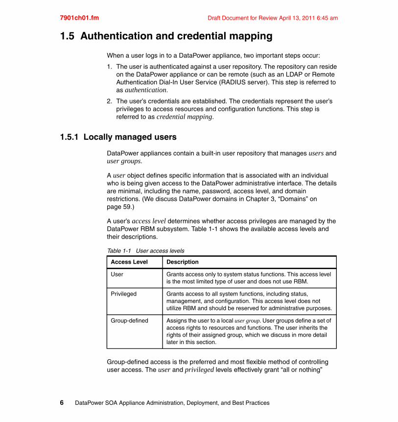
A user’s access level determines whether access privileges are managed by the DataPower RBM subsystem. Table 1-1 shows the available access levels and their descriptions.
Table 1-1 User access levels
Group-defined access is the preferred and most flexible method of controlling user access. The user and privileged levels effectively grant “all or nothing”
Access Level Description
User Grants access only to system status functions. This access level is the most limited type of user and does not use RBM.
Privileged Grants access to all system functions, including status, management, and configuration. This access level does not utilize RBM and should be reserved for administrative purposes.
Group-defined Assigns the user to a local user group. User groups define a set of access rights to resources and functions. The user inherits the rights of their assigned group, which we discuss in more detail later in this section.
6 DataPower SOA Appliance Administration, Deployment, and Best Practices
Draft Document for Review April 13, 2011 6:45 am 7901ch01.fm
access to the device and should be used sparingly if at all. Privileged users are effectively administrators.
1.5.2 Locally-defined user groups
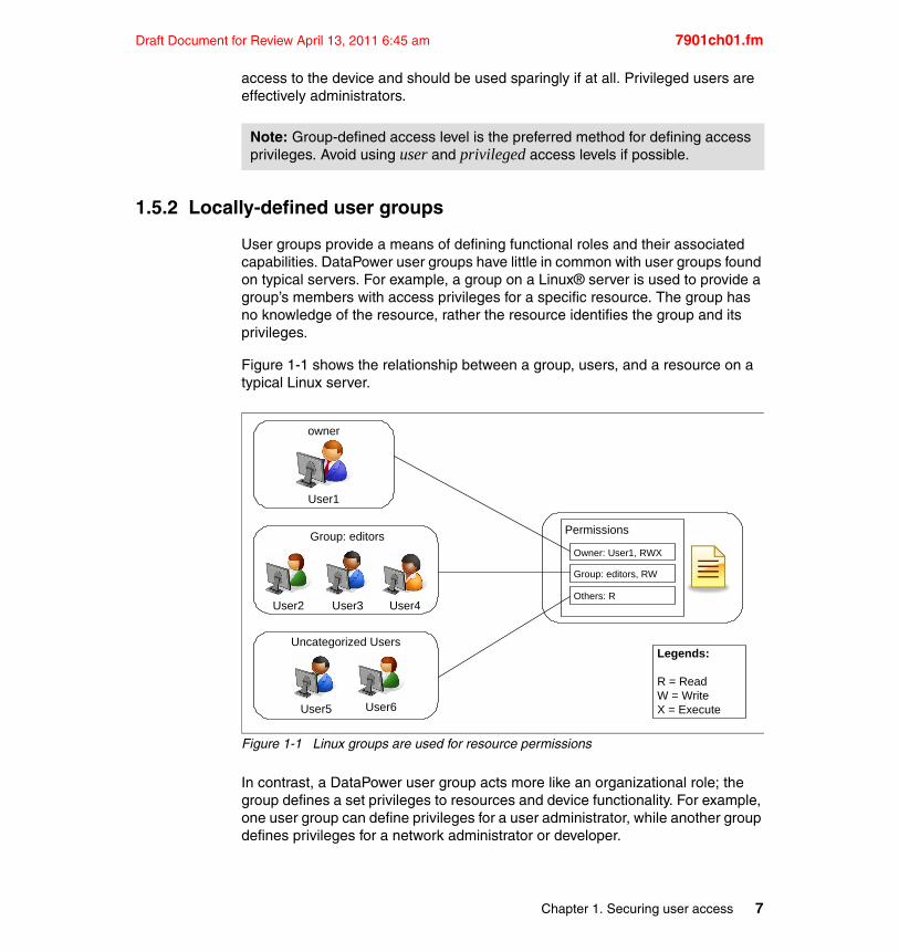
User groups provide a means of defining functional roles and their associated capabilities. DataPower user groups have little in common with user groups found on typical servers. For example, a group on a Linux® server is used to provide a group’s members with access privileges for a specific resource. The group has no knowledge of the resource, rather the resource identifies the group and its privileges.
Figure 1-1 shows the relationship between a group, users, and a resource on a typical Linux server.
Figure 1-1 Linux groups are used for resource permissions
In contrast, a DataPower user group acts more like an organizational role; the group defines a set privileges to resources and device functionality. For example, one user group can define privileges for a user administrator, while another group defines privileges for a network administrator or developer.
Note: Group-defined access level is the preferred method for defining access privileges. Avoid using user and privileged access levels if possible.
owner
Uncategorized Users
User1
User6User5
Group: editors
User2 User4User3
Legends:
R = ReadW = WriteX = Execute
Permissions
Owner: User1, RWX
Group: editors, RW
Others: R
Chapter 1. Securing user access 7
7901ch01.fm Draft Document for Review April 13, 2011 6:45 am
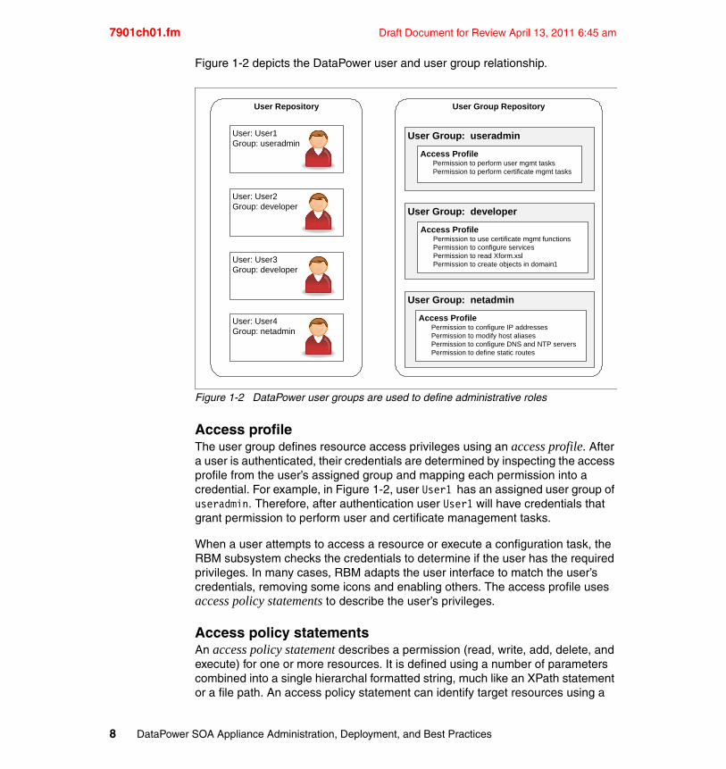
Figure 1-2 depicts the DataPower user and user group relationship.
Figure 1-2 DataPower user groups are used to define administrative roles
Access profileThe user group defines resource access privileges using an access profile. After a user is authenticated, their credentials are determined by inspecting the access profile from the user’s assigned group and mapping each permission into a credential. For example, in Figure 1-2, user User1 has an assigned user group of useradmin. Therefore, after authentication user User1 will have credentials that grant permission to perform user and certificate management tasks.
When a user attempts to access a resource or execute a configuration task, the RBM subsystem checks the credentials to determine if the user has the required privileges. In many cases, RBM adapts the user interface to match the user’s credentials, removing some icons and enabling others. The access profile uses access policy statements to describe the user’s privileges.
Access policy statementsAn access policy statement describes a permission (read, write, add, delete, and execute) for one or more resources. It is defined using a number of parameters combined into a single hierarchal formatted string, much like an XPath statement or a file path. An access policy statement can identify target resources using a
User Repository
User: User1Group: useradmin
User: User2Group: developer
User: User3Group: developer
User: User4Group: netadmin
User Group Repository
User Group: useradmin
Access ProfilePermission to perform user mgmt tasksPermission to perform certificate mgmt tasks
User Group: netadmin
User Group: developer
Access ProfilePermission to use certificate mgmt functionsPermission to configure servicesPermission to read Xform.xslPermission to create objects in domain1
Access ProfilePermission to configure IP addressesPermission to modify host aliasesPermission to configure DNS and NTP serversPermission to define static routes
8 DataPower SOA Appliance Administration, Deployment, and Best Practices
Draft Document for Review April 13, 2011 6:45 am 7901ch01.fm
Perl-compatible regular expression (PCRE), enabling it to identify a single resource or a group of resources that match the specified pattern.
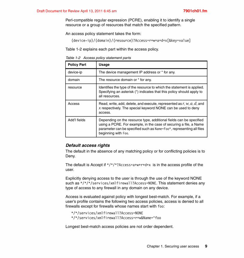
An access policy statement takes the form:
(device-ip)/(domain)/(resource)?Access=r+w+a+d+x[&key=value]
Table 1-2 explains each part within the access policy.
Table 1-2 Access policy statement parts
Default access rightsThe default in the absence of any matching policy or for conflicting policies is to Deny.
The default is Accept if */*/*?Access=a+w+r+d+x is in the access profile of the user.
Explicitly denying access to the user is through the use of the keyword NONE such as */*/*/services/xmlfirewall?Access=NONE. This statement denies any type of access to any firewall in any domain on any device.
Access is evaluated against policy with longest best-match. For example, if a user’s profile contains the following two access policies, access is denied to all firewalls except for firewalls whose names start with foo:
*/*/services/xmlfirewall?Access=NONE*/*/services/xmlfirewall?Access=r+w&Name=^foo
Longest best-match access policies are not order dependent.
Policy Part Usage
device-ip The device management IP address or * for any.
domain The resource domain or * for any.
resource Identifies the type of the resource to which the statement is applied. Specifying an asterisk (*) indicates that this policy should apply to all resources.
Access Read, write, add, delete, and execute, represented as r, w, a, d, and x respectively. The special keyword NONE can be used to deny access.
Add’l fields Depending on the resource type, additional fields can be specified using a PCRE. For example, in the case of securing a file, a Name parameter can be specified such as Name=Foo*, representing all files beginning with Foo.
Chapter 1. Securing user access 9
7901ch01.fm Draft Document for Review April 13, 2011 6:45 am
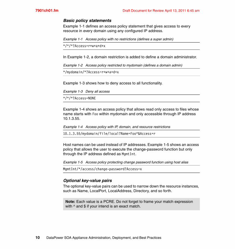
Basic policy statementsExample 1-1 defines an access policy statement that gives access to every resource in every domain using any configured IP address.
Example 1-1 Access policy with no restrictions (defines a super admin)
*/*/*?Access=r+w+a+d+x
In Example 1-2, a domain restriction is added to define a domain administrator.
Example 1-2 Access policy restricted to mydomain (defines a domain admin)
*/mydomain/*?Access=r+w+a+d+x
Example 1-3 shows how to deny access to all functionality.
Example 1-3 Deny all access
*/*/*?Access=NONE
Example 1-4 shows an access policy that allows read only access to files whose name starts with Foo within mydomain and only accessible through IP address 10.1.3.55.
Example 1-4 Access policy with IP, domain, and resource restrictions
10.1.3.55/mydomain/file/local?Name=Foo*&Access=r
Host names can be used instead of IP addresses. Example 1-5 shows an access policy that allows the user to execute the change-password function but only through the IP address defined as MgmtInt.
Example 1-5 Access policy protecting change password function using host alias
MgmtInt/*/access/change-password?Access=x
Optional key-value pairsThe optional key-value pairs can be used to narrow down the resource instances, such as Name, LocalPort, LocalAddress, Directory, and so forth.
Note: Each value is a PCRE. Do not forget to frame your match expression with ^ and $ if your intend is an exact match.
10 DataPower SOA Appliance Administration, Deployment, and Best Practices
Draft Document for Review April 13, 2011 6:45 am 7901ch01.fm
RBM controls access through both the WebGUI and SOMA. Login privilege to either one can be granted separately. Example 1-6 shows an access policy that grants login to web-mgmt only.
Example 1-6 Policy statement that grants access to login for web-mgmt only.
*/*/login/web-mgmt&Access=x
Complex policy statementsExample 1-7 shows how to give a user explicit access to create/modify XML Firewalls with names starting with somePrefix_ and that use local addresses between 10.0.28.0-10.0.28.5 with ports between 5000-5499 within someDomain.
Example 1-7 Complex policy statement using PCRE
*/someDomain/services/xmlfirewall?Name=^somePrefix_.*&LocalAddress=10.0.28.[0-4]&LocalPort=5[0-4][0-9][0-9]&Access=r+w+a+d+x
Example 1-8 gives a user read only access to any file within directories with prefix someOtherPrefix_ and read/write access to any file with prefix somePrefix_.
Example 1-8 Policy statements that limit access to files and directories
*/someDomain/file/local?&Directory=^someOtherPrefix_.*&Access=r*/someDomain/file/local?&Directory=^someOtherPrefix_.*&Filename=^somePrefix_.*&Access=r+w
Every configuration option and every resource can be protected using access policy statements such as those shown in these examples.
Policy statement editorThe basic layout of a policy statement is straightforward and easy to understand; however, knowing the wide range of resource and parameter options is much more difficult to grasp. A visual policy statement editor makes this task much less daunting.
The policy statement editor is available when creating or modifying a user group. The Access Profile section has a Build button that opens the policy statement editor. The smart editor provides drop-down lists of resource types and adjusts the fields and options based on user selections.
Chapter 1. Securing user access 11
7901ch01.fm Draft Document for Review April 13, 2011 6:45 am
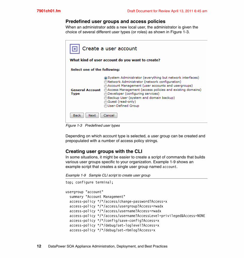
Predefined user groups and access policiesWhen an administrator adds a new local user, the administrator is given the choice of several different user types (or roles) as shown in Figure 1-3.
Figure 1-3 Predefined user types
Depending on which account type is selected, a user group can be created and prepopulated with a number of access policy strings.
Creating user groups with the CLIIn some situations, it might be easier to create a script of commands that builds various user groups specific to your organization. Example 1-9 shows an example script that creates a single user group named account.
Example 1-9 Sample CLI script to create user group
top; configure terminal;
usergroup "account" summary "Account Management" access-policy */*/access/change-password?Access=x access-policy */*/access/usergroup?Access=rwadx access-policy */*/access/username?Access=rwadx access-policy */*/access/username?AccessLevel=privileged&Access=NONE access-policy */*/config/save-config?Access=x access-policy */*/debug/set-loglevel?Access=x access-policy */*/debug/set-rbmlog?Access=x
12 DataPower SOA Appliance Administration, Deployment, and Best Practices

Draft Document for Review April 13, 2011 6:45 am 7901ch01.fm
access-policy */*/login/ssh?Access=x access-policy */*/login/telnet?Access=x access-policy */*/login/web-mgmt?Access=xexit
exit
A sample script for creating the roles shown in Figure 1-3 can be downloaded as part of this book and is named createUserGroups.txt. Refer to Appendix B, “Additional material” on page 247 for information on how to download the file. To execute a CLI script like this, upload the file to the local: directory and use the CLI exec command:
exec local:///createUserGroups.txt
1.5.3 Using local user repository for contingency
Local users and user groups are convenient and easy to setup. However, it is common to employ the use of an external authentication server to facilitate centralized user management. Relying solely on an external authentication server can result in difficulties accessing the administrative interfaces in the event that the external authentication server becomes unresponsive or unreachable. In this case, the local user repository can be used as a backup to authenticate users. We discuss remote user repositories later in 1.5.6, “Remote authentication servers”.
1.5.4 Pros and cons of using the local user repository
Although the local user repository is easy to use and can accommodate nearly all authentication and authorization requirements, it is not always the most appropriate for all situations. The following list of pros and cons can help establish its acceptability in a given environment.
� Pros
– Easy to manage users and groups through the WebGUI and CLI.
– Visual editor for creating and updating access profiles and policy statements.
– Built-in templates for creating commonly used groups such as developers, network administrators, and so on.
– Reliable and not prone to typographical errors.
– Users and groups can be included in device backups.
Chapter 1. Securing user access 13
7901ch01.fm Draft Document for Review April 13, 2011 6:45 am
– Reduces network traffic. All authentication and permissioning occur locally on the appliance.
� Cons
– No capability to federate local users to other DataPower appliances.
– Users cannot be centrally managed.
1.5.5 RBM policy files
As an alternative to using the DataPower built-in user repository, you can use an RBM policy file to define users and their associated privileges. A Role-Based Management (RBM) policy file is an XML document that contains user authentication and credential details. You can find an example RBM policy file in the DataPower file system at store:///RBMinfo.xml.
RBM policy file creation wizardRBM policy files are XML files and, therefore, are generally created and maintained using an XML editor. However, an easy-to-use wizard can also be used to create the initial policy file. The wizard guides the user through a series of dialog boxes, ultimately resulting in a well-formed RBM policy file. The wizard is invoked by clicking the plus sign (+) next to the field where the RBM policy file name is entered.
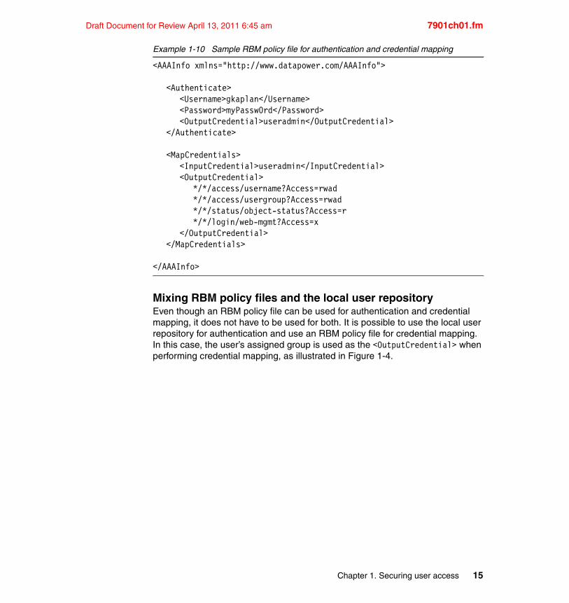
Using an RBM policy file for authenticationAn RBM policy file defines authentication details using <Authenticate> elements. During authentication, RBM searches the RBM policy file for an <Authenticate> element that contains <Username> and <Password> values that match the user name and password that are provided by the user. If found, it saves the value from the <OutputCredential> element and considers the user to be authenticated. The saved value is then used as the input credential for the subsequent credential mapping step.
In Example 1-10, the user name gkaplan is authenticated, and the credential is useradmin.
Using an RBM policy file for credential mappingRBM policy files define credential mapping details using <MapCredentials> elements. RBM searches for a <MapCredentials> element that contains an <InputCredential> matching the saved input credential (from authentication). The value of the <OutputCredential> element becomes the new credential. In Example 1-10, the credential useradmin is mapped to a new set of credentials.
14 DataPower SOA Appliance Administration, Deployment, and Best Practices
Draft Document for Review April 13, 2011 6:45 am 7901ch01.fm
Example 1-10 Sample RBM policy file for authentication and credential mapping
<AAAInfo xmlns="http://www.datapower.com/AAAInfo">
<Authenticate><Username>gkaplan</Username><Password>myPassw0rd</Password><OutputCredential>useradmin</OutputCredential>
</Authenticate>
<MapCredentials><InputCredential>useradmin</InputCredential><OutputCredential>
*/*/access/username?Access=rwad*/*/access/usergroup?Access=rwad*/*/status/object-status?Access=r*/*/login/web-mgmt?Access=x
</OutputCredential></MapCredentials>
</AAAInfo>
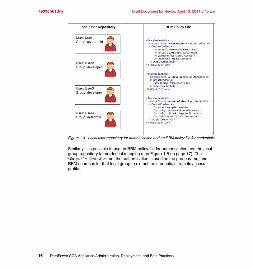
Mixing RBM policy files and the local user repositoryEven though an RBM policy file can be used for authentication and credential mapping, it does not have to be used for both. It is possible to use the local user repository for authentication and use an RBM policy file for credential mapping. In this case, the user’s assigned group is used as the <OutputCredential> when performing credential mapping, as illustrated in Figure 1-4.
Chapter 1. Securing user access 15
7901ch01.fm Draft Document for Review April 13, 2011 6:45 am
Figure 1-4 Local user repository for authentication and an RBM policy file for credentials
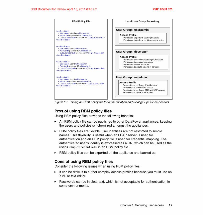
Similarly, it is possible to use an RBM policy file for authentication and the local group repository for credential mapping (see Figure 1-5 on page 17). The <OutputCredential> from the authentication is used as the group name, and RBM searches for that local group to extract the credentials from its access profile.
Local User Repository
User: User1Group: useradmin
User: User2Group: developer
User: User3Group: developer
User: User4Group: netadmin
RBM Policy File
< MapCredentials> < InputCredential> useradmin< / InputCredent ial> < OutputCredent ial> */ */ access/ username?Access= rwad */ */ access/ usergroup?Access= rwad */ */ status/ object- status?Access= r */ */ login/ web- mgmt?Access= x < / OutputCredential>< / MapCredent ials>
< MapCredentials> < InputCredential> developer< / InputCredential> < OutputCredent ial> */ devdomain/ *?Access= rwadx < / OutputCredential>< / MapCredent ials>
< MapCredentials> < InputCredential> netadmin< / InputCredential> < OutputCredent ial> */ */ access/ snmp?Access= rw */ */ conf ig/ remove- chkpoint?Access= x */ */ conf ig/ rollback- chkpoint?Access= x */ */ conf ig/ save- chkpoint?Access= x < / OutputCredential>< / MapCredent ials>
16 DataPower SOA Appliance Administration, Deployment, and Best Practices
Draft Document for Review April 13, 2011 6:45 am 7901ch01.fm
Figure 1-5 Using an RBM policy file for authentication and local groups for credentials
Pros of using RBM policy filesUsing RBM policy files provides the following benefits:
� An RBM policy file can be published to other DataPower appliances, keeping the users and policies synchronized amongst the appliances.
� RBM policy files are flexible; user identities are not restricted to simple names. This flexibility is useful when an LDAP server is used for authentication and an RBM policy file is used for credential mapping. The authenticated user’s identity is expressed as a DN, which can be used as the user’s <InputCredential> in an RBM policy file.
� RBM policy files can be exported off the appliance and backed up.
Cons of using RBM policy filesConsider the following issues when using RBM policy files:
� It can be difficult to author complex access profiles because you must use an XML or text editor.
� Passwords can be in clear text, which is not acceptable for authentication in some environments.
Local User Group Repository
User Group: useradmin
Access ProfilePermission to perform user mgmt tasksPermission to perform certificate mgmt tasks
User Group: netadmin
User Group: developer
Access ProfilePermission to use certificate mgmt functionsPermission to configure servicesPermission to read Xform.xslPermission to create objects in domain1
Access ProfilePermission to configure IP addressesPermission to modify host aliasesPermission to configure DNS and NTP serversPermission to define static routes
RBM Policy File
< Authent icate> < Username> gkaplan< / Username> < Password> myPassword< / Password> < OutputCredent ial> useradmin< / OutputCredent ial>< / Authenticate>
< Authent icate> < Username> user1< / Username> < Password> password1< / Password> < OutputCredent ial> developer< / OutputCredential>< / Authenticate>
< Authent icate> < Username> user2< / Username> < Password> password2< / Password> < OutputCredent ial> developer< / OutputCredential>< / Authenticate>
< Authent icate> < Username> user3< / Username> < Password> password3< / Password> < OutputCredent ial> netadmin< / OutputCredent ial>< / Authenticate>
Chapter 1. Securing user access 17
7901ch01.fm Draft Document for Review April 13, 2011 6:45 am
� The policy files are not centralized. RBM files can be published from one device to another, but no real “user management” function exists to maintain users and policies within the file.
1.5.6 Remote authentication servers
In many organizations, user authentication is frequently carried out remotely using an LDAP server, RADIUS server, or even a mainframe. DataPower appliances support three commonly used remote authentication servers:
� LDAP server� RADIUS servers� System Authorization Facility (SAF)
In situations where an unsupported, in-house or proprietary authentication server must be used, a custom XSLT can be written to accommodate it.
Remote user management is a good idea but only provides half of the login processing requirements. The user’s access credentials must still be determined.
There are a number of options that can be used to establish credentials for remotely authenticated users:
� A local user group� A Role-Based Management (RBM) policy file� A custom developed mapping solution written in XSL
Remotely defined LDAP groupsRemote authentication servers generally do not return the user’s group membership details. For example, after LDAP authentication, the returned credential is the user’s fully qualified DN. That DN provides no insight into what groups the user might belong. For this reason, it might be necessary to configure a second LDAP query to determine the user’s group.
Configuring the LDAP query to retrieve the user’s group is straightforward and is accomplished by enabling Search LDAP for Group Name in the RBM Credentials configuration page (Administration RBM Settings Credential tab). The following configuration scenarios provide more details on using LDAP groups.
Note: RBM only supports a user belonging to one group. If the results of an LDAP query yield multiple groups, only the first returned group is recognized. This limitation can be overcome using a custom stylesheet, as discussed in “Custom credential mapping” on page 21.
18 DataPower SOA Appliance Administration, Deployment, and Best Practices
Draft Document for Review April 13, 2011 6:45 am 7901ch01.fm
Local user group for credential mappingIn this scenario, a user is first authenticated using one of the supported authentication mechanisms such as LDAP. The result of the authentication is typically the user’s credential in the form of either a user name, qualified DN, or some other proprietary format. The group cannot be determined by this credential and therefore needs to be further mapped to a local group. A remote LDAP server can be queried to discover of which group the user is a member.
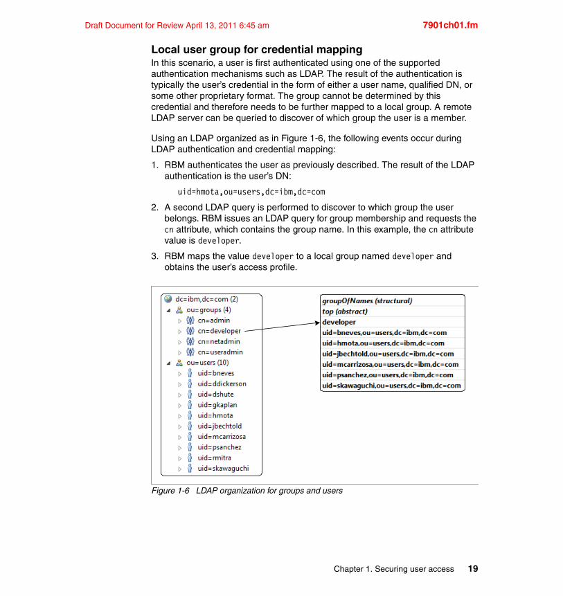
Using an LDAP organized as in Figure 1-6, the following events occur during LDAP authentication and credential mapping:
1. RBM authenticates the user as previously described. The result of the LDAP authentication is the user’s DN:
uid=hmota,ou=users,dc=ibm,dc=com
2. A second LDAP query is performed to discover to which group the user belongs. RBM issues an LDAP query for group membership and requests the cn attribute, which contains the group name. In this example, the cn attribute value is developer.
3. RBM maps the value developer to a local group named developer and obtains the user’s access profile.
Figure 1-6 LDAP organization for groups and users
Chapter 1. Securing user access 19
7901ch01.fm Draft Document for Review April 13, 2011 6:45 am
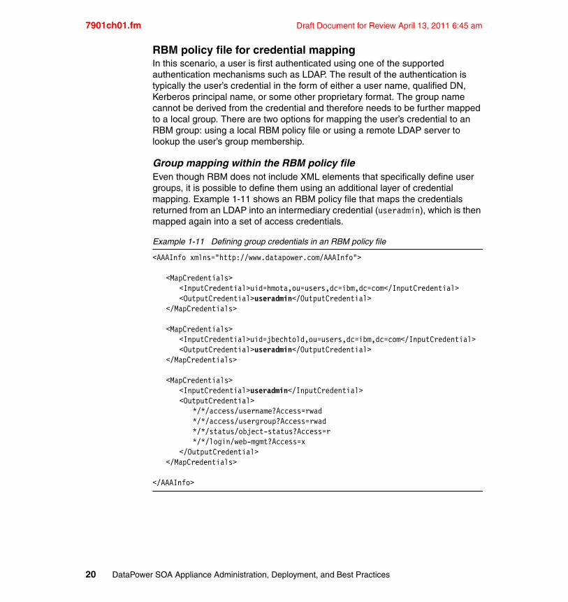
RBM policy file for credential mappingIn this scenario, a user is first authenticated using one of the supported authentication mechanisms such as LDAP. The result of the authentication is typically the user’s credential in the form of either a user name, qualified DN, Kerberos principal name, or some other proprietary format. The group name cannot be derived from the credential and therefore needs to be further mapped to a local group. There are two options for mapping the user’s credential to an RBM group: using a local RBM policy file or using a remote LDAP server to lookup the user’s group membership.
Group mapping within the RBM policy fileEven though RBM does not include XML elements that specifically define user groups, it is possible to define them using an additional layer of credential mapping. Example 1-11 shows an RBM policy file that maps the credentials returned from an LDAP into an intermediary credential (useradmin), which is then mapped again into a set of access credentials.
Example 1-11 Defining group credentials in an RBM policy file
<AAAInfo xmlns="http://www.datapower.com/AAAInfo">
<MapCredentials><InputCredential>uid=hmota,ou=users,dc=ibm,dc=com</InputCredential><OutputCredential>useradmin</OutputCredential>
</MapCredentials>
<MapCredentials><InputCredential>uid=jbechtold,ou=users,dc=ibm,dc=com</InputCredential><OutputCredential>useradmin</OutputCredential>
</MapCredentials>
<MapCredentials><InputCredential>useradmin</InputCredential><OutputCredential>
*/*/access/username?Access=rwad*/*/access/usergroup?Access=rwad*/*/status/object-status?Access=r*/*/login/web-mgmt?Access=x
</OutputCredential></MapCredentials>
</AAAInfo>
20 DataPower SOA Appliance Administration, Deployment, and Best Practices
Draft Document for Review April 13, 2011 6:45 am 7901ch01.fm
LDAP group mappingOptionally, an LDAP server can be queried to determine group membership before attempting to establish access credentials. In this case, the following steps occur:
1. RBM authenticates the user as previously described. The results of the authentication are the user’s credential.
2. A second LDAP query is performed to discover the user’s group membership. The group name is returned as an LDAP attribute value.
3. The RBM policy file is then searched for an <InputCredential> that matches the group name from step 2. If found, the contents of the <OutputCredential> becomes the user’s new credentials.
Custom credential mappingIn this scenario, the results of the authentication step are used as the input context into an XSL transformation (see Example 1-12). The XSL template is responsible for interpreting the credential and writing the user’s access credentials to the output context. Example 1-13 shows the basic structure of a custom XSLT for mapping credentials.
Example 1-12 Input context for custom credential mapping XSLT
<credentials><entry>user credential goes here</entry>
</credentials>
Example 1-13 Sample custom XSLT for mapping credentials
<xsl:template match="/"><xsl:variable name="credential" select="/credentials/entry"/><xsl:choose>
<xsl:when test="$credential = 'david'">*/*/access/username?Access=rwad*/*/access/usergroup?Access=rwad*/*/status/object-status?Access=r*/*/login/web-mgmt?Access=x
</xsl:when><xsl:when test="$credential = 'bruno'">
*/*/*?Access=rwadx
Note: A custom XSLT can use any of DataPower’s extension functions, including LDAP query functions, SQL functions, and communications functions, to name a few. Practically any mapping scenario can be supported using a custom stylesheet.
Chapter 1. Securing user access 21
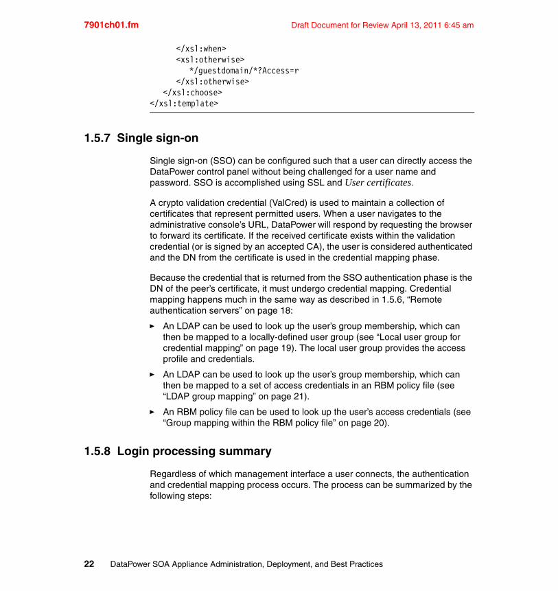
7901ch01.fm Draft Document for Review April 13, 2011 6:45 am
</xsl:when><xsl:otherwise>
*/guestdomain/*?Access=r</xsl:otherwise>
</xsl:choose></xsl:template>
1.5.7 Single sign-on
Single sign-on (SSO) can be configured such that a user can directly access the DataPower control panel without being challenged for a user name and password. SSO is accomplished using SSL and User certificates.
A crypto validation credential (ValCred) is used to maintain a collection of certificates that represent permitted users. When a user navigates to the administrative console’s URL, DataPower will respond by requesting the browser to forward its certificate. If the received certificate exists within the validation credential (or is signed by an accepted CA), the user is considered authenticated and the DN from the certificate is used in the credential mapping phase.
Because the credential that is returned from the SSO authentication phase is the DN of the peer’s certificate, it must undergo credential mapping. Credential mapping happens much in the same way as described in 1.5.6, “Remote authentication servers” on page 18:
� An LDAP can be used to look up the user’s group membership, which can then be mapped to a locally-defined user group (see “Local user group for credential mapping” on page 19). The local user group provides the access profile and credentials.
� An LDAP can be used to look up the user’s group membership, which can then be mapped to a set of access credentials in an RBM policy file (see “LDAP group mapping” on page 21).
� An RBM policy file can be used to look up the user’s access credentials (see “Group mapping within the RBM policy file” on page 20).
1.5.8 Login processing summary
Regardless of which management interface a user connects, the authentication and credential mapping process occurs. The process can be summarized by the following steps:
22 DataPower SOA Appliance Administration, Deployment, and Best Practices
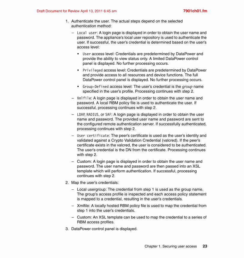
Draft Document for Review April 13, 2011 6:45 am 7901ch01.fm
1. Authenticate the user. The actual steps depend on the selected authentication method:
– Local user: A login page is displayed in order to obtain the user name and password. The appliance’s local user repository is used to authenticate the user. If successful, the user’s credential is determined based on the user’s access level:
• User access level: Credentials are predetermined by DataPower and provide the ability to view status only. A limited DataPower control panel is displayed. No further processing occurs.
• Privileged access level: Credentials are predetermined by DataPower and provide access to all resources and device functions. The full DataPower control panel is displayed. No further processing occurs.
• Group-Defined access level: The user’s credential is the group name specified in the user’s profile. Processing continues with step 2.
– Xmlfile: A login page is displayed in order to obtain the user name and password. A local RBM policy file is used to authenticate the user. If successful, processing continues with step 2.
– LDAP, RADIUS, or SAF: A login page is displayed in order to obtain the user name and password. The provided user name and password are sent to the configured remote authentication server. If successfully authenticated, processing continues with step 2.
– User certificate: The peer’s certificate is used as the user’s identity and validated against a Crypto Validation Credential (valcred). If the peer’s certificate exists in the valcred, the user is considered to be authenticated. The user’s credential is the DN from the certificate. Processing continues with step 2.
– Custom: A login page is displayed in order to obtain the user name and password. The user name and password are then passed into an XSL template which will perform authentication. If successful, processing continues with step 2.
2. Map the user’s credentials:
– Local usergroup: The credential from step 1 is used as the group name. The group’s access profile is inspected and each access policy statement is mapped to a credential, resulting in the user’s credentials.
– Xmlfile: A locally hosted RBM policy file is used to map the credential from step 1 into the user’s credentials.
– Custom: An XSL template can be used to map the credential to a series of RBM access profiles.
3. DataPower control panel is displayed.
Chapter 1. Securing user access 23
7901ch01.fm Draft Document for Review April 13, 2011 6:45 am
1.6 Audit logs
Audit logs provide a history of all administrative activities that occur on the appliance. The audit log is separate from the regular DataPower logs and can be viewed from the navigation menu under Status View Logs Audit Log.
Monitoring audit logs is important in assuring the safety and reliability of a DataPower appliance, which can be accomplished in several ways:
� Audit event subscription where a log target can be created that subscribes to audit events.
� Copying the audit log off the appliance using either CLI or SOMA
1.6.1 Obtaining the audit log using CLI
The CLI can be used to copy the audit log to another location or send it to a mail recipient.
Example 1-14 shows the CLI command to copy the audit log to a new file in the temporary: directory.
Example 1-14 CLI command to copy audit log to the temporary: directory
copy audit:///audit-log temporary:///audit-log
Example 1-15 shows the CLI command to copy the audit log to an HTTP file server URL.
Example 1-15 CLI command to copy audit log to an HTTP file server
copy audit:///audit-log <HTTP File Server-URL>
Example 1-16 shows the CLI command to send the audit log to a mail recipient using an SMTP server.
Example 1-16 CLI command to send the audit log to a mail recipient.
send file audit:///audit-log <outgoing-mail-server> <email-address>
1.6.2 Copying the audit log using SOMA
The audit log can be retrieved using DataPower’s SOAP management interface (SOMA). Example 1-17 on page 25 shows a SOMA request that retrieves the audit log.
24 DataPower SOA Appliance Administration, Deployment, and Best Practices
Draft Document for Review April 13, 2011 6:45 am 7901ch01.fm
Example 1-17 SOMA request to obtain the audit log
<?xml version="1.0" encoding="UTF-8"?><soapenv:Envelope xmlns:soapenv="http://sc...omitted...envelope/">
<soapenv:Body><dp:request domain="default" xmlns:dp="ht...omitted...anagement"> <dp:get-file name="audit:///audit-log"/></dp:request>
</soapenv:Body></soapenv:Envelope>
The SOMA response will contain the base64 encoded contents of the audit log and therefore will require decoding.
For more information on SOMA, please refer to 10.3.3, “SOAP Management Interface (SOMA)” on page 225.
1.7 Best practices
As with any complex highly-configurable device, there are some ways of accomplishing certain tasks that are better than others. This section provides a basic list of tips and recommendations that have, in most circumstances, proven to be “best practices.” That said, they are not laws and might not be the best solutions in all situations.
� Capture audit logs. Audit logs provide a window into what administrative activities have occurred on the appliance. Audit logs can be sent to DataPower log targets for transmission to a variety of log servers. See 1.6, “Audit logs” on page 24.
� Configure an inactivity timeout for WebGUI. This is found in the navigation menu under Network Management? Web Management Service.
� Change WebGUI Port. The most commonly used port is 9090. Secure environments might considering using a port other than 9090. This is found in the navigation menu under Network Management? Web Management Service.
� Save and protect the admin password. It cannot be recovered. If it becomes misplaced and no backup admin exists, the appliance must be returned to IBM for reinitialization.
� Create a second backup privileged administrative user. This provides an alternate admin (superuser) in the event that the primary one becomes inaccessible. An alternate admin user can reset the password of the primary admin if necessary.
Chapter 1. Securing user access 25
7901ch01.fm Draft Document for Review April 13, 2011 6:45 am
� Use Group-Defined access level instead of User or Privileged when creating local users (this does not apply when using remote authentication servers). The user access level grants the ability to view status only, and the privileged access level provides complete access to the appliance. Group-defined utilizes DataPower’s Role-Based Management functionality which is more flexible.
� Enable Local Login as Fallback when configuring an appliance for non-Local RBM authentication. In the event that a remote authentication server becomes inaccessible, the local user repository can be used as a backup way of entry. It might not be necessary to replicate all users, rather just a few for contingency purposes.
� Consider restricting administrative logon to the serial port. This is not a best practice, but rather a consideration point. Government agencies might require that administrative access be restricted to the serial port only.
� Use RBM for CLI access control, not CLI Command Groups. CLI command groups are deprecated and do not provide robust access control like RBM does.
� Do not use DHCP assigned IP addresses in ACLs. DHCP assigned client addresses can change, resulting in inaccessibility to the appliance.
� Adjust authentication caching to provide maximum permissible lifetime. Disabled or low caching lifetimes can result in increased network traffic.
1.8 Troubleshooting
Implementing administrative configurations that rely on remote authentication servers, RBM policy files, or custom development might require a certain amount of troubleshooting before all of the pieces are properly integrated. Care should be taken to assure that the configuration steps do not inadvertently prevent access to the appliance.
� When testing or troubleshooting RBM, make sure to enable RBM debug logging. This is found in the Troubleshooting panel in the Logging section. Log messages might appear in either the regular system logs or the audit logs.
� Verify that remote authentication servers are reachable from DataPower. Use the Ping Remote and TCP Connection Test to assure the servers are accessible.
� Assure that any DNS server settings are properly configured.
� Assure that the appliance’s time is accurate and that any NTP server connections are working. Incorrect date settings could affect the validity of some certificates.
26 DataPower SOA Appliance Administration, Deployment, and Best Practices
Draft Document for Review April 13, 2011 6:45 am 7901ch01.fm
� If a device becomes inaccessible due to access control list violations, you might be able to verify what IP addresses are in them using either the command line interface or by inspecting a previous backup.
� Only secure one administrative interface during security configuration. In other words, if you’re setting up security on the WebGUI, leave the CLI unsecured until everything has been verified. This allows for a “back door” in case the WebGUI becomes inaccessible.
Note: Make sure to always enable local users as fallback when making changes to RBM and user management settings. This enables the users in the local repository to remain active in the event remote authentication servers or custom stylesheets fail to operate as expected.
Chapter 1. Securing user access 27

7901ch01.fm Draft Document for Review April 13, 2011 6:45 am
28 DataPower SOA Appliance Administration, Deployment, and Best Practices
Draft Document for Review April 13, 2011 6:45 am 7901ch02.fm
Chapter 2. Networking
At their core, DataPower appliances are highly capable network device and provide a wide array of networking, security, and integration tasks. Whether protecting web services, mediating security tokens, or proxying between disparate wire protocols, all activities rely in some fashion on the underlying network. For this reason, it’s imperative that a DataPower appliance’s network configuration be compatible with its surrounding network environment. Understanding DataPower’s networking capabilities and configuration nuances can help assure maximum processing throughput.
This chapter discusses the considerations and activities associated with IBM WebSphere DataPower SOA Appliance Networking.
2
© Copyright IBM Corp. 2011. All rights reserved. 29
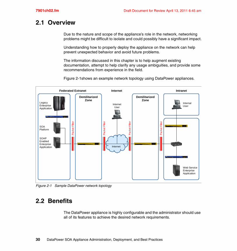
7901ch02.fm Draft Document for Review April 13, 2011 6:45 am
2.1 Overview
Due to the nature and scope of the appliance’s role in the network, networking problems might be difficult to isolate and could possibly have a significant impact.
Understanding how to properly deploy the appliance on the network can help prevent unexpected behavior and avoid future problems.
The information discussed in this chapter is to help augment existing documentation, attempt to help clarify any usage ambiguities, and provide some recommendations from experience in the field.
Figure 2-1shows an example network topology using DataPower appliances.
Figure 2-1 Sample DataPower network topology
2.2 Benefits
The DataPower appliance is highly configurable and the administrator should use all of its features to achieve the desired network requirements.
DemilitarizedZone
DemilitarizedZone
Federated Extranet Internet Intranet
InternetUser
InternalUser
LegacyEnterpriseApplication
SOAPlatform
SOAPEnabledEnterpriseApplication
Web ServiceEnterpriseApplication
Internet
Pa
cket
Filt
er
Pa
cket
Filt
er
Pa
cket
Filt
er
Pa
cket
Filt
er
30 DataPower SOA Appliance Administration, Deployment, and Best Practices
Draft Document for Review April 13, 2011 6:45 am 7901ch02.fm
Each configuration feature should be considered as only a part of the complete network solution. Multiple components need to work together to achieve a proper deployment, including:
� Multiple physical ethernet interfaces
� Virtual LANs to help further segregate traffic on a physical NIC
� IP addresses and routes on ethernet and VLAN interfaces
� Bind addresses on non-polling FSHs and management interfaces
� Network Settings
� Source and Destination routing
� Interface Isolation (off, strict, relaxed)
� Reverse Path Filtering (on/off)
� Access Control Lists (ACLs)
2.3 Usage
This section describes the usage capabilities, configuration settings, and some of the nuances regarding networking with the DataPower appliance.
It is important to correctly set the network interface configuration settings and routing behavior to integrate properly within the network topology and architecture.
The main objective of this section is to help administrators make an informed decision regarding network planning, configuration, and proper deployment.
2.3.1 Network interface configuration and routing
IBM WebSphere DataPower SOA Appliances come with four physical network interfaces and one serial port to communicate with the external world. To start using the appliance, the initialization is done through the serial port for security reasons.
The process to initialize the device is covered in the appliance documentation. This section provides an overview of the main settings to consider when connecting the device to the network.
Chapter 2. Networking 31
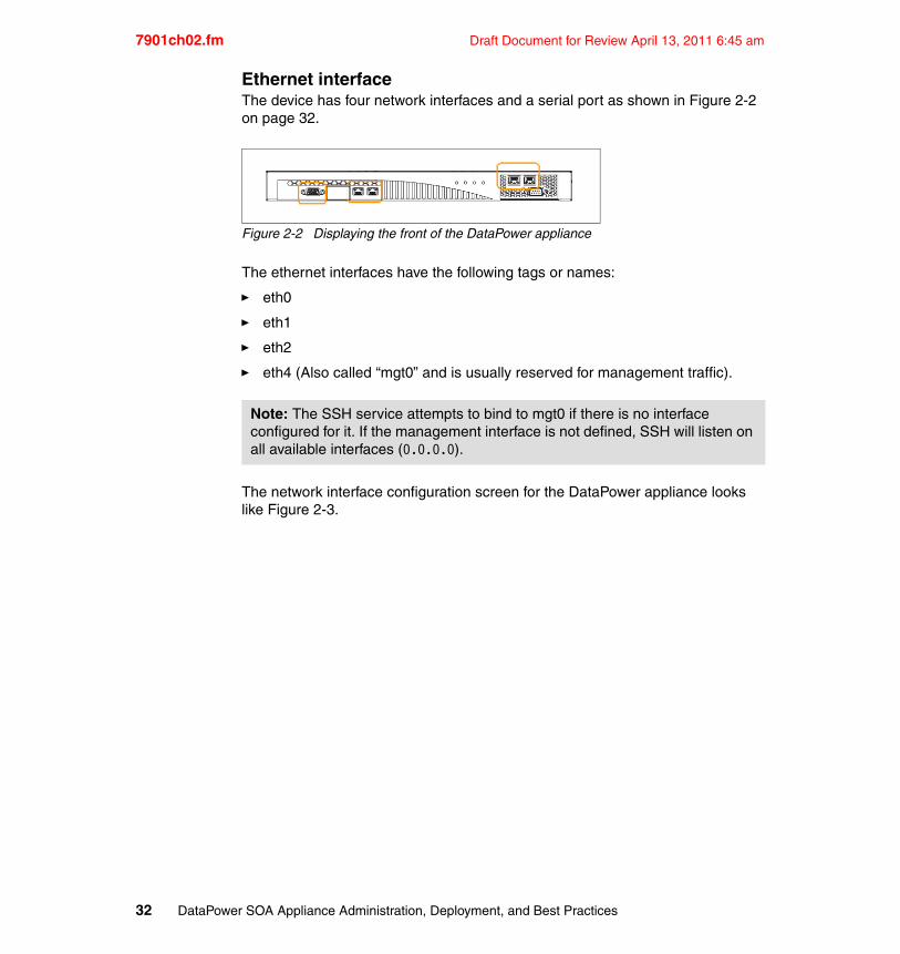
7901ch02.fm Draft Document for Review April 13, 2011 6:45 am
Ethernet interfaceThe device has four network interfaces and a serial port as shown in Figure 2-2 on page 32.
Figure 2-2 Displaying the front of the DataPower appliance
The ethernet interfaces have the following tags or names:
� eth0
� eth1
� eth2
� eth4 (Also called “mgt0” and is usually reserved for management traffic).
The network interface configuration screen for the DataPower appliance looks like Figure 2-3.
Note: The SSH service attempts to bind to mgt0 if there is no interface configured for it. If the management interface is not defined, SSH will listen on all available interfaces (0.0.0.0).
32 DataPower SOA Appliance Administration, Deployment, and Best Practices
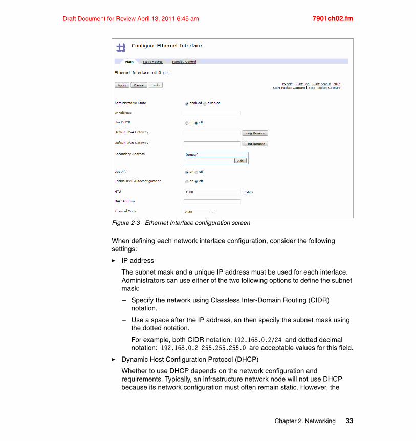
Draft Document for Review April 13, 2011 6:45 am 7901ch02.fm
Figure 2-3 Ethernet Interface configuration screen
When defining each network interface configuration, consider the following settings:
� IP address
The subnet mask and a unique IP address must be used for each interface. Administrators can use either of the two following options to define the subnet mask:
– Specify the network using Classless Inter-Domain Routing (CIDR) notation.
– Use a space after the IP address, an then specify the subnet mask using the dotted notation.
For example, both CIDR notation: 192.168.0.2/24 and dotted decimal notation: 192.168.0.2 255.255.255.0 are acceptable values for this field.
� Dynamic Host Configuration Protocol (DHCP)
Whether to use DHCP depends on the network configuration and requirements. Typically, an infrastructure network node will not use DHCP because its network configuration must often remain static. However, the
Chapter 2. Networking 33
7901ch02.fm Draft Document for Review April 13, 2011 6:45 am
option to lease an IP address for the device is still available through the use of the DHCP setting.
� Default gateway
The default gateway defines the interface and route in which the traffic leaves the appliance when it does not match an explicitly configured static route.
� Secondary address
Each interface can have additional IP addresses in addition to the primary IP address.
� Address Resolution Protocol (ARP)
This is the option to enable or disable ARP, which broadcasts the IP address and the physical interface mapping over the network.
� IPv6
Configure this field only if the network is using IPv6. When enabled, it creates an IPv6 address linked to the primary interface by default.
� Stateless Address Autoconfiguration (SLAAC)
This option is only available when IPv6 is enabled and used to enable or disable SLAAC. When enabled, the IPv6 address is obtained when connected to the network. When disabled, the interface uses the defined primary address.
� Maximum Transmission Unit (MTU)
MTU defines the size of the MAC layer data field that can be handled on this interface. Do not modify this configuration unless all other interfaces on this network are similarly configured. If any VLAN sub-interfaces are enabled, an extra 4 bytes are added automatically.
� MAC address
Use this field to override the assigned MAC address associated with the hardware interface. This field should not be changed arbitrarily from the default.
As a side note, the original MAC address might not be displayed in the interface status provider when the appliance is in the Active State for Standby Control and may only display the Virtual MAC address.
� Physical Mode
Note: All secondary addresses must be on the same subnet as the primary address.
34 DataPower SOA Appliance Administration, Deployment, and Best Practices
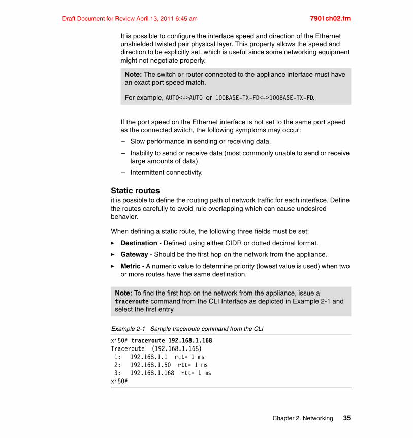
Draft Document for Review April 13, 2011 6:45 am 7901ch02.fm
It is possible to configure the interface speed and direction of the Ethernet unshielded twisted pair physical layer. This property allows the speed and direction to be explicitly set. which is useful since some networking equipment might not negotiate properly.
If the port speed on the Ethernet interface is not set to the same port speed as the connected switch, the following symptoms may occur:
– Slow performance in sending or receiving data.
– Inability to send or receive data (most commonly unable to send or receive large amounts of data).
– Intermittent connectivity.
Static routesit is possible to define the routing path of network traffic for each interface. Define the routes carefully to avoid rule overlapping which can cause undesired behavior.
When defining a static route, the following three fields must be set:
� Destination - Defined using either CIDR or dotted decimal format.
� Gateway - Should be the first hop on the network from the appliance.
� Metric - A numeric value to determine priority (lowest value is used) when two or more routes have the same destination.
Example 2-1 Sample traceroute command from the CLI
xi50# traceroute 192.168.1.168Traceroute (192.168.1.168) 1: 192.168.1.1 rtt= 1 ms 2: 192.168.1.50 rtt= 1 ms 3: 192.168.1.168 rtt= 1 msxi50#
Note: The switch or router connected to the appliance interface must have an exact port speed match.
For example, AUTO<->AUTO or 100BASE-TX-FD<->100BASE-TX-FD.
Note: To find the first hop on the network from the appliance, issue a traceroute command from the CLI Interface as depicted in Example 2-1 and select the first entry.
Chapter 2. Networking 35
7901ch02.fm Draft Document for Review April 13, 2011 6:45 am
2.3.2 VLAN sub-interfaces
Use Virtual LANs (VLANs) to define a set of machines that can communicate with each other as if they were attached to the same physical network. In addition to the regular interface settings, the VLAN sub-interface will need to be associated with a specific physical interface, provide a VLAN Identifier, and specify an Outbound Priority. VLAN sub-interfaces can be defined outside the subnet of the primary interface.
IPv6 default routesIn order to define an IPv6 default route in a VLAN sub-interface, it is necessary to configure the IPv4 as the primary address and the IPv6 entry as a secondary address, then add the IPv4 and the IPv6 default gateways. Once this has been completed, both addresses will be configured on the system and their default routes will appear as expected.
2.3.3 Network settings
This section provides an explanation of the appliance-wide general network settings. These setting can be configured in the Network Settings configuration screen shown in Figure 2-4.
Note: The VLAN sub-interface can be configured to use DHCP, but then it will not allow a static route to be defined for this sub-interface.
If static routes are defined within a VLAN sub-interface using DHCP, the VLAN will drop the IP address and any connectivity to that IP address will be lost.
36 DataPower SOA Appliance Administration, Deployment, and Best Practices
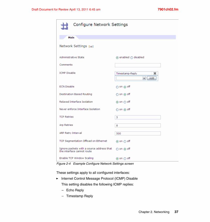
Draft Document for Review April 13, 2011 6:45 am 7901ch02.fm
Figure 2-4 Example Configure Network Settings screen
These settings apply to all configured interfaces:
� Internet Control Message Protocol (ICMP) Disable
This setting disables the following ICMP replies:
– Echo Reply
– Timestamp Reply
Chapter 2. Networking 37
7901ch02.fm Draft Document for Review April 13, 2011 6:45 am
By default, the Timestamp-Reply is disabled for ICMP.
– Info Reply
– Address Mask Reply
This means that by default, the appliance will respond to ICMP pings, Info requests, and Address Mask queries.
� Explicit Congestion Notification (ECN) Disable
ECN is a flag defined to alert about network congestion to other devices. By default, TCP sessions are ECN enabled in the appliance. Some older network devices are not compatible with ECN. If the network is experiencing packet loss, ECN can be disabled to resolve the problem. If the problem persists, this feature should be enabled again.
� Destination Based Routing
This setting controls the behavior of how the appliance routes responding packets to an incoming client request.
The default behavior selects the interface bound to the service IP address. In the case of a service listening on multiple IP addresses (0.0.0.0), the appliance will use the interface that initially received the request (not the interface that is bound to the service that generated the response).
When it is enabled, the interface selection uses the routing table to determine the best path to the client, irrespective of the service or receiving interface.
� Relaxed Interface Isolation
For security reasons, an incoming packet typically will only be accepted when the destination address matches the IP address configured on the ethernet interface. The Relaxed Interface Isolation option allows less strict enforcement so that packets with the destination address within the same subnet may be allowed.
This option should be set to “on” if Destination Based Routing is also on.
� TCP Segmentation Offload on Ethernet
This setting enables an ethernet chip feature intended to improve performance on large TCP writes to the network. Disable this option only if
Note: Destination based routing is for backward compatibility only. Destination based routing should only be enabled if an upgrade disrupts existing connectivity.
38 DataPower SOA Appliance Administration, Deployment, and Best Practices
Draft Document for Review April 13, 2011 6:45 am 7901ch02.fm
link layer resets are seen on the network or to determine if this feature is incompatible with the network traffic.
� Reverse-Path Filtering
The option “Ignore packets with a source address that the interface cannot route” can ignore packets that have a source address which the interface cannot route.
By default, incoming packets with an unreachable source address will still be accepted and processed.
� Enable TCP Window Scaling
This setting allows negotiation of window sizes greater than 64 KB by default. Disable this option when integrating with TCP systems that cannot handle window scaling.
2.3.4 Host alias, static hosts, and DNS
This section explains the usage of host alias and static hosts. It also describes the configuration of DNS servers and the management options.
Host aliasThe host alias may be used in place of IP addresses for object configuration and are often used to simplify export and import of service configurations between DataPower systems.
Static hostThe static host setting manually maps a host name to the host IP address without using DNS. This can be useful if DNS is not available, incorrect, or incomplete. However, the device's DNS name resolver uses a cache, therefore static mappings will usually not result in significant performance improvement.
Domain Name Server (DNS)The DNS section is where the list of DNS Servers and Search Domains are configured.
If a port is not configured, the appliance uses port 53 by default (for both UDP and TCP).
Note: An appliance restart is required when modifying TCP Segmentation Offload in order for the change to take effect.
Chapter 2. Networking 39
7901ch02.fm Draft Document for Review April 13, 2011 6:45 am
Selecting the DNS Load Balancing Algorithm controls which DNS server is used when multiple DNS Servers are configured.
There are two Load Balancing algorithms available for DNS servers:
� The First Alive algorithm will use the first available DNS server in the list and then will try subsequent servers in the list if the first DNS server is down. When selected in the WEBGUI, the First Alive algorithm will show a retry and timeout setting for the whole DNS group.
� The Round Robin algorithm will alternate through the list of configured DNS servers. Selecting the Round Robin algorithm only allows each DNS to have its own retry setting.
2.3.5 Routing
The DataPower appliance has several features that affect the network path selected for traffic. Packets responding to incoming traffic typically use the same interface they came in on, however outgoing new TCP connections utilize the routing table to select an outgoing interface.
The routing table shows the routing rules generated from configured static routes and default routes.
It is important to understand that default routes and static routes on the DataPower appliance behave differently and have unique functionality.
A static route forces the DataPower appliance to use a specific interface and a specific set of network hops to access a given set of destinations.
The default route is created by setting the Default Gateway on one of the appliance’s interfaces. The appliance uses a default route when a given destination address is unknown.
When a specific route cannot be found and multiple default routes are configured, the appliance will randomly pick which interface to use for outbound traffic.
For network traffic to follow a specific route, configure a static route instead of relying on a Default Gateway.
Consider Example 2-2, which shows the routing table from the CLI command show route:
Tip: Consider using DNS aliases on a DNS server as an alternative to using secondary IP addresses directly on the appliance.
40 DataPower SOA Appliance Administration, Deployment, and Best Practices
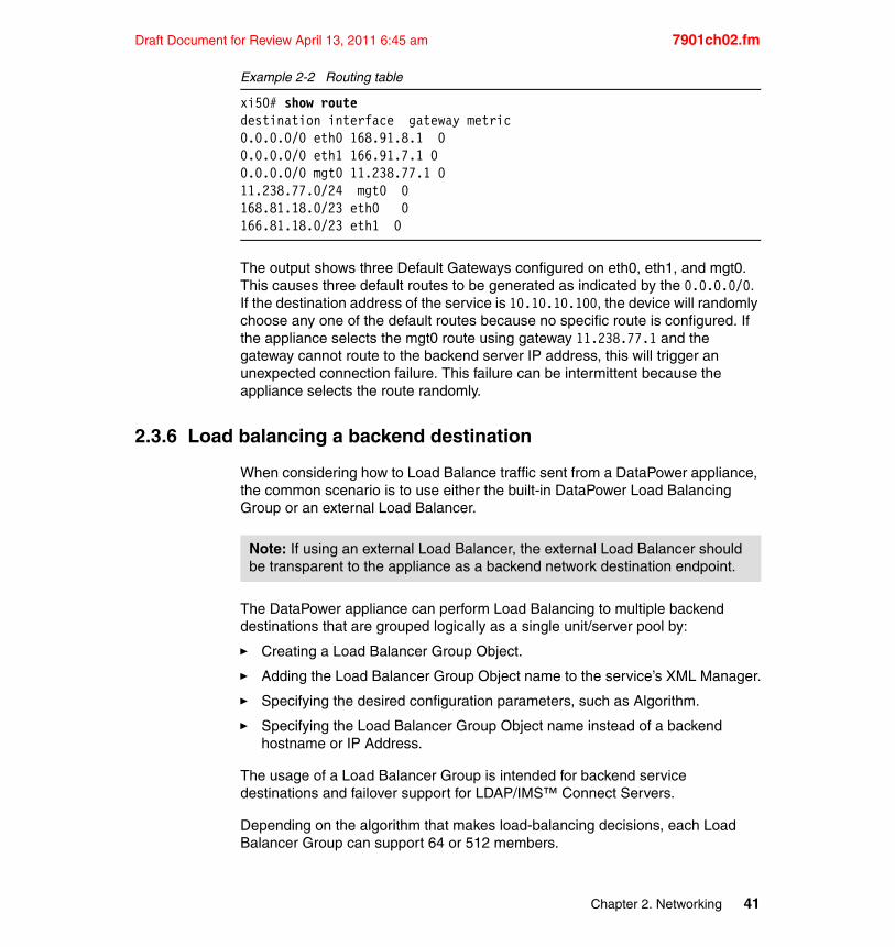
Draft Document for Review April 13, 2011 6:45 am 7901ch02.fm
Example 2-2 Routing table
xi50# show routedestination interface gateway metric 0.0.0.0/0 eth0 168.91.8.1 0 0.0.0.0/0 eth1 166.91.7.1 0 0.0.0.0/0 mgt0 11.238.77.1 0 11.238.77.0/24 mgt0 0 168.81.18.0/23 eth0 0 166.81.18.0/23 eth1 0
The output shows three Default Gateways configured on eth0, eth1, and mgt0. This causes three default routes to be generated as indicated by the 0.0.0.0/0. If the destination address of the service is 10.10.10.100, the device will randomly choose any one of the default routes because no specific route is configured. If the appliance selects the mgt0 route using gateway 11.238.77.1 and the gateway cannot route to the backend server IP address, this will trigger an unexpected connection failure. This failure can be intermittent because the appliance selects the route randomly.
2.3.6 Load balancing a backend destination
When considering how to Load Balance traffic sent from a DataPower appliance, the common scenario is to use either the built-in DataPower Load Balancing Group or an external Load Balancer.
The DataPower appliance can perform Load Balancing to multiple backend destinations that are grouped logically as a single unit/server pool by:
� Creating a Load Balancer Group Object.
� Adding the Load Balancer Group Object name to the service’s XML Manager.
� Specifying the desired configuration parameters, such as Algorithm.
� Specifying the Load Balancer Group Object name instead of a backend hostname or IP Address.
The usage of a Load Balancer Group is intended for backend service destinations and failover support for LDAP/IMS™ Connect Servers.
Depending on the algorithm that makes load-balancing decisions, each Load Balancer Group can support 64 or 512 members.
Note: If using an external Load Balancer, the external Load Balancer should be transparent to the appliance as a backend network destination endpoint.
Chapter 2. Networking 41
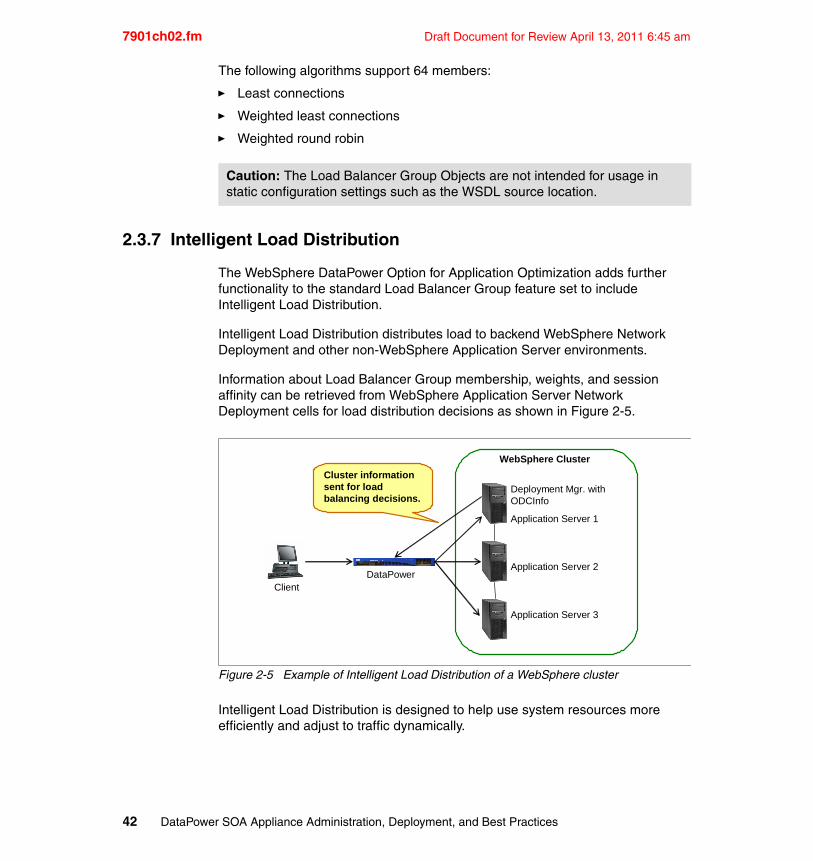
7901ch02.fm Draft Document for Review April 13, 2011 6:45 am
The following algorithms support 64 members:
� Least connections
� Weighted least connections
� Weighted round robin
2.3.7 Intelligent Load Distribution
The WebSphere DataPower Option for Application Optimization adds further functionality to the standard Load Balancer Group feature set to include Intelligent Load Distribution.
Intelligent Load Distribution distributes load to backend WebSphere Network Deployment and other non-WebSphere Application Server environments.
Information about Load Balancer Group membership, weights, and session affinity can be retrieved from WebSphere Application Server Network Deployment cells for load distribution decisions as shown in Figure 2-5.
Figure 2-5 Example of Intelligent Load Distribution of a WebSphere cluster
Intelligent Load Distribution is designed to help use system resources more efficiently and adjust to traffic dynamically.
Caution: The Load Balancer Group Objects are not intended for usage in static configuration settings such as the WSDL source location.
Deployment Mgr. withODCInfo
Application Server 1
Application Server 2
Application Server 3
ClientDataPower
WebSphere Cluster
Cluster information sent for load balancing decisions.
42 DataPower SOA Appliance Administration, Deployment, and Best Practices
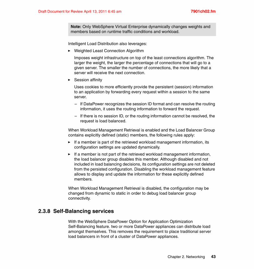
Draft Document for Review April 13, 2011 6:45 am 7901ch02.fm
Intelligent Load Distribution also leverages:
� Weighted Least Connection Algorithm
Imposes weight infrastructure on top of the least connections algorithm. The larger the weight, the larger the percentage of connections that will go to a given server. The smaller the number of connections, the more likely that a server will receive the next connection.
� Session affinity
Uses cookies to more efficiently provide the persistent (session) information to an application by forwarding every request within a session to the same server.
– If DataPower recognizes the session ID format and can resolve the routing information, it uses the routing information to forward the request.
– If there is no session ID, or the routing information cannot be resolved, the request is load balanced.
When Workload Management Retrieval is enabled and the Load Balancer Group contains explicitly defined (static) members, the following rules apply:
� If a member is part of the retrieved workload management information, its configuration settings are updated dynamically.
� If a member is not part of the retrieved workload management information, the load balancer group disables this member. Although disabled and not included in load balancing decisions, its configuration settings are not deleted from the persisted configuration. Disabling the workload management feature allows to display and update the information for these explicitly defined members.
When Workload Management Retrieval is disabled, the configuration may be changed from dynamic to static in order to debug load balancer group connectivity.
2.3.8 Self-Balancing services
With the WebSphere DataPower Option for Application Optimization Self-Balancing feature. two or more DataPower appliances can distribute load amongst themselves. This removes the requirement to place traditional server load balancers in front of a cluster of DataPower appliances.
Note: Only WebSphere Virtual Enterprise dynamically changes weights and members based on runtime traffic conditions and workload.
Chapter 2. Networking 43
7901ch02.fm Draft Document for Review April 13, 2011 6:45 am
When Self-Balancing is enabled, one appliance is designated as the distributor of traffic across the front of the cluster.
Figure 2-6 on page 44 shows the request flow of two self-balanced requests.
Figure 2-6 Example of Self-Balancing
Self-Balancing is fault-tolerant by providing high availability and is built on top of Standby Control. The virtual IP address of the Standby Control configuration is the external address used for Self-Balancing.
If the appliance acting as the distributor fails, another cluster member will assume the role of the distributor and take ownership of the virtual IP address.
All of the DataPower appliances in the group are aware of all shared services.
Important Self-Balancing usage considerations:
� Requires coordination with network team
� Must have rapid spanning tree enabled
� Convergence should be less than six seconds in the event of a MAC address change
� Must not use the same Standby Control group as any other hot standby router protocol (HSRP) group deployed on the same network
2.3.9 Load Balancer health checking
This section describes usage considerations of health checking to the Front-Side and from the Back-Side of the appliance.
Here are some types of health checks that might be used to detect whether a service is available:
Response 1
Request 1
Request 2
Response 2
Standby
Active
Virtual IP – 10.19.0.1
10.19.0.15
10.19.0.5
44 DataPower SOA Appliance Administration, Deployment, and Best Practices
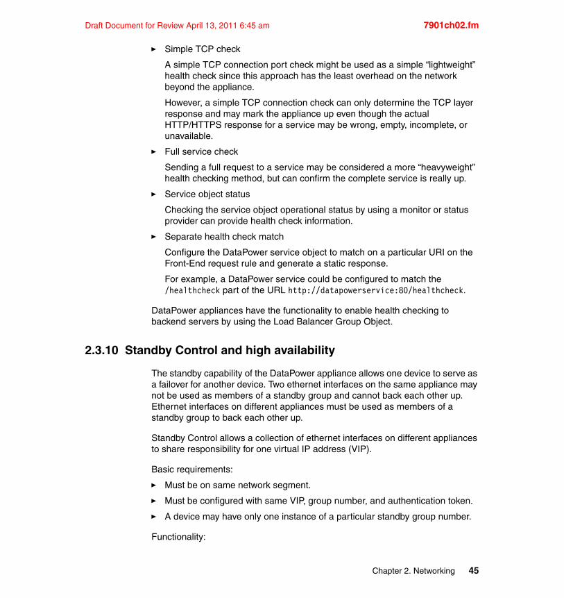
Draft Document for Review April 13, 2011 6:45 am 7901ch02.fm
� Simple TCP check
A simple TCP connection port check might be used as a simple “lightweight” health check since this approach has the least overhead on the network beyond the appliance.
However, a simple TCP connection check can only determine the TCP layer response and may mark the appliance up even though the actual HTTP/HTTPS response for a service may be wrong, empty, incomplete, or unavailable.
� Full service check
Sending a full request to a service may be considered a more “heavyweight” health checking method, but can confirm the complete service is really up.
� Service object status
Checking the service object operational status by using a monitor or status provider can provide health check information.
� Separate health check match
Configure the DataPower service object to match on a particular URI on the Front-End request rule and generate a static response.
For example, a DataPower service could be configured to match the /healthcheck part of the URL http://datapowerservice:80/healthcheck.
DataPower appliances have the functionality to enable health checking to backend servers by using the Load Balancer Group Object.
2.3.10 Standby Control and high availability
The standby capability of the DataPower appliance allows one device to serve as a failover for another device. Two ethernet interfaces on the same appliance may not be used as members of a standby group and cannot back each other up. Ethernet interfaces on different appliances must be used as members of a standby group to back each other up.
Standby Control allows a collection of ethernet interfaces on different appliances to share responsibility for one virtual IP address (VIP).
Basic requirements:
� Must be on same network segment.
� Must be configured with same VIP, group number, and authentication token.
� A device may have only one instance of a particular standby group number.
Functionality:
Chapter 2. Networking 45
7901ch02.fm Draft Document for Review April 13, 2011 6:45 am
� Operates in active/standby (active/passive) mode.
� Interfaces with the highest priority will be the active member.
� Allows for interface failover to another device.
2.4 Best practices
After taking in the full consideration of the usage previously discussed, here is a collection of best practices drawn from experience in the field.
2.4.1 Avoid using 0.0.0.0 as a listener
Binding a specific IP address and port to a specific service is recommended instead of using 0.0.0.0.
Using 0.0.0.0 as a listening address is typically not a good practice since this will allow all interfaces to receive traffic for the assigned port. This may be an unnecessary exposure when services are set to listen on this address.
2.4.2 Separating management traffic
The DataPower appliance can be managed over the network through various methods such as the WebGUI, SSH, Telnet, XML Management Interface, and SNMP.
Management traffic should typically be separated from service traffic.
Careful construction of the routing configuration with non-overlapping routes can help isolate the front side, back side, and management traffic. This can help prevent an attacker from directly connecting to the management interface even from the back side. Traffic separation can be achieved by binding the management interfaces to a specific management IP address or VLAN address.
A common scenario for management traffic separation is to have separate management interface routes for the back-side and front-side.
It is not recommended to bind management interfaces to 0.0.0.0.
If more than one IP address is required for management services, an alternative could be to use a TCP Proxy listening on a second IP address which then points to the original management IP address.
46 DataPower SOA Appliance Administration, Deployment, and Best Practices
Draft Document for Review April 13, 2011 6:45 am 7901ch02.fm
2.4.3 Specify port values less than 10,000
Ports with a value of less than 10,000 should be used when configuring services or protocol handlers. The DataPower appliance uses port values of 10,000 and greater as ephemeral ports. Using ports above 10,000 could cause a port conflict and prevent the service from initializing properly.
2.4.4 Persistent timeout consideration
DataPower’s back persistent timeout should typically be lower than the backend server's timeout to prevent the reuse of a closed connection. The may help to avoid the inherent race condition where the server side may close a connection at the same time further data is being sent from the appliance.
2.4.5 Disable chained persistent connections
Services that communicate within the same appliance should have persistent connections disabled over that connection. Failure to disable persistent connections may cause undesirable results such as connection errors or unexpected memory usage.
The connection errors are associated with the inherent race condition that may occur using an HTTP POST. This may cause the occurrence of a simultaneous POST at one endpoint and a TCP close at the other end.
Additionally, memory overhead may occur for a build-up of many local long-running persistent connections.
This method should be consolidated and not used across too many levels whenever possible, as serialization/de-serialization will occur when passing messages from one service to another.
2.4.6 Configure network settings to be portable
Using host alias, static host, and externalizing end points in XSLT may help make a configuration more portable and maintainable. Using these is recommended instead of designating an explicit IP address in Service configuration. Doing this can allow easier Service migration to another appliance. Otherwise, every configuration reference to the unique IP address on one appliance would need to be modified to correspond with the new appliance’s IP address.
Chapter 2. Networking 47
7901ch02.fm Draft Document for Review April 13, 2011 6:45 am
2.4.7 Multiple default gateways will create multiple default routes
The appliance allows multiple default gateways to be configured and can have one on each of the four interfaces. This was designed to meet the requirements of having a robust appliance. The network administrator should choose the number of default gateways based on network design.
A general recommendation is to set specific static routes and use only one default gateway that can catch all traffic not explicitly being directed by the static routes. This may cause intermittent failure in connecting to other network destinations. The default routes are generated when the default gateway is configured on each interface.
It is recommended to use one default gateway that should be chosen to connect with other destinations/subnets outside of the network and use static routes inside of the network. For example, use the default gateway to connect all internet-based servers and clients, then use a static route to the Intranet servers which may include the back-end application servers.
2.4.8 Standby Control best practices
This section describes the best practices for Standby Control deployment.
Priority and PreemptEnsure that the Priority set on each interface is unique. It is not recommended to have multiple interfaces set to the same Priority value.
Preempt mode should be set to OFF. This is recommended to simplify the configuration and to help with debugging in the event that there are unexpected network delays which could cause the interfaces to start switching between the active and standby states.
Group numberAn integer used to identify a standby group; allowable identifiers are in the range 1 through 255. All interfaces in a given standby group must have the same group number. This value must be distinct from all group numbers being used by IP routers or switches in the same broadcast domain.
The active interface in the group will change its ethernet MAC address to 00:00:0C:07:AC:XX, where XX is the group number. This number must also be unique among all standby groups on a given system.
Configure the standby group number with a value higher than 20. This will help avoid the accidental use of duplicate group numbers within a single network as it
48 DataPower SOA Appliance Administration, Deployment, and Best Practices
Draft Document for Review April 13, 2011 6:45 am 7901ch02.fm
is very common for network routers and switches to be configured with the lower standby group numbers.
Virtual IP addressThe IP address that will be used by the active member of the standby group. External clients that want to be able to contact the active member of the standby group should use this IP address. This address must be on the same IP subnet as the primary address of the interface.
Rapid Spanning TreeEnsure that Spanning Tree PortFast (or Rapid Spanning Tree, depending on the make/model of the switch) is enabled on all switches that are connected to the DataPower appliances. This should also be enabled on any other switches within the network path of the appliances. This will place the switch ports into a forwarding state that will allow traffic to be passed through immediately whenever the VIP moves to the currently active device. Refer to the switch operation manual for configuring this setting.
Make sure that Rapid Spanning Tree is properly deployed and that the convergence time on the switch is less than the “hold” time configured on the appliance. The default “hold” time on the appliance is 10 seconds. This should help allow the proper amount of time to complete a failover and help prevent unnecessary fail-overs caused by misconfiguration.
If the Rapid Spanning Tree is properly deployed and the convergence time requires longer than 10 seconds, the “hello” and “hold” time intervals on the appliance to accommodate the switch can be changed by using the standby CLI command.
For example, issue the command shown in Example 2-3 from the CLI, where 100 is the group number, 5 is the hello time, and 15 is the hold time.
Example 2-3 config command for changing intervals
configint eth0standby 100 timers 5 15
Note: It is not recommended changing the intervals on the appliance because in rare instances that required the timer values to be larger than the default setting. Also, keep in mind that larger timers would mean longer periods to detect when a failover should occur.
Chapter 2. Networking 49
7901ch02.fm Draft Document for Review April 13, 2011 6:45 am
2.4.9 Management interface and default route
Since all network interfaces available in DataPower devices are the same and one of the interfaces is named mgmt only to help distinguish it from others, any interface can be used as a management port and one or more DataPower network interfaces can be used to route network traffic to/from the device.
As a general rule, the management interface should not have the default gateway set, because it is generally recommended to restrict the connections that can be made through that interface.
2.4.10 Enabling “No Delay Ack” to avoid latency with other systems
If slow performance is observed and a delayed ACK response from an application replying back to the DataPower Appliance, then a latency issue may be the cause. For example, this has been observed using applications such as WebSphere MQ or Tivoli® Access Manager running on AIX®.
By default, AIX has a feature called “delayed acknowledgement” enabled in order to improve performance for some network traffic, such as large chunks of data.
While this has been mainly observed on AIX, this could occur on any operating system that employs a delayed acknowledgment setting.
This feature is controlled by the AIX setting tcp_nodelayack which is set to 0 by default:
tcp_nodelayack=0
However, this AIX default setting can slow down performance communicating between DataPower and some applications such as WebSphere MQ or Tivoli Access Manager.
Changing the default tcp_nodelayack option to enabled (set tcp_nodelayack=1) prompts TCP to send an immediate acknowledgement, rather than the default 200 ms delay.
Sending an immediate acknowledgement might cause a few more ACKs on the network, but in some cases with WebSphere MQ, Tivoli Access Manager, or generally when sending small messages back and forth, it may greatly improve performance.
Use the following suggestions to diagnose the problem:
� Turn the tcp_nodelayack option on and test the performance.
50 DataPower SOA Appliance Administration, Deployment, and Best Practices
Draft Document for Review April 13, 2011 6:45 am 7901ch02.fm
� Review packet traces from DataPower to see if there is a delay between the packet sent to AIX and the ACK response coming back from AIX.
For example, in Wireshark/Ethereal, look for the “Time delta from previous packet” entry for the ACK packet to determine the amount of time elapsed waiting for the ACK.
To resolve this problem, disable the default ACK delay on AIX by changing the setting to:
tcp_nodelayack=1
For example, to see what the current setting is:
/usr/sbin/no -o tcp_nodelayack
To test the option:
/usr/sbin/no -o tcp_nodelayack=1
To make the change persistent across reboots:
/usr/sbin/no -p -o tcp_nodelayack=1
Therefore, do not change the default tcp_nodelayack value unless slow communication with a DataPower Appliance is occurring.
Consult with the AIX system administrator for further considerations about the impact this may have on the system and for further details of how to do this.
2.4.11 Streaming large messages and flow control
Streaming allows a message to start flowing to the backend before the whole message is read from the sending client.
When streaming large messages through a DataPower Multi-Protocol Gateway, it is recommended to utilize the flow control feature to help prevent memory from building up in the case of a slow backend server.
In order to effectively use flow control, it is recommended to verify that a processing policy does not prevent streaming, which is discussed further in the
Note: Although delayed acknowledgement may adversely affect some applications on AIX such as WebSphere MQ or Tivoli Access Manager communications with DataPower, it can improve performance for other network connections.
Chapter 2. Networking 51
7901ch02.fm Draft Document for Review April 13, 2011 6:45 am
Optimizing Through Streaming product documentation available in the DataPower Information Center:
http://www-01.ibm.com/software/integration/datapower/library/documentation/
Also, verify that the XML Manager XML Parser XML Bytes Scanned value used by the service is large enough to handle the desired large file size.
2.5 Examples
This section provides examples of various configuration and troubleshooting techniques.
2.5.1 Externalizing endpoints in a Meta Data document
XSLT often uses environment specific information. Externalizing endpoints in a Meta Data document can help remove the environment specific information from within the XSLT to allow better reusability. Each environment could then contain its own Meta Data document.
Example 2-4 is a Routing example that shows how to externalize endpoints in a Meta Data document.
Example 2-4 Routing example for externalizing endpoints
<routingDestinations><destinations subjectCN="CN=companylocation1">
<host>10.10.10.2</host><port>5000</port><sslid/>
</destinations><destinations subjectCN="CN=companylocation2">
<host>10.10.10.3</host><port>5001</port><sslid/>
</destinations></routingDestinations>
XSL will reference the above Meta Data document as shown in Example 2-5.
52 DataPower SOA Appliance Administration, Deployment, and Best Practices
Draft Document for Review April 13, 2011 6:45 am 7901ch02.fm
Example 2-5 XSL reference to externalized endpoints
<xsl:variablename="endPoints" select="document('local:///identityDocument.xml')//identityDocument/service[@name='bookService']/endPoints"/>
<!--Set routing for Purchases -->
<dp:xset-target host="$endPoints/BookServiceHost1/ip/text()" port="$endPoints/BookServiceHost1/port/text()" ssl="false()"/>
2.5.2 Disabling chained persistent connections for various different points of a service
Persistent connections can be used at various points of a service object, including:
� Front-Side
� Back-Side
� Processing Policy
Disabling persistent connections for Front-SideIf the service is using a Front-Side Handler, persistent connections can be enabled or disabled explicitly in this Front-Side Handler. This is particularly useful if the Front-Side Handler is listening on a local host or 127.0.0.1 IP Address.
Disabling persistent connections for Back-SideIf the service points to a local chained service as a backend, then use the Advanced tab to disable persistent connections going to this local chained service.
Disabling persistent connections in Processing PolicyIf traffic is sent out during a processing policy (url-open), then the User-Agent will dictate the type of connection used. Use the User-Agent to “Restrict to HTTP 1.0" to prevent persistent connections for the processing policy traffic with a match.
Another possibility would be to add the “Connection: close” header to the url-open to prevent persistent connection reuse. See the following website for more information:
http://www.w3.org/Protocols/rfc2616/rfc2616-sec14.html#sec14.10
Chapter 2. Networking 53
7901ch02.fm Draft Document for Review April 13, 2011 6:45 am
2.5.3 Port speed mismatch
If the ethernet interface port speed is configured as auto, the interface setting must be matched by auto on the switch to ensure reliability.
FailureNetwork collisions could be caused by incompatible interface settings on the DataPower device® and the switch.
2.5.4 Sample DNS workaround using static host
Each DNS query response from the DNS server typically contains an IP address along with a time-to-live (TTL) with an IP address/hostname mapping. DataPower will try Host Alias to honor and respect the TTL that is specified in the DNS Server response.
In order to shorten the time that the DNS cache exists from the DataPower side, the DNS servers should be configured with the desired time-to-live. It is recommended that these settings are consistent across all of the DNS servers that are configured for usage with DataPower.
2.5.5 Sample CLI commands to capture DNS server responses
To obtain DNS server information, determine the route that will be used to query the configured DNS server by examining the routing table and the IP address of the DNS server.
When the interface that handles the DNS traffic has been determined, the following commands will get DNS information and a packet capture of the DNS traffic:
� co� show dns � show dns-cache� show ip hosts� clear dns-cache� show dns-cache� show ip hosts� int eth<interface number>� packet-capture temporary:///DNStrace.pcap -1 5000� exit
Workaround: If this is affecting Production Traffic, enter a static host for the IP/hostname mapping in the DNS configuration section of DataPower. This will serve as a temporary workaround so that there is not an outage.
54 DataPower SOA Appliance Administration, Deployment, and Best Practices
Draft Document for Review April 13, 2011 6:45 am 7901ch02.fm
� show clock � ping <hostname of failing DNS entry>� <Wait for the console to return before continuing>� show dns-cache� show ip hosts� show clock � ping <IP Address of failing DNS entry>� <Wait for the console to return before continuing>� show dns-cache� show ip hosts� show clock � int eth<interface number>� no packet-capture temporary:///DNStrace.pcap� exit
2.5.6 Sample test to see if Rapid Spanning Tree has been deployed properly for DataPower Standby Control
If Rapid Spanning Tree is not deployed correctly on the network, then the Standby Control Appliances may not be able to communicate properly.
If the convergence time is more than 6 seconds, the network has not successfully deployed rapid spanning tree and the network administrator should be contacted.
Use the following procedure to determine if rapid spanning tree is deployed.
1. Record the current Standby Control configuration settings, disable Standby Control on both Appliances, and then save the updated configuration.
– Using the WebGUI:
i. Navigate to Network Interface Ethernet Interface eth<number>.
ii. Click the Standby Control tab to view and record the settings.
iii. Click the X next to the Standby Control configuration entry to remove the Standby Control configuration.
iv. Click Apply Save Config.
– Using the CLI:
Example 2-6 Using the CLI
#show standby#co#int eth<number>#no standby
Chapter 2. Networking 55
7901ch02.fm Draft Document for Review April 13, 2011 6:45 am
#exit#write memory#y
2. Reboot both Appliances.
3. Once the Appliances have completed the reboot, check that both have their original MAC addresses.
– Using the WebGUI:
Navigate to Status IP-Network Ethernet Interfaces to view the MAC addresses.
– Using the CLI:
#show int mode
Be sure to record the original MAC addresses for later use.
The next several steps describe how to measure the spanning tree convergence time.
4. Start a continuous ping to one of the DataPower interfaces from another remote host on the network and verify that they are successful.
– Using UNIX®:
ping <DataPower IP>
– Using the Windows® command prompt:
ping -t <DataPower IP>
5. Change the MAC address on the Appliance interface to any MAC address currently not in use on the network. This should cause the continuous pings from the remote host to start failing.
– Using the WebGUI:
i. Navigate to Network Interface Ethernet Interface eth<number>.
ii. Update the MAC address Field and click Apply.
– Using the CLI:
#co#int eth<number>
Note: This should not be the HSRP Virtual MAC Address: 00:00:0c:07:ac:<groupnumber>.
56 DataPower SOA Appliance Administration, Deployment, and Best Practices
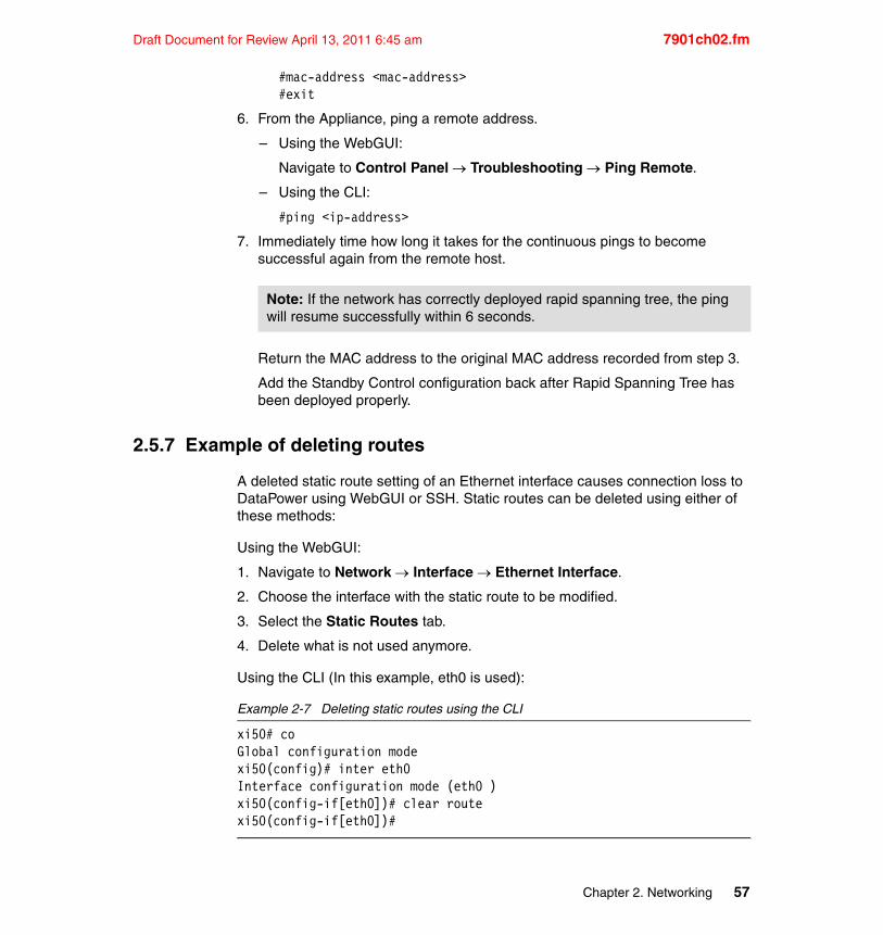
Draft Document for Review April 13, 2011 6:45 am 7901ch02.fm
#mac-address <mac-address>#exit
6. From the Appliance, ping a remote address.
– Using the WebGUI:
Navigate to Control Panel Troubleshooting Ping Remote.
– Using the CLI:
#ping <ip-address>
7. Immediately time how long it takes for the continuous pings to become successful again from the remote host.
Return the MAC address to the original MAC address recorded from step 3.
Add the Standby Control configuration back after Rapid Spanning Tree has been deployed properly.
2.5.7 Example of deleting routes
A deleted static route setting of an Ethernet interface causes connection loss to DataPower using WebGUI or SSH. Static routes can be deleted using either of these methods:
Using the WebGUI:
1. Navigate to Network Interface Ethernet Interface.
2. Choose the interface with the static route to be modified.
3. Select the Static Routes tab.
4. Delete what is not used anymore.
Using the CLI (In this example, eth0 is used):
Example 2-7 Deleting static routes using the CLI
xi50# coGlobal configuration modexi50(config)# inter eth0Interface configuration mode (eth0 )xi50(config-if[eth0])# clear routexi50(config-if[eth0])#
Note: If the network has correctly deployed rapid spanning tree, the ping will resume successfully within 6 seconds.
Chapter 2. Networking 57
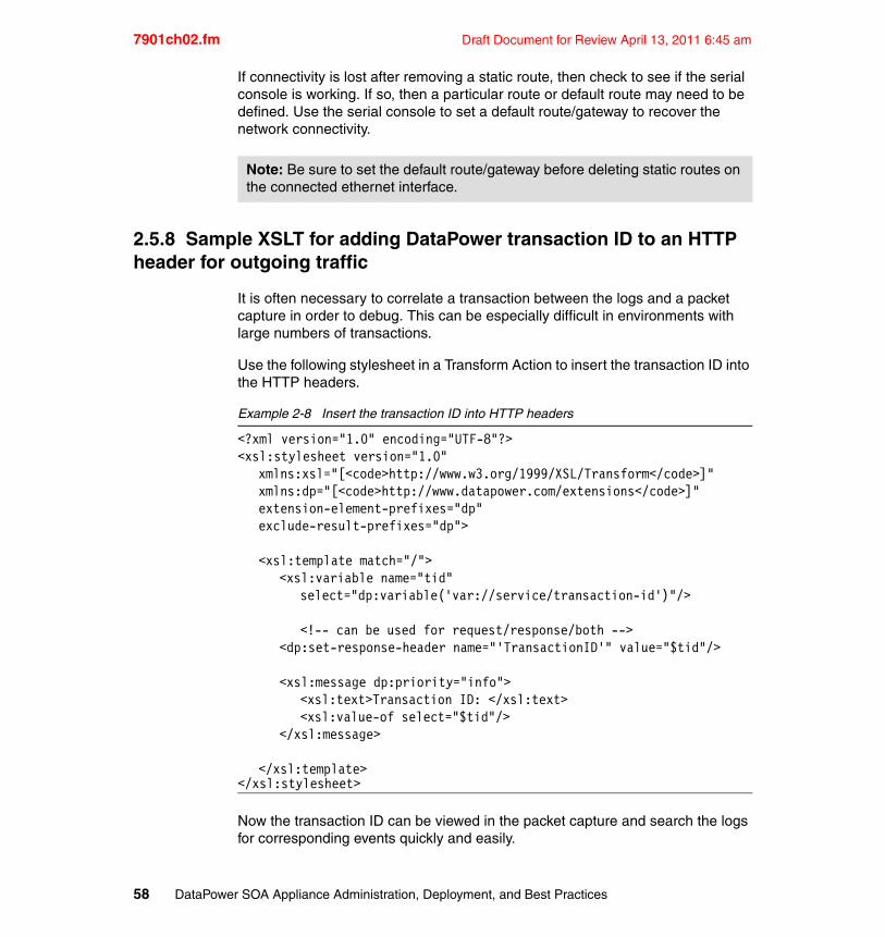
7901ch02.fm Draft Document for Review April 13, 2011 6:45 am
If connectivity is lost after removing a static route, then check to see if the serial console is working. If so, then a particular route or default route may need to be defined. Use the serial console to set a default route/gateway to recover the network connectivity.
2.5.8 Sample XSLT for adding DataPower transaction ID to an HTTP header for outgoing traffic
It is often necessary to correlate a transaction between the logs and a packet capture in order to debug. This can be especially difficult in environments with large numbers of transactions.
Use the following stylesheet in a Transform Action to insert the transaction ID into the HTTP headers.
Example 2-8 Insert the transaction ID into HTTP headers
<?xml version="1.0" encoding="UTF-8"?><xsl:stylesheet version="1.0"
xmlns:xsl="[<code>http://www.w3.org/1999/XSL/Transform</code>]" xmlns:dp="[<code>http://www.datapower.com/extensions</code>]" extension-element-prefixes="dp" exclude-result-prefixes="dp">
<xsl:template match="/"><xsl:variable name="tid"
select="dp:variable('var://service/transaction-id')"/>
<!-- can be used for request/response/both --><dp:set-response-header name="'TransactionID'" value="$tid"/>
<xsl:message dp:priority="info"><xsl:text>Transaction ID: </xsl:text><xsl:value-of select="$tid"/>
</xsl:message>
</xsl:template></xsl:stylesheet>
Now the transaction ID can be viewed in the packet capture and search the logs for corresponding events quickly and easily.
Note: Be sure to set the default route/gateway before deleting static routes on the connected ethernet interface.
58 DataPower SOA Appliance Administration, Deployment, and Best Practices
Draft Document for Review April 13, 2011 6:45 am 7901ch03.fm
Chapter 3. Domains
From a cost perspective, one of the benefits of using DataPower appliances is the ability to use the same physical device to support many different projects and implementations. To support this level of versatility, DataPower appliances provide management functions for the separation of a single physical appliance into one or more logical instances called domains.
This chapter discusses the various benefits, uses, configuration, and best practices that are associated with DataPower domains.
3
© Copyright IBM Corp. 2011. All rights reserved. 59
7901ch03.fm Draft Document for Review April 13, 2011 6:45 am
3.1 Application domains
An application domain is similar to a private workspace. It isolates object configurations and files in one domain from those in other domains. Application domains provide an easy way to logically partition a single DataPower appliance for use by multiple developers, applications, or lines of business.
IT professionals will find that application domains are similar to virtualization solutions and logical partitions (LPARs), which allow a single physical machine to be divided into several virtual systems for distinct usage. There are indeed some similarities; however, unlike a true virtualized system, all DataPower domains share the same system level resources. Memory, CPU, and network interfaces are shared throughout the entire appliance. This shared resource model means that administrators must be careful in how they reuse a single appliance.
As an example, it would be unwise to have a single appliance that had one domain that processes high volume web service traffic and another domain that processes medium volume, very large (perhaps 1 GB) files. The memory consumption of the large files might impede not only available memory (especially if cryptographic functionality is required) but also network capacity.
3.1.1 The default domain
A special administrative domain, named default, contains the device’s global configuration. Network setup, user administration, and other device configuration tasks can be performed only from within the default domain. In addition, application domains can be created and deleted only by administrators who are logged in to the default domain.
3.1.2 Domain use and benefits
Application domains provide a convenient and flexible way of dividing a single appliance into multiple workspaces. Domains are atomic in nature and are managed as a unit. An application domain can be exported easily from one appliance and imported into another one.
How a DataPower appliance is divided depends largely on its role within the enterprise. For example, a development appliance might contain the following domains:
Development within the default domain: Do not do application-related development within the default domain.
60 DataPower SOA Appliance Administration, Deployment, and Best Practices
Draft Document for Review April 13, 2011 6:45 am 7901ch03.fm
� Individual developer domains
� In this case, each developer has a domain so that activities do not disrupt the activities of other developers. This provides each developer with a sandbox for learning, testing, and troubleshooting.Shared project domains
In this case, the domain can represent a single project (or application). Developers might build components in their own development domains and copy these components into this domain for integration with pieces created by other developers. This domain ultimately is promoted to test and production appliances.
Test and production appliances generally contain domains for specific applications or lines of business and rarely, if ever, contain developer domains.
The DataPower appliance domain model provides a number of benefits:
� Logical segregation
– Workspace segregation
Developers are segregated from each other. Role Based Management (RBM) access policies can easily restrict developers from accessing each other’s domains.
– Message segregation
Messages from one domain are not visible within other domains (except the default domain).
– Application segregation
A single domain can contain a set of services or configuration objects that are used by a single enterprise application. This type of segregation facilitates easy promotion between appliances and easy overall management and policy enforcement at the domain level.
– Line of business (LOB) segregation
A single domain can contain all services for a specific LOBs.
� Easy backup and restore (import/export)
With just a few actions, an entire domain can be exported or imported, making migration relatively easy. Import and export can also be automated using the CLI (scripting) or the XML Management Interface (XMI). Deployment policies further enhance this process by allowing specific elements within a configuration to be modified during an import operation. For example, the test environment can use a host name of wsgatewaytst as a back-end service, but in production it must be changed to wsgateway.
� Access control
Chapter 3. Domains 61
7901ch03.fm Draft Document for Review April 13, 2011 6:45 am
Using role-based management, domains are easily protected and secured by unauthorized access.
� Version control
Domains can be exported as a compressed file or as an XML file and saved within any popular source code management solution.
� Easy rollback
Using either backup and restore functionality or the built-in configuration checkpoints facility, domains can be easily rolled back to a configuration from a previous point in time.
3.1.3 Segregating projects and LOBs
Application domains provide a useful way of supporting many projects from different business and technology teams within the same physical appliance. The segregation of configuration provides some assurance to business stakeholders that their implementations will not be impacted when another business’ configuration is deployed to the production environment.
However, it is important to remember that the same physical system resources are shared across the device. Project teams and LOBs must be made aware of this fact and must be willing to accept the risk that over utilization of processing or memory resources by one domain might impact their application.
If this risk is deemed unacceptable by the stakeholders, it might be necessary to purchase additional devices and physically separate usage. Alternatively, a DataPower team can use a process of capacity planning with negotiation of service level agreements and DataPower service level monitors (SLM) to greatly reduce the risk that a single application domain will consume an inordinate amount of system resources. See the Service Level Monitoring topic in the DataPower Information Center for more details about SLM functionality (the URL can be found in 3.6, “Further reading”).
3.1.4 Number of domains on an appliance
Although there is no set limit on the number of application domains that can be configured on a single appliance, there are several environmental considerations worth assessing to safeguard against exhaustion of DataPower system resources. For example, having one application domain with 20 complex services will impose a larger strain on system resources than 10 application domains with 10 simple services.
62 DataPower SOA Appliance Administration, Deployment, and Best Practices
Draft Document for Review April 13, 2011 6:45 am 7901ch03.fm
3.1.5 Domain resource consumption
The existence of a domain requires a negligible amount of system memory and is not generally a consideration in overall capacity planning. A new (or empty) domain’s private flash file system also consumes minimal resources with the exception of the domain’s default logs.
When a domain is created, it includes a single log target that is configured to send log messages to a flash-based file in the logtemp: directory. The file has an upper size limit of 500 KB; however, the log target is configured for three rotations. Thus, when the default log file becomes full, it is archived up to three times, which results in 2 MB of space in the flash file system. Depending on the amount of flash memory resident in the appliance, this space consumption might be worthy of consideration.
3.2 Domain structure
All domains contain the same basic structure and capabilities:
� A domain-specific file system is used to organize and persist various details about the domain, such as configuration, XSL templates, cryptographic certificates, and so forth. We discuss the file system in 3.2.1, “Local flash-based file system” on page 64.
� A domain-specific configuration file includes configuration details that pertain to all objects that are created within the domain. We discuss configuration files in 3.2.2, “Domain configuration files” on page 66.
� A domain-specific logging system is isolated from logged output that is generated in other domains. We discuss domain logging further in 3.2.3, “Domain logging” on page 66.
� All domains have access to shared system resources, such as CPU, memory, and network interfaces.
Consideration: There is no limit to the number of domains that can be created on a single DataPower appliance. However, because all domains share system resources, it is prudent to evaluate whether introducing a new domain on an existing appliance will negatively impact other domains.
Space considerations: Although a domain consumes minimal system resources, its default logs require at least 2 MB on the flash file system.
Chapter 3. Domains 63
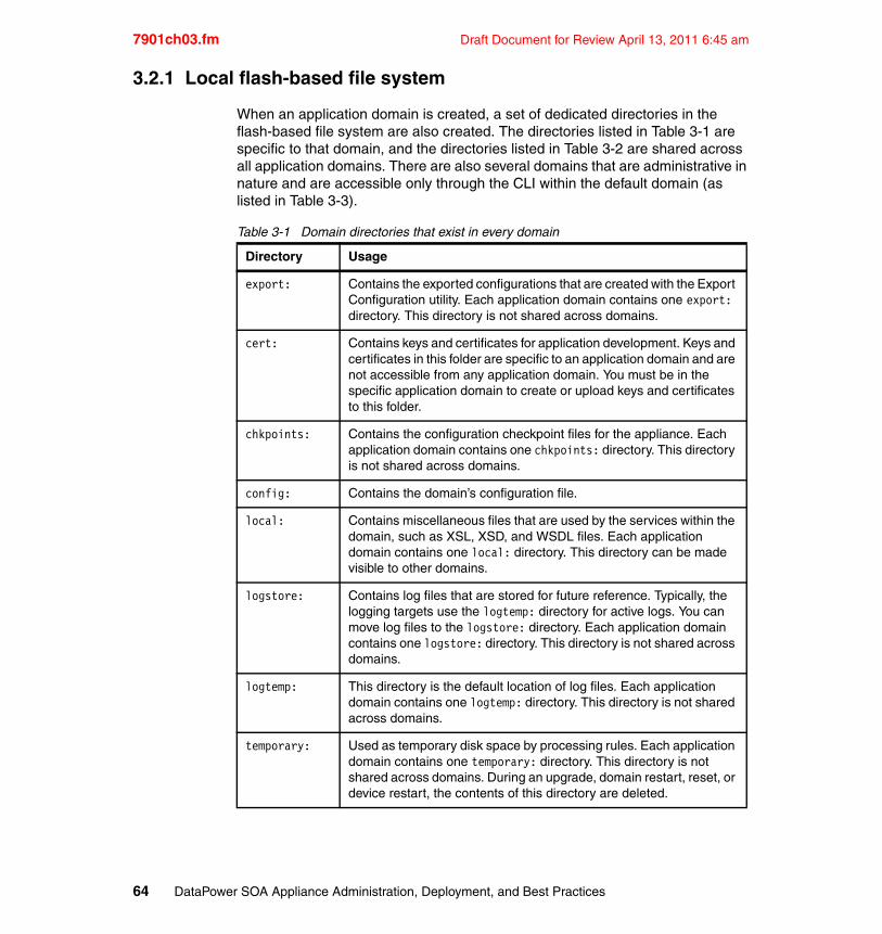
7901ch03.fm Draft Document for Review April 13, 2011 6:45 am
3.2.1 Local flash-based file system
When an application domain is created, a set of dedicated directories in the flash-based file system are also created. The directories listed in Table 3-1 are specific to that domain, and the directories listed in Table 3-2 are shared across all application domains. There are also several domains that are administrative in nature and are accessible only through the CLI within the default domain (as listed in Table 3-3).
Table 3-1 Domain directories that exist in every domain
Directory Usage
export: Contains the exported configurations that are created with the Export Configuration utility. Each application domain contains one export: directory. This directory is not shared across domains.
cert: Contains keys and certificates for application development. Keys and certificates in this folder are specific to an application domain and are not accessible from any application domain. You must be in the specific application domain to create or upload keys and certificates to this folder.
chkpoints: Contains the configuration checkpoint files for the appliance. Each application domain contains one chkpoints: directory. This directory is not shared across domains.
config: Contains the domain’s configuration file.
local: Contains miscellaneous files that are used by the services within the domain, such as XSL, XSD, and WSDL files. Each application domain contains one local: directory. This directory can be made visible to other domains.
logstore: Contains log files that are stored for future reference. Typically, the logging targets use the logtemp: directory for active logs. You can move log files to the logstore: directory. Each application domain contains one logstore: directory. This directory is not shared across domains.
logtemp: This directory is the default location of log files. Each application domain contains one logtemp: directory. This directory is not shared across domains.
temporary: Used as temporary disk space by processing rules. Each application domain contains one temporary: directory. This directory is not shared across domains. During an upgrade, domain restart, reset, or device restart, the contents of this directory are deleted.
64 DataPower SOA Appliance Administration, Deployment, and Best Practices
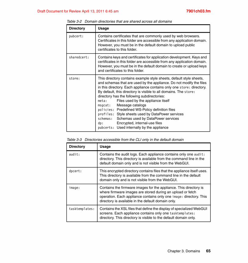
Draft Document for Review April 13, 2011 6:45 am 7901ch03.fm
Table 3-2 Domain directories that are shared across all domains
Table 3-3 Directories accessible from the CLI only in the default domain
Directory Usage
pubcert: Contains certificates that are commonly used by web browsers. Certificates in this folder are accessible from any application domain. However, you must be in the default domain to upload public certificates to this folder.
sharedcert: Contains keys and certificates for application development. Keys and certificates in this folder are accessible from any application domain. However, you must be in the default domain to create or upload keys and certificates to this folder.
store: This directory contains example style sheets, default style sheets, and schemas that are used by the appliance. Do not modify the files in this directory. Each appliance contains only one store: directory. By default, this directory is visible to all domains. The store: directory has the following subdirectories:meta: Files used by the appliance itselfmsgcat: Message catalogspolicies: Predefined WS-Policy definition filesprofiles: Style sheets used by DataPower servicesschemas: Schemas used by DataPower servicesdp: Encrypted, internal-use filespubcerts: Used internally by the appliance
Directory Usage
audit: Contains the audit logs. Each appliance contains only one audit: directory. This directory is available from the command line in the default domain only and is not visible from the WebGUI.
dpcert: This encrypted directory contains files that the appliance itself uses. This directory is available from the command line in the default domain only and is not visible from the WebGUI.
image: Contains the firmware images for the appliance. This directory is where firmware images are stored during an upload or fetch operation. Each appliance contains only one image: directory. This directory is available in the default domain only.
tasktemplates: Contains the XSL files that define the display of specialized WebGUI screens. Each appliance contains only one tasktemplates: directory. This directory is visible to the default domain only.
Chapter 3. Domains 65
7901ch03.fm Draft Document for Review April 13, 2011 6:45 am
3.2.2 Domain configuration files
Every application domain includes at least one configuration file, which is kept in the config: directory. The domain configuration file contains a script of CLI commands that are executed to initialize all of the service and configuration objects within the domain.
At device startup, the default domain’s configuration file is executed first, initializing the network, administrative interfaces, and other device-wide settings. It also includes a number of commands that create all of the user-defined application domains. As each domain is initialized, its configuration script is executed, building all of the services and configuration objects for that domain.
The configuration script for the default domain is named autoconfig.cfg. The configuration script in each application domain is named the same as the domain with a .cfg extension. For example, the configuration file for a domain named wsgateway would be wsgateway.cfg and would be found in that domain’s config: directory.
3.2.3 Domain logging
Every application domain includes its own isolated logging subsystem, which operates only on log messages that are generated by service objects defined within the same domain. Log messages do not cross domain boundaries, with the exception of the default domain, which is capable of receiving messages from all domains. When a new application domain is created, a log target named default-log is created.
As you might expect, each domain can control the level (or severity) of log messages that are generated within the domain. Log levels range from emergency to debug, with the latter generating the most log messages. Setting the log level in one domain has no effect on logging in other domains. You can determine the log level for a specific domain by clicking the Troubleshooting Panel icon from within the main Control Panel.
We describe logging capabilities in more detail in Chapter 6, “Logging” on page 153.
3.2.4 Domain monitoring
Domains can provide monitoring systems with metrics that pertain to service activity. When a domain is created, this functionality is initially disabled, but you can enable it using Administration Device Statistic Settings.
66 DataPower SOA Appliance Administration, Deployment, and Best Practices
Draft Document for Review April 13, 2011 6:45 am 7901ch03.fm
We discuss device monitoring in more detail in Chapter 4, “SNMP monitoring” on page 77.
3.2.5 Shared resources
Although application domains provide a convenient mechanism for logically partitioning a DataPower device, they do not provide any segmentation of global system resources. System resources such as processor, memory, network cards, and storage are shared across all domains on a single physical device and cannot be partitioned. Thus, if a configuration running on a single application domain experiences heavy use, it can consume the majority of system resources and leave little resources for other configurations running on the same appliance. Although there is limited support for prioritization of services, using global system resources cannot be restricted to a specific application domain.
In addition to physical system resources considerations, be aware that a DataPower device can run only a single firmware image at a time. For application domains, the impact is that all domains must operate with the same firmware version, which might be a consideration when planning the number of devices per user for development, testing, and production environments.
3.3 Domain persistence
When an administrator creates a new application domain, the following actions occur:
� System memory (RAM) is allocated for the domain.
� The domain’s directory structure is allocated in the file system.
� A configuration file is created in the config: directory.
� The logging and monitoring subsystems are initialized for the domain, along with any preconfigured log targets.
3.3.1 Saving configuration changes
When these actions complete, the domain is active in memory and ready for administrative or development activities. From this point on, any configuration actions that are performed within the domain, such as creating a new Web Service Proxy or defining an MQ Connection Manager, result in the immediate creation of memory-resident objects.
Chapter 3. Domains 67
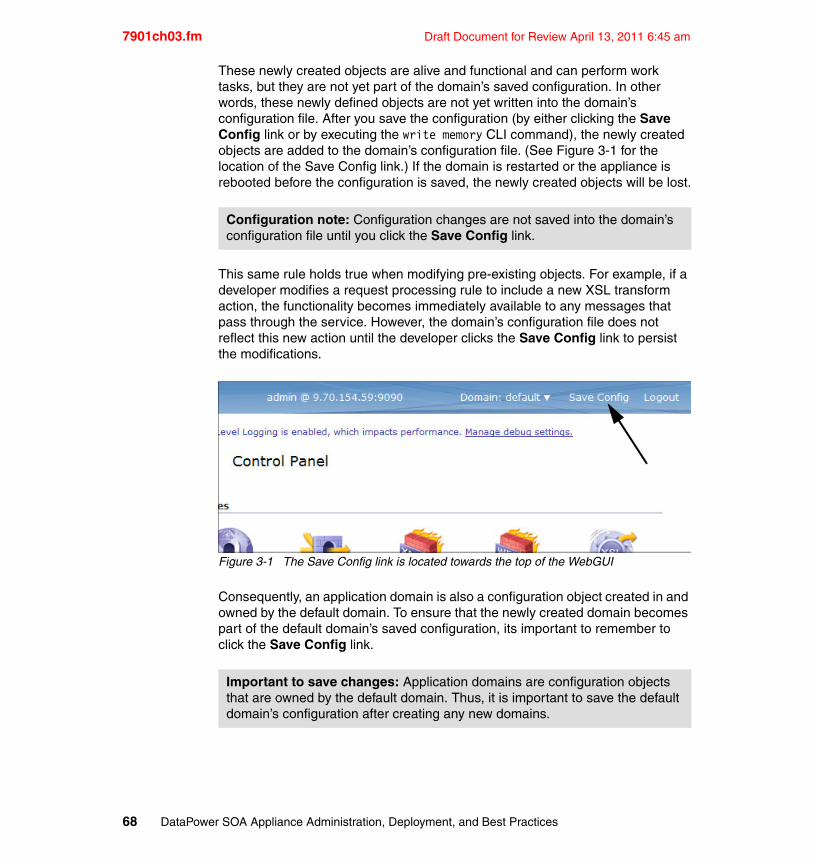
7901ch03.fm Draft Document for Review April 13, 2011 6:45 am
These newly created objects are alive and functional and can perform work tasks, but they are not yet part of the domain’s saved configuration. In other words, these newly defined objects are not yet written into the domain’s configuration file. After you save the configuration (by either clicking the Save Config link or by executing the write memory CLI command), the newly created objects are added to the domain’s configuration file. (See Figure 3-1 for the location of the Save Config link.) If the domain is restarted or the appliance is rebooted before the configuration is saved, the newly created objects will be lost.
This same rule holds true when modifying pre-existing objects. For example, if a developer modifies a request processing rule to include a new XSL transform action, the functionality becomes immediately available to any messages that pass through the service. However, the domain’s configuration file does not reflect this new action until the developer clicks the Save Config link to persist the modifications.
Figure 3-1 The Save Config link is located towards the top of the WebGUI
Consequently, an application domain is also a configuration object created in and owned by the default domain. To ensure that the newly created domain becomes part of the default domain’s saved configuration, its important to remember to click the Save Config link.
Configuration note: Configuration changes are not saved into the domain’s configuration file until you click the Save Config link.
Important to save changes: Application domains are configuration objects that are owned by the default domain. Thus, it is important to save the default domain’s configuration after creating any new domains.
68 DataPower SOA Appliance Administration, Deployment, and Best Practices
Draft Document for Review April 13, 2011 6:45 am 7901ch03.fm
3.3.2 Imported domain configurations
By default, when a domain is created, its configuration is stored locally as described in 3.2.2, “Domain configuration files” on page 66. It is also possible to create a domain that, when started, imports its configuration from a remote location. Both local and imported domains have specific usage scenarios and considerations.
Local domainsDomains that are purposed for development are always defined as local. As developers modify the objects within the domain, they save the active configuration to the local configuration file. If the domain or appliance is restarted, the saved configuration is used to reconstitute the domain.
Imported domainsImported domains fetch their configuration from a remote location. This type of domain is read-only. After a domain is initialized, any changes that occur to the running configuration cannot be saved, which disqualifies imported domains for development use. However, imported domains are ideally suited for test and production environments.
3.4 Usage considerations
Domains provide a powerful and convenient way to segment a single DataPower appliance. Creating and using domains is simple and intuitive; however, this section provides additional guidance when configuring or using domains.
3.4.1 Cross-domain file visibility
An application domain can be provided with read-only access to any other domain’s local: directory. By default, all domains are created with visibility into the default domain. Domain visibility is added (or removed) during domain creation or modification (see Figure 3-2).
Modifying imported domains: An imported domain’s running configuration can be modified, but the modifications cannot be saved. When the appliance is rebooted or the domain is restarted, those changes are lost. Changes can be made only to local domains.
Chapter 3. Domains 69
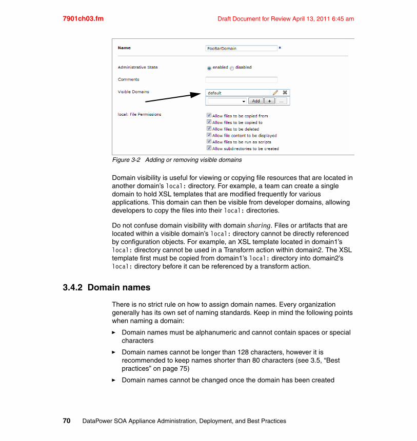
7901ch03.fm Draft Document for Review April 13, 2011 6:45 am
Figure 3-2 Adding or removing visible domains
Domain visibility is useful for viewing or copying file resources that are located in another domain’s local: directory. For example, a team can create a single domain to hold XSL templates that are modified frequently for various applications. This domain can then be visible from developer domains, allowing developers to copy the files into their local: directories.
Do not confuse domain visibility with domain sharing. Files or artifacts that are located within a visible domain’s local: directory cannot be directly referenced by configuration objects. For example, an XSL template located in domain1’s local: directory cannot be used in a Transform action within domain2. The XSL template first must be copied from domain1’s local: directory into domain2’s local: directory before it can be referenced by a transform action.
3.4.2 Domain names
There is no strict rule on how to assign domain names. Every organization generally has its own set of naming standards. Keep in mind the following points when naming a domain:
� Domain names must be alphanumeric and cannot contain spaces or special characters
� Domain names cannot be longer than 128 characters, however it is recommended to keep names shorter than 80 characters (see 3.5, “Best practices” on page 75)
� Domain names cannot be changed once the domain has been created
70 DataPower SOA Appliance Administration, Deployment, and Best Practices
Draft Document for Review April 13, 2011 6:45 am 7901ch03.fm
Although it is not possible to rename a domain, you can migrate an existing domain easily to a domain with the desired name.
Exporting and importingThe contents of a source domain can be exported and then imported into a newly created domain. This method has the advantage of exporting the domain’s local: directory. It might be necessary to re-import private key material into the cert: directory, because keys are generally not included in domain exports.
To export and then import a domain:
1. Export the source domain, and download the exported compressed file, which is used as the import into step 3 but also as a backup of the original domain if it is necessary to undo these actions.
2. Create a new domain with the desired name.
3. Import the compressed file into the new domain.
4. (Optional) Upload any private key material into the domain’s cert: directory.
5. Disable the source domain.
6. Test the new domain.
7. Delete the source domain.
Copying the configuration file using the CLIIf there is little or no dependence on the local: directory, it might be easier to create a new domain and then copy the configuration file from the original domain into the newly created domain.
Copying the configuration file does not automatically include any artifacts that exist in the source domain’s local: directory; therefore, it might be necessary to copy the contents of the source domain’s local: directory to the new domain as well. It might also be necessary to upload any dependent private key material.
Renaming a domain: The methods that we describe provide an alternate means of renaming a domain by copying its contents to a new domain and then removing the original domain. Take care to ensure that all artifacts in the source domain’s local: and cert: directories are reproduced in the new destination domain.
Note: Maintaining required artifacts on an external server avoids the need to copy them from one domain to another. This applies also to private key material which can possibly be kept in the sharedcert: directory.
Chapter 3. Domains 71
7901ch03.fm Draft Document for Review April 13, 2011 6:45 am
Example 3-1 shows the CLI commands to copy a domain to a new domain.
Example 3-1 Copying one domain to another
configure terminaldomain SourceDomain; admin-state disabled; exitdomain DestDomain; exitcopy -f config:/SrcDomain/SrcDomain.cfg config:/DestDomain/DesetDomain.cfgrestart domain DestDomainexit;
The commands in this example accomplish the following tasks:
1. Disable the source domain (SourceDomain).
2. Create a new domain named DestDomain.
3. Copy the configuration file from the SourceDomain to DestDomain. Notice that the new file is renamed to the domain’s name. The -f parameter overwrites the existing file.
4. Restart the new domain. Restarting a domain rebuilds the domain based on the new configuration file.
Note that no files from the local: directory are copied to the new domain. If you need to copy files from the local: directory, use the CLI copy command or the WebGUI.
3.4.3 Restarting and resetting domains
There is a significant difference between restarting and resetting a domain. This section explains those differences and when to use each of these actions.
RestartingIt is possible to restart an application domain, including the default domain, without restarting the entire appliance. The application domain is reconstituted using the currently saved configuration for the domain. In the event that the saved configuration differs from the running configuration, a notice displays that prompts the user to save the configuration before restarting.
There is no effect on the contents of the domain’s flash file system. Restarting a domain is an immediate action and does not wait for in-flight transactions to complete. If you need to wait for in-flight transactions to complete, quiesce the domain before restarting (see 3.4.4, “Quiescing” on page 73).
72 DataPower SOA Appliance Administration, Deployment, and Best Practices
Draft Document for Review April 13, 2011 6:45 am 7901ch03.fm
ResettingResetting a domain has the effect of deleting all configuration objects from the running configuration but not from the saved configuration. In-flight transactions are abandoned. If in-flight transactions should complete first, quiesce the domain prior to resetting it (see 3.4.4, “Quiescing” on page 73).
Clicking the Save Config link after resetting a domain causes the new empty running configuration to be saved to the domain’s configuration file and permanently removes all service objects.
To illustrate the effects of saving the configuration, assume that a domain contains several service objects that are saved in the configuration. Consider the following sequence of events:
1. A domain is reset; all running objects are purged from memory.
2. The domain is then restarted (or the appliance is rebooted); the domain is restored back to its original state.
The following sequence of events illustrates what happens if the configuration is saved after resetting the domain:
1. A domain is reset; all running objects are purged from memory.
2. The Save Config link is clicked. The empty running configuration is now saved to the configuration file.
3. The domain is restarted (or the appliance is rebooted). The domain exists but is empty and has no service objects.
3.4.4 Quiescing
DataPower firmware version 3.8.1 introduces the quiesce function that allows an administrator to bring down a domain (or any service object) in a controlled manner. Quiescing causes the domain objects to stop accepting new transactions while continuing to finish processing any existing activities. In production environments, quiescing helps to guarantee that any in-flight transactions will complete before the domain is brought down.
Resetting is not the same as deleting: Resetting a domain is different from deleting and recreating a domain.
� Resetting a domain deletes all configured objects in the domain but retains the configuration of the domain and retains all files in the local: directory.
� Deleting a domain deletes all configured objects in the domain, deletes all files in the domain, and deletes the configuration of the domain itself.
Chapter 3. Domains 73
7901ch03.fm Draft Document for Review April 13, 2011 6:45 am
3.4.5 Cleaning up orphaned objects
During the process of developing service objects, it is common for configuration objects to become unassociated with a service. For example, a developer might place a decrypt action within a processing rule and then later remove the action from the rule. The decrypt processing action still exists within the configuration but is no longer being referenced. The unused processing action is referred to as an orphaned object.
An orphaned object’s existence has extremely minimal impact to system memory and no impact at all to the overall performance. The object is still accessible and can be used if necessary, but in most cases, it is forgotten and remains orphaned.
You can clean up orphaned objects in various ways:
� When exporting, select only the top-level service objects that are required. Assure that the “Include all objects required by selected objects” option is selected, which causes only referenced objects to be exported. When later imported, the orphaned objects will not exist.
� Using either the WebGUI or the CLI, manually delete orphaned objects.
� Manually edit the domain’s configuration file to remove the commands that create the orphaned objects.
3.4.6 Isolating domain network interface
There is no global mechanism within the DataPower appliance to isolate application domains to a specific Ethernet interface; however, there is a brute-force approach that can be applied in accomplishing similar results. For example, assume there are two application domains called AppDomA and AppDomB. In addition, the Ethernet interfaces are defined as shown in Table 3-4.
Table 3-4 Ethernet interface definition
The services within the application domains can be forced to have their inbound and outbound traffic isolated to a specific interface. If AppDomA has an XML firewall (with a static backend) and a Multiprotocol Gateway (MPGW) and if all traffic should go over Ethernet 0, you would associate the inbound traffic on the service by specifying the IP address 9.33.83.100 on both the XML firewall and
Interface IP Address
Ethernet 0 9.33.83.100
Ethernet 1 9.33.83.101
74 DataPower SOA Appliance Administration, Deployment, and Best Practices
Draft Document for Review April 13, 2011 6:45 am 7901ch03.fm
the HTTP front-side handler for the MPGW. Static routes are then defined on Ethernet 0 for the destination addresses of the XML firewall and the MPGW.
In this simple example, the services that are associated to AppDomA have all of their inbound traffic restricted to Ethernet 0, and after the XML firewall or MPGW opens an outbound connection, it goes out Ethernet 0 following the static route.
Unfortunately, this brute-force approach cannot be applied to FTP poller front-side handlers because there is no way to isolate FTP server traffic to come into a MPGW on a specific Ethernet interface.
3.4.7 Deleting domains
Domain deletion is an asynchronous process. DataPower locks objects that are currently in use until any open transactions complete. This lock guarantees that transactions in flight are processed successfully before any dependent service objects are deleted.
3.5 Best practices
As with any complex highly-configurable device, there are some ways of accomplishing certain tasks that are simply better than others. This section provides a basic list of tips and recommendations that have, in most circumstances, proven to be “best practices.” That said, these tips are not laws and might not be the best in all situations.
Consider the following best practices:
� Avoid creating service objects in the default domain. Restrict the default domain to network-related configuration and any other appliance-wide settings. Using the default domain for other purposes makes migrating and upgrading difficult.
� Do not restore the default domain from a different appliance. See Backing up, exporting, and importing the configuration of an IBM WebSphere DataPower SOA Appliance at:
http://www-01.ibm.com/support/docview.wss?uid=swg21416135
� Although domain names may be as long as 128 characters, try and keep them as short as possible. In addition to helping facilitate easy viewing when the domain name appears in a list in the WebGUI, external systems that monitor DataPower may have difficulty with long names.
� Secure the default domain. Use RBM to define access policies that restrict access from non-administrative personnel.
Chapter 3. Domains 75
7901ch03.fm Draft Document for Review April 13, 2011 6:45 am
� Quiesce production domains before performing configuration activities to assure that any in-flight transactions complete.
� Keep development, test, integration, and production domains on separate devices to facilitate easy migration between environments.
� Remove unused ancillary configuration objects.
� Configure high availability for external domain repositories to ensure that a domain’s configuration is always available if the appliance is restarted.
� Monitor for remote domain configuration error messages.
� Do not migrate domains to older firmware levels. In the event that this type of migration becomes necessary, perform ample regression testing.
3.6 Further reading
For more information, refer to the following additional resources:
� IBM WebSphere DataPower Version 3.8.2 Information Center
http://publib.boulder.ibm.com/infocenter/wsdatap/v3r8m2
� Managing IBM WebSphere DataPower Device configurations for high availability, consistency, and control, Part 1
http://www.ibm.com/developerworks/websphere/library/techarticles/0801_rasmussen/0801_rasmussen.html
� Managing IBM WebSphere DataPower Device configurations for high availability, consistency, and control, Part 2: Application promotion strategies
http://www.ibm.com/developerworks/websphere/library/techarticles/0904_rasmussen/0904_rasmussen.html
� Backing up, exporting and importing the configuration of an IBM WebSphere DataPower SOA Appliance
http://www-01.ibm.com/support/docview.wss?uid=swg21416135
76 DataPower SOA Appliance Administration, Deployment, and Best Practices
Draft Document for Review April 13, 2011 6:45 am 7901ch04.fm
Chapter 4. SNMP monitoring
Understanding a network’s composition and complexity, and having the ability to be informed of how individual network components are performing at any given time, is a key success factor in maintaining the performance and integrity of the network. A clear perspective into the overall health of a network is critical to its operational efficiency.
DataPower appliances rely on a variety of mechanisms to communicate its overall condition. For example, an onboard Simple Network Management Protocol (SNMP) agent monitors vital statistics and provides an interface for SNMP-based monitoring solutions to both query the device, as well as receive alerts when abnormal conditions arise.
This chapter discusses DataPower monitoring and presents strategies and best practices for using it. It will cover:
� Enabling monitoring of DataPower from SNMP tools
� Producing SNMP alerts from within DataPower
� Configuring log targets to produce alerts based on system events
� Event subscriptions
� Monitoring best practices
4
© Copyright IBM Corp. 2011. All rights reserved. 77
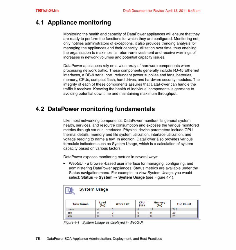
7901ch04.fm Draft Document for Review April 13, 2011 6:45 am
4.1 Appliance monitoring
Monitoring the health and capacity of DataPower appliances will ensure that they are ready to perform the functions for which they are configured. Monitoring not only notifies administrators of exceptions, it also provides trending analysis for managing the appliances and their capacity utilization over time, thus enabling the organization to maximize its return-on-investment and receive warnings of increases in network volumes and potential capacity issues.
DataPower appliances rely on a wide array of hardware components when processing network traffic. These components generally include RJ-45 Ethernet interfaces, a DB-9 serial port, redundant power supplies and fans, batteries, memory, CPUs, compact flash, hard drives, and hardware security modules. The integrity of each of these components assures that DataPower can handle the traffic it receives. Knowing the health of individual components is germane to avoiding potential downtime and maintaining maximum throughput.
4.2 DataPower monitoring fundamentals
Like most networking components, DataPower monitors its general system health, services, and resource consumption and exposes the various monitored metrics through various interfaces. Physical device parameters include CPU thermal details, memory and file system utilization, interface utilization, and voltage reading to name a few. In addition, DataPower also provides various formulaic indicators such as System Usage, which is a calculation of system capacity based on various factors.
DataPower exposes monitoring metrics in several ways:
� WebGUI - a browser-based user interface for managing, configuring, and administering DataPower appliances. Status metrics are available under the Status navigation menu. For example, to view System Usage, you would select: Status System System Usage (see Figure 4-1).
Figure 4-1 System Usage as displayed in WebGUI
78 DataPower SOA Appliance Administration, Deployment, and Best Practices
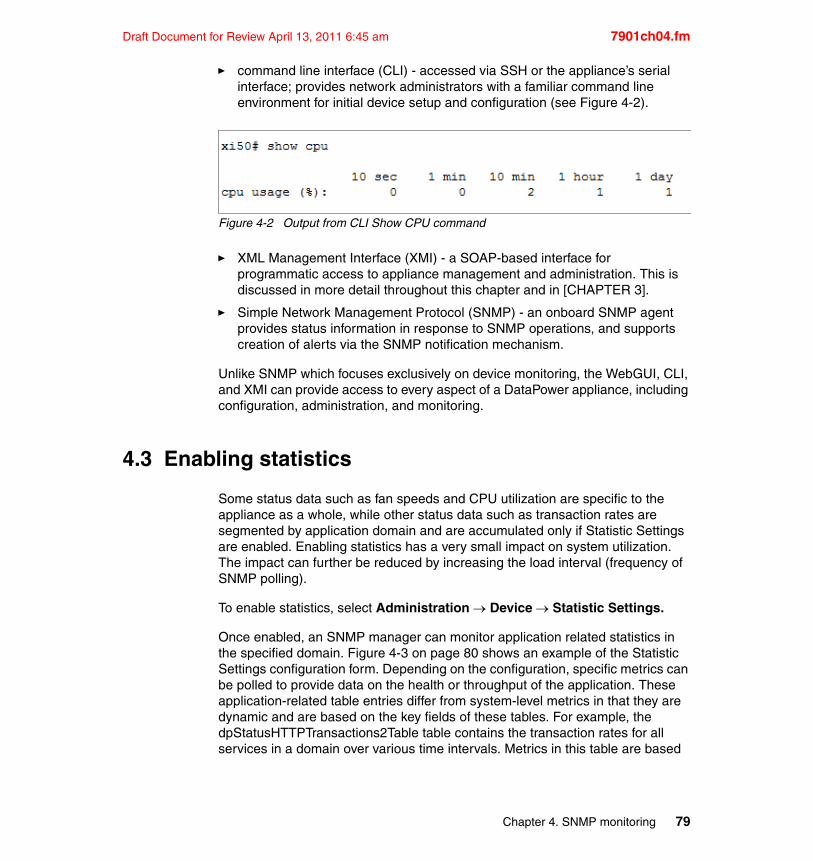
Draft Document for Review April 13, 2011 6:45 am 7901ch04.fm
� command line interface (CLI) - accessed via SSH or the appliance’s serial interface; provides network administrators with a familiar command line environment for initial device setup and configuration (see Figure 4-2).
Figure 4-2 Output from CLI Show CPU command
� XML Management Interface (XMI) - a SOAP-based interface for programmatic access to appliance management and administration. This is discussed in more detail throughout this chapter and in [CHAPTER 3].
� Simple Network Management Protocol (SNMP) - an onboard SNMP agent provides status information in response to SNMP operations, and supports creation of alerts via the SNMP notification mechanism.
Unlike SNMP which focuses exclusively on device monitoring, the WebGUI, CLI, and XMI can provide access to every aspect of a DataPower appliance, including configuration, administration, and monitoring.
4.3 Enabling statistics
Some status data such as fan speeds and CPU utilization are specific to the appliance as a whole, while other status data such as transaction rates are segmented by application domain and are accumulated only if Statistic Settings are enabled. Enabling statistics has a very small impact on system utilization. The impact can further be reduced by increasing the load interval (frequency of SNMP polling).
To enable statistics, select Administration Device Statistic Settings.
Once enabled, an SNMP manager can monitor application related statistics in the specified domain. Figure 4-3 on page 80 shows an example of the Statistic Settings configuration form. Depending on the configuration, specific metrics can be polled to provide data on the health or throughput of the application. These application-related table entries differ from system-level metrics in that they are dynamic and are based on the key fields of these tables. For example, the dpStatusHTTPTransactions2Table table contains the transaction rates for all services in a domain over various time intervals. Metrics in this table are based
Chapter 4. SNMP monitoring 79
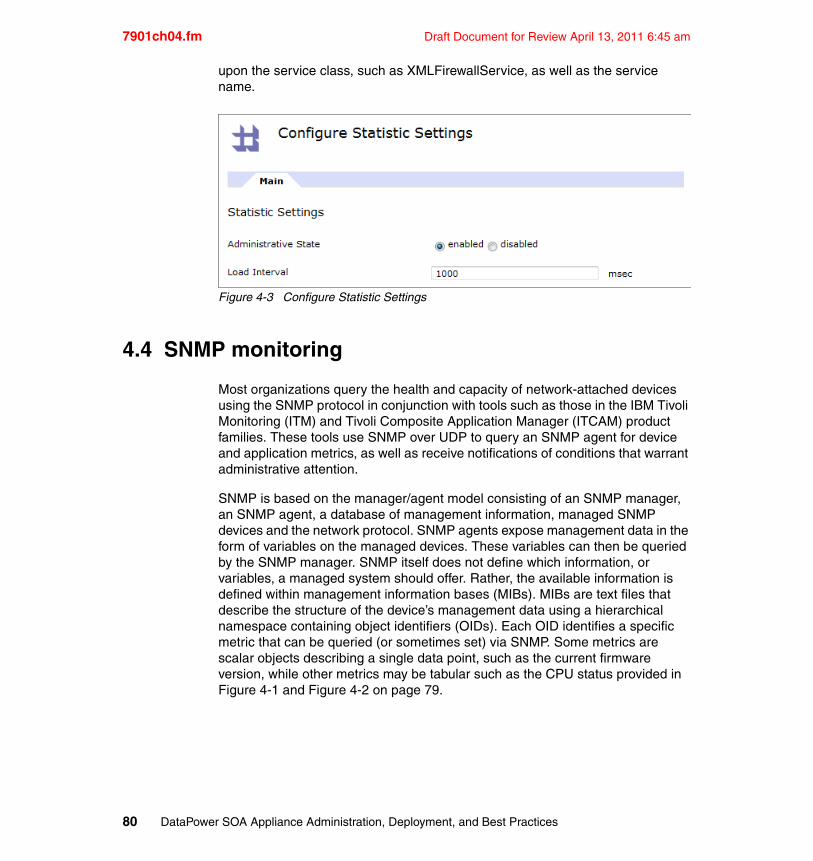
7901ch04.fm Draft Document for Review April 13, 2011 6:45 am
upon the service class, such as XMLFirewallService, as well as the service name.
Figure 4-3 Configure Statistic Settings
4.4 SNMP monitoring
Most organizations query the health and capacity of network-attached devices using the SNMP protocol in conjunction with tools such as those in the IBM Tivoli Monitoring (ITM) and Tivoli Composite Application Manager (ITCAM) product families. These tools use SNMP over UDP to query an SNMP agent for device and application metrics, as well as receive notifications of conditions that warrant administrative attention.
SNMP is based on the manager/agent model consisting of an SNMP manager, an SNMP agent, a database of management information, managed SNMP devices and the network protocol. SNMP agents expose management data in the form of variables on the managed devices. These variables can then be queried by the SNMP manager. SNMP itself does not define which information, or variables, a managed system should offer. Rather, the available information is defined within management information bases (MIBs). MIBs are text files that describe the structure of the device’s management data using a hierarchical namespace containing object identifiers (OIDs). Each OID identifies a specific metric that can be queried (or sometimes set) via SNMP. Some metrics are scalar objects describing a single data point, such as the current firmware version, while other metrics may be tabular such as the CPU status provided in Figure 4-1 and Figure 4-2 on page 79.
80 DataPower SOA Appliance Administration, Deployment, and Best Practices
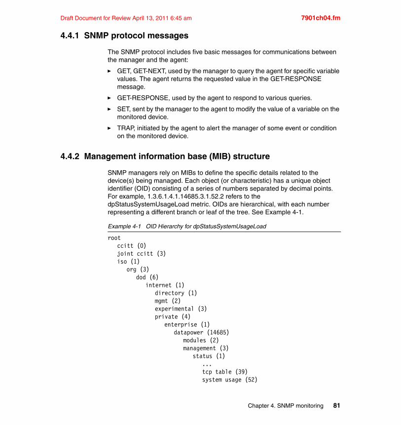
Draft Document for Review April 13, 2011 6:45 am 7901ch04.fm
4.4.1 SNMP protocol messages
The SNMP protocol includes five basic messages for communications between the manager and the agent:
� GET, GET-NEXT, used by the manager to query the agent for specific variable values. The agent returns the requested value in the GET-RESPONSE message.
� GET-RESPONSE, used by the agent to respond to various queries.
� SET, sent by the manager to the agent to modify the value of a variable on the monitored device.
� TRAP, initiated by the agent to alert the manager of some event or condition on the monitored device.
4.4.2 Management information base (MIB) structure
SNMP managers rely on MIBs to define the specific details related to the device(s) being managed. Each object (or characteristic) has a unique object identifier (OID) consisting of a series of numbers separated by decimal points. For example, 1.3.6.1.4.1.14685.3.1.52.2 refers to the dpStatusSystemUsageLoad metric. OIDs are hierarchical, with each number representing a different branch or leaf of the tree. See Example 4-1.
Example 4-1 OID Hierarchy for dpStatusSystemUsageLoad
rootccitt (0)joint ccitt (3)iso (1)
org (3)dod (6)
internet (1)directory (1)mgmt (2)experimental (3)private (4)
enterprise (1)datapower (14685)
modules (2)management (3)
status (1)...tcp table (39)system usage (52)
Chapter 4. SNMP monitoring 81
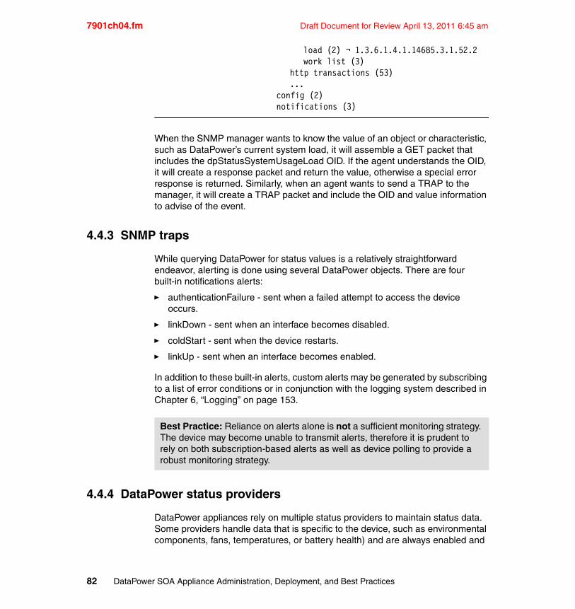
7901ch04.fm Draft Document for Review April 13, 2011 6:45 am
load (2) ¬ 1.3.6.1.4.1.14685.3.1.52.2work list (3)
http transactions (53)...
config (2)notifications (3)
When the SNMP manager wants to know the value of an object or characteristic, such as DataPower’s current system load, it will assemble a GET packet that includes the dpStatusSystemUsageLoad OID. If the agent understands the OID, it will create a response packet and return the value, otherwise a special error response is returned. Similarly, when an agent wants to send a TRAP to the manager, it will create a TRAP packet and include the OID and value information to advise of the event.
4.4.3 SNMP traps
While querying DataPower for status values is a relatively straightforward endeavor, alerting is done using several DataPower objects. There are four built-in notifications alerts:
� authenticationFailure - sent when a failed attempt to access the device occurs.
� linkDown - sent when an interface becomes disabled.
� coldStart - sent when the device restarts.
� linkUp - sent when an interface becomes enabled.
In addition to these built-in alerts, custom alerts may be generated by subscribing to a list of error conditions or in conjunction with the logging system described in Chapter 6, “Logging” on page 153.
4.4.4 DataPower status providers
DataPower appliances rely on multiple status providers to maintain status data. Some providers handle data that is specific to the device, such as environmental components, fans, temperatures, or battery health) and are always enabled and
Best Practice: Reliance on alerts alone is not a sufficient monitoring strategy. The device may become unable to transmit alerts, therefore it is prudent to rely on both subscription-based alerts as well as device polling to provide a robust monitoring strategy.
82 DataPower SOA Appliance Administration, Deployment, and Best Practices
Draft Document for Review April 13, 2011 6:45 am 7901ch04.fm
associated with the default domain. Other status providers are application domain specific, such as those that measure service transaction rates. These status providers may be further segmented by XML-Manager or DataPower service.
While the device-level data is automatically enabled, transaction data such as transaction rates or transaction times, must be explicitly enabled (it is disabled by default). There are exceptions to this generalization - for example, CPU status requires statistic enablement, while System Load does not. Each domain must have its individual Statistics setting enabled to provide domain-specific status.
4.4.5 SNMP security
SNMP, originally developed in the late 80’s, has undergone several redevelopments with focus on performance and security improvements. A weak authentication and access control model has been a key factor in the continual evolution of SNMP. This section discusses the various SNMP versions and their security model.
SNMP security historySNMP version 1 (SNMPv1), the initial implementation of SNMP, required authentication of clients using a simple “community string”. This community string acted effectively as a password, which is transmitted between the manager and the agent in cleartext. For read-only communities, the name public is often used. So long as the manager provided a community name of public, it would have complete access to monitoring data. The community name of private was often used for read-write access. This weak form of security required a water tight management network infrastructure to prevent unauthorized access, especially to read-write communities.
SNMP version 2 (SNMPv2) enhanced version 1 by adding improvements in the areas of performance, security, confidentiality, and manager-to-manager communications. However, the party-based security enhancements in version 2 were viewed by many as overly complex and was not widely accepted.
Community-Based Simple Network Management Protocol version 2 (SNMPv2c) was based on the enhanced SNMPv2 but without the controversial security model. Rather it re-introduced the simple community-based security model found in SNMPv1. While officially only a “Draft Standard”, this is widely considered the de facto SNMP v2 standard. Like SNMPv1, this version depends on a secure management network infrastructure.
SNMP version 3 (SNMPv3) added new security and remote configuration functionality, including password authentication, packet signing, and
Chapter 4. SNMP monitoring 83
7901ch04.fm Draft Document for Review April 13, 2011 6:45 am
encryption/decryption. The Internet Engineering Task Force (IETF) recognizes SNMPv3 as the current standard version and has designated it as a full Internet Standard. The IETF considers earlier versions to be obsolete.
Community-based security (SNMPv1 & SNMPv2c)An SNMP community is the name of the group that devices and managers belong to. It is not necessarily unique amongst devices, nor does a device have to belong to a single community. The community name is used to identify the group. SNMP agents will not respond to requests from managers that do not belong to one of its communities. Communities are further designated as read-only or read-write. It’s important to realize that community names are transmitted in cleartext, therefore they are considered weak forms of security and offer little in the form of protection. Packets are neither signed nor encrypted.
Authenticated and private security (SNMPv3)SNMPv3 security resolves the lack of security in earlier versions by adding support for authenticating the manager, digitally signing transmitted packets, and optionally encrypting the packets transmitted between the agent and the manager.
In SNMPv3, authentication actually represents both authentication of the manager accessing the agent as well as the creation of a digest (digital signature) for each packet that is transmitted between the manager and the agent. Handshaking during the initial contact between the manager and the agent includes authenticating the user and then exchanging a secret authentication key. This is then used during subsequent message digest creation and packet encryption/decryption.
A message digest is created for each packet using a combination of the Keyed Hashing for Message Authentication (HMAC) algorithm, and either the Message Digest 5 (MD5) or the Secure Hash Algorithm 1 (SHA-1). When either the manager or the agent receives a message, they calculate a message digest and compare it with the received one. If the digest does not match, the packet is not authenticated and it is dropped. If privacy is configured, packets are encrypted using the Cipher Block Chaining mode to the Data Encryption Standard (CBC-DES) algorithm.
SNMPv3 security modelsSNMPv3 offers three security models:
� No Authentication, No Privacy - Essentially unsecured.
� Authentication, No Privacy - the user is authenticated and a secret key is used to generate a message digest (signature) for each SNMP packet. Packets are not encrypted.
84 DataPower SOA Appliance Administration, Deployment, and Best Practices
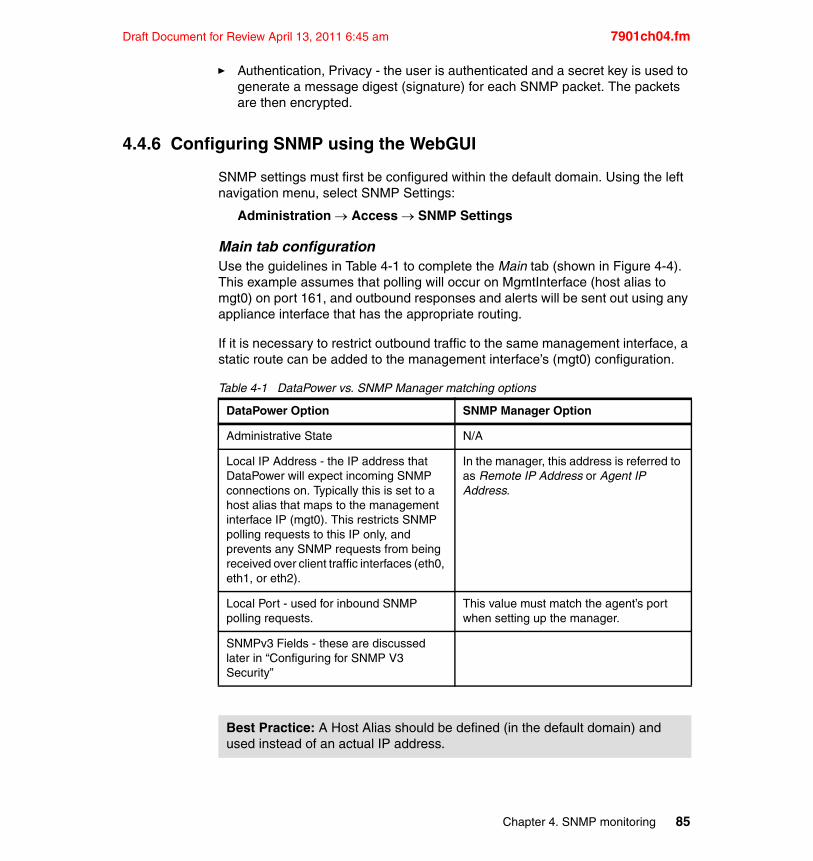
Draft Document for Review April 13, 2011 6:45 am 7901ch04.fm
� Authentication, Privacy - the user is authenticated and a secret key is used to generate a message digest (signature) for each SNMP packet. The packets are then encrypted.
4.4.6 Configuring SNMP using the WebGUI
SNMP settings must first be configured within the default domain. Using the left navigation menu, select SNMP Settings:
Administration Access SNMP Settings
Main tab configurationUse the guidelines in Table 4-1 to complete the Main tab (shown in Figure 4-4). This example assumes that polling will occur on MgmtInterface (host alias to mgt0) on port 161, and outbound responses and alerts will be sent out using any appliance interface that has the appropriate routing.
If it is necessary to restrict outbound traffic to the same management interface, a static route can be added to the management interface’s (mgt0) configuration.
Table 4-1 DataPower vs. SNMP Manager matching options
DataPower Option SNMP Manager Option
Administrative State N/A
Local IP Address - the IP address that DataPower will expect incoming SNMP connections on. Typically this is set to a host alias that maps to the management interface IP (mgt0). This restricts SNMP polling requests to this IP only, and prevents any SNMP requests from being received over client traffic interfaces (eth0, eth1, or eth2).
In the manager, this address is referred to as Remote IP Address or Agent IP Address.
Local Port - used for inbound SNMP polling requests.
This value must match the agent’s port when setting up the manager.
SNMPv3 Fields - these are discussed later in “Configuring for SNMP V3 Security”
Best Practice: A Host Alias should be defined (in the default domain) and used instead of an actual IP address.
Chapter 4. SNMP monitoring 85
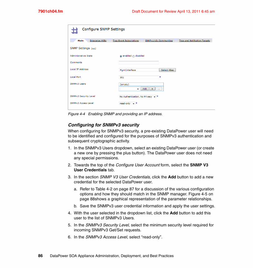
7901ch04.fm Draft Document for Review April 13, 2011 6:45 am
Figure 4-4 Enabling SNMP and providing an IP address.
Configuring for SNMPv3 securityWhen configuring for SNMPv3 security, a pre-existing DataPower user will need to be identified and configured for the purposes of SNMPv3 authentication and subsequent cryptographic activity.
1. In the SNMPv3 Users dropdown, select an existing DataPower user (or create a new one by pressing the plus button). The DataPower user does not need any special permissions.
2. Towards the top of the Configure User Account form, select the SNMP V3 User Credentials tab.
3. In the section SNMP V3 User Credentials, click the Add button to add a new credential for the selected DataPower user.
a. Refer to Table 4-2 on page 87 for a discussion of the various configuration options and how they should match in the SNMP manager. Figure 4-5 on page 88shows a graphical representation of the parameter relationships.
b. Save the SNMPv3 user credential information and apply the user settings.
4. With the user selected in the dropdown list, click the Add button to add this user to the list of SNMPv3 Users.
5. In the SNMPv3 Security Level, select the minimum security level required for incoming SNMPv3 Get/Set requests.
6. In the SNMPv3 Access Level, select “read-only”.
86 DataPower SOA Appliance Administration, Deployment, and Best Practices
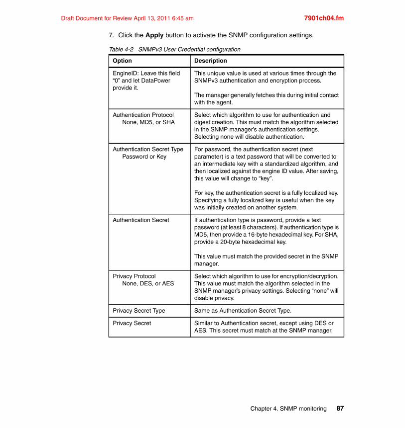
Draft Document for Review April 13, 2011 6:45 am 7901ch04.fm
7. Click the Apply button to activate the SNMP configuration settings.
Table 4-2 SNMPv3 User Credential configuration
Option Description
EngineID: Leave this field “0” and let DataPower provide it.
This unique value is used at various times through the SNMPv3 authentication and encryption process.
The manager generally fetches this during initial contact with the agent.
Authentication ProtocolNone, MD5, or SHA
Select which algorithm to use for authentication and digest creation. This must match the algorithm selected in the SNMP manager’s authentication settings. Selecting none will disable authentication.
Authentication Secret TypePassword or Key
For password, the authentication secret (next parameter) is a text password that will be converted to an intermediate key with a standardized algorithm, and then localized against the engine ID value. After saving, this value will change to “key”.
For key, the authentication secret is a fully localized key. Specifying a fully localized key is useful when the key was initially created on another system.
Authentication Secret If authentication type is password, provide a text password (at least 8 characters). If authentication type is MD5, then provide a 16-byte hexadecimal key. For SHA, provide a 20-byte hexadecimal key.
This value must match the provided secret in the SNMP manager.
Privacy ProtocolNone, DES, or AES
Select which algorithm to use for encryption/decryption. This value must match the algorithm selected in the SNMP manager’s privacy settings. Selecting “none” will disable privacy.
Privacy Secret Type Same as Authentication Secret Type.
Privacy Secret Similar to Authentication secret, except using DES or AES. This secret must match at the SNMP manager.
Chapter 4. SNMP monitoring 87
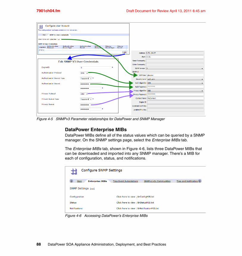
7901ch04.fm Draft Document for Review April 13, 2011 6:45 am
Figure 4-5 SNMPv3 Parameter relationships for DataPower and SNMP Manager
DataPower Enterprise MIBsDataPower MIBs define all of the status values which can be queried by a SNMP manager. On the SNMP settings page, select the Enterprise MIBs tab.
The Enterprise MIBs tab, shown in Figure 4-6, lists three DataPower MIBs that can be downloaded and imported into any SNMP manager. There’s a MIB for each of configuration, status, and notifications.
Figure 4-6 Accessing DataPower’s Enterprise MIBs
88 DataPower SOA Appliance Administration, Deployment, and Best Practices
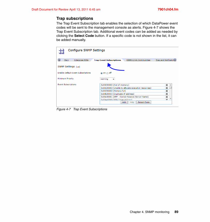
Draft Document for Review April 13, 2011 6:45 am 7901ch04.fm
Trap subscriptionsThe Trap Event Subscription tab enables the selection of which DataPower event codes will be sent to the management console as alerts. Figure 4-7 shows the Trap Event Subscription tab. Additional event codes can be added as needed by clicking the Select Code button. If a specific code is not shown in the list, it can be added manually.
Figure 4-7 Trap Event Subscriptions
Chapter 4. SNMP monitoring 89
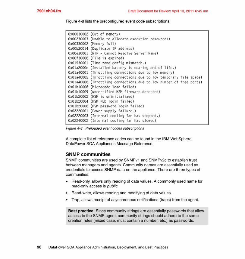
7901ch04.fm Draft Document for Review April 13, 2011 6:45 am
Figure 4-8 lists the preconfigured event code subscriptions.
Figure 4-8 Preloaded event codes subscriptions
A complete list of reference codes can be found in the IBM WebSphere DataPower SOA Appliances Message Reference.
SNMP communitiesSNMP communities are used by SNMPv1 and SNMPv2c to establish trust between managers and agents. Community names are essentially used as credentials to access SNMP data on the appliance. There are three types of communities:
� Read-only, allows only reading of data values. A commonly used name for read-only access is public.
� Read-write, allows reading and modifying of data values.
� Trap, allows receipt of asynchronous notifications (traps) from the agent.
0x00030002 (Out of memory)0x00230003 (Unable to allocate execution resources)0x00330002 (Memory full)0x00b30014 (Duplicate IP address)0x00e30001 (NTP - Cannot Resolve Server Name)0x00f30008 (File is expired)0x01530001 (Time zone config mismatch.)0x01a2000e (Installed battery is nearing end of life.)0x01a40001 (Throttling connections due to low memory)0x01a40005 (Throttling connections due to low temporary file space)0x01a40008 (Throttling connections due to low number of free ports)0x01b10006 (Microcode load failed)0x01b10009 (uncertified HSM firmware detected)0x01b20002 (HSM is uninitialized)0x01b20004 (HSM PED login failed)0x01b20008 (HSM password login failed)0x02220001 (Power supply failure.)0x02220003 (Internal cooling fan has stopped.)0x02240002 (Internal cooling fan has slowed)
Best practice: Since community strings are essentially passwords that allow access to the SNMP agent, community strings should adhere to the same creation rules (mixed case, must contain a number, etc.) as passwords.
90 DataPower SOA Appliance Administration, Deployment, and Best Practices
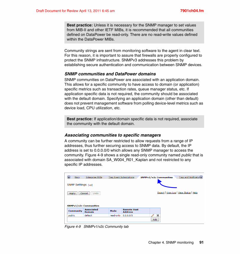
Draft Document for Review April 13, 2011 6:45 am 7901ch04.fm
Community strings are sent from monitoring software to the agent in clear text. For this reason, it is important to assure that firewalls are properly configured to protect the SNMP infrastructure. SNMPv3 addresses this problem by establishing secure authentication and communication between SNMP devices.
SNMP communities and DataPower domainsSNMP communities on DataPower are associated with an application domain. This allows for a specific community to have access to domain (or application) specific metrics such as transaction rates, queue manager status, etc. If application specific data is not required, the community should be associated with the default domain. Specifying an application domain (other than default) does not prevent management software from polling device-level metrics such as device load, CPU utilization, etc.
Associating communities to specific managersA community can be further restricted to allow requests from a range of IP addresses, thus further securing access to SNMP data. By default, the IP address is set to 0.0.0.0/0 which allows any SNMP manager to access the community. Figure 4-9 shows a single read-only community named public that is associated with domain SA_W004_R01_Kaplan and not restricted to any specific IP addresses.
Figure 4-9 SNMPv1/v2c Community tab
Best practice: Unless it is necessary for the SNMP manager to set values from MIB-II and other IETF MIBs, it is recommended that all communities defined on DataPower be read-only. There are no read-write values defined within the DataPower MIBs.
Best practice: If application/domain specific data is not required, associate the community with the default domain.
Chapter 4. SNMP monitoring 91
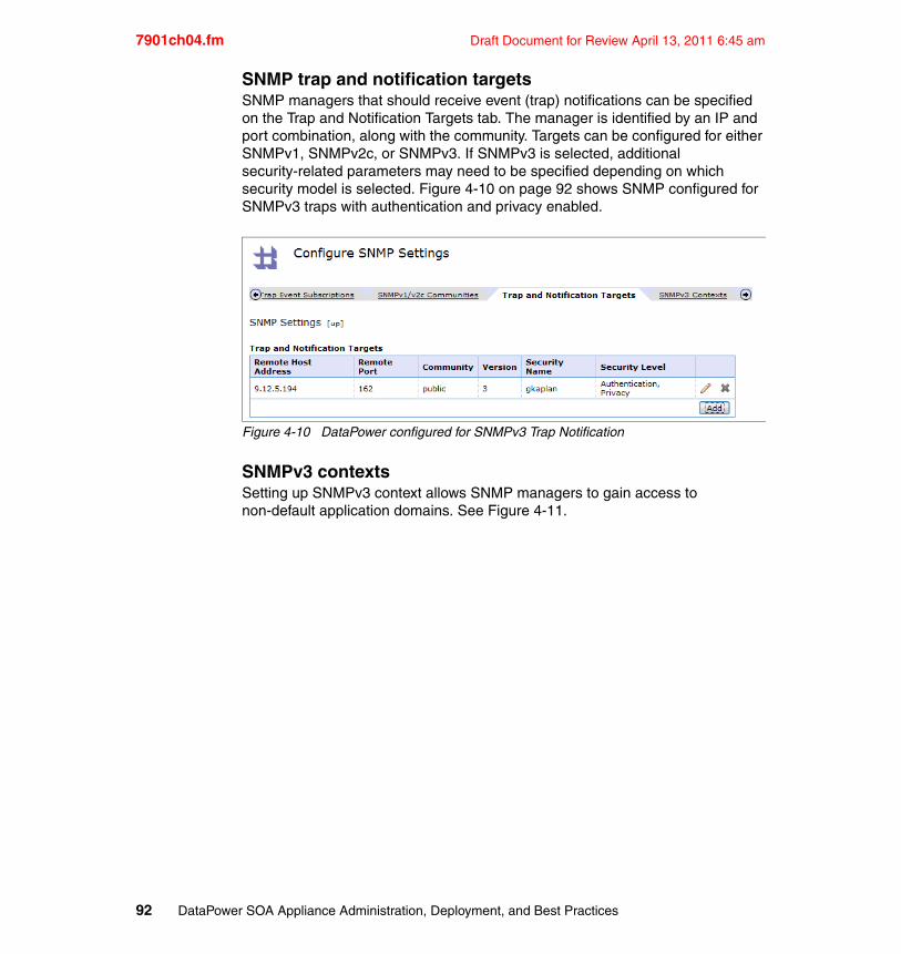
7901ch04.fm Draft Document for Review April 13, 2011 6:45 am
SNMP trap and notification targetsSNMP managers that should receive event (trap) notifications can be specified on the Trap and Notification Targets tab. The manager is identified by an IP and port combination, along with the community. Targets can be configured for either SNMPv1, SNMPv2c, or SNMPv3. If SNMPv3 is selected, additional security-related parameters may need to be specified depending on which security model is selected. Figure 4-10 on page 92 shows SNMP configured for SNMPv3 traps with authentication and privacy enabled.
Figure 4-10 DataPower configured for SNMPv3 Trap Notification
SNMPv3 contextsSetting up SNMPv3 context allows SNMP managers to gain access to non-default application domains. See Figure 4-11.
92 DataPower SOA Appliance Administration, Deployment, and Best Practices
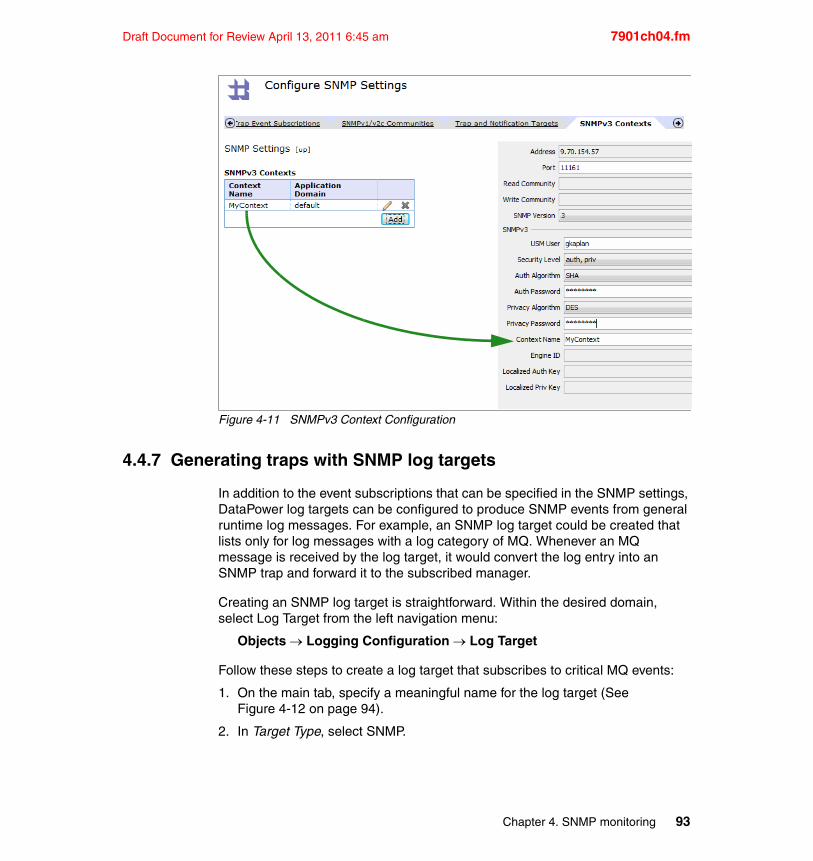
Draft Document for Review April 13, 2011 6:45 am 7901ch04.fm
Figure 4-11 SNMPv3 Context Configuration
4.4.7 Generating traps with SNMP log targets
In addition to the event subscriptions that can be specified in the SNMP settings, DataPower log targets can be configured to produce SNMP events from general runtime log messages. For example, an SNMP log target could be created that lists only for log messages with a log category of MQ. Whenever an MQ message is received by the log target, it would convert the log entry into an SNMP trap and forward it to the subscribed manager.
Creating an SNMP log target is straightforward. Within the desired domain, select Log Target from the left navigation menu:
Objects Logging Configuration Log Target
Follow these steps to create a log target that subscribes to critical MQ events:
1. On the main tab, specify a meaningful name for the log target (See Figure 4-12 on page 94).
2. In Target Type, select SNMP.
Chapter 4. SNMP monitoring 93
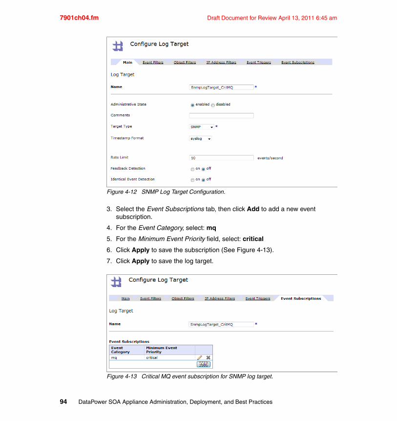
7901ch04.fm Draft Document for Review April 13, 2011 6:45 am
Figure 4-12 SNMP Log Target Configuration.
3. Select the Event Subscriptions tab, then click Add to add a new event subscription.
4. For the Event Category, select: mq
5. For the Minimum Event Priority field, select: critical
6. Click Apply to save the subscription (See Figure 4-13).
7. Click Apply to save the log target.
Figure 4-13 Critical MQ event subscription for SNMP log target.
94 DataPower SOA Appliance Administration, Deployment, and Best Practices
Draft Document for Review April 13, 2011 6:45 am 7901ch04.fm
Whenever a critical MQ message is logged within the domain, the log message will be used as the basis for an SNMP trap. Any managers subscribing for traps will receive the notification.
4.5 Monitoring via the XML Management Interface
While SNMP provides a standards-based approach to monitoring, and the WebGUI and CLI are convenient tools to fetch status information interactively, the XML Management Interface (XMI) can be used to programmatically monitor and configure DataPower. For example, an application can request status information from DataPower by issuing a dp:get-status SOAP request to the XMI, and perform some operation or configuration modification based on the value in the SOAP response.
The XML Management Interface exposes several endpoints which are accessible via URI. One such endpoint is the SOAP Configuration Management (SOMA) interface, a service that provides a set of operations for both monitoring and configuring DataPower appliances. The Web Services Description Language (WSDLs) and schemas for SOMA can be found in DataPower’s store: directory.
Table 4-3 SOMA-related WSDLs and XSDs found in store: directory
Enabling the XML Management InterfaceIn order to issue requests against the XML Management Interface, it must be enabled and configured for the appropriate request types. XMI configuration options can be found in the left navigation menu:
Network Management XML Management Interface
Once selected, the XMI can be enabled and the network-related settings can be customized as necessary (see Figure 4-14). Table 4-4 on page 96 discusses the various configuration options available.
File Name Description
store:///xml-mgmt.wsdl SOMA WSDL
store:///xml-mgmt-ops.xsd Schema describing various operations and types
store:///xml-mgmt.xsd Schema describing elements and options
Chapter 4. SNMP monitoring 95
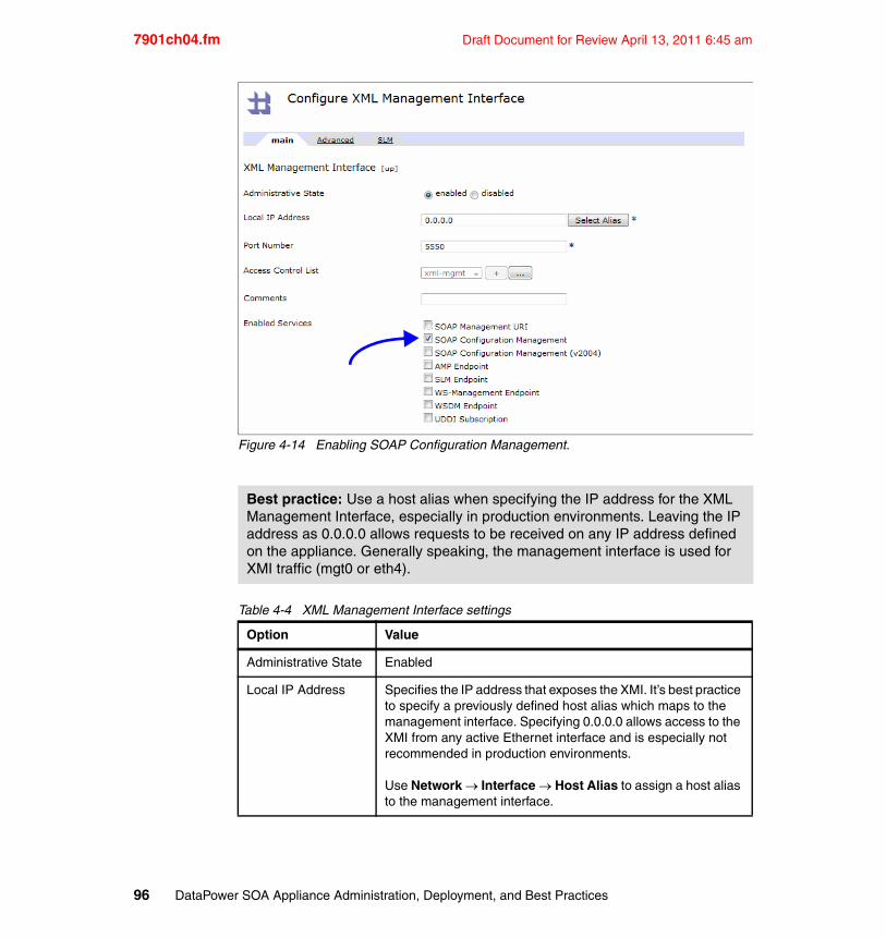
7901ch04.fm Draft Document for Review April 13, 2011 6:45 am
Figure 4-14 Enabling SOAP Configuration Management.
Table 4-4 XML Management Interface settings
Best practice: Use a host alias when specifying the IP address for the XML Management Interface, especially in production environments. Leaving the IP address as 0.0.0.0 allows requests to be received on any IP address defined on the appliance. Generally speaking, the management interface is used for XMI traffic (mgt0 or eth4).
Option Value
Administrative State Enabled
Local IP Address Specifies the IP address that exposes the XMI. It’s best practice to specify a previously defined host alias which maps to the management interface. Specifying 0.0.0.0 allows access to the XMI from any active Ethernet interface and is especially not recommended in production environments.
Use Network Interface Host Alias to assign a host alias to the management interface.
96 DataPower SOA Appliance Administration, Deployment, and Best Practices
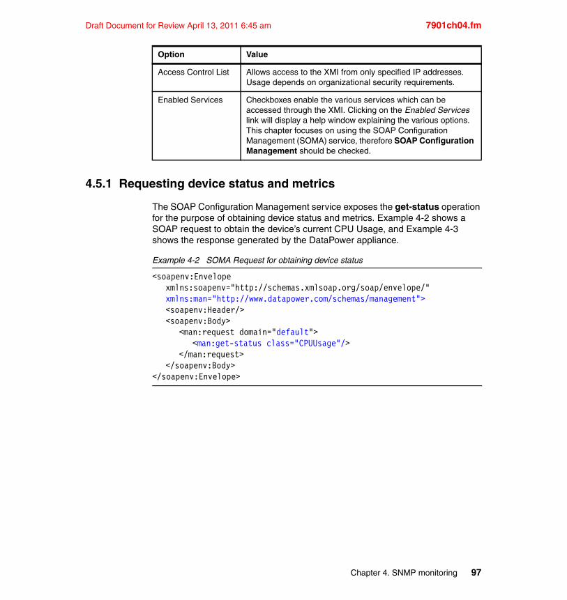
Draft Document for Review April 13, 2011 6:45 am 7901ch04.fm
4.5.1 Requesting device status and metrics
The SOAP Configuration Management service exposes the get-status operation for the purpose of obtaining device status and metrics. Example 4-2 shows a SOAP request to obtain the device’s current CPU Usage, and Example 4-3 shows the response generated by the DataPower appliance.
Example 4-2 SOMA Request for obtaining device status
<soapenv:Envelopexmlns:soapenv="http://schemas.xmlsoap.org/soap/envelope/" xmlns:man="http://www.datapower.com/schemas/management"><soapenv:Header/><soapenv:Body>
<man:request domain="default"><man:get-status class="CPUUsage"/>
</man:request></soapenv:Body>
</soapenv:Envelope>
Access Control List Allows access to the XMI from only specified IP addresses. Usage depends on organizational security requirements.
Enabled Services Checkboxes enable the various services which can be accessed through the XMI. Clicking on the Enabled Services link will display a help window explaining the various options. This chapter focuses on using the SOAP Configuration Management (SOMA) service, therefore SOAP Configuration Management should be checked.
Option Value
Chapter 4. SNMP monitoring 97
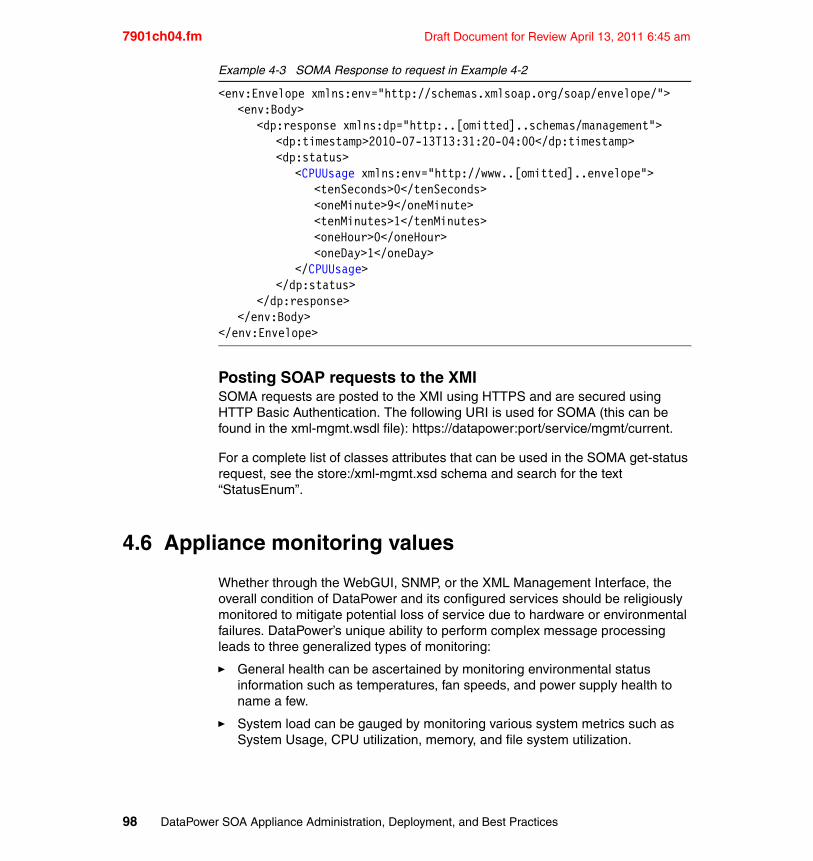
7901ch04.fm Draft Document for Review April 13, 2011 6:45 am
Example 4-3 SOMA Response to request in Example 4-2
<env:Envelope xmlns:env="http://schemas.xmlsoap.org/soap/envelope/"><env:Body>
<dp:response xmlns:dp="http:..[omitted]..schemas/management"><dp:timestamp>2010-07-13T13:31:20-04:00</dp:timestamp><dp:status>
<CPUUsage xmlns:env="http://www..[omitted]..envelope"><tenSeconds>0</tenSeconds><oneMinute>9</oneMinute><tenMinutes>1</tenMinutes><oneHour>0</oneHour><oneDay>1</oneDay>
</CPUUsage></dp:status>
</dp:response></env:Body>
</env:Envelope>
Posting SOAP requests to the XMISOMA requests are posted to the XMI using HTTPS and are secured using HTTP Basic Authentication. The following URI is used for SOMA (this can be found in the xml-mgmt.wsdl file): https://datapower:port/service/mgmt/current.
For a complete list of classes attributes that can be used in the SOMA get-status request, see the store:/xml-mgmt.xsd schema and search for the text “StatusEnum”.
4.6 Appliance monitoring values
Whether through the WebGUI, SNMP, or the XML Management Interface, the overall condition of DataPower and its configured services should be religiously monitored to mitigate potential loss of service due to hardware or environmental failures. DataPower’s unique ability to perform complex message processing leads to three generalized types of monitoring:
� General health can be ascertained by monitoring environmental status information such as temperatures, fan speeds, and power supply health to name a few.
� System load can be gauged by monitoring various system metrics such as System Usage, CPU utilization, memory, and file system utilization.
98 DataPower SOA Appliance Administration, Deployment, and Best Practices

Draft Document for Review April 13, 2011 6:45 am 7901ch04.fm
� Processing throughput can be determined by analyzing network interface consumption and transaction statistics.
DataPower appliances expose a wealth of information that can be used to support monitoring of these topics and assess the overall health of DataPower and its configuration. The remainder of this section describes some of the key status values which should be monitored. For each monitored value described, a table is presented that shows the four primary ways of obtaining the status values. The table shows:
� The access path using the left navigation menu in DataPower’s WebGUI.
� The CLI command to enter into a command window (SSH or Serial interface).
� The XMI Status class, describing which values to use for the class attribute in a SOMA request.
� The name of the MIB variable in the Status MIB document which contains the associated value.
4.6.1 General device health and activity monitors
General health and activity monitors ensure that a DataPower appliance is operating within predefined system parameters. The monitoring values in this section are all related to general device health.
System usageSystem Usage is a measurement of the device’s ability to accept additional work. It is a formulaic calculation based on various components of system load, including CPU, memory, and filesystem utilization. System Usage is typically considered the best single indicator of overall system capacity. While it may sometimes spike to 100%, typical values are less than 75%. The secondary work list value is a calculation of internally queued tasks, and is of lesser interest in typical monitoring situations.
Note: The XML examples showing the SOMA responses have been slightly simplified for the purpose of brevity. Specifically, the SOAP Body and Envelope elements have been removed, large repeating elements have been removed (and noted), and some namespaces have been shortened. The XML examples are provided for reference to see exactly what data is returned on the request.
Requests are not shown but a fully functional SOM request can be seen in Example 4-2 on page 97. Replacing the CPUUsage class with the class specified in this section will yield the desired status values.
Chapter 4. SNMP monitoring 99
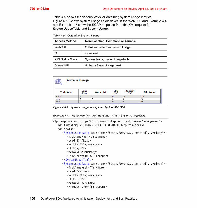
7901ch04.fm Draft Document for Review April 13, 2011 6:45 am
Table 4-5 shows the various ways for obtaining system usage metrics. Figure 4-15 shows system usage as displayed in the WebGUI, and Example 4-4 and Example 4-5 show the SOAP response from the XMI request for SystemUsageTable and SystemUsage.
Table 4-5 Obtaining System Usage
Figure 4-15 System usage as depicted by the WebGUI.
Example 4-4 Response from XMI get-status, class: SystemUsageTable.
<dp:response xmlns:dp="http://www.datapower.com/schemas/management"><dp:timestamp>2010-07-19T14:03:40-04:00</dp:timestamp><dp:status>
<SystemUsageTable xmlns:env="http://www.w3..[omitted]...velope"><TaskName>main</TaskName><Load>13</Load><WorkList>0</WorkList><CPU>0</CPU><Memory>22</Memory><FileCount>109</FileCount>
</SystemUsageTable><SystemUsageTable xmlns:env="http://www.w3..[omitted]...velope">
<TaskName>ssh</TaskName><Load>0</Load><WorkList>0</WorkList><CPU>0</CPU><Memory>0</Memory><FileCount>29</FileCount>
Access Method Menu location, Command or Variable
WebGUI Status System System Usage
CLI show load
XMI Status Class SystemUsage; SystemUsageTable
Status MIB dpStatusSystemUsageLoad
100 DataPower SOA Appliance Administration, Deployment, and Best Practices
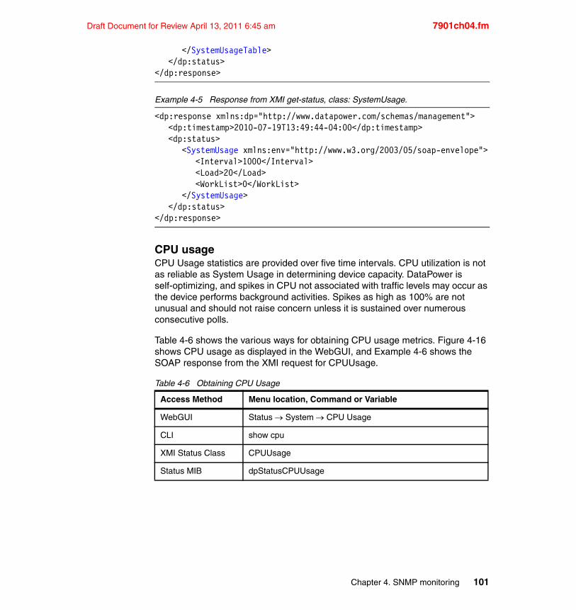
Draft Document for Review April 13, 2011 6:45 am 7901ch04.fm
</SystemUsageTable></dp:status>
</dp:response>
Example 4-5 Response from XMI get-status, class: SystemUsage.
<dp:response xmlns:dp="http://www.datapower.com/schemas/management"><dp:timestamp>2010-07-19T13:49:44-04:00</dp:timestamp><dp:status>
<SystemUsage xmlns:env="http://www.w3.org/2003/05/soap-envelope"><Interval>1000</Interval><Load>20</Load><WorkList>0</WorkList>
</SystemUsage></dp:status>
</dp:response>
CPU usageCPU Usage statistics are provided over five time intervals. CPU utilization is not as reliable as System Usage in determining device capacity. DataPower is self-optimizing, and spikes in CPU not associated with traffic levels may occur as the device performs background activities. Spikes as high as 100% are not unusual and should not raise concern unless it is sustained over numerous consecutive polls.
Table 4-6 shows the various ways for obtaining CPU usage metrics. Figure 4-16 shows CPU usage as displayed in the WebGUI, and Example 4-6 shows the SOAP response from the XMI request for CPUUsage.
Table 4-6 Obtaining CPU Usage
Access Method Menu location, Command or Variable
WebGUI Status System CPU Usage
CLI show cpu
XMI Status Class CPUUsage
Status MIB dpStatusCPUUsage
Chapter 4. SNMP monitoring 101
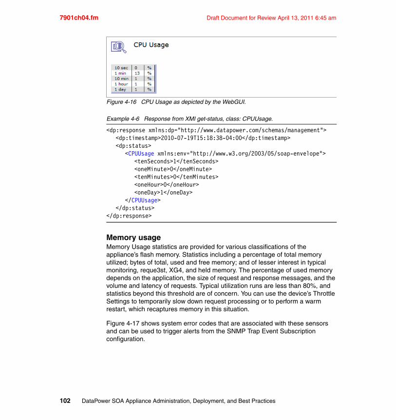
7901ch04.fm Draft Document for Review April 13, 2011 6:45 am
Figure 4-16 CPU Usage as depicted by the WebGUI.
Example 4-6 Response from XMI get-status, class: CPUUsage.
<dp:response xmlns:dp="http://www.datapower.com/schemas/management"><dp:timestamp>2010-07-19T15:18:38-04:00</dp:timestamp><dp:status>
<CPUUsage xmlns:env="http://www.w3.org/2003/05/soap-envelope"><tenSeconds>1</tenSeconds><oneMinute>0</oneMinute><tenMinutes>0</tenMinutes><oneHour>0</oneHour><oneDay>1</oneDay>
</CPUUsage></dp:status>
</dp:response>
Memory usageMemory Usage statistics are provided for various classifications of the appliance’s flash memory. Statistics including a percentage of total memory utilized; bytes of total, used and free memory; and of lesser interest in typical monitoring, reque3st, XG4, and held memory. The percentage of used memory depends on the application, the size of request and response messages, and the volume and latency of requests. Typical utilization runs are less than 80%, and statistics beyond this threshold are of concern. You can use the device’s Throttle Settings to temporarily slow down request processing or to perform a warm restart, which recaptures memory in this situation.
Figure 4-17 shows system error codes that are associated with these sensors and can be used to trigger alerts from the SNMP Trap Event Subscription configuration.
102 DataPower SOA Appliance Administration, Deployment, and Best Practices
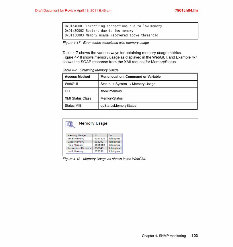
Draft Document for Review April 13, 2011 6:45 am 7901ch04.fm
Figure 4-17 Error codes associated with memory usage
Table 4-7 shows the various ways for obtaining memory usage metrics. Figure 4-18 shows memory usage as displayed in the WebGUI, and Example 4-7 shows the SOAP response from the XMI request for MemoryStatus.
Table 4-7 Obtaining Memory Usage
Figure 4-18 Memory Usage as shown in the WebGUI.
0x01a40001 Throttling connections due to low memory0x01a30002 Restart due to low memory0x01a30003 Memory usage recovered above threshold
Access Method Menu location, Command or Variable
WebGUI Status System Memory Usage
CLI show memory
XMI Status Class MemoryStatus
Status MIB dpStatusMemoryStatus
Chapter 4. SNMP monitoring 103
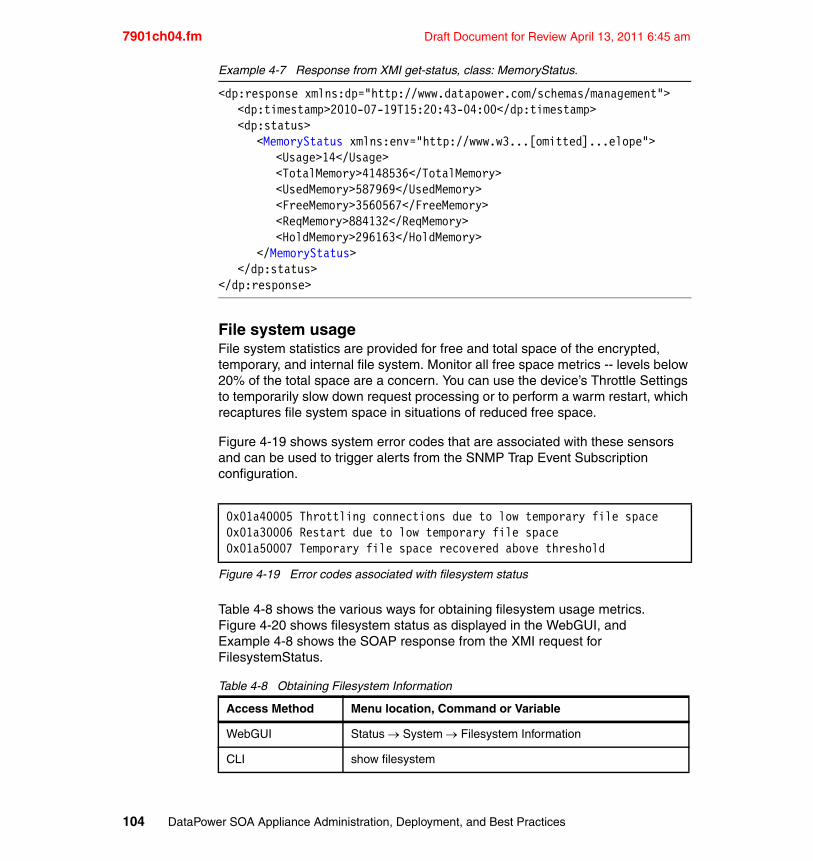
7901ch04.fm Draft Document for Review April 13, 2011 6:45 am
Example 4-7 Response from XMI get-status, class: MemoryStatus.
<dp:response xmlns:dp="http://www.datapower.com/schemas/management"><dp:timestamp>2010-07-19T15:20:43-04:00</dp:timestamp><dp:status>
<MemoryStatus xmlns:env="http://www.w3...[omitted]...elope"><Usage>14</Usage><TotalMemory>4148536</TotalMemory><UsedMemory>587969</UsedMemory><FreeMemory>3560567</FreeMemory><ReqMemory>884132</ReqMemory><HoldMemory>296163</HoldMemory>
</MemoryStatus></dp:status>
</dp:response>
File system usageFile system statistics are provided for free and total space of the encrypted, temporary, and internal file system. Monitor all free space metrics -- levels below 20% of the total space are a concern. You can use the device’s Throttle Settings to temporarily slow down request processing or to perform a warm restart, which recaptures file system space in situations of reduced free space.
Figure 4-19 shows system error codes that are associated with these sensors and can be used to trigger alerts from the SNMP Trap Event Subscription configuration.
Figure 4-19 Error codes associated with filesystem status
Table 4-8 shows the various ways for obtaining filesystem usage metrics. Figure 4-20 shows filesystem status as displayed in the WebGUI, and Example 4-8 shows the SOAP response from the XMI request for FilesystemStatus.
Table 4-8 Obtaining Filesystem Information
0x01a40005 Throttling connections due to low temporary file space0x01a30006 Restart due to low temporary file space0x01a50007 Temporary file space recovered above threshold
Access Method Menu location, Command or Variable
WebGUI Status System Filesystem Information
CLI show filesystem
104 DataPower SOA Appliance Administration, Deployment, and Best Practices
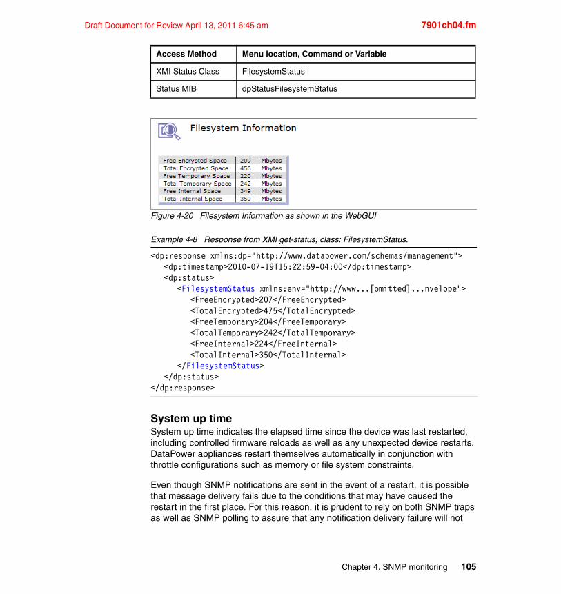
Draft Document for Review April 13, 2011 6:45 am 7901ch04.fm
Figure 4-20 Filesystem Information as shown in the WebGUI
Example 4-8 Response from XMI get-status, class: FilesystemStatus.
<dp:response xmlns:dp="http://www.datapower.com/schemas/management"><dp:timestamp>2010-07-19T15:22:59-04:00</dp:timestamp><dp:status>
<FilesystemStatus xmlns:env="http://www...[omitted]...nvelope"><FreeEncrypted>207</FreeEncrypted><TotalEncrypted>475</TotalEncrypted><FreeTemporary>204</FreeTemporary><TotalTemporary>242</TotalTemporary><FreeInternal>224</FreeInternal><TotalInternal>350</TotalInternal>
</FilesystemStatus></dp:status>
</dp:response>
System up timeSystem up time indicates the elapsed time since the device was last restarted, including controlled firmware reloads as well as any unexpected device restarts. DataPower appliances restart themselves automatically in conjunction with throttle configurations such as memory or file system constraints.
Even though SNMP notifications are sent in the event of a restart, it is possible that message delivery fails due to the conditions that may have caused the restart in the first place. For this reason, it is prudent to rely on both SNMP traps as well as SNMP polling to assure that any notification delivery failure will not
XMI Status Class FilesystemStatus
Status MIB dpStatusFilesystemStatus
Access Method Menu location, Command or Variable
Chapter 4. SNMP monitoring 105
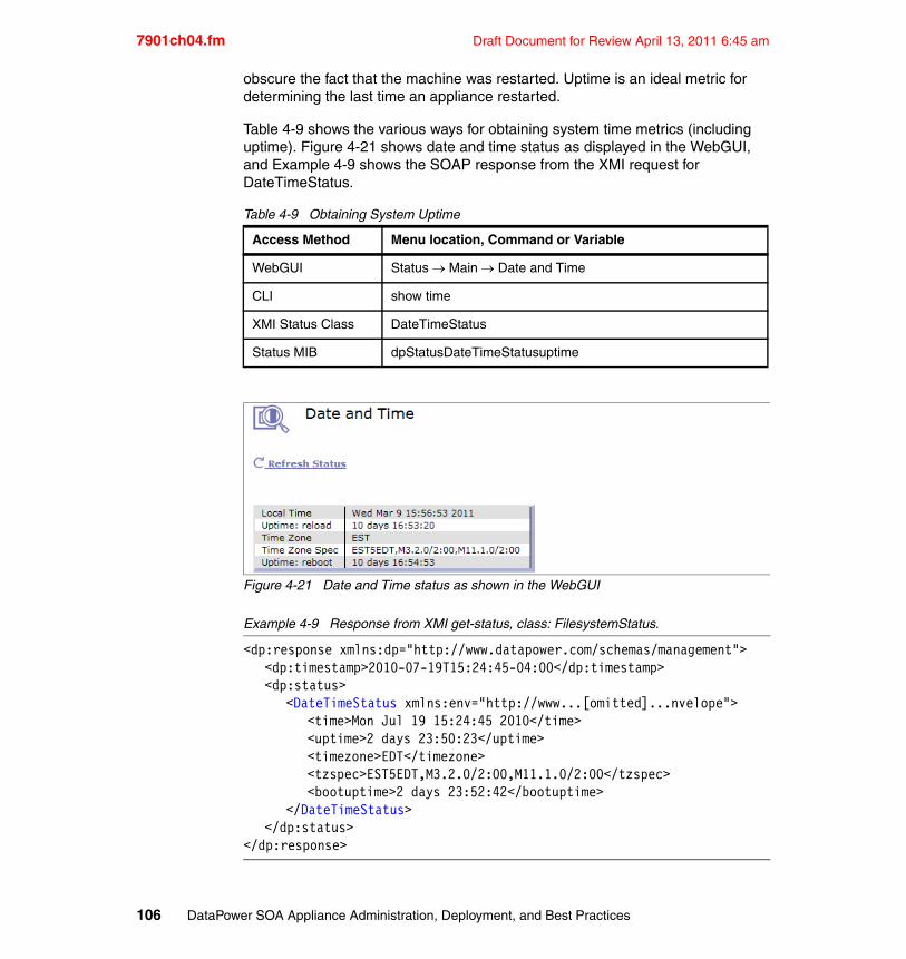
7901ch04.fm Draft Document for Review April 13, 2011 6:45 am
obscure the fact that the machine was restarted. Uptime is an ideal metric for determining the last time an appliance restarted.
Table 4-9 shows the various ways for obtaining system time metrics (including uptime). Figure 4-21 shows date and time status as displayed in the WebGUI, and Example 4-9 shows the SOAP response from the XMI request for DateTimeStatus.
Table 4-9 Obtaining System Uptime
Figure 4-21 Date and Time status as shown in the WebGUI
Example 4-9 Response from XMI get-status, class: FilesystemStatus.
<dp:response xmlns:dp="http://www.datapower.com/schemas/management"><dp:timestamp>2010-07-19T15:24:45-04:00</dp:timestamp><dp:status>
<DateTimeStatus xmlns:env="http://www...[omitted]...nvelope"><time>Mon Jul 19 15:24:45 2010</time><uptime>2 days 23:50:23</uptime><timezone>EDT</timezone><tzspec>EST5EDT,M3.2.0/2:00,M11.1.0/2:00</tzspec><bootuptime>2 days 23:52:42</bootuptime>
</DateTimeStatus></dp:status>
</dp:response>
Access Method Menu location, Command or Variable
WebGUI Status Main Date and Time
CLI show time
XMI Status Class DateTimeStatus
Status MIB dpStatusDateTimeStatusuptime
106 DataPower SOA Appliance Administration, Deployment, and Best Practices
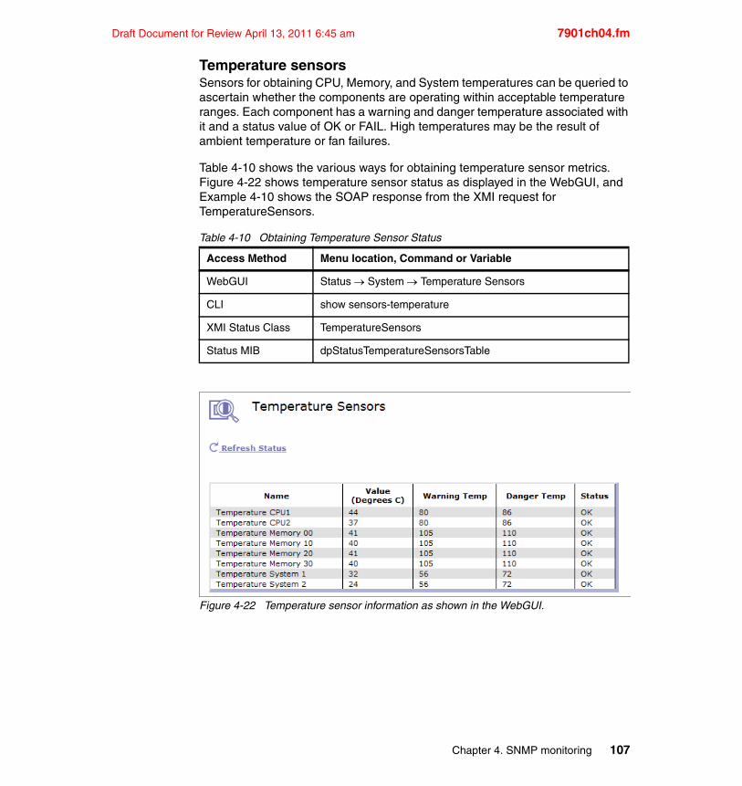
Draft Document for Review April 13, 2011 6:45 am 7901ch04.fm
Temperature sensorsSensors for obtaining CPU, Memory, and System temperatures can be queried to ascertain whether the components are operating within acceptable temperature ranges. Each component has a warning and danger temperature associated with it and a status value of OK or FAIL. High temperatures may be the result of ambient temperature or fan failures.
Table 4-10 shows the various ways for obtaining temperature sensor metrics. Figure 4-22 shows temperature sensor status as displayed in the WebGUI, and Example 4-10 shows the SOAP response from the XMI request for TemperatureSensors.
Table 4-10 Obtaining Temperature Sensor Status
Figure 4-22 Temperature sensor information as shown in the WebGUI.
Access Method Menu location, Command or Variable
WebGUI Status System Temperature Sensors
CLI show sensors-temperature
XMI Status Class TemperatureSensors
Status MIB dpStatusTemperatureSensorsTable
Chapter 4. SNMP monitoring 107
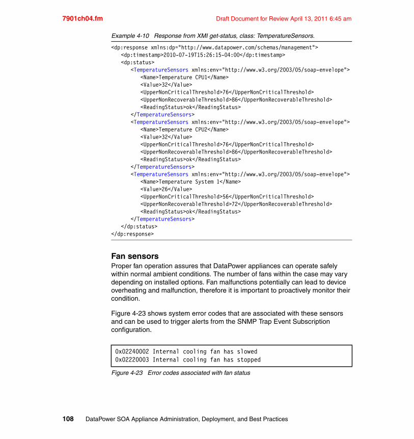
7901ch04.fm Draft Document for Review April 13, 2011 6:45 am
Example 4-10 Response from XMI get-status, class: TemperatureSensors.
<dp:response xmlns:dp="http://www.datapower.com/schemas/management"><dp:timestamp>2010-07-19T15:26:15-04:00</dp:timestamp><dp:status>
<TemperatureSensors xmlns:env="http://www.w3.org/2003/05/soap-envelope"><Name>Temperature CPU1</Name><Value>32</Value><UpperNonCriticalThreshold>76</UpperNonCriticalThreshold><UpperNonRecoverableThreshold>86</UpperNonRecoverableThreshold><ReadingStatus>ok</ReadingStatus>
</TemperatureSensors><TemperatureSensors xmlns:env="http://www.w3.org/2003/05/soap-envelope">
<Name>Temperature CPU2</Name><Value>32</Value><UpperNonCriticalThreshold>76</UpperNonCriticalThreshold><UpperNonRecoverableThreshold>86</UpperNonRecoverableThreshold><ReadingStatus>ok</ReadingStatus>
</TemperatureSensors><TemperatureSensors xmlns:env="http://www.w3.org/2003/05/soap-envelope">
<Name>Temperature System 1</Name><Value>26</Value><UpperNonCriticalThreshold>56</UpperNonCriticalThreshold><UpperNonRecoverableThreshold>72</UpperNonRecoverableThreshold><ReadingStatus>ok</ReadingStatus>
</TemperatureSensors></dp:status>
</dp:response>
Fan sensorsProper fan operation assures that DataPower appliances can operate safely within normal ambient conditions. The number of fans within the case may vary depending on installed options. Fan malfunctions potentially can lead to device overheating and malfunction, therefore it is important to proactively monitor their condition.
Figure 4-23 shows system error codes that are associated with these sensors and can be used to trigger alerts from the SNMP Trap Event Subscription configuration.
Figure 4-23 Error codes associated with fan status
0x02240002 Internal cooling fan has slowed0x02220003 Internal cooling fan has stopped
108 DataPower SOA Appliance Administration, Deployment, and Best Practices
Draft Document for Review April 13, 2011 6:45 am 7901ch04.fm
Table 4-11 shows the various ways for obtaining temperature sensor metrics. Figure 4-24 shows temperature sensor status as displayed in the WebGUI, and Example 4-11 shows the SOAP response from the XMI request for EnvironmentalFanSensors.
Table 4-11 Obtaining Fan Sensor Information
Figure 4-24 Fan sensor status as shown in the WebGUI.
Access Method Menu location, Command or Variable
WebGUI Status System Fan Sensors
CLI show sensors-fan
XMI Status Class EnvironmentalFanSensors
Status MIB dpStatusEnvironmentalFanSensorsTable
Chapter 4. SNMP monitoring 109
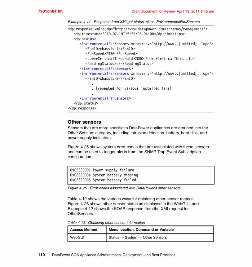
7901ch04.fm Draft Document for Review April 13, 2011 6:45 am
Example 4-11 Response from XMI get-status, class: EnvironmentalFanSensors.
<dp:response xmlns:dp="http://www.datapower.com/schemas/management"><dp:timestamp>2010-07-19T15:39:03-04:00</dp:timestamp><dp:status>
<EnvironmentalFanSensors xmlns:env="http://www..[omitted]..lope"><FanID>chassis-1</FanID><FanSpeed>7336</FanSpeed><LowerCriticalThreshold>2000</LowerCriticalThreshold><ReadingStatus>ok</ReadingStatus>
</EnvironmentalFanSensors><EnvironmentalFanSensors xmlns:env="http://www..[omitted]..lope">
<FanID>chassis-2</FanID>.. [repeated for various installed fans].
/EnvironmentalFanSensors></dp:status>
</dp:response>
Other sensorsSensors that are more specific to DataPower appliances are grouped into the Other Sensors category, including intrusion detection, battery, hard disk, and power supply indicators.
Figure 4-25 shows system error codes that are associated with these sensors and can be used to trigger alerts from the SNMP Trap Event Subscription configuration.
Figure 4-25 Error codes associated with DataPower’s other sensors
Table 4-12 shows the various ways for obtaining other sensor metrics. Figure 4-26 shows other sensor status as displayed in the WebGUI, and Example 4-12 shows the SOAP response from the XMI request for OtherSensors.
Table 4-12 Obtaining other sensor information
0x02220001 Power supply failure0x02220004 System battery missing0x02220005 System battery failed
Access Method Menu location, Command or Variable
WebGUI Status System Other Sensors
110 DataPower SOA Appliance Administration, Deployment, and Best Practices
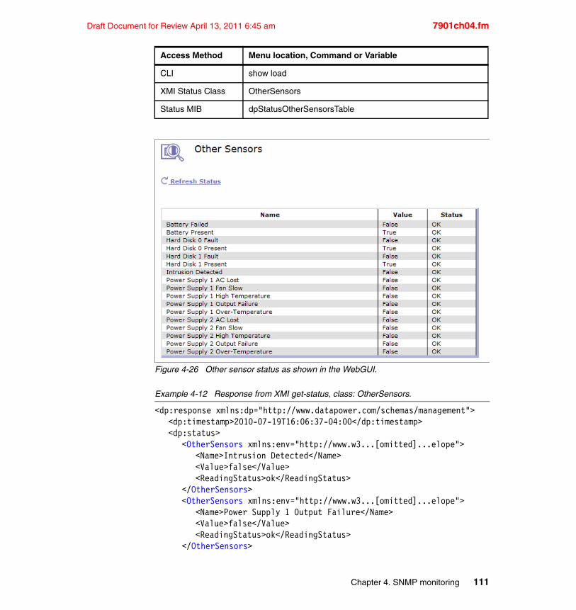
Draft Document for Review April 13, 2011 6:45 am 7901ch04.fm
Figure 4-26 Other sensor status as shown in the WebGUI.
Example 4-12 Response from XMI get-status, class: OtherSensors.
<dp:response xmlns:dp="http://www.datapower.com/schemas/management"><dp:timestamp>2010-07-19T16:06:37-04:00</dp:timestamp><dp:status>
<OtherSensors xmlns:env="http://www.w3...[omitted]...elope"><Name>Intrusion Detected</Name><Value>false</Value><ReadingStatus>ok</ReadingStatus>
</OtherSensors><OtherSensors xmlns:env="http://www.w3...[omitted]...elope">
<Name>Power Supply 1 Output Failure</Name><Value>false</Value><ReadingStatus>ok</ReadingStatus>
</OtherSensors>
CLI show load
XMI Status Class OtherSensors
Status MIB dpStatusOtherSensorsTable
Access Method Menu location, Command or Variable
Chapter 4. SNMP monitoring 111
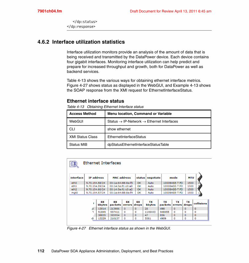
7901ch04.fm Draft Document for Review April 13, 2011 6:45 am
</dp:status></dp:response>
4.6.2 Interface utilization statistics
Interface utilization monitors provide an analysis of the amount of data that is being received and transmitted by the DataPower device. Each device contains four gigabit interfaces. Monitoring interface utilization can help predict and prepare for increased throughput and growth, both for DataPower as well as backend services.
Table 4-13 shows the various ways for obtaining ethernet interface metrics. Figure 4-27 shows status as displayed in the WebGUI, and Example 4-13 shows the SOAP response from the XMI request for EthernetInterfaceStatus.
Ethernet interface statusTable 4-13 Obtaining Ethernet Interface status
Figure 4-27 Ethernet interface status as shown in the WebGUI.
Access Method Menu location, Command or Variable
WebGUI Status IP-Network Ethernet Interfaces
CLI show ethernet
XMI Status Class EthernetInterfaceStatus
Status MIB dpStatusEthernetInterfaceStatusTable
112 DataPower SOA Appliance Administration, Deployment, and Best Practices
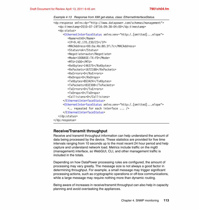
Draft Document for Review April 13, 2011 6:45 am 7901ch04.fm
Example 4-13 Response from XMI get-status, class: EthernetInterfaceStatus.
<dp:response xmlns:dp="http://www.datapower.com/schemas/management"><dp:timestamp>2010-07-19T16:09:38-04:00</dp:timestamp><dp:status>
<EthernetInterfaceStatus xmlns:env="http:/.[omitted]...elope"><Name>eth0</Name><IP>9.42.170.230/23</IP><MACAddress>00:0a:4b:80:3f:7c</MACAddress><Status>ok</Status><Negotiate>auto</Negotiate><Mode>100BASE-TX-FD</Mode><MTU>1500</MTU><RxKbytes>146375</RxKbytes><RxPackets>1672188</RxPackets><RxErrors>0</RxErrors><RxDrops>0</RxDrops><TxKbytes>853424</TxKbytes><TxPackets>832308</TxPackets><TxErrors>0</TxErrors><TxDrops>0</TxDrops><Collisions>0</Collisions>
</EthernetInterfaceStatus><EthernetInterfaceStatus xmlns:env="http:/.[omitted]...elope">
<.. repeated for each interface ... /></EthernetInterfaceStatus>
</dp:status></dp:response>
Receive/Transmit throughputReceive and transmit throughput information can help understand the amount of data being processed by the device. These statistics are provided for five time intervals ranging from 10 seconds up to the most recent 24 hour period and help capture and understand network load. Metrics include traffic on the mgt0 (management) interface, so WebGUI, CLI, and other management traffic is included in the totals.
Depending on how DataPower processing rules are configured, the amount of processing may vary greatly. The message size is not always a good factor in determining throughput. For example, a small message may trigger significant processing actions, such as cryptographic operations or off-box communications, while a large message may require nothing more than dynamic routing.
Being aware of increases in receive/transmit throughput can also help in capacity planning and avoid overtasking the appliances.
Chapter 4. SNMP monitoring 113
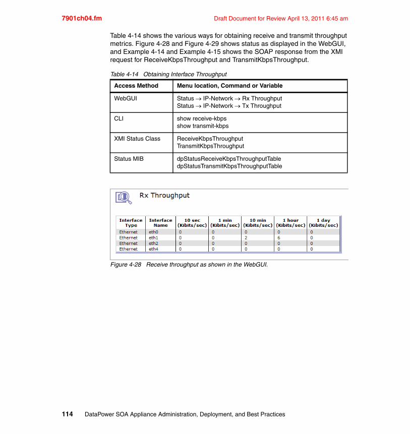
7901ch04.fm Draft Document for Review April 13, 2011 6:45 am
Table 4-14 shows the various ways for obtaining receive and transmit throughput metrics. Figure 4-28 and Figure 4-29 shows status as displayed in the WebGUI, and Example 4-14 and Example 4-15 shows the SOAP response from the XMI request for ReceiveKbpsThroughput and TransmitKbpsThroughput.
Table 4-14 Obtaining Interface Throughput
Figure 4-28 Receive throughput as shown in the WebGUI.
Access Method Menu location, Command or Variable
WebGUI Status IP-Network Rx ThroughputStatus IP-Network Tx Throughput
CLI show receive-kbpsshow transmit-kbps
XMI Status Class ReceiveKbpsThroughputTransmitKbpsThroughput
Status MIB dpStatusReceiveKbpsThroughputTabledpStatusTransmitKbpsThroughputTable
114 DataPower SOA Appliance Administration, Deployment, and Best Practices
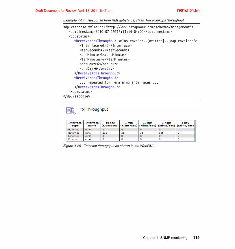
Draft Document for Review April 13, 2011 6:45 am 7901ch04.fm
Example 4-14 Response from XMI get-status, class: ReceiveKbpsThroughput.
<dp:response xmlns:dp="http://www.datapower.com/schemas/management"><dp:timestamp>2010-07-19T16:14:14-04:00</dp:timestamp><dp:status>
<ReceiveKbpsThroughput xmlns:env="ht..[omitted]...oap-envelope"><Interface>eth0</Interface><tenSeconds>2</tenSeconds><oneMinute>3</oneMinute><tenMinutes>7</tenMinutes><oneHour>6</oneHour><oneDay>6</oneDay>
</ReceiveKbpsThroughput><ReceiveKbpsThroughput>
... repeated for remaining interfaces ...</ReceiveKbpsThroughput>
</dp:status></dp:response>
Figure 4-29 Transmit throughput as shown in the WebGUI.
Chapter 4. SNMP monitoring 115
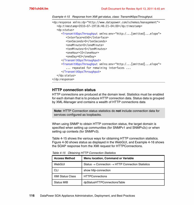
7901ch04.fm Draft Document for Review April 13, 2011 6:45 am
Example 4-15 Response from XMI get-status, class: TransmitKbpsThroughput.
<dp:response xmlns:dp="http://www.datapower.com/schemas/management"><dp:timestamp>2010-07-19T16:46:21-04:00</dp:timestamp><dp:status>
<TransmitKbpsThroughput xmlns:env="http:/...[omitted]...elope"><Interface>eth0</Interface><tenSeconds>0</tenSeconds><oneMinute>0</oneMinute><tenMinutes>5</tenMinutes><oneHour>33</oneHour><oneDay>63</oneDay>
</TransmitKbpsThroughput><TransmitKbpsThroughput xmlns:env="http:/...[omitted]...elope">
... repeated for remaining interfaces ...</TransmitKbpsThroughput>
</dp:status></dp:response>
HTTP connection statusHTTP connections are produced at the domain level. Statistics must be enabled for each domain that is to produce HTTP connection data. Status data is grouped by XML-Manager and contains a wealth of HTTP connections data
When using SNMP to obtain HTTP connection status, the target domain is specified when setting up communities (for SNMPv1 and SNMPv2c) or when setting up contexts (for SNMPv3).
Table 4-15 shows the various ways for obtaining HTTP connection statistics. Figure 4-30 shows status as displayed in the WebGUI, and Example 4-16 shows the SOAP response from the XMI request for HTTPConnections.
Table 4-15 Obtaining HTTP Connection Statistics
Note: HTTP Connection status statistics do not include connection data for services configured as loopbacks.
Access Method Menu location, Command or Variable
WebGUI Status Connection HTTP Connection Statistics
CLI show http-connection
XMI Status Class HTTPConnections
Status MIB dpStatusHTTPConnectionsTable
116 DataPower SOA Appliance Administration, Deployment, and Best Practices
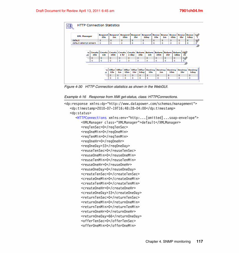
Draft Document for Review April 13, 2011 6:45 am 7901ch04.fm
Figure 4-30 HTTP Connection statistics as shown in the WebGUI.
Example 4-16 Response from XMI get-status, class: HTTPConnections.
<dp:response xmlns:dp="http://www.datapower.com/schemas/management"><dp:timestamp>2010-07-19T16:48:28-04:00</dp:timestamp><dp:status>
<HTTPConnections xmlns:env="http:...[omitted]...soap-envelope"><XMLManager class="XMLManager">default</XMLManager><reqTenSec>0</reqTenSec><reqOneMin>0</reqOneMin><reqTenMin>0</reqTenMin><reqOneHr>0</reqOneHr><reqOneDay>33</reqOneDay><reuseTenSec>0</reuseTenSec><reuseOneMin>0</reuseOneMin><reuseTenMin>0</reuseTenMin><reuseOneHr>0</reuseOneHr><reuseOneDay>0</reuseOneDay><createTenSec>0</createTenSec><createOneMin>0</createOneMin><createTenMin>0</createTenMin><createOneHr>0</createOneHr><createOneDay>33</createOneDay><returnTenSec>0</returnTenSec><returnOneMin>0</returnOneMin><returnTenMin>0</returnTenMin><returnOneHr>0</returnOneHr><returnOneDay>66</returnOneDay><offerTenSec>0</offerTenSec><offerOneMin>0</offerOneMin>
Chapter 4. SNMP monitoring 117
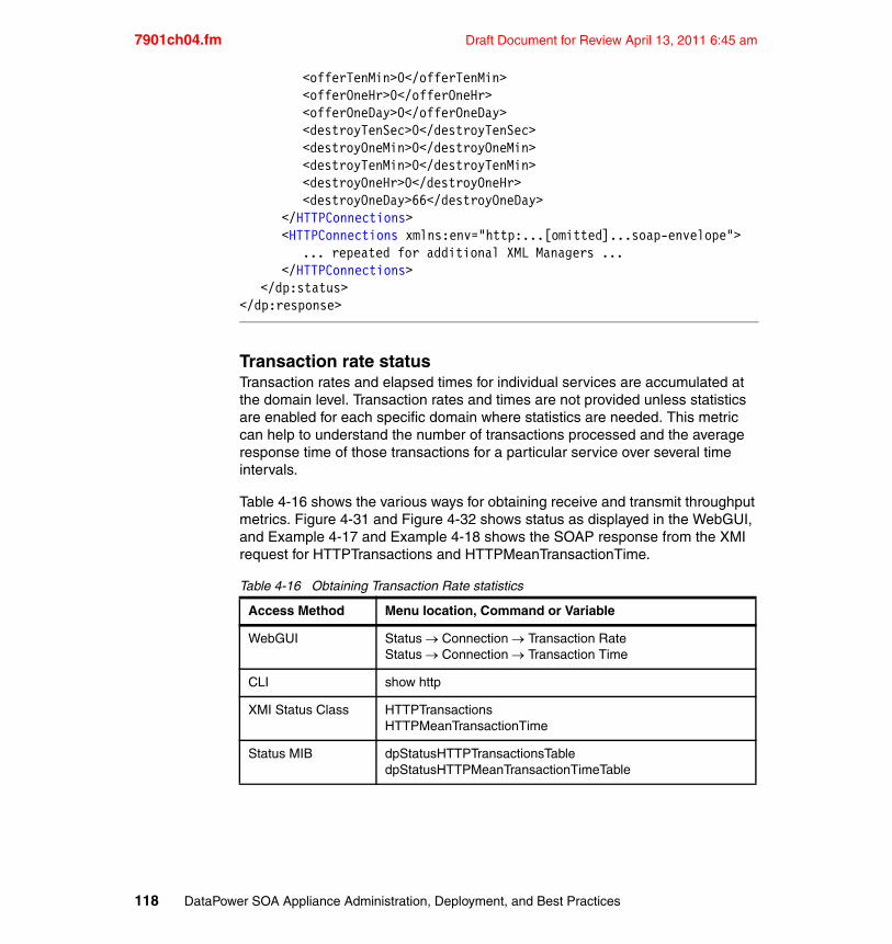
7901ch04.fm Draft Document for Review April 13, 2011 6:45 am
<offerTenMin>0</offerTenMin><offerOneHr>0</offerOneHr><offerOneDay>0</offerOneDay><destroyTenSec>0</destroyTenSec><destroyOneMin>0</destroyOneMin><destroyTenMin>0</destroyTenMin><destroyOneHr>0</destroyOneHr><destroyOneDay>66</destroyOneDay>
</HTTPConnections><HTTPConnections xmlns:env="http:...[omitted]...soap-envelope">
... repeated for additional XML Managers ...</HTTPConnections>
</dp:status></dp:response>
Transaction rate statusTransaction rates and elapsed times for individual services are accumulated at the domain level. Transaction rates and times are not provided unless statistics are enabled for each specific domain where statistics are needed. This metric can help to understand the number of transactions processed and the average response time of those transactions for a particular service over several time intervals.
Table 4-16 shows the various ways for obtaining receive and transmit throughput metrics. Figure 4-31 and Figure 4-32 shows status as displayed in the WebGUI, and Example 4-17 and Example 4-18 shows the SOAP response from the XMI request for HTTPTransactions and HTTPMeanTransactionTime.
Table 4-16 Obtaining Transaction Rate statistics
Access Method Menu location, Command or Variable
WebGUI Status Connection Transaction RateStatus Connection Transaction Time
CLI show http
XMI Status Class HTTPTransactionsHTTPMeanTransactionTime
Status MIB dpStatusHTTPTransactionsTabledpStatusHTTPMeanTransactionTimeTable
118 DataPower SOA Appliance Administration, Deployment, and Best Practices
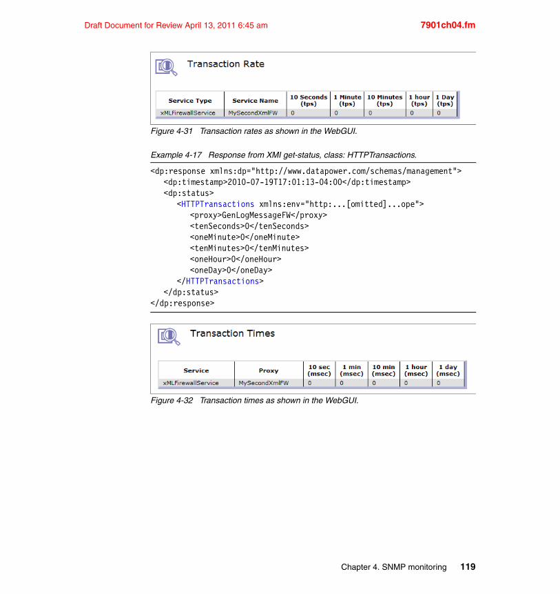
Draft Document for Review April 13, 2011 6:45 am 7901ch04.fm
Figure 4-31 Transaction rates as shown in the WebGUI.
Example 4-17 Response from XMI get-status, class: HTTPTransactions.
<dp:response xmlns:dp="http://www.datapower.com/schemas/management"><dp:timestamp>2010-07-19T17:01:13-04:00</dp:timestamp><dp:status>
<HTTPTransactions xmlns:env="http:...[omitted]...ope"><proxy>GenLogMessageFW</proxy><tenSeconds>0</tenSeconds><oneMinute>0</oneMinute><tenMinutes>0</tenMinutes><oneHour>0</oneHour><oneDay>0</oneDay>
</HTTPTransactions></dp:status>
</dp:response>
Figure 4-32 Transaction times as shown in the WebGUI.
Chapter 4. SNMP monitoring 119
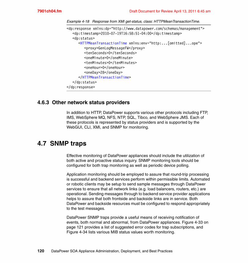
7901ch04.fm Draft Document for Review April 13, 2011 6:45 am
Example 4-18 Response from XMI get-status, class: HTTPMeanTransactionTime.
<dp:response xmlns:dp="http://www.datapower.com/schemas/management"><dp:timestamp>2010-07-19T16:58:51-04:00</dp:timestamp><dp:status>
<HTTPMeanTransactionTime xmlns:env="http:...[omitted]...ope"><proxy>GenLogMessageFW</proxy><tenSeconds>0</tenSeconds><oneMinute>0</oneMinute><tenMinutes>0</tenMinutes><oneHour>0</oneHour><oneDay>28</oneDay>
</HTTPMeanTransactionTime></dp:status>
</dp:response>
4.6.3 Other network status providers
In addition to HTTP, DataPower supports various other protocols including FTP, IMS, WebSphere MQ, NFS, NTP, SQL, Tibco, and WebSphere JMS. Each of these protocols is represented by status providers and is supported by the WebGUI, CLI, XMI, and SNMP for monitoring.
4.7 SNMP traps
Effective monitoring of DataPower appliances should include the utilization of both active and proactive status inquiry. SNMP monitoring tools should be configured for both trap monitoring as well as periodic device polling.
Application monitoring should be employed to assure that round-trip processing is successful and backend services perform within permissible limits. Automated or robotic clients may be setup to send sample messages through DataPower services to ensure that all network links (e.g. load balancers, routers, etc.) are operational. Sending messages through to backend service provider applications helps to assure that both frontside and backside links are in service. Both DataPower and backside resources must be configured to respond appropriately to the test messages.
DataPower SNMP traps provide a useful means of receiving notification of events, both normal and abnormal, from DataPower appliances. Figure 4-33 on page 121 provides a list of suggested error codes for trap subscriptions, and Figure 4-34 lists various MIB status values worth monitoring.
120 DataPower SOA Appliance Administration, Deployment, and Best Practices
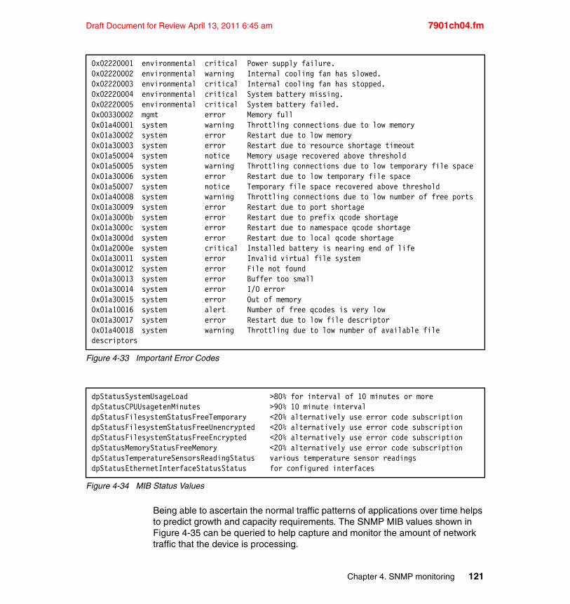
Draft Document for Review April 13, 2011 6:45 am 7901ch04.fm
Figure 4-33 Important Error Codes
Figure 4-34 MIB Status Values
Being able to ascertain the normal traffic patterns of applications over time helps to predict growth and capacity requirements. The SNMP MIB values shown in Figure 4-35 can be queried to help capture and monitor the amount of network traffic that the device is processing.
0x02220001 environmental critical Power supply failure.0x02220002 environmental warning Internal cooling fan has slowed.0x02220003 environmental critical Internal cooling fan has stopped.0x02220004 environmental critical System battery missing.0x02220005 environmental critical System battery failed.0x00330002 mgmt error Memory full0x01a40001 system warning Throttling connections due to low memory0x01a30002 system error Restart due to low memory0x01a30003 system error Restart due to resource shortage timeout0x01a50004 system notice Memory usage recovered above threshold0x01a50005 system warning Throttling connections due to low temporary file space0x01a30006 system error Restart due to low temporary file space0x01a50007 system notice Temporary file space recovered above threshold0x01a40008 system warning Throttling connections due to low number of free ports0x01a30009 system error Restart due to port shortage0x01a3000b system error Restart due to prefix qcode shortage0x01a3000c system error Restart due to namespace qcode shortage0x01a3000d system error Restart due to local qcode shortage0x01a2000e system critical Installed battery is nearing end of life0x01a30011 system error Invalid virtual file system0x01a30012 system error File not found0x01a30013 system error Buffer too small0x01a30014 system error I/O error0x01a30015 system error Out of memory0x01a10016 system alert Number of free qcodes is very low0x01a30017 system error Restart due to low file descriptor0x01a40018 system warning Throttling due to low number of available file descriptors
dpStatusSystemUsageLoad >80% for interval of 10 minutes or moredpStatusCPUUsagetenMinutes >90% 10 minute intervaldpStatusFilesystemStatusFreeTemporary <20% alternatively use error code subscriptiondpStatusFilesystemStatusFreeUnencrypted <20% alternatively use error code subscriptiondpStatusFilesystemStatusFreeEncrypted <20% alternatively use error code subscriptiondpStatusMemoryStatusFreeMemory <20% alternatively use error code subscriptiondpStatusTemperatureSensorsReadingStatus various temperature sensor readingsdpStatusEthernetInterfaceStatusStatus for configured interfaces
Chapter 4. SNMP monitoring 121
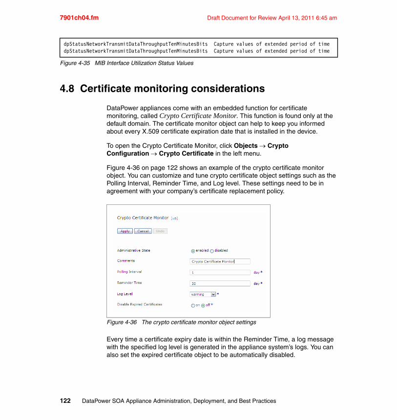
7901ch04.fm Draft Document for Review April 13, 2011 6:45 am
Figure 4-35 MIB Interface Utilization Status Values
4.8 Certificate monitoring considerations
DataPower appliances come with an embedded function for certificate monitoring, called Crypto Certificate Monitor. This function is found only at the default domain. The certificate monitor object can help to keep you informed about every X.509 certificate expiration date that is installed in the device.
To open the Crypto Certificate Monitor, click Objects Crypto Configuration Crypto Certificate in the left menu.
Figure 4-36 on page 122 shows an example of the crypto certificate monitor object. You can customize and tune crypto certificate object settings such as the Polling Interval, Reminder Time, and Log level. These settings need to be in agreement with your company’s certificate replacement policy.
Figure 4-36 The crypto certificate monitor object settings
Every time a certificate expiry date is within the Reminder Time, a log message with the specified log level is generated in the appliance system’s logs. You can also set the expired certificate object to be automatically disabled.
dpStatusNetworkTransmitDataThroughputTenMinutesBits Capture values of extended period of timedpStatusNetworkTransmitDataThroughputTenMinutesBits Capture values of extended period of time
122 DataPower SOA Appliance Administration, Deployment, and Best Practices
Draft Document for Review April 13, 2011 6:45 am 7901ch04.fm
For better results and visibility regarding certificates expiry, always enable the crypto certificate monitor functionality. The device administrator needs to make sure this step is included on every initial setup process.
Set a log target with the cert-monitor categoryA log target can capture log messages that are generated by the objects and services that are set on a DataPower appliance. The main feature within a log target is the target type option. A target type allows the appliance to deal with log messages and files, such as using encryption and signing, and it can also send the messages to remote servers.
During a log target setup, you must set up an event category subscription. A log category is used to relate log events and messages under a same subject. Thus, a category determines the subjects in which a log target is interested. A log target receives only messages that are related to its subscribed categories. DataPower appliances come with some log categories set and enabled by default. A useful category for certificate monitoring is the cert-monitor category. You can use this category when setting monitoring for certificates expiry.
A good monitoring option for certificates is to combine an event category, such as the cert-monitor, with a remote target type option. This way, certificates expiry related messages can be sent remotely using one of the various options available such as SMTP, NFS, SOAP, and syslog (or syslog-ng).
Ensure monitoring traps are setInformation regarding certificates expiry are generated when the crypto certificate monitor object is enabled and when a log target is set. The problem is that information can be useless if no one is watching for it. The best monitoring suites available offer the ability to set an alert or an alarm trap. Such traps can be set in order to call for attention.
An example would be to have the device administrator group emailed every time a certificate expired log entry is found. Alternatively, the production support team can be paged, or perhaps both situations can occur. The monitoring response can vary depending on your company support process.
It is essential that anyone who works with monitoring traps have a deep knowledge of the monitoring suite that is used. Alerts and alarms are generally not enabled by default. They need to be enabled and set based on your company criterion. For best results when monitoring certificates, set alarms and traps.
Important: Keep in mind that any other crypto objects that reference the disabled certificate object will also be disabled.
Chapter 4. SNMP monitoring 123
7901ch04.fm Draft Document for Review April 13, 2011 6:45 am
Define a certificate replacement policyMost companies do business with several partners. Thus, a DataPower appliance can have certificates from several companies installed on it. Because certificates are critical documents, a company must have a well-defined certificate replacement policy.
Remember that your partners have their own policy for dealing with certificates. Some partners can take more time to deploy a new certificate than others. Also, certificates need to be signed by a certificate authority (CA). Each CA has their own service level agreement (SLA), which can also cause a delay.
4.9 Best practices and considerations
� Use both subscription-based alerts as well as device polling for the most robust monitoring strategy. Reliance on alerts alone is not a sufficient monitoring strategy. The device may become unable to transmit alerts.
� Host Aliases should be defined (in the default domain) and used instead of actual IP address when identifying SNMP managers
� Use a Host Alias when specifying the IP address for the XML Management Interface, especially in production environments. Leaving the IP address as 0.0.0.0 allows requests to be received on any IP address defined on the appliance. Generally speaking, the management interface is used for XMI traffic (mgt0 or eth4)
� Since SNMP community strings are essentially passwords that allow access to the SNMP agent, community strings should adhere to the same creation rules (mixed case, must contain a number, etc.) as regular passwords
� Unless it is necessary for the SNMP manager to set values from MIB-II and other IETF MIBs, it is recommended that all communities defined on DataPower be read-only. There are no read-write values defined within the DataPower MIBs
� Host Aliases should be defined (in the default domain) and used instead of actual IP address when identifying SNMP managers
� Unless application/domain specific data is required, associate SNMP communities with the default domain
124 DataPower SOA Appliance Administration, Deployment, and Best Practices
Draft Document for Review April 13, 2011 6:45 am 7901ch05.fm
Chapter 5. IBM Tivoli Monitoring
IBM Tivoli Monitoring is a collection of components that provide a means to manage distributed resources through centralized control and configuration. Tivoli Monitoring is used as the foundation for a set of products that are built on top of Tivoli Monitoring, such as IBM Tivoli Composite Application Manager (ITCAM) and Omegamon family of products. These Tivoli Monitoring-based products can help you manage the performance and availability of distributed operating systems, applications, and DataPower appliances. Tivoli Monitoring seamless integrates these products that alert, identify, and isolate an incident with the subject matter expert tools that diagnose and resolve the problem.
This chapter introduces the various Tivoli components and how they work together with DataPower appliances.
5
© Copyright IBM Corp. 2011. All rights reserved. 125
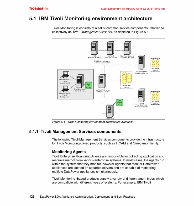
7901ch05.fm Draft Document for Review April 13, 2011 6:45 am
5.1 IBM Tivoli Monitoring environment architecture
Tivoli Monitoring is consists of a set of common service components, referred to collectively as Tivoli Management Services, as depicted in Figure 5-1.
Figure 5-1 Tivoli Monitoring environment architecture overview
5.1.1 Tivoli Management Services components
The following Tivoli Management Services components provide the infrastructure for Tivoli Monitoring-based products, such as ITCAM and Omegamon family.
Monitoring AgentsTivoli Enterprise Monitoring Agents are responsible for collecting application and resource metrics from various enterprise systems. In most cases, the agents run within the system that they monitor, however agents that monitor DataPower appliances are located on separate servers and are capable of monitoring multiple DataPower appliances simultaneously.
Tivoli Monitoring -based products supply a variety of different agent types which are compatible with different types of systems. For example, IBM Tivoli
IBMNetcoo l/OMNIbus
IBM Tivoli BusinessSystems Manager
Monitoringagents
Tivoli Data
RemoteTivoli Enterprise
Monitoring Server
RemoteTivoli Enterprise
Monitoring Server
Tivoli EnterprisePortal
browser client
Tivoli EnterprisePortal
desktop client
Tivol i EnterprisePor tal Server
XXX XXXX XXXXXXXX XX
DB2or
MSSQL
DB2,MSSQL,
orOracle
Monitor ingagents
Monitor ingagents
IBM Tivol iEnterprise Console
Tivo li Event Integrationevent synchronization
Hub Tivoli EnterpriseMonitoring Server
XXX XXXX XXXXXXXX XX
126 DataPower SOA Appliance Administration, Deployment, and Best Practices
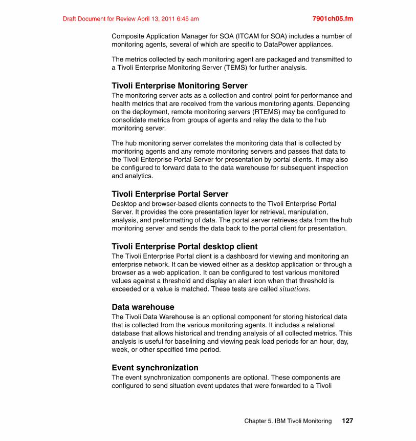
Draft Document for Review April 13, 2011 6:45 am 7901ch05.fm
Composite Application Manager for SOA (ITCAM for SOA) includes a number of monitoring agents, several of which are specific to DataPower appliances.
The metrics collected by each monitoring agent are packaged and transmitted to a Tivoli Enterprise Monitoring Server (TEMS) for further analysis.
Tivoli Enterprise Monitoring ServerThe monitoring server acts as a collection and control point for performance and health metrics that are received from the various monitoring agents. Depending on the deployment, remote monitoring servers (RTEMS) may be configured to consolidate metrics from groups of agents and relay the data to the hub monitoring server.
The hub monitoring server correlates the monitoring data that is collected by monitoring agents and any remote monitoring servers and passes that data to the Tivoli Enterprise Portal Server for presentation by portal clients. It may also be configured to forward data to the data warehouse for subsequent inspection and analytics.
Tivoli Enterprise Portal ServerDesktop and browser-based clients connects to the Tivoli Enterprise Portal Server. It provides the core presentation layer for retrieval, manipulation, analysis, and preformatting of data. The portal server retrieves data from the hub monitoring server and sends the data back to the portal client for presentation.
Tivoli Enterprise Portal desktop clientThe Tivoli Enterprise Portal client is a dashboard for viewing and monitoring an enterprise network. It can be viewed either as a desktop application or through a browser as a web application. It can be configured to test various monitored values against a threshold and display an alert icon when that threshold is exceeded or a value is matched. These tests are called situations.
Data warehouseThe Tivoli Data Warehouse is an optional component for storing historical data that is collected from the various monitoring agents. It includes a relational database that allows historical and trending analysis of all collected metrics. This analysis is useful for baselining and viewing peak load periods for an hour, day, week, or other specified time period.
Event synchronizationThe event synchronization components are optional. These components are configured to send situation event updates that were forwarded to a Tivoli
Chapter 5. IBM Tivoli Monitoring 127
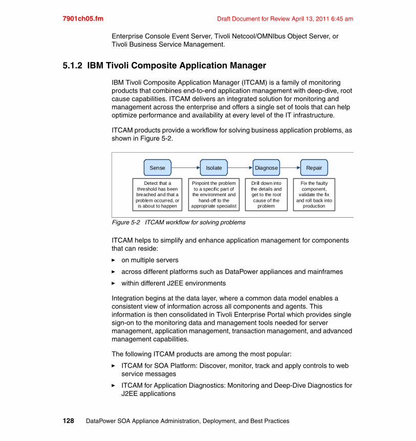
7901ch05.fm Draft Document for Review April 13, 2011 6:45 am
Enterprise Console Event Server, Tivoli Netcool/OMNIbus Object Server, or Tivoli Business Service Management.
5.1.2 IBM Tivoli Composite Application Manager
IBM Tivoli Composite Application Manager (ITCAM) is a family of monitoring products that combines end-to-end application management with deep-dive, root cause capabilities. ITCAM delivers an integrated solution for monitoring and management across the enterprise and offers a single set of tools that can help optimize performance and availability at every level of the IT infrastructure.
ITCAM products provide a workflow for solving business application problems, as shown in Figure 5-2.
Figure 5-2 ITCAM workflow for solving problems
ITCAM helps to simplify and enhance application management for components that can reside:
� on multiple servers
� across different platforms such as DataPower appliances and mainframes
� within different J2EE environments
Integration begins at the data layer, where a common data model enables a consistent view of information across all components and agents. This information is then consolidated in Tivoli Enterprise Portal which provides single sign-on to the monitoring data and management tools needed for server management, application management, transaction management, and advanced management capabilities.
The following ITCAM products are among the most popular:
� ITCAM for SOA Platform: Discover, monitor, track and apply controls to web service messages
� ITCAM for Application Diagnostics: Monitoring and Deep-Dive Diagnostics for J2EE applications
Detect that a threshold has been breached and that a problem occurred, or is about to happen
Sense Isolate
Pinpoint the problem to a specific part of
the environment and hand-off to the
appropriate specialist
Diagnose
Drill down into the details and get to the root cause of the
problem
Repair
Fix the faulty component,
validate the fix and roll back into
production
128 DataPower SOA Appliance Administration, Deployment, and Best Practices
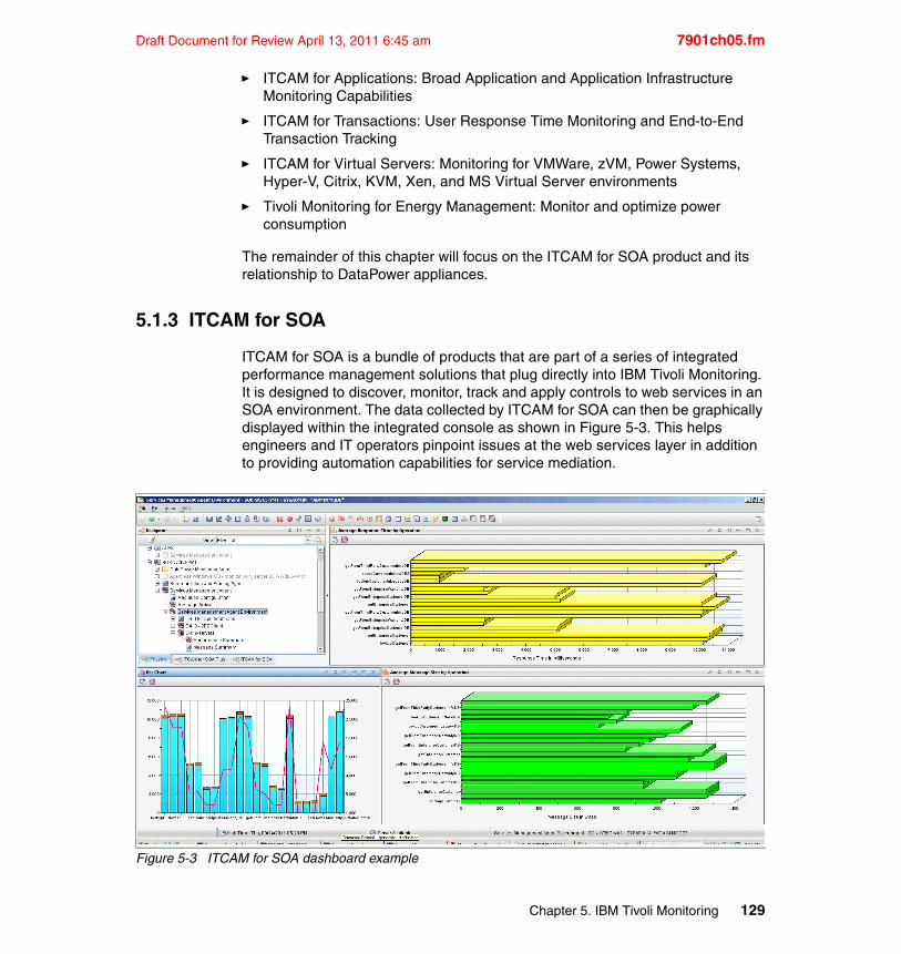
Draft Document for Review April 13, 2011 6:45 am 7901ch05.fm
� ITCAM for Applications: Broad Application and Application Infrastructure Monitoring Capabilities
� ITCAM for Transactions: User Response Time Monitoring and End-to-End Transaction Tracking
� ITCAM for Virtual Servers: Monitoring for VMWare, zVM, Power Systems, Hyper-V, Citrix, KVM, Xen, and MS Virtual Server environments
� Tivoli Monitoring for Energy Management: Monitor and optimize power consumption
The remainder of this chapter will focus on the ITCAM for SOA product and its relationship to DataPower appliances.
5.1.3 ITCAM for SOA
ITCAM for SOA is a bundle of products that are part of a series of integrated performance management solutions that plug directly into IBM Tivoli Monitoring. It is designed to discover, monitor, track and apply controls to web services in an SOA environment. The data collected by ITCAM for SOA can then be graphically displayed within the integrated console as shown in Figure 5-3. This helps engineers and IT operators pinpoint issues at the web services layer in addition to providing automation capabilities for service mediation.
Figure 5-3 ITCAM for SOA dashboard example
Chapter 5. IBM Tivoli Monitoring 129
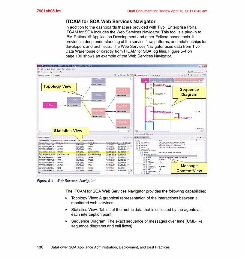
7901ch05.fm Draft Document for Review April 13, 2011 6:45 am
ITCAM for SOA Web Services NavigatorIn addition to the dashboards that are provided with Tivoli Enterprise Portal, ITCAM for SOA includes the Web Services Navigator. This tool is a plug-in to IBM Rational® Application Development and other Eclipse-based tools. It provides a deep understanding of the service flow, patterns, and relationships for developers and architects. The Web Services Navigator uses data from Tivoli Data Warehouse or directly from ITCAM for SOA log files. Figure 5-4 on page 130 shows an example of the Web Services Navigator.
Figure 5-4 Web Services Navigator
The ITCAM for SOA Web Services Navigator provides the following capabilities:
� Topology View: A graphical representation of the interactions between all monitored web services
� Statistics View: Tables of the metric data that is collected by the agents at each interception point
� Sequence Diagram: The exact sequence of messages over time (UML-like sequence diagrams and call flows)
130 DataPower SOA Appliance Administration, Deployment, and Best Practices
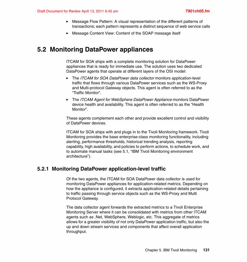
Draft Document for Review April 13, 2011 6:45 am 7901ch05.fm
� Message Flow Pattern: A visual representation of the different patterns of transactions; each pattern represents a distinct sequence of web service calls
� Message Content View: Content of the SOAP message itself
5.2 Monitoring DataPower appliances
ITCAM for SOA ships with a complete monitoring solution for DataPower appliances that is ready for immediate use. The solution uses two dedicated DataPower agents that operate at different layers of the OSI model:
� The ITCAM for SOA DataPower data collector monitors application-level traffic that flows through various DataPower services such as the WS-Proxy and Multi-protocol Gateway objects. This agent is often referred to as the “Traffic Monitor”.
� The ITCAM Agent for WebSphere DataPower Appliance monitors DataPower device health and availability. This agent is often referred to as the “Health Monitor”.
These agents complement each other and provide excellent control and visibility of DataPower devices.
ITCAM for SOA ships with and plugs in to the Tivoli Monitoring framework. Tivoli Monitoring provides the base enterprise-class monitoring functionality, including alerting, performance thresholds, historical trending analysis, reporting capability, high availability, and policies to perform actions, to schedule work, and to automate manual tasks (see 5.1, “IBM Tivoli Monitoring environment architecture”).
5.2.1 Monitoring DataPower application-level traffic
Of the two agents, the ITCAM for SOA DataPower data collector is used for monitoring DataPower appliances for application-related metrics. Depending on how the appliance is configured, it extracts application-related details pertaining to traffic passing through service objects such as the WS-Proxy and Multi Protocol Gateway.
The data collector agent forwards the extracted metrics to a Tivoli Enterprise Monitoring Server where it can be consolidated with metrics from other ITCAM agents such as .Net, WebSphere, Weblogic, etc. This aggregate of metrics allows for a greater visibility of not only DataPower application traffic, but also the up and down stream services and components that affect overall application throughput.
Chapter 5. IBM Tivoli Monitoring 131
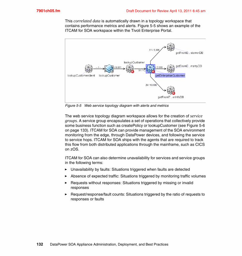
7901ch05.fm Draft Document for Review April 13, 2011 6:45 am
This correlated data is automatically drawn in a topology workspace that contains performance metrics and alerts. Figure 5-5 shows an example of the ITCAM for SOA workspace within the Tivoli Enterprise Portal.
Figure 5-5 Web service topology diagram with alerts and metrics
The web service topology diagram workspace allows for the creation of service groups. A service group encapsulates a set of operations that collectively provide some business function such as createPolicy or lookupCustomer (see Figure 5-6 on page 133). ITCAM for SOA can provide management of the SOA environment monitoring from the edge, through DataPower devices, and following the service to service hops. ITCAM for SOA ships with the agents that are required to track this flow from both distributed applications through the mainframe, such as CICS on zOS.
ITCAM for SOA can also determine unavailability for services and service groups in the following terms:
� Unavailability by faults: Situations triggered when faults are detected
� Absence of expected traffic: Situations triggered by monitoring traffic volumes
� Requests without responses: Situations triggered by missing or invalid responses
� Request/response/fault counts: Situations triggered by the ratio of requests to responses or faults
132 DataPower SOA Appliance Administration, Deployment, and Best Practices
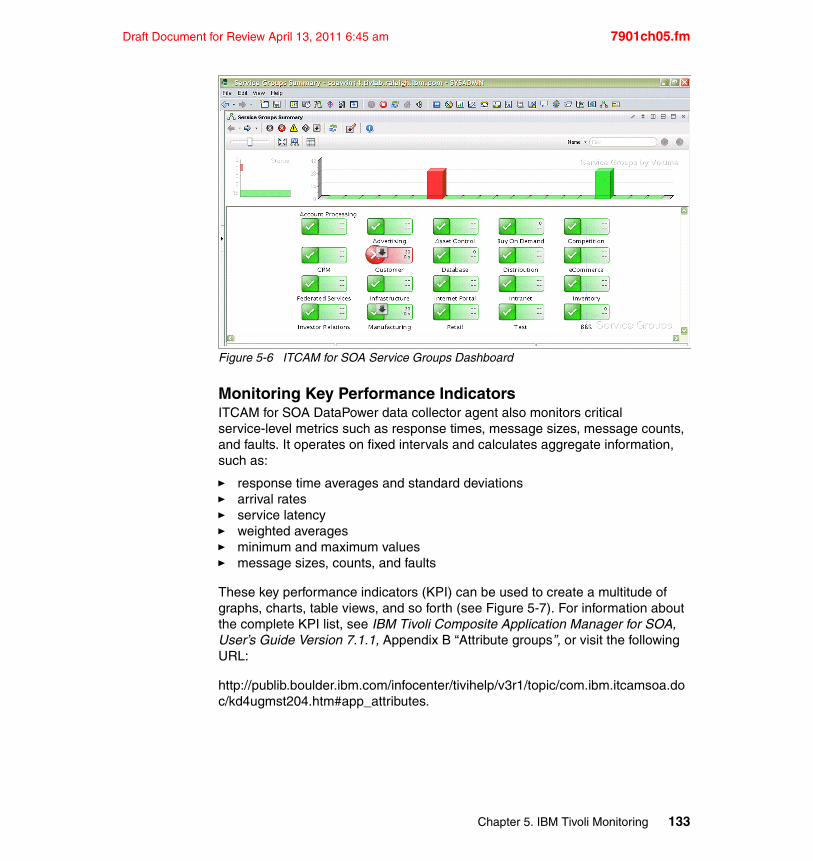
Draft Document for Review April 13, 2011 6:45 am 7901ch05.fm
Figure 5-6 ITCAM for SOA Service Groups Dashboard
Monitoring Key Performance IndicatorsITCAM for SOA DataPower data collector agent also monitors critical service-level metrics such as response times, message sizes, message counts, and faults. It operates on fixed intervals and calculates aggregate information, such as:
� response time averages and standard deviations� arrival rates� service latency� weighted averages� minimum and maximum values� message sizes, counts, and faults
These key performance indicators (KPI) can be used to create a multitude of graphs, charts, table views, and so forth (see Figure 5-7). For information about the complete KPI list, see IBM Tivoli Composite Application Manager for SOA, User’s Guide Version 7.1.1, Appendix B “Attribute groups”, or visit the following URL:
http://publib.boulder.ibm.com/infocenter/tivihelp/v3r1/topic/com.ibm.itcamsoa.doc/kd4ugmst204.htm#app_attributes.
Chapter 5. IBM Tivoli Monitoring 133
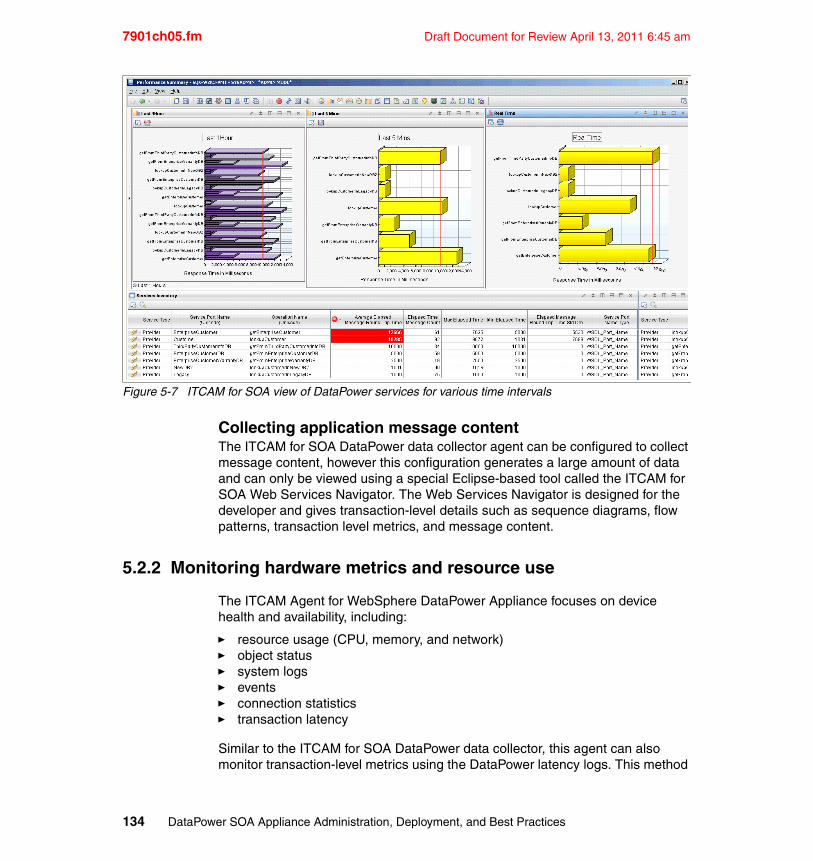
7901ch05.fm Draft Document for Review April 13, 2011 6:45 am
Figure 5-7 ITCAM for SOA view of DataPower services for various time intervals
Collecting application message contentThe ITCAM for SOA DataPower data collector agent can be configured to collect message content, however this configuration generates a large amount of data and can only be viewed using a special Eclipse-based tool called the ITCAM for SOA Web Services Navigator. The Web Services Navigator is designed for the developer and gives transaction-level details such as sequence diagrams, flow patterns, transaction level metrics, and message content.
5.2.2 Monitoring hardware metrics and resource use
The ITCAM Agent for WebSphere DataPower Appliance focuses on device health and availability, including:
� resource usage (CPU, memory, and network)� object status� system logs� events� connection statistics� transaction latency
Similar to the ITCAM for SOA DataPower data collector, this agent can also monitor transaction-level metrics using the DataPower latency logs. This method
134 DataPower SOA Appliance Administration, Deployment, and Best Practices
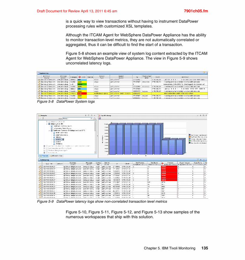
Draft Document for Review April 13, 2011 6:45 am 7901ch05.fm
is a quick way to view transactions without having to instrument DataPower processing rules with customized XSL templates.
Although the ITCAM Agent for WebSphere DataPower Appliance has the ability to monitor transaction-level metrics, they are not automatically correlated or aggregated, thus it can be difficult to find the start of a transaction.
Figure 5-8 shows an example view of system log content extracted by the ITCAM Agent for WebSphere DataPower Appliance. The view in Figure 5-9 shows uncorrelated latency logs.
Figure 5-8 DataPower System logs
Figure 5-9 DataPower latency logs show non-correlated transaction level metrics
Figure 5-10, Figure 5-11, Figure 5-12, and Figure 5-13 show samples of the numerous workspaces that ship with this solution.
Chapter 5. IBM Tivoli Monitoring 135
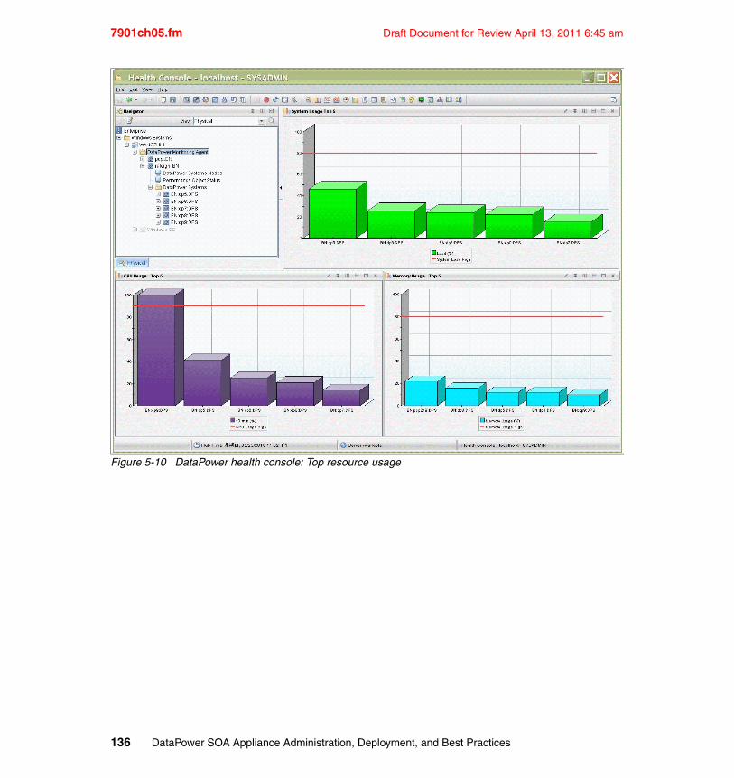
7901ch05.fm Draft Document for Review April 13, 2011 6:45 am
Figure 5-10 DataPower health console: Top resource usage
136 DataPower SOA Appliance Administration, Deployment, and Best Practices
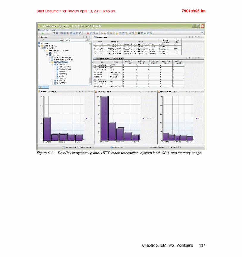
Draft Document for Review April 13, 2011 6:45 am 7901ch05.fm
Figure 5-11 DataPower system uptime, HTTP mean transaction, system load, CPU, and memory usage
Chapter 5. IBM Tivoli Monitoring 137
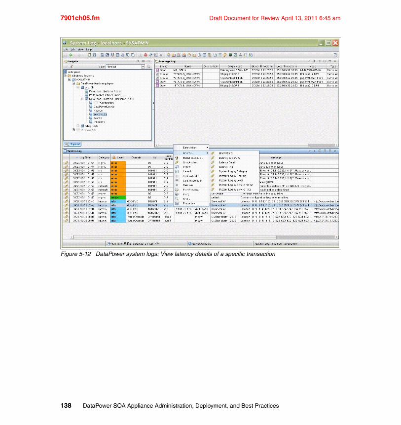
7901ch05.fm Draft Document for Review April 13, 2011 6:45 am
Figure 5-12 DataPower system logs: View latency details of a specific transaction
138 DataPower SOA Appliance Administration, Deployment, and Best Practices
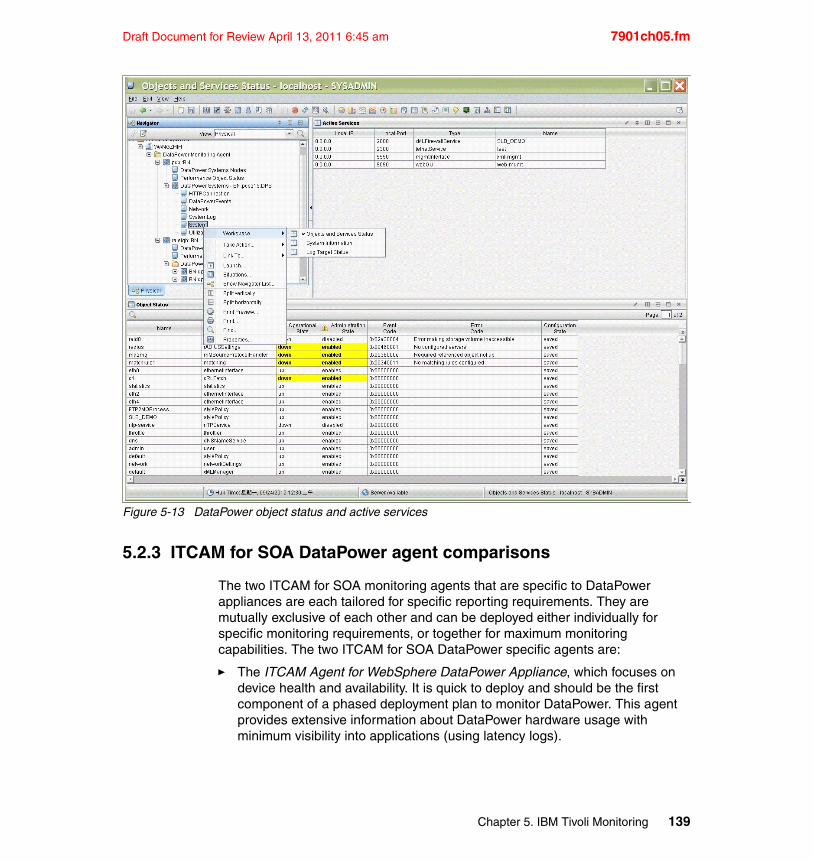
Draft Document for Review April 13, 2011 6:45 am 7901ch05.fm
Figure 5-13 DataPower object status and active services
5.2.3 ITCAM for SOA DataPower agent comparisons
The two ITCAM for SOA monitoring agents that are specific to DataPower appliances are each tailored for specific reporting requirements. They are mutually exclusive of each other and can be deployed either individually for specific monitoring requirements, or together for maximum monitoring capabilities. The two ITCAM for SOA DataPower specific agents are:
� The ITCAM Agent for WebSphere DataPower Appliance, which focuses on device health and availability. It is quick to deploy and should be the first component of a phased deployment plan to monitor DataPower. This agent provides extensive information about DataPower hardware usage with minimum visibility into applications (using latency logs).
Chapter 5. IBM Tivoli Monitoring 139
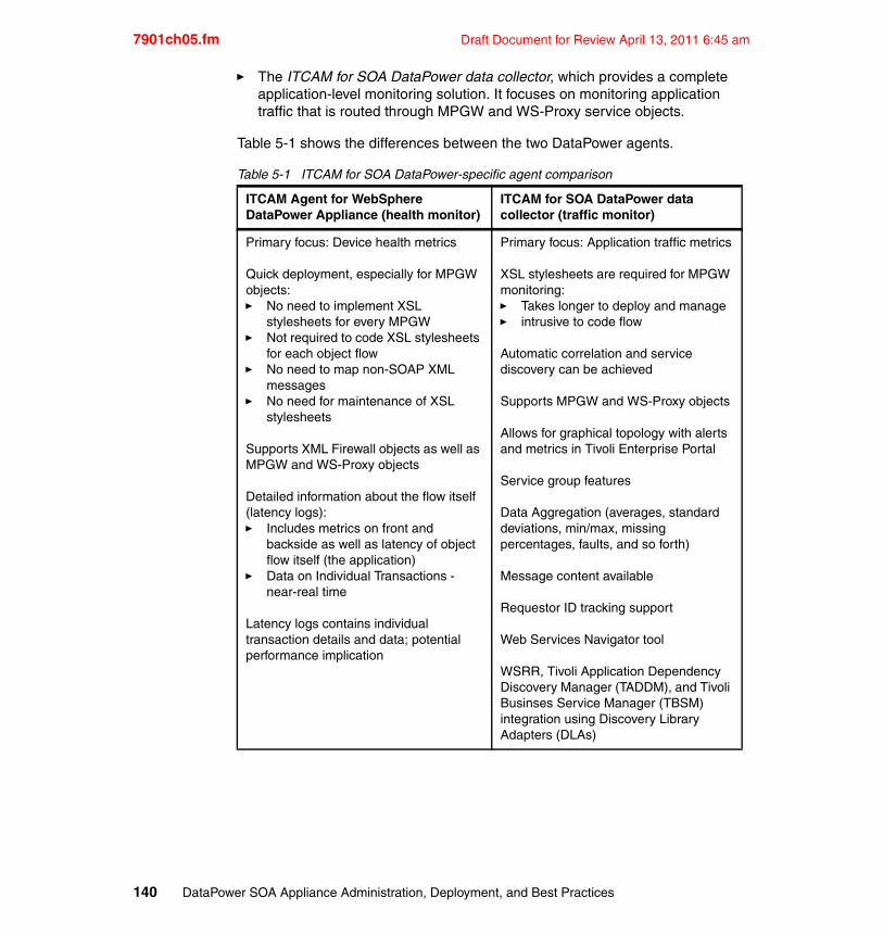
7901ch05.fm Draft Document for Review April 13, 2011 6:45 am
� The ITCAM for SOA DataPower data collector, which provides a complete application-level monitoring solution. It focuses on monitoring application traffic that is routed through MPGW and WS-Proxy service objects.
Table 5-1 shows the differences between the two DataPower agents.
Table 5-1 ITCAM for SOA DataPower-specific agent comparison
ITCAM Agent for WebSphere DataPower Appliance (health monitor)
ITCAM for SOA DataPower data collector (traffic monitor)
Primary focus: Device health metrics
Quick deployment, especially for MPGW objects:� No need to implement XSL
stylesheets for every MPGW� Not required to code XSL stylesheets
for each object flow� No need to map non-SOAP XML
messages � No need for maintenance of XSL
stylesheets
Supports XML Firewall objects as well as MPGW and WS-Proxy objects
Detailed information about the flow itself (latency logs):� Includes metrics on front and
backside as well as latency of object flow itself (the application)
� Data on Individual Transactions - near-real time
Latency logs contains individual transaction details and data; potential performance implication
Primary focus: Application traffic metrics
XSL stylesheets are required for MPGW monitoring:� Takes longer to deploy and manage� intrusive to code flow
Automatic correlation and service discovery can be achieved
Supports MPGW and WS-Proxy objects
Allows for graphical topology with alerts and metrics in Tivoli Enterprise Portal
Service group features
Data Aggregation (averages, standard deviations, min/max, missing percentages, faults, and so forth)
Message content available
Requestor ID tracking support
Web Services Navigator tool
WSRR, Tivoli Application Dependency Discovery Manager (TADDM), and Tivoli Businses Service Manager (TBSM) integration using Discovery Library Adapters (DLAs)
140 DataPower SOA Appliance Administration, Deployment, and Best Practices
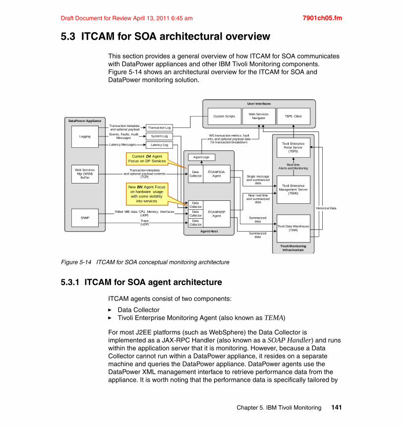
Draft Document for Review April 13, 2011 6:45 am 7901ch05.fm
5.3 ITCAM for SOA architectural overview
This section provides a general overview of how ITCAM for SOA communicates with DataPower appliances and other IBM Tivoli Monitoring components. Figure 5-14 shows an architectural overview for the ITCAM for SOA and DataPower monitoring solution.
Figure 5-14 ITCAM for SOA conceptual monitoring architecture
5.3.1 ITCAM for SOA agent architecture
ITCAM agents consist of two components:
� Data Collector� Tivoli Enterprise Monitoring Agent (also known as TEMA)
For most J2EE platforms (such as WebSphere) the Data Collector is implemented as a JAX-RPC Handler (also known as a SOAP Handler) and runs within the application server that it is monitoring. However, because a Data Collector cannot run within a DataPower appliance, it resides on a separate machine and queries the DataPower appliance. DataPower agents use the DataPower XML management interface to retrieve performance data from the appliance. It is worth noting that the performance data is specifically tailored by
Tivoli MonitoringInfrastructure
Agent Host
DataPower Appliance
User Interfaces
Transaction Log
Web ServicesMgt (WSM)
Buffer
Agent Logs
Custom Scripts TEPS Client
Tivoli EnterprisePortal Server
(TEPS)
Single messageand summarized
data
Near real-timeand summarized
data
Summarizeddata
Summarizeddata
WS transaction metrics, faultinfo, and optional payload data
for transaction breakdown
DataCollector
Polled MIB data: CPU, Memory, Interfaces (UDP)
Traps(UDP)
DataCollector
DataCollector
DataCollector
Latency Messages
Transaction metadata and optional payload
Events, Faults, Audit MessagesLogging
SNMP
Transaction metadataand optional payload contents
(TCP)
Historical Data
Web ServicesNavigator
Real-timeAlerts and Monitoring
Tivoli Data Warehouse(TDW)
ITCAMfWDPAgent
ITCAMfSOAAgent
Tivoli EnterpriseManagement Server
(TEMS)
System Log
Latency Log
New BN Agent Focuson hardware usagewith some visibility
into services
Current D4 AgentFocus on DP Services
Chapter 5. IBM Tivoli Monitoring 141
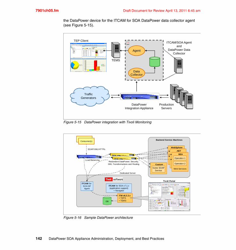
7901ch05.fm Draft Document for Review April 13, 2011 6:45 am
the DataPower device for the ITCAM for SOA DataPower data collector agent (see Figure 5-15).
Figure 5-15 DataPower integration with Tivoli Monitoring
Figure 5-16 Sample DataPower architecture
TEP Client
TEMS
ITCAM/SOA Agentand
DataPower DataCollector
ProductionServers
DataPowerIntegration Appliance
DataCollector
Agent
TrafficGenerators
Backend Service MachinesConsumer(s)
ITCAM for SOA v7.1.x(application support)
+ Navigator
SOAP/XML/HTTPs
Load BalancingRedundant DataPower; Security,
XML Transformations and Routing
Dedicated Server
Tivoli Portal
DB
Custom
Some SOAPService
Consumer(s)
ITCAM for SOA DP
Agent
ITM v6.2.2.x• TEPS• TEMS
WebSphere
.NET
BEA
Operation 1
Operation 2
Web Services
142 DataPower SOA Appliance Administration, Deployment, and Best Practices
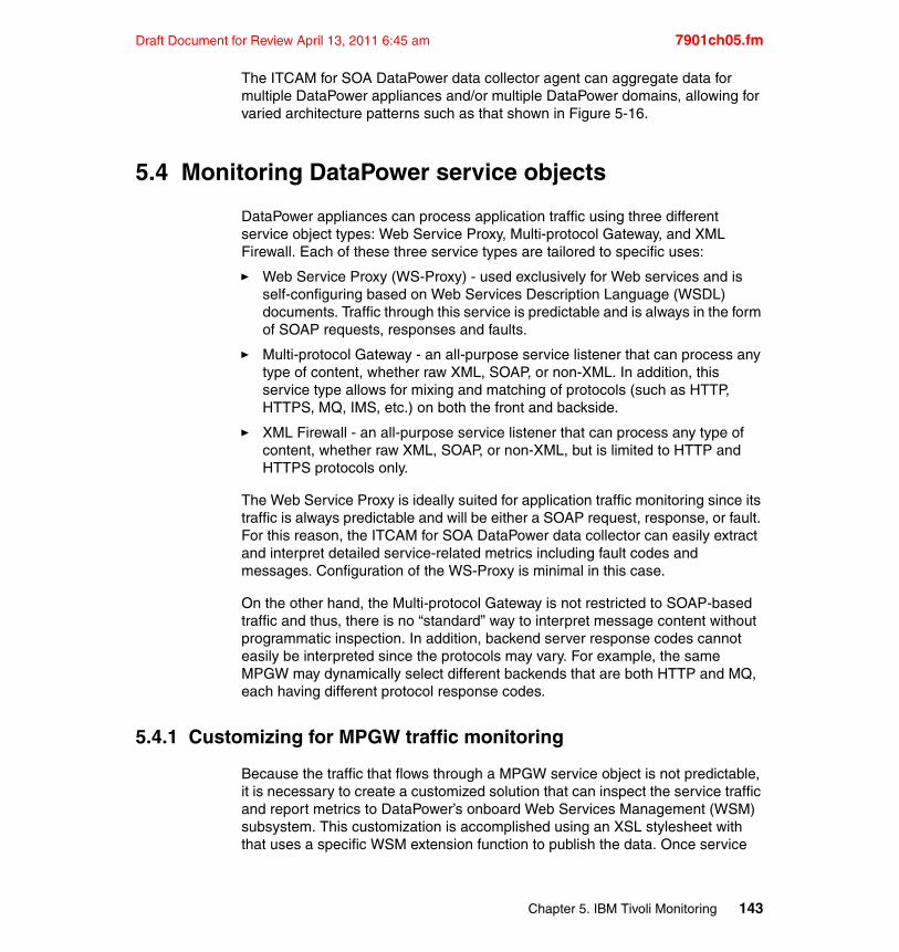
Draft Document for Review April 13, 2011 6:45 am 7901ch05.fm
The ITCAM for SOA DataPower data collector agent can aggregate data for multiple DataPower appliances and/or multiple DataPower domains, allowing for varied architecture patterns such as that shown in Figure 5-16.
5.4 Monitoring DataPower service objects
DataPower appliances can process application traffic using three different service object types: Web Service Proxy, Multi-protocol Gateway, and XML Firewall. Each of these three service types are tailored to specific uses:
� Web Service Proxy (WS-Proxy) - used exclusively for Web services and is self-configuring based on Web Services Description Language (WSDL) documents. Traffic through this service is predictable and is always in the form of SOAP requests, responses and faults.
� Multi-protocol Gateway - an all-purpose service listener that can process any type of content, whether raw XML, SOAP, or non-XML. In addition, this service type allows for mixing and matching of protocols (such as HTTP, HTTPS, MQ, IMS, etc.) on both the front and backside.
� XML Firewall - an all-purpose service listener that can process any type of content, whether raw XML, SOAP, or non-XML, but is limited to HTTP and HTTPS protocols only.
The Web Service Proxy is ideally suited for application traffic monitoring since its traffic is always predictable and will be either a SOAP request, response, or fault. For this reason, the ITCAM for SOA DataPower data collector can easily extract and interpret detailed service-related metrics including fault codes and messages. Configuration of the WS-Proxy is minimal in this case.
On the other hand, the Multi-protocol Gateway is not restricted to SOAP-based traffic and thus, there is no “standard” way to interpret message content without programmatic inspection. In addition, backend server response codes cannot easily be interpreted since the protocols may vary. For example, the same MPGW may dynamically select different backends that are both HTTP and MQ, each having different protocol response codes.
5.4.1 Customizing for MPGW traffic monitoring
Because the traffic that flows through a MPGW service object is not predictable, it is necessary to create a customized solution that can inspect the service traffic and report metrics to DataPower’s onboard Web Services Management (WSM) subsystem. This customization is accomplished using an XSL stylesheet with that uses a specific WSM extension function to publish the data. Once service
Chapter 5. IBM Tivoli Monitoring 143
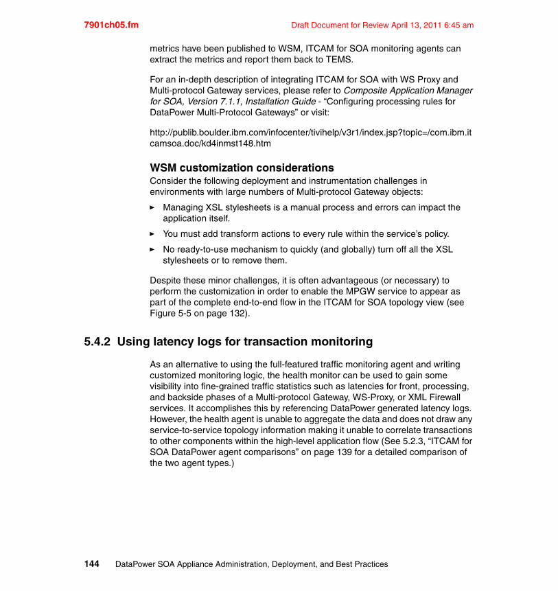
7901ch05.fm Draft Document for Review April 13, 2011 6:45 am
metrics have been published to WSM, ITCAM for SOA monitoring agents can extract the metrics and report them back to TEMS.
For an in-depth description of integrating ITCAM for SOA with WS Proxy and Multi-protocol Gateway services, please refer to Composite Application Manager for SOA, Version 7.1.1, Installation Guide - “Configuring processing rules for DataPower Multi-Protocol Gateways” or visit:
http://publib.boulder.ibm.com/infocenter/tivihelp/v3r1/index.jsp?topic=/com.ibm.itcamsoa.doc/kd4inmst148.htm
WSM customization considerationsConsider the following deployment and instrumentation challenges in environments with large numbers of Multi-protocol Gateway objects:
� Managing XSL stylesheets is a manual process and errors can impact the application itself.
� You must add transform actions to every rule within the service’s policy.
� No ready-to-use mechanism to quickly (and globally) turn off all the XSL stylesheets or to remove them.
Despite these minor challenges, it is often advantageous (or necessary) to perform the customization in order to enable the MPGW service to appear as part of the complete end-to-end flow in the ITCAM for SOA topology view (see Figure 5-5 on page 132).
5.4.2 Using latency logs for transaction monitoring
As an alternative to using the full-featured traffic monitoring agent and writing customized monitoring logic, the health monitor can be used to gain some visibility into fine-grained traffic statistics such as latencies for front, processing, and backside phases of a Multi-protocol Gateway, WS-Proxy, or XML Firewall services. It accomplishes this by referencing DataPower generated latency logs. However, the health agent is unable to aggregate the data and does not draw any service-to-service topology information making it unable to correlate transactions to other components within the high-level application flow (See 5.2.3, “ITCAM for SOA DataPower agent comparisons” on page 139 for a detailed comparison of the two agent types.)
144 DataPower SOA Appliance Administration, Deployment, and Best Practices
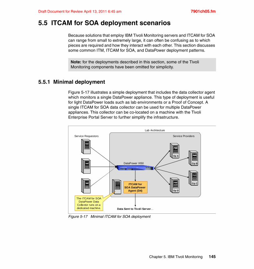
Draft Document for Review April 13, 2011 6:45 am 7901ch05.fm
5.5 ITCAM for SOA deployment scenarios
Because solutions that employ IBM Tivoli Monitoring servers and ITCAM for SOA can range from small to extremely large, it can often be confusing as to which pieces are required and how they interact with each other. This section discusses some common ITM, ITCAM for SOA, and DataPower deployment patterns.
5.5.1 Minimal deployment
Figure 5-17 illustrates a simple deployment that includes the data collector agent which monitors a single DataPower appliance. This type of deployment is useful for light DataPower loads such as lab environments or a Proof of Concept. A single ITCAM for SOA data collector can be used for multiple DataPower appliances. This collector can be co-located on a machine with the Tivoli Enterprise Portal Server to further simplify the infrastructure.
Figure 5-17 Minimal ITCAM for SOA deployment
Note: for the deployments described in this section, some of the Tivoli Monitoring components have been omitted for simplicity.
Lab Architecture
ITCAM forSOA DataPower
Agent (D4)
DataPower XI50
Service Requestors
Data Sent to Tivoli Server…
Service Providers
Op A
Op B
Op C
Op D
The ITCAM for SOA DataPower Data
Collector runs on a dedicated machine.
Chapter 5. IBM Tivoli Monitoring 145
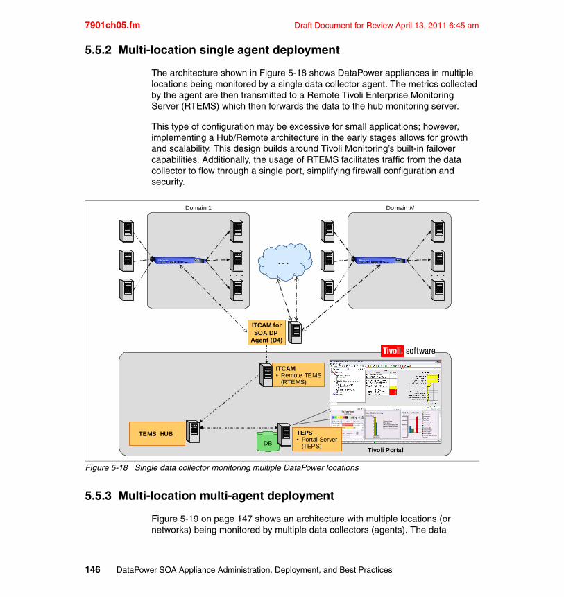
7901ch05.fm Draft Document for Review April 13, 2011 6:45 am
5.5.2 Multi-location single agent deployment
The architecture shown in Figure 5-18 shows DataPower appliances in multiple locations being monitored by a single data collector agent. The metrics collected by the agent are then transmitted to a Remote Tivoli Enterprise Monitoring Server (RTEMS) which then forwards the data to the hub monitoring server.
This type of configuration may be excessive for small applications; however, implementing a Hub/Remote architecture in the early stages allows for growth and scalability. This design builds around Tivoli Monitoring’s built-in failover capabilities. Additionally, the usage of RTEMS facilitates traffic from the data collector to flow through a single port, simplifying firewall configuration and security.
Figure 5-18 Single data collector monitoring multiple DataPower locations
5.5.3 Multi-location multi-agent deployment
Figure 5-19 on page 147 shows an architecture with multiple locations (or networks) being monitored by multiple data collectors (agents). The data
Tivoli Portal
TEMS HUB
ITCAM • Remote TEMS
(RTEMS)
Domain 1
. . .
ITCAM forSOA DP
Agent (D4)
. . .
Domain N
. . .
DB
TEPS• Portal Server
(TEPS)
146 DataPower SOA Appliance Administration, Deployment, and Best Practices
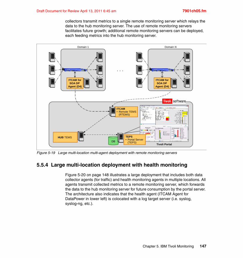
Draft Document for Review April 13, 2011 6:45 am 7901ch05.fm
collectors transmit metrics to a single remote monitoring server which relays the data to the hub monitoring server. The use of remote monitoring servers facilitates future growth; additional remote monitoring servers can be deployed, each feeding metrics into the hub monitoring server.
Figure 5-19 Large multi-location multi-agent deployment with remote monitoring servers
5.5.4 Large multi-location deployment with health monitoring
Figure 5-20 on page 148 illustrates a large deployment that includes both data collector agents (for traffic) and health monitoring agents in multiple locations. All agents transmit collected metrics to a remote monitoring server, which forwards the data to the hub monitoring server for future consumption by the portal server. The architecture also indicates that the health agent (ITCAM Agent for DataPower in lower left) is colocated with a log target server (i.e. syslog, syslog-ng, etc.).
Tivoli Portal
HUB TEMS
ITCAM • Remote TEMS
(RTEMS)
Domain 1
. . .
Domain N
. . .
DB
. . .
ITCAM forSOA DP
Agent (D4)
ITCAM forSOA DP
Agent (D4)
TEPS• Portal Server
(TEPS)
Chapter 5. IBM Tivoli Monitoring 147
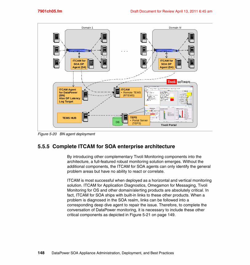
7901ch05.fm Draft Document for Review April 13, 2011 6:45 am
Figure 5-20 BN agent deployment
5.5.5 Complete ITCAM for SOA enterprise architecture
By introducing other complementary Tivoli Monitoring components into the architecture, a full-featured robust monitoring solution emerges. Without the additional components, the ITCAM for SOA agents can only identify the general problem areas but have no ability to react or correlate.
ITCAM is most successful when deployed as a horizontal and vertical monitoring solution. ITCAM for Application Diagnostics, Omegamon for Messaging, Tivoli Monitoring for OS and other domain/alerting products are absolutely critical. In fact, ITCAM for SOA ships with built-in links to these other products. When a problem is diagnosed in the SOA realm, links can be followed into a corresponding deep dive agent to repair the issue. Therefore, to complete the conversation of DataPower monitoring, it is necessary to include these other critical components as depicted in Figure 5-21 on page 149.
Tivoli Portal
TEMS HUB
ITCAM • Remote TEMS
(RTEMS)
Domain 1
. . .
Domain N
. . .
DB
. . .
ITCAM forSOA DP
Agent (D4)
ITCAM Agentfor DataPower(BN)Also DP LatencyLog Target
ITCAM forSOA DP
Agent (D4)
TEPS• Portal Server
(TEPS)
148 DataPower SOA Appliance Administration, Deployment, and Best Practices
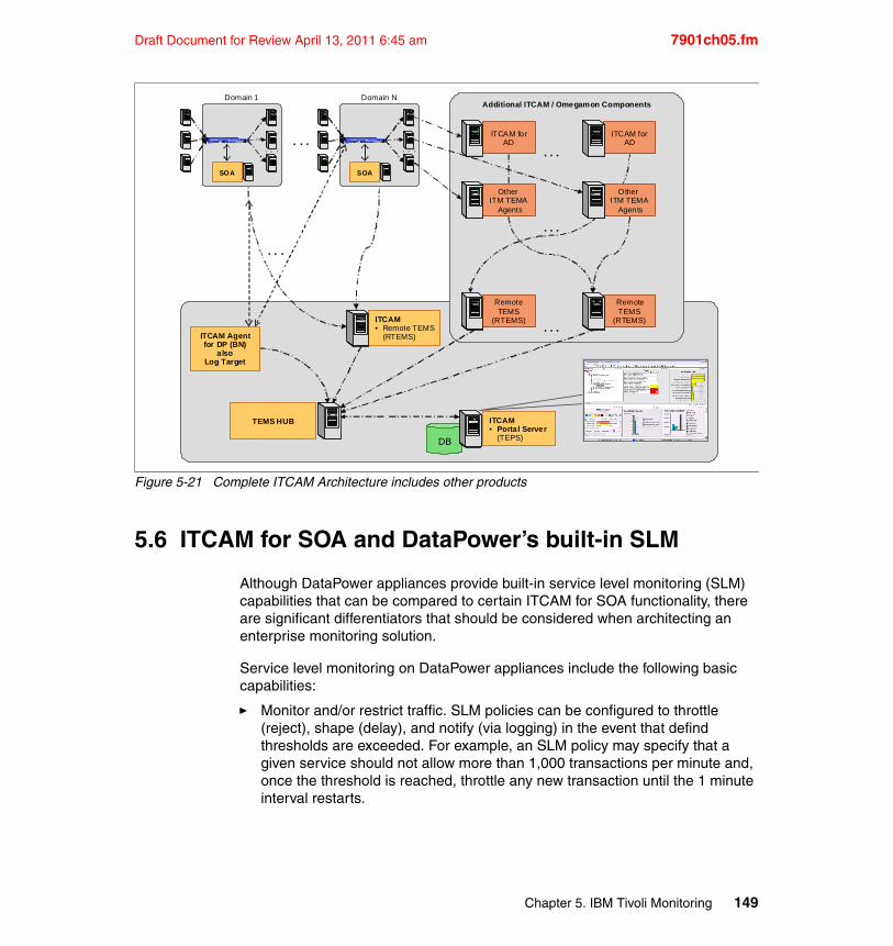
Draft Document for Review April 13, 2011 6:45 am 7901ch05.fm
Figure 5-21 Complete ITCAM Architecture includes other products
5.6 ITCAM for SOA and DataPower’s built-in SLM
Although DataPower appliances provide built-in service level monitoring (SLM) capabilities that can be compared to certain ITCAM for SOA functionality, there are significant differentiators that should be considered when architecting an enterprise monitoring solution.
Service level monitoring on DataPower appliances include the following basic capabilities:
� Monitor and/or restrict traffic. SLM policies can be configured to throttle (reject), shape (delay), and notify (via logging) in the event that defind thresholds are exceeded. For example, an SLM policy may specify that a given service should not allow more than 1,000 transactions per minute and, once the threshold is reached, throttle any new transaction until the 1 minute interval restarts.
. . .. . .
SOA
Domain N
TEMS HUB
ITCAM • Remote TEMS
(RTEMS)
ITCAM • Portal Server
(TEPS)
ITCAM Agentfor DP (BN)
alsoLog Target
DB
ITCAM forAD
ITCAM forAD
Other ITM TEMA
Agents
Remote TEMS
(RTEMS)
RemoteTEMS
(RTEMS)
. . .
. . .
. . .
. . .
. . .
SOA
Domain 1Additional ITCAM / Omegamon Components
Other ITM TEMA
Agents
Chapter 5. IBM Tivoli Monitoring 149
7901ch05.fm Draft Document for Review April 13, 2011 6:45 am
� SLM policies can contain simple rules as well as complex rules involving message inspection and XPath evaluation. For example, limit the number of times a service is called by a specific user for a specified SOAP operation.
� SLM policies can reference latency values, causing notifications to occur if backend processes exceed certain thresholds.
� Service level monitors can be applied across multiple DataPower devices, allowing installations to enforce SLM policies based on aggregated counts across peer devices.
� Basic graphing through the WebGUI. A simple graph can be displayed showing throttled, shaped, and notified transaction counts over a period of time.
In general, The DataPower SLM feature is excellent for ESB-like capabilities and individual DataPower appliance troubleshooting, but it was not intended to serve as an enterprise-wide, operations level monitoring solution. ITCAM for SOA provides the following capabilities above and beyond what DataPower’s built-in SLM can provide:
� Long-term storage of transaction metrics for subsequent analysis, historical graphing, reporting, and compliance.
� Easy cross-referencing of metrics and correlation to other environmental components.
� Impact analysis and “drill-down” for root cause analysis.
5.7 Deployment considerations
This chapter has provided a general overview of the IBM Tivoli Monitoring solution and ITCAM for SOA as they relate to DataPower appliances. Together these offerings provide a full-featured robust solution to manage and monitor the performance and availability of complex distributed topologies.
The remaining topics in this section address specific considerations that can help assure that a deployment functions both reliable and efficiently. These considerations focus primarily on agent deployment and DataPower configurations.
5.7.1 ITCAM for SOA DataPower data collector (traffic)
The following topics should be considered when configuring and deploying the ITCAM Agent for WebSphere DataPower Appliance:
150 DataPower SOA Appliance Administration, Deployment, and Best Practices
Draft Document for Review April 13, 2011 6:45 am 7901ch05.fm
5.7.2 ITCAM Agent for WebSphere DataPower Appliance (health)
The following topics should be considered when configuring and deploying the ITCAM Agent for WebSphere DataPower Appliance:
� For latency log monitoring, the latency log target should exist on the same machine as the agent that monitors it.
If it is not possible to co-locate the agent and the log target on the same machine, a file transfer mechanism such as FTP can be employed to copy the latency logs from the log target machine to the agent’s host machine.
5.7.3 DataPower appliance
Chapter 5. IBM Tivoli Monitoring 151

7901ch05.fm Draft Document for Review April 13, 2011 6:45 am
152 DataPower SOA Appliance Administration, Deployment, and Best Practices
Draft Document for Review April 13, 2011 6:45 am 7901ch06.fm
Chapter 6. Logging
Organizations of all types and sizes need to keep a record of activity within their enterprise computing systems, particularly when those systems interact directly with external customers. Only by keeping such records, or logs, can the organization find the cause of failures or unexpected results, or, in some cases, prove that any given transaction actually did occur. A robust logging system can also be used to continually monitor all enterprise systems, to ensure that each system is performing as expected and that corporate guidelines are followed. Similar to using a security camera in a brick-and-mortar store, logging does not prevent incidents from happening but can help to identify the root cause of an issue.
This chapter provides information that can help in planning a logging solution. Topics covered include the following:
� Overview of the DataPower logging systems
� Log types and destinations available
� Methods for event and transaction logging
� Privacy considerations
� Best practice recommendations
6
© Copyright IBM Corp. 2011. All rights reserved. 153
7901ch06.fm Draft Document for Review April 13, 2011 6:45 am
6.1 Overview
The device offers two distinct types of logging:
� Message process logging
These logs capture log messages generated as the device processes messages flowing through the device. The device can generate two kinds of processing messages: event-driven messages and transactional messages.
� Audit logging
Audit logs capture messages generated by changes to the configuration of the device, or by administrators logging into the device.
The Audit logs and the Message process logs are distinct, and require different handling procedures.
6.1.1 Message process logging
The device can generate two different kinds of logs during message processing:
� Event logging
The device generates log messages automatically during operation. Every subsystem within the device can and will generate log messages as events occur within those systems. These messages can be very verbose (at a debug level) or very sparse (at a warning or critical level). Administrators can set the depth and frequency of event-driven log messages. See 6.4, “Event logging” on page 158 for more information.
� Transaction logging
Transaction logging enables the capture of messages flowing through the device during processing. Transaction logging employs either a Log Action or a Results Action within the processing policy of the service, allowing access to the contents of messages flowing through the device. The messages logged can be much larger than the standard logging system allows. The standard event logging system is not used at all. See 6.5, “Transaction logging” on page 160 for more information about transactional logging.
6.1.2 Publish and subscribe system
The event logging system works as a publish and subscribe system. Each of the subsystems, or objects, within the device generate, or publish, log messages. Log targets capture, or subscribe to one or more published logging streams. The default system log subscribes to all logging streams. It is possible to create a
154 DataPower SOA Appliance Administration, Deployment, and Best Practices
Draft Document for Review April 13, 2011 6:45 am 7901ch06.fm
wide range of log targets that subscribe to any subset of published streams, enabling administrators to capture only the information desired.
6.1.3 Log targets and log categories
Each log message generated belongs to a particular log category, or type. Log targets can subscribe to a selection of categories. In addition to the standard categories of messages generated, the logging system also offers the ability to create custom log categories, allowing for the capture of completely custom messages.
The containers, or objects, that subscribe to published log messages are called log targets. Administrators can create any number of log targets, each subscribed to different categories of log messages or of error events. It is possible to create log targets that are highly focussed and thus provide rapid access to only the log messages or other events of interest. It is also possible to create log targets that capture a wide range of messages, providing a general context for processing events within the device.
6.1.4 Storing log messages
Log targets offer a number of methods for storing messages and for moving stored messages off the device to other repositories for analysis. The methods for storing log messages fall into two basic categories: writing to a cache or file, or dispatching messages in real time to external servers.
Writing to local file or cacheThe log target system can write to a file on the local file system. These archive files are necessarily limited in size to eliminate the possibility of filing up the local storage system. The system can support rotating files so that messages are not lost when the file size limit is reached. Once full, the rotated file can then be moved off of the device to another storage system for permanent keeping and analysis. Methods for automatically moving log files off the device include FTP, SMTP and HTTP, to name a few. It is also possible to write to files that are NFS drives, pointing to files that are stored on remote servers.
If the device offers hard drive storage, the hard drives can be used for log storage. Even when using the hard drives, log archive files need to be moved off of the device at regular intervals.
Writing to a remote serverThe log target system can dispatch log messages immediately to remote servers, thus moving all storage off of the device. These servers can include syslog,
Chapter 6. Logging 155
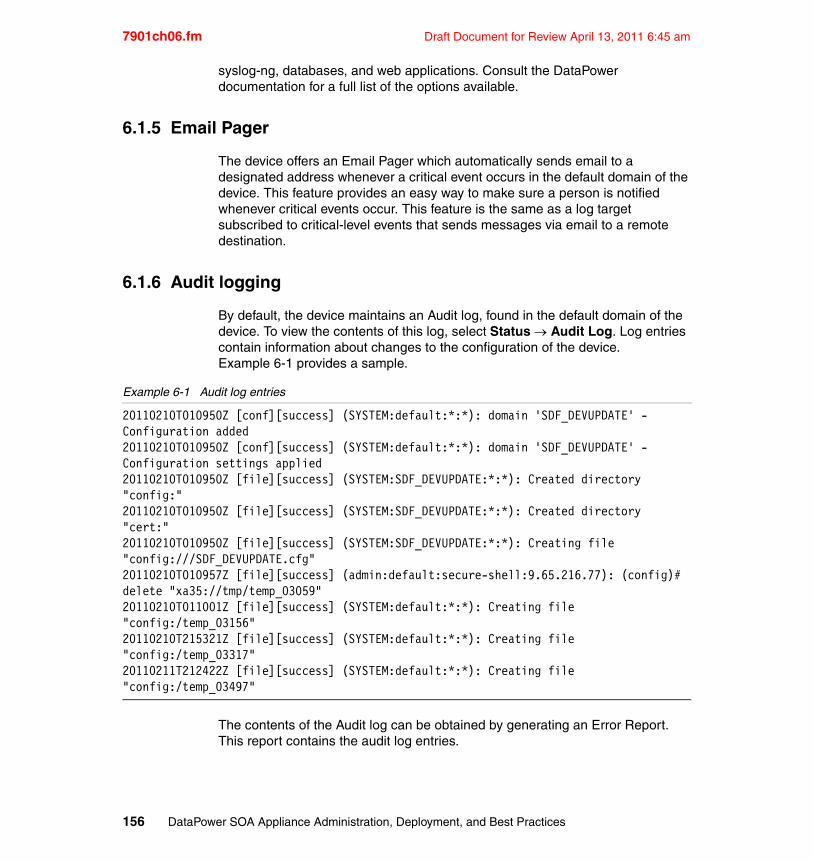
7901ch06.fm Draft Document for Review April 13, 2011 6:45 am
syslog-ng, databases, and web applications. Consult the DataPower documentation for a full list of the options available.
6.1.5 Email Pager
The device offers an Email Pager which automatically sends email to a designated address whenever a critical event occurs in the default domain of the device. This feature provides an easy way to make sure a person is notified whenever critical events occur. This feature is the same as a log target subscribed to critical-level events that sends messages via email to a remote destination.
6.1.6 Audit logging
By default, the device maintains an Audit log, found in the default domain of the device. To view the contents of this log, select Status Audit Log. Log entries contain information about changes to the configuration of the device. Example 6-1 provides a sample.
Example 6-1 Audit log entries
20110210T010950Z [conf][success] (SYSTEM:default:*:*): domain 'SDF_DEVUPDATE' - Configuration added20110210T010950Z [conf][success] (SYSTEM:default:*:*): domain 'SDF_DEVUPDATE' - Configuration settings applied20110210T010950Z [file][success] (SYSTEM:SDF_DEVUPDATE:*:*): Created directory "config:"20110210T010950Z [file][success] (SYSTEM:SDF_DEVUPDATE:*:*): Created directory "cert:"20110210T010950Z [file][success] (SYSTEM:SDF_DEVUPDATE:*:*): Creating file "config:///SDF_DEVUPDATE.cfg"20110210T010957Z [file][success] (admin:default:secure-shell:9.65.216.77): (config)# delete "xa35://tmp/temp_03059"20110210T011001Z [file][success] (SYSTEM:default:*:*): Creating file "config:/temp_03156"20110210T215321Z [file][success] (SYSTEM:default:*:*): Creating file "config:/temp_03317"20110211T212422Z [file][success] (SYSTEM:default:*:*): Creating file "config:/temp_03497"
The contents of the Audit log can be obtained by generating an Error Report. This report contains the audit log entries.
156 DataPower SOA Appliance Administration, Deployment, and Best Practices
Draft Document for Review April 13, 2011 6:45 am 7901ch06.fm
It is also possible to capture much of the same information by creating a log target in the default domain subscribed to the audit, file, and user events. This log target could then be configured to send the log messages off the device as needed.
6.2 Benefits
A robust logging system provides enterprises with a number of benefits, such as the ability to comply with governmental regulations or implement an enterprise auditing policy.
DataPower logging features provide the following benefits:
� Help to track all device activity in its context.
� Provide information needed during application development.
� Provide records needed during normal operation.
� Help isolate failures.
� Maintain records of changes to device configuration.
� Provide immediate notification upon catastrophic events.
6.3 Usage
The logging capabilities of the device offer a great deal of flexibility. The enterprise business requirements regarding logs and records determine the logging methods used for any given deployment. The DataPower device can support the following degrees of reliability in logging:
� Best Effort Event Logging
Log messages are generated and captured as events occur during normal message processing. In the event the device needs the processing power and memory to process transactional messages rather than handling logging, the device will pre-empt the logging system in favor of transactional processes. Log messages may be lost as a result. The standard logging system employing log targets offers this best effort logging.
� Reliable Logging
The device will hold up the processing of messages to ensure that the desired logs are created and delivered as needed to meet the business requirements. The device offers the Log Action, a processing policy action, to accomplish this task. The Log Action, when used in this way, does not employ the
Chapter 6. Logging 157
7901ch06.fm Draft Document for Review April 13, 2011 6:45 am
standard event-driven logging system but rather sends log messages off the device immediately. As defined above, this makes logging part of the transaction processing, and can include a copy of the transaction message in the generated log. This same objective can be reached using a Results Action in the processing policy.
6.4 Event logging
The majority of logging systems implemented on DataPower use the standard event logging system. This is the system that employs log messages, log categories, and log targets. These are the methods used to implement the standard event logging system:
� Create any desired custom log categories� Create any desired log targets� Create any custom log message generators
Each of these topics are covered below.
6.4.1 Create custom log categories
Administrators most often create custom log categories to support the ability to generate custom log messages which are captured by focused log targets. This capability gives administrators and developers the ability to quickly view the log information desired.
Use the following procedure to create a log category.
1. Select Administration Configure Log Categories from the main navigation menu.
2. On the Configure Log Category menu page that displays containing a list of all existing log categories, click Add.
3. On the page that displays, enter the name of the new custom category. Click Apply and then save your configuration.
6.4.2 Create log targets
Most of the key decisions regarding the logging information that needs to be captured on the DataPower system are made while configuring log targets. Such decisions as what logs to keep, when, where, and how to move logging information off of the device, and also what actions to take, if any, when a given event occurs, are implemented through the configuration of log targets.
158 DataPower SOA Appliance Administration, Deployment, and Best Practices
Draft Document for Review April 13, 2011 6:45 am 7901ch06.fm
Use the following procedure to create a log target.
1. Select Administration Manage Log Targets from the main navigation menu.
2. On the Configure Log Targets menu page that appears, containing a list of all existing log targets, click Add.
3. On the Configure Log Target page that displays, enter the name of the new log target.
4. Select the Event Subscriptions tab.
5. Click the Add button.
6. On the Edit Event Subscriptions window that displays, select an event category from the Event Category drop down. You can also specify a priority level using the Minimum Event Priority drop down.
An event subscription designates a log category and also a priority (from debug up to emergency). The device offers a large number of categories, including any custom categories. Only messages that meet the minimum priority level will be captured by the log target.
7. Click Apply to close the window and then click Apply again to save your configuration.
In addition to event subscriptions, log targets offer the ability to create filters of various kinds. Filters restrict the messages captured by the log target. Filters can be any of the following types:
� Event filters
Event filters either include only messages with the designated event code within them or exclude messages with the designated event code within them,
� Object filters
Object filters include only messages published by the selected object class and name. The name can be a wildcard, including all objects of the selected class.
� IP address filters
IP address filters include only those messages with the client IP addresses included in the filters set for this target.
Log targets can also execute a CLI command upon the appearance of an event trigger. Events with a particular log message ID (such as Ox011300006, which indicates failure to establish a backside connection) trigger the execution of a given CLI command. Event triggers are typically used to immediately capture system state information, execute a packet capture or generate an error report.
Chapter 6. Logging 159
7901ch06.fm Draft Document for Review April 13, 2011 6:45 am
Administrators can create any number of log targets. More than one log target can subscribe to the same events.
6.4.3 Create log message generators
In some cases, it is desirable to generate custom log messages, containing exactly the required information. This can be done at any time during the execution of a processing policy by using a Transform action that executes a custom stylesheet. Example 6-2 shows a custom log message.
Example 6-2 Code to generate a custom log message
<xsl:message dp:type="my_category" dp:priority="notice">XYZ just happened during processing</xsl:message>
This message will be caught by any log target subscribed to the my_category event type with a priority of notice or higher. This flexibility makes it possible to include exactly the information desired in a log message.
6.5 Transaction logging
To ensure that the system generates a log message containing the desired information and that this message is delivered successfully to an external repository, the processing policy used to process messages must include either a Log Action or a Results Action. Using either of these actions, it is also possible to include part or all of the message content at any stage of processing.
6.5.1 Log Action
The Log Action sends the contents of its input context to the destination given in the configuration of the action. In addition to the input content, the Log Action adds some additional information and wraps the entire message in a SOAP XML envelope. Example 6-3 shows example output from the Log Action.
Note: Each log target maintains a fixed queue of log events to process. If the arrival rate of messages exceeds this queue, the target may drop messages. Navigate to Status Logging Target to view the number of processed, pending, and dropped events. If this number is large, examine the subscription list.
160 DataPower SOA Appliance Administration, Deployment, and Best Practices
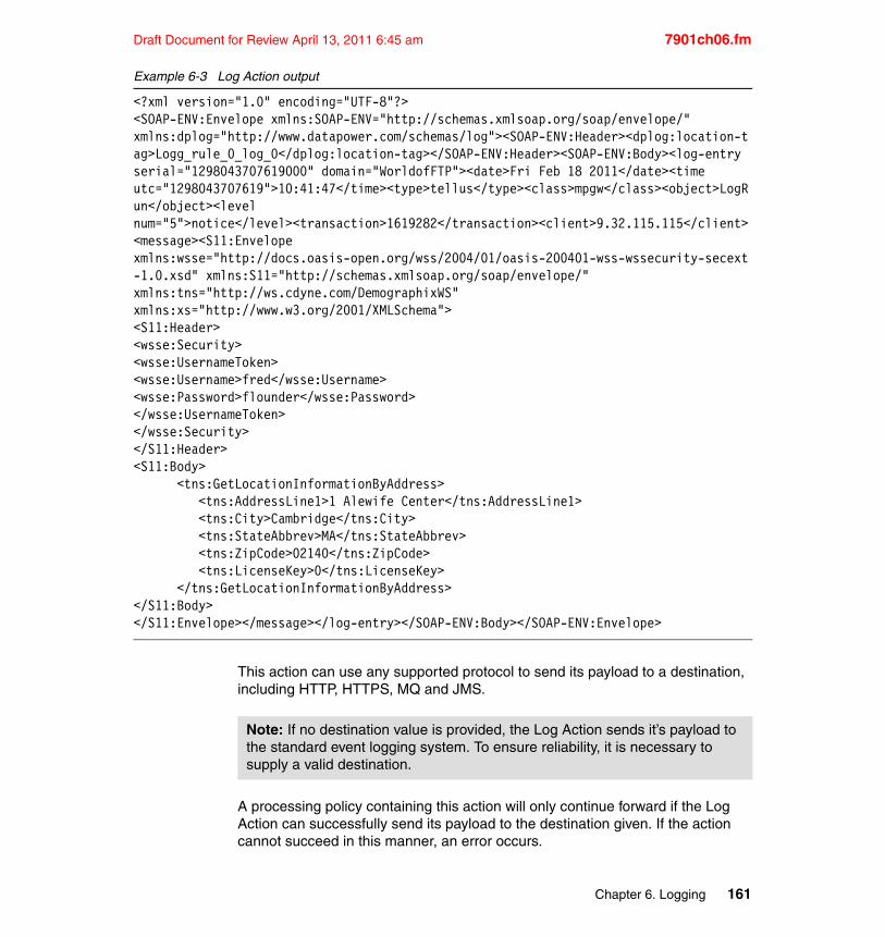
Draft Document for Review April 13, 2011 6:45 am 7901ch06.fm
Example 6-3 Log Action output
<?xml version="1.0" encoding="UTF-8"?><SOAP-ENV:Envelope xmlns:SOAP-ENV="http://schemas.xmlsoap.org/soap/envelope/" xmlns:dplog="http://www.datapower.com/schemas/log"><SOAP-ENV:Header><dplog:location-tag>Logg_rule_0_log_0</dplog:location-tag></SOAP-ENV:Header><SOAP-ENV:Body><log-entry serial="1298043707619000" domain="WorldofFTP"><date>Fri Feb 18 2011</date><time utc="1298043707619">10:41:47</time><type>tellus</type><class>mpgw</class><object>LogRun</object><level num="5">notice</level><transaction>1619282</transaction><client>9.32.115.115</client><message><S11:Envelope xmlns:wsse="http://docs.oasis-open.org/wss/2004/01/oasis-200401-wss-wssecurity-secext-1.0.xsd" xmlns:S11="http://schemas.xmlsoap.org/soap/envelope/" xmlns:tns="http://ws.cdyne.com/DemographixWS" xmlns:xs="http://www.w3.org/2001/XMLSchema"><S11:Header><wsse:Security><wsse:UsernameToken><wsse:Username>fred</wsse:Username><wsse:Password>flounder</wsse:Password></wsse:UsernameToken></wsse:Security></S11:Header><S11:Body> <tns:GetLocationInformationByAddress> <tns:AddressLine1>1 Alewife Center</tns:AddressLine1> <tns:City>Cambridge</tns:City> <tns:StateAbbrev>MA</tns:StateAbbrev> <tns:ZipCode>02140</tns:ZipCode> <tns:LicenseKey>0</tns:LicenseKey> </tns:GetLocationInformationByAddress></S11:Body></S11:Envelope></message></log-entry></SOAP-ENV:Body></SOAP-ENV:Envelope>
This action can use any supported protocol to send its payload to a destination, including HTTP, HTTPS, MQ and JMS.
A processing policy containing this action will only continue forward if the Log Action can successfully send its payload to the destination given. If the action cannot succeed in this manner, an error occurs.
Note: If no destination value is provided, the Log Action sends it’s payload to the standard event logging system. To ensure reliability, it is necessary to supply a valid destination.
Chapter 6. Logging 161
7901ch06.fm Draft Document for Review April 13, 2011 6:45 am
This action will also wait for the configured amount of time (in this case the default timeout value for the URL used) to receive a reply. If no reply is received, the processing policy then continues to completion. The action does not make the response available for further processing.
6.5.2 Results Action
The Results Action sends the content of its input context to a designated destination. Unlike the Log Action, this action does not include any additional information in its payload.
Like the Log Action, the Results Action will cause an error if the attempt to send its payload to the configured destination fails. Like the Log Action, the Results Action will wait for a response for the standard timeout amount of time, if the URL given for the destination expects a response (such as with MQ).
Unlike the Log Action, the Results Action will cause an error if a response is expected and none is received within the timeout amount of time.
6.6 Usage considerations
In addition to those items already mentioned, here are some items to consider when using the DataPower logging system.
� Logging is segregated by application domains. Log targets can only subscribe to messages published by objects in the same application domain. The default system log in the default domain captures all log messages from all domains.
� Log categories are segregated by application domains. Any custom log categories created in one domain are not visible to any other domain, including the default domain.
� The total number of custom log categories created on a device is limited, including all application domains. For firmware versions 3.7.3 and earlier, there is an “appliance-wide” limit of 32 custom Log Categories across all domains. For firmware versions 3.8.0 and higher, there is an “appliance-wide” limit of 175 custom log categories across all domains.
Note: This action must not be marked asynchronous to ensure reliability.
Note: This action must not be marked asynchronous to ensure reliability.
162 DataPower SOA Appliance Administration, Deployment, and Best Practices
Draft Document for Review April 13, 2011 6:45 am 7901ch06.fm
� The device can generate a large volume of log messages in a short amount of time when under load. This can make the log messages sent by the device to a remote server overload that server. When this happens, the DataPower device can begin to slow down as well.
� Event log messages cannot exceed 2 Kbytes in size. Messages larger than 2 Kbytes are truncated.
� Using the Log Action or the Results Action in asynchronous mode can result in excessive resource utilization when the destination becomes unresponsive. Use of asynchronous mode should be avoided if possible.
� It is possible to execute CLI commands on the device when particular log messages are caught by a Log Target with an appropriately configured Event Trigger. This capability allows administrators to automatically generate error reports, run packet captures or even quiesce services with no human intervention. This is very useful during heavy load testing or production environments.
� Some DataPower devices do offer hard drive storage (an option). These hard drives can be used for log files. The persistent storage and larger capacities of the hard drives allow for the creation of larger log files on the device itself. If network latency or processing latency is a concern, consider using hard drive storage for logging. Even when using a hard drive, log files must still be rotated.
6.7 Best practices
This section contains suggested methods for meeting the logging requirements for a range of use case scenarios.
6.7.1 Set log priority levels higher in production environments
The minimum event priority for all active log targets should be set to Warning or higher when a device configuration is moved to production. When log levels are set to Notice or lower in a high-load production environment, the resource demands of logging may become too great for the device to provide the level requested. As previously mentioned, the device places higher priority on message transactions than logging.
6.7.2 Use the default domain for device-wide logging
The default system log in the default domain can capture log messages from all domains on the device. Consider creating specialized log targets in the default
Chapter 6. Logging 163
7901ch06.fm Draft Document for Review April 13, 2011 6:45 am
domain to more readily identify problems that could cross domain boundaries. For example, when an MQ Queue Manager fails or an ODBC connection fails with just a “connection failure” error message in the application domain, the default domain log can show any network, interface, DNS, or other errors that might have affected the connection.
6.7.3 Suppress repeated log messages
Some processes, such as load balancer health checks, generate a large number of identical log messages, thus flooding logs and consuming system resources.
To avoid this condition, it is possible to suppress identical event messages from the same object over a set time period. When enabled, the log target records only one instance of the event until the suppression period expires.
To achieve this configuration, set the Identical Event Detection radio input to On (the default is Off). In the Event Suppression Period field that then appears, enter a value to indicate a suppression period (the default is 10 seconds). Only one instance of identical messages will appear in the logs every 10 seconds. Use a lower suppression period value if this does not meet the enterprise requirement.
6.7.4 Employ a Load Balancer for critical log targets
To ensure the availability of log servers, employ a Load Balancer. The remote destination of any log target would then be set to the address of the Load Balancer rather than a single server.
Using a Load Balancer increases the availability of the logging servers, thus reducing the likelihood that the logging system will become backed up and slow down the device. This becomes particularly useful when the logging system is using TCP to deliver log messages to a destination server. If that server becomes unresponsive and the logging rate is high, the device can consume its protocol stack resources.
It is also possible to use a Load Balancer Group as defined on the device to ensure availability of log servers. In this way, no external balancer is required.
6.7.5 Select the appropriate Syslog server
Syslog servers accept messages over two different IP protocols - TCP and UDP. While the use of the TCP protocol by Syslog-ng servers ensures delivery of each message over the network, this can at times take more time than the rate of
164 DataPower SOA Appliance Administration, Deployment, and Best Practices

Draft Document for Review April 13, 2011 6:45 am 7901ch06.fm
messaging allows. When this happens, consider using the older, UDP-based Syslog service.
6.7.6 Test production logging capacity before deployment
It is good practice to establish the level of logging that can be supported in production environments before a configuration is deployed to production.
When an error condition occurs in production environments, it may be necessary to set logging levels to debug to identify the problem. This setting will generate large volumes of log messages in high load production environments. If the production environment cannot handle such log volumes, another troubleshooting strategy may be needed.
6.7.7 Plan for confidentiality
If the device will process messages that may contain confidential information (such as consumer credit information, health records, or classified government information), and any type of transaction logging is also required, plan for an appropriate logging methodology. Keeping persistent records of such information may violate privacy and security laws in effect.
The event logging system offers the ability to encrypt log messages before the messages are sent off the device, which may meet the privacy requirements that apply. For transaction logging, or any logging that contains a copy of all or part of messages flowing through the device, it may be necessary to encrypt the message content before using an action to send the message off the device.
6.7.8 Manage multiple log target feedback loops
The use of multiple log targets in any configuration can cause the device to cascade log messages endlessly. A log target always suppresses its own events, but will record events from other log targets. Under certain circumstances with multiple log targets, these events could create a positive feedback loop that could cause resource contention.
Enable Feedback Detection when configuring the log target to suppress all log events from the logging subsystem and prevent resource contention.
Chapter 6. Logging 165

7901ch06.fm Draft Document for Review April 13, 2011 6:45 am
166 DataPower SOA Appliance Administration, Deployment, and Best Practices
Draft Document for Review April 13, 2011 6:45 am 7901ch07.fm
Chapter 7. B2B Configuration and Administration
This chapter provides a brief introduction to the WebSphere DataPower B2B Appliance and describes some of the challenges and best practices surrounding the configuration and administration of the B2B appliance.
There are many other configuration and administration considerations with regards to using the B2B appliance however, they are core DataPower challenges that are discussed in other chapters in this book and as such this chapter will only address functionality that is unique to B2B.
7
© Copyright IBM Corp. 2011. All rights reserved. 167
7901ch07.fm Draft Document for Review April 13, 2011 6:45 am
7.1 Introduction to B2B appliances
IBM recognizes the convergence between B2B integration (external integration) and application integration (internal integration) and understands that some integration functions are needed at the edge of the network to support complex B2B flows and to provide greater flexibility for file processing and routing; for this reason the B2B appliance provides the same integration capabilities as our integration appliance allowing our customers to easily and seamlessly bridge external integration and internal integration flows between the DMZ and the protected network.
The WebSphere DataPower B2B Appliance builds upon the functionality in the WebSphere DataPower Application Integration Appliance by adding trading partner profile management, B2B transaction viewing capabilities and industry standards based B2B messaging protocols to the already robust integration capabilities of the core appliance. These three key capabilities are at the heart of the B2B appliance. They are designed in such a way that the B2B appliance is positioned very well to handle simple partner connections with data passing through directly to end applications for further processing. If more complex data flows are required the application integration capabilities of the B2B appliance can be used to perform data validation, transformation, rules based enforcement and content based routing.
The WebSphere DataPower B2B Appliance extends application integration beyond the enterprise by supporting the following B2B functionality:
� EDIINT AS1, AS2, AS3 and ebMS v2.0
� EDI, XML and Binary Payload routing and transformation
� ebXML Collaboration Partner Profile and Agreement (CPPA) v2.0
� MQ File Transfer Edition integration
� Partner Profile Management
� Plaintext e-mail support
� Encrypted B2B payload persistence
� Hard Drive Archive/Purge policy
� Certificate Management (S/MIME Security)
� Multi-step processing policy
� B2B and MQ FTE transaction viewing with optional trading partner visibility
� Transaction event and acknowledgement correlation
� Transaction resend/replay capabilities
168 DataPower SOA Appliance Administration, Deployment, and Best Practices
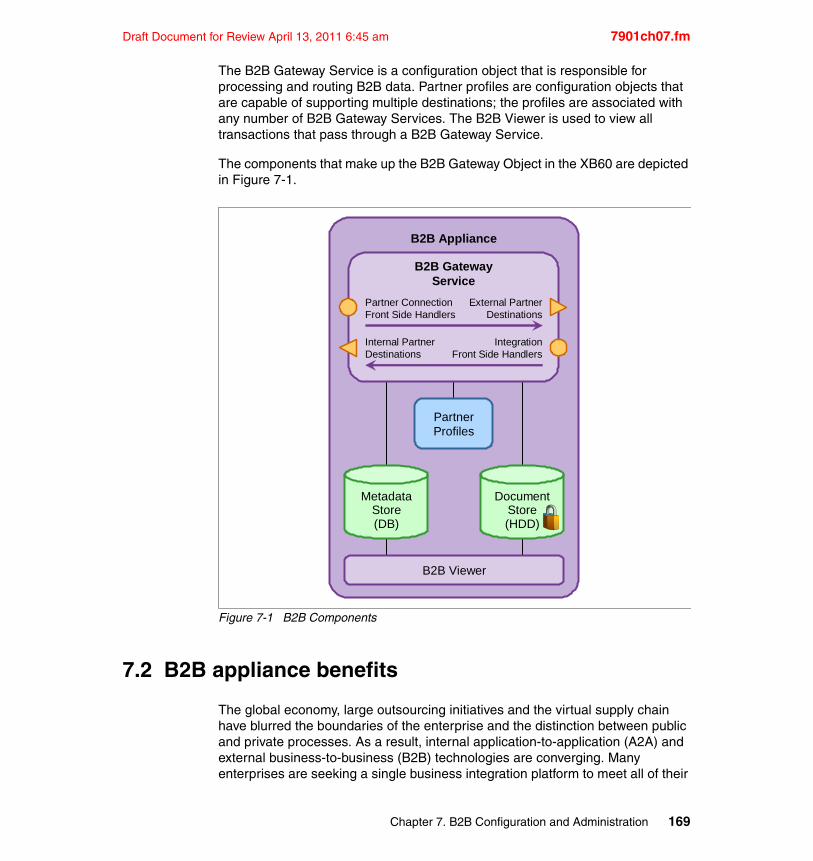
Draft Document for Review April 13, 2011 6:45 am 7901ch07.fm
The B2B Gateway Service is a configuration object that is responsible for processing and routing B2B data. Partner profiles are configuration objects that are capable of supporting multiple destinations; the profiles are associated with any number of B2B Gateway Services. The B2B Viewer is used to view all transactions that pass through a B2B Gateway Service.
The components that make up the B2B Gateway Object in the XB60 are depicted in Figure 7-1.
Figure 7-1 B2B Components
7.2 B2B appliance benefits
The global economy, large outsourcing initiatives and the virtual supply chain have blurred the boundaries of the enterprise and the distinction between public and private processes. As a result, internal application-to-application (A2A) and external business-to-business (B2B) technologies are converging. Many enterprises are seeking a single business integration platform to meet all of their
B2B Appliance
B2B GatewayService
Partner ConnectionFront Side Handlers
Internal PartnerDestinations
External PartnerDestinations
IntegrationFront Side Handlers
PartnerProfiles
MetadataStore(DB)
DocumentStore(HDD)
B2B Viewer
Chapter 7. B2B Configuration and Administration 169

7901ch07.fm Draft Document for Review April 13, 2011 6:45 am
internal and external B2B messaging and integration needs to reduce duplication of effort and the increase speed of 'externalizing' internal processes. The appliance model enables strong B2B business value by accelerating the pace of innovative value-creating processes and strategic initiatives. You can utilize B2B services to quickly and securely connect to your external partners and integrate the partner connections to your application integration flows, all in a purpose built hardware solution.
To take advantage of the improved business processes, flexibility and IT efficiency that come with moving to B2B appliances, organizations require pervasive, scalable services and controls, robust security, and high service assurances in their infrastructures. Today, enterprises often find themselves struggling to deliver these critical requirements without having to handle prohibitive cost, complexity and hard-to-manage infrastructures. Addressing these challenges requires a pragmatic approach; one that simultaneously recognizes the evolution of standards, the value of existing infrastructure investments, your organizational challenges and how security and performance can be affected across applications. The WebSphere DataPower B2B Appliance meets these challenges by providing the key benefits listed below.
� Simplifies SOA deployment by integrating many core functions required for adopting B2B, SOA or Web services into a single, purpose-built device with enterprise service bus (ESB) capability, the B2B appliance simplifies an overall B2B/SOA infrastructure.
� Designed to deploy easily into an existing environment as an in-line network device. You gain business value without having to change your network or application software. As a result, proprietary schemas, coding or application programming interfaces (APIs) are not required to install or manage the device.
� Makes it easier for your partners and customers to do business with you through centralized and consolidated B2B trading partner and transaction management. It provides highly secure connectivity to trading partners over a wide range of protocols, reduces infrastructure costs and increases the speed of on-boarding new partners utilizing a configuration-driven approach that tackles today’s toughest B2B integration challenges.
� Improves the performance and scalability of your B2B deployment by easily integrating disparate transport protocols with no dependencies between inbound “front-side” and outbound “back-side” interfaces.
� Provides front-line defense for both inbound and outbound traffic with high levels of security assurance utilizing AAA Security with integration to a broad range of access control solutions and data security through a broad range of B2B messaging protocols.
170 DataPower SOA Appliance Administration, Deployment, and Best Practices
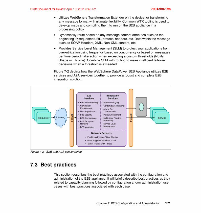
Draft Document for Review April 13, 2011 6:45 am 7901ch07.fm
� Utilizes WebSphere Transformation Extender on the device for transforming any message format with ultimate flexibility. Common WTX tooling is used to develop maps and compiling them to run on the B2B appliance in a processing policy.
� Dynamically route based on any message content attributes such as the originating IP, requested URL, protocol headers, etc. Data within the message such as SOAP Headers, XML, Non-XML content, etc.
� Provides Service Level Management (SLM) to protect your applications from over-utilization using frequency based on concurrency or based on messages per time period; take action when exceeding a custom thresholds (Notify, Shape or Throttle). Combine SLM with routing to make intelligent fail-over decisions when a threshold is exceeded.
Figure 7-2 depicts how the WebSphere DataPower B2B Appliance utilizes B2B services and A2A services together to provide a robust and complete B2B integration solution.
Figure 7-2 B2B and A2A convergence
7.3 Best practices
This section describes the best practices associated with the configuration and administration of the B2B appliance. It will briefly describe best practices as they related to capacity planning followed by configuration and/or administration use cases with best practices associated with each case.
• Partner Provisioning
• Community Management
• Non-Repudiation
• B2B Security
• B2B Acknowledge
• B2B Exception Handling
• B2B Monitoring
• Protocol Bridging
• Content-based Routing
• Any-to-Any Transformation
• Policy Enforcement
• Multi-stage Pipeline Processing
• Service Level Management
B2BServices
IntegrationServices
• IP Address Filtering / Host Aliasing
• VLAN Support / Standby Control
• Packet Trace / SNMP Traps
Network ServicesF
irew
all
Requester Internet Service
Fir
ew
all
Chapter 7. B2B Configuration and Administration 171
7901ch07.fm Draft Document for Review April 13, 2011 6:45 am
7.3.1 Capacity planning
File transferred through the B2B Gateway object are stored on the appliance hard disk and are eventually transferred to a permanent archive. Each B2B Gateway object can have a separate archiving policy, but all B2B Gateway objects together share space on the hard disk. Additionally, metadata that is extracted from each transaction is retained in a separate B2B persistence store on the hard disk.
The archive process removes both copies of messages and message metadata. Archived data cannot be imported into the appliance and cannot be viewed through the Transaction Viewer.
B2B payload storageUp to 70 GB of space on the encrypted portion of the hard drive can be used to store copies of message documents. This space is shared across all B2B Gateway objects. Processing a message generally requires saving a copy of it as it is received “off the wire”, plus a copy of the message after EDIINT or ebMS headers and any S/MIME compression and encryption have been handled. One or more copies of the MDN might also be saved, particularly if asynchronous MDNs are in use.
Metadata storageMetadata from each transaction is held on the appliance in the persistence store, which is on the unencrypted part of the hard disk. This space can be shared with configuration and log files if the appliance is otherwise configured to use the local:///ondisk/ directory. The default setup does not use the hard disk for anything besides B2B message contents and metadata. The B2B Persistence object can be accessed by device administrators in the default domain. Its Storage Size parameter controls the size of the persistence store. The default is 1GB to allow other use of the hard disk. The size can be safely increased to 64 GB.
Note: B2B payloads can optionally be stored off device to either a NFS mount point or on an iSCSI device attached to the network.
Note: After this value is increased, it cannot be decreased. Consider whether you will need to use the appliance hard disk for anything else before increasing the size.
172 DataPower SOA Appliance Administration, Deployment, and Best Practices
Draft Document for Review April 13, 2011 6:45 am 7901ch07.fm
Calculating capacityTo properly plan for archiving and the persistence store size, you need to estimate the traffic characteristics for your appliance.
� How many documents do you expect to receive per day and over what number hours (peek)?
� How large, on average, do you expect these documents to be?
Payload storageFor illustrative purposes, assume 10,000 EDI messages per day with an average size of 10 KB. Therefore, you are expecting 100 MB of content per day. This capacity requires 360 MB of document storage per day, which equates to approximately 84 days.
This corresponds to:
� 200 MB of stored data for these messages. 2 copies of each message -- one copy for "off the wire" and one for the processed request.
� 40 MB (4 KB per message) for protocol responses
� 120 MB for the raw MDN (4 KB per message), HTTP request containing MDN (4 KB per message), and HTTP response containing MDN (4 KB per message)
Metadata storageIf the messages per day are split evenly between inbound and outbound and that every outbound message requests an asynchronous MDN, the space for metadata storage adds up to 15,000 transactions per day, which equates to 60 MB (15000 * 4 KB) of metadata storage per day. At the default 1 GB persistence store size, this will fill in approximately 16 days. If the persistence store is increased to 64 GB, over 1,000 days of message metadata can be persisted.
Using the default persistence store size in this example, setting the Archive Document Age property to 7 days will remove document metadata from the persistence store before it fills.
Note: During testing, transaction metadata appears to require about 4 KB per transaction. One transaction here includes an inbound or outbound file or B2B message. If an outbound message is sent that requests an asynchronous MDN, receipt of that MDN will be processed as a separate transaction that requires separate metadata storage.
Chapter 7. B2B Configuration and Administration 173
7901ch07.fm Draft Document for Review April 13, 2011 6:45 am
WebGUI controlsEach B2B Gateway object has an Archive tab. Each gateway can be independently configured to archive documents and metadata off of the appliance before purging or to purge without archiving.
Relevant settings on the Archive tab include:
� Archive Minimum Size -- Archiving will not occur unless this amount of data is stored in copies of message content
� Archive Document Age -- Documents that were received at least this many days ago will be archived
� Archive Minimum Documents -- Archiving will keep at least this many documents on the appliance after archiving is completed; if fewer than this many documents have been received archiving will not occur
� Disk Use Check Interval -- Specifies how often to check for documents to archive, defaults to hourly Maximum Disk Usage for Documents -- Archiving will occur unconditionally if this amount of data is stored in copies of message content
Commands to monitor spaceYou can use a pair of commands to monitor the disk space and the size of the persistence store.
From the command prompt, type:
Figure 7-3 Commands to monitor B2B drive space
The service show b2bp encrypted-space command shows how much of the 70 GB encrypted disk space the message contents has used.
The service show b2bp size command shows how much space message metadata has used in the persistence store.
7.4 Use cases
This section describes some common configuration use cases with known limitations and best practices for each.
#top#service show b2bp encrypted-space#service show b2bp size
174 DataPower SOA Appliance Administration, Deployment, and Best Practices
Draft Document for Review April 13, 2011 6:45 am 7901ch07.fm
7.4.1 Active/Passive high availability use case
The WebSphere DataPower B2B appliance can be deployed in an Active/Passive High Availability configuration using the standby control functionality native to DataPower devices. Since all of the other services on the device do not persist any data or state information, they will process and pass through all information sent to each of the front-side handlers associated with each of the services. The B2B Gateway service on the primary device maintains state for any B2B messaging protocols that are in use and persists metadata on the primary device for any data it processes and then synchronizes theB2B metadata to the secondary device. In order for synchronization of metadata to work between the two devices, one of the devices must be primary and the other must be secondary; the standby control configuration allows us to provide automatic fail-over to the secondary device in the event the primary device fails and assures the B2B Gateway services on the secondary are not receiving any data. Figure 7-4 on page 176 depicts what a typical active/passive High Availability deployment looks like.
Chapter 7. B2B Configuration and Administration 175
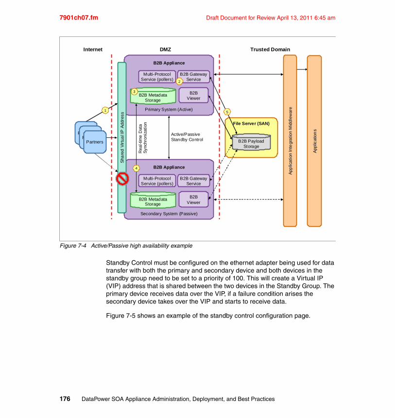
7901ch07.fm Draft Document for Review April 13, 2011 6:45 am
Figure 7-4 Active/Passive high availability example
Standby Control must be configured on the ethernet adapter being used for data transfer with both the primary and secondary device and both devices in the standby group need to be set to a priority of 100. This will create a Virtual IP (VIP) address that is shared between the two devices in the Standby Group. The primary device receives data over the VIP, if a failure condition arises the secondary device takes over the VIP and starts to receive data.
Figure 7-5 shows an example of the standby control configuration page.
PartnersPartners
Internet DMZ Trusted Domain
B2B Appliance
Multi-ProtocolService (pollers)
B2B GatewayService
B2BViewer
Primary System (Active)
Active/PassiveStandby Control
File Server (SAN)
B2B Appliance
Multi-ProtocolService (pollers)
B2B GatewayService
B2BViewer
Secondary System (Passive)
Sha
red
Virt
ual I
P A
ddre
ss
Rea
l-tim
e D
ata
Syn
chro
niza
tion
Partners
B2B MetadataStorage
B2B MetadataStorage
B2B PayloadStorage
App
licat
ion
Inte
grat
ion
Mid
dlew
are
App
licat
ion
s
1
2
3
5
4
176 DataPower SOA Appliance Administration, Deployment, and Best Practices
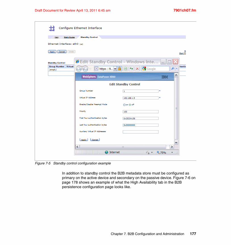
Draft Document for Review April 13, 2011 6:45 am 7901ch07.fm
Figure 7-5 Standby control configuration example
In addition to standby control the B2B metadata store must be configured as primary on the active device and secondary on the passive device. Figure 7-6 on page 178 shows an example of what the High Availability tab in the B2B persistence configuration page looks like.
Chapter 7. B2B Configuration and Administration 177
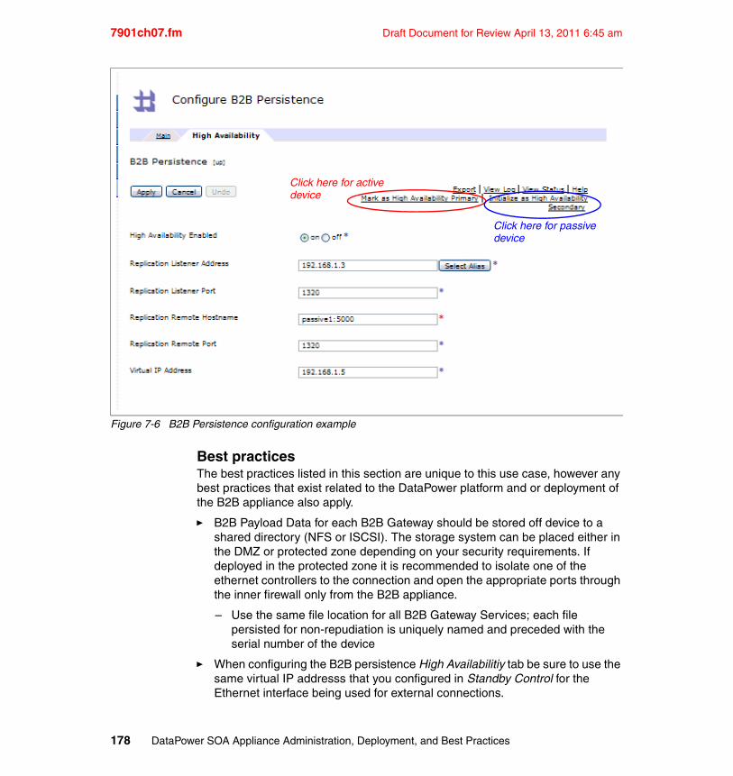
7901ch07.fm Draft Document for Review April 13, 2011 6:45 am
Figure 7-6 B2B Persistence configuration example
Best practicesThe best practices listed in this section are unique to this use case, however any best practices that exist related to the DataPower platform and or deployment of the B2B appliance also apply.
� B2B Payload Data for each B2B Gateway should be stored off device to a shared directory (NFS or ISCSI). The storage system can be placed either in the DMZ or protected zone depending on your security requirements. If deployed in the protected zone it is recommended to isolate one of the ethernet controllers to the connection and open the appropriate ports through the inner firewall only from the B2B appliance.
– Use the same file location for all B2B Gateway Services; each file persisted for non-repudiation is uniquely named and preceded with the serial number of the device
� When configuring the B2B persistence High Availabilitiy tab be sure to use the same virtual IP addresss that you configured in Standby Control for the Ethernet interface being used for external connections.
Click here for active
Click here for passive device
device
178 DataPower SOA Appliance Administration, Deployment, and Best Practices
Draft Document for Review April 13, 2011 6:45 am 7901ch07.fm
� Pollers should not be configured in the B2B Gateways of either the primary or secondary device; they should be configured in a Multi-Protocol Gateway that outputs to the virtual IP Address being used for connectinons from external partners. This ensures that the metadata store on the secondary device does not receive active data from pollers.
� The B2B Gateways and Multi-Protocol Gateways (used for pollers) should be configured identical on both the primary and the secondary devices.
� If using a standby group on the Ethernet interface that is being used for the internal network connection, it is recommended that you use a Multi-Protocol Gateway service to route all transactions originating from the internal network into the virtual IP address associated with the B2B Persistence HA configuration. The best way to do this is to set the output of the Multi-protocol gateway to point to the a HTTP front-side handler in the B2B Gateway service.
� Sharing the same configuration between the two devices is recommended. the most basic way to do this is to export the configuration from the primary device and import it into the secondary device using deployment policies on the secondary device to change any settings specific to the secondary device (e.g. host names, IP addresses, etc.). More information about configuration management techniques and options can be found in Chapter 9, “Configuration management and deployment” on page 191.
LimitationsThe limitations listed in this section are unique to this use case, however any limitations that exist related to the DataPower platform and or deployment of the B2B appliance also apply.
� When B2B payloads are stored off of the device they are not encrypted, it is the responsibility of the network security team to adequately protect all data stored on external Storage Area Networks and/or file servers.
� The passive device is sitting idle until fail-over occurs; The passive system should have an identical configuration as the primary; any usage of the passive system will cause the configuration to be out of sync.
� This solution only provides fail-over and does not provide additional throughput like an active/active configuration does.
� There will be a 1 to 3 second delay during the switch over to the secondary device depending on the network latency of your network.
� Both the primary and secondary device must be installed on the same network subnet.
� Pollers must be configured outside of the B2B Gateway service in pre-processing service that bridges the polling protocol to a http.
Chapter 7. B2B Configuration and Administration 179
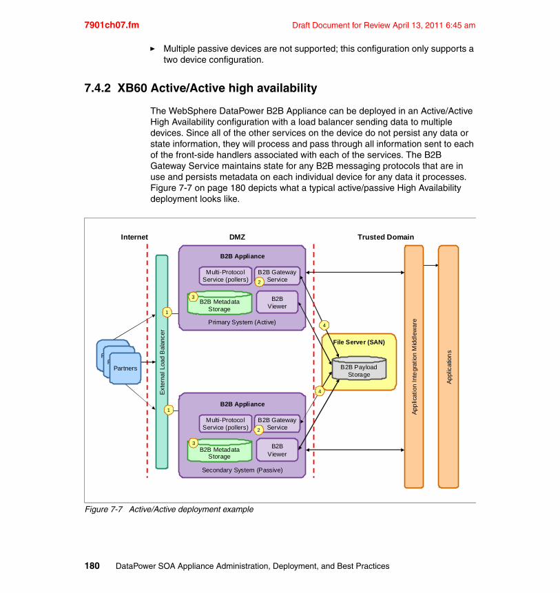
7901ch07.fm Draft Document for Review April 13, 2011 6:45 am
� Multiple passive devices are not supported; this configuration only supports a two device configuration.
7.4.2 XB60 Active/Active high availability
The WebSphere DataPower B2B Appliance can be deployed in an Active/Active High Availability configuration with a load balancer sending data to multiple devices. Since all of the other services on the device do not persist any data or state information, they will process and pass through all information sent to each of the front-side handlers associated with each of the services. The B2B Gateway Service maintains state for any B2B messaging protocols that are in use and persists metadata on each individual device for any data it processes. Figure 7-7 on page 180 depicts what a typical active/passive High Availability deployment looks like.
Figure 7-7 Active/Active deployment example
PartnersPartners
Internet DMZ Trusted Domain
B2B Appliance
Multi-ProtocolService (pollers)
B2B GatewayService
B2BViewer
Primary System (Active)
File Server (SAN)
B2B Appliance
Multi-ProtocolService (pollers)
B2B GatewayService
B2BViewer
Secondary System (Passive)
Ext
erna
l Loa
d B
alan
cer
Partners
B2B MetadataStorage
B2B MetadataStorage
B2B PayloadStorage
App
licat
ion
Inte
grat
ion
Mid
dlew
are
App
licat
ion
s
1
1
2
2
4
4
3
3
180 DataPower SOA Appliance Administration, Deployment, and Best Practices
Draft Document for Review April 13, 2011 6:45 am 7901ch07.fm
Best practicesThe best practices listed in this section are unique to this use case, however any best practices that exist related to the DataPower platform and or deployment of the B2B appliance also apply.
� B2B Payload Data for each B2B Gateway should be stored off device to a shared directory (NFS or ISCSI). The storage system can be placed either in the DMZ or protected zone depending on your security requirements. If deployed in the protected zone it is recommended to isolate one of the ethernet controllers to the connection and open the appropriate ports through the inner firewall only from the B2B appliance.
– Use the same file location for all B2B Gateway Services; each file persisted for non-repudiation is uniquely named and preceded with the serial number of the device.
� Archive B2B Gateway transactions often using the automated archive capabilities of each B2B Gateway service; if any device should fail, the metadata on that device will not be accessible until you restore the machine or place the hard drives into a replacement device.
� Sharing the same configuration between all active nodes is recommended. the most basic way to do this is to export the configuration from the primary device and import it into the secondary device using deployment policies on the secondary device to change any settings specific to the secondary device (e.g. host names, IP addresses, etc.). More information about configuration management techniques and options can be found in Chapter 9, “Configuration management and deployment” on page 191.
� The B2B payload portion of the local hard drives are encrypted at the time of first initialization. If using an active/active deployment and storing the B2B payloads externally, IBM recommends you disable the encryption on the local drive so it can be used for other functions. information on how to disable the AES encryption can be found in the B2B appliance documentation.
LimitationsThe limitations listed in this section are unique to this use case, however any limitations that exist related to the DataPower platform and or deployment of the B2B appliance also apply. When passing data from a load balancer to multiple front-side handlers associated with any B2B Gateway service configured on each device, the following limits and advice should be taken into consideration.
� When B2B payloads are stored off of the device they are not encrypted, it is the responsibility of the network security team to adequately protect all data stored on external Storage Area Networks and/or file servers.
� MDN state is not monitored across multiple devices. When using B2B messaging protocols you must only use synchronous Message Disposition
Chapter 7. B2B Configuration and Administration 181
7901ch07.fm Draft Document for Review April 13, 2011 6:45 am
Notification (MDN) requests or no MDNs at all for outbound message flows. Each device monitors the state of the MDN request and performs an action (reject or resend) if the MDN is not received in the specified period of time.
– AS2 and ebMS have the option of using synchronous MDNs, AS1 and AS3 do not.
– Binary or raw EDI or XML file do not use MDNs and thus are not affected.
– Inbound flows can support synchronous MDN requests from partners since the state of the MDN request is monitored at the sending B2B gateway; the same device that received the MDN request will always process the MDN request.
� Metadata from the B2B Gateway service cannot be stored off device, nor does it synchronize with the metadata store on the any other devices when using an Active/Active deployment, so if you use the B2B Viewer as the primary source to view the state of your transactions you must monitor the transactions on each device separately.
– DataPower has robust logging capabilities that allows you to use custom log categories, event subscriptions, log targets and multi-step to generate the desired events (if they do not already exist) and send the logs/events to a third party monitoring tool that can consume log data (e.g. syslog server, monitoring applications, etc.). This decreases the operational impact of having the metadata stored on multiple devices. More information about logging can be found in Chapter 6, “Logging” on page 153.
182 DataPower SOA Appliance Administration, Deployment, and Best Practices

Draft Document for Review April 13, 2011 6:45 am 7901ch08.fm
Chapter 8. Development life cycle
This chapter discusses the considerations and activities that are associated with a typical DataPower solution life cycle.
Successful implementation is a key objective for projects in the technology industry. However, implementation is also the phase of a project that is associated with the highest level of risk. It requires planning, testing, and forethought to minimize the chance of a failed launch.
As a result, significant effort has been made within the software industry to produce standardized frameworks that outline the development, testing, and release life cycles for projects to minimize this risk. These frameworks or methodologies are implemented by many IT organizations and share common development, deployment, and testing principles.
This chapter discusses the features, considerations, and best practices for implementing DataPower appliances within a life cycle based implementation. It includes the following topics:
� Organizational structure� Software development life cycle� DataPower life cycle stages
8
© Copyright IBM Corp. 2011. All rights reserved. 183
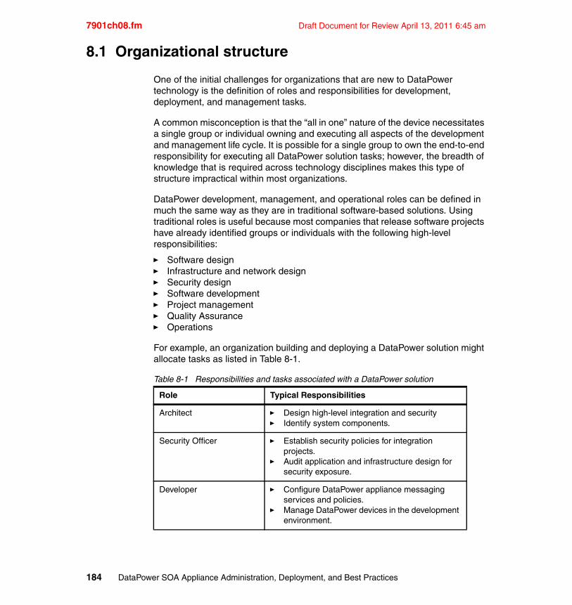
7901ch08.fm Draft Document for Review April 13, 2011 6:45 am
8.1 Organizational structure
One of the initial challenges for organizations that are new to DataPower technology is the definition of roles and responsibilities for development, deployment, and management tasks.
A common misconception is that the “all in one” nature of the device necessitates a single group or individual owning and executing all aspects of the development and management life cycle. It is possible for a single group to own the end-to-end responsibility for executing all DataPower solution tasks; however, the breadth of knowledge that is required across technology disciplines makes this type of structure impractical within most organizations.
DataPower development, management, and operational roles can be defined in much the same way as they are in traditional software-based solutions. Using traditional roles is useful because most companies that release software projects have already identified groups or individuals with the following high-level responsibilities:
� Software design� Infrastructure and network design� Security design� Software development� Project management� Quality Assurance� Operations
For example, an organization building and deploying a DataPower solution might allocate tasks as listed in Table 8-1.
Table 8-1 Responsibilities and tasks associated with a DataPower solution
Role Typical Responsibilities
Architect � Design high-level integration and security� Identify system components.
Security Officer � Establish security policies for integration projects.
� Audit application and infrastructure design for security exposure.
Developer � Configure DataPower appliance messaging services and policies.
� Manage DataPower devices in the development environment.
184 DataPower SOA Appliance Administration, Deployment, and Best Practices
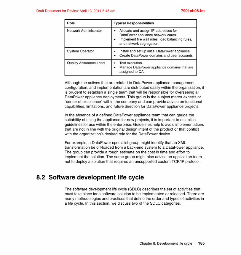
Draft Document for Review April 13, 2011 6:45 am 7901ch08.fm
Although the actives that are related to DataPower appliance management, configuration, and implementation are distributed easily within the organization, it is prudent to establish a single team that will be responsible for overseeing all DataPower appliance deployments. This group is the subject matter experts or “center of excellence” within the company and can provide advice on functional capabilities, limitations, and future direction for DataPower appliance projects.
In the absence of a defined DataPower appliance team that can gauge the suitability of using the appliance for new projects, it is important to establish guidelines for use within the enterprise. Guidelines help to avoid implementations that are not in line with the original design intent of the product or that conflict with the organization’s desired role for the DataPower device.
For example, a DataPower specialist group might identify that an XML transformation be off-loaded from a back-end system to a DataPower appliance. The group can provide a rough estimate on the cost in time and effort to implement the solution. The same group might also advise an application team not to deploy a solution that requires an unsupported custom TCP/IP protocol.
8.2 Software development life cycle
The software development life cycle (SDLC) describes the set of activities that must take place for a software solution to be implemented or released. There are many methodologies and practices that define the order and types of activities in a life cycle. In this section, we discuss two of the SDLC categories.
Network Administrator � Allocate and assign IP addresses for DataPower appliance network cards.
� Implement fire wall rules, load balancing rules, and network segregation.
System Operator � Install and set up initial DataPower appliance.� Create DataPower domains and user accounts.
Quality Assurance Lead � Test execution.� Manage DataPower appliance domains that are
assigned to QA.
Role Typical Responsibilities
Chapter 8. Development life cycle 185
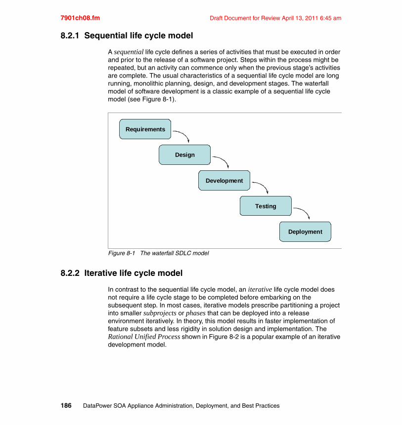
7901ch08.fm Draft Document for Review April 13, 2011 6:45 am
8.2.1 Sequential life cycle model
A sequential life cycle defines a series of activities that must be executed in order and prior to the release of a software project. Steps within the process might be repeated, but an activity can commence only when the previous stage’s activities are complete. The usual characteristics of a sequential life cycle model are long running, monolithic planning, design, and development stages. The waterfall model of software development is a classic example of a sequential life cycle model (see Figure 8-1).
Figure 8-1 The waterfall SDLC model
8.2.2 Iterative life cycle model
In contrast to the sequential life cycle model, an iterative life cycle model does not require a life cycle stage to be completed before embarking on the subsequent step. In most cases, iterative models prescribe partitioning a project into smaller subprojects or phases that can be deployed into a release environment iteratively. In theory, this model results in faster implementation of feature subsets and less rigidity in solution design and implementation. The Rational Unified Process shown in Figure 8-2 is a popular example of an iterative development model.
Requirements
Design
Development
Testing
Deployment
186 DataPower SOA Appliance Administration, Deployment, and Best Practices
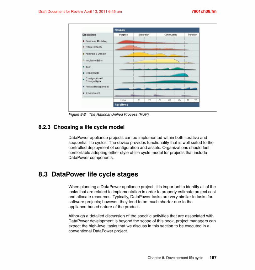
Draft Document for Review April 13, 2011 6:45 am 7901ch08.fm
Figure 8-2 The Rational Unified Process (RUP)
8.2.3 Choosing a life cycle model
DataPower appliance projects can be implemented within both iterative and sequential life cycles. The device provides functionality that is well suited to the controlled deployment of configuration and assets. Organizations should feel comfortable adopting either style of life cycle model for projects that include DataPower components.
8.3 DataPower life cycle stages
When planning a DataPower appliance project, it is important to identify all of the tasks that are related to implementation in order to properly estimate project cost and allocate resources. Typically, DataPower tasks are very similar to tasks for software projects; however, they tend to be much shorter due to the appliance-based nature of the product.
Although a detailed discussion of the specific activities that are associated with DataPower development is beyond the scope of this book, project managers can expect the high-level tasks that we discuss in this section to be executed in a conventional DataPower project.
Chapter 8. Development life cycle 187
7901ch08.fm Draft Document for Review April 13, 2011 6:45 am
8.3.1 Physical installation
Colloquially referred to as “racking and stacking,” physical installation is required only if an existing DataPower device is not available for use within the organization. This task includes the following activities:
� Install the device in development, testing, and production data centers
� Provision power and network connectivity
� Configure the initial system and network, which requires physical access to the device
Roles for this task include the Network Administrator, Systems Operator, and Operations Personnel.
8.3.2 Solution design
Every organization has its own design culture and architectural guidelines; however, the following activities are usually performed when designing a DataPower solution component:
� Identify the integration and security functions that must be implemented to meet the specified requirements
� Conduct a feasibility study to determine if all integration and security functions can be met with existing DataPower hardware and firmware
� Identify the type of DataPower service objects that will support the solution
Roles for this task include the Architect and Developer.
8.3.3 Operational design
In addition to designing a functional solution, it is important to consider all of the nonfunctional aspects of the DataPower appliance installation that we describe in this book. Operational design activities usually include:
� Create a design for systems level monitoring of the device� Create a domain management strategy� Identify operational and deployment tasks that should be automated
Roles for this task include the Architect and Operations Staff.
188 DataPower SOA Appliance Administration, Deployment, and Best Practices
Draft Document for Review April 13, 2011 6:45 am 7901ch08.fm
8.3.4 Development
For DataPower users, development usually entails configuration through the web-based graphical user interface (WebGUI) and construction of associated artifacts. The actual development activities vary from project to project, but in most cases development includes the following activities:
� Configure messaging listeners and services (for example, HTTP Front Side Handlers and WS-Proxy services)
� Configure messaging policies that define how to manage or manipulate in-flight messages
� Construct integration and security artifacts, such as XSL templates
� Test the solution during development
The roles for this task includes the Developer.
8.3.5 Testing
The testing or quality assurance stage in a DataPower solution is identical to a software project testing stage. The only difference for a DataPower project is that the solution is deployed on hardware instead of a software platform. As with any project, testing includes the following activities:
� Construct test cases� Execute test cases� Record issues
The role for this task includes Quality Assurance Personnel.
8.3.6 Deployment
Throughout this book, we discuss strategies for configuration and firmware deployment. At a high level, DataPower deployment includes the following tasks:
� Deploy the firmware� Deploy the configuration� Configure the environment� The role for this task includes the Operations Staff
Chapter 8. Development life cycle 189

7901ch08.fm Draft Document for Review April 13, 2011 6:45 am
190 DataPower SOA Appliance Administration, Deployment, and Best Practices
Draft Document for Review April 13, 2011 6:45 am 7901ch09.fm
Chapter 9. Configuration management and deployment
This chapter covers the practicalities of managing and deploying DataPower configurations within modern IT environments. The specific aspects of configuration management and deployment that will be covered include:
� Utilizing revision control systems
� Developing deployment packages
� Considerations for parallel development
� General deployment strategies
9
Additional information: For additional information about DataPower configuration and deployment, see the IBM WebSphere DataPower Information Center at:
http://publib.boulder.ibm.com/infocenter/wsdatap/v3r8m2/index.jsp
© Copyright IBM Corp. 2011. All rights reserved. 191
7901ch09.fm Draft Document for Review April 13, 2011 6:45 am
9.1 Configuration management
You can configure DataPower device integration and security solutions easily using the web GUI. In addition, the device is designed to support rapid creation of messaging policies. However, this type of hands-on configuration is recommended only for environments in which changes can be made with no risk of impacting existing services. Most commonly, this type of configuration is performed in development and test environments, never in production environments. As with software-based solutions, you need to migrate DataPower appliance configurations from the development environment to the testing and production environments in a controlled and repeatable manner.
9.1.1 Revision control
A key aspect of any software configuration management (SCM) process is revision control. Revision control provides an auditable repository of the assets that are implemented into a target environment and allows an organization to maintain a history of changes that are applied. SCM tools are particularly important for organizations that practice iterative style software development life cycle (SDLC) methodologies in which there are often multiple versions and releases of software to manage at the same time.
There are many SCM tools available on the market today. Most organizations have a favorite (or in some cases a mandated) SCM tool. An effective SCM tool provides support for file versioning, parallel development, audit trails, and integration with development and deployment tools, IBM Rational ClearCase® is an example of a popular software configuration management tool that provides this type of functionality.
It is important to note that there can be multiple SCM tools in use at the same time within a single organization. For example, a development team might use a robust enterprise product for control of source code, while an operations team might maintain a home-grown tool for control of compiled application releases. This type of variation is often a result of the differences in function, budgets, and culture between teams.
Regardless of the specific product that is chosen, DataPower appliance deployments benefit from the use of an SCM. It is strongly recommended that organizations use SCM tooling for any non-trivial implementations.
The following categories of DataPower configuration can benefit from change control:
� System-level configuration
192 DataPower SOA Appliance Administration, Deployment, and Best Practices
Draft Document for Review April 13, 2011 6:45 am 7901ch09.fm
� Development assets� Deployment packages
System-level configurationAs a general rule, system-level configuration covers configuration that is defined within the default domain of the device. For example, the network card configuration, device name, NTP settings, DNS settings, and role-based management settings are all system level configuration items that an administrator should store in a revision control system. This type of configuration is the least likely to change over time, but it is worthwhile storing this information in a change repository in case a device ever needs to be replaced or reconfigured from an initial state.
A revision control process for system-level data can be as primitive as the use of a spreadsheet with all of the relevant system information stored within. However, a simpler and more reliable method is to use the Backup Configuration function to retrieve a compressed file that contains the system-level settings of the device.This backup file can then be stored and versioned as a file within an SCM tool.
In addition, as of firmware version 3.8.1, DataPower administrators can perform a secure backup of the device that includes all of the cryptographic key material from the file system. This feature makes it easier to maintain a complete backup of the device for the purposes of failure recovery.
Development assetsDevelopment assets on a DataPower appliance project include the XML, XSLT, WTX, WSDL, and XSD files that are used within a processing policy. Although these assets can be exported from the device as part of a system backup or domain export, it is prudent to manage each file individually within an SCM tool so that changes to the files can be tracked atomically. This tracking allows for individual files to be versioned as changes are made during the development stage and before the entire project reaches the checkpoint or is labeled for release into the next SDLC stage.
Deployment packagesAlthough revision control of the atomic development assets is useful in a development environment, it is more practical to manage a complete deployment package when migrating to testing and production environments. In the DataPower appliance context, this type of management means using the Export Configuration function to generate a compressed package and storing the entire package in the repository. This function provides the deployment team with a history of deployment packages within the repository and ensures that a domain can be returned to a versioned state by importing the appropriate package.
Chapter 9. Configuration management and deployment 193
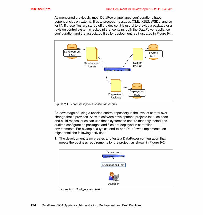
7901ch09.fm Draft Document for Review April 13, 2011 6:45 am
As mentioned previously, most DataPower appliance configurations have dependencies on external flies to process messages (XML, XSLT, WSDL, and so forth). If these files are stored off the device, it is useful to provide a package or a revision control system checkpoint that contains both the DataPower appliance configuration and the associated files for deployment, as illustrated in Figure 9-1.
Figure 9-1 Three categories of revision control
An advantage of using a revision control repository is the level of control over change that it provides. As with software development, projects that use code and build respositories can use these systems to ensure that only tested and audited configuration packages and files are deployed in controlled environments. For example, a typical end-to-end DataPower implementation might entail the following activities:
1. The development team creates and tests a DataPower configuration that meets the business requirements for the project, as shown in Figure 9-2.
Figure 9-2 Configure and test
DevelopmentAssets
SystemBackup
DeploymentPackage
DevelopmentRCS
DeploymentRCS
SystemRCS
Development
Developer
1. Configure and Test
194 DataPower SOA Appliance Administration, Deployment, and Best Practices
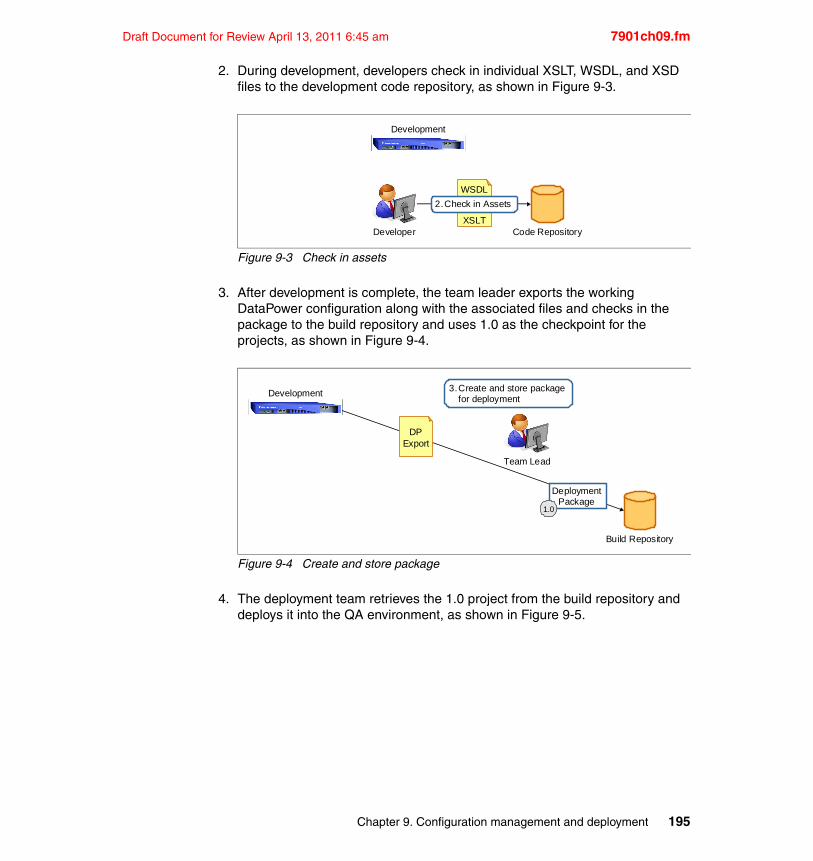
Draft Document for Review April 13, 2011 6:45 am 7901ch09.fm
2. During development, developers check in individual XSLT, WSDL, and XSD files to the development code repository, as shown in Figure 9-3.
Figure 9-3 Check in assets
3. After development is complete, the team leader exports the working DataPower configuration along with the associated files and checks in the package to the build repository and uses 1.0 as the checkpoint for the projects, as shown in Figure 9-4.
Figure 9-4 Create and store package
4. The deployment team retrieves the 1.0 project from the build repository and deploys it into the QA environment, as shown in Figure 9-5.
Developer
Development
WSDL
XSLT
2.Check in Assets
Code Repository
Development
Build Repository
Team Lead
DPExport
3.Create and store packagefor deployment
DeploymentPackage
1.0
Chapter 9. Configuration management and deployment 195
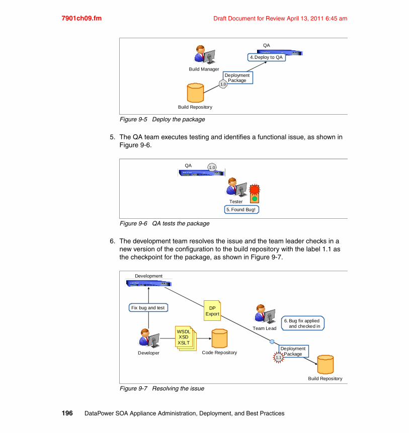
7901ch09.fm Draft Document for Review April 13, 2011 6:45 am
Figure 9-5 Deploy the package
5. The QA team executes testing and identifies a functional issue, as shown in Figure 9-6.
Figure 9-6 QA tests the package
6. The development team resolves the issue and the team leader checks in a new version of the configuration to the build repository with the label 1.1 as the checkpoint for the package, as shown in Figure 9-7.
Figure 9-7 Resolving the issue
QA
Build Manager
4.Deploy to QA
Build Repository
DeploymentPackage
1.0
QA
Tester
5. Found Bug!
1.0
Development
Developer Code Repository
Fix bug and test
WSDLXSDXSLT
Build Repository
DeploymentPackage
1.1
DPExport
Team Lead
6. Bug fix appliedand checked in
196 DataPower SOA Appliance Administration, Deployment, and Best Practices
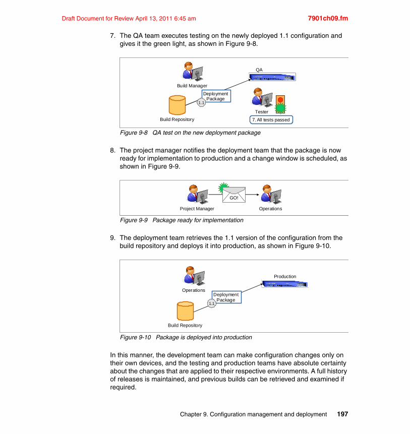
Draft Document for Review April 13, 2011 6:45 am 7901ch09.fm
7. The QA team executes testing on the newly deployed 1.1 configuration and gives it the green light, as shown in Figure 9-8.
Figure 9-8 QA test on the new deployment package
8. The project manager notifies the deployment team that the package is now ready for implementation to production and a change window is scheduled, as shown in Figure 9-9.
Figure 9-9 Package ready for implementation
9. The deployment team retrieves the 1.1 version of the configuration from the build repository and deploys it into production, as shown in Figure 9-10.
Figure 9-10 Package is deployed into production
In this manner, the development team can make configuration changes only on their own devices, and the testing and production teams have absolute certainty about the changes that are applied to their respective environments. A full history of releases is maintained, and previous builds can be retrieved and examined if required.
QA
Tester
7. All tests passed
Build Manager
Build Repository
DeploymentPackage
1.1
Project Manager
GO!
Operations
Production
Operations
Build Repository
DeploymentPackage
1.1
Chapter 9. Configuration management and deployment 197
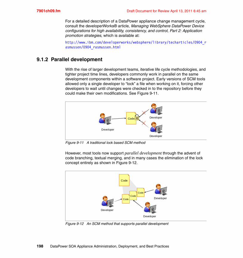
7901ch09.fm Draft Document for Review April 13, 2011 6:45 am
For a detailed description of a DataPower appliance change management cycle, consult the developerWorks® article, Managing WebSphere DataPower Device configurations for high availability, consistency, and control, Part 2: Application promotion strategies, which is available at:
http://www.ibm.com/developerworks/websphere/library/techarticles/0904_rasmussen/0904_rasmussen.html
9.1.2 Parallel development
With the rise of larger development teams, iterative life cycle methodologies, and tighter project time lines, developers commonly work in parallel on the same development components within a software project. Early versions of SCM tools allowed only a single developer to “lock” a file when working on it, forcing other developers to wait until changes were checked in to the repository before they could make their own modifications. See Figure 9-11.
Figure 9-11 A traditional lock based SCM method
However, most tools now support parallel development through the advent of code branching, textual merging, and in many cases the elimination of the lock concept entirely as shown in Figure 9-12.
Figure 9-12 An SCM method that supports parallel development
Developer
Code
Developer
Developer
CodeCode
Code
Developer
Developer
Developer
Code
198 DataPower SOA Appliance Administration, Deployment, and Best Practices
Draft Document for Review April 13, 2011 6:45 am 7901ch09.fm
In practice, parallel development requires a significant amount of planning and foresight to avoid spending inordinate amounts of time resolving merge-related conflicts and bugs. However, when executed properly, the organization can realize a large time savings for development and release activities.
The classic target of parallel or concurrent development is source code files. For example, in a C++ based software development project, multiple developers might need to modify the same C++ source code file at the same time and resolve conflicts when checking the file back into the source code repository.
Although the practice of concurrent development can work well for traditional software development projects, applying this practice to DataPower appliance development can be a challenge. With the DataPower appliance, the configuration instructions for messaging and security policies are not contained within atomic text-based files. Instead, the DataPower device allows users to export configuration as an XML file contained within a compressed package, which makes it difficult to apply most of the automated merge and resolve functionality on which concurrent development projects rely.
In fact, most DataPower users find that the advantages of parallel software development do not translate well to an appliance-based solution. Configuration of a DataPower device takes less time to implement, requires fewer developers, contain fewer bugs, and changes far less than traditional code based development. These advantages result in a shorter development life cycle, which offers far less return on the cost of managing a parallel development practice.
However, if desired, it is still possible to apply a parallel development style to the practice of configuration DataPower devices. The file-based assets, such as XSLT, XSD, and XML files on which DataPower configurations rely, can be developed in parallel easily and do not present a challenge for a build manager. The real complexity arises in managing parallel development of the services, processing policies, and listener objects that are associated with the DataPower web GUI based configuration.
One approach allows individual developers to work in their own domains with a configuration that is exported from the SCM tool. Environment-specific values, such as IP addresses and ports, might need to be modified for each domain, but the actions and the order of operations within the processing policy should remain the same.
Upon completion of a change, the developer is responsible for merging any changes made to the configuration with the official version before checking in the change to the SCM tool. This method entails maintaining a build management or integration test domain for testing merges to ensure that they have not broken the configuration. Configurations can be merged with the import and export facilities that are provided within the device or through a textual merge of the exported
Chapter 9. Configuration management and deployment 199
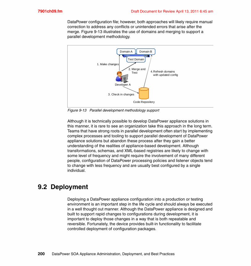
7901ch09.fm Draft Document for Review April 13, 2011 6:45 am
DataPower configuration file; however, both approaches will likely require manual correction to address any conflicts or unintended errors that arise after the merge. Figure 9-13 illustrates the use of domains and merging to support a parallel development methodology.
Figure 9-13 Parallel development methodology support
Although it is technically possible to develop DataPower appliance solutions in this manner, it is rare to see an organization take this approach in the long term. Teams that have strong roots in parallel development often start by implementing complex processes and tooling to support parallel development of DataPower appliance solutions but abandon these process after they gain a better understanding of the realities of appliance-based development. Although transformations, schemas, and XML-based registries are likely to change with some level of frequency and might require the involvement of many different people, configuration of DataPower processing policies and listener objects tend to change with less frequency and are usually best configured by a single individual.
9.2 Deployment
Deploying a DataPower appliance configuration into a production or testing environment is an important step in the life cycle and should always be executed in a well thought out manner. Although the DataPower appliance is designed and built to support rapid changes to configurations during development, it is important to deploy those changes in a way that is both repeatable and reversible. Fortunately, the device provides built-in functionality to facilitate controlled deployment of configuration packages.
2. Merge andTest
Developer A
Test Domain
Code Repository
3. Check in changes
1. Make changes
4.Refresh domainswith updated config
Domain A Domain B
200 DataPower SOA Appliance Administration, Deployment, and Best Practices
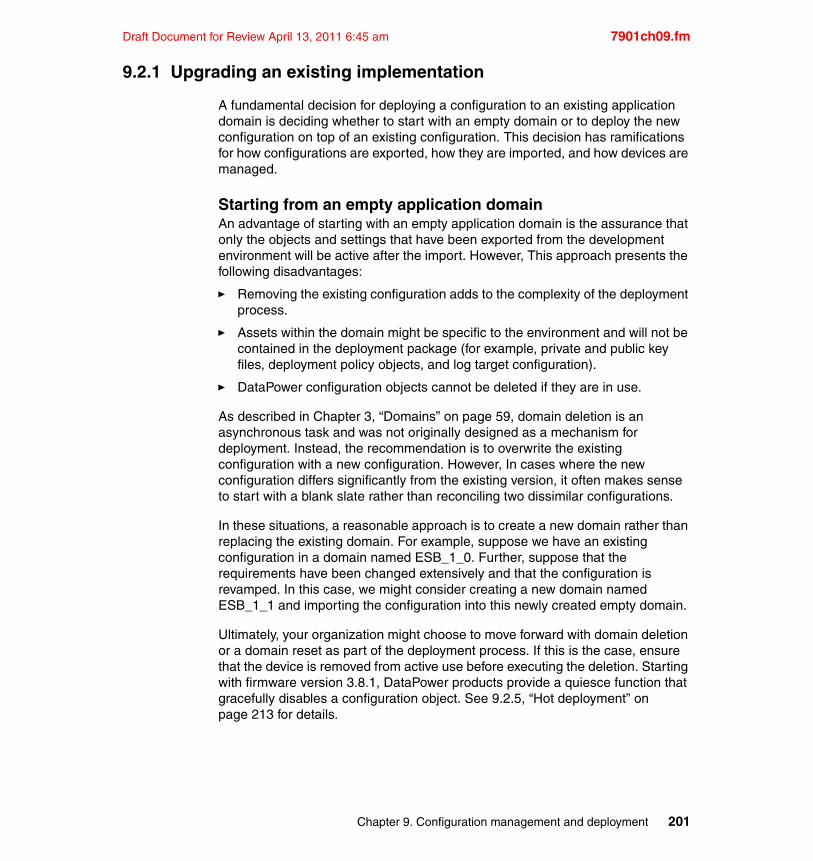
Draft Document for Review April 13, 2011 6:45 am 7901ch09.fm
9.2.1 Upgrading an existing implementation
A fundamental decision for deploying a configuration to an existing application domain is deciding whether to start with an empty domain or to deploy the new configuration on top of an existing configuration. This decision has ramifications for how configurations are exported, how they are imported, and how devices are managed.
Starting from an empty application domainAn advantage of starting with an empty application domain is the assurance that only the objects and settings that have been exported from the development environment will be active after the import. However, This approach presents the following disadvantages:
� Removing the existing configuration adds to the complexity of the deployment process.
� Assets within the domain might be specific to the environment and will not be contained in the deployment package (for example, private and public key files, deployment policy objects, and log target configuration).
� DataPower configuration objects cannot be deleted if they are in use.
As described in Chapter 3, “Domains” on page 59, domain deletion is an asynchronous task and was not originally designed as a mechanism for deployment. Instead, the recommendation is to overwrite the existing configuration with a new configuration. However, In cases where the new configuration differs significantly from the existing version, it often makes sense to start with a blank slate rather than reconciling two dissimilar configurations.
In these situations, a reasonable approach is to create a new domain rather than replacing the existing domain. For example, suppose we have an existing configuration in a domain named ESB_1_0. Further, suppose that the requirements have been changed extensively and that the configuration is revamped. In this case, we might consider creating a new domain named ESB_1_1 and importing the configuration into this newly created empty domain.
Ultimately, your organization might choose to move forward with domain deletion or a domain reset as part of the deployment process. If this is the case, ensure that the device is removed from active use before executing the deletion. Starting with firmware version 3.8.1, DataPower products provide a quiesce function that gracefully disables a configuration object. See 9.2.5, “Hot deployment” on page 213 for details.
Chapter 9. Configuration management and deployment 201
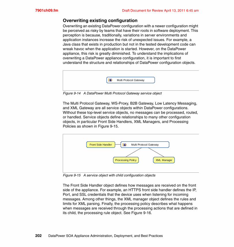
7901ch09.fm Draft Document for Review April 13, 2011 6:45 am
Overwriting existing configurationOverwriting an existing DataPower configuration with a newer configuration might be perceived as risky by teams that have their roots in software deployment. This perception is because, traditionally, variations in server environments and application instances increase the risk of unexpected issues. For example, a Java class that exists in production but not in the tested development code can wreak havoc when the application is started. However, on the DataPower appliance, this risk is greatly diminished. To understand the implications of overwriting a DataPower appliance configuration, it is important to first understand the structure and relationships of DataPower configuration objects.
Figure 9-14 A DataPower Multi Protocol Gateway service object
The Multi Protocol Gateway, WS-Proxy, B2B Gateway, Low Latency Messaging, and XML Gateway are all service objects within DataPower configurations. Without these top-level service objects, no messages can be processed, routed, or handled. Service objects define relationships to many other configuration objects, in particular Front Side Handlers, XML Managers, and Processing Policies as shown in Figure 9-15.
Figure 9-15 A service object with child configuration objects
The Front Side Handler object defines how messages are received on the front side of the appliance. For example, an HTTPS front side handler defines the IP, Port, and SSL credentials that the device uses when listening for incoming messages. Among other things, the XML manager object defines the rules and limits for XML parsing. Finally, the processing policy describes what happens when messages are received through the processing actions that are defined in its child, the processing rule object. See Figure 9-16.
Multi Protocol Gateway
Front Side Handler
Processing Policy XML Manager
Multi Protocol Gateway
202 DataPower SOA Appliance Administration, Deployment, and Best Practices
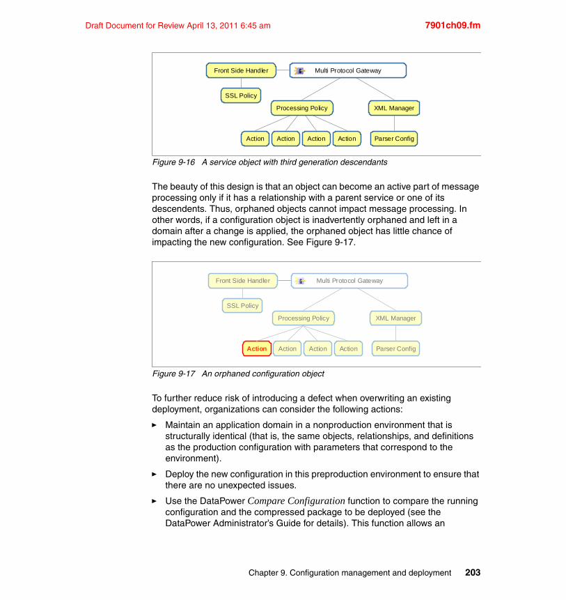
Draft Document for Review April 13, 2011 6:45 am 7901ch09.fm
Figure 9-16 A service object with third generation descendants
The beauty of this design is that an object can become an active part of message processing only if it has a relationship with a parent service or one of its descendents. Thus, orphaned objects cannot impact message processing. In other words, if a configuration object is inadvertently orphaned and left in a domain after a change is applied, the orphaned object has little chance of impacting the new configuration. See Figure 9-17.
Figure 9-17 An orphaned configuration object
To further reduce risk of introducing a defect when overwriting an existing deployment, organizations can consider the following actions:
� Maintain an application domain in a nonproduction environment that is structurally identical (that is, the same objects, relationships, and definitions as the production configuration with parameters that correspond to the environment).
� Deploy the new configuration in this preproduction environment to ensure that there are no unexpected issues.
� Use the DataPower Compare Configuration function to compare the running configuration and the compressed package to be deployed (see the DataPower Administrator’s Guide for details). This function allows an
Front Side Handler
XML Manager
Action Action Action Action
SSL Policy
Parser Config
Processing Policy
Multi Protocol Gateway
Front Side Handler
XML Manager
Action Action Action Action
SSL Policy
Parser Config
Processing Policy
Multi Protocol Gateway
Chapter 9. Configuration management and deployment 203
7901ch09.fm Draft Document for Review April 13, 2011 6:45 am
operations team to identify any unexpected changes or to compare the results with a list of expected changes provided by the application team.
9.2.2 Managing environment specific values
Certain configuration values within a DataPower appliance solution differ, depending on the environment to which it is deployed. For example, a DataPower appliance implementation that protects a back-end web service can route messages to the URL http://mylaptop:8080/test in development but needs to route to http://realserver:8443 in the production environment. The challenge for a DataPower operations team is to ensure a deployed configuration will work within the target environment while avoiding any damage to the integrity of the tested solution.
The following DataPower configuration values typically need to be modified due to environmental dependencies:
� Back-end destination addresses
� External server addresses (including MQ servers, IBM Tivoli Access Manager, and SNMP servers)
� Front Side Handler listener addresses for inbound messages
� Locations for XML, schema, XSLT, and other external files
� Security material (including private keys and keytabs)
� Custom variables that drive environment specific behavior (for example, a flag used to indicate the verbosity of error messages is set to terse in a production environment)
Overall, controlled modification and management of environment values is a common requirement for DataPower administrators, and there are multiple solutions available. Both DataPower appliance configurations and operating environments differ greatly from one user to the next. Thus, it is important to find a solution that fits the organization’s own needs. The risk, complexity, and flexibility of each type of value management solution is a good indicator of solution suitability, and often times it makes sense to combine different strategies to come up with the best fit.
Host name resolutionHost name resolution is a method of resolving a host name to a physical TCP/IP address. For example, in a web browser, the host name www.ibm.com is resolved to its physical IP address of 129.42.60.216.
Name resolution is a simple yet effective way of resolving destination values to environment specific addresses. For example, if a configuration defines a service
204 DataPower SOA Appliance Administration, Deployment, and Best Practices
Draft Document for Review April 13, 2011 6:45 am 7901ch09.fm
with a back-end destination address of http://backend-server:8080/in, the backend-server host name can be resolved to a physical IP address for the hosting environment (assuming that the resolution rules themselves are environment specific).
The Domain Name System (DNS) protocol is the standards-based mechanism that DataPower appliances and almost all computer systems use for host name resolution. The protocol is superficially a client-server messaging protocol and requires the implementation of a DNS server in the operational environment. A DataPower appliance that needs to resolve a host name for a TCP/IP based connection issues a DNS name resolution request to the defined DNS server and uses the IP address that is returned to create the connection. By configuring each DataPower device point to a DNS server that returns an environment-specific IP address, an administrator can avoid making changes to the DataPower configuration package.
Alternatively, the administrator can define name resolution rules in the Host Alias section of the default domain on the appliance. The Host Alias operates similarly to the DNS protocol, except there is no call made to a DNS server. Instead, the DataPower device uses the local name resolution table to resolve the host name to a physical address.
Although name resolution has many advantages, it is limited in scope and addresses only the problem of resolving differences in physical IP destinations. It is not a solution for managing differences in ports, URIs, or object values. For example, name resolution is not the solution for replacing the development back-end destination of http://backend:8080/test with http://backend:8443 in production because the port and URI need to be modified in addition to the IP address.
Post deployment modificationAnother way of compensating for environmental differences is to modify the DataPower configuration values after deploying the original version. For example, if the back-end destination http://mylaptop:8080/test needs to be modified to point to http://realserver:8443, the value itself can be updated to point to the correct destination after the configuration is installed on the device.
When taking this approach, it is crucial that post deployment changes be made in a repeatable, auditable, and reliable way. This method implies that some form of automation is necessary and that the replacement values must be stored and versioned in a repository.
An advantage of applying post deployment modification is the scope of functionality that is available. Any value in the DataPower domain can be
Chapter 9. Configuration management and deployment 205
7901ch09.fm Draft Document for Review April 13, 2011 6:45 am
modified, created, or deleted in some way. However, if not implemented properly, modifying a deployed configuration can have disastrous results.
It is extremely important that the value modification solution is well thought out in order to mitigate the risk of introducing unexpected problems into a critical environment. Due to the level of diligence required, it is often the case that post deployment value modification solutions have a fair degree of complexity in planning, creation and maintenance of the solution.
Predeployment modificationThe flip side of post deployment modification is modification of a configuration package before it is deployed to the target device, which can take one of the following forms:
� Modification of values on a DataPower device prior to export (for example, a development team might replace a back-end destination value of http://mylaptop:8080/test with http://www.service.com/op1 prior to exporting the configuration from the device)
� Modification of the deployment package after exporting it from the device (for example, the use of an XSLT transformation to replace the back-end destination in the export.xml file that is contained in the export package)
� Modification of a remote configuration file (see Chapter 3, “Domains” on page 59 for additional information)
Pre- and post-deployment modification share many of the same characteristics. They both have high degrees of flexibility but also carry the risk of introducing new defects and, thus, tend to be more complex solutions. However, one key difference is that modification of a configuration before deployment allows an organization to have a single asset that represents a deployment package for a particular environment.
In addition to the risks involved when changing configuration, it is important to remember that there is no support, documentation, or official guidance for modification of a configuration file after it is exported from the device. Although the export.xml file that represents the configuration tends to be fairly intuitive, users who decide to modify it need to reverse engineer the configuration data and must accept the risk that the structure and content of the file can be changed without any notice.
Important: There is no official guidance or support for the direct modification of a configuration file. The actual structure of a configuration file can change without notice.
206 DataPower SOA Appliance Administration, Deployment, and Best Practices
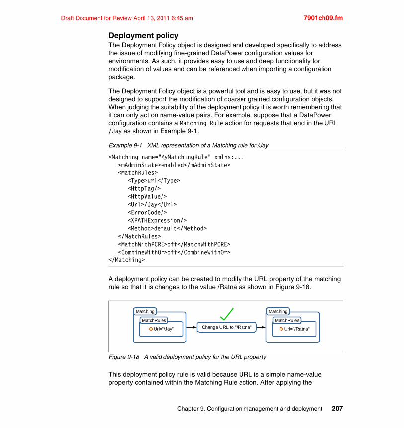
Draft Document for Review April 13, 2011 6:45 am 7901ch09.fm
Deployment policyThe Deployment Policy object is designed and developed specifically to address the issue of modifying fine-grained DataPower configuration values for environments. As such, it provides easy to use and deep functionality for modification of values and can be referenced when importing a configuration package.
The Deployment Policy object is a powerful tool and is easy to use, but it was not designed to support the modification of coarser grained configuration objects. When judging the suitability of the deployment policy it is worth remembering that it can only act on name-value pairs. For example, suppose that a DataPower configuration contains a Matching Rule action for requests that end in the URI /Jay as shown in Example 9-1.
Example 9-1 XML representation of a Matching rule for /Jay
<Matching name="MyMatchingRule" xmlns:...<mAdminState>enabled</mAdminState><MatchRules>
<Type>url</Type><HttpTag/><HttpValue/><Url>/Jay</Url><ErrorCode/><XPATHExpression/><Method>default</Method>
</MatchRules><MatchWithPCRE>off</MatchWithPCRE><CombineWithOr>off</CombineWithOr>
</Matching>
A deployment policy can be created to modify the URL property of the matching rule so that it is changes to the value /Ratna as shown in Figure 9-18.
Figure 9-18 A valid deployment policy for the URL property
This deployment policy rule is valid because URL is a simple name-value property contained within the Matching Rule action. After applying the
Change URL to "/Ratna"
Matching
Url="/Jay"
MatchRules
Matching
Url="/Ratna"
MatchRules
Chapter 9. Configuration management and deployment 207
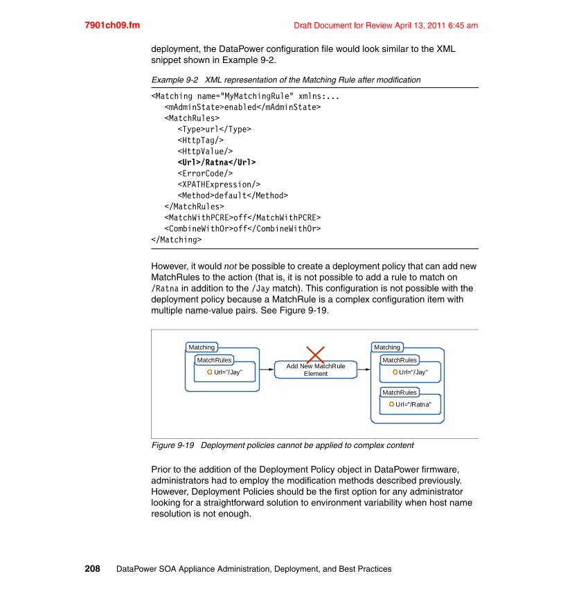
7901ch09.fm Draft Document for Review April 13, 2011 6:45 am
deployment, the DataPower configuration file would look similar to the XML snippet shown in Example 9-2.
Example 9-2 XML representation of the Matching Rule after modification
<Matching name="MyMatchingRule" xmlns:...<mAdminState>enabled</mAdminState><MatchRules>
<Type>url</Type><HttpTag/><HttpValue/><Url>/Ratna</Url><ErrorCode/><XPATHExpression/><Method>default</Method>
</MatchRules><MatchWithPCRE>off</MatchWithPCRE><CombineWithOr>off</CombineWithOr>
</Matching>
However, it would not be possible to create a deployment policy that can add new MatchRules to the action (that is, it is not possible to add a rule to match on /Ratna in addition to the /Jay match). This configuration is not possible with the deployment policy because a MatchRule is a complex configuration item with multiple name-value pairs. See Figure 9-19.
Figure 9-19 Deployment policies cannot be applied to complex content
Prior to the addition of the Deployment Policy object in DataPower firmware, administrators had to employ the modification methods described previously. However, Deployment Policies should be the first option for any administrator looking for a straightforward solution to environment variability when host name resolution is not enough.
Add New MatchRuleElement
Matching
Url="/Jay"
MatchRules
Matching
Url="/Ratna"
MatchRules
Url="/Jay"
MatchRules
208 DataPower SOA Appliance Administration, Deployment, and Best Practices
Draft Document for Review April 13, 2011 6:45 am 7901ch09.fm
Externalizing valuesA final method for dealing with environment-specific values is to externalize the data from the DataPower appliance. For example, a DataPower processing policy package can reference an XML-based routing table that contains a list of back-end destinations. If this routing table file is retrieved from an external source (such as a web server), the DataPower configuration can be deployed without any changes as long as the appropriate resource file is available.
One of the main advantages of this approach is that these values can now be modified without making any changes to the DataPower processing policy or service objects. In fact, this is a useful design pattern in general and is an easy way to minimize the amount of change required on the device itself.
It is important for the external files to be stored in a revision control system along with the associated DataPower configuration so that the environment can be recreated when necessary. In addition, be aware that DataPower policies must be configured to use externalized values. No action (without modification) automatically performs this function.
Readers may wish to consult John Rasmussen's developerWorks article titled Managing WebSphere DataPower SOA Appliance configurations for high availability, consistency, and control, Part 1 for an in depth example of externalizing configuration values through the use of an XML “identity document”. This article is available at:
http://www.ibm.com/developerworks/websphere/library/techarticles/0801_rasmussen/0801_rasmussen.html
Choosing the best methodAll of the methods of managing environment variables that we described in this chapter are used successfully in real DataPower appliance deployments. Development and operations teams need to select the method that fits their own set of requirements based on the configuration that will be deployed and the types of values that need to be modified.
To aid in selecting an appropriate replacement method, administrators can use Table 9-1, which summarizes each scheme according to its risk of introducing defects to the configuration, the complexity of implementing the solution, and its flexibility for handling configuration values:
Table 9-1 Replacement method risk levels
Replacement Method Risk Complexity Flexibility
Host Name Resolution Low Low Low
Chapter 9. Configuration management and deployment 209
7901ch09.fm Draft Document for Review April 13, 2011 6:45 am
9.2.3 Handling PKI material
In many cases, DataPower devices are implemented to protect a backend system or to secure communications with a remote system. In these scenarios it is quite often the case that public key infrastructure (PKI) public and private key files are loaded onto the DataPower appliance for use at run time. Although a public certificate is intended to be distributed freely, the corresponding private key must be closely guarded. If the key were to fall into the wrong hands, the secure nature of the integration will be compromised and the entire solution can be at risk of a malicious attack.
Although DataPower products are not designed to offer an enterprise solution for storing and securing private key material, they do store private key files in an encrypted, write only file system for internal use. Thus, after a private key file is uploaded, imported, or created on a DataPower device, it is almost impossible to view or download that cryptographic material.
The following scenarios provide an exception to this rule:
� If the public and private key pair are created on the appliance itself, there is an option to store both the public and private key files in the temp: directory of the appliance file system. All contents of the temp: directory are deleted automatically after a domain restart, firmware reload, or system restart event.
� The 3.8.1 firmware version supports a conversion function that allows an administrator to export a private key off the device in openSSH public key authentication format, which is primarily useful for sFTP connection handling.
� The 3.8.1 firmware version introduces the secure system backup function that includes key files within a secure backup package.
� DataPower devices that contain the optional hardware security module (HSM) can support extraction of private keys.
Post Deployment Modification Medium Medium High
Pre Deployment Modification High High High
Deployment Policy Low Low Medium
Externalizing Values Low Medium Low
Replacement Method Risk Complexity Flexibility
Private keys: It is essential that private key files are stored in a reliable, secure repository within your organization. The DataPower appliance is not a key storage or distribution system and should not be used as a key repository.
210 DataPower SOA Appliance Administration, Deployment, and Best Practices
Draft Document for Review April 13, 2011 6:45 am 7901ch09.fm
At one time, managing the redeployment of private key files for DataPower disaster recovery was a challenge for administrators. However, the recent improvements provided in firmware version 3.8.1 make the process much easier. Now, administrators can simply export the entire contents of the device including the private key material and store the package in a reliable repository. The key files remain secure because the backup package is encrypted using the public certificate specified by the user. For specific details about the secure backup function, consult the Administrator’s Guide in the online IBM DataPower Information Center.
Although this solves the issue of key deployment for backup and recovery, those organizations who choose to deploy configurations by first wiping out the target application domain need a mechanism for redeploying the private key files to the DataPower appliance. One solution is to avoid deleting the application domain and instead adopt a policy of overwriting changes as described in “Overwriting existing configuration” on page 202. If this method is not possible, an administrator can either re-import cryptographic material or store the files in the sharedcert: directory.
Re-importing private key materialIf desired, private key and public certificate files can either be re-imported to the device manually through the web GUI, or the process of importing can be implemented with automation. Regardless of the method chosen for importing the key files, the real challenge is ensuring that the keys are stored securely while still being accessible to the deployment team.
It is recommended that administrators work closely with their organization’s security team to ensure that any key material deployment solution does not introduce unnecessary risk to the solution.
Using the sharedcert: directory for key materialA more practical option is to store the key material in the sharedcert: directory of the default domain. This directory is a special DataPower directory that can be written to only from the default directory but is shared across all of the application domains on the device. As with the cert: directory, the sharedcert: file system is encrypted and is write-only so that key material cannot be downloaded from the DataPower device.
Because the sharedcert: directory is shared across all domains, special care must be taken with the names of the files to ensure that there are no conflicts. it is also advisable that key and certificate files be password protected due to the fact that they will be accessible within all domains.
Chapter 9. Configuration management and deployment 211
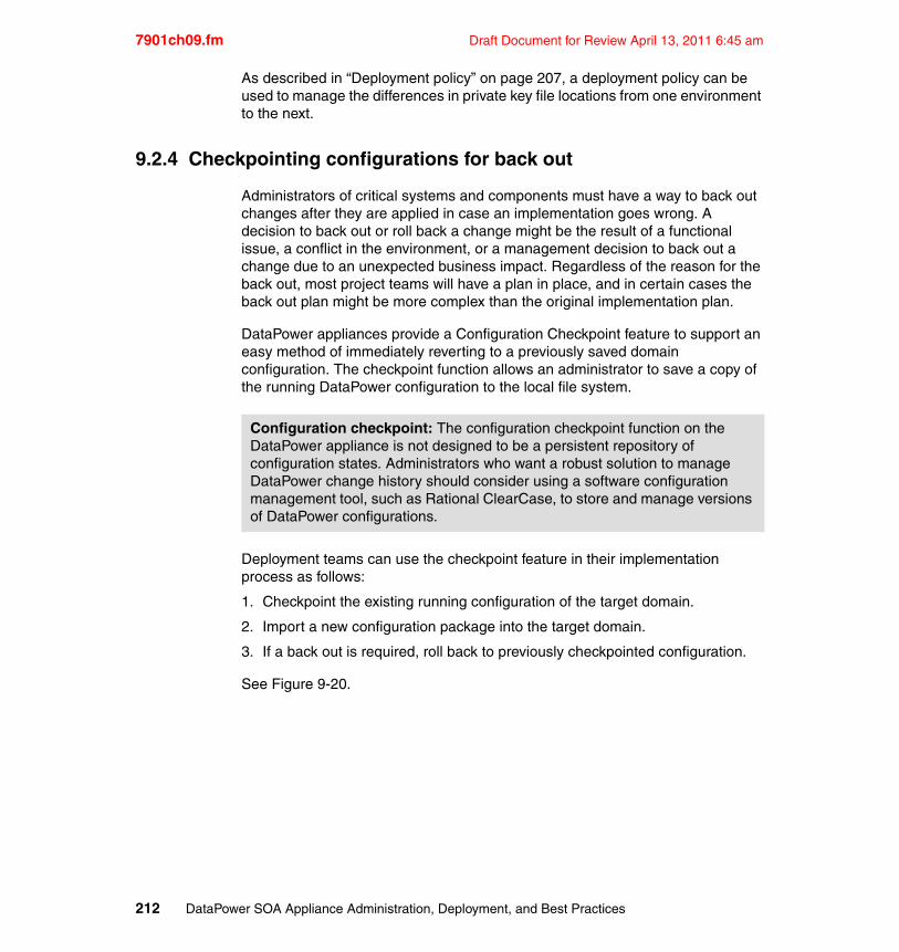
7901ch09.fm Draft Document for Review April 13, 2011 6:45 am
As described in “Deployment policy” on page 207, a deployment policy can be used to manage the differences in private key file locations from one environment to the next.
9.2.4 Checkpointing configurations for back out
Administrators of critical systems and components must have a way to back out changes after they are applied in case an implementation goes wrong. A decision to back out or roll back a change might be the result of a functional issue, a conflict in the environment, or a management decision to back out a change due to an unexpected business impact. Regardless of the reason for the back out, most project teams will have a plan in place, and in certain cases the back out plan might be more complex than the original implementation plan.
DataPower appliances provide a Configuration Checkpoint feature to support an easy method of immediately reverting to a previously saved domain configuration. The checkpoint function allows an administrator to save a copy of the running DataPower configuration to the local file system.
Deployment teams can use the checkpoint feature in their implementation process as follows:
1. Checkpoint the existing running configuration of the target domain.
2. Import a new configuration package into the target domain.
3. If a back out is required, roll back to previously checkpointed configuration.
See Figure 9-20.
Configuration checkpoint: The configuration checkpoint function on the DataPower appliance is not designed to be a persistent repository of configuration states. Administrators who want a robust solution to manage DataPower change history should consider using a software configuration management tool, such as Rational ClearCase, to store and manage versions of DataPower configurations.
212 DataPower SOA Appliance Administration, Deployment, and Best Practices
Draft Document for Review April 13, 2011 6:45 am 7901ch09.fm
Figure 9-20 Checkpointing configurations
Provided that the team had the forethought to use a checkpoint, the roll back feature can be a time saver when backing out a project change. For details about the use of the domain checkpoint functionality, consult the Administrator’s Guide in the DataPower product documentation set.
9.2.5 Hot deployment
A hot deployment is the act of deploying a change to a system component when it is still live. Although it is technically possible to import a configuration into a DataPower device when it is serving traffic, the results are often unpredictable. The immediate risk is that the import process will fail if an attempt is made to update an object that is currently handling a transaction. The additional risk is that the act of updating live configuration objects can inadvertently impact the processing of a message.
The safest way to update the configuration on a DataPower device is to ensure that it is no longer processing messages or transactions. Most operations teams achieve this by removing the device from active service through modification of the network routing infrastructure or by implementing changes during designated service hours. This method is normal practice for most system updates and should not be unique to the practice of DataPower deployment.
In addition, the release of firmware version 3.8.1 introduces a new quiesce feature that lets DataPower administrators drain configuration objects of transactions so that they can be safely modified or deleted. The quiesce function can also be used to stop a service and front side handler from accepting new message requests. For example, an operations team might build a deployment script that first sends a quiesce command to a Web Service Proxy object and its Front Side Handler to ensure that there are no transactions being processed prior to performing a configuration import.
Operator
1.Checkpoint
Operator
2. Import
Operator
3. Problem!
Operator
4.Rollback
!
Chapter 9. Configuration management and deployment 213
7901ch09.fm Draft Document for Review April 13, 2011 6:45 am
Details on the quiesce feature can be found in the Administrator’s Guide within the IBM DataPower Information Center.
9.3 Best practices
As with any complex highly-configurable device, there are some ways of accomplishing certain tasks that are simply better than others. This section provides a basic list of tips and recommendations that have, in most circumstances, proven to be “best practices.” That said, they are not laws and may not be the best in all situations.
� Quiesce domain traffic (using domain quiesce or other means) before making updates to ensure that all message processing jobs are completed.
� Utilize a single administrative user per domain when applying configuration changes to a DataPower appliance. This will help to avoid conflicts when changes are made by multiple users within a single domain.
� Avoid committing many configuration changes all at once, particularly when heavy data traffic is flowing.
� Ensure that the firmware of DataPower devices being targeted for deployment are the same version or higher than the firmware version that was used for the development of the original configuration export.
� Test and validate configurations after making changes or deploying.
� For production or critical domains and devices, schedule a maintenance window so that a controlled migration and test process can be performed before returning the system to active service.
� Track versions of configuration so that changes can be verified and implementations can be rolled back to a known version if necessary.
214 DataPower SOA Appliance Administration, Deployment, and Best Practices
Draft Document for Review April 13, 2011 6:45 am 7901ch10.fm
Chapter 10. Appliance management and automation
In this chapter we will describe the DataPower interfaces that may be used for management and configuration tasks with a special focus on automation.
The following topics will be covered:
� Overview of task automation
� Security considerations
� The Web GUI
� The XML Management Interface
� The WAMT API
� The Command Line Interface (CLI)
10
© Copyright IBM Corp. 2011. All rights reserved. 215
7901ch10.fm Draft Document for Review April 13, 2011 6:45 am
10.1 Task automation
Task automation refers to the replacement of a manual task with a set of automated steps that can be executed repeatedly with minimal human interaction. For example, a scheduled file transfer task may be executed by a human operator, but is often implemented in an automated system instead.
By design, DataPower appliances provide multiple administration interfaces that support automation of management, monitoring and configuration functions. The DataPower appliance can fit into most existing operational and management environments and any task executed via the WebGUI can also be automated.
This provides for automation possibilities that are limited only by the end user’s desire to reduce hands on operation.
10.1.1 The case for automation
Modern organizations prefer repeatable, automated processes to manual ones because they provide the following benefits:
� a reduction in issues resulting from human error
� a restriction of access to critical systems
� a reduced need for resources with specific system and process expertise
� a reduction in operational time and cost
Reducing human errorOccasional errors are both inevitable and unavoidable when using a computer system. While most systems provide user interfaces that are designed to accommodate a small percentage of errors through deletion, undo and back out functionality, the impact of human error when making changes to critical systems can be catastrophic. Examples of human error resulting in disasters can be found throughout history and pose a legitimate risk to any system.
Reducing the steps involved in human-computer interaction to a set of defined instructions that can be executed with a specific set of variables, minimizes the amount of human interaction and in turn, minimizes the overall risk to an organization.
Repeatable processesA benefit of building an automated system is that the set of defined instructions are both repeatable and auditable. Having a truly repeatable process means that behavior is predictable and results achieved when testing a process are more
216 DataPower SOA Appliance Administration, Deployment, and Best Practices
Draft Document for Review April 13, 2011 6:45 am 7901ch10.fm
valuable because the risk of variation is minimal. Repeatability implies improved predictability - an important factor when planning changes to systems or environments that are of a critical nature.
Restricting accessNot only does automation allow organizations to reduce the number of errors resulting from human operation, it also allows them to restrict the type of access that is allowed to critical systems. For example, a human operator with an administrator account can invoke a broad range of management functions, while a human operator with access to an automation system can only invoke the functions that have been automated. Provided that the automation system itself is secured, an automated system provides a reduction in the risk that unauthorized changes will be made to the target system.
A side benefit of automation is that management and monitoring functionality can be rolled out to end users who would not normally be provided with direct access to the system due to the criticality or secure nature of the target system.
Reducing specializationReducing the level of human interaction can also mean reducing the level of specialization required to operate a system. For example, a user may require a certain level of product experience and skill to retrieve memory and CPU utilization from a group of production servers. This dependency on skilled resources limits the availability of the information and can ultimately increase the overall cost for maintenance of the system.
Instead, automating the task of retrieving system metrics to a simple script or program, reduces task complexity and in turn reduces the need for a specialist to be available. Automation can be further extended to take this raw data and present it to non technical users in a more meaningful way - further reducing the dependence on highly skilled, specialized operators.
Reducing time and costPerhaps the biggest motivation amongst systems operators and developers is the time and cost that can be saved by automating monotonous and repetitive tasks. Automation for these types of tasks is usually the easiest to justify and can provide large cost savings for the overall maintenance of a system. This is especially true in environments where multiple systems need to be managed or monitored in the same way.
Chapter 10. Appliance management and automation 217

7901ch10.fm Draft Document for Review April 13, 2011 6:45 am
10.1.2 The case against automation
Deciding which tasks to automate often comes down to determining if the up front effort required to implement an automation script or system is worth the value associated with automating the task or process. While this is ultimately a quantitative judgement call, there are a few scenarios that are generally not good cases for automation:
One-off tasksWhile it may seem obvious that tasks destined to be executed only once or twice are not candidates for automation, there are occasions where a lack of foresight can result in a wasted investment of effort for a task that rarely gets executed. An example would be a script that creates user accounts for an environment that will only ever have a single account.It is important to gain an understanding of the frequency with which a task may be executed prior to spending the effort required to automate it.
Nevertheless, automating a one off task may be justified in environments where the criticality of the system requires that all management and monitoring commands must be automated to avoid any chances of human error.
Scope creep and high levels of complexityAutomation systems that grow too complex can end up becoming more costly to manage and maintain than the manual task it originally replaced. This type of automation often starts life as a simple script to meet a specific set of requirements and grows to become an unmanageable beast through scope creep.
For example, suppose an automation component is built to dynamically generate a DataPower configuration to encrypt messages:
At inception this script might provide immediate value - reducing the time required for the middleware team to release an encrypted messaging proxy and minimizing the level of expertise required. However, if new users demand additional options to meet their own specific requirements, the complexity of the script will rise until it becomes more complex than the original activity it was meant to simplify.
Maintaining the fine balance of providing comprehensive functionality while ensuring that the solution is not overly complex requires vigilance on the part of the automation team. It is worthwhile reviewing automated solutions at regular intervals to ensure that they are still delivering the value for which they were designed and implemented.
218 DataPower SOA Appliance Administration, Deployment, and Best Practices
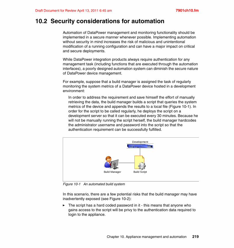
Draft Document for Review April 13, 2011 6:45 am 7901ch10.fm
10.2 Security considerations for automation
Automation of DataPower management and monitoring functionality should be implemented in a secure manner whenever possible. Implementing automation without security in mind increases the risk of malicious and unintentional modification of a running configuration and can have a major impact on critical and secure deployments.
While DataPower integration products always require authentication for any management task (including functions that are executed through the automation interfaces), a poorly designed automation system can diminish the secure nature of DataPower device management.
For example, suppose that a build manager is assigned the task of regularly monitoring the system metrics of a DataPower device hosted in a development environment:
In order to address the requirement and save himself the effort of manually retrieving the data, the build manager builds a script that queries the system metrics of the device and appends the results to a local file (Figure 10-1). In order for the script to be called regularly, he deploys the script on a development server so that it can be executed every 30 minutes. Because he will not be manually running the script herself, the build manager hardcodes the administrator username and password into the script so that the authentication requirement can be successfully fulfilled.
Figure 10-1 An automated build system
In this scenario, there are a few potential risks that the build manager may have inadvertently exposed (see Figure 10-2):
� The script has a hard coded password in it - this means that anyone who gains access to the script will be privy to the authentication data required to login to the appliance.
Development
Build Manager Build Script
Chapter 10. Appliance management and automation 219
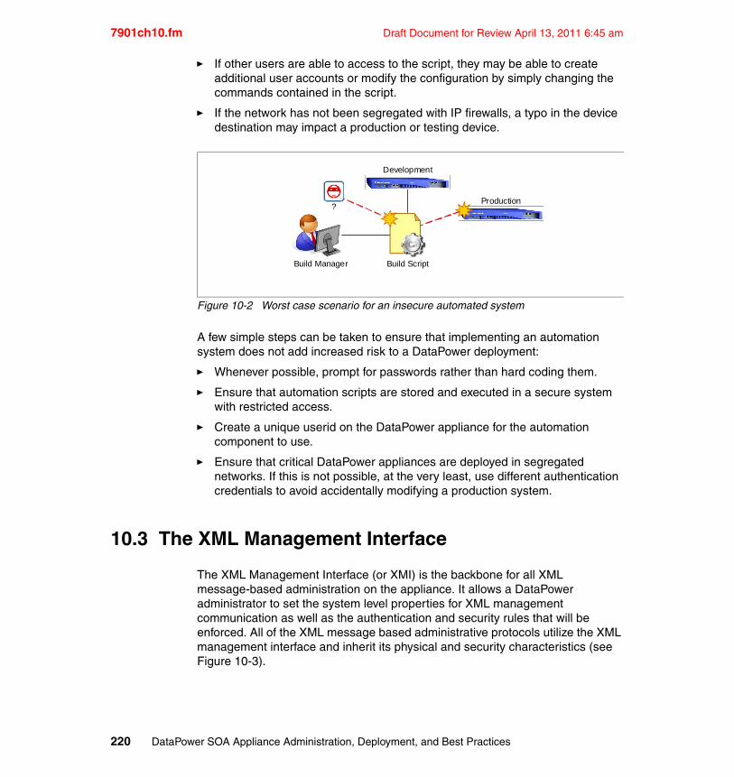
7901ch10.fm Draft Document for Review April 13, 2011 6:45 am
� If other users are able to access to the script, they may be able to create additional user accounts or modify the configuration by simply changing the commands contained in the script.
� If the network has not been segregated with IP firewalls, a typo in the device destination may impact a production or testing device.
Figure 10-2 Worst case scenario for an insecure automated system
A few simple steps can be taken to ensure that implementing an automation system does not add increased risk to a DataPower deployment:
� Whenever possible, prompt for passwords rather than hard coding them.
� Ensure that automation scripts are stored and executed in a secure system with restricted access.
� Create a unique userid on the DataPower appliance for the automation component to use.
� Ensure that critical DataPower appliances are deployed in segregated networks. If this is not possible, at the very least, use different authentication credentials to avoid accidentally modifying a production system.
10.3 The XML Management Interface
The XML Management Interface (or XMI) is the backbone for all XML message-based administration on the appliance. It allows a DataPower administrator to set the system level properties for XML management communication as well as the authentication and security rules that will be enforced. All of the XML message based administrative protocols utilize the XML management interface and inherit its physical and security characteristics (see Figure 10-3).
Development
Build Manager Build Script
Production?
220 DataPower SOA Appliance Administration, Deployment, and Best Practices
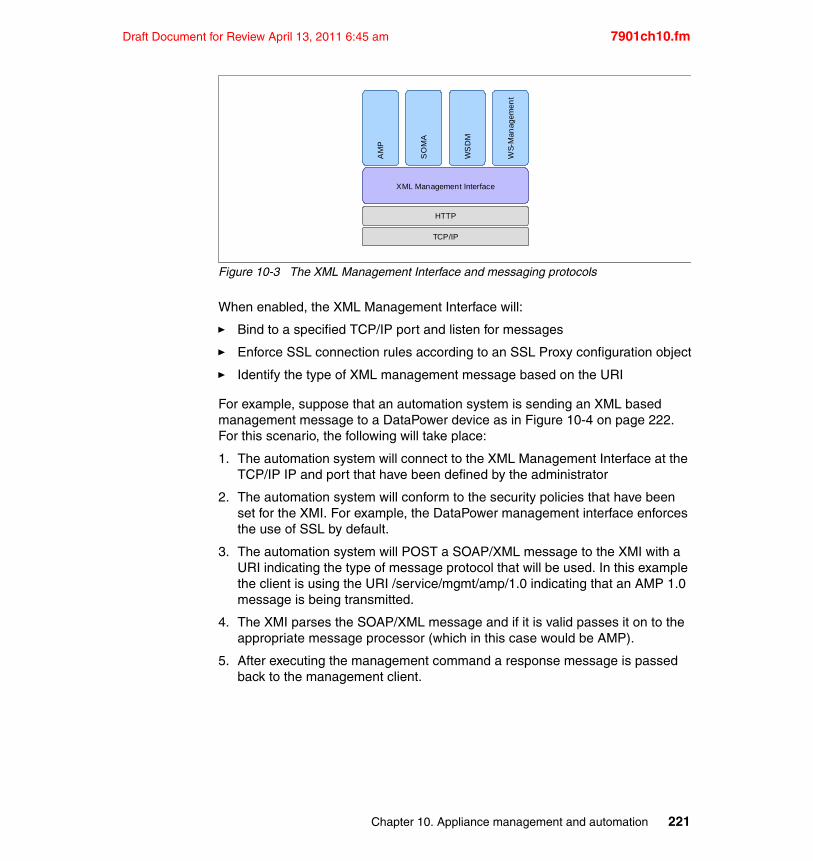
Draft Document for Review April 13, 2011 6:45 am 7901ch10.fm
Figure 10-3 The XML Management Interface and messaging protocols
When enabled, the XML Management Interface will:
� Bind to a specified TCP/IP port and listen for messages
� Enforce SSL connection rules according to an SSL Proxy configuration object
� Identify the type of XML management message based on the URI
For example, suppose that an automation system is sending an XML based management message to a DataPower device as in Figure 10-4 on page 222. For this scenario, the following will take place:
1. The automation system will connect to the XML Management Interface at the TCP/IP IP and port that have been defined by the administrator
2. The automation system will conform to the security policies that have been set for the XMI. For example, the DataPower management interface enforces the use of SSL by default.
3. The automation system will POST a SOAP/XML message to the XMI with a URI indicating the type of message protocol that will be used. In this example the client is using the URI /service/mgmt/amp/1.0 indicating that an AMP 1.0 message is being transmitted.
4. The XMI parses the SOAP/XML message and if it is valid passes it on to the appropriate message processor (which in this case would be AMP).
5. After executing the management command a response message is passed back to the management client.
XML Management Interface
AM
P
SO
MA
WS
DM
WS-
Man
agem
ent
HTTP
TCP/IP
Chapter 10. Appliance management and automation 221
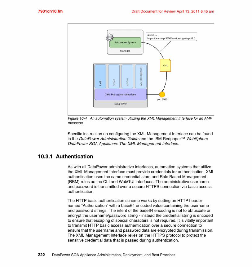
7901ch10.fm Draft Document for Review April 13, 2011 6:45 am
Figure 10-4 An automation system utilizing the XML Management Interface for an AMP message.
Specific instruction on configuring the XML Management Interface can be found in the DataPower Administration Guide and the IBM Redpaper™ WebSphere DataPower SOA Appliance: The XML Management Interface.
10.3.1 Authentication
As with all DataPower administrative interfaces, automation systems that utilize the XML Management Interface must provide credentials for authentication. XMI authentication uses the same credential store and Role Based Management (RBM) rules as the CLI and WebGUI interfaces. The administrative username and password is transmitted over a secure HTTPS connection via basic access authentication.
The HTTP basic authentication scheme works by setting an HTTP header named “Authorization” with a base64 encoded value containing the username and password strings. The intent of the base64 encoding is not to obfuscate or encrypt the username/password string - instead the credential string is encoded to ensure that escaping of special characters is not required. It is vitally important to transmit HTTP basic access authentication over a secure connection to ensure that the username and password data are encrypted during transmission. The XML Management Interface relies on the HTTPS protocol to protect the sensitive credential data that is passed during authentication.
DataPower
XML Management Interface
AM
P
SO
MA
WS
DM
WS
-Ma
nage
men
t
port 5550
Manager
Automation System
POST to:https://device-ip:5550/service/mgmt/app/1.0
XML
222 DataPower SOA Appliance Administration, Deployment, and Best Practices
Draft Document for Review April 13, 2011 6:45 am 7901ch10.fm
Example 10-1 shows the format of an HTTP basic access authentication header.
Example 10-1 Format of HTTP basic authentication header
Authorization: Basic encoded-credential
Prior to encoding, the username and password string is formatted as shown in Example 10-2. It shows how the username and password string should be formatted prior to encoding.
Example 10-2 Format of username and password prior to base64 encoding
username:password
For example, to authenticate with the XML Management Interface using the username ‘Ashy’ and password ‘supplies’, concatenate the username and the password separated by a colon as shown in Example 10-3 on page 223.
Example 10-3 A raw credential string
Ashy:supplies
Next, the raw credential string is encoded using the base64 algorithm to produce an encoded version of the credentials as shown in Example 10-4.
Example 10-4 The base64 encoded credential
QXNoeTpzdXBwbGllcw==
Finally, the HTTP header is set as specified in the HTTP access authentication scheme with the base64 encoded credential data and a token as shown in Example 10-5.
Example 10-5 The completed HTTP authorization header
Authorization: Basic QXNoeTpzdXBwbGllcw==
The HTTP Basic Authentication scheme is a well known and popular standard for transmitting credentials. Most tools, programming languages and scripting
Note: If you are manually creating your credential string for encoding, make sure that there are no CR or LF characters at the end of the credential string. An encoded string that ends with “Cg” is a strong indication that the clear text string ended with a newline character.
Chapter 10. Appliance management and automation 223
7901ch10.fm Draft Document for Review April 13, 2011 6:45 am
platforms will already provide facilities for generating the HTTP headers required based solely on username and password credentials, thus minimizing the effort required to build an automation solution.
Troubleshooting XMI authenticationMost XML management authentication issues can be resolved by enabling the internal logging setting within the Troubleshooting Panel in the default domain.
10.3.2 Appliance Management Protocol (AMP)
The Appliance Management Protocol (or AMP) is an IBM specification designed to be the primary solution for XML based automation of DataPower appliance management functions. While AMP was originally designed and developed for intra-device communication, it is now being heralded as the ideal messaging protocol for automated management of DataPower appliances.
AMP is particularly useful for managing firmware and configuration in multi-box deployments and exposes a comprehensive API of high level management functions.
UsageAMP is exposed on the DataPower appliance as a web service with a WSDL that describes the service, operation and message elements for AMP commands. The app-mgmt-protocol.wsdl and associated app-mgmt-protocol.xsd files are available for download and are located on the appliance’s filesystem within the store directory.
AMP request messages are transmitted to the XML Management Interface over the HTTPS protocol and response messages are returned over the same interface. The format of the request and response messages are described in the WSDL and are designed to be used by WSDL aware tools to quickly generate AMP messages. The sample AMP message shown in Example 10-6 illustrates a request message that retrieves the list of domains from a DataPower appliance.
Example 10-6 AMP message to retrieve existing domains
<env:Envelope xmlns:env="http ...omitted... agement/1.0"><env:Header/><env:Body>
<ns:GetDomainListRequest/></env:Body>
</env:Envelope>
224 DataPower SOA Appliance Administration, Deployment, and Best Practices
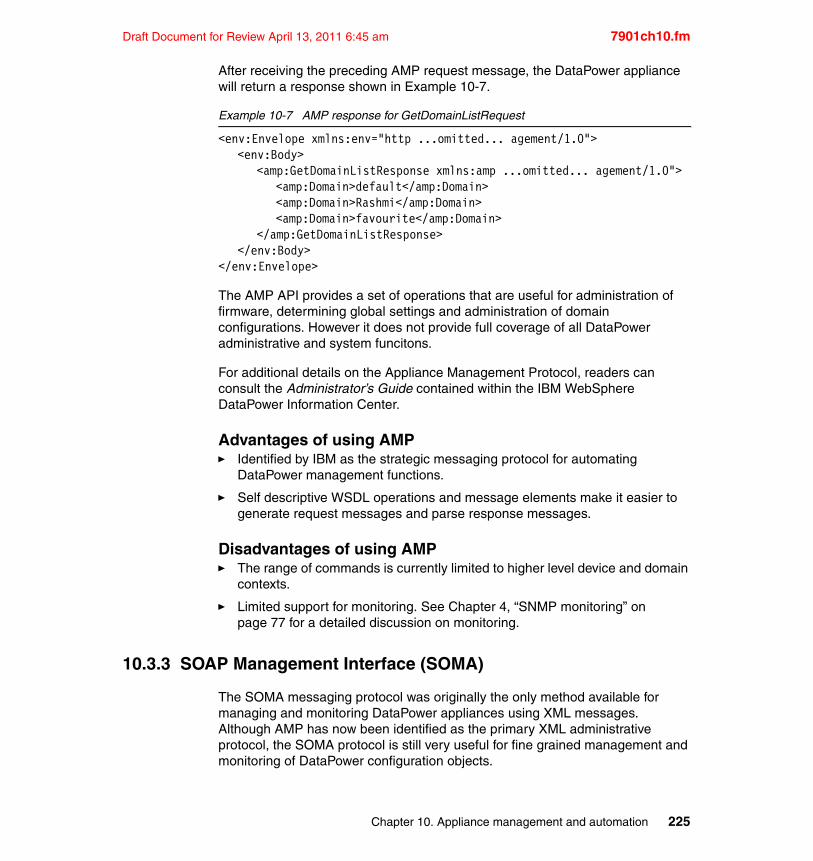
Draft Document for Review April 13, 2011 6:45 am 7901ch10.fm
After receiving the preceding AMP request message, the DataPower appliance will return a response shown in Example 10-7.
Example 10-7 AMP response for GetDomainListRequest
<env:Envelope xmlns:env="http ...omitted... agement/1.0"><env:Body>
<amp:GetDomainListResponse xmlns:amp ...omitted... agement/1.0"><amp:Domain>default</amp:Domain><amp:Domain>Rashmi</amp:Domain><amp:Domain>favourite</amp:Domain>
</amp:GetDomainListResponse></env:Body>
</env:Envelope>
The AMP API provides a set of operations that are useful for administration of firmware, determining global settings and administration of domain configurations. However it does not provide full coverage of all DataPower administrative and system funcitons.
For additional details on the Appliance Management Protocol, readers can consult the Administrator’s Guide contained within the IBM WebSphere DataPower Information Center.
Advantages of using AMP� Identified by IBM as the strategic messaging protocol for automating
DataPower management functions.
� Self descriptive WSDL operations and message elements make it easier to generate request messages and parse response messages.
Disadvantages of using AMP� The range of commands is currently limited to higher level device and domain
contexts.
� Limited support for monitoring. See Chapter 4, “SNMP monitoring” on page 77 for a detailed discussion on monitoring.
10.3.3 SOAP Management Interface (SOMA)
The SOMA messaging protocol was originally the only method available for managing and monitoring DataPower appliances using XML messages. Although AMP has now been identified as the primary XML administrative protocol, the SOMA protocol is still very useful for fine grained management and monitoring of DataPower configuration objects.
Chapter 10. Appliance management and automation 225
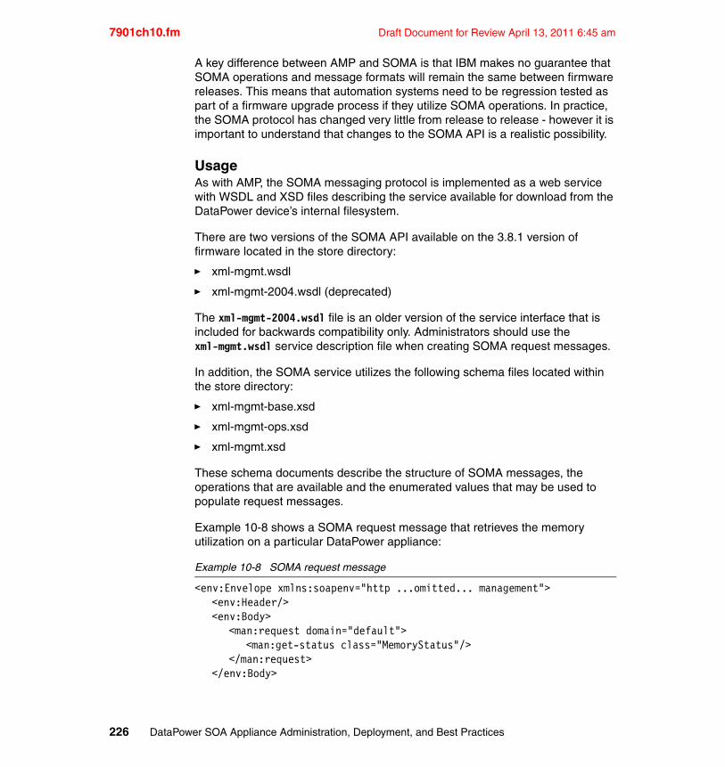
7901ch10.fm Draft Document for Review April 13, 2011 6:45 am
A key difference between AMP and SOMA is that IBM makes no guarantee that SOMA operations and message formats will remain the same between firmware releases. This means that automation systems need to be regression tested as part of a firmware upgrade process if they utilize SOMA operations. In practice, the SOMA protocol has changed very little from release to release - however it is important to understand that changes to the SOMA API is a realistic possibility.
UsageAs with AMP, the SOMA messaging protocol is implemented as a web service with WSDL and XSD files describing the service available for download from the DataPower device’s internal filesystem.
There are two versions of the SOMA API available on the 3.8.1 version of firmware located in the store directory:
� xml-mgmt.wsdl
� xml-mgmt-2004.wsdl (deprecated)
The xml-mgmt-2004.wsdl file is an older version of the service interface that is included for backwards compatibility only. Administrators should use the xml-mgmt.wsdl service description file when creating SOMA request messages.
In addition, the SOMA service utilizes the following schema files located within the store directory:
� xml-mgmt-base.xsd
� xml-mgmt-ops.xsd
� xml-mgmt.xsd
These schema documents describe the structure of SOMA messages, the operations that are available and the enumerated values that may be used to populate request messages.
Example 10-8 shows a SOMA request message that retrieves the memory utilization on a particular DataPower appliance:
Example 10-8 SOMA request message
<env:Envelope xmlns:soapenv="http ...omitted... management"><env:Header/><env:Body>
<man:request domain="default"><man:get-status class="MemoryStatus"/>
</man:request></env:Body>
226 DataPower SOA Appliance Administration, Deployment, and Best Practices
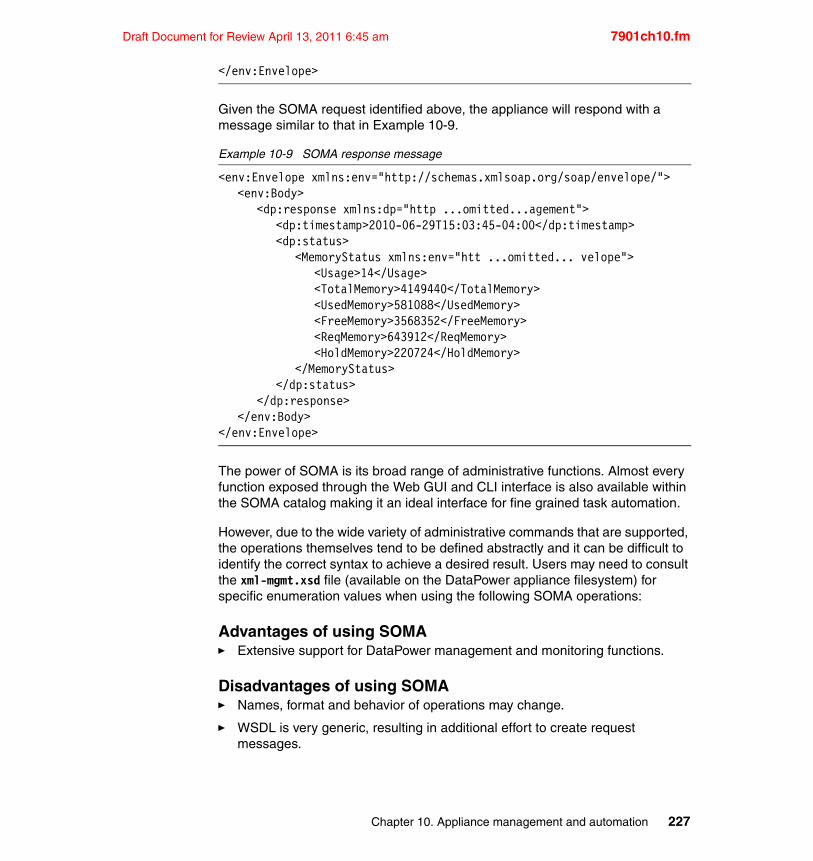
Draft Document for Review April 13, 2011 6:45 am 7901ch10.fm
</env:Envelope>
Given the SOMA request identified above, the appliance will respond with a message similar to that in Example 10-9.
Example 10-9 SOMA response message
<env:Envelope xmlns:env="http://schemas.xmlsoap.org/soap/envelope/"><env:Body>
<dp:response xmlns:dp="http ...omitted...agement"><dp:timestamp>2010-06-29T15:03:45-04:00</dp:timestamp><dp:status>
<MemoryStatus xmlns:env="htt ...omitted... velope"><Usage>14</Usage><TotalMemory>4149440</TotalMemory><UsedMemory>581088</UsedMemory><FreeMemory>3568352</FreeMemory><ReqMemory>643912</ReqMemory><HoldMemory>220724</HoldMemory>
</MemoryStatus></dp:status>
</dp:response></env:Body>
</env:Envelope>
The power of SOMA is its broad range of administrative functions. Almost every function exposed through the Web GUI and CLI interface is also available within the SOMA catalog making it an ideal interface for fine grained task automation.
However, due to the wide variety of administrative commands that are supported, the operations themselves tend to be defined abstractly and it can be difficult to identify the correct syntax to achieve a desired result. Users may need to consult the xml-mgmt.xsd file (available on the DataPower appliance filesystem) for specific enumeration values when using the following SOMA operations:
Advantages of using SOMA� Extensive support for DataPower management and monitoring functions.
Disadvantages of using SOMA� Names, format and behavior of operations may change.
� WSDL is very generic, resulting in additional effort to create request messages.
Chapter 10. Appliance management and automation 227
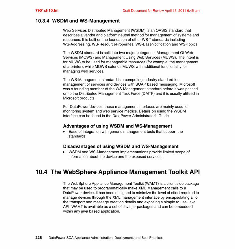
7901ch10.fm Draft Document for Review April 13, 2011 6:45 am
10.3.4 WSDM and WS-Management
Web Services Distributed Management (WSDM) is an OASIS standard that describes a vendor and platform neutral method for management of systems and resources. It is built on the foundation of other WS-* standards including WS-Addressing, WS-ResourceProperites, WS-BaseNotification and WS-Topics.
The WSDM standard is split into two major categories: Management Of Web Services (MOWS) and Management Using Web Services (MUWS). The intent is for MUWS to be used for manageable resources (for example, the management of a printer), while MOWS extends MUWS with additional functionality for managing web services.
The WS-Management standard is a competing industry standard for management of services and devices with SOAP based messaging. Microsoft was a founding member of the WS-Management standard before it was passed on to the Distributed Management Task Force (DMTF) and it is usually utilized in Microsoft products.
For DataPower devices, these management interfaces are mainly used for monitoring system and web service metrics. Details on using the WSDM interface can be found in the DataPower Administrator’s Guide
Advantages of using WSDM and WS-Management� Ease of integration with generic management tools that support the
standards.
Disadvantages of using WSDM and WS-Management� WSDM and WS-Management implementations provide limited scope of
information about the device and the exposed services.
10.4 The WebSphere Appliance Management Toolkit API
The WebSphere Appliance Management Toolkit (WAMT) is a client side package that may be used to programmatically make XML Management calls to a DataPower device. It has been designed to minimize the level of effort required to manage devices through the XML management interface by encapsulating all of the transport and message creation details and exposing a simple to use Java API. WAMT is available as a set of Java jar packages and can be embedded within any java based application.
228 DataPower SOA Appliance Administration, Deployment, and Best Practices
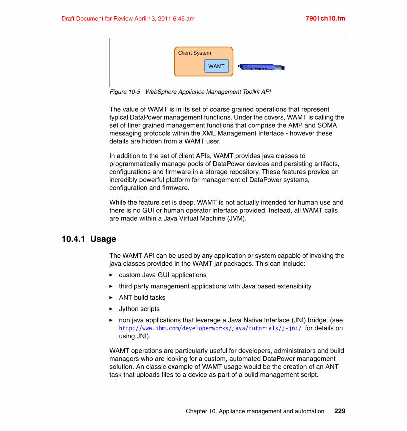
Draft Document for Review April 13, 2011 6:45 am 7901ch10.fm
Figure 10-5 WebSphere Appliance Management Toolkit API
The value of WAMT is in its set of coarse grained operations that represent typical DataPower management functions. Under the covers, WAMT is calling the set of finer grained management functions that comprise the AMP and SOMA messaging protocols within the XML Management Interface - however these details are hidden from a WAMT user.
In addition to the set of client APIs, WAMT provides java classes to programmatically manage pools of DataPower devices and persisting artifacts, configurations and firmware in a storage repository. These features provide an incredibly powerful platform for management of DataPower systems, configuration and firmware.
While the feature set is deep, WAMT is not actually intended for human use and there is no GUI or human operator interface provided. Instead, all WAMT calls are made within a Java Virtual Machine (JVM).
10.4.1 Usage
The WAMT API can be used by any application or system capable of invoking the java classes provided in the WAMT jar packages. This can include:
� custom Java GUI applications
� third party management applications with Java based extensibility
� ANT build tasks
� Jython scripts
� non java applications that leverage a Java Native Interface (JNI) bridge. (see http://www.ibm.com/developerworks/java/tutorials/j-jni/ for details on using JNI).
WAMT operations are particularly useful for developers, administrators and build managers who are looking for a custom, automated DataPower management solution. An classic example of WAMT usage would be the creation of an ANT task that uploads files to a device as part of a build management script.
Client System
WAMT
Chapter 10. Appliance management and automation 229
7901ch10.fm Draft Document for Review April 13, 2011 6:45 am
The WAMT library automatically takes advantage of the management subscription capability provided in AMP. This means that there is less risk of conflicts when duplicate WAMT based managers are operating on the same device.
Users can consult the javadoc included with the WAMT package for a complete reference of operations that are available. At a high level, the WAMT management functions are similar to the ones exposed by AMP and include operations for domain management, disaster recovery and device synchronization.
10.4.2 Advantages of using WAMT
� Transport, messaging and finer grained operations are hidden.
� Covers complete range of high level firmware, system and configuration management functions.
10.4.3 Disadvantages of using WAMT
� Requires JVM based solution.
� Abstraction of DataPower API calls may result in less flexibility for user.
10.5 Command Line Interface automation
The command line interface (or CLI) is a terminal based interface that allows a DataPower operator to create, manage and monitor appliance configurations. It is usually accessed through the secure shell (ssh) protocol, however it can also be accessed via telnet or a direct serial connection.
While not originally designed or intended to be used for automation, it is possible to script shell commands that mimic human command entry and parse the response provided by the appliance to systematically determine the result of the issued command
Note: The CLI interface is not designed for automation and there is no guarantee that the interface will remain the same. Users should be aware that it is possible for support, syntax and results of commands to differ between firmware releases.
230 DataPower SOA Appliance Administration, Deployment, and Best Practices
Draft Document for Review April 13, 2011 6:45 am 7901ch10.fm
10.5.1 Authentication
The CLI uses the same authentication scheme and credential store as the XML Management and Web GUI management interfaces. Users must enter their username and password in order to be authenticated by the DataPower appliance prior to executing any management commands.
Although the SSH protocol defines an authentication schemas part of the protocol the DataPower appliance does not use the username passed by SSH for authentication. Instead, the appliance will validate any username to establish the initial SSH session and will then prompt the user for a DataPower username and password.
10.5.2 Range of commands
CLI commands cover the entire range of management, monitoring and administrative functionality. A catalog of CLI commands is available in the DataPower Command Reference guide.
10.5.3 Usage
As part of the initial DataPower installation an operator will need to access the CLI via a direct serial port connection. During this time, the operator will assign an IP addresses to one or more of the network cards and choose to enable the web GUI and ssh management interfaces. Upon completion of this initial setup all CLI management should be done remotely via the SSH protocol. There is also an option to expose the CLI over the telnet protocol, however this is not a recommended approach due to the non-secure nature of telnet.
Manual usage of the command line interface is straightforward and network administrators should feel comfortable with the syntax due to the similarity to IP level device consoles. Automation of the CLI is usually implemented using Unix or Linux shell scripting and most network and administrators will be comfortable creating scripts that can transmit SSH commands and retrieve response data.
For example, the following script prompts a user for a password, logs in to a remote DataPower appliance and retrieves memory usage statistics:
Example 10-10 Sample CLI script
#!/bin/sh# Prompt for password without linebreakecho -ne "Enter password: "
Chapter 10. Appliance management and automation 231
7901ch10.fm Draft Document for Review April 13, 2011 6:45 am
# Disable character echo to hide password during entrystty -echoread password# Reenable character echostty echo
# Transmit login and show mem command to the DataPower # appliance and display results on console.cat <<EOF | ssh DATAPOWER_UATmem_script_user$passwordshow memexitEOF
On execution, the preceding script will return a result similar to the following:
Example 10-11 Output of sample CLI script
>./showmem.shEnter password: (unknown)Unathorized access prohibited.login: Password:Welcome to DataPower XI50 console configuration.Copyright IBM Corporation 1999-2010
Version: XI50.3.8.0.2 build 181168 on 2010/01/21 09:51:37Serial number: 13002C1
xi50#Memory Usage: 14 %Total Memory: 4149440 kbytesUsed Memory: 598201 kbytesFree Memory: 3551239 kbytes
Requested Memory: 670956 kbytesHold Memory: 232011 kbytes
xi50# Goodbye.>
10.5.4 Advantages of using CLI
� The DataPower command line interface is a great fit for administrators who are comfortable with command line based management.
232 DataPower SOA Appliance Administration, Deployment, and Best Practices
Draft Document for Review April 13, 2011 6:45 am 7901ch10.fm
� All DataPower functionality is available through the CLI.
10.5.5 Disadvantages of using CLI
� The CLI was not designed to support automation.
� Command syntaxes may change and commands may be deprecated between firmware releases.
� CLI usage requires specific skill sets that may not be applicable to all DataPower administrators.
10.6 WebSphere Application Server Network Deployment Appliance Manager
Users of WebSphere Application Server Network Deployment version 7 (WAS ND 7) can take advantage of the Appliance Manager capability of the WAS ND Manager. This administrative function utilizes the AMP API and provides a graphical user interface view for managing configuration and firmware sets targeted at multiple DataPower devices.
For more information on the WAS ND Appliance Manager, refer to the WebSphere Application Server Network Deployment V7 Information Center. Search on “DataPower application manager overview” and select WebSphere DataPower appliance manager.
10.6.1 Advantages of using the WAS ND Appliance Manager
� GUI based view of DataPower firmware and configuration management.
� Operators familiar with WAS administration will feel comfortable with look and feel of console.
10.6.2 Disadvantages of the WAS ND Appliance Manager
� Requires an IBM WebSphere Application Server ND license
� Limited to AMP functionality.
CLI usage requires specific skill sets that may not be applicable to all DataPower administrators.
Chapter 10. Appliance management and automation 233
7901ch10.fm Draft Document for Review April 13, 2011 6:45 am
10.7 IBM WebSphere Appliance Management Center
IBM WebSphere Appliance Management Center V4.0 provides capabilities for centrally managing and monitoring groups of WebSphere DataPower appliances. WebSphere Appliance Management Center is intended for deployments with two or more WebSphere DataPower appliances and which may also span multiple deployment environments (for example, development, test, production, and disaster recovery). WebSphere Appliance Management Center serves as the control point for lifecycle management of firmware and configurations across one or more groups of appliances. Also included with the IBM WebSphere Appliance Management Center is IBM Tivoli Composite Application Manager Agent for DataPower, which can be used to monitor key metrics from multiple appliances in a central location.
Key features of V4.0 include:
� Disaster recovery of appliances� Support for managed groups of different appliance models and firmware
levels for greater flexibility� Support for new managed domain tasks, and configuration and firmware
deployments providing fine-grained control of the environment� Management of deployment policies for WebSphere DataPower appliances,
both individually or in managed sets, providing full lifecycle management across deployment environments
� Easy-to-use multiplatform installer� Support for multiple generations of WebSphere DataPower appliance
platforms and firmware versions� Enhanced monitoring capability with default settings for critical WebSphere
DataPower appliance key performance indicators� Easy-to-use and navigate user interface, including support for different user
roles� Seamless integration into the IBM Tivoli Monitoring infrastructure
The following IBM WebSphere Appliances are supported:
� WebSphere DataPower XML Accelerator XA35 (9235 model only)� WebSphere DataPower XML Security Gateway XS40 (9235 model only)� WebSphere DataPower Integration Appliance XI50 (9235 model only)� WebSphere DataPower Integration Blade XI50B� WebSphere DataPower Integration Appliance XI50 for zEnterprise� WebSphere DataPower B2B Appliance XB60� WebSphere DataPower Low Latency Appliance XM70� WebSphere DataPower Integration Appliance XI52� WebSphere DataPower B2B Appliance XB62
WebSphere Appliance Management Center supports DataPower appliances with
234 DataPower SOA Appliance Administration, Deployment, and Best Practices
Draft Document for Review April 13, 2011 6:45 am 7901ch10.fm
firmware V3.7.3, or later.
10.8 Summary
Modern technology groups have an expectation that operations tasks related to management and deployment of applications will be automated. DataPower devices offer many different administrative interfaces in support of automation and can fit well into existing automation environments.
The skill sets of the team, the tooling that is available and the functions that are required will often dictate the specific interface and message protocol that will be used.
Chapter 10. Appliance management and automation 235

7901ch10.fm Draft Document for Review April 13, 2011 6:45 am
236 DataPower SOA Appliance Administration, Deployment, and Best Practices
Draft Document for Review April 13, 2011 6:45 am 7901ax01.fm
Appendix A. Custom RBM authentication and credential mapping
The DataPower built-in Role-Based Management (RBM) capabilities are robust and can accommodate most enterprise needs for securing access to the appliance. However, some organizations might rely on a proprietary infrastructure for governing access to the appliance. In this case, the built-in RBM functionality can be extended using extensible stylesheet markup language templates (XSLT).
Two phases of the RBM process can be customized:
� Authentication� Credential mapping
The key to customizing these steps is a clear understanding of the input and output contexts for the custom XSL templates. This appendix provides the details needed to create either a custom authentication or credential mapping XSLT.
A
© Copyright IBM Corp. 2011. All rights reserved. 237
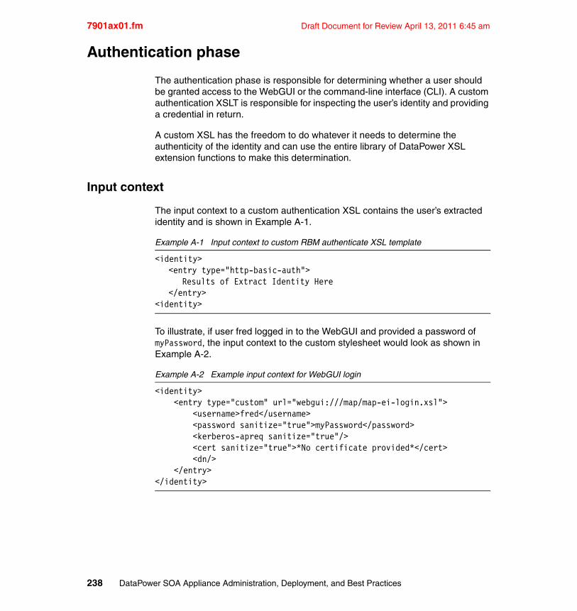
7901ax01.fm Draft Document for Review April 13, 2011 6:45 am
Authentication phase
The authentication phase is responsible for determining whether a user should be granted access to the WebGUI or the command-line interface (CLI). A custom authentication XSLT is responsible for inspecting the user’s identity and providing a credential in return.
A custom XSL has the freedom to do whatever it needs to determine the authenticity of the identity and can use the entire library of DataPower XSL extension functions to make this determination.
Input context
The input context to a custom authentication XSL contains the user’s extracted identity and is shown in Example A-1.
Example A-1 Input context to custom RBM authenticate XSL template
<identity><entry type="http-basic-auth">
Results of Extract Identity Here</entry>
<identity>
To illustrate, if user fred logged in to the WebGUI and provided a password of myPassword, the input context to the custom stylesheet would look as shown in Example A-2.
Example A-2 Example input context for WebGUI login
<identity> <entry type="custom" url="webgui:///map/map-ei-login.xsl"> <username>fred</username> <password sanitize="true">myPassword</password> <kerberos-apreq sanitize="true"/> <cert sanitize="true">*No certificate provided*</cert> <dn/> </entry></identity>
238 DataPower SOA Appliance Administration, Deployment, and Best Practices
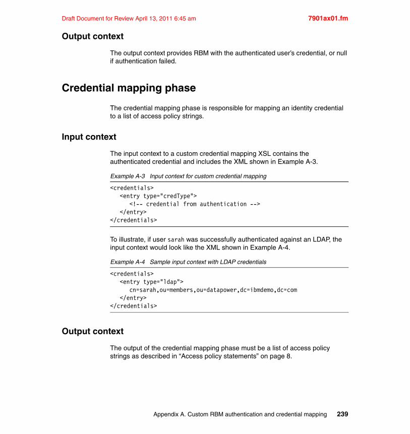
Draft Document for Review April 13, 2011 6:45 am 7901ax01.fm
Output context
The output context provides RBM with the authenticated user’s credential, or null if authentication failed.
Credential mapping phase
The credential mapping phase is responsible for mapping an identity credential to a list of access policy strings.
Input context
The input context to a custom credential mapping XSL contains the authenticated credential and includes the XML shown in Example A-3.
Example A-3 Input context for custom credential mapping
<credentials><entry type="credType">
<!-- credential from authentication --></entry>
</credentials>
To illustrate, if user sarah was successfully authenticated against an LDAP, the input context would look like the XML shown in Example A-4.
Example A-4 Sample input context with LDAP credentials
<credentials><entry type="ldap">
cn=sarah,ou=members,ou=datapower,dc=ibmdemo,dc=com</entry>
</credentials>
Output context
The output of the credential mapping phase must be a list of access policy strings as described in “Access policy statements” on page 8.
Appendix A. Custom RBM authentication and credential mapping 239
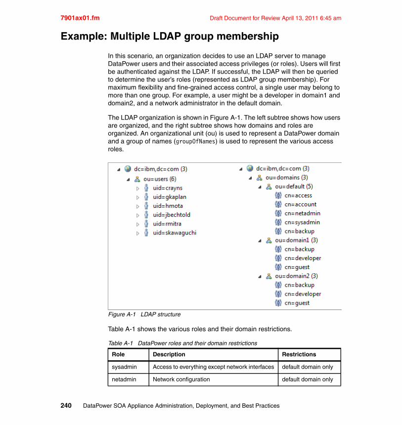
7901ax01.fm Draft Document for Review April 13, 2011 6:45 am
Example: Multiple LDAP group membership
In this scenario, an organization decides to use an LDAP server to manage DataPower users and their associated access privileges (or roles). Users will first be authenticated against the LDAP. If successful, the LDAP will then be queried to determine the user’s roles (represented as LDAP group membership). For maximum flexibility and fine-grained access control, a single user may belong to more than one group. For example, a user might be a developer in domain1 and domain2, and a network administrator in the default domain.
The LDAP organization is shown in Figure A-1. The left subtree shows how users are organized, and the right subtree shows how domains and roles are organized. An organizational unit (ou) is used to represent a DataPower domain and a group of names (groupOfNames) is used to represent the various access roles.
Figure A-1 LDAP structure
Table A-1 shows the various roles and their domain restrictions.
Table A-1 DataPower roles and their domain restrictions
Role Description Restrictions
sysadmin Access to everything except network interfaces default domain only
netadmin Network configuration default domain only
240 DataPower SOA Appliance Administration, Deployment, and Best Practices
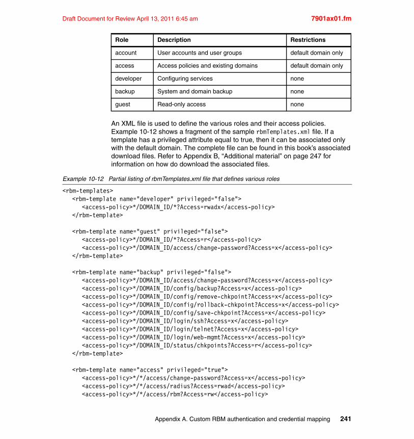
Draft Document for Review April 13, 2011 6:45 am 7901ax01.fm
An XML file is used to define the various roles and their access policies. Example 10-12 shows a fragment of the sample rbmTemplates.xml file. If a template has a privileged attribute equal to true, then it can be associated only with the default domain. The complete file can be found in this book’s associated download files. Refer to Appendix B, “Additional material” on page 247 for information on how do download the associated files.
Example 10-12 Partial listing of rbmTemplates.xml file that defines various roles
<rbm-templates><rbm-template name="developer" privileged="false">
<access-policy>*/DOMAIN_ID/*?Access=rwadx</access-policy></rbm-template>
<rbm-template name="guest" privileged="false"><access-policy>*/DOMAIN_ID/*?Access=r</access-policy><access-policy>*/DOMAIN_ID/access/change-password?Access=x</access-policy>
</rbm-template>
<rbm-template name="backup" privileged="false"><access-policy>*/DOMAIN_ID/access/change-password?Access=x</access-policy><access-policy>*/DOMAIN_ID/config/backup?Access=x</access-policy><access-policy>*/DOMAIN_ID/config/remove-chkpoint?Access=x</access-policy><access-policy>*/DOMAIN_ID/config/rollback-chkpoint?Access=x</access-policy><access-policy>*/DOMAIN_ID/config/save-chkpoint?Access=x</access-policy><access-policy>*/DOMAIN_ID/login/ssh?Access=x</access-policy><access-policy>*/DOMAIN_ID/login/telnet?Access=x</access-policy><access-policy>*/DOMAIN_ID/login/web-mgmt?Access=x</access-policy><access-policy>*/DOMAIN_ID/status/chkpoints?Access=r</access-policy>
</rbm-template>
<rbm-template name="access" privileged="true"><access-policy>*/*/access/change-password?Access=x</access-policy><access-policy>*/*/access/radius?Access=rwad</access-policy><access-policy>*/*/access/rbm?Access=rw</access-policy>
account User accounts and user groups default domain only
access Access policies and existing domains default domain only
developer Configuring services none
backup System and domain backup none
guest Read-only access none
Role Description Restrictions
Appendix A. Custom RBM authentication and credential mapping 241
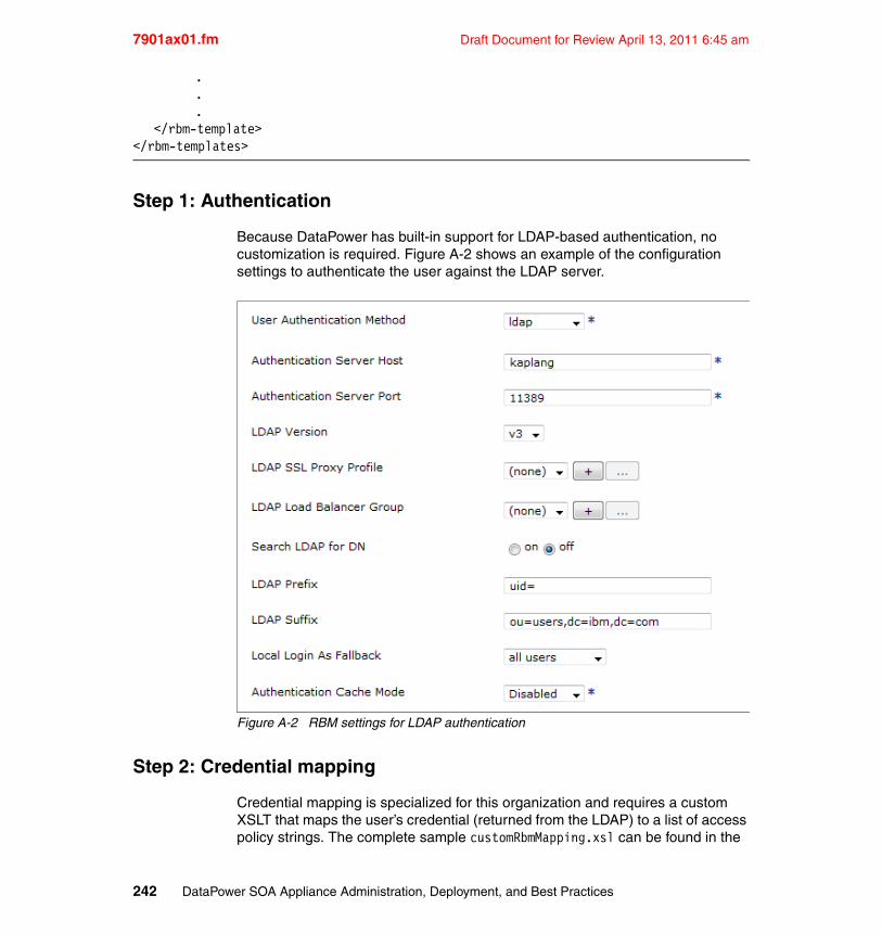
7901ax01.fm Draft Document for Review April 13, 2011 6:45 am
.
.
.</rbm-template>
</rbm-templates>
Step 1: Authentication
Because DataPower has built-in support for LDAP-based authentication, no customization is required. Figure A-2 shows an example of the configuration settings to authenticate the user against the LDAP server.
Figure A-2 RBM settings for LDAP authentication
Step 2: Credential mapping
Credential mapping is specialized for this organization and requires a custom XSLT that maps the user’s credential (returned from the LDAP) to a list of access policy strings. The complete sample customRbmMapping.xsl can be found in the
242 DataPower SOA Appliance Administration, Deployment, and Best Practices
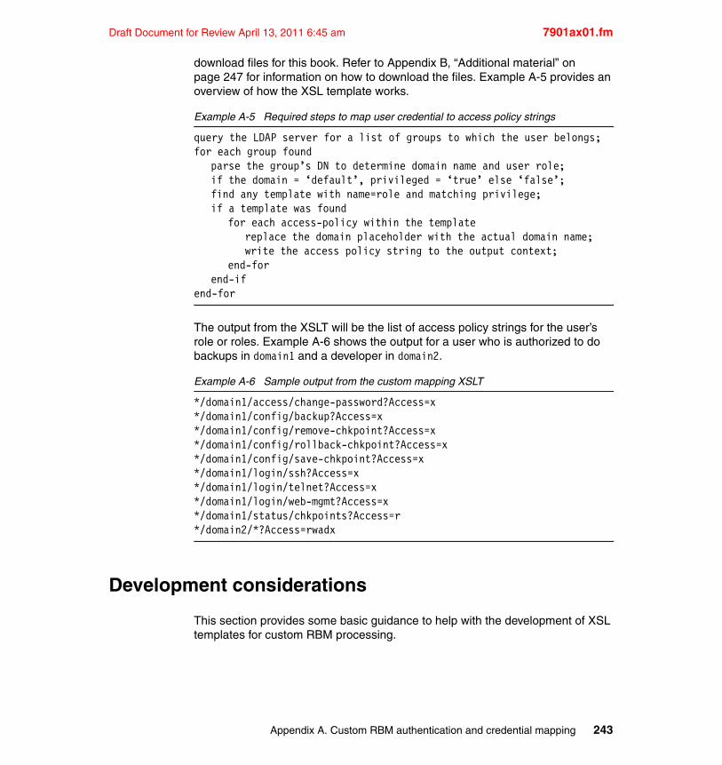
Draft Document for Review April 13, 2011 6:45 am 7901ax01.fm
download files for this book. Refer to Appendix B, “Additional material” on page 247 for information on how to download the files. Example A-5 provides an overview of how the XSL template works.
Example A-5 Required steps to map user credential to access policy strings
query the LDAP server for a list of groups to which the user belongs;for each group found
parse the group’s DN to determine domain name and user role;if the domain = ‘default’, privileged = ‘true’ else ‘false’;find any template with name=role and matching privilege;if a template was found
for each access-policy within the templatereplace the domain placeholder with the actual domain name;write the access policy string to the output context;
end-forend-if
end-for
The output from the XSLT will be the list of access policy strings for the user’s role or roles. Example A-6 shows the output for a user who is authorized to do backups in domain1 and a developer in domain2.
Example A-6 Sample output from the custom mapping XSLT
*/domain1/access/change-password?Access=x*/domain1/config/backup?Access=x*/domain1/config/remove-chkpoint?Access=x*/domain1/config/rollback-chkpoint?Access=x*/domain1/config/save-chkpoint?Access=x*/domain1/login/ssh?Access=x*/domain1/login/telnet?Access=x*/domain1/login/web-mgmt?Access=x*/domain1/status/chkpoints?Access=r*/domain2/*?Access=rwadx
Development considerations
This section provides some basic guidance to help with the development of XSL templates for custom RBM processing.
Appendix A. Custom RBM authentication and credential mapping 243
7901ax01.fm Draft Document for Review April 13, 2011 6:45 am
Use a loopback service for testingUse a stand-alone service, such as an XML Firewall or multi-protocol gateway, to develop and test XSL templates. For example, create a loopback XML Firewall that has a single transform action that executes your XSLT. This method allows you to take advantage of the transaction probe so that you can see exactly what is happening under the covers. This method is also especially useful when performing LDAP queries or off-box service calls because you can see the results of these actions. Only after the XSLT is working properly should RBM be configured to use it.
Enable local login as fallbackEnabling local login as fallback assures that you can access the appliance using local users and groups in the event that the new RBM settings do not work as planned. This fallback is critical, especially during the development and testing phase. If this login is not set, it is possible to become completely locked out of the device. Also, make sure that there is at least one user with administrative privileges that is locally defined (such as admin).
Do not enforce RBM on the CLI until changes are provenLeaving the CLI out of the mix during the development phase allows you to gain access to the appliance through the CLI to reset RBM if necessary. Enable RBM on the CLI only after the new RBM settings are tested and proven to work on the WebGUI.
Use multiple browsers during development and testingIt is convenient to use one browser as an administrator and another browser to test that configuration is working properly. This method requires different browser types for each task because sessions are generally shared within the same browser type. For example, use Firefox as the administrative browser and Internet Explorer for login testing. This method further helps to ensure that you maintain access to administrative functionality while testing.
Disable cachingMake sure to disable caching during the development and testing phases. By default, DataPower caches RBM results. After the solution is deployed, you can re-enable caching.
Using <xsl:message> for final troubleshootingAfter RBM has been set to use a custom XSL, you will lose access to the transaction probe; therefore, all troubleshooting will rely on the DataPower logs.
244 DataPower SOA Appliance Administration, Deployment, and Best Practices

Draft Document for Review April 13, 2011 6:45 am 7901ax01.fm
Enable RBM loggingOn the Troubleshooting tab, you can enable RBM logging. Doing so provides more details as to what steps are occurring during the RBM processes.
Appendix A. Custom RBM authentication and credential mapping 245

7901ax01.fm Draft Document for Review April 13, 2011 6:45 am
246 DataPower SOA Appliance Administration, Deployment, and Best Practices

Draft Document for Review April 13, 2011 6:45 am 7901addm.fm
Appendix B. Additional material
This book refers to additional material that can be downloaded from the Internet as described in the following sections.
Locating the Web material
The Web material associated with this book is available in softcopy on the Internet from the IBM Redbooks Web server. Point your Web browser at:
ftp://www.redbooks.ibm.com/redbooks/SG247901
Alternatively, you can go to the IBM Redbooks Web site at:
ibm.com/redbooks
Select the Additional materials and open the directory that corresponds with the IBM Redbooks form number, SG247901.
Using the Web material
The additional Web material that accompanies this book includes the following files:
File name Description
B
© Copyright IBM Corp. 2011. All rights reserved. 247

7901addm.fm Draft Document for Review April 13, 2011 6:45 am
createUserGroups.txt Script to create user groupscustomRbmMapping.xsl Map user credentials to access policiesrbmTemplates.xml Roles and access policies
Downloading and extracting the Web material
Create a subdirectory (folder) on your workstation, and extract the contents of the Web material .zip file into this folder.
248 DataPower SOA Appliance Administration, Deployment, and Best Practices
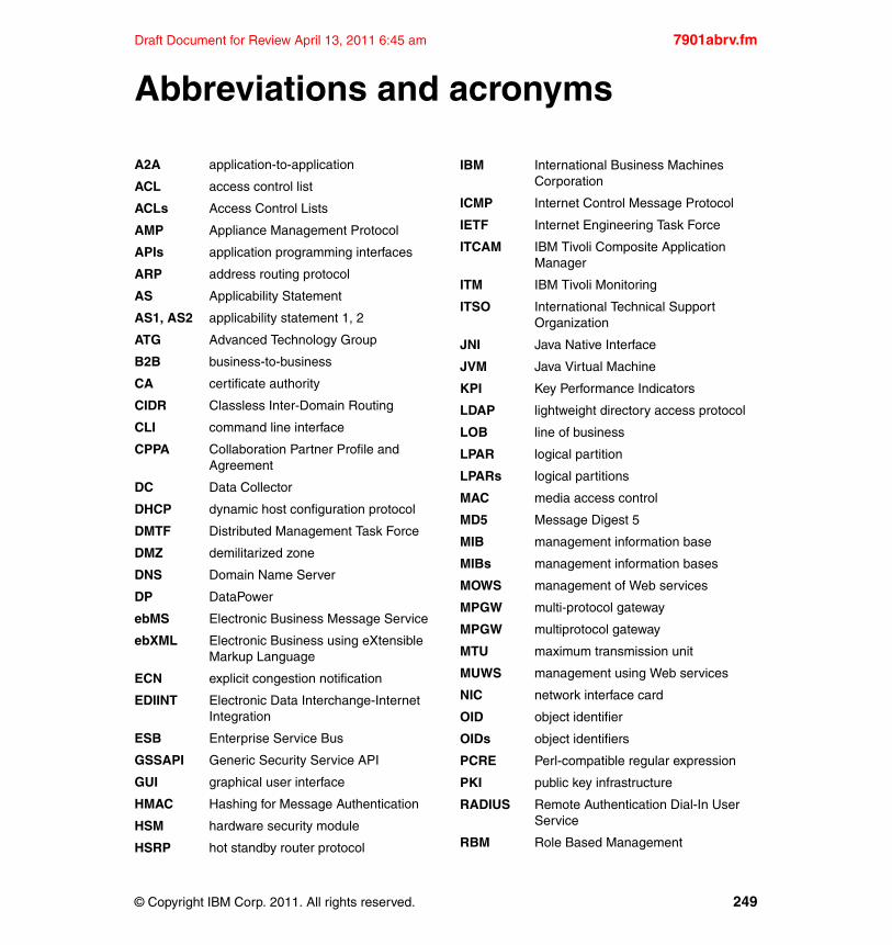
Draft Document for Review April 13, 2011 6:45 am 7901abrv.fm
acronyms
A2A application-to-application
ACL access control list
ACLs Access Control Lists
AMP Appliance Management Protocol
APIs application programming interfaces
ARP address routing protocol
AS Applicability Statement
AS1, AS2 applicability statement 1, 2
ATG Advanced Technology Group
B2B business-to-business
CA certificate authority
CIDR Classless Inter-Domain Routing
CLI command line interface
CPPA Collaboration Partner Profile and Agreement
DC Data Collector
DHCP dynamic host configuration protocol
DMTF Distributed Management Task Force
DMZ demilitarized zone
DNS Domain Name Server
DP DataPower
ebMS Electronic Business Message Service
ebXML Electronic Business using eXtensible Markup Language
ECN explicit congestion notification
EDIINT Electronic Data Interchange-Internet Integration
ESB Enterprise Service Bus
GSSAPI Generic Security Service API
GUI graphical user interface
HMAC Hashing for Message Authentication
HSM hardware security module
HSRP hot standby router protocol
Abbreviations and
© Copyright IBM Corp. 2011. All rights reserved.
IBM International Business Machines Corporation
ICMP Internet Control Message Protocol
IETF Internet Engineering Task Force
ITCAM IBM Tivoli Composite Application Manager
ITM IBM Tivoli Monitoring
ITSO International Technical Support Organization
JNI Java Native Interface
JVM Java Virtual Machine
KPI Key Performance Indicators
LDAP lightweight directory access protocol
LOB line of business
LPAR logical partition
LPARs logical partitions
MAC media access control
MD5 Message Digest 5
MIB management information base
MIBs management information bases
MOWS management of Web services
MPGW multi-protocol gateway
MPGW multiprotocol gateway
MTU maximum transmission unit
MUWS management using Web services
NIC network interface card
OID object identifier
OIDs object identifiers
PCRE Perl-compatible regular expression
PKI public key infrastructure
RADIUS Remote Authentication Dial-In User Service
RBM Role Based Management
249
7901abrv.fm Draft Document for Review April 13, 2011 6:45 am
RUP Rational Unified Process
SAF System Authorization Facility
SCM software configuration management
SDLC software development life cycle
SLA service level agreement
SLAAC Stateless Address Autoconfiguration
SLACC Stateless Address Autoconfiguration
SLM server level monitoring
SLM service level management
SNMP Simple Network Management Protocol
SNMPv1 SNMP version 1
SNMPv2 SNMP version 2
SNMPv3 SNMP version 3
SOA service oriented architecture
SOAP simple object access protocol
SOMA SOAP Configuration Management
SOMA SOAP Management Interface
SPNEGO Simple and Protected GSSAPI Negotiation Mechanism
SSH secure shell
SSL secure sockets layer
SSO single sign-on
TBSM Tivoli Business Service Management
TDW Tivoli Data Warehouse
TEC Tivoli Enterprise Console
TEMA Tivoli Enterprise Monitoring Agents
TEMS Tivoli Enterprise Monitoring Server
TEP Tivoli Enterprise Portal
TEPS Tivoli Enterprise Portal Server
TTL time-to-live
VIP virtual IP address
VLAN virtual LAN
VLANs Virtual LANs
WAMT WebSphere Appliance Management Toolkit
WebGUI web-based graphical user interface
WPA Warehouse Proxy Agent
WSDL Web Services Description Language
WSDLs Web Services Description Language
WSDM Web Services Distributed Management
WSN Web Services Navigator
WTX workstation technology extended
XMI XML Management Interface
XML eXtensible Markup Language
XSD XML Schema Definition
XSL Extensible Stylesheet Language
XSLT eXtensible Stylesheet Language Transformations
250 DataPower SOA Appliance Administration, Deployment, and Best Practices
Draft Document for Review April 13, 2011 6:45 am 7901bibl.fm
Related publications
The publications listed in this section are considered particularly suitable for a more detailed discussion of the topics covered in this book.
IBM Redbooks
The following IBM Redbooks publications provide additional information about the topic in this document. Note that some publications referenced in this list might be available in softcopy only.
� WebSphere DataPower SOA Appliance: The XML Management Interface, REDP-4446-00
� IBM WebSphere DataPower SOA Appliances Part I: Overview and Getting Started, REDP-4327-00
� IBM WebSphere DataPower SOA Appliances Part II: Authentication and Authorization, REDP-4364-00
� IBM WebSphere DataPower SOA Appliances Part III: XML Security Guide, REDP-4365-00
� IBM WebSphere DataPower SOA Appliances Part IV: Management and Governance, REDP-4366-00
You can search for, view, or download Redbooks, Redpapers, Technotes, draft publications and Additional materials, as well as order hardcopy Redbooks publications, at this Web site:
ibm.com/redbooks
Other publications
These publications are also relevant as further information sources:
� IBM WebSphere DataPower SOA Appliance Handbook, IBM Press © 2008, ISBN 9780137148196
© Copyright IBM Corp. 2011. All rights reserved. 251
7901bibl.fm Draft Document for Review April 13, 2011 6:45 am
Online resources
These Web sites are also relevant as further information sources:
� Monitoring WebSphere DataPower SOA Appliances
http://www.ibm.com/developerworks/websphere/library/techarticles/1003_rasmussen/1003_rasmussen.html
� Managing multiple DataPower Appliances with the WebSphere Appliance Management Toolkit, Part 1: Introduction to the WebSphere Appliance Management Toolkit
http://www.ibm.com/developerworks/websphere/library/techarticles/1011_burke/1011_burke.html
� Managing multiple DataPower Appliances with the WebSphere Appliance Management Toolkit, Part 2: Scripting with the WebSphere Appliance Management Toolkit
http://www.ibm.com/developerworks/websphere/library/techarticles/1102_burke/1102_burke.html
� Extending WebSphere DataPower with centralized appliance management
http://www.ibm.com/developerworks/websphere/techjournal/0809_roytman/0809_roytman.html
� Managing WebSphere DataPower SOA Appliance configurations for high availability, consistency, and control, Part 1
http://www.ibm.com/developerworks/websphere/library/techarticles/0801_rasmussen/0801_rasmussen.html
� Managing WebSphere DataPower SOA Appliance configurations for high availability, consistency, and control, Part 2: Application promotion strategies
hhttp://www.ibm.com/developerworks/websphere/library/techarticles/0904_rasmussen/0904_rasmussen.html
� WebSphere DataPower SOA Appliance performance tuning
http://www.ibm.com/developerworks/webservices/library/ws-dpperformance/index.html
� Managing WebSphere DataPower SOA Appliances via the WebSphere Application Server V7 Administrative Console
http://www.ibm.com/developerworks/websphere/library/techarticles/1003_das/1003_das.html
� WebSphere DataPower SOA Appliances developerWorks library
http://www.ibm.com/developerworks/websphere/zones/businessintegration/dp.html
252 DataPower SOA Appliance Administration, Deployment, and Best Practices
Draft Document for Review April 13, 2011 6:45 am 7901bibl.fm
� Capacity Planning for WebSphere DataPower B2B Appliance XB60
http://www-01.ibm.com/support/docview.wss?uid=swg21329746
� WebSphere DataPower V3.8.2 Information Center
http://publib.boulder.ibm.com/infocenter/wsdatap/v3r8m2/index.jsp
Help from IBM
IBM Support and downloads
ibm.com/support
IBM Global Services
ibm.com/services
Related publications 253

7901bibl.fm Draft Document for Review April 13, 2011 6:45 am
254 DataPower SOA Appliance Administration, Deployment, and Best Practices

Draft Document for Review April 13, 2011 6:45 am 7901IX.fm
Index
Aaccess control 61access control list 5access level 6
Group-defined 6Privileged 6User 6
access policies 12access policy statement 8–9
basic policy statement 10complex policy statement 11policy statement editor 11
access profile 8Active/Active high availability 180Active/Passive High Availability 175Address Mask Reply 38Address Resolution Protocol 34administering access 2Appliance Management Protocol 224–225
advantages 225disadvantages 225
appliance team 185application domain 60, 62, 67–69
benefits 60configuration file 66empty 201upgrading 201
application segregation 61application-level traffic 131app-mgmt-protocol 224Audit log 154, 156audit log 24
SOAP management interface 24authentication 3, 5–6, 22, 237–238authentication server
remote 18authenticationFailure 82authorization 5autoconfig.cfg 66automation
against 218authentication 222command line interface 230
© Copyright IBM Corp. 2011. All rights reserved.
configuration functions 216for 216management functions 216monitoring functions 216security considerations 219task 216
BB2B
Active/Active high availability 180Active/Passive High Availability 175appliance 168, 171best practices 171, 178, 181capacity planning 172Gateway Service 169integration 168metadata storage 172–173payload storage 172–173Transaction Viewer 172use cases 174Viewer 169
B2B Gateway 202backup 61basic policy statement 10Best Effort Event Logging 157best practices
B2B 171, 178, 181configuration management 214deployment 214domain 75logging 163networking 46securing access 25SNMP monitoring 124Standby Control 48
build repository 195
Ccapacity planning 62
B2B 172certificate
replacement policy 124certificate monitoring 122
255
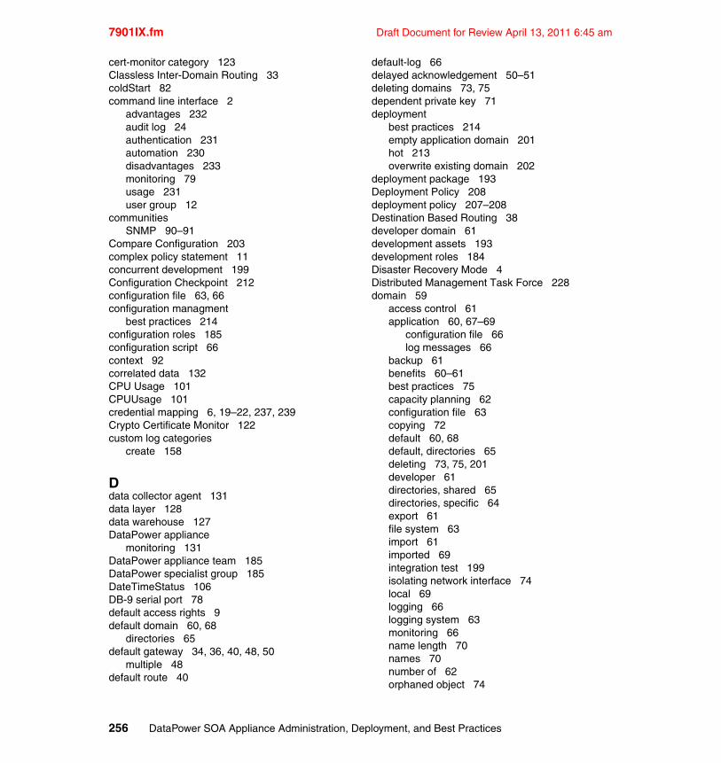
7901IX.fm Draft Document for Review April 13, 2011 6:45 am
cert-monitor category 123Classless Inter-Domain Routing 33coldStart 82command line interface 2
advantages 232audit log 24authentication 231automation 230disadvantages 233monitoring 79usage 231user group 12
communitiesSNMP 90–91
Compare Configuration 203complex policy statement 11concurrent development 199Configuration Checkpoint 212configuration file 63, 66configuration managment
best practices 214configuration roles 185configuration script 66context 92correlated data 132CPU Usage 101CPUUsage 101credential mapping 6, 19–22, 237, 239Crypto Certificate Monitor 122custom log categories
create 158
Ddata collector agent 131data layer 128data warehouse 127DataPower appliance
monitoring 131DataPower appliance team 185DataPower specialist group 185DateTimeStatus 106DB-9 serial port 78default access rights 9default domain 60, 68
directories 65default gateway 34, 36, 40, 48, 50
multiple 48default route 40
default-log 66delayed acknowledgement 50–51deleting domains 73, 75dependent private key 71deployment
best practices 214empty application domain 201hot 213overwrite existing domain 202
deployment package 193Deployment Policy 208deployment policy 207–208Destination Based Routing 38developer domain 61development assets 193development roles 184Disaster Recovery Mode 4Distributed Management Task Force 228domain 59
access control 61application 60, 67–69
configuration file 66log messages 66
backup 61benefits 60–61best practices 75capacity planning 62configuration file 63copying 72default 60, 68default, directories 65deleting 73, 75, 201developer 61directories, shared 65directories, specific 64export 61file system 63import 61imported 69integration test 199isolating network interface 74local 69logging 66logging system 63monitoring 66name length 70names 70number of 62orphaned object 74
256 DataPower SOA Appliance Administration, Deployment, and Best Practices
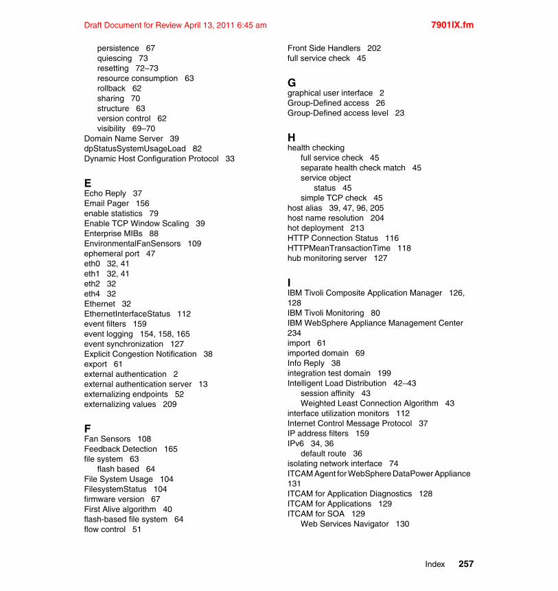
Draft Document for Review April 13, 2011 6:45 am 7901IX.fm
persistence 67quiescing 73resetting 72–73resource consumption 63rollback 62sharing 70structure 63version control 62visibility 69–70
Domain Name Server 39dpStatusSystemUsageLoad 82Dynamic Host Configuration Protocol 33
EEcho Reply 37Email Pager 156enable statistics 79Enable TCP Window Scaling 39Enterprise MIBs 88EnvironmentalFanSensors 109ephemeral port 47eth0 32, 41eth1 32, 41eth2 32eth4 32Ethernet 32EthernetInterfaceStatus 112event filters 159event logging 154, 158, 165event synchronization 127Explicit Congestion Notification 38export 61external authentication 2external authentication server 13externalizing endpoints 52externalizing values 209
FFan Sensors 108Feedback Detection 165file system 63
flash based 64File System Usage 104FilesystemStatus 104firmware version 67First Alive algorithm 40flash-based file system 64flow control 51
Front Side Handlers 202full service check 45
Ggraphical user interface 2Group-Defined access 26Group-Defined access level 23
Hhealth checking
full service check 45separate health check match 45service object
status 45simple TCP check 45
host alias 39, 47, 96, 205host name resolution 204hot deployment 213HTTP Connection Status 116HTTPMeanTransactionTime 118hub monitoring server 127
IIBM Tivoli Composite Application Manager 126, 128IBM Tivoli Monitoring 80IBM WebSphere Appliance Management Center 234import 61imported domain 69Info Reply 38integration test domain 199Intelligent Load Distribution 42–43
session affinity 43Weighted Least Connection Algorithm 43
interface utilization monitors 112Internet Control Message Protocol 37IP address filters 159IPv6 34, 36
default route 36isolating network interface 74ITCAM Agent for WebSphere DataPower Appliance 131ITCAM for Application Diagnostics 128ITCAM for Applications 129ITCAM for SOA 129
Web Services Navigator 130
Index 257

7901IX.fm Draft Document for Review April 13, 2011 6:45 am
ITCAM for SOA DataPower data collector 131ITCAM for SOA Platform 128ITCAM for Transactions 129ITCAM for Virtual Servers 129iterative life cycle 186, 198
LLDAP 18–19
group mapping 21remotely defined group 18
least connections 42life cycle stages 187
deployment 189development 189operational design 188physical installation 188solution design 188testing 189
line of business segregation 61linkDown 82linkUp 82listening address 46Load Balancer 43, 164
algorithmsleast connections 42weighted least connections 42weighted round robin 42
backend destination 41First Alive algorithm 40Group 41–42Group Object 41–42, 45health checking 44
full service check 45separate health check match 45service object
status 45simple TCP check 45
Round Robin algorithm 40local domain 69Local Login as Fallback 26local user group 7, 18
credential mapping 19local user repository 13, 15
pros and cons 13Log Action 154, 157, 160–161, 163log category 155, 162
custom 162log message storage 155
writing to a remote server 155writing to local file or cache 155
log messagesdomain 66Email Pager 156
log target 63, 154–155, 157create 158event filters 159IP address filters 159object filters 159SNMP 93
loggingasynchronous mode 163Audit logging 154benefits 157best practices 163confidentiality 165domain 66Feedback Detection 165Message process logging 154usage 157usage considerations 162
logging system 63logical segregation 61Low Latency Messaging 202
MMAC address 34management information base 80–81
structure 81management interface 50Management Of Web Services 228management roles 184–185management traffic 46Management Using Web Services 228MapCredentials 14master administrator password 4Maximum Transmission Unit 34Memory Usage 102MemoryStatus 103Message Content View 131Message Flow Pattern 131Message process log 154
event logging 154transaction logging 154
message segregation 61Meta Data document 52MgmtInterface 85
258 DataPower SOA Appliance Administration, Deployment, and Best Practices
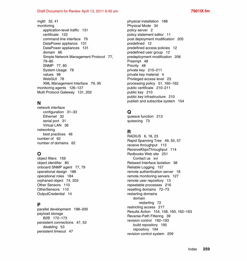
Draft Document for Review April 13, 2011 6:45 am 7901IX.fm
mgt0 32, 41monitoring
application-level traffic 131certificate 122command line interface 79DataPower appliance 131DataPower appliances 131domain 66Simple Network Management Protocol 77, 79–80SNMP 77, 80System Usage 78values 98WebGUI 78XML Management Interface 79, 95
monitoring agents 126–127Multi Protocol Gateway 131, 202
Nnetwork interface
configuration 31–33Ethernet 32serial port 31Virtual LAN 36
networkingbest practices 46
number of 62number of domains 62
Oobject filters 159object identifier 80onboard SNMP agent 77, 79operational design 188operational roles 184orphaned object 74, 203Other Sensors 110OtherSensors 110OutputCredential 14
Pparallel development 198–200payload storage
B2B 172–173persistent connections 47, 53
disabling 53persistent timeout 47
physical installation 188Physical Mode 34policy server 2policy statement editor 11post deployment modification 205predefined 12predefined access policies 12predefined user group 12predeployment modification 206Preempt 48Priority 48private key 210–211private key material 4Privileged access level 23processing policy 51, 160–162public certificate 210–211public key 210public key infrastructure 210publish and subscribe system 154
Qquiesce function 213quiescing 73
RRADIUS 6, 18, 23Rapid Spanning Tree 49, 55, 57receive throughput 113ReceiveKbpsThroughput 114Redbooks Web site 251
Contact us xviRelaxed Interface Isolation 38Reliable Logging 157remote authentication server 18remote monitoring servers 127remote user repository 13repeatable processes 216resetting domains 72–73restarting domains
domainrestarting 72
restricting access 217Results Action 154, 158, 160, 162–163Reverse-Path Filtering 39revision control 192–193
build repository 195repository 194
revision control system 209
Index 259
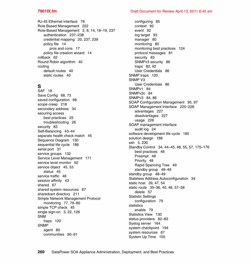
7901IX.fm Draft Document for Review April 13, 2011 6:45 am
RJ-45 Ethernet interface 78Role Based Management 222Role-Based Management 2, 8, 14, 18–19, 237
authentication 237–238credential mapping 20, 237, 239policy file 14
pros and cons 17policy file creation wizard 14
rollback 62Round Robin algorithm 40routing
default routes 40static routes 40
SSAF 18Save Config 68, 73saved configuration 68scope creep 218secondary address 34securing access
best practices 25troubleshooting 26
security 83Self-Balancing 43–44separate health check match 45Sequence Diagram 130sequential life cycle 186serial port 31service groups 132Service Level Management 171service level monitor 62service object 45, 53
status 45service traffic 46session affinity 43shared 67shared system resources 67sharedcert directory 211Simple Network Management Protocol
monitoring 77, 79–80simple TCP check 45single sign-on 3, 22, 128SNM
traps 120SNMP
agent 80communities 90–91
configuring 85context 92event 92log target 93manager 80monitoring 80monitoring best practices 124protocol messages 81security 83SNMPv3 security 86traps 82, 92User Credentials 86
SNMP traps 120SNMP V3
User Credentials 86SNMPv1 84SNMPv2c 84SNMPv3 84, 86SOAP Configuration Management 95, 97SOAP Management Interface 225–226
advantages 227disadvantages 227usage 226
SOAP management interfaceaudit log 24
software development life cycle 185solution design 188ssh 5, 230Standby Control 34, 44–45, 48, 55, 57, 175–176
best practices 48Preempt 48Priority 48Rapid Spanning Tree 49standby group 48–49
standby group 48–49Stateless Address Autoconfiguration 34static host 39, 47, 54static route 35–36, 40, 48, 57–58
delete 57Statistic Settings
configuration 79statistics
enable 79Statistics View 130status providers 82–83Syslog server 164system checkpoint 194system resources 67System Up Time 105
260 DataPower SOA Appliance Administration, Deployment, and Best Practices
Draft Document for Review April 13, 2011 6:45 am 7901IX.fm
System Usage 78, 99system-level configuration 193SystemUsageTable 100
Ttask automation 216TCP Segmentation Offload 38tcp_nodelayack 50–51Temperature Sensors 107TemperatureSensors 107Throttle Settings 104Timestamp Reply 37time-to-live 54Tivoli Composite Application Manager 80Tivoli Data Warehouse 127, 130Tivoli Enterprise Monitoring
Monitoring Agents 126Tivoli Enterprise Monitoring Server 127Tivoli Enterprise Portal 132
desktop client 127Tivoli Enterprise Portal Server 127Tivoli Management Services
components 126Tivoli Monitoring 126Tivoli Monitoring for Energy Management 129Topology View 130traceroute 35transaction logging 154, 160, 165
Log Action 154, 160–161Results Action 154, 160, 162
Transaction Rate Status 118transaction rates 83transaction times 83Transaction Viewer 172Transform Action 58transmit throughput 113TransmitKbpsThroughput 114traps
authenticationFailure 82coldStart 82linkDown 82linkUp 82SNMP 92
Uuse cases
B2B 174User access level 23
User certificate 22–23User Credentials 86user group 6, 13
CLI 12locally defined 7, 18predfined 12
user object 6user repository 6
local 13, 15remote 13
Vversion control 62Virtual LAN 36
Wwaterfall model 186Web Services Distributed Management 228
advantages 228disadvantages 228
Web Services Navigator 130Message Content View 131Message Flow Pattern 131Sequence Diagram 130Statistics View 130Topology View 130
WebGUI 78SNMP 85
web-mgmt 5WebSphere Appliance Management Center 234WebSphere Appliance Management Toolkit 228–229
advantages 230disadvantages 230usage 229
WebSphere Application Server Network Deploy-ment Appliance Manager 233WebSphere DataPower B2B Appliance 168, 170–171WebSphere Transformation Extender 171Weighted Least Connection Algorithm 43weighted least connections 42weighted round robin 42Workload Management Retrieval 43workspace segregation 61write memory 68writing to a remote server 155writing to local file or cache 155
Index 261
7901IX.fm Draft Document for Review April 13, 2011 6:45 am
WS-Addressing 228WS-BaseNotification 228WS-Management 228
advantages 228disadvantages 228
WS-Proxy 131, 202WS-ResourceProperites 228WS-Topics 228
XXML Gateway 202XML Management Interface 220–222, 224
enabling 95monitoring 79, 95
XML management interface 2XMLFirewallService 80xml-mgmt 5xml-mgmt.wsdl 226xml-mgmt.xsd 227xml-mgmt-2004.wsdl 226xml-mgmt-base.xsd 226XPath 8
262 DataPower SOA Appliance Administration, Deployment, and Best Practices

To determine the spine w
idth of a book, you divide the paper PP
I into the number of pages in the book. A
n example is a 250 page book using P
lainfield opaque 50# sm
ooth which has a P
PI of 526. D
ivided 250 by 526 which equals a spine w
idth of .4752". In this case, you would use the .5” spine. N
ow select the S
pine width for
the book and hide the others: Sp
ecial>Co
nd
ition
al Text>Sh
ow/H
ide>S
pin
eSize(-->H
ide:)>S
et . Move the changed C
onditional text settings to all files in your book by opening the book file w
ith the spine.fm still open and F
ile>Imp
ort>F
orm
ats the Conditional Text S
ettings (ON
LY!) to the book files.
Draft D
ocument for R
eview A
pril 13, 2011 6:45 am7901sp
ine.fm
263
(0.5” spine)0.475”<
->0.875”
250 <->
459 pages
DataPower SOA Appliance Adm
inistration, Deployment, and

To determine the spine w
idth of a book, you divide the paper PP
I into the number of pages in the book. A
n example is a 250 page book using P
lainfield opaque 50# sm
ooth which has a P
PI of 526. D
ivided 250 by 526 which equals a spine w
idth of .4752". In this case, you would use the .5” spine. N
ow select the S
pine width for
the book and hide the others: Sp
ecial>Co
nd
ition
al Text>Sh
ow/H
ide>S
pin
eSize(-->H
ide:)>S
et . Move the changed C
onditional text settings to all files in your book by opening the book file w
ith the spine.fm still open and F
ile>Imp
ort>F
orm
ats the Conditional Text S
ettings (ON
LY!) to the book files.
Draft D
ocument for R
eview A
pril 13, 2011 6:45 am7901sp
ine.fm
264

®
SG24-7901-00 ISBN
Draft Document for Review April 13, 2011 6:45 am
INTERNATIONAL TECHNICALSUPPORTORGANIZATION
BUILDING TECHNICALINFORMATION BASED ONPRACTICAL EXPERIENCE
IBM Redbooks are developed by the IBM International Technical Support Organization. Experts from IBM, Customers and Partners from around the world create timely technical information based on realistic scenarios. Specific recommendations are provided to help you implement IT solutions more effectively in your environment.
For more information:ibm.com/redbooks
®
DataPower SOA ApplianceAdministration, Deployment,and Best Practices
User Administration and Role-Based Management
Network Configuration, Monitoring, and Logging
Appliance and Configuration Management
This IBM Redbooks publication is part of a two volume set that focuses on operational and managerial aspects, as well as best practices for DataPower appliance deployments.
DataPower appliances provide functionality that crosses both functional and organizational boundaries which introduces unique management and operational challenges. For example, a DataPower appliance may provide network functionality such as load balancing while at the same time providing ESB capabilities such as transformation and intelligent content-based routing.
This IBM Redbooks publication provides guidance at both a general and technical level for individuals responsible for planning, installation, development, and deployment. It is not intended to be a “how-to” guide, rather to help educate about the various options and methodologies that apply to DataPower appliances. In addition, many chapters provide a list of best practices.
Back cover