Section D Industrial connectors e - Thomas & Betts …€¢ Sealed connector with quick disconnect...
54
www.tnb.ca D1 Industrial Connectors TM Table of Contents Overview ........................................................................................ D2–D11 A Series 16 A 600 VAC...................................................................D12–D13 B Series 16 A 600 VAC ................................................................. D14–D17 C Series 35 A 600 VAC ................................................................. D18–D19 D Series 10 A 600 VAC ................................................................. D20–D23 DD Series 10 A 600 VAC ............................................................... D24–D27 K Series 80A + 16 A 600 VAC ....................................................... D28–D29 V Series 16 A 600 VAC.................................................................. D30–D33 T Series 16 A 600 VAC.................................................................. D34–D35 Technical Information ................................................................... D36–D54
Transcript of Section D Industrial connectors e - Thomas & Betts …€¢ Sealed connector with quick disconnect...

w w w . t n b . c a D1
Industrial ConnectorsTM
Table of Contents
Overview ........................................................................................ D2–D11
A Series 16 A 600 VAC...................................................................D12–D13
B Series 16 A 600 VAC ................................................................. D14–D17
C Series 35 A 600 VAC ................................................................. D18–D19
D Series 10 A 600 VAC .................................................................D20–D23
DD Series 10 A 600 VAC ...............................................................D24–D27
K Series 80A + 16 A 600 VAC .......................................................D28–D29
V Series 16 A 600 VAC ..................................................................D30–D33
T Series 16 A 600 VAC ..................................................................D34–D35
Technical Information ...................................................................D36–D54

w w w . t n b . c aD2
Industrial ConnectorsTM
The FAQs about Pos-E-Kon™ Interconnects: The Most Frequently Asked Questions and Answers — for Pos-E-Kon Customers
International Standards, Worldwide Use
Why?
Rectangular Circuit Interconnections
• Best use of space for multiple contacts in heavy-duty housings
• Easy to assemble with many different insert options
• Best fit for easy access in panels, machinery and enclosures
• Sealed connector with quick disconnect handles
• Wide variety of circuit possibilities from standard items
• Solid or stranded wire in fixed or portable use
Who?
• Machine tool OEMs
• Material handling equipment OEMs
• Robotics systems OEMs and installations
• Packaging machinery OEMs and facilities
• Control panels and PLC systems
• Molding, assembly or line machinery OEMs and facilities
• Construction, mining and welding apparatus
• Carnival applications
What?
• Servo controls
• Sensing and feedback loops
• Conveyor and process controls
• Low power, DC or logic systems
• Combination power, system and other circuits
• Modular controls including fiber-optic connections
Where?
Worldwide agency approvals and applications
• DIN VDE 0627/86, 0110/02.79, and 0110-1/04.97
• IEC 60.664-1, DIN/IEC 512
• CSA Certified
• UL Recognized
• Protection classes IP44 through IP65 per IEC 529
• Component use in CE marked equipment OK per IEC Council Directive July 1999, 73/23/EEC
• Available from Thomas & Betts – Pos-E-Kon™ authorized distributors
• T&B sales representatives and agents worldwide
Overview

w w w . t n b . c a D3
Industrial ConnectorsTM
The Basic System: Build an Application
As Easy As 1. 2. 3. 4.
1. Hood• Separable housing for inserts
• Top or side conduit/wire entry
• Standard locking posts, dual or single
• Locks to Panel Base, Box Base or inline Coupler Hood
2. Base Housing (or Coupler Hood)• Surface wall-mount box base (shown)
• Panel Base for through-panel access
• Coupler Hood mating for portable use
• Single or dual “lever” locking
3. Male Insert
• Male contact carrier body
• Screw terminal contacts (pins with wire protection saddles) or crimp terminated pins
4. Female Insert• Female contact carrier
• Screw terminal contacts (sleeves with wire protection saddles) or crimp terminated sleeves
DIN Standard Configurations• Most inserts and housings are interface compatible
with other DIN standard lines. Verify physical application before selecting cross reference.
• Pos-E-Kon™ construction includes standard NPT conduit adapters for hoods and bases, with many options available. DIN standard Hoods and Bases may have “Euro Style” PG fittings (or none) included unless specially ordered.
Overview
Rectangular Circuit Interconnections
Step 1 – Maximum voltage and amperage requirements (300V or 600 V classes, 10–80 A)
Step 2 – Number of contacts or circuits needed
Step 3 – Choose wire terminations style; screw terminal or crimp contacts. Select Series from charts.
Step 4 – Base (or coupler) and hood construction/mating selection per Series (single or double levers)
HoodHood
Cable Entry Fitting
Male
Insert
Male Insert
Female
Insert
Female Insert
Cable Entry with Fitting
Base (or Coupler Hood)

w w w . t n b . c aD4
Industrial ConnectorsTM
10–16A A, B, V, T
35A C
10–80A K
10A D & DD
16A A & B
16A A & B
10A D & DD
POF D
All crimp types represented require contacts ordered separately.Each section contains hand Crimp Tool selection notes.
Pos-E-Kon™ Insert Selector ChartS – Screw Terminals
C – Crimp Contacts
F – Fiber Optic (POF)
A – Terminal Block Wiring Adapter
Overview
Screw Terminal/Insert Types (Integral Contacts)
Screw termination is used for ease of assembly plus ease of maintenance.
No tooling beyond a screwdriver and wire strippers is required.
Crimp Terminal/Insert Types (Crimp Contacts)
Crimp terminals offer solid, thermally cool vibration-resistant terminations
for OEM equipment and critical applications. Better for smaller AWG sizes
also. Crimp tools are noted in each section.
Select the # of contacts — all Blocs de connexion have separate ground contacts
Amps Volts Series 3 4 6 7 8 10 12 15 16 20 24 25 26 32 40 42 48 50-216
Select the # of contacts — all Blocs de connexion have separate ground contacts
10 50 D C, F
10 600 A S S
16 600 A S, C S, C S, C
16 600 B S, C, A S, C, A S, C, A S, C, A S, C S, C
35 600 C S S
10 600 D C, F C, F C, F C, F, A C, F, A (64)
10 600 DD C, F C, F C, F
80/16 600 K S S 4 or 8 Power (80A alone or with 8 or 16 Control (16A) Combination Blocs de connexion)
16-T 600 T S S S S High Temp (200°C)
316-V 600 V S, C S, C S, C S, C S, C S, C S, C Includes 2 Pilot Contacts

w w w . t n b . c a D5
Industrial ConnectorsTM
DIN Mounting Foot FE807TB
WAM1 Marker Tab ClipsSnap-in formed label holder tabs allow terminal identification for
B Series
Screw Terminal Inserts
• Integral screw terminal contacts provide for easy terminal wiring and fast assembly
• Standard wire protection saddles prevent cutting of strands during assembly
WAR, Right Ground Strap WAL, Left Ground StrapTerminal Block Wiring Adapters
• Allow for measuring of circuit while in operation
• Provide easy connections in panel mounting configurations
• Labels available for easy identification of circuits
• Can be mounted on DIN rails by using snap-on mounting feet
• Used in switch cabinets, panel enclosures or mounted in panel base housings — see B and D Series
Insert Strip Blank – WAM1B
Insert Strip Nos. 1–64 – WAM1N64
Insert Strip Letters A–Z – WAM1AZ
• Made of durable glass fiber-filled thermoplastic
• Contact numbers clearly marked for easy identification
• Easily installed (male or female) in either hoods or bases using captive mounting screws
Crimp Terminal Inserts
• Provide reliable connections for long-term configurations
• Contact sizes accommodate wiring from 12–20 AWG
Overview

w w w . t n b . c aD6
Industrial ConnectorsTM
Overview
Box Base Housing with single lever and spring cover. Metal spring coversavailable for B series, where noted
Panel BaseSide Cable Entry
Amps Volts Series A4 A10 A16 AA32 B6 B10 B16 B24 B32 B48
Series Application Standard Hood/Base Housing
10A 50 D D8
10A 600 A A3, A4
16A 600 A A10 A16 A32
16A 600 B B6 B10 B16 B24 B32 B48
35A 600 C C6 C12
10A 600 D D7 D15 D25 D50 D40 D64 D80 D128
10A 600 DD DD24 DD42 DD72 DD108 DD144 DD216
80/16A 600 K K4/8 K8/16
Series Application Special Series Hood/Base Housing
16A-T* 600 T T6 T10 T16 T24
16A-V** 600 V V3 V6 V10 V32
* Special high-temperature series in copper-free aluminum with special green epoxy powder coat, Viton® seals†** Special isolation design allows additional control circuit capability† Viton® is a trademark of DuPont Performance Elastomers
Hood and Base Housings• Rugged cast aluminum hoods and bases: Maximum performance in many operating conditions
• Various hood heights available: Easier assembly and wiring with low, high and standard profiles
• Corrosion-resistant finishes: Optional special materials extend life in corrosive conditions
• Locking possibilities include single locking system and double locking system
• Complete selection: Flexible product designs (see Hood/Base Cross Reference below)
• Dust covers and more: See Adapters (page D9) and Covers (page D8) or Bases with Covers available in most series (Accessories, page D50)
• Custom configurations: Multiple conduit entry/sizes and other configurations available to spec
Box BaseTop Cable Entry

w w w . t n b . c a D7
Industrial ConnectorsTM
1. Select size (# of contacts) from each Series’ section left-hand page chart (selected inserts), then look at corresponding right-hand page columns.
2. Vertical columns note single or double locking systems available (double locking usually preferable).
3. Select base housings for mounting and/or function: conduit/cable entry, thru-panel access, inline coupler or reversed locking as shown. (Note profile height options.)
4. Select side or top entry hoods as shown. (Note profile height options.)
5. Review conduit and cable entry options (standard NPT adapter sizes for each series).
Note: M Series (layout) groups interior options, followed by base selection options. Each Right-Hand Page Shows:
Hood
to
Base
Standard Bases
Standard Hoods
Reverse Locking
Hood
to
Base
Lever Hoods
Post Bases
Hood
to
Coupler
Portable Service
Coupler Hoods
Overview

w w w . t n b . c aD8
Industrial ConnectorsTM
Sub-Miniature (DB) Adapter Plates
• Connect test and diagnostic equipment to control circuits
• Panel base, box housing base or any hood installation (ribbon cable — entry hoods available)
• Industry standard sizes
• Dust covers for protection recommended
• 9, 15, 25, 37 and 50 Series
B24 Insert Mounting Adapter Plates
• Allow housing standardization for multiple applications
• B24 footprint fit to single B6, B10, B16 inserts
• Rugged thermoplastic
• Fit standard B24 Hoods and Bases
Cover Plates
• Allow custom connections for drill-and-install work
• Blank plate for expansion
• All standard Hood/Base sizes supported
Dust Covers & Hinged Covers
(thermoplastic) (thermoplastic or metal)
• Separate covers or fixed-mount hinged types
• Metal fixed-mount hinged covers for B Series bases available in select sizes
• Separate or fixed covers protect contacts when not in use or while unmated
• Refer to page D50
Overview

w w w . t n b . c a D9
Industrial ConnectorsTM
Portable Service Cord
• Sheathed industrial multi-conductor cables usage
• Options cover many installation needs
• Special constructions available for retrofit or original specification
• Hoods and Bases may be specified (in bulk volumes)
• Euro standard gland seal also available
• Refer to page D52
Standard NPT Conduit Adapters
• Euro PG to NPT thread adapters (PG male to NPT female)
• Standard on all Pos-E-Kon™ Hoods and Bases
• Available separately for MRO
• Sizes from (PG11 to 1⁄2 in.) through (PG48 to 1-1⁄2 in.) NPT
• Refer to page D52
Cord Grip Fittings
• Both NPT and PG thread styles
• Thermoplastic sealing glands in NPT, PG and ISO threads — for retrofit or original specification
• More options than shown are available (shown in grey; black also available)
• Refer to page D53
Pos-E-Kon™ Advantages
• Feature: Ergonomic thermoplastic levers for “B” Series double-lever housings B10–B24
• Benefits: Non-slip comfortable grip for easier locking and unlocking
• Feature: Laser-etched labeling for all metal housings and hot-stamped labeling on contact carrier inserts
• Benefits: Permanent marking with all data combined in external marking vs. internal label
Cable Compression Seal Fitting
Overview
Wire and Cable Entry Options
Euro Gland Seal

w w w . t n b . c aD10
Industrial ConnectorsTM
Male and Female Inserts
– same installation to any hood or base orientation
MS – Male Screw Terminal Insert (shown)
FS – Female Screw Terminal Insert (shown)
– OR –
MC – Male Crimp Insert
FC – Female Crimp Insert
>use MP – Male and FP – Female Pins
PB – Panel Base Housing
Panel face or bulkhead
mounting with rear
wiring access
BB – Box Base Housing Surface
Mount with NPT conduit
entry (1 or 2) fittings
(standard)
CH – Coupler Hood
Inline Portable Connection
Hoods
TH – Top Entry Hood with NPT fitting
SH – Side Entry Hood with NPT fitting
Wiring Entry options
• Cord or Conduit Adapter fittings
• Ribbon cable and Euro cable entry
• Housings without fittings
• Custom assemblies
Male and Female
Terminal Block Wiring
Adapters MS or FSxxxWAR/WAL
(right/left ground) options
for Panel Base installations
Overview
Easy-to-use catalogue number construction pioneered by Thomas & Betts
Locking• Single lever/Single posts or Double lever/Double posts locking
• “Reversed Locking” (levers on hoods) available
Double posts (front/back) for Double-Lever locking (single-side posts/lever also)

w w w . t n b . c a D11
Industrial ConnectorsTM
Series Features Contacts + G Page
Series Locator
A Series10A: 3, 4
16A: All others
Small, Compact Size Screw Terminal
3, 4, 10, 16, 32 D12
B Series 16A
Standard Size Screw Terminal
6, 10, 16, 24, 32, 48 D14
C Series 35A
High-Current Screw Terminal
6 or 12 D18
D Series 10A
High-Density Crimp Contacts or
Fiber Optic Contacts
7, 8, 15, 25, 40, 50, 64, 80, 128
D20
DD Series 10A
Very High-Density Crimp Contacts
24, 42, 72, 108, 144, 216 D24
K Series 16A/80A
Combo, High-Current/Std. Current Contacts à vis
16A: 8 + 480A: 16 + 8
D28
V Series 16A
Control Circuit Contacts and B Style
Contacts à vis3, 6, 20, 26, 32 D30
T Series 16A
B Style @ High-Temp 200° C
Contacts à vis6, 10, 16, 24 D34
Reference & Accessories Specs, Dimensions, Components and Fiber Optics D36
Overview

w w w . t n b . c aD12
Industrial ConnectorsTM
A Series 16 A 600 VAC
3 or 4 Contacts + Ground: 10A
10, 16 & 32 Contacts + Ground: 16A
Use small blade screwdriver to push wire entry tab in for easy contact removal
3 or 4 (600 V) 10 16 32
Install to Matching Series Hood/Base
3 or 4 + G 10 + G 16 + G 32 + G
Screw Terminal Inserts
Male – Pins20–14 AWG (0.5–2.5 mm2)
MS203A or
MS204A(16 AWG max.)
MS210A MS216A MS216A+MS232A
Female – Sleeves20–14 AWG (0.5–2.5 mm2)
FS103A orFS104A
(16 AWG max.)
FS110A FS116A
FS116A+FS132A
Crimp Tool
Cat. No.
WT611TB

w w w . t n b . c a D13
Industrial ConnectorsTM
BA
SE
HO
OD
S
BA
SE
TO H
OO
DH
OO
D T
O C
OU
PLE
R
CO
UPLE
RS
HO
OD
SB
AS
ES
BA
SE
TO H
OO
D
# of Contacts + Ground Connection
Bases — Standard Mount 3 or 4 (600 V) 10 16 32
Single Lever Double Lever Housing NPTEntry (in.)
Lever Locking Type
Single Single Single Double
Panel Base(No Cover) PB303A(P)†
PB310A PB316A PB132A
Panel Basew/Cover PB403A
PB410A PB416A
Angled,(No Cover) PB503A(P)†
Box Base(No Cover)
1 x 3/81 x 1/21 x 3/41 x 1
2 x 1/22 x 3/42 x 1
BB403APMV†BB410Amv
BB510Amv
BB416Amv
BB516Amv
BB032AmvBB832A
BB132AmvBB132A100
Box Basew/Cover
1 x 1/22 x 1/2
BB610AmvBB710Amv
BB616AmvBB716Amv
Hoods — Standard Mount *Plastic body — “A” 3-16 Series standard Hoods include gaskets; Bases and Special Hoods do not
Side Entry 1 x 3/81 x 1/21 x 3/41 x 1
SH603APmv†SH610Amv**SH710Amv**
SH616Amv**SH716Amv** SH032Amv
SH132Amv
Top Entry 1 x 3/81 x 1/21 x 3/41 x 1
TH803Apmv† TH810Amv**TH910Amv**
TH816Amv**TH916Amv** TH232Amv
TH332Amv
Coupler Hoods — Inline For inline, portable or special service connections. Coupler Hoods mate to Standard Hoods ONLY.
Top Entry 1 x 3/81 x 1/2
CH803Apmv†CH810Amv CH816Amv
Lever Hoods — Reverse Locking Lever Hoods mate to Post Bases ONLY
Side Entryw/Lever(s)
1 x 3/41 x 1
LH032AmvLH132Amv
Top Entryw/Lever(s)
1 x 3/41 x 1
LH232AmvLH332Amv
Bases — with Access Cover Post Bases accept Lever Hoods ONLY
Panel Base+Posts w/Cover
PB232A
Box Base+Posts w/Cover
1 x 3/41 x 1
2 x 3/42 x 1
BB232AmvBB232A100mv
BB332ABB332A100
** Low “L” profile may be available. Contact your Thomas & Betts sales representative.† Indicates Thermoplastique renforcé de fibre de verre construction, light grey colour (add suffix)* Indicates Thermoplastique renforcé de fibre de verre construction, black colour (add suffix); quantity purchase may be required

w w w . t n b . c aD14
Industrial ConnectorsTM
Install to Matching Series Hood/Base
6 10 16
Use small blade screwdriver to push wire entry tab in for
easy contact removal
B Series 16 A 600 VAC
6, 10 & 16 Contacts + Ground
Accessories
Wiring Adapter Insert for use with Panel Bases;
allows single access direction panel-build wiring
and easy terminal ID for service and testing
Cat. No. Description
WAM-1 Label Insert Clip
WAM1B Strip Blank
WAM1N64 Strip Nos. 1–64
WAM1AZ Strip Letters A–Z
Crimp Tool
Cat. No.
WT611TB
Screw Terminal Wiring Adapter Blocks
Screw Terminal Wiring Adapter Blocks 6 + G 10 + G 16 + G
Female Insert, Ground L.20–14 AWG (0.5–2.5 mm2)
FS106WAL FS110WAL FS116WAL
Screw Terminal Inserts
Screw Terminal Inserts 6 + G 10 + G 16 + G
Male – Pins 20–14 AWG (0.5–2.5 mm2)
MS206B
MS210B MS216B
Female – Sleeves 20–14 AWG (0.5–2.5 mm2)
FS110B FS116B
Female – Sleeves
FS106B
FS116B (1–16) + FS124B (1–24) +
20–14 AWG (0.5–6 mm2) FS132B (17–32) FS148B (25–48)

w w w . t n b . c a D15
Industrial ConnectorsTM
BA
SE
HO
OD
S
BA
SE
TO H
OO
DH
OO
D T
O C
OU
PLE
R
CO
UPLE
RS
HO
OD
SB
AS
ES
BA
SE
TO H
OO
D
# of Contacts + Ground Connection
Bases — Standard Mount 6 10 16
Single Lever Double Lever Housing NPTEntry (in.)
Lever Locking Type
Single Single Double Single Double
Panel Base(No Cover)
PB306** PB310 PB110E PB316** PB116E
Panel Basew/Cover
PB406** PB410** PB416**
Box Base(No Cover)
1 x 1/21 x 3/4 1 x 1
2 x 1/22 x 3/42 x 1
BB406mvBB406mvH075 BB406H100mv
BB506mv BB506H075mv
BB506H100
BB410mv BB410mvH075 BB410mvH100
BB510mvBB510H075mv
BB510H100
BB010emvBB010mvEH075 BB010EH100mv
BB110EmvBB110EH075mv BB110EH100mv
BB416mv* BB416H100mv
BB516mv* BB516H100mv
BB016Emv*BB016EH100mv
BB116Emv*BB116EH100mv
Box Basew/Cover
1 x 1/21 x 3/41 x 1
2 x 1/22 x 3/42 x 1
BB606mv** BB606H075mv**
BB606H100** BB706mv**
BB706H075** BB706H100**
BB610mv**BB610H075mv** BB610H100mv**
BB710mv**BB710H075mv** BB710H100mv**
BB616mv* **BB616mvH100**
BB716mv* **BB716H100mv**
CAPOTS — Standard Mount Plastic body — “B” 3-16 Series Standard CAPOTS include gaskets; EMBASES and Special CAPOTS do not
Side Entry1 x 1/21 x 3/4 1 x 1
SH606MVSH606H075mv SH606H100mv
SH610mvSH610H075mv SH610H100mv
SH010mvSH010H075mv SH010H100mv
SH616mv† SH716Hmv†
SH016mv†SH116Hmv
Top Entry1 x 1/21 x 3/41 x 1
TH806mv TH806H075mv TH806H100mv
TH810mv TH810H075mvTH810H100mv
TH210mvTH210H075mv TH210H100mv
TH816mv† TH816H100mv
TH216mv†TH316Hmv
Coupler Hoods — Inline For inline, portable or special service connections. Coupler Hoods mate to Standard Hoods ONLY.
Top Entry1 x 1/21 x 3/41 x 1
CH806Hmv CH806H075mv CH806H100mv
CH810EmvCH810H075mv CH810H100mv
CH610ECH610EH075mvCH610EH100mv
CH816Hmv CH916Hmv
CH616EHmvCH716EHmv
Lever Hoods — Reverse Locking Lever Hoods mate to Post Bases ONLY
Side Entryw/Lever(s)
1 x 1/21 x 3/41 x 3/4
LH010EmvLH010EH075mvLH010EH100mv
LH016Emv*LH116EHmv
Top Entryw/Lever(s)
1 x 1/21 x 3/41 x 1
LH210EmvLH210EH075mvLH210EH100mv
LH216E*LH316EHmv
Bases — with Access Cover Post Bases accept Lever Hoods ONLY
Panel Base+Posts w/Cover
PB210** PB216**
Box Base+Posts w/Cover
1 x 1/21 x 3/41 x 1
2 x 1/22 x 3/42 x 1
BB210mv**BB210H075mv**BB210H100mv**
BB310mv**BB310H075mv**BB310H100mv**
BB216mv* **BB216H100mv**
BB316mv**BB316H100mv**
* High “H” profile may be available. Contact your Thomas & Betts sales representative. ** Metal “M” cover may be available. Contact your Thomas & Betts sales representative. † High “H” and Low “L” profile may be available. Contact your Thomas & Betts sales representative.

w w w . t n b . c aD16
Industrial ConnectorsTM
Accessories
Wiring Adapter Insert for use with Panel Bases;
allows single access direction panel-build wiring
and easy terminal ID for service and testing
Cat. No. Description
WAM-1 Label Insert Clip
WAM1B Strip Blank
WAM1N64 Strip Nos. 1–64
WAM1AZ Strip Letters A–Z
Screw Terminal Inserts
Screw Terminal Inserts 24 + G 32 + G 48 + G
Male – Pins
MS224B
MS216B (1–16) MS224B (1–24)
20–14 AWG (0.5–6 mm2) + MS232B (17–32) + MS248B (25–48)
Female – Sleeves
FS124B
FS116B (1–16) + FS124B (1–24) +
20–14 AWG (0.5–6 mm2) FS132B (17–32) FS148B (25–48)
Screw Terminal Wiring Adapter Blocks
Screw Terminal Inserts 24 + G
Female Insert, Ground L.20–14 AWG (0.5–2.5 mm2)
FS124WAL
Crimp Terminal Inserts
Crimp Terminal Inserts 24 + G 32 + G 48 + G
Male Insert MC424B
(1–16) MC416B (1–24) MC424B
(17–32) MC432B (25–48) MC448B
Female Insert FC324B
(1–16) FC316B (1–24) FC324B
(17–32) FC332B (25–48) FC348B
Install to Matching Series Hood/Base
24 32 48
B Series 16 A 600 VAC
24, 32 & 48 Contacts + Ground
Use small blade screwdriver to push wire entry tab in for
easy contact removal
Crimp Tool
Cat. No.
WT611TB

w w w . t n b . c a D17
Industrial ConnectorsTM
BA
SE
HO
OD
S
BA
SE
TO H
OO
DH
OO
D T
O C
OU
PLE
R
CO
UPLE
RS
HO
OD
SB
AS
ES
BA
SE
TO H
OO
D
# of Contacts + Ground Connection
Bases — Standard Mount 24 32 48
Single Lever Double Lever Housing NPTEntry (in.)
Lever Locking Type
Single Double Double Single
Panel Base(No Cover)
PB324 PB124E PB132 PB348
Panel Basew/Cover
PB424† PB448
Box Base(No Cover)
1 x 3/41 x 1
2 x 3/42 x 1
BB424mv*BB424H100mv
BB524mv*BB524H100mv
BB024emv*BB024EH100mv
BB124emv*BB124EH100mv
BB032mv
BB132mv
BB448mv
BB548mv
Box Basew/Cover
1 x 3/41 x 1
2 x 3/42 x 1
BB624mv*†
BB624H100mv†
BB724mv*†
BB724H100mv†
BB648mv
BB748mv
Hoods— Standard Mount Plastic body— “A” 3-16 Series Standard Hoods include gaskets; Bases and Special Hoods do not
Side Entry1 x 3/41 x 1
1 x 1-1/4
SH624mv**SH724mv**
SH024mv**SH124mv**
SH032mvSH132mv
SH132125mvSH648mvSH748mv
Top Entry
1 x 3/41 x 1
1 x 1-1/4Ribbon Cbl
TH824mv**TH924mv**
TH224mv**TH324mv**
TH424RCmv
TH232mvTH332mv
TH332125mvTH848mvTH948mv
Coupler Hoods — Inline For inline, portable or special service connections. Coupler Hoods mate to Standard Hoods ONLY.
Top Entry1 x 3/41 x 1
Ribbon Cbl
CH824mvCH924mv
CH624EmvCH724Emv
CH724ERCmv
CH632mvCH732mv
Lever Hoods — Reverse Locking Lever Hoods mate to Post Bases ONLY
Side Entryw/Lever(s)
1 x 3/41 x 1
LH024EmvLH124Emv
Top Entryw/Lever(s)
1 x 3/41 x 1
LH224ELH324Emv
Bases — with Access Cover Post Bases accept Lever Hoods ONLY
Panel Base+Posts w/Cover
PB224†
Box Base+Posts w/Cover
1 x 3/41 x 1
2 x 3/42 x 1
BB224mv*†
BB224H100mvBB324mv*†
BB324H100mv
* High “H” profile may be available. Contact your Thomas & Betts sales representative.** Low “L” profile may be available. Contact your Thomas & Betts sales representative.† Metal “M” cover may be available. Contact your Thomas & Betts sales representative.
w w w . t n b . c aD18
Industrial ConnectorsTM
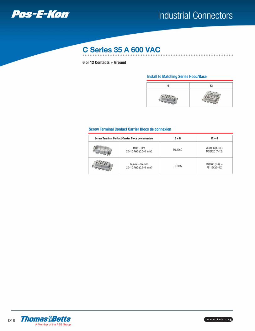
C Series 35 A 600 VAC
6 or 12 Contacts + Ground
Screw Terminal Contact Carrier Blocs de connexion
Screw Terminal Contact Carrier Blocs de connexion 6 + G 12 + G
Male – Pins20–10 AWG (0.5–6 mm2)
MS206CMS206C (1–6) +MS212C (7–12)
Female – Sleeves20–10 AWG (0.5–6 mm2)
FS106CFS106C (1–6) +FS112C (7–12)
Install to Matching Series Hood/Base
6 12

w w w . t n b . c a D19
Industrial ConnectorsTM
BA
SE
HO
OD
S
BA
SE
TO H
OO
DH
OO
D T
O C
OU
PLE
R
CO
UPLE
RS
HO
OD
SB
AS
ES
BA
SE
TO H
OO
D
# of Contacts + Ground Connection
Bases — Standard Mount 6 12
Single Lever Double Lever Housing NPTEntry (in.)
Lever Locking Type
Single Double Double
Panel Base (No Cover)
PB316 PB116E PB132
Panel Base w/Cover
PB416
Box Base(No Cover)
1 x 3/41 x 1
2 x 3/42 x 1
BB416mv*BB416H100mv
BB516mv*BB516H100mv
BB016Emv*BB016EH100mv
BB116Emv*BB116EH100mv
BB032mv
BB132mv
Box Base w/Cover
1 x 1/21 x 1
2 x 1/22 x 1
BB616mv*†BB616H100mv†
BB716mv*†BB716H100mv†
Hoods — Standard Mount
Side Entry1 x 3/41 x 1
1x 1-1/4
SH616mv‡ SH716Hmv
SH016mv‡SH116Hmv
SH032mvSH132mv
SH132125mv
Top Entry1 x 3/41 x 1
1x 1-1/4
TH816mv‡ TH816H100mv
TH216mv‡ TH316Hmv
TH232mvTH332mv
TH332125mv
Coupler Hoods — Inline For inline, portable or special service connections. Coupler Hoods mate to Standard Hoods ONLY.
Top Entry1 x 3/41 x 1
CH816Hmv CH916Hmv
CH616EHmv CH716EHmv
CH632mvCH732mv
Lever Hoods — Reverse Locking Lever Hoods mate to Post Bases ONLY
Side Entryw/Lever(s)
1 x 3/41 x 1
LH016Emv* LH116EHmv
Top Entryw/Lever(s)
1 x 3/41 x 1
LH216E*LH316EHmv
Bases — with Access Cover Post Bases accept Lever Hoods ONLY
Panel Basew/Posts + Cover
PB216†
Box Basew/Posts + Cover
1 x 3/41 x 1
2 x 3/42 x 1
BB216mv*†
BB216H100mv†
BB316mv*†
BB316H100mv†
* High “H” profile may be available. Contact your Thomas & Betts sales representative.** Low “L” profile may be available. Contact your Thomas & Betts sales representative.† Metal “M” cover may be available. Contact your Thomas & Betts sales representative.‡ High “H” and Low “L” profile may be available. Contact your Thomas & Betts sales representative.

w w w . t n b . c aD20
Industrial ConnectorsTM
Crimp Terminal Inserts
Crimp Terminal Inserts 7 or 8 + G 15 + G 25 + G 40 + G
Male Insert(Order contacts below)
MC407D orMC408D
MC415D MC425D MC440D
Female Insert(Order contacts below)
FC307D orFC308D
FC315D FC325D FC340D
Contacts Sold Separately
Screw Terminal Wiring Adapter Blocks
Screw Terminal Wiring Adapter Blocks — — — 40 + G
Male Insert, Ground L. 26–16 AWG (0.2–1.5mm2)
— — — MS440WAL
Female Insert, Ground L.26–16 AWG (0.2–1.5mm2)
— — — FS340WAL
D Series 10 A 600 VAC
7 or 8, 15, 25 & 40 Contacts + Ground
Accessories
Wiring Adapter Insert for use with Panel Bases;
allows single access direction panel-build wiring
and easy terminal ID for service and testing
Cat. No. Description
WAM-1 Label Insert Clip
WAM1B Strip Blank
WAM1N64 Strip Nos. 1–64
WAM1AZ Strip Letters A–Z
Crimp Tool
Cat. No.
WT80
Extraction Tool
Cat. No.
RT614
See page D54 for POF
installation and tools info.
Install to Matching Series Hood/Base
7 or 8 15 25 40
Contacts Selection Chart
Crimp Contacts Wire AWG (mm2) Identification
22+ AWG (0.14–.37) 1
20 AWG 0 (0.5) 2
18 AWG (0.75–1) 3
16 AWG (01.5) 4
14 AWG (2.5) 5
I.D.
For Optic Contacts
Crimp Contacts Wire AWG (mm2) Identification
18 AWG (0.75–1) 3
Female Male
FP18SD MP18SD
For All Crimp Terminal “D” Inserts:
Female Male
FP22SD MP22SD
FP20SD MP20SD
FP18SD MP18SD
FP16SD MP16SD
FP14SD MP14SD

w w w . t n b . c a D21
Industrial ConnectorsTM
BA
SE
HO
OD
S
BA
SE
TO H
OO
DH
OO
D T
O C
OU
PLE
R
CO
UPLE
RS
HO
OD
SB
AS
ES
BA
SE
TO H
OO
D
# of Contacts + Ground Connection
Bases — Standard Mount 7 ou 8 15 25 40
Single Lever Double Lever HousingNPT
Entry(in.)
Lever Locking Type
Single Single Double Single Double
Panel Base(No Cover)
PB303A(P)** PB310A PB316 PB116E
Panel Basew/Cover
PB403A PB410A PB316A PB416
Angled,(No Cover)
PB503A(P)** PB416A
Box Base(No Cover)
1 x 3/81 x 1/22 x 1/21 x 3/41 x 1
2 x 3/42 x 1
BB403Apmv**BB410Amv BB510Amv
BB416AmvBB516Amv
BB416MV* BB416H100mv
BB516MV* BB516H100mv
BB016Emv*BB016EH100mv
BB116Emv*BB116EH100mv
Box Basew/Cover
1 x 1/21 x 3/41 x 1
2 x 1/22 x 3/42 x 1
BB610Amv BB710Amv
BB616AmvBB716Amv
BB616MV*†BB616H100mv†
BB716mv*†BB716H100mv†
Hoods— Standard Mount Plastic body— “A” 3-16 Series Standard Hoods include gaskets; Bases and Special Hoods do not
Side Entry
1 x 3/81 x 1/21 x 3/41 x 1
SH603apmv**SH610Amv SH710Amv
SH616AmvSH716Amv SH616MV‡
SH716Hmv‡ SH016mv‡SH116Hmv
Top Entry
1 x 3/81 x 1/21 x 3/41 x 1
TH803Apmv**TH810Amv TH910Amv
TH816AmvTH916Amv TH816mv‡
TH816H100mv TH216mv‡TH316Hmv
Coupler Hoods — Inline For inline, portable or special service connections. Coupler Hoods mate to Standard Hoods ONLY.
Top Entry
1 x 3/81 x 1/2 1 x 3/41 x 1
CH803Apmv**CH810Amv CH816Amv
CH816Hmv CH916Hmv
CH616EHmvCH716EHmv
Lever Hoods — Reverse Locking Lever Hoods mate to Post Bases ONLY
Side Entryw/Lever(s)
1 x 3/41 x 1
LH016Emv*LH116EHmv
Top Entry w/Lever(s)
1 x 3/41 x 1
LH216E*LH316EHmv
Bases — with Access Cover Post Bases accept Lever Hoods ONLY
Panel Base+Posts w/Cover
PB216†
Box Base+Posts w/Cover
1 x 3/41 x 1
2 x 3/42 x 1
BB216mv*†BB216H100mv†
BB316mv*†BB316H100mv†
* High “H” profile may be available. Contact your Thomas & Betts sales representative.** Low “L” profile may be available. Contact your Thomas & Betts sales representative.† Metal “M” cover may be available. Contact your Thomas & Betts sales representative.‡ High “H” and Low “L” profile may be available. Contact your Thomas & Betts sales representative.
w w w . t n b . c aD22
Industrial ConnectorsTM
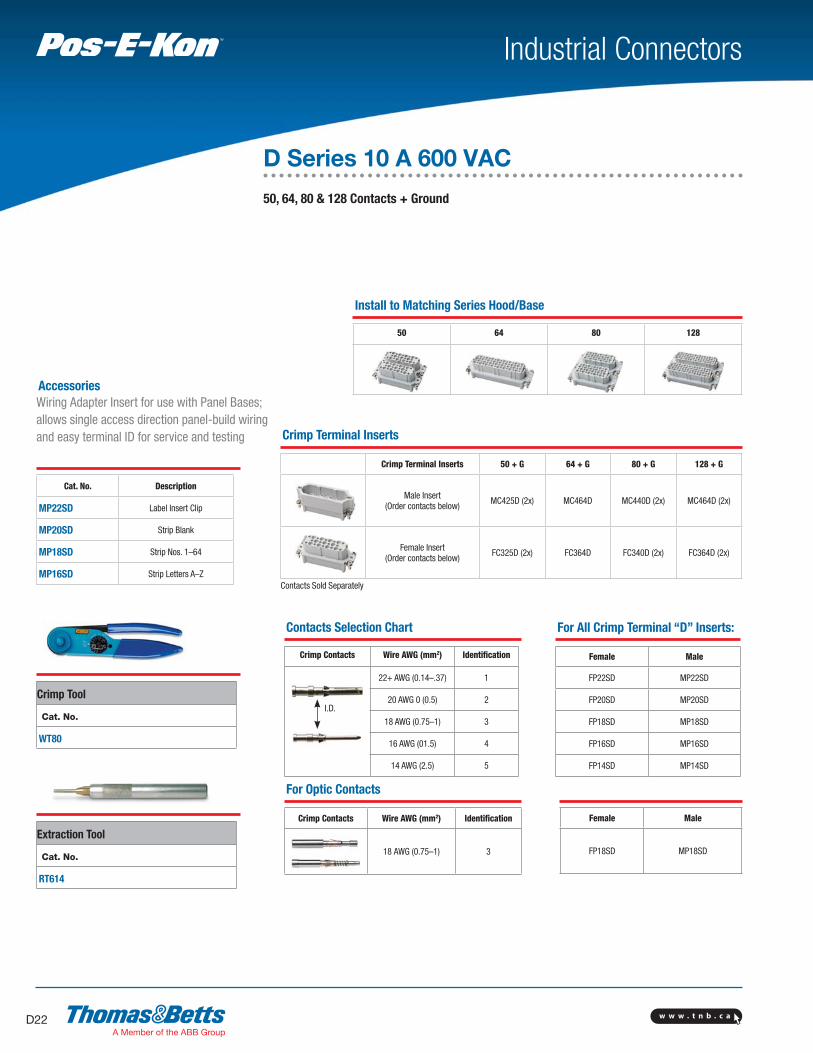
D Series 10 A 600 VAC
50, 64, 80 & 128 Contacts + Ground
Accessories
Wiring Adapter Insert for use with Panel Bases;
allows single access direction panel-build wiring
and easy terminal ID for service and testing
Cat. No. Description
MP22SD Label Insert Clip
MP20SD Strip Blank
MP18SD Strip Nos. 1–64
MP16SD Strip Letters A–Z
Crimp Tool
Cat. No.
WT80
Extraction Tool
Cat. No.
RT614
Install to Matching Series Hood/Base
50 64 80 128
Crimp Terminal Inserts
Crimp Terminal Inserts 50 + G 64 + G 80 + G 128 + G
Male Insert(Order contacts below)
MC425D (2x) MC464D MC440D (2x) MC464D (2x)
Female Insert(Order contacts below)
FC325D (2x) FC364D FC340D (2x) FC364D (2x)
Contacts Sold Separately
Contacts Selection Chart
Crimp Contacts Wire AWG (mm2) Identification
22+ AWG (0.14–.37) 1
20 AWG 0 (0.5) 2
18 AWG (0.75–1) 3
16 AWG (01.5) 4
14 AWG (2.5) 5
I.D.
For Optic Contacts
Crimp Contacts Wire AWG (mm2) Identification
18 AWG (0.75–1) 3
Female Male
FP18SD MP18SD
For All Crimp Terminal “D” Inserts:
Female Male
FP22SD MP22SD
FP20SD MP20SD
FP18SD MP18SD
FP16SD MP16SD
FP14SD MP14SD

w w w . t n b . c a D23
Industrial ConnectorsTM
* High “H” profile may be available. Contact your Thomas & Betts sales representative.
** Low “L” profile may be available. Contact your Thomas & Betts sales representative.† Metal “M” cover may be available. Contact your Thomas & Betts sales representative.‡ High “H” and Low “L” profile may be available. Contact your Thomas & Betts sales representative.
BA
SE
HO
OD
S
BA
SE
TO H
OO
DH
OO
D T
O C
OU
PLE
R
CO
UPLE
RS
HO
OD
SB
AS
ES
BA
SE
TO H
OO
D
# of Contacts + Ground Connection
Bases — Standard Mount 50 64 80 128
Single Lever Double Lever Housing NPTEntry (in.)
Lever Locking Type
Double Single Double Double Single
Panel Base(No Cover)
PB132A PB324 PB124E PB132 PB348
Panel Basew/Cover
PB424
Box Base(No Cover)
1 x 3/41 x 1
2 x 3/4 2 x 1
BB032AmvBB832AmvBB132AmvBB132A100
BB424mv*BB424H100mv
BB524mv*BB524H100mv
BB024emv*BB024EH100mv
BB124emv*BB124EH100mv
BB032mv
BB132mv
BB448mv
BB548mv
Box Basew/Cover
1 x 3/4 1 x 1
2 x 3/4 2 x 1
BB642*†
BB642H100†
BB724mv*†
BB724H100mv†
BB648mv
BB748mv
Hoods— Standard Mount Plastic body— “A” 3-16 Series Standard Hoods include gaskets; Bases and Special Hoods do not
Side Entry 1 x 3/41 x 1
1 x 1-1/4
SH032AmvSH132Amv
SH624mv**SH724mv**
SH024mv**SH124mv**
SH032mvSH132mv
SH648mvSH748mv
Top Entry 1 x 3/4 1 x 1
1 x 1-1/4 Ribbon Cbl
TH232AmvTH332Amv
TH824mv**TH924mv
TH624RC
TH224mv**TH324mv
TH424RC
TH232mvTH332mv
TH848mvTH948
Coupler Hoods — Inline For inline, portable or special service connections. Coupler Hoods mate to Standard Hoods ONLY.
Top Entry 1 x 3/41 x 1
Ribbon Cbl
CH824mvCH924mv
CH624EmvCH724Emv
CH724ERCMV
CH632mvCH732mv
Lever Hoods — Reverse Locking Lever Hoods mate to Post Bases ONLY
Side Entryw/Lever(s)
1 x 3/41 x 1
LH032AmvLH132Amv
LH024EmvLH124Emv
Top Entryw/Lever(s)
1 x 3/41 x 1
LH232AmvLH332Amv
LH224ELH324Emv
Bases — with Access Cover Post Bases accept Lever Hoods ONLY
Panel Base+Posts w/Cover
PB232A PB224†
Box Base+Posts w/Cover
1 x 3/41 x 1
2 x 3/42 x 1
BB232AmvBB232A100mv
BB332ABB332A100
BB224mv*†
BB224H100mvBB324mv*†
BB324H100mv

w w w . t n b . c aD24
Industrial ConnectorsTM
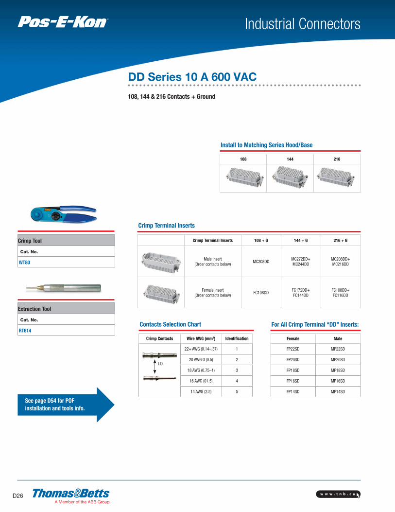
Crimp Terminal Inserts
Screw Terminal Inserts 24 + G 42 + G 72 + G
Male Insert(Order contacts below)
MC224DD MC242DD MC272DD
Female Insert(Order contacts below)
FC124DD FC142DD FC172DD
Install to Matching Series Hood/Base
24 42 72
DD Series 10 A 600 VAC
24, 42 & 72 Contacts + Ground
See page D54 for POF
installation and tools info.
Crimp Tool
Cat. No.
WT80
Extraction Tool
Cat. No.
RT614Contacts Selection Chart
Crimp Contacts Wire AWG (mm2) Identification
22+ AWG (0.14–.37) 1
20 AWG 0 (0.5) 2
18 AWG (0.75–1) 3
16 AWG (01.5) 4
14 AWG (2.5) 5
I.D.
For All Crimp Terminal “DD” Inserts:
Female Male
FP22SD MP22SD
FP20SD MP20SD
FP18SD MP18SD
FP16SD MP16SD
FP14SD MP14SD

w w w . t n b . c a D25
Industrial ConnectorsTM
* High “H” profile may be available. Contact your Thomas & Betts sales representative.
** Low “L” profile may be available. Contact your Thomas & Betts sales representative.† Metal “M” cover may be available. Contact your Thomas & Betts sales representative.‡ High “H” and Low “L” profile may be available. Contact your Thomas & Betts sales representative.
BA
SE
HO
OD
S
BA
SE
TO H
OO
DH
OO
D T
O C
OU
PLE
R
CO
UPLE
RS
HO
OD
SB
AS
ES
BA
SE
TO H
OO
D
# of Contacts + Ground Connection
Bases — Standard Mount 24 42 72
Single Lever Double Lever Housing NPTEntry (in.)
Lever Locking Type
Single Single Double Single Double
Panel Base (No Cover) PB306** PB310** PB110E PB316 PB116E
Panel Base w/Cover PB406** PB410** PB416
Box Base(No Cover)
1 x 1/21 x 3/41 x 1
2 x 1/22 x 3/4 2 x 1
BB406mvBB406mvH075BB406H100mv
BB506mvBB506H075mv
BB506H100
BB410mvBB410H075mvBB410H100mv
BB510mvBB510H075mv
BB510H100
BB010emvBB010EH075mvBB010EH100mv
BB110EmvBB110EH075mvBB110EH100mv
BB416mv*BB416H100mv
BB516mv*BB516H100mv
BB016Emv*BB016EH100mv
BB116Emv*BB116EH100mv
Box Base
1 x 1/2 1 x 3/4 1 x 1
2 x 1/2 2 x 3/4 2 x 1
BB606mv**BB606H075mv**
BB606H100**BB706mv**
BB706H075**BB706H100**
BB610mv**BB610H075mv**BB610H100mv**
BB710mv**BB710H075mv**BB710H100mv**
BB616mv* **BB616H100mv**
BB716mv* **BB716H100mv**
Hoods — Standard Mount
Side Entry1 x 1/21 x 3/41 x 1
SH606mvSH606H075mvSH606H100mv
SH610mvSH610H075mvSH610H100mv
SH010mvSH010H075mvSH010H100mv
SH616mv†
SH716Hmv†
SH016mv†
SH116Hmv
Top Entry1 x 1/21 x 3/41 x 1
TH806mvTH806H075mvTH806H100mv
TH810mvTH810H075mvTH810H100mv
TH210mvTH210H075mvTH210H100mv
TH816mv†
TH816H100mvTH216mv†
TH316Hmv
Coupler Hoods — Inline For inline, portable or special service connections. Coupler Hoods mate to Standard Hoods ONLY.
Top Entry w/ Leveler(s)
1 x 1/21 x 3/41 x 1
CH806CH806H075mvCH806H100mv
CH810CH810H075mvCH810H100mv
CH610ECH610EH075mvCH610EH100mv
CH816HmvCH916Hmv
CH616EHmvCH716EHmv
Lever Hoods — Reversed Locking Lever Hoods mate to Post Bases ONLY
Side Entryw/Lever(s)
1 x 1/21 x 3/41 x 1
LH010EmvLH010EH075mvLH010EH100mv
LH016Emv*LH116EHmv
Top Entryw/Lever(s)
1 x 1/21 x 3/41 x 1
LH210EmvLH210EH075mvLH210EH100mv
LH216E*LH316EHmv
Bases — with Access Cover Post Bases accept Lever Hoods ONLY
Panel +Posts w/Cover
PB210** PB216**
Box +Posts w/Cover
1 x 1/21 x 3/41 x 1
2 x 1/22 x 3/42 x 1
BB210mv**BB210H075mv**BB210H100mv**
BB310mv**BB310H075mv**BB310H100mv**
BB216mv* **BB216H100mv**
BB316mv* **BB316H100mv**
w w w . t n b . c aD26
Industrial ConnectorsTM
Crimp Terminal Inserts
Crimp Terminal Inserts 108 + G 144 + G 216 + G
Male Insert(Order contacts below)
MC208DDMC272DD+MC244DD
MC208DD+MC216DD
Female Insert(Order contacts below)
FC108DDFC172DD+FC144DD
FC108DD+FC116DD
Install to Matching Series Hood/Base
108 144 216
DD Series 10 A 600 VAC
108, 144 & 216 Contacts + Ground
See page D54 for POF
installation and tools info.
Crimp Tool
Cat. No.
WT80
Extraction Tool
Cat. No.
RT614Contacts Selection Chart
Crimp Contacts Wire AWG (mm2) Identification
22+ AWG (0.14–.37) 1
20 AWG 0 (0.5) 2
18 AWG (0.75–1) 3
16 AWG (01.5) 4
14 AWG (2.5) 5
I.D.
For All Crimp Terminal “DD” Inserts:
Female Male
FP22SD MP22SD
FP20SD MP20SD
FP18SD MP18SD
FP16SD MP16SD
FP14SD MP14SD

w w w . t n b . c a D27
Industrial ConnectorsTM
* High “H” profile may be available. Contact your Thomas & Betts sales representative.** Low “L” profile may be available. Contact your Thomas & Betts sales representative.† Metal “M” cover may be available. Contact your Thomas & Betts sales representative.
BA
SE
HO
OD
S
BA
SE
TO H
OO
DH
OO
D T
O C
OU
PLE
R
CO
UPLE
RS
HO
OD
SB
AS
ES
BA
SE
TO H
OO
D
# of Contacts + Ground Connection
Bases — Standard Mount 108 144 216
Single Lever Double Lever Housing NPTEntry (in.)
Lever Locking Type
Single Double Double Single
Panel Base(No Cover)
PB324 PB124E PB132 PB348
Panel Basew/Cover
PB424† PB448
Box Base(No Cover)
1 x 3/41 x 1
2 x 3/4 2 x 1
BB424mv*BB424H100mv
BB524mv*BB524H100mv
BB024EMV*BB024EH100mv
BB124emv*BB124EH100mv
BB032mv
BB132mv
BB448mv
BB548mv
Box Basew/Cover
1 x 3/41 x 1
2 x 3/42 x 1
BB624MV*†
BB624H100mv†
BB724mv*†
BB724H100mv†
BB648mv
BB748mv
Hoods— Standard Mount
Side Entry1 x 3/41 x 1
1 x 1-1/4
SH624mv**SH724mv**
SH024mv**SH124mv**
SH032mvSH132mv
SH132125mvSH648mvSH748mv
Top Entry1 x 3/41 x 1
1 x 1-1/4
TH824mv**TH924mv**
TH224mv**TH324mv**
TH232mvTH332mv
TH332125mvTH848mvTH948mv
Coupler Hoods — Inline For inline, portable or special service connections. Coupler Hoods mate to Standard Hoods ONLY.
Top Entry1 x 3/41 x 1
CH824MVCH924MV
CH624EMVCH724Emv
CH632mvCH732mv
Lever Hoods — Reverse Locking Lever Hoods mate to Post Bases ONLY
Side Entryw/Lever(s)
1 x 3/41 x 1
LH024EmvLH124Emv
Top Entryw/Lever(s)
1 x 3/41 x 1
LH224ELH324Emv
Bases — with Access Cover Post Bases accept Lever Hoods ONLY
Panel Base+Posts w/Cover
PB224†
Box Base+Posts w/Cover
1 x 3/41 x 1
2 x 3/42 x 1
BB224mv*†
BB224H100mvBB324mv*†
BB324H100mv

w w w . t n b . c aD28
Industrial ConnectorsTM
K Series 80A + 16 A 600 VAC
4 @ 80A + 8 @ 16A
8 @ 80A + 16 @ 16A Contacts
+ Ground
Install to Matching Series Hood/Base
4 @ 80A + 8 @ 16A + G 8 @ 80A + 16 @ 16A + G
Screw Terminal Contact Carrier Blocs de connexion
Screw Terminal Contact
carrier Blocs de connexion
4 @ 80A+8 @ 16A+G
8 @ 80A+16 @ 16A+G
Male – Pins MS212K MS212K (x2)
Female – Sleeves FS112K FS112K (x2)
Wiring Note: To #6 AWG (16 mm2) contacts 80 A and to #14 AWG (2.5 mm2) 16A contacts

w w w . t n b . c a D29
Industrial ConnectorsTM
* High “H” profile may be available. Contact your Thomas & Betts sales representative.** Low “L” profile may be available. Contact your Thomas & Betts sales representative.† Metal “M” cover may be available. Contact your Thomas & Betts sales representative.
BA
SE
HO
OD
S
BA
SE
TO H
OO
DH
OO
D T
O C
OU
PLE
R
CO
UPLE
RS
HO
OD
SB
AS
ES
BA
SE
TO H
OO
D
K-12 K-24
Bases — Standard Mount 4 @ 80A + 8 @ 16A + G 8 @ 80A + 16 @ 16A + G
Single Lever Double Lever Housing NPTEntry (in.)
Lever Locking Type
Single Double Single
Panel Base(No Cover)
PB324 PB124E PB348
Panel Basew/Cover
PB424
Box Base(No Cover)
1 x 3/4 1 x 1
2 x 3/4 2 x 1
BB424mv*BB424H100mv
BB524mv*BB524H100mv
BB024emvBB024EH100mv
BB124emv*BB124EH100mv
BB448mv
BB548mv
Box Basew/Cover
1 x 3/41 x 1
2 x 3/42 x 1
BB624MV†
BB624H100mv†
BB724mv†*BB724H100mv†
BB648mv
BB748mv
Hoods— Standard Mount Plastic body— “A” 3-16 Series Standard Hoods include gaskets; Bases and Special Hoods do not
Side Entry1 x 3/41 x 1
1 x 1-1/4
SH624mv**sh724mv**
SH024mv**SH124mv** SH648mv
SH748mv
Top Entry1 x 3/41 x 1
1 x 1-1/4
TH824mv**
TH924mv
TH224mv**
TH324mvTH848mvTH948mv
Coupler Hoods — Inline For inline, portable or special service connections. Coupler Hoods mate to Standard Hoods ONLY.
Top Entry1 x 3/41 x 1
CH824mvCH924mv
CH624EmvCH724Emv
Lever Hoods — Reverse Locking Lever Hoods mate to Post Bases ONLY
Side Entryw/Lever(s)
1 x 3/41 x 1
LH032AmvLH132Amv
Top Entryw/Lever(s)
1 x 3/41 x 1
LH232AmvLH332Amv
Bases — with Access Cover Post Bases accept Lever Hoods ONLY
Panel Base+Posts w/Cover
PB224†
Box Base+Posts w/Cover
1 x 3/42 x 3/4
BB224mv†*BB324mv†*

w w w . t n b . c aD30
Industrial ConnectorsTM
Install to Matching Series Hood/Base
Screw Terminal Inserts 3 + G + 2 Control 6 + G + 2 Control
Male – Pins20–14 AWG (0.5–2.5 mm2)
MS203V MS206V
Female – Sleeves20–14 AWG (0.5–2.5 mm2) FS103V FS106V
V Series 16 A 600 VAC
3 & 6 Contacts
+ Control Contacts
& Ground
Use small blade screwdriver to push wire entry tab in for
easy contact removal
Crimp Tool
Cat. No.
WT611TB
Install to Matching Series Hood/Base
3 + G + 2 Control 6 + G + 2 Control

w w w . t n b . c a D31
Industrial ConnectorsTM
# of Contacts + Ground Connection
Hoods— Standard Mount 3 + G + 2 Control 6 + G + 2 Control
Single Lever Double Lever Housing NPTEntry (in.)
Lever Locking Type
Single Double Single Double
Side Entry
1 x 1/21 x 3/4
SH603V—
SH003V—
—SH606Vmv
—SH006V
Top Entry1 x 1/21 x 3/4
TH803Vmv—
TH203V—
—TH806Vmv
—TH206V
* Metal “M” cover may be available. Contact your Thomas & Betts sales representative.
HO
OD
S

w w w . t n b . c aD32
Industrial ConnectorsTM
Screw Terminal Inserts
Screw Terminal Inserts 20 + G+2 Control
26 + G+2 Control
Male – Pins20–14 AWG (0.5–2.5 mm2)
MS210V MS210V +MS216V
Female – Sleeves20–14 AWG (0.5–2.5 mm2) FS110V
FS110V +FS116V
V Series 16 A 600 VAC
20, 26 & 32 Contacts
+ 2 Control Contacts
& Ground
Use small blade screwdriver to push wire entry tab in for
easy contact removal
Crimp Tool
Cat. No.
WT611TB
20 + G + 2 Control 26 + G + 2 Control 32 + G + 2 Control
w w w . t n b . c a D33
Industrial ConnectorsTM
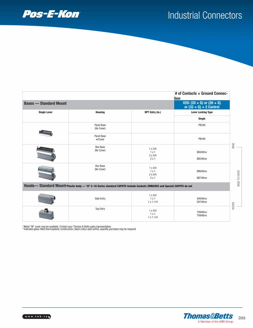
# of Contacts + Ground Connec-
tion
Bases — Standard Mount V20: (20 + G) or (26 + G) or (32 + G) + 2 Control
Single Lever Housing NPT Entry (in.) Lever Locking Type
Single
Panel Base(No Cover)
PB348
Panel Basew/Cover PB448
Box Base(No Cover)
1 x 3/41 x 1
2 x 3/4 2 x 1
BB448mv
BB548mv
Box Base(No Cover) 1 x 3/4
1 x 1 2 x 3/4 2 x 1
BB648mv
BB748mv
Hoods— Standard Mount*Plastic body — “A” 3–16 Series standard CAPOTS include Gaskets: EMBASES and Special CAPOTS do not
Side Entry1 x 3/41 x 1
1 x 1-1/4SH648mvSH748mv
Top Entry1 x 3/41 x 1
1 x 1-1/4
TH848mvTH948mv
† Metal “M” cover may be available. Contact your Thomas & Betts sales representative.* Indicates glass-filled thermoplastic construction, black colour (add suffix); quantity purchase may be required
BA
SE
BA
SE
TO H
OO
D
HO
OD
S

w w w . t n b . c aD34
Industrial ConnectorsTM
6 10 16 24
T Series 16 A 600 VAC
6, 10, 16 & 24 Contacts
+ Ground
• High-temp 200°C rated inserts
• Silicone Viton® seals for moldededge gaskets*
• Corrosion-resistant copper-free aluminum housings with special finish
• UL94V-O ergonomic thermoplastic handles
• Electrostatic epoxy powder-coated finish*Viton® is a trademark of DuPont Performance Elastomers
Crimp Terminal Inserts
Screw Terminal Inserts* 6 + G 10 + G 16 + G 24 + G
Male – Pins20–14 AWG (0.5–2.5 mm2)
MS206T MS210T MS216T MS224T
Female – Sleeves20–14 AWG (0.5–2.5 mm2)
FS106T FS110T FS116T FS124T
* Blocs de connexion may be dark brown or grey in colour

w w w . t n b . c a D35
Industrial ConnectorsTM
Bases — Standard Mount 6 10 16 24NPT
Entry (in.)Lever Locking Type
Single Lever Double Lever Housing Single Double Double Double
Panel Base PB306T PB110T PB116T PB124T
Box Base(No Cover)
1 x 1/2 BB406Tmv BB010Tmv
1 x 3/4 BB016Tmv BB024Tmv
2 x 1/2 BB506Tmv BB110Tmv
2 x 3/4 BB116Tmv BB124Tmv
Hoods— Standard Mount
Side Entry
1 x 1/2 SH606T SH010Tmv
1 x 3/4 SH016TmvSH024TmvSH124Tmv
1 x 1
Top Entry
1 x 1/2 TH806T TH210T
1 x 3/4 TH216T TH224T
1 x 1 TH324Tmv
Coupler Hoods — Inline For inline, portable or special service connections. Coupler Hoods mate to Standard Hoods ONLY.
Top Entry
1 x 1/2 CH806T CH610T
1 x 3/4 CH616Tmv CH624T
1 x 1 CH716T CH724T
Note: Hoods and Bases are black colored to denote special T SeriesB
ASE
HO
OD
S
BA
SE
TO H
OO
DH
OO
D T
O C
OU
PLE
R
CO
UPLE
RS

w w w . t n b . c aD36
Industrial ConnectorsTM
A Series B Series
Specifications DIN VDE 0627/86 DIN VDE 0627/86
DIN VDE 0110/02.79 DIN VDE 0110/02.79
DIN VDE 0110-1/04.97 DIN VDE 0110-1/04.97
IEC 60-664-1, DIN/IEC 512 IEC 60-664-1, DIN/IEC 512
SpecificationsDIN VDE 0627/86
DDIN VDE 0110/02.79
DIN VDE 0110-1/04.97
IEC 60-664-1, DIN/IEC 512
Approvals
MEIE, EZU, SEV
Approvals
MEIE, EZU, SEV
Inserts Contacts (+ Ground ) 3, 4, 10, 16, 32 (2 x 16)
Working Current A3, A4 @ 10 A max. A10–A32 @ 16 A max.
Rated Voltage 600 VAC
Test Voltage 4 kV eff.
Pollution Degree 3
Material Glass-filled thermoplastic
Temperature Range -40°C/-40°F to +125°C /+257°F
Flammability UL94 V-0
Inserts Contacts (+ Ground ) 6, 10, 16, 24, 32 (2 x 16), 48 (2 x 24)
Working Current 16 A max.
Rated Voltage 600 VAC
Test Voltage 3 kV eff.
Pollution Degree 3
Material Glass-filled thermoplastic
Temperature Range -40°C/-40°F to +125°C /+257°F
Flammability UL94 V-0
Contacts Material Solid drilled copper alloy
Surface Hard silver plated
Hard gold plated available
Contact Resistance ≤ 1 milliohm
Screw Terminals Wire AWG
+ with Wire Protection 20–14 AWG (0.5–2.5 mm2)
Crimp Terminals 20–12 AWG (0.5–2.5 mm2)
Contacts Material Solid drilled copper alloy
Surface Hard silver plated
Hard gold plated available
Contact Resistance ≤ 1 milliohm
Screw Terminals Wire AWG
+ with Wire Protection 20–14 AWG (0.5–2.5 mm2)
Crimp Terminals 20–12 AWG (0.5–2.5 mm2)
Housings Materials Die-cast aluminum alloy
EPDM Seal Gaskets Epoxy powder-coat finish
Locking Mechanisms @ A3, 4, 10, 16
Temperature Range -40°C/-40°F to +125°C /+257°F
Internal Protection A3,4: IP44 A10, 16, 32: IP65
per DIN VDE 0470, IEC 529
Housings Materials Die-cast aluminum alloy
EPDM Seal Gaskets Epoxy powder-coat finish
Temperature Range -40°C/-40°F to +125°C /+257°F
Internal Protection IP65 locked positions
per DIN VDE 0470, IEC 529
Thermal Capacity per DIN/IEC 512 Thermal Capacity per DIN/IEC 512
Technical Information
Conductor size 1mm2 Conductor size 2.5mm2
Ambient temperature ( ºC )
Rat
ed c
urre
nt p
er c
onta
ct (
A )
0
I N 16
14
12
10
8
6
4
2
20 40 60 80 100 120 20 40 60 80 100 120
B 24
B 16
B 6
B 10
B 16
B 24
B 10
B 6Conductor size 1mm Conductor size 2.5mmConductor size 1.5mm
2 22
Ambient temperature ( ºC )
Rat
ed o
per
atin
g cu
rren
t p
er c
onta
ct (
A )
0
2
4
6
8
I N 10
12
14
16
20 40 60 80 100 120 20 40 60 80 100 120 20 40 60 80 100 120
A 10Crimp
A 3
A 16CrimpA 10
Screw
A 10Screw
A 16Crimp
A 10Screw
A 3
A 16Screw
A 10Crimp
A 16Screw
A 10Crimp
A 10Screw
A 16Crimp
A 3

w w w . t n b . c a D37
Industrial ConnectorsTM
C Series D Series
Specifications DIN VDE 0627/86 DIN VDE 0627/86
DIN VDE 0110/02.79 DIN VDE 0110/02.79
DIN VDE 0110-1/04.97 DIN VDE 0110-1/04.97
IEC 60-664-1, DIN/IEC 512 IEC 60-664-1, DIN/IEC 512
Specifications DIN VDE 0627/86 DIN 43652
DDIN VDE 0110/02.79
DIN VDE 0110-1/04.97
IEC 60-664-1, DIN/IEC 512
Approvals
MEIE, EZU, SEV
Approvals
MEIE, EZU, SEV
Inserts Contacts (+ Ground ) 6, 12 (2 x 6)
Working Current 35 A
Rated Voltage 600 VAC
Test Voltage 3 kV eff.
Pollution Degree 3
Material Glass-filled thermoplastic
Temperature Range -40°C/-40°F to +125°C /+257°F
Flammability UL94 V-0
Inserts Contacts (+ Ground ) 7, 8, 15, 25, 40, 50 (2 x 25)
64, 80 (2 x 40), 128 (2 x 64)
Working Current 10 A
Rated Voltage 600 VAC
Test Voltage 4 kV eff.
Pollution Degree 3
Material Glass-filled thermoplastic
Temperature Range -40°C/-40°F to +125°C /+257°F
Flammability UL94 V-0
Contacts Material Solid drilled copper alloy
Surface Hard silver plated
Hard gold plated available
Contact Resistance ≤ 0.5 milliohm
Screw Terminals Wire AWG
+ with Wire Protection 20–10 AWG (0.5–6.0 mm2)
+ w/o Wire Protection n/a
Contacts Material Solid drilled copper alloy
Surface Hard silver plated
Hard gold plated available
Contact Resistance ≤ 3 milliohm
Crimp Terminals Wire AWG
26–14 AWG (0.142–2.5 mm2)
> Glass Fiber Optic Cable POF {0} 1mm
Housings Materials Die-cast aluminum alloy
EPDM Seal Gaskets Epoxy powder-coat finish
Temperature Range -40°C/-40°F to +125°C /+257°F
Internal Protection IP65 locked positions
per DIN VDE 0470, IEC 529
Housings Materials Die-cast aluminum alloy
EPDM Seal Gaskets Epoxy powder-coat finish
Temperature Range -40°C/-40°F to +125°C /+257°F
Internal Protection IP65 locked positions
per DIN VDE 0470, IEC 529
Thermal Capacity per DIN/IEC 512 Thermal Capacity per DIN/IEC 512
Technical Information
Conductor size 0.5mm Conductor size 1.5mm2 2
Ambient temperature ( ºC )
Rat
ed o
per
atin
g cu
rren
t p
er c
onta
ct (
A )
0
1
2
8
4
I N 10
9
5
7
6
3
20 40 60 80 100 120 0 20 40 60 80 100 120
D 64D 40
D 25
D 7
D 15
D 64
D 7
D 15D 25
Ambient temperature ( ºC )
Rat
ed c
urre
nt p
er c
onta
ct (
A )
0
35
30
25
20
15
10
5
20 40 60 80 100 120
Conductor size 4mm 2
Conductor size 6mm2
w w w . t n b . c aD38
Industrial ConnectorsTM
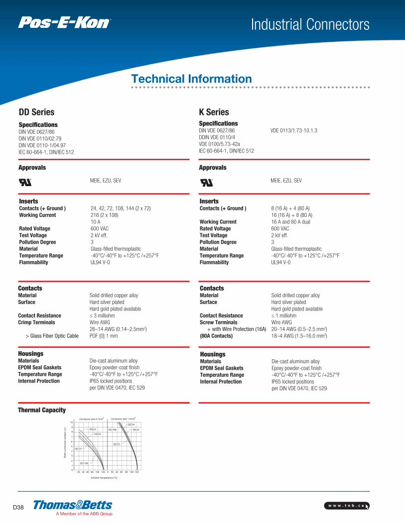
DD Series K Series
Specifications DIN VDE 0627/86
DIN VDE 0110/02.79
DIN VDE 0110-1/04.97
IEC 60-664-1, DIN/IEC 512
Specifications DIN VDE 0627/86 VDE 0113/1.73-10.1.3
DDIN VDE 0110/4
VDE 0100/5.73-42a
IEC 60-664-1, DIN/IEC 512
Approvals
MEIE, EZU, SEV
Approvals
MEIE, EZU, SEV
Inserts Contacts (+ Ground ) 24, 42, 72, 108, 144 (2 x 72)
Working Current 216 (2 x 10⁸)
10 A
Rated Voltage 600 VAC
Test Voltage 2 kV eff.
Pollution Degree 3
Material Glass-filled thermoplastic
Temperature Range -40°C/-40°F to +125°C /+257°F
Flammability UL94 V-0
Inserts Contacts (+ Ground ) 8 (16 A) + 4 (80 A)
16 (16 A) + 8 (80 A)
Working Current 16 A and 80 A dual
Rated Voltage 600 VAC
Test Voltage 2 kV eff.
Pollution Degree 3
Material Glass-filled thermoplastic
Temperature Range -40°C/-40°F to +125°C /+257°F
Flammability UL94 V-0
Contacts Material Solid drilled copper alloy
Surface Hard silver plated
Hard gold plated available
Contact Resistance ≤ 3 milliohm
Crimp Terminals Wire AWG
26–14 AWG (0.14–2.5mm2)
> Glass Fiber Optic Cable POF {0} 1 mm
Contacts Material Solid drilled copper alloy
Surface Hard silver plated
Hard gold plated available
Contact Resistance ≤ 1 milliohm
Screw Terminals Wire AWG
+ with Wire Protection (16A) 20–14 AWG (0.5–2.5 mm2)
(80A Contacts) 18–4 AWG (1.5–16.0 mm2)
Housings Materials Die-cast aluminum alloy
EPDM Seal Gaskets Epoxy powder-coat finish
Temperature Range -40°C/-40°F to +125°C /+257°F
Internal Protection IP65 locked positions
per DIN VDE 0470, IEC 529
Housings Materials Die-cast aluminum alloy
EPDM Seal Gaskets Epoxy powder-coat finish
Temperature Range -40°C/-40°F to +125°C /+257°F
Internal Protection IP65 locked positions
per DIN VDE 0470, IEC 529
Thermal Capacity
Technical Information
Conductor size 1.5mmConductor size 0.7mm2 2
Ambient temperature (ºC)
Rat
er c
urre
nt p
er c
onta
ct (
A )
0
10
9
8
7
6
5
4
3
2
1
20 40 60 80 100 120 0 20 40 60 80 100 120
DD 108
DD 72
DD 24
DD 42
DD 108
DD 72
DD 24
DD 42

w w w . t n b . c a D39
Industrial ConnectorsTM
V Series T Series
SpecificationsDIN VDE 0627/86
DIN VDE 0110/02.79
DIN VDE 0110-1/04.97
IEC 60-664-1, DIN/IEC 512
SpecificationsDIN VDE 0627/86
DDIN VDE 0110/02.79
DIN VDE 0110-1/04.97
IEC 60-664-1, DIN/IEC 512
Approvals
MEIE, EZU, SEV
Approvals
MEIE, EZU, SEV
Inserts Contacts (+ Ground ) 3, 6, 10, 16, 20 (2 x 10)
26 (10+16), 32 (2 x 16)
Working Current 16 A max.
Rated Voltage 600 VAC; switch contacts 400 VAC
Test Voltage 3 kV eff.
Pollution Degree 3
Material Glass-filled thermoplastic
Temperature Range -40°C/-40°F to +125°C /+257°F
Flammability UL94 V-0
Inserts Contacts (+ Ground ) 6, 10, 16, 24 Working Current 16 A max.Rated Voltage 600 VAC; switch contacts 400 VACTest Voltage 3 kV eff.Pollution Degree 3Material Hi-temp thermoplasticTemperature Range -40°C/-40°F to +200°C /+392°FFlammability UL94 V-0
Contacts Material Solid drilled copper alloy
Surface Hard silver plated
Hard gold plated available
Contact Resistance ≤ 1 milliohm
Screw Terminals Wire AWG
+ with Wire Protection 20–14 AWG (0.5–2.5 mm2)
Crimp Terminals 20–12 AWG (0.5–2.5 mm2)
Contacts Material Solid drilled copper alloy
Surface Hard silver plated
Hard gold plated available
Contact Resistance ≤ 1 milliohm
Screw Terminals Wire AWG
+ with Wire Protection 20–14 AWG (0.5–2.5 mm2)
Housings Materials Die-cast aluminum alloy
EPDM Seal Gaskets Epoxy powder-coat finish
Temperature Range -40°C/-40°F to +125°C /+257°F
Internal Protection IP65 locked positions
per DIN VDE 0470, IEC 529
Housings Materials Copper-free die-cast aluminum alloy
Viton® Seal Gaskets Green epoxy powder coating
Temperature Range -40°C/-40°F to +200°C /+392°F
Internal Protection IP65 locked positions
per DIN VDE 0470, IEC 529
Thermal Capacity Thermal Capacity per DIN/IEC 512
Technical Information

w w w . t n b . c aD40
Industrial ConnectorsTM
BA
G
DE
F
.177" A series
.216" B series
BA
C
D
E
F
Pg 11
.Ø 0.125"
5.5
Right Angle Housing
A3/A4
D7/D8
Only
A D
B EF
.177" A Series
.216" B Series
D
E
F
.Ø .125"
A
5.5
B
C
G
Technical Information
BA
C
G
DEF
.216"A D
G
.216" B EC F
* Suffix: A — Aluminum, P — Plastic
Mounting Dimensions for Double Lever Box Bases
Housing Series Dimensions are in inches (millimeters)
A, B, T, K C, V D DD Cat. No. A B C D E F G
A32 D50 BB_32A__ 3.70 (94) 4.17 (106) 5.04 (128) 1.81 (46) 2.20 (56) 2.76 (70) 3.40 (86.5)
B10, T10 V3 DD42 BB_10E 3.23 (82) 3.66 (93 4.33 (110) 1.57 (40) 2.05 (52) 2.28 (58) 2.05 (52)
BB_10EH__ 3.23 (82) 3.66 (93) 4.33 (110) 1.77 (45) 2.24 (57) 2.28 (58) 2.92 (74)
B16, T16 C6, V6 D40 DD72 BB_16E 4.13 (105) 4.61 (117) 5.16 (131) 1.77 (45) 2.24 (57) 2.28 (58) 2.68 (68)
BB_16EH__ 4.13 (105) 4.61 (117) 5.16 (131) 1.77 (45) 2.24 (57) 2.28 (58) 3.31 (84)
B24, T24, V10, V16 D64 DD108 BB_24E 5.20 (132) 5.67 (144) 6.18 (157) 1.77 (45) 2.24 (57) 2.28 (58) 2.68 (68)
K12 BB_24EH__ 5.20 (132) 5.67 (144) 6.18 (157) 1.77 (45) 2.24 (57) 2.28 (58) 3.31 (84)
B32 C12 D80 DD144 BB_32E 4.41 (112) 4.88 (112 5.28 (134) 2.64 (67) 3.20 (81.5) 3.62 (92) 2.83 (72)
Housing Series Dimensions are in inches (millimeters)
A, B, T, K C, V D DD Cat. No. A B C D E F G
A3, A4 D7, D8 BB403A(P)* 1.10 (28) 1.59 (40.5) 1.00 (25.5) 1.42 (36) 1.18 (30) 1.50 (38) —
A10 D15 BB_10A 1.89 (48) — 3.66 (93) 1.57 (40) 1.97 (50) 2.32 (59) 2.05 (52)
A16 D25 BB_16A 2.52 (64) — 4.29 (109) 1.57 (40) 1.97 (50) 2.32 (59) 2.24 (57)
B6, T6 DD24 BB_06 2.76 (70) 3.31 (84) — 1.57 (40) 2.05 (52) 2.72 (69) 2.05 (52)
BB_06H075 2.76 (70) 3.31 (84) — 1.77 (45) 2.24 (57) 2.72 (69) 2.92 (74)
BB_06H100 2.76 (70) 3.31 (84) — 1.77 (45) 2.24 (57) 2.72 (69) 2.92 (74)
B10, T10 V3 DD42 BB_10 3.23 (82) 3.66 (93) — 1.57 (40) 2.05 (52) 2.80 (71) 2.05 (52)
BB_10H0753 3.23 (82) 3.66 (93) — 1.77 (45) 2.24 (57) 2.80 (71) 2.92 (74)
BB_10H100 3.23 (82) 3.66 (93) — 1.77 (45) 2.24 (57) 2.80 (71) 2.92 (74)
B16, T16 C6, V6 D40 DD72 BB_16 4.13 (105) 4.61 (117 — 1.77 (45) 2.24 (57) 2.91 (74) 2.68 (68)
BB_16H___ 4.13 (105) 4.61 (117 — 1.77 (45) 2.24 (57) 2.91 (74) 3.31 (84)
B24, T24 V10, V16 D64 DD108 BB_24 5.20 (132) 5.67 (144) — 1.77 (45) 2.24 (57) 2.91 (74) 2.68 (68)
K12 BB_24H___ 5.20 (132) 5.67 (144) — 1.77 (45) 2.24 (57) 2.91 (74) 3.31 (84)
B48, K24, V20, V26D128 DD216 BB_48 4.37 (111) 5.71 (145)
V32— 4.17 (106) 4.72 (120) 6.18 (157) 3.94 (100)
w w w . t n b . c a D41
Industrial ConnectorsTM
BA
C
G
DEF
.177"
.216" B32 series
A D
G
.177"
.216" B32 SeriesB E
C F
B
C
G
D
E
F
.Ø 0.125"
3
B
A DE
FA series .134"B series .177"
B48 series .248"
A3/A4
D7/D8
Only A D
B EF
G
D
E
F
.Ø .125"
A Series .134"
B Series .177"
B48 Series .248"
G3
B
C
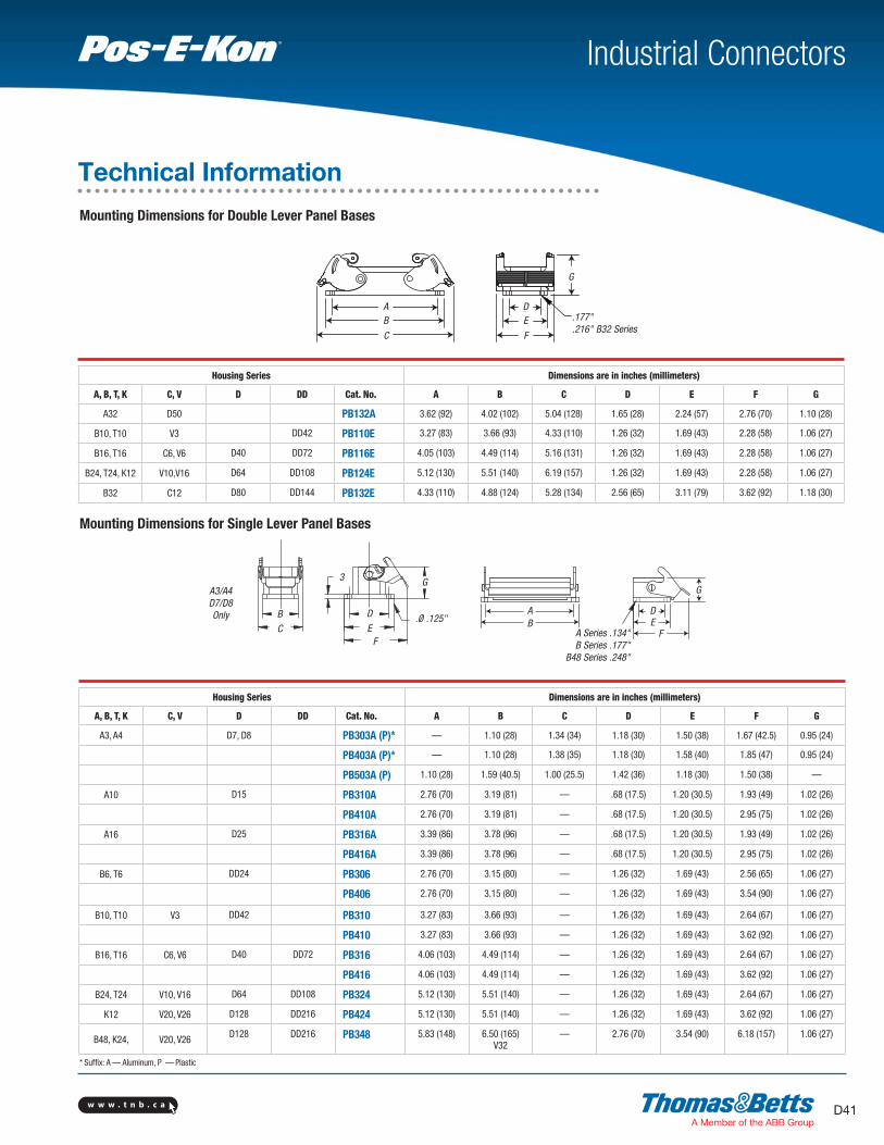
* Suffix: A — Aluminum, P — Plastic
Mounting Dimensions for Double Lever Panel Bases
Mounting Dimensions for Single Lever Panel Bases
Technical Information
Housing Series Dimensions are in inches (millimeters)
A, B, T, K C, V D DD Cat. No. A B C D E F G
A32 D50 PB132A 3.62 (92) 4.02 (102) 5.04 (128) 1.65 (28) 2.24 (57) 2.76 (70) 1.10 (28)
B10, T10 V3 DD42 PB110E 3.27 (83) 3.66 (93) 4.33 (110) 1.26 (32) 1.69 (43) 2.28 (58) 1.06 (27)
B16, T16 C6, V6 D40 DD72 PB116E 4.05 (103) 4.49 (114) 5.16 (131) 1.26 (32) 1.69 (43) 2.28 (58) 1.06 (27)
B24, T24, K12 V10,V16 D64 DD108 PB124E 5.12 (130) 5.51 (140) 6.19 (157) 1.26 (32) 1.69 (43) 2.28 (58) 1.06 (27)
B32 C12 D80 DD144 PB132E 4.33 (110) 4.88 (124) 5.28 (134) 2.56 (65) 3.11 (79) 3.62 (92) 1.18 (30)
Housing Series Dimensions are in inches (millimeters)
A, B, T, K C, V D DD Cat. No. A B C D E F G
A3, A4 D7, D8 PB303A (P)* — 1.10 (28) 1.34 (34) 1.18 (30) 1.50 (38) 1.67 (42.5) 0.95 (24)
PB403A (P)* — 1.10 (28) 1.38 (35) 1.18 (30) 1.58 (40) 1.85 (47) 0.95 (24)
PB503A (P) 1.10 (28) 1.59 (40.5) 1.00 (25.5) 1.42 (36) 1.18 (30) 1.50 (38) —
A10 D15 PB310A 2.76 (70) 3.19 (81) — .68 (17.5) 1.20 (30.5) 1.93 (49) 1.02 (26)
PB410A 2.76 (70) 3.19 (81) — .68 (17.5) 1.20 (30.5) 2.95 (75) 1.02 (26)
A16 D25 PB316A 3.39 (86) 3.78 (96) — .68 (17.5) 1.20 (30.5) 1.93 (49) 1.02 (26)
PB416A 3.39 (86) 3.78 (96) — .68 (17.5) 1.20 (30.5) 2.95 (75) 1.02 (26)
B6, T6 DD24 PB306 2.76 (70) 3.15 (80) — 1.26 (32) 1.69 (43) 2.56 (65) 1.06 (27)
PB406 2.76 (70) 3.15 (80) — 1.26 (32) 1.69 (43) 3.54 (90) 1.06 (27)
B10, T10 V3 DD42 PB310 3.27 (83) 3.66 (93) — 1.26 (32) 1.69 (43) 2.64 (67) 1.06 (27)
PB410 3.27 (83) 3.66 (93) — 1.26 (32) 1.69 (43) 3.62 (92) 1.06 (27)
B16, T16 C6, V6 D40 DD72 PB316 4.06 (103) 4.49 (114) — 1.26 (32) 1.69 (43) 2.64 (67) 1.06 (27)
PB416 4.06 (103) 4.49 (114) — 1.26 (32) 1.69 (43) 3.62 (92) 1.06 (27)
B24, T24 V10, V16 D64 DD108 PB324 5.12 (130) 5.51 (140) — 1.26 (32) 1.69 (43) 2.64 (67) 1.06 (27)
K12 V20, V26 D128 DD216 PB424 5.12 (130) 5.51 (140) — 1.26 (32) 1.69 (43) 3.62 (92) 1.06 (27)
B48, K24, V20, V26D128 DD216 PB348 5.83 (148) 6.50 (165)
V32— 2.76 (70) 3.54 (90) 6.18 (157) 1.06 (27)

w w w . t n b . c aD42
B
A CD
E
A
B
E
C
D
Industrial ConnectorsTM
Technical InformationMounting Dimensions for Screw and Crimp Terminal Inserts
Housing Series Dimensions are in inches (millimeters)
A, B, T, K C, V D DD Mating A B C D E
A3, A4 BOTH — 0.83 (21) — 0.83 (21) 0.98 (25)
D7, D8 FEMALE — 0.83 (21) — 0.83 (21) 1.25 (31.8)
MALE — 0.83 (21) — 0.83 (21) 1.19 (30.2)
A10 D15 FEMALE 1.95 (49.5) 2.22 (56.5) 0.63 (16) 1.34 (34) 1.14 (29)
MALE 1.95 (49.5) 2.22 (56.5) 0.63 (16) 1.34 (34) 1.26 (32)
A16 D25 FEMALE 2.60 (66) 2.87 (73) 0.63 (16) 1.34 (34) 1.14 (29)
MALE 2.60 (66) 2.87 (73) 0.63 (16) 1.34 (34) 1.26 (32)
A32 D50 FEMALE 2.60 (66) 2.87 (73) 0.63 (16) x 2 1.34 (34) 1.14 (29)
MALE 2.60 (66) 2.87 (73) 0.63 (16) x 2 1.34 (34) 1.26 (32)
B6, T6 DD24 FEMALE 1.73 (44) 2.01 (51) 1.063 (27) 1.34 (34) 1.46 (37)
MALE 1.73 (44) 2.01 (51) 1.063 (27) 1.34 (34) 1.38 (35)
B10, T10 V3 DD42 FEMALE 2.24 (57) 2.52 (64) 1.063 (27) 1.34 (34) 1.46 (37)
MALE 2.24 (57) 2.52 (64) 1.063 (27) 1.34 (34) 1.38 (35)
B16, T16 C6, V6 D40 DD72 FEMALE 3.05 (77.5) 3.33 (84.5) 1.063 (27) 1.34 (34) 1.48 (37.5)
MALE 3.05 (77.5) 3.33 (84.5) 1.063 (27) 1.34 (34) 1.40 (35.5)
B24, T24, V10, V16 D64 DD108 FEMALE 4.09 (104) 4.37 (111) 1.063 (27) 1.34 (34) 1.48 (37.5)
K12 MALE 4.09 (104) 4.37 (111) 1.063 (27) 1.34 (34) 1.40 (35.5)
B32 C12 D80 DD144 FEMALE 3.05 (77.5) 3.33 (84.5) 1.063 (27) x 2 1.34 (34) 1.48 (37.5)
MALE 3.05 (77.5) 3.33 (84.5) 1.063 (27) x 2 1.34 (34) 1.40 (35.5)
B48, K24 V20, V26, V32 D128 DD216 FEMALE 4.09 (104) 4.37 (111) 1.063 (27) x 2 1.34 (34) 1.48 (37.5)
MALE 4.09 (104) 4.37 (111) 1.063 (27) x 2 1.34 (34) 1.40 (35.5)

w w w . t n b . c a D43
Industrial ConnectorsTM
Series Screw Location Unit of Measure Pozi-Drive Point Std. Straight-Blade Screwdriver Screwdriver
A3, A4 Wire Termination Screw Newton meters 0.4 0.9
Inch ounces 57 127
Insert Grounding Screw Newton meters 0.6 0.8
Inch ounces 85 113
D7, D8 D7, D8 Insert Grounding Screw Newton meters 0.4
0.4
Inch ounces 57 57
A10, A16, A32 Wire Termination Screw Newton meters 0.4 0.9
Inch ounces 57 127
Insert Fastening Screw Newton meters 0.71 0.1
Inch ounces 99 156
Insert Grounding Screw Newton meters 0.7 1.3
Inch ounces 99 184
D15, D25, D50 Insert Fastening Screw Newton meters 0.7 1.1
Inch ounces 99 156
Insert Grounding Screw Newton meters 0.7 1.3
Inch ounces 99 184
B, T, V Wire Termination Screw Newton meters 0.4 0.6
Inch ounces 57 85
Insert Fastening Screw Newton meters 0.7 1.1
Inch ounces 99 156
Insert Grounding Screw Newton meters 1.2 1.9
Inch ounces 170 269
C Wire Termination Screw Newton meters 0.7 1.3
Inch ounces 99 184
Insert Fastening Screw Newton meters 0.7 1.1
Inch ounces 99 156
Insert Grounding Screw Newton meters 2.3 2.3
Inch ounces 326 326
K Wire Termination Screw Newton meters 0.5/1.4* —
Inch ounces 71/198* —
Insert Fastening Screw Newton meters 0.7 —
Inch ounces 99 —
Insert Grounding Screw Newton meters 2.3 —
Inch ounces 326 —
• Insert Mounting Screws accept a Pozi-drive screwdriver head
• Common cross-point or bladed screwdrivers will also work
• Specs refer to Pozi-drive or bladed common torque only
* 16A/80A contacts
Note: Inch ounces/16.0 = Pound/Inches
Insert Screw Torque Specifications
Technical Information

w w w . t n b . c aD44
E
A D
B
H
G
C F
Industrial ConnectorsTM
Technical Information
Insert Series Cat. No. Dimensions are in inches (millimeters)
A B C D E f g H
B6
FS106WAL
1.73 (44) 2.01 (51) 1.03 (26.3) 1.06 (27) 1.34 (34) 1.77 (45) 2.28 (58) 3.54 (90)FS106WAR
MS206WAL
MS206WAR
B10
FS110WAL
2.13 (54) 2.52 (64) 1.55 (39.5) 1.06 (27) 1.34 (34) 1.77 (45) 2.28 (58) 3.54 (90)FS110WAR
MS210WAL
MS210WAR
B16
FS116WAL
3.05 (77.5) 3.32 (84.5) 2.33 (59.3) 1.06 (27) 1.34 (34) 1.77 (45) 2.28 (58) 3.54 (90)FS116WAR
MS216WAL
MS216WAR
B24
FS124WAL
4.09 (104) 4.37 (111) 3.36 (85.7) 1.06 (27) 1.34 (34) 1.77 (45) 2.28 (58) 3.54 (90)FS124WAR
MS224WAL
MS224WAR
D40FS340WAL
3.05 (77.5) 3.27 (83) 2.21 (56) 1.06 (27) 1.34 (34) 3.19 (81) 4.53 (115) 5.12 (130)MS440WAL
D64FS364WAL
4.09 (104) 4.33 (110) 3.39 (86.3) 1.06 (27) 1.34 (34) 3.19 (81) 4.53 (115) 5.12 (130)MS464WAL
-WAL — ground left, -WAR — ground right
Mounting Dimensions for Wiring Adapters

w w w . t n b . c a D45
Industrial ConnectorsTM
* Dimensions reflect dual inserts mounting
Housing Series Dimensions are in inches (millimeters)
A, B, T, K C, V D DD A B C D E
A3, A4 D7, D8 0.83 (21) 1.18 (30) 0.83 (21) — 0.125 (3.2)
A10 D15 1.71 (43.5) 2.76 (70) 0.95 (24) 0.68 (17.5) 0.134 (3.4)
A16 D25 2.36 (60) 3.39 (86) 0.95 (24) 0.68 (17.5) 0.134 (3.4)
A32 D50 2.36 (60) 3.62 (92) 1.89 (48) 1.65 (28) 0.177 (4.5)
B6, T6 DD24 1.42 (36) 2.76 (70) 1.38 (35) 1.26 (32) 0.177 (4.5)
B10, T10 V3 DD42 1.93 (49) 3.27 (83) 1.38 (35) 1.26 (32) 0.177 (4.5)
B16, T16 C6, V6 D40 DD72 2.84 (72) 4.06 (103) 1.38 (35) 1.26 (32) 0.177 (4.5)
B24, T24, K12 V10, V16 D64 DD108 3.86 (98) 5.12 (130) 1.38 (35) 1.26 (32) 0.177 (4.5)
B32 C12 D80 DD144 2.84 (72) 4.33 (110) 2.80 (71) 2.56 (65) .216 (5.5)
B48, K24V20, V26,
D128 DD216 3.86 (98) 5.83 (148) 2.80 (71) 2.76 (70) .248 (6.3)V32
Panel Cut Out Dimensions for Panel Bases
Technical Information
A3/A4D7/D8Only

w w w . t n b . c aD46
A B
C
Industrial ConnectorsTM
Technical Information
Housing Series Dimensions are in inches (millimeters)
Cat. No. A, B, t, k c, v D DD A B C
SH_32A A32 — D50 — 3.23 (82) 2.21 (56) 2.99 (76)
TH_32A — — — — 3.23 (82) 2.21 (56) 2.99 (76)
SH_10 — — — — 2.87 (73) 1.69 (43) 2.05 (52)
M3SH_10H___ B10, T10 V3 — DD42 2.87 (73) 1.69 (43) 2.05 (52)
TH_10 — — — — 2.87 (73) 1.69 (43) 2.05 (52)
TH_10H___ — — — — 2.87 (73) 1.69 (43) 2.05 (52)
SH_16 — — — — 3.70 (94) 1.69 (43) 2.56 (65)
SH_16H — — — — 3.70 (94) 1.69 (43) 2.99 (76)
M5SH_16L B16, T16 C6, V6 D40 DD72 3.70 (94) 1.69 (43) 2.36 (60)
TH_16 — — — — 3.70 (94) 1.69 (43) 2.56 (65)
TH_16H — — — — 3.70 (94) 1.69 (43) 2.99 (76)
TH_16L — — — — 3.70 (94) 1.69 (43) 2.36 (60)
SH_24 — — — — 4.72 (120) 1.69 (43) 2.36 (60)
SH_24H — — — — 4.72 (120) 1.69 (43) 2.99 (76)
M7TH_24 B24, T24, K12 V10, V16 D64 DD108 4.72 (120) 1.69 (43) 2.21 (56)
TH_24H — — — — 4.72 (120) 1.69 (43) 2.99 (76)
TH424RC — — — — 4.72 (120) 1.69 (43) 2.99 (76)
SH_32 B32 C12 D80 DD144 3.70 (94) 3.11 (79) 3.15 (80)
TH_32 — — — — 3.70 (94) 3.11 (79) 3.15 (80)
Suffix: A — Aluminum, P — Plastic, H — High Profile, L — Low Profile, RC — Ribbon Cable (top entry only)
Mounting Dimensions for Double Post Hoods

w w w . t n b . c a D47
A B
C
Industrial ConnectorsTM
Suffix: AP — Plastic, H — High Profile, L — Low Profile, RC — Ribbon Cable (top entry only)
Housing Series Dimensions are in inches (millimeters)
Cat. No. A, B, t, k c, v D DD a b c
SH603A(P)V A3, A4 — D7, D8 — 1.04 (26.5) 1.04 (26.5) 1.89 (48)
TH803A(P)V — — — — 1.04 (26.5) 1.04 (36.5) 1.89 (48)
SH_10A — — — — 2.48 (63) 1.42 (36) 2.60 (66)
SH_10AL A10 — D15 — 2.48 (63) 1.16 (29.5) 2.09 (53)
TH_10A — — — — 2.48 (63) 1.42 (36) 2.60 (66)
TH_10AL — — — — 2.48 (63) 1.16 (29.5) 2.09 (53)
SH_16A — — — — 3.13 (79.5) 1.42 (36) 2.84 (72)
SH_16AL A16 — D25 — 3.13 (79.5) 1.16 (29.5) 2.28 (58)
TH_16A — — — — 3.13 (79.5) 1.42 (36) 2.84 (72)
TH_16AL — — — — 3.13 (79.5) 1.16 (29.5) 2.28 (58)
SH_606 — — — — 2.36 (60) 1.69 (43) 1.69 (43)
M2SH_606Hxxx B6, T6 — — DD24 2.36 (60) 1.69 (43) 2.84 (72)
TH_806 — — — — 2.36 (60) 1.69 (43) 1.69 (43)
TH_806Hxxx — — — — 2.36 (60) 1.69 (43) 2.84 (72)
SH_610 — — — — 2.87 (73) 1.69 (43) 2.05 (52)
M3SH_610Hxxx B10, T10 V3 — DD42 2.87 (73) 1.69 (43) 2.84 (72)
TH_810 — — — — 2.87 (73) 1.69 (43) 2.05 (52)
TH_810Hxxx — — — — 2.87 (73) 1.69 (43) 2.84 (72)
SH_616 — — — — 3.70 (94) 1.69 (43) 2.56 (65)
SH_616H — — — — 3.70 (94) 1.69 (43) 2.99 (76)
SH_616L — — — — 3.70 (94) 1.69 (43) 2.36 (60)
M5TH_816 B16, T16 C6, V6 D40 DD72 3.70 (94) 1.69 (43) 2.56 (65)
TH_816H — — — — 3.70 (94) 1.69 (43) 2.99 (76)
TH_816L — — — — 3.70 (94) 1.69 (43) 2.36 (60)
TH816RC — — — — 3.70 (94) 1.69 (43) 2.99 (76)
SH_624 — — — — 4.72 (120) 1.69 (43) 2.99 (76)
M7SH_624L B24, T24 V10, V16 D64 DD108 4.72 (120) 1.69 (43) 2.36 (60)
TH_824 — — — — 4.72 (120) 1.69 (43) 2.99 (76)
TH824L K12 — — — 4.72 (120) 1.69 (43) 2.36 (60)
TH624RC — — — — 4.72 (120) 1.69 (43) 2.99 (76)
SH_48 B48, K24 V20, V26 D128 DD216 5.16 (131.5) 3.50 (89) 3.78 (96)
TH_48 — V32 — — 5.16 (131.5) 3.50 (89) 3.78 (96)
Mounting Dimensions for Single Post Hoods
Technical Information

w w w . t n b . c aD48
Industrial ConnectorsTM
Technical Information
Housing Series Dimensions are in inches (millimeters)
Cat. No. A, B, t, k c, v D DD A B C D E
CH610EB10, T10 V3 DD42
2.87 (73) 4.33 (110) 1.69 (43) 2.28 (58) 2.02 (51.5)
CH610EHxxx 2.87 (73) 4.33 (110) 1.69 (43) 2.28 (58) 2.87 (73)
CH_16E 3.70 (94) 5.16 (131) 1.69 (43) 2.28 (58) 2.72 (69)
CH_16EH B16, T16 C6, V6 D40 DD72 3.70 (94) 5.16 (131) 1.69 (43) 2.28 (58) 3.15 (80)
CH616ERC 3.70 (94) 5.16 (131) 1.69 (43) 2.28 (58) 3.15 (80)
CH_24E B24, T24C6, V6 D40 DD72
4.72 (120) 6.18 (157) 1.69 (43) 2.28 (58) 3.15 (80)
CH624ERC K12 4.72 (120) 6.18 (157) 1.69 (43) 2.28 (58) 3.15 (80)
CH_32E B32 C12 D80 DD144 3.70 (94) 5.28 (134) 3.11 (79) 3.62 (92) 3.23 (82)
H — High Profile, RC — Ribbon Cable (top entry only)
*Suffix: A — Aluminum, P — Plastic, H — High Profile, L — Low Profile, RC — Ribbon Cable (top entry only)
Housing Series Dimensions are in inches (millimeters)
Cat. No. A, B, t, k c, v D DD A B C D E
CH803A(P)* A3, A4 D7, D8 1.34 (34) — 1.04 (26.5) 1.43 (36.5) 2.02 (51.5)
CH810A A10 D15 2.48 (63) — 1.16 (29.5) 1.92 (49) 1.89 (48)
CH816A A16 C6, V6 D25 3.13 (79.5) — 1.16 (29.5) 1.92 (49) 2.09 (53)
CH806B6, T6 DD24
2.36 (60) — 1.69 (43) 2.56 (65) 2.02 (51.5)
CH806Hxxx 2.36 (60) — 1.69 (43) 2.56 (65) 2.87 (73)
CH810B10, T10 V3 DD24
2.87 (73) — 1.69 (43) 2.64 (67) 2.02 (51.5)
CH810Hxxx 2.87 (73) — 1.69 (43) 2.64 (67) 2.87 (73)
CH_16 3.70 (94) — 1.69 (43) 2.64 (67) 2.72 (69)
CH_16H B16, T16 C6, V6 D40 DD72 3.70 (94) — 1.69 (43) 2.64 (67) 3.15 (80)
CH616RC 3.70 (94) — 1.69 (43) 2.64 (67) 3.15 (80)
CH_24B24, T24 V10, V16 D64 DD108
4.72 (120) — 1.69 (43) 2.64 (67) 3.15 (80)
CH824RC 4.72 (120) — 1.69 (43) 2.64 (67) 3.15 (80)
A3/A4
D7/D8
Only
CD
Mounting Dimensions for Double Lever Coupler Hoods
Mounting Dimensions for Single Lever Coupler Hoods
A
B D
C
E
A
A B
DE
C
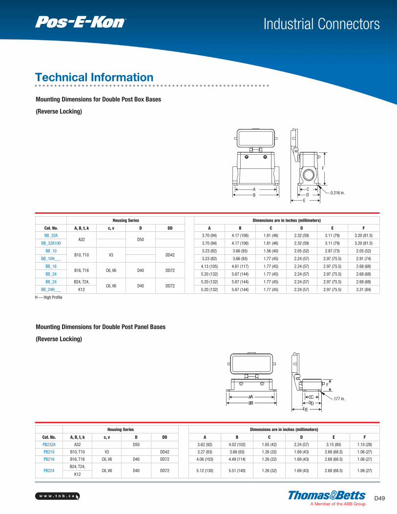
w w w . t n b . c a D49
Industrial ConnectorsTM
H — High Profile
CD
E
A
B
F
.177 in.
Housing Series Dimensions are in inches (millimeters)
Cat. No. A, B, t, k c, v D DD A B C D E F
BB_32AA32 D50
3.70 (94) 4.17 (106) 1.81 (46) 2.32 (59) 3.11 (79) 3.20 (81.5)
BB_32A100 3.70 (94) 4.17 (106) 1.81 (46) 2.32 (59) 3.11 (79) 3.20 (81.5)
BB_10B10, T10 V3 DD42
3.23 (82) 3.66 (93) 1.56 (40) 2.05 (52) 2.87 (73) 2.05 (52)
BB_10H___ 3.23 (82) 3.66 (93) 1.77 (45) 2.24 (57) 2.97 (75.5) 2.91 (74)
BB_16B16, T16 C6, V6 D40 DD72
4.13 (105) 4.61 (117) 1.77 (45) 2.24 (57) 2.97 (75.5) 2.68 (68)
BB_24 5.20 (132) 5.67 (144) 1.77 (45) 2.24 (57) 2.97 (75.5) 2.68 (68)
BB_24 B24, T24,C6, V6 D40 DD72
5.20 (132) 5.67 (144) 1.77 (45) 2.24 (57) 2.97 (75.5) 2.68 (68)
BB_24H___ K12 5.20 (132) 5.67 (144) 1.77 (45) 2.24 (57) 2.97 (75.5) 3.31 (84)
Housing Series Dimensions are in inches (millimeters)
Cat. No. A, B, t, k c, v D DD A B C D E F
PB232A A32 D50 3.62 (92) 4.02 (102) 1.65 (42) 2.24 (57) 3.15 (80) 1.10 (28)
PB210 B10, T10 V3 DD42 3.27 (83) 3.66 (93) 1.26 (32) 1.69 (43) 2.68 (68.5) 1.06 (27)
PB216 B16, T16 C6, V6 D40 DD72 4.06 (103) 4.49 (114) 1.26 (32) 1.69 (43) 2.68 (68.5) 1.06 (27)
PB224B24, T24,
C6, V6 D40 DD72 5.12 (130) 5.51 (140) 1.26 (32) 1.69 (43) 2.68 (68.5) 1.06 (27)K12
Mounting Dimensions for Double Post Box Bases
(Reverse Locking)
Mounting Dimensions for Double Post Panel Bases
(Reverse Locking)
Technical Information
C
D
E
A
B
F
0.216 in.

w w w . t n b . c aD50
A
E
C
B D
Industrial ConnectorsTM
Technical Information
Housing Series For Single-LeverHousings
For Double-LeverHousings
For Single-PostHousings
For Double-PostHousingsA, B, T, K C, V D DD
A3, A4 D7, D8 DCL103A-1
A10 D15 DCL110A-1 DCS110A-1
A16 D25 DCL116A-1 DCS116A-1
A32 D50 DCL232A-1/DCL432A-1* DCS232A-1
B6, T6** DD24 DCL106B-1
B10, T10** V3 DD42 DCL110B-1 DCL210B-1/DCL410B-1*
B16, T16** C6, V6 D40 DD72 DCL116B-1 DCL216B-1/DCL416B-1*
B24, T24**, K12 V10, V16 D64 DD108 DCL124B-1 DCL224B-1/DCL424B-1*
* Comes with gasket for hoods with levers and without gaskets
** Dust covers tested only to 125°C (if applied to 200°C Series T)
* Install with silicone sealant/adhesive for industrial use** For T Series 200°C applications, specify catalogue number except use “T” prefix instead of “B” for gaskets. EX: use “T16XFGP” for panel base gaskets.
Cat. No. Housing Series
Panel Base, Flat Molded Edge Contour* A, B, T, K C, V D DD
A04XFGP A04XMEC A3, A4 D7, D8
A10XFGP A10XMEC A10 D15
A16XFGP A16XMEC A16 D25
A32XFGP A32XMEC A32 D50
B6XFGP B6XMEC B6, T6** DD24
B10XFGP B10XMEC B10, T10** V3 DD42
B16XFGP B16XMEC B16, T16** V6, C6 D40 DD72
B24XFGP B24XMEC B24, T24**, K12 V10, V16 D64 DD108
B32XFGP B32XMEC B32 C12 D80 DD144
B48XFGP B48XMEC B48, K24 V20, V26, V32 D128 DD216
Housing Series Dimensions are in inches (millimeters)
Cat. No. A, B, t, k c, v D DD A B C D E
LH_32A A32 D50 3.23 (82) 5.04 (128) 2.21 (56) 2.76 (70) 2.99 (76)
LH_10EB10, T10 V3 DD42
2.87 (73) 4.33 (110) 1.69 (43) 2.28 (58) 1.89 (48)
LH_10EH___ 2.87 (73) 4.33 (110) 1.69 (43) 2.28 (58) 2.84 (72)
LH_16EB16, T16 C6, V6 D40 DD72
3.70 (94) 5.16 (131) 1.69 (43) 2.28 (58) 2.56 (65)
LH_16EH 3.70 (94) 5.16 (131) 1.69 (43) 2.28 (58) 2.99 (76)
LH_24E B24, T24, K12 V10, V16 D64 DD108 4.72 (120) 6.18 (157) 1.69 (43) 2.28 (58) 2.99 (76)
Mounting Dimensions for Double Lever Hoods
(Reverse Locking)
Dust Covers for Housings
Gaskets

w w w . t n b . c a D51
Industrial ConnectorsTM
MG601 FG602
Guide Pins and Sleeves:
Perform same function as coding pins and/or aid high-density insert mating as well
Coding possibilities for single insert series
Coding possibilities for double insert series
Coding possibilities for single insert series
Coding possibilities for double insert series
Guide Pin Guide Sleeve
PC600
Coding Pins:
Used for rejection in multiple “same size or series” insert/hood installations Patterns show examples of rejection coding pins installed
Coding Pin
– Male Guide Pins or Coding Pins
– Female Guide Sleeves
– Mounting Screw
Coding Pins, Guide Pins and Sleeves can be used
in all series housings, with all inserts
Technical Information

w w w . t n b . c aD52
Industrial ConnectorsTM
Supplied standard with all hoods and bases Special sizes/hood combinations available
Standard European style — can be specified/supplied with hoods and bases
* Plastic
Metric PG-to-NPT Thread Adapters
Cat. No. NPT Thread (mating) (in.) Thread (at Housing)
PG11-38 3/8 PG11
PG16-50 1/2 PG16
PG21-75 3/4 PG21
PG29-100 1 PG29
PG29-125 1-1/4 PG29
PG36-125 1-1/4 PG36
PG36-150 1-1/2 PG36
PG42-200 2 PG42
Metric ISO-to-NPT Thread Adapters
Cat. No. NPT Thread (mating) (in.) Thread (at Housing)
M20-50 1/2 M20
M25-75 3/4 M25
M32-100 1 M32
Metric Cord Grip Connectors
Cat. No.Cable O.D. (in.) Thread
(at Housing)Min. Max.
CG11-38 0.200 0.470 PG11
Cg11-38P* 0.325 0.340 PG11
Cg135-50 0.285 0.545 PG13.5
Cg16-50 0.285 0.625 PG16
Cg21-75 0.395 0.790 PG21
CG29-100 0.780 0.060 PG291
Technical Information

w w w . t n b . c a D53
Industrial ConnectorsTM
Conduit Entry Blind Plug
Cat. No. Thread (at housing)
CXP722 PG13.5
CXP723 PG16
CXP724 PG21
CXP725 PG29
Nonmetallic Cord Grip Fittings
NPT ThreadsCat. No.
Cord Range Thread Size(in.)in. mm
CC-NPT38-G 0.197–0.394 5–10 3/8
CC-NPT12-G 0.394–0.551 10–14 1/2
CC-NPT34-G 0.512–0.709 13–18 3/4
CC-NPT1-G 0.709–0.984 18–25 1
Metric Cord Grip Connectors
PG ThreadsCat. No.
Cord Range Thread Size(in.)in. mm
CC-PG11-G 0.197–0.394 5–10 11
CC-PG135-G 0.336–0.473 6–12 13.5
CC-PG16-G 0.394–0.551 10–14 16
CC-PG21-G 0.512–0.709 13-18 21
CC-PG29-G 0.709–0.984 18–25 29
CC-PG36-G 0.867–0.1.26 22–32 36
Technical Information

w w w . t n b . c aD54
Industrial ConnectorsTM
1. Before crimping the POF* cable, 1.0 mm to the glass fiber
cable contact, the end of the fiber has to be polished.
Stick end of POF cable into polishing tool and grind on a
plane surface (e.g. glass plate). Wipe off any residues after
polishing. The best optical damping values are achieved
with wet-polishing procedure.
2. Strip 1.0 mm POF cable on min. 14 mm for D sleeve
contacts and min. 19 mm for D pin contacts.
3. Insert stripped POF cable in sleeve or pin contact until
stop. The optical fiber should then stick about 1 mm out
of the contact.
4. Optical fiber crimping:
Adjust the positioning sleeve into the corresponding
inlet of the crimping tool with the stop screw at 1.45 mm
(if necessary check with gauge pin, diameter 1.45 mm,
with closed crimping tool).
Insert the glass fiber cable contact together with the POF
cable through the crimp opening of the crimping tool into
the positioning sleeve.
By pressure on the contact, the fiber inside the contact
will be locked into the right position for the fiber crimping.
Continue pressure until the release mechanism is heard.
* POF = Polymer Optical Fiber
Technical Information
Instructions for Connection with Fiber Optic (POF Cable)
Polishing tool
For sleeve contacts min. 14 mm
For pin contacts min. 19 mm
Sleeve contact about 1.0 mmPin contact about 1.0 mm
Crimping area sleeve contact
Crimping area pin contact
Positioning sleeve
glass fiber contact