SECTION 8B CORROSION PROTECTION – PLASTIC PIPE SYSTEMS...
84
CITY OF RAPID CITY Page 8B.1 STANDARD SPECIFICATIONS FOR PUBLIC WORKS CONSTRUCTION CORROSION PROTECTION – PLASTIC PIPE SYSTEMS SECTION 8B CORROSION PROTECTION – PLASTIC PIPE SYSTEMS 8B.1 GENERAL 1.01 WORK INCLUDED A. This work consists of furnishing and installing cathodic protection for all water mains, service lines and appurtenances. This includes all equipment, tools, materials, labor and other incidentals to provide a complete system ready for immediate and continuous use. The work includes, but is not limited to the following: 1. Coatings on all ferrous metal (steel, ductile iron, cast iron) piping and fittings; 2. Galvanic anodes, joint bonds, insulating joints, test stations, and tracer wire to form an electrically continuous piping network; 3. Labeling, marking, and testing of cathodic protection system. 1.02 RELATED WORK A. Not all sections listed in Related Work may be applicable to this contract: B. Section 7 - General Conditions C. Section 8A - Water Piping Systems D. Section 9 - Sanitary Sewer E. Section 11 - Utility Excavation and Backfill F. Section 41 - Utility Trench Resurfacing G. Section 56 - Concrete for Incidental Construction (Class M) H. Section 90 - Traffic Control I. Section 112 - Select Granular Backfill J. Section 200 - Controlled Low Strength Material 1.03 REFERENCE STANDARDS A. The latest revision of the following minimum standards shall apply to the materials and installation included in this specification, except where more stringent standards are applicable. In case of conflict, the most stringent requirements shall apply. 1. American National Standards Institute (ANSI): a) C80.1-90, Rigid Steel Conduit-Zinc Coated. b) ANSI/NSF Standard 61 Drinking Water System Components – Health Effects 2. American Society for Testing and Materials (ASTM): a) ASTM -A380, Standard Practice for Cleaning, Descaling and Passivation of Stainless Steel Parts, Equipment and Systems
-
Upload
trinhxuyen -
Category
Documents
-
view
217 -
download
0
Transcript of SECTION 8B CORROSION PROTECTION – PLASTIC PIPE SYSTEMS...
CITY OF RAPID CITY Page 8B.1STANDARD SPECIFICATIONS FOR PUBLIC WORKS CONSTRUCTION CORROSION PROTECTION – PLASTIC PIPE SYSTEMS
SECTION 8B
CORROSION PROTECTION – PLASTIC PIPE SYSTEMS
8B.1 GENERAL
1.01 WORK INCLUDED
A. This work consists of furnishing and installing cathodic protection for all water mains, service lines and appurtenances. This includes all equipment, tools, materials, labor and other incidentals to provide a complete system ready for immediate and continuous use. The work includes, but is not limited to the following:
1. Coatings on all ferrous metal (steel, ductile iron, cast iron) piping and fittings;
2. Galvanic anodes, joint bonds, insulating joints, test stations, and tracer wire to form an electrically continuous piping network;
3. Labeling, marking, and testing of cathodic protection system.
1.02 RELATED WORK
A. Not all sections listed in Related Work may be applicable to this contract: B. Section 7 - General Conditions C. Section 8A - Water Piping Systems D. Section 9 - Sanitary Sewer E. Section 11 - Utility Excavation and Backfill F. Section 41 - Utility Trench Resurfacing G. Section 56 - Concrete for Incidental Construction (Class M) H. Section 90 - Traffic Control I. Section 112 - Select Granular Backfill J. Section 200 - Controlled Low Strength Material
1.03 REFERENCE STANDARDS
A. The latest revision of the following minimum standards shall apply to the materials and installation included in this specification, except where more stringent standards are applicable. In case of conflict, the most stringent requirements shall apply.
1. American National Standards Institute (ANSI):
a) C80.1-90, Rigid Steel Conduit-Zinc Coated.
b) ANSI/NSF Standard 61 Drinking Water System Components – Health Effects
2. American Society for Testing and Materials (ASTM):
a) ASTM -A380, Standard Practice for Cleaning, Descaling and Passivation of Stainless Steel Parts, Equipment and Systems

CITY OF RAPID CITY Page 8B.2STANDARD SPECIFICATIONS FOR PUBLIC WORKS CONSTRUCTION CORROSION PROTECTION – PLASTIC PIPE SYSTEMS
b) ASTM A967 Standard Specification for Chemical Passivation Treatments for Stainless Steel Parts
c) ASTM B418, Standard Specification for Cast and Wrought Galvanic Zinc Anodes.
d) ASTM B843, Standard Specification for Magnesium Alloy Anodes for Cathodic Protection
e) ASTM G97, Laboratory Evaluation of Magnesium Anode Test Specimens for Underground Application.
3. American Water Works Association (AWWA):
a) AWWA C116, Protective Fusion-Bonded Epoxy Coatings for the Interior and Exterior Surfaces of Ductile-Iron and Gray-Iron Fittings for Water Supply Service.
b) AWWA C209, Cold-Applied Tape Coatings for the Exterior of Special Sections, Connections, and Fittings for Steel Water Pipelines.
c) AWWA C210, Liquid Epoxy Coating System for the Interior and Exterior of Steel Water Pipelines.
d) AWWA C213, Fusion Bonded Epoxy Coating for the Interior and Exterior of Steel Water Pipelines.
e) AWWA C214, Tape Coating Systems for the Exterior of Steel Water Pipelines.
f) AWWA C216, Heat-Shrinkable Cross-Linked Polyolefin Coatings for the Exterior of Special Sections, Connections, and Fittings for Steel Water Pipelines.
g) AWWA C217, Cold-Applied Petrolatum Tape and Petroleum Wax Tape Coatings for the Exterior of Special Sections, Connections, and Fittings for Steel Water Pipelines.
h) AWWA C219, Bolted, Sleeve-Type Couplings for Plain-End Pipe
i) AWWA C550, Protective Epoxy Interior Coatings for Valves and Hydrants.
4. National Association of Corrosion Engineers International (NACE),
a) Standard Practice, SP0169, Control of External Corrosion on Underground or Submerged Metallic Piping Systems.
5. National Electrical Manufacturers Association (NEMA):
a) I-10, Type R and 4X Enclosures
b) TC 2-83, Electrical Plastic Tubing (EPT) and Conduit (EPC-40 and EPC-80).
c) WC 3-80, Rubber-Insulated Wire and Cable for the Transmission and Distribution of Electrical Energy (R 1986).
d) WC 5-73, Thermoplastic-Insulated Wire and Cable for the Transmission and Distribution of Electrical Energy (R 1985).

CITY OF RAPID CITY Page 8B.3STANDARD SPECIFICATIONS FOR PUBLIC WORKS CONSTRUCTION CORROSION PROTECTION – PLASTIC PIPE SYSTEMS
e) WC 7-88, Cross-Linked-Thermosetting-Polyethylene-Insulated Wire and Cable for the Transmission and Distribution of Electrical Energy.
6. National Fire Protection Association, National Electrical Code (NEC), NFPA 70.
7. Occupational Safety and Health Administration (OSHA)
8. Underwriters Laboratories (UL) ANSI/UL 467 “Grounding and Bonding Equipment”.
1.04 DEFINITIONS
A. Anode: The electrode or metallic surface location where DC current is discharged into a surrounding electrolyte and corrosion (oxidation with a loss of electrons) occurs in a corrosion cell. The opposite of a cathode.
B. Appurtenances or Fittings: Items including but not limited to valves, fittings, elbows, tees, glands, angles, bends, blow offs, restrained joints, flanges, couplings, spool pieces, miscellaneous piping, tapping saddles, or hydrants, including metallic glands, etc.
C. Cathode: The electrode or metallic surface location where DC current is received or collected from a surrounding electrolyte and protection (reduction with a gain of electrons) occurs in a corrosion cell. The opposite of an anode.
D. Cathodic Protection, (Cathodic Protect, Cathodically Protected, etc.): An electrical method of reducing or eliminating corrosion by making previous anodic areas on a structure surface, turn into a cathode by creating a DC current flow to the structure surface.
E. Cathodic Protection Criteria: The NACE criteria for protected cathodic protection levels of a minimum of -0.85 volt to a copper/copper-sulfate reference electrode or a 100-millivolt polarization shift or more negative (instant off or IR accounted for) in accordance with NACE Standard SPO 0169. Selection of protective criteria per NACE Standard SPO 0169 to be at Engineer’s discretion.
F. Cathodic Protection System: Two common cathodic protection methods are galvanic anodes and impressed current cathodic protection systems. A galvanic anode system consists of galvanic anode materials (usually magnesium or zinc) that naturally corrodes or sacrifices itself and does not require an outside power source. An impressed current type system utilizes an outside power source usually a rectifier (that converts AC to DC current) and forces (impresses) current from a number of anodes (or groundbed) through the environment to the structure to be protected.
G. Cathodic Protection Station (CPS): An impressed current cathodic protection installation location usually consisting of a rectifier and groundbed.
H. Drain Anode: A galvanic anode that is installed at foreign pipeline crossing locations with the intent that any interference current be discharged or drained from the affected pipeline by the drain anode.

CITY OF RAPID CITY Page 8B.4STANDARD SPECIFICATIONS FOR PUBLIC WORKS CONSTRUCTION CORROSION PROTECTION – PLASTIC PIPE SYSTEMS
I. Electrically Continuous Pipeline: A pipeline which has a linear electrical resistance equal to or less than the sum of the resistance (ohms) of the pipe plus the maximum allowable bond resistance for each joint as specified in this section.
J. Electrically Continuous Wire: A wire that demonstrates the ability to conduct current and that has a linear resistance (ohms) equal to or less that printed literature values for the different wire gauges and wire types. Resistance of 1,000 feet of stranded copper wire at 77 degrees F for No. 12 AWG wire is 1.65 ohms and for No. 10 AWG wire is 1.04 ohms.
K. Electrical Isolation: The condition of being electrically isolated from other metallic structures (including, but not limited to, piping, reinforcement, casings, etc.) and the environment as defined in NACE SPO286, The Electrical Isolation of Cathodically Protected Pipelines.
L. Exothermic (Thermite) Welds: A metallurgical method of making electrical connections based on an exothermic reaction, which turns a mixture of copper oxide and aluminum into molten copper using specially designed graphite molds, steel or cast iron (ductile iron) charges, and wire sleeves.
M. Ferrous or Metallic Pipe: Any pipe or fitting made of steel or iron, or pipe containing steel or iron as a principal structural material (such as steel, ductile iron, and cast iron), except reinforced concrete pipe or stainless steel.
N. Fasteners: To include but not be limited to bolts, nuts, washers, T-bolts, tie-rods, restraining devices, etc.
O. Foreign Owned: Any buried pipe or cable not specifically owned or operated by the Owner.
P. Functional and Performance Testing: Tests necessary to demonstrate that installed equipment and systems function as specified and operate in the manner intended. Functional testing is a prerequisite to performance testing for equipment and systems specified to have a performance test.
Q. Joint Bonds: A method of making the pipeline electrically continuous by connecting insulated copper wire(s) or strap(s) across each side of the pipe joint or fitting.
R. Lead, Lead Wire, Joint Bonds, Pipe Connecting Wires, Cable: Insulated copper conductor; the same as wire.
S. Manufacturer's Representative: Employee of manufacturer who is factory trained and knowledgeable in technical aspects of their products and systems.
T. Mils Dry Film Thickness (MDFT): the thickness, expressed in mils, of an applied and cured coating or mastic. Mil is equivalent to 0.001 inch.
U. Petrolatum: A purified mixture of semisolid hydrocarbons obtained from petroleum jelly.

CITY OF RAPID CITY Page 8B.5STANDARD SPECIFICATIONS FOR PUBLIC WORKS CONSTRUCTION CORROSION PROTECTION – PLASTIC PIPE SYSTEMS
V. Petroleum Wax: A refined mixture of solid hydrocarbons, paraffin in nature, obtained from petroleum. Provided as a refined paraffin wax or microcrystalline wax forms.
W. Pin Brazing: A metallurgical method of making electrical connections based on an electric-arc silver solder brazing method using a specially designed portable brazing unit and gun with a hollow brazing pin containing silver solder and flux.
X. Plastic Reference Pipe: Plastic conduit or pipe placed in soil next to structure to allow a portable reference electrode to be inserted into for structure-to-reference electrode potential measurements.
Y. Potential, Structure-to-Reference Electrode Potential (also structure-to-reference electrode voltage): Common method to determine corrosion protection levels by measuring the difference in voltage (potential) between the subject metallic structure and the electrolyte in which it is buried or submerged, as measured to the standard specified reference electrode (usually a copper/copper sulfate reference electrode) placed in contact with the electrolyte.
Z. Polyethylene Encasement: A flat sheet or tube of polyethylene plastic that is typically 4 or 8-mils thick and meets the requirements of AWWA C105. The polyethylene encasement is a type of loose bonded coating that is wrapped around a ductile iron pipe, fitting, or valve box riser for corrosion protection.
AA. Raceways: Conduit, sheath, plastic or metal pipe, or electrical metallic conduit (EMT) for casing of electrical or cathodic protection cables.
BB. Test Station: Insulated lead wire connections to the structure, which are brought to a test station terminal board or box in order to allow an electrical connection to be made to the structure for location, and corrosion and cathodic protection testing.
CC. Tight Bonded Coatings: A dielectric coating that is bonded or physically attached to the pipe surface.
1. Ductile iron pipe bituminous asphaltic shop coating does not qualify as an approved factory or shop applied tight bonded coating.
1.05 SUBMITTALS
A. Provide catalog cuts and other information for all proposed products proposed for use that shows compliance of those materials with these Specifications. Contractor submittals shall be made in accordance with Section 7 - General Conditions. In addition the following specific information shall be provided.
B. Submittal information shall clearly show manufacturer’s name and model number of specified item to be provided, not just supplier name, if only supplier name is provided, then entire submittal shall be rejected and a new resubmittal will be required. Materials provided with only supplier’s name shall be relabeled with original manufacturer’s name, model number, etc., or be returned at Engineer’s discretion at no additional cost to Owner.

CITY OF RAPID CITY Page 8B.6STANDARD SPECIFICATIONS FOR PUBLIC WORKS CONSTRUCTION CORROSION PROTECTION – PLASTIC PIPE SYSTEMS
C. Contractor shall submit required information on a system-by-system basis with items clearly marked for specific products or models to be used. Indiscriminate submittal of manufacturer's literature only is not acceptable.
D. Contractor shall submit installation, material, and safety requirements for thermite weld wire or pin brazing type connections.
E. Contractor shall submit a list of test equipment (make and model) to be provided. Test equipment shall be approved and at project site prior to start of pipe installation.
F. Contractor shall submit tracer wire continuity test equipment (make and model) and proposed tracer wire continuity test procedure.
G. Quality Assurance Submittals:
1. Manufacturer’s Certificates of Compliance.
2. Field Test Reports.
3. Certificate of Compliance for galvanic anodes. Independent laboratory analysis required.
4. Record Drawings
H. Submit Certificate of Compliance from fitting and appurtenance manufacturer and supplier verifying that bolting, fasteners, nuts, and washers proposed for the project meet the specifications provided herein.
I. Contract Closeout Submittals: Special guarantees as specified hereinafter.
1. Submit record drawings and field test report information to Engineer at end of project.
2. The cathodic protection system and corrosion control monitoring systems including but not limited to joint bonding, test stations, insulators, galvanic anodes, etc. shall be fully operational upon completion of pipe installation and a functional test performed prior to acceptance of the project.
3. The tracer wire system including tracer wire access boxes and continuity testing shall be fully operational upon completion of pipe installation. A functional test shall be performed prior to acceptance of the project.

CITY OF RAPID CITY Page 8B.7STANDARD SPECIFICATIONS FOR PUBLIC WORKS CONSTRUCTION CORROSION PROTECTION – PLASTIC PIPE SYSTEMS
1.06 QUALITY ASSURANCE
A. The Contractor shall provide at all times a thoroughly experienced and competent field foreman, who will be present to supervise this portion of construction at the site. This person shall be responsible for the field test reports and have the authority to represent the Contractor and shall be the point of contact with the Engineer for this section of the specifications.
B. Functional testing shall be completed by the Contractor only in the Engineer representative’s presence on the installed cathodic protection and corrosion protection items.
C. The final testing shall be completed by the Engineer.
1.07 OBSERVATION OF WORK
A. Provide access to the project site for Owner, Engineer, and manufacturer at all times during installation and to observe finished work.
B. All materials and installations shall be subject to observation for suitability as the Engineer may elect, prior to, during, or after incorporation into the work. Observation or testing by the Engineer or the waiver of observation or testing of any particular portion of the work shall not be construed to relieve the Contractor of his responsibility to correctly perform the work and testing required in accordance with these specifications and the product manufacturer’s recommendations.
C. The Contractor is in charge of and solely responsible for all of the quality control and final inspections required. Observation of or spot testing by the Engineer or product manufacturer does not meet the quality control inspection requirement or relieve the Contractor from doing the quality control testing required by the product manufacturer, this specification, or the Contractor’s quality control program.
D. The Engineer reserves the right to reject all work that does not meet the minimum requirement of this specification. This may be done either during or after completion of the work, during subsequent observations or testing, warranty inspection testing, or at anytime when discovered during the warranty period.
1.08 RECORD DRAWINGS
A. Contractor shall maintain an accurate record of the cathodic protection devices, tracer wire boxes, and field-coated and/or repair coated pipe segments in redline fashion on a project plan set. Items to include on redline plans includes, but is not limited to:
1. Galvanic anode type, size and as-constructed location to each fitting, valve or other metallic pieces
2. Test station and tracer wire box locations,

CITY OF RAPID CITY Page 8B.8STANDARD SPECIFICATIONS FOR PUBLIC WORKS CONSTRUCTION CORROSION PROTECTION – PLASTIC PIPE SYSTEMS
3. Tracer wire color coding for each wire segment within the project if different than that provided in this Specification.
1.09 SPECIAL GUARANTEE
A. The Contractor, corrosion subcontractor, and product manufacturer shall jointly and severally warrant to the Owner and guarantee the work under this section against defective workmanship and materials for a period of two (2) years or longer if required by the General Conditions commencing on the date of final acceptance of the work.
1. Functional and final testing and warranty inspection(s) of the corrosion protection systems shall be made at the end of the project and within the warranty period, respectively. The Contractor, subcontractor, and/or product manufacturer’s representatives at their option if desired may be present during the functional or final testing or warranty inspections by the Engineer and Owner.
2. Any construction defects identified by the Engineer during energizing and testing or during warranty inspections shall be located and corrected by the Contractor at his sole expense including all additional Engineering time, full time inspection, and re-testing time.
3. Any defects in the corrosion protection system discovered at or during the functional, final, and/or warranty inspection(s) shall immediately be repaired and retested in a timely manner (repairs starting within 30 days and completed, tested, and approved within 60 days of notice) by the Contractor. All repairs shall be in accordance with the written product manufacturer's instructions as reviewed and approved by the Engineer. Provide the Engineer with a minimum of 5 days advance notice before beginning repairs.
4. For all repairs, the Contractor shall provide an extended warranty (equal to the original warranty period length) of two (2) years or longer if required by the General Conditions commencing on the date of final acceptance of the repair work.
5. All repairs or any damage to other work caused by such defects or repairing of the defects including additional Engineering, full-time observation during repairs, and retesting or re-warranty inspections shall be at sole cost to Contractor.

CITY OF RAPID CITY Page 8B.9STANDARD SPECIFICATIONS FOR PUBLIC WORKS CONSTRUCTION CORROSION PROTECTION – PLASTIC PIPE SYSTEMS
8B.2 MATERIALS
2.01 GENERAL
A. All materials specified within this specification shall meet the requirements of this specification section as well as Section 8.A. Materials referenced within specification 8.B do not necessarily imply that the stock material item is in compliance with Section 8.A. The supplier and contractor are responsible for complying with Specifications 8.A and 8.B collectively and in their entirety unless modified by project specific requirements.
B. The use of a manufacturer's name and model or catalog number is solely for the purpose of establishing the standard of quality and general configuration desired. Products of other manufacturers of equal standard and quality will be considered in accordance with the General Conditions.
2.02 MATERIAL SUPPLIERS
A. Suppliers listed below can usually supply the types of materials specified in this section. Alternate suppliers will be considered, subject to approval of the Engineer. Address given is that of offices in the Western United States; contact these offices for information regarding the location of their representative nearest the project site:
1. Farwest Corrosion Control, Denver, CO (888-532-7937), www.farwestcorrosion.com
2. Goudy Engineering, Tucson, AZ (520-298-1104) www.goudyengineering.com
3. Hoff Company, Denver CO (800-736-4546) www.pipelinesupplies.com
4. MESA Products, Inc., Tulsa, OK (918-627-3188) www.mesaproducts.com
5. Northland Corrosion Services, Laurel, MT (406-628-2213)
6. Total Corrosion Solutions, Inc., TCS, Billings, MT (406-248-6985).
2.03 WIRES
A. All cathodic protection wires, joint bond wires, bonding cables, leads, and cables provided shall be insulated STRANDED copper wire. Wire size, type, and insulation type as specified in this section. Wire shall conform to applicable requirements of NEMA WC 3-80, WC 5-73, and WC 7-88.
1. Tracer wire materials specification is included under TRACER WIRE.
B. Joint Bonds:
1. General: Type of joint bonds shall depend on pipe joint coating and shall be either:
a) Insulated copper joint bond wires for all pipe joint bond locations.

CITY OF RAPID CITY Page 8B.10STANDARD SPECIFICATIONS FOR PUBLIC WORKS CONSTRUCTION CORROSION PROTECTION – PLASTIC PIPE SYSTEMS
b) Metallic Fitting Pigtail Bond Wires shall be No. 12 AWG single-conductor, stranded copper wire with 600-volt, TW, THWN, THHN or HMWPE insulation.
1) Provide with a sleeve on each end of No. 12 AWG metallic fitting pigtail bonding wire used for bonding of metallic fittings including but not limited to fittings, valves, couplings, mega-lugs, metallic fitting glands or restraint rings, etc. for metallic and plastic pipe.
2. Insulated Joint Bond Wires: Provide joint bond wires consisting of single-conductor, stranded insulated copper wire. Supply all joint bonds complete with a formed copper sleeve on each end of the wire. Wire conductor for field-applied sleeves shall extend 1/4 inch beyond end of copper sleeve. End of factory formed copper sleeves shall be angled so as to allow end of wire to be exposed to thermite weld material.
a) Wires equal to or smaller than No. 10 AWG shall be provided with 600-volt, TW, THWN, THHN or HMWPE insulation.
b) All other joint bond wires larger than No. 10 AWG wire shall be provided with 600-volt high molecular weight polyethylene (HMWPE) insulation.
3. Bond Lengths: Length of bond strap and joint bond wire may have to be increased for different pipe size and joint type per pipe manufacturer’s recommendations so as to provide sufficient slack (one (1)-inch minimum on each end or two (2)-inches total for pipe or joint movement between each thermite weld connection.
a) For Pipe Diameters larger than 16-inch:
1) For Push-on, Mechanical, or Flanged Joints: No. 2 AWG wires, 18-inches long minimum.
2) For Flexible Coupling Joints: No. 2 AWG wires, 24-inches long minimum, with two 12-inch long minimum insulated No. 12 AWG wire pigtails.
3) Smaller couplings than 24-inch OD pipe may allow shorter lengths. Contractor shall confirm that bond wire length supplied provides a minimum of one inch slack on each end for a total of two inches of slack.
A) Bond wires with pigtail wires can be utilized at flexible couplings, fitting or valve locations. The pigtail wires shall be bonded to the fitting or valve body.

CITY OF RAPID CITY Page 8B.11STANDARD SPECIFICATIONS FOR PUBLIC WORKS CONSTRUCTION CORROSION PROTECTION – PLASTIC PIPE SYSTEMS
B) For multiple piece fittings, No. 12 AWG pigtail wires shall be utilized to bond different pieces to pipe. Pigtail wire length shall be as required.
4) For Insulated Flexible Coupling Joints: No. 2 AWG insulated copper wire, 18-inch long minimum, with one 12-inch long minimum No. 12 AWG wire pigtail.
b) For pipe smaller than 15-inch diameter, Contractor may utilize No. 4 AWG wire size instead of No. 2 AWG wire size.
c) Acceptable pre-made insulated copper joint bond wires are available from:
1) J-Four Pipeline Products (Hoff Company), (800-331-3404), Broken Arrow, OK, www.pipelinesupplies.com;
2) Erico Products Inc. (Cadweld - 800-753-9221) Solon, OH, www.erico.com;
3) ThermOweld® (800-558-1373), Tulsa, OK, www.thermoweld.com;
4) Or approved equal.
C. Pump Station, Vaults, Test Station, and Cross Bond Pipe Connecting Wires:
1. Single-conductor, No 2 AWG, No. 4 AWG, No. 6 AWG, and No. 8 AWG cathodic protection cables shall be single-conductor, stranded copper wire with 600-volt high molecular weight polyethylene (HMWPE) insulation.
a) Insulation shall be 7/64-inch (110 mils) minimum thickness in accordance with ASTM D 1248, Class C, Grade 5.
2. Bonding of buried and abovegrade appurtenances may be required to minimize stray current, safety hazards, and corrosion effects (e.g., bonding through a vault).
D. Test Wires:
1. No. 12 AWG wire for prepackaged galvanic anode and No. 12 AWG test leads and No. 12 AWG and No. 14 AWG reference electrode lead wires shall be single-conductor, stranded copper wire with 600-volt, TW, THWN, THHN or HMWPE insulation.
2. No. 2, No. 4, No. 6, or No. 8 AWG leads shall be single-conductor, stranded copper wire with 600-volt, HMWPE insulation.
E. Wire Identification:
1. Wire insulation color shall indicate the function of each wire and shall be as follows:

CITY OF RAPID CITY Page 8B.12STANDARD SPECIFICATIONS FOR PUBLIC WORKS CONSTRUCTION CORROSION PROTECTION – PLASTIC PIPE SYSTEMS
a) Pipeline test wires:
1) Water Pipeline: Blue.
A) Test wires for water systems of different pressure zones shall be uniquely identified by the following color combinations on transmission mains and at zone separation valves only:
i. High Level: Blue with 1 strip of Blue tape
ii. Low Level: Blue with 1 strip of White tape.
2) Foreign Pipeline: White or as requested by Foreign pipeline company.
3) Unprotected Pipe (not cathodically protected): Black. (e.g., pump station side of metallic pipe).
b) Casings: Orange.
c) Anode lead wires: Black.
d) Reference electrode wires: Yellow.
e) Coupon wires: Green
1) Pair of leads to protected coupon (one strip of white tape)
2) Pair of leads to unprotected coupon (one strip of black tape)
f) Tracer wires on plastic, concrete, or non-metallic pipe:
1) Blue with two strips of black tape.
2) Color code tracer wire by project pressures and direction with tape strip(s) as noted below:
A) Project Pressures (for transmission main projects and at zone separation valves only):
a. Higher pressure – one strip of BLUE tape
b. Lower pressure – one strip of WHITE tape
c. Or as directed in the plans.
B) Direction:
a. North (1 Strip) and West (2 Strips) PURPLE tape.
b. South (1 Strip) and East (2 Strips) GRAY tape.
2.04 THERMITE WELD MATERIALS
A. Electrical connection of copper wire or copper strap to metallic (steel, ductile iron, and cast iron) fittings, pipe, and structures shall be by the thermite weld method. The thermite weld materials shall be UL listed to ANSI/UL 467.
B. The thermite weld metal shall consist of a mixture of copper oxide and aluminum material ignited by magnesium starting powder with a spark or by an electronic

CITY OF RAPID CITY Page 8B.13STANDARD SPECIFICATIONS FOR PUBLIC WORKS CONSTRUCTION CORROSION PROTECTION – PLASTIC PIPE SYSTEMS
type ignition. Thermite weld materials shall be designed for connection of copper to steel or ductile iron and cast iron surfaces. The materials and exothermic process shall provide a completed permanent type connection that will not loosen or develop high resistant connection points and have a resistance equal to or lower than the strap or wire, be durable, be corrosion resistant, and have a high adhesion connection to both the surface and strap or wire.
C. Supply the proper size and type of wire sleeves, cartridges, and welder molds as required for each type of connection and pipe material in accordance with the thermite weld manufacturer's written recommendations.
1. Material and equipment shall be from the same manufacturer and utilized throughout the entire project.
2. Weld materials from different manufacturers shall not be interchanged.
D. The individual thermite weld metal charges shall be sealed in a moisture-resistant plastic container (tube or cartridge) with tight fitting caps with the separate steel disks in a prepackaged sealed container. The starting (ignition) material shall be packed in the bottom of the tube with the weld material on top or for the electrical ignition type intermixed as required. The individual plastic containers shall be packed in sealed boxes so as to protect the individual containers and keep their contents dry. The size (weight in grams) and type of the charge shall be clearly marked on the plastic package and individual sealed containers.
E. Provide type of charges required for each pipe, fitting, or structure base material.
1. Provide steel charges for steel materials. Charge (cartridge) size shall be minimum of 15 grams and maximum of 25-grams for steel materials.
a) Cadweld F-33 (Green Top) or Thermoweld P Standard Powder;
b) Electronic ignition materials:
1) Cadweld Plus CA15PLUS33 with black top or CA25PLUS33 with red top, or
2) ThermOweld EZ Lite Remote with suitably sized Thermoweld P Standard Powder Charges;
c) Or approved equal.
2. Provide cast iron charges for all ductile iron and cast iron materials. Charge (cartridge) size shall be a minimum of 25 grams and maximum of 32-grams for ductile and cast iron materials.
a) Cadweld XF-19 (Orange top) or Thermoweld CI Cast Iron Powder;
b) Electronic ignition materials:
1) Cadweld Plus CA25PLUSXF19 with red top or CA32PLUSXF19 with white top, or

CITY OF RAPID CITY Page 8B.14STANDARD SPECIFICATIONS FOR PUBLIC WORKS CONSTRUCTION CORROSION PROTECTION – PLASTIC PIPE SYSTEMS
2) ThermOweld EZ Lite Remote with suitably sized Thermoweld CI Cast Iron Powder Charges;
c) Or approved equal.
3. Minimum cartridge size for strap bonds shall be 25 grams for 1/2-inch and 5/8-inch diameter hole sizes to steel and 32-grams for 5/8-inch diameter holes for ductile iron pipe per manufacturer’s recommendations.
F. Welder molds shall be graphite molds sized for each type and size of charge and pipe size and type to be used as recommended by the cadweld manufacturer. Each mold shall have permanent identification showing manufacturer’s name, mold part number, wire size, and weld metal type and size.
1. Ceramic "One-Shot" molds will not be acceptable.
2. Special welders and materials are required for copper strap, formed joint bond wires, and flexible coupling bonds.
3. Vertical type connections require special welders and materials as recommended by the weld manufacturer.
G. For horizontal type connections to smaller pipe and fitting sizes, different molds to match the different pipe curvature are required according to the manufacturer’s recommendations. These molds for small pipe sizes shall be identified by each pipe diameter.
1. For steel pipe and fittings, different molds are required for pipe up to 3-1/2-inch diameter. Different steel mold sizes are required for 4-inch and 6-inch to 8-inch pipe sizes. For steel pipe ten-inch (10”) or larger, flat steel molds can be used.
2. For ductile iron or cast iron pipe and fittings, different size of molds are required for different pipe diameters up to 24-inch. The molds must be obtained for each pipe size to be welded.
H. Electronic Ignition Connections
1. Cadweld Plus Exothermic or ThermOweld’s EZ Lite Remote:- Connections with prepackaged containers with electronic type ignition can be substituted for standard cadweld spark type ignition connections provided that equal or better low resistance, durability, adhesion, and performance characteristics are proven.
2. Electronic type ignition materials shall be able to be used in standard graphite molds for wire and strap type connections for each structure type and size.
3. Manufacturer shall provide a reference table with corresponding molds and charge sizes and types.
CITY OF RAPID CITY Page 8B.15STANDARD SPECIFICATIONS FOR PUBLIC WORKS CONSTRUCTION CORROSION PROTECTION – PLASTIC PIPE SYSTEMS
4. Spark type and electronic ignition type materials from different manufacturers shall not be intermixed.
I. Weld mold sealer shall be heavy duty, clay-like, mold sealer putty material, specially designed for that use.
1. Acceptable sealer putty brands include:
a) Electrical Duct Seal manufactured by Ideal Industries;
b) Duct Seal Compound manufactured by Gardner Bender;
c) CADWELD® Mold Sealer by Erico® Products, Inc.;
d) Or approved equal.
J. Cleaning wheels shall be self-cleaning and leave no resin or residue on surface to be bonded to as recommended by the weld manufacturer.
1. The use of resin, rubber, or shellac-impregnated type grinding wheels are not recommended by the weld material manufacturers and shall not be used.
K. Mold cleaner shall be type and size recommended by weld manufacturer for each type of graphite weld mold being used.
L. Adapter Sleeves:
1. Install adapter sleeves for all No. 10 AWG and No. 12 AWG wires. Provide sleeve type as recommended by thermite weld manufacturer and attach in the field.
2. Install adapter sleeves for all No. 4 AWG and No. 2 AWG wires. Premade factory sleeved wires or wires with sleeves made in the field with the appropriate sized sleeves and hammer die are acceptable.
a) Factory formed sleeves shall be beveled to allow molten thermite weld material to directly contact wire.
b) Field formed sleeves shall be attached with the appropriate sized and type of hammer die with method as recommended by the thermite weld manufacturer. Wire conductor for field installed adapter sleeves shall extend 1/4 inch beyond end of the sleeve to allow molten thermite weld material to directly contact wire.
3. Table 8B.1 presents sleeve and hammer die information for Erico® Cadweld® and ThermOweld® products.

CITY OF RAPID CITY Page 8B.16STANDARD SPECIFICATIONS FOR PUBLIC WORKS CONSTRUCTION CORROSION PROTECTION – PLASTIC PIPE SYSTEMS
Table 8B.1. Sleeved Thermite Weld Materials – Horizontal Connections
STRANDEDTEST LEAD OR BOND WIRE SIZE
CADWELD® thermOweld®
SLEEVEMODEL No.
HAMMER DIE MODEL No.
SLEEVEMODEL No.
HAMMER DIE MODEL No.
No. 12 AWG CAB-133-1H Crimped 38-0200-00 Crimped
No. 10 AWG CAB-133-1H Crimped 38-0201-00 Crimped
No. 4 AWG CAS-20-F CAD-11 38-0204-00 38-4859-00
No. 2 AWG CAS-09-F CAD-09 38-0203-00 38-0310-00
M. Thermite weld materials are available as specified from:
1. Erico® Products Inc. (CADWELD® - 800-248-9353) Cleveland, OH;
2. ThermOweld® – 800-558-1373, Tulsa, OK;
3. Or approved equal.
N. Thermite Weld Mold, Charge and Size for pipes LARGER than 8-inches in diameter are provided in Table 8B.2:
Table 8B.2. Thermite Weld Mold, Maximum Charge Size and Type for Diameters Greater than 8 Inches
CADWELD® thermOweld®
MAXIMUM MAXIMUM
CONDUCTORCHARGE
TYPE CHARGE
TYPESIZE SLEEVE # MOLD # AND SIZE SLEEVE # MOLD # AND SIZE
No. 12 AWG CAB-133-1H CAHBA-1G-PS CA25XF-19 38-0200-00 M-156 25CI
NO. 10 AWG CAB-133-1H CAHBA-1G-PS CA25XF-19 38-0201-00 M-7351-PS 25CI
NO. 8 AWG N/A CAHBA-1G-PS CA25XF-19 38-0201-00 M-7351-PS 25CI
NO. 6 AWG N/A CAHBA-1G-PS CA25XF-19 38-0202-00 M-7352-PS 25CI
NO. 4 AWG CAS-20-F CAFCA-1L-PS CA32XF-19 38-0204-00 M-154-PS 32CI
NO.2 AWG CAS-09-F CAFCA-1V-PS CA32XF-19 38-0203-00 M-175-PS 32CI
2.05 THERMITE WELD REPAIR COATING
A. One Hundred Percent (100%) Epoxy Repair Coating
1. Field repair material shall be fast cure, high build, low temperature (cure down to 0° F.), moisture tolerant (cure underwater), one-hundred (100)-

CITY OF RAPID CITY Page 8B.17STANDARD SPECIFICATIONS FOR PUBLIC WORKS CONSTRUCTION CORROSION PROTECTION – PLASTIC PIPE SYSTEMS
percent epoxy material that can be distributed in a two component repair cartridge tubes with a dispensing gun.
2. Repair coating shall be compatible with original pipe or fitting coating and exhibit minimum 2,000 psi adhesion values.
3. Acceptable field epoxy repair type coatings are:
a) Denso North America Protal 7125 Repair Cartridge;
b) CANUSA-CPS HBE-95 WG high build epoxy;
c) Or approved equal.
2.06 EASY BOND PIN BRAZING
A. Pin Brazing for joint bond and test wire connection to dielectric lined pipe offers lower temperature, less weather restrictions, and greater versatility in connection locations.
1. Only direct type pin brazing connections to pipe or fitting shall be utilized, no threaded bolt and nut type connections shall be allowed. Direct type pin brazing connection shall be sized as required to meet specified test wire or joint bond wire and strap size. Consult pin brazing manufacturer for recommended direct metal type connection sizes.
B. Wire ring tongue terminal pin brazing connectors to bond or test lead wires shall be crimped and silver-soldered for all pin brazing type wire connections.
C. Pin brazing connections can be made directly to suitable sized punched copper straps.
D. Pin brazing system for cathodic protection connections shall consist of direct type pin brazing pins connected with a BAC pin brazing system are available from
1. Farwest Corrosion Control Company;
2. GMC Electrical, Inc.;
3. Hoff Company, Inc.;
4. Mesa Products;
5. Or approved equal.
2.07 GROUND CLAMPS
A. Heavy duty all bronze ground clamps for wire connections to copper service pipe shall be sized to fit the pipe and wire and UL 467 listed for direct burial in earth or concrete. All parts of the clamp shall be bronze including bolts and nuts, as manufactured by
1. Burndy, LLC;
2. EMERSON Industrial Automation (formerly O. Z. Gedney);

CITY OF RAPID CITY Page 8B.18STANDARD SPECIFICATIONS FOR PUBLIC WORKS CONSTRUCTION CORROSION PROTECTION – PLASTIC PIPE SYSTEMS
3. Thomas and Betts;
4. Or approved equal.
2.08 GALVANIC ANODES
A. Magnesium Anode:
1. High-Potential Magnesium Composition for buried soil applications shall be cast of primary magnesium and meet or exceed ASTM B843 Grade with Alloy M1C chemical requirements as shown in Table 8B.3:
Table 8B.3 High-Potential Magnesium Anode Composition
ELEMENT CONTENT
Aluminum (Al) 0.010% maximum
Manganese (Mn) 0.500% to 1.300%
Copper (Cu) 0.020% maximum
Silicon (Si) 0.050% maximum
Iron (Fe) 0.030% maximum
Nickel (Ni) 0.001% maximum
Total Others 0.050% each or 0.300% maximum total
Magnesium (Mg) Remainder
2. Prepackaged Magnesium Anode Dimensions:
a) The anode size and weight may differ slightly because of variations in casting and mold shapes, but shall be the manufacturer’s standard and should approximate the characteristics in Table 8B.4:
Table 8B.4 High-Potential Magnesium Anode Dimension Characteristics
BARE ANODE SIZE 17 POUND ANODE 32 POUND ANODE
Shape 17D3 32D5
Bare Anode Nominal Dimensions
3 inches by 25 inches long minimum
5 inches by 20 inches long minimum
Packaged Weight 42 pounds minimum 68 pounds minimum
Nominal Package Size 6 inch diameter by 29 inches long minimum
7 inches by 28 inches long minimum
3. Magnesium anodes shall be verified with a third party ASTM G97 tests for quality control and meet the following minimum requirements:
CITY OF RAPID CITY Page 8B.19STANDARD SPECIFICATIONS FOR PUBLIC WORKS CONSTRUCTION CORROSION PROTECTION – PLASTIC PIPE SYSTEMS
a) Minimum Open Circuit Potential shall be -1.7 volts or more negative to a copper/copper sulfate reference electrode.
b) Minimum current efficiency shall be 50-percent (50%) efficiency or higher or a minimum 500 amp hours or higher.
c) Anode suppliers (distributors) shall provide anode manufacturing certificates, manufacturing quality control testing results, and supplier’s own third party ASTM G97 test results for each batch of anodes supplied for project.
d) The minimum current efficiency should be in the range of 48 to 52 percent. If any anodes provided for the project do not pass this or other minimum specified ASTM G97 requirements, then all anodes supplied in that batch or lot shall be rejected and replaced at no cost to the Owner.
4. Acceptable High Potential Magnesium Anodes are:
a) MAXMAG by Interprovincial Corrosion Control Company (ICCC), Lewiston, NY, 800-699-8771, www.rustrol.com;
b) MESA High Potential Magnesium Anodes, MESA Products, 888-800-6372, www.mesaproducts.com;
c) UltraMag High Potential Magnesium Anode, Farwest Corrosion Control Company, 888-532-7937, www.farwestcorrosion.com;
d) Or approved equal.
B. Zinc Anode:
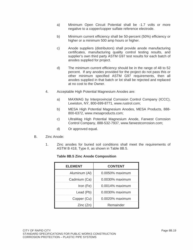
1. Zinc anodes for buried soil conditions shall meet the requirements of ASTM B 418, Type II, as shown in Table 8B.5.
Table 8B.5 Zinc Anode Composition
ELEMENT CONTENT
Aluminum (Al) 0.0050% maximum
Cadmium (Ca) 0.0030% maximum
Iron (Fe) 0.0014% maximum
Lead (Pb) 0.0030% maximum
Copper (Cu) 0.0020% maximum
Zinc (Zn) Remainder

CITY OF RAPID CITY Page 8B.20STANDARD SPECIFICATIONS FOR PUBLIC WORKS CONSTRUCTION CORROSION PROTECTION – PLASTIC PIPE SYSTEMS
2. Prepackaged Zinc Anode Dimensions
a) The anode size and weight may differ slightly because of variations in casting and mold shapes, but shall be the manufacturer’s standard and should approximate the characteristics provided in Table 8B.6.
Table 8B.6 Zinc Anode Dimension Characteristics
BARE ANODE SIZE 18 POUND ANODE 30 POUND ANODE
Shape ZUR-18 ZUR-30
Bare Anode Nominal Dimensions
1.4 inches by 36 inches long minimum
2 inches by 30 inches long minimum
Nominal Package Dimensions
5 inch diameter by 42 inches long minimum
5 inches by 38 inches long minimum
Packaged Weight 70 pounds minimum 70 pounds minimum
C. Prepackaged Galvanic Anode General Requirements:
1. Anode Wire: Supply each anode with No. 12 AWG stranded copper wire with TW, THWN, THHN or HMWPE TW, THWN, THHN or HMWPE insulation, 10 feet long minimum.
a) Provide longer anode leads as required for test stations to extend splice free from anode to test station location.
1) Lead wire shall be coiled and bound.
2. Wire-to-Anode Connection: The anode connection shall be stronger than the wire. The galvanic anode material shall be cast around a galvanized steel wire, strap, or pipe core. The anode lead wire connection to the steel core shall be silver-soldered (45% silver) by the manufacturer's standard process and be stronger than the wire. Connection of lead wire to anode shall be electrically insulated with manufacturer's standard waterproof epoxy or electrical potting compound type insulation.
3. Prepackaged Anode Backfill: Backfill shall have a grain size so that 100 percent is capable of passing through a 20-mesh screen and 50-percent will be retained by a 100-mesh screen. The backfill mixture shall be thoroughly mixed and firmly packaged around the galvanic anode within the cloth bag or cardboard tube by means of adequate vibration. The complete packaged galvanic anode shall weigh a minimum of 2.0 times the bare anode weight. The quantity of backfill shall be sufficient to cover all surfaces of the anode to a depth of 1-inch.
4. Packaging and Shipping: Bare anodes shall be centered in cotton bag filled with specified backfill. Provide anode packaged in and shipped and

CITY OF RAPID CITY Page 8B.21STANDARD SPECIFICATIONS FOR PUBLIC WORKS CONSTRUCTION CORROSION PROTECTION – PLASTIC PIPE SYSTEMS
stored in waterproof plastic or heavy multi-walled paper bag of sufficient thickness to protect the anode, wire, backfill, and cloth bag.
5. Compliance Statement: Furnish an independent laboratory analysis certifying that all anode and backfill material supplied meets the requirements of this Specification and specified laboratory testing.
6. Field Verification: At Engineer’s option, a galvanic anode may be selected at random for Contractor to provide an independent laboratory analysis on to demonstrate that both anode and backfill material supplied meets the requirements of this Specification.
7. Prepackaged Galvanic Anode Backfill Composition is provided in Table 8B.7.
Table 8B.7 Prepackaged Galvanic Anode Backfill Composition
ELEMENT CONTENT
Ground Hydrated Gypsum 75 Percent
Powdered Wyoming Bentonite 20 Percent
Anhydrous Sodium Sulfate 5 Percent
2.09 CATHODIC PROTECTION TEST STATIONS
A. Flush Mounted Test Stations
1. Flush mounted test stations shall be standard unless specifically indicated on the plans.
2. Test Box: Traffic H-10 load rated concrete body cast with a cast iron ring, with a minimum weight of 55 pounds and minimum dimensions of 10-inch inside diameter and 12-inches long.
a) Furnish with locking metallic ring extensions as required to penetrate concrete or pavement surfaces by 4-inches minimum.
b) Furnish with a minimum 12-pound cast iron lid with the letters "TS" or words “CP Test”, "Test Station" or similar words cast into the lid.
c) Test Boxes shall be:
1) Model 3RT Traffic Valve Box by Brooks Products, www.brooksproducts.com;
2) Model G3 Traffic Valve Box by Christy Concrete Products, www.oldcastleprecast.com;

CITY OF RAPID CITY Page 8B.22STANDARD SPECIFICATIONS FOR PUBLIC WORKS CONSTRUCTION CORROSION PROTECTION – PLASTIC PIPE SYSTEMS
3) Or approved equal.
3. Terminal Block: Plastic or glass-reinforced, 1/4-inch thick laminate terminal board with minimum dimensions of 3-inches by 4-inches.
a) Furnish terminal block with a minimum of seven (7) terminals. Terminal nuts and studs shall be 1/4-inch with double nuts for securing the studs to the terminal board.
b) Terminal nuts, studs, flat and lock washers shall be nickel- plated brass, bronze, or Series 300 stainless steel.
c) Terminal board shall not be connected to flush test station cap or be constructed in a manner that will accidently allow wires to be shorted together through terminal board.
d) Manufactured seven terminal test boards shall be:
1) CP Test NM-7 by Bingham & Taylor ;
2) Flush Fink 7 by COTT Manufacturing;
3) Or approved equal.
B. Shunts:
1. Shunts for test stations shall be:
a) Holloway Type RS 0.01 ohm manganin wire shunt with 6 amp capacity by Holloway Shunts;
b) Yellow CP Shunt (0.01-ohm shunt with 8 amp capacity) by M.C. Miller Company;
c) Yellow CP Shunt (0.01-ohm shunt with 8 amp capacity) by COTT Manufacturing;
d) Or approved equal.
2.10 MISCELLANEOUS REFERENCE MONITORING EQUIPMENT AND MATERIALS
A. Reference electrodes shall only be used at locations specifically indicated in the plans or as directed by the Engineer.
B. Prepackaged Copper/Copper Sulfate (CU/CUSO4) Reference Electrodes:
1. Permanent reference electrode for buried piping locations shall be a copper/copper sulfate reference electrode. Reference electrode dimensions shall be approximately 1.5-inches in diameter by 6-inches long. Reference electrode shall be suitable for permanent installation and designed for a 15-year minimum life expectancy with an accuracy of plus or minus 5-millivolts.

CITY OF RAPID CITY Page 8B.23STANDARD SPECIFICATIONS FOR PUBLIC WORKS CONSTRUCTION CORROSION PROTECTION – PLASTIC PIPE SYSTEMS
2. Electrode manufacturer shall warrant electrode for 15-year design life and provide both labor and material replacement, if electrode becomes unstable by more than 20 millivolts during design life.
3. Electrodes shall be supplied prepackaged in a permeable cloth bag containing manufacturer's special low-resistivity backfill mixture formulated to retain moisture and maintain electrode stability. Outside dimensions of electrode package shall be approximately 6-inches in diameter by 14-inches long.
4. Supply electrode with a lead wire attached and electrically insulated with the manufacturer's standard connection. The connection shall be stronger than the wire. Lead wire shall be single conductor No. 14 AWG or larger stranded copper wire insulated as specified under WIRE, this section. Lead wire shall be of sufficient length (minimum 50’) or longer as required to reach splice free from reference electrode to test station. Lead wire shall be coiled and bound.
5. Package cloth bag with reference electrode in and shipped and stored in waterproof plastic or heavy paper bag of sufficient mil thickness to protect the electrode, wire, backfill, and cloth bag.
6. Acceptable CU/CUSO4 reference electrodes can be obtained from:
a) FWCC Series SP-150 by Farwest Corrosion Control Company;
b) STAPERM Model CU-1-UGPC by GMC Electrical, Inc.;
c) Model UL CUG LongLife Reference Electrode by Electrochemical Devices, Inc.;
d) Or approved equal.
C. Plastic Reference Monitoring Pipe shall be a three-inch (3”) minimum diameter Schedule 40 PVC plastic pipe with a threaded pipe cap provided at test stations as shown on the Drawings or called out in the test station schedule. Plastic reference monitoring pipe at flush test stations shall not require a threaded cap.
2.11 CONDUIT, LOCKNUTS, AND STRAPS
A. The minimum conduit size shall be 1-inch diameter unless otherwise indicated on Drawings or specified.
B. Use intermediate metal conduit, including couplings, elbows, nipples, and other fittings, hot-dipped galvanized and meeting the requirements of UL and the NEC.
1. Do not use setscrew type couplings, elbows, and nipples unless approved by the Engineer.
C. Heavy wall rigid PVC conduit shall be Schedule 40, UL listed for concrete-encasement, underground direct burial, concealed and direct sunlight exposed use.
CITY OF RAPID CITY Page 8B.24STANDARD SPECIFICATIONS FOR PUBLIC WORKS CONSTRUCTION CORROSION PROTECTION – PLASTIC PIPE SYSTEMS
1. Use conduits, couplings, elbows, nipples, and other fittings meeting the requirements of NEMA TC and TC 3, Federal Specification W-C-1094, UL, NEC, and ASTM specified tests for the intended use.
D. Flexible metal conduit shall be UL listed, liquid-tight flexible metal conduit consisting of galvanized steel flexible conduit covered with an extruded PVC jacket and terminated with nylon bushings or bushings with steel or malleable iron body and insulated throat and sealing O-ring.
E. Locknuts, two-hole straps, and other miscellaneous hardware shall be galvanized steel.
1. Galvanized items shall be hot-dipped galvanized in accordance with ASTM A153.
2. Galvanized hardware shall not be used underground or in immersion service.
F. Conduit bushings shall be threaded plastic or plastic-throated galvanized steel fittings.
2.12 WIRE CONNECTIONS AND SPLICE MATERIALS
A. Compression Connectors:
1. Compression connectors for in-line, multi-splices, and tap splices shall be "C" taps made of conductive wrought copper, sized to fit the wires being spliced.
2. Compression connectors shall be applied with the crimp tool and die recommended by the manufacturer for the wire and tap connector size.
3. Acceptable Type "YC" wire compression connectors as manufactured by
a) Burndy, LLC;
b) Thomas and Betts;
c) Or approved equal.
4. Inline “butt” type wire splice connectors or wire nuts are NOT acceptable.
5. Split bolts are acceptable only if silver soldered after a physical connection is made and both the wires are equal to or smaller than No. 10 AWG size.
6. Silver Brazing Alloy:
a) Brazing Alloy with minimum 15 percent silver content, 1185° to 1300˚ F melting range.
CITY OF RAPID CITY Page 8B.25STANDARD SPECIFICATIONS FOR PUBLIC WORKS CONSTRUCTION CORROSION PROTECTION – PLASTIC PIPE SYSTEMS
b) Provide suitable silver brazing alloy and flux recommended by manufacturer for materials being connected (i.e. copper to stainless steel, copper to steel, and/or copper to copper, etc.).
B. Splices shall be made with suitably sized copper compression connectors and insulated with either a hand tape system, with a specially formulated splicing kit, or with an epoxy splice kit depending on wire size.
1. Smaller wires (equal to or smaller than No. 8 AWG) can be repaired with tape, or insulated with a specially fabricated splicing kit, or made with an approved epoxy insulated splice kits.
2. Insulation damage or splices to large cathodic protection cables (No. 4 AWG or larger) shall only be made with an approved epoxy type splice kit.
3. Electrical Splicing Tapes and Sealers: Tape for wire splice insulation shall be UL and CSA approved, cold and weather resistant, highly elastic, with a high dielectric strength and highly resistant to sun, water, oil, acids, alkalies, and corrosive chemicals.
4. Tapes and electrical sealers shall be suitable for moist or wet environments and may include the following:
a) Rubber High Voltage Electrical Tape: Linerless 30 mil rubber high voltage splicing tape suitable for splicing cables through 69kV
1) Scotch Professional Grade Linerless Rubber Splicing Tape 130C by 3M Products;
2) Plymouth L969 Plyvolt Linerless EPR High Voltage Tape by Plymouth Bishop;
3) Or approved equal.
b) High Voltage Vinyl Electrical Tape: All weather, minimum 7 mil thick, vinyl electrical tape suitable for cable splices up to 600 volts
1) Scotch Super 33+ Vinyl Electrical Tape as 3M Products;
2) Plymouth Premium 111 Black Vinyl Plastic Electrical Tape by Plymouth Bishop;
3) Or approved equal.
c) Filler Tapes: Low voltage rubber filler tapes or putties that can be wrapped, stretched or molded around irregular shapes for quick, smooth insulation build-up to insulate connections up to 600 volts for topcoating with vinyl electrical tapes
1) Scotchfill by 3M Products;
2) Plymouth 125 Electrical Filler Tape by Plymouth Bishop;

CITY OF RAPID CITY Page 8B.26STANDARD SPECIFICATIONS FOR PUBLIC WORKS CONSTRUCTION CORROSION PROTECTION – PLASTIC PIPE SYSTEMS
3) Or approved equal.
d) Electrical Coating Sealer: Electrical coating for sealing tape insulation on splices in severe conditions, suitable for direct burial, direct water immersion, and above grade applications
1) Scotchkote Electrical Coating by 3M Company;
2) Or approved equal.
5. Specially formulated splicing kit shall consist of an elastomeric insulating compound that seals and waterproofs connection area with a resin-impregnated, moisture-cured fabric bandage shell such as Royston SpliceRight Splicing Kit available from Chase Industries.
6. Epoxy Splice Kits: Epoxy splice kit shall be type suitable for abovegrade and buried applications and rated for non-shielded cables up to 5 kV and multi-conductor cables through 1,000 volts.
a) Splice kit shall consist of snap together plastic mold sized to fit around splice, funnels, tape for sealing ends of mold, and two-part epoxy resin in a single pouch for mixing.
b) Epoxy resin shall be electrical insulating low viscosity type that will harden (cure) quickly with time.
c) In-Line type splice insulating kit for insulation repair shall be epoxy resin, 3M Company Scotchcast Series 82; Plymouth Bishop Plycast Splicing Kit 2638; or approved equal.
d) Wye type splice insulating kit for insulation repair shall be epoxy resin, 3M Company Scotchcast Series 90B1; Plymouth Bishop Plycast Splicing Kit 2636; or approved equal.
C. Terminal and Connection Coating and Electrical Sealers:
1. Electrical Insulating Spray: Electrical insulating spray for sealing tape insulation on splices, or on terminals to minimize external corrosion;
a) Scotch 1601 Insulating Spray by 3M Company;
b) Royston Protective Coating Product Data No. 614 Royston Laboratories;
c) Or approved equal.
2. Oxidation Inhibiting Compound: - Oxidation inhibiting compound shall be non-water soluble, non-petroleum based and suitable for aluminum, copper, steel and rubber and polyethylene type insulating materials,
a) Penetrox A-13 by Burndy Products;

CITY OF RAPID CITY Page 8B.27STANDARD SPECIFICATIONS FOR PUBLIC WORKS CONSTRUCTION CORROSION PROTECTION – PLASTIC PIPE SYSTEMS
b) Contax Inhibiting Compound Type CTB by Thomas and Betts (T&B);
c) Or approved equal.
D. Wire Connector Terminals: A ring tongue terminal or single hole solderless lug type connector shall be installed on the end of all stranded wire before connecting it to test station, terminal box, or junction box terminal studs.
1. Wire connector terminals shall be sized to fit wire and stud size and be suitable for use with copper conductors.
2. One-piece heavy duty, tin-plated copper crimp-on ring tongue terminal. Acceptable ring tongue wire connectors are manufactured by
a) Burndy LLC;
b) 3M;
c) Thomas and Betts;
d) Or approved equal.
3. Single hole seamless copper Lug-it type connector rated shall be UL listed for 600-volt service with off-set tongue suitable for wire size being terminated.
a) Acceptable No. 4 and No. 2 AWG wire single hole solderless lugs are
1) L125 by Burndy;
2) BTCO208-B2 by Thomas and Betts;
3) Or approved equal.
4. Wire forked end type terminals are NOT acceptable.
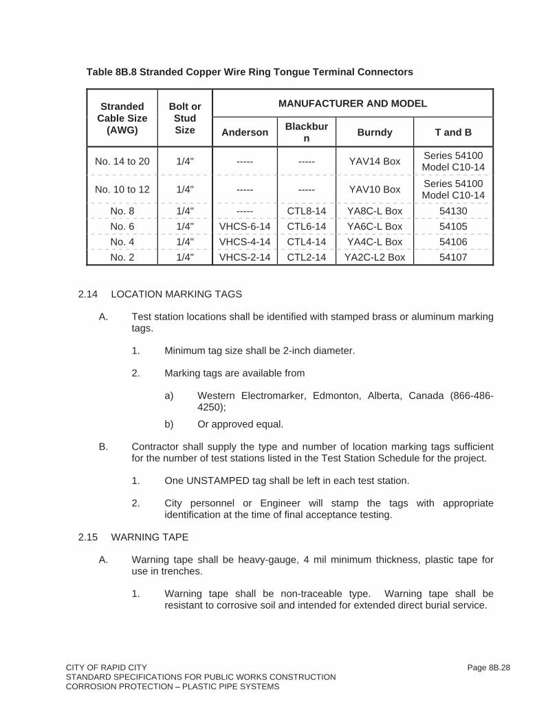
5. Acceptable one hole non-insulated copper crimp wire lug terminals sizes for ¼-inch stud sizes are listed in Table 8B.8.
E. Electrical Connectors: Hardware used in electrical connections including bolts, studs, nuts, washers, and lock-washers shall be tin or nickel plated copper, brass, bronze, or 300 series stainless steel for electrical conductivity and atmospheric corrosion resistance.
2.13 PLASTIC CONDUIT SHEATHING
A. Plastic conduit for cathodic protection cable sheathing for cathodic protection cables or wires shall be 1-inch minimum diameter Schedule 40 polyethylene (PE) or polyvinyl chloride (PVC) plastic pipe.
CITY OF RAPID CITY Page 8B.28STANDARD SPECIFICATIONS FOR PUBLIC WORKS CONSTRUCTION CORROSION PROTECTION – PLASTIC PIPE SYSTEMS
Table 8B.8 Stranded Copper Wire Ring Tongue Terminal Connectors
StrandedCable Size
(AWG)
Bolt or StudSize
MANUFACTURER AND MODEL
AndersonBlackbur
nBurndy T and B
No. 14 to 20 1/4" ----- ----- YAV14 Box Series 54100 Model C10-14
No. 10 to 12 1/4" ----- ----- YAV10 Box Series 54100 Model C10-14
No. 8 1/4" ----- CTL8-14 YA8C-L Box 54130
No. 6 1/4" VHCS-6-14 CTL6-14 YA6C-L Box 54105
No. 4 1/4" VHCS-4-14 CTL4-14 YA4C-L Box 54106
No. 2 1/4" VHCS-2-14 CTL2-14 YA2C-L2 Box 54107
2.14 LOCATION MARKING TAGS
A. Test station locations shall be identified with stamped brass or aluminum marking tags.
1. Minimum tag size shall be 2-inch diameter.
2. Marking tags are available from
a) Western Electromarker, Edmonton, Alberta, Canada (866-486-4250);
b) Or approved equal.
B. Contractor shall supply the type and number of location marking tags sufficient for the number of test stations listed in the Test Station Schedule for the project.
1. One UNSTAMPED tag shall be left in each test station.
2. City personnel or Engineer will stamp the tags with appropriate identification at the time of final acceptance testing.
2.15 WARNING TAPE
A. Warning tape shall be heavy-gauge, 4 mil minimum thickness, plastic tape for use in trenches.
1. Warning tape shall be non-traceable type. Warning tape shall be resistant to corrosive soil and intended for extended direct burial service.

CITY OF RAPID CITY Page 8B.29STANDARD SPECIFICATIONS FOR PUBLIC WORKS CONSTRUCTION CORROSION PROTECTION – PLASTIC PIPE SYSTEMS
2. Tape shall meet A.P.W.A. national color code and shall be imprinted with an appropriate legend to define the type of utility. Tape shall be labeled with bold black letters for full length of tape.
3. Warning tape for buried cathodic protection cables and conduits shall be yellow and labeled "CAUTION: CABLES BURIED BELOW" and a minimum of 3-inch width.
4. Acceptable products are available from
a) ITT Blackburn;
b) Allen Systems, Inc.;
c) Reef Industries;
d) Or approved equal.
2.16 TRACER WIRE
A. Tracer Wire:
1. Tracer Wire
a) No. 10 AWG wire for tracer wire may be single-conductor, stranded copper wire with 600-volt, TW, THWN, THHN or HMWPE insulation.
b) No. 10 AWG wire for tracer wire may be a hard-drawn, copper-clad steel conductor wire with a 45-mil high density high molecular weight polyethylene (HDPE) insulation.
1) Acceptable bi-metallic tracer wire Pro-Trace (HDD-CCS PE45) as manufactured by Pro-Line Safety Products;
2) Or approved equal.
2. Tracer wire will only be required for non-metallic pipe sections.
3. Tracer wire insulation shall be resistant to corrosive soil and intended for extended direct burial service.
4. Tracer wire color and tape markings shall be in accordance with other sections of this Specification.
5. Tape for attachment of tracer wire to pipe shall be 1-inch minimum width polyethylene tape intended for direct burial service.
6. Tracer Wire Splices
a) Compression connectors for in-line, multi-splices, and tap splices shall be "C" taps made of conductive wrought copper, sized to fit

CITY OF RAPID CITY Page 8B.30STANDARD SPECIFICATIONS FOR PUBLIC WORKS CONSTRUCTION CORROSION PROTECTION – PLASTIC PIPE SYSTEMS
the wires being spliced in accordance with “Wire Connections and Splice Materials” this section.
b) Acceptable Type "YC" wire compression connectors as manufactured by
1) Burndy LLC;
2) T and B;
3) Or approved equal.
4) Wire compression connectors shall be supplied with tape or epoxy resin type splice insulation kits.
c) Electrical Spring Connector (Wire Nut) Pigtail Wire Type Connectors with silicone gel insulation filled resin tube.
1) The electrical spring connector shall consist of a steel spring, metal shell, with a flame retardant PVC insulator outer covering.
2) The plastic tube assembly shall consist of a polypropylene tube with locking fingers to hold the electrical spring connector in the bottom portion of the tube and a plastic cap.
3) The tube shall be prefilled with non-hardening silicone electrical insulating gel sealant.
4) The electrical spring connector and plastic tube assembly shall be UL listed and CS Certified for 600 volts direct bury and submersible applications.
5) The electrical spring connector is suitable for copper wires only and shall be sized to fit three No. 10 AWG tracer wires.
6) Suitable tracer wire splice kits shall be 3M Direct Bury Splice Kit (DBR-6) or approved equal.
d) Compression Connectors or split bolts with silver solder and specially formulated splicing kit shall consist of an elastomeric insulating compound that seals and waterproofs connection area with a resin-impregnated, moisture-cured fabric bandage shell
1) Royston SpliceRight Splicing Kit available from Chase Industries or approved equal.
B. Tracer Wire Access Boxes:
1. Flush Mounted Tracer Wire Access Terminal Box:

CITY OF RAPID CITY Page 8B.31STANDARD SPECIFICATIONS FOR PUBLIC WORKS CONSTRUCTION CORROSION PROTECTION – PLASTIC PIPE SYSTEMS
a) Flush mounted tracer wire access terminal boxes shall be standard unless specifically indicated on the plans.
b) Plastic flush terminal box body (18” long shaft, 4” diameter minimum size) with cast iron collar and lockable cast iron lid, suitable for traffic conditions.
1) Minimum four (4) wire non-conductive terminal board with ¼-inch diameter stainless steel, nickel-plated brass, or bronze hardware for wire terminations.
2) Terminal board shall not be connected to flush tracer wire access box cap or be constructed in a manner that will accidently allow wires to be shorted together through terminal board.
c) Acceptable flush mounted tracer wire access boxes are:
1) Model No. P445 DT Test 4” Shaft Cathodic Protection Test Boxes by Bingham and Taylor;
2) Model NM-7 5” ID 18” Shaft Cathodic Protection Test Station by C.P. Test Services – Valvco, Inc;
3) Model T4 4” ID 18” Shaft Cathodic Test Stations by Handley Industries;
4) Model TWAB4PT 4” Tracer Wire Access Box by Drainage and Water Solutions, Inc.
5) Or approved Equal.
2.17 INSULATING JOINTS
A. General:
1. Insulating joints shall be dielectric unions, flanges, or couplings. The complete assembly shall have an ANSI rating equal to or higher than that of the joint and pipeline. All materials shall be resistant for the intended exposure, operating temperatures, and products in the pipeline.
2. No size restrictions for monolithic type insulators in buried, submerged or abovegrade locations.
3. No size restrictions for insulated flange or insulated couplings in abovegrade or vault type locations.
B. Flange Insulating Kits for Flanges and Restrained Rod Harness Sets:
1. Gaskets:
a) Low Pressure (Less than 150 psi) or Small Pipe Diameter (Less than 22-inch) - Provide full-face Type E with O-ring seal, style as

CITY OF RAPID CITY Page 8B.32STANDARD SPECIFICATIONS FOR PUBLIC WORKS CONSTRUCTION CORROSION PROTECTION – PLASTIC PIPE SYSTEMS
recommended by manufacturer for flange face type. The 1/8-inch minimum thick flanged gasket shall be supplemented with a neoprene facing on each side to accomplish a seal. Sealing element shall be designed so as to seal either flat, raised face, or RTJ flanges.
b) High Pressure (150 psi or greater) or Large Pipe Diameter (22-inch or larger) - Provide full-face Type E with O-ring seal, style as recommended by manufacturer for flange face type. The 1/8-inch minimum thick flanged gasket shall be supplemented with a Nitrile (240 degree maximum operating temperature) O-ring seal and a phenolic or G-10 (Pyrox) retainer facing on each side to accomplish a seal. Sealing element shall be designed so as to seal either flat, raised face, or RTJ flanges.
2. Insulating Sleeves: Individual full-length fiberglass reinforced epoxy, NEMA G-10 Grade material (Glass Reinforced Epoxy, Pyrox) or NEMA G-11 Grade material (Glass Reinforced Epoxy). Tube shall be 1/32-inch thick and extend ½ way into both of the inner steel washers next to the flange. Sleeve shall be a length so as to provide a small air gap between sleeve and nut when flange is tightened down in accordance with the manufacturer’s recommendations.
3. Insulating Washers: Individual high-strength fiberglass reinforced epoxy NEMA G-10 Grade material (Glass Reinforced Epoxy, Pyrox) or NEMA G-11 Grade material (Glass Reinforced Epoxy). Size shall be 1/8-inch thick, standard SAE washer dimension.
4. Steel or Stainless Steel Washers: Plated, hot-rolled steel, Minimum 1/8-inch thick If in area where stainless steel bolts and nuts required, provide Series 300 stainless steel materials or coated washers.
a) Provide two washers per bolt for flange diameters less than 36-inch diameter.
5. Flange Holes and Fasteners (Bolting)
a) For steel pipe flange, oversize bolt holes as recommended by insulated sleeve manufacturer. For ductile iron provide standard bolt hole size as recommended by sleeve manufacturer.
b) Fasteners in accordance with AWWA C207 for steel and AWWA C110 for ductile iron and the following:
c) Minimum bolt length shall be a minimum 1/8-inch to ¼-inch longer (before torquing or tightening down) than the sum of all of the materials being jointed together. This would include but not be limited to the maximum thicknesses of the mating flanges surfaces, the sealing gasket, the insulating and metal washer thicknesses, and the depth of the nut.

CITY OF RAPID CITY Page 8B.33STANDARD SPECIFICATIONS FOR PUBLIC WORKS CONSTRUCTION CORROSION PROTECTION – PLASTIC PIPE SYSTEMS
d) Provide bolts with full thread cut lengths or threaded rod as required to meet inside diameter dimension requirements of insulating sleeves. Insulated sleeves may not fit over unthreaded portions of the bolt body.
e) Coordinate bolt length and diameter with flange, bolt, and insulating sleeve manufacturers.
6. Provide Single Insulating Washer Set Kits for Buried Applications.
7. Provide Double Insulating Washer Set Kits for Above Grade Applications.
8. Acceptable flange insulating kits are available from:
a) Trojan Sealing Insulating Gaskets by Advance Products and Systems, Inc., Lafayette, LA (800-335-6009), www.apsonline.com;
b) Type E Jock by Central Plastics Co., Shawnee, OK (800-654-3872), www.centralplastics.com;
c) Low Pressure Linebacker Type E Sealing Gasket and High Pressure GasketSeal Type E Sealing Gasket by GPT Industries (formerly Pacific Seal and Insulator, Inc. (PSI) and Pikotek) Houston, TX. (800-423-2410), www.gptindustries.com;
d) Or approved equal.
C. Flexible Insulated Couplings:
1. Insulating Couplings shall meet AWWA C219 Standard for Bolted, Sleeve-Type Couplings for Plain-End Pipe. The coupling type, size, and clearance shall be style intended by coupling manufacturer to be utilized with two insulating boots (sleeves, bands, etc.) with a small lip that fits over pipe end to keep pipe separated.
a) Insulated couplings shall be factory provided by coupling manufacturer and not be made with field conversion kits.
2. Coupling Coating and Linings: Insulated fittings shall be steel and externally coated and lined with factory epoxy coating internally and externally in accordance with AWWA C210, AWWA C213, or AWWA C550.
a) Minimum surface preparation shall be white metal blast (SSPC SP-5) for internal surfaces and near white blast (SSPC SP-10) or better for external surfaces.
b) Liquid epoxy coating shall be a minimum of two coats for 14 MDFT.
c) Fusion bonded epoxy coating shall be a minimum of 10 MDFT.
d) Provide repair kits for epoxy-coated materials.

CITY OF RAPID CITY Page 8B.34STANDARD SPECIFICATIONS FOR PUBLIC WORKS CONSTRUCTION CORROSION PROTECTION – PLASTIC PIPE SYSTEMS
e) Provide a manufacturing affidavit or certification that all coating furnished complies with AWWA standards and that all AWWA standard’s inspection and tests have been completed.
3. Buried, submerged, or immersed insulating couplings bolts, nuts, and washers shall either be Series 300 stainless steel or fusion bonded steel coupling bolts, nuts, and washers per requirements of this specification. Corrten bolts are not acceptable for buried, submerged, or immersed fitting or piping locations.
4. Insulating boots shall be type and thickness as recommended by coupling manufacturer for intended service including products carried and pipe temperature. The insulating boots shall be factory fabricated and provided by coupling manufacturer. Insulating boots shall be size and type that do not interfere with correct installation and operation of the coupling.
a) Two insulating boots shall be provided for each coupling. Insulating boot shall be a one piece type and have an insulating shape with a lip or edge that fits over the end of the pipe. Boot shall be long enough to extend past end of coupling assembly body and be visible when coupling is assembled.
b) Insulating boot material shall be neoprene, nitrile, or EPDM or approved equal per coupling manufacturer’s recommendation depending on pipe size and type of service.
c) Minimum insulating boot thickness shall be:
1) 1/8-inch for pipe up to 60-inch size,
5. Insulated couplings at restrained joints shall be provided with the necessary supplemental insulated restrained joint harness assemblies as described below.
a) The use of field conversion kits will not be allowed except to insulate the restrained joint harness assembly.
b) Insulated Flexible Coupling Restrained Harness Assembly: Where shown on the Drawings and/or as required and specified provide insulated restraint/harness assembly at insulated couplings on metallic pipelines. Harness bolts shall be of sufficient length, with harness lugs placed so that coupling can be slipped at least in one direction to clear joint.
c) Provide an insulating flange conversion kit consisting of individual one-piece flange insulating sleeves and insulating washers to electrically isolate restraint harnessing assembly on both ends of harness rod.
CITY OF RAPID CITY Page 8B.35STANDARD SPECIFICATIONS FOR PUBLIC WORKS CONSTRUCTION CORROSION PROTECTION – PLASTIC PIPE SYSTEMS
1) Insulating sleeves shall be individual full-length 1/32-inch thick fiberglass reinforced epoxy, NEMA G-10 Grade material (Glass Reinforced Epoxy, Pyrox) sleeves of sufficient length to extend completely through harness lug assembly.
2) Insulating washers shall be 1/8-inch thick individual high-strength fiberglass reinforced epoxy NEMA G-10 Grade material (Glass Reinforced Epoxy, Pyrox) with a metallic washer at standard SAE washer dimension.
3) G-10 One-Piece Sleeve and Washer from PSI;
4) Or approved equal.
d) Harness lugs and harness bolts shall be sized as required to allow easy installation of insulating sleeves.
1) Harness assembly rods and bolts shall be stainless steel (Series 300) for buried or submerged locations, fusion bonded epoxy coated for dry abovegrade conditions,
2) Individual rods or entire assemble shall be heat shrink coated, coated with a 100-percent moisture cure epoxy repair coating at 20-mils,
3) Petrolatum tape coated after assembly and insulator testing,
4) Bitumastic type coatings are not an acceptable option for coating of restraining rods.
6. Insulating Flexible Couplings shall be F x E Type 1 insulated style that is electrically insulating type with two insulated boots (or bands) to be installed on the pipe under the coupling. Acceptable insulating flexible couplings are:
a) Series 216 by Baker Couplings, Los Angeles, CA (800-247-7164);
b) Dresser Style 39 by Dresser Industries, Inc., Bradford, PA (814-368-3131);
c) Style 416 by Smith-Blair, Inc., Texarkana, AR (501-773-5127);
d) Depend-O-Lok by Victaulic, Inc., Atlanta, GA (800-841-6624);
e) Series 200 couplings by Baker Coupling Company, Los Angeles (323-583-3444);
f) Or approved equal.
7. All buried or submerged flexible coupling fasteners shall be Series 300 stainless steel.

CITY OF RAPID CITY Page 8B.36STANDARD SPECIFICATIONS FOR PUBLIC WORKS CONSTRUCTION CORROSION PROTECTION – PLASTIC PIPE SYSTEMS
D. Copper Service Line Insulators:
1. Insulated service fittings shall consist of brass union body that encapsulates a nylon insulator specially designed to provide electrical isolation for this type of intended use:
a) Insulated corporation ball valves, insulated curb ball valves, and service line insulators shall be provided to insulate copper or metallic service lines.
2. Acceptable service line insulators are available from:
a) Mueller Co., Decatur, IL (800-423-1323);
b) Or approved equal.
3. Consult manufacturer for model number and installation procedures for each application.
2.18 INSULATING FLOOR AND WALL SLEEVES AND MODULAR SEALS
A. Wall Sleeves: Pipe wall sleeves or cored openings shall be provided at all wall and floor locations in accordance with pipe and sleeve manufacturer’s recommendations.
1. The pipe wall sleeves shall be of sufficient thickness to resist any deformation. The pipe wall sleeves shall be round with a maximum +/- 1/8-inch variation in diameter allowed. The wall sleeve shall be a minimum wall thickness of 0.375-inch or standard wall thickness. The minimum width of the wall sleeve shall be per the modular seal manufacturer’s recommendations to meet minimum width requirements based on seal type and pipe diameter and weight.
2. Pipe wall sleeves shall be provided with a minimum three-inch (3”) water stop collar that evenly contacts the wall or floor opening all the way around for a minimum length of one-inch (1”) or more if recommended by the sleeve manufacturer. The water stop (collar) shall be of the same type of material as the wall sleeve. The wall sleeve shall have a smooth continuous weld with no welding slag or rough or high welds. The water stop collar shall be continuously welded on both sides of the collar for the entire circumference of the wall sleeve.
3. The wall sleeve and the water stop collar shall be positioned such that it is located in the center of the structure wall or floor, when the wall sleeve is positioned in place. Steel wall sleeves and water stop collars shall be coated. The wall or floor penetration diameter and width shall be sized sufficiently to allow correct installation of the wall sleeve and water stop.
4. Wall penetrations and wall sleeves types and sizes shall be coordinated with sleeve manufacturer, modular seal manufacturer, and pipe

CITY OF RAPID CITY Page 8B.37STANDARD SPECIFICATIONS FOR PUBLIC WORKS CONSTRUCTION CORROSION PROTECTION – PLASTIC PIPE SYSTEMS
manufacturer to provide proper type of opening to provide a liquid tight connection.
5. Wall pipe sleeves placed around pipe and grouted in place in accordance with sleeve and pipe manufacturer’s recommendations are an acceptable method of wall openings.
6. Coordinate wall sleeve type, model, size, and location with modular seal and pipe manufacturers.
7. Prefabricated Coated Steel Pipe Wall Sleeves shall be preprimed or coated minimum Schedule 40 wall thickness with standard 12-inch length, centered type with a minimum 3” water stop sized to fit pipe size.
a) Depending on location, wall size, and pipe size prefabricated steel pipe wall sleeves are available from
1) Model WS Steel Wall Sleeves (coated steel with a welded water stop) by GPT Industries (formerly PSI), Houston, TX (800-423-2410);
2) Model SWS (primed steel with a welded water stop), or Model GWS (steel with a welded water stop and Galvo-Plast coating) by Advance Products and Systems, Inc., Lafayette, LA (800-335-6009);
3) Or approved equal.
b) Consult manufacturer for specific model required.
B. Insulating Wall or Floor Modular Seals. Insulating wall and floor seals shall be adjustable modular mechanical type seals able to provide a positive seal (liquid tight) and long lasting electrical insulation for wall or floor penetrations for pressures up to 40-feet of static head. Coordinate with and provide pipe and modular seal manufacturer's recommended modular seal type and size for pipe type, pipe diameter, casing or hole opening size, environmental exposure, operating temperature, and intended installation conditions.
1. The modular seals shall consist of synthetic rubber bolted links, heavy duty reinforced high density nylon polymer plastic pressure plates, and Type 316 stainless steel hardware (bolts, nuts, washers, etc.) for adjustment. The modular seals shall be manufactured at a plant with a current ISO-9001 registration which shall be included as part of the submittal.
2. The rubber links shall consist of interlocking synthetic rubber links shaped to continuously fill the annular space between the pipe and the opening. The individual links shall be colored and permanently identified with the manufacturer’s name and model number. The link shall be sized per the manufacturer’s recommendations. The links shall have the following properties per ASTM standards for standard type applications (-40
CITY OF RAPID CITY Page 8B.38STANDARD SPECIFICATIONS FOR PUBLIC WORKS CONSTRUCTION CORROSION PROTECTION – PLASTIC PIPE SYSTEMS
degrees to 250 degrees F) Model C EPDM = ASTM D2000 M3 BA510 Black.
3. The pressure plates shall be molded glass reinforced nylon polymer with an integrally molded compression assist boss on pressure plated top side (bolt entry side). The pressure plate shall incorporate an integral recess (“Hex Nut Interlock”) to accommodate commercially available fasteners. The individual pressure plates shall be colored and permanently identified with the manufacturer’s name. The pressure plate shall be sized per the manufacturer’s recommendations. The links shall have the following properties per ASTM standards for standard type applications:
a) ASTM D-256 Izod Impact = Minimum 2.05 foot-pound/inch
b) ASTM D-790 Flexure Strength at Yield = Minimum 30,750 PSI
c) ASTM D-790 Flexure Modulus = Minimum 1,124,000 PSI
d) ASTM D-638 Elongation Break = Minimum 11.07%
e) ASTM D-792 Specific Gravity = Minimum 1.38
4. The modular seal hardware shall be sized according to the seal manufacturer’s recommendations depending on the size and type of modular seal. The 316 Stainless Steel hardware shall have the following properties per ASTM standards for standard type applications including ASTM F593 with an average tensile strength of a minimum 85,000 PSI.
C. Modular Wall Seals: Acceptable modular wall seal insulators for pipe diameters equal to or smaller than 24-inch diameter are:
1. Thunderline Link-Seal Model LS-300 or LS-400 by GPT Industries (formerly Pacific Seal and Insulator, Inc. PSI) Houston, TX. (800-423-2410);
2. Pipe Linx Model PL-300 or PL-400 by Calpico, Inc. South San Francisco, CA. (650-588-2241);
3. Innerlynx Model IP-300 or IP-400 by Advance Products and Systems, Inc., Lafayette, LA (800-315-6009);
4. Or approved equal.
D. Wall sleeves passing through walls of structures containing liquids shall be provided with double sets of modular wall seals to provide pipe support at the penetration and protection against leakage.
2.19 COATING AND LINING FOR FITTINGS, INCIDENTAL PIPING AND VALVES
A. Supply incidental pipe, valves, fire hydrants and fittings with linings and coatings of the same type as adjacent pipe, except where shown on the Drawings. Coat incidental pipe and fittings installed as specified in this specification section.
B. Coat and line all buried metallic (steel, ductile iron, and cast iron) valves, fittings, miscellaneous piping, and hydrants internally and externally. Supply factory

CITY OF RAPID CITY Page 8B.39STANDARD SPECIFICATIONS FOR PUBLIC WORKS CONSTRUCTION CORROSION PROTECTION – PLASTIC PIPE SYSTEMS
coated valves and fittings with linings and coatings of the same type as adjacent abovegrade pipe, except where shown on the Drawings or where coating or lining specified for buried main pipeline is not feasible for fabricated items or special pipe pieces (such as incidental metallic piping, valves, fittings, tees, flexible couplings, glands, hydrants, etc.).
1. Internal linings and coatings exposed to water shall be NSF approved for potable water service.
2. Minimum surface preparation shall be white metal blast (SSPC SP-5) for internal surfaces and near white blast (SSPC SP-10) or better for external surfaces.
3. Provide tight bonded coating and lining of pipe and fitting joints at maximum thicknesses shall be as recommended by the pipe or fitting manufacturer so as to not impair engagement of pipe or fitting joint or function of fitting.
4. All ferrous interior mounting faces/surfaces shall be prepared and shop primed with a suitable rust-inhibitive holding primer applied in accordance with this specification and the coating manufacturer’s recommendations. Holding rust-inhibitive primer shall be compatible with specified top coats. Apply per coating manufacturer's recommendations to a thickness that will not impair the clearances required for proper installation of the joint or fitting (valve, coupling, flange, etc.) operation.
5. Valve bolts, nuts, and washers, (including in valve bonnet and stuffing) box) shall be Series 300 stainless steel.
C. Ductile Iron and Cast Iron Factory Coating Surface Preparation:
1. Use SSPC SP grades as surface preparation guide only as it applies to cast iron or ductile iron in percentage cleanliness required and surface contaminants removed, not the color of the metal.
2. The abrasive blast cleaning operation shall remove the same percentage of all surface contaminants (including tightly adhered annealing scale) as the SSPC SP grade referenced.
3. The entire surface area shall be abrasive blasted. No tight rust stains shall be allowed.
4. Avoid overblasting, high nozzle velocities, and excessive blast times.
5. Cast iron and ductile iron attain a gray color when abrasive blasted due to the higher carbon content compared to steel
6. SSPC SP-10 Near White Grade is specified for cast iron or ductile iron, the degree of surface cleanliness is comparable to a near white blast for steel and requires 95 percent removal of all surface contaminants

CITY OF RAPID CITY Page 8B.40STANDARD SPECIFICATIONS FOR PUBLIC WORKS CONSTRUCTION CORROSION PROTECTION – PLASTIC PIPE SYSTEMS
including tightly adhered annealing scale. Ductile or cast iron will not be required to be near-white but will only be required to be a near-gray color.
D. At Contractor’s option, factory coat or line the incidental piping, valves, or fittings with liquid epoxy or with fusion-bonded epoxy coating in accordance with these specifications and AWWA C210, AWWA C213, AWWA C116, or AWWA C550. Coating shall meet all AWWA standard requirements and tests and this specification section.
E. Liquid Epoxy:
1. Provide factory applied liquid epoxy lining and coating in accordance with AWWA C210 and AWWA C550 and these specifications. Epoxy material shall meet the performance requirements of the referenced AWWA standards. Epoxy material shall be the product of a coating manufacturer normally engaged in production of such material and shall be for intended service conditions.
2. Coating in contact with potable water shall conform to NSF Standard 61.
3. The liquid epoxy coating shall be a two part chemically cured coating or 100-percent material. Coating shall be mixed and applied per coating manufacturer’s directions. Liquid-epoxy lining of metallic pipe and fittings shall be potable grade epoxy coating approved for potable water contact and this type of intended service.
4. Abrasive blast with material and in manner as recommended by coating manufacturer to produce surface profile depth and angular shape needed. Surface preparation shall be a minimum of SSPC SP-5 (White) for immersion service and SSPC SP10 (Near White) or better for external service.
5. Coating shall be a minimum of two or more coat system with a minimum thickness of 14 MDFT.
6. Minimum adhesion to prepared steel shall be 400 psi per ASTM D1002 or per coating manufacturer’s printed literature, which ever is higher.
7. Acceptable liquid epoxy materials for linings in contact with potable water or buried-service metallic fittings, valves, etc are
a) Carboguard as manufactured by Carboline®;
b) Bar-Rust 233H as manufactured by ICI Devoe;
c) SherPlate PW Epoxy B62 as manufactured by Sherwin-Williams;
d) PotaPox Plus Series N140 or L140 manufactured by Tnemec;
e) Or approved equal.

CITY OF RAPID CITY Page 8B.41STANDARD SPECIFICATIONS FOR PUBLIC WORKS CONSTRUCTION CORROSION PROTECTION – PLASTIC PIPE SYSTEMS
8. Acceptable liquid epoxy materials for abovegrade structures are
a) Carbothane 133 LH as manufactured by Carboline®;
b) Devthane 379 UVA Polyurethane Enamel as manufactured by ICI Devoe;
c) Hi-Solids Polyurethane Enamel B65 by Sherwin-Williams;
d) Series 1074U Endura-Shield II Aliphatic Acrylic Polyurethane;
e) Or approved equal.
9. Finish for abovegrade structures shall be high gloss with color selected by the Owner for the intended service.
F. Fusion-Bonded Epoxy:
1. Provide factory applied fusion-bonded epoxy lining and coating in accordance with AWWA C213, AWWA C116, and AWWA C550, and these specifications.
2. Fusion-bonded epoxy material shall meet the performance requirements of the referenced AWWA standards.
3. Coating in contact with potable water shall conform to NSF Standard 61.
4. Fusion-bonded epoxy material shall be the product of a coating manufacturer normally engaged in production of such resin and shall be for intended service conditions.
5. The fusion bonded epoxy coating shall be a 100-percent powder epoxy based thermosetting coating. Coating shall be applied by flocking, fluidized bed, or electrostatic method per coating manufacturer’s directions.
6. Fusion-bonded epoxy lining of metallic pipe and fittings shall be potable grade epoxy coating approved for potable water contact and this type of intended service.
7. Abrasive blast with material and in manner as recommended by coating manufacturer to produce surface profile depth and angular shape needed. Surface preparation shall be a minimum of SSPC SP-5 (White) for immersion service and SSPC SP10 (Near White) or better for external service.
8. Fusion bonded epoxy coating shall be one or two-coat system with a minimum thickness of 8 MDFT.
9. Minimum adhesion to prepared steel shall be 3,000 psi per ASTM D1002 or per coating manufacturer’s printed literature, which ever is higher.

CITY OF RAPID CITY Page 8B.42STANDARD SPECIFICATIONS FOR PUBLIC WORKS CONSTRUCTION CORROSION PROTECTION – PLASTIC PIPE SYSTEMS
10. Acceptable fusion-bonded epoxy materials are listed below:
a) Scotchkote 206N, 323 or 162 as manufactured by 3M™;
b) Nap-Gard® 7-2500 pipe coating as manufactured by DuPont;
c) Nap-Gard 7-4500 (CV Red FBE) for valves and fittings as manufactured by DuPont;
d) Valspar 1F1947T as manufactured by Valspar General Industrial;
e) Or approved equal.
G. Conduct dry film thickness measurements and 100-percent holiday inspection of all factory epoxy-coated items prior to shipment.
1. Conduct dry film thickness measurements in accordance with SSPC PA-2 with exception that the specified thickness is the absolute minimum.
2. A minimum of two dry film thickness measurements shall be completed for each fitting or appurtenance.
3. Repair all defects with approved repair material according to original coating manufacturer’s directions prior to shipment.
H. Provide field repair kits for all types of coated materials.
I. Provide exterior coating for all above-grade piping, fittings, and vent pipes with two coats of polyamide epoxy coats at a minimum 2.5 MDFT per coat (MDFTPC) and with one top coat of polyurethane enamel at a minimum 3 MDFT or with a minimum 10 MDFT fusion-bonded epoxy coating system. Minimum surface preparation shall be near-white metal blast (SSPC SP-10) for external surfaces. Color specified by Engineer.
1. Hot dipped galvanized or plastic (PVC) type vent pipes do not require epoxy/polyurethane coating system.
J. Coating for valves, fittings and fire hydrant legs shall consist of one of the following:
1. Liquid epoxy coating shall be a minimum of two coats or more for a minimum 14 MDFT coating thickness.
2. Fusion bonded epoxy coating shall be one or more coats for a minimum coating thickness of 8 MDFT.

CITY OF RAPID CITY Page 8B.43STANDARD SPECIFICATIONS FOR PUBLIC WORKS CONSTRUCTION CORROSION PROTECTION – PLASTIC PIPE SYSTEMS
3. Nylon coating shall be one or more coats for a minimum coating thickness of 10 MDFT applied in a fluidized bed.
4. Polyurethane coating shall be a minimum 40 MDFT for ductile iron valves and fire hydrant legs and stub pieces (American AVK fusion-bonded epoxy interior with polyurethane coated exterior or approved equal).
5. Maximum coating thickness shall be as recommended by fitting manufacturer so as to not impair engagement of joint or function of fitting.
K. Provide a manufacturing affidavit for all factory epoxy coated or stainless steel items that list:
1. Applicator of coating including name, address, phone number and date of Application
2. Coating Material Manufacturer and Product Designation with a product data sheet.
3. Certification that all coating furnished complies with AWWA standards and these specification requirements and that all AWWA standard’s inspection and tests have been completed and were met.
4. Certification that stainless steel items are provided as specified including name of stainless steel manufacturer and Series 300 grade provided.
L. Restraint Fitting Coating System
1. Restrained fittings (casting bodies, wedge assemblies, and related parts, etc.) shall be abrasive blasted followed by a phosphate wash, rinse, and drying pretreatment process just prior to coating.
2. Restrained fittings (casting bodies, etc.) shall be coated immediately following the pretreatment process. The coatings shall be electrostatically applied and heat cured. Acceptable casting body coating systems shall consist of:
a) A sealer prior to pretreatment drying and two coats of a thermosetting powder coating at minimum 3 to 6 MDFT.
b) Acceptable TGIC polyester powder coatings for restrained fittings (casting bodies) are
1) EBAA Iron Mega-Bond Restraint Coating System;
2) Star-Bond Coating System;
3) Or approved equal.
c) A fusion bonded epoxy coating at a minimum 8 MDFT, Romac Industries Romacote Corvel Black;

CITY OF RAPID CITY Page 8B.44STANDARD SPECIFICATIONS FOR PUBLIC WORKS CONSTRUCTION CORROSION PROTECTION – PLASTIC PIPE SYSTEMS
d) A nylon coating system at minimum 10 MDFT Romac Industries Romac Nylon Coating;
e) Or approved equal.
3. Wedge assemblies and related parts shall be coated immediately following the pretreatment process with an approved coating system consisting of either:
a) A thermoplastic flouropolymer type fastener coatings specifically designed for that type of application at a minimum 1 to 2 MDFT.
b) The thermoplastic flouropolymer coating system shall consist of two or more coats of liquid thermoset epoxy coating with heat cure following each coat.
c) Acceptable flouropolymer coatings for the wedges and wedge actuators are
1) EBAA Iron Mega-Bond Restraint Coating System;
2) Star-Bond Coating System;
3) Or approved equal.
M. A fusion bonded coating system consisting of one or more coats of fusion bonded epoxy electrostatically applied and heat cured following each coat with a total fusion bonded epoxy coating system minimum thickness of 6 MDFT.
N. Provide stainless steel materials or coat all other miscellaneous buried metallic items, (tie rods, thrust restraints, tapping saddles, harnesses, etc.). Coat tie rods and rebar when directly exposed to soil. Provide with factory applied epoxy coating, fusion bonded epoxy coating, heat shrink sleeves, or with coating recommended by coating manufacturer for buried application and approved by Engineer for intended exposure.
O. Bolts, nuts, and washers, for valves (including in valve bonnet and stuffing box) shall be Series 300 stainless steel.
P. Galvanized or black steel materials (piping, nipples, unions, fittings etc.) shall not be used in wet, immersed, or buried locations or vaults unless tight-bonded coated as specified.
2.20 FASTENERS (BOLTS, NUTS, WASHERS, ETC.)
A. All fasteners (bolts, nuts, tee bolts, and washers) type, size, and strength shall be according to this specification unless other design information is provided in the plans or detailed specifications. All nuts shall be fully seated. Nuts shall be compatible with the bolts and have a proof stress equal or greater than the tensile strength of the bolts. Minimum bolt size, lengths, and tensile shall be as designed for the application.

CITY OF RAPID CITY Page 8B.45STANDARD SPECIFICATIONS FOR PUBLIC WORKS CONSTRUCTION CORROSION PROTECTION – PLASTIC PIPE SYSTEMS
B. Coated fasteners (bolts, nuts, tee bolts, and washers) are allowed. Coated fasteners shall meet the following requirements:
1. Coated bolts shall be undersized or the nuts oversized as required to minimize damage to coatings, however, size shall still satisfy design and manufacturer's requirements for bolt strength and size in the particular application. Provide with applicator name, coating manufacturer and product number, and certification that coating was applied as specified.
2. Coated bolts, nuts, and washers for ductile iron pipe and fittings shall be low carbon weathering steel meeting the strength, physical, marking, traceability, and chemical requirements of AWWA C111 and coated with an approved fastener coating system.
3. Bolts, washers, nuts, and T-bolts shall be pretreated and coated with a thermosetting powder coating or fusion bonded epoxy type fastener coating system.
a) Thermosetting powder coatings shall be at a minimum 1 MDFT with Xylan, Type E, Flour Kote #1, or thermoplastic flouropolymer type fastener coatings specifically designed for that type of application.
b) Fusion bonded coated steel bolts, nuts, and washers, fittings, and bodies shall be coated with a minimum 6 MDFT epoxy coating per AWWA C213. Surface preparation shall be SSPC SP-10 (near white).
C. Stainless Steel Fasteners (bolts, nuts, T-bolts, washers, etc.)
1. Stainless steel bolts, tee bolts, nuts, and washers shall be Series 304 or Series 316 for the specific environment of use.
2. Stainless steel bolts and nuts shall be provided with an anti-galling lubricating compound or coated with a 1-mil fluorpolymer or equal fastener coating system to aid in preventing galling.
D. Corten® bolts are not acceptable for buried, submerged, or immersed fitting or piping locations.
E. Bolts and nuts shall be adequately labeled to provide traceability of the material and producer.
1. The identification mark shall be cast, forged or stamped on the bolt and nut. Painted markings are not acceptable.
2. The bolt and nut manufacturer shall provide information on the type of material provided and corresponding identification mark, and country of origin.

CITY OF RAPID CITY Page 8B.46STANDARD SPECIFICATIONS FOR PUBLIC WORKS CONSTRUCTION CORROSION PROTECTION – PLASTIC PIPE SYSTEMS
3. Markings and traceability requirements shall be in accordance with the Industrial Fasteners Institute and AWWA C111.
F. All bolts and nuts shall be installed according to manufacturer's requirements including the use of anti-galling lubricant compound or use of a thermosetting fluoropolymer type coating for stainless steel materials.
1. If galling or seizing of the nut and bolt occurs they shall be cut off and replaced with a new nut and bolt.
2.21 STAINLESS STEEL FABRICATION AND PASSIVATION
A. Utilize Type L grade stainless steel for all items to be welded.
B. During fabrication, handling, and installation take necessary precautions to prevent mild carbon steel impregnation of stainless steel members.
C. Utilize brushes (stainless steel, non-metallic), grinding wheels (aluminum oxide discs), and tools intended for stainless steel and not used previously for carbon steel work.
D. Degrease and clean prior to welding with non-chlorinated solvents.
E. Weld stainless steel with approved materials and techniques.
F. Clean and remove contamination, remove weld heat tint, and repassivate welds per ASTM A 380 and ASTM A967.
G. After treatment visually inspect surfaces for compliance.
H. Pack stainless steel parts and pad mild steel fork lift forks and use straps instead of metal chains to handle stainless steel parts to avoid iron contamination of stainless steel.
I. After installation, visually inspect stainless steel surfaces for evidence of iron cross contamination, rust, oil, paint, and other forms of contamination. Repair as required and reinspect.
2.22 PIPE AND FITTING FIELD COATING REPAIR MATERIALS
A. Field repair incidental pipe and fitting coatings and linings in accordance with this specification section.
B. Field repair coating shall be compatible with factory coating and linings and be approved by factory coating manufacturer for repair on their products.
C. Field Coating Repair Materials:
1. Heat Shrink Sleeve and Sleeve Repair Materials: Heat shrink sleeve repair materials shall consist of either heat shrink sleeve in tube form or

CITY OF RAPID CITY Page 8B.47STANDARD SPECIFICATIONS FOR PUBLIC WORKS CONSTRUCTION CORROSION PROTECTION – PLASTIC PIPE SYSTEMS
heat shrink patch kit depending on size and shape of repair. Acceptable heat shrink products are
a) Raychem WaterWrap sleeve or PERP Repair Patch Kit available from Tyco Adhesive (Polyken Kendall) Mansfield, MA.;
b) CANUSA Aqua-Shield Aqua-Sleeve or CANUSA CRPK Repair Patch Kit available from CANUSA, Inc., The Woodlands, TX.;
c) Or approved equal.
2. Tape: Cold-applied field repair polyethylene repair type coatings shall consist of suitable primer and minimum 35-mil thick patch/repair/joint tape with aggressive adhesive and release liner, 4 or 6-inches width. Suitable primer shall be provided with the repair coatings as recommended by the repair-coating manufacturer. Acceptable products are
a) Tapecoat H35 Gray by The TAPECOAT Company, Evanston, IL.;
b) Polyken 1027 primer and Polyken 934-35 tape by Tyco Adhesive (Polyken Kendall) Mansfield, MA.;
c) Tek-Rap 200-23 Series primer and Tek-Rap 280 tape by Tek-Rap, Inc., Houston, TX.;
d) Or approved equal.
3. Epoxy Repair Coatings: Provide 100-percent epoxy coatings that can cure under wet or dry conditions
a) A-788 Splash Zone Compound by Koppers, Pittsburgh, PA;
b) Aquata Poxy by Raven (King Adhesive Corporation), St. Louis, MO;
c) Concresive No. 1438 or No. 1170 by Adhesive Engineering Company, San Carlos, CA;
d) Protal 7125 Repair Coating by Denso North America;
e) Tnemec FC 22 Epoxoline by Tnemec Company Incorporated, Kansas City, Missouri;
f) HBE-95 WG High Build Epoxy, CANUSA-CPS, Inc., The Woodlands, TX;
g) Or approved equal.
4. Four layer petrolatum wax-tape system (AWWA C-217) intended for burial conditions.
a) Completed buried system shall consist of a minimum four layer system consisting of a primer, mastic filler, petrolatum wax tape and an outerwrap.
b) Acceptable petrolatum coating systems are

CITY OF RAPID CITY Page 8B.48STANDARD SPECIFICATIONS FOR PUBLIC WORKS CONSTRUCTION CORROSION PROTECTION – PLASTIC PIPE SYSTEMS
1) STAC Coating System by Central Plastics Company, Shawnee, OK.;
2) Denso Pipe and Fittings Petrolatum System by Denso Products, Houston, TX.;
3) No. 1 Wax-tape Coating Systems for buried locations by The Trenton Corporation, Ann Arbor, MI;
4) No. 2 Wax-tape Coating Systems for above grade and vault applications by The Trenton Corporation, Ann Arbor, MI;
5) Or approved equal.
2.23 CORROSION TEST EQUIPMENT
A. Obtain and furnish the following equipment and materials for corrosion and tracer wire functional testing. Arrange and have test equipment at project site before construction begins:
1. One Heavy Duty, Digital Multimeter, with case and test leads. Instrument shall be suitable for field conditions, be sealed to meet IP 67 waterproof and dust conditions, meet CAT IV minimum 600 volt rating, and comply with IEC and ANSI electrical safety standards. Acceptable digital multimeters are
a) Model No. 27 II or Fluke 28 II by John Fluke Mfg. Co., Inc. Everett, WA;
b) Amprobe Model HD-160C by Amprobe Test Tools ( formerly Wavetek Instruments, Beckman) Everett, WA;
c) Or approved equal.
2. Two Copper-Copper Sulfate Reference Electrodes with cone shaped tip,
a) Model 6B by Tinker and Rasor, San Gabriel, CA;
b) Model RE-5C by M C MILLER Co., Vero Beach, FL;
c) Or approved equal.
3. One 32 oz bottle of Copper-Copper Sulfate Anti-Freeze Solution as manufactured by Tinker and Rasor, San Gabriel, CA; M C MILLER Co., Vero Beach, FL; or approved equal.
4. One 3/4 pound bottle of Copper-Copper Sulfate Crystals as manufactured by Tinker and Rasor, San Gabriel, CA; M C MILLER Co., Vero Beach, FL; or approved equal.
5. The test equipment shall be stored at the project site and shall be maintained in accurate, working condition. The test equipment shall be available to Engineer and Owner for testing purposes.

CITY OF RAPID CITY Page 8B.49STANDARD SPECIFICATIONS FOR PUBLIC WORKS CONSTRUCTION CORROSION PROTECTION – PLASTIC PIPE SYSTEMS
6. For projects with a combined pipe length of two miles or more, Contractor shall obtain and furnish new equipment outlined above. At the completion of the project, the equipment shall be turned over to the Rapid City Utility Maintenance Department.
2.24 MANUFACTURER’S CERTIFICATIONS
A. Manufacturer's certifications of materials and installation are provided at the end of this specification section. Attachments A, B and C shall be completed and submitted as outlined in the attachments.
8B.3 EXECUTION
3.01 GENERAL
A. All materials and equipment associated with pipe connecting wires, joint bonding, test stations, reference electrodes, galvanic anodes, insulating joints, and casing insulators as shown and specified herein shall be furnished and installed by the Contractor.
B. Coordinate installation of the specified work as necessary such that installation of the items herein specified can be completed concurrently with pipeline installation. Test leads shall be installed only during pipe installation. Items not installed before backfilling of the pipe shall be installed at the Contractor's sole expense. Additional excavation of pipe after backfilling shall be minimized to protect pipe and coating from possible damage. Galvanic anodes shall be only installed at the same time as metallic fitting installations are being constructed.
C. Nothing included or omitted in this specification shall relieve the Contractor of the obligation of providing a complete and satisfactory pipeline that is electrically continuous, electrically isolated, and provided with a functioning cathodic protection system with test stations as specified.
D. Weather Conditions:
1. Installation of the corrosion protection system components, such as splices, bonds, and wire installation shall only be allowed when ambient temperature are above ten degrees (10°) F. (-12° C.) and rising to minimize wire and insulation damage.
2. Materials shall be stored in covered and heated storage units to maintain minimum temperatures above restricted temperature limits.
E. Do not thermite (exothermic) weld, pin braze, weld, or utilize open flame or torches in areas of flammable vapors or air borne particles, where a fire or explosion could result.
F. Install and work around abovegrade and buried AC powerlines and gas pipelines with extreme care, follow minimum separation distances per foreign company requirements and regulations. Do not work next to powerlines during times of high lightning activity.

CITY OF RAPID CITY Page 8B.50STANDARD SPECIFICATIONS FOR PUBLIC WORKS CONSTRUCTION CORROSION PROTECTION – PLASTIC PIPE SYSTEMS
G. Installations shall be completed per the National Electrical Code (NEC), and as specified in this section.
3.02 MATERIAL STORAGE AND HANDLING
A. Store materials in secure, protected location in accordance with material manufacturer’s recommendations. Store thermite weld materials, reference electrodes and prepackaged galvanic anodes off the ground and keep them dry at all times.
B. Equipment or materials damaged in shipment or in the course of installation shall be replaced. Immediately remove from site all mechanically damaged materials. Prepackaged corrosion control items shall be handled with care to prevent loss of backfill material. Do not lift, lower, or hold anodes and reference electrodes by the lead wire.
C. Do not allow reference electrodes to freeze. Store in protected area, off the ground. Utilize before expiration of shelf life .
3.03 PIPE JOINT AND FITTING BONDING
A. To form an electrically continuous pipeline and associated appurtenances the joints of all buried metallic pipe, vault, and manhole piping and all appurtenances, tees, elbows, restrained joints, valves, and fittings including hydrant and blow-off piping shall be electrically joint bonded. All joints including all bolted and restrained joints shall be joint bonded, except those joints specified to be threaded, welded, or insulated. Blow off and hydrant pipe and fittings shall also be bonded. Do NOT joint bond across insulating joints.
B. Various components of metallic fittings (thrust restraint devices, follower rings or glands, etc.) on plastic or ductile iron pipelines shall be bonded together to provide an electrically continuous fitting or appurtenance.
C. Place metallic fitting bond wires on top quadrant of pipe or fitting to bolt pattern area or where flange edges are to minimize damage to internal coating or joint materials. Bonding can be completed abovegrade prior to fitting assembly.
D. Wire connections to pipes or fittings shall be as specified under WIRE CONNECTIONS.
E. Install one insulated joint bond wire or bond strap per joint on all pipe or fittings 10 inches in diameter or smaller. Install a minimum of two or more insulated joint bond wires per joint on all pipe or fittings 12 inches in diameter or larger for redundancy.
F. Bond wire size may be No. 4 AWG on pipe sizes equal to or smaller than 15-inch diameter. Insulated joint bond wires or coated or bare copper straps may be utilized depending on joint coating type. Place bond wires on top quadrant of pipe.
G. Minimum number of bond wires or straps per pipe size is as follows:
CITY OF RAPID CITY Page 8B.51STANDARD SPECIFICATIONS FOR PUBLIC WORKS CONSTRUCTION CORROSION PROTECTION – PLASTIC PIPE SYSTEMS
H. Factory Coated or Tape Coated Pipe Joints: Use insulated stranded copper joint bond wires or insulated copper strap bonds for bell and spigot locations where heat shrink sleeves are not used.
1. Use insulated stranded copper joint bond wires or insulated strap bonds for all other locations where joints or fittings are already coated such as for factory coated bolted fittings, where a heat shrink sleeve is not specified.
I. Bond bolted restrained type joints, multiple segmented fitting sections, and metallic gland connection pieces on fittings on plastic pipe, and metallic pipe into cathodic protected metallic fittings or pipe with single No. 12 AWG stranded insulated copper wires with sleeves. Length of pigtail bond wire as required. Bond across the joint with the specified number and larger sized bonds listed above based on pipe size and material.
J. Joint bonding of cast iron soil pipe not required unless specifically shown on Drawings. Joint bonds for cast iron soil pipe and fittings and high silicon cast iron pipe and fittings shall be in accordance with the manufacturer's recommendations.
K. Bronze wedges, restrained joints, bolted or compression sleeved wires or copper straps, thrust restraints, or welded “Z” bars are NOT acceptable methods of achieving electrical continuity.
3.04 WIRE CONNECTIONS
A. The electrical connection of copper wire or copper strap to metallic (steel, cast iron, and ductile iron) surfaces shall be by the thermite weld method. Prepare surface and make connections in accordance with the thermite weld manufacturer’s recommended procedures and these specifications, which ever one is more stringent.
B. Provide adequate ventilation and safety equipment (gloves, safety glasses, etc.) and follow safety and training requirements as recommended by the thermite weld material manufacturer. Avoid contact with hot materials. Remove or protect fire hazards in the area during the thermite welding operations.
C. Assure that pipe or fitting wall thickness is of sufficient thickness that the thermite weld process will not damage the pipe or fitting wall's integrity or damage the lining in any way. Do not use on Cast Iron Soil Pipe (ASTM 74-93)
D. Complete thermite or pin brazing weld connections at locations and in a manner that does not damage sealing materials, gaskets, plastic pipe, and/or coatings, and/or polyethylene encasement. Maintain minimum two-inch (2”) separation from pipe O-ring gasket in accordance with the pipe or fitting manufacturer recommendations.
E. Complete thermite weld wire connections on horizontal surfaces, if at all possible. Thermite weld connections to vertical surfaces should be minimized and only if approved by Engineer. Conduct horizontal type thermite weld wire connections

CITY OF RAPID CITY Page 8B.52STANDARD SPECIFICATIONS FOR PUBLIC WORKS CONSTRUCTION CORROSION PROTECTION – PLASTIC PIPE SYSTEMS
to fire hydrant risers and pipe stubs in horizontal positions abovegrade prior to installation in excavations. Pin brazing type connections can be completed in horizontal or vertical positions.
F. All connections to stainless steel materials, copper, and light wall steel tubing (0.035-inch or less), shall be either with a silver soldered connection (silver brazing) or a physical type connection.
G. Connections to stainless steel fittings and appurtenances can be made with a ring tongue terminal placed under a bolt or a soldered connection as approved by the Engineer. Thermite weld connections to stainless steel are NOT allowed.
H. Exothermic Thermite Weld Method.
1. The Contractor is responsible for repair of any damage to pipe, fitting, lining, or coating as a result of the thermite weld process.
2. Make thermite weld connections at locations as directed by the pipe or fitting manufacturer so as to not damage pipe gasket or internal linings exposed to liquid.
3. The electrical quality and resistance of the connection is dependent on proper adhesion of the welded connection to the pipe or fitting surface. Observe proper thermite weld material selection, safety precautions, surface preparation, and welding procedures as recommended by the material manufacturer.
4. Use cast iron type charges for all cast iron and ductile iron pipe and fitting thermite weld connections. Use steel type charges for all steel pipe and fitting thermite weld connections. Utilize correct sized mold (as shown on metal tag on graphite mold) based on wire and pipe or fitting size and type. Utilize correct type and size of charges for each connection based on wire and pipe or fitting size and type. Cartridge charge type and size in grams is shown on box and charge tube.
5. The wire and cable to be exothermically welded shall be clean, bright, and dry. Clean all wire that is contaminated with oil and grease in accordance with the thermite weld manufacturer’s recommendations. Remove all corroded cable including the individual strands.
6. Before the connection is made, clean the surface to bare metal by making a two-inch (2”) by two-inch (2”) window in the coating, and then filing or grinding the surface with a grinding wheel to produce a bright (white) metal finish.
7. All power grinding shall be with a vitrified type-grinding wheel. The use of resin, rubber, or shellac-impregnated type grinding wheels is not recommended by the thermite weld manufacturer and will not be acceptable.

CITY OF RAPID CITY Page 8B.53STANDARD SPECIFICATIONS FOR PUBLIC WORKS CONSTRUCTION CORROSION PROTECTION – PLASTIC PIPE SYSTEMS
8. Contractor shall take appropriate actions for existing coatings with asbestos to minimize worker exposure and to contain, handle, and dispose of asbestos per regulations.
9. After the surface is cleaned to a smooth, white metal finish, lightly tap the pipe surface with a sharp tool (back of claw hammer or metal chisel edge, etc.) so as to produce dimples to improve surface profile and adhesion for the weld material.
10. In certain high humidity conditions, cold weather, or on cold or wet surfaces, preheating of the metal surface and/or molds may be required to improve successful connections and minimize porous welds.
11. Exothermic welding should be completed immediately following preparation of the metal surface before surface flash rusting or oxidation can occur.
12. Where specified wire sleeves shall be firmly attached to the end of the wire before thermite welding to the metal surface. Wire and sleeve shall be clean and dry. Wire shall extend 1/4-inch out of field formed sleeves. Factory formed sleeves shall be provided with end of sleeve beveled or angled so that wire is exposed to thermite weld material.
13. Utilize exothermic weld packing compound around mold as required on irregular or small weld surface areas to seal bottom of welder mold to prevent molten metal leakage.
14. Replace worn molds at intervals as recommended by the thermite weld manufacturer to minimize the possibility of molten metal leakage during the thermite welding process.
15. The mold and base metal should always be clean and dry. Avoid moisture and contaminants in mold and materials being welded as this may result in spewing of hot molten material.
16. Place a metal disk in the bottom of the graphite mold and then pour in the weld material or place the prepackaged weld material cartridge in mold. Squeeze the plastic cylinder to get all of the starting powder out. Close the mold body lid.
17. Place the graphite mold on the prepared pipe surface and install the wire in the slot at the bottom of the mold. Confirm that the mold and wire provide a proper fit and that the mold is in intimate contact on all sides with the surface being welded to. Hold the wire and mold steady and firm on the pipeline or fitting surface.
18. Ignite the weld material with the spark gun or electrical starter depending on type of charge. Lightly tap the mold body during the ignition fusion process. Carefully remove the graphite mold after the exothermic fusion process is completed approximately 15 to 20 seconds later.

CITY OF RAPID CITY Page 8B.54STANDARD SPECIFICATIONS FOR PUBLIC WORKS CONSTRUCTION CORROSION PROTECTION – PLASTIC PIPE SYSTEMS
19. Care should be taken during the thermite welding process, as the exothermic process produces a molten liquid metal that is extremely hot, 2,500° F (1,400° C) and will result in a local release of smoke. Do not watch the bright light (flash) or breathe the fumes from the thermite welding process.
20. Do NOT sharply hit or move the graphite mold body during the thermite weld process to minimize expelling the molten metal out of the graphite mold.
21. The graphite mold should not be touched or allowed to come in contact with the pipe coating or other flammable or meltable materials, as it is extremely hot. Carefully clean the slag out of the graphite mold body with the mold cleaner intended for that mold size and type.
22. After the weld connection has cooled, remove slag, visually and physically test quality of connection by tapping with a hammer and lightly pulling on the wire. The completed weld should visually present a good appearance of a well-formed connection with a minimum loss of weld material or splatter. All portions of the wire and sleeve shall be covered with the weld material. Remove and replace all visually defective, porous, or poor welds.
I. Narrow or Small Fitting Attachment Locations: Thermite weld connections on metallic fittings, restraint devices, sleeve type coupling rings, mechanical joint follower gland rings, or bolted restraint joint ring type joints, and couplings where only a small or narrow metallic surface is available shall be carefully done so as to not damage the internal lining, O-ring, or damage the fitting.
1. Two or more wires can be attached under the same thermite weld connection as long as the bond or pigtail wires are not being connected to the same structure under the same thermite weld.
2. Apply approved mastic packing material around mold to keep molten thermite material in place. Do not hold mastic packing material in-place with bare or gloved hands.
3. Completing connections prior to complete fitting assembly and installation of the fitting into the trench so as to allow the thermite weld connection to be made to a level surface on top of the fitting is the preferred method.
4. Vertical connections after the fitting is assembled and in the trench is a more difficult type connection to make.
5. Coat with epoxy repair coating as provided in these specifications.
J. Pin Brazing Method:
1. Authorized BAC pin brazing manufacturer technical representative shall demonstrate and observe proper connection procedures for a minimum of

CITY OF RAPID CITY Page 8B.55STANDARD SPECIFICATIONS FOR PUBLIC WORKS CONSTRUCTION CORROSION PROTECTION – PLASTIC PIPE SYSTEMS
ten (10) connections for each type of joint bond and test wire size and type utilized on project.
a) Weld connection shall be cleaned to bare white metal similar to that for thermite weld type connections.
b) Load pin brazing gun with proper sized and type of pin and ferrule. Only direct to metal type connections are allowed. No threaded bolts or nuts are allowed.
c) Activate pin brazing unit to braze the cable and lug to the pipe or fitting surface.
d) Visually inspect, physically test with hammer, and conduct DLRO electrical test of completed connection.
e) Coat similar to that for thermite weld type connections.
K. Silver Solder:
1. Use for electrical connection of copper wire to thin-wall steel tubing (0.035-inch wall or less), copper, or stainless steel pipe and pin brazing connectors.
2. Silver solder connections shall be made at locations on the edge of the fitting lip at a location that will not damage the rubber gaskets.
3. Before the connection is made, clean and flux the area around the connection with a suitable flux as recommended by the pipe manufacturer for the materials being soldered.
4. Weld the copper sleeved wire to the fluxed area with the suitable silver brazing alloy in such a manner that the completed connection is free of cracks or crevices in accordance with the solder manufacturer’s recommendations.
5. After the connection is completed, allow to cool, and remove the remaining flux by wire brush and solvent clean (SSPC-SP-1).
6. Clean and coat silver soldered connections on copper and steel appurtenances with epoxy repair coating. Stainless steel connections do not require coating.
L. Ground Clamps:
1. Wire connections to copper service pipe shall be made with a bronze clamp. Clean service pipe and wire and attach to service pipe in accordance with ground clamp manufacturer’s recommendations.
M. Pipe coating shall be protected during thermite welding or soldering procedures. Coating damaged by welding or weld splatter shall be repaired per this

CITY OF RAPID CITY Page 8B.56STANDARD SPECIFICATIONS FOR PUBLIC WORKS CONSTRUCTION CORROSION PROTECTION – PLASTIC PIPE SYSTEMS
specification section. Welded area shall be allowed to cool to "warm to touch" condition prior to application of primer and field coating.
N. Each bond wire shall be visually and physically tested before coating according to the "Electrical Continuity Testing" section of this specification. Remove, replace or install additional joint bonds at all locations not passing electrical or physical tests.
O. All damage to pipe or fitting coatings or linings, gaskets or O-rings, and/or plastic pipe or fittings, etc., shall be repaired by the Contractor at his sole expense.
3.05 WIRE CONNECTION COATING
A. Clean weld area and coat with epoxy repair coating per manufacturer's directions over each completed connection after testing.
B. In cold weather, store coating repair materials in a heated location and keep warm until use.
C. The pipe and factory-coating surface shall be clean and dry before application of epoxy repair coating.
D. Liquid Repair Epoxy Coating Application - Wire connection shall be completed with a liquid one hundred percent repair type coatings.
1. Complete surface preparation and apply one hundred percent (100%) solids, low temperature epoxy repair coating in accordance with coating manufacturer’s directions.
2. Total minimum dry film thickness shall be 20-mils, apply in multiple coats if required by manufacturer of specific coating utilized.
3. Allow coating to cure to sufficient degree to prevent damage to coating, prior to handling and backfilling.
4. Strictly follow minimum cure time recommended by coating manufacturer based on surface and ambient temperatures.
E. All exposed metallic surfaces not covered by the epoxy repair coating, shall be repaired per PIPE AND FITTING COATING REPAIR.
3.06 PREPACKAGED GALVANIC ANODE INSTALLATION
A. General:
1. Remove plastic or paper shipping wrap from prepackaged anode prior to placement. Galvanic anodes packaged in cardboard type chip-tube shall be thoroughly perforated just prior to installation.

CITY OF RAPID CITY Page 8B.57STANDARD SPECIFICATIONS FOR PUBLIC WORKS CONSTRUCTION CORROSION PROTECTION – PLASTIC PIPE SYSTEMS
2. Install galvanic anodes a minimum of 1-foot below the fitting invert and 3 to 5-feet from buried metallic piping or 3-feet from metallic fittings to be protected.
a) Space galvanic anodes equally around the fitting, pipe section, or appurtenance. Locate at bottom edge of pipe trench as shown on the Drawings or as specified.
b) If two or more anodes installed at the same location, place on opposite side of the pipe or fitting.
c) Provide a minimum anode spacing of 5-feet from other unprotected pipelines.
d) In general, the standard location for galvanic anodes shall be on the north or east side of the fitting, valve or other metallic appurtenance being protected. However, it may be necessary to adjust the location dependent upon underground obstructions. Regardless, the installed location of the anodes shall be marked on the Contractor’s red line drawings.
3. Handle prepackaged anode with care. Damage to the anode, anode to wire connection, or prepackaged backfill bag will require replacement of the entire assembly.
4. Place anode in native earth backfill do not use pipe zone bedding material.
5. Earth backfill around each anode shall be thoroughly compacted to a point 1-foot above the anode. Backfill material around each anode shall be native soil free of roots, organic matter, trash, and rocks. Stop backfill at specified grade to allow for placing of topsoil, pavement, or concrete, when required.
6. All anode wires shall be buried a minimum of 36-inches below finish grade. Wires shall be handled with care. Splices or damage to the insulation on any wire shall be repaired in accordance with WIRE INSULATION REPAIR and be approved by Engineer.
7. Electrical connection of the anode wire to steel, cast or ductile iron metallic pipe or fittings shall either be directly to the pipe or fitting by the thermite weld or pin brazing type method or through a test station with shunt as shown on the Standard Details.
8. Electrical connection of the anode wire to stainless steel fittings shall either be directly to the stainless steel fitting with a silver solder or ring tongue terminal physical type connection or through a test station with a shunt as shown on the Standard Details.

CITY OF RAPID CITY Page 8B.58STANDARD SPECIFICATIONS FOR PUBLIC WORKS CONSTRUCTION CORROSION PROTECTION – PLASTIC PIPE SYSTEMS
9. Electrical connection of the anode wire to copper services shall either be directly to the copper service by a ground clamp or through a test station with a shunt as shown on the Standard Details.
B. Installation:
1. Each buried or submerged metallic (steel, ductile, or cast iron) pipeline section, appurtenance, intermediate pipe restraint, valve, or fitting shall receive a minimum of one galvanic anode.
2. All metallic valves, blow-offs, air valves, or fittings located in vaults on plastic pipeline, which will be either continuously or intermittently under the water table shall be cathodic protected as if buried. Place galvanic anode inside vault and attach directly to metallic fitting.
3. Install a minimum of one each or more 17-pound or 18-pound galvanic anode for each copper service line on each side of the curb stop or insulated coupling at the tie-in to the existing service line.
4. Install a minimum of one each or more 17-pound or 18-pound galvanic anode for each connection to existing ductile, cast iron, steel, or PCCP piping. Type of Prepackaged Anodes is project specific.
a) Prepackaged zinc galvanic anodes for protection of metallic pipe and fittings in lower resistivity soils (1,500 ohm-cm or below).
b) Prepackaged magnesium galvanic anodes for protection of metallic pipe and fittings in soils with higher resistivity soils (1,501 ohm-cm or above).
5. Where two or more metallic fittings are adjacent to each other, install joint bonds as specified in PIPE CONNECTING WIRES, and install the specified quantity of galvanic anodes for each metallic pipe section, appurtenance, valve, or fitting used in conjunction with nonmetallic pipe.
6. At the Contractor’s option, larger anodes may be used in place of multiple smaller anodes for a group of bonded metallic components on non-metallic piping provided the same total bare weight of galvanic anode is used. Maximum separation distance shall be 5-feet on fittings to be protected with one anode, if multiple fittings are bonded together.
7. For metallic (steel, ductile iron and cast iron) fittings, where specified coating thickness is not provided or specified holiday testing and/or 100% holiday free coatings are not completed by the fitting manufacturer, or bare fitting is coated with petrolatum tape type coating system; then install one specified size larger anode or double the number of anodes for each fitting than listed on the following table.
a) If one 17 or 18 pound anode is required per the following table and coating thickness is not as specified, then at Contractor’s
CITY OF RAPID CITY Page 8B.59STANDARD SPECIFICATIONS FOR PUBLIC WORKS CONSTRUCTION CORROSION PROTECTION – PLASTIC PIPE SYSTEMS
option, install either a 30-pound anode or two 17 or 18 pound anodes.
b) Existing fittings that are exposed and coated with a four layer petrolatum tape type coating system, shall receive double the number of anodes specified or the next largest anode size shown in these specifications.
1) For example, if a bare fitting (16-inch or less) is exposed and petrolatum tape coated, it shall receive a 17 or 18 pound size.
8. The minimum number of anodes to be installed on buried or submerged factory coated metallic fittings, pipeline sections, or appurtenances with non-metallic pipelines shall be in accordance with Table 8B.9.
3.07 TEST STATION AND/OR TRACER WIRE ACCESS BOX INSTALLATION
A. Cathodic protection test stations and tracer wire access boxes of the types indicated shall be installed and located as specified herein and as shown on the Drawings. Current span wires, reference electrode, coupon, plastic reference pipe, or resistance probe shall be installed only at test station locations indicated on test station schedule.
B. Install test wires to pipe and tracer wires only during pipe construction at time of pipe installation along with the necessary reference electrode, coupons (minimum of two each), plastic reference monitoring pipe, drain/ground anode, or resistance probes if required before the pipe is backfilled and compacted around. Install sufficient wire to reach test station final location. Test station boxes and support posts can be completed at a later date. Take actions to protect wires from damage if not terminated in test station or junction box at this time.
1. Test station or tracer wire access box types shall be installed on metallic pipelines or fittings as shown on test station schedule or drawings per the test station types as follows:
a) Install flush-mounted test stations at specified galvanic anode installation locations on metallic fittings on plastic pipeline sections.

CITY OF RAPID CITY Page 8B.60STANDARD SPECIFICATIONS FOR PUBLIC WORKS CONSTRUCTION CORROSION PROTECTION – PLASTIC PIPE SYSTEMS
Table 8B.9 Minimum Quantity and Size of Galvanic Anodes
0" TO 16" 18" TO 30"
DESCRIPTION DIAMETER DIAMETER
Single Coated Metallic Fitting 1-17# Mg or 1-18# Zn Anode 1-17# Mg or 1-18# Zn Anode
Two (2) Metallic Fittings (5-foot separation MAX)
1-17# Mg or 1-18# Zn Anode2-17# Mg or 2-18# Zn
Anodes
COATED Fire Hydrant or Blowoff Assembly (coated tee, valve and hydrant) with PVC
main and 6-inch PVC lead less than 10 feet long
1-17# Mg or 1-18# Zn Anode 1-17# Mg or 1-18# Zn Anode
COATED Fire Hydrant or Blowoff Assembly (coated tee, valve and hydrant) with PVCmain and 6-inch METALLIClead less than 10 feet long
2-17# Mg or 2-18# Zn Anode 2-17# Mg or 2-18# Zn Anode
1-inch thru 2-inch copper service line
1-17# Mg or 1-18# Zn Anode 1-17# Mg or 1-18# Zn Anode
Existing metallic pipe tie-in, concrete encased stub piece or
on existing metallic main at new service tap
1-17# Mg or 1-18# Zn Anode 1-17# Mg or 1-18# Zn Anode
Existing metallic pipe LEAK location
2-17# Mg or 2-18# Zn Anode 2-17# Mg or 2-18# Zn Anode
2. Tracer Wire Access Boxes
a) Install flush-mounted tracer wire access boxes at each end of all plastic pipe runs and at specified locations on plastic pipeline sections.
1) Install tracer wire access boxes at each end of all plastic pipe runs whether shown on the test station and tracer wire access box schedule or drawings or not.
a. This includes plastic water services between the curb stop and the building being served.
b. In the instance of private plastic water services, the tracer wire access box shall be placed within the street right-of-way adjacent to the curb stop or within a utility easement.
2) Install tracer wire access boxes at locations shown on test station and tracer wire access box schedule or drawings at

CITY OF RAPID CITY Page 8B.61STANDARD SPECIFICATIONS FOR PUBLIC WORKS CONSTRUCTION CORROSION PROTECTION – PLASTIC PIPE SYSTEMS
maximum two thousand foot (2,000’) spacing for cross-country transmission type pipelines and five hundred feet (500’) for in-town transmission or distribution type pipelines or shorter spans.
b) Cased Crossings
1) Install flush-mounted tracer wire access boxes on each side of cased crossings.
2) Install flush-mounted tracer wire access boxes on each side of cased crossings where anodes connected directly to casings.
C. Color-code wires per specifications before installation of wires in conduit or backfilling of the test station wires.
D. Wherever possible test stations or access boxes shall be located directly over the centerline of the pipeline. In locations, where pipe is in field and parallels a fence, install test station or access box next to and on parallel fence line. Desired maximum offset distance from pipe centerline shall be 15 feet or at edge of right-of-way which may be up to 50-feet as directed by Engineer for future physical protection of test station.
E. Locate next to other above-grade facilities and structures for protection, where possible. Install in protected locations, so as to not restrict intended use of the land, outside roadways, cultivated fields, and irrigation facilities.
F. Install at protected locations such as next to pipeline structures, fences and road crossings. The Engineer shall determine the final location. Changes in the location of any test station shall be reviewed and approved by Engineer prior to installation.
G. At test stations, where multiple metallic fittings are bonded together by No. 12 AWG bond wires on plastic pipelines, install one test lead to first fitting from the test station and second test lead to farthest fitting from the test station. This will allow the continuity between the metallic fittings to be confirmed.
H. Flush mounted test stations or tracer wire boxes shall be located directly over pipeline, except in areas of heavy traffic conditions. Where heavy traffic conditions exist, locate to the side of the street.
1. Compact under, and install flat support blocking or brick under flush mounted test stations or tracer wire boxes for support. Install supports and concrete collar around test station so as to prevent settlement.
2. Install a minimum 6-inch thick concrete collar either in a minimum 2-foot square pad or 3-foot diameter round pad around flush mounted test stations or tracer wire boxes as shown on Drawings. Shape as selected by Owner.

CITY OF RAPID CITY Page 8B.62STANDARD SPECIFICATIONS FOR PUBLIC WORKS CONSTRUCTION CORROSION PROTECTION – PLASTIC PIPE SYSTEMS
3. When installed in roadway, rotate flush mounted test station or tracer wire box square concrete slabs so that slab points toward traffic flow.
4. Concrete collar and test station lid shall be set level and flush with the top of curb, sidewalk or roadway. Concrete collar and test station or tracer wire lid shall be set level and ½ to 1-inch higher than finished grade in open dirt and lawn areas. Test stations and collars that settle or are set too low or high shall be replaced at Contractor’s sole cost.
5. Provide sufficient slack in test wires to allow terminal block to extend a minimum 18-inches out of test station body or tracer wire box.
6. Do not connect test or tracer wire terminal board to flush mounted test stations or access box lids that may short wires together.
I. Test wires shall be attached to the pipe as specified under WIRE CONNECTIONS, this section and if possible installed under the heat shrink sleeve joint coating.
J. Test wires shall be provided with sufficient slack and looped or coiled at the test station and pipeline to prevent the wire from being unduly stressed or broken during backfilling operations. Install test wires to top test station terminals. Wires shall be installed in a continuous length.
K. All cathodic protection and test wires shall be buried a minimum of 36-inches below finished grade.
L. Test stations shall be located and identified by test station location tags. Contractor shall supply the type and number of location tags sufficient for the number of test stations listed in the Test Station Schedule for the project. One UNSTAMPED tag shall be left in each test station. City personnel or Engineer will stamp the tags with appropriate identification at the time of final acceptance testing.
M. Wire connections to test station terminals shall be with crimp-on ring tongue terminals, or lug-it connectors, except where terminal strips with tubular clamps are used.
N. Connect wires to test station terminals as shown on Drawings. Wire type, color code, and marker tag designations as shown on Drawings and specified under PRODUCTS in this section, shall be maintained throughout project.
O. Seal completed wire connection test lead terminals with electrical sealer for all buried flush mounted test stations and at above grade test station locations where high atmospheric corrosion may occur. Clean surface of all dirt, wax, grease and other surface contaminants. Protect or mask other areas from spray application, vigorously shake aerosol can before and during spray application. Apply 2 to 3 mil layer from a 12 to 15-inch distance in light even coats. Allow to dry and close up test station.
CITY OF RAPID CITY Page 8B.63STANDARD SPECIFICATIONS FOR PUBLIC WORKS CONSTRUCTION CORROSION PROTECTION – PLASTIC PIPE SYSTEMS
3.08 WIRE INSULATION REPAIR
A. Wire splices shall be made with suitably sized Type C compression connectors as specified or mechanically secured and silver soldered. Inline type butt connectors or wire nuts are NOT allowed. Split bolts are NOT allowed unless silver soldered and both wires are No. 10 AWG wire or smaller.
B. Minor insulation damage to small cathodic protection wires (equal to or smaller than No. 8 AWG) shall be repaired by spirally wrapping (minimum of 50 percent overlap) with two layers of high voltage rubber splicing tape and two layers of vinyl electrical tape coated with an approved electrical seal coat in accordance with the tape manufacturer’s installation instructions, or with a specially fabricated splicing kit, or made with an approved epoxy insulated splice kit.
C. Insulation damage or splices to large cathodic protection cables (No. 4 AWG or larger) shall only be made with an approved epoxy insulated splice kits.
D. Install splice kites in accordance with the product manufacturer’s written directions. Allow splice kits to cool and set before moving.
E. All wire splices and wire insulation repair locations shall be observed by the Engineer.
3.09 WARNING TAPE
A. Bury warning tape above all underground cathodic protection cable and conduit. Warning tape shall be placed approximately 12-inches above pipe and structures being identified or at specified depths as required in other sections of this contract document or shown on the details. Align parallel to and within two (2) inches of the centerline of conduit or cable run.
3.10 PLASTIC PIPE TRACING WIRE
A. Insulated stranded copper or copper clad steel tracer wire shall be installed on all non-metallic pipe sections.
B. Pipe tracing wire shall be taped to top of plastic or non-metallic pipeline at a maximum distance of every ten feet (5’) with polyethylene tape with full circumferential wraps.
C. For short section of plastic pipe (if less than 50-feet distance), where two No. 12 AWG wires are already used to bond the metallic fittings to the metallic main line, the No. 12 AWG bond wires can be utilized in place of the tracer wire for these locations. These No. 12 AWG bond wires are not the same as test station wires. If listed on the test station schedule install separate wires for the test leads.
D. For plastic pipe installed by directional drilling in bores, install tracer wire in heavy duty plastic conduit bored in at the same time as the waterline. Terminate tracer wires at each bore pit in flush type tracer wire access boxes.
E. Do not attach tracing wire directly to metallic fittings or appurtenances.
CITY OF RAPID CITY Page 8B.64STANDARD SPECIFICATIONS FOR PUBLIC WORKS CONSTRUCTION CORROSION PROTECTION – PLASTIC PIPE SYSTEMS
F. Install tracer wire access boxes and terminate tracer wires at all fire hydrant assemblies, each end of all casings, bores, building or tank walls, and each end of a pipe run.
G. Install test station or tracer wire access boxes at the end of all plastic pipe runs whether shown or not on the test station and tracer wire access boxes schedule and/or drawings.
H. Maximum tracer wire span distance shall be:
1. Rural Plastic Pipelines: Two thousand feet (2,000’) for cross-country type pipelines. If no existing pipe appurtenances are available for a distance up to four thousand feet (4,000’), then install flush type tracer wire access boxes. Equally divide span distance and install a tracer wire access box or test station at mid-point in a protected location.
2. In Town Plastic Pipelines: For in-town transmission or distribution type pipelines, the maximum span distance shall be five hundred feet (500’) or less.
I. On private plastic water service lines, tracer wire shall extend from the curb stop to the residence. The tracer wire from the plastic service line shall be clamped to the copper service line using a brass ground clamp. A single tracer wire shall be extended up the curb stop box and terminate above ground in order to trace both to the main and to the residence.
J. Field terminate tracer wires in accordance with the Drawings by:
1. Bring end of tracing wire leg from each pipe direction to above grade surface elevation by installing a tracer wire flush or abovegrade access box or test station. One tracer wire end shall come from each pipe direction.
2. Terminate tracing wire abovegrade at flush or abovegrade test access boxes or test stations located next to pipe appurtenances (vaults, vent pipes, blow-offs, or at fire hydrant bases).
3. Tracer wire shall be electrically continuous between tracer wire access boxes and/or test station locations. Tracer wires shall not be terminated in valve boxes or below grade.
4. Make tee or inline splices and insulate as specified under section “Wire Insulation Repair” only when observed by Engineer.
5. Terminate tracer wire in a flush or abovegrade access boxes per test station schedule in accordance with Engineer direction.
6. If tracer wires in vault, drill vault wall or roof above maximum waterline and terminate outside vault in an access box next to the vault or vent pipe (if present). Seal so as to minimize entry of liquid in the conduit or vault

CITY OF RAPID CITY Page 8B.65STANDARD SPECIFICATIONS FOR PUBLIC WORKS CONSTRUCTION CORROSION PROTECTION – PLASTIC PIPE SYSTEMS
structure. Terminate tracer were in vaults next to ladder to allow easy access for attachment only if approved by Engineer.
7. Install access boxes in accordance with test station installation procedures and terminate in box with ring tongue terminals.
K. Test tracer wire for continuity with an approved method in accordance with the specified functional testing per this specification section, prior to final acceptance of the pipeline installation. Functional testing to be completed by Contractor as a minimum shall consist of the following:
1. Test tracer wire prior to placement of curb and gutter.
2. In roads and streets, test tracer wire after placement of road base but prior to placement of pavement.
3. At end of project after all excavations have been completed.
4. Use of pipeline locator equipment for functional testing is not recommended.
3.11 INSULATED JOINTS
A. Insulated joints shall be installed to electrically isolate the pipeline from other structures.
1. Insulated joints shall be located at connections to existing metallic pipe, where loose bonded coated (polyethylene encased) pipe is connected to tight bonded coated pipe, where concrete encased pipe is connected to dielectric coated pipe, where cathodically protected pipe connects to pipe not intended to have cathodic protection, and where shown. Install a Type I test station at each buried insulated joint.
2. Insulated joints shall be utilized to isolate electric motors and magnetic water meters from cathodically protected pipeline sections.
3. Provide electrical shields at locations where other metallic structures (pipe supports, conduit, bare ground wires, etc.) either may be in contact with piping or are in close proximity to the pipe. Install on both sides of the insulated joint so as to maintain electrical isolation.
4. Install electrical shield between pipelines at crossings or close parallels as shown on drawings or specified.
5. Install copper insulating joints where copper services are connected to metallic water mains and at service meters or curb stops where ownership of copper service lines changes.
B. Install insulated joints at locations listed on test station schedule or as shown on the Drawings. Coordinate and carefully follow both insulating joint and manufacturer’s recommendations for large diameter insulating joint installations.

CITY OF RAPID CITY Page 8B.66STANDARD SPECIFICATIONS FOR PUBLIC WORKS CONSTRUCTION CORROSION PROTECTION – PLASTIC PIPE SYSTEMS
C. Allowable insulating joint type for maximum pipe diameter size for buried locations shall be 36-inches for insulating flanges.
D. Install insulated joints abovegrade in buildings, vaults, and manways whenever possible. Insulated joints shall be installed a minimum of 12-inches clearance above floor or from wall to allow access for testing and maintenance. Maintain clearance from other structures or provide electrical shields as required to maintain electrical isolation.
E. Insulated joints shall be provided over-voltage protection with ground cells, flange protectors, or polarization cell replacement (PCR) devices at locations as shown on the Drawings and/or listed on the test station schedule.
F. General:
1. Carefully align and install insulating joints according to the manufacturer's recommendations to avoid damaging insulating materials.
2. Support, backfill, and compact pipe and fitting in accordance with the insulator and pipe manufacturer’s recommendations so as to not cause leaks or damage to the insulating joint.
3. Test each insulating joint as specified under FUNCTIONAL AND PERFORMANCE TESTING this specification section. Test buried insulating joints before and after backfilling.
G. Insulated Flanges: Install insulated flanges, sleeves, and washers according to manufacturer’s recommendations.
1. Bolts for insulated flanges and restrained couplings should be undersized or holes slightly oversized to allow installation of insulating sleeves. Bolts shall be threaded for full length. Coordinate with fitting manufacturer and insulating flange manufacturer.
2. Clean flange surface and holes of all dirt, grease, oil, and contamination. Examine flange and bolt holes for burrs, sharp edges, or spurs. Remove any irregularities.
3. Confirm that both flange faces are free of all pits, dents, gouges, grooves, corrosion, burrs, or other type of irregularities. Both flange faces surfaces shall be smooth with a finish no rougher than 250 RMS. Refinish flange faces if surface too rough in accordance with flange insulator manufacturer’s recommendations.
4. Align flanges so that they are concentric and parallel and carefully install flange gasket so as to not damage sealing element. Do not use grease, lubricant or adhesives on either the flange faces or the flange gasket.
5. Check bolts and nuts and clean as required. Apply non-conductive lubricant to all threads and flange side of nuts.

CITY OF RAPID CITY Page 8B.67STANDARD SPECIFICATIONS FOR PUBLIC WORKS CONSTRUCTION CORROSION PROTECTION – PLASTIC PIPE SYSTEMS
6. Carefully align bolt holes to minimize damage to insulating sleeves during assembly. Line up bolt holes with non-tapering drift pins at a minimum three locations with 120 degrees separation.
7. Carefully measure and adjust sleeve length as required to provide an air gap (space) between end of sleeve and nut after flange is tightened down, length as recommended by the insulator manufacturer.
8. Carefully insert sleeves over bolts and place insulating washer and metal washer over end, line up holes in fitting, install bolt with sleeve into place. Do not force bolt insulating sleeves into the flange hole. If force is required to insert the insulating sleeve, check alignment and readjust as required. Replace any damaged insulating bolt sleeves as required. Place insulating washer and metal washer on opposite end with nut.
9. Two insulated washers, one on either side of insulator are required for all abovegrade applications. Insulating washers are only required on the unprotected pipe side for buried or immersed insulated flange locations.
10. Tighten bolts a few turns at a time in sequence and procedure as recommended by insulator manufacturer until all bolts are uniformly tightened. Repeat torque sequence; repeat tightening in sequence to final torque. Do not exceed manufacturer’s recommended pounds per square inch of pressure during initial torque-up. Go completely around flange rechecking all bolts for correct torque. All bolt tightening shall be done in accordance with insulating flange manufacturer’s recommended sequence with torque wrenches (mechanical or hydraulic) or with a stud tension measuring device.
a) For all above grade flange locations recheck bolt tightness after system has been pressurized.
11. Visually inspect for physical damage to insulating sleeves or washers, replace if cracked or damage observed. Check flanges (visually with a flashlight, calibers, or feeler gauge, etc.) for a section that may not be aligned correctly and which may show a gap or separation. Correct in accordance with the insulating flange manufacturer.
12. Test for electrical isolation before top-coating.
a) In abovegrade locations where high humidity or high contamination present, seal with rubber caulk type sealer or provide and install above grade flange protectors at insulating flange locations in corrosive or wet environments in accordance with specific product manufacturer’s instructions.
b) In buried locations, coat after assembly and testing as specified.
H. Insulated Couplings: Install insulating boots and insulated flexible couplings in accordance with the manufacturer's recommendations and AWWA Standard C219.

CITY OF RAPID CITY Page 8B.68STANDARD SPECIFICATIONS FOR PUBLIC WORKS CONSTRUCTION CORROSION PROTECTION – PLASTIC PIPE SYSTEMS
1. Clean, and install insulated boot (sleeve, band, etc.) over end of each pipe, two boots required for each location. Push insulating boot into place over pipe until small insulating boot lip contacts pipe end. Clean, lubricate, and install other sealing gaskets, middle ring and follower rings according to manufacturer’s recommendations.
2. Line up and install bolts as required. Tighten bolts a few turns at a time in sequence and procedure as recommended by insulator manufacturer until all bolts are uniformly tightened. Do not exceed manufacturer’s recommended pounds per square inch of pressure during initial torque-up. For all above grade locations recheck bolt tightness after system has operated.
3. Insulating boot should be visible on either side of coupling when completed.
4. Bond buried coupling body into protected pipe side with pigtail wires.
5. Test for electrical isolation both before top-coating insulated couplings and after burial.
I. Restrained Insulated Joints:
1. If insulated flexible coupling are utilized electrically isolate restraining rod assembly with insulating G-10 sleeves and washers on both ends of restraining rods. Oversize restraining device bolt holes or undersize restraining rod as required to not damage insulating materials and still meet specified restraining strength and pressure requirements. For buried or submerged insulator locations, only install insulating sleeve and insulating washer on unprotected end of restraining rod assembly.
2. Test restrained rod installation for electrical isolation prior to top-coating or backfill. Coat per specification if not stainless steel or fusion bonded coated rod, with heat shrink, liquid 100 percent moisture cured epoxy repair coating, or petrolatum tape coated.
3. Test buried insulator both prior to and after backfill.
J. Buried Flange Insulator Coating: At buried insulated flange locations, Contractor shall coat exterior portion of insulating joint after assembly and testing. At Contractor’s option, coating shall consist of either:
1. Four layer petrolatum wax-tape system intended for burial conditions per AWWA C217.
2. A 100-percent solids epoxy mastic coating, filler tape top-coated with two layers of specified pipeline joint/repair tape coating, or heat shrink sleeve.
K. Copper Service Line Insulators: Install insulated corporation ball valves, insulated curb ball valves, and insulated service fittings at locations as shown on the Drawings in accordance with the service liner manufacturer’s instructions.

CITY OF RAPID CITY Page 8B.69STANDARD SPECIFICATIONS FOR PUBLIC WORKS CONSTRUCTION CORROSION PROTECTION – PLASTIC PIPE SYSTEMS
3.12 INSULATING WALL AND FLOOR SLEEVES
A. Coordinate and install pipe and wall sleeve so as to provide a smooth uniformly round shape opening per pipe and modular seal manufacturer’s recommendations.
B. Coordinate pipe fabrications, wall sleeves and modular seal types and sizes for wall or floor penetrations to allow for the watertight sealing system used at wall or penetrations. Install pipe and wall sleeve or core wall so as to provide uniformly round shape, grind as required to control weld seam height per pipe and modular seal manufacturer’s recommendations. Factory grind all welds at wall sleeve location and a minimum of 12-inches on either side of wall or floor opening, do not remove parent material during grinding operations. Repair coating as required.
C. Insulating wall or floor sleeves or seals shall be installed according to manufacturer's recommendations. Wall sleeves shall be positioned so that the water stop (collar) is centered in the width of the opening and the water stop (collar) contacts the opening evenly for the minimum 1-inch distance or more as recommended by the modular seal manufacturer. Center the pipe in the opening and adequately support on both sides. Make sure that the pipe, opening, and wall sleeve are clean, smooth, and round. Install the exact number of links per the manufacturer’s recommendations for the size and type of opening and pipe diameter.
D. Install the links in the same direction so that the bolts can be tightened from the inside of the building or vault location. Assemble, insert, align, and evenly tighten insulating modular seal in accordance with the manufacturer’s installation instructions so as to not damage pipe coating or insulating modular seal. Position centering blocks for casing end seal type installations on bottom one-half of the pipeline as recommended by the modular seal manufacturer. Position the modular seal so that it is centered in the wall sleeve and that when tightened down it provides an even, uniform spacing in the wall sleeve. Take up free slack in bolts and then tighten each bolt clockwise in opposing succession at torque and sequence as recommended by seal manufacturer. Evenly tighten the individual bolts the maximum number of turns as recommended by the manufacturer until the sealing elements bulges around all of the pressure plates. Do not use power tools to tighten stainless steel bolts. Completed installation shall provide long term insulated and sealed (liquid tight) connection between pipe and floor or wall opening, sleeve, or casing.
E. Insulating wall or floor sleeve shall be positioned so as to allow adjustment from interior side of building and vault locations and exterior side of water bearing structure locations.
F. For water bearing structures or for locations if shown on the drawings install a second modular wall seal.
3.13 ELECTRICAL SHIELDS

CITY OF RAPID CITY Page 8B.70STANDARD SPECIFICATIONS FOR PUBLIC WORKS CONSTRUCTION CORROSION PROTECTION – PLASTIC PIPE SYSTEMS
A. Install electrical shields between sections of cathodically protected pipe and pipe supports connected to or sitting on unprotected supports or structures, so as to maintain electrical isolation as shown on the drawings.
3.14 FACTORY AND FIELD REPAIR COATINGS FOR PIPING, FITTINGS AND ACCESSORIES
A. Miscellaneous Incidental Metallic Pipe, Fitting, and Appurtenance Coating Field Quality Control Testing
1. Conduct quality control testing in the field on miscellaneous factory coated fittings and appurtenance in accordance with this specification section. Conduct dry film measurements and holiday test to confirm conformance with specifications and referenced standards.
2. Conduct dry film thickness measurements in accordance with SSPC PA-2 with exception that the specified thickness is the absolute minimum.
a) A minimum of 10 dry film thickness measurements shall be completed on each 40 foot length of pipe.
b) A minimum of two dry film thickness measurements shall be completed for each fitting or appurtenance.
3. Conduct 100-precent holiday inspection of all factory-applied coatings.
4. Repair with provided repair kits or repair materials recommended and approved by the original coated material manufacturer.
B. Field testing, surface preparation and coating for field coating or repair of damaged coating on new or existing pipe, piping, appurtenances, and fittings shall be in accordance with this specification section
1. Inspect and repair any coating or lining damage with original manufacturer’s approved repair kit.
2. Follow coating manufacturer’s written directions for surface preparation and repair coating application.
3. Utilize potable water approved materials for coatings and linings in contact with potable water.
4. Complete surface preparation and field repairs of coatings and linings in accordance with coating manufacturer’s written directions.
5. Observe environmental (weather and surface temperature) requirements.
6. Allow to cure in strict accordance with coating manufacturer’s recommendations based on surface and weather conditions prior to handling, burial, or exposure to liquids.

CITY OF RAPID CITY Page 8B.71STANDARD SPECIFICATIONS FOR PUBLIC WORKS CONSTRUCTION CORROSION PROTECTION – PLASTIC PIPE SYSTEMS
C. External incidental pipe and fitting field or repair coatings shall consist of external coating materials and repair procedures as recommended by the original pipe or fitting coating manufacturer.
1. Fusion-bonded epoxy coated items shall be repaired with epoxy repair coating outlined in these specifications.
2. Epoxy coated items shall be repaired with repair coating from the original coating manufacturer.
3. Spot coating damage at thermite weld connections shall be repaired with a 100-percent solids epoxy repair coating that can cure in either wet or dry conditions.
4. Field epoxy coat, tape coat or heat shrink sleeve, short sections of buried metallic piping such as vent pipes, blow-off assemblies, and pipe stubs to be concrete encased under or next to buildings or tanks if not already coated with an approved specified factory applied coating system.
5. Provide epoxy coatings for pipe and fittings in vaults if not already coated with an approved specified factory applied coating system. Provide epoxy/polyurethane enamel type coating system for abovegrade appurtenances if not already factory coated with an approved specified factory applied coating system.
D. Repair or field coatings shall overlap intact factory coating a minimum of 1/2" inch in all directions from the damaged area.
E. Install coated valves, fittings, and miscellaneous metallic pieces so as to not damage coating or lining.
F. Coat rebar or tie-rods where utilized as tie-downs or thrust restraints and exposed to soil or liquid with fusion bonded epoxy, heat shrink tube, or four layer petrolatum tape system.
G. Fitting and Appurtenance Fasteners (Bolts, Nuts, and Similar Items): Series 300 stainless steel or fusion bonded epoxy coated depending on specified location.
1. All bolts and nuts shall be installed according to manufacturer's requirements including the use of anti-galling lubricant compound for stainless steel materials.
a) If galling or seizing of the nut and bolt occurs they shall be cut off and replaced with a new nut and bolt.
b) Exercise care to assure tightening of the nut is against the flange or gland and not due to galling or seizing.
2. Conduct testing of Series 300 stainless steel materials with magnet to confirm Series 300 stainless steel provided prior to installation.

CITY OF RAPID CITY Page 8B.72STANDARD SPECIFICATIONS FOR PUBLIC WORKS CONSTRUCTION CORROSION PROTECTION – PLASTIC PIPE SYSTEMS
H. If approved by Engineer, coat miscellaneous hard to coat items with four layer petrolatum tape system or heat shrink repair coating.
3.15 FIELD COATING FOR INCIDENTAL STEEL AND DUCTILE IRON PIPE STUB PIECES, FITTINGS
A. Field tape coat or heat shrink sleeve, short sections of buried metallic piping such as vent pipes, blow-off assemblies, and pipe stubs to be concrete encased under or next to buildings or tanks if not already coated with an approved specified factory applied coating system.
1. Bituminous asphaltic coating does not qualify as an approved factory tight bonded coating.
B. Follow the coating manufacturer's recommendations, and the referenced AWWA Standards.
1. Acceptable products are specified under “PIPE AND FITTING COATING REPAIR MATERIALS”.
2. Solvent wipe per SSPC SP-1 if required to remove contamination.
3. Hand tool clean surfaces for small surfaces only. Abrasive blast location areas larger than 12-inch square. Abrasive blast to SSPC SP-10 (Near White) for external surfaces and SSPC SP-5 (White) for internal surfaces.
4. Repair coating should overlap intact factory coating a minimum of four inches in all directions from the damaged area.
5. Field Tape Coating:
a) For hand taping, provide suitable field primer (if required) and 35-mil field applied repair tape with aggressive adhesive and release liner, 4 or 6-inches width. Apply with 50-percent overlap for a minimum 70 mil hand tape coating system.
b) Pipe shall be clean and dry prior to and during application of both primer and tape coating. Tape shall be applied in a spiral wrap with a 50 percent overlap in accordance with AWWA C209 Cold-Applied Tape Coatings for the Exterior of Special Sections, Connections, and Fittings for Steel Water Pipelines.
6. Heat Shrink Field Coating:
a) For heat shrink sleeve installation, provide suitable filler material and heat shrink sleeve material for pipe size required or heat shrink repair patch as required for field repair.
b) Pipe shall be clean and dry prior to and during installation of heat shrink sleeve. Install sleeve in accordance with AWWA C216 Heat-Shrinkable Cross-Linked Polyolefin Coatings for the Exterior

CITY OF RAPID CITY Page 8B.73STANDARD SPECIFICATIONS FOR PUBLIC WORKS CONSTRUCTION CORROSION PROTECTION – PLASTIC PIPE SYSTEMS
of Special Sections, Connections, and Fittings for Steel Water Pipelines in accordance with coating manufacturer’s recommendations and these specifications.
7. Moisture Cure 100-Percent Epoxy Repair Coating
a) Spot coated damaged locations and hard to coat fittings and appurtenance (edges, flanges, tie-rods, bolts, nuts, etc.) locations shall be coated with a moisture cure 100-percent epoxy repair coating.
b) Clean and prepare surface in accordance with repair coating manufacturer’s directions. Wire brush and sand as required. Clean per SSPC SP-1 if required.
c) Mix epoxy repair coatings at ratio and for time per repair coating manufacturer’s directions. Apply to repair area by hand application method (brush, trowel, spatula, etc.) and smooth out onto intact coating in accordance with repair coating manufacturer’s recommendations.
d) Provide manufacturer recommended 25 to 30 MDFT coating thickness.
8. Petrolatum Tape Coating System
a) Field apply petrolatum tape system for all restraining fittings and rods if not already coated with an approved specified factory applied coating system or stainless steel.
b) Provide petrolatum system coating at insulated location to existing pipe or appurtenances exposed as part of connection installation if not already coated.
c) Provide petrolatum system coating for isolated copper fittings if not already protected by a galvanic anode system.
d) For petrolatum system tape installation per AWWA C217, provide suitable primer, filler material (mastic), petrolatum tape and outer wrap material for burial application.
1) Pipe or fitting shall be clean and dry prior to and during installation of four layer petrolatum wax tape system.
2) Install petrolatum tape system in accordance with coating manufacturer’s instructions and these specifications.
3) Apply primer in an even uniform manner to entire tie rod, pipe, or fitting surface area to be coated to achieve minimum primer thickness of 3-mil wet film thickness. Increase amount of primer at and work primer into threads,

CITY OF RAPID CITY Page 8B.74STANDARD SPECIFICATIONS FOR PUBLIC WORKS CONSTRUCTION CORROSION PROTECTION – PLASTIC PIPE SYSTEMS
cavities, pits, angles, edges, and other irregular areas. Apply primer with brush or glove.
4) Apply mastic immediately after application of primer, drying of primer is not required. Work and mold mastic into irregular shapes so as to fill voids and achieve a uniform contour to provide a smooth even support for the tape coating system to avoid bridging.
5) Apply one or more petrolatum tape layer(s) in a spiral wrap fashion around the tie rod or fitting circumference with a 50 percent minimum overlap onto the proceeding layer.
e) Apply the 10-mil PVC outer wrap tape layer in a spiral fashion around the pipe or fitting with a 50 percent minimum overlap.
f) The completed petrolatum coating system shall be a minimum of 40 MDFT and adhere tightly to the coated structure and present a smooth unwrinkled appearance.
3.16 FUNCTIONAL AND PERFORMANCE TESTING
A. Functional Testing: Provide the Engineer with a minimum of seven (7) calendar days' advance notice before beginning functional testing unless the Engineer is already scheduled to or already onsite doing construction observations (services during construction). At such a time as the Engineer may indicate, the Contractor, in the presence of the Engineer shall conduct the following functional testing.
B. Test Stations:
1. Test each test station wire for continuity, correct termination, and proper connection and color code to the designated structure.
2. Test each wire for continuity with potential measurements to a copper/copper sulfate reference electrode and with an ohm-meter between wires prior to connecting together on the terminal board.
3. Test the buried permanent reference electrode, if present, test leads and potentials to confirm correct operation. If the reference electrode does not provide equal or near equal potential measurements to a portable copper/copper sulfate reference electrode (convert if required depending on buried reference electrode type), then saturate the buried reference electrode by pouring water down the plastic monitoring pipe. Retest the buried reference electrode again several days later after the buried reference electrode is moist.
4. Testing results shall be recorded on Form 8B.1 and transmitted to the Engineer following completion of functional testing.
5. Do not connect reference electrodes to pipe test lead terminals.

CITY OF RAPID CITY Page 8B.75STANDARD SPECIFICATIONS FOR PUBLIC WORKS CONSTRUCTION CORROSION PROTECTION – PLASTIC PIPE SYSTEMS
C. Electrical Insulating Joints:
1. Test each insulated joint after assembly for electrical isolation in accordance with the insulation checker manufacturer's written instructions and by potential measurements.
2. Test insulator with radio frequency type insulator checker prior to backfill. Utilize a radio frequency type meter that is self zeroing such as the Model RF-IT manufactured by Tinker and Rasor or approved equal.
3. Test and provide electrical isolation as specified in accordance with NACE RPO286 “Electrical Isolation of Cathodically Protected Pipelines.”
4. Buried electrical insulating joints shall be tested both before and after burial.
5. Test for electrical isolation at electrical shields between pipe and pipe supports and at wall or floor penetrations.
6. All defective electrical shields, pipe supports, wall penetrations, insulating joints, and/or damaged or defective insulation parts shall be corrected or replaced by the Contractor at his sole expense.
D. Tracer Wires:
1. Demonstrate correct installation of tracer wire access boxes and tracer wire continuity by field functional tests.
2. Acceptable tracer wire continuity testing methods shall consist of:
a) Electrical continuity (four wire) type testing that demonstrates voltage (potential) changes at end of line from temporary connection to a DC current source at far end of the tracer wire,
b) Verification of a voltage measurement to a test battery with the tracer wire as one side of the two wire circuit, and/or
c) Use of commercially available cable continuity verification testing equipment utilized in accordance with the test equipment manufacturer’s written instructions.
d) Use of typical pipe locating type equipment may walk through tracer wire breaks and is not an acceptable continuity verification test method.
3. Contractor shall utilize Form 8B.2 for recording continuity testing results and transmit results to Engineer following functional testing. Test data to will be reviewed by Engineer prior to acceptance of tracer wires and access boxes.
E. Galvanic Anode Energizing and Testing:

CITY OF RAPID CITY Page 8B.76STANDARD SPECIFICATIONS FOR PUBLIC WORKS CONSTRUCTION CORROSION PROTECTION – PLASTIC PIPE SYSTEMS
1. Some of the galvanic anodes will be connected to the pipe or the fittings in the anode test stations with calibrated shunts after the installation of the galvanic anode cathodic protection system is completed.
2. Test continuity of each anode lead wires and to confirm correct type of anode with potential measurements prior to connecting to test station terminal board.
a) Zinc anodes should read a minimum of -1.0 volt and
b) High potential magnesium anodes shall read a minimum of -1.6 volt to a copper/copper sulfate reference electrode
3. Do not connect anode and pipe or fitting leads together with a shunt in test stations until Engineer is present.
3.17 FINAL TESTING
A. General:
1. After construction is complete and all of the individual functional tests have been completed by the Contractor, the Engineer shall conduct final testing on the pipeline to ensure proper installation of the specified corrosion protection items.
2. At Contractor's option, he may be present during this final testing if desired.
B. Galvanic Anodes Cathodic Protection System:
1. The Engineer shall make sufficient tests throughout the network of galvanic anode cathodic protected metallic pipe and fittings to determine proper installation of the galvanic anode cathodic protection system.
C. Any construction defects or incomplete work identified by the Engineer during functional or final testing or during warranty inspections shall be located and corrected by the Contractor at his sole expense including additional Engineering, retesting, and inspection time.
D. Any defects in the corrosion protection system, (including but not limited to coating or lining, pipeline continuity, pipeline electrical isolation, cathodic protection system, test stations, etc.) when discovered shall immediately be repaired and retested in a timely manner (warranty work shall be completed within 60 days of notice) by the Contractor in accordance with this specification and the written product manufacturer's instructions as reviewed and approved by the Engineer.
1. Contractor shall provide the Engineer with a minimum of 7 days advance notice before beginning warranty repairs.

CITY OF RAPID CITY Page 8B.77STANDARD SPECIFICATIONS FOR PUBLIC WORKS CONSTRUCTION CORROSION PROTECTION – PLASTIC PIPE SYSTEMS
8B.4 METHOD OF MEASUREMENT
A. Galvanic Anodes
1. Anodes and the attachment of lead wires to fittings, valves or other metallic components shall be incidental to each of the new metallic water system components installed. No separate measurement will be made.
B. Cathodic Test Stations
1. Cathodic test stations shall be counted on a per each basis for “Flush Mounted Test Station”. The cathodic test station bid item shall include all items specified and necessary to install and to make operational a complete test station.
C. Tracer Wire and Tracer Wire Boxes
1. Tracer wire and all accessory items necessary for the installation of an electrically-continuous tracing system shall be incidental to the pipe installed. No separate measurement will be made.
2. Tracer wire boxes shall be counted on a per each basis for “Flush-Mounted Tracer Wire Box”.
D. Service Line Insulators
1. Service line insulators shall be incidental to the service line installed. No separate measurement will be made.
E. Coating Repairs
1. Coating repairs to fittings, existing coated pipe or project specified coated pipe are considered incidental to the pipe or fittings installed. No separate measurement will be made.
F. Functional Testing
1. Functional testing of the cathodic protection and tracer wire systems shall be incidental to the water system components installed. No separate measurement will be made.
G. Final Acceptance Testing
1. Final acceptance testing will be performed by the City.
8B.5 BASIS OF PAYMENT
A. Galvanic Anodes
1. No separate payment will be made.

CITY OF RAPID CITY Page 8B.78STANDARD SPECIFICATIONS FOR PUBLIC WORKS CONSTRUCTION CORROSION PROTECTION – PLASTIC PIPE SYSTEMS
B. Cathodic Test Stations
1. Payment for cathodic test station bid item shall be made for “Flush-Mounted Test Station” and shall include all items specified and necessary to install and to make operational a complete test station.
C. Tracer Wire and Tracer Wire Boxes
1. No separate payment will be made for tracer wire and all accessory items necessary for the installation of an electrically-continuous tracing system.
2. Payment for tracer wire box bid item shall be made for “Flush-Mounted Tracer Wire Box” and shall only include furnishing and installing a complete tracer wire box.
D. Service Line Insulators
1. No separate payment will be made.
E. Coating Repairs
1. No separate payment will be made.
F. Functional Testing
1. No separate payment will be made.
G. Final Acceptance Testing
1. No separate payment will be made.
2. If final acceptance testing shows inconsistencies in the cathodic protection or tracer wire systems, the Contractor shall be responsible for all labor, equipment and materials necessary to determine the cause and the location of the inconsistencies and the repair of the problem.
a) The Contractor is also responsible for the costs of subsequent acceptance testing associated with the cost of repairs incurred by the Engineer.
END OF SECTION
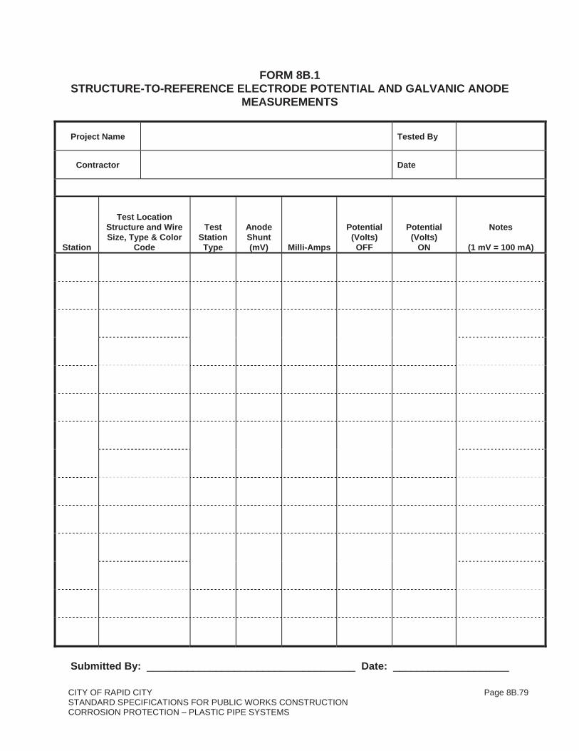
CITY OF RAPID CITY Page 8B.79STANDARD SPECIFICATIONS FOR PUBLIC WORKS CONSTRUCTION CORROSION PROTECTION – PLASTIC PIPE SYSTEMS
FORM 8B.1 STRUCTURE-TO-REFERENCE ELECTRODE POTENTIAL AND GALVANIC ANODE
MEASUREMENTS
Project Name Tested By
Contractor Date
Station
Test Location Structure and Wire Size, Type & Color
Code
Test Station Type
Anode Shunt(mV) Milli-Amps
Potential(Volts)OFF
Potential(Volts)
ON
Notes
(1 mV = 100 mA)
Submitted By: ____________________________________ Date: ____________________

CITY OF RAPID CITY Page 8B.80STANDARD SPECIFICATIONS FOR PUBLIC WORKS CONSTRUCTION CORROSION PROTECTION – PLASTIC PIPE SYSTEMS
FORM 8B.2
CITY OF RAPID CITYSHEET _______ OF ________
CORROSION PROTECTION - PLASTIC PIPE SYSTEMS DATE:___________________
TEST TAKEN BY:_____________
TRACER WIRE POTENTIAL AND ELECTRICAL CONTINUITY TEST WORKSHEET CLIENT:__________________________________ PROJECT#: ____________________________
PROJECT:________________________________ LOCATION:______________________________
PURPLE COLOR: _____NORTH OR _____WEST / TERMINAL LOCATION: ____TOP OR _____BOTTOM
GRAY COLOR: _____SOUTH OR _____EAST / TERMINAL LOCATION: ____TOP OR _____BOTTOM
FROM STATION ______+______ TO STATION ______+_______ TOTAL DISTANCE (FT) = ___________ PROVIDE A SKETCH BELOW (INCLUDE TEST CONNECTIONS, DISTANCES, STATIONING, ETC.):
START TEST POINT STA
END TEST POINT STA AT START, TOP TERMINAL COLOR ___________ POTENTIAL BEFORE TEST
NOTES
V
NOTES
V
NOTES
VAT START, TOP TERMINAL COLOR ___________ POTENTIAL AT TEST
V V VAT START, BOT TERMINAL COLOR ___________ POTENTIAL BEFORE TEST V V VAT START, BOT TERMINAL COLOR ___________ POTENTIAL AT TEST
V V VAT END, TOP TERMINAL COLOR ___________ POTENTIAL BEFORE TEST V V VAT END, TOP TERMINAL COLOR ___________ POTENTIAL AT TEST
V V VAT END, BOTTOM TERMINAL COLOR ___________ POTENTIAL BEFORE TEST V V VAT END, BOTTOM TERMINAL COLOR ___________ POTENTIAL AT TEST
V V V
RESULTS/NOTES:

CITY OF RAPID CITY Page 8B.81STANDARD SPECIFICATIONS FOR PUBLIC WORKS CONSTRUCTION CORROSION PROTECTION – PLASTIC PIPE SYSTEMS
FORM 8B.3 INDIVIDUAL WIRE JOINT BOND RESISTANCE TEST SUMMARY PIPE NAME/SIZE CONTRACTOR
DATE SHEET OF
Conduct test at DLRO min.10 A. current output 6,000 micro-ohm setting
CalibrationTime/By
MAXIMUM ALLOWABLE JOINT WIRE RESISTANCE
No. 2 AWG Joint Bond Wires Structure or Bond Type and Length Micro-Ohms
Two (2) Joint Bond Wires (18" Long)
Three (3) Joint Bond Wires (18" Long)
Test No.
PipeJoint No.
Approx. Pipe Stationing at
Joint Measured
Measured Bond
Resistance (Micro-Ohms)
Type of Joint & Pass Yes or No. If No Add Another
Additional Bond Micro-
OhmsTime
Measured Tested By
© RUSTNOT

CITY OF RAPID CITY Page 8B.82STANDARD SPECIFICATIONS FOR PUBLIC WORKS CONSTRUCTION CORROSION PROTECTION – PLASTIC PIPE SYSTEMS
ATTACHMENT A and B PVC PIPE and DUCILE IRON FITTINGS CERTIFICATION
CONTRACT: DATE:
CONTRACTOR:
PIPE MANUFACTURER:
DUCTILE IRON FITTINGS MANUFACTURER:
This certification applies to PVC pipe and Ductile Iron Fittings, as may be provided byManufacturers as identified above. Omission of any required project certification herein does notrelieve the Pipe or Ductile Iron Fittings Manufacturers or the CONTRACTOR fromresponsibilities of performance as may be required by the Contract Documents.
For pipe and pipe materials, joints and fittings to be supplied on the above referenced contract, the listed Pipe Manufacturer certifies as follows:
1. The PVC pipe shall be manufactured as specified in Section 8A – Water Piping Systems – of the Standard Specifications.
2. Ductile Iron Fitting Manufacturer shall provide required coatings and linings in accordance with Section 8B – Corrosion Protection - Plastic Pipe Systems – of the Standard Specifications.
[Remainder of page left blank intentionally]

CITY OF RAPID CITY Page 8B.83STANDARD SPECIFICATIONS FOR PUBLIC WORKS CONSTRUCTION CORROSION PROTECTION – PLASTIC PIPE SYSTEMS
ATTACHMENT APVC PIPE CERTIFICATION
IN CERTIFICATION THEREOF:
Name:
Title:
Signature:
Company:
Address:
Phone: e-mail:
This certification shall be sent by the Pipe Manufacturer to the CONTRACTOR, and then forwarded by CONTRACTOR to ENGINEER. This certification shall be signed by an authorized representative (with power of attorney) of the Pipe Manufacturer.
NOTARY:
The above certification was signed by of
in my presence on , 20 __
Notary Public:
My Commission Expires On: 20

CITY OF RAPID CITY Page 8B.84STANDARD SPECIFICATIONS FOR PUBLIC WORKS CONSTRUCTION CORROSION PROTECTION – PLASTIC PIPE SYSTEMS
ATTACHMENT BDUCTILE IRON FITTINGS CERTIFICATION
IN CERTIFICATION THEREOF:
Name:
Title:
Signature:
Company:
Address:
Phone: e-mail:
This certification shall be sent by the Ductile Iron Fittings Manufacturer to the CONTRACTOR, and then forwarded by CONTRACTOR to ENGINEER. This certification shall be signed by an authorized representative (with power of attorney) of the Ductile Iron Fittings Manufacturer.
NOTARY:
The above certification was signed by of
in my presence on , 20___
Notary Public:
My Commission Expires On: 20