SECTION 3.0 TECHNICAL SPECIFICATION 3.6 ADDRESSABLE...
21
Cawangan Kejuruteraan Mekanikal – Revision 2016 Section 3.6- Addressable Fire Alarm System © Copyright CKM 2016 1 SECTION 3.0 TECHNICAL SPECIFICATION 3.6 ADDRESSABLE FIRE ALARM SYSTEM
Transcript of SECTION 3.0 TECHNICAL SPECIFICATION 3.6 ADDRESSABLE...
Cawangan Kejuruteraan Mekanikal – Revision 2016
Section 3.6- Addressable Fire Alarm System © Copyright CKM 2016 1
SECTION 3.0 TECHNICAL SPECIFICATION
3.6 ADDRESSABLE FIRE ALARM SYSTEM
Cawangan Kejuruteraan Mekanikal – Revision 2016
Section 3.6- Addressable Fire Alarm System © Copyright CKM 2016 2
Table of Contents
1.1 GENERAL ................................................................................................................ 3 1.2 SYSTEM DESCRIPTION ........................................................................................ 4 1.3 ADDRESSABLE FIRE ALARM PANEL .................................................................. 4
1.3.1 Operator Workstation ................................... 6
1.3.2 Printer .............................................. 6
1.3.3 Power Supply ......................................... 7
1.3.4 Battery Supply ........................................ 7
1.3.5 Surge and Transient Protection for Fire Alarm Panel ............. 7
1.3.6 Sistem Pengawasan Kebakaran Automatik .................... 8 1.4 SYSTEM OPERATION AND CONTROLS .............................................................. 8 1.5 FIRE CONTROL SEQUENCES ............................................................................ 11 1.6 ADDRESSABLE AUDIBLE ALARMS AND ELECTRONIC SOUNDER ............... 12 1.7 FLASHING LIGHTS AND RELAYS ....................................................................... 12 1.8 AUTOMATIC DETECTION DEVICES .................................................................. 12
1.8.1 Addressable Heat Detectors ............................. 12
1.8.2 Addressable Smoke Detectors ............................ 12
1.8.3 Addressable Duct Detectors .............................. 13
1.8.4 Addressable Manual Call Points ........................... 13
1.8.5 Isolators ............................................ 13 1.9 INTERFACE AND MONITORING UNITS ............................................................. 14 1.10 ENVIRONMENTAL CONDITIONS ........................................................................ 14 1.11 SYSTEM OF WIRING ........................................................................................... 14
1.11.1 Above Ground ...................................... 15
1.11.2 Under Ground ...................................... 15
1.11.3 Wiring in Conduit/Trunking (Surface or Concealed) ........... 16
1.11.4 Metallic Conduits .................................... 16
1.11.5 Cable Trunking ..................................... 16
1.11.6 Cable Trays ........................................ 17
1.11.7 Cable Ladder ....................................... 18 1.12 SPECIFICATION FOR TRANSIENT BARRIER ................................................... 18
1.12.1 General ........................................... 18
1.12.2 Overall Transient Barrier Performance ..................... 19
1.12.3 Installation ......................................... 19
1.12.4 Specification for 10 Amps Power Line Filter (PLF) ............ 20 1.13 PAINTING .............................................................................................................. 21 1.14 SAMPLE OF MATERIAL FOR SUBMISSION AND APPROVAL ......................... 21
Cawangan Kejuruteraan Mekanikal – Revision 2016
Section 3.6- Addressable Fire Alarm System © Copyright CKM 2016 3
1.0 TECHNICAL SPECIFICATIONS FOR ADDRESSABLE FIRE
ALARM SYSTEM
1.1 GENERAL
The system shall be totally solid state, microprocessor based and shall include but not limited to the following:
i. Addressable Manual Call Points.
ii. Addressable Audible Alarms.
iii. Addressable Automatic Detection Device.
iv. Flashing Light and Relays.
v. Addressable Fire Alarm Panels.
vi. Wiring.
vii. Power Supply.
viii. Battery Supply.
ix. Interfacing Unit.
x. Painting.
xi. Mode of Operation.
xii. Lightning and Surge Protection.
All equipment and installation conforming to the following:
i. BS 5839-1:2002+A2:2008 (Fire Detection and Alarm System in Building);
ii. BS 5839-4:1988 (Fire detection and alarm systems for buildings. Specification for
control and indicating equipment);
iii. The requirements of Jabatan Bomba dan Penyelamat; and
iv. The latest IEE regulation on wiring and conduit work.
v. The control system shall be operated on 24 volt DC supply and in accordance to MS 1745: Part 4: 2004 or BS EN 54-4:1998.
vi. The control functions and indication on the Addressable Fire Alarm Panel shall
be in accordance to the MS 1745: Part 2: 2004 or BS EN 54-2:1997+A1:2006 and of type approved by Jabatan Bomba Dan Penyelamat Malaysia.
Locations of all addressable audible alarms, addressable automatic detectors, addressable manual call points, flashing lights and addressable Fire Alarm Panel are approximately shown in the Tender Drawings. The Contractor shall be required to furnish a complete layout of the controls for the addressable Fire Alarm Panel including mimic diagrams and wiring circuits for the control systems for the approval of the S.O. before fabrication of the units.
The wiring from the equipment terminal strips to make up for the complete installation of the Fire Detection and Alarm System shall be done by the Contractor. Smoke detectors
for air handling unit (duct) shall be supplied and installed by the Fire Fighting
Contractor.
Cawangan Kejuruteraan Mekanikal – Revision 2016
Section 3.6- Addressable Fire Alarm System © Copyright CKM 2016 4
All offers of detector, manual call point, addressable audible alarms and electronic
sounder shall be supported by copies of the current test certificates from SIRIM or recognised laboratory. All the electrical work shall use JKR approved product listed on J-MAL / Electrical Material Approval List.
1.2 SYSTEM DESCRIPTION
The system shall be the addressable and intelligent type using the latest microcomputer technology and is aimed to have a long life with compatible product upgrades and expansions to include other advanced building management system.
The system shall have the following features: i. Each sensor/detector is individual addressed and shall be given a label either as
an individual or in group using software application.
ii. The advanced fire sensors and sophisticated signal processing shall be used leading to the minimum possible rate of unwanted alarms.
iii. All wiring and position of all devices in the system shall be traceable from the
main control panel and a record of these can be obtained from the printer.
iv. Location of where the fire first started and the latest location of the fire shall be shown on the LCD display screen on the main control panel complete with audible alarms.
v. All other locations where the fire has spread to shall be scrolled on the LCD
display screen. All these locations and events shall be printed with exact date and time of the events.
vi. The sensor shall incorporate an incoming and outgoing isolator to minimise
isolation of the system in the event of short circuit and open circuit faults.
All the components of the system shall be supplied from only one manufacturer. A system using addressable fire alarm panel manufactured by manufacturer licensed by the detector manufacturer is also acceptable provided the detector manufacturer submit letter of undertaking with this tender, to provide all technical support and be responsible for all system compatibility and performance.
1.3 ADDRESSABLE FIRE ALARM PANEL
The supply and installation of the Addressable Fire Alarm Panel shall be completed with LCD display screen, printer, keyboard, mimic diagram, rechargeable batteries, charger and alarm bell, ELCB and surge arrestor.
The fire alarm shall be configured around advanced microcomputer based technology. The numbers of loops and devices are as indicated in the Schedule of Design Requirements and drawings.
Cawangan Kejuruteraan Mekanikal – Revision 2016
Section 3.6- Addressable Fire Alarm System © Copyright CKM 2016 5
The keyboard shall be used to configure, programmed and maintain the fire alarm system. The system shall provide storage capacity and recording of the events of incidents up to minimum 250 events and provide a hard copy showing description, time and date when requested to do so. It shall include the following equipments: i. A signal unit indicating “supply on” and “power failure”.
ii. Zone indicating “a fire”, “a fault” and “healthy circuit” conditions.
Each zone indicating unit shall be self-contained incorporating a temper-proof
key-operated rotary selector switch with provisions for testing circuit, fault,
alarm condition and also for circuit isolation.
iii. Zone fault buzzer, fault alarm muting switches, fire alarm buzzer, fire alarm muting switches and reset switches.
iv. Evacuate -start sounders button, stop sounder button, system reset and cancel fault buzzer buttons.
v. The Main Fire Alarm Panel shall be connected to the nearest Jabatan Bomba
Dan Penyelamat Malaysia using Sistem Pengawasan Kebakaran Automatik (SPKA) as per Schedule of Design Requirements. All associated fees for this service shall be deemed to be included in the tender price and paid by the contractor.
vi. Constant voltage battery trickle charger, change-over contactor and all
associated voltmeter, ammeter, control switches, HRC fuses and relays.
vii. Signal lamps to indicate battery and charger conditions.
viii. Space for storing a portable testing unit.
ix. All necessary labels (clear perspex reverse engraved and screws) HRC fuses, terminals block, relays, wiring etc.
x. Provision for remote monitoring inclusive of visual/audible indications of the
conditions of electrical supplies and status of all fire pumps and water level in storage tanks and air handling units. Electrodes shall be provided to indicate water level (high, low and normal) and also smoke detector for AHU room. The smoke detector for AHU Room when actuated shall only cut out supply to that particular zone and not the whole building.
xi. An approved perspex mimic panel (6mm thick) with zone illumination shall also
be provided to indicate the effected zone of the floor. The layout of the fire services for the whole of the building shall also be indicated on the mimic panel. The mimic diagram shall be first submitted to the S.O approval. The Fire Alarm Panel shall be constructed from 18 s.w.g. mild steel sheets, adequately braced. The compartments for the storage of batteries shall have adequate vents and corrosion resistant treatment. The panel shall be properly cleaned and phosphate sealed, followed by two coats of baked enamel of standard white colour or other if request by the S.O.

Cawangan Kejuruteraan Mekanikal – Revision 2016
Section 3.6- Addressable Fire Alarm System © Copyright CKM 2016 6
1.3.1 Operator Workstation
The Work Station shall be Intel i-7 or latest Microprocessor, Desktop computer with a
truly multi-tasking operating system performing multiple tasks simultaneously. Operator workstations shall be provided with multi-tasking operating system software
such as Window 10 or latest version of window c/w latest version of anti-virus software. Operating systems which provide only foreground / background operation, or are based on DOS, or concurrent DOS, are unacceptable. The workstations shall operate at a minimum system clock speed of 3.2 GHz, with at least 1 GB of RAM and 500GB of Hard Disk memory.
One (1) number of Operator workstation shall be provided at the Control Room.
The Operator workstations shall include as a minimum of a CD ROM of speed 52X or better. The Operator workstations shall include an optical mouse system in conjunction with the keyboard as the primary operator interface method. The keyboard shall also have at least 12 Function keys. Either mouse or keyboard shall be able to be utilized interchangeable for operator interface. The Operator Workstations Flat screen monitor shall be 24" in size with resolution of 1600 x 1200 and 32 bits colours to facilitate colour graphics presentation c/w built-in speakers. The Operator workstations shall simultaneously support all peripherals as specified. Peripherals shall be defined to include, serial printers, plotters, and auto answer/auto dial modems, streamer tape back-up systems, facsimile machine interface, colour inkjet printers, computer video image capture boards and colour or black and white digital scanners.
1.3.2 Printer
Supply a high speed 24 pin-printer or better that operates at 300 characters per second (CPS) normal speed. The printer shall accept continuous fan-fold or cut sheet paper from 1 to 4 part forms. For ease of ribbon replacement, the printer shall have a clean hands removable ribbon cartridge. The printer shall be supplied with a PC adapter, cable and stand to store the fan-fold paper supply. A special function key on the PC shall grant printing any CRT screen display. The contractor shall supply one (1) set of Alarm Printer and one (1) set of Report Printer
and shall be located in Control Room.
Alarms shall automatically print on occurrence with the PC on-line and functioning as a network workstation. If an alarm printer is off-line, alarm messages shall be automatically routed to the report printer in the same room. If an alarm message cannot be reported on any printer, the alarm message shall be buffered in the controller unit until one of the printers comes back on-line.
Cawangan Kejuruteraan Mekanikal – Revision 2016
Section 3.6- Addressable Fire Alarm System © Copyright CKM 2016 7
The report printer shall be used to provide a hardcopy of all critical alarms messages, trend log, summary, totalizing, logging, management reports and all other system reports mentioned in this specification. Specific messages such as switchover, hardware failure, communication errors and failure to execute commands shall also be routed to thus printer.
1.3.3 Power Supply
The control and indication equipment shall be adaptable for operation either on the mains electrical supply or storage battery exclusive for this system. The power supply equipment shall also include battery charger, rectifier, transformer, protective circuit fuses, ammeter, voltmeter and fault warning devices.
1.3.4 Battery Supply
The batteries shall be of the maintenance free sealed lead-acid battery rechargeable type. Its capacity shall not be less than as indicated in the Schedule of Design Requirements such that power is available to supply quiescent load resulting from the disconnection or failure of the mains electrical supply, for a minimum period of 72 hours. The battery supply shall be capable of supplying a maximum alarm load for a period of at least an hour. The contractor shall submit calculations on the battery loadings prior to the tender submission to ensure its capacity satisfies the conditions stated above. The battery charger shall be capable of bringing the batteries to full charge within 8 hours’ operation on mains supply. It shall incorporate dual charging rate, one for quick boosting and the other for trickle charge. Fault warning devices shall be included to indicate any charging failure or mains failure.
1.3.5 Surge and Transient Protection for Fire Alarm Panel
Surge and transient protection at Fire Alarm Panel must be provided for AC input for all panels - sub panels and signal line running externally. It should comply with the standard such as ANSI/IEEE C 62.41, AS 1768:1991 and BS 6651:1999.
The surge protection for power lines must comply with: ANSI/IEEE C62. 41 - 1991 Cat A and B, ANSI/IEEE C62. 45 - 1987 Life cycling test, AS/NZS 1768/1991 Cat A and B, BS 6651:1999 Cat A and B The surge protection for signal lines must comply to:
ANSI/IEEE C62. 41 - 1991 Category B

Cawangan Kejuruteraan Mekanikal – Revision 2016
Section 3.6- Addressable Fire Alarm System © Copyright CKM 2016 8
1.3.6 Sistem Pengawasan Kebakaran Automatik
The Sistem Pengawasan Kebakaran Automatik abbreviated to SPKA, is a designated building’s fire alarm warning signal being directly link to the Jabatan Bomba dan Penyelamat Malaysia emergency response system via an Internet-based communication system (SCADA) and mobile telecommunication line (SMS). The system shall comprise of fire service module which receive alarm signal from Fire Alarm Panel and alert the building owner thru Short Message Service (SMS) for verification before it is escalated to JBPM for action.
1.4 SYSTEM OPERATION AND CONTROLS
When a zone is activated, the alarm bell/sounders sound continuously and all other alarm bells/sounders shall have an intermittent ringing for at least 30 seconds before all the alarm bells/sounders starts ringing in the building concerned. All signals have to be relayed to the Main Alarm Panels.
i. Essential Controls
Essential controls are revealed on unlocking and opening the front cover of the control panel.
ii. Evacuate - Start Alarm Bells / Sounders On operation of this button all system alarm devices and system outputs are switched to evacuate mode, irrespective of any pre-programmed groupings.
iii. Stop Alarm Bells / Sounders On operation of this button all system alarm devices and system outputs are returned to the quiescent (quiet mode) state irrespective of their previous state. The master alarm buzzer within the control panels remains in operation in an intermittent state.
iv. System Reset On operation of this button the system will check the satisfactory operation of all system devices and return to the quiescent system state before an incident. If there is smoke or heat remaining in the immediate vicinity of a sensor or if a manual call point has not been reset the system will return to a fire condition. The system cannot be reset until the stop sounders button has been operated. Any faults or warnings before a fire condition will be reannunciated following a system reset.
v. Cancel Fault Buzzer This button silences the internal fault buzzer while the visual indication of a fault remains on the panel.
Cawangan Kejuruteraan Mekanikal – Revision 2016
Section 3.6- Addressable Fire Alarm System © Copyright CKM 2016 9
vi. Operation of Master Alarms The two master alarm circuit’s resident within the panel must be operated using the menu-driven special function keys.
vii. Setting the Clock The panel includes an internal clock that operates independently of any power supply. This self-adjusting clock can be changed by using the menu-driven special function keys.
viii. System Information System information can be obtained from the control panel and either displayed on the four line liquid crystal display and printed out by the integral printer.
ix. Display Test The lamps and internal buzzer must be tested individually.
x. Other System Controls Other system controls can be operated using the menu-driven special function keys. These controls can only be accessed by entering a user defined access code.
xi. Device Isolation The warning lights on the panel are illuminated when any device on the system is isolated. Devices, systems input or outputs and group of devices may be isolated manually or automatically. Automatic isolation can take place on selected days of the weeks and/or in up to eight pre-set times zones. In addition, the optical smoke detection channel can be de-sensitized within set time periods and/or specific days. No warning is given as the heat sensing element in the same head will continue to function normally. This action is however recorded in the event log.
xii. System Configuration and Labeling Changes must be made to the configuration of the system and to device or zone labels.
xiii. Operation of Sectors and Auxiliary Relays Individual sectors must have alert or evacuate modes and Auxiliary Relay circuit’s resident between the control panels must be activated.
xiv. Addressing and Labelling
a. Allocation of Addresses
All addresses are allocated automatically by the control panel when the circuit is powered up. These addresses take the form of a number and are allocated on a sequential basis. Once allocated they are referred to as the outstation number.
Cawangan Kejuruteraan Mekanikal – Revision 2016
Section 3.6- Addressable Fire Alarm System © Copyright CKM 2016 10
b. Configuration and Labels Storage and Recovery
If the number configuration and labels have not been previously entered the system will automatically default to sound all alarms in the evacuate mode in the event of a fire and will signal the location as the outstation number.
When a configuration and labels are entered they must be stored on a battery backed RAM card. Once stored they will be automatically recovered to the circuit when addresses are reallocated. Any system changes must therefore be stored on the RAM card.
c. System Labeling
Alphanumeric labels of up to 32 characters can be given to each of the outstation addresses. This label needs to be unique. Other system inputs and outputs that do not have their own outstation address (e.g. conventional manual call points and inputs/outputs from interface units) can be given their own label of up to 28 characters. If zoning is used each zone can be given a label of up to 32 alpha-numeric characters.
d. System Zoning
Any system trigger device or input can be grouped into a zone. Each zone can be given a label of up to 32 characters. If there is a fire incident within a zone, the zone label will appear on the liquid crystal display. However, incidents at individual devices within the zone will be recorded separately on the event log.
e. System Sectoring
In this system both alarm devices and trigger devices are grouped together into sectors. If a fire incident occurs within a sector, the alarm devices in that sector will operate. The alarm devices within other sectors can than be linked to the original group so that they will sound alert or evacuate in response.
Using this system a comprehensive two stage alarm pattern can be built up throughout the site.
Sectors can be isolated in the same way as zones or devices and can also be assigned a delay period of up to ten minutes giving an opportunity to investigate and incident before evacuation takes place.
f. Alert and Evacuate Signaling
The alert signal and evacuate signal can be configured by the user to operate continuously, intermittently at interval of half a second, one second or two seconds or giving a hi/low tone at the same time intervals. The systems electronic sounders shall be operated by pulses from the control panel and are therefore all synchronized.
Cawangan Kejuruteraan Mekanikal – Revision 2016
Section 3.6- Addressable Fire Alarm System © Copyright CKM 2016 11
g. Fire Data
A memory of up to 100 of the previous fires data shall be provided including the time and date of occurrence, outstation number and type of event.
h. Faults and Warnings
Any current outstanding faults or warnings of device isolation must be displayed and alarm sounded.
i. Events Data
A memory of up to minimum 250 of the previous system events including fires, faults and operational changes must be provided including the time and date of occurrence, outstation number (where relevant) and type of event.
j. Loop Map
A diagram showing each outstation number, the number of all outstations connected directly to it and whether it is positioned on the main loop, a sub loop or spur, must be provided.
k. Status
The operational status of any device or group of devices must be continuously monitored and any faults occurring must be recorded by the printer c/w alarm. This alarm must not be cancelled until the faults are rectified.
1.5 FIRE CONTROL SEQUENCES
Upon activation of a fire alarm device:
6.1 All AHUs of the affected FLOOR and ventilation system shall be switched off. The AHUs on the remaining floors shall remain operational.
6.2 Smoke-spill fans and pressurized fans shall be operated through the fire alarm
system. Fans can only be stopped manually from central panel.
6.3 Activate the fire alarm signaling devices as specified. 6.4 Signal to lift control panel indicating fire.

Cawangan Kejuruteraan Mekanikal – Revision 2016
Section 3.6- Addressable Fire Alarm System © Copyright CKM 2016 12
1.6 ADDRESSABLE AUDIBLE ALARMS AND ELECTRONIC SOUNDER
The bell shall have an operational requirement complying with MS 1745: Part 3: 2004 or BS EN 54-3:2001. The bell shall be minimum 150 mm (6”) in diameter with pressed steel gong finished in red. The bell shall be the solenoid operated type rated at 24V DC. The sound level produced shall be at least as indicated in the Schedule of Design Requirements. The electronic sounder shall be of 24 V DC type. It shall have a remote switching facility to enable sound to be changed by an exterior switch from intermittent or warble to continuous to signal change in state of alarm condition e.g. from Alert to Evacuate. It shall also have a volume control to enable sound level to be altered to suit application within a range of 65 dB (A) to 100 dB (A).
1.7 FLASHING LIGHTS AND RELAYS
Flashing relays shall be of a type suitable for 24V DC operation and capable of providing flashing lights at not less than 50 signaling point each. The rate of flashing shall be even and not less than 110 ± 30 flashes per minute with an on/off time ratio of between 4: 1 and 2: 1. Each flashing light shall have a red cap of not less than 50 mm in diameter The lamps shall continue to flash even if the call point is reset. If the call point is reset at the moment of acknowledgement, lamps will go out; otherwise the lamps will show a steady light.
1.8 AUTOMATIC DETECTION DEVICES
1.8.1 Addressable Heat Detectors
The heat detector shall be the Thermistor Rate Of Rise and fixed temperature type and shall comply with BS EN 54-5:2001. The detectors shall have a response time of 15 sec with a temperature rise of 30 °C per minute as per BS EN 54-5:2001. Detectors shall automatically reset upon cooling.
All heat detectors shall be completed with base plate suitable for ceiling mounting. They shall be installed in such a way that each may be readily withdrawn from service for testing or replacement without impairing the effectiveness of the remaining detectors and installation.
1.8.2 Addressable Smoke Detectors
The smoke detectors shall comply with BS EN 54-7:2001 and the type shall be as per Schedule of Design Requirements.
The smoke detector shall be complete with base plate of decorative ring suitable for ceiling mounting. The smoke sensor shall be able to detect a full spectrum of fires as defined in BS EN 54-7:2001.

Cawangan Kejuruteraan Mekanikal – Revision 2016
Section 3.6- Addressable Fire Alarm System © Copyright CKM 2016 13
1.8.3 Addressable Duct Detectors When duct sensors are required to be installed in air-conditioning ducting system, the smoke sensor shall be of a type suitable for the intended application and shall comply with BS EN 54-7:2001 When smoke is present, a signal from the detector deactivates the fans in the system in which the detector is installed. However, smoke control system commands must override fan deactivation by a duct smoke detector. In NFPA 90A (NFPA 2002, Standard for the Installation of Air Conditioning and Ventilating Systems), section 6.4.2.1 provides the requirements for duct smoke detectors. Supply duct smoke detectors must be located downstream of the system filters and ahead of any branch connection. In mixing systems, this is usually after the return air connection.
1.8.4 Addressable Manual Call Points
Manually operated call points shall comply with BS EN 54-11:2001. Breaking the frangible element shall cause the call point to change to and remain in; its alarm initiating state and no further manual action shall be required. The call point casing shall be shatter proof, corrosion resistant and finished in signal red.
It shall operate on a direct mechanical linkage principle to prevent sticking problem associated with limit switch type call points. It shall have LED and a transparent Perspex cover to prevent vandalism.
The manual call points shall be of the break glass type with corrosion resistant metal casing suitable for surface fixing. Each manual call point shall have the words "API - PECAH KACA" inscribed on it. All manual call points shall have alternative provisions to enable open or closed circuit systems. Manual call point shall be mounted at a height of 1.4 metres from the floor, easily accessible, well illuminated and conspicuous positions free from obstruction.
Manual call point maybe flushed mounted where they can be seen readily. In locations where they may be viewed from the side (eg. In corridor) they should be surface mounted or semi-recessed in order to present a side profile area of not less than 750 mm2.
1.8.5 Isolators Sensors and devices shall have built-in isolators or fault-isolation module shall be provided to enable part of a fault-tolerant loop to continue operating when a break occurs on the loop. The isolator shall have a LED that blinks to indicate normal status and ON to indicate a break on the loop.
Cawangan Kejuruteraan Mekanikal – Revision 2016
Section 3.6- Addressable Fire Alarm System © Copyright CKM 2016 14
1.9 INTERFACE AND MONITORING UNITS
The interface unit shall be a self contained wall mounted unit with its own power supply that can control up to four sectors of bells, visual alarm signals. The unit shall be capable of linking the addressable system to existing conventional fire alarm system, total flooding fire extinguishing system, alarm bell, hose reel system, air conditioning units, sprinkler floor control valve, etc.
1.10 ENVIRONMENTAL CONDITIONS
The alarm system shall be capable of withstanding local environmental conditions and complying with current regulations.
1.11 SYSTEM OF WIRING
All circuits shall be designed such that the controllers will perform their functions in an
ambient temperature up to 50C. The system of wiring shall be surface wiring, concealed wiring, surface conduit wiring or concealed conduit wiring as indicated in the Drawings and/or Schedule of Design Requirements. The wiring systems shall comply with MS IEC 60364-5-52. All wiring shall be run neatly and in an orderly manner. They shall be routed parallel to building wall and column lines in a coordinated manner with other services. The wiring throughout shall be on the ‘looping-in system’ and no ‘tee’ or other types of joints are allowed. No reductions of the strands forming the conductors are allowed at all terminals. All strands shall be effectively secured by approved means. Wiring which are not embedded in concrete or concealed behind plaster shall be run in an accessible manner on the beams, underside of slabs or below pipes, ducts, and down drops shall be run on the surface of columns or walls. Concealed wiring shall be installed in such a way that plaster can be applied over their thickness without being subjected to spalling or cracking. Cables serving different operating voltages and functions shall be segregated. All cables shall be legibly marked on the external surface with at least the following elements; Manufacturer’s identification, Voltage designation, Nominal area of conductor and Standard Numbers. Standard colour coded cable shall be used for three phase circuit to identify the phase conductors, neutral conductor and protective conductor respectively. Opening on floor, wall or partition through which cable, trunking, conduit or other wiring passes through shall be sealed according to the appropriate degree of fire resistance after the installation. Chipping and cutting of concrete are not allowed unless otherwise approved by the S.O.’s Representative. The Contractor is required to work in conjunction with the building contractor for the provision of openings, trenches, core-holes, chases etc. as the building concreting work progresses.

Cawangan Kejuruteraan Mekanikal – Revision 2016
Section 3.6- Addressable Fire Alarm System © Copyright CKM 2016 15
In steel frame structures, the wiring system shall be rigidly and securely supported and fastened in place onto the structural steel beams, purlins and columns by fasteners such as clamps, clips, anchors, straps, hangers, supports or similar fittings. The fasteners shall be designed and installed as not to damage either to steel structures or wiring system. The fasteners shall be installed at intervals not exceeding 1000 mm, and within 300 mm of every outlet box, junction box, device box, cabinet or fitting. Fasteners shall be of spring steel and/or galvanised steel, and where wires, rods or threaded rods are used with fasteners, they shall be of rolled carbon steel. The fasteners shall be finished with zinc coatings to resist rusting. Samples for the fasteners used shall be submitted to S.O.’s Representative for approval before they are used. Unless otherwise approved by S.O.’s Representative, no welding on and/or drilling holes into any members or components of the steel frame structures for the installation of fasteners are allowed.
1.11.1 Above Ground
The wiring above ground shall be wired and run in metallic conduit complying with BS 6004:2000. The type of wiring shall be twisted pair screen cable. The size of cable shall as specified in the Schedule of Design Requirements. All wiring shall be installed to comply with the latest edition of I.E.E. and Electricity Supply Act 1990 and Electricity Regulations 1994 / Suruhanjaya Tenaga regulations. All conduits are to be concealed or hidden from view.
All steel conduits supplied shall be heavy duty type.
1.11.2 Under Ground
Underground cable shall be carried in PVC/SWA/PVC. The Armoured Cable shall be manufactured and tested in accordance with MS 274 or BS 6346 and shall have high conductivity plain copper stranded conductors insulated with PVC suitable for a voltage of 600/1000V laid together and bedded with PVC, armoured with galvanised steel wires and sheathed with PVC. The size and type of the cable shall as specified in the Tender Drawing and Schedule of Design Requirements. All underground cable shall be armoured cable and shall be individually link back to the (main) fire alarm panel.
Cable marker shall be provided for all the underground cable with suitable distance.
The underground cable shall be laid on a 50 mm (2") thick compact sand bed and at least 900 mm below ground level c/w a layer of hard baked brick along its routes.
Cable connections shall be made to a socket integral with the back-plate.
Cawangan Kejuruteraan Mekanikal – Revision 2016
Section 3.6- Addressable Fire Alarm System © Copyright CKM 2016 16
1.11.3 Wiring in Conduit/Trunking (Surface or Concealed)
The cables used in conduit wiring, unless otherwise specified shall be similar to that described above. Unless otherwise specified in the Drawings and/or Schedule of Design Requirements, the conduits shall be of galvanised steel and conduit fittings shall be of galvanised steel or alloy materials. Cables above false ceiling shall be run in conduit or trunking.
The conduit or trunking shall generally be run on the underside of the floor slabs by mild steel brackets or suspenders. The conduit or trunking shall be suspended from the floor slabs or mounted against the wall by mild steel brackets. The mild steel brackets shall be anti-rust treated, painted with a primer and finished in orange enamel. The suspension structure shall be robust in constructions and adequately installed such that the conduit/trunking will not sag.
Flexible conduit shall be used for termination to equipment, which is subjected to movement or vibration. However, the length of this flexible conduit shall not exceed 400mm unless approved by the S.O.’s representative.
1.11.4 Metallic Conduits
Steel conduits shall be of galvanised, heavy gauge, screwed type complying with MS 275-1, MS 1534:PT.1, MS 1534:PT.2:Sec1, IEC 60423, IEC 61386-1 and IEC 61386-21. All steel conduit fittings shall comply with MS 275-2, MS 1534:PT.1, MS 1534:PT.2:Sec1, IEC 61035-1, IEC61035-2-1, IEC 61386-1 and IEC 61386-21. The steel conduits shall be fitted with brass bushes at the free ends and expansion devices at appropriate intervals. The ends of each length of steel conduit shall be properly reamed. The termination to the distribution boards, consumer units, switchgears and outlet boxes shall be effected by brass type smooth-bore bushes. All steel conduits shall be effectively earthed.
For laying underground steel conduit shall be used and buried at a minimum depth of 450 mm below ground level or 100 mm below floor slab or hard standing. Junction boxes, outlet boxes etc. shall be of galvanised sheet steel or alloy material or malleable cast iron. The covers shall be galvanised sheet steel or alloy material with thickness not less than 1.2 mm. Accessories such as junction boxes down dropping to luminaries shall have die-cast cone-shaped metal cover.
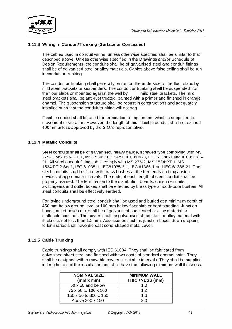
1.11.5 Cable Trunking
Cable trunkings shall comply with IEC 61084. They shall be fabricated from galvanised sheet steel and finished with two coats of standard enamel paint. They shall be equipped with removable covers at suitable intervals. They shall be supplied in lengths to suit the installation and shall have the following minimum wall thickness: -
NOMINAL SIZE
(mm x mm)
MINIMUM WALL
THICKNESS (mm)
50 x 50 and below 1.0
75 x 50 to 100 x 100 1.2
150 x 50 to 300 x 150 1.6
Above 300 x 150 2.0
Cawangan Kejuruteraan Mekanikal – Revision 2016
Section 3.6- Addressable Fire Alarm System © Copyright CKM 2016 17
All trunking elbows, offset and combination elbows, adaptors and tees shall be of same thickness as the straight trunking and shall be the type manufactured and supplied by the same trunking manufacturer.
The trunking shall be supported by fixing brackets so that the trunking will not be in contact with the walls or floor slabs. The brackets shall be installed at intervals not greater than 1500 mm for vertical runs and not greater than 1000 mm for horizontal runs. The brackets shall be derusted, finished in a primer and coated with standard enamel paint.
Wherever the trunking passes through a floor or a fire resistant wall, fire-resisting barrier shall be provided. At these positions the cables shall be sealed with non-hygroscopic fire resisting material of minimum 2-hour fire rating. In addition, the floor openings and wall openings shall be sealed with similar type of compound.
Cables running in the trunking shall carry conductor identification colours and shall be supported by split hard wood racks securely fixed at the base of the trunking and spaced not more than 600 mm apart. Cables for each final circuit shall be properly bunched together and labelled. Where conduit is tapped off from the trunking, suitable brass type smoothbore bushes shall be fitted at all conduit termination. Unless otherwise specified, all trunkings shall have either tinned copper tape of dimension not less than 25 mm x 3 mm as circuit protective conductor or earth cable of appropriate size. In the latter case, all trunking joints shall be bridged by means of tinned copper tape of dimension not less than 25 mm x 3 mm.
1.11.6 Cable Trays
Cable trays system shall comply with MS IEC 61537 and shall be fabricated from perforated galvanised sheet steel complete with all necessary bends, tee pieces, adaptors and other accessories. The minimum thickness of the sheet steel shall be 1.5 mm for cable trays with widths up to and including 300 mm and 2.0 mm for cable trays with width exceeding 300 mm. However minimum thickness for the sheet steel of the perforated hot dipped galvanised cable trays shall be 2.0 mm. Cable trays may either be suspended from floor slabs by hangers or mounted on walls or vertical structure by brackets at 600 mm intervals.
However where the above methods of installation are not feasible or practical, suitable floor mounted mild steel structures shall be provided. All supports, hangers and structures shall be robust in construction and adequately installed to cater for the weights of the cables and trays supported on them so that cable trays and cables will not sag. All supports, hangers, bracket and structures shall be anti-rusted, finished in primer and coated with standard enamel paint.
All supports, hangers, bracket and structure for the perforated hot dipped galvanised cable trays shall also be of hot dipped galvanised type. Fixing clips and cleats for cables on trays shall be installed by means of bolts, washers and nuts.
All tees, intersection units, adaptor units etc. shall be the type manufactured by the cable tray manufacturer unless otherwise approved by the S.O.'s Representative. Wherever cable tray pass through a floor or a fire resistant wall, fire-resisting barrier as mentioned above shall be provided.
Cawangan Kejuruteraan Mekanikal – Revision 2016
Section 3.6- Addressable Fire Alarm System © Copyright CKM 2016 18
1.11.7 Cable Ladder
Cable ladder system shall comply with MS IEC 61537 and fabricated from mild steel and finished in hot-dipped galvanised or epoxy powder coat complete with all necessary horizontal elbow, horizontal tee, horizontal cross, reducer straight, outside riser, inside riser, reducer left, reducer right, cable clamp, cantilever arm, hold down clip/clamp, hanger bar, vertical splice plate and horizontal splice plate for welded type and screwed type. The minimum thickness of the sheet steel shall be 2.0 mm.
Cable ladder may either be suspended from floor slabs by hangers or mounted on walls or vertical structure by cantilever arm. Cable ladder shall be supported rigidly and adequately by external spring hangers mounted on channel base. The cable ladder shall be supported at maximum intervals of 3000mm for in contact with the wall or floor slab surfaces. The spring hangers shall be supplied by the cable ladder manufacturer. All supports, hangers, and structures shall be robust in construction and adequately installed to cater for the weights of the cables and ladder supported on them so that cable ladder and cables will not sag. Rungs shall be spaced at 300mm nominal centres, welded to the rail sections by approved welding procedures. All rungs shall be perforated in accordance to the manufacturer’s design.
The cable ladders shall be supplied fully assembled with preparations for connections to straight sections or accessories using splice plates mechanically bolted together. Allowance shall be provided for longitudinal adjustments and expansion. The cable ladders when completed shall be smooth, free from all sharp edges and shall be capable of discharging any water that may be retained due to normal weathering.
All accessories shah be the type manufactured by the cable ladder manufacturer unless otherwise approved by the S.O.’s representative. Wherever cable ladder pass through a floor or a fire resistant wall, fire-resisting barrier as mentioned above shall be provided.
1.12 SPECIFICATION FOR TRANSIENT BARRIER
1.12.1 General
Transient Barriers shall be installed to provide lightning and transient protection for balanced and unbalanced data lines, signal and communications circuit used in instrumentation process control, communications and commuting applications.
They shall be series, in-line devices. Shunt or parallel devices are not acceptable. To ensure the maximum application flexibility and ease of testing. The Transient Barrier shall comprise primary and secondary protection. The Barriers shall be particularly designed to divert transients on long-lines, high exposure lines and lines susceptible to power line induction. Thus, the overall transient barrier (cap and base together) shall be a three stage protection device. The Transient Barrier shall be designed for temperature and tropical field conditions over operating temperature range 10 deg C to 50 deg C and relative humidity up to 95%. The primary surge diverter protection shall be high speed three element gas arrestor rated at 20kA 8/20 microsecond waveform.
Cawangan Kejuruteraan Mekanikal – Revision 2016
Section 3.6- Addressable Fire Alarm System © Copyright CKM 2016 19
The enclosure shall be lightweight ABS plastic. Cable termination shall be able to accommodate wire sizes up to 2.5 mm diameter. The secondary diverter shall comprise at least two different types of high speed secondary protection components, arranged as two stages of clamping separated by discrete line impedance overcurrent protection. The overcurrent protection shall be the self resetting solid state thermal switch type with one device in each wire circuit. The secondary protection clamping voltage shall be chosen to be between 1.10 times and 1.4 times the peak operating voltage of the circuit. The secondary protection shall have a minimum transient current rating of 5 kA on 8/20 microsecond wave shape on each protected wire.
1.12.2 Overall Transient Barrier Performance
The Barrier shall be designed to withstand both common mode and differential (transverse) mode transients. The overall Barrier shall have three stages of clamping. The Transient withstand conditions shall exceed ANSI/IEEEC 662.41 category B. The let through voltage response when measured at the equipment terminals of the barrier shall be stated when 6kV 1/30 microsecond pulse plus 3kA 8/20 microsecond pulse is applied to the line terminals. The Barrier shall protect the equipment against transients of at least this magnitude and wave shape and the Barrier itself shall not sacrificially fall or be damaged. The maximum let through voltage when tested shall not exceed 17V for circuit operating voltages under 6.3V, PROVIDED THAT if these levels of let through voltages are too high for the equipment being protected and cause damaged component through voltage shall be lower so that these problems do not occur. The barrier shall have a response time no greater than one microsecond.
The barrier shall have a 3dB attention frequency not less than one megahertz. The barrier shall be able to withstand and adequate/divert many transients over a long period. They shall not be one shot of self sacrificing devices.
1.12.3 Installation
The transient barriers shall be effectively earthed using high quality mechanical connections. They shall be earthed to the earth of the equipment that they are protecting and to no other earth.
Earth wires to leads shall be of 1.5 mm minimum diameter. They shall be laid alongside incoming cable pairs and kept remote from equipment side cables.

Cawangan Kejuruteraan Mekanikal – Revision 2016
Section 3.6- Addressable Fire Alarm System © Copyright CKM 2016 20
Since a transient barrier with primary and secondary protection is necessarily a non-symmetrical device, great care shall be taken in installation to ensure line-side and equipment connections are correct and not reversed. Earth leads shall be as short and direct as possible to minimize earth wire inductance.
1.12.4 Specification for 10 Amps Power Line Filter (PLF)
The PLF shall be rated for 220-240 VAC, 50Hz, single phase, 10 Amps continuous at 45 degrees C ambient, 0-95 % humidity. The series earth impedance measured at 50 Hz shall be less than 0.1 ohms. The PLF shall be suitable for both free standing operation and wall mounting The Peak Impulse Current (single shot) shall be greater than 12000 Amps when pulsed with an input condition, the energy absorption (single shot) shall exceed 300 Joules. The PLF shall be subjected to strict type testing using ANSI/IEEE 062 41-1980 input specifications. The testing shall include both of 6 kV 100 kHz, 500 Amps Cat A ringwave, and 6 kV 1.5/5.0 uSec +3kA 8/20u Sec dual mode category B pulses. With each type of pulse, particular care shall be exercised to test the PLF in both Common mode and Differential mode. The Common mode test shall involve measuring the response of the filter when the impulse is applied to both Active and neutral wires. The Differential mode test shall involve measuring the response of the filter when the pulse is applied to either of the Active or Neutral wire individually. Any capacitors between either line and earth shall be Y type. The category A and B test pulses shall be superimposed onto the normal 220-240 VAC Mains supply so that the pulse positions with respect to the 50Hz Mains supply can be varied throughout the cycle. Test results will not be accepted if they are superimposed on the 50 Hz supply. The PLF shall have an output clamping voltage of less than 490 V when the 6kV 100 kHz category A pulse is superimposed at the positive peak of a 50Hz 240 VAC Mains sinewave. This clause shall apply to both of Common mode and Differential mode tests. The PLF shall have an output clamping voltage of less than 600 V when the 6kV 1.5/5 uSec +3 kA 8/20uSec category B pulse is superimposed at the positive peak of a 50Hz 240 VAC Mains sinewave. This clause shall apply to both of Common mode and Differential mode tests. The PLF shall be specifically designed for filtering of low frequency disturbances. The 2dB attenuation frequency shall not exceed 2 kHz and shall preferably be below 2 kHz. The attenuation at 40 kHz shall be at least 40 dB. The PLF shall be specifically designed for lightning and surge protection powerlines. Classical Radio Frequency filters, even if combined with clamping devices, are not suitable.
Cawangan Kejuruteraan Mekanikal – Revision 2016
Section 3.6- Addressable Fire Alarm System © Copyright CKM 2016 21
1.13 PAINTING
All items to be painted shall be first cleaned and prime coated. The final colour shall be applied in two coats. The paint shall be red colour and gloss-finish type.
1.14 SAMPLE OF MATERIAL FOR SUBMISSION AND APPROVAL
The Contractor shall prepare Sample board of typical material proposed to use in the work and/or samples of workmanship (mock up) to the approval of the S.O, prior to commencement of the installation work. The sample board and/or samples of workmanship (mock up) shall comprise of but not limited to the conduits, conduit fittings, underground and above ground cables, addressable smoke and addressable heat detectors, hanger and support system, addressable alarm bells, break glass and etc. The cost of the sample board or samples of workmanship (mock up) is deemed to be included in the Contract.
---------------------------------------------- END OF SECTION 3.6 -------------------------------------------