Inspection & Test Plan for Pipiing Fabrication & Installation

33
Section 3 Fabrication & installation
1. General
We can process ALPOLIC and ALPOLIC/fr panels with regular machines and tools for aluminum and
wood. We can cut the panels with a circular saw, fold them after grooving with a router, and bend
them with a 3-roll bender. In order to join aluminum extrusions to ALPOLIC panels, we can choose a
suitable joining method from several alternatives. For installation, various types of fixing methods
suitable for Aluminum Composite Material (ACM) have been put forward and improved on for years.
We will look over basics of the processing methods and installation methods in this section.
ALPOLIC and ALPOLIC/fr are often simply referred to as “ALPOLIC” or “ALPOLIC panels” in this
section, because the fabrication and installation methods applicable to ALPOLIC mostly hold true to
ALPOLIC/fr as well. Regarding the product dimension and tolerance required for planning (design)
work of fabrication and installation, refer to “11: Panel dimension and tolerance” at the end of this
section.
2. Handling
ALPOLIC is a rigid panel, but a physical impact may
cause an edge deformation. Inclusion of hard particles
such as grains of sand and cutting chips caught
between ALPOLIC panels may cause visible
dent-damages in one or more adjacent panels. Take
note of the following precautions while handling ALPOLIC during fabrication and installation.
(1) Unpacking and repacking
a. Do unpacking and repacking works in a clean place.
b. Remove dusts and chips from ALPOLIC and the packing paper. Any hard particles between panels
will cause a dent-damage on ALPOLIC panels.
c. Handle ALPOLIC on a worktable. Do not handle it on the floor.
d. ALPOLIC should always be handled by two people with external face upward to avoid possible
rubbing of the ALPOLIC surface during handling.
(2) Transport
a. For transport, lay the packed ALPOLIC horizontally and do not place heavy goods on it.
b. Mark “Handle with Care”, “Keep Dry”, “No Hooks” and “This Side Up” clearly on the packing.
Dent
Hard particle
ALPOLIC
Fig. 3-1 Dent caused by inclusion of particle

34
(3) Fabrication
a. Prior to fabrication, clean off the worktable, temporary stand and both sides of ALPOLIC.
b. Ensure that cutting chips generated from saws, routers and drills are completely removed from the
interface between ALPOLIC and tools.
(4) Storage
a. Store ALPOLIC panels indoors with a flat rack system or a vertical rack system shown below.
b. In a flat rack system, pile the same size of panels on a rigid palette. Do not pile up different sizes
together. Our wooden crates can usually be stacked up to four crates high.
c. In a vertical rack system, lean panels closely against an inclined backing material within 10°. The
total thickness of leaning panels should not exceed 100 mm thick. Use veneer for backing cover and
place rubber mat on the bottom. Avoid scratches when pulling out from the rack and restoring it.
(5) Protective film
The protective film of ALPOLIC, consisting of two polyethylene layers of white and black, withstands
outdoor exposure for approx. 6 months. However, store the panels in dry and indoor atmosphere, to
minimize the natural-degradation of the protective film by moisture and direct sunlight during storage.
(6) PVC tape
Do not use adhesive tapes made of PVC (polyvinyl chloride) on the surface of protective film at any
time during storage, fabrication or installation. The plasticizer (an additive) in PVC tape will permeate
the film and attack the Lumiflon coating, which causes a gloss change problem on the coating. Any
types of PVC tapes may cause this problem, including duct tape, packing tape and insulation tape.
3. Processing method
(1) Summary
We can use wide variety of machines and tools to process ALPOLIC panels. We can classify these
machines and tools into conventional ones and automated ones. Generally, automated machines enable
high efficiency in large quantity analogous work. On the other hand, conventional machines and tools
are versatile and flexible. The former requires a costly investment for the machine, and the latter
requires skill for good work. The main machines and tools are as shown in the following table.
Flat rack Vertical rack
Within 10°
<100 mm No good
Rubber mat
Timber frame
Good
Fig. 3-2 Proper storing method

35
Table 3-1 Summary of machines and tools
Conventional tools and machines Automated machines
Processing Tools or machines No. Processing Tools or machines No.
Cut Table saw 1 Cut Panel saw 13
Hand circular saw 2 Square shear 14
Hand router 3 CNC router 15
Hand jigsaw 4 Groove Panel saw 13
Groove Grooving machine 5 CNC router 15
Hand router 3 Perforate Turret Puncher 16
Chamfer Hand trimmer 6
Plane 7
Make hole Hand drill 8
Punch Punching machine 9
Notch Notching tool 10
Bend Press brake 11
3-roll bender 12
1. Table saw 2. Hand circular saw 3. Hand router 4. Hand jigsaw
5. Grooving machine 6. Hand trimmer 7. Plane 8. Hand drill
9. Punching machine 10. Notching tool 11. Press brake 12. 3-roll bender
13. Panel saw 14. Square shear 15. CNC router 16. Turret puncher
36
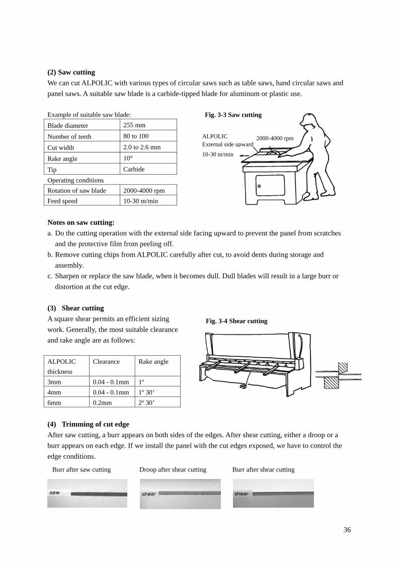
(2) Saw cutting
We can cut ALPOLIC with various types of circular saws such as table saws, hand circular saws and
panel saws. A suitable saw blade is a carbide-tipped blade for aluminum or plastic use.
Example of suitable saw blade:
Blade diameter 255 mm
Number of teeth 80 to 100
Cut width 2.0 to 2.6 mm
Rake angle 10°
Tip Carbide
Operating conditions
Rotation of saw blade 2000-4000 rpm
Feed speed 10-30 m/min
Notes on saw cutting:
a. Do the cutting operation with the external side facing upward to prevent the panel from scratches
and the protective film from peeling off.
b. Remove cutting chips from ALPOLIC carefully after cut, to avoid dents during storage and
assembly.
c. Sharpen or replace the saw blade, when it becomes dull. Dull blades will result in a large burr or
distortion at the cut edge.
(3) Shear cutting
A square shear permits an efficient sizing
work. Generally, the most suitable clearance
and rake angle are as follows:
ALPOLIC
thickness
Clearance Rake angle
3mm 0.04 - 0.1mm 1º
4mm 0.04 - 0.1mm 1º 30’
6mm 0.2mm 2º 30’
(4) Trimming of cut edge
After saw cutting, a burr appears on both sides of the edges. After shear cutting, either a droop or a
burr appears on each edge. If we install the panel with the cut edges exposed, we have to control the
edge conditions.
ALPOLIC External side upward
10-30 m/min
2000-4000 rpm
Fig. 3-4 Shear cutting
Burr after saw cutting Droop after shear cutting Burr after shear cutting
Fig. 3-3 Saw cutting

37
Namely, in saw cutting we should keep the saw blade
sharp enough to have a proper edge. In shear cutting,
we should adjust the clearance of the die properly. If
we need further trimming of the cut edge, we have to
trim the edge with a trimmer, plane or sandpaper.
In Solid, Metallic, Sparkling Colors, deep trimming
like chamfering may have an aesthetic effect. Use a
trimmer with a ball bearing chamfering bit or a plane
for woodwork. In working with plane, a guide ruler
will help to ensure a uniform edge.
In Stone and Timber, generally, deep trimming is not
suitable, because deep trimming harms the appearance
of Stone and Timber. If it is possible that passers-by
may hurt their fingers on the cut edges in Stone and
Timber, make the edges dull with fine sandpaper.
Normally, droop edges by shear cutting are mild
enough to ensure the safety of cut edges.
(5) Curving cut
Hand routers and trimmers can cut ALPOLIC in
curving lines. A guide template will help you to
stabilize this work. Jigsaws are also useful for cutting
complex shapes.
Notes on guide template:
a. Put the guide template on the external side of ALPOLIC,
to do the routing work through the guide template.
b. Remove the particles caught between the template and
ALPOLIC surface, to prevent dents and scratches.
(6) U-grooving
We can fold ALPOLIC after U-grooving in the backside.
Two types of machines are available for U-grooving. One is
a circular cutter type and the other is a router type. The
former includes hand grooving machines and panel saws,
and the latter includes hand routers and CNC routers.
Hand router Hand jigsaw
Fig. 3-7 Curving cut
Fig. 3-5 Hand trimmer and chamfering bit
Table ALPOLIC
Chamfer angle
Plane
Fig. 3-6 Chamfering with plane
Handy router
Guide plate
ALPOLIC
Worktable
Guide template for curving cut

38
U-groove shape
The diagram (in Fig. 3-8) shows a typical U-groove shape suitable
for folding ALPOLIC panels. It is important to leave 0.2-0.4 mm
of core. We recommend 90-110° grooves for 90° bending.
Hand grooving machine
Hand grooving machines can groove ALPOLIC. Use a cutter blade
having the proper groove shape as shown in Fig. 3-8. An example
of suitable cutter blades and operating conditions are as follows:
Cutter blade:
Outside diameter 110-120 mm
Number of teeth 4
Material Carbide tip
Operating conditions
Rotation 5,000-9,000 rpm
Feeding speed 5-20 m/min
Hand router
Hand routers can groove both straight lines
and curving lines. Use a custom router bit
having the groove shape shown in Fig. 3-8.
The suitable bit and operating conditions are
as follows:
Router bit:
Number of teeth 2-4
Material Carbide tip
Operating conditions:
Rotation 20,000-30,000 rpm
Feeding speed 3-5 m/min
Panel saw
Panel saws enable efficient and precise
grooving. Typical conditions are as follows:
Cutter blade: Operating conditions:
Outside diameter 220 mm Rotation 2,500-5,000 rpm
Number of teeth 8 Feeding speed 30 m/min
Material Carbide tip
Leave 0.2-0.4 mm core
0.5 90-110°
0.7-0.9 3
3-6
in mm Fig. 3-8 Typical U-groove shape
Fig. 3-9 Hand groove machine and groove cutter
Fig. 3-10 Handy router and router bit
Fig. 3-11 Panel saw and groove cutter

39
(7) Folding
After U-grooving, we can fold ALPOLIC with a folding jig. The typical folding procedures are as
follows.
Fig. 3-12 Folding procedures
Notes on folding:
a. Fold ALPOLIC panels on a flat and rigid worktable, because, if we fold a warping panel, the
folding centerline will not be straight.
b. The folded corner should have a suitable roundness of 2-3 mm in radius. If the roundness is too
small, the coating may have a crack on the folded corner. Check your U-shape and grooving depth.
c. Cracks may occur when we carry out the folding work at a low temperature. Have your folding
work at 10°C or higher.
d. Folding after U-grooving entails slight elongation. The elongation is 0.5-1.0mm per fold. Pre-adjust
the position of the grooving line in your fabrication drawing.
(8) Making hole with drill
We can make holes with a hand drill or a drill press, equipped
with a drill bit, a hole-saw and a circle cutter. Use drill bit for
metals. Making a hole from the external side will reduce the burr.
(9) Punching and notching
We can use a punching press for notching and cutting out. The
suitable clearance between punch and die
is 0.1mm or smaller (material thickness ×
approx. 2%). A small droop will appear at
the punched edge. We can also use a
notching tool for removing the corner.
(10) Bending with a press brake
We can bend ALPOLIC/fr and ALPOLIC
with a press brake. The bend-ability
depends on the thickness and the core material. ALPOLIC/fr has a larger bendable limit than
ALPOLIC has. The smallest bendable radius (internal radius) with press brake is as follows:
1. U-groove Leave 0.2-0.4 mm core.
2. Folding jig Use a folding jig made of aluminum or steel angle.
3. Fold Use a jig nearly fits to the folding length.
4. Roundness Suitable roundness is 2-3 mm R.
2-3 mm R
5. Support Support with aluminum angle, if necessary.
Fig. 3-13 Making a hole
Notching tool Punching press Example of punching
Fig. 3-14 Punching press and notching tool

40
Table 3-2 Smallest bendable limit with press brake
Smallest bendable radius (internal radius) mm
ALPOLIC/fr ALPOLIC
Thickness
Transverse Longitudinal Transverse Longitudinal
3mm 50 70 40 55
4mm 80 100 40 55
6mm 100 140 55 80
Notes on press brake bending:
a. “Transverse” and “Longitudinal” show the bending direction toward
the rolling (coating) direction printed on the protective film.
b. The smallest bendable radius means the limit at which visible
wrinkles appear on the aluminum surface of ALPOLIC. Cracks will appear at a slightly smaller
radius than this value.
c. Use the top die (punch) with an almost similar radius to the desired radius. If the radius is much
smaller, the bending radius partially goes beyond the above limit, and cracks may occur.
d. Use a urethane pad for the bottom die, or place a rubber mat between ALPOLIC and the bottom die.
e. Use a scratch-free top die. Polish and wipe the top die. Do the bending work without peeling off the
protective film of ALPOLIC.
f. When we carry out the bending work at a low temperature e.g. 15ºC, the coating surface may
change to a haze-like appearance. Warm the panel to 20º or higher, and the haze-like appearance
will disappear.
g. In metallic colors, slight color difference can be seen between bent and flat surfaces due to the
difference of reflection angle.
(11) Bending with 3-roll bender
We can use manual or electric-drive 3-roll benders
for bending ALPOLIC. The smallest bendable
radius of ALPOLIC 4mm is approx. 300mm in
2500mm long machines. The exact bendable limit
depends on the bending roll diameter, roll length
and the type of bending machine.
Notes on 3-roll bending:
a. Prior to a bending operation, wipe the roll
surface carefully.
b. Remove any burrs at the ALPOLIC edge that
may cause dents while rolling.
c. Remove the cut particles stuck on ALPOLIC and smooth any wrinkles on the protective film, which
may cause dents.
d. Do not constrict ALPOLIC panel between rolls (in thickness direction). Extreme compression may
cause a physical damage of the core. Adjust the clearance between rolls to be the panel thickness
Roll clearance 3-roll bender
ALPOLIC
Fig. 3-16 Bending with 3-roll bender
Fig. 3-15 Press brake bending

41
plus some allowance (approx. 0.5 mm).
e. If a notch is desired in the panel, cut the notch after
bending. Cutting the notch before bending will result in a
distorted curving.
f. Generally, small radii will need gradual bending by
adjusting the elevation of the bending roll several times.
g. In most 3-roll benders, the curve near the edge tends to be
straight. We can reduce this straight portion to some extent
by overlapping another auxiliary sheet material and
bending together with ALPOLIC. If we require a
consistent curve near the edge, we have to do additional
edge bending after regular bending. Refer to Fig. 3-17.
h. When we carry out the bending work at a low temperature e.g. 15ºC and with small radius e.g.
250mmR, the coating surface may change to a haze-like appearance. Warm the panel to 20º or
higher, and the haze-like appearance will disappear.
i. In metallic colors, slight color difference can be seen between bent and flat surfaces duet to the
difference of reflection angle.
(12) CNC router
We can cut and groove ALPOLIC panels with CNC routers. As all
the procedures are computer-controlled by a program, CNC router
is suitable for repetition of analogous work. The suitable bit and
operating conditions are the same as those for hand routers.
(13) Turret puncher
Turret puncher, also
computer-controlled, can be used for
perforation of ALPOLIC.
The suitable clearance between punch
and die is 0.1mm or smaller (material
thickness × 2%). A small droop will
appear at punched edge.
Regarding the perforated panels of
ALPOLIC, refer to “Appendix 3:
Perforated panel” in Section 4.
(14) Others
Water-jet cutting: A plunge cut (piercing at the starting point) in water-jet cutting may cause a certain
degree of de-lamination between the aluminum skin and the core material. Therefore, we have to
plunge at a disposable area or start at panel edge. After penetrating through panel, a water jet can cut
ALPOLIC.
Fig. 3-17 Additional edge bending
Top: Before, Bottom: After
ALPOLIC
Ruler
Fig. 3-18 CNC router
W
W
Example of perforated patternTurret puncher
Fig. 3-19 Turret puncher and perforation

42
Laser cutting: According to our tests, we have so far concluded that ALPOLIC is not suitable for
laser cutting, because the fumes generated from ALPOLIC might harm the sophisticated optical
instrument in the laser system.
4. Joining method
(1) Rivet and bolt/nut
We often use rivets, bolts/nuts and tapping screws
for joining between ALPOLIC and other material
like aluminum extrusions. For rivets, use aluminum
blind rivets. We can do riveting work from one
direction as shown in Fig. 3-20. For screws, use
bolts/nuts and tapping screws made of aluminum or
stainless steel.
Strength of joining hole
A joining hole of 4mm in diameter withstands approx.
500-800 N (50-80kgf) per point depending on ALPOLIC
thickness. The strength of the joining point depends on the
position of the hole. The joining hole located near the panel
edge will easily tear and will not show a sufficient strength.
According to our test, the distance from the panel edge to the hole-center (e) should be larger than
twice the hole-diameter (D) for sufficient strength, which is expressed with the equation, e>2D. In
actual assembly work, we have to choose the position of the joining holes based on this idea. Refer to
“Appendix 6: Strength of joining hole” in Section 4 for details.
In the installation of interior, countersunk rivets and screws will be used more often than round-headed
ones. The strength may lessen with countersunk rivets and screws.
Prevention from galvanic corrosion
If ALPOLIC contacts a dissimilar metal in a humid atmosphere, the galvanic (electrolytic) corrosion
may accelerate the corrosion of aluminum skin. To prevent this, the contact surface of the dissimilar
metal like steel should have a paint coating thicker than 25 microns, galvanized coating or electric
insulation, before fixing ALPOLIC panel onto the metal surface.
(2) Modified non-penetrating rivet
A non-penetrating rivet is applicable for joining if the
surface finish is low-gloss (30% gloss or less).
Non-penetrating rivets are an alternative method to
double-sided tapes and adhesives, but this rivet
Aluminum profile
Adhesive
Modified non-penetrating rivet
ALPOLIC, ALPOLIC/fr
Low-gloss finish only
Fig 3-22 Modified non-penetrating rivet
1. Set 2. Fasten 3. Finish
Fig. 3-20 Rivet work with blind rivet
Fig. 3-21 Proper position of joining hole
Bolt/nut e
Hole-diameter, D

43
functions like a mechanical fixing, ensuring the design strength of approx. 300 N/piece. Therefore, this
rivet is suitable for areas where a reliable fixing is indispensable even in the event of fire or other
accidents.
It is important that this non-penetrating rivet is usable only on low-gloss finishes as shown in Table
3-3, because the fastened trace is visible from the front side in medium and high-gloss finishes. Refer
to “Appendix 7: Modified non-penetrating rivet” in Section 4 for details.
Table 3-3 ALPOLIC products suitable for non-penetrating rivet
ALPOLIC thickness Applicable gloss level
4mm, 6mm Low-gloss only (30% gloss or less)
3mm Matte finish only (polyester coating)
(3) Adhesives
We can use a wide variety of commercial adhesives for joining and assembling ALPOLIC. However,
some types of adhesives may corrode aluminum and do not suit ALPOLIC. For example, vinyl acetate
type, widely used for timber and styrene foam, corrodes aluminum. The main adhesives suitable to
adhesion between ALPOLIC and other materials are as follows.
Table 3-4 General adhesives applicable to ALPOLIC
Adhesive type Epoxy Chloroprene Silicone RTV Cyano-acrylate
Example of commercial brand Araldite Contact Cement All Purpose
Silicone
Aron Alpha
Metal S S S S
Timber S S S S
Gypsum board S S No No
Material to
be adhered
Styrene foam S No No No
S: Suitable No: Not suitable
Apart from the above adhesives, we have successfully used the following adhesives for fabrication and
assembly work of ALPOLIC. However, these adhesives are only locally available in Japan. If you are
interested in these adhesives, please contact local distributors or our office.
Table 3-5 Adhesives used for assembling work of ALPOLIC in Japan
Brand name Adhesive type Manufacturer Remarks
Diabond SG350 Acrylic Nogawa Chemical 2-part, 5-15 min curing
Super X No.8008 Silyl-modified Cemedine 1-part, 1-2 hrs curing
Notes on adhesives:
a. Prior to adhesion work, remove all the foreign matter such as dust, particles, grease, water, etc. from
the area to be adhered.
b. Select the most appropriate adhesive that ensures the necessary adhesion power in the atmospheric

44
conditions. The adhesion power depends on the surface conditions of the substrate. Follow the
adhesive manufacturer’s instructions.
c. When ALPOLIC is adhered to a dissimilar material, it is possible that ALPOLIC will show a
deflection due to the thermal expansion difference or dimension change of the material. Pre-test the
adhesive before fabrication and installation.
d. Some adhesives may cause a distortion after hardening, as shown in the diagram. Some epoxy
adhesives, polyurethane adhesives and silicone adhesives may show this kind of distortion. This
distortion is usually very slight, and its visibility depends on the gloss level of the finish, the visual
angle and the circumstances.
(4) Welding of core
One end of ALPOLIC can be adhered to another end of ALPOLIC
by welding the core with hot melt adhesive (glue). Prior to heating a
glue stick, we have to preheat the core surfaces for good adhesion.
Normally, mechanical reinforcement is necessary after welding.
(5) Double-sided tape
Double-sided tape like 3M’s VHB tape is widely used in assembling
work of ALPOLIC. Generally, VHB tape simplifies the joining work.
The thicker ones even allow movement of the adhered two materials to some extent. The adhesion test
shows that 3M’s VHB Y-4920 (0.4mm thick) is compatible with both topside and backside of
Lumiflon-based fluorocarbon coated ALPOLIC.
(6) Hook/loop fastener
Hook/loop fasteners like Velcro tape is useful for guide signs and displays. This type of fastener is
removable and restorable.
(7) Sealing material
In order to ensure waterproofing of joints between panels, normally a sealing material is used. The
sealing material shall meet the performance required for the atmospheric conditions.
Table 3-6 below shows general performance of sealing materials. Silicone, modified silicone and
polysulfide sealant are often used for outdoor installation. The compatibility tests with these sealing
materials have shown a good adhesion with Lumiflon-based fluorocarbon coated ALPOLIC, but some
of the sealing materials need primer for good adhesion. In addition, some are 2-component type that
consists of a base component and a curing agent. Regarding the joint design such as proper joint width
and thickness, please follow the sealant manufacturer’s specifications.
Fig. 3-24 Welding of core with hot melt glue
Fig. 3-23 Distortion due to adhesive
ALPOLIC
Adhesive
Aluminum, timber or other substrates

45
Note: Gloss increase due to plasticizer of modified silicone and polyurethane sealant
In tooling work of modified silicone and polyurethane sealant, do not smear the protective film of
ALPOLIC with surplus sealant. The plasticizer, an additive in these sealing materials, permeates the
protective film and causes a gloss increase on the Lumiflon-based fluorocarbon coating.
Table 3-6 General performance of sealing materials
Sealing Materials General performance
Silicone Modified silicone
Polysulfide Polyurethane
Restoring ability A A-B B B
Due to aging VS S-M M M Degradation
Due to temperature VS S-M M-L M
Shrinkage after filling S S S S
Serviceable temperature (long-term) -40/120°C -30/90°C -20/80°C -20/70°C
Weather-ability A A-B A-B B
Fatigue resistance A A-B B A-B
Note 1: A: Excellent B: Good C: Normal
VS: Very small S: Small M: Medium L: Large
Note 2: The above is excerpt from Sealing Material Handbook, Japan Sealant Manufacturers’ Association.
5. Surface processing
(1) Screen-printing
In screen-printing, 1-component vinyl type or 2-component
polyurethane type inks are suitable for all the finishes of ALPOLIC.
We obtain normal adhesion with these inks after drying at 80°C for
30 min and curing at room temperature for 24 hrs. The typical
printing procedures are as follows:
a. Remove all dust and dirt with a soft cloth. Oily dirt, if remaining,
causes printing defects.
b. Cure or dry under proper conditions. Follow instructions from
the ink manufacturer.
Notes on screen-printing:
a. Keep the curing temperature below 90°C for less than 30 min.
If the curing temperature is higher, deflection of the panel may
occur.
b. Select the ink suitable for the atmospheric conditions where the
panel is to be located.
(2) Cutting film
Various types of cutting films are applicable to the ALPOLIC
surface. If you are going to fold the ALPOLIC panel after you apply
Fig. 3-26 Cutting film on ALPOLIC
Mobile phone company’s shop front sign, Japan
Fig. 3-25 Screen-print on ALPOLIC
“Three-F” convenience store, interior sign, Japan
Guide sign in subway stations, Tokyo

46
the film, the film may change color at the folded corner. Confirm it with pre-testing.
(3) Digital print with ink jet printer
Various types of decorative films and wallpapers printed with ink jet printers can be applied on
ALPOLIC. Confirm the fire approval conditions of the film. Direct digital printing is also possible
with special ink jet printers.
6. Overall fabrication works
(1) Typical fabrication process
Actual fabrication work of an ALPOLIC panel is an integrated work consisting of various machining
procedures, assembling and inspection. Fig. 3-27 is a typical fabrication process for a standard tray
type (rout and return) ALPOLIC panel.
Fig. 3-27 Typical fabrication process
Check fabrication drawings and confirm the details.
1. Check fabrication drawings
Confirm raw ALPOLIC panels for size, color and quantity with the drawings.
2. Check raw ALPOLIC
Mark cutting and grooving lines on the back of panels, based on the drawings.
3. Marking on panels
4. Cut
Cut the panel with a hand circular saw, based on marked lines.
5. Groove
Adjust the remaining thickness with pre-tests.
6. Corner-notch
Remove the panel corner with a notching tool or a punching press.
7. Punch hanging holes
Make hanging holes with a punching press, if necessary.
8. Cut aluminum extrusions
Cut aluminum extrusions, based on the drawings.
9. Fold
Fold the panel with a folding jig. Check 90-degree after folding.
Peel and cut off the protective film edge with a utility knife.
10. Cut off protective film
Fix the corner with corner angle piece and rivets.
11. Fix corner angle pieces
Fix aluminum flange bars with rivets, to complete a tray type panel.
12. Fix aluminum flange

47
Fig. 3-27 (Continued) Typical fabrication process
(2) Fabrication drawing
We have to prepare fabrication drawings prior to every fabrication work. Fabrication drawings specify
details of processing and assembly method of each ALPOLIC panel. Normally, we specify the
following items in fabrication drawings.
a. Raw ALPOLIC panel (thickness, color, dimension) to be used for the fabrication
b. Panel name, shape, dimensions and quantity of the completed panel
c. Cutting, grooving and other processing details including its coating direction
13. Apply sealant on panel corners
Apply sealant on panel corners from the back, if necessary.
14. Final check
Inspect the completed panels.
Fig. 3-28 Example of fabrication drawing
Cut
Groove
Notch
Actual processing method based on the drawing
Completed panel based on the drawing

48
In addition to the above items, we can get unspecified information about subsidiary materials from
fabrication drawings through simple calculations. Thus, we can use fabrication drawings not only for
processing and assembly of ALPOLIC panel but also for preparation of subsidiary materials, final
inspection work of completed panels and some office work including inventory control of raw
ALPOLIC panels.
Fig.3-28 above shows an example of a fabrication drawing and the actual panels based on the drawing.
Fabrication drawings are normally prepared for internal use, and so, many other forms are successfully
used. However, every form should facilitate the drawing work and should be easily understood
without confusion.
(3) Adjustment of dimensions
ALPOLIC panels elongate through folding and bending. Generally, we find the following elongations:
In folding after grooving; 0.5-1.0 mm per point
In 3-roll bending; 0.3-0.4 % of arc length (300-700 mm R)
In order to compensate the elongation, we have to adjust (shorten) the cutting and grooving position
based on the fabrication drawing. Thus, the actual cutting and grooving dimensions are smaller than
those of the complete panel. As the elongation values depend on the grooving shape and bending
method, we have to determine the exact values by pre-testing.
(4) Panel details
When we work with fabrication drawings, we have to determine the fabrication details of ALPOLIC
panels. Normally, the details applicable to ALPOLIC are slightly different from solid aluminum panels,
mainly because ALPOLIC panels are pre-coated products, while solid aluminum panels are
post-coated products. Some panel details may need approval from customers with the fabricated
samples showing the details. We will look over some of the main details below.
Corner detail
In a tray type (rout and return) panel, we can select a corner detail from two alternatives: 90 deg
square and 45 deg diagonal. After cutting, grooving and notching 4-corners in the respective manner
below, fold the perimeter and fix the four corners with aluminum angle pieces and aluminum rivet.
Refer to Fig.3-29 below.
Fig.3-29 Corner detail of tray type panel
(1) 90 deg square (2) 45 deg diagonal
Cut
Groove
Notch

49
Fig.3-29 Corner detail of tray type panel (Continued)
(1) Notch for 90 deg square (2) Notch for 45 deg diagonal
Outside angle
In outside angle panels, we need additional notches at the top and bottom of the outside angle line.
After assembling the grooved panel in the same manner as a regular tray panel, we finally fold the
outside angle line. Check the folding angle and reinforce the outside angle with support plates made of
aluminum on the top and bottom of the outside angle line. Refer to Fig.3-30 below.
Fig. 3-30 Outside angle
Notching for outside angle Support with aluminum plate
Curving panel
There are several alternative methods for designing curved panels, depending on the curve radius.
However, the slit method below is versatile and applicable to a wide range of curving radii from 300 to
3000 mm R. In this method, prior to bending, we make 3mm-wide slits on the top and bottom at a
certain interval. The suitable interval depends on the curving radius and it is 30 to 85 mm (in 300 to
3000 mm R). We use an equation to calculate the suitable interval of slits. If the curving radius is
larger than 3000 mm R, we can bend the panel without slits with a regular 3-roll bender. Refer to
Fig.3-31 below.
Fig. 3-31 Slit for curving panel
90 deg square (left) and 45 deg diagonal
Slits, 3mm wide, 30-85mm interval depending on curving radius

50
Special panel details
We sometimes encounter unusual designs including 3-dimensional shapes. Mostly, the required
quantity is only several pieces, but we wish to try to fabricate the ALPOLIC panels in such a manner
that they achieve long-lasting performance with satisfactory appearance. Several examples are
attached in “Appendix 8: Examples of complicated panels” in Section 4 for your reference. If you
have similar difficulties in an actual project, please contact local distributors or our office. We would
like to study together.
7. Examples of fixing method
As for the installation of Aluminum Composite Material (ACM), many advanced methods have been
proposed and improved on for years. We will introduce some of the most common methods suitable
for ALPOLIC below.
Contents of drawing:
(1) External wall cladding – wet sealant joint
(2) External wall cladding – hanging method
(3) External wall cladding – dry gasket joint
(4) External wall cladding – narrow open joint
(5) Roof covering
(6) Back panel of glass curtain wall
(7) Sunshade or cornice
(8) Ceiling panel with non-penetrating rivet
(9) Parapet and soffit, renovation
(10) Corporate shop front signboard
(11) Roof of pedestrian passage

51
(1) External wall cladding - wet sealant joint
This installation system, with tray type (rout and return) panels and sealing joints, is one of the most
common methods and it is available for a wide range of new buildings and renovation projects. After
fixing ALPOLIC panels on the substructure, we apply a suitable sealing material to the joints in order
to ensure water-tightness.
Horizontal
section Vertical section
Data embodied herein is intended only for estimate by technically skilled persons, with any use thereof to be at their own discretion and risk.
Mitsubishi Plastics shall have no responsibility or liability for results from such use or infringement of any patent or other proprietary right.
52
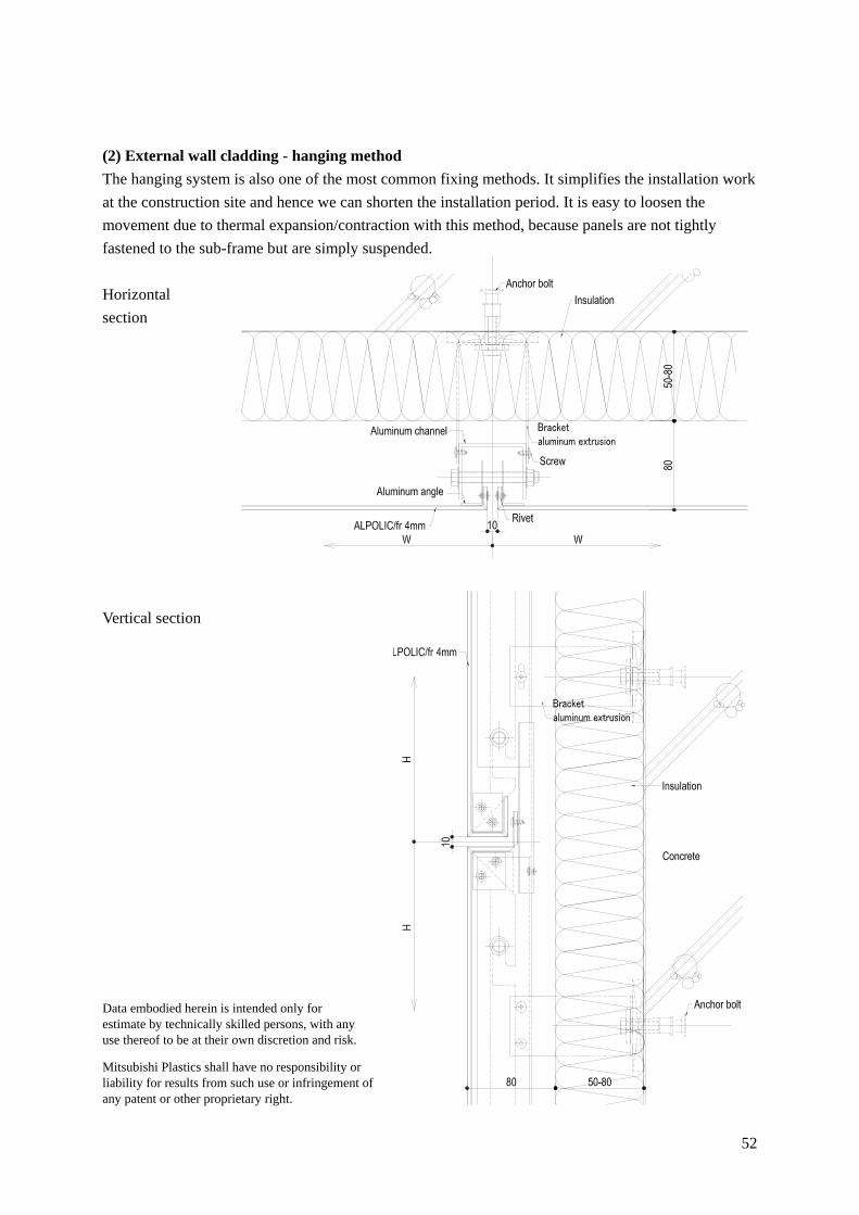
(2) External wall cladding - hanging method
The hanging system is also one of the most common fixing methods. It simplifies the installation work
at the construction site and hence we can shorten the installation period. It is easy to loosen the
movement due to thermal expansion/contraction with this method, because panels are not tightly
fastened to the sub-frame but are simply suspended.
Horizontal
section
Vertical section
Data embodied herein is intended only for estimate by technically skilled persons, with any use thereof to be at their own discretion and risk.
Mitsubishi Plastics shall have no responsibility or liability for results from such use or infringement of any patent or other proprietary right.

53
(3) External wall cladding - dry gasket joint
In this method, we use gaskets in the joints instead of sealants. The durability of EPDM gaskets is
comparable to that of the sealant, in addition, the gasket joint reduces the amount of dirt or stain on
ALPOLIC surface.
Horizontal
section
Vertical section
Data embodied herein is intended only for estimate by technically skilled persons, with any use thereof to be at their own discretion and risk.
Mitsubishi Plastics shall have no responsibility or liability for results from such use or infringement of any patent or other proprietary right.

54
(4) External wall cladding – narrow open joint
Generally, this kind of method is suitable for Stone and Timber-patterned ALPOLIC panels in which
narrow joints between the panels are aesthetically effective. According to need, we apply a sealing
material or EPDM gasket to the joints.
Horizontal
section
Vertical section
Data embodied herein is intended only for estimate by technically skilled persons, with any use thereof to be at their own discretion and risk.
Mitsubishi Plastics shall have no responsibility or liability for results from such use or infringement of any patent or other proprietary right.

55
(5) Roof covering
ALPOLIC has been used for roof covering in prestigious projects such as airports and stadiums. In
roof applications, we install a water gutter or waterproof sheets behind ALPOLIC panels so that leaked
water can drain outside.
Typical section
Gutter system
Data embodied herein is intended only for estimate by technically skilled persons, with any use thereof to be at their own discretion and risk.
Mitsubishi Plastics shall have no responsibility or liability for results from such use or infringement of any patent or other proprietary right.

56
(6) Back panel of glass curtain wall
Glass curtain walls sometimes need an opaque spandrel panel (back panel) behind glass for aesthetic
and energy-saving purpose. The spandrel back panels behind the glass must be very durable especially
to UV exposure, because it is hard to replace them after the building is completed. ALPOLIC is the
perfect material for such applications.
Horizontal section
Vertical
section
Data embodied herein is intended only for estimate by technically skilled persons, with any use thereof to be at their own discretion and risk.
Mitsubishi Plastics shall have no responsibility or liability for results from such use or infringement of any patent or other proprietary right.

57
(7) Sunshade or cornice
ALPOLIC is sometimes used for sunshade or the cornice of a building wall. In this type of application,
normally steel or aluminum frames are used as reinforcement behind ALPOLIC.
Typical section
A-A section
A
25
12
0
100205050
80
1000-2800
20
2015
A
Border frame of curtainwall
H-BeamSupport Framing
Water Gutter
ALPOLIC/fr 4mm
Welding
Steel bent
ALPOLIC/fr 4mm Sealing material
End capaluminum extrusion
20
20
15
25
20
20
20
5
Silicone sealant
Aluminum extrusion
End capaluminum sheet
Rivet
ALPOLIC/fr 4mm
Aluminum extrusion
Steel bentfor level adjusting
Welding
Support framing
Aluminum extrusion
Aluminum extrusionALPOLIC/fr 4mm Sealing material
Data embodied herein is intended only for estimate by technically skilled persons, with any use thereof to be at their own discretion and risk.
Mitsubishi Plastics shall have no responsibility or liability for results from such use or infringement of any patent or other proprietary right.

58
(8) Ceiling panel with non-penetrating rivet
When we use ALPOLIC for indoor ceilings or soffits, non-penetrating rivets simplify the panel details.
Non-penetrating rivets are usable only on low-gloss finishes (30% or less). If we use these rivets on
medium to high gloss products, the trail of the concealed rivet is visible from front. The design
strength of the non-penetrating rivet is approx. 300 N/piece not including the safety factor. Refer to
“Appendix 7: Modified non-penetrating rivet” in Section 4. In this method, we install fabricated
ALPOLIC panels on lightweight suspension bar ceiling systems.
40
25
30
20 20 PW, PH
PW+20, PH+20 8
3
4
5
6
1
2
7
1: Suspension bolt, 2: Hanger, 3: Double clip 4: Double bar, 6: Steel channel 40×20×1.6mm 5: Non-penetrating rivet and aluminum profile 7: Stiffener, aluminum square pipe 8: ALPOLIC/fr 4mm
Data embodied herein is intended only for estimate by technically skilled persons, with any use thereof to be at their own discretion and risk.
Mitsubishi Plastics shall have no responsibility or liability for results from such use or infringement of any patent or other proprietary right.

59
(9) Parapet and soffit, renovation
ALPOLIC is widely used for parapets and soffits in building renovation. ALPOLIC is used for the
water drip, parapet and soffit in the following detail.
Data embodied herein is intended only for estimate by technically skilled persons, with any use thereof to be at their own discretion and risk.
Mitsubishi Plastics shall have no responsibility or liability for results from such use or infringement of any patent or other proprietary right.
25 25 25
Approx. 1000mm
1
3
2
5
4
6
7
9 10
8
1: ALPOLIC/fr 4mm, water drip 2: Aluminum sub-structure 3: ALPOLIC/fr 4mm, parapet 4: Existing external wall 5: Level-adjustment and anchor 6: Suspension bolt 7: Aluminum support plate 8: Aluminum L-shaped support plate 9: ALPOLIC/fr 4mm, water drip 10: ALPOLIC/fr 4mm, eaves soffit

60
(10) Corporate shop front signboard This corporate signboard is a shop front sign of a countrywide newspaper company in Japan. The signboard has signs by 3M’s Scotchcal film. The aluminum flanges are coated with the same color as ALPOLIC.
Elevation
A A
B
B Approx. 4200 mm
Approx. 1200 mm
1. ALPOLIC 4mm having signs (logotype, letterings) by Scotchcal film
2. Aluminum flange coated with the same color of ALPOLIC
3. Water drip 4. Drain hole 5. Steel sub-structure, L-30×30, coated 6. Anchor 7. Stiffener, aluminum square pipe, 30×30×2 8. Corner support plate, aluminum L-40×40 9. Aluminum channel (top & bottom only) 10. VHB tape
B-B section
50 20
1
2
5
3
4
6
7
8
A-A section
2 1
10
7
9
Data embodied herein is intended only for estimate by technically skilled persons, with any use thereof to be at their own discretion and risk.
Mitsubishi Plastics shall have no responsibility or liability for results from such use or infringement of any patent or other proprietary right.

61
(11) Roof of pedestrian passage
ALPOLIC has been used as roof panels of public pathways and bus stations. Refer to an application
photograph in P. 11. ALPOLIC panels are just clamped between sub-frames and aluminum extrusions.
In most projects, the curving panels can be naturally curved without a mechanical bending.
Plan B-B section
C-C section
A-A section
Data embodied herein is intended only for estimate by technically skilled persons, with any use thereof to be at their own discretion and risk.
Mitsubishi Plastics shall have no responsibility or liability for results from such use or infringement of any patent or other proprietary right.
62
8. Overview of installation work
(1) General
Installation work accounts for a substantial part of the entire ALPOLIC work. Supposedly, the best
installation procedures will be chosen from many aspects including quality, construction period and its
cost. In this chapter, we would like to look over the basics of installation procedures of ALPOLIC,
taking a small to medium scale external cladding project as an example.
When we install fabricated panels at project site, we implement the installation work in accordance
with the drawings and specifications of the project. In the event that we find some discrepancy
between drawings and the actual conditions at project site, we have to report to and consult with the
project controller.
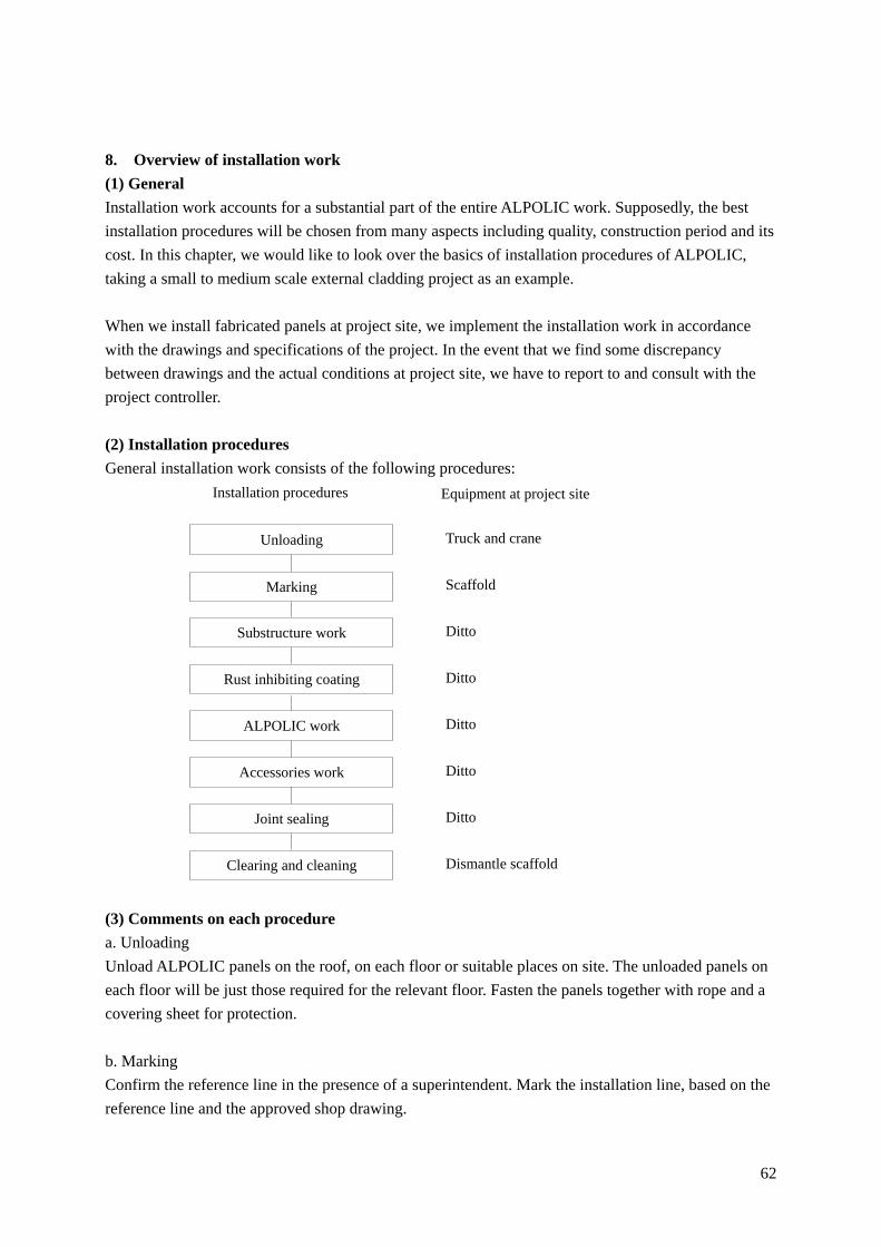
(2) Installation procedures
General installation work consists of the following procedures:
(3) Comments on each procedure
a. Unloading
Unload ALPOLIC panels on the roof, on each floor or suitable places on site. The unloaded panels on
each floor will be just those required for the relevant floor. Fasten the panels together with rope and a
covering sheet for protection.
b. Marking
Confirm the reference line in the presence of a superintendent. Mark the installation line, based on the
reference line and the approved shop drawing.
Scaffold
Ditto
Ditto
Ditto
Ditto
Ditto
Dismantle scaffold
Truck and crane
Equipment at project site
Unloading
Marking
Substructure work
Rust inhibiting coating
ALPOLIC work
Accessories work
Clearing and cleaning
Joint sealing
Installation procedures

63
c. Substructure work
In order to install the substructure, weld steel bracket pieces onto hole-in anchors (example of bracket:
L-50504mmt, L=70mm). Weld continuous steel angles onto the brackets (example of continuous
angle: L-40403mmt). All the angles will be finished with rust inhibiting coating, which conforms to
the project standard. To prevent fire during welding, pay attention to sparks that drop on the cover
sheet and veneer. During the substructure work, check the level with a flush thread and plumb-bob line,
or water level, if necessary.
d. Rust inhibiting coating
Apply rust inhibiting paint onto all the welded points including the back and edge. The paint and
coating thickness must conform to the project standard
e. ALPOLIC work
Mark the installation line in accordance with the shop drawing. Fix ALPOLIC panel onto the
substructure with self-tapping screws, 4mm in diameter, after confirming the position of the panel (left,
right, top and bottom). The fixing interval will be normally 300-400mm depending on the strength
calculation. After confirming the fixed conditions, peel off the protective film and clear the removed
film.
f. Accessories work
Bring the accessories to the scaffold passage, as indicated in the shop drawing. The quantity of
accessories brought to the scaffold passage must be kept to a minimum to avoid dropping and other
accidents. Lay large accessories diagonally on scaffold passage.
Mark the installation line onto the substructure to meet the position of the window frame. Fix the
accessory with self-tapping screws, 4mm in diameter, with @=300mm interval. After installation,
check the installed level and precision. After the check, peel off the protective film. Clear the removed
film.
g. Joint sealing
Use the sealing material as specified in the project and apply the joint design (width and height) as
instructed from the sealant manufacturer. Typical sealing work includes cleaning of the joints,
inserting back-up material, applying masking tape, applying primer, filling with sealant, tooling with
palette knife, removing masking film and curing. As improper sealing work will affect the appearance
and the waterproofing performance of the joint, the sealing work must be conducted exactly based on
the instructions from sealant manufacturer.
h. Clearing and cleaning
Clear and clean the working area everyday after work. Especially, when the work is complete in a
zone, clear, clean and transfer the area smoothly to the next location, in order to avoid hindering the
next stage. Collect and clear unnecessary remains to the dump point everyday or transport out of the

64
site immediately.
9. Touch-up coating method
When we need to repair scratches on the coating surface of ALPOLIC, we can repair (touch-up) them
at room temperature. We use an air-cured type of Lumiflon-based fluorocarbon paint for repair coating.
The air-cured type paint consists of 2 components: main agent and hardener. Mix them with 13:1 ratio
(main agent: hardener) and stir the mixture before use.
After application, the air-cured type paint will reach surface dry in 1 hour and will show a satisfactory
coating performance in a couple of weeks. However, the touched-up portion may show a slightly
different appearance, because the coating appearance depends on the coating method. Especially in
Metallic Colors and Sparkling Colors, even an exactly matched paint may show a slightly different
appearance. In Stone, Timber and Metal finishes, we use an intermediate solid color diluted with a
clear paint for touch-up. The suitable dilution rate is, depending on the color, 10-90% of clear content.
Regarding the touch-up procedures, refer to “Appendix 9: Touch-up coating method” in Section 4.
10. Cleaning method
(1) Removal of light surface soiling
Prior to applying a cleaner, we recommend a forceful water rinse cleaning from top to bottom. Low
water volume with moderate pressure is better than considerable water volume with little pressure.
Simultaneous physical rubbing is also effective. Use a soft sponge or soft rags fully soaked in water.
a. Apply a water rinse with moderate pressure to dislodge the soiling. If this does not remove the
soiling, test a simultaneous water rinse with a sponge. If the soiling is still adhering after dry, test a
diluted mild detergent.
b. When you use a diluted mild detergent, use it with soft sponges or soft rags. Wash the surface with
uniform pressure and clean the surface in a horizontal motion first and then in a vertical motion.
c. Minimize the drip and splash of the mild detergent and rinse the rundown immediately to avoid
streaking. Clean the surface from top to bottom and follow with a thorough rinse with clean water.
(2) Cleaning of medium to heavy surface soiling
In order to remove medium to heavy soiling caused by grease and sealing material, some type of
alcohol such as IPA (Isopropyl Alcohol), ethanol or N-hexane is used. Dilute these alcohols by 50%
with water. Strong solvents or solvents-containing cleaners may have a detrimental effect on the
coating surface. Do a spot test on a small unseen area. Wash the residues with mild soap and rinse with
water.
(3) Caution
a. Strong solvents and strong cleaner may cause damage to the coating. Do a spot test on a small
unseen area.

65
b. Avoid abrasive cleaner. Do not use household cleaners containing abrasives.
c. Do not rub excessively as it may change the coating appearance.
d. Avoid drips and splashes. Remove the rundown as soon as possible.
e. Avoid extremely high and low temperatures. Extremely high temperatures will accelerate the
chemical reaction, evaporate water from the solution and cause streaking. Extremely low
temperatures will result in a poor cleaning effect. Perform cleaning work on a shaded side of the
building under moderate temperatures.
f. Do not use paint removers, strong alkali or acid cleaners. Do not use strong organic solvents such
as MEK (Methyl Ethyl Ketone), MIBK (Methyl Isobutyl Ketone), Treclene (Tri-chloroethylene)
or thinner.
g. Make sure that cleaning sponges and rags are grit free.
h. Do not mix cleaners.
(4) Practical cleaning method
Cleaners and detergents are normally local products. A cleaner or a detergent widely available in one
country may not be available in another country. We attached an example of a practical cleaning
method in “Appendix 10: Example of practical cleaning method” in Section 4. To confirm the
harmlessness of your cleaner, contact local distributors or our office. We will perform a test with your
cleaner sample.
11. Panel dimension and tolerance
For your planning (design) work of fabrication and installation, we excerpt the panel dimensions and
tolerances here from the product specifications.
(1) Product dimension
ALPOLIC/fr ALPOLIC
Thickness 3mm 4mm 6mm 3mm 4mm 6mm
Weight 6.0 kg/m2 7.6 kg/m2 10.9 kg/m2 4.6 kg/m2 5.5 kg/m2 7.4 kg/m2
Width Note 1 965, 1270 or 1575mm (for user’s selection)
Length Less than 7200mm (for user’s selection)
Note 1: Custom width is available between 914 mm and 1575 mm subject to minimum quantity.
Contact local distributors or our sales office.
Note 2: (Edge condition) ALPOLIC has cut edges without aluminum sheet displacement or core
protrusion.
(2) Product tolerance
Width: ±2.0 mm
Length: ±4.0 mm
Thickness: ±0.2 mm in 3 and 4 mm thick, ±0.3 mm in 6 mm thick
Bow: Maximum 0.5% (5mm/m) of the length or width
Diagonal difference: Maximum 5.0 mm