Fabrication, Assembly & Installation Instructions
16
Last saved on 5/24/2011 Interior Daylighting Lightshelf Fabrication, Assembly & Installation Instructions
Transcript of Fabrication, Assembly & Installation Instructions

Last saved on 5/24/2011
Interior Daylighting Lightshelf
Fabrication, Assembly & Installation
Instructions

aaaaaaaaLLLLLLLLuuuuuuuummmmmmmmiiiiiiiinnnnnnnnaaaaaaaatttttttteeeeeeee LLLLiiiitttteeeeWWWWaaaavvvveeee Interior Daylighting Lightshelf Page 2 of 16
Table of Contents
General Construction Notes ............................................................................................. 3
Basic Members & Fasteners............................................................................................. 4
Fabrication/Assemble/Installation:
Fabrication
Fabrication IN-RIGGER............................................................................................. 7
Fabrication LITEWAVE............................................................................................. 9
Fabrication TRIM CAP.............................................................................................. 10
Installation
Installation IN-RIGGER .............................................................................................. 8
Installation LITEWAVE.............................................................................................. 9
Installation TRIM CAP.............................................................................................. 11
Maintenance ................................................................................................................... 15
Cleaning and Maintenance Guide – Reference Website..…...………………….……..15
Maintenance Guide …………………………………………..…...…………………..15
Cleaning and Maintenance Guide for Flurocryl®Coatings – Hardcopy.………..……15

aaaaaaaaLLLLLLLLuuuuuuuummmmmmmmiiiiiiiinnnnnnnnaaaaaaaatttttttteeeeeeee LLLLiiiitttteeeeWWWWaaaavvvveeee Interior Daylighting Lightshelf Page 3 of 16
GENERAL CONSTRUCTION NOTES
1. These drawings and notes cover typical conditions for this product. Due to
individual job requirements it is necessary to refer to Tubelite’s final distribution
drawings for supplemental information not covered by these instructions. Any conflict
or discrepancies must be clarified through Tubelite’s Engineering Department prior to
execution.
2. All framing shall be erected plumb and true in proper alignment and relation to
established lines and grades.
3. Any discrepancies found between Tubelite’s final distribution drawings, these
drawings and notes, and actual field conditions must be brought to the attention of
Tubelite’s Engineering Department for recommendation prior to execution.
4. Materials stored at the job site must be kept in a safe place removed from possible
damage by other trades. Store off the ground. Cardboard or paper wrapped materials
must be kept dry. Check arriving materials for quantity and keep record of where
various materials are stored.
5. All field welding must be adequately shielded to avoid any weld splatter on either
aluminum or glass. Results will be unsightly and may be structurally unsound. Advise
general contractor and other trades accordingly.
6. Coordinate protection of installed work with general contractor and/or other trades.
7. Coordinate sequence of other trades which affect framing installation with the
general contractor (e.g. fire proofing, back up walls, partitions, ceilings, mechanical
ducts, convectors, etc.).
8. General contractor should furnish and guarantee bench marks, offset lines and
opening dimensions. These items should be checked for accuracy before proceeding
with erection. Make certain that all adjacent substrate construction is in accordance with
the contract documents and/or approved shop drawings. If not, notify the general
contractor in writing before proceeding with installation, since this constitutes
acceptance of work by other trades. If pre-setting of anchorage is required, coordinate
with the general contractor and supervise the location.
9. Review shop drawings to become familiar with project-specific conditions.
10. All materials to be installed plumb, level and true with regard to established bench
marks and column center lines established by the general contractor and checked by the
slope wall contractor.

aaaaaaaaLLLLLLLLuuuuuuuummmmmmmmiiiiiiiinnnnnnnnaaaaaaaatttttttteeeeeeee LLLLiiiitttteeeeWWWWaaaavvvveeee Interior Daylighting Lightshelf Page 4 of 16
BASIC MEMBERS & FASTENERS
PARTS/SHAPES Description Part No.
LiteWave Aluminum
Extrusion
E6405
In-Rigger 36”
(for storefront application) P6411-0R
In-Rigger 30”
(for storefront application) P6412-0R
In-Rigger 24”
(for storefront application) P6407-0R
In-Rigger 18”
(for storefront application) P6413-0R

aaaaaaaaLLLLLLLLuuuuuuuummmmmmmmiiiiiiiinnnnnnnnaaaaaaaatttttttteeeeeeee LLLLiiiitttteeeeWWWWaaaavvvveeee Interior Daylighting Lightshelf Page 5 of 16
PARTS/SHAPES Description Part No.
In-Rigger 36”
(for curtainwall application) P6417-0R
In-Rigger 30”
(for curtainwall application) P6416-0R
In-Rigger 24”
(for curtainwall application) P6415-0R
In-Rigger 18”
(for curtain application) P6414-0R
Cap, Trim, Aluminum
Extrusion E6403

aaaaaaaaLLLLLLLLuuuuuuuummmmmmmmiiiiiiiinnnnnnnnaaaaaaaatttttttteeeeeeee LLLLiiiitttteeeeWWWWaaaavvvveeee Interior Daylighting Lightshelf Page 6 of 16
PARTS/SHAPES Description Part No.
Transition ‘I’ Aluminum
Extrusion
E6404
FASTENERS/TOOLS Description Part No.
Kit (3) PCS of S370 - Screw,
3/8-16 X 1” Button Socket
Head
P6405
S200 - Screw, #8-32 x 3/8”
Flat Head Phil Type F S200
Kit - (4) PCS of S200 -
Screw #8-32 x 3/8” Flat
Head Phil Type F & (2) PCS
P6409 Corner Key (.312
long)
P6408
Tool - Drill Fixture – In-
Rigger (Optional)
(for storefront application)
P6410
Tool - Drill Fixture – In-
Rigger (Optional)
(for curtainwall application)
P6418

aaaaaaaaLLLLLLLLuuuuuuuummmmmmmmiiiiiiiinnnnnnnnaaaaaaaatttttttteeeeeeee LLLLiiiitttteeeeWWWWaaaavvvveeee Interior Daylighting Lightshelf Page 7 of 16
Overview/Fabrication/Assembly/Installation
FABRICATION – In-Rigger
Fab Step #1a: Determine Horizontal Window DLOs (Day Light Openings);
Fab Step #1b: Determine In-Rigger location & LiteWave Cut Length.
Fab Step #1c Locate & Drill In-Rigger Mounting Holes - Using Drill Fixture locate & pre-
drill ¼” locator holes figure 1&2:
• Drill and 3/8-16 tap (3) places in mullion for In-Rigger mounting screws:
Figure 1 Figure 2
Figure 3

aaaaaaaaLLLLLLLLuuuuuuuummmmmmmmiiiiiiiinnnnnnnnaaaaaaaatttttttteeeeeeee LLLLiiiitttteeeeWWWWaaaavvvveeee Interior Daylighting Lightshelf Page 8 of 16
INSTALLATION – In-Rigger
Install Step #1a: Locate (1) In-Rigger per vertical mullion not to exceed 120” max. span
and Fastener Kit (P6408)
Install Step #1b: Install (1) fastener (P6405) into top tapped hole, allowing ½” clearance for
In-Rigger – as shown figure 4& 5.
Install Step #1c: Position & hang In-Rigger onto fastener as illustrated figures 5, & 6.
Install Step #1d: Install remaining (2) fasteners into In-Rigger. Tighten, but not over-tighten
causing thread strip out.
Figure 4 Figure 5 Figure 6
Figure 7

aaaaaaaaLLLLLLLLuuuuuuuummmmmmmmiiiiiiiinnnnnnnnaaaaaaaatttttttteeeeeeee LLLLiiiitttteeeeWWWWaaaavvvveeee Interior Daylighting Lightshelf Page 9 of 16
FABRICATION - LiteWave
Fab Step #2: Cutting E6405 LiteWave to length
• Cut to predetermined length required (per step #1 & 2 above) length equals In-rigger
hang on location to furthest opposite end location (not to exceed max extrusion length of
290”) Important - LiteWave extends beyond In-Rigger - not to exceed 1/2”.
NOTE: Linear alignment of single and multiple lightshelf units is very important. It is
recommended that alignment equipment be used to insure accuracy. Complete fabrication
and installation instructions should be reviewed prior to any fabrication, assembly or
installation activities.
For length of LiteWave extrusion (approx 290” max.), measure DLOs and
spans to determine optimum linear spans, not to exceed 120” between In-
Riggers.
INSTALLATION - LiteWave
Install Step #2a: Install LiteWaves Install LiteWave (E6405)
• Using LiteWaves cut to predetermined lengths (Fabrication Steps) locate first LiteWave
and place it onto the (2) corresponding ‘hooks’ closest to the glass on the bottom side of
the In-Rigger as illustrated – figure 8.
• LiteWave will hang in place on the In-Riggers while you get the next LiteWave and
repeat - installed in the same manner.
• NOTE: The last LiteWave installed may require a little additional pressure to lock into
place figures 9 & 10. Use non-marking mallet to tap into place.
Figure 8
Figure 10
Figure 9

aaaaaaaaLLLLLLLLuuuuuuuummmmmmmmiiiiiiiinnnnnnnnaaaaaaaatttttttteeeeeeee LLLLiiiitttteeeeWWWWaaaavvvveeee Interior Daylighting Lightshelf Page 10 of 16
• Install Step #2b: Install LiteWaves; the last LiteWave is now in place – if the last
LiteWave is loose, secure it at the outer edge of in-rigger using fastener (S200) as
illustrated figures 11 & 12; drill & tap to insure proper location and secure attachment.
• Important - LiteWave should not extend more than 1/2” beyond In-Rigger each end.
FABRICATION – Trim Cap
Fab Step #3 Trim Caps
End Trim Caps are cut to match In-Rigger depth with 45 degree cut on inside end corner (as
illustrated) (these are approx. nominal dimensions; please confirm for your installation):
• 18” In-Rigger uses approximately 19-3/4” long End Cap
• 24” In-Rigger uses approximately 25-3/4” long End Cap
• 30” In-Rigger uses approximately 31-3/4” long End Cap
• 36” In-Rigger uses approximately 37-3/4” long End Cap
S200
Figure 11

aaaaaaaaLLLLLLLLuuuuuuuummmmmmmmiiiiiiiinnnnnnnnaaaaaaaatttttttteeeeeeee LLLLiiiitttteeeeWWWWaaaavvvveeee Interior Daylighting Lightshelf Page 11 of 16
INSTALLATION - Trim Cap
Install Step #3a: (E6403)
IMPORTANT: fabricate end trim cap first, then with end trim caps located in place,
measure and cut front trim cap as noted.
Place fabricated front trim cap on bench face down, insert corner keys as shown and then
add end trim cap. Check corner for square-ness and fit-up. With corner together, drill two
holes and install self threading screws, one in each side of front trim cap as shown, into
corner key.
Drawing views of trim cap installation:
Figure 13
Figure 15
Figure 14

aaaaaaaaLLLLLLLLuuuuuuuummmmmmmmiiiiiiiinnnnnnnnaaaaaaaatttttttteeeeeeee LLLLiiiitttteeeeWWWWaaaavvvveeee Interior Daylighting Lightshelf Page 12 of 16
Install Step #3b: With end caps attached to front trim cap, locate and slide unit over
LiteWave ends and into place, snapping front trim over front ends of In-Riggers.
Install Step #3c: After cap has been located into place, drill & install self threading screw
(S200) through top side of cap and into In-Rigger as illustrated.
INSURE CLEAN SHARP
CORNERS
aaaaaaaaLLLLLLLLuuuuuuuummmmmmmmiiiiiiiinnnnnnnnaaaaaaaatttttttteeeeeeee LLLLiiiitttteeeeWWWWaaaavvvveeee Interior Daylighting Lightshelf Page 13 of 16
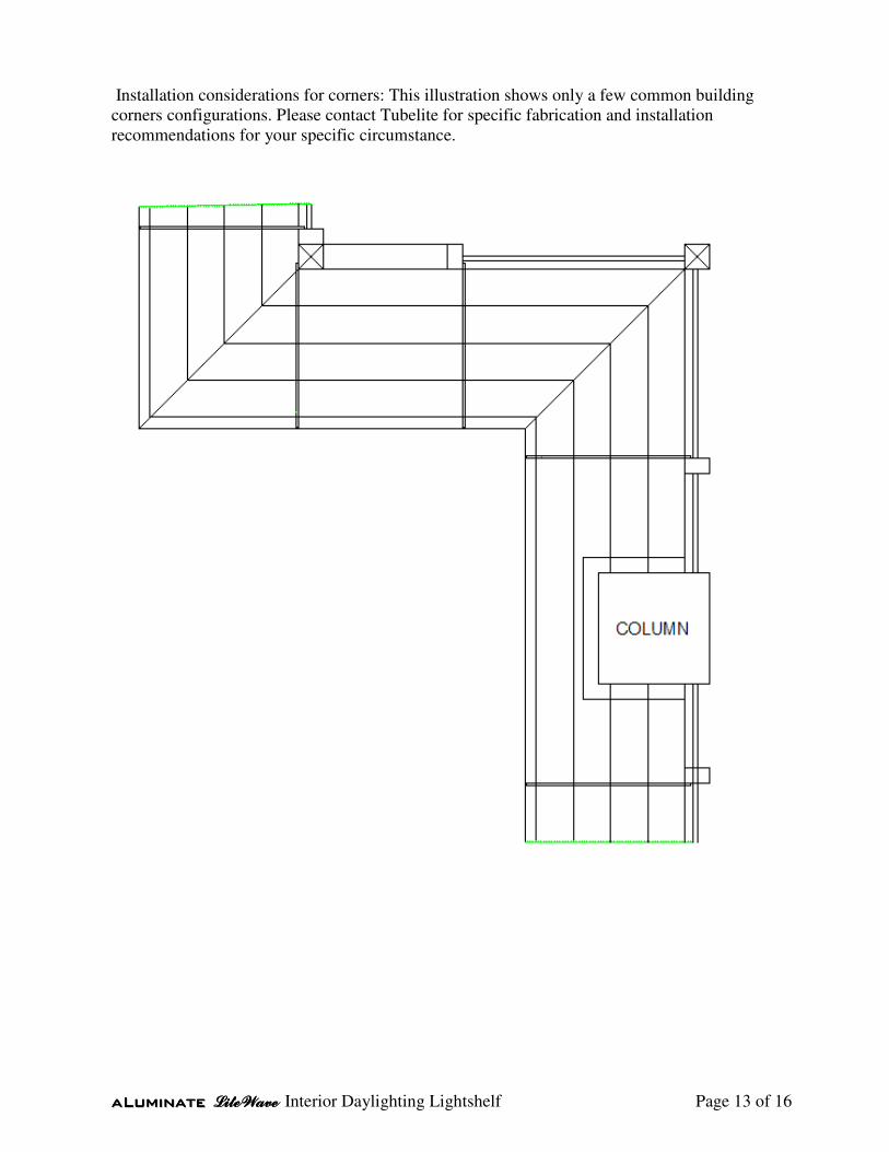
Installation considerations for corners: This illustration shows only a few common building
corners configurations. Please contact Tubelite for specific fabrication and installation
recommendations for your specific circumstance.

aaaaaaaaLLLLLLLLuuuuuuuummmmmmmmiiiiiiiinnnnnnnnaaaaaaaatttttttteeeeeeee LLLLiiiitttteeeeWWWWaaaavvvveeee Interior Daylighting Lightshelf Page 14 of 16
The Tubelite aLuminate LiteWave Light Shelf
Complete & Installed

aaaaaaaaLLLLLLLLuuuuuuuummmmmmmmiiiiiiiinnnnnnnnaaaaaaaatttttttteeeeeeee LLLLiiiitttteeeeWWWWaaaavvvveeee Interior Daylighting Lightshelf Page 15 of 16
Maintenance – Care & Consideration
• Cleaning and Maintenance Guide – Reference Website - Maintenance:
http://www.paintandcolor.com/pac/pdf/Cleaning_and_Maintenance_Guid
e_ for_Flurocryl_Coatings.pdf (or see below)
• Cleaning and Maintenance Guide for Flurocryl® Coatings In
cleaning this system three precautions should be observed:
1) Do not use abrasives (i.e., Comet cleanser), wire brushes, or similar cleaners or tools
which mechanically abrade the surface,
2) Prior to utilizing a household, commercial or industrial cleaning agent, the list of
ingredients must be reviewed to ensure that the cleaner is free from the solvents
discussed below, and
3) Cleaning agents should be tested in an isolated area before using on a large scale.
GROUP A: HOT OR COLD DETERGENT SOLUTIONS
A 5% solution in water of commonly used commercial and industrial detergents will
not have any deleterious effect on the Flurocryl surface. Cleaning with these solutions
should be followed by a thorough water rinse. Use a soft cloth for application of this
solution.
GROUP B: SOLVENTS
Most organic solvents are flammable and/or toxic, and must be handled accordingly.
Read the manufacturer’s Material Safety Data Sheets (MSDS). Keep away from open
flames, sparks, and electrical motors. Use adequate ventilation, protective clothing, and
goggles. The solvents listed below may be applied directly to the Flurocryl surface if
removed and dried within 5 minutes.
Solvent that may be used to remove non-water soluble deposits such as tar, grease, oil,
and graffiti from Flurocryl surfaces include; Alcohols - These alcohols have no
permanent effect on Flurocryl finishes: � Denatured alcohol (ethanol) � Isopropyl
alcohol (rubbing alcohol)
GROUP C: PETROLEUM SOLVENTS AND TURPENTINE
The solvents listed below may be applied direct to the Flurocryl surface, if removed
and dried within 15 minutes: � VM&P naphtha � Mineral spirits
The above solvents have no permanent effect on Flurocryl finishes

aaaaaaaaLLLLLLLLuuuuuuuummmmmmmmiiiiiiiinnnnnnnnaaaaaaaatttttttteeeeeeee LLLLiiiitttteeeeWWWWaaaavvvveeee Interior Daylighting Lightshelf Page 16 of 16
o CHEMICAL SOLUTIONS
Mildew: In areas subject to high humidity levels, dirt and spore deposits can permit
mildew growth to occur. The following solution is recommended to remove mildew
when necessary:
Laundry bleach (Clorox) at a reduction of 10 parts water to 1 part bleach.
Limit contact to 5 minutes and follow with a thorough water rinse.
Typical household cleaners that may be used directly on the Flurocryl system include:
409, Soft Scrub, Tilex, Pine-Sol & Lysol
o SOLVENTS NOT TO USE
The following solvents must not be utilized as cleaning agents, or components of
cleaning agents – use of these solvents will result in delamination of the Flurocryl film
from the aluminum substrate:
Xylene (Xylol), Toluene (Toluol), Perchlorethylene (Perclene), Trichlorethylene
(Triclene), Methyl ethyl ketone (MEK), Methyl isobutyl ketone (MIBK), Ethyl acetate
(Nail polish remover), Butyl acetate, Acetone, Paint/lacquer thinner, and Paint remover
o WARRANTY
Misuse or abuse of any cleaning agent will result in a voiding of warranty for the
surface affected.