SECTION 26 05 02 - cfpua.org
32
Date 1/1/21 Basic Electrical Work Cape Fear Public 26 05 02-1 Utility Authority SECTION 26 05 02 BASIC ELECTRICAL WORK PART 1 GENERAL ........................................................................................................................ 2 1.1 GENERAL PROVISIONS DESCRIPTION ...................................................................... 2 1.2 MATERIAL DESCRIPTIONS ........................................................................................... 3 1.3 STANDARD REFERENCES ........................................................................................... 5 1.4 GENERAL PROVISIONS QUALITY ASSURANCE........................................................ 6 1.5 MATERIALS QUALITY ASSURANCE ............................................................................ 6 1.6 GENERAL PROVISIONS SUBMITTALS ........................................................................ 7 1.7 MATERIAL SUBMITTALS ............................................................................................... 8 PART 2 PRODUCTS ..................................................................................................................... 9 2.1 MATERIAL ....................................................................................................................... 9 2.2 LOW-VOLTAGE ELECTRICAL POWER CONDUCTORS AND CABLES MATERIALS . .......................................................................................................................................... 9 2.3 GROUNDING AND BONDING MATERIALS ................................................................ 11 2.4 HANGERS AND SUPPORTS MATERIALS .................................................................. 12 2.5 RIGID CONDUITS MATERIALS ................................................................................... 13 2.6 RIGID CONDUITS ACCESSORIES .............................................................................. 14 2.7 RIGID CONDUITS IDENTIFICATION ........................................................................... 14 2.8 FLEXIBLE CONDUIT MATERIALS ............................................................................... 14 2.9 SEALED FITTINGS MATERIALS.................................................................................. 15 2.10 PULL, JUNCTION AND TERMINAL BOXES MATERIALS .......................................... 15 2.11 OUTLET BOXES MATERIALS...................................................................................... 16 2.12 IDENTIFICATION FOR ELECTRICAL SYSTEM MANUFACTURED UNITS .............. 17 2.13 IDENTIFICATION FOR ELECTRICAL SYSTEM FABRICATION ................................ 19 PART 3 EXECUTION .................................................................................................................. 19 3.1 GENERAL PROVISIONS INSPECTION ....................................................................... 19 3.2 GENERAL PROVISIONS INSTALLATION ................................................................... 20 3.3 GENERAL PROVISIONS FIELD QUALITY CONTROL ............................................... 20 3.4 LOW-VOLTAGE ELECTRICAL POWER CONDUCTORS AND CABLES INSTALLATION ............................................................................................................. 21 3.5 LOW-VOLTAGE ELECTRICAL POWER CONDUCTORS AND CABLES FIELD QUALITY CONTROL ..................................................................................................... 22 3.6 GROUNDING AND BONDING INSPECTION .............................................................. 22 3.7 GROUNDING AND BONDING EQUIPMENT GROUNDING ....................................... 23 3.8 GROUNDING AND BONDING FIELD QUALITY CONTROL ....................................... 23 3.9 HANGERS AND SUPPORTS INSTALLATION ............................................................ 23 3.10 RIGID CONDUITS INSTALLATION .............................................................................. 25 3.11 RIGID CONDUITS FIELD QUALITY CONTROL .......................................................... 27 3.12 FLEXIBLE CONDUITS INSTALLATION ....................................................................... 27 3.13 SEALED FITTING INSTALLATION ............................................................................... 27 3.14 PULL, JUNCTION AND TERMINAL BOXES INSTALLATION ..................................... 28 3.15 OUTLET BOXES INSTALLATION ................................................................................ 28 3.16 IDENTIFICATION FOR ELECTRICAL SYSTEMS INSTALLATION ............................ 29
Transcript of SECTION 26 05 02 - cfpua.org
Date 1/1/21 Basic Electrical Work Cape Fear Public 26 05 02-1 Utility Authority
SECTION 26 05 02
BASIC ELECTRICAL WORK
PART 1 GENERAL ........................................................................................................................ 2
1.1 GENERAL PROVISIONS DESCRIPTION ...................................................................... 2
1.2 MATERIAL DESCRIPTIONS ........................................................................................... 3
1.3 STANDARD REFERENCES ........................................................................................... 5
1.4 GENERAL PROVISIONS QUALITY ASSURANCE ........................................................ 6
1.5 MATERIALS QUALITY ASSURANCE ............................................................................ 6
1.6 GENERAL PROVISIONS SUBMITTALS ........................................................................ 7
1.7 MATERIAL SUBMITTALS ............................................................................................... 8
PART 2 PRODUCTS ..................................................................................................................... 9
2.1 MATERIAL ....................................................................................................................... 9 2.2 LOW-VOLTAGE ELECTRICAL POWER CONDUCTORS AND CABLES MATERIALS .
.......................................................................................................................................... 9
2.3 GROUNDING AND BONDING MATERIALS ................................................................ 11
2.4 HANGERS AND SUPPORTS MATERIALS .................................................................. 12
2.5 RIGID CONDUITS MATERIALS ................................................................................... 13
2.6 RIGID CONDUITS ACCESSORIES .............................................................................. 14
2.7 RIGID CONDUITS IDENTIFICATION ........................................................................... 14
2.8 FLEXIBLE CONDUIT MATERIALS ............................................................................... 14
2.9 SEALED FITTINGS MATERIALS.................................................................................. 15
2.10 PULL, JUNCTION AND TERMINAL BOXES MATERIALS .......................................... 15
2.11 OUTLET BOXES MATERIALS ...................................................................................... 16
2.12 IDENTIFICATION FOR ELECTRICAL SYSTEM MANUFACTURED UNITS .............. 17
2.13 IDENTIFICATION FOR ELECTRICAL SYSTEM FABRICATION ................................ 19
PART 3 EXECUTION .................................................................................................................. 19
3.1 GENERAL PROVISIONS INSPECTION ....................................................................... 19
3.2 GENERAL PROVISIONS INSTALLATION ................................................................... 20
3.3 GENERAL PROVISIONS FIELD QUALITY CONTROL ............................................... 20 3.4 LOW-VOLTAGE ELECTRICAL POWER CONDUCTORS AND CABLES
INSTALLATION ............................................................................................................. 21 3.5 LOW-VOLTAGE ELECTRICAL POWER CONDUCTORS AND CABLES FIELD
QUALITY CONTROL ..................................................................................................... 22
3.6 GROUNDING AND BONDING INSPECTION .............................................................. 22
3.7 GROUNDING AND BONDING EQUIPMENT GROUNDING ....................................... 23
3.8 GROUNDING AND BONDING FIELD QUALITY CONTROL ....................................... 23
3.9 HANGERS AND SUPPORTS INSTALLATION ............................................................ 23
3.10 RIGID CONDUITS INSTALLATION .............................................................................. 25
3.11 RIGID CONDUITS FIELD QUALITY CONTROL .......................................................... 27
3.12 FLEXIBLE CONDUITS INSTALLATION ....................................................................... 27
3.13 SEALED FITTING INSTALLATION ............................................................................... 27
3.14 PULL, JUNCTION AND TERMINAL BOXES INSTALLATION ..................................... 28
3.15 OUTLET BOXES INSTALLATION ................................................................................ 28
3.16 IDENTIFICATION FOR ELECTRICAL SYSTEMS INSTALLATION ............................ 29
Date 1/1/21 Basic Electrical Work Cape Fear Public 26 05 02-2 Utility Authority
PART 1 GENERAL
1.1 GENERAL PROVISIONS DESCRIPTION
A. Scope: 1. Contractor shall provide all labor, materials, equipment, and incidentals shown,
specified, and required to complete the electrical Work. 3. Demolition: Electrical demolition shall be in accordance with Section 02 41 00 –
Demolition. 3. Demolition: Responsibility for electrical demolition is indicated in Section 01 10 00 –
Summary. 4. Utility Companies:
a. Electric Utility Company: Perform the Work in connection with the electric service and utility metering in accordance with requirements of Duke.
B. Coordination: 1. Review installation procedures and schedules under other contracts and coordinate
with other contractors the installation of electrical items to be installed with or within formwork, walls, partitions, ceilings, and panels constructed by other contractors. a. Furnish as required to other contractors detailed drawings or sketches of the
locations of conduits and other built-in items. b. Coordinate with other contractors regarding progress of construction where
conduits and built-in items will be installed. Install conduits and built-in items in manner that does not delay work of other contractors.
2. Coordination and Intent of Electrical Drawings: a. Dimensions on Drawings related to equipment are based on equipment of
certain manufacturers. Verify the dimensions of equipment furnished to space available at the Site and allocated to the equipment.
b. Drawings show the principal elements of the electrical Work, and are not intended as detailed working drawings for the electrical Work. Drawings supplement and complement the Specifications and other Contract Documents relative to principal features of electrical systems.
c. Equipment and devices provided under this Contract shall be properly connected and interconnected with other equipment and devices for successful operation of complete systems, whether or not all connections and interconnections are specifically mentioned or shown in the Contract Documents.
d. Drawings are provided for Contractor’s guidance in fulfilling the intent of the Contract Documents. Contractor shall comply with Laws and Regulations, including safety and electrical codes, and provide materials, equipment, appurtenances, and specialty items necessary for complete and operable systems.
3. Obtain from Owner record drawings required to execute the Work. 4. Field Coordination:
a. Provide materials, equipment, and services to interface with existing circuits. Field-verify system and equipment requirements prior to modifying existing systems.
Date 1/1/21 Basic Electrical Work Cape Fear Public 26 05 02-3 Utility Authority
b. Coordinate the interface of equipment with Owner’s personnel and field conditions.
c. Field-compare existing starter and panel control circuit terminations from record documents with existing circuits.
d. Field-trace existing circuits as required to interface the equipment provided. e. Field-identify terminations for starters and panel controls for re-connection.
C. Related Sections: 1. Section 02 41 00, Demolition. 2. Section 03 05 00, Concrete. 3. Section 09 91 00, Paint and Protective Coatings. 4. Section 31 23 34, Excavation, Trenching, Dewatering and Backfilling.
D. Area Classifications: 1. Materials, equipment, and incidentals shall be suitable for the area classification(s)
shown, specified, and required. 2. Wet Locations: Comply with NEC and NEMA requirements for wet locations.
Enclosures in wet locations shall comply with NEMA 4 unless specified otherwise. 3. Corrosive Locations: Comply with NEC and NEMA requirements for corrosive
locations. Enclosures in corrosive locations shall conform to NEMA 4X requirements unless specified otherwise.
4. Hazardous Locations: Comply with NEC requirements for the Class and Division designated.
1.2 MATERIAL DESCRIPTIONS
A. Low-Voltage Electrical Power Conductors and Cables Scope: 1. Contractor shall provide all labor, materials, equipment, and incidentals shown,
specified, and required to furnish and install low-voltage conductors and cabling. 2. Types of cabling required include:
a. Insulated cable for installation in raceways. 3. Conductor type shall comply with the following:
a. VFD conductors (other than pump manufacturer cables): VFD cables. b. Other conductors: Single conductor copper cables.
B. Low-Voltage Electrical Power Conductors and Cables Related Sections: 1. This Section – Identification for Electrical Systems. 2. Section 31 23 34, Excavation, Trenching, Dewatering and Backfilling.
C. Grounding and Bonding Scope: 1. Contractor shall provide labor, materials, equipment, and incidentals as shown,
specified, and required to furnish and install complete grounding for electrical systems, structures, and equipment.
D. Hangers and Supports Scope: 1. Contractor shall provide all labor, materials, equipment, and incidentals as shown,
specified, and required to furnish and install hangers and supports for electrical systems.
Date 1/1/21 Basic Electrical Work Cape Fear Public 26 05 02-4 Utility Authority
2. Area Classifications: Materials shall by suitable for the area classification(s) shown or indicated on the Drawings, and specified in This Section, General Provisions Description.
E. Hangers and Supports Related Sections: 1. This Section, General Provisions Description. 2. This Section, Rigid Conduits.
F. Rigid Conduits Scope: 1. Contractor shall provide all labor, materials, equipment, and incidentals shown,
specified, and required to furnish and install conduit and fittings to form complete, coordinated and, for metallic raceways, grounded raceway systems.
2. When specific, detailed conduit routings for various systems are not shown on the Drawings, Contractor shall establish routings based on single-line, riser, and interconnection diagrams and other information on the Drawings. Contractor shall provide for the proper installation of conduits in each system.
G. Rigid Conduits Coordination: 1. Conduit runs shown are diagrammatic. Coordinate conduit installation with piping
and other systems and equipment and locate to avoid interferences. 2. For conduits to be embedded in concrete slabs, confirm adequate slab thickness
and coordinate location of conduits with placement of reinforcing steel, waterstops, expansion joints, and other features of the concrete slab.
H. Rigid Conduits Related Sections: 1. Section 31 23 34, Excavation, Trenching, Dewatering and Backfilling. 2. This Section, Hangers and Supports for Electrical Systems. 3. This Section, Identification for Electrical Systems.
I. Flexible Conduits Scope: 1. Contractor shall provide all labor, materials, equipment, and incidentals shown,
specified, and required to furnish and install flexible metallic conduit and fittings.
J. Sealed Fittings Scope: 1. Contractor shall provide all labor, materials, equipment, and incidentals as shown,
specified, and required to furnish and install conduit sealing fittings with sealing fiber and sealing compound.
K. Pull, Junction and Terminal Box Scope: 1. Contractor shall provide all labor, materials, equipment, and incidentals as shown,
specified, and required to furnish and install pull, junction, and terminal boxes.
L. Pull, Junction and Terminal Box Related Sections: 1. This Section, General Provisions Description. 2. This Section, Hangers and Supports for Electrical Systems. 3. This Section, Identification for Electrical Systems.
M. Outlet Boxes Scope:
Date 1/1/21 Basic Electrical Work Cape Fear Public 26 05 02-5 Utility Authority
1. Contractor shall provide all labor, materials, equipment, and incidentals as shown, specified, and required to furnish and install outlet boxes for mounting wiring devices and lighting fixtures.
N. Outlet Boxes Related Sections: 1. This Section, General Provisions Description. 2. This Section, Hangers and Supports for Electrical Systems. 3. This Section, Identification for Electrical Systems. 4. This Section, Low-Voltage Receptacles. 5. This Section, Snap Switches.
O. Identification for Electrical Systems Scope: 1. Contractor shall provide all labor, materials, equipment, and incidentals shown,
specified, and required to furnish and install identification for electrical apparatus and electrical Work.
P. Identification for Electrical Systems Related Sections: 1. This Section, Low Voltage Electrical Power Conductors and Cables.
1.3 STANDARD REFERENCES
A. Standards referenced for Low-Voltage Electrical Power Conductors and Cables are: 1. ANSI/NETA ATS, Acceptance Testing Specifications for Electrical Power Equipment
and Systems. 2. ASTM B3, Specification for Soft or Annealed Copper Wire. 3. ASTM B8, Specification for Concentric-Lay-Stranded Copper Conductors, Hard,
Medium-Hard or Soft. 4. UL 44, Thermoset-Insulated Wires and Cables. 5. UL 1277, Electrical Power and Control Tray Cables with Optional Optical-Fiber
Members.
B. Standards referenced for Grounding and Bonding are: 1. ANSI/NETA ATS, Acceptance Testing Specifications for Electrical Power Equipment
and Systems. 2. ASTM B8, Specification for Concentric-Lay-Stranded Copper Conductors, Hard,
Medium-Hard or Soft. 3. UL 467, Grounding and Bonding Equipment.
C. Standards referenced for Rigid Conduits are: 1. ANSI C80.5, Standard for Electrical Rigid Metal Steel Conduit – Aluminum (ERMC-
A). 2. ANSI/NEMA FB1, Fittings, Cast Metal Boxes, and Conduit Bodies for Conduit,
Electrical Metallic Tubing and Cable. 3. NEMA TC2, Electrical Polyvinyl Chloride (PVC) Conduit. 4. NEMA TC3, Polyvinyl Chloride (PVC) Fittings for Use with Rigid PVC Conduit and
Tubing. 5. UL 6A, Electrical Rigid Metal Conduit – Aluminum. 6. UL 514B, Conduit, Tubing, and Cable Fittings. 7. UL 651, Safety Schedule 40 and 80 Rigid PVC Conduit and Fittings. 8. UL 886, Outlet Boxes and Fittings for Use in Hazardous (Classified) Locations.
Date 1/1/21 Basic Electrical Work Cape Fear Public 26 05 02-6 Utility Authority
9. UL 1242, Electrical Intermediate Metal Conduit – Steel. 10. UL 2277, Flexible Motor Supply Cable and Wind Turbine Tray Cable.
D. Standards referenced for Flexible Conduits are: 1. UL 360, Liquid-Tight Flexible Metal Conduit.
E. Standards referenced for Sealed Fitting are: 1. UL 886, Outlet Boxes and Fittings for Use in Hazardous (Classified) Locations,
Class 1, Groups A, B, C and D and Class II, Groups E, F and G.
F. Standards referenced for Pull, Junction and Terminal Boxes in this Section are. 1. AASHTO, Standard Specifications for Highway Bridges. 2. UL 886, Outlet Boxes and Fittings for Use in Hazardous (Classified) Locations.
G. Identification for Electrical Systems Regulatory Requirements: Comply with the following: 1. NEC Article 110, Requirements for Electrical Installation. 2. NEC Article 210, Branch Circuits. 3. NEC Article 215, Feeders. 4. NEC Article 504, Intrinsically Safe Systems. 5. NEC Article 702, Optional Standby Systems. 6. 40 CFR 1910.145 (OSHA) – Specification for Accident Prevention Signs and Tags. 7. NFPA 70E, Electrical Safety in the Workplace.
1.4 GENERAL PROVISIONS QUALITY ASSURANCE
A. Qualifications: 1. Electrical Subcontractor:
a. Electrical Subcontractor shall have not less than five years ’ experience installing electrical systems of the types required for the Project.
b. Electrical Subcontractor shall possess a valid electricians’ and contractors’ license in the jurisdiction where the Site is located.
B. Component Supply and Compatibility: 1. Materials and equipment similar to each other shall be from the same manufacturer
for uniformity.
C. Regulatory Requirements: 1. Permits: Refer to the General Conditions, Supplementary Conditions, and other
parts of the Contract Documents for responsibilities relative to obtaining and paying for permits, licenses, and inspection fees.
1.5 MATERIALS QUALITY ASSURANCE
A. Low-Voltage Electrical Power Conductors and Cables Regulatory Requirements: Comply with the following: 1. NEC Article 300, Wiring Methods. 2. NEC Article 310, Conductors for General Wiring.
B. Grounding and Bonding Quality Assurance Regulatory Requirements 1. National Electrical Code, (NEC).
Date 1/1/21 Basic Electrical Work Cape Fear Public 26 05 02-7 Utility Authority
a. NEC Article 250, Grounding and Bonding.
C. Rigid Conduits Regulatory Requirements: Comply with the following: 1. NEC Article 344, Rigid Metal Conduit. 2. NEC Article 352, Rigid Nonmetallic Conduit.
D. Flexible Conduits Regulatory Requirements: Comply with the following: 1. NEC Article 350, Liquid-Tight Flexible Metal Conduit.
E. Sealed Fitting Regulatory Requirements: Comply with the following: 1. NEC Article 500, Hazardous (Classified) Locations.
F. Pull, Junction and Terminal Boxes Regulatory Requirements: 1. NEC Article 314, Outlet, Device, Pull and Junction Boxes; Conduit Bodies; Fittings;
and Handhole Enclosures.
G. Outlet Boxes Regulatory Requirements: 1. NEC Article 314, Outlet, Device, Pull and Junction Boxes; Fittings; and Handhole
Enclosures. 2. NEC Article 501, Class I locations. 3. UL 514A, Metallic Outlet Boxes. 4. UL 514B, Fittings for Conduit and Outlet Boxes.
1.6 GENERAL PROVISIONS SUBMITTALS
A. General: 1. To the extent practical, submit Shop Drawings and other Contractor submittals for
each Specification Section into the smallest number of submittals possible. Do not furnish partial submittals.
2. Review of equipment submittals does not relieve Contractor of responsibility for providing complete and successfully operating systems.
B. Action Submittals: Submit the following: 1. Shop Drawings:
a. Internal wiring diagram and drawings indicating all connections to components and numbered terminals for external connections.
b. Dimensioned plan, section, elevations, and panel layouts showing means for mounting, conduit connection, and grounding.
c. List of components including manufacturer’s name and catalog number (or part number) for each.
d. Point-to point interconnection wiring diagrams as specified for each component. 2. Product Data:
a. Manufacturer's name and product designation or catalog number. b. Electrical ratings. c. Manufacturer’s technical data and specifications. d. Manufacturer’s indication of compliance with applicable reference standards.
C. Informational Submittals: Submit the following: 1. Manufacturer’s Instructions:
a. Installation data and instructions.
Date 1/1/21 Basic Electrical Work Cape Fear Public 26 05 02-8 Utility Authority
b. Instructions for handling, starting-up, and troubleshooting. 2. Source Quality Control Submittals: Results for required shop testing. 3. Field Quality Control Submittals: Results for required field testing.
D. Closeout Submittals: Submit the following: 1. Record Documentation:
a. System Record Drawings: Include the following: 1) One-line wiring diagram of the electrical distribution system. 2) Actual, in-place conduit and cable layouts with schedule of conduit sizes
and number, and size of conductors. 3) Layouts of the power and lighting arrangements and the grounding system. 4) Control schematic diagrams, with terminal numbers and control devices
identified, for all equipment. b. Record documents shall indicate final equipment and field installation
information.
1.7 MATERIAL SUBMITTALS
A. Low-Voltage Electrical Power Conductors and Cables: 1. Action Submittals: Product Data: Manufacturer’s literature, specifications, and
engineering data for low volt insulated cable proposed for use. 2. Informational Submittals: Field Quality Control Submittals: Written results of field
insulation resistance tests.
B. Grounding and Bonding: 1. Action Submittals: Product Data: Manufacturer’s technical information for grounding
materials proposed for use. 2. Informational Submittals: Field Quality Control Submittals: Results of ground
resistance tests at each test point.
C. Hangers and Supports: 1. Action Submittals: Product Data:
a. Manufacturer’s name, product designation, and catalog number of each material item proposed for use.
b. Manufacturer’s specifications including material, dimensional and weight data, and load capacity for each supporting system component proposed for use.
c. Pictorial views and corresponding identifying text of each component proposed for installation.
2. Informational Submittals: Manufacturer’s installation instructions, including recommended tightening torque values for all nuts and bolts.
D. Rigid Conduits: 1. Action Submittals: Product Data: Manufacturer’s catalog cuts and product data for
conduit, fittings, and appurtenances. 2. Closeout Submittals: Record Drawings: Show actual routing of exposed and
concealed conduit runs in record documents in accordance with Section 01 78 39, Project Design Drawing Requirements.
E. Flexible Conduits:
Date 1/1/21 Basic Electrical Work Cape Fear Public 26 05 02-9 Utility Authority
1. Action Submittals: Product Data: Manufacturer’s literature and technical information for flexible conduit and fittings proposed for use.
F. Sealed Fitting: 1. Action Submittals: Product Data: Manufacturer’s literature and technical information
for sealing fittings, sealing fiber, and sealing compound proposed for use.
G. Pull, Junction and Terminal Boxes: 1. Action Submittals: Product Data: Manufacturer’s technical information for pull,
junction, and terminal boxes proposed for use.
H. Outlet Boxes: 1. Action Submittals: Product Data: Manufacturer’s technical information for outlet
boxes proposed for use.
I. Identification For Electrical Systems: 1. Action Submittals: Product Data: Manufacturer’s literature, cut sheets,
specifications, dimensions and technical data for all products proposed under this Section.
PART 2 PRODUCTS
2.1 MATERIAL
A. Performance Criteria: 1. Electrical equipment shall be capable of operating successfully at full-rated load,
without failure, with ambient outside air temperature of -30 degrees F to 104 degrees F and an elevation of 2000 feet above mean sea level.
2. Unless specified otherwise, electrical equipment shall have ratings based on 75 degrees C terminations.
B. Testing Laboratory Labels: Electrical material and equipment shall bear the label of Underwriters' Laboratories, Inc. or other nationally recognized, independent testing laboratory, where standards have been established and label service applies and approved by the Authority Having Jurisdiction.
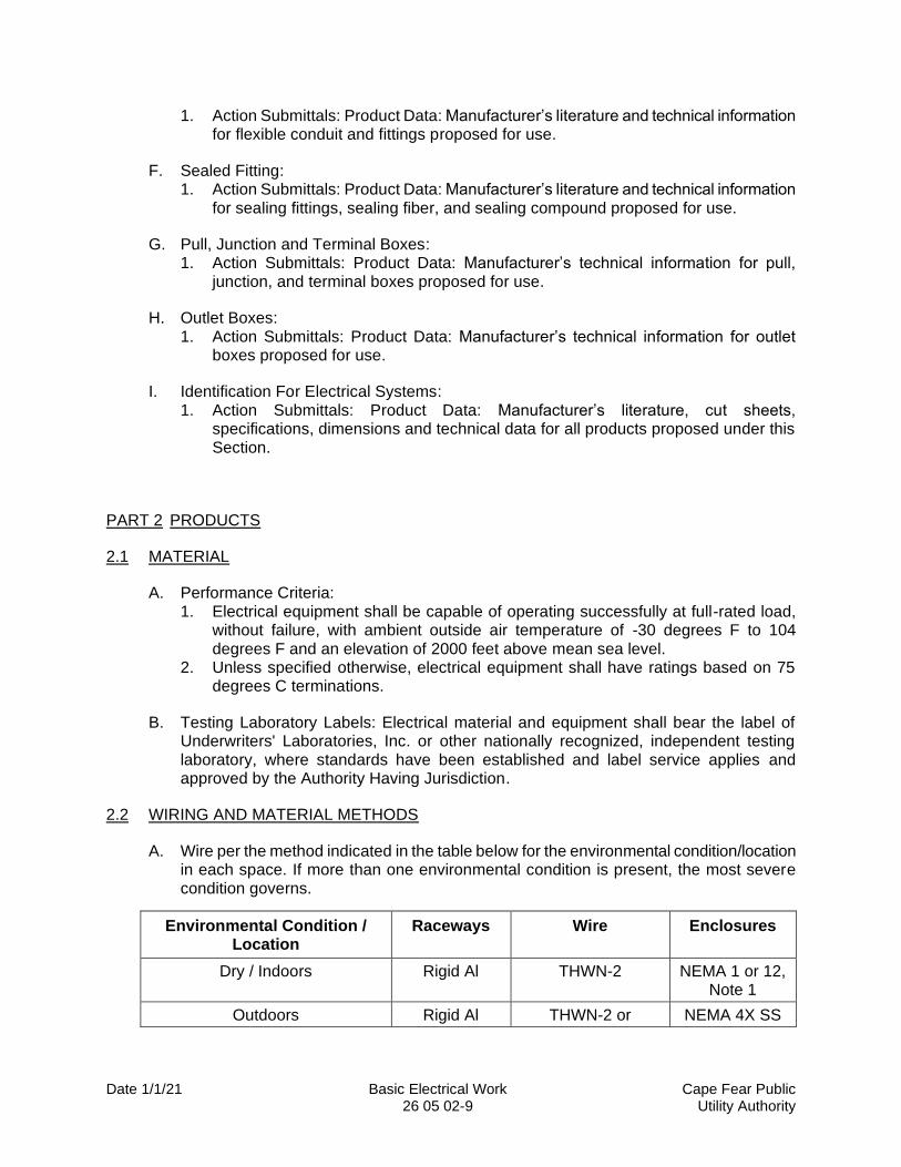
2.2 WIRING AND MATERIAL METHODS
A. Wire per the method indicated in the table below for the environmental condition/location in each space. If more than one environmental condition is present, the most severe condition governs.
Environmental Condition / Location
Raceways Wire Enclosures
Dry / Indoors Rigid Al THWN-2 NEMA 1 or 12, Note 1
Outdoors Rigid Al THWN-2 or NEMA 4X SS

Date 1/1/21 Basic Electrical Work Cape Fear Public 26 05 02-10 Utility Authority
XHHW-2
Outdoors VFD Circuits Rigid A XLPE VFD Cable
Underground PVC RHW-2 Note 2
Underground VFD Circuits PVC XLPE VFD Cable
Class I, Div 1 or 2 where raceway is continuous from
hazloc to equipment termination
Rigid Al, Note 3
RHW-2 or XHHW-2
NEMA 4X SS
Class I, Div 1 or 2 where raceway is routed from wetwell to cable tray with 5’ air gap to
electrical terminations
PVC Pump manufacturer cable
Note 1: NEMA 1 or 12 enclosures are acceptable where the building/enclosure is conditioned by an HVAC unit and where approved by CFPUA and recommended by the project engineer.
Note 2: Polymer concrete in soil. Cast iron in concrete or pavement.
Note 3: Where aluminum conduit is in contact with soil or concrete, coat with asphaltum or bitumastic type paint/coating.
2.3 LOW-VOLTAGE ELECTRICAL POWER CONDUCTORS AND CABLES MATERIALS
A. Insulated Cable In Raceways: 1. Manufacturers: Provide products of one of the following:
a. Southwire. b. The Okonite Company. c. American Insulated Wire. d. General Cable. e. Belden. f. Or equal.
2. Material: a. Single conductor copper cable complying with ASTM B3 and ASTM B8 with
flame-retardant, moisture- and heat-resistant insulation rated for 90 degrees C in dry or wet locations, listed by UL as Type XHHW-2, THWN-2 or RHW-2 complying with UL 44.
b. VFD Cable: Multiconductor copper cable complying with UL 2277; moisture-resistant XLPE insulation rated for 90 degrees C, 1000V minimum rating, ground conductor, overall copper shield, abrasion-, chemical-, and UV/sunlight-resistant PVC jacket.
3. Wire Sizes: Not smaller than No. 12 AWG for power and lighting and No. 14 AWG for 120-volt control circuits.
4. Stranding: 600-volt cable shall be stranded.
B. Cable Connectors, Solderless Type: 1. Products and Manufacturers: Provide products of one of the following:
a. T&B Sta-Kon. b. Burndy Hylug.
Date 1/1/21 Basic Electrical Work Cape Fear Public 26 05 02-11 Utility Authority
c. Or equal. 2. For wire sizes No. 4 AWG and above, use either compression type or bolted type
with silver-plated contact faces. 3. For wire sizes up to and including No. 6 AWG, use compression type. Alarm and
control wire shall be terminated using forked type connectors at terminal boards. 4. For wire sizes No. 250 KCMIL and larger, use connectors with at least two cable
clamping elements or compression indents and provision for at least two bolts for joining to apparatus terminal.
5. Properly size connectors to fit fastening device and wire size. Connectors shall be rated for 90 degree C, 600 volts.
C. Cable Splices: 1. Products and Manufacturers:
a. Pre-Insulated Solderless Compression Splices: Provide one of the following: 1) Ilsco. 2) NSI. 3) Or equal.
b. Spring Connectors: Provide one of the following: 1) Buchanan B-Cap. 2) T&B Wire Connector. 3) Or equal.
2. For wire sizes No. 8 AWG and larger, splices shall be made up with pre-Insulated solderless connectors with one spare port for future conductor connection.
3. For wire sizes No. 10 AWG and smaller, splices may be made up with pre-insulated spring connectors.
4. For wet locations, splices shall be waterproof. Spring connector splices shall be waterproofed with sealant filler.
5. Splices shall be suitably sized for cable, rated 90 degrees C, and 600 volts.
D. Wire and Cable Markers: 1. Provide wire and cable markers in accordance with This Section, Identification for
Electrical Systems.
E. Low-Voltage Electrical Power Conductors and Cables Source Quality Control: Factory Tests: Factory-test wire and cable in accordance with UL standards.
2.4 GROUNDING AND BONDING MATERIALS
A. Bare Ground Cable: 1. Manufacturers: Provide products of one of the following:
a. Cablec Corporation. b. General Cable Corporation. c. Southwire Cable Company. d. Or equal.
2. Material: Soft-drawn, bare copper stranded cable complying with ASTM B8. No. 4/0 AWG minimum size unless otherwise shown or indicated on the Drawings.
B. Ground Rods: 1. Manufacturers: Provide products of one of the following:
a. Copperweld, Bimetallics Division.
Date 1/1/21 Basic Electrical Work Cape Fear Public 26 05 02-12 Utility Authority
b. ITT Blackburn Company. c. Or equal.
2. Material: Copper-clad rigid steel rods, 3/4-inch diameter, ten feet long.
C. Grounding Connectors: 1. Products and Manufacturers: Provide one of the following:
a. Pressure Connectors: 1) O.Z./Gedney, Division of General Signal Corporation. 2) Burndy Corporation. 3) Or equal.
b. Welded Connections: 1) Cadweld by Erico Products, Incorporated. 2) Therm-O-Weld by Burndy Corporation. 3) Or equal.
2. Material: Pressure connectors shall be copper alloy castings, designed and fabricated specifically for items to be connected and assembled with Durium or silicone bronze bolts, nuts, and washers. Welded connections shall be by exothermic process utilizing molds, cartridges, and hardware designed specifically for connection to be made.
D. Ground Test Well 1. Manufacturer
a. Advanced Lightning Technology b. Or equal.
2. Diameter and Material: 12.75-inch outside diameter, Schedule 80 PVC. 3. Depth: Two feet. 4. Cover: Provide test well with cast iron cover marked, “Ground” with cast iron ring to
support lid.
E. Ground system components shall comply with UL 467.
2.5 HANGERS AND SUPPORTS MATERIALS
A. Manufacturers: Provide products of one of the following: 1. B-Line. 2. Kindorf. 3. Unistrut 4. Or equal.
B. Strut, Fittings, and Accessories: 1. General
a. Unless otherwise shown or indicated, strut shall be 1-5/8 inches by 1-5/8 inches stainless steel. Double struts shall be two pieces of the same strut, welded back-to-back at the factory.
b. Attachment holes, when required, shall be factory-punched on hole centers approximately equal to the cross-sectional width and shall be 9/16-inch diameter.
c. Fittings, braces, brackets, hardware, and accessories shall be Type 316 stainless steel.
d. Strut nuts shall be spring captured Type 316 stainless steel.
Date 1/1/21 Basic Electrical Work Cape Fear Public 26 05 02-13 Utility Authority
e. Square and round washers shall be Type 316 stainless steel. 2. Strut shall be 12 gauge Type 316 stainless steel.
C. Hanger Rods: 1. Material: Stainless steel. 2. Size: Not less than ⅜-inch diameter, unless otherwise shown on the Drawings or
specified.
D. Beam Clamps for Attaching Threaded Rods or Bolts to Beam Flanges for Hanging Struts or Conduit Hangers: Beam clamps shall be stainless steel equipped with stainless steel square-head set screw, and shall include threaded hole sized for attaching the all-thread rod or threaded bolt.
E. Miscellaneous Hardware: 1. Bolts, screws, and washers shall be stainless steel. 2. Hex Nuts: Shall be stainless steel and include nylon inserts.
2.6 RIGID CONDUITS MATERIALS
A. Aluminum Conduit, Elbows, and Couplings: 1. Manufacturers: Provide products of one of the following:
a. Allied Tube and Conduit. b. Wheatland Tube Company. c. Or equal.
2. Material: Rigid, heavy-wall aluminum, smooth interior, tapered threads and carefully reamed ends; ¾-inch NPS minimum size.
B. Metallic Conduit Fittings, and Outlet Bodies: 1. Manufacturers: Provide products of one of the following:
a. Crouse-Hinds Company. b. Appleton Electric Company. c. Or equal.
2. Material and Construction: Aluminum bodies and covers consistent with conduit material. Units shall be threaded type with five full threads. Materials shall comply with ANSI/NEMA FB1 and be listed by UL. Do not use “LB” fittings. Use type “LBD” fittings where use of fittings is unavoidable.
3. Use: Conduits shall be gasketed and watertight in hazardous, wet, and corrosive locations.
C. Non-metallic Conduit and Fittings: 1. PVC Plastic Conduit:
a. Manufacturers: Provide products of one of the following: 1) Amoco Chemicals Corp. 2) Carlon Electrical Products. 3) Or equal.
b. Material: PVC, rated for 90 degrees C, complying with NEMA TC3 and UL 514B and 651. 1) Exposed: Schedule 80. 2) Concealed: Schedule 40. 3) Underground: Schedule 40.
Date 1/1/21 Basic Electrical Work Cape Fear Public 26 05 02-14 Utility Authority
c. Fittings: Form elbows, bodies, terminations, expansions, and fasteners of same material and manufacturer as base conduit. Provide cement by same manufacturer as base conduit.
D. Conduit Hubs: 1. Manufacturers: Provide products one of the following.
a. Myers Electrical Products Company. b. Or equal.
2. Material: Threaded conduit hub, vibration-proof, weatherproof, with captive O-ring seal, aluminum with insulated throat and bonding screw.
3. Use: Provide for all conduit terminations to boxes, cabinets, and other enclosures in areas designated as wet locations.
E. Conduit Bushings and Locknuts: 1. Manufacturers: Provide products one of the following:
a. O-Z/Gedney. b. Appleton Electric Company. c. Or equal.
2. Insulated Bushings: aluminum body with plastic liner. Threaded type with steel clamping screw. Provide with bronze grounding lug, as required.
3. Locknuts: aluminum for all diameters. 4. Use: Provide for all conduit terminations to boxes, cabinets and other enclosures
except threaded type in areas designated as dusty locations.
2.7 RIGID CONDUITS ACCESSORIES
A. Fasteners: To the extent possible, fastener material shall be consistent with conduit material. Fasten raceway systems to supporting structures using the following: 1. To Wood: Wood screws. 2. To Hollow Masonry Units: Toggle bolts. 3. To Brick Masonry: Expansion bolts by Price, or equal. 4. To Concrete: Anchors. 5. To Steel: Beam clamps in accordance with This Section, Hangers and Supports for
Electrical Systems.
B. Duct Sealing Compound 1. Soft, fibrous, slightly tacky, non-hardening sealing compound. 2. Remains workable at all temperatures. 3. Manufacturer:
a. Type DUX by O-Z/Gedney. b. Or equal.
2.8 RIGID CONDUITS IDENTIFICATION
A. Warning Tape: Where underground, provide warning tape in accordance with This Section, Identification for Electrical Systems.
2.9 FLEXIBLE CONDUIT MATERIALS
A. Flexible Conduit:
Date 1/1/21 Basic Electrical Work Cape Fear Public 26 05 02-15 Utility Authority
1. Material: Flexible aluminum core with smooth, abrasion-resistant, liquid-tight, polyvinyl chloride cover. Continuous copper ground built in for sizes ¾-inch through 1.25-inch. Material shall be UL-listed.
2. Products and Manufacturers: Provide one of the following: a. Anaconda Sealtite Type EFL by Anamet Electrical, Inc. b. Liquatite Type ALT. by Electric-Flex Company. c. Or equal.
B. Flexible Conduit Fittings: 1. Material and Construction: Aluminum. Fittings shall adapt the conduit to standard
threaded connections, shall have an inside diameter not less than that of the corresponding standard conduit size and shall be UL listed.
2. Manufacturers: Provide products of one of the following: a. Crouse-Hinds Company. b. Appleton Electric Company. c. Or equal.
3. Use: Provide for connections to transformers or motorized equipment in non-hazardous areas.
2.10 SEALED FITTINGS MATERIALS
A. Manufacturers: Provide products of one of the following: 1. Crouse Hinds Company. 2. Appleton Electric Company. 3. Or equal.
B. Materials and Construction: 1. Aluminum. 2. Ample opening with threaded closure for access to conduit hub for making dam. 3. In corrosive locations, fittings shall include factory-applied 40-mil PVC coating. 4. Construct fitting to allow 40 percent cross-sectional fill.
C. Sealing fiber for forming the dam within the hub and sealing compound shall be suitable for use with fittings furnished, and shall be products of fitting manufacturer.
D. Sealing fitting, fiber, and sealing compound shall conform to UL 886.
2.11 PULL, JUNCTION AND TERMINAL BOXES MATERIALS
A. Pull, Junction, and Terminal Boxes: 1. General – Applicable to All Boxes:
a. Description and Performance Criteria: 1) Located indoors in prefabricated FRP shelters: NEMA 4X, 316 stainless
steel. 2) Located indoors in prefabricated, precast concrete enclosures: NEMA 1
when HVAC is provided for the enclosure and approved by CFPUA and recommended by the Engineer. Otherwise, enclosure shall be NEMA 4X, 316 stainless steel.
3) Located outdoors: NEMA 4X, 316 stainless steel.
Date 1/1/21 Basic Electrical Work Cape Fear Public 26 05 02-16 Utility Authority
4) In slabs or pavement potentially subject to vehicular traffic: Flush-mounted, cast iron pullboxes. Boxes and covers shall be constructed for H-20 loading in accordance with AASHTO Standard Specifications for Highway Bridges.
b. Manufacturers: Provide products of one of the following: 1) Appleton Electric Company. 2) Crouse-Hinds Company. 3) Hoffman Engineering Company. 4) Or equal.
c. Terminal strips and terminal blocks in terminal boxes shall be mounted on terminal box sub-panels.
d. Identification: Boxes shall be identified in accordance with This Section, Identification for Electrical Systems.
2. Materials and Construction - Wet, Corrosive, or Hazardous Locations: a. Rating:
1) Pull boxes in wet, corrosive, or outdoor areas shall be NEMA 4X. 2) Boxes for areas classified as hazardous locations, where required by NEC,
shall be explosion-proof and comply with UL 886. b. Material: Copper-free aluminum alloy or Type 316 stainless steel. c. Gasket:
1) Provide neoprene gaskets for wet and corrosive locations. 2) Gaskets shall be an approved type designed for the purpose. Improvised
gaskets are not acceptable. d. Access: Stainless steel cover bolts. e. Features:
1) External mounting lugs. 2) Drilled and tapped conduit holes. 3) Boxes where conduits enter building or structure below grade shall have
1/4-inch drain hole at bottom of the box. 4) Provide threaded connections for explosion proof boxes.
B. Terminal Blocks: 1. Products and Manufacturers: Provide one of the following:
a. Allen-Bradley Company, Bulletin, Model 1492. b. General Electric Company, Model CR151K. c. Or equal.
2. Material and Construction: a. NEMA-rated nylon modular terminal blocks. b. 600-volt rated. c. Control and alarm circuit terminals shall be screwed type with permanently
affixed numeric identifiers beside each connection. d. Power terminals shall be copper and rated for the circuit ampacity.
2.12 OUTLET BOXES MATERIALS
A. Device Boxes: 1. Manufacturers: Provide products of one of the following:
a. Crouse-Hinds Company. b. Appleton Electric Company. c. Or equal.
Date 1/1/21 Basic Electrical Work Cape Fear Public 26 05 02-17 Utility Authority
2. Material: a. In Wet Locations: Cast aluminum. b. Cast boxes shall be hub-type and include external mounting lugs. c. Metallic outlet boxes shall comply with UL 514A. d. Fittings for outlet boxes shall comply with UL 514B.
3. Cover Plates: a. Located indoors: Type 302 stainless steel alloy. b. Located outdoors: Cast aluminum. c. Stainless steel screws and hardware.
2.13 IDENTIFICATION FOR ELECTRICAL SYSTEM MANUFACTURED UNITS
A. Engraved Identification Devices (Nameplates and Legend Plates): 1. Nameplates:
a. Laminated thermoset plastic, 1/16-inch thick, engraved condensed block black lettering on white background, square corners, and beveled front edges, or match existing.
b. Size: As required. c. Letter Size: Minimum 3/16-inch.
2. Legend Plates: a. Legend plates for pushbuttons, pilot lights, selector switches, and other panel-
mounted devices shall be large size with dimensions of approximately 2-7/16 inches wide by 2-13/32 inches tall (Allen Bradley large automotive size), plastic, custom engraved with black letters on white background. 1) Provide standard-size legend plates where devices are mounted on motor
control centers and spacing of devices precludes using automotive-size legend plates.
b. Lettering size and line weight shall be the same for all legend plates on the same panel or enclosure. Maximum size shall be ¼-inch and minimum size shall be ⅛-inch.
3. Attach engraved nameplates with high-performance, double-coated tape with adhesive, 3M #06383 or equal.
B. Safety Signs and Voltage Markers: 1. Cable Tray Safety Signs:
a. Products and Manufacturers: Provide one of the following: 1) B-302-86139 by Brady. 2) Or equal.
b. Cable tray safety signs shall be pressure-sensitive vinyl conforming to 40 CFR 1910.145, 5 inches by 3.5 inches in size, and shall read, “DANGER – HIGH VOLTAGE”
2. Low-Voltage Safety Signs: a. Products and Manufacturers: Provide one of the following:
1) B-302-86060 by Brady. 2) Or equal.
b. Low voltage safety signs shall be pressure-sensitive vinyl complying with 40 CFR 1910.145, five inches by 3.5 inches in size, and shall read, “DANGER – 480 VOLTS”.
3. Low-Voltage Markers: a. Products and Manufacturers: Provide one of the following:
Date 1/1/21 Basic Electrical Work Cape Fear Public 26 05 02-18 Utility Authority
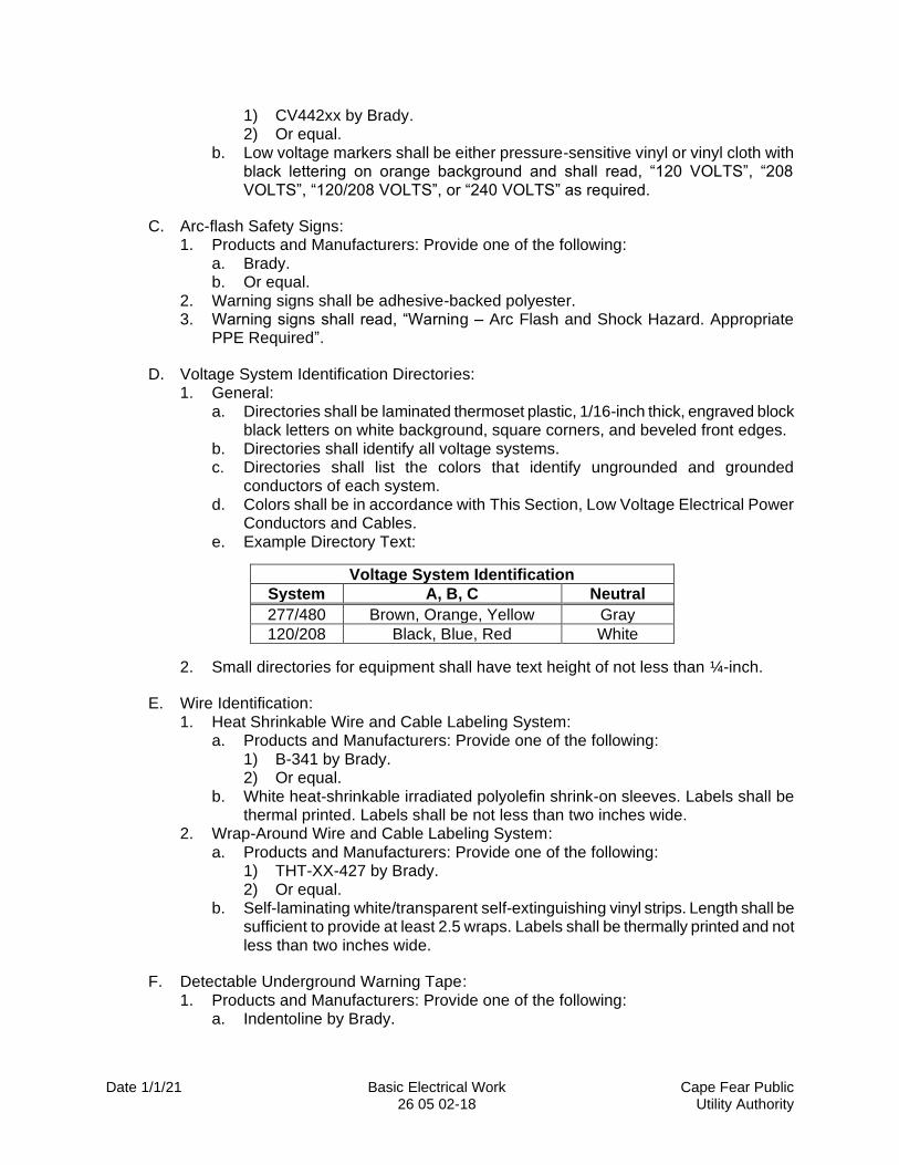
1) CV442xx by Brady. 2) Or equal.
b. Low voltage markers shall be either pressure-sensitive vinyl or vinyl cloth with black lettering on orange background and shall read, “120 VOLTS”, “208 VOLTS”, “120/208 VOLTS”, or “240 VOLTS” as required.
C. Arc-flash Safety Signs: 1. Products and Manufacturers: Provide one of the following:
a. Brady. b. Or equal.
2. Warning signs shall be adhesive-backed polyester. 3. Warning signs shall read, “Warning – Arc Flash and Shock Hazard. Appropriate
PPE Required”.
D. Voltage System Identification Directories: 1. General:
a. Directories shall be laminated thermoset plastic, 1/16-inch thick, engraved block black letters on white background, square corners, and beveled front edges.
b. Directories shall identify all voltage systems. c. Directories shall list the colors that identify ungrounded and grounded
conductors of each system. d. Colors shall be in accordance with This Section, Low Voltage Electrical Power
Conductors and Cables. e. Example Directory Text:
Voltage System Identification
System A, B, C Neutral
277/480 Brown, Orange, Yellow Gray
120/208 Black, Blue, Red White
2. Small directories for equipment shall have text height of not less than ¼-inch.
E. Wire Identification: 1. Heat Shrinkable Wire and Cable Labeling System:
a. Products and Manufacturers: Provide one of the following: 1) B-341 by Brady. 2) Or equal.
b. White heat-shrinkable irradiated polyolefin shrink-on sleeves. Labels shall be thermal printed. Labels shall be not less than two inches wide.
2. Wrap-Around Wire and Cable Labeling System: a. Products and Manufacturers: Provide one of the following:
1) THT-XX-427 by Brady. 2) Or equal.
b. Self-laminating white/transparent self-extinguishing vinyl strips. Length shall be sufficient to provide at least 2.5 wraps. Labels shall be thermally printed and not less than two inches wide.
F. Detectable Underground Warning Tape: 1. Products and Manufacturers: Provide one of the following:
a. Indentoline by Brady.
Date 1/1/21 Basic Electrical Work Cape Fear Public 26 05 02-19 Utility Authority
b. Or equal. 2. Material: Polyethylene or polyester with detectable metal core and polyester
underlaminate. 3. Width: Two inches. 4. Color and Labeling: Yellow or red with permanently imprinted black letters:
“CAUTION – Buried Electric Line”, repeated continuously over full length of tape.
G. Thermal Printing System: 1. Utilize thermal transfer process to provide non-smearing labels and markers. 2. Wire and Cable Markers:
a. Portable, Products and Manufacturers: Provide one of the following: 1) TLS2200 by Brady. 2) Or equal.
b. Desktop, Products and Manufacturers: Provide one of the following: 1) 200M by Brady. 2) Or equal.
3. Cable Markers: a. Portable, Products and Manufacturers: Provide one of the following:
1) Handimark by Brady. 2) Or equal.
b. Desktop, Products and Manufacturers: Provide one of the following: 1) Labelizer PLUS by Brady. 2) Or equal.
H. Generator System Warning Signs: 1. Generator warning signs shall be labeled in accordance with NEC Article 702. 2. Material, Colors, Letters: Plastic with white letters on red background. Letters shall
be not less than ⅜-inch high. 3. Attachment: Use stainless steel self-tapping screws. 4. Location warning sign shall read, “WARNING – THIS SITE EQUIPPED WITH A
DIESEL DRIVEN STAND-BY GENERATOR”. 5. Generator ground warning sign shall read, “WARNING – GENERATOR
GROUNDED CIRCUIT CONDUCTOR IS CONNECTED TO THE GROUNDING ELECTRODE CONDUCTOR IN THIS ENCLOSURE. DO NOT OPERATE GENERATOR WHILE EITHER CONDUCTOR IS DISCONNECTED TO AVOID SEVERE SHOCK HAZARD AND POSSIBLE EQUIPMENT DAMAGE. REMOVAL OF THIS CONNECTION COULD RESULT IN ELECTRIC SHOCK EVEN WHILE NOT OPERATING, PROCEED WITH EXTREME CAUTION.”
2.14 IDENTIFICATION FOR ELECTRICAL SYSTEM FABRICATION
A. Engraved Identification Devices (Nameplates and Legend Plates): 1. Nameplate and legend plate text is preliminary and subject to change pending final
review and approval of nomenclature by Engineer after start-up and testing.
PART 3 EXECUTION
3.1 GENERAL PROVISIONS INSPECTION
Date 1/1/21 Basic Electrical Work Cape Fear Public 26 05 02-20 Utility Authority
A. Examine conditions under which Work will be performed and notify Engineer in writing of conditions detrimental to the proper and timely completion of the Work. Do not proceed with Work until unsatisfactory conditions are corrected.
3.2 GENERAL PROVISIONS INSTALLATION
A. General: 1. Install materials and equipment in accordance with the Contract Documents, Laws
and Regulations, approved (and accepted, as applicable) Shop Drawings and other Contractor submittals, and manufacturer’s recommendations.
2. Provide tools and equipment required to trace circuits necessary for proper execution of the Work.
3. Define and identify all wiring, circuit terminations, and equipment to be modified to ensure proper interface of components. The Contract Price includes all costs associated with field services specified for a complete and functional system.
B. Staging, Sequencing, and Coordination with Existing Facilities: 1. Schedule, sequence, and install materials and equipment in accordance with
Section 01 14 16 – Coordination with Owner’s Operations 2. Perform the Work in a manner that will not interfere with the existing equipment and
facilities or cause interruption of the functions of the Site, unless specified otherwise or otherwise allowed by Owner.
3. When operation of existing facilities and Site is disrupted due to Contractor’s operations, comply with Section 01 14 16 – Coordination with Owner’s Operations, unless otherwise allowed by Owner.
4. Where the Work ties in with existing installations, take precautions and provide safeguards in connecting the Work to existing operating circuits to prevent interruption to existing circuits. Connection of Work to existing circuits shall be performed in the presence of Owner and Engineer.
5. Interruptions of existing circuits, not addressed in Section 01 14 16, Coordination with Owner’s Operations, shall be coordinated with the Owner who will determine the length of time a circuit may be de-energized to maintain the Owner’s processes in dependable and safe operation.
3.3 GENERAL PROVISIONS FIELD QUALITY CONTROL
A. Field Quality Control – General: 1. Perform field quality control for electrical Work in accordance with the Contract
Documents.
B. Site Tests: 1. Prior to requesting certificate of Substantial Completion, demonstrate to Engineer
that electrical systems and electrically-operated equipment installed or modified under the Contract operates in accordance with the Contract Documents and operates as required
2. Perform the following operational tests on electrical systems: a. Operate power circuits to verify proper operation and connection to electrical
systems materials and equipment, including mechanical key-interlocks for circuit breakers.
Date 1/1/21 Basic Electrical Work Cape Fear Public 26 05 02-21 Utility Authority
b. Remove and re-apply power supply to automatic transfer equipment to verify operation. Activate standby power systems to verify their automatic start-up, proper de-energization, and cool down upon resumption of normal power supply.
c. Operate control circuits, including pushbuttons, indicating lights, and similar devices, to verify proper connection and function. Operate all devices, such as pressure switches, flow switches, and similar devices, to verify that shutdowns and control sequences operate as required.
d. Operate lighting systems and receptacle devices to verify proper operation and connections.
3. Prepare and submit report on the equipment demonstration and operating field quality control tests. Report shall include complete information on the tests performed and results.
C. Manufacturer’s Services: 1. Furnish at the Site qualified, factory-trained representative(s) of equipment
manufacturers for the services indicated in the Contract Documents.
3.4 LOW-VOLTAGE ELECTRICAL POWER CONDUCTORS AND CABLES INSTALLATION
A. Install cables complete with proper terminations at both ends. Check and correct for proper phase sequence and proper motor rotation.
B. Pulling: 1. Use insulating types of pulling compounds containing no mineral oil. 2. Pulling tension shall be within limits recommended by wire and cable manufacturer. 3. Use dynamometer where mechanical means are used. 4. Cut off section subject to mechanical means.
C. Bending Radius: Limit to minimum of six times cable overall diameter.
D. Slack: Provide maximum slack at all terminal points.
E. Splices: 1. Where possible, install cable continuous, without splice, from termination to
termination. All splices not specifically indicated on the drawings shall require approval of the Engineer.
2. Where required, splice as shown and also where required for cable installation. Splices below grade, in manholes, handholes, and wet locations shall be waterproof.
3. Splices are not allowed in conduits.
F. Identification: 1. Identify conductors in accordance with This Section, Identification for electrical
Systems. 2. Identify power conductors by circuit number and phase at each terminal or splice
location. 3. Identify control and status wiring using numeral tagging system.
G. Color-code power cables as follows: 1. No. 8 AWG and Smaller: Provide colored conductors.
Date 1/1/21 Basic Electrical Work Cape Fear Public 26 05 02-22 Utility Authority
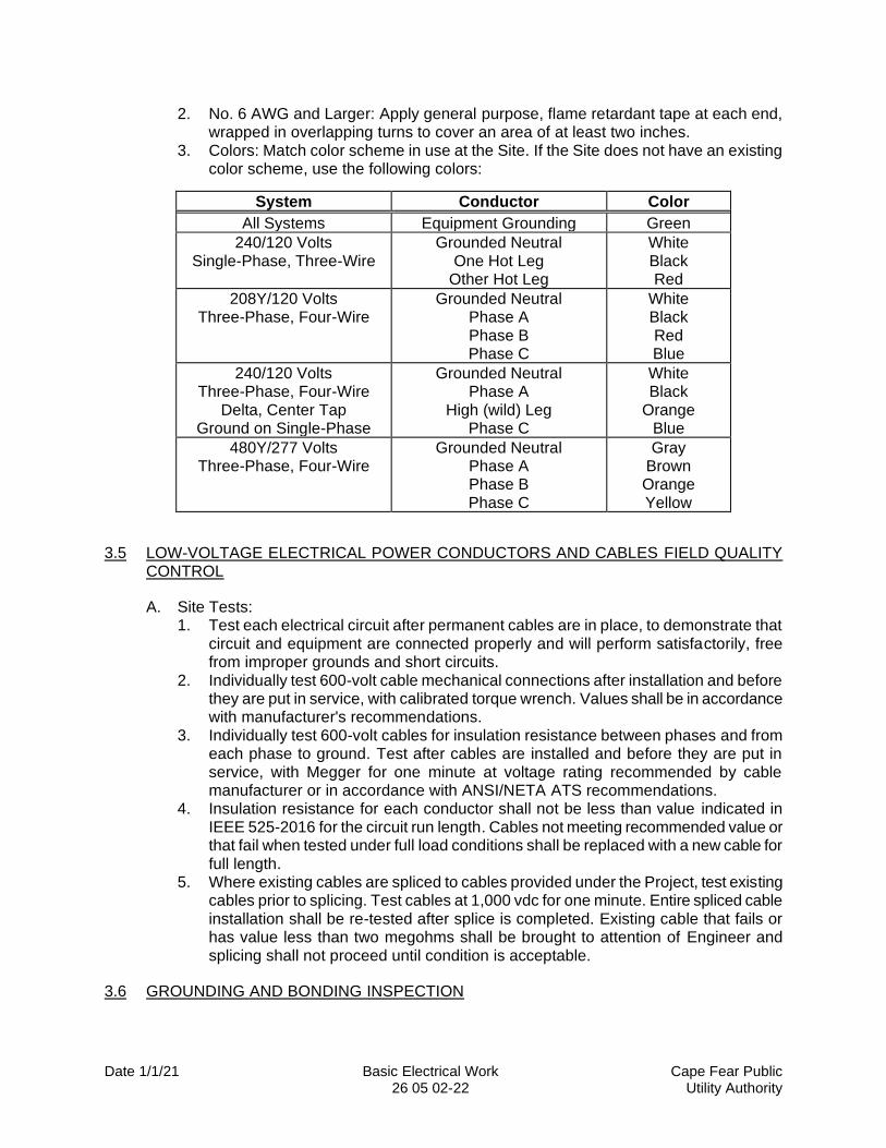
2. No. 6 AWG and Larger: Apply general purpose, flame retardant tape at each end, wrapped in overlapping turns to cover an area of at least two inches.
3. Colors: Match color scheme in use at the Site. If the Site does not have an existing color scheme, use the following colors:
System Conductor Color
All Systems Equipment Grounding Green
240/120 Volts Single-Phase, Three-Wire
Grounded Neutral One Hot Leg
Other Hot Leg
White Black Red
208Y/120 Volts Three-Phase, Four-Wire
Grounded Neutral Phase A Phase B Phase C
White Black Red Blue
240/120 Volts Three-Phase, Four-Wire
Delta, Center Tap Ground on Single-Phase
Grounded Neutral Phase A
High (wild) Leg Phase C
White Black
Orange Blue
480Y/277 Volts Three-Phase, Four-Wire
Grounded Neutral Phase A Phase B Phase C
Gray Brown Orange Yellow
3.5 LOW-VOLTAGE ELECTRICAL POWER CONDUCTORS AND CABLES FIELD QUALITY CONTROL
A. Site Tests: 1. Test each electrical circuit after permanent cables are in place, to demonstrate that
circuit and equipment are connected properly and will perform satisfactorily, free from improper grounds and short circuits.
2. Individually test 600-volt cable mechanical connections after installation and before they are put in service, with calibrated torque wrench. Values shall be in accordance with manufacturer's recommendations.
3. Individually test 600-volt cables for insulation resistance between phases and from each phase to ground. Test after cables are installed and before they are put in service, with Megger for one minute at voltage rating recommended by cable manufacturer or in accordance with ANSI/NETA ATS recommendations.
4. Insulation resistance for each conductor shall not be less than value indicated in IEEE 525-2016 for the circuit run length. Cables not meeting recommended value or that fail when tested under full load conditions shall be replaced with a new cable for full length.
5. Where existing cables are spliced to cables provided under the Project, test existing cables prior to splicing. Test cables at 1,000 vdc for one minute. Entire spliced cable installation shall be re-tested after splice is completed. Existing cable that fails or has value less than two megohms shall be brought to attention of Engineer and splicing shall not proceed until condition is acceptable.
3.6 GROUNDING AND BONDING INSPECTION
Date 1/1/21 Basic Electrical Work Cape Fear Public 26 05 02-23 Utility Authority
A. Examine conditions for the Work and notify Engineer in writing of conditions detrimental to proper and timely completion of the Work. Do not proceed with Work until unsatisfactory conditions are corrected.
3.7 GROUNDING AND BONDING EQUIPMENT GROUNDING
A. Ground electrical equipment in compliance with Laws and Regulations and the Contract Documents.
B. Equipment grounding conductors shall be bare stranded copper cable of adequate size installed in conduit where required for mechanical protection. Ground conductors, pulled into conduits with non-grounded conductors, shall be insulated. Insulation shall be green.
C. Control panels grounding conductors shall be insulated stranded copper cable of adequate size.
D. Connect ground conductors to conduit with copper clamps, straps, or with grounding bushings.
E. Connect to piping with copper clamps. Use copper bonding jumpers on gasketed joints.
F. Connect to equipment by means of lug compressed on cable end. Bolt lug to equipment frame using holes or terminals provided on equipment specifically for grounding. Do not use hold-down bolts. Where grounding provisions are not included, drill suitable holes in locations recommended by equipment manufacturer or designated by Engineer.
G. Connect to motors by bolting directly to motor frames, not to soleplates or supporting structures.
H. Connect to service water piping by means of copper clamps. Use copper bonding jumpers on gasketed joints.
I. Scrape bolted surfaces clean and coat with conductive oxide-resistant compound.
J. Connect grounding electrode conductors to ground rods and rebar with exothermic welds.
3.8 GROUNDING AND BONDING FIELD QUALITY CONTROL
A. Site Tests: 1. Test completed grounding systems for resistance to ground using an electrical
three-terminal ground resistance tester or clamp-on ground resistance tester. Test all grounded cables and metal parts for continuity of connection. Notify Engineer and Owner two weeks in advance for witness testing.
2. Grounding system maximum resistance shall not exceed five ohms under normally dry conditions when measured by resistance tester. Resistance values above five ohms shall be brought to Engineer’s attention. Provide additional ground rods as required to attain a resistance to ground of less than five ohms for each ground grid.
3.9 HANGERS AND SUPPORTS INSTALLATION
Date 1/1/21 Basic Electrical Work Cape Fear Public 26 05 02-24 Utility Authority
A. Inspection: Examine conditions under which the Work will be installed and notify Engineer in writing of conditions detrimental to the proper and timely completion of the Work. Do not proceed with the Work until unsatisfactory conditions are corrected.
B. Provide hangers and supports for electrical systems with necessary channels, fittings, brackets, and related hardware for mounting and supporting materials and equipment. Provide anchor systems, concrete inserts, and associated hardware for proper support of electrical systems.
C. Install equipment and devices on hangers and supports as shown on the Drawings, as specified, and as required.
D. Install hangers and supports level, true, free of rack, and parallel and perpendicular to building walls and floors, so that the hangers and supports are installed in a neat, professional, workmanlike manner.
E. Coordinate installation of hangers and supports with equipment, cabinets, consoles, panels, enclosures, boxes, conduit, cable tray, wireway, busway, cablebus, piping, ductwork, lighting fixtures, and other systems and equipment. Locate hangers and supports clear of interferences and access ways.
F. Anchor Bolts, Expansion Anchors, and Concrete Inserts: Shall be in accordance with the requirements of this Section.
G. Mounting of Conduit: 1. Provide space of not less than 1/4-inch between conduit surfaces and abutting or
near surfaces except struts, cable trays, steel beams, and columns. 2. Fasten conduit to struts, cable trays, steel beams, and columns using specified
clamps and straps as shown, specified, and required. 3. Devices shall be compatible with size of conduit and type of support. Following
installation, size identification shall be visible and legible. 4. Install conduit supports and fasteners in accordance with This Section, Rigid
Conduits.
H. Supports for Cabinets, Consoles, Panels, Enclosures, and Boxes: 1. Freestanding: Unless otherwise specified or shown on the Drawings, provide
supports for floor-mounted equipment, cabinets, consoles, panels, enclosures, and boxes. Such supports shall be 3.5-inch high concrete equipment base with a 45 degree chamfered edge. Base shall extend two inches beyond outside dimensions of equipment on all sides.
2. Wall-Mounted: a. Provide space not less than 1/4-inch between cabinets, consoles, panels,
enclosures, and boxes and the surface on which each is mounted. Provide non-metallic or stainless steel spacers as required.
b. Do not mount equipment, enclosures, panels, and boxes directly to beams or columns. Mount struts to beams or columns using beam clamps, and mount equipment, enclosures, panels, and boxes to the struts.
3. Floor Stand Rack: a. Where equipment, cabinets, consoles, panels, enclosures, and boxes cannot
be wall-mounted, provide an independent floor stand rack.

Date 1/1/21 Basic Electrical Work Cape Fear Public 26 05 02-25 Utility Authority
b. Floor stand rack shall consist of struts, plates, brackets, connection fittings, braces, accessories, and hardware assembled in a rigid framework suitable for mounting of intended materials and equipment.
c. Provide floor stand racks with brackets and bases for rigidly-mounting the framework to the ceiling or floor, as applicable; or equip floor stand racks with beam clamps, angle plates, washers, and bolts for fastening to beam flanges, as applicable.
d. When equipment, cabinets, consoles, panels, enclosures, and boxes weigh more than 100 pounds: 1) Main vertical supports of floor stand rack assemblies shall be back-to-back
struts. 2) Bracing, clamping and anchoring of each floor stand rack shall be sufficient
to ensure rigidity of the floor stand rack with the intended equipment, enclosures, conduit, cable tray, busway, cablebus, and wireway installed. Floor stand racks shall not be deflected more than ⅛-inch by a 100-pound force applied at any point on the floor stand rack in any direction.
I. Drilling into beams or columns is not allowed unless authorized by Engineer.
J. Tighten nuts and bolts to the manufacturer’s recommended torque values.
K. Field Cutting: 1. Cut edges of strut and hanger rod shall have rounded corners, edges beveled, and
burrs removed. If field cutting the strut is required, use clean, sharp, dedicated tools. Remove oil, shavings, and other residue of cuttings prior to installation.
3.10 RIGID CONDUITS INSTALLATION
A. Inspection: Examine conditions under which the Work will be performed and notify Engineer in writing of conditions detrimental to proper and timely completion of the Work. Do not proceed with installation until unsatisfactory conditions are corrected.
B. Install in accordance with Laws and Regulations.
C. Supports: 1. Rigidly support conduits by clamps, hangers, or Unistrut-type channels. Conduit
supports and accessories shall be in accordance with This Section, Hangers and Supports for Electrical Systems.
2. Support single conduits by means of one-hole pipe clamps in combination with one-screw back plates, to raise conduits from the support surface. Support multiple runs of conduits on trapeze type hangers.
D. Fastenings: Fasten raceway systems rigidly and neatly to supporting structures using specified materials.
E. Exposed Conduit: 1. Install parallel or perpendicular to structural members or walls. 2. Where possible, run in groups. Provide conduit racks of suitable width, length, and
height, arranged to suit field conditions. Provide support every ten feet, minimum. 3. Install on structural members in protected locations.
Date 1/1/21 Basic Electrical Work Cape Fear Public 26 05 02-26 Utility Authority
4. Locate clear of interferences. 5. Provide six inches of clearance from hot fluid lines and 1/4-inch from walls. 6. Install vertical runs plumb. Unsecured drop length shall not exceed 12 feet.
F. Underground Conduits: 1. Install individual, underground conduits minimum of 20 inches below grade, unless
otherwise shown or indicated. 2. Perform excavation, bedding, backfilling, and surface restoration, including
pavement replacement where required, in accordance with Section 31 23 34, Excavation, Trenching, Dewatering and Backfilling.
3. Install warning tape 12 inches below finished grade over buried conduits.
G. Empty Conduits: 1. Install nylon pull wire in each empty conduit and cap conduits not terminating in
boxes with permanent fittings designed for the purpose.
H. Field Bends: No indentations. Diameter of conduit shall not vary more than 15 percent at bends.
I. Joints: 1. Apply conductive compound to joints before assembly. 2. Make up joints tight and, for metallic raceways, ground thoroughly. 3. Use standard tapered pipe threads for conduit and fittings. 4. Cut conduit ends square and ream to prevent damaging wire and cable. 5. Use full threaded couplings. Split couplings are not allowed. 6. Use strap wrenches and vises to install conduit. Replace conduit with wrench marks.
J. Terminations: 1. Install insulated bushings on conduits entering boxes or cabinets, except when
threaded hubs are used. 2. Provide locknuts on both inside and outside of enclosure, except when threaded
hubs are used. 3. Use of bushings in lieu of locknuts is not allowed. 4. Install conduit hubs on conduits entering boxes or cabinets in wet and corrosive
areas.
K. Moisture Protection: 1. Plug or cap conduit ends at time of installation to prevent entrance of moisture and
foreign materials. 2. Underground and embedded conduit connections shall be watertight. 3. Drainage: Conduit runs shall be fully drainable. Avoid pockets or depressions in
conduit runs. 4. Seal conduit openings within control and instrumentation panels and distribution
equipment with duct sealing compound to provide watertight seal.
L. Corrosion Protection: 1. Dissimilar Metals:
a. Prevent occurrence of electrolytic action between dissimilar metals.
Date 1/1/21 Basic Electrical Work Cape Fear Public 26 05 02-27 Utility Authority
b. Do not use copper products in connection with aluminum, and do not use aluminum in locations subject to drainage of copper compounds on bare aluminum.
c. Back paint aluminum in contact with masonry or concrete with two coats of aluminum-pigmented bituminous paint.
M. Reused Existing Conduits: 1. Pull rag swab through conduits to remove water and to clean conduit prior to
installing new cable. 2. Repeat swabbing until all foreign material is removed. 3. Pull mandrel through conduit, if necessary, to remove obstructions.
N. Core drill for individual conduits passing through existing concrete slabs and walls. Notify Engineer in writing in advance of core drilling. Prior to core drilling, drill sufficient number of small exploratory holes to establish that the area to be core drilled is free of existing embedded conduits. Seal spaces around conduit as specified herein.
O. Non-metallic Conduit: 1. Install in accordance with manufacturer’s recommendations. 2. Provide manufacturer’s recommended adhesives or sealants for watertight
connections. 3. Transition to PVC-coated rigid steel conduit before making turn up to enclosures.
3.11 RIGID CONDUITS FIELD QUALITY CONTROL
A. Site Tests: 1. Test conduits by pulling through each conduit a cylindrical mandrel with length not
less than two pipe inside diameters, having an outside diameter equal to 90 percent of conduit’s inside diameter.
2. Repair or replace conduits that do not successfully pass testing, and re-test.
3.12 FLEXIBLE CONDUITS INSTALLATION
A. Inspection: Examine conditions under which the Work will be installed and notify Engineer in writing of conditions detrimental to proper and timely completion of the Work. Do not proceed with the Work until unsatisfactory conditions are corrected.
B. Install at motors, transformers, field instruments, and equipment subject to vibration or require movement for maintenance purposes. Provide necessary reducer where equipment furnished cannot accept ¾-inch diameter flexible conduit. Limit flexible conduit length to three feet maximum.
C. Install in conformance with the Laws and Regulations.
3.13 SEALED FITTING INSTALLATION
A. Inspection: Examine conditions under which the Work is to be installed and notify Engineer in writing of conditions detrimental to the proper and timely completion of the Work. Do not proceed with the Work until unsatisfactory conditions are corrected.
Date 1/1/21 Basic Electrical Work Cape Fear Public 26 05 02-28 Utility Authority
B. Install for hazardous locations as required by Laws and Regulations and as shown.
C. Provide fittings for proper use relative to mounting position.
D. Use oversized fittings with reducing bushings when necessary to maintain cable fill requirements of the conduit system.
3.14 PULL, JUNCTION AND TERMINAL BOXES INSTALLATION
A. Inspection: Examine conditions under which the Work will be installed and notify Engineer in writing of conditions detrimental to proper and timely completion of the Work. Do not proceed with the Work until unsatisfactory conditions are corrected.
B. Mount boxes so that sufficient access and working space is provided and maintain clearance of not less than 1/4-inch from walls.
C. Securely fasten boxes to walls or other structural surfaces on which boxes are mounted. Provide independent supports that comply with This Section, Hangers and Supports for Electrical Systems, where boxes will not be mounted on walls or other structural surface.
D. Install pull boxes where shown or indicated, and provide pull boxes where one or more of the following conditions exist: 1. Conduit runs containing more than three 90-degree bends. 2. Conduit runs exceeding 200 feet in length.
E. Provide removable, flame-retardant, insulating cable supports in boxes with any dimension exceeding three feet.
F. Field-apply PVC touch-up to scratched PVC boxes damaged during installation. Touch-up work shall be in accordance with manufacturer’s recommendations and instructions.
G. Size junction, pull, and terminal boxes in accordance with NEC Article 314 and other Laws and Regulations.
H. Provide terminal blocks in boxes where shown and where cable terminations or splices are required.
3.15 OUTLET BOXES INSTALLATION
A. Inspection: Examine conditions under which the Work is to be installed and notify Engineer in writing of conditions detrimental to the proper and timely completion of the Work. Do not proceed with the Work until unsatisfactory conditions are corrected.
B. Fasten boxes rigidly and neatly to supporting structures.
C. Securely fasten equipment to walls or other surfaces on which materials or equipment is mounted. Provide independent supports complying with This Section, Hangers and Supports for Electrical Systems, where boxes are not mounted on walls or other surface capable of supporting the materials or equipment.
Date 1/1/21 Basic Electrical Work Cape Fear Public 26 05 02-29 Utility Authority
D. For units mounted on masonry or concrete walls, provide suitable ½-inch spacers to prevent mounting back of box directly against wall.
E. Leave no open conduit holes in boxes. Close unused openings with capped bushings.
F. Label each circuit in boxes and identify each circuit in accordance with This Section, Identification for Electrical Systems.
G. Install outlet boxes in accordance with NEC Article 314.
3.16 IDENTIFICATION FOR ELECTRICAL SYSTEMS INSTALLATION
A. Provide electrical identification in accordance with manufacturer recommendations and as required for proper identification of equipment and materials.
B. Engraved Identification Devices (Nameplates and Legend Plates): 1. Provide nameplate with 1.5-inch high letters to identify each console, cabinet, panel,
or enclosure as shown or indicated. 2. Provide nameplates for field-mounted motor starters, disconnect switches, manual
starter switches, pushbutton stations, and similar equipment operating components, which shall describe motor or equipment function and circuit number.
3. Provide nameplates with ½-inch high letters to identify each junction and terminal box shown or indicated.
4. On switchgear, provide nameplates for each main and feeder circuit including control fuses, and for each indicating light and instrument. a. Provide nameplate with 1.5-inch high letters giving switchgear designation,
voltage rating, ampere rating, short circuit rating, manufacturer’s name, general order number, and item number.
b. Identify individual door for each compartment with nameplate giving item designation and circuit number.
5. Motor Control Centers: a. Provide nameplate with 1.5-inch letters with motor control center designation. b. Identify individual door for each unit compartment with nameplate identifying
controlled equipment. 6. Except conduit, all electrical appurtenances including lighting panels, convenience
outlets, fixtures, and lighting switches, shall be provided with nameplates indicating appropriate circuit breaker number(s).
7. Push Buttons: a. Provide legend plates for identification of functions. b. Provide nameplates for identification of controlled equipment. c. Provide red buttons for stop function. d. Provide black buttons for other functions.
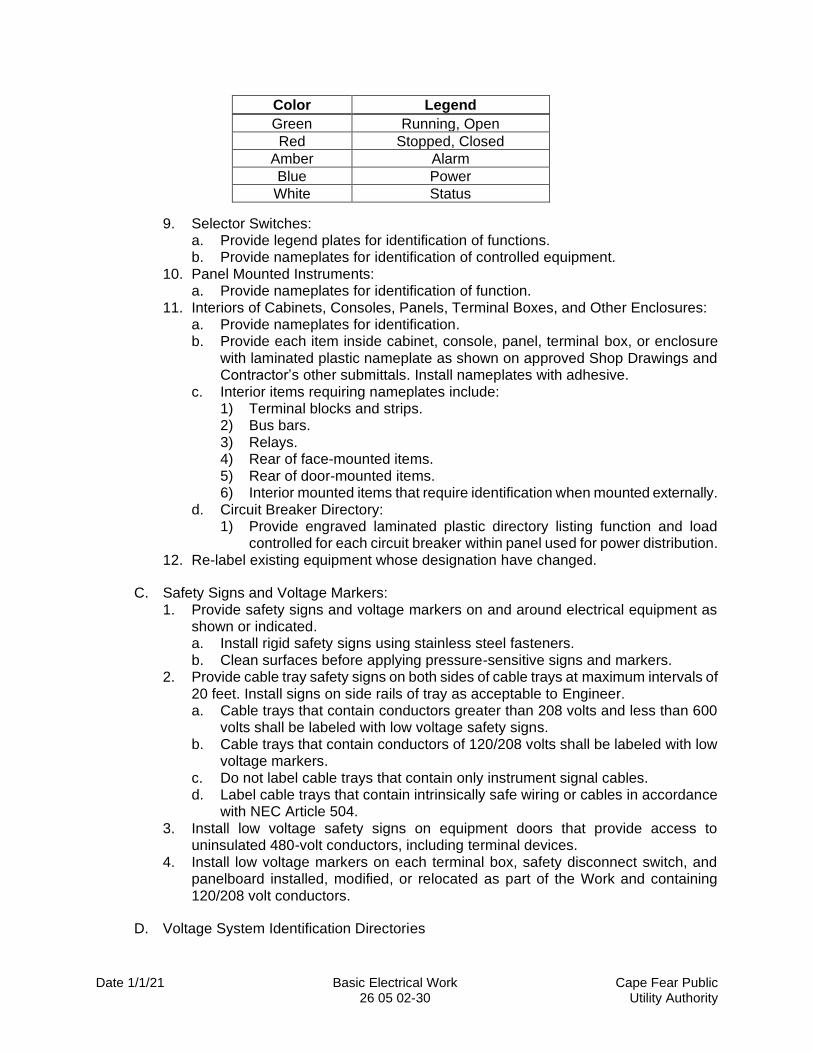
8. Pilot Lights: a. Provide legend plates for identification of functions. b. Provide nameplates for identification of controlled equipment. c. Shall have lens colors as shown or indicated. Where no color is indicated,
provide the following lens colors:
Date 1/1/21 Basic Electrical Work Cape Fear Public 26 05 02-30 Utility Authority
Color Legend
Green Running, Open
Red Stopped, Closed
Amber Alarm
Blue Power
White Status
9. Selector Switches: a. Provide legend plates for identification of functions. b. Provide nameplates for identification of controlled equipment.
10. Panel Mounted Instruments: a. Provide nameplates for identification of function.
11. Interiors of Cabinets, Consoles, Panels, Terminal Boxes, and Other Enclosures: a. Provide nameplates for identification. b. Provide each item inside cabinet, console, panel, terminal box, or enclosure
with laminated plastic nameplate as shown on approved Shop Drawings and Contractor’s other submittals. Install nameplates with adhesive.
c. Interior items requiring nameplates include: 1) Terminal blocks and strips. 2) Bus bars. 3) Relays. 4) Rear of face-mounted items. 5) Rear of door-mounted items. 6) Interior mounted items that require identification when mounted externally.
d. Circuit Breaker Directory: 1) Provide engraved laminated plastic directory listing function and load
controlled for each circuit breaker within panel used for power distribution. 12. Re-label existing equipment whose designation have changed.
C. Safety Signs and Voltage Markers: 1. Provide safety signs and voltage markers on and around electrical equipment as
shown or indicated. a. Install rigid safety signs using stainless steel fasteners. b. Clean surfaces before applying pressure-sensitive signs and markers.
2. Provide cable tray safety signs on both sides of cable trays at maximum intervals of 20 feet. Install signs on side rails of tray as acceptable to Engineer. a. Cable trays that contain conductors greater than 208 volts and less than 600
volts shall be labeled with low voltage safety signs. b. Cable trays that contain conductors of 120/208 volts shall be labeled with low
voltage markers. c. Do not label cable trays that contain only instrument signal cables. d. Label cable trays that contain intrinsically safe wiring or cables in accordance
with NEC Article 504. 3. Install low voltage safety signs on equipment doors that provide access to
uninsulated 480-volt conductors, including terminal devices. 4. Install low voltage markers on each terminal box, safety disconnect switch, and
panelboard installed, modified, or relocated as part of the Work and containing 120/208 volt conductors.
D. Voltage System Identification Directories
Date 1/1/21 Basic Electrical Work Cape Fear Public 26 05 02-31 Utility Authority
1. Provide voltage system identification directories as required by NEC Article 210 and NEC Article 215.
2. For panelboards, switchboards, motor control centers, and other branch circuit or feeder distribution equipment that are not located in electrical rooms, provide voltage system identification directory mounted on equipment. a. Directories shall be affixed using epoxy glue. Screws or bolts shall not
penetrate equipment enclosures. b. Directories shall be readily visible and not obscure labels and other markings on
equipment.
E. Arc-flash Safety Signs: 1. Provide arc-flash safety signs as required by NEC Article 110. 2. Provide signs for switchboards, panelboards, motor control centers, and industrial
control panels. Provide signs for control panels that contain 480 volt equipment.
F. Wire and Cable Identification: 1. Color-coding of insulated conductors shall comply with This Section, Low Voltage
Electrical Power Conductors and Cables. 2. Use heat-shrinkable wire labels where wire or cable is terminated. Use wrap-around
labels where wire or cable is to be labeled but is not terminated. 3. Do not provide labels for the following:
a. Bare (uninsulated) conductors, unless otherwise shown or indicated as labeled. 4. Provide wire and cable labels for the following:
a. New, rerouted, or revised wire or cable. b. Insulated conductors. c. Wire and cable terminations:
1) Wire labels shall be applied between ½-inch and one inch of completed termination
2) Apply cable labels between ½-inch and one inch of cable breakout into individual conductors.
a) Label individual conductors in a cable after breakout as specified for wires.
d. Wire or cable exiting cabinets, consoles, panels, terminal boxes, and enclosures. 1) Label wires or cables within two inches of entrance to conduit.
e. Wire or cable in junction boxes and pull boxes 1) Label wires or cables within two inches of entrance to conduit.
f. Wire and cable installed in cable tray. 1) Wire and cable shall have labels at maximum intervals of 20 feet.
g. Wire and cable installed without termination in electrical manholes. 1) Wire and cable shall have wrap-around labels applied within one foot of
exiting manhole. 5. Wire and Cable Identification System:
a. Wire and cable labels shall be imprinted with an identifying designator. 1) Wire and cable extending between two devices or items and that does not
undergo a change of function shall be identified by a single unique designator as specified below.
b. Field Wiring: 1) Wire or cable designator shall consist of:
Date 1/1/21 Basic Electrical Work Cape Fear Public 26 05 02-32 Utility Authority
a) Three left-most characters shall consist of the Contract number under which wiring or cable was installed.
b) Fourth character from the left shall be an asterisk (*), a plus sign (+) or a hyphen (-). Do not use other punctuation symbols in a wire designator.
c) Remaining characters shall be alphanumeric and make wire designator unique.
d) Numbering shall reflect actual designations used in the Work and shall be documented in record documents.
c. Cabinet, Console, Panel, and Enclosure Wiring, Internal: 1) New Cabinets, Consoles, Panels, and Enclosures:
a) Wire and cable inside cabinets, consoles, panels, and enclosures shall have designators as specified in Section 40 61 13 – Process Control Systems General Provisions.
6. Modified Cabinets, Consoles, Panels, and Enclosures: a. New or rerouted wire or cable in existing cabinets, consoles, panels, and
enclosures shall be labeled as shown on the Drawings or be assigned a ten-character designator equivalent to field wire designator.
G. Terminal Strip Labeling: 1. Label panel side of terminal to match panel wire number. 2. Label field side of terminal to match field wire number. Terminal number shall not
include the Contract number.
H. Generator System Warning Signs: 1. Provide warning signs for generator systems as required by NEC. 2. Install generator location warning sign on or immediately adjacent to service
equipment, or to “normal” source disconnecting means when generator is located out of sight of service equipment or disconnecting means.
3. Install generator grounding warning sign on enclosure or immediately adjacent to point where generator neutral is connected to grounding electrode system if connection is made remote from generator.
END OF SECTION