SECTION 26 05 19 LOW-VOLTAGE ELECTRICAL POWER CONDUCTORS AND...
144
Texas Eye Care May 5, 2017 6116 S. Staples St. Construction Documents MEP Solutions Engineering Number 17020 26 05 19 - 1 LOW-VOLTAGE ELECTRICAL POWER CONDUCTORS AND CABLES SECTION 26 05 19 LOW-VOLTAGE ELECTRICAL POWER CONDUCTORS AND CABLES PART 1 - GENERAL 1.1 RELATED DOCUMENTS A. Drawings and general provisions of the Contract, including General and Supplementary Conditions and Division 01 Specification Sections, apply to this Section. 1.2 SUMMARY A. This Section includes the following: 1. Building wires and cables rated 600 V and less. 2. Connectors, splices, and terminations rated 600 V and less. 3. Sleeves and sleeve seals for cables. 1.3 DEFINITIONS A. EPDM: Ethylene-propylene-diene terpolymer rubber. B. NBR: Acrylonitrile-butadiene rubber. 1.4 SUBMITTALS A. Product Data: For each type of product indicated. B. Qualification Data: For testing agency. C. Field quality-control test reports. 1.5 QUALITY ASSURANCE A. Testing Agency Qualifications: An independent agency, with the experience and capability to conduct the testing indicated, that is a member company of the InterNational Electrical Testing Association or is a nationally recognized testing laboratory (NRTL) as defined by OSHA in 29 CFR 1910.7, and that is acceptable to authorities having jurisdiction. 1. Testing Agency's Field Supervisor: Person currently certified by the InterNational Electrical Testing Association or the National Institute for Certification in Engineering Technologies to supervise on-site testing specified in Part 3. B. Electrical Components, Devices, and Accessories: Listed and labeled as defined in NFPA 70, Article 100, by a testing agency acceptable to authorities having jurisdiction, and marked for intended use.
Transcript of SECTION 26 05 19 LOW-VOLTAGE ELECTRICAL POWER CONDUCTORS AND...
Texas Eye Care May 5, 2017 6116 S. Staples St. Construction Documents MEP Solutions Engineering Number 17020 26 05 19 - 1 LOW-VOLTAGE ELECTRICAL POWER CONDUCTORS AND CABLES
SECTION 26 05 19 LOW-VOLTAGE ELECTRICAL POWER CONDUCTORS AND CABLES
PART 1 - GENERAL
1.1 RELATED DOCUMENTS
A. Drawings and general provisions of the Contract, including General and Supplementary Conditions and Division 01 Specification Sections, apply to this Section.
1.2 SUMMARY
A. This Section includes the following:
1. Building wires and cables rated 600 V and less. 2. Connectors, splices, and terminations rated 600 V and less. 3. Sleeves and sleeve seals for cables.
1.3 DEFINITIONS
A. EPDM: Ethylene-propylene-diene terpolymer rubber.
B. NBR: Acrylonitrile-butadiene rubber.
1.4 SUBMITTALS
A. Product Data: For each type of product indicated.
B. Qualification Data: For testing agency.
C. Field quality-control test reports.
1.5 QUALITY ASSURANCE
A. Testing Agency Qualifications: An independent agency, with the experience and capability to conduct the testing indicated, that is a member company of the InterNational Electrical Testing Association or is a nationally recognized testing laboratory (NRTL) as defined by OSHA in 29 CFR 1910.7, and that is acceptable to authorities having jurisdiction.
1. Testing Agency's Field Supervisor: Person currently certified by the InterNational Electrical Testing Association or the National Institute for Certification in Engineering Technologies to supervise on-site testing specified in Part 3.
B. Electrical Components, Devices, and Accessories: Listed and labeled as defined in NFPA 70, Article 100, by a testing agency acceptable to authorities having jurisdiction, and marked for intended use.

Texas Eye Care May 5, 2017 6116 S. Staples St. Construction Documents MEP Solutions Engineering Number 17020 26 05 19 - 2 LOW-VOLTAGE ELECTRICAL POWER CONDUCTORS AND CABLES
C. Comply with NFPA 70.
1.6 COORDINATION
A. Set sleeves in cast-in-place concrete, masonry walls, and other structural components as they are constructed.
PART 2 - PRODUCTS
2.1 CONDUCTORS AND CABLES
A. Available Manufacturers: Subject to compliance with requirements, manufacturers offering products that may be incorporated into the Work include, but are not limited to, the following:
B. Manufacturers: Subject to compliance with requirements, provide products by one of the following:
1. Alcan Products Corporation; Alcan Cable Division. 2. American Insulated Wire Corp.; a Leviton Company. 3. General Cable Corporation. 4. Senator Wire & Cable Company. 5. Southwire Company.
C. Copper Conductors: Comply with NEMA WC 70.
D. Conductor Insulation: Comply with NEMA WC 70 for Types THHN-THWN.
2.2 CONNECTORS AND SPLICES
A. Available Manufacturers: Subject to compliance with requirements, manufacturers offering products that may be incorporated into the Work include, but are not limited to, the following:
1. AFC Cable Systems, Inc. 2. Hubbell Power Systems, Inc. 3. O-Z/Gedney; EGS Electrical Group LLC. 4. 3M; Electrical Products Division. 5. Tyco Electronics Corp.
B. Description: Factory-fabricated connectors and splices of size, ampacity rating, material, type, and class for application and service indicated.
2.3 SLEEVES FOR CABLES
A. Steel Pipe Sleeves: ASTM A 53/A 53M, Type E, Grade B, Schedule 40, galvanized steel, plain ends.
Texas Eye Care May 5, 2017 6116 S. Staples St. Construction Documents MEP Solutions Engineering Number 17020 26 05 19 - 3 LOW-VOLTAGE ELECTRICAL POWER CONDUCTORS AND CABLES
B. Cast-Iron Pipe Sleeves: Cast or fabricated "wall pipe," equivalent to ductile-iron pressure pipe, with plain ends and integral waterstop, unless otherwise indicated.
C. Sleeves for Rectangular Openings: Galvanized sheet steel with minimum 0.052- or 0.138-inch (1.3- or 3.5-mm) thickness as indicated and of length to suit application.
D. Coordinate sleeve selection and application with selection and application of firestopping specified in Division 07 Section "Penetration Firestopping."
2.4 SLEEVE SEALS
A. Available Manufacturers: Subject to compliance with requirements, manufacturers offering products that may be incorporated into the Work include, but are not limited to, the following:
B. Basis-of-Design Product: Subject to compliance with requirements, provide the product indicated on Drawings or a comparable product by one of the following:
1. Advance Products & Systems, Inc. 2. Calpico, Inc. 3. Metraflex Co. 4. Pipeline Seal and Insulator, Inc.
C. Description: Modular sealing device, designed for field assembly, to fill annular space between sleeve and cable.
1. Sealing Elements: EPDM interlocking links shaped to fit surface of cable or conduit. Include type and number required for material and size of raceway or cable.
2. Pressure Plates: Plastic. Include two for each sealing element. 3. Connecting Bolts and Nuts: Carbon steel with corrosion-resistant coating of length
required to secure pressure plates to sealing elements. Include one for each sealing element.
PART 3 - EXECUTION
3.1 CONDUCTOR MATERIAL APPLICATIONS
A. Feeders: Copper. Solid for No. 10 AWG and smaller; stranded for No. 8 AWG and larger.
B. Branch Circuits: Copper. Solid for No. 10 AWG and smaller; stranded for No. 8 AWG and larger.
3.2 CONDUCTOR INSULATION AND MULTICONDUCTOR CABLE APPLICATIONS AND WIRING METHODS
A. Service Entrance: Type THHN-THWN, single conductors in raceway.
B. Exposed Feeders: Type THHN-THWN, single conductors in raceway.

Texas Eye Care May 5, 2017 6116 S. Staples St. Construction Documents MEP Solutions Engineering Number 17020 26 05 19 - 4 LOW-VOLTAGE ELECTRICAL POWER CONDUCTORS AND CABLES
C. Feeders Concealed in Ceilings, Walls, Partitions, and Crawlspaces: Type THHN-THWN, single conductors in raceway.
D. Feeders Concealed in Concrete, below Slabs-on-Grade, and Underground: Type THHN-THWN, single conductors in raceway.
E. Exposed Branch Circuits, Including in Crawlspaces: Type THHN-THWN, single conductors in raceway.
F. Branch Circuits Concealed in Ceilings, Walls, and Partitions: Type THHN-THWN, single conductors in raceway.
G. Branch Circuits Concealed in Concrete, below Slabs-on-Grade, and Underground: Type THHN-THWN, single conductors in raceway.
H. Class 1 Control Circuits: Type THHN-THWN, in raceway.
3.3 INSTALLATION OF CONDUCTORS AND CABLES
A. Conceal cables in finished walls, ceilings, and floors, unless otherwise indicated.
B. Use manufacturer-approved pulling compound or lubricant where necessary; compound used must not deteriorate conductor or insulation. Do not exceed manufacturer's recommended maximum pulling tensions and sidewall pressure values.
C. Use pulling means, including fish tape, cable, rope, and basket-weave wire/cable grips, that will not damage cables or raceway.
D. Install exposed cables parallel and perpendicular to surfaces of exposed structural members, and follow surface contours where possible.
E. Support cables according to Division 26 Section "Hangers and Supports for Electrical Systems."
F. Identify and color-code conductors and cables according to Division 26 Section "Identification for Electrical Systems."
3.4 CONNECTIONS
A. Tighten electrical connectors and terminals according to manufacturer's published torque-tightening values. If manufacturer's torque values are not indicated, use those specified in UL 486A and UL 486B.
B. Make splices and taps that are compatible with conductor material and that possess equivalent or better mechanical strength and insulation ratings than unspliced conductors.
C. Wiring at Outlets: Install conductor at each outlet, with at least 12 inches (300 mm) of slack.
Texas Eye Care May 5, 2017 6116 S. Staples St. Construction Documents MEP Solutions Engineering Number 17020 26 05 19 - 5 LOW-VOLTAGE ELECTRICAL POWER CONDUCTORS AND CABLES
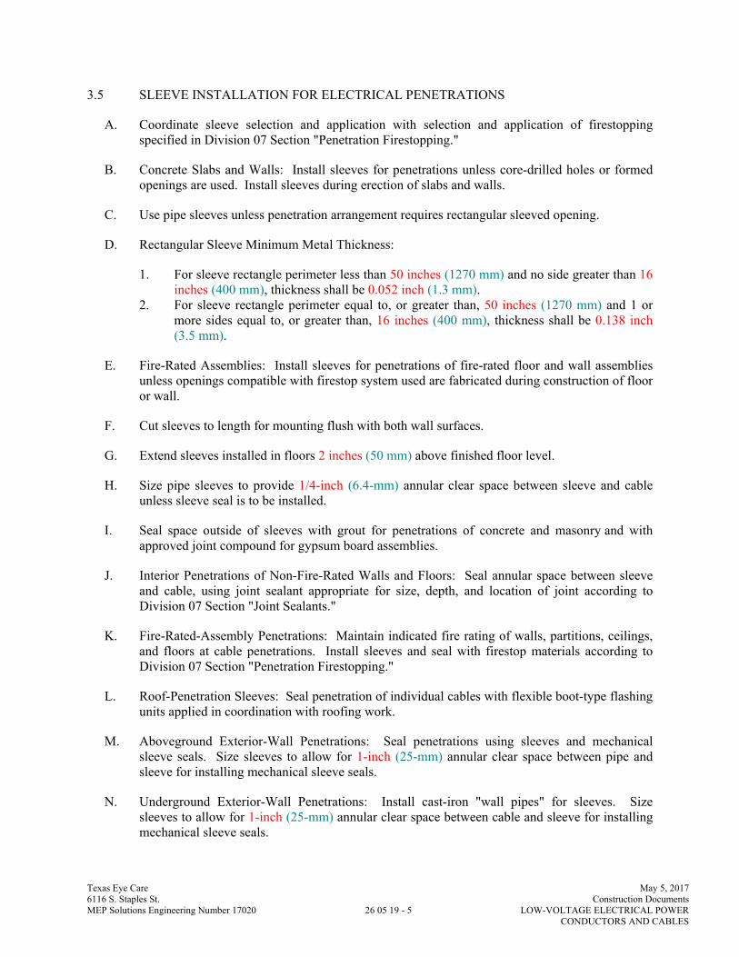
3.5 SLEEVE INSTALLATION FOR ELECTRICAL PENETRATIONS
A. Coordinate sleeve selection and application with selection and application of firestopping specified in Division 07 Section "Penetration Firestopping."
B. Concrete Slabs and Walls: Install sleeves for penetrations unless core-drilled holes or formed openings are used. Install sleeves during erection of slabs and walls.
C. Use pipe sleeves unless penetration arrangement requires rectangular sleeved opening.
D. Rectangular Sleeve Minimum Metal Thickness:
1. For sleeve rectangle perimeter less than 50 inches (1270 mm) and no side greater than 16 inches (400 mm), thickness shall be 0.052 inch (1.3 mm).
2. For sleeve rectangle perimeter equal to, or greater than, 50 inches (1270 mm) and 1 or more sides equal to, or greater than, 16 inches (400 mm), thickness shall be 0.138 inch (3.5 mm).
E. Fire-Rated Assemblies: Install sleeves for penetrations of fire-rated floor and wall assemblies unless openings compatible with firestop system used are fabricated during construction of floor or wall.
F. Cut sleeves to length for mounting flush with both wall surfaces.
G. Extend sleeves installed in floors 2 inches (50 mm) above finished floor level.
H. Size pipe sleeves to provide 1/4-inch (6.4-mm) annular clear space between sleeve and cable unless sleeve seal is to be installed.
I. Seal space outside of sleeves with grout for penetrations of concrete and masonry and with approved joint compound for gypsum board assemblies.
J. Interior Penetrations of Non-Fire-Rated Walls and Floors: Seal annular space between sleeve and cable, using joint sealant appropriate for size, depth, and location of joint according to Division 07 Section "Joint Sealants."
K. Fire-Rated-Assembly Penetrations: Maintain indicated fire rating of walls, partitions, ceilings, and floors at cable penetrations. Install sleeves and seal with firestop materials according to Division 07 Section "Penetration Firestopping."
L. Roof-Penetration Sleeves: Seal penetration of individual cables with flexible boot-type flashing units applied in coordination with roofing work.
M. Aboveground Exterior-Wall Penetrations: Seal penetrations using sleeves and mechanical sleeve seals. Size sleeves to allow for 1-inch (25-mm) annular clear space between pipe and sleeve for installing mechanical sleeve seals.
N. Underground Exterior-Wall Penetrations: Install cast-iron "wall pipes" for sleeves. Size sleeves to allow for 1-inch (25-mm) annular clear space between cable and sleeve for installing mechanical sleeve seals.
Texas Eye Care May 5, 2017 6116 S. Staples St. Construction Documents MEP Solutions Engineering Number 17020 26 05 19 - 6 LOW-VOLTAGE ELECTRICAL POWER CONDUCTORS AND CABLES
3.6 SLEEVE-SEAL INSTALLATION
A. Install to seal underground exterior-wall penetrations.
B. Use type and number of sealing elements recommended by manufacturer for cable material and size. Position cable in center of sleeve. Assemble mechanical sleeve seals and install in annular space between cable and sleeve. Tighten bolts against pressure plates that cause sealing elements to expand and make watertight seal.
3.7 FIRESTOPPING
A. Apply firestopping to electrical penetrations of fire-rated floor and wall assemblies to restore original fire-resistance rating of assembly according to Division 07 Section "Penetration Firestopping."
3.8 FIELD QUALITY CONTROL
A. Perform tests and inspections and prepare test reports.
B. Tests and Inspections:
1. After installing conductors and cables and before electrical circuitry has been energized, test service entrance and feeder conductors, and conductors feeding the following critical equipment and services for compliance with requirements.
C. Test Reports: Prepare a written report to record the following:
1. Test procedures used. 2. Test results that comply with requirements. 3. Test results that do not comply with requirements and corrective action taken to achieve
compliance with requirements.
D. Remove and replace malfunctioning units and retest as specified above.
END OF SECTION 260519
Texas Eye Care May 5, 2017 6116 S. Staples St. Construction Documents MEP Solutions Engineering Number 17020 26 05 26 - 1 GROUNDING AND BONDING FOR ELECTRICAL SYSTEMS
SECTION 26 05 26 GROUNDING AND BONDING FOR ELECTRICAL SYSTEMS
PART 1 - GENERAL
1.1 RELATED DOCUMENTS
A. Drawings and general provisions of the Contract, including General and Supplementary Conditions and Division 01 Specification Sections, apply to this Section.
1.2 SUMMARY
A. Section Includes: Grounding systems and equipment.
1.3 SUBMITTALS
A. Product Data: For each type of product indicated.
B. Informational Submittals: Plans showing dimensioned as-built locations of grounding features specified in "Field Quality Control" Article, including the following: 1. Ground rods. 2. Ground rings. 3. Grounding arrangements and connections for separately derived systems. 4. Grounding for sensitive electronic equipment.
C. Qualification Data: For qualified testing agency and testing agency's field supervisor.
D. Field quality-control reports.
E. Operation and Maintenance Data: For grounding to include in emergency, operation, and maintenance manuals. In addition to items specified in Division 01 Section "Operation and Maintenance Data," include the following:
1.4 QUALITY ASSURANCE
A. Electrical Components, Devices, and Accessories: Listed and labeled as defined in NFPA 70, by a qualified testing agency, and marked for intended location and application.
B. Comply with UL 467 for grounding and bonding materials and equipment.

Texas Eye Care May 5, 2017 6116 S. Staples St. Construction Documents MEP Solutions Engineering Number 17020 26 05 26 - 2 GROUNDING AND BONDING FOR ELECTRICAL SYSTEMS
PART 2 - PRODUCTS
2.1 CONDUCTORS
A. Insulated Conductors: Copper wire or cable insulated for 600 V unless otherwise required by applicable Code or authorities having jurisdiction.
B. Bare Copper Conductors:
1. Solid Conductors: ASTM B 3. 2. Stranded Conductors: ASTM B 8. 3. Tinned Conductors: ASTM B 33. 4. Bonding Cable: 28 kcmil, 14 strands of No. 17 AWG conductor, 1/4 inch (6 mm) in
diameter. 5. Bonding Conductor: No. 4 or No. 6 AWG, stranded conductor. 6. Bonding Jumper: Copper tape, braided conductors terminated with copper ferrules; 1-5/8
inches (41 mm) wide and 1/16 inch (1.6 mm) thick.
C. Bare Grounding Conductor and Conductor Protector for Wood Poles:
1. No. 4 AWG minimum, soft-drawn copper. 2. Conductor Protector: Half-round PVC or wood molding; if wood, use pressure-treated
fir, cypress, or cedar.
D. Grounding Bus: Predrilled rectangular bars of annealed copper, 1/4 by 4 inches (6.3 by 100 mm) in cross section, with 9/32-inch (7.14-mm) holes spaced 1-1/8 inches (28 mm) apart. Stand-off insulators for mounting shall comply with UL 891 for use in switchboards, 600 V. Lexan or PVC, impulse tested at 5000 V.
2.2 CONNECTORS
A. Listed and labeled by an NRTL acceptable to authorities having jurisdiction for applications in which used and for specific types, sizes, and combinations of conductors and other items connected.
B. Bolted Connectors for Conductors and Pipes: Copper or copper alloy, pressure type with at least two bolts.
1. Pipe Connectors: Clamp type, sized for pipe.
C. Welded Connectors: Exothermic-welding kits of types recommended by kit manufacturer for materials being joined and installation conditions.
D. Bus-bar Connectors: Mechanical type, cast silicon bronze, solderless compression-type wire terminals, and long-barrel, two-bolt connection to ground bus bar.

Texas Eye Care May 5, 2017 6116 S. Staples St. Construction Documents MEP Solutions Engineering Number 17020 26 05 26 - 3 GROUNDING AND BONDING FOR ELECTRICAL SYSTEMS
2.3 GROUNDING ELECTRODES
A. Ground Rods: Copper-clad steel, sectional type; 3/4 inch by 10 feet (19 mm by 3 m) in diameter.
PART 3 - EXECUTION
3.1 APPLICATIONS
A. Conductors: Install solid conductor for No. 8 AWG and smaller, and stranded conductors for No. 6 AWG and larger unless otherwise indicated.
B. Underground Grounding Conductors: Install bare tinned-copper conductor, No. 2/0 AWG minimum.
1. Bury at least 24 inches (600 mm) below grade.
C. Isolated Grounding Conductors: Green-colored insulation with continuous yellow stripe. On feeders with isolated ground, identify grounding conductor where visible to normal inspection, with alternating bands of green and yellow tape, with at least three bands of green and two bands of yellow.
D. Grounding Bus: Install in electrical and telephone equipment rooms, in rooms housing service equipment, and elsewhere as indicated.
1. Install bus on insulated spacers 2 inches (50 mm) minimum from wall, 6 inches (150 mm) above finished floor unless otherwise indicated.
2. Where indicated on both sides of doorways, route bus up to top of door frame, across top of doorway, and down to specified height above floor; connect to horizontal bus.
E. Conductor Terminations and Connections:
1. Pipe and Equipment Grounding Conductor Terminations: Bolted connectors. 2. Underground Connections: Welded connectors except at test wells and as otherwise
indicated. 3. Connections to Ground Rods at Test Wells: Bolted connectors. 4. Connections to Structural Steel: Welded connectors.
3.2 GROUNDING UNDERGROUND DISTRIBUTION SYSTEM COMPONENTS
A. Comply with IEEE C2 grounding requirements.
B. Pad-Mounted Transformers and Switches: Install two ground rods and ground ring around the pad. Ground pad-mounted equipment and noncurrent-carrying metal items associated with substations by connecting them to underground cable and grounding electrodes. Install tinned-copper conductor not less than No. 2 AWG for ground ring and for taps to equipment grounding terminals. Bury ground ring not less than 6 inches (150 mm) from the foundation.

Texas Eye Care May 5, 2017 6116 S. Staples St. Construction Documents MEP Solutions Engineering Number 17020 26 05 26 - 4 GROUNDING AND BONDING FOR ELECTRICAL SYSTEMS
3.3 EQUIPMENT GROUNDING
A. Install insulated equipment grounding conductors with all feeders and branch circuits.
B. Install insulated equipment grounding conductors with the following items, in addition to those required by NFPA 70:
1. Feeders and branch circuits. 2. Lighting circuits. 3. Receptacle circuits. 4. Single-phase motor and appliance branch circuits. 5. Three-phase motor and appliance branch circuits. 6. Flexible raceway runs. 7. Armored and metal-clad cable runs. 8. Busway Supply Circuits: Install insulated equipment grounding conductor from
grounding bus in the switchgear, switchboard, or distribution panel to equipment grounding bar terminal on busway.
9. Computer and Rack-Mounted Electronic Equipment Circuits: Install insulated equipment grounding conductor in branch-circuit runs from equipment-area power panels and power-distribution units.
C. Air-Duct Equipment Circuits: Install insulated equipment grounding conductor to duct-mounted electrical devices operating at 120 V and more, including air cleaners, heaters, dampers, humidifiers, and other duct electrical equipment. Bond conductor to each unit and to air duct and connected metallic piping.
D. Water Heater, Heat-Tracing, and Antifrost Heating Cables: Install a separate insulated equipment grounding conductor to each electric water heater and heat-tracing cable. Bond conductor to heater units, piping, connected equipment, and components.
E. Isolated Grounding Receptacle Circuits: Install an insulated equipment grounding conductor connected to the receptacle grounding terminal. Isolate conductor from raceway and from panelboard grounding terminals. Terminate at equipment grounding conductor terminal of the applicable derived system or service unless otherwise indicated.
F. Isolated Equipment Enclosure Circuits: For designated equipment supplied by a branch circuit or feeder, isolate equipment enclosure from supply circuit raceway with a nonmetallic raceway fitting listed for the purpose. Install fitting where raceway enters enclosure, and install a separate insulated equipment grounding conductor. Isolate conductor from raceway and from panelboard grounding terminals. Terminate at equipment grounding conductor terminal of the applicable derived system or service unless otherwise indicated.
G. Signal and Communication Equipment: In addition to grounding and bonding required by NFPA 70, provide a separate grounding system complying with requirements in TIA/ATIS J-STD-607-A.
1. For telephone, alarm, voice and data, and other communication equipment, provide No. 4 AWG minimum insulated grounding conductor in raceway from grounding electrode system to each service location, terminal cabinet, wiring closet, and central equipment location.

Texas Eye Care May 5, 2017 6116 S. Staples St. Construction Documents MEP Solutions Engineering Number 17020 26 05 26 - 5 GROUNDING AND BONDING FOR ELECTRICAL SYSTEMS
2. Service and Central Equipment Locations and Wiring Closets: Terminate grounding conductor on a 1/4-by-4-by-12-inch (6.3-by-100-by-300-mm) grounding bus.
3. Terminal Cabinets: Terminate grounding conductor on cabinet grounding terminal.
H. Metal Poles Supporting Outdoor Lighting Fixtures: Install grounding electrode and a separate insulated equipment grounding conductor in addition to grounding conductor installed with branch-circuit conductors.
3.4 INSTALLATION
A. Grounding Conductors: Route along shortest and straightest paths possible unless otherwise indicated or required by Code. Avoid obstructing access or placing conductors where they may be subjected to strain, impact, or damage.
B. Ground Rods: Drive rods until tops are 2 inches (50 mm) below finished floor or final grade unless otherwise indicated.
1. Interconnect ground rods with grounding electrode conductor below grade and as otherwise indicated. Make connections without exposing steel or damaging coating if any.
2. For grounding electrode system, install at least three rods spaced at least one-rod length from each other and located at least the same distance from other grounding electrodes, and connect to the service grounding electrode conductor.
C. Bonding Straps and Jumpers: Install in locations accessible for inspection and maintenance except where routed through short lengths of conduit.
1. Bonding to Structure: Bond straps directly to basic structure, taking care not to penetrate any adjacent parts.
2. Bonding to Equipment Mounted on Vibration Isolation Hangers and Supports: Install bonding so vibration is not transmitted to rigidly mounted equipment.
3. Use exothermic-welded connectors for outdoor locations; if a disconnect-type connection is required, use a bolted clamp.
D. Grounding and Bonding for Piping:
1. Metal Water Service Pipe: Install insulated copper grounding conductors, in conduit, from building's main service equipment, or grounding bus, to main metal water service entrances to building. Connect grounding conductors to main metal water service pipes; use a bolted clamp connector or bolt a lug-type connector to a pipe flange by using one of the lug bolts of the flange. Where a dielectric main water fitting is installed, connect grounding conductor on street side of fitting. Bond metal grounding conductor conduit or sleeve to conductor at each end.
2. Water Meter Piping: Use braided-type bonding jumpers to electrically bypass water meters. Connect to pipe with a bolted connector.
3. Bond each aboveground portion of gas piping system downstream from equipment shutoff valve.

Texas Eye Care May 5, 2017 6116 S. Staples St. Construction Documents MEP Solutions Engineering Number 17020 26 05 26 - 6 GROUNDING AND BONDING FOR ELECTRICAL SYSTEMS
E. Bonding Interior Metal Ducts: Bond metal air ducts to equipment grounding conductors of associated fans, blowers, electric heaters, and air cleaners. Install tinned bonding jumper to bond across flexible duct connections to achieve continuity.
F. Grounding for Steel Building Structure: Install a driven ground rod at base of each corner column and at intermediate exterior columns at distances not more than 60 feet (18 m) apart.
G. Ufer Ground (Concrete-Encased Grounding Electrode): Fabricate according to NFPA 70; use a minimum of 20 feet (6 m) of bare copper conductor not smaller than No. 4 AWG.
1. If concrete foundation is less than 20 feet (6 m) long, coil excess conductor within base of foundation.
2. Bond grounding conductor to reinforcing steel in at least four locations and to anchor bolts. Extend grounding conductor below grade and connect to building's grounding grid or to grounding electrode external to concrete.
3.5 LABELING
A. Comply with requirements in Division 26 Section "Identification for Electrical Systems" Article for instruction signs. The label or its text shall be green.
B. Install labels at the telecommunications bonding conductor and grounding equalizer and at the grounding electrode conductor where exposed.
1. Label Text: "If this connector or cable is loose or if it must be removed for any reason, notify the facility manager."
3.6 FIELD QUALITY CONTROL
A. Testing Agency: Engage a qualified testing agency to perform tests and inspections.
B. Manufacturer's Field Service: Engage a factory-authorized service representative to inspect, test, and adjust components, assemblies, and equipment installations, including connections.
C. Perform tests and inspections.
D. Tests and Inspections:
1. After installing grounding system but before permanent electrical circuits have been energized, test for compliance with requirements.
2. Inspect physical and mechanical condition. Verify tightness of accessible, bolted, electrical connections with a calibrated torque wrench according to manufacturer's written instructions.
3. Test completed grounding system at each location where a maximum ground-resistance level is specified, at service disconnect enclosure grounding terminal , and at individual ground rods. Make tests at ground rods before any conductors are connected.
a. Measure ground resistance no fewer than two full days after last trace of precipitation and without soil being moistened by any means other than natural

Texas Eye Care May 5, 2017 6116 S. Staples St. Construction Documents MEP Solutions Engineering Number 17020 26 05 26 - 7 GROUNDING AND BONDING FOR ELECTRICAL SYSTEMS
drainage or seepage and without chemical treatment or other artificial means of reducing natural ground resistance.
b. Perform tests by fall-of-potential method according to IEEE 81.
4. Prepare dimensioned Drawings locating each test well, ground rod and ground-rod assembly, and other grounding electrodes. Identify each by letter in alphabetical order, and key to the record of tests and observations. Include the number of rods driven and their depth at each location, and include observations of weather and other phenomena that may affect test results. Describe measures taken to improve test results.
E. Grounding system will be considered defective if it does not pass tests and inspections.
F. Prepare test and inspection reports.
G. Report measured ground resistances that exceed the following values:
1. Power and Lighting Equipment or System with Capacity of 500 kVA and Less: 10 ohms. 2. Power and Lighting Equipment or System with Capacity of 500 to 1000 kVA: 5 ohms. 3. Power and Lighting Equipment or System with Capacity More Than 1000 kVA: 3 ohms. 4. Power Distribution Units or Panelboards Serving Electronic Equipment: 1 ohm(s). 5. Substations and Pad-Mounted Equipment: 5 ohms. 6. Manhole Grounds: 10 ohms.
H. Excessive Ground Resistance: If resistance to ground exceeds specified values, notify Architect promptly and include recommendations to reduce ground resistance.
END OF SECTION 260526

Texas Eye Care May 5, 2017 6116 S. Staples St. Construction Documents MEP Solutions Engineering Number 17020 26 05 33 - 1 RACEWAYS & BOXES FOR ELECTRICAL SYSTEMS
SECTION 26 05 33 RACEWAYS AND BOXES FOR ELECTRICAL SYSTEMS
PART 1 - GENERAL
1.1 RELATED DOCUMENTS
A. Drawings and general provisions of the Contract, including General and Supplementary Conditions and Division 01 Specification Sections, apply to this Section.
1.2 SUMMARY
A. This Section includes raceways, fittings, boxes, enclosures, and cabinets for electrical wiring.
B. Related Sections include the following:
1. Division 26 Section "Underground Ducts and Raceways for Electrical Systems" for exterior ductbanks, manholes, and underground utility construction.
1.3 DEFINITIONS
A. EMT: Electrical metallic tubing.
B. ENT: Electrical nonmetallic tubing.
C. EPDM: Ethylene-propylene-diene terpolymer rubber.
D. FMC: Flexible metal conduit.
E. IMC: Intermediate metal conduit.
F. LFMC: Liquidtight flexible metal conduit.
G. LFNC: Liquidtight flexible nonmetallic conduit.
H. NBR: Acrylonitrile-butadiene rubber.
I. RNC: Rigid nonmetallic conduit.
1.4 SUBMITTALS
A. Product Data: For surface raceways, wireways and fittings, floor boxes, hinged-cover enclosures, and cabinets.
B. Shop Drawings: For the following raceway components. Include plans, elevations, sections, details, and attachments to other work. 1. For handholes and boxes for underground wiring, including the following:

Texas Eye Care May 5, 2017 6116 S. Staples St. Construction Documents MEP Solutions Engineering Number 17020 26 05 33 - 2 RACEWAYS & BOXES FOR ELECTRICAL SYSTEMS
a. Duct entry provisions, including locations and duct sizes. b. Frame and cover design. c. Grounding details. d. Dimensioned locations of cable rack inserts, and pulling-in and lifting irons. e. Joint details.
C. Coordination Drawings: Conduit routing plans, drawn to scale, on which the following items are shown and coordinated with each other, based on input from installers of the items involved:
1. Structural members in the paths of conduit groups with common supports. 2. HVAC and plumbing items and architectural features in the paths of conduit groups with
common supports.
D. Qualification Data: For professional engineer and testing agency.
E. Source quality-control test reports.
1.5 QUALITY ASSURANCE
A. Electrical Components, Devices, and Accessories: Listed and labeled as defined in NFPA 70, Article 100, by a testing agency acceptable to authorities having jurisdiction, and marked for intended use.
B. Comply with NFPA 70.
PART 2 - PRODUCTS
2.1 METAL CONDUIT AND TUBING
A. Available Manufacturers: Subject to compliance with requirements, manufacturers offering products that may be incorporated into the Work include, but are not limited to, the following:
B. Manufacturers: Subject to compliance with requirements, provide products by one of the following:
1. AFC Cable Systems, Inc. 2. Alflex Inc. 3. Allied Tube & Conduit; a Tyco International Ltd. Co. 4. Anamet Electrical, Inc.; Anaconda Metal Hose. 5. Electri-Flex Co. 6. Manhattan/CDT/Cole-Flex. 7. Maverick Tube Corporation. 8. O-Z Gedney; a unit of General Signal. 9. Wheatland Tube Company.
C. Rigid Steel Conduit: ANSI C80.1.
D. Aluminum Rigid Conduit: ANSI C80.5.
Texas Eye Care May 5, 2017 6116 S. Staples St. Construction Documents MEP Solutions Engineering Number 17020 26 05 33 - 3 RACEWAYS & BOXES FOR ELECTRICAL SYSTEMS
E. IMC: ANSI C80.6.
F. PVC-Coated Steel Conduit: PVC-coated rigid steel conduit.
1. Comply with NEMA RN 1. 2. Coating Thickness: 0.040 inch (1 mm), minimum.
G. EMT: ANSI C80.3.
H. FMC: Zinc-coated steel.
I. LFMC: Flexible steel conduit with PVC jacket.
J. Fittings for Conduit (Including all Types and Flexible and Liquidtight), EMT, and Cable: NEMA FB 1; listed for type and size raceway with which used, and for application and environment in which installed.
1. Conduit Fittings for Hazardous (Classified) Locations: Comply with UL 886. 2. Fittings for EMT: Steel, set-screw or compression type. 3. Coating for Fittings for PVC-Coated Conduit: Minimum thickness, 0.040 inch (1 mm),
with overlapping sleeves protecting threaded joints.
K. Joint Compound for Rigid Steel Conduit or IMC: Listed for use in cable connector assemblies, and compounded for use to lubricate and protect threaded raceway joints from corrosion and enhance their conductivity.
2.2 NONMETALLIC CONDUIT AND TUBING
A. Available Manufacturers: Subject to compliance with requirements, manufacturers offering products that may be incorporated into the Work include, but are not limited to, the following:
1. AFC Cable Systems, Inc. 2. Anamet Electrical, Inc.; Anaconda Metal Hose. 3. Arnco Corporation. 4. CANTEX Inc. 5. CertainTeed Corp.; Pipe & Plastics Group. 6. Condux International, Inc. 7. ElecSYS, Inc. 8. Electri-Flex Co. 9. Lamson & Sessions; Carlon Electrical Products. 10. Manhattan/CDT/Cole-Flex. 11. RACO; a Hubbell Company. 12. Thomas & Betts Corporation.
B. ENT: NEMA TC 13.
C. RNC: NEMA TC 2, Type EPC-40-PVC, unless otherwise indicated.
D. LFNC: UL 1660.
E. Fittings for ENT and RNC: NEMA TC 3; match to conduit or tubing type and material.
Texas Eye Care May 5, 2017 6116 S. Staples St. Construction Documents MEP Solutions Engineering Number 17020 26 05 33 - 4 RACEWAYS & BOXES FOR ELECTRICAL SYSTEMS
F. Fittings for LFNC: UL 514B.
2.3 METAL WIREWAYS
A. Available Manufacturers: Subject to compliance with requirements, manufacturers offering products that may be incorporated into the Work include, but are not limited to, the following:
1. Cooper B-Line, Inc. 2. Hoffman. 3. Square D; Schneider Electric.
B. Description: Sheet metal sized and shaped as indicated, NEMA 250, Type 1, unless otherwise indicated.
C. Fittings and Accessories: Include couplings, offsets, elbows, expansion joints, adapters, hold-down straps, end caps, and other fittings to match and mate with wireways as required for complete system.
D. Wireway Covers: Hinged type.
E. Finish: Manufacturer's standard enamel finish.
2.4 NONMETALLIC WIREWAYS
A. Available Manufacturers: Subject to compliance with requirements, manufacturers offering products that may be incorporated into the Work include, but are not limited to, the following:
1. Hoffman. 2. Lamson & Sessions; Carlon Electrical Products.
B. Description: Fiberglass polyester, extruded and fabricated to size and shape indicated, with no holes or knockouts. Cover is gasketed with oil-resistant gasket material and fastened with captive screws treated for corrosion resistance. Connections are flanged, with stainless-steel screws and oil-resistant gaskets.
C. Fittings and Accessories: Include couplings, offsets, elbows, expansion joints, adapters, hold-down straps, end caps, and other fittings to match and mate with wireways as required for complete system.
2.5 SURFACE RACEWAYS
A. Surface Metal Raceways: Galvanized steel with snap-on covers. Manufacturer's standard enamel finish in color selected by Architect.
1. Available Manufacturers: Subject to compliance with requirements, manufacturers offering products that may be incorporated into the Work include, but are not limited to, the following:
Texas Eye Care May 5, 2017 6116 S. Staples St. Construction Documents MEP Solutions Engineering Number 17020 26 05 33 - 5 RACEWAYS & BOXES FOR ELECTRICAL SYSTEMS
a. Thomas & Betts Corporation. b. Walker Systems, Inc.; Wiremold Company (The). c. Wiremold Company (The); Electrical Sales Division.
B. Surface Nonmetallic Raceways: Two-piece construction, manufactured of rigid PVC with texture and color selected by Architect from manufacturer's standard colors.
1. Available Manufacturers: Subject to compliance with requirements, manufacturers offering products that may be incorporated into the Work include, but are not limited to, the following:
2. Manufacturers: Subject to compliance with requirements, provide products by one of the following:
a. Butler Manufacturing Company; Walker Division. b. Enduro Systems, Inc.; Composite Products Division. c. Hubbell Incorporated; Wiring Device-Kellems Division. d. Lamson & Sessions; Carlon Electrical Products. e. Panduit Corp. f. Walker Systems, Inc.; Wiremold Company (The). g. Wiremold Company (The); Electrical Sales Division.
2.6 BOXES, ENCLOSURES, AND CABINETS
A. Manufacturers: Subject to compliance with requirements, provide products by one of the following:
1. Cooper Crouse-Hinds; Div. of Cooper Industries, Inc. 2. EGS/Appleton Electric. 3. Erickson Electrical Equipment Company. 4. Hoffman. 5. Hubbell Incorporated; Killark Electric Manufacturing Co. Division. 6. O-Z/Gedney; a unit of General Signal. 7. RACO; a Hubbell Company. 8. Robroy Industries, Inc.; Enclosure Division. 9. Scott Fetzer Co.; Adalet Division. 10. Spring City Electrical Manufacturing Company. 11. Thomas & Betts Corporation. 12. Walker Systems, Inc.; Wiremold Company (The). 13. Woodhead, Daniel Company; Woodhead Industries, Inc. Subsidiary.
B. Sheet Metal Outlet and Device Boxes: NEMA OS 1.
C. Nonmetallic Outlet and Device Boxes: NEMA OS 2.
D. Metal Floor Boxes: Cast metal, fully adjustable, rectangular.
E. Nonmetallic Floor Boxes: Nonadjustable, round.
F. Cast-Metal Access, Pull, and Junction Boxes: NEMA FB 1, galvanized, cast iron with gasketed cover.

Texas Eye Care May 5, 2017 6116 S. Staples St. Construction Documents MEP Solutions Engineering Number 17020 26 05 33 - 6 RACEWAYS & BOXES FOR ELECTRICAL SYSTEMS
G. Hinged-Cover Enclosures: NEMA 250, Type 1, with continuous-hinge cover with flush latch, unless otherwise indicated.
1. Metal Enclosures: Steel, finished inside and out with manufacturer's standard enamel. 2. Nonmetallic Enclosures: Plastic.
H. Cabinets:
1. NEMA 250, Type 1, galvanized-steel box with removable interior panel and removable front, finished inside and out with manufacturer's standard enamel.
2. Hinged door in front cover with flush latch and concealed hinge. 3. Key latch to match panelboards. 4. Metal barriers to separate wiring of different systems and voltage. 5. Accessory feet where required for freestanding equipment.
2.7 HANDHOLES AND BOXES FOR EXTERIOR UNDERGROUND WIRING
A. Description: Comply with SCTE 77.
1. Color of Frame and Cover: Gray. 2. Configuration: Units shall be designed for flush burial and have closed bottom, unless
otherwise indicated. 3. Cover: Weatherproof, secured by tamper-resistant locking devices and having structural
load rating consistent with enclosure. 4. Cover Finish: Nonskid finish shall have a minimum coefficient of friction of 0.50. 5. Cover Legend: Molded lettering, as indicated for each service. 6. Conduit Entrance Provisions: Conduit-terminating fittings shall mate with entering ducts
for secure, fixed installation in enclosure wall. 7. Handholes 12 inches wide by 24 inches long (300 mm wide by 600 mm long) and larger
shall have inserts for cable racks and pulling-in irons installed before concrete is poured.
B. Polymer-Concrete Handholes and Boxes with Polymer-Concrete Cover: Molded of sand and aggregate, bound together with polymer resin, and reinforced with steel or fiberglass or a combination of the two.
1. Available Manufacturers: Subject to compliance with requirements, manufacturers offering products that may be incorporated into the Work include, but are not limited to, the following:
2. Basis-of-Design Product: Subject to compliance with requirements, provide the product indicated on Drawings or a comparable product by one of the following:
a. Armorcast Products Company. b. Carson Industries LLC. c. CDR Systems Corporation. d. NewBasis.
Texas Eye Care May 5, 2017 6116 S. Staples St. Construction Documents MEP Solutions Engineering Number 17020 26 05 33 - 7 RACEWAYS & BOXES FOR ELECTRICAL SYSTEMS
2.8 SLEEVES FOR RACEWAYS
A. Steel Pipe Sleeves: ASTM A 53/A 53M, Type E, Grade B, Schedule 40, galvanized steel, plain ends.
B. Cast-Iron Pipe Sleeves: Cast or fabricated "wall pipe," equivalent to ductile-iron pressure pipe, with plain ends and integral waterstop, unless otherwise indicated.
C. Sleeves for Rectangular Openings: Galvanized sheet steel with minimum 0.052- or 0.138-inch (1.3- or 3.5-mm) thickness as indicated and of length to suit application.
D. Coordinate sleeve selection and application with selection and application of firestopping specified in Division 07 Section "Penetration Firestopping."
2.9 SLEEVE SEALS
A. Available Manufacturers: Subject to compliance with requirements, manufacturers offering products that may be incorporated into the Work include, but are not limited to, the following:
B. Basis-of-Design Product: Subject to compliance with requirements, provide the product indicated on Drawings or a comparable product by one of the following:
1. Advance Products & Systems, Inc. 2. Calpico, Inc. 3. Metraflex Co. 4. Pipeline Seal and Insulator, Inc.
C. Description: Modular sealing device, designed for field assembly, to fill annular space between sleeve and cable.
1. Sealing Elements: EPDM interlocking links shaped to fit surface of cable or conduit. Include type and number required for material and size of raceway or cable.
2. Pressure Plates: Carbon steel. Include two for each sealing element. 3. Connecting Bolts and Nuts: Carbon steel with corrosion-resistant coating of length
required to secure pressure plates to sealing elements. Include one for each sealing element.
2.10 SOURCE QUALITY CONTROL FOR UNDERGROUND ENCLOSURES
A. Handhole and Pull-Box Prototype Test: Test prototypes of handholes and boxes for compliance with SCTE 77. Strength tests shall be for specified tier ratings of products supplied.
1. Tests of materials shall be performed by a independent testing agency. 2. Strength tests of complete boxes and covers shall be by either an independent testing
agency or manufacturer. A qualified registered professional engineer shall certify tests by manufacturer.
3. Testing machine pressure gages shall have current calibration certification complying with ISO 9000 and ISO 10012, and traceable to NIST standards.
Texas Eye Care May 5, 2017 6116 S. Staples St. Construction Documents MEP Solutions Engineering Number 17020 26 05 33 - 8 RACEWAYS & BOXES FOR ELECTRICAL SYSTEMS
PART 3 - EXECUTION
3.1 RACEWAY APPLICATION
A. Outdoors: Apply raceway products as specified below, unless otherwise indicated:
1. Exposed Conduit: Rigid steel conduit . 2. Concealed Conduit, Aboveground: Rigid steel conduit. 3. Underground Conduit: RNC, Type EPC-40-PVC, direct buried. 4. Connection to Vibrating Equipment (Including Transformers and Hydraulic, Pneumatic,
Electric Solenoid, or Motor-Driven Equipment): LFNC. 5. Boxes and Enclosures, Aboveground: NEMA 250, Type 3R. 6. Application of Handholes and Boxes for Underground Wiring:
a. Handholes and Pull Boxes in Driveway, Parking Lot, and Off-Roadway Locations, Subject to Occasional, Nondeliberate Loading by Heavy Vehicles: Polymer concrete, SCTE 77, Tier 15 structural load rating.
b. Handholes and Pull Boxes in Sidewalk and Similar Applications with a Safety Factor for Nondeliberate Loading by Vehicles: Polymer-concrete units, SCTE 77, Tier 8 structural load rating.
c. Handholes and Pull Boxes Subject to Light-Duty Pedestrian Traffic Only: Fiberglass-reinforced polyester resin, structurally tested according to SCTE 77 with 3000-lbf (13 345-N) vertical loading.
B. Comply with the following indoor applications, unless otherwise indicated:
1. Exposed, Not Subject to Physical Damage: EMT. 2. Exposed, Not Subject to Severe Physical Damage: EMT. 3. Exposed and Subject to Severe Physical Damage: Rigid steel conduit. Includes
raceways in the following locations:
a. Loading dock. b. Corridors used for traffic of mechanized carts, forklifts, and pallet-handling units. c. Mechanical rooms.
4. Concealed in Ceilings and Interior Walls and Partitions: EMT. 5. Connection to Vibrating Equipment (Including Transformers and Hydraulic, Pneumatic,
Electric Solenoid, or Motor-Driven Equipment): FMC, except use LFMC in damp or wet locations.
6. Damp or Wet Locations: Rigid steel conduit. 7. Raceways for Optical Fiber or Communications Cable in Spaces Used for Environmental
Air: EMT. 8. Raceways for Optical Fiber or Communications Cable Risers in Vertical Shafts: EMT. 9. Raceways for Concealed General Purpose Distribution of Optical Fiber or
Communications Cable: EMT. 10. Boxes and Enclosures: NEMA 250, Type 1, except use NEMA 250, Type 4, stainless
steel in damp or wet locations.
C. Minimum Raceway Size: 1/2-inch (16-mm) trade size.
Texas Eye Care May 5, 2017 6116 S. Staples St. Construction Documents MEP Solutions Engineering Number 17020 26 05 33 - 9 RACEWAYS & BOXES FOR ELECTRICAL SYSTEMS
D. Raceway Fittings: Compatible with raceways and suitable for use and location.
1. Rigid and Intermediate Steel Conduit: Use threaded rigid steel conduit fittings, unless otherwise indicated.
2. PVC Externally Coated, Rigid Steel Conduits: Use only fittings listed for use with that material. Patch and seal all joints, nicks, and scrapes in PVC coating after installing conduits and fittings. Use sealant recommended by fitting manufacturer.
E. Install nonferrous conduit or tubing for circuits operating above 60 Hz. Where aluminum raceways are installed for such circuits and pass through concrete, install in nonmetallic sleeve.
F. Do not install aluminum conduits in contact with concrete.
3.2 INSTALLATION
A. Comply with NECA 1 for installation requirements applicable to products specified in Part 2 except where requirements on Drawings or in this Article are stricter.
B. Keep raceways at least 6 inches (150 mm) away from parallel runs of flues and steam or hot-water pipes. Install horizontal raceway runs above water and steam piping.
C. Complete raceway installation before starting conductor installation.
D. Support raceways as specified in Division 26 Section "Hangers and Supports for Electrical Systems."
E. Arrange stub-ups so curved portions of bends are not visible above the finished slab.
F. Install no more than the equivalent of three 90-degree bends in any conduit run except for communications conduits, for which fewer bends are allowed.
G. Conceal conduit and EMT within finished walls, ceilings, and floors, unless otherwise indicated.
H. Raceways Embedded in Slabs:
1. Run conduit larger than 1-inch (27-mm) trade size, parallel or at right angles to main reinforcement. Where at right angles to reinforcement, place conduit close to slab support.
2. Arrange raceways to cross building expansion joints at right angles with expansion fittings.
3. Change from ENT to RNC, Type EPC-40-PVC, rigid steel conduit, or IMC before rising above the floor.
I. Threaded Conduit Joints, Exposed to Wet, Damp, Corrosive, or Outdoor Conditions: Apply listed compound to threads of raceway and fittings before making up joints. Follow compound manufacturer's written instructions.
J. Raceway Terminations at Locations Subject to Moisture or Vibration: Use insulating bushings to protect conductors, including conductors smaller than No. 4 AWG.
Texas Eye Care May 5, 2017 6116 S. Staples St. Construction Documents MEP Solutions Engineering Number 17020 26 05 33 - 10 RACEWAYS & BOXES FOR ELECTRICAL SYSTEMS
K. Install pull wires in empty raceways. Use polypropylene or monofilament plastic line with not less than 200-lb (90-kg) tensile strength. Leave at least 12 inches (300 mm) of slack at each end of pull wire.
L. Raceways for Optical Fiber and Communications Cable: Install raceways, metallic and nonmetallic, rigid and flexible, as follows:
1. 1-Inch (25-mm) Trade Size and Smaller: Install raceways in maximum lengths of 50 feet (15 m).
2. 1-Inch (25-mm) Trade Size and Larger: Install raceways in maximum lengths of 75 feet (23 m).
3. Install with a maximum of two 90-degree bends or equivalent for each length of raceway unless Drawings show stricter requirements. Separate lengths with pull or junction boxes or terminations at distribution frames or cabinets where necessary to comply with these requirements.
M. Install raceway sealing fittings at suitable, approved, and accessible locations and fill them with listed sealing compound. For concealed raceways, install each fitting in a flush steel box with a blank cover plate having a finish similar to that of adjacent plates or surfaces. Install raceway sealing fittings at the following points:
1. Where conduits pass from warm to cold locations, such as boundaries of refrigerated spaces.
2. Where otherwise required by NFPA 70.
N. Expansion-Joint Fittings for RNC: Install in each run of aboveground conduit that is located where environmental temperature change may exceed 30 deg F (17 deg C), and that has straight-run length that exceeds 25 feet (7.6 m).
1. Install expansion-joint fittings for each of the following locations, and provide type and quantity of fittings that accommodate temperature change listed for location:
a. Outdoor Locations Not Exposed to Direct Sunlight: 125 deg F (70 deg C) temperature change.
b. Outdoor Locations Exposed to Direct Sunlight: 155 deg F (86 deg C) temperature change.
c. Indoor Spaces: Connected with the Outdoors without Physical Separation: 125 deg F (70 deg C) temperature change.
d. Attics: 135 deg F (75 deg C) temperature change.
2. Install fitting(s) that provide expansion and contraction for at least 0.00041 inch per foot of length of straight run per deg F (0.06 mm per meter of length of straight run per deg C) of temperature change.
3. Install each expansion-joint fitting with position, mounting, and piston setting selected according to manufacturer's written instructions for conditions at specific location at the time of installation.
O. Flexible Conduit Connections: Use maximum of 72 inches (1830 mm) of flexible conduit for recessed and semirecessed lighting fixtures, equipment subject to vibration, noise transmission, or movement; and for transformers and motors.

Texas Eye Care May 5, 2017 6116 S. Staples St. Construction Documents MEP Solutions Engineering Number 17020 26 05 33 - 11 RACEWAYS & BOXES FOR ELECTRICAL SYSTEMS
1. Use LFMC in damp or wet locations subject to severe physical damage. 2. Use LFMC or LFNC in damp or wet locations not subject to severe physical damage.
P. Recessed Boxes in Masonry Walls: Saw-cut opening for box in center of cell of masonry block, and install box flush with surface of wall.
Q. Set metal floor boxes level and flush with finished floor surface.
R. Set nonmetallic floor boxes level. Trim after installation to fit flush with finished floor surface.
3.3 INSTALLATION OF UNDERGROUND CONDUIT
A. Direct-Buried Conduit:
1. Excavate trench bottom to provide firm and uniform support for conduit. Prepare trench bottom as specified in Division 31 Section "Earth Moving" for pipe less than 6 inches (150 mm) in nominal diameter.
2. Install backfill as specified in Division 31 Section "Earth Moving." 3. After installing conduit, backfill and compact. Start at tie-in point, and work toward end
of conduit run, leaving conduit at end of run free to move with expansion and contraction as temperature changes during this process. Firmly hand tamp backfill around conduit to provide maximum supporting strength. After placing controlled backfill to within 12 inches (300 mm) of finished grade, make final conduit connection at end of run and complete backfilling with normal compaction as specified in Division 31 Section "Earth Moving."
4. Install manufactured duct elbows for stub-ups at poles and equipment and at building entrances through the floor, unless otherwise indicated. Encase elbows for stub-up ducts throughout the length of the elbow.
5. Install manufactured rigid steel conduit elbows for stub-ups at poles and equipment and at building entrances through the floor.
a. Couple steel conduits to ducts with adapters designed for this purpose, and encase coupling with 3 inches (75 mm) of concrete.
b. For stub-ups at equipment mounted on outdoor concrete bases, extend steel conduit horizontally a minimum of 60 inches (1500 mm) from edge of equipment pad or foundation. Install insulated grounding bushings on terminations at equipment.
6. Warning Planks: Bury warning planks approximately 12 inches (300 mm) above direct-buried conduits, placing them 24 inches (600 mm) o.c. Align planks along the width and along the centerline of conduit.
3.4 INSTALLATION OF UNDERGROUND HANDHOLES AND BOXES
A. Install handholes and boxes level and plumb and with orientation and depth coordinated with connecting conduits to minimize bends and deflections required for proper entrances.
B. Unless otherwise indicated, support units on a level bed of crushed stone or gravel, graded from 1/2-inch (12.5-mm) sieve to No. 4 (4.75-mm) sieve and compacted to same density as adjacent undisturbed earth.

Texas Eye Care May 5, 2017 6116 S. Staples St. Construction Documents MEP Solutions Engineering Number 17020 26 05 33 - 12 RACEWAYS & BOXES FOR ELECTRICAL SYSTEMS
C. Elevation: In paved areas, set so cover surface will be flush with finished grade. Set covers of other enclosures 1 inch (25 mm) above finished grade.
D. Install removable hardware, including pulling eyes, cable stanchions, cable arms, and insulators, as required for installation and support of cables and conductors and as indicated. Select arm lengths to be long enough to provide spare space for future cables, but short enough to preserve adequate working clearances in the enclosure.
E. Field-cut openings for conduits according to enclosure manufacturer's written instructions. Cut wall of enclosure with a tool designed for material to be cut. Size holes for terminating fittings to be used, and seal around penetrations after fittings are installed.
3.5 SLEEVE INSTALLATION FOR ELECTRICAL PENETRATIONS
A. Coordinate sleeve selection and application with selection and application of firestopping specified in Division 07 Section "Penetration Firestopping."
B. Concrete Slabs and Walls: Install sleeves for penetrations unless core-drilled holes or formed openings are used. Install sleeves during erection of slabs and walls.
C. Use pipe sleeves unless penetration arrangement requires rectangular sleeved opening.
D. Rectangular Sleeve Minimum Metal Thickness:
1. For sleeve cross-section rectangle perimeter less than 50 inches (1270 mm) and no side greater than 16 inches (400 mm), thickness shall be 0.052 inch (1.3 mm).
2. For sleeve cross-section rectangle perimeter equal to, or greater than, 50 inches (1270 mm) and 1 or more sides equal to, or greater than, 16 inches (400 mm), thickness shall be 0.138 inch (3.5 mm).
E. Fire-Rated Assemblies: Install sleeves for penetrations of fire-rated floor and wall assemblies unless openings compatible with firestop system used are fabricated during construction of floor or wall.
F. Cut sleeves to length for mounting flush with both surfaces of walls.
G. Extend sleeves installed in floors 2 inches (50 mm) above finished floor level.
H. Size pipe sleeves to provide 1/4-inch (6.4-mm) annular clear space between sleeve and raceway unless sleeve seal is to be installed.
I. Seal space outside of sleeves with grout for penetrations of concrete and masonry and with approved joint compound for gypsum board assemblies.
J. Interior Penetrations of Non-Fire-Rated Walls and Floors: Seal annular space between sleeve and raceway, using joint sealant appropriate for size, depth, and location of joint. Refer to Division 07 Section "Joint Sealants" for materials and installation.
K. Fire-Rated-Assembly Penetrations: Maintain indicated fire rating of walls, partitions, ceilings, and floors at raceway penetrations. Install sleeves and seal with firestop materials. Comply with Division 07 Section "Penetration Firestopping."

Texas Eye Care May 5, 2017 6116 S. Staples St. Construction Documents MEP Solutions Engineering Number 17020 26 05 33 - 13 RACEWAYS & BOXES FOR ELECTRICAL SYSTEMS
L. Roof-Penetration Sleeves: Seal penetration of individual raceways with flexible, boot-type flashing units applied in coordination with roofing work.
M. Aboveground, Exterior-Wall Penetrations: Seal penetrations using sleeves and mechanical sleeve seals. Select sleeve size to allow for 1-inch (25-mm) annular clear space between pipe and sleeve for installing mechanical sleeve seals.
N. Underground, Exterior-Wall Penetrations: Install cast-iron "wall pipes" for sleeves. Size sleeves to allow for 1-inch (25-mm) annular clear space between raceway and sleeve for installing mechanical sleeve seals.
3.6 SLEEVE-SEAL INSTALLATION
A. Install to seal underground, exterior wall penetrations.
B. Use type and number of sealing elements recommended by manufacturer for raceway material and size. Position raceway in center of sleeve. Assemble mechanical sleeve seals and install in annular space between raceway and sleeve. Tighten bolts against pressure plates that cause sealing elements to expand and make watertight seal.
3.7 FIRESTOPPING
A. Apply firestopping to electrical penetrations of fire-rated floor and wall assemblies to restore original fire-resistance rating of assembly. Firestopping materials and installation requirements are specified in Division 07 Section "Penetration Firestopping."
3.8 PROTECTION
A. Provide final protection and maintain conditions that ensure coatings, finishes, and cabinets are without damage or deterioration at time of Substantial Completion.
1. Repair damage to galvanized finishes with zinc-rich paint recommended by manufacturer.
2. Repair damage to PVC or paint finishes with matching touchup coating recommended by manufacturer.
END OF SECTION 260533
Texas Eye Care May 5, 2017 6116 S. Staples St. Construction Documents MEP Solutions Engineering Number 17020 26 05 44 - 1 SLEEVES AND SLEEVE SEALS FOR ELECTRICAL RACEWAYS AND CABLING
SECTION 26 05 44 SLEEVES AND SLEEVE SEALS FOR ELECTRICAL RACEWAYS AND CABLING
PART 1 - GENERAL
1.1 RELATED DOCUMENTS
A. Drawings and general provisions of the Contract, including General and Supplementary Conditions and Division 01 Specification Sections, apply to this Section.
1.2 SUMMARY
A. Section Includes:
1. Sleeves for raceway and cable penetration of non-fire-rated construction walls and floors. 2. Sleeve-seal systems. 3. Sleeve-seal fittings. 4. Grout. 5. Silicone sealants.
B. Related Requirements:
1. Division 07 Section "Penetration Firestopping" for penetration firestopping installed in fire-resistance-rated walls, horizontal assemblies, and smoke barriers, with and without penetrating items.
1.3 ACTION SUBMITTALS
A. Product Data: For each type of product.
B. LEED Submittals:
1. Product Data for Credit EQ 4.1: For sealants, documentation including printed statement of VOC content.
2. Laboratory Test Reports for Credit EQ 4: For sealants, documentation indicating that products comply with the testing and product requirements of the California Department of Health Services' "Standard Practice for the Testing of Volatile Organic Emissions from Various Sources Using Small-Scale Environmental Chambers."

Texas Eye Care May 5, 2017 6116 S. Staples St. Construction Documents MEP Solutions Engineering Number 17020 26 05 44 - 2 SLEEVES AND SLEEVE SEALS FOR ELECTRICAL RACEWAYS AND CABLING
PART 2 - PRODUCTS
2.1 SLEEVES
A. Wall Sleeves:
1. Steel Pipe Sleeves: ASTM A 53/A 53M, Type E, Grade B, Schedule 40, zinc coated, plain ends.
2. Cast-Iron Pipe Sleeves: Cast or fabricated "wall pipe," equivalent to ductile-iron pressure pipe, with plain ends and integral waterstop unless otherwise indicated.
B. Sleeves for Conduits Penetrating Non-Fire-Rated Gypsum Board Assemblies: Galvanized-steel sheet; 0.0239-inch (0.6-mm) minimum thickness; round tube closed with welded longitudinal joint, with tabs for screw-fastening the sleeve to the board.
C. PVC-Pipe Sleeves: ASTM D 1785, Schedule 40.
D. Sleeves for Rectangular Openings:
1. Material: Galvanized sheet steel. 2. Minimum Metal Thickness:
a. For sleeve cross-section rectangle perimeter less than 50 inches (1270 mm) and with no side larger than 16 inches (400 mm), thickness shall be 0.052 inch (1.3 mm).
b. For sleeve cross-section rectangle perimeter 50 inches (1270 mm) or more and one or more sides larger than 16 inches (400 mm), thickness shall be 0.138 inch (3.5 mm).
2.2 SLEEVE-SEAL SYSTEMS
A. Description: Modular sealing device, designed for field assembly, to fill annular space between sleeve and raceway or cable.
1. Manufacturers: Subject to compliance with requirements, provide products by the following provide products by one of the following available manufacturers offering products that may be incorporated into the Work include, but are not limited to, the following:
a. Advance Products & Systems, Inc. b. CALPICO, Inc. c. Metraflex Company (The). d. Pipeline Seal and Insulator, Inc. e. Proco Products, Inc.

Texas Eye Care May 5, 2017 6116 S. Staples St. Construction Documents MEP Solutions Engineering Number 17020 26 05 44 - 3 SLEEVES AND SLEEVE SEALS FOR ELECTRICAL RACEWAYS AND CABLING
2. Sealing Elements: EPDM rubber interlocking links shaped to fit surface of pipe. Include type and number required for pipe material and size of pipe.
3. Pressure Plates: Carbon steel. 4. Connecting Bolts and Nuts: Carbon steel, with corrosion-resistant coating, of length
required to secure pressure plates to sealing elements.
2.3 SLEEVE-SEAL FITTINGS
A. Description: Manufactured plastic, sleeve-type, waterstop assembly made for embedding in concrete slab or wall. Unit shall have plastic or rubber waterstop collar with center opening to match piping OD.
1. Manufacturers: Subject to compliance with requirements, available manufacturers offering products that may be incorporated into the Work include, but are not limited to, the following:
a. Presealed Systems.
2.4 GROUT
A. Description: Nonshrink; recommended for interior and exterior sealing openings in non-fire-rated walls or floors.
B. Standard: ASTM C 1107/C 1107M, Grade B, post-hardening and volume-adjusting, dry, hydraulic-cement grout.
C. Design Mix: 5000-psi (34.5-MPa), 28-day compressive strength.
D. Packaging: Premixed and factory packaged.
2.5 SILICONE SEALANTS
A. Silicone Sealants: Single-component, silicone-based, neutral-curing elastomeric sealants of grade indicated below.
1. Grade: Pourable (self-leveling) formulation for openings in floors and other horizontal surfaces that are not fire rated.
B. Silicone Foams: Multicomponent, silicone-based liquid elastomers that, when mixed, expand and cure in place to produce a flexible, nonshrinking foam.
Texas Eye Care May 5, 2017 6116 S. Staples St. Construction Documents MEP Solutions Engineering Number 17020 26 05 44 - 4 SLEEVES AND SLEEVE SEALS FOR ELECTRICAL RACEWAYS AND CABLING
PART 3 - EXECUTION
3.1 SLEEVE INSTALLATION FOR NON-FIRE-RATED ELECTRICAL PENETRATIONS
A. Comply with NECA 1.
B. Comply with NEMA VE 2 for cable tray and cable penetrations.
C. Sleeves for Conduits Penetrating Above-Grade Non-Fire-Rated Concrete and Masonry-Unit Floors and Walls:
1. Interior Penetrations of Non-Fire-Rated Walls and Floors:
a. Seal annular space between sleeve and raceway or cable, using joint sealant appropriate for size, depth, and location of joint. Comply with requirements in Division 07 Section "Joint Sealants."
b. Seal space outside of sleeves with mortar or grout. Pack sealing material solidly between sleeve and wall so no voids remain. Tool exposed surfaces smooth; protect material while curing.
2. Use pipe sleeves unless penetration arrangement requires rectangular sleeved opening. 3. Size pipe sleeves to provide 1/4-inch (6.4-mm) annular clear space between sleeve and
raceway or cable unless sleeve seal is to be installed. 4. Install sleeves for wall penetrations unless core-drilled holes or formed openings are
used. Install sleeves during erection of walls. Cut sleeves to length for mounting flush with both surfaces of walls. Deburr after cutting.
5. Install sleeves for floor penetrations. Extend sleeves installed in floors 2 inches (50 mm) above finished floor level. Install sleeves during erection of floors.
D. Sleeves for Conduits Penetrating Non-Fire-Rated Gypsum Board Assemblies:
1. Use circular metal sleeves unless penetration arrangement requires rectangular sleeved opening.
2. Seal space outside of sleeves with approved joint compound for gypsum board assemblies.
E. Roof-Penetration Sleeves: Seal penetration of individual raceways and cables with flexible boot-type flashing units applied in coordination with roofing work.
F. Aboveground, Exterior-Wall Penetrations: Seal penetrations using [steel] [cast-iron] pipe sleeves and mechanical sleeve seals. Select sleeve size to allow for 1-inch (25-mm) annular clear space between pipe and sleeve for installing mechanical sleeve seals.
G. Underground, Exterior-Wall and Floor Penetrations: Install cast-iron pipe sleeves. Size sleeves to allow for 1-inch (25-mm) annular clear space between raceway or cable and sleeve for installing sleeve-seal system.
Texas Eye Care May 5, 2017 6116 S. Staples St. Construction Documents MEP Solutions Engineering Number 17020 26 05 44 - 5 SLEEVES AND SLEEVE SEALS FOR ELECTRICAL RACEWAYS AND CABLING
3.2 SLEEVE-SEAL-SYSTEM INSTALLATION
A. Install sleeve-seal systems in sleeves in exterior concrete walls and slabs-on-grade at raceway entries into building.
B. Install type and number of sealing elements recommended by manufacturer for raceway or cable material and size. Position raceway or cable in center of sleeve. Assemble mechanical sleeve seals and install in annular space between raceway or cable and sleeve. Tighten bolts against pressure plates that cause sealing elements to expand and make watertight seal.
3.3 SLEEVE-SEAL-FITTING INSTALLATION
A. Install sleeve-seal fittings in new walls and slabs as they are constructed.
B. Assemble fitting components of length to be flush with both surfaces of concrete slabs and walls. Position waterstop flange to be centered in concrete slab or wall.
C. Secure nailing flanges to concrete forms.
D. Using grout, seal the space around outside of sleeve-seal fittings.
END OF SECTION 260544
Texas Eye Care May 5, 2017 6116 S. Staples St. Construction Documents MEP Solutions Engineering Number 17020 26 05 53 - 1 IDENTIFICATION FOR ELECTRICAL SYSTEMS
SECTION 26 05 53 IDENTIFICATION FOR ELECTRICAL SYSTEMS
PART 1 - GENERAL
1.1 RELATED DOCUMENTS
A. Drawings and general provisions of the Contract, including General and Supplementary Conditions and Division 01 Specification Sections, apply to this Section.
1.2 SUMMARY
A. Section Includes:
1. Identification for raceways. 2. Identification of power and control cables. 3. Identification for conductors. 4. Underground-line warning tape. 5. Warning labels and signs. 6. Instruction signs. 7. Equipment identification labels. 8. Miscellaneous identification products.
1.3 SUBMITTALS
A. Product Data: For each electrical identification product indicated.
1.4 QUALITY ASSURANCE
A. Comply with ANSI A13.1.
B. Comply with NFPA 70.
C. Comply with 29 CFR 1910.144 and 29 CFR 1910.145.
D. Comply with ANSI Z535.4 for safety signs and labels.
E. Adhesive-attached labeling materials, including label stocks, laminating adhesives, and inks used by label printers, shall comply with UL 969.
1.5 COORDINATION
A. Coordinate identification names, abbreviations, colors, and other features with requirements in other Sections requiring identification applications, Drawings, Shop Drawings, manufacturer's

Texas Eye Care May 5, 2017 6116 S. Staples St. Construction Documents MEP Solutions Engineering Number 17020 26 05 53 - 2 IDENTIFICATION FOR ELECTRICAL SYSTEMS
wiring diagrams, and the Operation and Maintenance Manual; and with those required by codes, standards, and 29 CFR 1910.145. Use consistent designations throughout Project.
B. Coordinate installation of identifying devices with completion of covering and painting of surfaces where devices are to be applied.
C. Coordinate installation of identifying devices with location of access panels and doors.
D. Install identifying devices before installing acoustical ceilings and similar concealment.
PART 2 - PRODUCTS
2.1 POWER RACEWAY IDENTIFICATION MATERIALS
A. Comply with ANSI A13.1 for minimum size of letters for legend and for minimum length of color field for each raceway size.
B. Colors for Raceways Carrying Circuits at 600 V or Less:
1. Black letters on an orange field. 2. Legend: Indicate voltage and system or service type.
C. Colors for Raceways Carrying Circuits at More Than 600 V:
1. Black letters on an orange field. 2. Legend: "DANGER CONCEALED HIGH VOLTAGE WIRING" with 3-inch- (75-mm-
) high letters on 20-inch (500-mm) centers.
D. Self-Adhesive Vinyl Labels for Raceways Carrying Circuits at 600 V or Less: Preprinted, flexible label laminated with a clear, weather- and chemical-resistant coating and matching wraparound adhesive tape for securing ends of legend label.
E. Snap-Around Labels for Raceways Carrying Circuits at 600 V or Less: Slit, pretensioned, flexible, preprinted, color-coded acrylic sleeve, with diameter sized to suit diameter of raceway or cable it identifies and to stay in place by gripping action.
2.2 ARMORED AND METAL-CLAD CABLE IDENTIFICATION MATERIALS
A. Comply with ANSI A13.1 for minimum size of letters for legend and for minimum length of color field for each raceway and cable size.
B. Colors for Raceways Carrying Circuits at 600 V and Less:
1. Black letters on an orange field. 2. Legend: Indicate voltage[ and system or service type].

Texas Eye Care May 5, 2017 6116 S. Staples St. Construction Documents MEP Solutions Engineering Number 17020 26 05 53 - 3 IDENTIFICATION FOR ELECTRICAL SYSTEMS
C. Colors for Raceways Carrying Circuits at More Than 600 V:
1. Black letters on an orange field. 2. Legend: "DANGER CONCEALED HIGH VOLTAGE WIRING" with 3-inch- (75-mm-
) high letters on 20-inch (500-mm) centers.
D. Self-Adhesive Vinyl Labels: Preprinted, flexible label laminated with a clear, weather- and chemical-resistant coating and matching wraparound adhesive tape for securing ends of legend label.
2.3 POWER AND CONTROL CABLE IDENTIFICATION MATERIALS
A. Comply with ANSI A13.1 for minimum size of letters for legend and for minimum length of color field for each raceway and cable size.
B. Self-Adhesive Vinyl Labels: Preprinted, flexible label laminated with a clear, weather- and chemical-resistant coating and matching wraparound adhesive tape for securing ends of legend label.
C. Snap-Around Labels: Slit, pretensioned, flexible, preprinted, color-coded acrylic sleeve, with diameter sized to suit diameter of raceway or cable it identifies and to stay in place by gripping action.
2.4 CONDUCTOR IDENTIFICATION MATERIALS
A. Color-Coding Conductor Tape: Colored, self-adhesive vinyl tape not less than 3 mils (0.08 mm) thick by 1 to 2 inches (25 to 50 mm) wide.
B. Self-Adhesive Vinyl Labels: Preprinted, flexible label laminated with a clear, weather- and chemical-resistant coating and matching wraparound adhesive tape for securing ends of legend label.
C. Snap-Around Labels: Slit, pretensioned, flexible, preprinted, color-coded acrylic sleeve, with diameter sized to suit diameter of raceway or cable it identifies and to stay in place by gripping action.
2.5 FLOOR MARKING TAPE
A. 2-inch- (50-mm-) wide, 5-mil (0.125-mm) pressure-sensitive vinyl tape, with black and white stripes and clear vinyl overlay.
2.6 UNDERGROUND-LINE WARNING TAPE
A. Tape:

Texas Eye Care May 5, 2017 6116 S. Staples St. Construction Documents MEP Solutions Engineering Number 17020 26 05 53 - 4 IDENTIFICATION FOR ELECTRICAL SYSTEMS
1. Recommended by manufacturer for the method of installation and suitable to identify and locate underground electrical and communications utility lines.
2. Printing on tape shall be permanent and shall not be damaged by burial operations. 3. Tape material and ink shall be chemically inert, and not subject to degrading when
exposed to acids, alkalis, and other destructive substances commonly found in soils.
B. Color and Printing:
1. Comply with ANSI Z535.1 through ANSI Z535.5. 2. Inscriptions for Red-Colored Tapes: ELECTRIC LINE, HIGH VOLTAGE,. 3. Inscriptions for Orange-Colored Tapes: TELEPHONE CABLE, CATV CABLE,
COMMUNICATIONS CABLE, OPTICAL FIBER CABLE,.
C. Tag: [Type I] <Insert drawing designation>:
1. Pigmented polyolefin, bright-colored, continuous-printed on one side with the inscription of the utility, compounded for direct-burial service.
2. Thickness: 4 mils (0.1 mm). 3. Weight: 18.5 lb/1000 sq. ft. (9.0 kg/100 sq. m). 4. 3-Inch (75-mm) Tensile According to ASTM D 882: 30 lbf (133.4 N), and 2500 psi
(17.2 MPa).
2.7 WARNING LABELS AND SIGNS
A. Comply with NFPA 70 and 29 CFR 1910.145.
B. Self-Adhesive Warning Labels: Factory-printed, multicolor, pressure-sensitive adhesive labels, configured for display on front cover, door, or other access to equipment unless otherwise indicated.
C. Baked-Enamel Warning Signs:
1. Preprinted aluminum signs, punched or drilled for fasteners, with colors, legend, and size required for application.
2. 1/4-inch (6.4-mm) grommets in corners for mounting. 3. Nominal size, 7 by 10 inches (180 by 250 mm).
D. Metal-Backed, Butyrate Warning Signs:
1. Weather-resistant, nonfading, preprinted, cellulose-acetate butyrate signs with 0.0396-inch (1-mm) galvanized-steel backing; and with colors, legend, and size required for application.
2. 1/4-inch (6.4-mm) grommets in corners for mounting. 3. Nominal size, 10 by 14 inches (250 by 360 mm).
E. Warning label and sign shall include, but are not limited to, the following legends:
Texas Eye Care May 5, 2017 6116 S. Staples St. Construction Documents MEP Solutions Engineering Number 17020 26 05 53 - 5 IDENTIFICATION FOR ELECTRICAL SYSTEMS
1. Multiple Power Source Warning: "DANGER - ELECTRICAL SHOCK HAZARD - EQUIPMENT HAS MULTIPLE POWER SOURCES."
2. Workspace Clearance Warning: "WARNING - OSHA REGULATION - AREA IN FRONT OF ELECTRICAL EQUIPMENT MUST BE KEPT CLEAR FOR 36 INCHES (915 MM)."
2.8 INSTRUCTION SIGNS
A. Engraved, laminated acrylic or melamine plastic, minimum 1/16 inch (1.6 mm) thick for signs up to 20 sq. inches (129 sq. cm) and 1/8 inch (3.2 mm) thick for larger sizes.
1. Engraved legend with black letters on white face. 2. Punched or drilled for mechanical fasteners. 3. Framed with mitered acrylic molding and arranged for attachment at applicable
equipment.
B. Adhesive Film Label: Machine printed, in black, by thermal transfer or equivalent process. Minimum letter height shall be 3/8 inch (10 mm).
C. Adhesive Film Label with Clear Protective Overlay: Machine printed, in black, by thermal transfer or equivalent process. Minimum letter height shall be 3/8 inch (10 mm). Overlay shall provide a weatherproof and UV-resistant seal for label.
2.9 EQUIPMENT IDENTIFICATION LABELS
A. Adhesive Film Label: Machine printed, in black, by thermal transfer or equivalent process. Minimum letter height shall be 3/8 inch (10 mm).
B. Adhesive Film Label with Clear Protective Overlay: Machine printed, in black, by thermal transfer or equivalent process. Minimum letter height shall be 3/8 inch (10 mm). Overlay shall provide a weatherproof and UV-resistant seal for label.
C. Self-Adhesive, Engraved, Laminated Acrylic or Melamine Label: Adhesive backed, with white letters on a dark-gray background. Minimum letter height shall be 3/8 inch (10 mm).
D. Engraved, Laminated Acrylic or Melamine Label: Punched or drilled for screw mounting. White letters on a dark-gray background. Minimum letter height shall be 3/8 inch (10 mm).
2.10 CABLE TIES
A. General-Purpose Cable Ties: Fungus inert, self extinguishing, one piece, self locking, Type 6/6 nylon.
1. Minimum Width: 3/16 inch (5 mm). 2. Tensile Strength at 73 deg F (23 deg C), According to ASTM D 638: 12,000 psi (82.7
MPa).
Texas Eye Care May 5, 2017 6116 S. Staples St. Construction Documents MEP Solutions Engineering Number 17020 26 05 53 - 6 IDENTIFICATION FOR ELECTRICAL SYSTEMS
3. Temperature Range: Minus 40 to plus 185 deg F (Minus 40 to plus 85 deg C). 4. Color: Black except where used for color-coding.
B. UV-Stabilized Cable Ties: Fungus inert, designed for continuous exposure to exterior sunlight, self extinguishing, one piece, self locking, Type 6/6 nylon.
1. Minimum Width: 3/16 inch (5 mm). 2. Tensile Strength at 73 deg F (23 deg C), According to ASTM D 638: 12,000 psi (82.7
MPa). 3. Temperature Range: Minus 40 to plus 185 deg F (Minus 40 to plus 85 deg C). 4. Color: Black.
C. Plenum-Rated Cable Ties: Self extinguishing, UV stabilized, one piece, self locking.
1. Minimum Width: 3/16 inch (5 mm). 2. Tensile Strength at 73 deg F (23 deg C), According to ASTM D 638: 7000 psi (48.2
MPa). 3. UL 94 Flame Rating: 94V-0. 4. Temperature Range: Minus 50 to plus 284 deg F (Minus 46 to plus 140 deg C). 5. Color: Black.
2.11 MISCELLANEOUS IDENTIFICATION PRODUCTS
A. Paint: Comply with requirements in Division 09 painting Sections for paint materials and application requirements. Select paint system applicable for surface material and location (exterior or interior).
B. Fasteners for Labels and Signs: Self-tapping, stainless-steel screws or stainless-steel machine screws with nuts and flat and lock washers.
PART 3 - EXECUTION
3.1 INSTALLATION
A. Verify identity of each item before installing identification products.
B. Location: Install identification materials and devices at locations for most convenient viewing without interference with operation and maintenance of equipment.
C. Apply identification devices to surfaces that require finish after completing finish work.
D. Self-Adhesive Identification Products: Clean surfaces before application, using materials and methods recommended by manufacturer of identification device.
E. Attach signs and plastic labels that are not self-adhesive type with mechanical fasteners appropriate to the location and substrate.

Texas Eye Care May 5, 2017 6116 S. Staples St. Construction Documents MEP Solutions Engineering Number 17020 26 05 53 - 7 IDENTIFICATION FOR ELECTRICAL SYSTEMS
F. Aluminum Wraparound Marker Labels and Metal Tags: Secure tight to surface of conductor or cable at a location with high visibility and accessibility.
G. Cable Ties: For attaching tags. Use general-purpose type, except as listed below:
1. Outdoors: UV-stabilized nylon. 2. In Spaces Handling Environmental Air: Plenum rated.
H. Underground-Line Warning Tape: During backfilling of trenches install continuous underground-line warning tape directly above line at 6 to 8 inches (150 to 200 mm) below finished grade. Use multiple tapes where width of multiple lines installed in a common trench or concrete envelope exceeds 16 inches (400 mm) overall.
I. Painted Identification: Comply with requirements in Division 09 painting Sections for surface preparation and paint application.
3.2 IDENTIFICATION SCHEDULE
A. Concealed Raceways, Duct Banks, More Than 600 V, within Buildings: Tape and stencil 4-inch- (100-mm-) wide black stripes on 10-inch (250-mm) centers over orange background that extends full length of raceway or duct and is 12 inches (300 mm) wide. Stencil legend "DANGER CONCEALED HIGH VOLTAGE WIRING" with 3-inch- (75-mm-) high black letters on 20-inch (500-mm) centers. Stop stripes at legends. Apply to the following finished surfaces:
1. Floor surface directly above conduits running beneath and within 12 inches (300 mm) of a floor that is in contact with earth or is framed above unexcavated space.
2. Wall surfaces directly external to raceways concealed within wall. 3. Accessible surfaces of concrete envelope around raceways in vertical shafts, exposed in
the building, or concealed above suspended ceilings.
B. Accessible Raceways and Metal-Clad Cables, 600 V or Less, for Service, Feeder, and Branch Circuits More Than [30] <Insert number> A, and [120] <Insert number> V to ground: Identify with [self-adhesive vinyl label] [self-adhesive vinyl tape applied in bands]. Install labels at [10-foot (3-m)] [30-foot (10-m)] maximum intervals.
C. Accessible Raceways and Cables within Buildings: Identify the covers of each junction and pull box of the following systems with self-adhesive vinyl labels with the wiring system legend and system voltage. System legends shall be as follows:
1. Emergency Power. 2. Power. 3. UPS.
D. Power-Circuit Conductor Identification, 600 V or Less: For conductors in vaults, pull and junction boxes, manholes, and handholes, use color-coding conductor tape to identify the phase.

Texas Eye Care May 5, 2017 6116 S. Staples St. Construction Documents MEP Solutions Engineering Number 17020 26 05 53 - 8 IDENTIFICATION FOR ELECTRICAL SYSTEMS
1. Color-Coding for Phase and Voltage Level Identification, 600 V or Less: Use colors listed below for ungrounded service feeder and branch-circuit conductors.
a. Color shall be factory applied or field applied for sizes larger than No. 8 AWG, if authorities having jurisdiction permit.
b. Colors for 208/120-V Circuits:
1) Phase A: Black. 2) Phase B: Red. 3) Phase C: Blue.
c. Colors for 480/277-V Circuits:
1) Phase A: Brown. 2) Phase B: Orange. 3) Phase C: Yellow.
d. Field-Applied, Color-Coding Conductor Tape: Apply in half-lapped turns for a minimum distance of 6 inches (150 mm) from terminal points and in boxes where splices or taps are made. Apply last two turns of tape with no tension to prevent possible unwinding. Locate bands to avoid obscuring factory cable markings.
E. Install instructional sign including the color-code for grounded and ungrounded conductors using adhesive-film-type labels.
F. Auxiliary Electrical Systems Conductor Identification: Identify field-installed alarm, control, and signal connections.
1. Identify conductors, cables, and terminals in enclosures and at junctions, terminals, and pull points. Identify by system and circuit designation.
2. Use system of marker tape designations that is uniform and consistent with system used by manufacturer for factory-installed connections.
3. Coordinate identification with Project Drawings, manufacturer's wiring diagrams, and the Operation and Maintenance Manual.
G. Locations of Underground Lines: Identify with underground-line warning tape for power, lighting, communication, and control wiring and optical fiber cable.
1. Limit use of underground-line warning tape to direct-buried cables. 2. Install underground-line warning tape for both direct-buried cables and cables in
raceway.
H. Workspace Indication: Install floor marking tape to show working clearances in the direction of access to live parts. Workspace shall be as required by NFPA 70 and 29 CFR 1926.403 unless otherwise indicated. Do not install at flush-mounted panelboards and similar equipment in finished spaces.
I. Warning Labels for Indoor Cabinets, Boxes, and Enclosures for Power and Lighting: Self-adhesive warning labels.
Texas Eye Care May 5, 2017 6116 S. Staples St. Construction Documents MEP Solutions Engineering Number 17020 26 05 53 - 9 IDENTIFICATION FOR ELECTRICAL SYSTEMS
1. Comply with 29 CFR 1910.145. 2. Identify system voltage with black letters on an orange background. 3. Apply to exterior of door, cover, or other access. 4. For equipment with multiple power or control sources, apply to door or cover of
equipment including, but not limited to, the following:
a. Power transfer switches. b. Controls with external control power connections.
J. Operating Instruction Signs: Install instruction signs to facilitate proper operation and maintenance of electrical systems and items to which they connect. Install instruction signs with approved legend where instructions are needed for system or equipment operation.
K. Emergency Operating Instruction Signs: Install instruction signs with white legend on a red background with minimum 3/8-inch- (10-mm-) high letters for emergency instructions at equipment used for power transfer.
L. Equipment Identification Labels: On each unit of equipment, install unique designation label that is consistent with wiring diagrams, schedules, and the Operation and Maintenance Manual. Apply labels to disconnect switches and protection equipment, central or master units, control panels, control stations, terminal cabinets, and racks of each system. Systems include power, lighting, control, communication, signal, monitoring, and alarm systems unless equipment is provided with its own identification.
1. Labeling Instructions:
a. Indoor Equipment: Self-adhesive, engraved, laminated acrylic or melamine label. Unless otherwise indicated, provide a single line of text with 1/2-inch- (13-mm-) high letters on 1-1/2-inch- (38-mm-) high label; where two lines of text are required, use labels 2 inches (50 mm) high.
b. Outdoor Equipment: Engraved, laminated acrylic or melamine label Stenciled legend 4 inches (100 mm) high.
c. Elevated Components: Increase sizes of labels and letters to those appropriate for viewing from the floor.
d. Unless provided with self-adhesive means of attachment, fasten labels with appropriate mechanical fasteners that do not change the NEMA or NRTL rating of the enclosure.
2. Equipment to Be Labeled:
a. Panelboards: Typewritten directory of circuits in the location provided by panelboard manufacturer. Panelboard identification shall be self-adhesive, engraved, laminated acrylic or melamine label.
b. Enclosures and electrical cabinets. c. Access doors and panels for concealed electrical items. d. Switchgear. e. Switchboards.

Texas Eye Care May 5, 2017 6116 S. Staples St. Construction Documents MEP Solutions Engineering Number 17020 26 05 53 - 10 IDENTIFICATION FOR ELECTRICAL SYSTEMS
f. Transformers: Label that includes tag designation shown on Drawings for the transformer, feeder, and panelboards or equipment supplied by the secondary.
g. Substations. h. Emergency system boxes and enclosures. i. Motor-control centers. j. Enclosed switches. k. Enclosed circuit breakers. l. Enclosed controllers. m. Variable-speed controllers. n. Push-button stations. o. Power transfer equipment. p. Contactors. q. Remote-controlled switches, dimmer modules, and control devices. r. Battery-inverter units. s. Battery racks. t. Power-generating units. u. Monitoring and control equipment. v. UPS equipment.
END OF SECTION 260553
Texas Eye Care May 5, 2017 6116 S. Staples St. Construction Documents MEP Solutions Engineering Number 17020 26 09 23 - 1 LIGHTING CONTROL SYSTEM
SECTION 26 09 23
NETWORK LIGHTING CONTROLS – LUTRON QUANTUM PART 1 GENERAL 1.01 SECTION INCLUDES
A. Digital-network lighting control system and associated components: 1. Power panels. 2. Fluorescent electronic dimming ballasts. 3. LED drivers. 4. Power interfaces. 5. Main units (Lutron Grafik Eye QS). 6. Lighting control modules (Lutron Energi Savr Node). 7. Digital dimming ballast and switching modules (Lutron EcoSystem). 8. Lighting management hubs. 9. Lighting management system computers. 10. Lighting management system software. 11. Control stations. 12. Low-voltage control interfaces. 13. Wired sensors. 14. Wireless sensors. 15. Accessories.
1.02 RELATED REQUIREMENTS A. Section 12 2400 - Window Shades – Lutron Sivoia QS/Sivoia QS Wireless: Motorized
roller window shades, for interface with lighting control system. B. Section <<______>>: Building automation system, for interface with lighting control
system. C. Section 26 0553 - Identification for Electrical Systems: Identification products and
requirements. D. Section 26 2726 - Wiring Devices - Lutron:
1. Finish requirements for wall controls specified in this section. 2. Accessory receptacles and wallplates, to match lighting controls specified in this
section. E. Section 26 5113 - Luminaires, Ballasts, and Drivers - Lutron. F. Section <<______>>: Audio-video system, for interface with lighting control system.
1.03 REFERENCE STANDARDS A. ANSI C82.11 - American National Standard for Lamp Ballasts - High Frequency
Fluorescent Lamp Ballasts - Supplements; 2011. B. ANSI/ESD S20.20 - Protection of Electrical and Electronic Parts, Assemblies and
Equipment (Excluding Electrically Initiated Explosive Devices); 2014. C. ASTM D4674 - Standard Practice for Accelerated Testing for Color Stability of Plastics
Exposed to Indoor Office Environments; 2002a (Reapproved 2010). D. CAL TITLE 24 P6 – California Code of Regulations, Title 24, Part 6 (California Energy
Code); 2013. E. CSA C22.2 No. 223 – Power Supplies with Extra-low-voltage Class 2 Outputs; 2015. F. IEC 60669-2-1 - Switches for Household and Similar Fixed Electrical Installations - Part 2-
1: Particular Requirements - Electronic Switches; 2009. G. IEC 60929 - AC and/or DC-Supplied Electronic Control Gear for Tubular Fluorescent
Lamps - Performance Requirements; 2015.

Texas Eye Care May 5, 2017 6116 S. Staples St. Construction Documents MEP Solutions Engineering Number 17020 26 09 23 - 2 LIGHTING CONTROL SYSTEM
H. IEC 61000-4-2 - Electromagnetic Compatibility (EMC) - Part 4-2: Testing and Measurement Techniques - Electrostatic Discharge Immunity Test; 2008.
I. IEC 61000-4-5 - Electromagnetic Compatibility (EMC) - Part 4-5: Testing and Measurement Techniques - Surge Immunity Test; 2014.
J. IEC 61347-2-3 - Lamp Control Gear - Part 2-3: Particular Requirements for A.C. and/or D.C. Supplied Electronic Control Gear for Fluorescent Lamps; 2011.
K. IEEE 1789 - Recommended Practice for Modulating Current in High-Brightness LEDs for Mitigating Health Risks to Viewers; 2015.
L. IEEE C62.41.2 - Recommended Practice on Characterization of Surges in Low-Voltage (1000 V and less) AC Power Circuits; 2002 (Cor 1, 2012).
M. ISO 9001 - Quality Management Systems-Requirements; 2008. N. NECA 1 - Standard for Good Workmanship in Electrical Construction; 2010. O. NECA 130 - Standard for Installing and Maintaining Wiring Devices; National Electrical
Contractors Association; 2010. P. NEMA 410 - Performance Testing for Lighting Controls and Switching Devices with
Electronic Drivers and Discharge Ballasts; National Electrical Manufacturers Association; 2011.
Q. NEMA WD 1 - General Color Requirements for Wiring Devices; National Electrical Manufacturers Association; 1999 (R 2010).
R. NFPA 70 - National Electrical Code; National Fire Protection Association; Most Recent Edition Adopted by Authority Having Jurisdiction, Including All Applicable Amendments and Supplements.
S. UL 94 - Tests for Flammability of Plastic Materials for Parts in Devices and Appliances; Current Edition, Including All Revisions.
T. UL 489 - Molded-Case Circuit Breakers, Molded-Case Switches and Circuit Breaker Enclosures; Current Edition, Including All Revisions.
U. UL 508 - Industrial Control Equipment; Underwriters Laboratories Inc.; Current Edition, Including All Revisions.
V. UL 508A - Industrial Control Panels; Underwriters Laboratories Inc.; Current Edition, Including All Revisions.
W. UL 924 - Emergency Lighting and Power Equipment; Current Edition, Including All Revisions.
X. UL 935 - Fluorescent-Lamp Ballasts; Current Edition, Including All Revisions. Y. UL 1310 – Class 2 Power Units; Current Edition, Including All Revisions. Z. UL 1472 - Solid-State Dimming Controls; Current Edition, Including All Revisions. AA. UL 1598C - Light-Emitting Diode (LED) Retrofit Luminaire Conversion Kits; Current
Edition, Including All Revisions. BB. UL 2043 - Fire Test for Heat and Visible Smoke Release for Discrete Products and Their
Accessories Installed in Air-Handling Spaces; Current Edition, Including All Revisions. CC. UL 8750 - Light Emitting Diode (LED) Equipment for Use in Lighting Products; Current
Edition, Including All Revisions. 1.04 ADMINISTRATIVE REQUIREMENTS
A. Coordination: 1. Coordinate the placement of sensors and wall controls with millwork, furniture,
equipment, etc. installed under other sections or by others. 2. Coordinate the placement of wall controls with actual installed door swings. 3. Coordinate the placement of daylight sensors with windows, skylights, and luminaires
to achieve optimum operation. Coordinate placement with ductwork, piping, equipment, or other potential obstructions to light level measurement installed under other sections or by others.

Texas Eye Care May 5, 2017 6116 S. Staples St. Construction Documents MEP Solutions Engineering Number 17020 26 09 23 - 3 LIGHTING CONTROL SYSTEM
4. Where motorized window treatments are to be controlled by the lighting control system provided under this section, coordinate the work with other trades to provide compatible products.
5. Coordinate the work to provide luminaires and lamps compatible with the lighting controls to be installed.
6. Notify Architect of any conflicts or deviations from the contract documents to obtain direction prior to proceeding with work.
B. Preinstallation Meeting: Conduct on-site meeting with lighting control system manufacturer prior to commencing work as part of manufacturer's standard startup services. Manufacturer to review with installer: 1. Low voltage wiring requirements. 2. Separation of power and low voltage/data wiring. 3. Wire labeling. 4. Lighting management hub locations and installation. 5. Control locations. 6. Computer jack locations. 7. Load circuit wiring. 8. Network wiring requirements. 9. Connections to other equipment. 10. Installer responsibilities. 11. Power panel locations.
C. Sequencing: 1. Do not install sensors and wall controls until final surface finishes and painting are
complete. 1.05 SUBMITTALS
A. See Section 01 3000 - Administrative Requirements for submittal procedures. B. Product Data: Include ratings, configurations, standard wiring diagrams, dimensions, colors,
service condition requirements, and installed features. 1. Occupancy/Vacancy Sensors: Include detailed basic motion detection coverage range
diagrams. C. Shop Drawings:
1. Provide schematic system riser diagram indicating component interconnections. Include requirements for interface with other systems.
2. Provide detailed sequence of operations describing system functions. D. Samples:
1. Wall Controls: a. Show available color and finish selections. b. Provide one sample(s) for each product<< proposed for substitution
2. Sensors: Provide one; sample(s) for each product proposed for substitution E. Manufacturer's Installation Instructions: Include application conditions and limitations of use
stipulated by product testing agency. Include instructions for storage, handling, protection, examination, preparation, and installation of product.
F. Project Record Documents: Record actual installed locations and settings for lighting control system components.
G. Operation and Maintenance Data: Include detailed information on lighting control system operation, equipment programming and setup, replacement parts, and recommended maintenance procedures and intervals.
H. Warranty: Submit sample of manufacturer's Warranty or Enhanced Warranty as specified in Part 1 under "WARRANTY". Submit documentation of final execution completed in Owner's name and registered with manufacturer.
Texas Eye Care May 5, 2017 6116 S. Staples St. Construction Documents MEP Solutions Engineering Number 17020 26 09 23 - 4 LIGHTING CONTROL SYSTEM
I. Software: one copy of software provided under this section. 1.06 QUALITY ASSURANCE
A. Conform to requirements of NFPA 70. B. Maintain at the project site a copy of each referenced document that prescribes execution
requirements. C. Manufacturer Qualifications:
1. Company with not less than ten years of experience manufacturing lighting control systems of similar complexity to specified system.
2. Registered to ISO 9001, including in-house engineering for product design activities. 3. Qualified to supply specified products and to honor claims against product presented
in accordance with warranty. 1.07 DELIVERY, STORAGE, AND HANDLING
A. Store products in a clean, dry space in original manufacturer's packaging in accordance with manufacturer's written instructions until ready for installation.
1.08 FIELD CONDITIONS A. Maintain field conditions within manufacturer's required service conditions during and after
installation. 1. System Requirements - Lutron, Unless Otherwise Indicated:
a. Ambient Temperature: b. Lighting Control System Components, Except Those Listed Below: Between
32 and 104 degrees F (0 and 40 degrees C). c. Lighting Management System Computer: Between 50 and 90 degrees F (10 and
35 degrees C). d. Fluorescent Electronic Dimming Ballasts: Between 50 and 140 degrees F (10
and 60 degrees C). e. Relative Humidity: Less than 90 percent, non-condensing.
1.09 WARRANTY A. See Section 01 7800 - Closeout Submittals, for additional warranty requirements. B. Manufacturer's Standard Warranty, With Manufacturer Start-Up; Lutron Standard 2-Year
Warranty; Lutron LSC-B2: 1. Manufacturer Lighting Control System Components, Except Lighting Management
System Computer, Ballasts/Drivers and Ballast Modules: a. First Two Years: b. 100 percent replacement parts coverage, 100 percent manufacturer labor
coverage to troubleshoot and diagnose a lighting issue. c. First-available on-site or remote response time. d. Remote diagnostics for applicable systems. e. Telephone Technical Support: Available 24 hours per day, 7 days per week,
excluding manufacturer holidays. 2. Lighting Management System Computer: One year 100 percent parts coverage, one
year 100 percent manufacturer labor coverage. 3. Ballasts/Drivers and Ballast Modules: Five years 100 percent parts coverage, no
manufacturer labor coverage. --CHOOSE ONLY ONE OF THE THREE OPTIONAL ENHANCED WARRANTIES BELOW--
C. Include as part of the base bid; additional costs for manufacturer's Enhanced Warranty with manufacturer Start-up; Silver Enhanced Warranty; Lutron LSC-E8S; coverage to include items listed under manufacturer's standard warranty with manufacturer start-up above, plus the following upgrades: 1. Manufacturer Lighting Control System Components, Except Lighting Management
System Computer, Ballasts/Drivers and Ballast Modules:

Texas Eye Care May 5, 2017 6116 S. Staples St. Construction Documents MEP Solutions Engineering Number 17020 26 09 23 - 5 LIGHTING CONTROL SYSTEM
2. First Two Years: a. As-available Field Service response; no committed response time. b. Additional Coverage for Years 3-5: 50 percent replacement parts coverage, no
manufacturer labor coverage. c. Additional Coverage for Years 6-8: 25 percent replacement parts coverage, no
manufacturer labor coverage. PART 2 PRODUCTS 2.01 MANUFACTURERS
A. Basis of Design Manufacturer: Lutron Electronics Company, Inc; www.lutron.com. B. Other Acceptable Manufacturers:
1. Products by listed manufacturers are subject to compliance with specified requirements<< and ten day prior approval of Architect
C. Substitutions: 1. All proposed substitutions (clearly delineated as such) must be submitted in writing
for approval by Architect a minimum of 10 working days prior to the bid date and must be made available to all bidders. Proposed substitutes must be accompanied by a review of the specification noting compliance on a line-by-line basis.
2. Any proposed substitutions to be reviewed by Architect at Contractor's expense<< at a rate of $200 per hour;
3. By using pre-approved substitutions, Contractor accepts responsibility and associated costs for all required modifications to related equipment and wiring. Provide complete engineered shop drawings (including power wiring) with deviations from the original design highlighted in an alternate color for review and approval by Architect prior to rough-in.
D. Source Limitations: Furnish products produced by a single manufacturer and obtained from a single supplier.
2.02 DIGITAL-NETWORK LIGHTING CONTROL SYSTEM - GENERAL REQUIREMENTS --CHOOSE ONLY ONE OF THE TWO SENSOR LAYOUT AND TUNING PARAGRAPHS BELOW--
A. Provide products listed, classified, and labeled by Underwriter's Laboratories Inc. (UL) as suitable for the purpose indicated.
B. Unless specifically indicated to be excluded, provide all required equipment, conduit, boxes, wiring, connectors, hardware, supports, accessories, software, system programming, etc. as necessary for a complete operating system that provides the control intent indicated.
C. Shade Control Requirements: 1. Capable of operating shades and recalling shade presets via keypad, contact closure
input, infrared receiver, lighting management system software, or other lighting control system interface.
2. Capable of operating any individual, group, or subgroup of shade electronic drive units within system without requiring separate group controllers.
3. Capable of assigning and reassigning individual, groups, and subgroups of shades to any control within system without requiring additional wiring or hardware changes.
4. Capable of controlling shade speed for tracking within plus or minus 0.125 inch (3.17 mm) throughout entire travel.
5. Provide 10 year power failure memory for preset stops, open and close limits, shade grouping and sub grouping and system configuration.
6. Capable of synchronizing multiple shade electronic drive units of the same size to start, stop and move in unison.
7. Capable of stopping shades within accuracy of 0.125 inch (3.17 mm) at any point between open and close limits.

Texas Eye Care May 5, 2017 6116 S. Staples St. Construction Documents MEP Solutions Engineering Number 17020 26 09 23 - 6 LIGHTING CONTROL SYSTEM
8. Capable of storing up to 250 programmable stop points, including open, close, and any other position.
9. Capable of controlling lights and shades from single wall control button. 10. Capable of adjusting shade limits from user interface.
D. Design lighting control equipment for 10 year operational life while operating continually at any temperature in an ambient temperature range of 32 degrees F (0 degrees C) to 104 degrees F (40 degrees C) and 90 percent non-condensing relative humidity.
E. Electrostatic Discharge Tolerance: Design and test equipment to withstand electrostatic discharges without impairment when tested according to IEC 61000-4-2.
F. Dimming and Switching (Relay) Equipment: 1. Designed so that electrolytic capacitors operate at least 36 degrees F (20 degrees C)
below the capacitor's maximum temperature rating when the device is under fully loaded conditions at maximum rated temperature.
2. Inrush Tolerance: a. Utilize load-handling thyristors (SCRs and triacs), field effect transistors
(FETs) and isolated gate bipolar transistors (IGBTs) with maximum current rating at least two times the rated operating current of the dimmer/relay.
b. Capable of withstanding repetitive inrush current of 50 times the operating current without impacting lifetime of the dimmer/relay.
3. Surge Tolerance: a. Panels: Designed and tested to withstand surges of 6,000 V, 3,000 amps according
to IEEE C62.41.2 and IEC 61000-4-5 without impairment to performance. b. Other Power Handling Devices: Designed and tested to withstand surges of
6,000 V, 200 amps according to IEEE C62.41.2 without impairment to performance.
4. Power Failure Recovery: When power is interrupted and subsequently restored, within 3 seconds lights to automatically return to same levels (dimmed setting, full on, or full off) as prior to power interruption.
5. Dimming Requirements: 6. Line Noise Tolerance: Provide real-time cycle-by-cycle compensation for incoming
line voltage variations including changes in RMS voltage (plus or minus 2 percent change in RMS voltage per cycle), frequency shifts (plus or minus 2 Hz change in frequency per second), dynamic harmonics, and line noise. a. Systems not providing integral cycle-by-cycle compensation to include external
power conditioning equipment as part of dimming system. b. Incorporate electronic "soft-start" default at initial turn-on that smoothly ramps
lights up to the appropriate levels within 0.5 seconds. c. Utilize air gap off to disconnect the load from line supply. d. Control all light sources in smooth and continuous manner. Dimmers with
visible steps are not acceptable. e. Load Types: f. Assign a load type to each dimmer that will provide a proper dimming curve for
the specific light source to be controlled. g. Provide capability of being field-configured to have load types assigned per
circuit. h. Minimum and Maximum Light Levels: User adjustable on a circuit-by-circuit
basis. i. Line Voltage Dimmers:
1) Dimmers for Magnetic Low Voltage (MLV) Transformers:

Texas Eye Care May 5, 2017 6116 S. Staples St. Construction Documents MEP Solutions Engineering Number 17020 26 09 23 - 7 LIGHTING CONTROL SYSTEM
(a) Provide circuitry designed to control and provide a symmetrical AC waveform to input of magnetic low voltage transformers per UL 1472.
(b) Dimmers using unipolar load current devices (such as FETs or SCRs) to include DC current protection in the event of a single device failure.
7. Dimmers for Electronic Low Voltage (ELV) Transformers: Operate transformers via reverse phase control. Alternately, forward phase control dimming may be used if dimming equipment manufacturer has recommended specific ELV transformers being provided. a. Dimmers for Neon and Cold Cathode Transformers:
(a) Magnetic Transformers: Listed for use with normal (low) power factor magnetic transformers.
(b) Electronic Transformers: Must be supported by the ballast equipment manufacturer for control of specific ballasts being provided.
b. Low Voltage Dimming Modules: 1) Coordination Between Low Voltage Dimming Module and Line Voltage Relay: Capable
of being electronically linked to a single zone. 2) Single low voltage
dimming module; capable of controlling the following light sources: (a) 0-10V analog voltage signal.
(1) Provide Class 2 isolated 0-10V output signal conforming to IEC 60929.
(2) Sink current according to IEC 60929. (3) Source current.
(b) 10-0V reverse analog voltage signal. (c) DSI digital communication. (d) DALI broadcast communication per IEC 60929:
(1) Logarithmic intensity values complying with IEC 60929. (2) Linear intensity values for use with LED color intensity
control. (e) PWM per IEC 60929.
8. Switching Requirements: a. Rated Life of Relays: Typical of 1,000,000 cycles at fully rated 16 A for all
lighting loads. b. Switch load in a manner that prevents arcing at mechanical contacts when
power is applied to and removed from load circuits. c. Provide output fully rated for continuous duty for inductive, capacitive, and
resistive loads. G. Device Finishes:
1. Wall Controls: <<Match finishes specified for wiring devices in Section 26 2726, 2. Standard Colors: Comply with NEMA WD1 where applicable. 3. Color Variation in Same Product Family: Maximum delta E of 1, CIE L*a*b color
units. 4. Visible Parts: Exhibit ultraviolet color stability when tested with multiple actinic light
sources as defined in ASTM D4674. Provide proof of testing upon request. H. Interface with building automation system<< as specified in Section _____>>; Lutron
System and Network Integration Consultation; LSC-INT-VISIT. I. Interface with Existing Work: <<______>>.

Texas Eye Care May 5, 2017 6116 S. Staples St. Construction Documents MEP Solutions Engineering Number 17020 26 09 23 - 8 LIGHTING CONTROL SYSTEM
2.03 POWER PANELS A. Provide power panels with configurations as indicated on the drawings. B. General Requirements:
1. Listed to UL 508 as industrial control equipment. 2. Comply with UL 508A and IEC 60669-2-1 as applicable. 3. Delivered and installed as a listed factory-assembled panel. 4. Field wiring accessible from front of panel without removing dimmer assemblies or
other components. 5. Passively cooled via free-convection, unaided by fans or other means. 6. Shipped with each dimmer in mechanical bypass position by means of jumper bar
inserted between input and load terminals. Jumpers to carry full rated load current and be reusable at any time. Mechanical bypass device to allow for switching operation of connected load with dimmer removed by means of circuit breaker.
7. Provided with branch circuit protection for each input circuit unless the panel is a dedicated feed-through type panel or otherwise indicated on the drawings.
8. Branch Circuit Breakers: a. Listed to UL 489 as molded case circuit breaker for use on lighting circuits. b. Provided with visual trip indicator. c. Provide circuit breakers with interrupting capacity as required to provide the
short circuit current rating <<indicated, but not less than:; indicated d. <<10,000; rms symmetrical amperes at 120 VAC. e. <<14,000; rms symmetrical amperes at 277 VAC for dimming. f. <<18,000; rms symmetrical amperes at 277 VAC for switching. g. Thermal-magnetic construction for overload, short-circuit, and over-
temperature protection. Use of breakers without thermal protection requires dimmers/relays to have integral thermal protection to prevent failures when overloaded or ambient temperature is above rating of panel.
h. Equipped with provision for tag-out/lock-out devices to secure circuit breakers in off position when servicing loads.
i. Replaceable without moving or replacing dimmer/relay assemblies or other panel components.
j. Listed as switch duty (SWD) so that loads can be switched on and off by breakers.
9. Provide panels with listed short circuit current rating <<not less than the available a. Minimum Short Circuit Current Rating (SCCR): 65,000 A;
10. Panel Processor; Lutron Circuit Selector: 11. Provide the following capabilities:
a. Operate circuit directly from panel processor for system diagnostics and provide feedback of system operation.
b. Electronically assign each circuit to any zone in lighting control system. c. Determine normal/emergency function of panel and set emergency lighting
levels. d. Where indicated on the drawings, panels to provide two control links. Each
circuit to be capable of transferring control based on independent programming between architectural control system and theatrical controls utilizing the USITT DMX-512 1990 or ESTA DMX-512A protocol.
e. React to changes from control within 20 milliseconds. 12. Diagnostics and Service:
a. Replacing dimmer/relay does not require re-programming of system or processor.

Texas Eye Care May 5, 2017 6116 S. Staples St. Construction Documents MEP Solutions Engineering Number 17020 26 09 23 - 9 LIGHTING CONTROL SYSTEM
b. Include diagnostic LEDs for dimmers/relays to verify proper operation and assist in system troubleshooting.
c. Include tiered control scheme for dealing with component failure that minimizes loss of control for occupant.
d. If lighting control system fails, lights to remain at current level. Panel processor provides local control of lights until system is repaired.
e. If panel processor fails, lights to remain at current level. Circuit breakers can be used to turn lights off or to full light output, allowing non-dim control of lights until panel processor is repaired.
f. If dimmer fails, factory-installed mechanical bypass jumpers to allow each dimmer to be mechanically bypassed. Mechanical bypass device to allow for switching operation of connected load with dimmer removed by means of circuit breaker.
C. Product(s): 1. Specification Grade Dimming Panels:
a. Product: Lutron GP Series Dimming Panels. b. Mounting: Surface. c. Dimmers designed and tested specifically to control incandescent/tungsten,
magnetic low voltage, electronic low voltage, neon/cold cathode, fluorescent dimming ballasts, and non-dim loads.
d. Unless otherwise indicated or required, utilize universal 16 A continuous-use listed dimmers.
e. For loads requiring 0-10V, PWM, or DSI control, utilize compatible multiple load type low voltage dimming modules.
f. Limit current rise time to minimum 350 microseconds as measured from 10 to 90 percent of load current waveform and minimum 525 microseconds as measured from 0 to 100 percent of load current waveform at 50 percent rated dimmer capacity at a 90 degree conduction angle. Current rise time to be minimum 400 microseconds as measured from 10 to 90 percent of load current waveform and minimum 600 microseconds as measured from 0 to 100 percent of load current waveform at 100 percent rated dimmer capacity at a 90 degree conduction angle.
g. Load faults only affect the given circuit. 2. Modular Dimming Panels:
a. Product: Lutron LP Series Dimming Panels. b. Provide <<surface-mounted enclosures unless otherwise indicated Unless
otherwise indicated or required, utilize multiple load type 16 A feed continuous-use listed dimming/switching modules.
c. For switching only circuits, utilize relays rated for minimum of 1,000,000 cycles at fully rated current for all lighting loads.
d. For loads requiring 0-10V, PWM, or DSI control, utilize compatible multiple load type low voltage dimming modules.
3. Modular Combination Panels: a. Product: Lutron CCP Series Custom Combination Panels. b. Provide surface-mounted enclosures unless otherwise indicated Unless
otherwise indicated or required, utilize multiple load type 16 A feed continuous-use listed dimming/switching modules.
c. For switching only circuits, utilize relays rated for typical 1,000,000 cycles at fully rated 16 A for all lighting loads.
Texas Eye Care May 5, 2017 6116 S. Staples St. Construction Documents MEP Solutions Engineering Number 17020 26 09 23 - 10 LIGHTING CONTROL SYSTEM
d. For loads requiring 0-10V, PWM, or DSI control, utilize compatible multiple load type low voltage dimming modules.
4. Relay Panels: a. Product: Lutron XP Series Switching Panels. b. Provide <<surface-mounted; enclosures unless otherwise indicated Lutron
Softswitch circuitry prevents arcing at the relay contacts for all three load types, and extends the relay life in excess of one million cycles. Switching high inrush loads can damage relay controls over time. The arcing of these relays, depending on load, typically will limit relay life to 10,000 or 50,000 cycles.
c. Switching Requirements: d. Utilize 20 A continuous-use rated switching modules; able to switch 20 A
receptacles. e. Rated Life of Relay: Typical of 1,000,000 cycles at fully rated 16 A for all
lighting loads. f. Switch load in a manner that prevents arcing at mechanical contacts when
power is applied to and removed from load circuits. g. Provide output fully rated for continuous duty for inductive, capacitive, and
resistive loads. 5. DC Dimming Panels:
a. Product: Lutron DCI Series Dimming Panels. b. Mounting: Surface. c. Meet recommended electrical noise levels of MRI system manufacturers. d. Operate lamps free from audible noise and flicker throughout entire dimming
range. e. In case of control system failure, supervisory circuit to shut down power to
load. f. Automatically detect and compensate for lamp failures to maintain consistent
DC voltage level. 2.04 FLUORESCENT ELECTRONIC DIMMING BALLASTS
A. General Requirements: 1. Designed for 10 year operational life while operating at maximum case temperature
and 90 percent non-condensing relative humidity. 2. Designed and tested to withstand electrostatic discharges without impairment when
tested according to IEC 61000-4-2. 3. Lamp Starting Method: Programmed rapid start. 4. Maximum Inrush Current: 7 amperes for 120V ballasts and 3 amperes for 277V
ballasts. 5. Current Crest Factor (CCF): Less than 1.7. 6. Comply with ANSI C82.11 and list and label as complying with UL 935. 7. Designed to not interfere with infrared devices operating at frequencies between 38
kHz and 42 kHz. 8. Manufactured in a facility that employs ESD reduction practices in compliance with
ANSI/ESD S20.20. 9. Inaudible in a 27 dBA ambient. 10. No visible change in light output with a variation of plus or minus 10 percent line
voltage input. 11. Actively prevent overheating in T5-HO linear fluorescent lamp applications. 12. Ballasts to track evenly across multiple lamp lengths and all light levels. 13. Comply with IEC 61347-2-3 as applicable.
B. 3-Wire Control:

Texas Eye Care May 5, 2017 6116 S. Staples St. Construction Documents MEP Solutions Engineering Number 17020 26 09 23 - 11 LIGHTING CONTROL SYSTEM
1. Provide integral fault protection to prevent ballast failure in the event of a mis-wire. C. Digital Control:
1. Monitor and report lamp and ballast status. 2. Lights automatically return to the setting prior to power interruption. 3. Each ballast responds independently to:
a. Up to 32 occupant sensors. b. Up to 64 personal control inputs. c. Two daylight sensors.
4. Unique internal reference number visibly displayed on ballast cover. 5. Averages two independent daylight harvesting inputs internally. 6. Responds to digital load shed command. (Example: If light output is at 30 percent and
a load shed command of 10 percent is received, the ballast automatically sets the maximum light output at 90 percent and lowers current light output by three percent to 27 percent).
D. Product(s): 1. 3-Wire Control, One Percent Dimming; Lutron Hi-lume:
a. Dimming Range: 100 percent to one percent relative light output for T4 compact and T5-HO lamps.
b. Surge Tolerance: Designed and tested to withstand Category A surges of 6,000 V according to IEEE C62.41.2 without impairment of performance.
c. Total Harmonic Distortion (THD): Less than 10 percent. 2. 3-Wire and Digital Control, One Percent Dimming; Lutron Hi-lume 3D:
a. Dimming Range: 100 percent to less than one percent relative light output for T8, T5 and T5HO, and five percent relative light output for T5 twin-tube lamps.
b. Surge Tolerance: Designed and tested to withstand Category A surges of 6,000 V according to IEEE C62.41.2 without impairment of performance.
c. Total Harmonic Distortion (THD): Less than 10 percent typical (15 percent for select models).
3. 3-Wire and Digital Control, Ten Percent Dimming; Lutron EcoSystem: a. Dimming Range: 100 to ten percent relative light output for T8, T5, T5HO, and
T5 twin-tube, and five percent relative light output for T4 compact lamps. b. Surge Tolerance: Designed and tested to withstand Category A surges of 4,000
V according to IEEE C62.41.2 without impairment of performance. c. Total Harmonic Distortion (THD): Less than 10 percent typical (15 percent for
select models). d. Digital Control: e. Connect without interface (except for T4 compact lamp ballasts) to:
(a) Occupancy sensors. (b) Daylight sensor. (c) Personal control input (keypad or infrared receiver).
f. Provide a 20V DC source to power connected sensors. g. Generate digital communication commands to distribute ballast and sensor data
on the digital bus. 4. Digital Control, One Percent Dimming; Lutron EcoSystem H-Series:
a. Dimming Range: 100 to less than one percent relative light output for T8, and one percent relative light output for T5 and T5HO lamps.
b. Surge Tolerance: Designed and tested to withstand Category A surges of 4,000 V according to IEEE C62.41.2 without impairment of performance.
c. Total Harmonic Distortion (THD): Less than 10 percent typical (15 percent for select models).

Texas Eye Care May 5, 2017 6116 S. Staples St. Construction Documents MEP Solutions Engineering Number 17020 26 09 23 - 12 LIGHTING CONTROL SYSTEM
2.05 LED DRIVERS A. General Requirements:
1. Operate for at least 50,000 hours at maximum case temperature and 90 percent non-condensing relative humidity.
2. Provide thermal fold-back protection by automatically reducing power output (dimming) to protect LED driver and LED light engine/fixture from damage due to over-temperature conditions that approach or exceed the LED driver's maximum operating temperature at calibration point.
3. Provide integral recording of operating hours and maximum operating temperature to aid in troubleshooting and warranty claims.
4. Designed and tested to withstand electrostatic discharges without impairment when tested according to IEC 61000-4-2.
5. Manufactured in a facility that employs ESD reduction practices in compliance with ANSI/ESD S20.20.
6. UL 8750 recognized or listed as applicable. 7. UL Type TL rated where possible to allow for easier fixture evaluation and listing of
different driver series. 8. UL 1598C listed for field replacement as applicable. 9. Designed and tested to withstand Category A surges of 4,000 V according to IEEE
C62.41.2 without impairment of performance. 10. Class A sound rating; Inaudible in a 27 dBA ambient. 11. Demonstrate no visible change in light output with a variation of plus or minus 10
percent change in line-voltage input. 12. LED drivers of the same family/series to track evenly across multiple fixtures at all
light levels. 13. Offer programmable output currents in 10 mA increments within designed driver
operating ranges for custom fixture length and lumen output configurations, while meeting a low-end dimming range of 100 to 1 percent or 100 to 5 percent as applicable.
14. Meet NEMA 410 inrush requirements for mitigating inrush currents with solid state lighting sources.
15. Employ integral fault protection up to 277 V to prevent LED driver damage or failure in the event of incorrect application of line-voltage to communication link inputs.
16. LED driver may be remote located up to 100 feet (30 m) from LED light engine depending on power outputs required and wire gauge utilized by installer.
B. 3-Wire Control: 1. Provide integral fault protection to prevent driver failure in the event of a mis-wire. 2. Operate from input voltage of 120 V through 277 V at 50/60 Hz.
C. Digital Control (when used with compatible Lutron lighting control systems): 1. Employ power failure memory; LED driver to automatically return to the previous
state/light level upon restoration of utility power. 2. Operate from input voltage of 120 V through 277 V at 50/60 Hz. 3. Automatically go to 100 percent light output upon loss of control link voltage and
lock out system commands until digital control link voltage is restored. Manufacturer to offer UL 924 compliance achievable through use of external Lutron Model LUT-ELI-3PSH interface upon request.
4. Each driver responds independently per system maximum: a. Up to 32 occupant sensors. b. Up to 16 daylight sensors.
Texas Eye Care May 5, 2017 6116 S. Staples St. Construction Documents MEP Solutions Engineering Number 17020 26 09 23 - 13 LIGHTING CONTROL SYSTEM
5. Responds to digital load shed command. (Example: If light output is at 30 percent and a load shed command of 10 percent is received, the ballast automatically sets the maximum light output at 90 percent and lowers current light output by three percent to 27 percent).
6. Digital low-voltage control wiring capable of being wired as either Class 1 or Class 2. D. Product(s):
1. Digital Control, 0.1 Percent Dimming with Soft-On and Fade-to-Black Low End Performance; Lutron Hi-lume (L3D0-Series): a. Dimming Range: 100 to 0.1 percent measured output current. b. Features smooth fade-to-on and fade-to-black (Lutron Soft-On, Fade-to-
Black™) low end dimming performance for an incandescent-like dimming experience.
c. Typically dissipates 0.25 W standby power at 120 V and 0.40 W standby power at 277 V.
d. Complies with FCC requirements of CFR, Title 47, Part 15, for commercial applications at 120-277 V and residential applications at 120 V.
e. Total Harmonic Distortion (THD): Less than 20 percent at maximum power; complies with ANSI C82.11.
f. Class 2 output designed to withstand hot swap of LED loads; meets UL 1310 and CSA C22.2 No. 223.
g. Driver outputs to be short circuit protected, open circuit protected, and overload protected.
h. Constant Voltage Drivers: 1) Support for cove and under-cabinet fixtures at 24 V.
(a) Support LED arrays from 25 W to 96 W. (b) Pulse Width Modulation (PWM) dimming frequency meets IEEE
1789. (c) Meets solid state requirements for power factor, transient
protection, standby power consumption, start time, and operating frequency in Energy Star for Luminaires Version 2.0.
(d) UL listed. 2. 3-Wire Control, 0.1 Percent Dimming; Lutron Hi-lume Premier 0.1% Constant
Voltage (L3D0-Series): a. Dimming Range: 100 to 0.1 percent measured output current. b. Typically dissipates 0.2 W standby power at 120 V and 0.3 W standby power at
277 V. c. Complies with FCC requirements of CFR, Title 47, Part 15, for commercial
applications at 120-277 V and residential applications at 120 V. d. Total Harmonic Distortion (THD): Less than 20 percent at maximum power;
complies with ANSI C82.11. e. UL Class 2 output designed to withstand hot swap of LED loads. f. Driver outputs to be short circuit protected, open circuit protected, and overload
protected. g. Constant Voltage Drivers:
1) Support for cove and under-cabinet fixtures at 24 V. (a) Support LED arrays from 25 W to 96 W. (b) Pulse Width Modulation (PWM) dimming frequency meets IEEE
1789.
Texas Eye Care May 5, 2017 6116 S. Staples St. Construction Documents MEP Solutions Engineering Number 17020 26 09 23 - 14 LIGHTING CONTROL SYSTEM
(c) Meets solid state requirements for power factor, transient protection, standby power consumption, and operating frequency in Energy Star for Luminaires Version 2.0.
(d) UL listed. 3. Forward Phase (Neutral Wire Required), One Percent Dimming; Lutron Hi-lume 1%
(LTE-Series): a. Dimming Range: 100 to one percent relative light output. b. Complies with FCC requirements of CFR, Title 47, Part 15, for commercial and
residential applications at 120 V. c. Total Harmonic Distortion (THD): Less than 20 percent at full output for 40 W
loads; complies with ANSI C82.11. d. Constant Current Drivers:
1) Support for downlights and pendant fixtures from 200 mA to 2.1 A to ensure a compatible driver exists. (a) Support LED arrays up to 53 W. (b) Pulse Width Modulation (PWM) or Constant Current Reduction
(CCR) dimming methods available. 2) Support for troffers, linear pendants, and linear recessed fixtures from
200 mA to 2.1 A to ensure a compatible driver exists. (a) Support LED arrays up to 40 W. (b) Pulse Width Modulation (PWM) or Constant Current Reduction
(CCR) dimming methods available. 3) Support for cove and under-cabinet fixtures from 200 mA to 2.1 A to
ensure a compatible driver exists. (a) Support LED arrays up to 40 W. (b) Pulse Width Modulation (PWM) or Constant Current Reduction
(CCR) dimming methods available. (c) UL listed.
e. Constant Voltage Drivers: 1) Support for downlights and pendant fixtures from 10 V to 60 V (in 0.5 V
steps) to ensure a compatible driver exists. (a) Support LED arrays up to 40 W. (b) Pulse Width Modulation (PWM) dimming method.
2) Support for troffers, linear pendants, and linear recessed fixtures from 10 V to 60 V (in 0.5 V steps) to ensure a compatible driver exists. (a) Support LED arrays up to 40 W. (b) Pulse Width Modulation (PWM) dimming method.
3) Support for cove and under-cabinet fixtures from 10 V to 60 V (in 0.5 V steps) to ensure a compatible driver exists. (a) Support LED arrays up to 40 W. (b) Pulse Width Modulation (PWM) dimming method. (c) UL listed.
4. 3-Wire and Digital Control, One Percent Dimming; Lutron Hi-lume 1% (L3D-Series): a. Dimming Range: 100 to one percent relative light output. b. Complies with FCC requirements of CFR, Title 47, Part 15, for commercial
applications at 120 V or 277 V. c. Total Harmonic Distortion (THD): Less than 20 percent at full output for loads
greater than 25 W typical (higher for select models); complies with ANSI C82.11.
Texas Eye Care May 5, 2017 6116 S. Staples St. Construction Documents MEP Solutions Engineering Number 17020 26 09 23 - 15 LIGHTING CONTROL SYSTEM
d. Constant Current Drivers: 1) Support for downlights and pendant fixtures from 200 mA to 2.1 A to
ensure a compatible driver exists. (a) Support LED arrays up to 53 W. (b) Pulse Width Modulation (PWM) or Constant Current Reduction
(CCR) dimming methods available. 2) Support for troffers, linear pendants, and linear recessed fixtures from
200 mA to 2.1 A to ensure a compatible driver exists. (a) Support LED arrays up to 40 W. (b) Pulse Width Modulation (PWM) or Constant Current Reduction
(CCR) dimming methods available. 3) Support for cove and under-cabinet fixtures from 200 mA to 2.1 A to
ensure a compatible driver exists. (a) Support LED arrays up to 40 W. (b) Pulse Width Modulation (PWM) or Constant Current Reduction
(CCR) dimming methods available. (c) UL listed.
e. Constant Voltage Drivers: 1) Support for downlights and pendant fixtures from 10 V to 60 V (in 0.5 V
steps) to ensure a compatible driver exists. (a) Support LED arrays up to 40 W. (b) Pulse Width Modulation (PWM) dimming method.
2) Support for troffers, linear pendants, and linear recessed fixtures from 10 V to 60 V (in 0.5 V steps) to ensure a compatible driver exists. (a) Support LED arrays up to 40 W. (b) Pulse Width Modulation (PWM) dimming method.
3) Support for cove and under-cabinet fixtures from 10 V to 60 V (in 0.5 V steps) to ensure a compatible driver exists. (a) Support LED arrays up to 40 W. (b) Pulse Width Modulation (PWM) dimming method. (c) UL listed.
5. Digital Control, Five Percent Dimming; Lutron 5-Series (LDE5-Series): a. Dimming Range: 100 to five percent measured output current. b. Typically dissipates 0.2 W standby power at 120 V and 0.3 W standby power at
277 V. c. Complies with FCC requirements of CFR, Title 47, Part 15, for commercial
applications at 120-277 V. d. Constant Current Reduction (CCR) dimming method. e. Total Harmonic Distortion (THD): Less than 21 percent at full load; complies
with ANSI C82.11. f. Constant Current Drivers:
1) Lutron K-Case Form Factor: Support for downlights and pendant fixtures in select currents from 350 mA to 1.4 A to ensure a compatible driver exists. (a) Support LED arrays up to 35 W.
2) Lutron M-Case Form Factor: Support for troffers, linear pendants, and linear recessed fixtures from 150 mA to 2.1 A to ensure a compatible driver exists. (a) Support LED arrays up to 75 W.

Texas Eye Care May 5, 2017 6116 S. Staples St. Construction Documents MEP Solutions Engineering Number 17020 26 09 23 - 16 LIGHTING CONTROL SYSTEM
(b) Meets solid state requirements for power factor, transient protection, standby power consumption, start time, and operating frequency in ENERGY STAR for Luminaires Version 2.0.
(c) Models available to meet the DesignLights Consortium (DLC) power line quality requirements.
6. Digital Control, One Percent Dimming with Soft-On and Fade-to-Black Low End Performance; Lutron Hi-lume 1% Soft-on Fade-to-Black (LDE1-Series): a. Dimming Range: 100 to one percent measured output current. b. Features smooth fade-to-on and fade-to-black (Lutron Soft-On, Fade-to-
Black™) low end dimming performance for an incandescent-like dimming experience.
c. Typically dissipates 0.2 W standby power at 120 V and 0.3 W standby power at 277 V.
d. Complies with FCC requirements of CFR, Title 47, Part 15, for commercial applications at 120-277 V.
e. Employs true Constant Current Reduction (CCR) dimming method from 100 to five percent light level and Pulse Width Modulation (PWM) dimming method from five percent to off.
f. Pulse Width Modulation (PWM) frequency of 240 Hz. g. Total Harmonic Distortion (THD): Less than 20 percent at full output for
drivers greater than 25 W; complies with ANSI C82.11. h. UL Class 2 output. i. Driver outputs to be short circuit protected, open circuit protected, and overload
protected. j. Constant Current Drivers:
1) Lutron K-Case Form Factor: Support for fixtures from 220 mA to 1.4 A over multiple operating ranges. (a) Support LED arrays up to 40 W. (b) Meets solid state requirements for power factor, transient
protection, standby power consumption, start time, and operating frequency in ENERGY STAR for Luminaires Version 2.0.
2) Lutron M-Case Form Factor: Support for fixtures from 150 mA to 2.1 A over multiple operating ranges. (a) Support LED arrays up to 75 W. (b) Meets solid state requirements for power factor, transient
protection, standby power consumption, start time, and operating frequency in ENERGY STAR for Luminaires Version 2.0.
(c) Models available to meet the DesignLights Consortium (DLC) power line quality requirements.
2.06 POWER INTERFACES A. Provide power interfaces as indicated or as required to control the loads as indicated. B. General Requirements:
1. Phase independent of control input. 2. Rated for use in air-handling spaces as defined in UL 2043. 3. Utilize air gap off to disconnect the load from line supply. 4. Diagnostics and Service: Replacing power interface does not require re-programming
of system or processor. C. Product(s):
Texas Eye Care May 5, 2017 6116 S. Staples St. Construction Documents MEP Solutions Engineering Number 17020 26 09 23 - 17 LIGHTING CONTROL SYSTEM
1. Phase-Adaptive Power Module; Lutron PHPM-PA: Provides interface for phase control input to provide full 16 A circuit output of forward/reverse phase control for compatible loads.
2. 3-Wire Fluorescent Power Module; Lutron PHPM-3F: Provides interface for phase control input to provide full 16 A circuit output for compatible line-voltage control fluorescent electronic dimming ballasts or LED drivers.
3. Switching Power Module; Lutron PHPM-SW: Provides interface for phase control or switched input to provide full 16 A circuit output of switching for compatible non-dim loads.
4. Phase-Adaptive Power Module with 3-Wire Fluorescent/LED Input; Lutron PHPM-WBX: Provides interface for fluorescent ballast/LED driver control input to provide full 16 A circuit output for compatible loads.
5. Ten Volt Interface; Lutron GRX-TVI: Provides interface for phase control input to provide full 16 A circuit output of switching and 0-10 V low voltage control for compatible fluorescent electronic dimming ballasts or LED drivers.
2.07 MAIN UNITS (LUTRON GRAFIK EYE QS) A. Product: Lutron GRAFIK Eye QS. B. Provide main units with configuration and quantity of zones as indicated or as required to
control the loads as indicated. C. Connects to lighting management hub via RS485. D. Finish: Standard white with white top door, unless otherwise indicated; To help building
occupants understand how to use the lighting control system, engraving requirements should be included for all controls. Engraving details should include text size and style.
E. Engrave units with button, zone, and scene descriptions Integrated Wireless Capability: 1. Provide wireless communication inputs for:
a. Occupancy sensors. b. Daylight sensors. c. Wireless controller.
2. RF Range: 30 feet (9 m) between sensor and compatible RF receiving device(s). 3. RF Frequency: 434 MHz; operate in FCC governed frequency spectrum for periodic
operation; continuous transmission spectrum is not permitted. F. Preset Lighting Control with Zone Override:
1. Intensity for each zone indicated by means of one illuminated bar graph per zone. 2. User-programmable zone and scene names. 3. Utilize air gap off to disconnect the load from line supply. 4. Astronomical time clock and programmer interface provides access to:
a. Scene selections. b. Fade zone to a level. c. Fine-tuning of preset levels with scene raise/lower. d. Lock out scenes and zones. e. Fine-tuning of light levels with individual zone raise/lower. f. Terminal block for wired infrared signal input. g. Enable/disable wall station.
5. Light intensity with real time energy savings by digital display. 6. Fade time indicated by digital display for current scene while fading. 7. Integral wide angle infrared receiver. 8. For temporary local overrides, individual raise/lower buttons to allow zones to be
adjusted without altering scene values stored in memory. 9. Direct Low-Voltage Control of Digital Ballasts and LED drivers (120V, 220/240V,
277V and/or 347V Lighting):

Texas Eye Care May 5, 2017 6116 S. Staples St. Construction Documents MEP Solutions Engineering Number 17020 26 09 23 - 18 LIGHTING CONTROL SYSTEM
a. Electronically link a digital fluorescent lighting ballast to a zone for both dimming and turning on/off.
b. Electronically assign daylight sensors to digital ballasts and line voltage dimmers for proportional daylight harvesting.
c. Single integral controller with Class 1 or Class 2 isolated digital output signal conforming to IEC 60929; capable of direct control without interface.
10. Creates daylighting rows independent of control zones. 11. Capable of re-zoning without re-wiring using programming display on unit. 12. Outputs can be virtually mapped to other device's outputs. 13. Zone raise/lower buttons capable of controlling local lighting loads connected to the
main unit or remote lighting zones in the system. G. Preset Shade Control with Zone Override:
1. Preset expandable shade control: Provide up to three columns of shade control. 2. For temporary local overrides, individual raise/lower buttons to allow zones to be
adjusted without altering scene values stored in memory. H. Provides one direct-wired occupancy sensor connection without interface or power pack.
2.08 LIGHTING CONTROL MODULES (LUTRON ENERGI SAVR NODE) A. Provide lighting control modules as indicated or as required to control the loads as indicated. B. General Requirements:
1. Listed to UL 508 as industrial control equipment. 2. Delivered and installed as a listed factory-assembled panel. 3. Passively cooled via free-convection, unaided by fans or other means. 4. Mounting: Surface. 5. Connection without interface to wired:
a. Occupancy sensors. b. Daylight sensors. c. IR receivers for personal control.
6. Connects to lighting management hub via RS485. 7. LED status indicators confirm communication with occupancy sensors, daylight
sensors, and IR receivers. 8. Contact Closure Input:
a. Directly accept contact closure input from a dry contact closure or sold-state output without interface to:
b. Activate scenes. (a) Scene activation from momentary or maintained closure.
c. Enable or disable after hours. (a) Automatic sweep to user-specified level after user-specified time
has elapsed. (b) System will provide occupants a visual warning prior to sweeping
lights to user-specified level. (c) Occupant can reset timeout by interacting with the lighting system.
d. Activate or deactivate demand response (load shed). (a) Load shed event will reduce lighting load by user-specified
amount. 9. Emergency Contact Closure Input:
a. Turn all zones to full output during emergency state via direct contact closure input from UL 924 listed emergency lighting interface, security system or fire alarm system.
b. Allow configurable zone response during emergency state. c. Disable control operation until emergency signal is cleared.
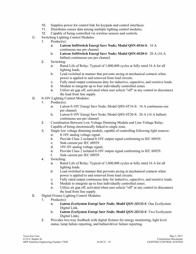
Texas Eye Care May 5, 2017 6116 S. Staples St. Construction Documents MEP Solutions Engineering Number 17020 26 09 23 - 19 LIGHTING CONTROL SYSTEM
10. Supplies power for control link for keypads and control interfaces. 11. Distributes sensor data among multiple lighting control modules. 12. Capable of being controlled via wireless sensors and controls.
C. Switching Lighting Control Modules: 1. Product(s):
a. Lutron SoftSwitch Energi Savr Node; Model QSN-4S16-S: 16 A continuous-use per channel.
b. Lutron SoftSwitch Energi Savr Node; Model QSN-4S20-S: 20 A (16 A ballast) continuous-use per channel.
2. Switching: a. Rated Life of Relay: Typical of 1,000,000 cycles at fully rated 16 A for all
lighting loads. b. Load switched in manner that prevents arcing at mechanical contacts when
power is applied to and removed from load circuits. c. Fully rated output continuous duty for inductive, capacitive, and resistive loads. d. Module to integrate up to four individually controlled zones. e. Utilize air gap off, activated when user selects "off" at any control to disconnect
the load from line supply. D. 0-10V Lighting Control Modules:
1. Product(s): a. Lutron 0-10V Energi Savr Node; Model QSN-4T16-S: 16 A continuous-use
per channel. b. Lutron 0-10V Energi Savr Node; Model QSN-4T20-S: 20 A (16 A ballast)
continuous-use per channel. 2. Coordination Between Low Voltage Dimming Module and Line Voltage Relay:
Capable of being electronically linked to single zone. 3. Single low voltage dimming module; capable of controlling following light sources:
a. 0-10V analog voltage signal. b. Provide Class 2 isolated 0-10V output signal conforming to IEC 60929. c. Sink current per IEC 60929. d. 10V-0V analog voltage signal. e. Provide Class 2 isolated 0-10V output signal conforming to IEC 60929. f. Sink current per IEC 60929.
4. Switching: a. Rated Life of Relay: Typical of 1,000,000 cycles at fully rated 16 A for all
lighting loads. b. Load switched in manner that prevents arcing at mechanical contacts when
power is applied to and removed from load circuits. c. Fully rated output continuous duty for inductive, capacitive, and resistive loads. d. Module to integrate up to four individually controlled zones. e. Utilize air gap off, activated when user selects "off" at any control to disconnect
the load from line supply. E. Digital Fixture Lighting Control Modules:
1. Product(s): a. Lutron EcoSystem Energi Savr Node; Model QSN-1ECO-S: One EcoSystem
Digital Link. b. Lutron EcoSystem Energi Savr Node; Model QSN-2ECO-S: Two EcoSystem
Digital Links. 2. Provides two-way feedback with digital fixtures for energy monitoring, light level
status, lamp failure reporting, and ballast/driver failure reporting.

Texas Eye Care May 5, 2017 6116 S. Staples St. Construction Documents MEP Solutions Engineering Number 17020 26 09 23 - 20 LIGHTING CONTROL SYSTEM
3. Provide testing capability using manual override buttons. 4. Each low-voltage digital communication link to support up to 64 ballasts or LED
drivers capable of NFPA 70 Class 1 or Class 2 installation. 2.09 DIGITAL DIMMING BALLAST AND SWITCHING MODULES (LUTRON ECOSYSTEM)
A. Provide digital dimming ballast and switching modules as indicated or as required to control the loads as indicated.
B. General Requirements: 1. Provide continuous 3-wire signal dimming to compatible 3-wire electronic dimming
ballasts. 2. Utilize air gap off to disconnect the load from line supply. 3. Connect without interface to:
a. Occupancy sensor. b. Daylight sensor. c. Personal control input (wall station or infrared receiver).
4. Generate digital communication commands to distribute ballast and sensor data on the digital bus.
5. If power is interrupted and subsequently restored, lights automatically return to the setting prior to power interruption.
6. Each ballast module responds independently to: a. Up to 32 occupancy sensors. b. Up to 64 personal control inputs. c. Two daylight sensors.
7. Unique internal reference number visible displayed on module cover. 8. Averages two independent daylight harvesting inputs internally. 9. Responds to digital load shed command.
a. Sets high end trim. b. Automatically scales light output proportional to load shed command.
(Example: If light output is at 30 percent and a load shed command of 10 percent is received, the ballast to automatically set the maximum light output at 90 percent and lower current light output by 3 percent to 27 percent).
10. Provide integral fault protection to prevent ballast module failure in the event of a mis-wire.
C. Product(s): 1. 3-Wire Ballast Module, 2 Amp; Lutron EcoSystem Model C5-BMF-2A:
a. Integrates up to 2 amps of 3-wire electronic dimming ballasts into EcoSystem digital control system as a single zone.
2. 3-Wire Ballast Module, 16 Amp; Lutron EcoSystem Model C5-BMJ-16A: a. Integrates up to 16 amps of 3-wire electronic dimming ballasts into EcoSystem
digital control system as a single zone. b. Integrates up to 16 amps of switched high intensity discharge (HID) lighting
load into EcoSystem digital control system as a single zone. 3. Switching Power Module, 16 Amp; Lutron EcoSystem Model C5-XPJ-16A:
a. Integrates up to 16 amps of high in-rush lighting load (magnetic fluorescent ballast, electronic fluorescent ballast, HID, incandescent, magnetic low-voltage, electronic low-voltage, neon/cold cathode and motor loads) into EcoSystem digital control system as a single zone.
2.10 LIGHTING MANAGEMENT HUBS A. Product: Lutron Quantum Light Management Hub. B. Provided in a pre-assembled NEMA listed enclosure with terminal blocks listed for field
wiring.
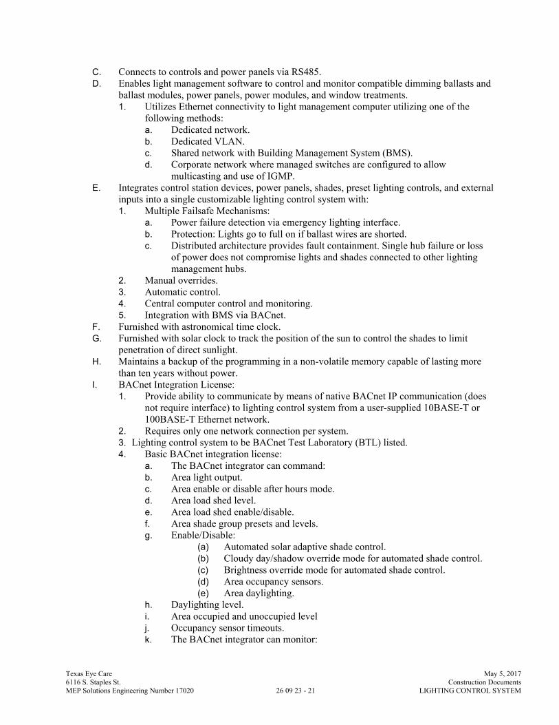
Texas Eye Care May 5, 2017 6116 S. Staples St. Construction Documents MEP Solutions Engineering Number 17020 26 09 23 - 21 LIGHTING CONTROL SYSTEM
C. Connects to controls and power panels via RS485. D. Enables light management software to control and monitor compatible dimming ballasts and
ballast modules, power panels, power modules, and window treatments. 1. Utilizes Ethernet connectivity to light management computer utilizing one of the
following methods: a. Dedicated network. b. Dedicated VLAN. c. Shared network with Building Management System (BMS). d. Corporate network where managed switches are configured to allow
multicasting and use of IGMP. E. Integrates control station devices, power panels, shades, preset lighting controls, and external
inputs into a single customizable lighting control system with: 1. Multiple Failsafe Mechanisms:
a. Power failure detection via emergency lighting interface. b. Protection: Lights go to full on if ballast wires are shorted. c. Distributed architecture provides fault containment. Single hub failure or loss
of power does not compromise lights and shades connected to other lighting management hubs.
2. Manual overrides. 3. Automatic control. 4. Central computer control and monitoring. 5. Integration with BMS via BACnet.
F. Furnished with astronomical time clock. G. Furnished with solar clock to track the position of the sun to control the shades to limit
penetration of direct sunlight. H. Maintains a backup of the programming in a non-volatile memory capable of lasting more
than ten years without power. I. BACnet Integration License:
1. Provide ability to communicate by means of native BACnet IP communication (does not require interface) to lighting control system from a user-supplied 10BASE-T or 100BASE-T Ethernet network.
2. Requires only one network connection per system. 3. Lighting control system to be BACnet Test Laboratory (BTL) listed. 4. Basic BACnet integration license:
a. The BACnet integrator can command: b. Area light output. c. Area enable or disable after hours mode. d. Area load shed level. e. Area load shed enable/disable. f. Area shade group presets and levels. g. Enable/Disable:
(a) Automated solar adaptive shade control. (b) Cloudy day/shadow override mode for automated shade control. (c) Brightness override mode for automated shade control. (d) Area occupancy sensors. (e) Area daylighting.
h. Daylighting level. i. Area occupied and unoccupied level j. Occupancy sensor timeouts. k. The BACnet integrator can monitor:
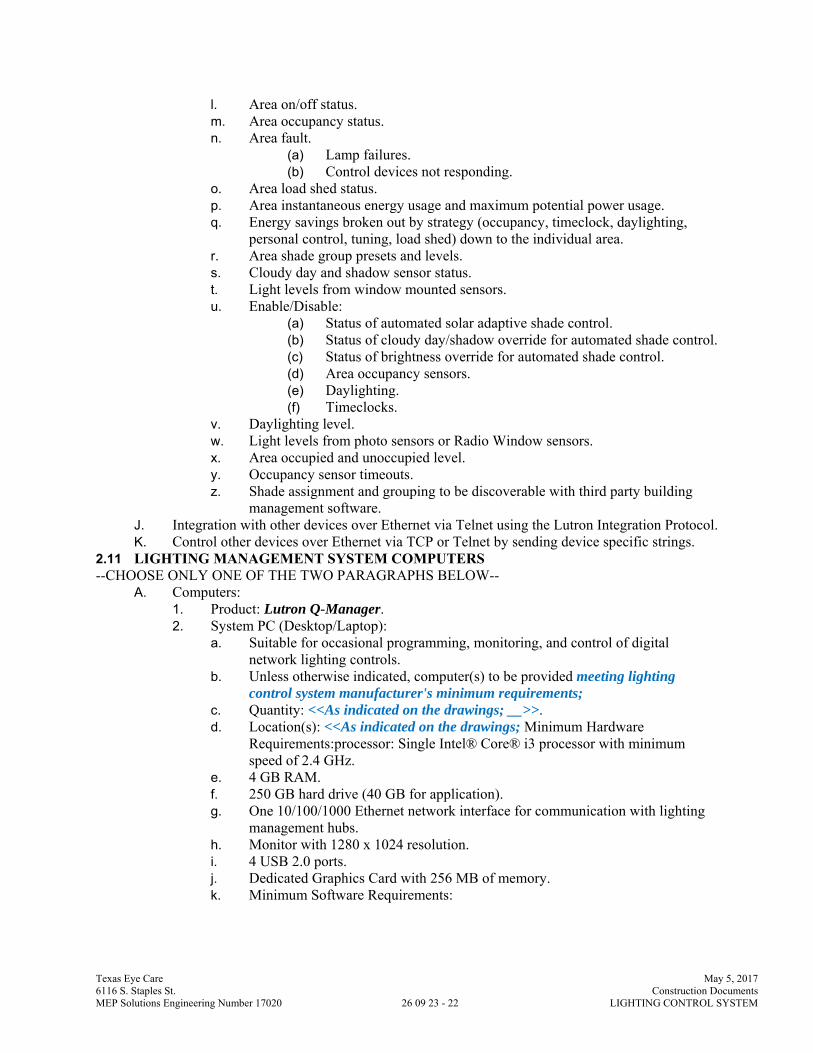
Texas Eye Care May 5, 2017 6116 S. Staples St. Construction Documents MEP Solutions Engineering Number 17020 26 09 23 - 22 LIGHTING CONTROL SYSTEM
l. Area on/off status. m. Area occupancy status. n. Area fault.
(a) Lamp failures. (b) Control devices not responding.
o. Area load shed status. p. Area instantaneous energy usage and maximum potential power usage. q. Energy savings broken out by strategy (occupancy, timeclock, daylighting,
personal control, tuning, load shed) down to the individual area. r. Area shade group presets and levels. s. Cloudy day and shadow sensor status. t. Light levels from window mounted sensors. u. Enable/Disable:
(a) Status of automated solar adaptive shade control. (b) Status of cloudy day/shadow override for automated shade control. (c) Status of brightness override for automated shade control. (d) Area occupancy sensors. (e) Daylighting. (f) Timeclocks.
v. Daylighting level. w. Light levels from photo sensors or Radio Window sensors. x. Area occupied and unoccupied level. y. Occupancy sensor timeouts. z. Shade assignment and grouping to be discoverable with third party building
management software. J. Integration with other devices over Ethernet via Telnet using the Lutron Integration Protocol. K. Control other devices over Ethernet via TCP or Telnet by sending device specific strings.
2.11 LIGHTING MANAGEMENT SYSTEM COMPUTERS --CHOOSE ONLY ONE OF THE TWO PARAGRAPHS BELOW--
A. Computers: 1. Product: Lutron Q-Manager. 2. System PC (Desktop/Laptop):
a. Suitable for occasional programming, monitoring, and control of digital network lighting controls.
b. Unless otherwise indicated, computer(s) to be provided meeting lighting control system manufacturer's minimum requirements;
c. Quantity: <<As indicated on the drawings; __>>. d. Location(s): <<As indicated on the drawings; Minimum Hardware
Requirements:processor: Single Intel® Core® i3 processor with minimum speed of 2.4 GHz.
e. 4 GB RAM. f. 250 GB hard drive (40 GB for application). g. One 10/100/1000 Ethernet network interface for communication with lighting
management hubs. h. Monitor with 1280 x 1024 resolution. i. 4 USB 2.0 ports. j. Dedicated Graphics Card with 256 MB of memory. k. Minimum Software Requirements:

Texas Eye Care May 5, 2017 6116 S. Staples St. Construction Documents MEP Solutions Engineering Number 17020 26 09 23 - 23 LIGHTING CONTROL SYSTEM
l. Licensed installation of US English 64-bit Microsoft® Windows® 7 Professional with Service Pack 1, US English 64-bit Microsoft® Windows® 8 Professional, or US English 64-bit Microsoft® Windows® 8.1 Professional.
m. Microsoft® Internet Information Services (IIS) 7 or later. n. Microsoft® Internet Explorer 9 or later. o. Microsoft® .NET Framework 3.5. p. Microsoft® .NET Framework 4.5.
3. Server: a. Suitable for 24 hour per day, 7 day per week programming, monitoring, control,
and data logging of digital-network lighting controls. b. Suitable to handle client machine request in multi-computer systems. c. Unless otherwise indicated, computer to be provided meeting lighting control
system manufacturer's minimum requirements; d. Minimum Hardware Requirements: e. Processor: Quad Core Intel® Xeon®. f. 8 GB Ram. g. 250 GB hard drive (40 GB for application and database). h. Two 10/100/1000 Ethernet network interfaces - one for communication with
lighting management hubs and one for communication with corporate intranet to allow access from system PCs and/or energy saving display terminals. Only one Ethernet network interface is required if all lighting management hubs and client PCs are on the same network.
i. Monitor with 1280 x 1024 resolution. j. 4 USB 2.0 ports. k. Dedicated Graphics Card with 256 MB of memory (only required if running
client software from the server). l. Minimum Software Requirements: m. Licensed installation of US English 64-bit Microsoft® Windows® Server 2008
R2, Windows Server 2012 R1, or Windows Server 2012 R2. n. Microsoft® Internet Information Services (IIS) 7 or later. o. Microsoft® Internet Explorer 9 or later. p. Microsoft® .NET Framework 3.5. q. Microsoft® .NET Framework 4.5.
2.12 LIGHTING MANAGEMENT SYSTEM SOFTWARE A. Provide system software license and hardware that is designed, tested, manufactured, and
warranted by a single manufacturer. a. Shade grouping. b. Equipment schedule. c. Equipment assignment to lighting management hubs. d. Daylighting design. e. Define the configuration for the following in each area: f. Lighting scenes. g. Shade group presets. h. Control station devices. i. Interface and integration equipment. j. Occupancy/after hours. k. Partitioning. l. Daylighting. m. Emergency lighting. n. Night lights.
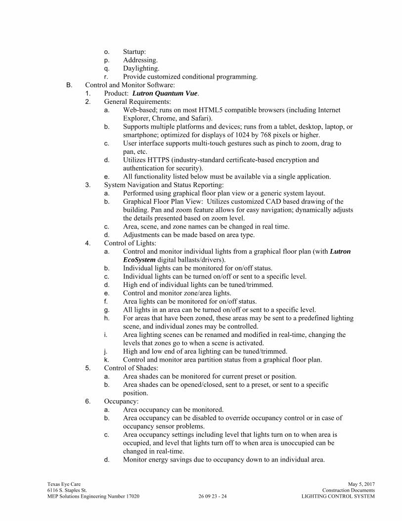
Texas Eye Care May 5, 2017 6116 S. Staples St. Construction Documents MEP Solutions Engineering Number 17020 26 09 23 - 24 LIGHTING CONTROL SYSTEM
o. Startup: p. Addressing. q. Daylighting. r. Provide customized conditional programming.
B. Control and Monitor Software: 1. Product: Lutron Quantum Vue. 2. General Requirements:
a. Web-based; runs on most HTML5 compatible browsers (including Internet Explorer, Chrome, and Safari).
b. Supports multiple platforms and devices; runs from a tablet, desktop, laptop, or smartphone; optimized for displays of 1024 by 768 pixels or higher.
c. User interface supports multi-touch gestures such as pinch to zoom, drag to pan, etc.
d. Utilizes HTTPS (industry-standard certificate-based encryption and authentication for security).
e. All functionality listed below must be available via a single application. 3. System Navigation and Status Reporting:
a. Performed using graphical floor plan view or a generic system layout. b. Graphical Floor Plan View: Utilizes customized CAD based drawing of the
building. Pan and zoom feature allows for easy navigation; dynamically adjusts the details presented based on zoom level.
c. Area, scene, and zone names can be changed in real time. d. Adjustments can be made based on area type.
4. Control of Lights: a. Control and monitor individual lights from a graphical floor plan (with Lutron
EcoSystem digital ballasts/drivers). b. Individual lights can be monitored for on/off status. c. Individual lights can be turned on/off or sent to a specific level. d. High end of individual lights can be tuned/trimmed. e. Control and monitor zone/area lights. f. Area lights can be monitored for on/off status. g. All lights in an area can be turned on/off or sent to a specific level. h. For areas that have been zoned, these areas may be sent to a predefined lighting
scene, and individual zones may be controlled. i. Area lighting scenes can be renamed and modified in real-time, changing the
levels that zones go to when a scene is activated. j. High and low end of area lighting can be tuned/trimmed. k. Control and monitor area partition status from a graphical floor plan.
5. Control of Shades: a. Area shades can be monitored for current preset or position. b. Area shades can be opened/closed, sent to a preset, or sent to a specific
position. 6. Occupancy:
a. Area occupancy can be monitored. b. Area occupancy can be disabled to override occupancy control or in case of
occupancy sensor problems. c. Area occupancy settings including level that lights turn on to when area is
occupied, and level that lights turn off to when area is unoccupied can be changed in real-time.
d. Monitor energy savings due to occupancy down to an individual area.

Texas Eye Care May 5, 2017 6116 S. Staples St. Construction Documents MEP Solutions Engineering Number 17020 26 09 23 - 25 LIGHTING CONTROL SYSTEM
7. Daylighting: a. Daylighting can be enabled/disabled. Can be used to override the control
currently taking place in the space. b. Daylight calibration can be adjusted for each daylit area. c. Daylight status can be monitored. d. Monitor energy savings due to daylight harvesting down to an individual area.
8. Load Shedding; Lutron IntelliDemand: Allows the building manager to monitor whole building lighting power usage and apply a customized load shed reduction to selected areas, thereby reducing a building's power usage; load shedding triggered via Quantum Vue software or BACnet.
9. Scheduling: Schedule time of day and astronomic time clock events to automate functions. a. Adjust or disable a single occurrence of a repeating scheduled event. b. Easily monitor and adjust scheduled events using a weekly calendar view.
10. Reporting: Provide reporting capability that allows the building manager to gather real-time and historical information about the system as follows: a. Energy Reports: Show a comparison of cumulative energy used over a period
of time for one or more areas. b. Power Reports: Show power usage trend over a period of time for one or more
areas. c. Energy Density Report: Show energy usage in W/sq ft. d. Energy Savings By Strategy Report: Show energy savings for any area broken
down by strategy (tuning, occupancy, daylighting, scheduled events, personal control, and load shedding).
e. Space Utilization/Occupancy Reports: Show historical occupancy over a period of time for one or more areas using a graphical floor plan, generic system layout, and/or graphs and charts.
f. Activity Report: Show what activity has taken place over a period of time for one or more areas. Activity includes occupant activities (e.g. wall controls being pressed), building manager operation (e.g. controlling/changing areas using the control and monitor tool), and device failures (e.g. keypads or ballasts that are not responding).
g. Includes shade related activities (e.g. automatic movements from Hyperion automated shade algorithm, manual overrides from personal controls, automatic overrides from sensors).
h. Lamp Failure Report: Shows which areas are currently reporting lamp failures. i. Shade Level Report: Shows the shade level for any shade group in the system
over any historical 24 hour period. j. Shade Position Report: Shows the percentage of time shade groups in the
system are at each position. k. Sensor Level Report: Shows the light level in footcandles of any photosensor in
the system. l. Alert Activity Report: Capable of generating historical reports of all alert
activity within the system. 11. Diagnostics: Allows the building manager to check on the status of all equipment in
the lighting control system. Devices to be listed with a reporting status of OK, missing, or unknown.
12. Alerts and Alarms: Monitors the system for designated events/triggers and automatically generates alerts according to configured response criteria. a. Capable of monitoring for the following events/triggers:
Texas Eye Care May 5, 2017 6116 S. Staples St. Construction Documents MEP Solutions Engineering Number 17020 26 09 23 - 26 LIGHTING CONTROL SYSTEM
b. A failed piece of equipment (e.g. ballast, control, sensor, etc.); alert cleared when equipment is replaced.
c. A lamp outage (for compatible EcoSystem digital electronic dimming ballasts only); alert cleared when lamp is replaced.
d. Low battery conditions in battery-operated sensors and controls; alert cleared when battery is replaced.
e. Luminaires with lamp operating hours in excess of designated time. f. A load shed event; alert generated for beginning and end of trigger. g. Energy usage higher than designated threshold target. h. Potential light level condition discrepancies (daylight sensors not agreeing with
expected lighting status). i. Potential sensor failures (Radio Window sensors that have not seen a change in
light level). j. View alerts on a customized graphical floor plan. k. Capable of generating alerts through visible changes in software or through
email messages. l. Capable of customizing the frequency of alerts and providing notifications
immediately or through daily, weekly, or monthly summaries. m. Capable of sending different alerts to different system users. n. Capable of generating historical reports of all alert activity within the system.
13. Administration: a. Users: Allows new user accounts to be created and existing user accounts to be
edited. b. Supports Active Directory (LDAP) tying user accounts to network accounts. c. Area and feature access can be restricted based on login credentials with
assigned levels of access rights (Monitor, Control Only, Control and Edit, Admin) and customized access levels available.
14. Quick Controls: Create shortcuts to activate customized system-wide actions, such as updating lighting and/or shade levels.
15. Provides control/monitoring of partition status to automatically reconfigure how the space operates based on the partition's open/closed status.
16. Variables: Used for custom program of a system and/or to signal a third party system. Any change may cause a change in the behavior of the system. a. View the current state of system variables across subsystems. b. Update the current variable state across all subsystems.
17. Device Lock/Unlock: Allows the building manager to lock control station devices to prevent building occupants from activating their programming (button presses), until they are unlocked. a. Keypads can be locked to help ensure occupants cannot change light and shade
levels in a public space during specific events or business hours. b. Keypads can be unlocked after events/during after hours to allow maintenance,
cleaning, security, and others to perform their tasks without needing to contact a building manager.
18. Software to be capable of displaying: a. Current savings in percent and kW. b. Historic energy savings in kWh saved, money saved, coal not burned, and
carbon dioxide not emitted. c. Historical views in time periods of three hours, one day, one week, one month,
and one year.
Texas Eye Care May 5, 2017 6116 S. Staples St. Construction Documents MEP Solutions Engineering Number 17020 26 09 23 - 27 LIGHTING CONTROL SYSTEM
d. Configurable energy usage baseline and user-defined working hours for energy saving calculations.
e. Comparisons of historical periods (days, weeks, months, years). f. Local weather conditions.
C. Web Services Integration License: 1. Provide ability to communicate by means of XML web services 2. Web services integrator can monitor:
a. Area instantaneous power usage. b. Area instantaneous power savings. c. Area energy savings. d. Area energy usage. e. Area maximum power usage.
3. Supports both push and pull for integration with third party systems and energy dashboards.
D. Quantum Mobile Control and Programming Software License: 1. Allows mobile control and programming of Quantum system via an Apple iPad or
Windows 10 tablets/PCs. 2. Provides users the ability to:
a. Control and monitor area lighting scenes, zones, and shade presets. b. Easily identify zones and shade groups. c. Edit area lighting scenes, shade presets, scene fade rates, and scene delay rates. d. Restrict user access by area. e. Restrict users from ability to make changes.
3. Connects to Quantum system via: a. An Ethernet connection directly to the processor or through the computer
(server) in the system. b. Wi-Fi.
E. Personal Web-Based Control Software: F. DMX Input Software License:
1. Product: Lutron Model QSW-DMX-IN software license for DMX input; no additional hardware required.
2. Provides ability to map a single zone intensity to a single DMX512 lighting channel. 3. DMX input control can be enabled and disabled on an area-by-area basis. 4. Supports zone chaining for partitioned spaces. 5. Supports a sustained rate of up to five constantly changing channels at any one time.
G. Automated Shade Control Software: 2.13 CONTROL STATIONS
A. Provide control stations with configuration as indicated or as required to control the loads as indicated.
B. Wired Control Stations: 1. General Requirements:
a. Power: Class 2 (low voltage). b. UL listed. c. Provide faceplates with concealed mounting hardware. d. Borders, logos, and graduations to use laser engraving or silk-screened graphic
process that chemically bonds graphics to faceplate, resistant to removal by scratching and cleaning.
e. Finish: White, unless otherwise indicated; 2. Multi-Scene Wired Control:
a. General Requirements:

Texas Eye Care May 5, 2017 6116 S. Staples St. Construction Documents MEP Solutions Engineering Number 17020 26 09 23 - 28 LIGHTING CONTROL SYSTEM
b. Allows control of any devices part of the lighting control system. c. Allows for easy reprogramming without replacing unit. d. Replacement of units does not require reprogramming. e. Communications: Utilize RS485 wiring for low-voltage communication. f. Engrave keypads with button, zone, and scene descriptions; to be selected by
Architect; 3. Software Configuration:
(a) Customizable control station device button functionality: (1) Buttons can be programmed to perform single defined
action. (2) Buttons can be programmed to perform defined action on
press and defined action on release. (3) Buttons can be programmed using conditional logic off of a
state variable such as time of day or partition status. (4) Buttons can be programmed to perform automatic sequence
of defined actions. (5) Capable of deactivating select keypads to prevent accidental
changes to light levels. (6) Buttons can be programmed for raise/lower of defined
loads. (7) Buttons can be programmed to toggle defined set of loads
on/off. b. Status LEDs:
(a) Upon button press, LEDs to immediately illuminate. (b) LEDs to reflect the true system status. LEDs to remain illuminated
if the button press was properly processed or LEDs to turn off if the button press was not processed.
(c) Support logic that defines when LED is illuminated: (1) Scene logic (logic is true when all zones are at defined
levels). (2) Room logic (logic is true when at least one zone is on). (3) Pathway logic (logic is true when at least one zone is on). (4) Last scene (logic is true when spaces are in defined scenes).
c. Wired Keypads; Lutron seeTouch QS Keypads: d. Style: Architectural Insert Style; e. Communications: Utilize RS485 wiring for low-voltage communications link. f. Mounting: Wallbox or low-voltage mounting bracket; provide wall plates with
concealed mounting hardware. g. Button/Engraving Backlighting:
(a) Utilize backlighting for buttons and associated engraving to provide readability under all light conditions.
(b) Backlight intensity adjustable via programming software. h. Design keypads to allow field-customization of button color, configuration, and
engraving using field-changeable replacement kits. i. Contact Closure Interface: Provide two contact closure inputs on back of unit
which provide independent functions from front buttons; accepts both momentary and maintained contact closures.
j. Terminal block inputs to be over-voltage and miswire-protected against wire reversals and shorts.
k. Provide integral infrared receiver for personal control<< where indicated;

Texas Eye Care May 5, 2017 6116 S. Staples St. Construction Documents MEP Solutions Engineering Number 17020 26 09 23 - 29 LIGHTING CONTROL SYSTEM
l. Wired Keypads; Lutron Architrave QS Keypads: m. Mounting: Wallbox; Lutron Architrave Wallbox; provide wall plates with
concealed mounting hardware. n. Design keypads to allow field-customization of button color, configuration, and
engraving using field-changeable replacement kits. o. Contact Closure Interface: Provide two contact closure inputs on back of unit
which provide independent functions from front buttons; accepts both momentary and maintained contact closures.
p. Terminal block inputs to be over-voltage and miswire-protected against wire reversals and shorts.
q. Wired Keypads; Lutron Signature Series QS Keypads: r. Mounting: Wallbox; Lutron Signature Series Wallbox; provide wall plates
with concealed mounting hardware. s. Button/Engraving Backlighting:
(a) Utilize backlighting for buttons and associated engraving to provide readability under all light conditions.
(b) Backlight intensity adjustable via programming software. t. Design keypads to allow field-customization of button color, configuration, and
engraving using field-changeable replacement kits. u. Contact Closure Interface: Provide two contact closure inputs on back of unit
which provide independent functions from front buttons; accepts both momentary and maintained contact closures.
v. Terminal block inputs to be over-voltage and miswire-protected against wire reversals and shorts.
w. Wired Keypads; Lutron QS Wired Palladiom Wallstations: x. Style: Architectural Style y. Mounting: Wallbox; provide wall plates with concealed mounting hardware. z. Buttons and Faceplate:
(a) Buttons to be greater than 0.65 inch (16.5 mm) in height to provide large target area for ease of use and actuation.
(b) Front of buttons to be flush with faceplate. (c) Buttons and faceplate to be of the same material and finish (e.g.
plastic/plastic, glass/glass, metal/metal). (d) Buttons to depress and provide tactile feedback of a successful
button push. Controls utilizing capacitive or resistive touch technology are not acceptable.
(e) Gaps to be less than 0.007 inch (0.18 mm) between buttons and less than 0.15 inch (3.8 mm) between buttons and faceplate.
aa. Button/Engraving Backlighting: (a) Backlighting to be visible through engraved text to provide clear
readability in a variety of lighting conditions. (b) Indicate active scene through the intensity of the backlighting
(brighter backlit text indicates the active state). (c) Backlight intensity adjustable via programming software; capable
of dynamic adjustment during usage based on conditional logic (time of day, button press, etc.).
(d) Backlight intensity automatically adjusts based on room ambient light level.
bb. Design keypads to allow field-customization of button color and engraving using field-changeable replacement kits.

Texas Eye Care May 5, 2017 6116 S. Staples St. Construction Documents MEP Solutions Engineering Number 17020 26 09 23 - 30 LIGHTING CONTROL SYSTEM
cc. Terminal block inputs to be over-voltage and miswire-protected against wire reversals and shorts.
4. Single-Scene or Zoned Wired Control: a. Product: Lutron Pico Wired Control. b. Turn an individual fixture or group of fixtures on and off. c. Raise and lower light levels. d. Recall favorite light levels.
5. Four-Button Preset Wallstation: a. Product: Lutron EcoSystem CC-4BRL Four-Button Control. b. Recall four scenes plus all on or all off for one group of fixtures. c. Master raise/lower control for entire group of fixtures. d. Integral IR receiver for personal control. e. Immediate local LED response upon button activation to indicate that a system
command has been requested. 6. Wired Keyswitch:
a. Product: Lutron QS Keyswitch. b. Configuration: c. Three position, momentary, center position key removal; Lutron Model
QSWS2-KSI-3MOC. d. Three position, maintained, center position key removal; Lutron Model
QSWS2-KSI-3MAC. e. Two position, maintained, center position key removal; Lutron Model QSWS2-
KSI-2MAC. f. Two position, maintained, any position key removal; Lutron Model QSWS2-
KSI-2MAA. g. Allows control of any devices part of the lighting control system. h. Communications: Utilize RS485 wiring for low-voltage communications link. i. Functionality: j. Allows for easy reprogramming without replacing unit. k. Requires key insertion to activate actions. l. Engrave keypads with button, zone, and scene descriptions to be selected by
Architect; m. Software Configuration: n. Customizable control station device button functionality:
(a) Key positions can be programmed to perform single defined action.
(b) Key positions can be programmed using conditional logic off of a state variable such as time of day or partition status.
7. Single Touch Slider Control: a. Product: Lutron GrafikT QS Slider. b. Allows control of any single lighting zone in the system. c. Communications: Utilize RS485 wiring for low-voltage communications link. d. Switch Control: Single-touch LED bar for on/off operation. e. Dimmer Control: Single touch LED bar with one portion of bar for on/off
operation and one portion for dimmer adjustment. f. Single touch of light level adjustment control portion of LED bar raises/lowers
lights, with new level becoming the current preset level. g. When off, single touch of on/off control portion of LED bar raises lights to
preset level.
Texas Eye Care May 5, 2017 6116 S. Staples St. Construction Documents MEP Solutions Engineering Number 17020 26 09 23 - 31 LIGHTING CONTROL SYSTEM
h. When on, single touch of on/off control portion of LED bar initiates long fade to off.
i. Provides audible feedback for touch control confirmation. j. LED bar indicates on/off status and current light level, and functions as locator
light when dimmer is off. k. Provides for customized adjustment of dimmer functions via programming
software: (a) High/low end trims. (b) LED brightness. (c) Sound on/off. (d) Off fade time. (e) On fade time. (f) Preset lock capability.
8. Analog Slider Control: a. Product: Lutron QS Slider Control. b. Allows control of any lighting zone in the system via intuitive analog slider
control. c. Communications: Utilize RS485 wiring for low-voltage communications link. d. Available in 1 to 16 zone configurations. e. Available with or without a take command switch to activate the slider scene. f. Optional keypad ganging. g. Slider zones can be chained in partitioned spaces. h. Engrave keypads with button, zone, and scene descriptions to be selected by
Architect; i. Functionality: j. Full range dimming of individual zones or groups of zones. k. Zone levels indicated by slider position. l. Integrates with multi-scene wired control.
C. Wireless (Radio Frequency) Controls: 1. Product(s):
a. 2-Button Control with Night Light; Lutron Pico Wireless Control Model PJN-2B.
2. _3-Button with Raise/Lower Control; <<Lutron Pico Wireless Control Model PJ2-3BRL; a. Button Marking: <<Light (icons); Shade (text); Shade (icons b. 3-Button with Raise/Lower Control and Night Light; Lutron Pico Wireless
Control Model PJN-3BRL. c. Button Marking: <<Zone controls (light); Zone controls (shade); Scene
keypads (light); Scene keypads (shade d. Wallbox Adapter; Lutron Model PICO-WBX-ADAPT.
3. Quantity: <<As indicated on the drawings; 4. Communicates via radio frequency to compatible dimmers, switches, and plug-in
modules. 5. Does not require external power packs, power or communication wiring. 6. Allows for easy reprogramming without replacing unit. 7. Button Programming:
a. Single action. b. Toggle action. c. Defined action on press and defined action on release.
8. Includes LED to indicate button press or programming mode status.
Texas Eye Care May 5, 2017 6116 S. Staples St. Construction Documents MEP Solutions Engineering Number 17020 26 09 23 - 32 LIGHTING CONTROL SYSTEM
9. Mounting: a. Capable of being mounted with a table stand or directly to a wall under a
faceplate. b. Faceplates: Provide concealed mounting hardware.
10. Power: Battery-operated with minimum ten-year battery life. 11. Finish: <<As specified for wall controls in "Device Finishes
2.14 LOW-VOLTAGE CONTROL INTERFACES A. Provide low-voltage control interfaces as indicated or as required to control the loads as
indicated. B. Connects to lighting management hub via RS485. C. UL listed. D. Contact Closure Interface:
1. Product: Lutron Model QSE-IO. 2. The contact closure input device to accept both momentary and maintained contact
closures. 3. The contact closure output device can be configured for maintained or pulsed outputs. 4. Contact closure can be programmed using conditional logic off of a state variable such
as time of day or partition status. E. Wallbox Input Closure Interface:
1. Product: Lutron Model QSE-CI-WCI. 2. Mounts in wallbox behind contact closure keypad to provide interface for up to eight
contact closure inputs. 3. The contact closure input device to accept both momentary and maintained contact
closures. F. RS232 and Ethernet Interface:
1. Product: Lutron Model QSE-CI-NWK-E. 2. Provide ability to communicate via Ethernet or RS232 to audiovisual equipment,
touchscreens, etc. 3. Provide control of:
a. Light scene selections. b. Fine-tuning of light scene levels with raise/lower. c. Shade group presets. d. Fine-tuning of shade preset levels with raise/lower. e. Simulate system wall station button presses and releases.
4. Provide status monitoring of: a. Light scene status. b. Shade group status. c. Wall station button presses and releases. d. Wall station LEDs.
5. Provide ability to send custom output strings. G. DMX Interface:
1. Product: Lutron Model QSE-CI-DMX. 2. Provide ability to:
a. Map a single zone intensity to a single DMX512 lighting channel. b. Map a single zone intensity to three DMX512 channels for RGB/CMY color
control. c. Map a single zone intensity to a single DMX512 integration channel. d. Smoothly transition from one color to another in a cross fade. e. Automatically sequence through a variety of colors. f. Download, program, and customize a color wheel for each unit.

Texas Eye Care May 5, 2017 6116 S. Staples St. Construction Documents MEP Solutions Engineering Number 17020 26 09 23 - 33 LIGHTING CONTROL SYSTEM
H. Sensor Modules: 1. Products:
a. Sensor module with both wired and wireless inputs; Lutron Model QSM2-4W-C.
b. Sensor module with wired inputs only; Lutron Model QSMX-4W-C. c. Sensor module with wireless inputs only; Lutron Model QSM2-XW-C.
2. Wired Modules: a. Provide wired inputs for: b. Occupancy sensors. c. Daylight sensors. d. IR receivers for personal control. e. Digital ballast wall stations.
3. Wireless Modules: a. Provide wireless communication inputs for: b. Occupancy sensors. c. Daylight sensors. d. Wireless controller. e. RF Range: 30 feet (9 m) between sensor and compatible RF receiving devices. f. RF Frequency: 434 MHz; operates in FCC governed frequency spectrum for
periodic operation; continuous transmission spectrum is not permitted. 4. Communicate sensor information to wired low-voltage digital link for use by
compatible devices. 2.15 WIRED SENSORS
A. Wired Occupancy Sensors: 1. General Requirements:
a. Connects directly to compatible ballasts and modules without the need of a power pack or other interface.
b. Turns off or reduces lighting automatically after reasonable time delay when a room or area is vacated by the last person to occupy the space.
c. Accommodates all conditions of space utilization and all irregular work hours and habits.
d. Comply with UL 94. e. Self-Adaptive Sensors: Continually adjusts sensitivity and timing to ensure
optimal lighting control for any use of the space; furnished with field-adjustable controls for time delay and sensitivity to override any adaptive features.
f. Provide capability to: g. Add additional timeout system-wide without need to make local adjustment on
sensor. h. Group multiple sensors. i. Power Failure Memory: Settings and learned parameters to be saved in non-
volatile memory and not lost should power be interrupted and subsequently restored.
j. Furnished with all necessary mounting hardware and instructions. k. Class 2 devices. l. Ceiling-Mounted Sensors: Indicate viewing directions on mounting bracket. m. Wall-Mounted Sensors: Provide swivel-mount base. n. Color: White.
2. Wired Passive Infrared Sensors: a. Utilize multiple segmented lens, with internal grooves to eliminate dust and
residue build-up.
Texas Eye Care May 5, 2017 6116 S. Staples St. Construction Documents MEP Solutions Engineering Number 17020 26 09 23 - 34 LIGHTING CONTROL SYSTEM
b. Ceiling-Mounted Sensors: Provide customizable mask to block off unwanted viewing areas.
c. Product(s): d. Ceiling-Mounted Passive Infrared Sensor, 450 square feet (42 sq m); <<
Lutron Model LOS-CIR-450-WH; or Lutron Model ULOS-CIR-450-WH (BAA-Buy American Act Compliant)>>: Coverage of 450 square feet (42 sq m) with ceiling height of 8 to 12 feet (2.4 to 3.7 m); 360 degree field of view; self-adaptive.
e. <<Type _____ - >>Ceiling-Mounted Passive Infrared Sensor, 1500 square feet (140 sq m); << Lutron Model LOS-CIR-1500-WH; or Lutron Model ULOS-CIR-1500-WH (BAA-Buy American Act Compliant)>>: Coverage of 1500 square feet (140 sq m) with ceiling height of 8 to 12 feet (2.4 to 3.7 m); 360 degree field of view; self-adaptive.
3. Wired Ultrasonic Sensors: a. Utilize an operating frequency of 32 kHz or 40 kHz, crystal-controlled to
operate within plus/minus 0.005 percent tolerance. b. Product(s): c. Ceiling-Mounted Ultrasonic Sensor, 500 square feet (46 sq m); << Lutron
Model LOS-CUS-500-WHCoverage of 500 square feet (46 sq m) with ceiling height of 8 to 12 feet (2.4 to 3.7 m); 180 degree field of view; self-adaptive.
d. Ceiling-Mounted Ultrasonic Sensor, 1000 square feet (93 sq m); << Lutron Model LOS-CUS-1000-WHCoverage of 1,000 square feet (93 sq m) with ceiling height of 8 to 12 feet (2.4 to 3.7 m); 180 degree field of view; self-adaptive.
e. Ceiling-Mounted Ultrasonic Sensor, 2000 square feet (186 sq m); << Lutron Model LOS-CUS-2000-WH; Coverage of 2000 square feet (186 sq m) with ceiling height of 8 to 12 feet (2.4 to 3.7 m); 360 degree field of view; self-adaptive.
4. Wired Dual Technology Sensors: a. Passive Infrared: Utilize multiple segmented lens, with internal grooves to
eliminate dust and residue build-up. b. Ultrasonic: Utilize an operating frequency of 32 kHz or 40 kHz, crystal-
controlled to operate within plus/minus 0.005 percent tolerance. c. Ceiling-Mounted Sensors: Provide customizable mask to block off unwanted
viewing areas. d. Isolated Relay: Provide an internal additional isolated relay with Normally
Open, Normally Closed, and Common outputs for use with HVAC control, Data Logging and other control options<< where indicated>>.
e. Integral Photocell: Provide an integral photocell with adjustable sensitivity to prevent lights from turning on when there is sufficient natural light<< where indicated>>.
f. Product(s), Without Isolated Relay and Integral Photocell: g. Ceiling-Mounted Dual Technology Sensor, 500 square feet (46 sq m); <<
Lutron Model LOS-CDT-500-WHCoverage of 500 square feet (46 sq m) with ceiling height of 8 to 12 feet (2.4 to 3.7 m); 180 degree field of view; self-adaptive.
h. Ceiling-Mounted Dual Technology Sensor, 1000 square feet (93 sq m); << Lutron Model LOS-CDT-1000-WH; Coverage of 1000 square feet (93 sq m) with ceiling height of 8 to 12 feet (2.4 to 3.7 m); 180 degree field of view; self-adaptive.
Texas Eye Care May 5, 2017 6116 S. Staples St. Construction Documents MEP Solutions Engineering Number 17020 26 09 23 - 35 LIGHTING CONTROL SYSTEM
i. Ceiling-Mounted Dual Technology Sensor, 2000 square feet (186 sq m); << Lutron Model LOS-CDT-2000-WH; Coverage of 2000 square feet (186 sq m) with ceiling height of 8 to 12 feet (2.4 to 3.7 m); 360 degree field of view; self-adaptive.
j. << Wall-Mounted Dual Technology Sensor; << Lutron Model LOS-WDT-WH; or Lutron Coverage of 1600 square feet (149 sq m) with ceiling height of 8 to 12 feet (2.4 to 3.7 m); 110 degree field of view; self-adaptive.
B. Sensor Power Packs: 1. Control Wiring Between Sensors and Control Units: Class 2, 18-24 AWG, stranded
UL Classified, PVC insulated or TEFLON jacketed cable suitable for use in plenums, where applicable.
C. Infrared Receivers: 1. Product: Lutron Model EC-IR-WH. 2. Use Class 2 wiring for low voltage communication. 3. Can be replaced without reprogramming. 4. 360 degree reception of wireless infrared remote controls. 5. Immediate local LED response upon reception of handheld transmitter
communication. 6. Mountable on lighting fixtures or recessed acoustical ceiling tiles. 7. Constructed via sonic welding. 8. Color: White.
D. Wired Daylight Sensors: 1. Digital Interior Daylight Sensor:
a. Product: Lutron Model EC-DIR-WH. b. Use Class 2 wiring for low voltage communication. c. Can be replaced without reprogramming. d. Open-loop basis for daylight sensor control scheme. e. Stable output over temperature from 32 degrees F (0 degrees C) to 104 degrees
F (40 degrees C). f. Partially shielded for accurate detection of available daylight to prevent fixture
lighting and horizontal light component from skewing sensor detection. g. Provide linear response from 0 to 500 footcandles. h. Integral IR receiver for personal control. i. Mountable on lighting fixtures or recessed acoustical ceiling tiles. j. Constructed via sonic welding. k. Color: White.
2. Daylight Control Package: a. Product: Lutron CES Series (Lutron CES Analog Sensor, LC8 Controller,
and Power Pack). b. Controller: c. Product: Lutron Model LC8. d. Automatically switches a dry contact according to changes in ambient light
levels. e. Fully adjustable separate high and low setpoints, with an adjustable dead band
between set points to prevent unwanted cycling. f. Input time delay to prevent unwanted cycling due to intermittent light level
fluctuations. g. Signal/setpoint and relay status indication. h. Sensor calibration input. i. Sensors:

Texas Eye Care May 5, 2017 6116 S. Staples St. Construction Documents MEP Solutions Engineering Number 17020 26 09 23 - 36 LIGHTING CONTROL SYSTEM
j. Class 2, three-wire analog devices. k. Provision for zero or offset based signal. l. Indoor Photo Sensors; Lutron Model CES/I: With fresnel lens and 60 degree
cone of response; sensor range of 0 to 750 footcandles. m. Outdoor Photo Sensors; Lutron Model CES/O: Weatherproof, with hood over
aperture to shield sensor from direct sunlight; sensor range of 0 to 750 footcandles.
n. Atrium Photo Sensors; Lutron Model CES/A: With translucent dome and 180 degree field of view; sensor range of 2 to 2,500 footcandles.
o. Skylight Photo Sensors; Lutron Model CES/S: With translucent dome and 180 degree field of view; sensor range of 10 to 7,500 footcandles.
E. Infrared Partition Sensors: 1. Product: Lutron Model GRX-IRPS-WH. 2. Provide contact closure based on status of the partition wall (open/close) enabling
automatic linking of controls. 2.16 WIRELESS SENSORS
A. General Requirements: 1. Operational life of 10 years without the need to replace batteries when installed per
manufacturer's instructions. 2. Communicates directly to compatible RF receiving devices through use of a radio
frequency communications link. 3. Does not require external power packs, power wiring, or communication wiring. 4. Capable of being placed in test mode to verify correct operation from the face of the
unit. 5. RF Range: 30 feet (9 m) between sensor and compatible RF receiving device(s). 6. Electromagnetic Interference/Radio Frequency Interference (EMI/RFI) Limits:
Comply with FCC requirements of CFR, Title 47, Part 15, for Class B application. B. Wireless Occupancy/Vacancy Sensors:
1. General Requirements: a. Provides a clearly visible method of indication to verify that motion is being
detected during testing and that the unit is communicating to compatible RF receiving devices.
b. Utilize multiple segmented lens, with internal grooves to eliminate dust and residue build-up.
c. Sensing Mechanism: Passive infrared coupled with technology for sensing fine motions; Lutron XCT Technology. Signal processing technology detects fine-motion passive infrared (PIR) signals without the need to change the sensor's sensitivity threshold.
d. Provide optional, readily accessible, user-adjustable controls for timeout, automatic/manual-on, and sensitivity.
e. Turns off lighting after reasonable and adjustable time delay once the last person to occupy the space vacates a room or area. Provide adjustable timeout settings of 1, 5, 15, and 30 minutes.
f. Capable of turning dimmer's lighting load on to an optional locked preset level selectable by the user. Locked preset range to be selectable on the dimmer from 1 percent to 100 percent.
g. Color: White. h. Provide all necessary mounting hardware and instructions for both temporary
and permanent mounting.

Texas Eye Care May 5, 2017 6116 S. Staples St. Construction Documents MEP Solutions Engineering Number 17020 26 09 23 - 37 LIGHTING CONTROL SYSTEM
i. Provide temporary mounting means to allow user to check proper performance and relocate as needed before permanently mounting sensor. Temporary mounting method to be design for easy, damage-free removal.
j. Sensor lens to illuminate during test mode when motion is detected to allow installer to verify coverage prior to permanent mounting.
k. Ceiling-Mounted Sensors: l. Provide surface mounting bracket compatible with drywall, plaster, wood,
concrete, and compressed fiber ceilings. m. Provide recessed mounting bracket compatible with drywall and compressed
fiber ceilings. n. Provide customizable mask to block off unwanted viewing areas. o. Wall-Mounted Sensors: Provide wall or corner mounting brackets compatible
with drywall and plaster walls. 2. Wireless Combination Occupancy/Vacancy Sensors:
a. Ceiling-Mounted Sensors: Programmable to operate as an occupancy sensor (automatic-on and automatic-off), an occupancy sensor with low light feature (automatic-on when less than one footcandle of ambient light available and automatic-off), or a vacancy sensor (manual-on and automatic-off).
b. Wall-Mounted Sensors: Programmable to operate as an occupancy sensor (automatic-on and automatic-off), or a vacancy sensor (manual-on and automatic-off).
c. Product(s): d. Ceiling-Mounted Occupancy/Vacancy Sensor; << Lutron Radio Powr Savr
Series, Model LFR2-OCR2B-P-WH; square feet (62.4 sq m) depending on ceiling height from 8 to 12 feet (2.4 to 3.7 m); 360 degree field of view.
e. Wall-Mounted Occupancy/Vacancy Sensor; << Lutron Radio Powr Savr Series, Model LFR2-OWLB-P-WH; Minor motion coverage of 1500 square feet (139.4 sq m) and major motion coverage of 3000 square feet (278.7 sq m) with mounting height of 6 to 8 feet (1.8 to 2.4 m); 180 degree field of view.
f. Corner-Mounted Occupancy/Vacancy Sensor; << Lutron Radio Powr Savr Series, Model LFR2-OKLB-P-WH; Minor motion coverage of 1225 square feet (113.8 sq m) and major motion coverage of 2500 square feet (232.3 sq m) with mounting height of 6 to 8 feet (1.8 to 2.4 m); 90 degree field of view.
g. Hallway Occupancy/Vacancy Sensor; << Lutron Radio Powr Savr Series, Model LFR2-OHLB-P-WH; Major motion coverage of up to 150 feet (45.7 m) with mounting height of 6 to 8 feet (1.8 to 2.4 m); narrow field of view.
3. Wireless Vacancy-Only Sensors: a. Product(s): b. Ceiling-Mounted Vacancy-Only Sensor; << Lutron Radio Powr Savr Series,
Model LFR2-VCR2B-P-WH; Coverage from 324 square feet (30.2 sq m) to 676 square feet (62.4 sq m) depending on ceiling height from 8 to 12 feet (2.4 to 3.7 m); 360 degree field of view.
4. 5. Product: Lutron Model LFR2-DCRB. 6. Open-loop basis for daylight sensor control scheme. 7. Stable output over temperature from 32 degrees F (0 degrees C) to 104 degrees F (40
degrees C). 8. Partially shielded for accurate detection of available daylight to prevent fixture
lighting and horizontal light component from skewing sensor detection. 9. Provide linear response from 0 to 10,000 footcandles.
Texas Eye Care May 5, 2017 6116 S. Staples St. Construction Documents MEP Solutions Engineering Number 17020 26 09 23 - 38 LIGHTING CONTROL SYSTEM
10. Color: White. 11. Mounting:
a. Provide surface mounting bracket compatible with drywall, plaster, wood, concrete, and compressed fiber ceilings.
b. Provide all necessary mounting hardware and instructions for both temporary and permanent mounting.
c. Provide temporary mounting means to allow user to check proper performance and relocate as needed before permanently mounting sensor. Temporary mounting method to be design for easy, damage-free removal.
12. Meets California Title 24 requirements. 2.17 ACCESSORIES
A. Emergency Lighting Interface: 1. Product: Lutron Model LUT-ELI. 2. Provides total system listing to UL 924 when used with lighting control system. 3. Senses all three phases of building power. 4. Provides an output to power panels or digital ballast interfaces if power on any phase
fails and sends all lights controlled by these devices to <<an emergency light level setting;. Lights to return to their previous intensities when normal power is restored.
5. Accepts a contact closure input from a fire alarm control panel. B. Provide power supplies as indicated or as required to power system devices and accessories.
1. Product(s): a. Junction box-mounted power supply for shades, keypads, and accessories, and
for providing additional low voltage power to communication link; Lutron Model QSPS-J-1-50; with miswire and thermal protection.
b. Plug-in power supply for shades, drapery drive units, keypads, and accessories, and for providing additional low voltage power to communication link; Lutron Model QSPS-P1-1-35V; with miswire protection; powered from standard receptacle using cord 6 feet (1.8 m) in length; complies with DOE Level VI regulation.
c. Ten output power supply panel for shades, drapery drive units, keypads and accessories, and for providing additional low voltage power to communication link; Lutron Model QSPS-10PNL; no replaceable fuses required for overload/miswire protection; contains DOE Level VI Compliant power supplies.
d. Power supply for keypads and accessories (not for shades/window treatments), and for providing additional low voltage power to communication link; Lutron Model QSPS-DH-1-75.
C. Provide locking covers for controls <<where indicated; 1. Reversible to allow lock to be located on either side of control. 2. Compatible with IR controls. 3. Does not reduce specified IR range by more than 50 percent of its original
specification. 4. Product(s):
a. 1-gang device for compatible Lutron QS keypads; Lutron Model GRX-1GLC. b. 4-gang device for Lutron Grafik Eye QS main units; Lutron Model QSG-
4GLC. 2.18 SOURCE QUALITY CONTROL
A. See Section 01 4000 - Quality Requirements, for additional requirements. B. Factory Testing; Lutron Standard Factory Testing:
Texas Eye Care May 5, 2017 6116 S. Staples St. Construction Documents MEP Solutions Engineering Number 17020 26 09 23 - 39 LIGHTING CONTROL SYSTEM
1. Perform full-function factory testing on all completed assemblies. Statistical sampling is not acceptable.
2. Perform full-function factory testing on 100 percent of all ballasts and LED drivers. 3. Perform factory audit burn-in of all dimming assemblies and panels at 104 degrees F
(40 degrees C) at full load for two hours. 4. Perform factory burn-in of 100 percent of all ballasts at 104 degrees F (40 degrees C).
PART 3 EXECUTION 3.01 EXAMINATION
A. Verify that field measurements are as shown on the drawings. B. Verify that ratings and configurations of system components are consistent with the
indicated requirements. C. Verify that mounting surfaces are ready to receive system components. D. Verify that conditions are satisfactory for installation prior to starting work.
3.02 INSTALLATION A. Perform work in a neat and workmanlike manner in accordance with NECA 1 and, where
applicable, NECA 130Install products in accordance with manufacturer's instructions. B. Provide dedicated network between lighting management system computer and lighting
management hubs. C. Define each dimmer/relay load type, assign each load to a zone, and set control functions. D. Sensor Locations:
1. Where Lighting Control Manufacturer Sensor Layout and Tuning service is specified in Part 2 under "DIGITAL-NETWORK LIGHTING CONTROL SYSTEM - GENERAL REQUIREMENTS", locate sensors in accordance with layout provided by Lighting Control Manufacturer. Lighting Control Manufacturer may direct Contractor regarding sensor relocation should conditions require a deviation from locations indicated. Where Lighting Control Manufacturer Sensor Layout and Tuning service is not specified, locate sensors in accordance with Drawings.
2. Sensor locations indicated are diagrammatic. Within the design intent, reasonably minor adjustments to locations may be made in order to optimize coverage and avoid conflicts or problems affecting coverage, in accordance with manufacturer's recommendations.
E. Mount exterior daylight sensors to point due north with constant view of daylight. F. Ensure that daylight sensor placement minimizes sensor view of electric light sources.
Locate ceiling-mounted and luminaire-mounted daylight sensors to avoid direct view of luminaires.
G. Automated Shade Control Sensors: 1. Mount rooftop cloudy day sensors to point in the direction of each facade. 2. Ensure that window shadow sensor placement provides an unobstructed view of
outdoors. Do not place at a skylight or above indirect luminaires. H. Lamp Burn-In: Operate lamps at full output for prescribed period per manufacturer's
recommendations prior to use with any dimming controls. Replace lamps that fail prematurely due to improper lamp burn-in.
I. Lamp Lead Lengths: Do not exceed 3 feet (0.9 m) for T4 4-pin compact and T5 BIAX lamps and 7 feet (2.1 m) for T5, T5-HO, T8 U-bend, and T8 linear fluorescent lamps.
J. LED Light Engine/Array Lead Length: Do not exceed 100 feet (31 m). K. System and Network Integration Consultation; Lutron LSC-INT-VISIT: Include <<as part
of the base bid; additional costs for Lighting Control Manufacturer to conduct meeting with facility representative and other related equipment manufacturers to discuss equipment and integration procedures.

Texas Eye Care May 5, 2017 6116 S. Staples St. Construction Documents MEP Solutions Engineering Number 17020 26 09 23 - 40 LIGHTING CONTROL SYSTEM
1. Coordinate scheduling of visit with Lighting Control Manufacturer. Manufacturer recommends that this visit be scheduled early in construction phase, after system purchase but prior to system installation.
L. Identify system components<< in accordance with Section 26 0553>>. 3.03 FIELD QUALITY CONTROL
A. See Section 01 4000 - Quality Requirements, for additional requirements. B. Manufacturer's Startup Services; Lutron Standard Startup Services:
1. Manufacturer's authorized Service Representative to conduct minimum of two site visits to ensure proper system installation and operation.
2. Conduct Pre-Installation visit to review requirements with installer as specified in Part 1 under "Administrative Requirements".
3. Conduct second site visit upon completion of lighting control system to perform system startup and verify proper operation: a. Where Lighting Control Manufacturer Sensor Layout and Tuning service is
specified in Part 2 under “DIGITAL-NETWORK LIGHTING CONTROL SYSTEM – GENERAL REQUIREMENTS”, authorized Service Representative to verify sensor locations, in accordance with layout provided by Lighting Control Manufacturer; Lighting Control Manufacturer may direct Contractor regarding sensor relocation should conditions require a deviation from locations indicated.
b. Verify connection of power wiring and load circuits. c. Verify connection and location of controls. d. Energize lighting management hubs and download system data program. e. Address devices. f. Verify proper connection of panel links (low voltage/data) and address panel. g. Download system panel data to dimming/switching panels. h. Check dimming panel load types and currents and supervise removal of by-pass
jumpers. i. Verify system operation control by control. j. Verify proper operation of manufacturer's interfacing equipment. k. Verify proper operation of manufacturer's supplied PC and installed programs. l. Configure initial groupings of ballast for wall controls, daylight sensors and
occupancy sensors. m. Provide initial rough calibration of sensors; fine-tuning of sensors is
responsibility of Contractor unless provided by Lighting Control Manufacturer as part of Sensor Layout and Tuning service where specified in Part 2 under "DIGITAL-NETWORK LIGHTING CONTROL SYSTEM - GENERAL REQUIREMENTS".
n. Train Owner's representative on system capabilities, operation, and maintenance, as specified in Part 3 under "Closeout Activities".
o. Obtain sign-off on system functions. 3.04 ADJUSTING
A. Sensor Fine-Tuning: Where Lighting Control Manufacturer Sensor Layout and Tuning service is specified in Part 2 under “DIGITAL-NETWORK LIGHTING CONTROL SYSTEM – GENERAL REQUIREMENTS”, Lighting Control Manufacturer to provide up to two additional post-startup on-site service visits for fine-tuning of sensor calibration. Where Lighting Control Manufacturer Sensor Layout and Tuning service is not specified, Contractor to provide fine-tuning of sensor calibration.
3.05 CLEANING

Texas Eye Care May 5, 2017 6116 S. Staples St. Construction Documents MEP Solutions Engineering Number 17020 26 09 23 - 41 LIGHTING CONTROL SYSTEM
A. Clean exposed surfaces to remove dirt, paint, or other foreign material and restore to match original factory finish.
3.06 COMMISSIONING A. See Section 01 9113 for commissioning requirements.
3.07 CLOSEOUT ACTIVITIES A. See Section 01 7800 - Closeout Submittals, for closeout submittals. B. See Section 01 7900 - Demonstration and Training, for additional requirements. C. Demonstration:
1. On-Site Performance-Verification Walkthrough; Lutron LSC-WALK: Include <<as part of the base bid; additional costs for lighting control manufacturer to provide on-site demonstration of system functionality facility representative
D. Training: 1. Include services of manufacturer's authorized Service Representative to perform on-
site training of Owner's personnel on operation, adjustment, and maintenance of lighting control system as part of standard system start-up services. a. Include training on software to be provided:
1) Configuration software used to make system programming and configuration changes.
2) Control and monitor. 3) Energy savings display software. 4) Personal web-based control software.
2. Customer-Site Solution Training Visit; Lutron LSC-TRAINING: Include <<as part of the base bid; additional costs for Lighting Control Manufacturer to provide <<one day(s) of additional on-site system training.
3.08 PROTECTION A. Protect installed products from subsequent construction operations.
3.09 MAINTENANCE A. See Section 01 7000 - Execution Requirements, for additional requirements relating to
maintenance service. B. Software Maintenance Agreement; Lutron LSC-SMA: Include <<as part of the base bid;
additional costs for manufacturer to provide quarterly compatibility testing results for PC-based lighting control software and new patches issued for Microsoft Operating System, Database, and Browser tools. 1. If new Microsoft patches create a software conflict, manufacturer to provide lighting
control software patches to ensure continued operation. C. System Optimization Visit; Lutron LSC-SYSOPT: Include <<as part of the base bid; as an
alternate to the base bid; or _________>> additional costs for Lighting Control System Manufacturer to visit site <<six months; or __________>> after system start-up to evaluate system usage and discuss opportunities to make efficiency improvements that will fit with the current use of the facility.
END OF SECTION
Texas Eye Care May 5, 2017 6116 S. Staples St. Construction Documents MEP Solutions Engineering Number 17020 26 24 16 - 1 PANELBOARDS
SECTION 26 24 16 PANELBOARDS
PART 1 - GENERAL
1.1 RELATED DOCUMENTS
A. Drawings and general provisions of the Contract, including General and Supplementary Conditions and Division 01 Specification Sections, apply to this Section.
1.2 SUMMARY
A. Section Includes:
1. Distribution panelboards. 2. Lighting and appliance branch-circuit panelboards. 3. Electronic-grade panelboards.
1.3 DEFINITIONS
A. SVR: Suppressed voltage rating.
B. TVSS: Transient voltage surge suppressor.
1.4 PERFORMANCE REQUIREMENTS
A. Seismic Performance: Panelboards shall withstand the effects of earthquake motions determined according to SEI/ASCE 7.
1. The term "withstand" means "the unit will remain in place without separation of any parts from the device when subjected to the seismic forces specified."
1.5 SUBMITTALS
A. Product Data: For each type of panelboard, switching and overcurrent protective device, transient voltage suppression device, accessory, and component indicated. Include dimensions and manufacturers' technical data on features, performance, electrical characteristics, ratings, and finishes.
B. Shop Drawings: For each panelboard and related equipment.
1. Include dimensioned plans, elevations, sections, and details. Show tabulations of installed devices, equipment features, and ratings.
2. Detail enclosure types and details for types other than NEMA 250, Type 1. 3. Detail bus configuration, current, and voltage ratings.

Texas Eye Care May 5, 2017 6116 S. Staples St. Construction Documents MEP Solutions Engineering Number 17020 26 24 16 - 2 PANELBOARDS
4. Short-circuit current rating of panelboards and overcurrent protective devices. 5. Detail features, characteristics, ratings, and factory settings of individual overcurrent
protective devices and auxiliary components. 6. Include wiring diagrams for power, signal, and control wiring. 7. Include time-current coordination curves for each type and rating of overcurrent
protective device included in panelboards. Submit on translucent log-log graft paper; include selectable ranges for each type of overcurrent protective device.
C. Qualification Data: For qualified testing agency.
D. Field Quality-Control Reports:
1. Test procedures used. 2. Test results that comply with requirements. 3. Results of failed tests and corrective action taken to achieve test results that comply with
requirements.
E. Panelboard Schedules: For installation in panelboards. Submit final versions after load balancing.
F. Operation and Maintenance Data: For panelboards and components to include in emergency, operation, and maintenance manuals. In addition to items specified in Division 01 Section "Operation and Maintenance Data," include the following:
1. Manufacturer's written instructions for testing and adjusting overcurrent protective devices.
2. Time-current curves, including selectable ranges for each type of overcurrent protective device that allows adjustments.
1.6 QUALITY ASSURANCE
A. Testing Agency Qualifications: Member company of NETA or an NRTL.
1. Testing Agency's Field Supervisor: Currently certified by NETA to supervise on-site testing.
B. Source Limitations: Obtain panelboards, overcurrent protective devices, components, and accessories from single source from single manufacturer.
C. Product Selection for Restricted Space: Drawings indicate maximum dimensions for panelboards including clearances between panelboards and adjacent surfaces and other items. Comply with indicated maximum dimensions.
D. Electrical Components, Devices, and Accessories: Listed and labeled as defined in NFPA 70, by a qualified testing agency, and marked for intended location and application.
E. Comply with NEMA PB 1.
F. Comply with NFPA 70.
Texas Eye Care May 5, 2017 6116 S. Staples St. Construction Documents MEP Solutions Engineering Number 17020 26 24 16 - 3 PANELBOARDS
1.7 DELIVERY, STORAGE, AND HANDLING
A. Remove loose packing and flammable materials from inside panelboards; install temporary electric heating (250 W per panelboard) to prevent condensation.
B. Handle and prepare panelboards for installation according to NEMA PB 1.
1.8 PROJECT CONDITIONS
A. Environmental Limitations:
1. Do not deliver or install panelboards until spaces are enclosed and weathertight, wet work in spaces is complete and dry, work above panelboards is complete, and temporary HVAC system is operating and maintaining ambient temperature and humidity conditions at occupancy levels during the remainder of the construction period.
2. Rate equipment for continuous operation under the following conditions unless otherwise indicated:
a. Ambient Temperature: Not exceeding 23 deg F (minus 5 deg C) to plus 104 deg F (plus 40 deg C).
b. Altitude: Not exceeding 6600 feet (2000 m).
1.9 COORDINATION
A. Coordinate layout and installation of panelboards and components with other construction that penetrates walls or is supported by them, including electrical and other types of equipment, raceways, piping, encumbrances to workspace clearance requirements, and adjacent surfaces. Maintain required workspace clearances and required clearances for equipment access doors and panels.
B. Coordinate sizes and locations of concrete bases with actual equipment provided. Cast anchor-bolt inserts into bases. Concrete, reinforcement, and formwork requirements are specified in Division 03.
1.10 WARRANTY
A. Special Warranty: Manufacturer's standard form in which manufacturer agrees to repair or replace transient voltage suppression devices that fail in materials or workmanship within specified warranty period.
1. Warranty Period: Five years from date of Substantial Completion.
1.11 EXTRA MATERIALS
A. Furnish extra materials that match products installed and that are packaged with protective covering for storage and identified with labels describing contents.

Texas Eye Care May 5, 2017 6116 S. Staples St. Construction Documents MEP Solutions Engineering Number 17020 26 24 16 - 4 PANELBOARDS
1. Keys: Two spares for each type of panelboard cabinet lock. 2. Circuit Breakers Including GFCI and Ground Fault Equipment Protection (GFEP) Types:
Two spares for each panelboard. 3. Fuses for Fused Switches: Equal to 10 percent of quantity installed for each size and
type, but no fewer than three of each size and type. 4. Fuses for Fused Power-Circuit Devices: Equal to 10 percent of quantity installed for
each size and type, but no fewer than three of each size and type.
PART 2 - PRODUCTS
2.1 GENERAL REQUIREMENTS FOR PANELBOARDS
A. Enclosures: Flush- and surface-mounted cabinets.
1. Rated for environmental conditions at installed location.
a. Indoor Dry and Clean Locations: NEMA 250, Type 1. b. Outdoor Locations: NEMA 250, Type 3R. c. Kitchen Areas: NEMA 250, Type 4X, stainless steel. d. Other Wet or Damp Indoor Locations: NEMA 250, Type 4. e. Indoor Locations Subject to Dust, Falling Dirt, and Dripping Noncorrosive
Liquids: NEMA 250, Type 5. 2. Hinged Front Cover: Entire front trim hinged to box and with standard door within
hinged trim cover. 3. Finishes:
a. Panels and Trim: Steel and galvanized steel, factory finished immediately after cleaning and pretreating with manufacturer's standard two-coat, baked-on finish consisting of prime coat and thermosetting topcoat.
b. Back Boxes: Same finish as panels and trim.
4. Directory Card: Inside panelboard door, mounted in transparent card holder.
B. Incoming Mains Location: Top and bottom.
C. Phase, Neutral, and Ground Buses:
1. Material: Hard-drawn copper, 98 percent conductivity. 2. Equipment Ground Bus: Adequate for feeder and branch-circuit equipment grounding
conductors; bonded to box. 3. Isolated Ground Bus: Adequate for branch-circuit isolated ground conductors; insulated
from box. 4. Extra-Capacity Neutral Bus: Neutral bus rated 200 percent of phase bus and UL listed as
suitable for nonlinear loads. 5. Split Bus: Vertical buses divided into individual vertical sections.
D. Conductor Connectors: Suitable for use with conductor material and sizes.

Texas Eye Care May 5, 2017 6116 S. Staples St. Construction Documents MEP Solutions Engineering Number 17020 26 24 16 - 5 PANELBOARDS
1. Material: Hard-drawn copper, 98 percent conductivity. 2. Main and Neutral Lugs: Compression type. 3. Ground Lugs and Bus-Configured Terminators: Compression type. 4. Feed-Through Lugs: Compression type, suitable for use with conductor material. Locate
at opposite end of bus from incoming lugs or main device. 5. Subfeed (Double) Lugs: Compression type suitable for use with conductor material.
Locate at same end of bus as incoming lugs or main device. 6. Gutter-Tap Lugs: Compression type suitable for use with conductor material. Locate at
same end of bus as incoming lugs or main device. 7. Extra-Capacity Neutral Lugs: Rated 200 percent of phase lugs mounted on extra-
capacity neutral bus.
E. Panelboard Short-Circuit Current Rating: Fully rated to interrupt symmetrical short-circuit current available at terminals.
2.2 DISTRIBUTION PANELBOARDS
A. Manufacturers: Subject to compliance with requirements, provide products by one of the following:
B. Basis-of-Design Product: Subject to compliance with requirements, provide product indicated on Drawings or comparable product by one of the following:
1. Eaton Electrical Inc.; Cutler-Hammer Business Unit. 2. Siemens Energy & Automation, Inc. 3. Square D; a brand of Schneider Electric.
C. Panelboards: NEMA PB 1, power and feeder distribution type.
D. Doors: Secured with vault-type latch with tumbler lock; keyed alike.
1. For doors more than 36 inches (914 mm) high, provide two latches, keyed alike.
E. Mains: Circuit breaker or Lugs only.
F. Branch Overcurrent Protective Devices for Circuit-Breaker Frame Sizes 125 A and Smaller: Plug-in circuit breakers.
G. Branch Overcurrent Protective Devices for Circuit-Breaker Frame Sizes Larger Than 125 A: Bolt-on circuit breakers; plug-in circuit breakers where individual positive-locking device requires mechanical release for removal.
2.3 LIGHTING AND APPLIANCE BRANCH-CIRCUIT PANELBOARDS
A. Manufacturers: Subject to compliance with requirements, provide products by one of the following:
B. Basis-of-Design Product: Subject to compliance with requirements, provide product indicated on Drawings or comparable product by one of the following:

Texas Eye Care May 5, 2017 6116 S. Staples St. Construction Documents MEP Solutions Engineering Number 17020 26 24 16 - 6 PANELBOARDS
1. Eaton Electrical Inc.; Cutler-Hammer Business Unit. 2. Siemens Energy & Automation, Inc. 3. Square D; a brand of Schneider Electric.
C. Panelboards: NEMA PB 1, lighting and appliance branch-circuit type.
D. Mains: Circuit breaker or lugs only.
E. Branch Overcurrent Protective Devices: Plug-in circuit breakers, replaceable without disturbing adjacent units.
F. Doors: Concealed hinges; secured with flush latch with tumbler lock; keyed alike.
G. Column-Type Panelboards: Narrow gutter extension, with cover, to overhead junction box equipped with ground and neutral terminal buses.
2.4 DISCONNECTING AND OVERCURRENT PROTECTIVE DEVICES
A. Manufacturers: Subject to compliance with requirements, provide products by one of the following:
B. Basis-of-Design Product: Subject to compliance with requirements, provide product indicated on Drawings or comparable product by one of the following:
1. Eaton Electrical Inc.; Cutler-Hammer Business Unit. 2. Siemens Energy & Automation, Inc. 3. Square D; a brand of Schneider Electric.
C. Molded-Case Circuit Breaker (MCCB): Comply with UL 489, with interrupting capacity to meet available fault currents.
1. Thermal-Magnetic Circuit Breakers: Inverse time-current element for low-level overloads, and instantaneous magnetic trip element for short circuits. Adjustable magnetic trip setting for circuit-breaker frame sizes 250 A and larger.
2. Adjustable Instantaneous-Trip Circuit Breakers: Magnetic trip element with front-mounted, field-adjustable trip setting.
3. Electronic trip circuit breakers with rms sensing; field-replaceable rating plug or field-replicable electronic trip; and the following field-adjustable settings:
a. Instantaneous trip. b. Long- and short-time pickup levels. c. Long- and short-time time adjustments. d. Ground-fault pickup level, time delay, and I2t response.
4. Current-Limiting Circuit Breakers: Frame sizes 400 A and smaller; let-through ratings less than NEMA FU 1, RK-5.
5. GFCI Circuit Breakers: Single- and two-pole configurations with Class A ground-fault protection (6-mA trip).
6. Arc-Fault Circuit Interrupter (AFCI) Circuit Breakers: Comply with UL 1699; 120/240-V, single-pole configuration.
Texas Eye Care May 5, 2017 6116 S. Staples St. Construction Documents MEP Solutions Engineering Number 17020 26 24 16 - 7 PANELBOARDS
7. Molded-Case Circuit-Breaker (MCCB) Features and Accessories:
a. Standard frame sizes, trip ratings, and number of poles. b. Lugs: Compression style, suitable for number, size, trip ratings, and conductor
materials. c. Application Listing: Appropriate for application; Type SWD for switching
fluorescent lighting loads; Type HID for feeding fluorescent and high-intensity discharge (HID) lighting circuits.
d. Ground-Fault Protection: Integrally mounted relay and trip unit with adjustable pickup and time-delay settings, push-to-test feature, and ground-fault indicator.
e. Shunt Trip: 120-V trip coil energized from separate circuit, set to trip at 55 percent of rated voltage.
f. Auxiliary Contacts: One SPDT switch with "a" and "b" contacts; "a" contacts mimic circuit-breaker contacts and "b" contacts operate in reverse of circuit-breaker contacts.
g. Alarm Switch: Single-pole, normally open contact that actuates only when circuit breaker trips.
h. Key Interlock Kit: Externally mounted to prohibit circuit-breaker operation; key shall be removable only when circuit breaker is in off position.
i. Zone-Selective Interlocking: Integral with electronic trip unit; for interlocking ground-fault protection function with other upstream or downstream devices.
j. Multipole units enclosed in a single housing or factory assembled to operate as a single unit.
k. Handle Padlocking Device: Fixed attachment, for locking circuit-breaker handle in on or off position.
l. Handle Clamp: Loose attachment, for holding circuit-breaker handle in on position.
8. Auxiliary Contacts: One normally open and normally closed contact(s) that operate with switch handle operation.
2.5 ACCESSORY COMPONENTS AND FEATURES
A. Accessory Set: Include tools and miscellaneous items required for overcurrent protective device test, inspection, maintenance, and operation.
B. Portable Test Set: For testing functions of solid-state trip devices without removing from panelboard. Include relay and meter test plugs suitable for testing panelboard meters and switchboard class relays.
PART 3 - EXECUTION
3.1 EXAMINATION
A. Receive, inspect, handle, and store panelboards according to NEMA PB 1.1.
B. Examine panelboards before installation. Reject panelboards that are damaged or rusted or have been subjected to water saturation.
Texas Eye Care May 5, 2017 6116 S. Staples St. Construction Documents MEP Solutions Engineering Number 17020 26 24 16 - 8 PANELBOARDS
C. Examine elements and surfaces to receive panelboards for compliance with installation tolerances and other conditions affecting performance of the Work.
D. Proceed with installation only after unsatisfactory conditions have been corrected.
3.2 INSTALLATION
A. Install panelboards and accessories according to NEMA PB 1.1.
B. Equipment Mounting: Install panelboards on concrete bases, 4-inch (100-mm) nominal thickness. Comply with requirements for concrete base specified in Division 03 Section "Cast-in-Place Concrete."
1. Install dowel rods to connect concrete base to concrete floor. Unless otherwise indicated, install dowel rods on 18-inch (450-mm) centers around full perimeter of base.
2. For panelboards, install epoxy-coated anchor bolts that extend through concrete base and anchor into structural concrete floor.
3. Place and secure anchorage devices. Use setting drawings, templates, diagrams, instructions, and directions furnished with items to be embedded.
4. Install anchor bolts to elevations required for proper attachment to panelboards. 5. Attach panelboard to the vertical finished or structural surface behind the panelboard.
C. Temporary Lifting Provisions: Remove temporary lifting eyes, channels, and brackets and temporary blocking of moving parts from panelboards.
D. Mount top of trim 90 inches (2286 mm) above finished floor unless otherwise indicated.
E. Mount panelboard cabinet plumb and rigid without distortion of box. Mount recessed panelboards with fronts uniformly flush with wall finish and mating with back box.
F. Install overcurrent protective devices and controllers not already factory installed.
1. Set field-adjustable, circuit-breaker trip ranges.
G. Install filler plates in unused spaces.
H. Stub four 1-inch (27-GRC) empty conduits from panelboard into accessible ceiling space or space designated to be ceiling space in the future. Stub four 1-inch (27-GRC) empty conduits into raised floor space or below slab not on grade.
I. Arrange conductors in gutters into groups and bundle and wrap with wire ties after completing load balancing.
J. Comply with NECA 1.
3.3 IDENTIFICATION
A. Identify field-installed conductors, interconnecting wiring, and components; provide warning signs complying with Division 26 Section "Identification for Electrical Systems."

Texas Eye Care May 5, 2017 6116 S. Staples St. Construction Documents MEP Solutions Engineering Number 17020 26 24 16 - 9 PANELBOARDS
B. Create a directory to indicate installed circuit loads after balancing panelboard loads; incorporate Owner's final room designations. Obtain approval before installing. Use a computer or typewriter to create directory; handwritten directories are not acceptable.
C. Panelboard Nameplates: Label each panelboard with a nameplate complying with requirements for identification specified in Division 26 Section "Identification for Electrical Systems."
D. Device Nameplates: Label each branch circuit device in distribution panelboards with a nameplate complying with requirements for identification specified in Division 26 Section "Identification for Electrical Systems."
3.4 FIELD QUALITY CONTROL
A. Testing Agency: Engage a qualified testing agency to perform tests and inspections.
B. Manufacturer's Field Service: Engage a factory-authorized service representative to inspect, test, and adjust components, assemblies, and equipment installations, including connections.
C. Perform tests and inspections.
1. Manufacturer's Field Service: Engage a factory-authorized service representative to inspect components, assemblies, and equipment installations, including connections, and to assist in testing.
D. Acceptance Testing Preparation:
1. Test insulation resistance for each panelboard bus, component, connecting supply, feeder, and control circuit.
2. Test continuity of each circuit.
E. Tests and Inspections:
1. Perform each visual and mechanical inspection and electrical test stated in NETA Acceptance Testing Specification. Certify compliance with test parameters.
2. Correct malfunctioning units on-site, where possible, and retest to demonstrate compliance; otherwise, replace with new units and retest.
F. Panelboards will be considered defective if they do not pass tests and inspections.
G. Prepare test and inspection reports, including a certified report that identifies panelboards included and that describes scanning results. Include notation of deficiencies detected, remedial action taken, and observations after remedial action.
3.5 ADJUSTING
A. Adjust moving parts and operable component to function smoothly, and lubricate as recommended by manufacturer.

Texas Eye Care May 5, 2017 6116 S. Staples St. Construction Documents MEP Solutions Engineering Number 17020 26 24 16 - 10 PANELBOARDS
B. Set field-adjustable circuit-breaker trip ranges as specified in Division 26 Section "Overcurrent Protective Device Coordination Study."
C. Load Balancing: After Substantial Completion, but not more than 60 days after Final Acceptance, measure load balancing and make circuit changes.
1. Measure as directed during period of normal system loading. 2. Perform load-balancing circuit changes outside normal occupancy/working schedule of
the facility and at time directed. Avoid disrupting critical 24-hour services such as fax machines and on-line data processing, computing, transmitting, and receiving equipment.
3. After circuit changes, recheck loads during normal load period. Record all load readings before and after changes and submit test records.
4. Tolerance: Difference exceeding 20 percent between phase loads, within a panelboard, is not acceptable. Rebalance and recheck as necessary to meet this minimum requirement.
3.6 PROTECTION
A. Temporary Heating: Apply temporary heat to maintain temperature according to manufacturer's written instructions.
END OF SECTION 262416
Texas Eye Care May 5, 2017 6116 S. Staples St. Construction Documents MEP Solutions Engineering Number 17020 26 27 26 - 1 WIRING DEVICES
SECTION 26 27 26 WIRING DEVICES
PART 1 - GENERAL
1.1 RELATED DOCUMENTS
A. Drawings and general provisions of the Contract, including General and Supplementary Conditions and Division 01 Specification Sections, apply to this Section.
1.2 SUMMARY
A. This Section includes the following:
1. Receptacles, receptacles with integral GFCI, and associated device plates. 2. Twist-locking receptacles. 3. Wall-box motion sensors. 4. Isolated-ground receptacles. 5. Snap switches and wall-box dimmers.
B. Related Sections include the following:
1. Division 27 Section "Communications Horizontal Cabling" for workstation outlets.
1.3 DEFINITIONS
A. EMI: Electromagnetic interference.
B. GFCI: Ground-fault circuit interrupter.
C. Pigtail: Short lead used to connect a device to a branch-circuit conductor.
D. RFI: Radio-frequency interference.
E. TVSS: Transient voltage surge suppressor.
F. UTP: Unshielded twisted pair.
1.4 SUBMITTALS
A. Product Data: For each type of product indicated.
B. Shop Drawings: List of legends and description of materials and process used for premarking wall plates.
Texas Eye Care May 5, 2017 6116 S. Staples St. Construction Documents MEP Solutions Engineering Number 17020 26 27 26 - 2 WIRING DEVICES
C. Samples: One for each type of device and wall plate specified, in each color specified.
D. Field quality-control test reports.
E. Operation and Maintenance Data: For wiring devices to include in all manufacturers' packing label warnings and instruction manuals that include labeling conditions.
1.5 QUALITY ASSURANCE
A. Source Limitations: Obtain each type of wiring device and associated wall plate through one source from a single manufacturer. Insofar as they are available, obtain all wiring devices and associated wall plates from a single manufacturer and one source.
B. Electrical Components, Devices, and Accessories: Listed and labeled as defined in NFPA 70, Article 100, by a testing agency acceptable to authorities having jurisdiction, and marked for intended use.
C. Comply with NFPA 70.
1.6 COORDINATION
A. Receptacles for Owner-Furnished Equipment: Match plug configurations.
1. Cord and Plug Sets: Match equipment requirements.
PART 2 - PRODUCTS
2.1 MANUFACTURERS
A. Manufacturers' Names: Shortened versions (shown in parentheses) of the following manufacturers' names are used in other Part 2 articles:
1. Cooper Wiring Devices; a division of Cooper Industries, Inc. (Cooper). 2. Hubbell Incorporated; Wiring Device-Kellems (Hubbell). 3. Leviton Mfg. Company Inc. (Leviton). 4. Pass & Seymour/Legrand; Wiring Devices & Accessories (Pass & Seymour). 5.
2.2 STRAIGHT BLADE RECEPTACLES
A. Convenience Receptacles, 125 V, 20 A: Comply with NEMA WD 1, NEMA WD 6 configuration 5-20R, and UL 498. 1. Products: Subject to compliance with requirements, provide one of the following:
a. Cooper; 5351 (single), 5352 (duplex).
Texas Eye Care May 5, 2017 6116 S. Staples St. Construction Documents MEP Solutions Engineering Number 17020 26 27 26 - 3 WIRING DEVICES
b. Hubbell; HBL5351 (single), CR5352 (duplex). c. Leviton; 5891 (single), 5352 (duplex). d. Pass & Seymour; 5381 (single), 5352 (duplex).
B. Isolated-Ground, Duplex Convenience Receptacles, 125 V, 20 A: Comply with NEMA WD 1, NEMA WD 6 configuration 5-20R, and UL 498. 1. Products: Subject to compliance with requirements, provide one of the following:
a. Hubbell; CR 5253IG. b. Leviton; 5362-IG. c. Pass & Seymour; IG6300.
2. Description: Straight blade; equipment grounding contacts shall be connected only to the green grounding screw terminal of the device and with inherent electrical isolation from mounting strap. Isolation shall be integral to receptacle construction and not dependent on removable parts.
2.3 GFCI RECEPTACLES
A. General Description: Straight blade, non-feed-through type. Comply with NEMA WD 1, NEMA WD 6, UL 498, and UL 943, Class A, and include indicator light that is lighted when device is tripped.
B. Duplex GFCI Convenience Receptacles, 125 V, 20 A:
1. Available Products: Subject to compliance with requirements, products that may be incorporated into the Work include, but are not limited to, the following:
2. Products: Subject to compliance with requirements, provide one of the following:
a. Cooper; GF20. b. Pass & Seymour; 2084.
2.4 TWIST-LOCKING RECEPTACLES
A. Single Convenience Receptacles, 125 V, 20 A: Comply with NEMA WD 1, NEMA WD 6 configuration L5-20R, and UL 498. 1. Products: Subject to compliance with requirements, provide one of the following:
a. Cooper; L520R. b. Hubbell; HBL2310. c. Leviton; 2310. d. Pass & Seymour; L520-R.
B. Isolated-Ground, Single Convenience Receptacles, 125 V, 20 A: 1. Products: Subject to compliance with requirements, provide one of the following:
a. Hubbell; IG2310.
Texas Eye Care May 5, 2017 6116 S. Staples St. Construction Documents MEP Solutions Engineering Number 17020 26 27 26 - 4 WIRING DEVICES
b. Leviton; 2310-IG.
2. Description: Comply with NEMA WD 1, NEMA WD 6 configuration L5-20R, and UL 498. Equipment grounding contacts shall be connected only to the green grounding screw terminal of the device and with inherent electrical isolation from mounting strap. Isolation shall be integral to receptacle construction and not dependent on removable parts.
2.5 SNAP SWITCHES
A. Comply with NEMA WD 1 and UL 20.
B. Switches, 120/277 V, 20 A: 1. Products: Subject to compliance with requirements, provide one of the following:
a. Cooper; 2221 (single pole), 2222 (two pole), 2223 (three way), 2224 (four way). b. Hubbell; CS1221 (single pole), CS1222 (two pole), CS1223 (three way), CS1224
(four way). c. Leviton; 1221-2 (single pole), 1222-2 (two pole), 1223-2 (three way), 1224-2 (four
way). d. Pass & Seymour; 20AC1 (single pole), 20AC2 (two pole), 20AC3 (three way),
20AC4 (four way).
C. Key-Operated Switches, 120/277 V, 20 A: 1. Products: Subject to compliance with requirements, provide one of the following:
a. Cooper; 2221L. b. Hubbell; HBL1221L. c. Leviton; 1221-2L. d. Pass & Seymour; PS20AC1-L.
2. Description: Single pole, with factory-supplied key in lieu of switch handle.
D. Single-Pole, Double-Throw, Momentary Contact, Center-Off Switches, 120/277 V, 20 A; for use with mechanically held lighting contactors. 1. Products: Subject to compliance with requirements, provide one of the following:
a. Cooper; 1995. b. Hubbell; HBL1557. c. Leviton; 1257. d. Pass & Seymour; 1251.
E. Key-Operated, Single-Pole, Double-Throw, Momentary Contact, Center-Off Switches, 120/277 V, 20 A; for use with mechanically held lighting contactors, with factory-supplied key in lieu of switch handle. 1. Products: Subject to compliance with requirements, provide one of the following:
a. Cooper; 1995L.

Texas Eye Care May 5, 2017 6116 S. Staples St. Construction Documents MEP Solutions Engineering Number 17020 26 27 26 - 5 WIRING DEVICES
b. Hubbell; HBL1557L. c. Leviton; 1257L. d. Pass & Seymour; 1251L.
2.6 WALL-BOX DIMMERS
A. Dimmer Switches: Modular, full-wave, solid-state units with integral, quiet on-off switches, with audible frequency and EMI/RFI suppression filters.
B. Control: Continuously adjustable slider; with single-pole or three-way switching. Comply with UL 1472.
C. Fluorescent Lamp Dimmer Switches: Modular; compatible with dimmer ballasts; trim potentiometer to adjust low-end dimming; dimmer-ballast combination capable of consistent dimming with low end not greater than 20 percent of full brightness.
2.7 OCCUPANCY SENSORS
A. Wall-Switch Sensors: 1. Products: Subject to compliance with requirements, provide one of the following:
a. Cooper; 6111 for 120 V, 6117 for 277 V. b. Hubbell; WS1277. c. Leviton; ODS 10-ID. d. Pass & Seymour; WS3000. e. Watt Stopper (The); WS-200.
2. Description: Passive-infrared type, 120/277 V, adjustable time delay up to 30 minutes, 180-degree field of view, with a minimum coverage area of 900 sq. ft. (84 sq. m).
B. Wall-Switch Sensors:
1. Available Products: Subject to compliance with requirements, products that may be incorporated into the Work include, but are not limited to, the following:
2. Products: Subject to compliance with requirements, provide one of the following:
a. Hubbell; AT120 for 120 V, AT277 for 277 V. b. Leviton; ODS 15-ID.
3. Description: Adaptive-technology type, 120/277 V, adjustable time delay up to 20 minutes, 180-degree field of view, with a minimum coverage area of 900 sq. ft. (84 sq. m).
C. Long-Range Wall-Switch Sensors: 1. Products: Subject to compliance with requirements, provide one of the following:
a. Hubbell; ATP1600WRP.

Texas Eye Care May 5, 2017 6116 S. Staples St. Construction Documents MEP Solutions Engineering Number 17020 26 27 26 - 6 WIRING DEVICES
b. Leviton; ODWWV-IRW. c. Pass & Seymour; WA1001. d. Watt Stopper (The); CX-100.
2. Description: Passive-infrared type, 120/277 V, adjustable time delay up to 30 minutes, 110-degree field of view, with a minimum coverage area of 1200 sq. ft. (111 sq. m).
D. Long-Range Wall-Switch Sensors: 1. Products: Subject to compliance with requirements, provide one of the following:
a. Hubbell; ATD1600WRP. b. Leviton; ODW12-MRW. c. Watt Stopper (The); DT-200.
2. Description: Dual technology, with both passive-infrared- and ultrasonic-type sensing, 120/277 V, adjustable time delay up to 30 minutes, 110-degree field of view, and a minimum coverage area of 1200 sq. ft. (111 sq. m).
E. Wide-Range Wall-Switch Sensors: 1. Products: Subject to compliance with requirements, provide one of the following:
a. Hubbell; ATP120HBRP. b. Leviton; ODWHB-IRW. c. Pass & Seymour; HS1001. d. Watt Stopper (The); CX-100-3.
2. Description: Passive-infrared type, 120/277 V, adjustable time delay up to 30 minutes, 150-degree field of view, with a minimum coverage area of 1200 sq. ft. (111 sq. m).
F. Exterior Occupancy Sensors: 1. Products: Subject to compliance with requirements, provide one of the following:
a. Leviton; PS200-10. b. Watt Stopper (The); EW-100-120. c.
2. Description: Passive-infrared type, 120/277 V, weatherproof, adjustable time delay up to 15 minutes, 180-degree field of view, and 110-foot (34-m) detection range. Minimum switch rating: 1000-W incandescent, 500-VA fluorescent.
2.8 FLOOR SERVICE FITTINGS
A. Type: Modular, flush-type, dual-service units suitable for wiring method used.
B. Compartments: Barrier separates power from voice and data communication cabling.
C. Service Plate: Rectangular, with satin finish.

Texas Eye Care May 5, 2017 6116 S. Staples St. Construction Documents MEP Solutions Engineering Number 17020 26 27 26 - 7 WIRING DEVICES
D. Power Receptacle: NEMA WD 6 configuration 5-20R, gray finish, unless otherwise indicated.
E. Voice and Data Communication Outlet: Blank cover with bushed cable opening.
2.9 FINISHES
A. Color: Wiring device catalog numbers in Section Text do not designate device color.
1. Wiring Devices Connected to Normal Power System: As selected by Architect, unless otherwise indicated or required by NFPA 70 or device listing.
2. Wiring Devices Connected to Emergency Power System: Red. 3. Isolated-Ground Receptacles: As specified above, with orange triangle on face.
PART 3 - EXECUTION
3.1 INSTALLATION
A. Comply with NECA 1, including the mounting heights listed in that standard, unless otherwise noted.
B. Coordination with Other Trades:
1. Take steps to insure that devices and their boxes are protected. Do not place wall finish materials over device boxes and do not cut holes for boxes with routers that are guided by riding against outside of the boxes.
2. Keep outlet boxes free of plaster, drywall joint compound, mortar, cement, concrete, dust, paint, and other material that may contaminate the raceway system, conductors, and cables.
3. Install device boxes in brick or block walls so that the cover plate does not cross a joint unless the joint is troweled flush with the face of the wall.
4. Install wiring devices after all wall preparation, including painting, is complete.
C. Conductors:
1. Do not strip insulation from conductors until just before they are spliced or terminated on devices.
2. Strip insulation evenly around the conductor using tools designed for the purpose. Avoid scoring or nicking of solid wire or cutting strands from stranded wire.
3. The length of free conductors at outlets for devices shall meet provisions of NFPA 70, Article 300, without pigtails.
4. Existing Conductors:
a. Cut back and pigtail, or replace all damaged conductors. b. Straighten conductors that remain and remove corrosion and foreign matter. c. Pigtailing existing conductors is permitted provided the outlet box is large enough.

Texas Eye Care May 5, 2017 6116 S. Staples St. Construction Documents MEP Solutions Engineering Number 17020 26 27 26 - 8 WIRING DEVICES
D. Device Installation:
1. Replace all devices that have been in temporary use during construction or that show signs that they were installed before building finishing operations were complete.
2. Keep each wiring device in its package or otherwise protected until it is time to connect conductors.
3. Do not remove surface protection, such as plastic film and smudge covers, until the last possible moment.
4. Connect devices to branch circuits using pigtails that are not less than 6 inches (152 mm) in length.
5. When there is a choice, use side wiring with binding-head screw terminals. Wrap solid conductor tightly clockwise, 2/3 to 3/4 of the way around terminal screw.
6. Use a torque screwdriver when a torque is recommended or required by the manufacturer. 7. When conductors larger than No. 12 AWG are installed on 15- or 20-A circuits, splice
No. 12 AWG pigtails for device connections. 8. Tighten unused terminal screws on the device. 9. When mounting into metal boxes, remove the fiber or plastic washers used to hold device
mounting screws in yokes, allowing metal-to-metal contact.
E. Receptacle Orientation:
1. Install ground pin of vertically mounted receptacles down, and on horizontally mounted receptacles to the right.
F. Device Plates: Do not use oversized or extra-deep plates. Repair wall finishes and remount outlet boxes when standard device plates do not fit flush or do not cover rough wall opening.
G. Dimmers:
1. Install dimmers within terms of their listing. 2. Verify that dimmers used for fan speed control are listed for that application. 3. Install unshared neutral conductors on line and load side of dimmers according to
manufacturers' device listing conditions in the written instructions.
H. Arrangement of Devices: Unless otherwise indicated, mount flush, with long dimension vertical and with grounding terminal of receptacles on top. Group adjacent switches under single, multigang wall plates.
I. Adjust locations of floor service outlets and service poles to suit arrangement of partitions and furnishings.
3.2 IDENTIFICATION
A. Comply with Division 26 Section "Identification for Electrical Systems."
1. Receptacles: Identify panelboard and circuit number from which served. Use hot, stamped or engraved machine printing with black-filled lettering on face of plate, and durable wire markers or tags inside outlet boxes.

Texas Eye Care May 5, 2017 6116 S. Staples St. Construction Documents MEP Solutions Engineering Number 17020 26 27 26 - 9 WIRING DEVICES
3.3 FIELD QUALITY CONTROL
A. Perform tests and inspections and prepare test reports. 1. Test Instruments: Use instruments that comply with UL 1436. 2. Test Instrument for Convenience Receptacles: Digital wiring analyzer with digital
readout or illuminated LED indicators of measurement.
B. Tests for Convenience Receptacles:
1. Line Voltage: Acceptable range is 105 to 132 V. 2. Percent Voltage Drop under 15-A Load: A value of 6 percent or higher is not acceptable. 3. Ground Impedance: Values of up to 2 ohms are acceptable. 4. GFCI Trip: Test for tripping values specified in UL 1436 and UL 943. 5. Using the test plug, verify that the device and its outlet box are securely mounted. 6. The tests shall be diagnostic, indicating damaged conductors, high resistance at the circuit
breaker, poor connections, inadequate fault current path, defective devices, or similar problems. Correct circuit conditions, remove malfunctioning units and replace with new ones, and retest as specified above.
END OF SECTION 262726
Texas Eye Care May 5, 2017 6116 S. Staples St. Construction Documents MEP Solutions Engineering Number 17020 26 28 13 - 1 FUSES
SECTION 26 28 13 FUSES
PART 1 - GENERAL
1.1 RELATED DOCUMENTS
A. Drawings and general provisions of the Contract, including General and Supplementary Conditions and Division 01 Specification Sections, apply to this Section.
1.2 SUMMARY
A. Section Includes:
1. Cartridge fuses rated 600-V ac and less for use in enclosed switches. 2. Plug fuses rated 125-V ac and less for use in plug-fuse-type enclosed switches. 3. Plug-fuse adapters for use in Edison-base, plug-fuse sockets. 4. Spare-fuse cabinets.
1.3 SUBMITTALS
A. Product Data: For each type of product indicated. Include construction details, material, dimensions, descriptions of individual components, and finishes for spare-fuse cabinets. Include the following for each fuse type indicated:
1. Ambient Temperature Adjustment Information: If ratings of fuses have been adjusted to accommodate ambient temperatures, provide list of fuses with adjusted ratings.
a. For each fuse having adjusted ratings, include location of fuse, original fuse rating, local ambient temperature, and adjusted fuse rating.
b. Provide manufacturer's technical data on which ambient temperature adjustment calculations are based.
2. Dimensions and manufacturer's technical data on features, performance, electrical characteristics, and ratings.
3. Current-limitation curves for fuses with current-limiting characteristics. 4. Time-current coordination curves (average melt) and current-limitation curves
(instantaneous peak let-through current) for each type and rating of fuse. 5. Coordination charts and tables and related data. 6. Fuse sizes for elevator feeders and elevator disconnect switches.
B. Operation and Maintenance Data: For fuses to include in emergency, operation, and maintenance manuals. In addition to items specified in Division 01 Section "Operation and Maintenance Data," include the following:
Texas Eye Care May 5, 2017 6116 S. Staples St. Construction Documents MEP Solutions Engineering Number 17020 26 28 13 - 2 FUSES
1. Ambient temperature adjustment information. 2. Current-limitation curves for fuses with current-limiting characteristics. 3. Time-current coordination curves (average melt) and current-limitation curves
(instantaneous peak let-through current) for each type and rating of fuse. Submit on translucent log-log graph paper.
4. Coordination charts and tables and related data.
1.4 QUALITY ASSURANCE
A. Source Limitations: Obtain fuses, for use within a specific product or circuit, from single source from single manufacturer.
B. Electrical Components, Devices, and Accessories: Listed and labeled as defined in NFPA 70, by a qualified testing agency, and marked for intended location and application.
C. Comply with NEMA FU 1 for cartridge fuses.
D. Comply with NFPA 70.
E. Comply with UL 248-11 for plug fuses.
1.5 PROJECT CONDITIONS
A. Where ambient temperature to which fuses are directly exposed is less than 40 deg F (5 deg C) or more than 100 deg F (38 deg C), apply manufacturer's ambient temperature adjustment factors to fuse ratings.
1.6 COORDINATION
A. Coordinate fuse ratings with utilization equipment nameplate limitations of maximum fuse size and with system short-circuit current levels.
1.7 EXTRA MATERIALS
A. Furnish extra materials that match products installed and that are packaged with protective covering for storage and identified with labels describing contents.
1. Fuses: Equal to 10 percent of quantity installed for each size and type, but no fewer than two of each size and type.
Texas Eye Care May 5, 2017 6116 S. Staples St. Construction Documents MEP Solutions Engineering Number 17020 26 28 13 - 3 FUSES
PART 2 - PRODUCTS
2.1 MANUFACTURERS
A. Manufacturers: Subject to compliance with requirements, provide products by one of the following:
1. Cooper Bussmann, Inc. 2. Ferraz Shawmut, Inc. 3. Littelfuse, Inc.
2.2 CARTRIDGE FUSES
A. Characteristics: NEMA FU 1, nonrenewable cartridge fuses with voltage ratings consistent with circuit voltages.
2.3 PLUG FUSES
A. Characteristics: UL 248-11, nonrenewable plug fuses; 125-V ac.
2.4 PLUG-FUSE ADAPTERS
A. Characteristics: Adapters for using Type S, rejection-base plug fuses in Edison-base fuseholders or sockets; ampere ratings matching fuse ratings; irremovable once installed.
2.5 SPARE-FUSE CABINET
A. Characteristics: Wall-mounted steel unit with full-length, recessed piano-hinged door and key-coded cam lock and pull.
1. Size: Adequate for storage of spare fuses specified with 15 percent spare capacity minimum.
2. Finish: Gray, baked enamel. 3. Identification: "SPARE FUSES" in 1-1/2-inch- (38-mm-) high letters on exterior of
door. 4. Fuse Pullers: For each size of fuse, where applicable and available, from fuse
manufacturer.
Texas Eye Care May 5, 2017 6116 S. Staples St. Construction Documents MEP Solutions Engineering Number 17020 26 28 13 - 4 FUSES
PART 3 - EXECUTION
3.1 EXAMINATION
A. Examine fuses before installation. Reject fuses that are moisture damaged or physically damaged.
B. Examine holders to receive fuses for compliance with installation tolerances and other conditions affecting performance, such as rejection features.
C. Examine utilization equipment nameplates and installation instructions. Install fuses of sizes and with characteristics appropriate for each piece of equipment.
D. Evaluate ambient temperatures to determine if fuse rating adjustment factors must be applied to fuse ratings.
E. Proceed with installation only after unsatisfactory conditions have been corrected.
3.2 FUSE APPLICATIONS
A. Cartridge Fuses:
1. Service Entrance: Class L, time delay. 2. Feeders: Class L, time delay. 3. Motor Branch Circuits: Class RK1, time delay. 4. Other Branch Circuits: Class RK1, time delay. 5. Control Circuits: Class CC, fast acting.
B. Plug Fuses:
1. Motor Branch Circuits: Type S, dual-element time delay. 2. Other Branch Circuits: Type S, dual-element time delay.
3.3 INSTALLATION
A. Install fuses in fusible devices. Arrange fuses so rating information is readable without removing fuse.
B. Install plug-fuse adapters in Edison-base fuseholders and sockets. Ensure that adapters are irremovable once installed.
C. Install spare-fuse cabinet(s).

Texas Eye Care May 5, 2017 6116 S. Staples St. Construction Documents MEP Solutions Engineering Number 17020 26 28 13 - 5 FUSES
3.4 IDENTIFICATION
A. Install labels complying with requirements for identification specified in Division 26 Section "Identification for Electrical Systems" and indicating fuse replacement information on inside door of each fused switch and adjacent to each fuse block, socket, and holder.
END OF SECTION 262813
Texas Eye Care May 5, 2017 6116 S. Staples St. Construction Documents MEP Solutions Engineering Number 17020 26 28 16 - 1 ENCLOSED SWITCHES AND CIRCUIT BREAKERS
SECTION 26 28 16 ENCLOSED SWITCHES AND CIRCUIT BREAKERS
PART 1 - GENERAL
1.1 RELATED DOCUMENTS
A. Drawings and general provisions of the Contract, including General and Supplementary Conditions and other Division 01 Specification Sections, apply to this Section.
1.2 SUMMARY
A. Section Includes:
1. Fusible switches. 2. Nonfusible switches. 3. Enclosures.
1.3 DEFINITIONS
A. NC: Normally closed.
B. NO: Normally open.
C. SPDT: Single pole, double throw.
1.4 SUBMITTALS
A. Product Data: For each type of enclosed switch, circuit breaker, accessory, and component indicated. Include dimensioned elevations, sections, weights, and manufacturers' technical data on features, performance, electrical characteristics, ratings, accessories, and finishes.
1. Enclosure types and details for types other than NEMA 250, Type 1. 2. Current and voltage ratings. 3. Short-circuit current ratings (interrupting and withstand, as appropriate). 4. Include evidence of NRTL listing for series rating of installed devices. 5. Detail features, characteristics, ratings, and factory settings of individual overcurrent
protective devices, accessories, and auxiliary components. 6. Include time-current coordination curves (average melt) for each type and rating of
overcurrent protective device; include selectable ranges for each type of overcurrent protective device.
B. Shop Drawings: For enclosed switches and circuit breakers. Include plans, elevations, sections, details, and attachments to other work.

Texas Eye Care May 5, 2017 6116 S. Staples St. Construction Documents MEP Solutions Engineering Number 17020 26 28 16 - 2 ENCLOSED SWITCHES AND CIRCUIT BREAKERS
1. Wiring Diagrams: For power, signal, and control wiring.
C. Qualification Data: For qualified testing agency.
D. Field quality-control reports.
1. Test procedures used. 2. Test results that comply with requirements. 3. Results of failed tests and corrective action taken to achieve test results that comply with
requirements.
E. Manufacturer's field service report.
F. Operation and Maintenance Data: For enclosed switches and circuit breakers to include in emergency, operation, and maintenance manuals. In addition to items specified in Division 01 Section "Operation and Maintenance Data," include the following:
1. Manufacturer's written instructions for testing and adjusting enclosed switches and circuit breakers.
2. Time-current coordination curves (average melt) for each type and rating of overcurrent protective device; include selectable ranges for each type of overcurrent protective device.
1.5 QUALITY ASSURANCE
A. Testing Agency Qualifications: Member company of NETA or an NRTL.
1. Testing Agency's Field Supervisor: Currently certified by NETA to supervise on-site testing.
B. Source Limitations: Obtain enclosed switches and circuit breakers, overcurrent protective devices, components, and accessories, within same product category, from single source from single manufacturer.
C. Product Selection for Restricted Space: Drawings indicate maximum dimensions for enclosed switches and circuit breakers, including clearances between enclosures, and adjacent surfaces and other items. Comply with indicated maximum dimensions.
D. Electrical Components, Devices, and Accessories: Listed and labeled as defined in NFPA 70, by a qualified testing agency, and marked for intended location and application.
E. Comply with NFPA 70.
1.6 PROJECT CONDITIONS
A. Environmental Limitations: Rate equipment for continuous operation under the following conditions unless otherwise indicated:

Texas Eye Care May 5, 2017 6116 S. Staples St. Construction Documents MEP Solutions Engineering Number 17020 26 28 16 - 3 ENCLOSED SWITCHES AND CIRCUIT BREAKERS
1. Ambient Temperature: Not less than minus 22 deg F (minus 30 deg C) and not exceeding 104 deg F (40 deg C).
2. Altitude: Not exceeding 6600 feet (2010 m).
1.7 COORDINATION
A. Coordinate layout and installation of switches, circuit breakers, and components with equipment served and adjacent surfaces. Maintain required workspace clearances and required clearances for equipment access doors and panels.
1.8 EXTRA MATERIALS
A. Furnish extra materials that match products installed and that are packaged with protective covering for storage and identified with labels describing contents.
1. Fuses: Equal to 10 percent of quantity installed for each size and type, but no fewer than three of each size and type.
2. Fuse Pullers: Two for each size and type.
PART 2 - PRODUCTS
2.1 FUSIBLE SWITCHES
A. Manufacturers: Subject to compliance with requirements, provide products by one of the following:
B. Basis-of-Design Product: Subject to compliance with requirements, provide product indicated on Drawings or comparable product by one of the following:
1. Eaton Electrical Inc.; Cutler-Hammer Business Unit. 2. Siemens Energy & Automation, Inc. 3. Square D; a brand of Schneider Electric.
C. Type HD, Heavy Duty, Single Throw, 600-V ac, 1200 A and Smaller: UL 98 and NEMA KS 1, horsepower rated, with clips or bolt pads to accommodate indicated fuses, lockable handle with capability to accept three padlocks, and interlocked with cover in closed position.
D. Accessories:
1. Equipment Ground Kit: Internally mounted and labeled for copper and aluminum ground conductors.
2. Class R Fuse Kit: Provides rejection of other fuse types when Class R fuses are specified.
3. Lugs: Compression type, suitable for number, size, and conductor material. 4. Service-Rated Switches: Labeled for use as service equipment.
Texas Eye Care May 5, 2017 6116 S. Staples St. Construction Documents MEP Solutions Engineering Number 17020 26 28 16 - 4 ENCLOSED SWITCHES AND CIRCUIT BREAKERS
2.2 NONFUSIBLE SWITCHES
A. Manufacturers: Subject to compliance with requirements, provide products by one of the following:
B. Basis-of-Design Product: Subject to compliance with requirements, provide product indicated on Drawings or comparable product by one of the following:
1. Eaton Electrical Inc.; Cutler-Hammer Business Unit. 2. Siemens Energy & Automation, Inc. 3. Square D; a brand of Schneider Electric.
C. Type HD, Heavy Duty, Single Throw, 600-V ac, 1200 A and Smaller: UL 98 and NEMA KS 1, horsepower rated, lockable handle with capability to accept three padlocks, and interlocked with cover in closed position.
D. Accessories:
1. Equipment Ground Kit: Internally mounted and labeled for copper and aluminum ground conductors.
2. Lugs: Compression type, suitable for number, size, and conductor material.
2.3 ENCLOSURES
A. Enclosed Switches and Circuit Breakers: NEMA AB 1, NEMA KS 1, NEMA 250, and UL 50, to comply with environmental conditions at installed location.
1. Indoor, Dry and Clean Locations: NEMA 250, Type 1. 2. Outdoor Locations: NEMA 250, Type 3R. 3. Kitchen Areas: NEMA 250, Type 4X, stainless steel. 4. Other Wet or Damp, Indoor Locations: NEMA 250, Type 4. 5. Indoor Locations Subject to Dust, Falling Dirt, and Dripping Noncorrosive Liquids:
NEMA 250, Type 12.
PART 3 - EXECUTION
3.1 EXAMINATION
A. Examine elements and surfaces to receive enclosed switches and circuit breakers for compliance with installation tolerances and other conditions affecting performance of the Work.
B. Proceed with installation only after unsatisfactory conditions have been corrected.

Texas Eye Care May 5, 2017 6116 S. Staples St. Construction Documents MEP Solutions Engineering Number 17020 26 28 16 - 5 ENCLOSED SWITCHES AND CIRCUIT BREAKERS
3.2 INSTALLATION
A. Install individual wall-mounted switches and circuit breakers with tops at uniform height unless otherwise indicated.
B. Comply with mounting and anchoring requirements specified in Division 26 Section "Vibration and Seismic Controls for Electrical Systems."
C. Temporary Lifting Provisions: Remove temporary lifting eyes, channels, and brackets and temporary blocking of moving parts from enclosures and components.
D. Install fuses in fusible devices.
E. Comply with NECA 1.
3.3 IDENTIFICATION
A. Comply with requirements in Division 26 Section "Identification for Electrical Systems."
1. Identify field-installed conductors, interconnecting wiring, and components; provide warning signs.
2. Label each enclosure with engraved metal or laminated-plastic nameplate.
3.4 FIELD QUALITY CONTROL
A. Testing Agency: Engage a qualified testing agency to perform tests and inspections.
B. Manufacturer's Field Service: Engage a factory-authorized service representative to inspect, test, and adjust components, assemblies, and equipment installations, including connections.
C. Perform tests and inspections.
1. Manufacturer's Field Service: Engage a factory-authorized service representative to inspect components, assemblies, and equipment installations, including connections, and to assist in testing.
D. Acceptance Testing Preparation:
1. Test insulation resistance for each enclosed switch and circuit breaker, component, connecting supply, feeder, and control circuit.
2. Test continuity of each circuit.
E. Tests and Inspections:
1. Perform each visual and mechanical inspection and electrical test stated in NETA Acceptance Testing Specification. Certify compliance with test parameters.

Texas Eye Care May 5, 2017 6116 S. Staples St. Construction Documents MEP Solutions Engineering Number 17020 26 28 16 - 6 ENCLOSED SWITCHES AND CIRCUIT BREAKERS
2. Correct malfunctioning units on-site, where possible, and retest to demonstrate compliance; otherwise, replace with new units and retest.
3. Test and adjust controls, remote monitoring, and safeties. Replace damaged and malfunctioning controls and equipment.
F. Enclosed switches and circuit breakers will be considered defective if they do not pass tests and inspections.
G. Prepare test and inspection reports, including a certified report that identifies enclosed switches and circuit breakers and that describes scanning results. Include notation of deficiencies detected, remedial action taken, and observations after remedial action.
3.5 ADJUSTING
A. Adjust moving parts and operable components to function smoothly, and lubricate as recommended by manufacturer.
B. Set field-adjustable circuit-breaker trip ranges as specified in Division 26 Section "Overcurrent Protective Device Coordination Study".
END OF SECTION 262816

Texas Eye Care May 5, 2017 6116 S. Staples St. Construction Documents MEP Solutions Engineering Number 17020 26 43 13 - 1 SURGE PROTECTIVE DEVICES FOR LOW-VOLTAGE ELECTRICAL POWER CIRCUITS
SECTION 26 43 13 SURGE PROTECTIVE DEVICES FOR LOW-VOLTAGE ELECTRICAL POWER
CIRCUITS
PART 1 - GENERAL
1.1 RELATED DOCUMENTS
A. Drawings and general provisions of the Contract, including General and Supplementary Conditions and Division 01 Specification Sections, apply to this Section.
1.2 SUMMARY
A. Section includes field-mounted SPDs for low-voltage (120 to 600 V) power distribution and control equipment.
B. Related Sections:
1. Division 26 Section "Switchboards" for factory-installed SPD. 2. Division 26 Section "Panelboards" for factory-installed SPD.
1.3 DEFINITIONS
A. ATS: Acceptance Testing Specifications.
B. VPR: Voltage Protection Rating.
C. SPD: Surge Protective Device(s).
1.4 SUBMITTALS
A. Product Data: For each type of product indicated. Include rated capacities, operating weights, electrical characteristics, furnished specialties, and accessories.
B. Submittals shall include UL 1449 Listing documentation verifying:
1. Short Circuit Current Rating (SCCR) 2. Voltage Protection Ratings (VPRs) for all modes 3. Maximum Continuous Operating Voltage rating (MCOV) 4. I-nominal rating (I-n) 5. Type 1 Device Listing

Texas Eye Care May 5, 2017 6116 S. Staples St. Construction Documents MEP Solutions Engineering Number 17020 26 43 13 - 2 SURGE PROTECTIVE DEVICES FOR LOW-VOLTAGE ELECTRICAL POWER CIRCUITS
(NOTE: VPR, MCOV, I-n, and Type 1 information is posted at www.UL.com, under Certifications, searching using UL Category Code: VZCA. SCCRs are posted in manufacturer’s UL docs.)
UL data and visual inspection takes precedence over manufacturer’s published documentation.
C. Product Certificates: For SPDs, from manufacturer.
D. Field quality-control reports.
E. Operation and Maintenance Data: For SPDs to include in emergency, operation, and maintenance manuals.
F. Warranties: Sample of special warranties.
1.5 QUALITY ASSURANCE
A. Testing Agency Qualifications: UL or an NRTL.
B. Electrical Components, Devices, and Accessories: Listed and labeled as defined in NFPA 70, by UL, and marked for intended location and application.
C. Comply with ANSI/IEEE C62.41.1-2002 & ANSI/IEEE C62.41.2-2002 and test devices according to ANSI/IEEE C62.45-2002.
D. Shall be UL 1449 3rd Edition Listed and UL1283 complimentary listed.
E. Comply with NFPA 70.
F. Comply with NEC Article 285 – Correct Installation of Surge Protective Devices.
1.6 PROJECT CONDITIONS
A. Service Conditions: Rate SPDs for continuous operation under the following conditions unless otherwise indicated:
1. Maximum Continuous Operating Voltage: Not less than 115 percent of nominal system operating voltage for 480Y/277 V and not less than 125 percent of nominal system voltage for 208Y/120 V.
2. Operating Temperature: 30 to 120 deg F (0 to 50 deg C). 3. Humidity: 0 to 85 percent, noncondensing. 4. Altitude: Less than 20,000 feet (6090 m) above sea level.
Texas Eye Care May 5, 2017 6116 S. Staples St. Construction Documents MEP Solutions Engineering Number 17020 26 43 13 - 3 SURGE PROTECTIVE DEVICES FOR LOW-VOLTAGE ELECTRICAL POWER CIRCUITS
1.7 COORDINATION
A. Coordinate location of field-mounted SPDs to allow adequate clearances for maintenance.
B. Coordinate SPD with Division 26 Section "Electrical Power Monitoring and Control."
1.8 WARRANTY
A. Special Warranty: After SPD is installed per manufacturer’s instructions, the manufacturer shall replace components of modular surge protection devices and replace complete non-modular suppressors that fail in materials or workmanship, or any other end-of life electrical event, including lightning within specified warranty period.
1. Warranty Period: Ten (10) years from date of Substantial Completion.
B. Special Warranty for Cord-Connected, Plug-in Surge Protective Devices: Manufacturer's standard form in which manufacturer agrees to repair or replace electronic equipment connected to circuits protected by surge protective devices.
PART 2 - PRODUCTS
2.1 SERVICE ENTRANCE SURGE PROTECTIVE DEVICE
A. Manufacturers: Subject to compliance with requirements, provide products by one of the following: 1. Current Technology Inc. 2. Thor Systems 3. Liebert 4. Advanced Protection Technologies (APT)
B. Surge Protection Devices:
1. Shall be UL 1449 3rd Edition Listed and UL1283 complimentary listed. 2. Modular design (with field-replaceable modules). 3. The SPD shall be UL labeled with a Short Circuit Current Rating (SCCR) of 200
kA. Fuse ratings shall not be considered in lieu of demonstrated withstand testing of the SPD, per NEC 285.6.
4. Fabrication using bolted compression lugs for internal wiring. 5. Arrangement with copper bus bars and for bolted connections to phase buses,
neutral bus, and ground bus. 6. Arrangement with wire connections to phase buses, neutral bus, and ground bus. 7. SPD shall include visual LED diagnostics including a minimum of one green
LED indicator light per phase for protection status and one red service light. 8. SPD shall include a diagnostic test switch and an audible alarm, with an on/off
silencing switch, to indicate when protection has failed.

Texas Eye Care May 5, 2017 6116 S. Staples St. Construction Documents MEP Solutions Engineering Number 17020 26 43 13 - 4 SURGE PROTECTIVE DEVICES FOR LOW-VOLTAGE ELECTRICAL POWER CIRCUITS
9. Form-C contacts rated at 5 A and 250-V ac, one normally open and one normally closed, for remote monitoring of protection status. Contacts shall reverse on failure of any surge diversion module or on opening of any current-limiting device. Coordinate with building power monitoring and control system.
10. Six-digit transient-event counter with reset with EPROM memory, which retains the data while power is off to the SPD.
11. SPD shall be UL labeled as a Type 1 (verifiable at UL.com) intended for use without need for external or supplemental overcurrent control. Every suppression component of every mode, including N-G, shall be protected by internal overcurrent and thermal over temperature controls. SPDs relying upon external or supplementary installed safety disconnectors do not meet the intent to this specification.
12. SPD shall be UL labeled with 20 kA I nominal (I-n) (verifiable at UL.com) for compliance to UL 96A Lightning Protection Master Label and NFPA 780.
13. Suppression components shall be heavy duty, large block MOVs, each exceeding 30 mm in diameter.
14. SPD shall provide surge current paths for all modes of protection: L-N, L-G and N-G for wye systems; L-L and L-G in Delta and impedance grounded wye systems.
15. Integral disconnect switch if there is no breaker position is available.
C. Peak Single Impulse Surge Current Rating: 150 kA per mode/300 kA per phase.
D. Protection modes and UL 1449 Third Edition VPR for grounded wye circuits with 480Y/277 V, 3-phase, 4-wire circuits shall be as follows: 1. Line to Neutral: 1200 V for 480Y/277 V 2. Line to Ground: 1200 V for 480Y/277 V 3. Neutral to Ground: 1200 V for 480Y/277 V
2.2 PANELBOARD SURGE PROTECTIVE DEVICES
A. Manufacturers: Subject to compliance with requirements, provide products by one of the following: 1. Current Technology Inc. 2. Thor Systems 3. Liebert 4. Advanced Protection Technologies (APT)
B. Surge Protection Devices:
1. Shall be UL 1449 3rd Edition Listed and UL1283 complimentary listed. 2. Non-Modular design. 3. The SPD shall be UL 1449 3rd Edition Listed and labeled with a Short Circuit
Current Rating (SCCR) of 200 kA. Fuse ratings shall not be used in lieu of demonstrated withstand testing of the SPD per the NEC Article 285.6. The SPD shall match or exceed the panelboard short-circuit rating.
Texas Eye Care May 5, 2017 6116 S. Staples St. Construction Documents MEP Solutions Engineering Number 17020 26 43 13 - 5 SURGE PROTECTIVE DEVICES FOR LOW-VOLTAGE ELECTRICAL POWER CIRCUITS
4. The SPD shall have redundant suppression circuits; with thermally protected individually fused metal-oxide varistors.
5. Arrangement with copper bus bars and for bolted connections to phase buses, neutral bus, and ground bus.
6. LED indicator lights for power and protection status. 7. Audible alarm, with silencing switch, to indicate when protection has failed. 8. Form-C contacts rated at 5 A and 250-V ac, one normally open and one normally
closed, for remote monitoring of protection status. Contacts shall reverse on failure of any surge diversion module or on opening of any current-limiting device. Coordinate with building power monitoring and control system.
9. Six-digit transient-event counter with reset. 10. SPD shall be UL labeled as a Type 1 (verifiable at UL.com) intended for use
without need for external or supplemental overcurrent control. Every suppression component of every mode, including N-G, shall be protected by internal overcurrent and thermal over temperature controls. SPDs relying upon external or supplementary installed safety disconnectors do not meet the intent to this specification.
11. SPD shall be UL labeled with 20 kA I nominal (I-n) (verifiable at UL.com) for compliance to UL 96A Lightning Protection Master Label and NFPA 780.
12. Suppression components shall be heavy duty, large block MOVs, each exceeding 30 mm in diameter.
13. Integral disconnect switch if there is no breaker position is available.
C. Peak Single-Impulse Surge Current Rating: 100 kA per mode/ 200 kA per phase.
D. Protection modes and UL 1449 Third Edition VPR for grounded wye circuit with 208Y/120 V, 3-phase, 4-wire circuits shall not exceed the following: 1. Line to Neutral: 700 V for 208Y/120 V 2. Line to Ground: 700 V for 208Y/120 V 3. Neutral to Ground: 700 V for 208Y/120 V
2.3 ENCLOSURES
A. Indoor Enclosures: NEMA 250 Type 1.
B. Outdoor Enclosures: NEMA 250 Type 3R.
PART 3 - EXECUTION
3.1 INSTALLATION
A. Per NEC2011 Article 285.23, install UL 1449 3rd Edition Listed and Labeled, Type 1 SPDs at the service entrance on the load side, with ground lead bonded to the service entrance ground.

Texas Eye Care May 5, 2017 6116 S. Staples St. Construction Documents MEP Solutions Engineering Number 17020 26 43 13 - 6 SURGE PROTECTIVE DEVICES FOR LOW-VOLTAGE ELECTRICAL POWER CIRCUITS
B. Install SPD for panelboards and auxiliary panels with conductors or buses between the SPD and point of attachment as short and straight as possible. Do not exceed manufacturer’s recommended lead length. Gently twist conductors together. Do not bond neutral and ground. 1. Provide a 3-pole circuit breaker as a dedicated disconnecting means for SPD per
SPD manufacturer’s instructions.
3.2 FIELD QUALITY CONTROL
A. Testing Agency: Engage a qualified testing agency to perform inspections.
B. Manufacturer’s Field Service: Verify that electrical wiring installation complies with manufacturer’s written installation requirements.
C. Inspections: 1. After installing SPDs but before electrical circuitry has been energized, test for
compliance with requirements. 2. Complete startup checks according to manufacturer’s written instructions.
D. SPD will be considered defective if it does not pass inspections. Prepare test and inspection reports.
E. Prepare inspection reports.
F. Submit to engineer a schedule of installed SPDs listing the panel name, voltage configuration, and SPD part number and serial number. Also provide a digital image each SPD with panel cover removed to show SPD conductors and connections.
G. Do not energize the SPDs until the installer has verified service and separately derived system’s neutral to ground bonding jumpers are installed and connected correctly per NEC.
END OF SECTION 264313
Texas Eye Care May 5, 2017 6116 S. Staples St. Construction Documents MEP Solutions Engineering Number 17020 26 51 00 - 1 INTERIOR LIGHTING
SECTION 26 51 00 INTERIOR LIGHTING
PART 1 - GENERAL
1.1 RELATED DOCUMENTS
A. Drawings and general provisions of the Contract, including General and Supplementary Conditions and Division 01 Specification Sections, apply to this Section.
1.2 SUMMARY
A. Section Includes:
1. Interior lighting fixtures, lamps, and ballasts. 2. Emergency lighting units. 3. Exit signs. 4. Lighting fixture supports.
B. Related Sections:
1. Division 26 Section "Lighting Control Devices" for automatic control of lighting, including time switches, photoelectric relays, occupancy sensors, and multipole lighting relays and contactors.
2. Division 26 Section "Network Lighting Controls" for manual or programmable control systems with low-voltage control wiring or data communication circuits.
1.3 DEFINITIONS
A. BF: Ballast factor.
B. CCT: Correlated color temperature.
C. CRI: Color-rendering index.
D. HID: High-intensity discharge.
E. LER: Luminaire efficacy rating.
F. Lumen: Measured output of lamp and luminaire, or both.
G. Luminaire: Complete lighting fixture, including ballast housing if provided.
Texas Eye Care May 5, 2017 6116 S. Staples St. Construction Documents MEP Solutions Engineering Number 17020 26 51 00 - 2 INTERIOR LIGHTING
1.4 SUBMITTALS
A. Product Data: For each type of lighting fixture, arranged in order of fixture designation. Include data on features, accessories, finishes, and the following:
1. Physical description of lighting fixture including dimensions. 2. Emergency lighting units including battery and charger. 3. Ballast, including BF. 4. Energy-efficiency data. 5. Air and Thermal Performance Data: For air-handling lighting fixtures. Furnish data
required in "Submittals" Article in Division 23 Section "Diffusers, Registers, and Grilles."
6. Sound Performance Data: For air-handling lighting fixtures. Indicate sound power level and sound transmission class in test reports certified according to standards specified in Division 23 Section "Diffusers, Registers, and Grilles."
7. Life, output (lumens, CCT, and CRI), and energy-efficiency data for lamps. 8. Photometric data and adjustment factors based on laboratory tests, complying with
IESNA Lighting Measurements Testing & Calculation Guides, of each lighting fixture type. The adjustment factors shall be for lamps, ballasts, and accessories identical to those indicated for the lighting fixture as applied in this Project.
a. Testing Agency Certified Data: For indicated fixtures, photometric data shall be certified by a qualified independent testing agency. Photometric data for remaining fixtures shall be certified by manufacturer.
b. Manufacturer Certified Data: Photometric data shall be certified by a manufacturer's laboratory with a current accreditation under the National Voluntary Laboratory Accreditation Program for Energy Efficient Lighting Products.
B. Shop Drawings: For nonstandard or custom lighting fixtures. Include plans, elevations, sections, details, and attachments to other work.
1. Detail equipment assemblies and indicate dimensions, weights, loads, required clearances, method of field assembly, components, and location and size of each field connection.
2. Wiring Diagrams: For power, signal, and control wiring.
C. Installation instructions.
D. Coordination Drawings: Reflected ceiling plan(s) and other details, drawn to scale, on which the following items are shown and coordinated with each other, using input from installers of the items involved:
1. Lighting fixtures. 2. Suspended ceiling components. 3. Partitions and millwork that penetrate the ceiling or extends to within 12 inches (305
mm) of the plane of the luminaires. 4. Ceiling-mounted projectors. 5. Structural members to which suspension systems for lighting fixtures will be attached.

Texas Eye Care May 5, 2017 6116 S. Staples St. Construction Documents MEP Solutions Engineering Number 17020 26 51 00 - 3 INTERIOR LIGHTING
6. Other items in finished ceiling including the following:
a. Air outlets and inlets. b. Speakers. c. Sprinklers. d. Smoke and fire detectors. e. Occupancy sensors. f. Access panels.
7. Perimeter moldings.
E. Qualification Data: For qualified agencies providing photometric data for lighting fixtures.
F. Product Certificates: For each type of ballast for bi-level and dimmer-controlled fixtures, from manufacturer.
G. Field quality-control reports.
H. Operation and Maintenance Data: For lighting equipment and fixtures to include in emergency, operation, and maintenance manuals.
1. Provide a list of all lamp types used on Project; use ANSI and manufacturers' codes.
I. Warranty: Sample of special warranty.
1.5 QUALITY ASSURANCE
A. Luminaire Photometric Data Testing Laboratory Qualifications: Provided by manufacturers' laboratories that are accredited under the National Volunteer Laboratory Accreditation Program for Energy Efficient Lighting Products.
B. Luminaire Photometric Data Testing Laboratory Qualifications: Provided by an independent agency, with the experience and capability to conduct the testing indicated, that is an NRTL as defined by OSHA in 29 CFR 1910, complying with the IESNA Lighting Measurements Testing & Calculation Guides.
C. Electrical Components, Devices, and Accessories: Listed and labeled as defined in NFPA 70, by a qualified testing agency, and marked for intended location and application.
D. Comply with NFPA 70.
E. FM Global Compliance: Lighting fixtures for hazardous locations shall be listed and labeled for indicated class and division of hazard by FM Global.
F. Mockups: Provide interior lighting fixtures for room or module mockups, complete with power and control connections.
1. Obtain Architect's approval of fixtures for mockups before starting installations.
Texas Eye Care May 5, 2017 6116 S. Staples St. Construction Documents MEP Solutions Engineering Number 17020 26 51 00 - 4 INTERIOR LIGHTING
2. Maintain mockups during construction in an undisturbed condition as a standard for judging the completed Work.
3. Approved fixtures in mockups may become part of the completed Work if undisturbed at time of Substantial Completion.
1.6 COORDINATION
A. Coordinate layout and installation of lighting fixtures and suspension system with other construction that penetrates ceilings or is supported by them, including HVAC equipment, fire-suppression system, and partition assemblies.
1.7 WARRANTY
A. Special Warranty for Emergency Lighting Batteries: Manufacturer's standard form in which manufacturer of battery-powered emergency lighting unit agrees to repair or replace components of rechargeable batteries that fail in materials or workmanship within specified warranty period.
1. Warranty Period for Emergency Lighting Unit Batteries: 10 years from date of Substantial Completion. Full warranty shall apply for first year, and prorated warranty for the remaining nine years.
2. Warranty Period for Emergency Fluorescent Ballast Batteries: Seven years from date of Substantial Completion. Full warranty shall apply for first year, and prorated warranty for the remaining six years.
1.8 EXTRA MATERIALS
A. Furnish extra materials that match products installed and that are packaged with protective covering for storage and identified with labels describing contents.
1. Lamps: 10 for every 100 of each type and rating installed. Furnish at least one of each type.
2. Plastic Diffusers and Lenses: One for every 100 of each type and rating installed. Furnish at least one of each type.
3. Fluorescent-fixture-mounted, emergency battery pack: One for every 20 emergency lighting unit.
4. Ballasts: One for every 100 of each type and rating installed. Furnish at least one of each type.
5. Globes and Guards: One for every 20 Insert quantity of each type and rating installed. Furnish at least one of each type.

Texas Eye Care May 5, 2017 6116 S. Staples St. Construction Documents MEP Solutions Engineering Number 17020 26 51 00 - 5 INTERIOR LIGHTING
PART 2 - PRODUCTS
2.1 MANUFACTURERS
A. Products: Subject to compliance with requirements, provide product indicated on Drawings. Contractors wishing to submit alternate equipment shall submit to the specifying authority, at least 10 days prior to bid opening, the equipment proposed to provide a precise functional equivalent system to meet specifications.
2.2 GENERAL REQUIREMENTS FOR LIGHTING FIXTURES AND COMPONENTS
A. Recessed Fixtures: Comply with NEMA LE 4 for ceiling compatibility for recessed fixtures.
B. Fluorescent Fixtures: Comply with UL 1598. Where LER is specified, test according to NEMA LE 5 and NEMA LE 5A as applicable.
C. HID Fixtures: Comply with UL 1598. Where LER is specified, test according to NEMA LE 5B.
D. Metal Parts: Free of burrs and sharp corners and edges.
E. Sheet Metal Components: Steel unless otherwise indicated. Form and support to prevent warping and sagging.
F. Doors, Frames, and Other Internal Access: Smooth operating, free of light leakage under operating conditions, and designed to permit relamping without use of tools. Designed to prevent doors, frames, lenses, diffusers, and other components from falling accidentally during relamping and when secured in operating position.
G. Diffusers and Globes:
1. Acrylic Lighting Diffusers: 100 percent virgin acrylic plastic. High resistance to yellowing and other changes due to aging, exposure to heat, and UV radiation.
a. Lens Thickness: At least 0.125 inch (3.175 mm) minimum unless otherwise indicated.
b. UV stabilized.
2. Glass: Annealed crystal glass unless otherwise indicated.
H. Factory-Applied Labels: Comply with UL 1598. Include recommended lamps and ballasts. Labels shall be located where they will be readily visible to service personnel, but not seen from normal viewing angles when lamps are in place.
1. Label shall include the following lamp and ballast characteristics:
a. "USE ONLY" and include specific lamp type.
Texas Eye Care May 5, 2017 6116 S. Staples St. Construction Documents MEP Solutions Engineering Number 17020 26 51 00 - 6 INTERIOR LIGHTING
b. Lamp diameter code (T-4, T-5, T-8, T-12, etc.), tube configuration (twin, quad, triple, etc.), base type, and nominal wattage for fluorescent and compact fluorescent luminaires.
c. Lamp type, wattage, bulb type (ED17, BD56, etc.) and coating (clear or coated) for HID luminaires.
d. Start type (preheat, rapid start, instant start, etc.) for fluorescent and compact fluorescent luminaires.
e. ANSI ballast type (M98, M57, etc.) for HID luminaires. f. CCT and CRI for all luminaires.
I. Electromagnetic-Interference Filters: Factory installed to suppress conducted electromagnetic interference as required by MIL-STD-461E. Fabricate lighting fixtures with one filter on each ballast indicated to require a filter.
2.3 BALLASTS FOR LINEAR FLUORESCENT LAMPS
A. General Requirements for Electronic Ballasts:
1. Comply with UL 935 and with ANSI C82.11. 2. Designed for type and quantity of lamps served. 3. Ballasts shall be designed for full light output unless another BF, dimmer, or bi-level
control is indicated. 4. Sound Rating: Class A. 5. Total Harmonic Distortion Rating: Less than 10 percent. 6. Transient Voltage Protection: IEEE C62.41.1 and IEEE C62.41.2, Category A or better. 7. Operating Frequency: 42 kHz or higher. 8. Lamp Current Crest Factor: 1.7 or less. 9. BF: 0.88 or higher. 10. Power Factor: 0.95 or higher. 11. Parallel Lamp Circuits: Multiple lamp ballasts shall comply with ANSI C82.11 and shall
be connected to maintain full light output on surviving lamps if one or more lamps fail.
B. luminaires controlled by occupancy sensors shall have programmed-start ballasts.
C. Electronic Programmed-Start Ballasts for T5 and T5HO Lamps: Comply with ANSI C82.11 and the following:
1. Lamp end-of-life detection and shutdown circuit for T5 diameter lamps. 2. Automatic lamp starting after lamp replacement.
D. Electromagnetic Ballasts: Comply with ANSI C82.1; energy saving, high-power factor, Class P, and having automatic-reset thermal protection.
1. Ballast Manufacturer Certification: Indicated by label.
E. Single Ballasts for Multiple Lighting Fixtures: Factory wired with ballast arrangements and bundled extension wiring to suit final installation conditions without modification or rewiring in the field.
Texas Eye Care May 5, 2017 6116 S. Staples St. Construction Documents MEP Solutions Engineering Number 17020 26 51 00 - 7 INTERIOR LIGHTING
F. Ballasts for Low Electromagnetic-Interference Environments: Comply with 47 CFR 18, Ch. 1, Subpart C, for limitations on electromagnetic and radio-frequency interference for consumer equipment.
G. Ballasts for Dimmer-Controlled Lighting Fixtures: Electronic type.
1. Dimming Range: 100 to 5 percent of rated lamp lumens. 2. Ballast Input Watts: Can be reduced to 20 percent of normal. 3. Compatibility: Certified by manufacturer for use with specific dimming control system
and lamp type indicated. 4. Control: Coordinate wiring from ballast to control device to ensure that the ballast,
controller, and connecting wiring are compatible.
H. Ballasts for Bi-Level Controlled Lighting Fixtures: Electronic type.
1. Operating Modes: Ballast circuit and leads provide for remote control of the light output of the associated lamp between high- and low-level and off.
a. High-Level Operation: 100 percent of rated lamp lumens. b. Low-Level Operation: 30 percent of rated lamp lumens.
2. Ballast shall provide equal current to each lamp in each operating mode. 3. Compatibility: Certified by manufacturer for use with specific bi-level control system
and lamp type indicated.
I. Ballasts for Tri-Level Controlled Lighting Fixtures: Electronic type.
1. Operating Modes: Ballast circuit and leads provide for remote control of the light output of the associated lamp between high- and low-level and off.
a. High-Level Operation: 100 percent of rated lamp lumens. b. Low-Level Operation: 30 and 50 percent of rated lamp lumens.
2. Ballast shall provide equal current to each lamp in each operating mode. 3. Compatibility: Certified by manufacturer for use with specific tri-level control system
and lamp type indicated.
2.4 BALLASTS FOR COMPACT FLUORESCENT LAMPS
A. Description: Electronic-programmed rapid-start type, complying with UL 935 and with ANSI C 82.11, designed for type and quantity of lamps indicated. Ballast shall be designed for full light output unless dimmer or bi-level control is indicated:
1. Lamp end-of-life detection and shutdown circuit. 2. Automatic lamp starting after lamp replacement. 3. Sound Rating: Class A. 4. Total Harmonic Distortion Rating: Less than 20 percent. 5. Transient Voltage Protection: IEEE C62.41.1 and IEEE C62.41.2, Category A or better.
Texas Eye Care May 5, 2017 6116 S. Staples St. Construction Documents MEP Solutions Engineering Number 17020 26 51 00 - 8 INTERIOR LIGHTING
6. Operating Frequency: 20 kHz or higher. 7. Lamp Current Crest Factor: 1.7 or less. 8. BF: 0.95 or higher unless otherwise indicated. 9. Power Factor: 0.95 or higher. 10. Interference: Comply with 47 CFR 18, Ch. 1, Subpart C, for limitations on
electromagnetic and radio-frequency interference for nonconsumer equipment.
2.5 EMERGENCY FLUORESCENT POWER UNIT
A. Internal Type: Self-contained, modular, battery-inverter unit, factory mounted within lighting fixture body and compatible with ballast. Comply with UL 924.
1. Emergency Connection: Operate one fluorescent lamp(s) continuously at an output of 1100 lumens each. Connect unswitched circuit to battery-inverter unit and switched circuit to fixture ballast.
2. Nightlight Connection: Operate one fluorescent lamp continuously. 3. Test Push Button and Indicator Light: Visible and accessible without opening fixture or
entering ceiling space.
a. Push Button: Push-to-test type, in unit housing, simulates loss of normal power and demonstrates unit operability.
b. Indicator Light: LED indicates normal power on. Normal glow indicates trickle charge; bright glow indicates charging at end of discharge cycle.
4. Battery: Sealed, maintenance-free, nickel-cadmium type. 5. Charger: Fully automatic, solid-state, constant-current type with sealed power transfer
relay. 6. Remote Test: Switch in hand-held remote device aimed in direction of tested unit
initiates coded infrared signal. Signal reception by factory-installed infrared receiver in tested unit triggers simulation of loss of its normal power supply, providing visual confirmation of either proper or failed emergency response.
7. Integral Self-Test: Factory-installed electronic device automatically initiates code-required test of unit emergency operation at required intervals. Test failure is annunciated by an integral audible alarm and a flashing red LED.
B. External Type: Self-contained, modular, battery-inverter unit, suitable for powering one or more fluorescent lamps, remote mounted from lighting fixture. Comply with UL 924.
1. Emergency Connection: Operate one fluorescent lamp continuously. Connect unswitched circuit to battery-inverter unit and switched circuit to fixture ballast.
2. Nightlight Connection: Operate one fluorescent lamp in a remote fixture continuously. 3. Battery: Sealed, maintenance-free, nickel-cadmium type. 4. Charger: Fully automatic, solid-state, constant-current type. 5. Housing: NEMA 250, Type 1 enclosure. 6. Test Push Button: Push-to-test type, in unit housing, simulates loss of normal power and
demonstrates unit operability. 7. LED Indicator Light: Indicates normal power on. Normal glow indicates trickle charge;
bright glow indicates charging at end of discharge cycle.

Texas Eye Care May 5, 2017 6116 S. Staples St. Construction Documents MEP Solutions Engineering Number 17020 26 51 00 - 9 INTERIOR LIGHTING
8. Remote Test: Switch in hand-held remote device aimed in direction of tested unit initiates coded infrared signal. Signal reception by factory-installed infrared receiver in tested unit triggers simulation of loss of its normal power supply, providing visual confirmation of either proper or failed emergency response.
9. Integral Self-Test: Factory-installed electronic device automatically initiates code-required test of unit emergency operation at required intervals. Test failure is annunciated by an integral audible alarm and a flashing red LED.
2.6 BALLASTS FOR HID LAMPS
A. Electromagnetic Ballast for Metal-Halide Lamps: Comply with ANSI C82.4 and UL 1029. Include the following features unless otherwise indicated:
1. Ballast Circuit: Constant-wattage autotransformer or regulating high-power-factor type. 2. Minimum Starting Temperature: Minus 22 deg F (Minus 30 deg C) for single-lamp
ballasts. 3. Rated Ambient Operating Temperature: 104 deg F (40 deg C). 4. Open-circuit operation that will not reduce average life. 5. Low-Noise Ballasts: Manufacturers' standard epoxy-encapsulated models designed to
minimize audible fixture noise.
B. Electronic Ballast for Metal-Halide Lamps: Include the following features unless otherwise indicated:
1. Minimum Starting Temperature: Minus 20 deg F (Minus 29 deg C) for single-lamp ballasts.
2. Rated Ambient Operating Temperature: 130 deg F (54 deg C). 3. Lamp end-of-life detection and shutdown circuit. 4. Sound Rating: Class A. 5. Total Harmonic Distortion Rating: Less than 20 percent. 6. Transient Voltage Protection: IEEE C62.41.1 and IEEE C62.41.2, Category A or better. 7. Lamp Current Crest Factor: 1.5 or less. 8. Power Factor: 0.90 or higher. 9. Interference: Comply with 47 CFR 18, Ch. 1, Subpart C, for limitations on
electromagnetic and radio-frequency interference for nonconsumer equipment. 10. Protection: Class P thermal cutout.
2.7 EXIT SIGNS
A. General Requirements for Exit Signs: Comply with UL 924; for sign colors, visibility, luminance, and lettering size, comply with authorities having jurisdiction.
B. Internally Lighted Signs:
1. Lamps for AC Operation: Fluorescent, two for each fixture, 20,000 hours of rated lamp life.
2. Lamps for AC Operation: LEDs, 50,000 hours minimum rated lamp life.

Texas Eye Care May 5, 2017 6116 S. Staples St. Construction Documents MEP Solutions Engineering Number 17020 26 51 00 - 10 INTERIOR LIGHTING
3. Self-Powered Exit Signs (Battery Type): Integral automatic charger in a self-contained power pack.
a. Battery: Sealed, maintenance-free, nickel-cadmium type. b. Charger: Fully automatic, solid-state type with sealed transfer relay. c. Operation: Relay automatically energizes lamp from battery when circuit voltage
drops to 80 percent of nominal voltage or below. When normal voltage is restored, relay disconnects lamps from battery, and battery is automatically recharged and floated on charger.
d. Test Push Button: Push-to-test type, in unit housing, simulates loss of normal power and demonstrates unit operability.
e. LED Indicator Light: Indicates normal power on. Normal glow indicates trickle charge; bright glow indicates charging at end of discharge cycle.
f. Remote Test: Switch in hand-held remote device aimed in direction of tested unit initiates coded infrared signal. Signal reception by factory-installed infrared receiver in tested unit triggers simulation of loss of its normal power supply, providing visual confirmation of either proper or failed emergency response.
g. Integral Self-Test: Factory-installed electronic device automatically initiates code-required test of unit emergency operation at required intervals. Test failure is annunciated by an integral audible alarm and a flashing red LED.
2.8 EMERGENCY LIGHTING UNITS
A. General Requirements for Emergency Lighting Units: Self-contained units complying with UL 924.
1. Battery: Sealed, maintenance-free, lead-acid type. 2. Charger: Fully automatic, solid-state type with sealed transfer relay. 3. Operation: Relay automatically turns lamp on when power-supply circuit voltage drops
to 80 percent of nominal voltage or below. Lamp automatically disconnects from battery when voltage approaches deep-discharge level. When normal voltage is restored, relay disconnects lamps from battery, and battery is automatically recharged and floated on charger.
4. Test Push Button: Push-to-test type, in unit housing, simulates loss of normal power and demonstrates unit operability.
5. LED Indicator Light: Indicates normal power on. Normal glow indicates trickle charge; bright glow indicates charging at end of discharge cycle.
6. Wire Guard: Heavy-chrome-plated wire guard protects lamp heads or fixtures. 7. Integral Time-Delay Relay: Holds unit on for fixed interval of 15 minutes when power is
restored after an outage. 8. Remote Test: Switch in hand-held remote device aimed in direction of tested unit
initiates coded infrared signal. Signal reception by factory-installed infrared receiver in tested unit triggers simulation of loss of its normal power supply, providing visual confirmation of either proper or failed emergency response.
9. Integral Self-Test: Factory-installed electronic device automatically initiates code-required test of unit emergency operation at required intervals. Test failure is annunciated by an integral audible alarm and a flashing red LED.

Texas Eye Care May 5, 2017 6116 S. Staples St. Construction Documents MEP Solutions Engineering Number 17020 26 51 00 - 11 INTERIOR LIGHTING
2.9 FLUORESCENT LAMPS
A. T8 rapid-start lamps, rated 32 W maximum, nominal length of 48 inches (1220 mm), 2800 initial lumens (minimum), CRI 75 (minimum), color temperature 3500 K, and average rated life 20,000 hours unless otherwise indicated.
B. T8 rapid-start lamps, rated 17 W maximum, nominal length of 24 inches (610 mm), 1300 initial lumens (minimum), CRI 75 (minimum), color temperature 3500 K, and average rated life of 20,000 hours unless otherwise indicated.
C. T5 rapid-start lamps, rated 28 W maximum, nominal length of 45.2 inches (1150 mm), 2900 initial lumens (minimum), CRI 85 (minimum), color temperature 3500 K, and average rated life of 20,000 hours unless otherwise indicated.
D. T5HO rapid-start, high-output lamps, rated 54 W maximum, nominal length of 45.2 inches (1150 mm), 5000 initial lumens (minimum), CRI 85 (minimum), color temperature 3500 K, and average rated life of 20,000 hours unless otherwise indicated.
E. Compact Fluorescent Lamps: 4-Pin, CRI 80 (minimum), color temperature 3500 K, average rated life of 10,000 hours at three hours operation per start, and suitable for use with dimming ballasts unless otherwise indicated.
1. 13 W: T4, double or triple tube, rated 900 initial lumens (minimum). 2. 18 W: T4, double or triple tube, rated 1200 initial lumens (minimum). 3. 26 W: T4, double or triple tube, rated 1800 initial lumens (minimum). 4. 32 W: T4, triple tube, rated 2400 initial lumens (minimum). 5. 42 W: T4, triple tube, rated 3200 initial lumens (minimum). 6. 57 W: T4, triple tube, rated 4300 initial lumens (minimum). 7. 70 W: T4, triple tube, rated 5200 initial lumens (minimum).
2.10 HID LAMPS
A. High-Pressure Sodium Lamps: ANSI C78.42, CRI 21 (minimum), color temperature 1900 K, and average rated life of 24,000 hours, minimum.
1. Dual-Arc Tube Lamps: Arranged so only one of two arc tubes is lighted at one time and, when power is restored after an outage, the cooler arc tube, with lower internal pressure, lights instantly, providing an immediate 8 to 15 percent of normal light output.
B. Metal-Halide Lamps: ANSI C78.43, with minimum CRI 65, and color temperature 4000 K.
C. Pulse-Start, Metal-Halide Lamps: Minimum CRI 65, and color temperature 4000 K.
D. Ceramic, Pulse-Start, Metal-Halide Lamps: Minimum CRI 80, and color temperature 4000 K.
Texas Eye Care May 5, 2017 6116 S. Staples St. Construction Documents MEP Solutions Engineering Number 17020 26 51 00 - 12 INTERIOR LIGHTING
2.11 LIGHTING FIXTURE SUPPORT COMPONENTS
A. Comply with Division 26 Section "Hangers and Supports for Electrical Systems" for channel- and angle-iron supports and nonmetallic channel and angle supports.
B. Twin-Stem Hangers: Two, 1/2-inch (13-mm) steel tubes with single canopy designed to mount a single fixture. Finish same as fixture.
C. Wires: ASTM A 641/A 641M, Class 3, soft temper, zinc-coated steel, [12 gage (2.68 mm)] <Insert size>.
D. Wires for Humid Spaces: ASTM A 580/A 580M, Composition 302 or 304, annealed stainless steel, [12 gage (2.68 mm)] <Insert size>.
E. Rod Hangers: 3/16-inch (5-mm) minimum diameter, cadmium-plated, threaded steel rod.
F. Hook Hangers: Integrated assembly matched to fixture and line voltage and equipped with threaded attachment, cord, and locking-type plug.
PART 3 - EXECUTION
3.1 INSTALLATION
A. Lighting fixtures:
1. Set level, plumb, and square with ceilings and walls unless otherwise indicated. 2. Install lamps in each luminaire.
B. Temporary Lighting: If it is necessary, and approved by Architect, to use permanent luminaires for temporary lighting, install and energize the minimum number of luminaires necessary. When construction is sufficiently complete, remove the temporary luminaires, disassemble, clean thoroughly, install new lamps, and reinstall.
C. Remote Mounting of Ballasts: Distance between the ballast and fixture shall not exceed that recommended by ballast manufacturer. Verify, with ballast manufacturers, maximum distance between ballast and luminaire.
D. Lay-in Ceiling Lighting Fixtures Supports: Use grid as a support element.
1. Install ceiling support system rods or wires, independent of the ceiling suspension devices, for each fixture. Locate not more than 6 inches (150 mm) from lighting fixture corners.
2. Support Clips: Fasten to lighting fixtures and to ceiling grid members at or near each fixture corner with clips that are UL listed for the application.
3. Fixtures of Sizes Less Than Ceiling Grid: Install as indicated on reflected ceiling plans or center in acoustical panel, and support fixtures independently with at least two 3/4-inch (20-mm) metal channels spanning and secured to ceiling tees.

Texas Eye Care May 5, 2017 6116 S. Staples St. Construction Documents MEP Solutions Engineering Number 17020 26 51 00 - 13 INTERIOR LIGHTING
4. Install at least one independent support rod or wire from structure to a tab on lighting fixture. Wire or rod shall have breaking strength of the weight of fixture at a safety factor of 3.
E. Suspended Lighting Fixture Support:
1. Pendants and Rods: Where longer than 48 inches (1200 mm), brace to limit swinging. 2. Stem-Mounted, Single-Unit Fixtures: Suspend with twin-stem hangers. 3. Continuous Rows: Use tubing or stem for wiring at one point and tubing or rod for
suspension for each unit length of fixture chassis, including one at each end. 4. Do not use grid as support for pendant luminaires. Connect support wires or rods to
building structure.
F. Air-Handling Lighting Fixtures: Install with dampers closed and ready for adjustment.
G. Connect wiring according to Division 26 Section "Low-Voltage Electrical Power Conductors and Cables."
3.2 IDENTIFICATION
A. Install labels with panel and circuit numbers on concealed junction and outlet boxes. Comply with requirements for identification specified in Division 26 Section "Identification for Electrical Systems."
3.3 FIELD QUALITY CONTROL
A. Test for Emergency Lighting: Interrupt power supply to demonstrate proper operation. Verify transfer from normal power to battery and retransfer to normal.
B. Prepare a written report of tests, inspections, observations, and verifications indicating and interpreting results. If adjustments are made to lighting system, retest to demonstrate compliance with standards.
3.4 STARTUP SERVICE
A. Burn-in all lamps that require specific aging period to operate properly, prior to occupancy by Owner. Burn-in fluorescent and compact fluorescent lamps intended to be dimmed, for at least 100 hours at full voltage.
3.5 ADJUSTING
A. Occupancy Adjustments: When requested within 12 months of date of Substantial Completion, provide on-site assistance in adjusting aimable luminaires to suit actual occupied conditions. Provide up to two visits to Project during other-than-normal occupancy hours for this purpose. Some of this work may be required after dark.
Texas Eye Care May 5, 2017 6116 S. Staples St. Construction Documents MEP Solutions Engineering Number 17020 26 51 00 - 14 INTERIOR LIGHTING
1. Adjust aimable luminaires in the presence of Architect.
END OF SECTION 265100

Texas Eye Care May 5, 2017 6116 S. Staples St. Construction Documents MEP Solutions Engineering Number 17020 26 56 00 - 1 EXTERIOR LIGHTING
SECTION 26 56 00 EXTERIOR LIGHTING
PART 1 - GENERAL
1.1 RELATED DOCUMENTS
A. Drawings and general provisions of the Contract, including General and Supplementary Conditions and Division 01 Specification Sections, apply to this Section.
1.2 SUMMARY
A. Section Includes:
1. Exterior luminaires with lamps and ballasts. 2. Luminaire-mounted photoelectric relays. 3. Poles and accessories. 4. Luminaire lowering devices.
B. Related Sections:
1. Division 26 Section "Interior Lighting" for exterior luminaires normally mounted on exterior surfaces of buildings.
1.3 DEFINITIONS
A. CCT: Correlated color temperature.
B. CRI: Color-rendering index.
C. HID: High-intensity discharge.
D. LER: Luminaire efficacy rating.
E. Luminaire: Complete lighting fixture, including ballast housing if provided.
F. Pole: Luminaire support structure, including tower used for large area illumination.
G. Standard: Same definition as "Pole" above.
1.4 STRUCTURAL ANALYSIS CRITERIA FOR POLE SELECTION
A. Dead Load: Weight of luminaire and its horizontal and vertical supports, lowering devices, and supporting structure, applied as stated in AASHTO LTS-4-M.
Texas Eye Care May 5, 2017 6116 S. Staples St. Construction Documents MEP Solutions Engineering Number 17020 26 56 00 - 2 EXTERIOR LIGHTING
B. Live Load: Single load of 500 lbf (2224 N), distributed as stated in AASHTO LTS-4-M.
C. Wind Load: Pressure of wind on pole and luminaire and banners and banner arms, calculated and applied as stated in AASHTO LTS-4-M.
1. Basic wind speed for calculating wind load for poles 50 feet (15 m) high or less is 100 mph (45 m/s).
a. Wind Importance Factor: 1.0. b. Minimum Design Life: 25 years. c. Velocity Conversion Factors: 1.0.
1.5 SUBMITTALS
A. Product Data: For each luminaire, pole, and support component, arranged in order of lighting unit designation. Include data on features, accessories, finishes, and the following:
1. Physical description of luminaire, including materials, dimensions, effective projected area, and verification of indicated parameters.
2. Details of attaching luminaires and accessories. 3. Details of installation and construction. 4. Luminaire materials. 5. Photometric data based on laboratory tests of each luminaire type, complete with
indicated lamps, ballasts, and accessories. a. Manufacturer Certified Data: Photometric data shall be certified by manufacturer's
laboratory with a current accreditation under the National Voluntary Laboratory Accreditation Program for Energy Efficient Lighting Products.
6. Photoelectric relays. 7. Ballasts, including energy-efficiency data. 8. Lamps, including life, output, CCT, CRI, lumens, and energy-efficiency data. 9. Materials, dimensions, and finishes of poles. 10. Means of attaching luminaires to supports, and indication that attachment is suitable for
components involved. 11. Anchor bolts for poles. 12. Manufactured pole foundations.
B. Shop Drawings: Include plans, elevations, sections, details, and attachments to other work.
1. Detail equipment assemblies and indicate dimensions, weights, loads, required clearances, method of field assembly, components, and location and size of each field connection.
2. Anchor-bolt templates keyed to specific poles and certified by manufacturer. 3. Design calculations, certified by a qualified professional engineer, indicating strength of
screw foundations and soil conditions on which they are based. 4. Wiring Diagrams: For power, signal, and control wiring.

Texas Eye Care May 5, 2017 6116 S. Staples St. Construction Documents MEP Solutions Engineering Number 17020 26 56 00 - 3 EXTERIOR LIGHTING
C. Samples: For products designated for sample submission in the Exterior Lighting Device Schedule. Each Sample shall include lamps and ballasts.
D. Pole and Support Component Certificates: Signed by manufacturers of poles, certifying that products are designed for indicated load requirements in AASHTO LTS-4-M and that load imposed by luminaire and attachments has been included in design. The certification shall be based on design calculations by a professional engineer.
E. Qualification Data: For qualified agencies providing photometric data for lighting fixtures.
F. Field quality-control reports.
G. Operation and Maintenance Data: For luminaires and poles to include in emergency, operation, and maintenance manuals.
H. Warranty: Sample of special warranty.
1.6 QUALITY ASSURANCE
A. Luminaire Photometric Data Testing Laboratory Qualifications: Provided by manufacturers' laboratories that are accredited under the National Volunteer Laboratory Accreditation Program for Energy Efficient Lighting Products.
B. Luminaire Photometric Data Testing Laboratory Qualifications: Provided by an independent agency, with the experience and capability to conduct the testing indicated, that is an NRTL as defined by OSHA in 29 CFR 1910.
C. Electrical Components, Devices, and Accessories: Listed and labeled as defined in NFPA 70, by a qualified testing agency, and marked for intended location and application.
D. Comply with IEEE C2, "National Electrical Safety Code."
E. Comply with NFPA 70.
1.7 DELIVERY, STORAGE, AND HANDLING
A. Package aluminum poles for shipping according to ASTM B 660.
B. Store poles on decay-resistant-treated skids at least 12 inches (300 mm) above grade and vegetation. Support poles to prevent distortion and arrange to provide free air circulation.
C. Handle wood poles so they will not be damaged. Do not use pointed tools that can indent pole surface more than 1/4 inch (6 mm) deep. Do not apply tools to section of pole to be installed below ground line.
D. Retain factory-applied pole wrappings on metal poles until right before pole installation. For poles with nonmetallic finishes, handle with web fabric straps.

Texas Eye Care May 5, 2017 6116 S. Staples St. Construction Documents MEP Solutions Engineering Number 17020 26 56 00 - 4 EXTERIOR LIGHTING
1.8 WARRANTY
A. Special Warranty: Manufacturer's standard form in which manufacturer agrees to repair or replace products that fail in materials or workmanship; that corrode; or that fade, stain, perforate, erode, or chalk due to effects of weather or solar radiation within specified warranty period. Manufacturer may exclude lightning damage, hail damage, vandalism, abuse, or unauthorized repairs or alterations from special warranty coverage.
1. Warranty Period for Luminaires: Five years from date of Substantial Completion. 2. Warranty Period for Metal Corrosion: Five years from date of Substantial Completion. 3. Warranty Period for Color Retention: Five years from date of Substantial Completion. 4. Warranty Period for Poles: Repair or replace lighting poles and standards that fail in
finish, materials, and workmanship within manufacturer's standard warranty period, but not less than three years from date of Substantial Completion.
1.9 EXTRA MATERIALS
A. Furnish extra materials that match products installed and that are packaged with protective covering for storage and identified with labels describing contents.
1. Lamps: One for every 100 of each type and rating installed. Furnish at least one of each type.
2. Glass and Plastic Lenses, Covers, and Other Optical Parts: One for every 100 of each type and rating installed. Furnish at least one of each type.
3. Ballasts: One for every 100 of each type and rating installed. Furnish at least one of each type.
4. Globes and Guards: One for every 20 of each type and rating installed. Furnish at least one of each type.
PART 2 - PRODUCTS
2.1 MANUFACTURERS
A. Products: Subject to compliance with requirements, provide product indicated on Drawings. Contractors wishing to submit alternate equipment shall submit to the specifying authority, at least 10 days prior to bid opening, the equipment proposed to provide a precise functional equivalent system to meet specifications.
2.2 GENERAL REQUIREMENTS FOR LUMINAIRES
A. Luminaires shall comply with UL 1598 and be listed and labeled for installation in wet locations by an NRTL acceptable to authorities having jurisdiction.
B. Lateral Light Distribution Patterns: Comply with IESNA RP-8 for parameters of lateral light distribution patterns indicated for luminaires.

Texas Eye Care May 5, 2017 6116 S. Staples St. Construction Documents MEP Solutions Engineering Number 17020 26 56 00 - 5 EXTERIOR LIGHTING
C. Metal Parts: Free of burrs and sharp corners and edges.
D. Sheet Metal Components: Corrosion-resistant aluminum unless otherwise indicated. Form and support to prevent warping and sagging.
E. Housings: Rigidly formed, weather- and light-tight enclosures that will not warp, sag, or deform in use. Provide filter/breather for enclosed luminaires.
F. Doors, Frames, and Other Internal Access: Smooth operating, free of light leakage under operating conditions, and designed to permit relamping without use of tools. Designed to prevent doors, frames, lenses, diffusers, and other components from falling accidentally during relamping and when secured in operating position. Doors shall be removable for cleaning or replacing lenses. Designed to disconnect ballast when door opens.
G. Exposed Hardware Material: Stainless steel.
H. Plastic Parts: High resistance to yellowing and other changes due to aging, exposure to heat, and UV radiation.
I. Reflecting surfaces shall have minimum reflectance as follows unless otherwise indicated:
1. White Surfaces: 85 percent. 2. Specular Surfaces: 83 percent. 3. Diffusing Specular Surfaces: 75 percent.
J. Lenses and Refractors Gaskets: Use heat- and aging-resistant resilient gaskets to seal and cushion lenses and refractors in luminaire doors.
K. Luminaire Finish: Manufacturer's standard paint applied to factory-assembled and -tested luminaire before shipping. Where indicated, match finish process and color of pole or support materials.
L. Factory-Applied Finish for Steel Luminaires: Comply with NAAMM's "Metal Finishes Manual for Architectural and Metal Products" for recommendations for applying and designating finishes.
1. Surface Preparation: Clean surfaces to comply with SSPC-SP 1, "Solvent Cleaning," to remove dirt, oil, grease, and other contaminants that could impair paint bond. Grind welds and polish surfaces to a smooth, even finish. Remove mill scale and rust, if present, from uncoated steel, complying with SSPC-SP 5/NACE No. 1, "White Metal Blast Cleaning," or SSPC-SP 8, "Pickling."
2. Exterior Surfaces: Manufacturer's standard finish consisting of one or more coats of primer and two finish coats of high-gloss, high-build polyurethane enamel.
a. Color: As selected from manufacturer's standard catalog of colors.
M. Factory-Applied Finish for Aluminum Luminaires: Comply with NAAMM's "Metal Finishes Manual for Architectural and Metal Products" for recommendations for applying and designating finishes.

Texas Eye Care May 5, 2017 6116 S. Staples St. Construction Documents MEP Solutions Engineering Number 17020 26 56 00 - 6 EXTERIOR LIGHTING
1. Finish designations prefixed by AA comply with the system established by the Aluminum Association for designating aluminum finishes.
2. Chemical Finish: etched, medium matte; Anodic Coating: Architectural Class I, integrally colored or electrolytically deposited color coating 0.018 mm or thicker) complying with AAMA 611.
a. Color: Dark bronze.
N. Factory-Applied Labels: Comply with UL 1598. Include recommended lamps and ballasts. Labels shall be located where they will be readily visible to service personnel, but not seen from normal viewing angles when lamps are in place.
1. Label shall include the following lamp and ballast characteristics:
a. "USES ONLY" and include specific lamp type. b. Lamp diameter code (T-4, T-5, T-8, T-12), tube configuration (twin, quad, triple),
base type, and nominal wattage for fluorescent and compact fluorescent luminaires.
c. Lamp type, wattage, bulb type (ED17, BD56, etc.) and coating (clear or coated) for HID luminaires.
d. Start type (preheat, rapid start, instant start) for fluorescent and compact fluorescent luminaires.
e. ANSI ballast type (M98, M57, etc.) for HID luminaires. f. CCT and CRI for all luminaires.
2.3 FLUORESCENT BALLASTS AND LAMPS
A. Ballasts for Low-Temperature Environments:
1. Temperatures 0 Deg F (Minus 17 Deg C) and Higher: Electronic or electromagnetic type rated for 0 deg F (minus 17 deg C) starting and operating temperature with indicated lamp types.
2. Temperatures Minus 20 Deg F (Minus 29 Deg C) and Higher: Electromagnetic type designed for use with indicated lamp types.
B. Ballast Characteristics:
1. Power Factor: 90 percent, minimum. 2. Sound Rating: Class A. 3. Total Harmonic Distortion Rating: Less than 10 percent. 4. Electromagnetic Ballasts: Comply with ANSI C82.1, energy-saving, high power factor,
Class P, automatic-reset thermal protection. 5. Case Temperature for Compact Lamp Ballasts: 65 deg C, maximum. 6. Transient-Voltage Protection: Comply with IEEE C62.41.1 and IEEE C62.41.2,
Category A or better.
C. Low-Temperature Lamp Capability: Rated for reliable starting and operation with ballast provided at temperatures 0 deg F (minus 18 deg C) and higher.

Texas Eye Care May 5, 2017 6116 S. Staples St. Construction Documents MEP Solutions Engineering Number 17020 26 56 00 - 7 EXTERIOR LIGHTING
2.4 BALLASTS FOR HID LAMPS
A. Comply with ANSI C82.4 and UL 1029 and capable of open-circuit operation without reduction of average lamp life. Include the following features unless otherwise indicated:
1. Ballast Circuit: Constant-wattage autotransformer or regulating high-power-factor type. 2. Minimum Starting Temperature: Minus 22 deg F (Minus 30 deg C). 3. Normal Ambient Operating Temperature: 104 deg F (40 deg C). 4. Ballast Fuses: One in each ungrounded power supply conductor. Voltage and current
ratings as recommended by ballast manufacturer.
B. Auxiliary, Instant-On, Quartz System: Factory-installed feature automatically switches quartz lamp on when fixture is initially energized and when momentary power outages occur. System automatically turns quartz lamp off when HID lamp reaches approximately 60 percent of light output.
C. High-Pressure Sodium Ballasts: Electromagnetic type with solid-state igniter/starter and capable of open-circuit operation without reduction of average lamp life. Igniter/starter shall have an average life in pulsing mode of 10,000 hours at an igniter/starter-case temperature of 90 deg C.
2.5 HID LAMPS
A. Metal-Halide Lamps: ANSI C78.43, with minimum CRI 65, and CCT color temperature 4000 K.
B. Pulse-Start, Metal-Halide Lamps: Minimum CRI 65, and CCT color temperature 4000 K.
C. Ceramic, Pulse-Start, Metal-Halide Lamps: Minimum CRI 80, and CCT color temperature 4000 K.
2.6 GENERAL REQUIREMENTS FOR POLES AND SUPPORT COMPONENTS
A. Structural Characteristics: Comply with AASHTO LTS-4-M.
1. Wind-Load Strength of Poles: Adequate at indicated heights above grade without failure, permanent deflection, or whipping in steady winds of speed indicated in "Structural Analysis Criteria for Pole Selection" Article.
2. Strength Analysis: For each pole, multiply the actual equivalent projected area of luminaires and brackets by a factor of 1.1 to obtain the equivalent projected area to be used in pole selection strength analysis.
B. Luminaire Attachment Provisions: Comply with luminaire manufacturers' mounting requirements. Use stainless-steel fasteners and mounting bolts unless otherwise indicated.
C. Mountings, Fasteners, and Appurtenances: Corrosion-resistant items compatible with support components.

Texas Eye Care May 5, 2017 6116 S. Staples St. Construction Documents MEP Solutions Engineering Number 17020 26 56 00 - 8 EXTERIOR LIGHTING
1. Materials: Shall not cause galvanic action at contact points. 2. Anchor Bolts, Leveling Nuts, Bolt Caps, and Washers: Hot-dip galvanized after
fabrication unless otherwise indicated. 3. Anchor-Bolt Template: Plywood or steel.
D. Handhole: Oval-shaped, with minimum clear opening of 2-1/2 by 5 inches (65 by 130 mm), with cover secured by stainless-steel captive screws.
E. Concrete Pole Foundations: Cast in place, with anchor bolts to match pole-base flange. Concrete, reinforcement, and formwork are specified in Division 03 Section "Cast-in-Place Concrete."
F. Power-Installed Screw Foundations: Factory fabricated by pole manufacturer, with structural steel complying with ASTM A 36/A 36M and hot-dip galvanized according to ASTM A 123/A 123M; and with top-plate and mounting bolts to match pole base flange and strength required to support pole, luminaire, and accessories.
G. Breakaway Supports: Frangible breakaway supports, tested by an independent testing agency acceptable to authorities having jurisdiction, according to AASHTO LTS-4-M.
2.7 STEEL POLES
A. Poles: Comply with ASTM A 500, Grade B, carbon steel with a minimum yield of 46,000 psig (317 MPa); one-piece construction up to 40 feet (12 m) in height with access handhole in pole wall.
1. Shape: As specified on fixture schedule. 2. Mounting Provisions: Butt flange for bolted mounting on foundation or breakaway
support.
B. Brackets for Luminaires: Detachable, cantilever, without underbrace.
1. Adapter fitting welded to pole, allowing the bracket to be bolted to the pole mounted adapter, then bolted together with stainless-steel bolts.
2. Cross Section: Tapered oval, with straight tubular end section to accommodate luminaire.
3. Match pole material and finish.
C. Pole-Top Tenons: Fabricated to support luminaire or luminaires and brackets indicated, and securely fastened to pole top.
D. Steps: Fixed steel, with nonslip treads, positioned for 15-inch (381-mm) vertical spacing, alternating on opposite sides of pole; first step at elevation 10 feet (3 m) above finished grade.
E. Intermediate Handhole and Cable Support: Weathertight, 3-by-5-inch (76-by-127-mm) handhole located at midpoint of pole with cover for access to internal welded attachment lug for electric cable support grip.

Texas Eye Care May 5, 2017 6116 S. Staples St. Construction Documents MEP Solutions Engineering Number 17020 26 56 00 - 9 EXTERIOR LIGHTING
F. Grounding and Bonding Lugs: Welded 1/2-inch (13-mm) threaded lug, complying with requirements in Division 26 Section "Grounding and Bonding for Electrical Systems," listed for attaching grounding and bonding conductors of type and size listed in that Section, and accessible through handhole.
G. Prime-Coat Finish: Manufacturer's standard prime-coat finish ready for field painting.
H. Galvanized Finish: After fabrication, hot-dip galvanize complying with ASTM A 123/A 123M.
I. Factory-Painted Finish: Comply with NAAMM's "Metal Finishes Manual for Architectural and Metal Products" for recommendations for applying and designating finishes.
1. Surface Preparation: Clean surfaces to comply with SSPC-SP 1, "Solvent Cleaning," to remove dirt, oil, grease, and other contaminants that could impair paint bond. Grind welds and polish surfaces to a smooth, even finish. Remove mill scale and rust, if present, from uncoated steel, complying with SSPC-SP 5/NACE No. 1, "White Metal Blast Cleaning," or with SSPC-SP 8, "Pickling."
2. Interior Surfaces of Pole: One coat of bituminous paint, or otherwise treat for equal corrosion protection.
3. Exterior Surfaces: Manufacturer's standard finish consisting of one or more coats of primer and two finish coats of high-gloss, high-build polyurethane enamel.
a. Color: As indicated by manufacturer's designations.
2.8 ALUMINUM POLES
A. Poles: ASTM B 209 (ASTM B 209M), 5052-H34 marine sheet alloy with access handhole in pole wall.
1. Shape: As specified on fixture schedule. 2. Mounting Provisions: Butt flange for bolted mounting on foundation or breakaway
support.
B. Pole-Top Tenons: Fabricated to support luminaire or luminaires and brackets indicated, and securely fastened to pole top.
C. Grounding and Bonding Lugs: Welded 1/2-inch (13-mm) threaded lug, complying with requirements in Division 26 Section "Grounding and Bonding for Electrical Systems," listed for attaching grounding and bonding conductors of type and size listed in that Section, and accessible through handhole.
D. Brackets for Luminaires: Detachable, with pole and adapter fittings of cast aluminum. Adapter fitting welded to pole and bracket, then bolted together with stainless-steel bolts.
1. Tapered oval cross section, with straight tubular end section to accommodate luminaire. 2. Finish: Same as luminaire.
E. Prime-Coat Finish: Manufacturer's standard prime-coat finish ready for field painting.

Texas Eye Care May 5, 2017 6116 S. Staples St. Construction Documents MEP Solutions Engineering Number 17020 26 56 00 - 10 EXTERIOR LIGHTING
F. Aluminum Finish: Comply with NAAMM's "Metal Finishes Manual for Architectural and Metal Products" for recommendations for applying and designating finishes.
1. Finish designations prefixed by AA comply with the system established by the Aluminum Association for designating aluminum finishes.
2. Chemical Finish: etched, medium matte; Anodic Coating: Architectural Class I, integrally colored or electrolytically deposited color coating 0.018 mm or thicker) complying with AAMA 611.
a. Color: Dark bronze.
2.9 POLE ACCESSORIES
A. Base Covers: Manufacturers' standard metal units, arranged to cover pole's mounting bolts and nuts. Finish same as pole.
PART 3 - EXECUTION
3.1 LUMINAIRE INSTALLATION
A. Install lamps in each luminaire.
B. Fasten luminaire to indicated structural supports.
1. Use fastening methods and materials selected to resist seismic forces defined for the application and approved by manufacturer.
C. Adjust luminaires that require field adjustment or aiming. Include adjustment of photoelectric device to prevent false operation of relay by artificial light sources, favoring a north orientation.
3.2 POLE INSTALLATION
A. Alignment: Align pole foundations and poles for optimum directional alignment of luminaires and their mounting provisions on the pole.
B. Clearances: Maintain the following minimum horizontal distances of poles from surface and underground features unless otherwise indicated on Drawings:
1. Fire Hydrants and Storm Drainage Piping: 60 inches (1520 mm). 2. Water, Gas, Electric, Communication, and Sewer Lines: 10 feet (3 m). 3. Trees: 15 feet (5 m) from tree trunk.
C. Concrete Pole Foundations: Set anchor bolts according to anchor-bolt templates furnished by pole manufacturer. Concrete materials, installation, and finishing requirements are specified in Division 03 Section "Cast-in-Place Concrete."
Texas Eye Care May 5, 2017 6116 S. Staples St. Construction Documents MEP Solutions Engineering Number 17020 26 56 00 - 11 EXTERIOR LIGHTING
D. Foundation-Mounted Poles: Mount pole with leveling nuts, and tighten top nuts to torque level recommended by pole manufacturer.
1. Use anchor bolts and nuts selected to resist seismic forces defined for the application and approved by manufacturer.
2. Grout void between pole base and foundation. Use nonshrink or expanding concrete grout firmly packed to fill space.
3. Install base covers unless otherwise indicated. 4. Use a short piece of 1/2-inch- (13-mm-) diameter pipe to make a drain hole through
grout. Arrange to drain condensation from interior of pole.
E. Embedded Poles with Concrete Backfill: Set poles in augered holes to depth below finished grade indicated on Drawings, but not less than one-sixth of pole height.
1. Make holes 6 inches (150 mm) in diameter larger than pole diameter. 2. Fill augered hole around pole with air-entrained concrete having a minimum compressive
strength of 3000 psi (20 MPa) at 28 days, and finish in a dome above finished grade. 3. Use a short piece of 1/2-inch- (13-mm-) diameter pipe to make a drain hole through
concrete dome. Arrange to drain condensation from interior of pole. 4. Cure concrete a minimum of 72 hours before performing work on pole.
F. Raise and set poles using web fabric slings (not chain or cable).
3.3 BOLLARD LUMINAIRE INSTALLATION
A. Align units for optimum directional alignment of light distribution.
B. Install on concrete base with top 4 inches (100 mm) above finished grade or surface at bollard location. Cast conduit into base, and shape base to match shape of bollard base. Finish by troweling and rubbing smooth. Concrete materials, installation, and finishing are specified in Division 03 Section "Cast-in-Place Concrete."
3.4 INSTALLATION OF INDIVIDUAL GROUND-MOUNTING LUMINAIRES
A. Install on concrete base with top 4 inches (100 mm) above finished grade or surface at luminaire location. Cast conduit into base, and finish by troweling and rubbing smooth. Concrete materials, installation, and finishing are specified in Division 03 Section "Cast-in-Place Concrete."
3.5 CORROSION PREVENTION
A. Aluminum: Do not use in contact with earth or concrete. When in direct contact with a dissimilar metal, protect aluminum by insulating fittings or treatment.
Texas Eye Care May 5, 2017 6116 S. Staples St. Construction Documents MEP Solutions Engineering Number 17020 26 56 00 - 12 EXTERIOR LIGHTING
B. Steel Conduits: Comply with Division 26 Section "Raceway and Boxes for Electrical Systems." In concrete foundations, wrap conduit with 0.010-inch- (0.254-mm-) thick, pipe-wrapping plastic tape applied with a 50 percent overlap.
3.6 GROUNDING
A. Ground metal poles and support structures according to Division 26 Section "Grounding and Bonding for Electrical Systems."
1. Install grounding electrode for each pole unless otherwise indicated. 2. Install grounding conductor pigtail in the base for connecting luminaire to grounding
system.
B. Ground nonmetallic poles and support structures according to Division 26 Section "Grounding and Bonding for Electrical Systems."
1. Install grounding electrode for each pole. 2. Install grounding conductor and conductor protector. 3. Ground metallic components of pole accessories and foundations.
3.7 FIELD QUALITY CONTROL
A. Inspect each installed fixture for damage. Replace damaged fixtures and components.
B. Illumination Observations: Verify normal operation of lighting units after installing luminaires and energizing circuits with normal power source.
1. Verify operation of photoelectric controls.
3.8 DEMONSTRATION
A. Engage a factory-authorized service representative to train Owner's maintenance personnel to adjust, operate, and maintain luminaire lowering devices.
END OF SECTION 265600