Section 2 MicroStation User Setup - · PDF fileSection 2 MicroStation User Setup WorkSpaces...
35
Section 2 MicroStation User Setup WorkSpaces User Preferences Settings o Task Dialog o AccuDraw o Snaps Working Units & Global Origin Oklahoma State Plane Coordinate System Zones o North and South Zone Map o Checking Active Coordinate Zone Seed Files Scale Factors Element Templates
Transcript of Section 2 MicroStation User Setup - · PDF fileSection 2 MicroStation User Setup WorkSpaces...
Section 2 MicroStation User Setup
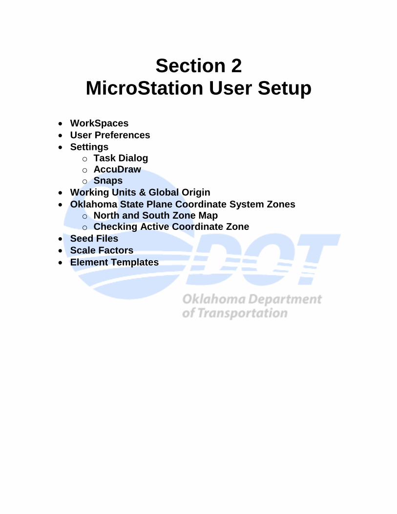
WorkSpaces
User Preferences
Settings o Task Dialog o AccuDraw o Snaps
Working Units & Global Origin
Oklahoma State Plane Coordinate System Zones o North and South Zone Map o Checking Active Coordinate Zone
Seed Files
Scale Factors
Element Templates
WorkSpaces
A workspace is a custom working environment in MicroStation. When you run MicroStation, you enter a workspace. The following components make up a workspace: User - The user configuration file and the user preference file Project - The (optional) project configurations file (and project folders) Interface - The user interface folder (and modification files)
Each workspace component holds information to customize the working environment. The user configuration or UCF file holds configuration variables that are unique to a single user and are not intended to be shared with a group. The user preference or UPF file holds user preference settings. User preference settings include all those settings found in the Preferences dialog box in MicroStation, plus other user specific settings such as file history, tool locations and settings boxes. The Project Configuration (PCF) File and Folders hold standard resource files to be shared by all users working together on a particular project. The project configuration or PCF file holds configuration variables that point to the standards in the project folders. Roadway Design uses a redirect file to maintain this basic configuration. This file points to a master configuration file on the R: Drive. The Master file controls the configuration variables that a standard Roadway user will need. Some of these Include print styles, line styles, dimension styles and text styles. Once MicroStation software is loaded on a machine the xRDYredirect.cfg file should be copied into the following location: C:\ProgramData\Bentley\MicroStation V8i (SELECTseries)\WorkSpace\Standards When MicroStation is launched the first time the following workspace settings should be active. This is the default and should not be changed.
ODOT Roadway Design CADD Manual April 1, 2015
2.1.1
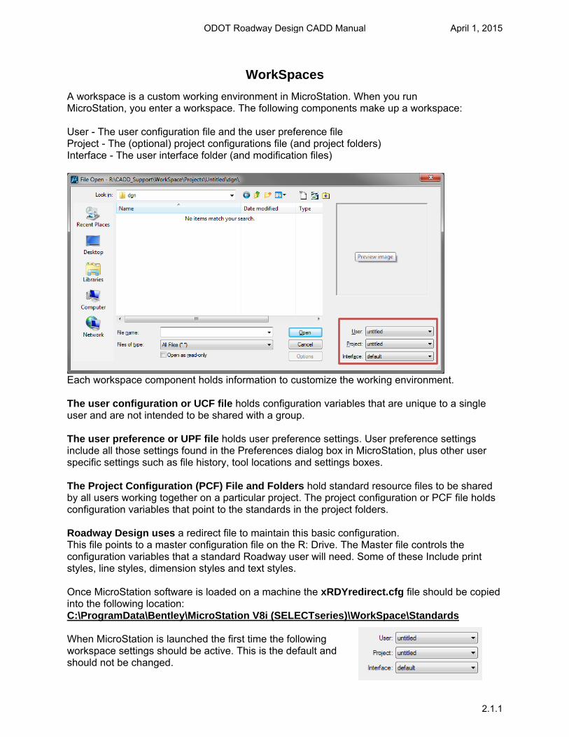
User preferences are settings that control the operation of Microstation. This section covers the most common settings a user will change. Users can adjust these settings to suit personal likes and dislikes without adjusting the settings of other users.
MicroStation User Preferences
ODOT Roadway Design CADD Manual April 1, 2015
2.2.1
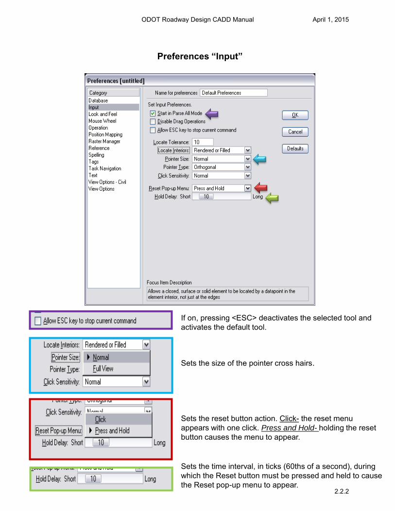
If on, pressing <ESC> deactivates the selected tool and activates the default tool.
Sets the size of the pointer cross hairs.
Sets the reset button action. Click- the reset menu appears with one click. Press and Hold- holding the reset button causes the menu to appear.
Sets the time interval, in ticks (60ths of a second), during which the Reset button must be pressed and held to cause the Reset pop-up menu to appear.
Preferences “Input”
ODOT Roadway Design CADD Manual April 1, 2015
2.2.2

Sets the tool that is automatically selected if <ESC> function is active or upon completion of a one-time function.(Default is Selection)
Sets the size, in pixels, of tool icons
Sets the size, in pixels, of tool icons in toolboxes docked to open view windows. The effect of this setting is visible only while Window > view toolbox is on.
“Preferences Look and Feel”
ODOT Roadway Design CADD Manual April 1, 2015
2.2.3
Preferences “Look and Feel”
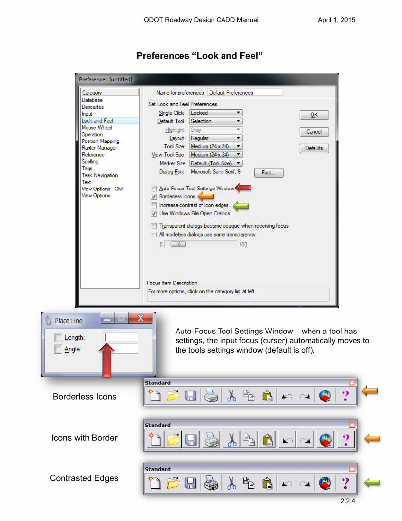
Auto-Focus Tool Settings Window – when a tool has settings, the input focus (curser) automatically moves to the tools settings window (default is off).
Borderless Icons
Icons with Border
Contrasted Edges
ODOT Roadway Design CADD Manual April 1, 2015
2.2.4
Preferences “Look and Feel
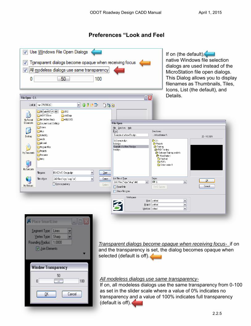
Transparent dialogs become opaque when receiving focus- if on and the transparency is set, the dialog becomes opaque when selected (default is off).
If on (the default), native Windows file selection dialogs are used instead of the MicroStation file open dialogs. This Dialog allows you to display filenames as Thumbnails, Tiles, Icons, List (the default), and Details.
All modeless dialogs use same transparency-
If on, all modeless dialogs use the same transparency from 0-100 as set in the slider scale where a value of 0% indicates no transparency and a value of 100% indicates full transparency (default is off).
ODOT Roadway Design CADD Manual April 1, 2015
2.2.5
Preferences “Operation”
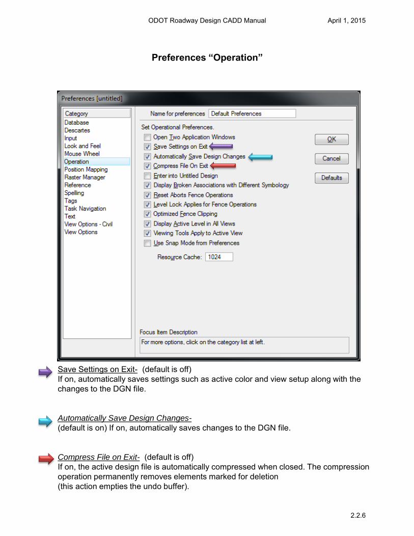
Save Settings on Exit- (default is off) If on, automatically saves settings such as active color and view setup along with the changes to the DGN file.
Automatically Save Design Changes-
(default is on) If on, automatically saves changes to the DGN file. Compress File on Exit- (default is off) If on, the active design file is automatically compressed when closed. The compression operation permanently removes elements marked for deletion (this action empties the undo buffer).
ODOT Roadway Design CADD Manual April 1, 2015
2.2.6
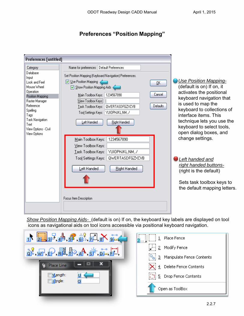
Preferences “Position Mapping”
Use Position Mapping-
(default is on) If on, it activates the positional keyboard navigation that is used to map the keyboard to collections of interface items. This technique lets you use the keyboard to select tools, open dialog boxes, and change settings.
Left handed and
right handed buttons- (right is the default)
Sets task toolbox keys to the default mapping letters.
Show Position Mapping Aids- (default is on) If on, the keyboard key labels are displayed on tool icons as navigational aids on tool icons accessible via positional keyboard navigation.
ODOT Roadway Design CADD Manual April 1, 2015
2.2.7
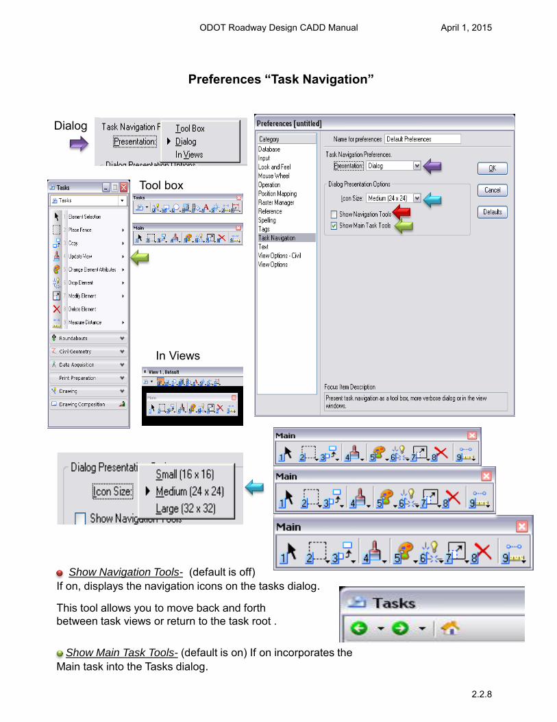
Preferences “Task Navigation”
Tool box
Dialog
In Views
Show Navigation Tools- (default is off) If on, displays the navigation icons on the tasks dialog.
Show Main Task Tools- (default is on) If on incorporates the Main task into the Tasks dialog.
This tool allows you to move back and forth between task views or return to the task root .
ODOT Roadway Design CADD Manual April 1, 2015
2.2.8
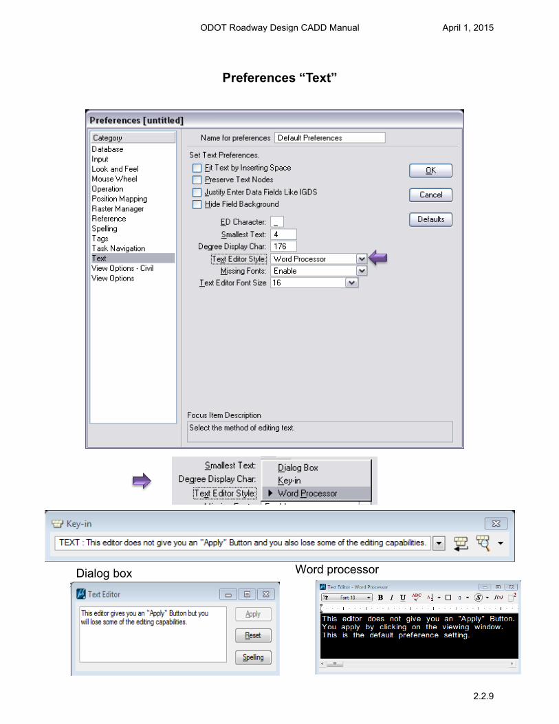
Preferences “Text”
Dialog box Word processor
ODOT Roadway Design CADD Manual April 1, 2015
2.2.9
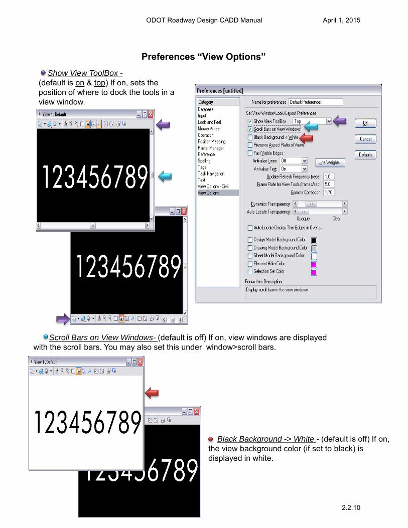
Preferences “View Options”
Show View ToolBox -
(default is on & top) If on, sets the position of where to dock the tools in a view window.
Scroll Bars on View Windows- (default is off) If on, view windows are displayed with the scroll bars. You may also set this under window>scroll bars.
Black Background -> White - (default is off) If on, the view background color (if set to black) is displayed in white.
ODOT Roadway Design CADD Manual April 1, 2015
2.2.10
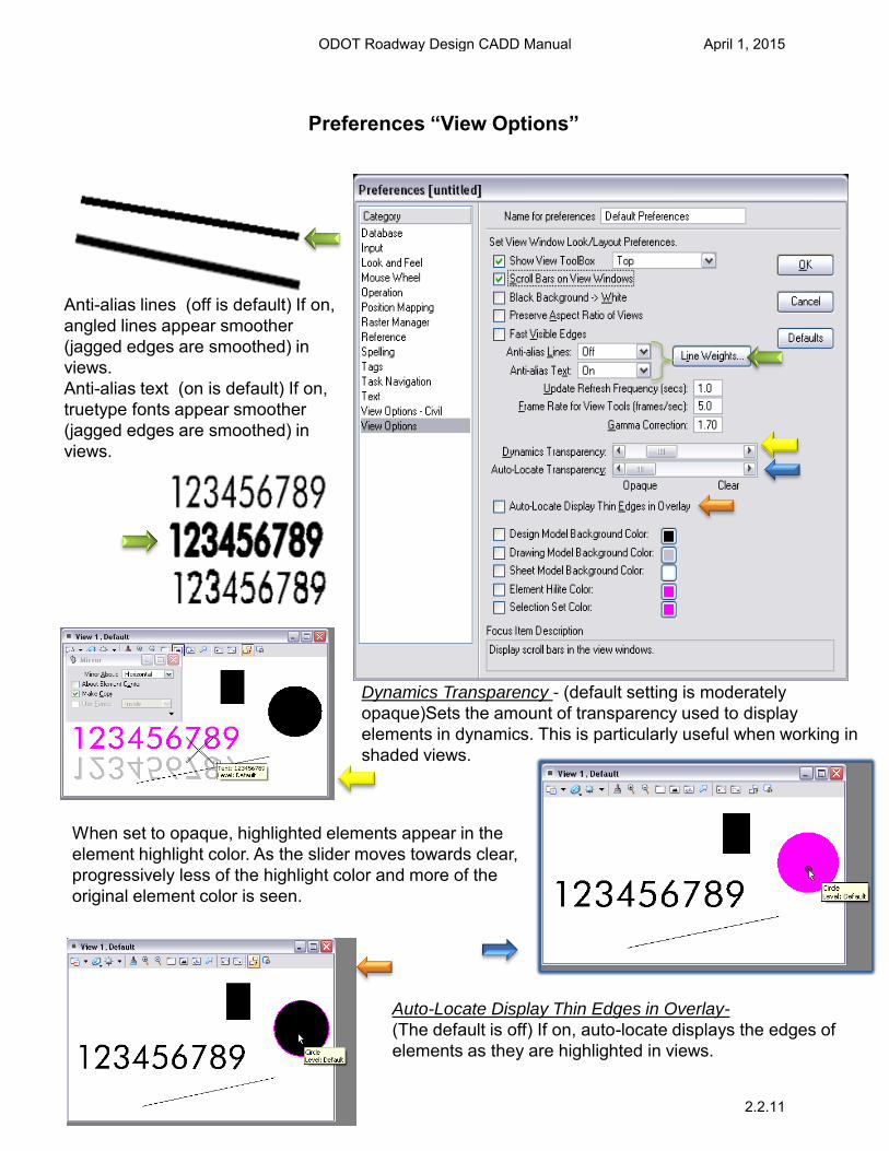
Anti-alias lines (off is default) If on, angled lines appear smoother (jagged edges are smoothed) in views. Anti-alias text (on is default) If on, truetype fonts appear smoother (jagged edges are smoothed) in views.
Dynamics Transparency - (default setting is moderately opaque)Sets the amount of transparency used to display elements in dynamics. This is particularly useful when working in shaded views.
When set to opaque, highlighted elements appear in the element highlight color. As the slider moves towards clear, progressively less of the highlight color and more of the original element color is seen.
Auto-Locate Display Thin Edges in Overlay- (The default is off) If on, auto-locate displays the edges of elements as they are highlighted in views.
Preferences “View Options”
ODOT Roadway Design CADD Manual April 1, 2015
2.2.11
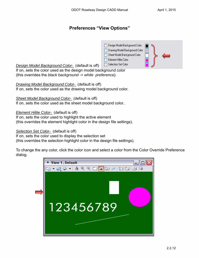
Preferences “View Options”
Design Model Background Color- (default is off) If on, sets the color used as the design model background color (this overrides the black background -> white preference). Drawing Model Background Color- (default is off) If on, sets the color used as the drawing model background color. Sheet Model Background Color- (default is off) If on, sets the color used as the sheet model background color.. Element Hilite Color- (default is off) If on, sets the color used to highlight the active element (this overrides the element highlight color in the design file settings). Selection Set Color- (default is off) If on, sets the color used to display the selection set (this overrides the selection highlight color in the design file settings). To change the any color, click the color icon and select a color from the Color Override Preference dialog.
ODOT Roadway Design CADD Manual April 1, 2015
2.2.12
Settings “Task Dialog”
A Task is a set of tools grouped to
facilitate a particular workflow.
By defining and grouping tasks, you can
create a task-based interface.
The tools grouped into a given task can be
standard MicroStation tools, custom tools,
or a mixture of both types.
Tasks contain references to tools, tool
boxes, and tool frames, and can therefore
contain overlapping sets of tools.
For example: a user-defined Drafting task
and Drawing Composition task likely
would both contain the text tools.
ODOT Roadway Design CADD Manual April 1, 2015
2.3.1

The task dialog can be accessed under tools>tasks
The Task Navigation default preference for presentation is dialog.
Click the down arrow in the task dialog to access the drawing tools. The Main And Drawing Tools Cover Most Of The Commands Commonly Used.
Settings “Task Dialog”
ODOT Roadway Design CADD Manual April 1, 2015
2.3.2
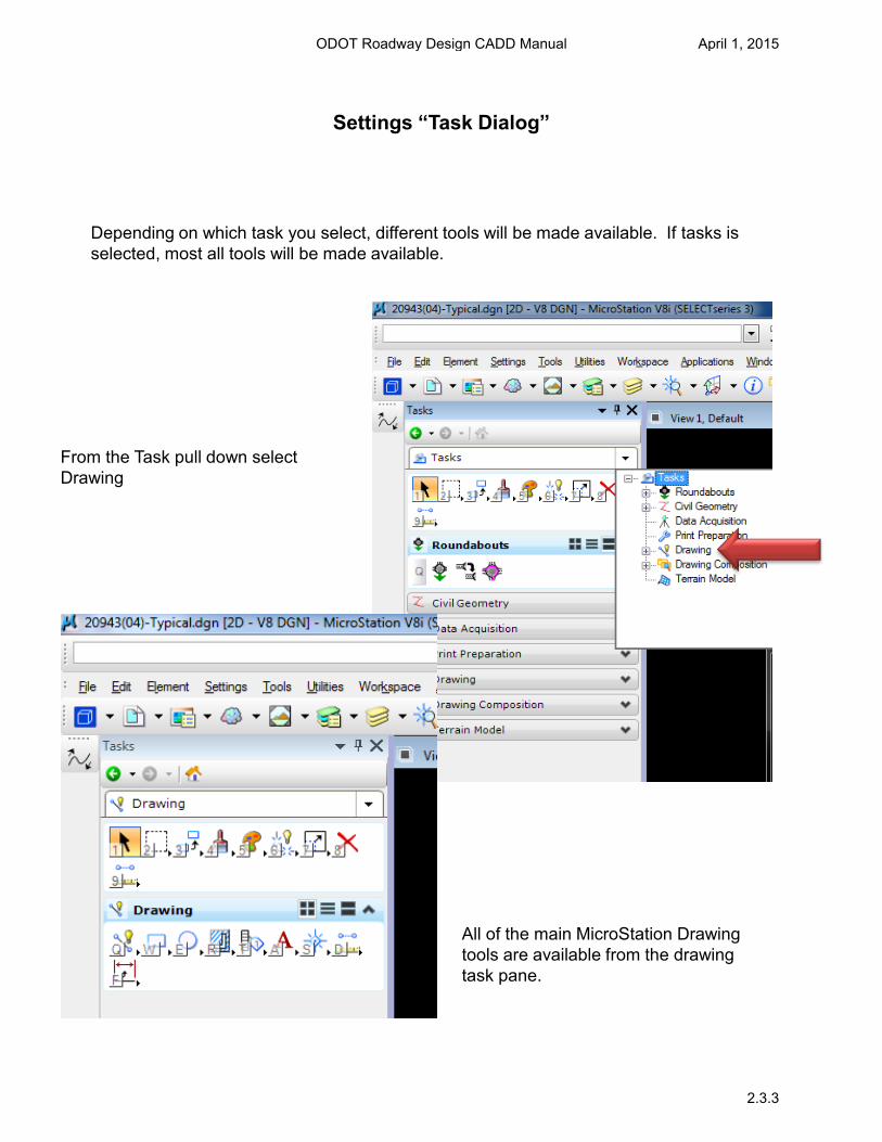
Depending on which task you select, different tools will be made available. If tasks is selected, most all tools will be made available.
From the Task pull down select Drawing
All of the main MicroStation Drawing tools are available from the drawing task pane.
Settings “Task Dialog”
ODOT Roadway Design CADD Manual April 1, 2015
2.3.3
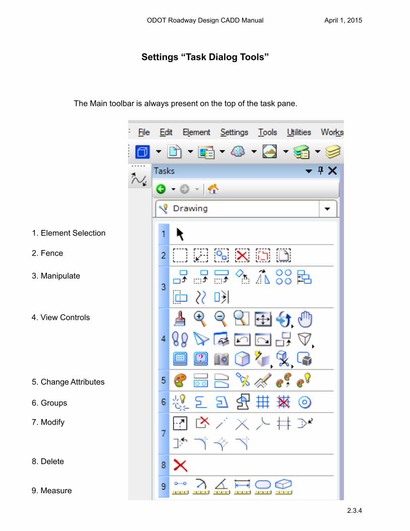
5. Change Attributes
6. Groups
9. Measure
7. Modify
8. Delete
Settings “Task Dialog Tools”
2. Fence
3. Manipulate
4. View Controls
The Main toolbar is always present on the top of the task pane.
1. Element Selection
ODOT Roadway Design CADD Manual April 1, 2015
2.3.4
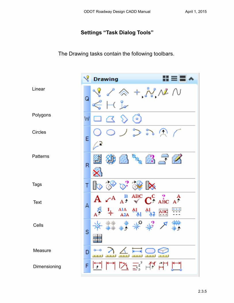
Linear
Polygons
Circles
Patterns
Tags
Text
Cells
The Drawing tasks contain the following toolbars.
Measure
Dimensioning
Settings “Task Dialog Tools”
ODOT Roadway Design CADD Manual April 1, 2015
2.3.5
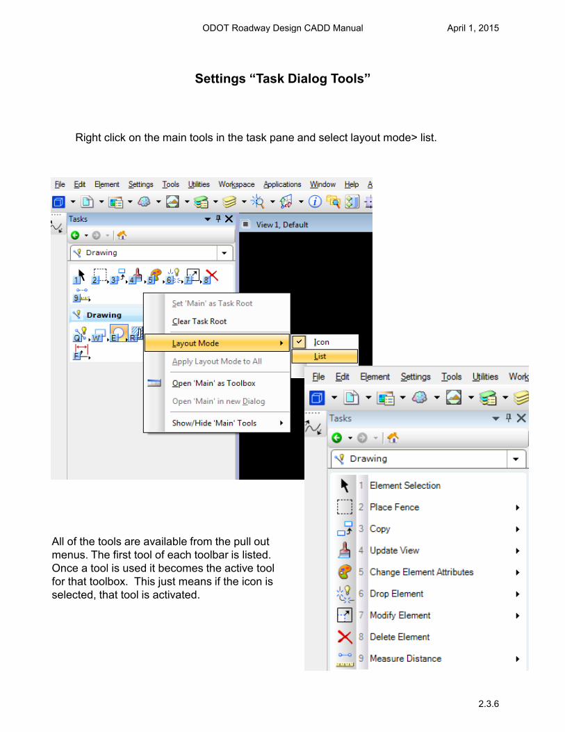
All of the tools are available from the pull out menus. The first tool of each toolbar is listed. Once a tool is used it becomes the active tool for that toolbox. This just means if the icon is selected, that tool is activated.
Right click on the main tools in the task pane and select layout mode> list.
Settings “Task Dialog Tools”
ODOT Roadway Design CADD Manual April 1, 2015
2.3.6
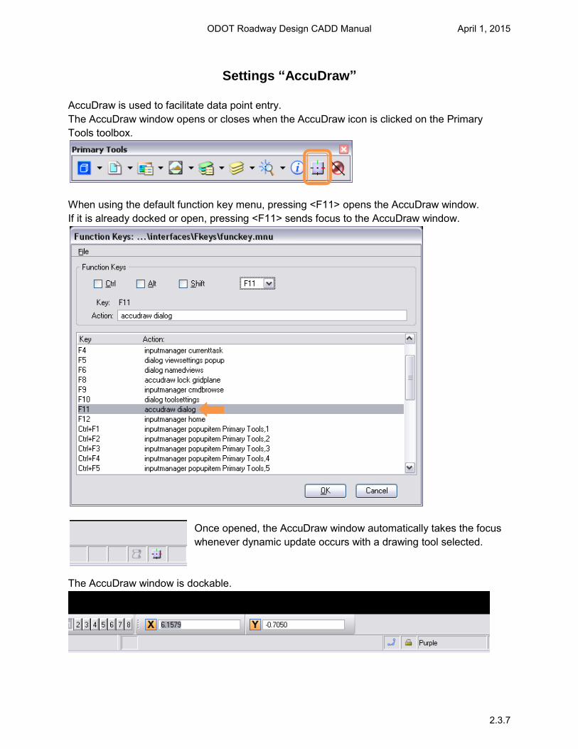
Settings “AccuDraw” AccuDraw is used to facilitate data point entry. The AccuDraw window opens or closes when the AccuDraw icon is clicked on the Primary Tools toolbox.
When using the default function key menu, pressing <F11> opens the AccuDraw window. If it is already docked or open, pressing <F11> sends focus to the AccuDraw window.
Once opened, the AccuDraw window automatically takes the focus whenever dynamic update occurs with a drawing tool selected.
The AccuDraw window is dockable.
ODOT Roadway Design CADD Manual April 1, 2015
2.3.7
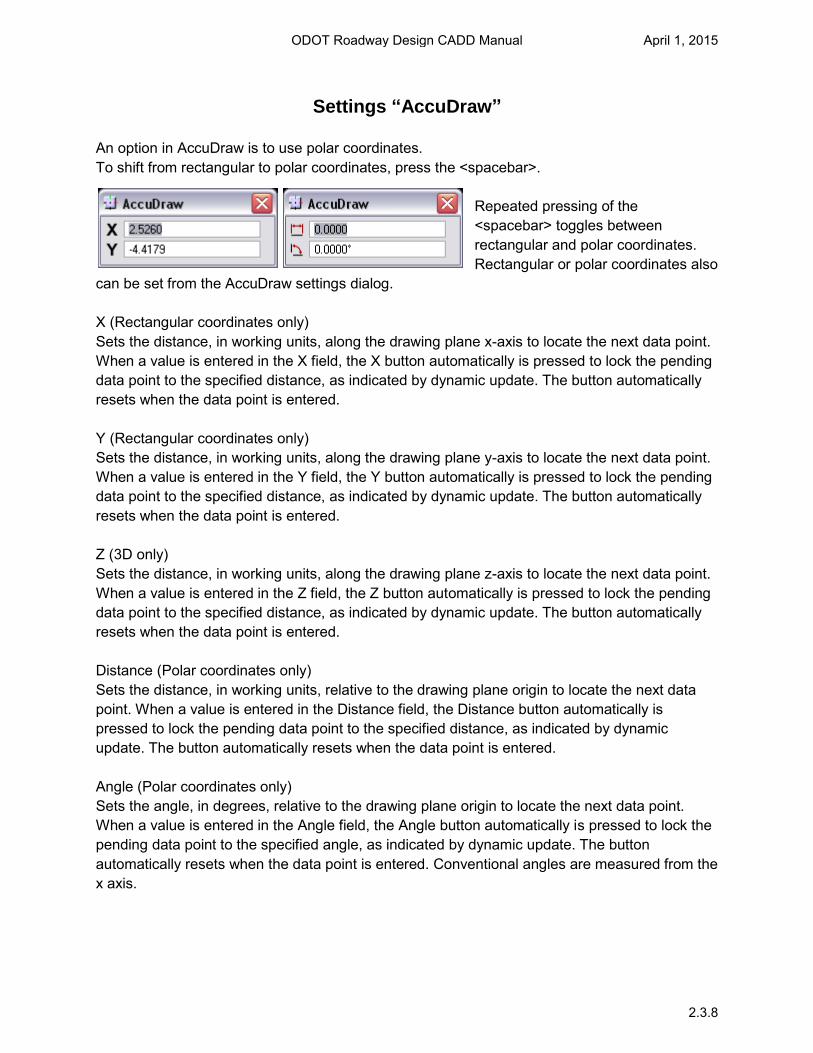
Settings “AccuDraw” An option in AccuDraw is to use polar coordinates. To shift from rectangular to polar coordinates, press the <spacebar>.
Repeated pressing of the <spacebar> toggles between rectangular and polar coordinates. Rectangular or polar coordinates also
can be set from the AccuDraw settings dialog. X (Rectangular coordinates only) Sets the distance, in working units, along the drawing plane x-axis to locate the next data point. When a value is entered in the X field, the X button automatically is pressed to lock the pending data point to the specified distance, as indicated by dynamic update. The button automatically resets when the data point is entered. Y (Rectangular coordinates only) Sets the distance, in working units, along the drawing plane y-axis to locate the next data point. When a value is entered in the Y field, the Y button automatically is pressed to lock the pending data point to the specified distance, as indicated by dynamic update. The button automatically resets when the data point is entered. Z (3D only) Sets the distance, in working units, along the drawing plane z-axis to locate the next data point. When a value is entered in the Z field, the Z button automatically is pressed to lock the pending data point to the specified distance, as indicated by dynamic update. The button automatically resets when the data point is entered. Distance (Polar coordinates only) Sets the distance, in working units, relative to the drawing plane origin to locate the next data point. When a value is entered in the Distance field, the Distance button automatically is pressed to lock the pending data point to the specified distance, as indicated by dynamic update. The button automatically resets when the data point is entered. Angle (Polar coordinates only) Sets the angle, in degrees, relative to the drawing plane origin to locate the next data point. When a value is entered in the Angle field, the Angle button automatically is pressed to lock the pending data point to the specified angle, as indicated by dynamic update. The button automatically resets when the data point is entered. Conventional angles are measured from the x axis.
ODOT Roadway Design CADD Manual April 1, 2015
2.3.8
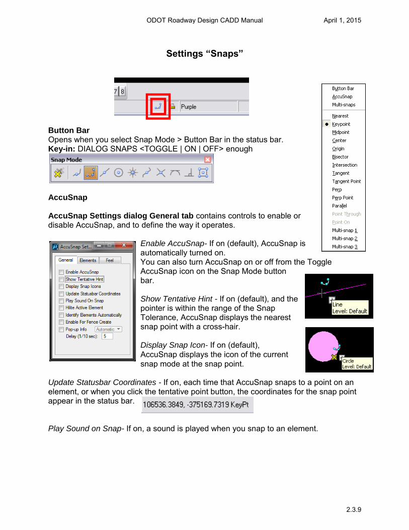
Settings “Snaps”
Button Bar Opens when you select Snap Mode > Button Bar in the status bar. Key-in: DIALOG SNAPS <TOGGLE | ON | OFF> enough
AccuSnap
AccuSnap Settings dialog General tab contains controls to enable or disable AccuSnap, and to define the way it operates.
Enable AccuSnap- If on (default), AccuSnap is automatically turned on. You can also turn AccuSnap on or off from the Toggle AccuSnap icon on the Snap Mode button bar.
Show Tentative Hint - If on (default), and the pointer is within the range of the Snap Tolerance, AccuSnap displays the nearest snap point with a cross-hair.
Display Snap Icon- If on (default), AccuSnap displays the icon of the current snap mode at the snap point.
Update Statusbar Coordinates - If on, each time that AccuSnap snaps to a point on an element, or when you click the tentative point button, the coordinates for the snap point appear in the status bar.
Play Sound on Snap- If on, a sound is played when you snap to an element.
ODOT Roadway Design CADD Manual April 1, 2015
2.3.9
Settings “Snaps”
Hilite Active Element- If on, the active element highlights as soon as the pointer is within the range of the Snap Tolerance. If off, the active element highlights only when a tentative snap point is displayed.
Identify Elements Automatically- If on, elements are identified automatically, as you pass the pointer over them.
Enable For Fence Create- If on, AccuSnap is active when placing a fence.
Pop-up Info- If on, and you pause the pointer over a highlighted element, a pop-up displays information about the element. An option menu lets you define when this information appears.
(Automatic) Pop-up information appears whenever you pause the pointer over a highlighted element. (Tentative) Pop-up information appears only when you manually snap a tentative point to an element and then hold the pointer over any part of the highlighted element.
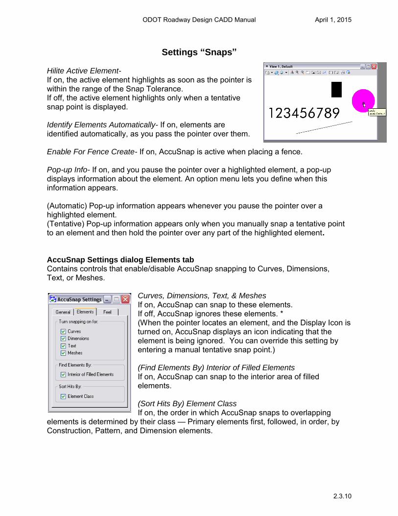
AccuSnap Settings dialog Elements tab Contains controls that enable/disable AccuSnap snapping to Curves, Dimensions, Text, or Meshes.
Curves, Dimensions, Text, & MeshesIf on, AccuSnap can snap to these elements. If off, AccuSnap ignores these elements. * (When the pointer locates an element, and the Display Icon is turned on, AccuSnap displays an icon indicating that the element is being ignored. You can override this setting by entering a manual tentative snap point.)
(Find Elements By) Interior of Filled Elements If on, AccuSnap can snap to the interior area of filled elements.
(Sort Hits By) Element Class If on, the order in which AccuSnap snaps to overlapping
elements is determined by their class — Primary elements first, followed, in order, by Construction, Pattern, and Dimension elements.
ODOT Roadway Design CADD Manual April 1, 2015
2.3.10
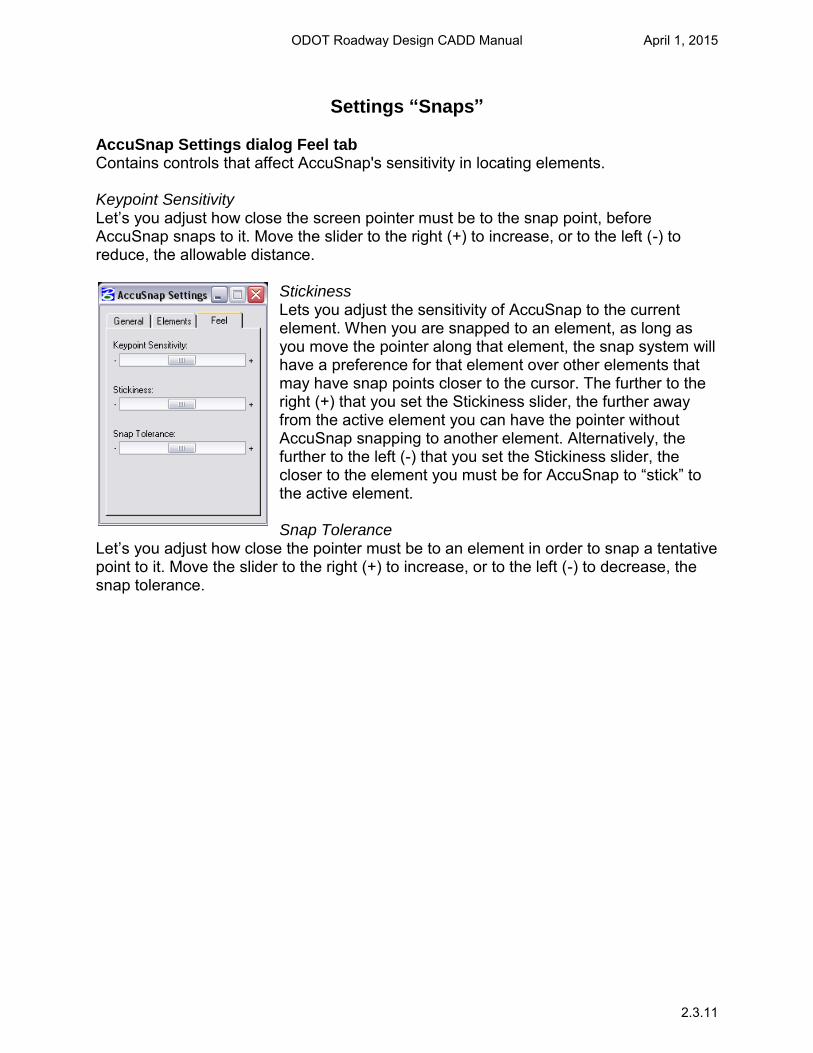
Settings “Snaps” AccuSnap Settings dialog Feel tab Contains controls that affect AccuSnap's sensitivity in locating elements. Keypoint Sensitivity Let’s you adjust how close the screen pointer must be to the snap point, before AccuSnap snaps to it. Move the slider to the right (+) to increase, or to the left (-) to reduce, the allowable distance.
Stickiness Lets you adjust the sensitivity of AccuSnap to the current element. When you are snapped to an element, as long as you move the pointer along that element, the snap system will have a preference for that element over other elements that may have snap points closer to the cursor. The further to the right (+) that you set the Stickiness slider, the further away from the active element you can have the pointer without AccuSnap snapping to another element. Alternatively, the further to the left (-) that you set the Stickiness slider, the closer to the element you must be for AccuSnap to “stick” to the active element. Snap Tolerance
Let’s you adjust how close the pointer must be to an element in order to snap a tentative point to it. Move the slider to the right (+) to increase, or to the left (-) to decrease, the snap tolerance.
ODOT Roadway Design CADD Manual April 1, 2015
2.3.11
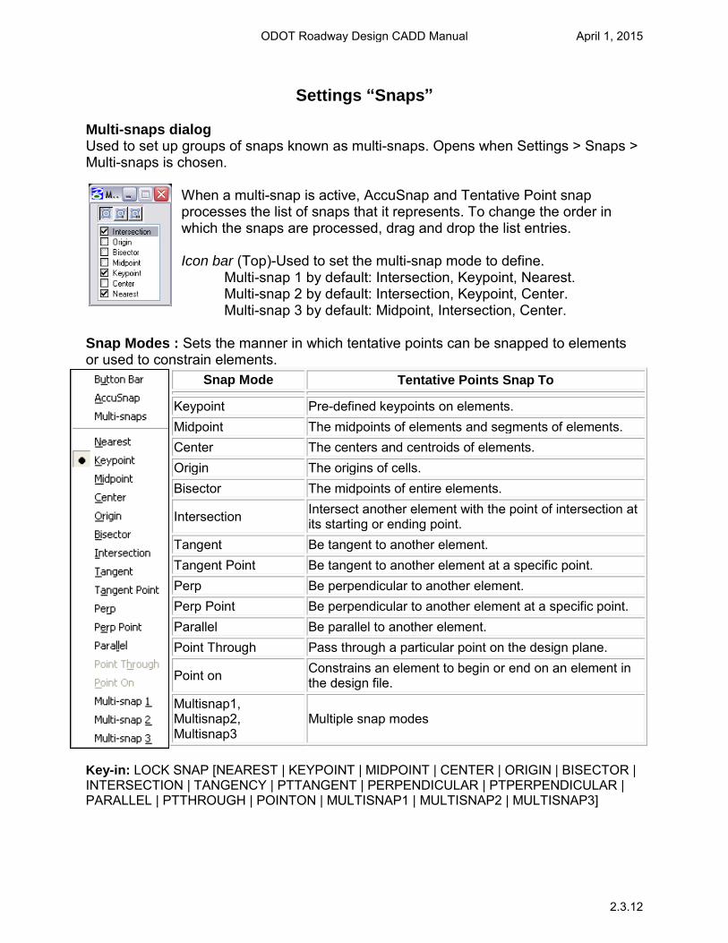
Settings “Snaps” Multi-snaps dialog Used to set up groups of snaps known as multi-snaps. Opens when Settings > Snaps > Multi-snaps is chosen.
When a multi-snap is active, AccuSnap and Tentative Point snap processes the list of snaps that it represents. To change the order in which the snaps are processed, drag and drop the list entries. Icon bar (Top)-Used to set the multi-snap mode to define.
Multi-snap 1 by default: Intersection, Keypoint, Nearest. Multi-snap 2 by default: Intersection, Keypoint, Center. Multi-snap 3 by default: Midpoint, Intersection, Center.
Snap Modes : Sets the manner in which tentative points can be snapped to elements or used to constrain elements.
Snap Mode Tentative Points Snap To
Keypoint Pre-defined keypoints on elements. Midpoint The midpoints of elements and segments of elements. Center The centers and centroids of elements. Origin The origins of cells. Bisector The midpoints of entire elements.
Intersection Intersect another element with the point of intersection at its starting or ending point.
Tangent Be tangent to another element. Tangent Point Be tangent to another element at a specific point. Perp Be perpendicular to another element. Perp Point Be perpendicular to another element at a specific point. Parallel Be parallel to another element. Point Through Pass through a particular point on the design plane.
Point on Constrains an element to begin or end on an element in the design file.
Multisnap1, Multisnap2, Multisnap3
Multiple snap modes
Key-in: LOCK SNAP [NEAREST | KEYPOINT | MIDPOINT | CENTER | ORIGIN | BISECTOR | INTERSECTION | TANGENCY | PTTANGENT | PERPENDICULAR | PTPERPENDICULAR | PARALLEL | PTTHROUGH | POINTON | MULTISNAP1 | MULTISNAP2 | MULTISNAP3]
ODOT Roadway Design CADD Manual April 1, 2015
2.3.12

Working Units and Global Origin
Note: The working units and global origin have already been set in the Roadway Design Seed Files. Using a preset seed file eliminates having to setup the working units in the drawing files. English (Imperial):
Master Units: US Survey Feet* Sub Units: US Survey Inches Resolution: 1200 per Distance US Survey Foot Working Area: 1421593635 Square Miles (X and Y Axis) 677.868669 Miles (Z Axis) Global Origin: Lower Left 2d => GO = 0.0000, 0.0000 3d => GO = 0.0000, 0.0000, 0.0000 * One International foot equals 0.999998 U.S. Survey feet. OR One U.S. Survey foot equals 1.000002 International feet. It might not seem like much, but over a distance of miles this will add up and will cause points and elements to be in the wrong location. Metric:
Master Units: Meters Sub Units: Centimeters Resolution: 1200 per Distance Foot Working Area: 1421590791 Square Miles (X and Y Axis) 677.867313 Miles (Z Axis) Global Origin: Lower Left 2d => GO = 0.0000, 0.0000 3d => GO = 0.0000, 0.0000, 0.0000
ODOT Roadway Design CADD Manual April 1, 2015
2.4.1
Oklahoma State Plane Coordinate System Zones
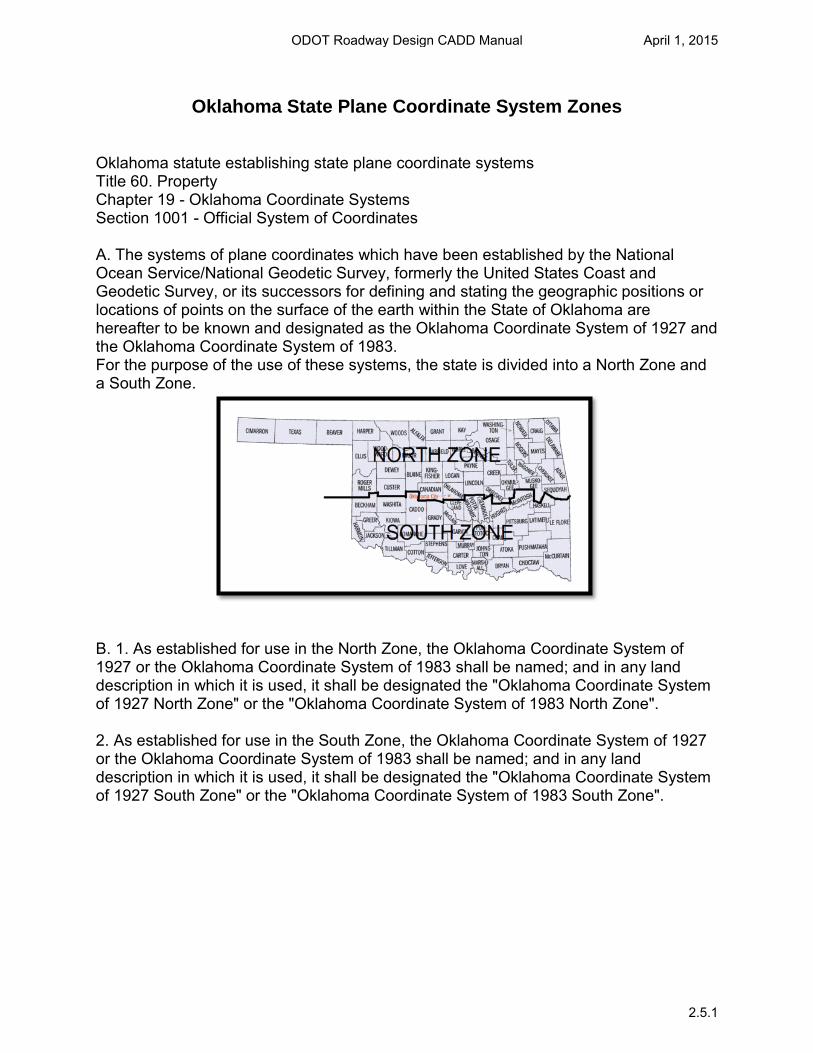
Oklahoma statute establishing state plane coordinate systems Title 60. Property Chapter 19 - Oklahoma Coordinate Systems Section 1001 - Official System of Coordinates A. The systems of plane coordinates which have been established by the National Ocean Service/National Geodetic Survey, formerly the United States Coast and Geodetic Survey, or its successors for defining and stating the geographic positions or locations of points on the surface of the earth within the State of Oklahoma are hereafter to be known and designated as the Oklahoma Coordinate System of 1927 and the Oklahoma Coordinate System of 1983. For the purpose of the use of these systems, the state is divided into a North Zone and a South Zone.
B. 1. As established for use in the North Zone, the Oklahoma Coordinate System of 1927 or the Oklahoma Coordinate System of 1983 shall be named; and in any land description in which it is used, it shall be designated the "Oklahoma Coordinate System of 1927 North Zone" or the "Oklahoma Coordinate System of 1983 North Zone". 2. As established for use in the South Zone, the Oklahoma Coordinate System of 1927 or the Oklahoma Coordinate System of 1983 shall be named; and in any land description in which it is used, it shall be designated the "Oklahoma Coordinate System of 1927 South Zone" or the "Oklahoma Coordinate System of 1983 South Zone".
ODOT Roadway Design CADD Manual April 1, 2015
2.5.1
SOUTH ZONE
NORTH ZONE
6763
21
13 70 4 30 76
77
23
47
2 27
24
36
52
22
65 20
6 37
9 55
42
41
60
59
57 7453
66
7219
18 58
49
73 111
68
5156
46
31
4039
6132
54
14
44
45
64
12
3
15
6225
3550
748
10
4334
69
26
8
16
1771
38
33
755
28
29
#
26
25
24
23
22
21
20
19
18
17
16
15
14
13
12
11
10
9
8
7
6
5
4
3
2
1
#
52
51
50
49
48
47
46
45
44
43
42
41
40
39
38
37
36
35
34
33
32
31
30
29
28
27
#
77
76
75
74
73
72
71
70
69
68
67
66
65
64
63
62
61
60
59
58
57
56
55
54
53
GRADY
GARVIN
GARFIELD
ELLIS
DEWEY
DELAWARE
CUSTER
CREEK
CRAIG
COTTON
COMANCHE
COAL
CLEVELAND
CIMARRON
CHOCTAW
CHEROKEE
CARTER
CANADIAN
CADDO
BRYAN
BLAINE
BECKHAM
BEAVER
ATOKA
ALFALFA
ADAIR
7
3
4
6
5
8
5
8
8
7
7
3
3
6
2
1
7
4
7
2
5
5
6
2
6
1
SOUTH
SOUTH
NORTH
NORTH
NORTH
NORTH
NORTH
NORTH
NORTH
SOUTH
SOUTH
SOUTH
SOUTH
NORTH
SOUTH
NORTH
SOUTH
NORTH
SOUTH
SOUTH
NORTH
SOUTH
NORTH
SOUTH
NORTH
NORTH
NOBLE
MUSKOGEE
MURRAY
MCINTOSH
MCCURTAIN
MCCLAIN
MAYES
MARSHALL
MAJOR
LOVE
LOGAN
LINCOLN
LE FLORE
LATIMER
KIOWA
KINGFISHER
KAY
JOHNSTON
JEFFERSON
JACKSON
HUGHES
HASKELL
HARPER
HARMON
GREER
GRANT
4
1
7
8
2
6
1
2
3
7
4
3
2
2
5
4
4
3
7
5
3
1
6
5
5
4
NORTH
NORTH
SOUTH
SOUTH
SOUTH
SOUTH
NORTH
SOUTH
NORTH
SOUTH
NORTH
NORTH
SOUTH
SOUTH
SOUTH
NORTH
NORTH
SOUTH
SOUTH
SOUTH
SOUTH
SOUTH
NORTH
SOUTH
SOUTH
NORTH
NORTH
NORTH
SOUTH
NORTH
NORTH
NORTH
SOUTH
NORTH
SOUTH
NORTH
SOUTH
NORTH
NORTH
SOUTH
SOUTH
SOUTH
SOUTH
NORTH
NORTH
NORTH
NORTH
NORTH
NORTH
NORTH
NORTH
6
6
5
8
1
8
5
6
7
1
3
8
5
2
3
3
2
4
8
8
8
1
4
3
8
WOODWARD
WOODS
WASHITA
WASHINGTON
WAGONER
TULSA
TILLMAN
TEXAS
STEPHENS
SEQUOYAH
SEMINOLE
ROGERS
ROGER MILLS
PUSHMATAHA
POTTAWATOMIE
PONTOTOC
PITTSBURG
PAYNE
PAWNEE
OTTAWA
OSAGE
OKMULGEE
OKLAHOMA
OKFUSKEE
NOWATA
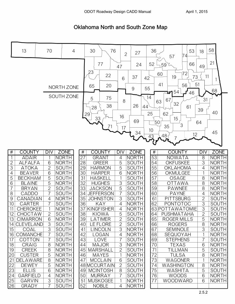
Oklahoma North and South Zone Map
COUNTY DIV ZONE COUNTY DIV ZONE COUNTY DIV ZONE
ODOT Roadway Design CADD Manual April 1, 2015
2.5.2
Checking Active Coordinate Zone
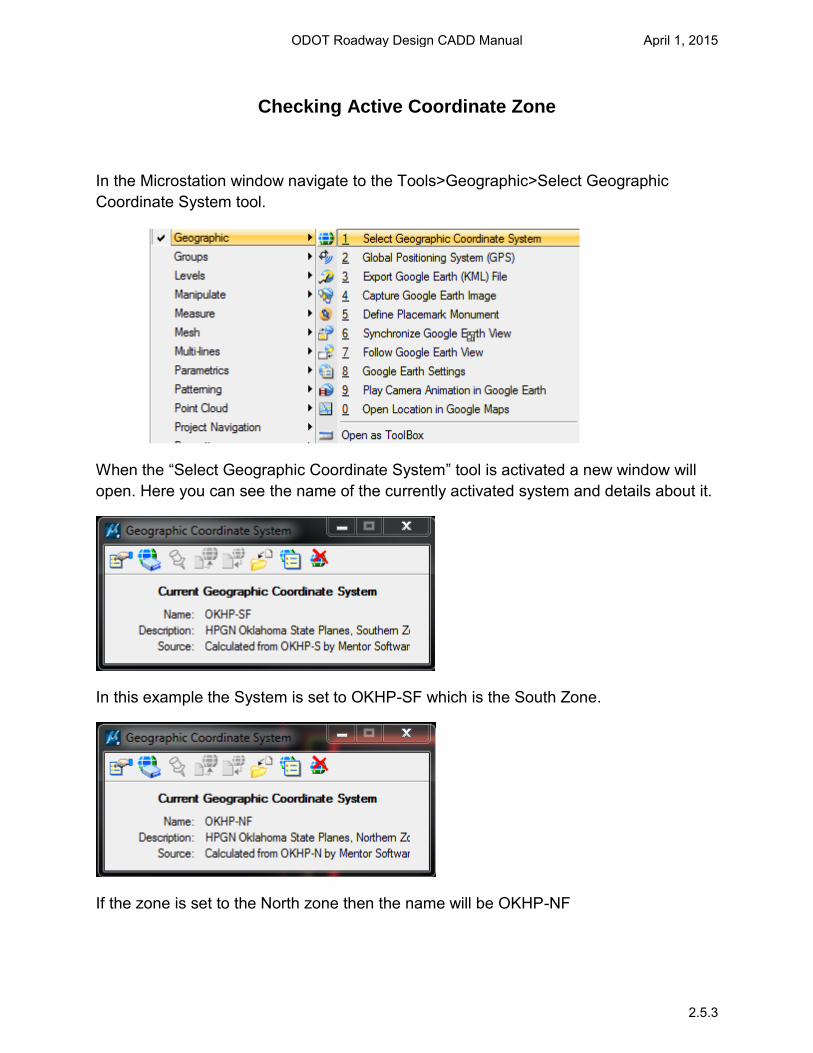
In the Microstation window navigate to the Tools>Geographic>Select Geographic Coordinate System tool.
When the “Select Geographic Coordinate System” tool is activated a new window will open. Here you can see the name of the currently activated system and details about it.
In this example the System is set to OKHP-SF which is the South Zone.
If the zone is set to the North zone then the name will be OKHP-NF
ODOT Roadway Design CADD Manual April 1, 2015
2.5.3
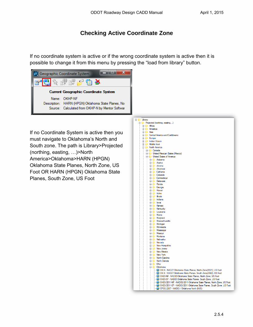
Checking Active Coordinate Zone
If no coordinate system is active or if the wrong coordinate system is active then it is possible to change it from this menu by pressing the “load from library” button.
If no Coordinate System is active then you must navigate to Oklahoma’s North and
South zone. The path is Library>Projected (northing, easting, …)>North
America>Oklahoma>HARN (HPGN) Oklahoma State Planes, North Zone, US Foot OR HARN (HPGN) Oklahoma State Planes, South Zone, US Foot
ODOT Roadway Design CADD Manual April 1, 2015
2.5.4
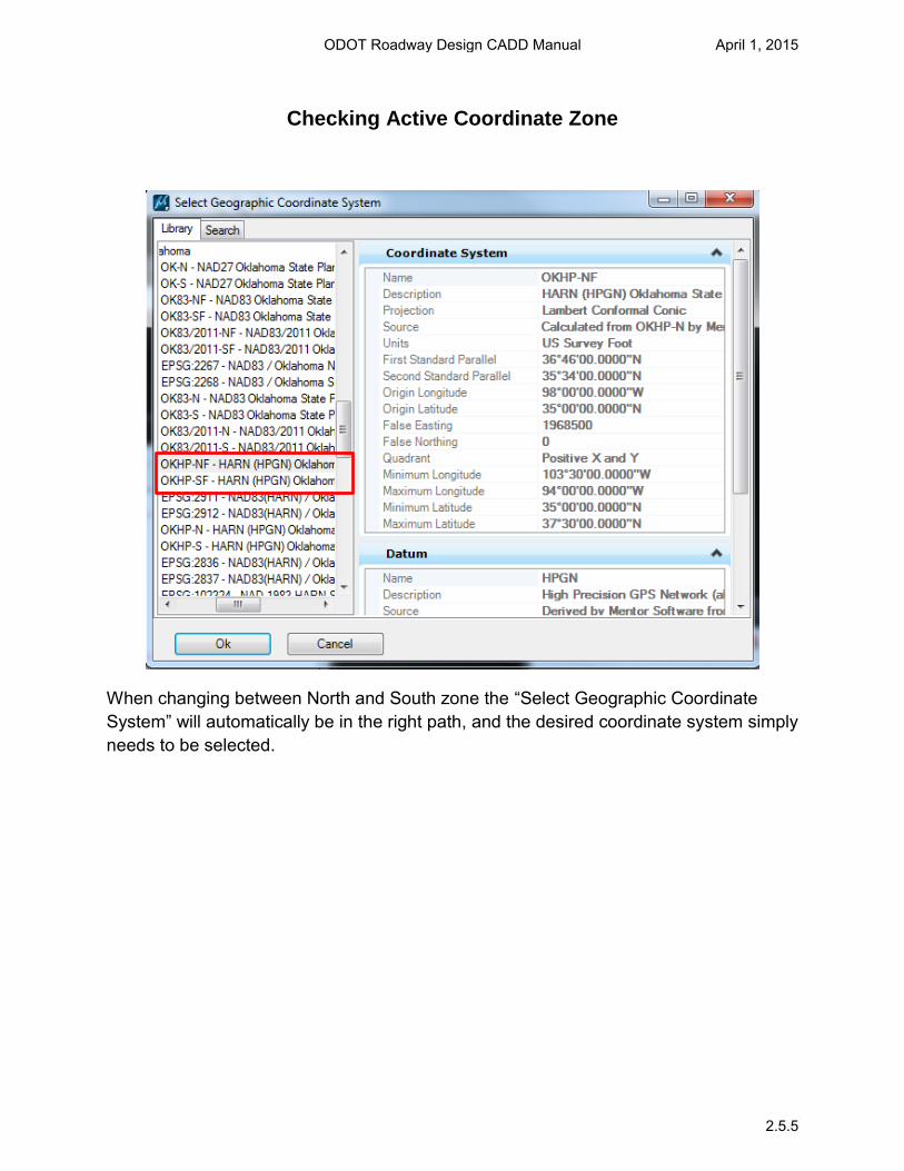
Checking Active Coordinate Zone
When changing between North and South zone the “Select Geographic Coordinate System” will automatically be in the right path, and the desired coordinate system simply needs to be selected.
ODOT Roadway Design CADD Manual April 1, 2015
2.5.5

Seed Files
A seed file is a MicroStation template used to create new design files. When using the File/New option, MicroStation generates a new file with the same content and settings as the original template. Seed files standardize and automate the design file creation process. Every new file will have the same models, elements, cell libraries, view groups, saved views, working units, color table, ACS location, global origin, geographic coordinate system and 2D or 3D environment as the seed file selected.
Roadway Designs Seed File Location: R:\CADD_Support\MicroStation\Seed Files\Roadway\(select the ZONE)North (or) South Roadway Designs seed files are also available at: http://www.okladot.state.ok.us/roadway/CADD_Support/MicroStation/Seed_Files/
ODOT Roadway Design CADD Manual April 1, 2015
2.6.1
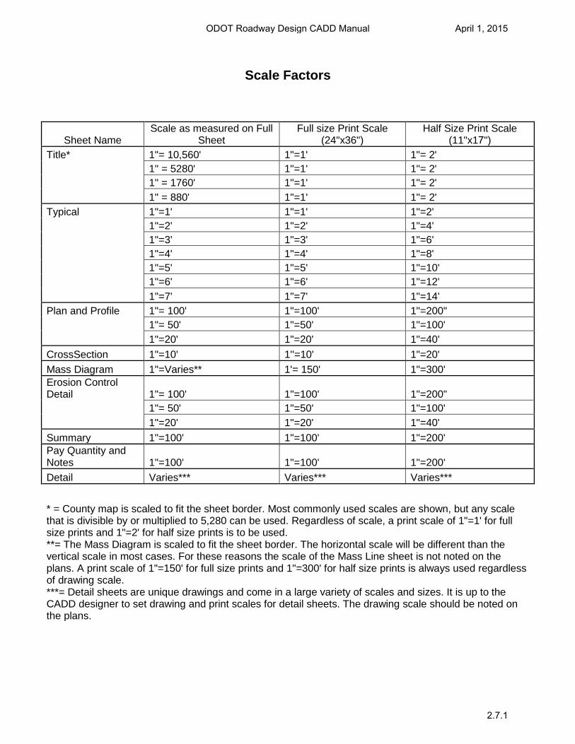
Scale Factors
Sheet Name Scale as measured on Full
Sheet Full size Print Scale
(24"x36") Half Size Print Scale
(11"x17")
Title* 1"= 10,560' 1"=1' 1"= 2' 1" = 5280' 1"=1' 1"= 2' 1" = 1760' 1"=1' 1"= 2'
1" = 880' 1"=1' 1"= 2'
Typical 1"=1' 1"=1' 1"=2' 1"=2' 1"=2' 1"=4' 1"=3' 1"=3' 1"=6' 1"=4' 1"=4' 1"=8' 1"=5' 1"=5' 1"=10' 1"=6' 1"=6' 1"=12'
1"=7' 1"=7' 1"=14' Plan and Profile 1"= 100' 1"=100' 1"=200"
1"= 50' 1"=50' 1"=100'
1"=20' 1"=20' 1"=40'
CrossSection 1"=10' 1''=10' 1"=20'
Mass Diagram 1"=Varies** 1'= 150' 1"=300' Erosion Control Detail 1"= 100' 1"=100' 1"=200"
1"= 50' 1"=50' 1"=100'
1"=20' 1"=20' 1"=40'
Summary 1"=100' 1"=100' 1"=200' Pay Quantity and Notes 1"=100' 1"=100' 1"=200'
Detail Varies*** Varies*** Varies***
* = County map is scaled to fit the sheet border. Most commonly used scales are shown, but any scalethat is divisible by or multiplied to 5,280 can be used. Regardless of scale, a print scale of 1"=1' for full size prints and 1"=2' for half size prints is to be used. **= The Mass Diagram is scaled to fit the sheet border. The horizontal scale will be different than the vertical scale in most cases. For these reasons the scale of the Mass Line sheet is not noted on the plans. A print scale of 1"=150' for full size prints and 1"=300' for half size prints is always used regardless of drawing scale. ***= Detail sheets are unique drawings and come in a large variety of scales and sizes. It is up to the CADD designer to set drawing and print scales for detail sheets. The drawing scale should be noted on the plans.
ODOT Roadway Design CADD Manual April 1, 2015
2.7.1
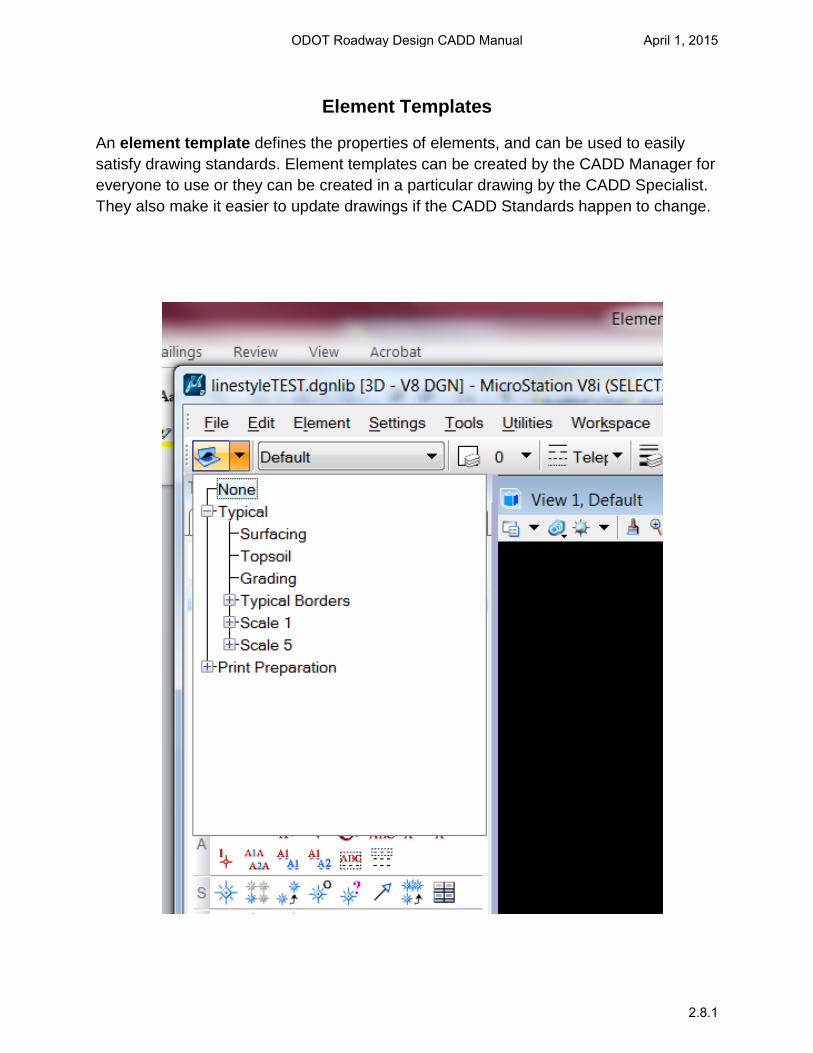
Element Templates
An element template defines the properties of elements, and can be used to easily satisfy drawing standards. Element templates can be created by the CADD Manager for everyone to use or they can be created in a particular drawing by the CADD Specialist. They also make it easier to update drawings if the CADD Standards happen to change.
ODOT Roadway Design CADD Manual April 1, 2015
2.8.1