Recent developments and perspectives around ISO 15926 By ...
Building Automation SystemMaster Specification
Division 15 (15950)
SECTION 15950 - HVAC CONTROLS
PART 1 - GENERAL
1.1 DESCRIPTION
This section defines the Basic Materials and Methods used in the installation of LonWorks Control products to provide the functions necessary for control of the mechanical systems on this project. Please be advised that the requirements of this specification will be strictly enforced. Specifically, systems that do not meet the requirements of the specification as outlined below, specifically section 1.1 of this specification, shall not be accepted.
A. Provide a Facility Management and Control System incorporating LonWorks, Direct Digital Control, equipment monitoring, and control consisting of microprocessor based plant control processors interfacing directly with sensors, actuators, and environmental delivery systems (ie. HVAC units); electric controls and mechanical devices for all items indicated on drawings described herein including dampers, valves, panels, sensing devices; a primary communications network to allow data exchange between microprocessor based devices.
B. The system will consist of a flat, open architecture that utilizes the EIA 709.1 LonTalk Protocol as the common communication protocol between all controlled and controlling devices. Where necessary or desired, LonTalk packets may be encapsulated into TCP/IP messages to take advantage of existing infrastructure or to increase network bandwidth. Hiearchal systems consisting of master or global controllers that poll and/or control less intelligent unitary controllers on a secondary bus will not be considered.
C. The system network shall be an Echelon LON. All nodes shall communicate with each other over a twisted pair of wires, utilizing Echelon’s free topology transceiver (FTT-10A). There will be no consideration given to any System Network which does not use an Echelon LON as the primary communications network. System controllers shall be capable of sharing standard network variable data with other LON-based devices that utilize the same transceivers.
D. System controllers shall utilize either the 3120 or 3150 Neuron microprocessor as manufactured by Toshiba or Cypress for network communications. “Hosted” controllers that utilize a 3rd party chip coprocessor for communications are not acceptable. Controllers shall be capable of accepting control programs downloaded over the LON.
E. The system installed shall seamlessly connect devices other than HVAC throughout the building regardless of subsystem type, i.e. HVAC, lighting, and security devices should easily coexist on the same network channel with out the need for gateways. Use of layer 3 transparent routers is the only acceptable method spanning multiple channels and is
15926 - 2
DIGITAL CONTROL EQUIPMENT
the recommended method for system scalability. These components shall share common software for network communications, configuration, time scheduling, alarm handling, history logging, and custom programming.
F. Gateways shall not be used unless specifically authorized by the project engineer. Use of a gateway requires submittal of the documentation as required by the owner or owner’s representative. It is the intent of this specification that gateways be limited to integrating legacy systems where applicable. Acceptance of gateways is at the sole discretion of the owner and/or owner’s representative.
G. System Monitoring and Supervisory Control shall be provided through the installation of GUI software applications that support either a direct driver to the Lonworks database. GUI workstations shall provide complete access to any point in the system at any time. Remote Operator interfaces and configuration tools shall be supported by the database in a client-server fashion.
H. The control system shall be able to accommodate multiple user operation. Access to the control system data should be limited only by operator password. Multiple users shall have access to all valid system data
I. The control system shall be designed such that mechanical equipment will be able to operate under stand-alone control. In general, the operation of any controllers on the network shall not rely on any other controller for its operation. Functionality such as scheduling, trending, and alarming shall be resident in each and every controller including both programmable and configurable controllers regardless of where they reside on the network. System controllers that require a master computer, or a dedicated function module such as an alarm, schedule, trend, or data-logging module are not acceptable, although function specific modules may be used to supplement the functionality resident in each controller. As such, in the event of a network communication failure, or the loss of any other controller on the LON, the control system shall continue to independently operate under control of the resident time clock in each controller and the resident program stored in nonvolatile memory as detailed herein. In such a case, each individual controller shall continue to trend and alarm data commensurate with the data storage capabilities of each controller until a network connection can be restored.
J. The documentation contained in this section and other contract documents pertaining to HVAC Controls is schematic in nature. The Contractor shall provide hardware and software necessary to implement the functions shown or as implied in the contract documents.
K. System configuration and monitoring shall be performed via a PC-type computer. Under no circumstances shall the PC be used as a control device for the network. It can be used for storage of data.
L. LonWorks components not supplied by the primary manufacturer shall be
integrated to share common software for network communications, time scheduling, alarm handling, and history logging.
15926 - 3
DIGITAL CONTROL EQUIPMENT
M. All system controllers shall utilize a peer-to-peer communications scheme to communicate with each other and with the PC-type monitoring computer(s).
N. Controllers shall contain non-volatile memory for storage of control programs, configuration, setpoints, time schedules, and historical log data. All such data shall be retained in the event of a power failure. At least one controllers shall have an on-board battery-backed real-time clock to ensure correct time-of-day operation following a power failure. Nonbattery-backed controllers (VAV’s, heatpumps, etc..) shall be peers on the network and be able to obtain time synchronization from a battery-backed controller and/or controllers upon network power up.
O. History data logging and alarm detection shall be attained from all LonWorks controllers in the network, including third party LonWorks devices from alternate manufacturer’s. This data shall be monitored in the user interface software.
P. Controllers shall use a software mechanism for network addressing and identification. It shall not be necessary to set physical network address switches on each controller.
Q. System shall utilize Lonmark defined standard network and command protocol types (implicit messaging) for all system data including, but not limited to physical input and output values, input and output overrides, as well as general purpose input and output values used by the controller’s control program. The utilization of explicit messaging or protocol converters shall not be acceptable unless approved in writing by the owner representative prior to bid.
R. Only LonMark certified devices will be accepted on this control network. Each device must be LonMark certified version 3.2 or higher.
S. The Network Management and Operating System shall conform to the LonWorks Network Services (LNS) standard. Any device that is to be added to the system must be able to be installed with a standard tool such as LonMaker for Windows, or Network Integrator.
T. All devices must be provided with either an LNS plugin or a dedicated configuration tool that communicates is configuration data to the central LNS Server.
U. Network Management shall be performed in a client/server architecture in that multiple clients shall be able to install and commission devices simultaneously on the network.
V. The nework infrastructure shall adhear to the LonMark and Echelon published guidelines for network wiring and architecture. Wire type, distance, termination, and use of routers shall be strictly adheared to. The number of nodes per channel shall be no more than 80% of the defined limit in order to provide future system enhancement with minimal infrastructure modifications.
W. Upon job completion, the network integrator shall provide all drawings, LNS databases, resource files, configuration files, etc on CD.
15926 - 4
DIGITAL CONTROL EQUIPMENT
X. The network integrator shall provide a legal copy of all software tools, configuration tools, management tools, and utilities used during system commissioning and installation. All tools shall be generally available in the market. No closed and/or unavailable tools will be permitted.
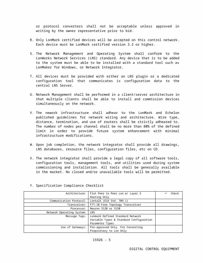
Y. Specification Compliance Checklist
Architecture: Flat Peer to Peer Lon w/ Layer 3 Routing Only
Check
Communication Protocol: Lontalk (EIA Std. 709.1)Transceiver: FTT-10 Free Topology Transceiver
Processor: Neuron 3120 or 3150Network Operating System: LNS
Message Tags: Lonmark Defined Standard Network Variable Types & Standard Configuration Parameter Types
Use of Gateways: Pre-approved Only. For Converting Proprietary to Lon Only
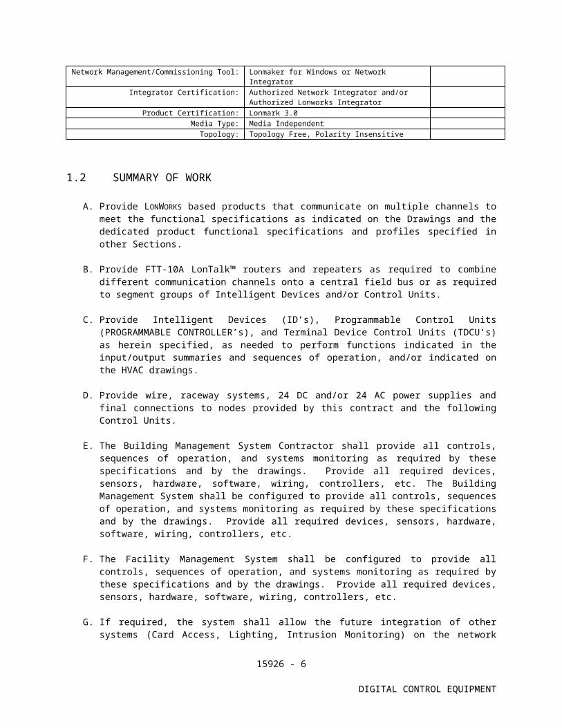
Network Management/Commissioning Tool: Lonmaker for Windows or Network Integrator
Integrator Certification: Authorized Network Integrator and/or Authorized Lonworks Integrator
Product Certification: Lonmark 3.0Media Type: Media Independent
Topology: Topology Free, Polarity Insensitive
1.2 SUMMARY OF WORK
A. Provide LONWORKS based products that communicate on multiple channels to meet the functional specifications as indicated on the Drawings and the dedicated product functional specifications and profiles specified in other Sections.
B. Provide FTT-10A LonTalk™ routers and repeaters as required to combine different communication channels onto a central field bus or as required to segment groups of Intelligent Devices and/or Control Units.
C. Provide Intelligent Devices (ID’s), Programmable Control Units (PROGRAMMABLE CONTROLLER’s), and Terminal Device Control Units (TDCU’s) as herein specified, as needed to perform functions indicated in the input/output summaries and sequences of operation, and/or indicated on the HVAC drawings.
D. Provide wire, raceway systems, 24 DC and/or 24 AC power supplies and final connections to nodes provided by this contract and the following Control Units.
E. The Building Management System Contractor shall provide all controls, sequences of operation, and systems monitoring as required by these specifications and by the drawings. Provide all required devices, sensors, hardware, software, wiring, controllers, etc. The Building Management System shall be configured to provide all controls, sequences of operation, and systems monitoring as required by these specifications and by the drawings. Provide all required devices, sensors, hardware, software, wiring, controllers, etc.
15926 - 5
DIGITAL CONTROL EQUIPMENT
F. The Facility Management System shall be configured to provide all controls, sequences of operation, and systems monitoring as required by these specifications and by the drawings. Provide all required devices, sensors, hardware, software, wiring, controllers, etc.
G. If required, the system shall allow the future integration of other systems (Card Access, Lighting, Intrusion Monitoring) on the network proposed in this document, and also share common software for network communications, time scheduling, alarm handling, and history logging.
1.3 PRODUCTS FURNISHED BUT NOT INSTALLED UNDER THIS SECTION.
1. Control Valves2. Sensor Wells
1.4 QUALITY ASSURANCE
A. General
1. The HVAC Control System shall be furnished, engineered, and installed by Licensed Trade Technicians. The contractor shall be an Echelon Certified Network Integrator or LonWorks Integrator. The contractor shall employ technicians who have completed Echelon factory authorized training. The contractor shall employ technicians to provide instruction, routine maintenance, and emergency service within 24 hours upon receipt of request.
B. System Integrator Qualifications
1. The system integrator must be regularly engaged in the service and installation of Lonworks based systems as specified herein, and must have been so for a minimum of three (3) years.
2. The system integrator must be an authorized representative in good standing of the manufacturer of the proposed hardware and software components, and must have been so for a minimum of three (3) years.
3. The system integrator shall have an office that is staffed with designers trained in integrating interoperable systems and technicians fully capable of providing Lonworks instruction and routine emergency maintenance service on all system components.
4. The system integrator shall have in house capabilities to provide control strategies for whole building control. This includes HVAC, lighting, access, and security applications.
5. The system integrator shall have a service facility, staffed with qualified service personnel, capable of providing instructions and routine emergency maintenance service for networked control systems.
15926 - 6
DIGITAL CONTROL EQUIPMENT
6. The system integrator shall Submit a list of no less than three(3) similar projects, which have Lonworks based Building Systems as specifed herein installed by the system integrator These projects must be on-line and functional such that the Owners/Users representative can observe the system in full operation.
7. The system integrator must be a certified Lonworks Integrator, or submit resumes with the proposal indicating passing certificates for Echelon Corporation’s approved interoperable, or proof of equivalent training. Such proof must include summary of coursework and indicate both written and laboratory requirements of alternate training.
C. Hardware and Software Component Manufacturer Qualifications
1. The manufacturer of the hardware and software components must be primarily engaged in the manufacture of Lonworks based systems as specified herein, and must have been so for a minimum of three (7) years.
2. The manufacturer of the hardware and software components as well as its subsidiaries must be a member in good standing of the LonMark Organization.
3. The manufacturer of the hardware and software components shall have an authorized representative capable of providing service and support as referenced in section B above, and must have done so for a minimum of three (3) years.
4. The manufacturer of the hardware and software components shall have a technical support group accessible via a toll free number that is staffed with qualified personnel, capable of providing instruction and technical support service for networked control systems.
5. The manufacturer of the hardware and software components must be authorized to certify Lonworks Integrators as defined by Echelon Corporation. They also must provide for Echelon Corporation’s approved Lonworks curriculum.
6. The manufacturer of the hardware and software components must have no less than three(3) similar projects, which have Lonworks based building systems as specified herein installed by the authorized representative referenced above. These projects must be on-line and functional such that the Owners/Users representative can observe the system in full operation.
Acceptable manufacturers of the hardware and software components as specified herein are as follows:
A. Reference Standards
15926 - 7
DIGITAL CONTROL EQUIPMENT
1. Control system components shall be new and in conformance with the following applicable standards for products specified:
a. LonMark certified 3.2 or higher, and LNS Based.b. ANSI EIA 709.1 LonTalk Protocol
B. Products
1. Utilize standard PC components for all assemblies. Custom hardware, operating system, and utility software are not acceptable.
2. All products (PROGRAMMABLE CONTROLLER’s, TDCU’s and ID’s) shall contain ANSI EIA 709.1 LonTalk Protocol networking elements to allow ease of integration of devices from multiple vendors.
3. All materials, equipment and software shall be standard components, regularly manufactured for this and other systems and custom designed for this project. All systems and components shall be thoroughly tested.
1.5 SUBMITTALS
SPEC WRITER: EDIT TO SUIT PROJECT SPECIFIC REQUIREMENTS.
A. General: Submit the following according to conditions of Contract and Division 15 Specification sections. In addition, provide the following:
1. Product data on all components used to meet the requirements of the specifications such as enclosures, network transceivers, Resource files, LNS Plugins, XIF documentation, configuration parameter options, mounting details, power supplies, etc.
2. Software documentation regarding the proposed PC operating system, third party utilities and application programs, and the proposed application program for the Control Units.
3. Logical and physical diagrams for each channel indicating each node (control devices and ID’s), node address (domain, subnet and group), channel type and router specifications.
4. Submit functional temperature control diagrams for each Mechanical system served by the HVAC Control System. Indicate and Tag each input/output served by each Control Unit or Intelligent Device.
5. Submit 8 sets of submittals for review within 3 weeks of contract award.
B. Shop Drawings
1. The controls contractor shall submit AutoCAD or Visio generated schematic drawings for the entire control system for review and approval before work shall begin. Included in the submittal drawings shall be a one-page diagram depicting the complete system architecture complete with a communications riser.
15926 - 8
DIGITAL CONTROL EQUIPMENT
Drawings shall include point-to-point wiring diagrams and must show all temperature controls, start-stop arrangement for each piece of equipment, equipment interlocks, wiring terminal numbers and any special connection information required for properly controlling the mechanical equipment. The submittal shall include a bill of material reference list as well as equipment sequences of operation.
2. The submittals shall include manufacturer's catalog data describing each item of control equipment or component provided and installed for the project.
3. System Color Graphics using the AutoCAD or Visio generated schematic drawings. Dynamic points, menus icons, commandable points, etc. should be clearly identified.
4. Color conventions proposed for all graphics.
C. Close-Out Documents
1. Submit final copies of the shop drawings outlined in paragraph B above. These final submittals shall reflect all field modifications and change orders required to complete the installation. Submit the following quantities of record submittal drawings immediately following receipt of notification of substantial completion. Auto CAD drawing or VISIO files of all shop drawings on 3-1/2” floppy disks or CD ROM disks.
2. Three complete sets of documents located in a three-ring notebook and organized by subject with divider tabs.
1.6 OPERATION AND MAINTENANCE MANUALS
A. Submit 3 sets of operation and maintenance manual in accordance with requirements of Division 15.
B. Include the following documentation:
1. Network Management Software User Manual specific to each tool package provided.
2. Maintenance Instructions: Document all maintenance and repair/ replacement procedures. Provide ordering number for each system component, and source of supply. Provide a list of recommended spare parts needed to minimize downtime.
3. Documentation of network variables, network node configurations, priority interrupts, node binding, addressing structure, etc.
1.7 INSTRUCTION OF OWNER OPERATING PERSONNEL
SPEC WRITER: EDIT TO SUIT PROJECT SPECIFIC REQUIREMENTS.
A. All training shall be by the HVAC Controls Contractor and shall utilize specified manuals, as-built documentation, and the on-line help utility.
15926 - 9
DIGITAL CONTROL EQUIPMENT

B. Operator training shall include four initial eight-hour sessions. The initial operator training program shall be to establish a basic understanding of Windows based software, functions, commands, mouse, etc. The training shall encompass as a minimum:
1. Troubleshooting of input devices, i.e., bad sensors.2. Sequence of operation review.3. Sign on - sign off.4. Selection of all displays and reports.5. Commanding of points, keyboard and mouse mode.6. Modifying English text7. Use of all dialogue boxes and menus.8. System initialization.9. GUI Software.10. LonWorks® Network Management Software.
1.8 ACCEPTANCE PROCEDURE
A. Upon completion of the installation, Contractor shall start-up the system and perform all necessary calibration and testing to ensure proper operation of the project control systems.
B. Schedule a hardware demonstration and system acceptance test in the presence of the Contracting Officer and/or the Engineer. The acceptance testing is defined as demonstrating the sequence of operation as indicated in the drawings. The hardware demonstration is specified in this Section. The Contractor shall perform all tests prior to scheduling the acceptance test and hardware demonstration to insure the overall system is ready for inspection and observations.
C. When the system performance is deemed satisfactory in whole or in part by these observers, the system parts will be accepted for beneficial use and be deemed substantially complete as defined in Division 1.
1.9 WARRANTY
A. The HVAC Control System shall be free from defects in workmanship and material under normal use and service. If within eighteen (18) months from the date of substantial completion, the installed equipment is found to be defective in operation, workmanship or materials, the building systems contractor shall replace, repair or adjust the defect at no cost. Service shall be provided within 4 hours upon notice from Owner’s designated Representative.
B. The warranty shall extend to material that is supplied and installed by the Contractor. Material supplied but not installed by the Contractor shall be covered per the above to the extent of the product only. Installation labor shall be the responsibility of the trade contractor performing the installation.
15926 - 10
DIGITAL CONTROL EQUIPMENT
C. All corrective software modifications made during warranty service periods shall be updated on all user documentation and on user and manufacturer archived software disks.
1.10 PRODUCT DELIVERY, STORAGE AND HANDLING
A. Do not install electronic hardware in the project until non-condensing environmental conditions have been established. Products installed in violation of this request maybe requested to be replaced at no additional cost to the project.
B. Coordinate storage requirements for factory mounted terminal control units on air terminal devices, air handling units or other packaged control equipment. Do not store control units on site in non-conditioned areas for more than two weeks.
C. Factory-Mounted Components: Where control devices specified in this section are indicated to be factory mounted on equipment, arrange for shipping control devices to unit manufacturer.
PART 2 – PRODUCTS
2.0 CENTRAL OPERATOR’s WORKSTATION
A. General Requirements
1. A personal computer (PC) based workstation, with Pentium processor, 1Ghz minimum clock speed, minimum 128 MB of RAM, 1 diskette drive, 10 Meg Hard drive suitable for peripherals and applications and 12X speed CDRW Drive. Operator Workstation shall include mouse, keyboard, and 19-inch color monitor and an internal or external modem (56k baud minimum) connected to a PC COM port.
2. The System shall support multiple Operators’ Work Stations.3. The Workstation shall not function as a dedicated control device
to the network. It shall be connected to the LonWorks network via standard LonWorks network connection devices.
B. OPERATOR INTERFACE SOFTWARE
1. The Interface software shall utilize Microsoft Windows 98/2000 based operating and utility software.
2. The graphical user interface software shall be as outlined in “User Interface Software” below.
3. The Interface Software will not act as a control component for the network. In particular, it shall not perform the following functions:
SPEC WRITER NOTE: EDIT TO SUIT PROJECT REQUIREMENTS.
15926 - 11
DIGITAL CONTROL EQUIPMENT

a. HVAC Global Sequence of Operation.b. Electrical Demand Limiting.c. Time of day synchronization for the network as desired by
system operator
2.1 PROGRAMMABLE CONTROL UNIT
A. General Requirements
1. Control Units shall be LonMark 3.2 Certified or higher, and equipped with 3150 Neuron microprocessor as manufactured by Toshiba or Cypress for communications. There shall be intermediate device between the Neuron chip and the input and output channels. As referenced above, “Hosted” controllers that utilize a 3rd party chip for communications processing are not acceptable. The controller shall have a minimum of 32K programmable non-volatile (flash or EEPROM) memory for general data processing, power supply, input/output modules, termination blocks, and network transceivers.
2. System controllers shall share network variable data with other LON-based devices that utilize the same transceivers as refernced in section 1.1 paragraph Q above.
3. Operating system software, custom operating sequence software and application programs shall be stored in programmable, non-volatile memory.
4. The programmable controllers shall be equipped with a dedicated software clock battery. The battery shall be capable of maintaining time of day, day of week, date, month, and year, independent of system power for a 2-week period. Include an integral calendar with automatic leap year compensation. The programmable controller will provide time synchronization with TDCU’s when required.
5. programmable controller packaging shall be such that complete installation and checkout of field wiring can be performed prior to the installation of electronic boards. Make all board terminations facilitate troubleshooting, repair and replacement. The complete programmable controller including accessory devices such as relay, transducers, power supplies, etc., shall be wired and housed in an enclosure or as required by the location and local code requirements.
6. Provide programmable controller boards with (1) RJ-45 or mono jacks to provide an optional communication link.
7. Equip programmable controller with diagnostic indicators for the following:
a. Transmit.b. Receive.c. IMOK – Application Program is running correctly
15926 - 12
DIGITAL CONTROL EQUIPMENT
B. Input/Output Requirements
1. At least 50% of the PROGRAMMABLE CONTROLLER Inputs shall be Universal type capable of handling current, voltage, resistance, or open and closed contacts in any mix. Analog current and voltage inputs of the following types shall be supported in the programmable controller.
a. 4-20 Ma.b. 0-1 volt.c. 0-5 volt.c. 0-10 volt.d. 2-10 volt.e. 1000 ohm RTD or 10K ohm thermistor
1. Provide programmable intermediate ranges and linearization table for sensor types specified under the heading, "Sensors". Standard linearization tables will be available for common sensors.
2. Thermistor type temperature sensors shall require programmable calibration constant unique to a specific resistance group.
3. Digital input types supported by the CU:
4. Normally open contacts. (24V and 120V)5. Normally closed contacts. (24V and 120V)
6. The programmable controller shall accommodate both digital and true analog outputs. Voltage (0-12V) and current (4-20 mA) outputs shall be accommodated. All analog outputs shall be proportional current or voltage type with a minimum incremental resolution of 0.5% of the full operating range of the output. Match the proportional range of the output to the full operating range of the actuating device. Use zero and maximum output voltage or current values for shutdown and close-off modes. For troubleshooting and load analysis, the value of each analog output shall be available in the database for trending and display.
7. The analog/digital resolution process shall be 12 bit based. The digital to analog resolution process shall be a minimum of 12 bits.
C. Accessories: Provide the following with each Plant Control Unit:
1. On/Off switch.2. Over current and transient power protection.
D. Programmable Controller Software
1. General: A programmable controller shall operate totally stand-alone and independent of a central computer or master device such as a schedule module, for all specified control applications including scheduling, and trending. Software shall include a complete operating system (O.S.), communications
15926 - 13
DIGITAL CONTROL EQUIPMENT
handler, point processing, standard control algorithms, and specific control sequences.
2. O.S. software shall reside in programmable battery backed RAM, operate in real-time, provide prioritized task scheduling, control time programs, and scan inputs and outputs. O.S. shall also contain built in diagnostics.
3. It shall be possible to make changes to the application program and/or configuration of any controller in realtime with no interupption of the operation of the controlled equipment. Systems that require that the controller be taken offline and/or require the shutdown of the controlled equipment are not acceptable.
4. Input/Output Point Processing Software shall include:
a. Continuous update of input and output values and conditions. All connected points are to be updated at a minimum of one-second intervals.
b. Assignment of proper engineering units and status condition identifiers to all analog and digital input and outputs.
c. Analog input alarm comparison with the ability to assign two individual sets of high and low limits (warning and actual alarm) to an input or to assign a set of floating limits (alarm follows a reset schedule or control point) to the input. Each alarm shall be assigned a unique differential to prevent a point from oscillating into and out of alarm. Alarm comparisons shall be made each scan cycle.
4. Command Software
a. A "fixed mode" option shall be supported to allow inputs to, and outputs from DDC control programs to set to a fixed state or value. When in the "fixed mode" inputs and output shall be assigned a high residual command priority to prevent override by application programs.
5. Run Time Totalization or Point Trending:
a. Run time shall be accumulated based on the status of a digital output point. It shall be possible to totalize either on time or off time up to 60,000 hours with one-minute resolution. Run time counts shall be resident in non-volatile memory and have CU resident run time limits assignable through the operator's terminal.
b. Totalized run time or trended data shall be batch downloaded to the Workstation on a daily or weekly basis. Trended data shall reside on the User Interface database server. The automatic update of this data shall be determined by the User Interface and facility management application requirements.
6. Transition Counting: A transition counter shall be provided to accumulate the number of times a device has been cycled on or off. Counter is to be non-volatile and be capable of accumulating 60,000 switching cycles. Limits shall be assignable to counts to provide maintenance alarm printouts.
15926 - 14
DIGITAL CONTROL EQUIPMENT
7. Custom DDC Control Loops
a. Custom DDC programs are to be provided to meet the control strategies as called for in the sequence of operation sections of these specifications. Each CU shall have residential in its memory and available to the programs a full library of DDC algorithms, intrinsic control operators, arithmetic, logic and relational operators for implementation of control sequences:
1) Proportional Control, Proportional plus Integral (PI), and Proportional plus Integral plus Derivative (PID).
2) DDC control programs shall include an assignment of initialization values to all outputs to assure that controlled devices assume a fail-safe position on initial system start-up.
2.2 TERMINAL DEVICE CONTROL UNIT (TDCU)
A. General Requirements
Control Units shall be LonMark 3.2 Certified or higher, and equipped with a 3150 Neuron microprocessor controller, programmable non-volatile memory for general data processing, power supply, input/output modules, termination blocks, network transceivers.
1. System controllers shall be capable of sharing network variable data with other LON-based devices that utilize the same transceivers.
2. Operating system software, custom operating sequence software and application programs shall be stored in programmable, non-volatile memory.
3. It shall be possible to make changes to the application program and/or configuration of any controller in realtime with no interupption of the operation of the controlled equipment. Systems that require that the controller be taken offline and/or require the shutdown of the controlled equipment are not acceptable.
4. The TDCU shall synchronize time with a PROGRAMMABLE CONTROLLER on the network upon power up of the network.
5. TDCU packaging shall be such that complete installation and check-out of field wiring can be performed prior to the installation of electronic boards. Make all board terminations facilitate troubleshooting, repair and replacement. The complete CU including accessory devices such as relay, transducers, power supplies, etc., shall wired and housed in an enclosure or as required by the location and local code requirements.
B. Input/Output Requirements
1. The TDCU Inputs shall be capable of handling current, voltage, resistance, or open and closed contacts in any mix. Analog
15926 - 15
DIGITAL CONTROL EQUIPMENT
current and voltage inputs shall be supported in the TDCU when appropriate for the as is appropriate for the application.
2. As is appropriate for the applications, the Digital input types supported by the TDCU are:
a. Normally open contacts. (24V)b. Normally closed contacts. (24V)c. Voltage/no voltage.
3. The TDCU shall accommodate both digital and analog outputs when appropriate for the application. Voltage (0-12V) outputs shall be accommodated. All analog outputs shall be proportional voltage type with a minimum incremental resolution of 0.5% of the full operating range of the output. Match the proportional range of the output to the full operating range of the actuating device. Use zero and maximum output voltage or current values for shut-down and close-off modes. For troubleshooting and load analysis, the value of each analog output shall be available in the database for trending and display.
4. Digital outputs shall be capable of handling maintained as well as pulsed outputs for momentary or magnetic latching circuits. It shall be possible to configure outputs for 3-mode control (fast-slow-off) and 2-mode control.
5. The analog/digital resolution process shall be 10 bit based. The digital to analog resolution process shall be a minimum of 8 bit.
D. TDCU Software
1. General: A TDCU shall operate totally standalone and independent of a central computer for all specified control applications. Software shall include a complete operating system (O.S.), communications handler, point processing, standard control algorithms, and specific control sequences.
2. O.S. software shall reside in programmable flash memory, operate in real-time, provide prioritized task scheduling, control time programs, and scan inputs and outputs. O.S. shall also contain built in diagnostics.
3. TDCU’s shall have canned programs to minimize configuration and installation time. Canned programs shall be able to be changed so the same hardware component can be utilized in the event the mechanical equipment is removed, and new mechanical equipment has been added. TDCU’s shall also be available in a programmable version for unique equipment sequences of operation.
3. Input/Output Point Processing Software shall include:
a. Continuous update of input and output values and conditions. All connected points are to be updated at a minimum of one second intervals.
b. Assignment of proper engineering units and status condition identifiers to all analog and digital input and outputs.
c. Analog input alarm comparison with the ability to assign two individual sets of high and low limits (warning and actual alarm) to an input or to assign a set of floating limits
15926 - 16
DIGITAL CONTROL EQUIPMENT
(alarm follows a reset schedule or control point) to the input. Each alarm shall be assigned a unique differential to prevent a point from oscillating into and out of alarm. Alarm comparisons shall be made each scan cycle.
4. Command Software
a. A "fixed mode" option shall be supported to allow inputs to, and outputs from DDC control programs to set to a fixed state or value. When in the "fixed mode" inputs and output shall be assigned a high residual command priority to prevent override by application programs.
2.3 NETWORK INTERFACES, LON ROUTERS, BRIDGES, REPEATERS AND TRANSCEIVERS
A. Internet servers, Routers, Bridges and Repeaters
1. Equip each internet server, router and bridge with a network transceiver on each network port (inbound and outbound) as dictated by the network type (Type 1 - FTT, Type 2 - TP, Type 3 - PL, Type 4 - LP, Type 5 - RF).
2. The network router shall be designed to route messages from a segment, sub-net, or domain in full duplex communication mode.
3. Routers and bridges shall utilize LonTalk® protocol transport, network, session layers to transparently route messages bound for a node address in another sub-net or domain exclusively.
4. Routers, bridges and repeaters shall be fully programmable and permit a systems integrator to define message traffic, destination, and other network management functions utilize LonWorks®. Devices used for routing, bridging, or repeas
5. The routers, bridges, and repeaters shall be capable of DIN rail or panel mounting and be equipped with status LED lights for Network traffic and power.
6. Internet servers, and routers shall be Cisco certified7. Internet servers shall support read, write, and overwriting of
points as well as alarm management, trending and scheduling functions.
B. Transceivers:
1. Type 1 Network Transceiver, Free Topology, and Twisted Pair: Provide a transformer isolated, twisted pair transceiver capable of mounting directly on a printed circuit board. The transceiver shall meet the following specifications:
a. Meets LONMARK™ Interoperability Association Standards.b. Differential Manchester encoded signaling for polarity
insensitive network wiring.c. Transformer isolated for common mode rejection.d. 78kbs network bit rate up to distances of 2000m.
2.4 ELECTRONIC INPUT/OUTPUT DEVICES
15926 - 17
DIGITAL CONTROL EQUIPMENT
A. Temperature Sensors and Transmitters
1. General Sensor & Transmitter Requirements
a. Provide sensors and transmitters required as outlined in the input/output summary and sequence of operation, and as required to achieve the specified accuracy as specified herein.
b. Temperature transmitters shall be equipped with individual zero and span adjustments. The zero and span adjustments shall be non-interactive to permit calibration without iterative operations. Provide a loop test signal to aid in sensor calibration.
c. Temperature transmitters shall be sized and constructed to be compatible with the medium to be monitored. Transmitters shall be equipped with a linearization circuit to compensate for non-linearities of the sensor and bridge and provide a true linear output signal.
d. Temperature sensors shall be of the resistance type and shall be either three-wire 100 ohm platinum RTD, or two-wire 1000 ohm platinum RTD.
e. Thermistors are acceptable provided the mathematical relationship of a thermistor with respect to resistance and temperature with the thermistor fitting constraints is contained with the CU operating software and the listed accuracy’s can be obtained. Submit proof of the software mathematical equation and thermistor manufacturer fitting constants used in the thermistor mathematical/expressions. Thermistors shall be of the Thermistor (NTC) Type with a minimum of 100 ohm/F. resistance change versus temperature to insure good resolution and accuracy. Thermistors shall be certified to be stable ±0.24F. over 5 years and ±0.36F. accurate and free from drift for 5 years.
f. CU operating software shall be equipped with a self-calibrating feature for temperature sensors.
g. The following accuracy’s are required and include errors associated with the sensor, lead wire and A to D conversion.
Point Type AccuracyOutside Air 0.5F.Chilled Water 0.5F.Room Temperature 1.00F.Hot Water/Steam 0.75F.Duct Temperature 0.5F.Sensors Used in EnergyWater (BTU) or ProcessCalculations 0.1F.
h. Sensors used in BTU or process calculations shall be accurate to ±0.10F. over the process temperature range. Submit a manufacturer's calibration report indicating that the calibration certification is traceable to the National Bureau of Standards (NBS) Calibration Report Nos. 209527/222173.
15926 - 18
DIGITAL CONTROL EQUIPMENT
2. Thermowells
a. When thermowells are required, the sensor and well shall be supplied as a complete assembly including well head and greenfield fitting.
b. Thermowells shall be pressure rated and constructed in accordance with the system working pressure
c. Thermowells and sensors shall be mounted in a threadolet or 1/2" NPT saddle and allow easy access to the sensor for repair or replacement.
d. Thermowells shall be constructed of the following materials:
1) Chilled and Hot Water; brass.2) Steam; 316 stainless steel.3) Brine (salt solutions): marine grade stainless steel.
3. Outside Air Sensors
a. Outside air sensors shall be designed to withstand the environmental conditions to which they will be exposed. They shall also be provided with a solar shield.
b. Sensors exposed to wind velocity pressures shall be shielded by a perforated plate surrounding the sensor element.
c. Temperature transmitters shall be of NEMA 3R construction and rated for ambient temperatures.
4. Duct Type Sensors
a. Duct mount sensors shall mount in a hand box through a hole in the duct and be positioned so as to be easily accessible for repair or replacement. A neoprene grommet (sealtite fitting and mounting plate) shall be used on the sensor assembly to prevent air leaks.
b. Duct sensors shall be insertion type and constructed as a complete assembly including lock nut and mounting plate. Duct sensors probe shall be constructed of 304 stainless steel.
c. For outdoor air duct applications, use a weatherproof mounting box with weatherproof cover and gasket.
5. Averaging Duct Type Sensors
a. For ductwork greater any dimension than 48 inches and/or where air temperature stratification exists, utilize an averaging sensor with multiple sensing points. The averaging sensor shall be a 304 stainless steel tube with holes extending across the duct or plenum to be sampled. A bleed hole outside the duct or plenum causes air to enter the sample tube and exit at the bleed hole, thus bathing the sensor in average air. The averaging sensor shall be installed complete with end cap, compression fittings, gaskets, mounting flange and required accessories.
b. Provide capillary supports at the sides of the duct to support the sensing string.
15926 - 19
DIGITAL CONTROL EQUIPMENT
6. Intelligent LonWorks Room Sensors
a. Room temperature sensors are to be provided with a cover to prevent accidental damage.
b. Terminal unit temperature sensors all be of the thermistor (NTC) type with a 100 ohm/oF. resistance change versus temperature change to insure good resolution and accuracy. Thermistor shall produce 3000 ohms at 77F. for calibration.
c. Sensor shall be supplied with a vertical base for mounting on a standard single gang junction box supplied by the SI contractor.
d. Provide an integrated thermistor, Neuron chip and FTT Transceiver for communication with the PROGRAMMABLE CONTROLLER communication network.
e. Room Temperature sensor shall be a digital type with a digital display and setpoint adjustment.
7. Acceptable Manufacturers
a. Duct/Immersion Sensors – BAPI or ACIb. Room Sensors – Crystal Controls or Smart Controlsc. Preapproved equal
B. Relative Humidity Sensors/Transmitter
1. The sensor shall be a solid state, resistance type relative humidity sensor of the Bulk Polymer Design. The sensor element shall be washable and shall resist surface contaminations.
2. Humidity transmitter shall be equipped with non-interactive span and zero adjustments, a 2 wire isolated loop powered, 4-20ma, 0-10 vdc linear proportional output.
3. The humidity transmitter shall meet the following overall accuracy including lead loss and A to D conversion.
a. Room Type Sensor ±3% RH
4. Provide a single point humidity calibrator, if required, for field calibration. Transmitters shall be shipped factory pre-calibrated.
5. Acceptable Manufacturers:
a. BAPIb. ACIc. VERISd. HYCALe. Preapproved equal
C. Differential Pressure Transmitters and Accessories
1. General Air and Water Pressure Transmitter Requirements:
15926 - 20
DIGITAL CONTROL EQUIPMENT
a. Pressure transmitters shall be constructed to withstand 100% pressure over-range without damage and to hold calibrated accuracy when subject to a momentary 40% over-range input.
b. Pressure transmitters shall provide the option to transmit a 0 to 5V dc, 0 to 10V dc, or 4 to 20 mA output signal.
c. Differential pressure transmitters used for flow measurement shall be sized to the flow-sensing device and shall be supplied with shutoff and bleed valves in the high and low sensing pick-up lines (3 valve manifolds).
d. Provide a minimum of a NEMA 1 housing for the transmitter. Locate transmitters in accessible local control panels wherever possible.
e. Low air pressure, differential pressure transmitters used for room filter monitoring. Shall be equipped with a LED display indicating the transmitter output signal.
2. Low Air Pressure Applications (0 to 0.5” WC)
a. The pressure transmitter shall be capable of transmitting a linear electronic signal proportional to the differential of the room and reference static pressure input signals with the following minimum performance specifications.
1) Span: Not greater than two times the design space DP.2) Accuracy: Plus or minus 0.5% of F.S.3) Dead Band: Less than 0.3% of output.4) Repeatability: Within 0.2% of output.5) Linearity: Plus or minus 0.2% of span.6) Response: Less than one second for full span input.7) Temperature Stability: Less than 0.01% output shift
per degree F. change.
b. The transmitter shall utilize variable capacitance sensor technology and be immune to shock and vibration.
c. Provide a two-year warranty for each transmitter. Replace all transmitters found to be defective at no cost to the Owner during the warranty period. Acceptable Manufacturers:
1) VERIS - Model PXL1002) Or preapproved equal
D. Flow, Pressure, and Electrical Measuring Apparatus
1. Traverse Probe Air Flow Measuring Stations
a. Traverse probes shall be a dual manifolded, cylindrical, type constructed of 3003 extruded aluminum with an anodized finish to eliminate surface pitting and unnecessary air friction. The multiple total pressure manifold shall have sensors located along the stagnation plane of the approaching air flow and without the physical presence of forward projecting sensors into the airstream. The static pressure manifold shall incorporate dual offset static tips on opposing sides of the averaging manifold so as to be insensitive to flow-
15926 - 21
DIGITAL CONTROL EQUIPMENT
angle variations of as much as ±20o in the approaching airstream.
b. The air flow traverse probe shall not induce a measurable pressure drop, nor shall the sound level within the duct be amplified by its singular or multiple presence in the air stream. Each airflow-measuring probe shall contain multiple total and static pressure sensors placed at equal distances along the probe length. The number of sensors on each probe and the quantity of probes utilized at each installation shall comply with the ASHRAE Standards for duct traversing.
c. Traverse probes shall be accurate to ±25% of the measured airflow range down to 0.25” wc static pressure.
d. Each flow measuring station shall be complete with its own dedicated microprocessor with a 4-line, 80 character, Alpha Numeric display and full function key pad. The panel shall be fully programmable and display calculated CFM directly on a LED monitor on the panel face.
e. Each station shall log air flow rates in real time and download data to its control unit (CU) via a RS-232 interface.
f. Provide 24 volt 1 phase power to each flow measuring station.g. Acceptable Manufacturers: Air Monitor, Brandt, Air Sentinel.
Or pre-approved equal
E. Shielded Static Pressure Sensor
a. Provide for each zone where required a shielded static pressure sensor suitable for ceiling surface mounting, complete with multiple sensing ports, pressure impulse suppression chamber with minimum volume of 50 cubic inches, airflow shielding, and 3/8" compression takeoff fittings, all contained in a welded stainless steel casing, with polish finish on the exposed surfaces.
b. These probes shall be capable of sensing the static pressure in the proximity of the sensor to within 1% of the actual pressure value while being subjected to a maximum airflow of 1000 FPM from a radial source.
c. The shielded static sensing devices shall be used for both reference and space pressure sensing.
d. Pressure sensors used for outside air pressure reference purposes shall be equipped with a conduit seal for pneumatic tubing and bushings for a weather tight installation.
F. Static Pressure Traverse Probe
a. Provide multipoint traverse probes in the duct at each point where static pressure sensing is required.
b. Each duct static traverse probe shall contain multiple static pressure sensors located along the exterior surface of the cylindrical probe. Pressure sensing points shall not protrude beyond the surface of the probe.
c. The duct static traverse probe shall be of 304 stainless steel construction and (except for 3/4" dia. probes with lengths of 24" or less) be complete with threaded end support rod, sealing washer and nut, and mounting plate with gasket
15926 - 22
DIGITAL CONTROL EQUIPMENT
and static pressure signal fitting. The static traverse probe shall be capable of producing a steady, nonpulsating signal of standard static pressure without need for correction factors, with an instrument accuracy of 21.
G. Venturi Flow meter
a. Pressure drop on venturi type flowmeters shall not exceed 0.25" wc. Each venturi low and high pressure taps shall be equipped with nipples, valves and quick disconnects.
b. Equip each venturi with a metal identification tag indicating the size, location, GPM and meter reading for the GPM specified.
c. Provide (1) 6" dial differential pressure meter of the proper range to determine piping system flow rate. The meter shall be the property of the Owner.
d. Venturi meters shall utilize flanged or screwed connections for removal purposes and shall be rated for the system operating pressures.
e. The venturi flowmeter shall be factory calibrated to provide a minimum of flow accuracy between actual and factory flow calibration data.
H. Current Transformers
a. The current transformers shall be designed to be installed or removed without dismantling the primary bus or cables. The transformer shall be of a split core design.
b. The core and windings shall be completely encased in a UL approved thermoplastic rated 94VA. No metal parts shall be exposed other than the terminals.
c. The current transformers shall meet the following specifications:
d. Frequency Limits: 50 to 400 Hz.e. Insulation: 0.6 KV Class, 10 KV BIL.f. Accuracy: 1% at 5.0 to 25.0 VA accuracy class with U.P.F.
burden.g. Provide a disconnect switch for each current transformer.
I. Current Sensing Switches
a. Current sensing switch shall be self-powered with solid state circuitry and a dry contact output. Current sensing switches shall consist of a solid state current sensing circuit, adjustable trip point, solid state switch, SPDT relay and an LED indicating the on or off status. A conductor of the load shall be passed through the window of the device. It shall accept overcurrent up to twice its trip into range.
J. Electronic Valve & Damper Actuators
1. General Requirements
15926 - 23
DIGITAL CONTROL EQUIPMENT
a. Electronic actuators shall be electric, direct-coupled type capable of being mounted over the shaft of the damper. They shall be UL listed and the manufacturer shall provide a 2-year unconditional warranty from the date of commissioning. Power consumption shall not exceed 8 watts or 15 VA of transformer sizing capacity per high torque actuator nor 2 watts or 4 VA for VAV actuators.
b. Electronic overload protection shall protect actuator motor from damage. If damper jams actuator shall not burnout. Internal end switch type actuators are not acceptable. Actuators may be mechanically and electrically paralleled on the same shaft to multiply the available torque. A reversing switch shall be provided to change action from direct to reverse in relation to control signal as operation requires.
2. Combination Smoke and Fire Damper Actuators
a. Actuators shall be factory mounted and connected to the damper section and shall conform to UL 555S specifications. They shall be rated for 350F.
K. Valve Actuators
1. Control Valves Actuators (3 inch and smaller)
a. Actuators shall have a gear release button on all non-spring return models to allow manual setting. The actuator shall have either an insulating air gap between it and the linkage or a non-conducting thermoplastic linkage. Care shall be taken to maintain the actuator's operating temperatures and humidity within its specifications. Pipes shall be fully insulated and heat shields shall be installed if necessary. Condensation may not form on actuators and shall be prevented by a combination of insulation, air gap, or other thermal break.
b. The control circuit shall be fully modulating using 2 - 10 volt or 4 - 20 mA signals. Accuracy and repeatability shall be within 1/21 of control signal. A 2 - 10 v or 4 - 20 mA signal shall be produced by the actuator which is directly proportional to the shaft clamp position which can be used to control actuators which are paralleled off a master motor or to provide a feedback signal to the automation system indicating valve position.
c. Valve body and actuators shall be shipped fully assembled and tested at the valve factory prior to shipment.
d. Acceptable Manufacturers: BELIMO ONLY
2. Control Valve Actuators (4 inch and larger).
a. The valve actuator shall consist of a permanent split capacitor, reversible type electric motor that drives a compound epicycle gear. The electric actuator shall have visual mechanical position indication, readable from a distance of 25 feet, showing output shaft and valve
15926 - 24
DIGITAL CONTROL EQUIPMENT
position. Unit shall be mounting directly to the valves without brackets and adapters, or readily adapted to suit all other types quarter-turn valves.
b. The actuator shall have an integral terminal strip, which, through conduit entries, will ensure simple wiring to power supplies. Cable entries shall have UL recommended gland stops within the NPT hole to prevent glands from being screwed in too far and damaging cable.
c. The actuator shall be constructed to withstand high shock and vibrations without operations failure. The actuator cover shall have captive bolts to eliminate loss of bolts when removing the cover from the base. One copy of the wiring diagram shall be provided with the actuator.
d. The actuator shall have a self-locking gear train, which is permanently lubricated, at the factory. The gearing shall be run on ball and needle bearings. Actuators with 600 in/lbs. or more output torque shall have two adjustable factory calibrated mechanical torque limit switches of the single-pole, double-throw type. The motor shall be fitted with thermal overload protection. Motor rotor shaft shall run in ball bearings at each end of motor.
e. The actuator housing shall be hard anodized aluminum for full environmental protection.
f. The environmental temperature range of the actuator shall be -30C to +60C (-20F to +140F).
g. For intermittent on/off service, the actuator shall be rated at a 20% duty cycle (i.e., 12 minutes extended duty in every hour, or alternatively; one complete cycle every 2 minutes). For more frequent cycling and modulating service, an actuator shall be rated for continuous duty. The actuator rated for continuous duty shall be capable of operating 100% of the time at an ambient temperature of 40C.
h. The actuator shall have an integral self-locking gear train. Motor brakes shall not be required to maintain desired valve position. Levers or latches shall not be required to engage or disengage the manual override. Mechanical travel stops, adjustable to 15 in each direction of 90 rotation shall be standard, as well as two adjustable travel limit switches with electrically isolated contacts. Additional adjustable switches shall be available as option.
i. Single Phase Motor: The motor shall have Class B insulation capable of withstanding locked-rotor for 25 seconds without overheating. Wiring shall also be Class B insulation. An auto-reset thermal cutout protector shall be embedded in the motor windings to limit heat rise to 80C in a 40C ambient. All motors shall be capable of being replaced by simply disconnecting the wires and then removing mounting bolts. Disassembly of gears shall not be required to remove the motor.
j. Materials of Construction: The electric actuator shall have a pressure die-cast, hard-anodized aluminum base and cover. The compound gear shall be made of die-cast, hard-anodized aluminum or steel. An alloy steel worm gear shall be provided for manual override and torque limiting. Bearings
15926 - 25
DIGITAL CONTROL EQUIPMENT
for gears shall be of the ball and needle type; bronze bearings shall be used on the shafting parts.
k. Acceptable Manufacturers: BELIMO ONLY
2.5 CONTROL VALVES
A. General Control Valve Requirements
1. All automatic control valves shall be linear, fully proportioning, with modulating ball, plug or V-port inner guides unless otherwise specified. The valves shall be quiet in operation and fail safe in either normally open or normally closed position in the event of control air failure or loss of electronic output signal.
2. All valves shall be capable of operating in sequence when required by the sequence of operation. All control valves shall be sized by the control manufacturer, and shall be guaranteed to meet the heating and cooling loads as specified. All control valves shall be suitable for the pressure conditions, and shall close against the differential pressures involved. Valve body pressure rating and connection type (screwed or flanged) shall conform to ANSI pressure classifications appropriate for the system working pressures. Acceptable Manufacturers: BELIMO ONLY
B. Hot and Cold Water Control Valves
1. Hot and cold water globe type control valves shall be single-seated type, with equal percentage flow characteristics. The valve discs shall be composition type and shall be sized using ISA methods.
2. Pressure drop through the valves shall not exceed 5 psi unless otherwise indicated.
3. Ball valves shall be equipped with 316 stainless steel trim, Teflon seals and adjustable packing gland nuts. Provide a handle for manual operation during start-up and maintenance.
2.6 SWITCHES
A. Current Sensing Switches
1. Current sensing switch shall be self-powered with solid-state circuitry and a dry contact output. Current sensing switches shall consist of a solid state current sensing circuit, adjustable trip point, solid state switch, SPDT relay and an LED indicating the on or off status. A conductor of the load shall be passed through the window of the device. It shall accept over current up to twice its trip into range.
2.7 ELECTRICAL CONTROL POWER AND LOW VOLTAGE WIRING
A. Provide interlock wiring between supply and exhaust fans, electrical wiring for relays (including power feed) for temperature and pressure indication.
15926 - 26
DIGITAL CONTROL EQUIPMENT
B. Provide power wiring, conduit and connections for low temperature thermostats, high temperature thermostats, alarms, flow switches, actuating devices for temperature, humidity, pressure and flow indication, point resets and user disconnect switches for electric heating, appliances controlled by this Section.
C. Provide all other wiring required for the complete operation of the specified systems.
D. Install all wiring raceway systems complying with the requirements of the National Electrical Code. All installations shall be installed in EMT.
E. Network Communication Requirements
1. Wired network communication shall be via channels consisting of a 22 AWG twisted pair installed in a 3/4” EMT.
2. In all communication conduits, provide one spare twisted pair to be installed, tagged and labeled at each end.
3. Communication conduits shall not be installed closer than six feet from high power transformers or run parallel within six feet of electrical high power cables. Care shall be taken to route the cable as far from interference generating devices as possible.
4. All shields shall be ground (earth ground) at one point only, to eliminate ground loops.
5. There shall be no power wiring, in excess of 30 VAC rms, run in conduit with communications wiring. In cases where signal wiring is run in conduit with communication wiring, all communication wiring and signal wiring shall be run using separate twisted shielded pairs (24awg) with the shields grounded in accordance with the manufacturer’s wiring practices.
F. Input/Output Control Wiring
1. RTD wiring shall be two-wire or four-wire twisted, shielded, minimum number 22 gauge.
2. Other analog inputs shall be a minimum of number 22 gauge, twisted, shielded.
3. Binary control function wiring shall be a minimum of number 18 gauge.
4. Analog output control functions shall be a minimum of number 22 gauge, twisted, shielded.
5. Binary input wiring shall be a minimum of number 22 gauge.
G. Splices
1. Splices in shielded cables shall consist of terminations and the use of shielded cable couplers, which maintain the integrity of the shielding. Terminations shall be in accessible locations. Cables shall be harnessed with cable ties as specified herein.
H. Conduit and Fittings
15926 - 27
DIGITAL CONTROL EQUIPMENT

1. Conduit for Control Wiring, Control Cable and Transmission Cable: Electrical metallic tubing (EMT) with compression fittings, cold rolled steel, zinc coated or zinc-coated rigid steel with threaded connections.
2. Outlet Boxes (Dry Location): Sheradized or galvanized drawn steel suited to each application, in general, four inches square or octagon with suitable raised cover.
3. Outlet Boxes (Exposed to Weather): Threaded hub cast aluminum or iron boxes with gasket device plate.
4. Pull and Junction Boxes: Size according to number, size, and position of entering raceway as required by National Electrical Codes. Enclosure type shall be suited to location.
I. Relays
1. Relays other than those associated with digital output cards shall be general purpose, enclosed plug-in type with 8-pin octal plug and protected by a heat and shock resistant duct cover. Number of contacts and operational function shall be as required.
J. Solid State Relays (SSR): Input/output isolation shall be greater than lOE9 ohms with a breakdown voltage of 1500V root mean square or greater at 60 Hz. The contact life shall be 10 x 10 E6 operations or greater. The ambient temperature range of SSRs shall be -20 to +140F. Input impedance shall not be less than 500 ohms. Relays shall be rated for the application. Operating and release time shall be for 100 milliseconds or less. Transient suppression shall be provided as an integral part of the relay.
K. Contactors: Contactors shall be of the single coil, electrically operated, mechanically held type. Positive locking shall be obtained without the use of hooks, latches, or semipermanent magnets. Contractor shall be double-break-silver-to-silver type protected by arcing contacts. The number of contacts and rating shall be selected for the application. Operating and release times shall be 100 milliseconds or less. Contactors shall be equipped with coil transient suppression devices.
2.8 ENGINEER ALARM AND MESSAGE REPORTING SYSTEM
A. General
1. Provide auto dial modem and communications software to manage alarm and message reporting from the User Interface workstation to operating personnel. Alarms shall be annunciated audibly at the central workstation.
B. Auto-Dial Modem
15926 - 28
DIGITAL CONTROL EQUIPMENT
1. The auto-dial modem shall use analog phone lines. 2. The auto-dial modem shall reside on the LonWorks Network.3. The auto-dial modem shall place calls as follows:
a. Retry same number a programmable number of times in fixed intervals.
b. Retry successive numbers arranged in sequence a finite number of times.
4. The auto-dial modem software shall have password protection for User Interface security purposes.
5. The auto-dial modem shall have a minimum capacity of 8-14 digit phone numbers stored in memory. The auto-dialer shall retry a number a fixed number of times. If no connection is made in a specified number of retries, the number will be blacklisted and no longer contacted. Blacklisted numbers can be reset manually by the system operator, or the system can be programmed to allow a blacklisted number to be re-enlisted after a user-defined period of time.
C. Pager Messages:
1. The telephone numbers programmed into the communications software shall be defined as pager messages.
2. The pager shall indicate a site number and alarm type on numeric pagers
2.12 BAS HARDWARE IDENTIFICATION
A. Automatic Control Valve Tags
1. For valves, etc., use metal tags with a 2-inch minimum diameter, fabricated of brass, stainless steel or aluminum. Attach tags with chain of same materials. For lubrication instructions, use linen or heavy duty shipping tag.
2. Tag valves with identifying number and system. Number valves by floor level, column location and system served.
3. Prepare lists of all tagged valves showing location, floor level, and tag number, use. Prepare separate lists for each system. Include copies in each maintenance manual.
B. Wire Tags
1. All multi-conductor cables in all pull boxes and terminal strip cabinets shall be tagged.
2. Provide wire Tags as per Division 16.
C. Conduit Tags
1. Provide tagging or labeling of conduit so that it is always readily observable which conduit was installed or used in implementation of this Work.
D. Miscellaneous Equipment Identification
15926 - 29
DIGITAL CONTROL EQUIPMENT
1. Screwed-on, engraved black lamicoid sheet with white lettering on all control panels and remote processing panels. Lettering sizes subject to approval.
2. Inscription, subject to review and acceptance, indicating equipment, system numbers, functions and switches. For panel interior wiring, input/output modules, local control panel device identification.
2.13 - USER INTERFACE SOFTWARE AND WEBSERVERS
A. Basic Conventional Operators Workstation software
1. The Operators Workstation shall be equipped with Windows 98/2000 as the user terminal operating software.
2. The Operators Workstation software is installed to provide basic operator interface (i.e., non-facility management/color graphics) shall use pull down menu navigation as the basis of program execution, operating feature penetration, and local or remote site access.
3. As a minimum, the operating software shall permit the operator to perform the following tasks with a minimum knowledge of the HVAC Control System provided and basic computing skills.
a. View data (temperature, flowrate, etc.) on HVAC equipment, and/or lighting, card access, and intrusion detection equipment.
b. Navigate multiple sites.c. Locate potentially faulty equipment through audible or
visible alarms.d. Select points to be alarmable and define the alarm state.c. Select points to be trended over a period of time and
initiate the recording of values automatically.
4. Manual Database Save and Restore. A system operator with the proper password clearance shall be able to archive the database from any system panel and store on magnetic media. The operator shall also be able to clear a panel database and manually initiate a download of a specified database to any panel in the system.
5. System Configuration. If required for the customer, the workstation software shall provide a method for advanced configuration of the system. This shall allow for future system changes or additions.
6. On-Line Help. Provide a context sensitive, on-line help system to assist the operator in operation and editing of the system. On-line help shall be available for all applications and shall provide the relevant data for that particular screen.
7. Security. Each operator shall be required to log on to the system with a user name and password in order to view, edit, add, or delete data. System security shall be selectable for each operator. The system supervisor shall have the ability to set passwords and security levels for all other operators. Each operator password shall be able to restrict the operators access for viewing and/or changing each system application, full screen editor, and object.
15926 - 30
DIGITAL CONTROL EQUIPMENT
8. System Diagnostics. The system shall automatically monitor the operation of network connections, building management panels, and controllers. The failure of any device shall be annunciated to the operator.
9. Alarm Processing. Any object in the system shall be configurable to alarm in and out of normal state. The operator shall be able to configure the alarm limits, warning limits, and reactions for each object in the system.
a. Alarm Reactions. The operator shall be able to determine what actions, if any, are to be taken, by object (or point), during an alarm. Actions shall include logging, providing audible annunciation or displaying specific system graphics. Each of these actions shall be configurable by workstation and time of day
b. Binary Alarms shall be set to alarm based on the operator specified state.
c. Analog Alarms. Each analog object shall have both high and low alarm limits and warning limits. Alarming must be able to be automatically and manually disabled.
10. Trend Logs. The operator shall be able to define a custom trend log for any data in the system. This definition shall include interval. Trend intervals of 1, 5, 15, 30, and 60 minutes as well as once a shift (8 hours). The system operator with proper password shall be able to determine how many samples are stored in each trend. Trend data shall be sampled and stored on the Building Controller panel and be archived on the hard disk. Trend data shall be able to be viewed and printed from the operator interface software. They shall also be storable in a tab delimited ASCII format for use by other industry standard word processing and spreadsheet packages. Trend information shall also be stored on the individual CU for transmitting to the workstation. Trends shall also be established for third party LonWorks devices.
11. Alarm and Event Log. The operator shall be able to view all logged system alarms and events from any location in the system. Events shall be listed chronologically. An operator with the proper security level may acknowledge and clear alarms. All that have not been cleared by the operator shall be archived to the hard disk on the workstation. PROGRAMMABLE CONTROLLER’s and TDCU’s shall have the ability to store alarms and logs prior to transmission to the workstation. Alarms may also be established for third party LonWorks devices. Alarms shall be able to be annunciated audibly at the workstation.
12. Object and Property Status and Control. Provide a method for the operator with proper password protection to view, and edit if applicable, the status of any object and property in the system. These statuses shall be available by menu, on graphics, or through custom programs.
13. Clock Synchronization. The real time clocks in the building control panels and workstations shall be synchronized on command of an operator if desired. The system shall automatically adjust for daylight savings and standard time if applicable.
15926 - 31
DIGITAL CONTROL EQUIPMENT
14. Applications Editors. Each Operator Workstation shall support full screen editing of all system applications. Provide editors for each application at Control Unit(s). The applications shall be downloaded and executed at the appropriate Control Unit(s).
a. Controller. Provide a full screen editor for each type controller and application that shall allow the operator with proper password to view and change the configuration, name, control parameters, and system setpoints.
b. Scheduling. Provide the capability to schedule each LON object or group of objects in the system, regardless of the manufacturer. Each of these schedules shall include the capability for occupied, unoccupied, standby and bypass. Each schedule shall consist of the following:
1) Weekly Schedule. Provide separate schedules for each day of the week.
2) Exception Schedules. Provide the ability for the operator to designate any day of the year as an exception schedule for holidays or other purposes. The system operator will be presented with a calendar screen that can be browsed at least two years ahead. Exception schedules shall be dragged onto the calendar from exception day type menus on the calendar. This exception schedule shall override the standard schedule for that day. Exception schedules may be defined up to one year in advance. Once an exception schedule is executed it will be discarded and replaced by the standard scheduled for that day of the week.
c. Equipment Coordination. Provide means to allow equipment to be grouped for proper operation as specified in the sequence of operations. This shall include the coordination of airflow valves with their associated Air Handling Equipment.
B. Custom Application Programming Features
1. Provide the tools to create, modify, and debug custom application programming. The operator shall be able to create, edit, and download custom programs at the same time that all other system applications are operating. The system shall be fully operable while custom routines are edited, compiled, and downloaded. The programming language shall have the following features:
2. The language shall be English language oriented and be based on the syntax of programming languages such as BASIC. It shall allow for free form or fill-in-the-blank programming. Alternatively, the programming language can be graphically-based using function blocks as long as blocks are available that directly provide the functions listed below, and that custom or compound function blocks can be created.
3. A full screen character editor/programming environment shall be provided. The editor shall be cursor/mouse-driven and allow the user to insert, add, modify, and delete code from the custom programming. It shall also incorporate word processing features such as cut-paste and find/replace.
15926 - 32
DIGITAL CONTROL EQUIPMENT
4. The programming language shall allow independently executing program tasks to be developed.
5. The editor/programming environment shall have a debugging/simulation capability that allows the user to step through the program and to observe any intermediate values and/or results. The debugger shall also provide error messages for syntax and execution errors.
6. The programming language shall support conditional statements (IF/THEN/ELSE/ELSE-IF) using compound Boolean (AND, OR and NOT) and/or relations (EQUAL, LESS THAN, GREATER THAN, NOT EQUAL) comparisons.
7. The programming language shall support floating point arithmetic using the following operators: +, -, /, x, square root, and xy. The following mathematical functions shall also be provided: absolute value and minimum/maximum value from a list of values.
7. The programming language shall have pre-defined variables that represent clock time, day of the week, and date. Variables that provide interval timing shall also be available. The language shall allow for computations using these values.
8. The programming language shall have the ability to pre-defined variables representing the status and results of the System Software, and shall be able to enable, disable, and change the values of objects in the system.
9. On-Line Help. Provide a context sensitive, on-line help system to assist the operator in operation and editing of the system. On-line help shall be available for all applications and shall provide the relevant data for that particular screen.
C. Physical Hetwork and Network Management
1. The Local Area Network (LAN) shall be either a 10 or 100 Megabits/sec Ethernet network supporting Java, XML, FTP and HTTP for maximum flexibility for integration of building data with enterprise information systems and providing support for multiple Web Servers and Web Browser Connections.
i. Local area network minimum physical and media access requirements:
ii. Ethernet; IEEE standard 802.3
iii. Cable; 10 Base-T, UTP-8 wire, category 5
Minimum throughput; 10 Mbps, with ability to increase to 100 Mbps
2. Provide network management software package that will permit the individual network nodes to be configured. The Network Management Tool and Operating System shall conform to the LonWorks Network Services standard platform. An LNS server shall be provided for storing and enabling the network database. This tool shall manage the LNS database, all system controllers by type and revision, and shall provide a software mechanism for identifying each controller on the network. This tool shall also be capable of defining network data controllers on the network. This tool shall also be capable of defining network data connections between system controllers, known as “binding”.
15926 - 33
DIGITAL CONTROL EQUIPMENT
3. The network configuration tool shall also be capable of performing the above stated functions for other 3rd party LonWorks devices that may be added to the network.
4. The Network configuration tool shall also provide diagnostics to identify system controllers on the network, to reset controllers, and to view health and status counters within controllers.
5. On-Line Help. Provide a context sensitive, on-line help system to assist the operator in operation and editing of the system. On-line help shall be available for all applications and shall provide the relevant data for that particular screen.
6. The network configuration tool shall be able to upload network image directly from a node when that node is connected to the network. This process does not require the .XIF file from a third party device supplier.
D. Conventional Graphical User Interface Software.
1. General: Provide a Windows NT, 2000 or XP based, object oriented, graphical user interface, which shall allow the generation of custom dynamic graphics for graphical representation of system design and system parameters. The graphics editor shall allow zones of the building, mechanical systems, floor plans, etc., to be custom generated for the project.
2. Graphics Creation: The editing menu shall provide help menus for selecting graphics, choosing colors, copying previous graphics, deleting data points in the graphics. A set of standard HVAC graphics shall be provided to allow operators to select from the graphics library for graphic generation.
3. Display: Information on the color graphic display shall be dynamic and automatically updated.
4. Manual Control: A manual control option shall also be provided which allows the operator to turn points on or off, start or stop, set points to local mode or release points to automatic mode.
5. Graphic Size: The graphic definition mode of operation shall allow the creation of oversized graphics that are up to 3 video screens wide and 3 video screens high. The operator shall be able to pan and scroll around the oversized graphic to view areas of interest.
6. Object Oriented Graphics: Objects shall be provided to simplify operation and allow special functions to be performed. Custom or canned objects shall be able to modified using third party drawing tools. Objects shall be able to be rotated, scaled, filled, and moved based on a change in the process value.
7. Graphics Generation: Default system graphics shall be self-generating. A library of custom graphics shall be supplied for each control unit. In the case where a custom graphic is required (built up air handling units) the operator shall be able to specify a default graphic to a control device to generate a template so that it becomes self-generating. Graphic objects shall be able to be developed using any third party software package, such as AutoCAD, VISIO, Corel, or Designer.
8. Trending: The software shall allow analog, digital values and calculations to be graphically plotted in real-time or historical format. Refer to Database management for specific requirements on historical format requirements. The software shall be able to
15926 - 34
DIGITAL CONTROL EQUIPMENT
generate trend information for LonWorks devices not provided by the primary supplier.
9. System Documentation: All system documentation, such as wiring diagrams, points lists, and sequences of operations shall be viewable on line through the graphics browser. Any file conforming to Microsoft Active Document shall be viewable in this manner.
10. Alarms: Alarm directives shall be provided through a change in color of the background of the graphic display for the alarm. Alarms shall also be provided in a separate window for ease of interpretation. Indication of an alarm state on a monitored control point shall be by a change in color of the data display. An alarm history for each individual control device shall also be available in the “tree view”
11. Navigation: The system operator shall have the option to navigate the graphics browser through designated buttons on the graphic (hyperlinks) or in a tree view similar to that of Microsoft Windows Explorer. Site names, floor plans, zones, and individual devices shall be indicated in the tree view.
12. Scheduling: The system operator shall be able to use “drag and drop” functionality in a calendar style window to drag new exception events that will change the operation of the system for the specified day. The operator shall be able to specify exception days at least 18 months in advance. The system shall also be able to provide scheduling for third party LonWorks devices not supplied by the primary manufacturer.
13. Network Diagnostics: The system operator shall be able to view and perform basic network diagnostics for each individual control device. This will allow the system user to verify faults or communications problems with the specified device.
14. Maintenance Notes: If required the system operator shall be able to type in comments regarding maintenance or other data for each individual controller.
15. On-Line Help. Provide a context sensitive, on-line help system to assist the operator in operation and editing of the system. On-line help shall be available for all applications and shall provide the relevant data for that particular screen.
16. Database Management: Trended data shall be capable of automatically being retrieved from control devices and stored on the hard drive as a data file retrievable from Excel for Windows. The spread sheet shall be configured to display the time, increment of the trended data, the engineering units, total over the listed time, average, minimum and maximum values over the listed time.
E. Web Servers
1. The Web Servers shall provide the interface between the LAN or WAN and the field control devices, and provide global supervisory control functions over the control devices connected to the Web Servers. It shall be capable of executing application control programs to provide:
a. Hosting of the LNS™ Database
15926 - 35
DIGITAL CONTROL EQUIPMENT
b. Calendar functions
c. Scheduling
d. Trending
e. Alarm monitoring and routing
f. Time synchronization
g. Network Management functions for all LONWORKS™ controllers utilizing the industry and standard binding tool such as LONMAKER for Windows, or Network Integrator.
h. Each Web Server must provide the following hardware features as a minimum:
i. One Ethernet Port -10 / 100 Mbps
j. One Serial RS-232 port
k. One Printer Port
l. Two USB Ports
m. 20GB Hard Drive
n. 1.1GHz Processor
o. 256MB Ram
p. LONWORKS™ Interface Port – VNI/RNI or 78KB FTT-10A (Option TP1250)
q. Support for a up to 256 LONWORKS™ Controllers
r. Battery Backup
s. Active and Enabled Keyboard and Mouse Ports
t. Active and Enabled VGA Monitor Port
u. It must be capable of operation over a temperature range of 0 to 50°C and humidity range of 5 to 95% RH, non-condensing
v. The Web Servers must be able to monitor and display/alarm/email alert based on hardware parameters included but not limited to; system temperature, CPU temperature, CPU fan speed, system fan speed and system voltages.
w. The Operating System must be either Windows 2000 or Windows XP (95, 98 or NT are not acceptable).
x. The Web Servers must support both a VNI (Virtual Network Interface) and RNI (Remote Network Interface) to ensure that an open solution is being provided. This also ensures that the owner has flexibility and choice for future network upgrades and additions.
y. The Web Server shall provide multiple user access to the system and support for open databases. A database resident on the Web Server shall be an ODBC-compliant database (e.g. SQL Server, Oracle and Microsoft Access) and a mechanism to read and write data stored within it.
15926 - 36
DIGITAL CONTROL EQUIPMENT
z. Web Servers that do not use ODBC compliant Databases are not acceptable.
aa. The Web Server shall support standard Web browser access via the Intranet/Internet. It shall provide the support for up to 20 simultaneous users.
2. Software License
a. The Software License for the Web Server(s) must be open and enable any Systems Integrator to engineer, change or modify the application once the project is complete. Restrictive engineering access to the Web will not be an acceptable.
3. Event Alarm Notification and actions
a. The Web Server shall provide alarm recognition, storage, routing, management, and analysis to supplement distributed capabilities of equipment or application specific controllers.
b. The Web Server shall be able to route any alarm condition to any defined user location whether connected to a local network or remote via dial-up, telephone connection, or wide-area network.
c. Alarm generation shall be selectable for annunciation type and acknowledgement requirements including but limited to:
i. Alarm Not Acknowledged
ii. Alarm Acknowledged
iii. Alarm Return to Normal Not Acknowledged
iv. Alarm Return to Normal Acknowledged
d. Provide for the creation of an unlimited number of alarm classes for the purpose of routing types and or classes of alarms, i.e.: security, HVAC, Fire, etc.
e. Provide alarm generation from runtime data and /or event counts for equipment maintenance. The user shall be able to reset runtime or event count values with appropriate password control.
f. Control equipment and network failures shall be treated as alarms and annunciated.
g. Multiple alarm list boxes will be required; it must be possible to display these on a single web page and/or over multiple web pages. The fields displayed in the list box must be configurable for each list box generated to allow the specific information that the user requires to be displayed, and no more.
h. Action Pages will be generated in standard HTML code and activated by clicking on a button next to the alarm itself within the Alarm List Box.
15926 - 37
DIGITAL CONTROL EQUIPMENT
i. In the same way that Action Pages can be referenced from the Alarm List Box it must be possible to do the same with a Web/Graphic Page. Upon receipt of the Alarm, it will be required to link to a particular Web/Graphic page directly.
j. Upon Alarm Acknowledgement it must be possible to configure whether or not an Alarm Acknowledgement Comment is required. This should be free form text and no less than 255 characters.
k. The alarm text color and background color will be configurable for each condition of the alarm e.g. Alarm Not Acknowledged, Alarm Acknowledged, Alarm Return to Normal Not Acknowledged, Alarm Return to Normal Acknowledged.
l. Historical Alarm Logs will be accessible from the Browser. The presentation of logs must not be restrictive. The style and format will be specified and the Systems Integrator must be able to develop a Style Sheet to the Clients requirements without interaction / reliance on the product manufacturer.
m. Alarms shall be annunciated in any of the following manners as defined by the user:
i. Screen message text
ii. Pagers via paging services that initiate a page on receipt of email message
iii. Graphic with flashing alarm object(s)
iv. Printed message, routed directly to a dedicated alarm printer
n. The following shall be recorded by the Web Server for each alarm (at a minimum):
i. Time and date
ii. Location (building, floor, zone, office number, etc.)
iii. Equipment (air handler #, accessway, etc.)
iv. Acknowledge time, date, and user who issued acknowledgement.
o. Defined users shall be given proper access to acknowledge any alarm, or specific types or classes of alarms defined by the user.
p. A log of all alarms shall be maintained by the Web Server and/or a Site Server (if configured in the system) and shall be available for review by the user.
q. Provide a “query” feature to allow review of specific alarms by user defined parameters.
r. An Activity Log to record all events and action of the system shall be provided and available for review by the user. This is to identify and record the User that was logged on to the system against the action or command instigated, within the Log.
15926 - 38
DIGITAL CONTROL EQUIPMENT
4. Data Logging and Storage
a. The Web Server shall have the ability to collect data for any object and store this data for future use.
b. The data collection shall be performed through the Data Logging Service, resident in the Web Server that shall have, at a minimum, the following configurable properties:
c. Designating the log as interval or deviation.
d. For interval logs, the object shall be configured for time of day, day of week and the sample collection interval.
e. For all logs, provide the ability to set the maximum number of data stores for the log and to set whether the log will stop collecting when full, or rollover the data on a first-in, first-out basis.
f. Each log shall have the ability to have its data cleared by the user.
g. All log data shall be stored in an ODBC compliant database such as SQL, Oracle or Access in the Web Server or remote Host Server. It will be necessary for the Remote Server to Query to the Data Logging Database (regardless of location) using standard ‘Open’ software technologies and at a minimum must support XML and ODBC. The data must be presented in a standard Web Browser, the logged data will be configurable between tabular and graphical formats. Standard Style Sheet formatting of the User Data must be possible.
h. A minimum of 12 data logs will be required on the same chart / tabular report. It shall also be possible to ‘zoom in’ on logged data through selection of the data using the mouse.
i. All log data, shall be capable of being manipulated using standard SQL statements.
j. All log data shall be available to the user in the following data formats:
k. HTML
l. XML
m. Plain Text
n. Comma or tab separated values
o. Systems that do not provide log data in HTML and XML formats at a minimum shall not be acceptable, nor will closed or proprietary database formats.
5. Audit Log
a. Provide and maintain an Audit Log that tracks all activities performed on the Web Server. Provide the ability to specify a buffer size for the log and the ability to archive log based on time or when the log has reached it’s user-defined buffer size. Provide the ability to archive the log locally (to the Web Server), to another Web Server on the network, or to a
15926 - 39
DIGITAL CONTROL EQUIPMENT
Site Server. For each user actions, for all client connections provide log entries as follows:
i. Time and date
ii. User ID
iii. User Log on.
iv. Failed user authentication connections
v. Screens that have been displayed, when they were displayed and by which user
vi. Network variable values that have been changed, when they were changed and by which user
vii. In addition to the above Query of the log based on individual users must be available as well as the Entire audit log.
6. Security / User Administration
a. Communications between the Web Server and Web Browser are to adopt proven ‘Secure User Authentication’ employing 128-bit industry standard MD5 digital signatures. All transactions to/from the Web Server are to adopt the MD5 security procedures as a minimum to ensure the data on the system is protected from unauthorized access.
b. It is necessary to set data to Read Only, Read/Write (full access) or no access. This is to enable the security administrator to permit different users to access different features of the system. For example a user with no access rights to fire system related information would see no graphics or data on pages containing this information whereas a user with full access rights would be able to view this information and make changes to it.
c. Security is levels are to adopt two levels; namely users and groups; each user is to be allocated an individual profile (user name, logon id, password etc.) and may belong to one or more groups.
d. Access is to be granted at any level on the data hierarchy, at an individual data item level or node level (or pre-defined group of data items).
7. Web Server Graphics
a. The Web Server should provide a ‘Server Manager’ application that controls all applications, communications, user rights, etc and an application to simply, create web pages for the Web Server to serve to a Browser. No HTML or Java Scripting will be required to generate the Web Pages.
b. Real-Time Displays. The Web Server Graphics, shall at a minimum, support the following graphical features and functions:
15926 - 40
DIGITAL CONTROL EQUIPMENT
c. Graphic screens shall be developed using any drawing package capable of generating a GIF or JPG file format. Use of proprietary graphic file formats shall not be acceptable. In addition to, or in lieu of a graphic background, the GUI shall support the use of scanned pictures.
d. Graphic screens shall have the capability to contain objects for text, real-time values, animation, sliders, color spectrum objects, logs, graphs, HTML or XML document links, hyperlinks to other URL’s, and links to other graphic screens.
e. Graphics shall support layering and each graphic object shall be configurable for assignment to a layer. A minimum of 15 layers shall be supported.
f. Modifying common application objects, such as set points shall be accomplished in a graphical manner using either pre-constructed components or sliders. Selecting a number / text from a list box is not acceptable.
g. Commands to start and stop binary objects shall be done by clicking on active buttons. It will not be acceptable to make more than one click to achieve a simple on/off control (e.g. Right-clicking the selected object and selecting the appropriate command from the pop-up menu is not acceptable). No entry of text shall be required.
h. Adjustments to analog objects, such as set points, shall be done by sliding a bar or clicking on an increase / decrease buttons. It will not be acceptable to make more than one click to achieve a simple function (e.g. Right-clicking the selected object and selecting the appropriate command from the pop-up menu is not acceptable). No entry of text shall be required.
i. On-Line Help. Provide a context sensitive, on-line help system to assist the operator in operation and editing of the system. On-line help shall be available for all applications and shall provide the relevant data for that particular screen. Additional help information shall be available through the use of hypertext. All system documentation and help files shall be in HTML format.
j. Security. Each operator shall be required to log on to that system with a user name and password in order to view, edit, add, or delete data. System security shall be selectable for each operator. The system administrator shall have the ability to set passwords and security levels for all other operators. Each operator password shall be able to restrict the operators’ access down to point level. Each operator shall automatically be logged off of the system if no keyboard or mouse activity is detected. All system security data shall be stored in an encrypted format.
8. Web Browser Clients
a. The system shall be capable of supporting a minimum of 20 simultaneous client connections using a standard Web browser such as Internet Explorer™ or Netscape Navigator™. Systems
15926 - 41
DIGITAL CONTROL EQUIPMENT
requiring additional software (to enable a standard Web browser) to be resident on the client machine, or manufacture-specific browsers shall not be acceptable.
b. The Web browser software shall run on any operating system and system configuration that is supported by the Web browser. Systems that require specific machine requirements in terms of processor speed, memory, etc., in order to allow the Web browser to function with the FMCS, shall not be acceptable.
c. The Web browser shall provide a view of the system, in terms of graphics, schedules, calendars, logs, etc. Systems that require different views or that require different means of interacting with objects such as schedules, or logs, shall not be permitted.
d. The Web browser client shall support as a minimum, the following functions:
i. User log-on identification and password shall be required. If an unauthorized user attempts access, a blank web page shall be displayed. Security using Java authentication and encryption techniques to prevent unauthorized access shall be implemented.
ii. HTML programming shall not be required to display system graphics or data on a Web page. HTML editing of the Web page shall be allowed if the user desires a specific look or format.
iii. Storage of the graphical screens shall be in the Web Server, without requiring any graphics to be stored on the client machine. Systems that require graphics storage on each client are not acceptable.
iv. Real-time values displayed on a Web page shall update automatically without requiring a manual “refresh” of the Web page.
v. The system shall provide the capability to specify a user’s (as determined by the log-on user identification) home page. Provide the ability to limit a specific user to just their defined home page. From the home page, links to other views, or pages in the system shall be possible, if allowed by the system administrator.
vi. Graphic screens on the Web Browser client shall support hypertext links to other locations on the Internet or on Intranet sites, by specifying the Uniform Resource Locator (URL) for the desired link.
F. Optional Telephone Interface Software
1. The system user shall have the option to incorporate telephone access to the system. The telephone interface system shall override system schedules for devices from any LON manufacturer
15926 - 42
DIGITAL CONTROL EQUIPMENT
2. If required, the telephone interface software shall generate system usage reports for each tenant and user. If required, billing reports shall be generated for tenant in the system.
G. Remote Connectivity
1. For Local Area Network installations, provide access to the LAN from a remote location, via the Internet. The owner shall provide a connection to the Internet to enable this access via high speed cable modem, asynchronous digital subscriber line (ADSL) modem, ISDN line, T1 Line or via the customer’s Intranet to a corporate server providing access to an Internet Service Provider (ISP). Owner agrees to pay monthly access charges for connection and ISP.
2. Where no Local Area Network exists, FMCS supplier shall provide the following:
a. 8 Port Ethernet hub (3Com, or equal)b. Ethernet router (Cisco or equal)
3. The owner shall provide a connection to the Internet to enable this access via high-speed cable modem, asynchronous digital subscriber line (ADSL) modem, ISDN line or T1 Line. Owner agrees to pay monthly access charges for connection and ISP
4. The system shall also be able to connect to remote sites via standard telephone lines.
PART 3 - EXECUTION
3.1 EXAMINATION
A. Verify that systems are ready to receive work.
B. Beginning of installation means installer accepts existing conditions.
C. The project plans shall be thoroughly examined for control device and equipment locations, and any discrepancies, conflicts, or omissions shall be reported to the Architect/Engineer for resolution before rough-in work is started.
D. The contractor shall inspect the site to verify that equipment is installable as show, and any discrepancies, conflicts, or omissions shall be reported to the Architect/Engineer for resolution before rough-in work is started.
E. The Control System Contractor shall examine the drawings and specifications for other parts of the work, and if head room or space conditions appear inadequate or if any discrepancies occur between the plans and his work and the plans for the work of others, he shall report such discrepancies to the Architect/Engineer and shall obtain
15926 - 43
DIGITAL CONTROL EQUIPMENT
written instructions for any changes necessary to accommodate his work with the work of others.
3.2 GENERAL INSTALLATION REQUIREMENTS
A. Install all control components in accordance with manufacturer's instructions and recommendations.
B. If the controls contractor is responsible for providing the damper then provide mixing dampers of parallel blade construction arranged to mix streams. Provide separate minimum outside air damper section adjacent to variable outside air damper.
C. Mount control panels adjacent to associated equipment on vibration-free walls or freestanding angle iron supports. One cabinet may accommodate more than one system in same equipment room. Provide nameplates for instruments and controls inside cabinet and nameplates on cabinet face.
D. After completion of installation, test and adjust control equipment. Submit data showing setpoints and final adjustments of controls.
E. Install equipment, piping, wiring/conduit parallel to building lines (i.e., horizontal, vertical, and parallel to walls) wherever possible.
F. Provide sufficient slack and flexible connections to allow for vibration of piping and equipment.
G. Verify integrity of all wiring to ensure continuity and freedom from shorts and grounds.
H. All equipment, installation, and wiring shall comply with acceptable industry specifications and standards for performance, reliability, and compatibility and be executed in strict adherence to local codes and standard practices.
3.3 ELECTRICAL SYSTEM INSTALLATION
A. Comply with all Division 16 Installation Requirements.
B. Install low voltage power and LON and LAN communication trunks in conduit in the following locations regardless of local building code allowances otherwise.
1. Mechanical rooms.2. Electrical rooms.3. Vertical risers (exception: fire rated continuous closet like a
telephone closet).4. Open Areas where the wiring will be exposed to view or
tampering.
15926 - 44
DIGITAL CONTROL EQUIPMENT
C. Conceal conduit within finished shafts, ceilings and wall as required. Install exposed conduit parallel with or at right angles to the building walls.
D. Where Class 2 wires are in concealed and accessible locations including ceiling return air plenums, approved cables not in raceway may be used provided that:
1. Circuits meet NEC Class 2 (current-limited) requirements. (Low-voltage power circuits shall be sub-fused when required to meet Class 2 current-limit.)
2. All cables shall be UL listed for application, i.e., cables used in ceiling plenums shall be UL listed specifically for that purpose.
E. Do not install Class 2 wiring in conduit containing Class 1 wiring. Boxes and panels containing high voltage may not be used for low voltage wiring except for the purpose of interfacing the two (e.g., relays and transformers).
F. Where Class 2 wiring is run exposed, wiring to be run parallel along a surface or perpendicular to it, and NEATLY tied at 3m (10 ft.) intervals.
G. All wire-to-device connections shall be made at a terminal blocks or terminal strip. All wire-to-wire connections shall be at a terminal block, or with a crimped connector. All wiring within enclosures shall be neatly bundled and anchored to permit access and prevent restriction to devices and terminals.
H. Plug or cap all unused conduit openings and stub-ups. Do not use caulking compound.
I. Route all conduit to clear beams, plates, footings and structure members. Do not route conduit through column footings or grade beams.
J. Set conduits as follows:
1. Expanding silicone fire stop material sealed watertight where conduit is run between floors and through walls of fireproof shaft.
2. Oakum and lead, sealed watertight penetration through outside foundation walls.
K. Cap open ends of conduits until conductors are installed.
L. Where conduit is attached to vibrating or rotating equipment, flexible metal conduit with a minimum length of 18 inches and maximum length of 36 inches shall be installed and anchored in such a manner that vibration and equipment noise will not be transmitted to the rigid conduit.
M. Where exposed to the elements or in damp or wet locations, waterproof flexible conduit shall be installed. Installation shall be as specified for flexible metal conduit.
15926 - 45
DIGITAL CONTROL EQUIPMENT
N. Provide floor, wall, and ceiling plates for all conduits passing through walls, floors or ceilings. Use prime coated cast iron, split-ring type plates, except with polished chrome-plated finish in exposed finished spaces.
3.4 SEQUENCE OF OPERATIONS
A. Refer to drawings for normal operating mode sequences of operations.
B. General.
1. Provide automatic control for system operation as described herein, although word “automatic” or “automatically”, is not used.
2. Provide control devices, control software and control wiring as required for automatic operation of each sequence specified.
3. Manual operation is limited only where specifically described; however, provide manual override for each automatic operation.
4. Where manual start-up is called for, also provide scheduled automatic start-stop capabilities.
5. Functions called for in sequence of operations are minimum requirements and not to limit additional capabilities the DDC system can be provided with.
6. Provide following functions which are not specifically mentioned in each Sequence of Operation
a. For each item of equipment:
1) Start-Stop, manual, and scheduled2) On-Off status of each piece of equipment3) Run-time4) All setpoints shall be adjustable
a. Sequenced starting of all motors:
1) At initial start-up2) For automatic starting on emergency power after power
blackout
3.5 TEMPERATURE SENSORS
A. Temperature sensor assemblies shall be readily accessible and adaptable to each type of application in such manner as to allow for quick, easy replacement and servicing without special tools or skills.
B. Strap-on mountings shall not be permitted.
C. Outdoor installations shall be; of weatherproof construction or in appropriate NEMA enclosures. These installations shall be protected from solar radiation and wind effects. Protective shield shall be stainless steel.
15926 - 46
DIGITAL CONTROL EQUIPMENT
D. Sensors shall be with enclosure where located in finished space.
E. Sensors in ducts shall be mounted in locations to sense the correct temperature of the air only and shall not be located in dead air spaces or positions obstructed by ducts, equipment, and so forth. Locations where installed shall be within the vibration and velocity limit of the sensing element. Ducts shall be securely sealed where elements or connections penetrate ducts to avoid measuring false conditions.
F. All sensors measuring temperatures in pipes larger than 2 inches in diameter or in pressure vessels shall be supplied with wells properly fabricated for the service. Wells shall be noncorrosive to the medium being measured and shall have sufficient physical strength to withstand pressures and velocities to which they are subjected. Wells shall be installed in the piping at elbows where piping is smaller than the length of the well to effect proper flow across the entire area of the well.
3.6 ACTUATORS
A. Mount and link control damper actuators per manufacturer's instructions.
B. Valves - Actuators shall be mounted on valves with adapters approved by the actuator manufacturer. Actuators and adapters shall be mounted following manufacturer's recommendations.
3.7 IDENTIFICATION OF HARDWARE AND WIRING
A. All wiring and cabling, including that within factory-fabricated panels shall be labeled at each end within 2" of termination with a cable identifier and other descriptive information.
B. Permanently label or code each point of field terminal strips to show the instrument or item served.
C. Identify control panels with minimum 1 inch letters on nameplates.
D. Identify all other control components with permanent labels. Identifiers shall match record documents.
E. Identify room sensors relating to terminal box or valves with nameplates.
3.8 PROGRAMMING
A. Provide sufficient internal memory for the specified control sequences and trend logging.
B Point Naming: System point names shall be modular in design, allowing easy operator interface without the use of a written point index.
15926 - 47
DIGITAL CONTROL EQUIPMENT
DEFINE THE POINT NAMING NOMENCLATURE FOR ABOVE. COORDINATE WITH OWNER’S OPERATING STAFF.
C. Software Programming
1. Provide programming for the system as per specifications and adhere to the strategy algorithms provided. The HVAC Control System Contractor shall also provide all other system programming necessary for the operation of the system but not specified in this document. Imbed into the control program sufficient comment statements to clearly describe each section of the program. The comment statements reflect the language used in the sequence of operations.
3.9 CLEANING
A. This contractor shall clean up all debris resulting from his or her activities daily. The contractor shall remove all cartons, containers, crates, etc. under his control as soon as their contents have been removed. Waste shall be collected and placed in a location designated by the Construction Manager or General Contractor.
B. At the completion of work in any area, the Contractor shall clean all of his/her work, equipment, etc., making it free from dirt and debris, etc.
C. At the completion of work, all equipment furnished under this Section shall be checked for paint damage, and any factory-finished paint that has been damaged shall be repaired to match the adjacent areas. Any metal cabinet or enclosure that has been deformed shall be replaced with new material and repainted to match the adjacent areas.
3.10 PROTECTION
A. The Contractor shall protect all work and material from damage by his/her work or workers, and shall be liable for all damage thus caused.
B. The Contractor shall be responsible for his/her work and equipment until finally inspected, tested, and accepted. The Contractor shall protect his/her work against theft or damage, and shall carefully store material and equipment received on-site that is not immediately installed. The Contractor shall close all open ends of work with temporary covers or plugs during storage and construction to prevent entry of foreign objects.
3.11 FIELD QUALITY CONTROL
A. All work, materials and equipment shall comply with the rules and regulations of applicable local, state, and federal codes and ordinances as identified in Part 1 of this Section.
15926 - 48
DIGITAL CONTROL EQUIPMENT
B. Contractor shall continually monitor the field installation for code compliance and quality of workmanship. All visible piping and/or wiring runs shall be installed parallel to building lines and properly supported.
C. Contractor shall arrange for field inspections by local and/or state authorities having jurisdiction over the work.
3.12 CHECK OUT, START UP AND TESTING
A. The control system shall be properly commissioned prior to acceptance. The Contractor shall coordinate with others (including mechanical, electrical and test and balance) to properly start up and verify the operation of the system. Provide as-built documentation as detailed in Part 1 of this Section.
3.13 ACCEPTANCE
A. The control systems will not be accepted as meeting the requirements of Completion until all tests described in this specification have been performed to the satisfaction of both the Engineer and Owner. Any tests that cannot be performed due to circumstances beyond the control of the Contractor may be exempt from the Completion requirements if stated as such in writing by the Owner's representative. Such tests shall then be performed as part of the warranty.
3.14 SCHEDULE OF RESPONSIBILITIES
A. The following schedule identifies the responsible Division for the installation of the building automation system. This schedule should be used as a general guide. The General Contractor is the central authority governing the total responsibility of all trade contractors. Therefore, deviations and clarifications of this schedule are permitted provided the General Contractor assumes responsibility to coordinate the trade contractors different than as indicated herein. If deviations or clarifications to this schedule are implemented, submit a record copy to the Architect.
Item FurnishBy
InstallBy
PowerBy
Control Wiring By
1. Equipment Motors M M E
2. Magnetic Motor Starters:
a. Automatically controlled, with or without HOA switches.
E E E NI
b. Manually controlled. E E E
15926 - 49
DIGITAL CONTROL EQUIPMENT
Item FurnishBy
InstallBy
PowerBy
Control Wiring By
c. Manually controlled, and which are furnished as part of factory wired equipment.
M M E E
d. Special duty type (part winding, multi-speed, etc.)
M See Note 1.
E See Note 1.
e. Adjustable frequency drives with manual bypass.
NI NI E NISee Note 2.
f. Domestic booster pump. Motor Controls
M M E NI
5. General equipment disconnect switches, thermal overload switches, manual operating switches.
E E E
6. Sprinkler system water flow and tamper switches.
M M E
7. Outside fire alarm horn and light (at Siamese connection).
M M E
8. Line voltage contactors. E E E NI
9. Control relay transformers (other than starters). NI NI E NI
10. Main fuel oil tank alarms (high and low level) and remote indicating lights.
M M NI NI
11. Day tank fuel oil alarms (high and low level) and remote indicating lights.
E E E NI
12. Line voltage control items such as line voltage thermostats not connected to control panel systems.
M E E E
13. Loose controls and instruments furnished as part of the packaged mechanical equipment or required for operation such as valves, float controls, relays, sensors, etc.
M M M M
14. Control and Instrumentation panels NI NI E NI
15. Automatic control valves, automatic dampers and damper operators, solenoid valves, insertion temperature and pressure sensors.
NI M E NI
17. Duct type fire and smoke detectors, including relays for fan shut down.
NI NI E NI
18. Contactors for cooling tower basin heaters. M M E M
19. Mechanical piping heat tracing (including relays, M M E M
15926 - 50
DIGITAL CONTROL EQUIPMENT
Item FurnishBy
InstallBy
PowerBy
Control Wiring By
contactors, thermostats, etc.)
20. Emergency power off (EPO) shut down pushbutton(s) (break glass station) and controls.
M M M M
21. Control interlock wiring or software bindings between chillers, pumps and cooling towers, fans and air handling units and other miscellaneous mechanical equipment.
NI NI E NI
22. Electric radiant heating panels unducted electric unit heaters and cabinet heaters, and electric baseboard radiation.
E E E E
23. Airflow control devices with transmitter. NI M E NI
24. Air terminal devices (i.e., VAV and fan powered boxes).
M M E NI
25. Intelligent Devices and Control Units provided with packaged mechanical equipment such as:
M M E NI
Valve and damper operators.
Heat pumps, AC units.
Fan Coil Units.
Air Terminal Units.
Boilers, chillers.
26. Intelligent Devices and Control Units provided with electrical systems such as:
E E E NI
Occupancy/motion sensors.
Lighting Control Panels.
Switches and Dimmers.
Switch Multiplexing Control Units.
Door Entry Control Units.
27. Gateways for protocol conversion with a non-LONWORKS based system
NI NI NI NI
28. Routers, Bridges and Repeaters. NI NI NI NIAbbreviations
Furnish. Furnished by
Install. Installed by
15926 - 51
DIGITAL CONTROL EQUIPMENT
Item FurnishBy
InstallBy
PowerBy
Control Wiring By
Power Power Wiring Connection, Low and Medium Voltage
NI NETWORK INTEGRATOR
M Mechanical Contractor
E Electrical Contractor
Notes to Schedule of Responsibilities:1. Magnetic motor starters (special duty type) shall be
set in place under electrical division except when part of factory wired equipment, in which case set in place under mechanical division.
2. Where a remote motor disconnect is required in addition to the one provided integral to an Variable Frequency Drive (VFD), the NI Contractor shall provide the necessary control interlock between the disconnects.
3. The NETWORK INTEGRATOR shall inform the Mechanical Contractor and the Electrical Contractor of the additional capacity required of control power transformers.
4. The Mechanical Contractor shall refer to the electrical specifications and plans for all power and control wiring and shall advise the Architect of any discrepancies prior to bidding. The NETWORK INTEGRATOR shall be responsible for all control wiring as outlined, whether called for by the mechanical or electrical drawings and specifications.
END OF SECTION
END OF SECTION
15926 - 52
DIGITAL CONTROL EQUIPMENT