SECONDARY TREATMENT of WASTEWATER (Contd.)
62
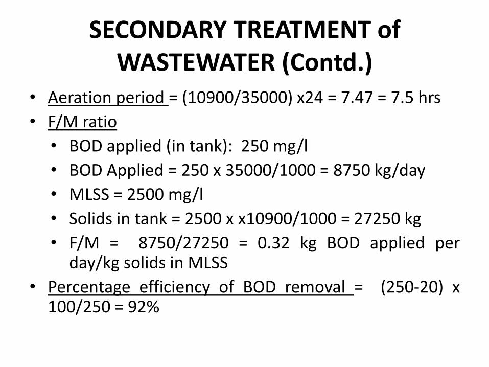
SECONDARY TREATMENT of WASTEWATER (Contd.) • Aeration period = (10900/35000) x24 = 7.47 = 7.5 hrs • F/M ratio • BOD applied (in tank): 250 mg/l • BOD Applied = 250 x 35000/1000 = 8750 kg/day • MLSS = 2500 mg/l • Solids in tank = 2500 x x10900/1000 = 27250 kg • F/M = 8750/27250 = 0.32 kg BOD applied per day/kg solids in MLSS • Percentage efficiency of BOD removal = (250-20) x 100/250 = 92%
Transcript of SECONDARY TREATMENT of WASTEWATER (Contd.)
SECONDARY TREATMENT of WASTEWATER (Contd.)
• Aeration period = (10900/35000) x24 = 7.47 = 7.5 hrs
• F/M ratio
• BOD applied (in tank): 250 mg/l
• BOD Applied = 250 x 35000/1000 = 8750 kg/day
• MLSS = 2500 mg/l
• Solids in tank = 2500 x x10900/1000 = 27250 kg
• F/M = 8750/27250 = 0.32 kg BOD applied per day/kg solids in MLSS
• Percentage efficiency of BOD removal = (250-20) x 100/250 = 92%

SECONDARY TREATMENT of WASTEWATER (Contd.)
• Sludge age:
• =
• = 8.58 days

SECONDARY TREATMENT of WASTEWATER (Contd.)
Secondary Clarifier • A secondary clarifier is used for settling the effluents from TF or ASP in a
similar way as primary settling tanks. • Like primary clarifiers they are also ordinarily rectangular or circular tanks. • DT of 1.5 -2.0 hrs and depths are generally kept between 3-4.5 m • The sludges settled at the bottom should be frequently removed and sent
to digestion tanks. • Since the sludges obtained from TF are well nitrified, the solid are bulkier
and dense, clarifiers are designed for an SOR of 40-70 m3/m2/day, whereas Clarifiers for ASP are designed at a lower SOR ranging from 20-40 m3/m2/day.
• Weir loading of around 185 m3/m/day is ok for TF clarifiers, whereas for ASP clarifiers it is preferable to keep it below 100, since the sludge particles are lighter and flocculent.
• ASP clarifiers are designed for sewage flow plus return sludge flows. They are generally not to exceed a solids loading rate of 100 kg/day/m2

SECONDARY TREATMENT of WASTEWATER (Contd.)
Design Problem: • A plant is treating 1250 m3/day of domestic sewage
using an ASP. The design feature for ASP state that MLSS concentration shall be 3000 mg/l with a return sludge rate of 50%. Design a secondary clarifier.
• Solution Average flow = 1250 m3/day Return flow = 625 m3/day Total flow = 1875 m3/day Provide a DT of 2hrs Volume of SST = 1873 x 2/24 = 156.25 m3

SECONDARY TREATMENT of WASTEWATER (Contd.)
Assume a depth of 3m Area of SST = 156.25/3 = 52.1 m2 Assume an SOR of 20 m3/m2/day Area of tank = 1875/20 = 92.5 m2 Provide greater area of 92.5 m2 Diameter = 10.8 m, provide 11m dia tank. Actual area provided 95 m2 Weir loading rate = 1875/(3.14x 11) = 54.3 m3/m/day (OK) Solids inflow in to tank = 1875 x 3000/1000 = 5625 kg/day Solids load = 5625/95 = 59.25 kg/day/m2, less than 100 hence ok Provide a clarifier of 11 m dia, 3m effective depth, bottom slope 1 in
12 Free board shall be 0.3m

SEPTIC TANKS and SOAKAGE PIT
Septic Tank
• A septic tank may be perceived as a primary settling tank with a longer detention period (12-36hr, as against a period of 2hrs in an ordinary sedimentation tank) with extra provision for sludge storage.
• A septic tank is thus a horizontal continuous flow type of sedimentation tank, directly admitting raw sewage and removing 60-70% of suspended solids.
• The sludge settled at the bottom and oil and grease rising to the top are allowed to remain in the tank for a period of several months, during which they are decomposed by anaerobic bacteria. Foul gases are produced, and as such, a septic tank will be a completely covered tank, and provided with high shaft for escape of gases.

SEPTIC TANKS and SOAKAGE PIT (Contd.)
• The resultant sludge so obtained will consequently be much less than that obtained in ordinary primary clarifier (the quantity is reduced by digestion). The digested sludge is periodically removed, once in six months (not later than 3 years), taken to a far off place, sun dried and then disposed of after burying or can be also used as a manure.
• After solids settle in the septic tank, the liquid wastewater (or effluent) is discharged to the soakage pit where they are treated by soil bacteria before finally meeting the ground water reserve.
• Households that are not served by public sewers usually depend on septic systems to treat and dispose of wastewaters. Septic tanks also serve isolated communities, schools, hospitals, and other public institutions.

SEPTIC TANKS and SOAKAGE PIT (Contd.)
• The tank is usually made underground It is designed to prevent direct current between the inflow and outflow which is achieved by using pipe tees with submerged end at inlet and outlets. These pipes also prevent escape of floating oil and grease in the effluent.
• Manhole cover is provided for inspection and withdrawal of sludge.
• Capacity of the tank should be enough to store wastewaters for one day plus the sludge for 6-months to a year. Normal sludge deposit may be assumed in the range of 25-40 liters/capita/year.
• A fee board of about 0.3m is provided at top. The depth of the tank varies from 1.2m – 1.8 m, and L/B ratio is generally 2-3.
• Septic tanks and soakage pits are safe methods of treatment and disposal of domestic wastewaters.

SEPTIC TANKS and SOAKAGE PIT (Contd.)
Soakage Pit • A soakage pit is a circular covered pit (usually 1-1.5 m dia
and similar depth) through which the effluent is allowed to be soaked in to the ground.
• The soakage pit may be filled with stone aggregates of 15-20mm size. In this case a top masonry ring is constructed to prevent damage of the pit due to flooding by surface runoff.
• If the pit can also be kept empty. In this case the pit is lined with brick, concrete blocks with dry open joints. In addition to this the lining is supported below the inlet level by at lease 7.5 cm thick backing of coarse aggregate. The lining above the inlet should be plastered with cement mortar.

SEPTIC TANKS and SOAKAGE PIT (Contd.)
Maintenance Tips • Disposal of chemical or excess organic matter, such as that from a
garbage disposal, can destroy a septic system. • Excessive water is a major cause of system failure. The soil under
the septic system must absorb all of the water used in the home. Too much water from laundry, dishwasher, toilets, baths, and showers may not allow enough time for sludge and scum to separate. The less water used, the less water entering the septic system, resulting in less risk of system failure.
• Keep household chemicals out of your septic system, such as caustic drain openers, paints, pesticides, photographic chemicals, brake fluid, gasoline, and motor oil. Improper disposal of toxic chemicals down the drain is harmful to the bacteria needed to break down wastes in the septic system.

SECONDARY TREATMENT of WASTEWATER (Contd.)
Septic Tank and Soakage Pit (Contd.)
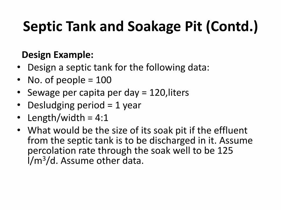
Design Example: • Design a septic tank for the following data: • No. of people = 100 • Sewage per capita per day = 120,liters • Desludging period = 1 year • Length/width = 4:1 • What would be the size of its soak pit if the effluent
from the septic tank is to be discharged in it. Assume percolation rate through the soak well to be 125 l/m3/d. Assume other data.

SEPTIC TANKS and SOAKAGE PIT (Contd.)
Design of Septic Tank Quantity of sewage per day = 12000 liters Assume the rate of sludge deposit as = 30 liters/capita/year Sludge volume = 3000 liters Total tank capacity = 15000 liters Assume DT of one day, volume of tank = 15 m3 Assume depth = 1.5 m Area of tank = 10 m2 Use L/B as 4, 4B2 = 10, L = 6.3 and B = 1.6 approx. The dimensions of the tank shall be 6.3 x 1.6 x 1.8 deep
including 0.3m free board.

SEPTIC TANKS and SOAKAGE PIT (Contd.)
Design of soak pit
Sewage outflow = 12000 l/day
Percolation rate = 1250 L/m3/day
Volume of soak pit = 12000/1250 = 9.6 m3
Keep the depth of soak pit as 2m
Area of pit = 4.8 m2
Which gives dia of soak pit as 2.5 m

UNIT TWO
• TREATMENT OF WATER

IMPURITIES IN WATER
• Raw water from different sources may have impurities of various kinds which render them unfit for a specific end use.
Very broadly the impurities may be: • Free floating matter: Wooden sticks, leaves, dead small animals; broken plastics,
cigarette ends, mixed clothes, rags etc. these would make water look athletically unacceptable. These are removed by means of Screens.

IMPURITIES IN WATER (Contd.)
• Finely divided organic or inorganic material Sand, silt and clay. Those may come into water as a result of
its contact with different land forms, discharge of effluents into streams which would make water look muddy; colored, possess unwanted tastes, odors, hardness, and/or make it unfit for a given end use. These are removed by settling and filtration
• Micro-organisms These come in water as result of contact with human and
animal wastes and soils. These render water unsafe for human consumption, and are removed by disinfection.

MUNICIPAL TREATMENT OF WATER
• At municipal treatment plant a number of units are arranged in sequence as shown below:

BROAD FUNCTIONS OF WATER TREATMENT UNITS
Screens • Removal of floating materials like dead animals,
insects, branches, pieces of rags, wood, leaves, torn clothes, broken plastics, and other large size floating matters. (NOT IN COURSE)
Primary Clarifier • Removal of heavy settle-able inorganic materials e.g.
sand, silt etc. Coagulation and flocculation • To convert very fine (colloidal) suspended impurities in
water in to large size flocs which can then be removed by settling in reasonable time.

BROAD FUNCTIONS OF WATER TREATMENT UNITS (Contd.)
Secondary Sedimentation • To separate large size flocculated impurities from
water by mere action of gravity. Filtration • To remove very fine suspended impurities from
water and also partial removal of pathogenic microbes
Disinfection • To kill all forms of bio-life in water that may cause
diseases to human beings.

Functions of Water Treatment Units
Unit treatment Function (removal):
• Aeration, chemicals use Color, Odor, Taste • Screening Floating matter • Chemical methods Iron, Manganese, etc. • Softening Hardness • Sedimentation Suspended matter • Coagulation Colloidal matter and bacteria • Filtration Remaining colloidal dissolved matter • Disinfection Pathogenic bacteria, Organic matter

SEDIMENTATION
• Sedimentation tanks (settling tanks, settling basins or clarifiers) are used to separate the settle-able suspended solids from water.
• When the impurities are separated from the water by the action of natural forces alone i.e. by gravitation the operation is called plain sedimentation.
• Sedimentation of water can be also be aided by chemicals (coagulants) that renders finer particles to settle by the action of coagulation and flocculation. This process is called chemically aided settling or secondary settling.
• In Plain settling particle of size up to 5 micron are removed.
SEDIMENTATION (Contd.)
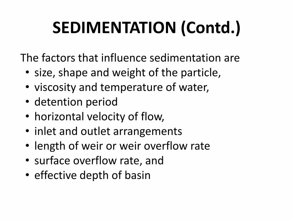
The factors that influence sedimentation are • size, shape and weight of the particle, • viscosity and temperature of water, • detention period • horizontal velocity of flow, • inlet and outlet arrangements • length of weir or weir overflow rate • surface overflow rate, and • effective depth of basin

SEDIMENTATION (Contd.)
• Settling velocity of discrete particle is defined by Stoke’s law as:
• Where :
• Vs is the vertical settling velocity, g is the acceleration due to gravity, ρs is
the density of particle, ρw is the density of water, d is the diameter of the particle, and μ is the dynamic viscosity of water.
• At 20oC, the dynamic viscosity is 1.002 x 10⁻³N.s/m2
SEDIMENTATION (Contd.)
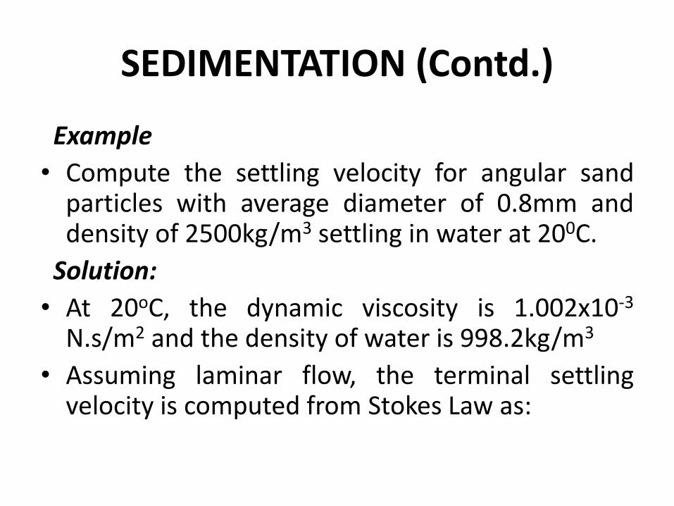
Example
• Compute the settling velocity for angular sand particles with average diameter of 0.8mm and density of 2500kg/m3 settling in water at 200C.
Solution:
• At 20oC, the dynamic viscosity is 1.002x10⁻³ N.s/m2 and the density of water is 998.2kg/m3
• Assuming laminar flow, the terminal settling velocity is computed from Stokes Law as:

SEDIMENTATION (Contd.)

Types of Sedimentation Tanks
Rectangular

Types of Sedimentation Tanks
Circular

SEDIMENTATION (Contd.)
• Rectangular flow tanks have horizontal flow and circular have radial flows.
• In rectangular tanks with horizontal flow the sludge is mechanically scraped to the influent end and then to a sump without disrupting the operation of the tank.
• In circular tank with radial flow, the sludge is mechanically scraped continuously to a central sump and withdrawn periodically.
• Tanks vary in depth from 2.5 to 4.0m, usually 3m

SEDIMENTATION (Contd.)
• For plain settling tanks the detention time varies from 3 to 4 hours, while for coagulated water it would be between 2 to 2.5 hours.
• Rectangular tanks to have the length three to four times the width. Lengths up to 30 m are common.
• Circular tanks up to 60 m in diameter are in use in the country though larger size tanks could be adopted.
• The surface loading used varies from 15 to 20 m3/d/m2
for plain tanks and 30-40 for coagulated tanks.

SEDIMENTATION (Contd.)
• Normal-weir loadings are up to 300 m3/d/m. But when settling tanks are properly designed, well clarified waters can be obtained at weir loadings of even up to 1500 m3/d/m.
• The average flow-through velocity in horizontal flow rectangular tanks is normally kept between 0.5 and 1.5 cm/sec. Weirs, are generally used as outlets.
• A well designed tank should be capable of having an efficiency of at least 70%, and should be capable of giving settled water having turbidity not exceeding 20 and preferably 5 NTU.

SEDIMENTATION (Contd.)
• Sedimentation Tank Design
• Problem: Design a rectangular sedimentation tank to treat 2.4 million liters of raw water per day. The detention period may be assumed to be 3 hours.
• Solution: Raw water flow per day is 2.4 x 10⁶ l. Detention period is 3h. • Volume of tank = Flow x Detention period = 2.4 x 103 x 3/24 = 300 m3 • Assume depth of tank = 3.0 m. • Surface area = 300/3 = 100 m2 • L/B = 3 (assumed). L = 3B. • 3B2 = 100 m2 i.e. B = 5.8 m • L = 3B = 5.8 X 3 = 17.4 m • Hence surface loading (Overflow rate) = 2.4 x 106 = 24,000 l/d/m2 < 40,000 • Check for weir overflow rate also.
100

Coagulation and Flocculation
General Properties of Colloids • Colloidal particles are very small (0.001mm) and their surface
area in relation to mass is very large. • Electrical properties: All colloidal particles are electrically
negatively charged. • Colloidal particles are in constant motion because like
charges repel each other. This motion is called Brownian motion.
• Colloidal particles are difficult to separate from water because they do not settle by gravity because of their size. Also they are in some kind of turbulence due to Brownian motion.
• To be removed, the individual colloids must aggregate and grow in size.

Coagulation and Flocculation Contd.
• Coagulation is the process by which a coagulant (chemical, usually salts of Al(III) and Fe(III) are commonly used as coagulants in water) is rapidly and uniformly dispersed through the mass of water. The chemical releases extra positive ions in water and destabilizes the charge on colloids. The detention period is 30 to 60 seconds and the head loss is 20 to 60 cms of water. Rapid or brisk mixing for dispersal of chemical (80-100 RPM) is necessary.
• Flocculation is essentially slow mixing (20 RPM for about 20-30 min) is provided either by baffles or paddles which promote agglomeration of particles. The slow mixing brings the contacts between the finely divided destabilized matter formed during rapid mixing.
• Coagulation and flocculation may or may not be followed by secondary settling.

Coagulation and Flocculation Contd.
Jar Test • The jar test is a common laboratory procedure used to
determine the optimum coagulant dose for a given turbidity.
• The jar testing apparatus consists of six paddles which stir the contents of six 1 liter containers. A rpm gage at the top-center of the device allows for the uniform control of the mixing speed in all of the containers. The alum dose in increment is added and the dose that gives best floc formation is noted down. The experiment may be repeated to narrow down the optimum dose value.

WATER FILTRATION
Filtration
• The resultant water after sedimentation will not be pure, and may contain some very fine suspended particles and bacteria in it.
• To remove or to reduce the remaining impurities still further, the water is filtered through the beds of fine granular material, such as sand, etc.
• The process of passing the water through the beds of such granular materials is known as Filtration.
• Filtration removes color, odor, turbidity and pathogenic bacteria from water.

Mechanism of filtration
Mechanical straining: Removal of particles because they are smaller than the voids in the filter beds.
Sedimentation: The voids spaces act as tiny settling tanks and provide calmer condition for settling particles of even smaller sizes than void spaces.
Biological metabolism: The voids contain tiny bacteria and other microbes which act on organic impurities in water and purify them.
Electrolytic charge: Impurities also get removed because the sand grains and impurities possess opposite charge.

Types of Filter
• Slow sand filter: They consist of an open air tank containing fine sand, supported by gravel. They capture particles near the surface of the bed and are usually cleaned by scraping away the top layer of sand that contains the particles.
• Rapid-sand filter: They consist of open air tank containing larger sand grains supported by gravel and capture particles throughout the bed. They are cleaned by backwashing water through the bed to 'lift out' the particles.
• Pressure Filter: They are much like small size pressure filter in a closed tank. The water is passed under pressure. Rate of filtration is much higher.
Principles of Slow Sand Filtration
• In a slow sand filter impurities in the water are removed by a combination of processes: sedimentation, straining, adsorption, and chemical and bacteriological action.
• During the first few days, water is purified mainly by mechanical and physical-chemical processes. The resulting accumulation of sediment and organic matter forms a thin layer on the sand surface, which remains permeable and retains particles even smaller than the spaces between the sand grains.
• As this layer (referred to as “Schmutzdecke”) develops, it becomes living quarters of vast numbers of micro-organisms which break down organic material retained from the water, converting it into water, carbon dioxide and other oxides.

Principles of Slow Sand Filtration Contd.
• Most impurities, including bacteria and viruses, are removed from the raw water as it passes through the filter top and the layer of filter bed sand just below. The purification mechanisms extend from the filter top to approx. 0.3-0.4 m below the surface of the filter bed, gradually decreasing in activity at lower levels as the water becomes purified and contains less organic material.
• When the micro-organisms become well established, the filter will work efficiently and produce high quality effluent which is virtually free of disease carrying organisms and biodegradable organic matter.
• They are suitable for treating waters with low colors, low turbidities (up to 50 ppm only) and low bacterial contents and hence influent water should not be coagulated.
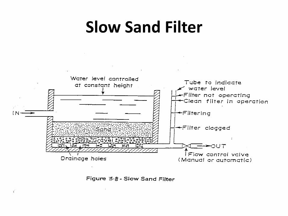
Slow Sand Filter

Rapid Sand Filter Working:
Open 1 and 4 and close all others
Backwash:
Close 1 and 5 and open 5 for a few minutes
Restart
Close 6 - Open 1, close 2 – open 3
Normal
Open 1 and 4, close all the rest

Slow Sand Filters vs. Rapid Sand Filters
• Base material: In SSF it varies from 3 to 65 mm in size and 30 to 75
cm in depth while in RSF it varies from 3 to 40 mm in size and its depth is slightly more, i.e. about 60 to 90 cm.
• Filter sand: In SSF the effective size ranges between 0.2 to 0.4 mm and uniformity coefficient between 1.8 to 2.5 or 3.0. In RSF the effective size ranges between 0.35 to 0.55 and uniformity coefficient between 1.2 to 1.8. The depth of sand is 90-110 cm in SSF and 60-90 cm in RSF.
• Rate of filtration: In SSF it is small, such as 100 to 200 L/h/sq.m of filter area while in RSF it is large, such as 3000 to 6000 L/h/sq.m of filter area.
• Efficiency: SSF removes 98-99% bacteria but less efficient in color removal, whereas RSF can remove only 80-90% bacteria, and can handle vey turbid water after coagulation and flocculation.

Slow Sand Filters vs. Rapid Sand Filters Contd.
• Period of cleaning: SSF are cleaned once in 1-3 month, whereas RSF are cleaned once a day
• Flexibility: SSF are not flexible for meeting variation in demand whereas RSF are quite flexible for meeting reasonable variations in demand.
• Post treatment required: Almost pure water is obtained from SSF. However, water may be disinfected slightly to make it completely safe. Disinfection is a must after RSF.
• Method of cleaning: Scrapping and removing of the top 1.5 to 3 cm thick layer is done to clean SSF. To clean RSF, sand is agitated with air and backwashed with water.
• Loss of head: In case of SSF approx. 10 cm is the initial loss, and 0.8 to 1.2m is the final limit when cleaning is required. For RSF 0.3m is the initial loss, and 2.5 to 3.5m is the final limit when cleaning is required.

Pressure Filter
• These are closed steel tanks. The diameter varies from 1.5 – 3.0 m and length 3.5- 8 m.
• The water entering is coagulated and the flocculation and sedimentation takes place inside the tank during passage of water.
• The cleaning is carried out by back washing. • The rate of filtration is 6000-15000 l/hr/m2 of the
area. Filter is less efficient than rapid sand filter. • They are not used for municipal w/s but are
useful for small colonies, swimming pools, industries and railway stations etc.

Disinfection
• The filtered water may normally contain some harmful disease producing
bacteria in it. These bacteria must be killed in order to make the water safe for drinking. The process of killing these bacteria is known as Disinfection.
• Methods of Disinfection • Boiling: The bacteria present in water can be destroyed by boiling it for a
long time. However it is not practically possible to boil huge amounts of water. At treatment plant. Moreover it cannot take care of future possible contaminations. Generally practiced in epidemics at home level.
• Treatment with Ozone: Ozone readily breaks down into normal oxygen, and releases nascent oxygen. The nascent oxygen is a powerful oxidizing agent and removes the organic matter as well as the bacteria from the water. However ozone has no residual effect. This method also requires huge capital expense and is power dependent.
• UV rays: Water can be disinfected by passing UV rays. However the water should not have any turbidity. This method is good for killing protozoa but is not very effective for bacteria kill.

Chlorination
• It is the application of chlorine to water for killing pathogenic bacteria. Chlorine is a strong oxidizing agent and oxidizes the cell wall which is essentially the organic matter and the cells become inactivated. Chlorine can be applied to water in solid, liquid and gaseous forms. Chlorine also reacts with ammonia, sulphur, iron and manganese and other compounds present in water.
• Chlorine Chemistry Chlorine is added to the water supply in two ways. It is
most often added as a gas, Cl2(g). However, it also can be added as a salt, such as sodium hypochlorite (NaOCl) or bleach. Chlorine gas dissolves and becomes aqueous in water.

Cl2(g) Cl2(aq)
Once dissolved, the following reaction occurs forming hypochlorous acid (HOCl):
Cl2(aq) + H2O HOCl + H+ + Cl-
Hypochlorous acid is a weak acid that dissociates to form hypochlorite ion (OCl-).
HOCl OCl- + H+ All forms of chlorine are measured as mg/L of Cl2 (MW = 2 x 35.45 = 70.9
g/mol)

Chlorination Contd.
• Hypochlorous acid and hypochlorite ion compose what is called the free chlorine residual. These free chlorine compounds can react with many organic and inorganic compounds to form chlorinated compounds. A common compound in drinking water systems that reacts with chlorine to form combined residual Chlorine is ammonia.
• Reactions between ammonia and chlorine form chloramines, which is mainly monochloramine (NH2Cl), although some dichloramine (NHCl2) and trichloramine (NCl3) also can form. If excess free chlorine exits once all ammonia nitrogen has been converted to chloramine then bacterial species are oxidized through what is termed the breakpoint reactions.

Estimation of Chlorine dose
• Breakpoint Reaction: (Draw graph) When Chlorine is added to water it combines with ammonia to form different forms of amines. In this phase the residual chlorine is much less that the applied chlorine. After a while when all ammonia gets oxidized – and the residual concentration builds up, the free chlorine is used to disinfect the pathogens. In this phase the residual chlorine decreases even though the dosage is being increasingly applied. There comes a point when disinfection is complete. This is called the break point value. After which residual chlorine and applied chlorine follow a 45 degree line. The dose of chlorine should be at least 0.1 mg/l more than the breakpoint value to take care of future contamination.

Color, odor taste, fluoride and hardness removal
• Conventional treatment units do not remove color which is caused by the of presence of iron and manganese, algae; or odor and bad taste from water which results because of the presence of dissolved gases ( H2S, CO2), phenolic and other organic compounds. Further presence of excess fluorides causes fluorosis and need also be removed. Further if the water is hard because of the presence of bicarbonates, carbonates, sulphates or chlorides of Ca and Mg these also need be removed prior to distribution to community.
• Color, odor and taste removal: • Some of the methods that are commonly adopted are: Aeration,
use of oxidizing agents, treatment with copper sulphate, and filtering through a bed of activated carbon.

Color, Odor and Taste Removal
• Aeration: • Water containing excessive amounts of iron and
manganese can stain clothes, discolor plumbing fixtures, and sometimes add a “rusty” taste and look to the water. Aeration is best practice used to remove them. Aeration provides the dissolved oxygen needed to convert the iron and manganese from their ferrous and manganous forms to their insoluble oxidized ferric and manganic forms. It takes 0.14 ppm of dissolved oxygen to oxidize 1 ppm of iron; it takes 0.27 ppm of dissolved oxygen to oxidize 1 ppm of manganese. The process requires careful control of aeration because if less aeration is provided the job is not done, and more of it causes excess DO which may make water corrosive.

Color, Odor and Taste Removal Contd.
• Aeration is best provided (a) by passing the water to fall over a series of steps of 0.2-0.3 m high, (b) by bubbling air through perforated pipes placed at the bottom of water tank, © by ejecting water though nozzles so it entraps air from atmosphere, (d) passing water over a bed of rocks (much like trickling filter) which is arranged in a series of trays of about 0.6 m deep and separated by 0.45m of clear space in between them. Aeration not only oxidizes chemical compounds but also drives away dissolved gases that cause bad taste and odor. However the water must be sedimented to remove the iron and manganese precipitates.

Color, Odor and Taste Removal Contd.
• Use of Oxidizing agents: • Oxidizing agents normally used are chlorine, potassium
permanganate, and ozone. Chlorine gas helps also removing bad taste and odor by oxidizing organic matter, but then the dosage should be over and above breakpoint value. Dosage of potassium permanganate of 0.005-0.1 mg/l can be used. Ozone is normally not used in India because of high costs.
• Use of Copper Sulphate: • This is principally used to kill algae and associated
hazards of color resulting from them. A dosage of 0.5 -0.75 mg/l is applied in service/distribution reservoirs

Fluoridation and Defluoridation of Water
• When fluorides concentration in water is less than 1 mg/l, it causes dental cavities and fluorides are added to water and the process is called fluoridation. However, if fluorides are in excess of 1.5 mg/l, it causes fluorosis and excess fluoride has to be removed from water and the process is called defluoridation.
• Fluoridation of water supplies is carried out using chemical compounds e.g. Sodium fluoride (NaF), or sodium silico fluoride (Na2 SiF6) or hydro-fluosilicic acid (H2SiF6). These chemicals are water soluble, so a concentrated solution of any one of them is fed at a regulated dose in public water supplies. Most commonly used compound in India is Sodium fluoride.

Fluoridation and Defluoridation of Water Contd.
• When drinking water contains fluorides in excess of 1.5 mg/l, it causes fluorosis, which is characterized by blacked or mottled (stained ) teeth. Excess fluorides can also cause neurological disorders and gastro-intestinal diseases, and can be symptomed as neck, spine, knee and shoulder pains, diarrhea, nervousness and excess thirst. Excess fluoride is a big problem in Andhra specially in Nalgonda and Ananthapur district.
• Defluoridation can be achieved by one or the other below mentioned techniques:
• Adsorption by Activated Alumina: It is developed by Satya Sai University of Andhra Pradesh and costs Rs 35000/- at community or Rs 1700/- at household level. Recurring cost is replacement/regeneration of bed media. Filters can be attached with and pumps, or stand-posts. Though it is a good technique, regeneration of bed or after sales service is poor.

Defluoridation of Water Contd.
• Nalgonda Technique: • Developed by NEERI in 1975.In this process alum and lime
are added to water and stirred for 10 min. Fluorides get adsorbed by alum and flocks get formed. These are settled for 1.5 hrs . The water is then filtered. It is low in capital cost and can be used at household and community level. It requires careful regulation of dosages and settlement of flocs can be an issue at times.
• Ion Exchange Method: • This is developed by Ion Exchange, India. Its capacity is
flexible from 500-5000 liters/hr. It is very effective and can be used again at community and household level. Regeneration of resin is an issue.

Water Softening
• Hard water taste is unacceptable to public. These also cause deposits in plumbing fixtures, and cause more consumption of soap. So when hardness is more than 300 mg/l it needs to be removed from public w/s. The process of the removal of hardness from water is called softening of water.
• Water need be softened for industry use because it would otherwise cause scaling of boilers and may interfere with dyeing operation.
• Hardness is basically of two types: temporary (carbonate) hardness which is caused by carbonates and bicarbonates of calcium and magnesium, and permanent hardness which is caused by chlorides, nitrates and sulphates of Ca, Mg.

Water Softening Contd.
• Removal of temporary hardness: It can be removed by the following methods,
• (a) By boiling : During boiling, the bicarbonates of Ca and Mg decompose into insoluble carbonates and give CO2. The insoluble carbonates can be removed by filtration.
Heat • Ca(HCO3)2 —————→ CaCO3 + CO2 + H2O Cal. bicarbonate PPt Heat Mg(HCO3)2 —————→ MgCO3 + CO2 + H2O Mag. bicarbonate PPt
Water Softening Contd.
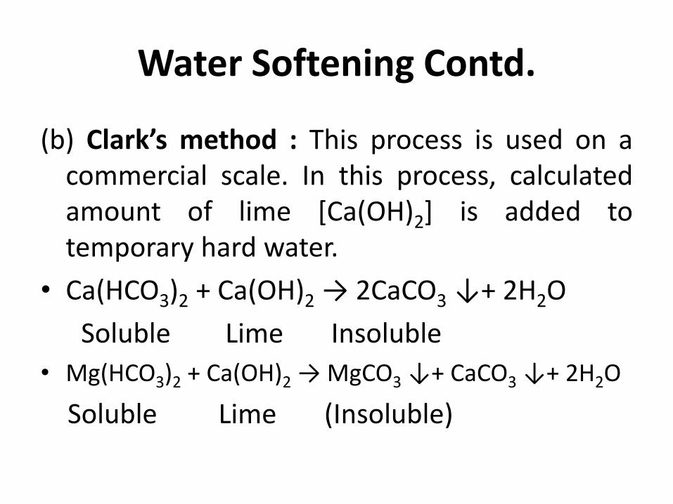
(b) Clark’s method : This process is used on a commercial scale. In this process, calculated amount of lime [Ca(OH)2] is added to temporary hard water.
• Ca(HCO3)2 + Ca(OH)2 → 2CaCO3 ↓+ 2H2O
Soluble Lime Insoluble
• Mg(HCO3)2 + Ca(OH)2 → MgCO3 ↓+ CaCO3 ↓+ 2H2O
Soluble Lime (Insoluble)

Water Softening Contd.
Removal of permanent hardness: Permanent hardness can be removed by the following methods:
(a) By washing soda method: In this method, water is treated
with a calculated amount of washing soda (Na2CO3) which converts the chlorides and sulphates of Ca and Mg into their respective carbonates which get precipitated.
• CaCl2 + Na2CO3 → CaCO3 + 2NaCl ppt.
• MgSO4 + Na2CO3 → MgCO3 + Na2SO4 ppt.
Water Softening Contd.
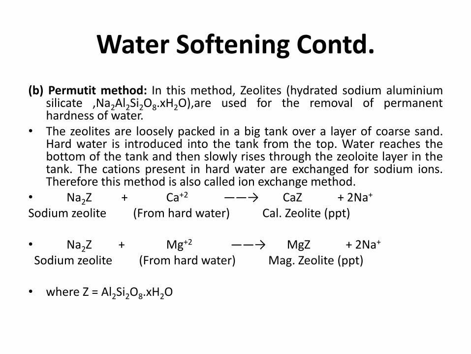
(b) Permutit method: In this method, Zeolites (hydrated sodium aluminium silicate ,Na2Al2Si2O8.xH2O),are used for the removal of permanent hardness of water.
• The zeolites are loosely packed in a big tank over a layer of coarse sand. Hard water is introduced into the tank from the top. Water reaches the bottom of the tank and then slowly rises through the zeoloite layer in the tank. The cations present in hard water are exchanged for sodium ions. Therefore this method is also called ion exchange method.
• Na2Z + Ca+2 ——→ CaZ + 2Na+ Sodium zeolite (From hard water) Cal. Zeolite (ppt) • Na2Z + Mg+2 ——→ MgZ + 2Na+ Sodium zeolite (From hard water) Mag. Zeolite (ppt) • where Z = Al2Si2O8.xH2O