Secondary System Analysis · Secondary System Analysis 2005 Stray Voltage Detection and ......
229
. . . . . . . . . . . . . . . . . . . . Distribution Engineering Secondary System Analysis 2005 Stray Voltage Detection and Electric Facility Inspection Report Leo A. Scally 4 Irving Place – Room 1138 NY, NY 10003
Transcript of Secondary System Analysis · Secondary System Analysis 2005 Stray Voltage Detection and ......

. . . . . .. . . .
. . . . . . . . . .
Distribution Engineering
Secondary System Analysis
2005 Stray Voltage Detection and Electric Facility Inspection Report
Leo A. Scally 4 Irving Place – Room 1138 NY, NY 10003
. . . . . . .. . .
2
Con Edison 2005 Stray Voltage Detection and Electric Facility Inspection Report
Table of Contents
Table of Contents...................................................................................................................................2 Introduction ............................................................................................................................................8 Overview of Con Edison’s Electric System.........................................................................................9
Distribution..........................................................................................................................................9 Underground..................................................................................................................................9 Overhead.......................................................................................................................................9 Streetlights.....................................................................................................................................9
Transmission ....................................................................................................................................10 Underground................................................................................................................................10 Overhead.....................................................................................................................................10
Substations .......................................................................................................................................10 Unit Substations................................................................................................................................10
PART ONE – 2005 STRAY VOLTAGE TESTING PROGRAM.................11 Introduction ..........................................................................................................................................12
Distribution........................................................................................................................................12 Substations and Transmission .........................................................................................................12 Repairs..............................................................................................................................................12 Quality Assurance.............................................................................................................................13
Stray Voltage Testing Of Underground Distribution Structures Including Underground Residential Distribution (URD) ...........................................................................................................14
Scope................................................................................................................................................14 Overall Program................................................................................................................................14 Stray Voltage Test Procedure ..........................................................................................................15
EO-5100 (Low Voltage Detectors - Stray Voltage) .....................................................................15 EO-100175 (Purchase Recommendation - Low Voltage Detectors For Stray Voltage) .............15 EO-10129 (Operation And Maintenance Of Low Voltage Detector For Stray Voltage) ..............15 B-63 (Stray Voltage Testing Of Company Structures And Streetlights)......................................15 EO-10358 (Annual Contractor Stray Voltage Inspection Procedure)..........................................15 EO-10360 (Troubleshooting of Streetlights)................................................................................15
Training.............................................................................................................................................15 Company Employees ..................................................................................................................15 Contractors ..................................................................................................................................16
Results ..............................................................................................................................................16 Quality Assurance Measures Instituted ............................................................................................17
3
UG Random Quality Assurance Audits .......................................................................................17 Work-in-Progress Audits..............................................................................................................17
Additional Quality Assurance Measures Instituted ...........................................................................17 New Structures Mapped in 2005 .................................................................................................17 New Structures Unmapped in 2005 ............................................................................................17 Structures With No Access..........................................................................................................18
No Access – Construction/Dumpster .....................................................................................18 No Access – Private Property (Locked Fence or Gate) .........................................................18 No Access – Highway ............................................................................................................18 No Access – Con Ed Property ...............................................................................................18 No Access – Inside Building...................................................................................................18 No Access – Buried Box ........................................................................................................18 No Access – Paved Over .......................................................................................................19
Not Found – Verified Data Error..................................................................................................19 Stray Voltage Testing Of Overhead Distribution Structures...........................................................20
Scope................................................................................................................................................20 Overall Program................................................................................................................................20 Stray Voltage Test Procedure ..........................................................................................................20
EO-5100 (Low Voltage Detectors - Stray Voltage) .....................................................................21 EO-100175 (Purchase Recommendation - Low Voltage Detectors For Stray Voltage) .............21 EO-10129 (Operation And Maintenance Of Low Voltage Detector For Stray Voltage) ..............21 B-63 (Stray Voltage Testing Of Company Structures And Streetlights)......................................21 EO-10358 (Annual Contractor Stray Voltage Inspection Procedure)..........................................21 EO-10360 (Troubleshooting of Streetlights)................................................................................21 Shunt Resistor .............................................................................................................................21
Training.............................................................................................................................................22 Company Employees ..................................................................................................................22 Contractors ..................................................................................................................................22
Results ..............................................................................................................................................22 Quality Assurance Measures Instituted ............................................................................................23
OH Random Quality Assurance Audits .......................................................................................23 Work-in-Progress Audits..............................................................................................................24
Additional Quality Assurance Measures Instituted ...........................................................................24 Fringe Plates ...............................................................................................................................24 No Access Poles .........................................................................................................................24
No Access – Residential (Rear Yard) ....................................................................................24 No Access – Commercial (Behind Locked Gate)...................................................................24 No Access – Con Edison Property.........................................................................................24 No Access – Railroad.............................................................................................................25 No Access – Construction......................................................................................................25
Not Found Poles..........................................................................................................................25 Zero Pole Plates ..........................................................................................................................25
Stray Voltage Testing Of Municipality Owned Streetlights .............................................................26 Scope................................................................................................................................................26 Overall Program................................................................................................................................26 Test Procedure .................................................................................................................................26
EO-5100 (Low Voltage Detectors - Stray Voltage) .....................................................................27 EO-100175 (Purchase Recommendation - Low Voltage Detectors For Stray Voltage) .............27 EO-10129 (Operation And Maintenance Of Low Voltage Detector For Stray Voltage) ..............27 B-63 (Stray Voltage Testing Of Company Structures And Streetlights)......................................27 EO-10358 (Annual Contractor Stray Voltage Inspection Procedure)..........................................27 EO-10360 (Troubleshooting of Streetlights)................................................................................27
Training.............................................................................................................................................27
. . . . . . .. . .
4
Results ..............................................................................................................................................28 Quality Assurance Measures Instituted ............................................................................................28
Random Quality Assurance Audits..............................................................................................29 Work-in-Progress.........................................................................................................................29
Additional Quality Assurance Measures Instituted ...........................................................................29 No Access Streetlights ................................................................................................................29
No Access - Construction.......................................................................................................29 No Access – Restricted Access .............................................................................................29
Verification of Streetlight Plates Tested ......................................................................................30 Plates with Mapped Streetlights.............................................................................................30 Plates without Mapped Streetlights........................................................................................30
Verification of DOT Repairs.........................................................................................................30 Stray Voltage Repairs.......................................................................................................................30
Stray Voltage Testing Of Overhead Transmission Facilities ..........................................................31 Scope................................................................................................................................................31 Overall Program................................................................................................................................31 Test Procedure .................................................................................................................................31
Shunt Resistor .............................................................................................................................31 Training.............................................................................................................................................31 Results ..............................................................................................................................................32 Quality Assurance Measures Instituted ............................................................................................32
Stray Voltage Testing Of Underground Transmission Facilities ....................................................33 Scope................................................................................................................................................33 Overall Program................................................................................................................................33 Test Procedure .................................................................................................................................33
EO-5100 (Low Voltage Detectors - Stray Voltage) .....................................................................33 EO-100175 (Purchase Recommendation - Low Voltage Detectors For Stray Voltage) .............33 EO-10129 (Operation And Maintenance Of Low Voltage Detector For Stray Voltage) ..............33 B-63 (Stray Voltage Testing Of Company Structures And Streetlights)......................................33 EO-10358 (Annual Contractor Stray Voltage Inspection Procedure)..........................................33
Training.............................................................................................................................................34 Company Employees ..................................................................................................................34 Contractors ..................................................................................................................................34
Results ..............................................................................................................................................34 Quality Assurance Measures............................................................................................................34
New Structures Unmapped in 2005 ............................................................................................34 Structures With No Access..........................................................................................................34
No Access – Private Property (Locked Fence or Gate) .........................................................35 No Access – Con Ed Property ...............................................................................................35
Stray Voltage Testing Of Substation Facilities.................................................................................36 Scope................................................................................................................................................36 Overall Program................................................................................................................................36 Test Procedure .................................................................................................................................36
EO-5100 (Low Voltage Detectors - Stray Voltage) .....................................................................36 EO-100175 (Purchase Recommendation - Low Voltage Detectors For Stray Voltage) .............37 EO-10129 (Operation And Maintenance Of Low Voltage Detector For Stray Voltage) ..............37
Training.............................................................................................................................................37 Results ..............................................................................................................................................37 Quality Assurance Measures............................................................................................................37
Stray Voltage Testing Of Unit Substation Facilities.........................................................................38 Scope................................................................................................................................................38 Overall Program................................................................................................................................38
5
Test Procedure .................................................................................................................................38 EO-5100 (Low Voltage Detectors - Stray Voltage) .....................................................................38 EO-100175 (Purchase Recommendation - Low Voltage Detectors For Stray Voltage) .............38 EO-10129 (Operation And Maintenance Of Low Voltage Detector For Stray Voltage) ..............38
Training.............................................................................................................................................38 Results ..............................................................................................................................................39 Quality Assurance Measures............................................................................................................39
PART TWO – ADDITIONAL STRAY VOLTAGE DETECTION.................41 Additional Stray Voltage Detection....................................................................................................42
Routine Work Stray Voltage Testing ................................................................................................42 Reports from the Public ....................................................................................................................42
PART THREE – 2005 FACILITY INSPECTION PROGRAM ....................43 Facility Inspection Procedures...........................................................................................................44
Introduction .......................................................................................................................................44 Facility Inspections Of Underground Distribution Structures Including URD ..............................45
Scope................................................................................................................................................45 Procedure .........................................................................................................................................45 Results ..............................................................................................................................................45
Tracking Inspections....................................................................................................................45 Repairs ........................................................................................................................................46
Quality Assurance Measures Instituted ............................................................................................46 Random Quality Assurance Audits – Underground Inspections .................................................47 Work in Progress – Underground Inspections ............................................................................47
Training.............................................................................................................................................47 Facility Inspections Of Overhead Distribution Structures ..............................................................48
Scope................................................................................................................................................48 Procedure .........................................................................................................................................48 Results ..............................................................................................................................................48
Tracking Inspections....................................................................................................................48 Repairs ........................................................................................................................................48
Quality Assurance Measures Instituted ............................................................................................48 Random Quality Assurance Audits – Overhead Inspections ......................................................49 Work in Progress – Overhead Inspections..................................................................................49
Training.............................................................................................................................................49 Overhead Transmission Facility Inspections ...................................................................................50
Scope................................................................................................................................................50 Procedure .........................................................................................................................................50 Results ..............................................................................................................................................50
Tracking Inspections....................................................................................................................50 Repairs ........................................................................................................................................50
Quality Assurance Measures Instituted ............................................................................................50 Training.............................................................................................................................................51
Underground Transmission Facility Inspections .............................................................................52 Scope................................................................................................................................................52 Procedure .........................................................................................................................................52 Results ..............................................................................................................................................52
Tracking Inspections....................................................................................................................52 Repairs ........................................................................................................................................53
. . . . . . .. . .
6
Quality Assurance Measures Instituted ............................................................................................53 Training.............................................................................................................................................53
Substation Facility Inspections..........................................................................................................54 Scope................................................................................................................................................54 Procedure .........................................................................................................................................54 Results ..............................................................................................................................................54
Tracking Inspections....................................................................................................................54 Repairs ........................................................................................................................................55
Quality Assurance Measures Instituted ............................................................................................55 Training.............................................................................................................................................55
Unit Substation Facility Inspections..................................................................................................56 Scope................................................................................................................................................56 Procedure .........................................................................................................................................56 Results ..............................................................................................................................................56
Tracking Inspections....................................................................................................................56 Repairs ........................................................................................................................................56
Quality Assurance Measures Instituted ............................................................................................56 Training.............................................................................................................................................56
PART FOUR – PUBLIC SERVICE COMMISSION PERFORMANCE MECHANISM.............................................................................................57
Public Service Commission Performance Mechanism....................................................................58 Stray Voltage Testing .......................................................................................................................58 Facility Inspections ...........................................................................................................................58
PART FIVE – CERTIFICATION OF STRAY VOLTAGE TESTING AND FACILITY INSPECTION PROGRAMS......................................................61
Certification of Stray Voltage Testing and Facility Inspection Programs......................................62
PART SIX – ANALYSIS OF STRAY VOLTAGE TESTING RESULTS.....63 Analysis of Stray Voltage Testing Results........................................................................................64
PART SEVEN – STRAY VOLTAGE INITIATIVES....................................65 Stray Voltage Initiatives ......................................................................................................................66
Research and Development .............................................................................................................66 Mobile Stray Voltage Detector.....................................................................................................66 Composite Covers .......................................................................................................................66 Manhole Cover Monitoring System .............................................................................................66 Arcing Signature ..........................................................................................................................66
PART EIGHT – FUTURE IMPROVEMENTS.............................................69 Future Improvements ..........................................................................................................................70
Shunt Resistor ..................................................................................................................................70 Visual Secondary Targeting (VST) ...................................................................................................70 Inspection System Development ......................................................................................................70 Data Management ............................................................................................................................71
7
APPENDIX.................................................................................................73 A: EO-5,100 (Low Voltage Detectors - Stray Voltage) ...............................................................75 B: EO-100,175 (Purchase Recommendation - Low Voltage Detectors For Stray Voltage) .......76 C: EO-10,129 (Operation And Maintenance Of Low Voltage Detector For Stray Voltage)........78 D: B-63 (Stray Voltage Testing Of Company Structures And Streetlights) ................................80 E: EO-10,358 (Annual Contractor Stray Voltage Inspection Procedure) ...................................82 F: EO-10,360 (Troubleshooting Of Streetlights).........................................................................84 G: Shunt Resistor Brochure ........................................................................................................85 H: Overhead Transmission Stray Voltage Testing Specification................................................87 I: Overhead Transmission Facility Inspection Specification......................................................89 J: Substations Stray Voltage Testing and Inspection Procedure...............................................91 K: EO-10,790 (Insp. & Maint. Schedule For 4 kV Unit & Multi-Bank SS Transf. & Switchgear .93 L: HD Test Reports.....................................................................................................................94 M: Corporate Safety Procedure 17.01 ........................................................................................95 N: EO-10,359 (Periodic Underground Distribution Structure Inspections) .................................96 O: Certification of Stray Voltage Testing.....................................................................................98 P: Certification of Inspections ...................................................................................................100

. . . . . . .. . .
8
Introduction
On January 5, 2005, the New York Public Service Commission (PSC) issued its “Order Instituting Safety Standards” in Case No 04-M-0159. The Safety Standards require that electric utilities annually test for stray voltage all of their publicly accessible transmission and distribution facilities and metallic pole streetlights and traffic signals located on public thoroughfares (“streetlights”). A full round of stray voltage testing is to be completed by November 30, each year. The Safety Standards also require that electric utilities visually inspect all of their electric facilities on a five-year cycle. Additional requirements of the Safety Standards include:
1. Guard all stray voltage detected locations until made safe irrespective of whether the positive stray voltage conditions are the responsibilities of the utility Company or non-utility party. Permanent repairs must be made within 45 days, except in extraordinary circumstances.
2. Analyze stray voltage conditions and causes, and develop measures to prevent occurrences.
3. Develop a quality assurance (QA) program to ensure timely and proper compliance with the Safety Standards.
4. Track and maintain records of inspection and stray voltage testing dates and results for every facility inspected and tested. Records must be readily accessible and searchable, continuously updated, and subject to PSC audit.
5. Certify the completion and results of inspections and stray voltage tests and that all unsafe conditions are remedied.
The Safety Standards establish annual voltage testing and inspection targets and include a performance mechanism to promote compliance with these targets. Failure to comply with the testing or inspection performance targets in any year will result in an earnings revenue adjustment equal to 75 basis points of return on common equity for each missed target.
This report describes Consolidated Edison of New York, Inc.’s (“Con Edison” or “the Company”) stray voltage detection program and equipment inspection program conducted in 2005 and addresses the following:
1. Results of the stray voltage testing program
2. Additional stray voltage detection
3. Results of the electrical facility inspection program
4. Adherence to PSC performance mechanism
5. Certification of stray voltage and inspection program
6. Analysis of results
7. Additional stray voltage related initiatives
8. Future improvements
9
Overview of Con Edison’s Electric System
Con Edison provides electricity in a 604-square mile encompassing New York City and most of Westchester County. Con Edison’s transmission and distribution systems provide a high level of reliability in a very dense urban environment. The transmission system is comprised of overhead and underground transmission feeders that transmit power from generating stations and transmission ties with neighboring utility systems to the Company substations. The distribution system is comprised of overhead and underground cables and transformers that deliver power from the Company’s substations to the Company’s 3.1 million electric customers.
Distribution The Con Edison electric distribution system, which is located in the five boroughs of New York City and most of Westchester County, covers 604 square miles. As of January 1, 2005, Con Edison served 3,161,384 electric customers: 2,319,321 network and 842,063 non-network. Approximately 86 percent of the 24,693,178 - kVA-distribution transformer capacity is underground, and 14 percent is overhead.
The distribution system is divided into four regions: Bronx/Westchester, Brooklyn/Queens, Manhattan, and Staten Island. There are 57 substations supplying 76 secondary networked and non-networked load areas. Stations are supplied through 267 miles of radial transmission feeders operating at 345 kV, 138 kV, or 69 kV. 1,998 distribution feeders, including 23 - 33 kV feeders, 309 - 27 kV feeders, 929 - 13 kV feeders, and 737 - 4 kV feeders, supply non-network and network load.
Underground Con Edison’s underground electric distribution system serves approximately 2.3 million of Con Edison’s 3.1 million electric customers via 57 secondary, alternating current (“AC”) networks. Each network is supplied by primary 27kV or 13.8 kV distribution feeders that connect to network transformers that reduce the voltage to 120/208 volts. Each of the 57 networks is laid out in a grid of underground, low voltage, insulated secondary cables. The insulation on the cables is rated at 600 volts and provides insulation protection that is several times greater than the operating 120/208 voltage of the secondary cables.
These low-voltage insulated cables travel, for the most part, through concrete or metal underground ducts beneath roadways and eventually enter manholes and service boxes. From there, low-voltage, insulated service cables run underground to the individual buildings and homes served by Con Edison. The underground system has approximately 274,000 manholes, service boxes, and transformer vaults; 23,201 conduit miles of underground duct; 34,155 underground transformers; and 91,112 miles of underground cable including primary, secondary, and service cables. (Service cables run from service boxes to customer facilities.) The secondary distribution system also supplies direct current (“DC) service in Manhattan through about 140 miles of DC service cable.
Overhead The overhead distribution system includes: 143 autoloops, seven 4 kV multi-bank and 218 - 4 kV unit substations, approximately 278,000 Con Edison or Verizon-owned poles, and 33,011 miles of overhead wires, including primary, secondary, and services. Cables operating at primary voltages of 33 kV, 27 kV, 13.8 kV, and 4 kV supply 46,246 overhead transformers that step the primary voltages down to 120/208/240v distribution voltages that are used by customers.
Streetlights Con Edison does not own, install, or maintain streetlights within its service territory. The New York City Department of Transportation (NYCDOT) and the local Westchester municipalities own the streetlights in New York City and Westchester respectively. There are approximately 173,000 publicly accessible metal pole streetlights in the Company’s service territory. Con Edison cables and structures directly supply approximately 119,000 of these streetlights. Municipally owned cables supply the remainder of the streetlights.
. . . . . . .. . .
10
Transmission The transmission system is comprised of overhead and underground transmission feeders that deliver power from generating stations and transmission ties with neighboring utilities to the Company’s substations.
Underground Con Edison’s underground transmission system is located in all five boroughs of New York City and in Westchester Counter, delivering power at 69kV, 138kV, and 345kV to various switching and substations. The system consists of more than 1,700 manholes and 600 circuit miles of cable. The cable system includes pipe-type cable, where cable is installed in pipes containing pressurized dielectric fluid, and solid dielectric cable, which is installed in concrete or fiberglass ducts or is direct buried.
Overhead The overhead transmission system consists of 138 kV and 345 kV high voltage cable supported on towers and poles on approximately 115 miles of right-of-way located for the most part north of New York City and terminating in Westchester County where the underground transmission system begins.
Substations Con Edison has 18 – 345kV switching substations that provide interconnection points for:
• The 345kV transmission system within Con Edison
• The 345kV inter-ties with other utilities
• Ties to major generating facilities
• Ties to the 138kV transmission system
Con Edison has 19 – 138kV switching substations, and 1 - 69 kV substation which provide interconnection points for:
• The 138kV transmission system within Con Edison
• The 138kV inter-ties with other utilities
• Ties to major generating facilities
• Ties to supply power to substations
Con Edison has 57 substations each of which directly supplies one or two distribution load areas. The primary voltages at these stations are 69 kV, 138 kV or 345 kV. The distribution level voltages are 13.8 kV, 27 kV or 33 kV, depending on the region. In summary, there are 38 transmission stations and 57 stations, located at 63 sites. (Some sites have more than one substation.)
In addition, there are 14 Public Utility Regulating Stations (PURS). These stations provide cooling/heat exchange for the pressurized dielectric fluid in underground pipe-type feeders.
Unit Substations There are 230 unit substations located throughout the Bronx, Brooklyn, Queens, Staten Island and Westchester in the Con Edison system. The unit substation power transformer converts primary 33 kV, 27 kV, and 13.8 kV to 4.33 kV. The 4 kV feeders that emanate from a unit station tie to 4 kV feeders from other unit substations to create a 4 kV grid system. The 4 kV grid system supplies approximately 10 % of Con Edison’s total load.
. . . . . .. . . .
. . . . . . . . . .
Part One – 2005 Stray Voltage Testing Program
2005 Stray Voltage Detection and Electric Facility Inspection Report
. . . . . . .. . .
12
Introduction
The bulk of the Con Edison electrical facilities are components of the distribution system. There are approximately 274,000 underground and 278,000 overhead distribution structures and 173,000 metal pole streetlights supplied from the distribution system. In comparison, there are approximately 3,200 transmission and substation facilities – including substations, PURS facilities, transmission towers, and transmission manholes.
Con Edison divided the testing and inspection programs into five components – underground distribution, overhead distribution, streetlights, transmission, and substation facilities.
In 2004, Con Edison created a new department, Secondary System Analysis (SSA), within its Distribution Engineering (DE) organization to manage the distribution facility stray voltage testing and facility inspection programs required by the Safety Standards. SSA managed the stray voltage testing and inspections for underground distribution, overhead distribution, and streetlights. Substations and Transmission Operations personnel, in conjunction with SSA, managed the stray voltage testing and inspections of substation and transmission facilities, respectively.
Distribution Beginning in 2004, SSA developed test devices and procedures for stray voltage testing and facility inspection programs. SSA managed the overhead distribution and underground distribution stray voltage testing and inspection programs from databases of the Company’s electric structures extracted from the corporate mapping system. SSA hired contractors to perform the stray voltage testing of all publicly accessible overhead and underground structures and streetlights and inspections of the overhead system. All publicly accessible underground and overhead distribution structures and streetlights were tested during January to October 2005. The entire overhead system was inspected in 2005. Con Edison personnel began the inspection of underground facilities in December of 2004 and inspections are ongoing.
Con Edison does not own, install, or maintain streetlights within its service territory. The New York City Department of Transportation (NYCDOT) or Westchester municipalities own these streetlights. To manage stray voltage testing of streetlights, Con Edison commissioned an inventory of all metal pole streetlights and traffic signals located on public thoroughfares within the Company’s service territory. The inventory was conducted simultaneously with streetlight stray voltage testing. To ensure all streetlights were inventoried and tested for stray voltage, Con Edison’s contractors fielded every street within the Company’s electric distribution system. The inventory included installing a barcode badge on each streetlight and identifying its Global Positioning System (GPS) coordinates.
Substations and Transmission The departments responsible for maintaining substation and transmission facilities managed the stray voltage testing of these facilities. Substations Operations utilized substation personnel to conduct the stray voltage testing of the perimeters of switching and substations and PURS facilities. Substation Operations used its existing work management system, MAXIMO, to manage its testing program. Underground Transmission utilized contractors to perform the stray voltage testing of underground transmission manholes and utilized a separate database to manage the stray voltage testing. Transmission Line Maintenance (Overhead Transmission) used transmission personnel to perform stray voltage testing of overhead transmission structures during routine spring inspections of those facilities. Con Edison personnel conducted stray voltage testing of unit substations as part of the Company’s existing bi-monthly inspection program and maintained a spreadsheet log of the stray voltage tests.
Repairs Distribution Engineering tracked all stray voltage conditions to ensure that all equipment was immediately made safe and permanently repaired within 45-days. Distribution Engineering established a database to
13
track each of the stray voltage conditions for which Con Edison was responsible and maintained continual communication with the Company organizations responsible for repairing these conditions.
Quality Assurance The Safety Standards require electric companies to develop a quality assurance program to “ensure timely and proper compliance with these safety standards.” Con Edison has developed a comprehensive quality assurance program to address the stray voltage testing and facility inspections requirements. The quality assurance program includes measuring the performance of:
1. Stray voltage testing of underground distribution structures including Underground Residential Distribution (URD).
2. Stray voltage testing of overhead distribution structures.
3. Stray voltage testing of municipality owned streetlights.
4. Stray voltage testing of transmission and substation facilities.
5. Facility inspections of underground distribution structures including URD.
6. Facility inspections of overhead distribution structures.
7. Facility inspections of transmission and substation facilities.
This report addresses Con Edison’s quality assurance program in the report section covering each of these activities.
. . . . . . .. . .
14
Stray Voltage Testing Of Underground Distribution Structures Including Underground Residential Distribution (URD)
Scope The PSC’s Safety Standards require that electric utilities test for stray voltage “all electric facilities that are capable of conducting electricity and are publicly accessible.” There are approximately 274,000 underground distribution structures on Con Edison’s system. Underground distribution structures are considered publicly accessible except for underground structures that are:
1. On private property and behind a locked fence or gate
2. On Con Edison property and behind a locked fence or gate
3. Paved over
4. Buried
5. Inaccessible due to long term construction
6. Inside a building in a restricted area, or
7. On a highway
Con Edison’s stray voltage testing procedure EO-10358 requires stray voltage testing of all publicly accessible underground Con Edison distribution structures through an annual testing program. In addition, procedure Bulletin 63 requires that underground structures be tested before working in an underground structure and again once the work for the day is completed.
The underground stray voltage-testing program is managed in an Access database. The database was created from an extract of the electric distribution structures recorded in the corporate mapping system. The database was then segregated by and provided to the contractors responsible for stray voltage testing in a given region. The contractors would test the structure, update the database to reflect the date of the stray voltage test and result, and upload the database to a Con Edison server. Con Edison then synchronized the database into one master database from which reports can be prepared, including:
1. Structures pending.
2. Structures complete.
3. Structures pass/fail.
4. Publicly inaccessible structures not tested.
Overall Program The 2005 underground distribution stray voltage-testing program began in January and ended in October. The bulk of the testing was completed before the summer. Reconciliation of test data and quality assurance audits was conducted during the summer.
Three contractors, directly supervised by Con Edison’s Construction Management organization, performed the stray voltage testing. SSA assigned a project manager and staff to manage the testing and data reconciliation for the entire program. The project manager was responsible for tracking contractor progress in accordance with Con Edison and contractor agreed milestones.
Stray voltage was found in 32 underground distribution structures. All 32 cases of stray voltage were immediately made safe, and permanent repairs were completed within 45-days. The 32 stray voltages were entered into a separate database that is used to identify root cause of the failures.
15
Stray Voltage Test Procedure Con Edison developed a variety of specifications and procedures for the stray voltage-testing program. EO-5100, EO-100175, and EO-10129 govern the manufacture, purchase and operation of low voltage detectors. Bulletin 63 establishes the stray voltage testing procedure used by Con Edison personnel. EO-10358 covers the annual stray voltage-testing program that is conducted by contractors. In addition, EO-10360 was developed to troubleshoot streetlights correctly. The procedures described below are included in the Appendix.
EO-5100 (Low Voltage Detectors - Stray Voltage) This specification details the requirements for the manufacture of low voltage detectors and associated test devices that are to be used for stray voltage testing, including materials, impact resistance, operating temperature range, voltage detection capabilities, and labeling.
EO-100175 (Purchase Recommendation - Low Voltage Detectors For Stray Voltage) This purchase recommendation covers low voltage detectors and test devices for stray voltage testing. The specification currently identifies only the HD-LV-S-5 as an approved detector for AC stray voltage detection by Con Edison personnel or contractors.
EO-10129 (Operation And Maintenance Of Low Voltage Detector For Stray Voltage) This specification describes the step-by-step operation of the HD-LV-S-5 stray voltage detector. The specification includes pre-operational checks and prohibits using rubber gloves during testing.
B-63 (Stray Voltage Testing Of Company Structures And Streetlights) This bulletin describes the equipment that must be tested in/on the overhead, underground, and URD systems including testing of streetlights. The bulletin requires Con Edison personnel to test a structure and streetlight before working in/on the structure and again when work is completed for the day. The bulletin addresses direct current testing for structures that have both alternating current and direct current facilities. The bulletin addresses voltmeter verification of a stray voltage indication from the HD device, stray voltage reporting, and guarding of any facility or streetlight found with stray voltage.
EO-10358 (Annual Contractor Stray Voltage Inspection Procedure) This specification describes the annual stray voltage testing that is performed by contractors. It describes how to test a Con Edison structure or streetlight, when to test a streetlight, what pole attachments need to be tested, data transfer requirements, and notification procedures in case a stray voltage is identified, and guarding of any facility or streetlight found with stray voltage.
EO-10360 (Troubleshooting of Streetlights) This step-by-step procedure governs troubleshooting of underground streetlight services. The specification also requires load testing of the Con Edison supply cables of all streetlights worked on by Con Edison. The load test is necessary to determine if the Con Edison neutral cable is defective.
Training Con Edison developed training for both Company employees and contractors on how to conduct stray voltage testing. All contractors and employees were trained on map reading, conducting stray voltage tests, reporting of stray voltages, and guarding structures found with stray voltage.
Company Employees Company employees received on-the-job training (OJT) course number ELE0004 covering the pre-operational check of the HD stray voltage tester, voltmeter verification, reporting mechanisms, and guarding of structures or streetlights found with stray voltages. These employees conducted post-work and work-in-progress quality assurance audits of the contractors performing the stray voltage testing.
. . . . . . .. . .
16
Contractors The management of the contractors was trained in a train-the-trainer format. The training included personal protective equipment, map reading, pre-operational check of the HD stray voltage tester, voltmeter verification, reporting mechanisms, and guarding of structures or streetlights found with stray voltage.
The contractor managers then trained their field personnel in personal protective equipment, map reading, pre-operational check of the HD stray voltage tester, voltmeter verification, reporting mechanisms, and guarding of structures or streetlights found with stray voltage.
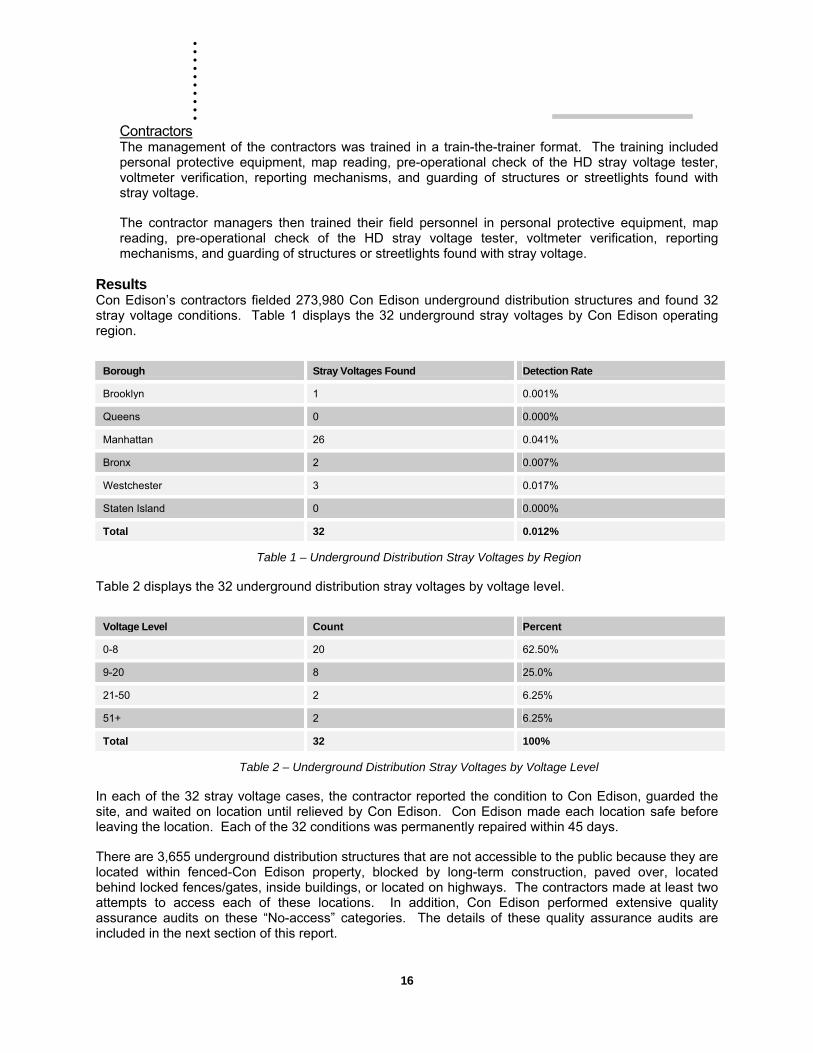
Results Con Edison’s contractors fielded 273,980 Con Edison underground distribution structures and found 32 stray voltage conditions. Table 1 displays the 32 underground stray voltages by Con Edison operating region.
Borough Stray Voltages Found Detection Rate
Brooklyn 1 0.001%
Queens 0 0.000%
Manhattan 26 0.041%
Bronx 2 0.007%
Westchester 3 0.017%
Staten Island 0 0.000%
Total 32 0.012%
Table 1 – Underground Distribution Stray Voltages by Region
Table 2 displays the 32 underground distribution stray voltages by voltage level.
Voltage Level Count Percent
0-8 20 62.50%
9-20 8 25.0%
21-50 2 6.25%
51+ 2 6.25%
Total 32 100%
Table 2 – Underground Distribution Stray Voltages by Voltage Level
In each of the 32 stray voltage cases, the contractor reported the condition to Con Edison, guarded the site, and waited on location until relieved by Con Edison. Con Edison made each location safe before leaving the location. Each of the 32 conditions was permanently repaired within 45 days.
There are 3,655 underground distribution structures that are not accessible to the public because they are located within fenced-Con Edison property, blocked by long-term construction, paved over, located behind locked fences/gates, inside buildings, or located on highways. The contractors made at least two attempts to access each of these locations. In addition, Con Edison performed extensive quality assurance audits on these “No-access” categories. The details of these quality assurance audits are included in the next section of this report.
17
Quality Assurance Measures Instituted There are 273,980 underground distribution structures within the Con Edison’s service territory. Con Edison developed a quality assurance plan to ensure that stray voltage testing was performed as specified. The reliability and error design parameters used were:
95% reliability within a ±10% relative precision level and satisfy established industry sample design criteria.
400 quality assurance audits are required to achieve a 95% confidence rate with a ±10% overall error that the stray voltage tests were conducted in accordance with Company specifications. In total, Con Edison performed 590 “Random Quality Assurance Audits” on the underground testing program, well above the 400 audits required for a 95% confidence rate.
Stray voltage was not found during any of these quality assurance audits.
These Random Quality Assurance Audits are divided into post work and work in progress audits.
UG Random Quality Assurance Audits Specification EO-10315 (Quality Assurance Of The Stray Voltage And Periodic Distribution Structure Safety Inspection Programs) calls for 400 quality assurance audits to be performed on the contractor stray voltage testing. The quality assurance audits are randomly selected from a database of all stray voltage tests. The audit consists of a field test for stray voltage. Con Edison performed 430 quality assurance audits. None of the quality assurance audits failed; no stray voltages were identified during the quality assurance process.
Work-in-Progress Audits Con Edison performed 160 work-in-progress audits to ensure the contractor was able read the Company’s Mains and Services (“M&S”) plates (on which the Company’s structures are identified and mapped), identify the underground structures in the field, and test the structure in accordance with EO-10129 (Operation of Low Voltage Detectors), including the pre-operational checks. These work-in-progress audits found no deficiencies.
Additional Quality Assurance Measures Instituted In addition to the Random Quality Assurance Audits, Con Edison also identified several areas for further investigation to ensure compliance with the Safety Standards. These are called “New Structures Mapped in 2005,” “New Structures Unmapped in 2005,” “No Access – Construction/Dumpster,” “No Access – Private Property (Locked Fence or Gate),” “No Access – Highway,” “No Access – Con Ed Property,” “No Access – Inside Building,” “No Access – Buried Box,” and “No Access – Paved Over.” The scope and results of each of these quality assurance audits are discussed below.
New Structures Mapped in 2005 The Access database was constructed from an extract of corporate mapping data in the beginning of 2005. In August, a second extract was run from corporate mapping. This second extract included only the structures that were added to the corporate mapping database in 2005. SSA compared the new structures against the Stray Voltage Log entries. If a structure did not have a testing entry for the current calendar year, it was issued to field personnel to be tested. There are 264 structures in this category.
New Structures Unmapped in 2005 To ensure all new structures were tested, all mapping departments reviewed their incoming work for any structures that had been added in the field, but have not been mapped on M&S plates as yet. SSA then compared these new structures against the Stray Voltage Log entries. If a structure did not have a testing entry for the current calendar year, it was issued to field personnel to be tested. There are 120 structures in this category.
. . . . . . .. . .
18
Structures With No Access Contractors make two attempts to locate and test all structures. The contractors categorize each of the “No Access” structures based on the field conditions such as long-term construction, dumpster on structure, behind a locked fence or gate, etc. If after two attempts, the structure is still “Not Found”, the contractors label the structure as “NF”. Con Edison personnel made a third and sometimes, fourth attempt to locate and test the structure. There are several types of “No Access” structures. Each condition and the quality assurance efforts involved are described below. There are a total of 3,655 structures in these categories.
No Access – Construction/Dumpster The contractors make two attempts to access and test all structures that are found not accessible. If a structure is inaccessible due to Construction Activity or Dumpster, then the name of construction Company, contact person, phone number and duration of construction activity or dumpster removal schedule (as denoted on the permit or posting) is required so as to facilitate a re-field of the structure. There is one structure in this category.
No Access – Private Property (Locked Fence or Gate) The contractors make two attempts to access and test all structures that are found not accessible due to the structure being on private property and behind a locked fence or gate. Con Edison personnel then examined Company records to verify that each structure is located on private property and is publicly inaccessible due to restricted access. Company forces fielded any structure that could not be verified via Company records and obtained the address and the name of the building owner for the Company’s records. There are 170 structures in this category. These structures will be removed from future stray voltage testing programs.
No Access – Highway The contractors make one attempt to access and test all structures that are found not accessible. The structure was not tested if the structure is located on a major city/state/national highway and requires a special permit for access. Contractors record these structures as a No Access due to NA-Highway, and record the name of the highway. Con Edison personnel verified against Company mapping records that the structures that are considered to be “Not Accessible to the Public”. There are 168 structures in this category.
No Access – Con Ed Property Contractors make one or two attempts to access and test all structures that are found not accessible due to being on Con Edison property. SSA and Regional Mapping then verified that each of the structures was behind a Company fence that access to the structure was limited to authorized personnel only. In each case, the name of the Company facility was recorded. There are 531 structures in this category. These structures will be removed from future stray voltage testing programs.
No Access – Inside Building Contractors make one attempt to access and test structures that are found not accessible due to their location inside a restricted area inside a building. Only transformer vaults should be inside a building – no manholes or service boxes. Company Energy Services personnel verified that the structure was within a building. In each case, the address and building owner was recorded. There are 280 structures in this category. These structures will be removed from future stray voltage testing programs.
No Access – Buried Box A buried box is a structure that is below grade and requires excavation to access the structure. These buried boxes are not publicly accessible and do not require a stray voltage test. Structures are identified on the corporate mapping system with a structure number prefix of BB (Buried Box) to indicate that the structure is buried. Many of the buried boxes

19
have a structure number with the BB appearing next to the structure number on the corporate map rather than as a prefix to the structure number. Contractors made two attempts to access and test these structures. Con Edison then verified approximately 20% of the structures that the contractors identified as buried boxes. Only two of these boxes were accessible to test. There are 1,616 structures in this category.
No Access – Paved Over If contractors, after two passes, and Company forces after another pass cannot find a structure, then the structure is sent to Regional Engineering for verification of existence and better location information. If Regional Mapping confirms that the structure does exist, Company and contractor crews then make a fourth attempt to locate and test the structure. After the four attempts, any structure not found is considered “paved over” and not accessible to the public. Company forces then conducted a 2% random sample on these paved-over structures to confirm that the structure was in fact paved over. There are 889 structures in this category.
Not Found – Verified Data Error If contractors, after two passes, and Company forces after another pass cannot find a structure, then the structure is sent to Regional Engineering for verification of existence and better location information. Regional Mapping researches each of the structures in question by reviewing Company records. If Regional Mapping confirms that the structure does not exist, then the structure is categorized as “Data Error.” There are 575 structures in this category.
. . . . . . .. . .
20
Stray Voltage Testing Of Overhead Distribution Structures
Scope The PSC’s Safety Standards require that electric utilities must test “all electric facilities that are capable of conducting electricity and are publicly accessible.” There are 278,612 wooden poles on Con Edison’s distribution system. Conductive metallic attachments seven feet or less above grade on wooden poles are considered publicly accessible except for poles that are:
1. On private property and behind a locked fence or gate,
2. On Con Edison property and behind a locked fence or gate, or
3. Inaccessible due to long-term construction.
Con Edison’s stray voltage testing procedures, EO-10358 and B-63, require stray voltage testing of all publicly accessible metallic attachments (≤7ft from grade) to a wood distribution pole with Con Edison facilities. A publicly accessible metallic attachment can belong to any party using the pole for attachments, such as, Con Edison, Verizon, fire departments, local departments of transportation, cable television companies, etc. These attachments include ground wires, riser pipes, anchor guys, pedestrian walk/don’t walk signals, fire call boxes, etc.
The overhead distribution structure stray voltage-testing program is managed in an Access database. The database was created from an extract of the wooden poles contained in the Company’s corporate mapping system. The database was given to a contractor to perform stray voltage testing. To ensure that all poles were included in the database, the contractor was instructed to follow a pole line even when the corporate map indicated that the line ended. The contractor utilized hand held computers to record the time and date and results of the stray voltage test. The data from the handheld was then uploaded to the database. Once uploaded, reports can be run, including:
1. Structures pending.
2. Structures complete.
3. Structures pass/fail.
Simultaneously with stray voltage testing, the contractors conducted an inventory and inspected the poles and attached equipment.
Overall Program The overhead distribution structure stray voltage testing/inspection/inventory program began in March of 2005 and was completed in October. Con Edison’s contractor visited every Con Edison-owned pole, every Verizon-owned pole with Con Edison attachments, and third-party-owned poles with Con Edison attachments. The contractor utilized handheld computers to record the stray voltage test result, inventory information, and GPS location of each pole. The contractor was directed to follow the pole line to the end, including secondary cables.
Stray Voltage Test Procedure Con Edison developed a variety of specifications and procedures for its stray voltage-testing program. Specifications EO-5100, EO-100175, and EO-10129 govern the manufacture, purchase and operation of low voltage detectors. Bulletin 63 contains the stray voltage testing procedure used by Con Edison personnel. EO-10358 addresses the annual stray voltage-testing program that is conducted by contractors. In addition, EO-10360 was developed to troubleshoot streetlights correctly. The procedures described below are included in the Appendix.
21
EO-5100 (Low Voltage Detectors - Stray Voltage) This specification details the requirements for the manufacture of low voltage detectors and associated test devices that are to be used for stray voltage testing, including materials, impact resistance, operating temperature range, voltage detection capabilities, and labeling.
EO-100175 (Purchase Recommendation - Low Voltage Detectors For Stray Voltage) This purchase recommendation covers low voltage detectors and test devices for stray voltage testing. The specification currently identifies only the HD-LV-S-5 as an approved detector for AC stray voltage detection by Con Edison personnel or contractors.
EO-10129 (Operation And Maintenance Of Low Voltage Detector For Stray Voltage) This specification describes the step-by-step operation of the HD-LV-S-5 stray voltage detector. The specification includes pre-operational checks and prohibits using rubber gloves during testing.
B-63 (Stray Voltage Testing Of Company Structures And Streetlights) This bulletin describes the equipment that must be tested in/on the overhead, underground, and URD systems, including testing of streetlights. The bulletin requires Con Edison personnel to test a structure and streetlight before working in/on the structure and again when work is completed for the day. The bulletin addresses direct current testing for structures that have both alternating current and direct current facilities. The bulletin addresses voltmeter verification of a stray voltage indication from the HD device, stray voltage reporting, and guarding of any facility or streetlight found with stray voltage.
EO-10358 (Annual Contractor Stray Voltage Inspection Procedure) This specification describes the annual stray voltage testing that is performed by contractors. It describes how to test a Con Edison structure or streetlight, when to test a streetlight, what pole attachments need to be tested, data transfer requirements, and notification procedures in case a stray voltage is identified, and guarding of any facility or streetlight found with stray voltage.
EO-10360 (Troubleshooting of Streetlights) This step-by-step procedure governs troubleshooting of underground streetlight services. The specification also requires load testing of the Con Edison supply cables of all streetlights worked on by Con Edison. The load test is necessary to determine if the Con Edison neutral cable is defective.
Shunt Resistor Overhead lines are not shielded and can induce voltages on metallic surfaces. These voltages are normally not harmful, and they do not involve a failed component of the distribution system.
The HD stray voltage indicator and a digital voltmeter can falsely indicate a potentially harmful stray voltage condition in the presence of induced voltage.
A digital voltmeter’s very high input impedance is designed not to affect the circuit being tested. The design has the disadvantage of being unable to distinguish a stray voltage capable of delivering a harmful electric shock from an induced voltage with no current carrying capacity. A shunt resister can be used in conjunction with the voltmeter to determine whether the voltage is produced by current (presenting the possibility for harm) or is induced (harmless).
We have developed a shunt resistor to be used in combination with the Fluke voltmeter when a potential stray voltage has been identified on the overhead system. The step-by-step procedure is described in the Appendix.
. . . . . . .. . .
22
Training Con Edison developed training for both Company employees and contractors on how to conduct stray voltage testing. All contractors and employees were trained on map reading, conducting stray voltage tests, reporting of stray voltages, and guarding structures found with stray voltage.
Company Employees Company employees received on-the-job training (OJT) course number ELE0004 covering map reading, the pre-operational check of the HD stray voltage tester, voltmeter verification, reporting mechanisms, and guarding of structures or streetlights found with stray voltage. These employees conducted post-work and work-in-progress quality assurance audits of the contractors performing the stray voltage testing.
Contractors The management of the contractors was trained in a train-the-trainer format. The training included personal protective equipment, map reading, pre-operational check of the HD stray voltage tester, voltmeter verification, reporting mechanisms, and guarding of structures or streetlights found with stray voltage. In the case of the overhead stray voltage testing, the training also included identification of metallic pole attachments such as guy wires, riser pipes, ground rods, traffic signal equipment, etc.
The contractor managers then trained their field personnel in personal protective equipment, map reading, pre-operational check of the HD stray voltage tester, voltmeter verification, reporting mechanisms, and guarding of structures or streetlights found with stray voltage. In the case of the overhead stray voltage testing, the training also included identification of metallic pole attachments such as guy wires, riser pipes, ground rods, traffic signal equipment, etc.
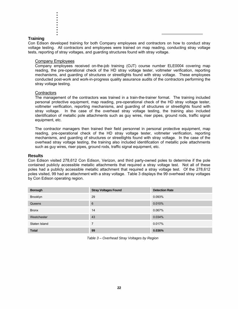
Results Con Edison visited 278,612 Con Edison, Verizon, and third party-owned poles to determine if the pole contained publicly accessible metallic attachments that required a stray voltage test. Not all of these poles had a publicly accessible metallic attachment that required a stray voltage test. Of the 278,612 poles visited, 99 had an attachment with a stray voltage. Table 3 displays the 99 overhead stray voltages by Con Edison operating region.
Borough Stray Voltages Found Detection Rate
Brooklyn 29 0.093%
Queens 6 0.010%
Bronx 14 0.067%
Westchester 43 0.034%
Staten Island 7 0.017%
Total 99 0.036%
Table 3 – Overhead Stray Voltages by Region
23
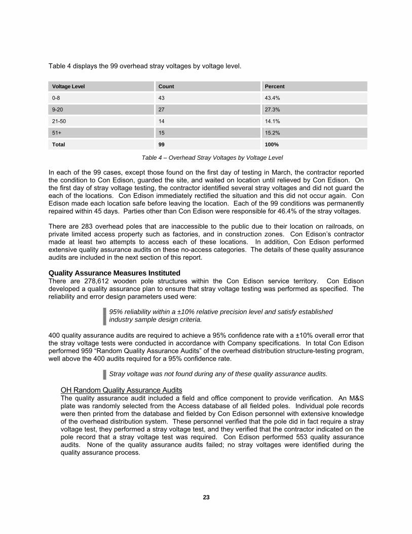
Table 4 displays the 99 overhead stray voltages by voltage level.
Voltage Level Count Percent
0-8 43 43.4%
9-20 27 27.3%
21-50 14 14.1%
51+ 15 15.2%
Total 99 100%
Table 4 – Overhead Stray Voltages by Voltage Level
In each of the 99 cases, except those found on the first day of testing in March, the contractor reported the condition to Con Edison, guarded the site, and waited on location until relieved by Con Edison. On the first day of stray voltage testing, the contractor identified several stray voltages and did not guard the each of the locations. Con Edison immediately rectified the situation and this did not occur again. Con Edison made each location safe before leaving the location. Each of the 99 conditions was permanently repaired within 45 days. Parties other than Con Edison were responsible for 46.4% of the stray voltages.
There are 283 overhead poles that are inaccessible to the public due to their location on railroads, on private limited access property such as factories, and in construction zones. Con Edison’s contractor made at least two attempts to access each of these locations. In addition, Con Edison performed extensive quality assurance audits on these no-access categories. The details of these quality assurance audits are included in the next section of this report.
Quality Assurance Measures Instituted There are 278,612 wooden pole structures within the Con Edison service territory. Con Edison developed a quality assurance plan to ensure that stray voltage testing was performed as specified. The reliability and error design parameters used were:
95% reliability within a ±10% relative precision level and satisfy established industry sample design criteria.
400 quality assurance audits are required to achieve a 95% confidence rate with a ±10% overall error that the stray voltage tests were conducted in accordance with Company specifications. In total Con Edison performed 959 “Random Quality Assurance Audits” of the overhead distribution structure-testing program, well above the 400 audits required for a 95% confidence rate.
Stray voltage was not found during any of these quality assurance audits.
OH Random Quality Assurance Audits The quality assurance audit included a field and office component to provide verification. An M&S plate was randomly selected from the Access database of all fielded poles. Individual pole records were then printed from the database and fielded by Con Edison personnel with extensive knowledge of the overhead distribution system. These personnel verified that the pole did in fact require a stray voltage test, they performed a stray voltage test, and they verified that the contractor indicated on the pole record that a stray voltage test was required. Con Edison performed 553 quality assurance audits. None of the quality assurance audits failed; no stray voltages were identified during the quality assurance process.
. . . . . . .. . .
24
Work-in-Progress Audits Con Edison personnel performed 406 work-in-progress audits to ensure the contractor was able read the M&S plate and identify the poles with Con Edison attachments. The contractor was required to identify the pole attachments and state which attachments required testing. The contractor then tested the attachments with the approved device and in accordance with EO-10129 (Operation of Low Voltage Detectors), including the pre-operational checks.
Additional Quality Assurance Measures Instituted In addition, Con Edison also identified several areas in which there was potential for an overhead structure to be missed during the annual stray voltage-testing program. These are called “Fringe Plates,” “No Access Poles,” “Not Found Poles,” and “Zero Poles Plates.” The scope and results of each of these quality audits are discussed below.
Fringe Plates A fringe plate is an M&S plate covering a border of one of Con Edison’s six geographic regions. The border could abut another utility’s service territory or a body of water or could be the border between regions. These border areas may have very few poles that possibly could be missed by the Company forces responsible for mapping or by the contractor conducting the stray voltage testing. There are approximately 1500 fringe plates on the Con Ed system.
Con Edison performed a quality assurance audit of 2% of the 1500 M&S plates selected on a random basis – approximately 30 plates. The scope of work included field inspecting the entire plate and marking on the plate (with a highlighter) all the wood poles found in the field. Quality assurance personnel then compared the marked up plate to the data submittal by the contractor to ensure all poles were tested.
No Access Poles Poles that are in the database, field, and/or on the secondary map, but cannot be accessed to perform a stray voltage test are considered not to be accessible to the public. The Company requires the contractor to make two attempts to test the poles. Con Edison quality assurance personnel then verified all of the No Access conditions. There are several types of “No Access” structures. Each condition and the quality assurance efforts involved are described below. There are a total of 283 publicly inaccessible poles in these categories.
No Access – Residential (Rear Yard) The contractors make two attempts to access and test all poles that are found not accessible. If a structure is inaccessible due to a locked gate or the customer refuses access, the name of customer and address is obtained so as to facilitate a re-field of the structure. Company forces then attempt to access the structure by displaying their Company identification. If Company forces are unsuccessful, Energy Services coordinates an appointment to test the structure. There is one pole remaining in this category. Con Edison is attempting to schedule an appointment with the customer, but has been unsuccessful so far.
No Access – Commercial (Behind Locked Gate) The contractors make two attempts to access and test all poles that are found not accessible. If a structure located on commercial property and is inaccessible due to a locked gate, the name of customer and address is required so as to facilitate a re-field of the structure. Company forces then attempt to access the structure by displaying their Company identification. There are 46 poles that remain inaccessible in this category.
No Access – Con Edison Property Contractors make two attempts to access and test all poles that are found not accessible to the public because they are located on Con Edison’s property. SSA and Regional Mapping verified that each of the poles was behind a Company fence that limited access to the

25
structure to authorized personnel only. In each case, the name of the Company facility was recorded. There are 17 poles in this category.
No Access – Railroad The contractors make two attempts to access and test all poles that are found not accessible. A number of poles were found to be inaccessible due to location on railroad property. SSA performed a quality assurance audit on 23 three of these poles reviewing Company records and conducting field visits. A total of 206 poles are inaccessible due to location on railroad property.
No Access – Construction The contractors make two attempts to access and test all poles that are found not accessible. If a pole is inaccessible due to construction, the name of construction Company, customer and address is obtained so as to facilitate a re-field of the structure. Company forces then attempted to access the pole by displaying their Company identification. There are 13 poles in this category.
Not Found Poles Poles that are in the database and/or on the corporate map, but cannot be located in the field require two attempts by the contractor. Company forces then conducted a quality assurance audit of 2% of these poles selected on a random basis. Any pole not found after two contractor passes and the random quality assurance audits are deemed to be data errors. Con Edison performed 120 quality assurance audits and found 7 poles.
Zero Pole Plates Based on secondary mapping data, there are approximately 3000 M&S plates that do not have poles (This does not include M&S plates for Manhattan which has no poles). Quality Assurance sampled 2% of these plates – approximately 60 – to determine if there were any poles with Con Edison facilities that have not been mapped. The scope of work included driving the entire area encompassed by the plate to verify that the M&S plate has no publicly accessible wood poles with Con Edison attachments. Con Edison performed 62 quality assurance audits and found one M&S plate, previously identified as a zero pole plate, to have poles.
. . . . . . .. . .
26
Stray Voltage Testing Of Municipality Owned Streetlights
Scope The Safety Standards require that electric utilities test all publicly accessible metallic pole streetlights and traffic signals (“streetlights”). Con Edison does not own or maintain the streetlights in its service territory (New York City and the County of Westchester). Metal pole streetlights are considered publicly accessible as long as the pole is located on a public thoroughfare (roadway) and is not:
1. On private property,
2. On a highway,
3. On a pier,
4. Inside a park,
5. On Con Ed property, or
6. Inaccessible due to long term construction
Con Edison’s stray voltage testing procedures, EO-10358 and B-63, require stray voltage testing of all publicly accessible metal pole streetlights. The scope of work did not require stray voltage testing of streetlights located on highways, piers, on private property such as parking lots, or inside parks. Metal poles located on the perimeter of the park adjacent to a roadway were tested. The stray voltage testing on all streetlights was performed at night.
The streetlight stray voltage-testing program data is maintained in an Access database. Con Edison maps only the streetlights that are directly fed by Con Edison structures. In many cases, however, the NYCDOT and the Westchester municipalities supply multiple streetlights or traffic signals from a common Con Edison service point. Approximately 30% of all publicly accessible streetlights that require stray voltage testing are not on Con Edison maps.
Con Edison instituted a system wide inventory of all publicly accessible streetlights in combination with a stray voltage-testing program. The inventory included capturing the Global Positioning System (GPS) coordinates and installing a barcode tag on each of the publicly accessible streetlights. Since approximately 30% of the streetlights are not on Con Edison maps, the scope of work included visiting every street in the Company’s service territory to test, record GPS coordinates, and install a barcode on each streetlight. The system wide inventory created in 2005 will facilitate testing and data reconciliation in future testing programs.
Overall Program The 2005 streetlight stray voltage-testing program began in May and was completed in October. Con Edison hired contractors to test all streetlights for stray voltage and perform a physical inventory of all publicly accessible streetlights. All data was captured using handheld computers and uploaded to a Con Edison server into a database built for the streetlight testing and inventory programs.
Test Procedure Con Edison developed a variety of specifications and procedures for its stray voltage-testing program. Specifications EO-5100, EO-100175, and EO-10129 govern the manufacture, purchase and operation of low voltage detectors. Bulletin 63 contains the stray voltage testing procedure used by Con Edison personnel. EO-10358 addresses the annual stray voltage-testing program that is conducted by contractors. In addition, EO-10360 was developed to troubleshoot streetlights correctly. The procedures described below are included in the Appendix.
27
EO-5100 (Low Voltage Detectors - Stray Voltage) This specification details the requirements for the manufacture of low voltage detectors and associated test devices that are to be used for stray voltage testing, including materials, impact resistance, operating temperature range, voltage detection capabilities, and labeling.
EO-100175 (Purchase Recommendation - Low Voltage Detectors For Stray Voltage) This purchase recommendation covers low voltage detectors and test devices for stray voltage testing. The specification currently identifies only the HD-LV-S-5 as an approved detector for AC stray voltage detection by Con Edison personnel or contractors.
EO-10129 (Operation And Maintenance Of Low Voltage Detector For Stray Voltage) This specification describes the step-by-step operation of the HD-LV-S-5 stray voltage detector. The specification includes pre-operational checks and prohibits using rubber gloves during testing.
B-63 (Stray Voltage Testing Of Company Structures And Streetlights) This bulletin describes the equipment that must be tested in on the overhead, underground, and URD systems, including testing of streetlights. The bulletin requires Con Edison personnel to test a structure and streetlight before working in/on the structure and again when work is completed for the day. The bulletin addresses direct current testing for structures that have both alternating current and direct current facilities. The bulletin addresses voltmeter verification of a stray voltage indication from the HD device, stray voltage reporting, and guarding of any facility or streetlight found with stray voltage.
EO-10358 (Annual Contractor Stray Voltage Inspection Procedure) This specification describes the annual stray voltage testing that is performed by contractors. It describes how to test a Con Edison structure or streetlight, when to test a streetlight, what pole attachments need to be tested, data transfer requirements, and notification procedures in case a stray voltage is identified, and guarding of any facility or streetlight found with stray voltage.
EO-10360 (Troubleshooting of Streetlights) This step-by-step procedure governs troubleshooting of underground streetlight services. The specification requires load testing of the Con Edison supply cables of all streetlights worked on by Con Edison. The load test is necessary to determine if the Con Edison neutral cable is defective.
Training Con Edison developed training for both Company employees and contractors on how to conduct stray voltage testing. Company employees were trained on map reading, conducting stray voltage tests, reporting of stray voltages, and guarding structures found with stray voltage. These employees conducted post-work and work-in-progress quality assurance audits of the contractors performing streetlight stray voltage testing.
The management of the contractors was trained in a train-the-trainer format. The training included personal protective equipment, map reading, pre-operational check of the HD stray voltage tester, voltmeter verification, reporting mechanisms, and guarding of structures or streetlights found with stray voltages.
The contractor managers then trained their field personnel in personal protective equipment, map reading, pre-operational check of the HD stray voltage tester, voltmeter verification, reporting mechanisms, and guarding of structures or streetlights found with stray voltage.

. . . . . . .. . .
28
Results Con Edison visited 172,977 NYC-DOT and local municipally owned streetlights to perform a stray voltage test. Of the 172,977 poles tested, 1083 were found with a stray voltage.
Total 1083 0.63%
Table 5 displays the 1083 streetlights with stray voltage by Con Edison operating region.
Borough Stray Voltages Found Detection Rate
Brooklyn 79 0.15%
Queens 404 0.81%
Manhattan 9 0.03%
Bronx 283 1.33%
Westchester 17 0.12%
Staten Island 291 3.83%
Total 1083 0.63%
Table 5 – Streetlight Stray Voltages by Region
Table 6 displays the 1083 streetlights with stray voltage by level voltage.
Voltage Level Count Percent
0-8 452 42%
9-20 435 40%
21-50 141 13%
51+ 55 5%
Total 1083 100%
Table 6 – Streetlight Stray Voltages by Voltage Level
In each of the 1083 cases of streetlight stray voltage, the contractor reported the condition to Con Edison, guarded the site, and waited on location until relieved by Con Edison. Con Edison made each location safe before leaving the location. All but four of the 1083 stray voltages were permanently repaired within 45 days. Repairs of the other four were made within 53 to 61 days. The repair of these four streetlights was delayed because the stray voltage responsibility was not initially determined. Parties other than Con Edison were responsible for 52.0% of the stray voltages.
There are 276 streetlights that are inaccessible to the public due to location in long-term construction zones or restricted access security zones such as around Wall Street. Con Edison made at least two attempts to access each of these locations. In addition, Con Edison performed extensive quality assurance audits on No-access categories. The details of these quality assurance audits are included in the next section of this report.
Quality Assurance Measures Instituted There are approximately 173,000 publicly accessible streetlights within Con Edison’s service territory. Con Edison developed a quality assurance plan to ensure the stray voltage testing was performed as specified. The reliability and error design parameters used were:

29
95% reliability within a ±10% relative precision level and satisfy established industry sample design criteria.
400 quality assurance audits are required to achieve a 95% confidence rate with a ±10% overall error that the stray voltage tests were conducted in accordance with Company specifications. The streetlight quality assurance plan consists of quality assurance audits by Con Edison and contractor workforces. In total, Con Edison performed 980 “Random Quality Assurance Audits” and “Work-in-Progress Audits” of the streetlight-testing program, well above the 400 audits required for a 95% confidence rate.
Stray voltage was not found during any of these quality assurance audits.
The quality assurance audits are comprised of two groups “Work-in-Progress” and “Post Work.”
Random Quality Assurance Audits Con Edison personnel performed 838 randomly selected post work audits to verify that the contractor visited the streetlight to perform a stray voltage test. Con Edison personnel observed if the contractor applied a barcode and a paint dot to the streetlight. Con Edison personnel also performed a stray voltage test. All 838 quality assurance audits passed the quality assurance audit.
Work-in-Progress Streetlights must be tested at night when the entire streetlight circuit is energized. Nighttime testing exposes neutral problems on the utility side of the streetlight circuit that would not be apparent during daytime testing when the circuit is not on. Con Edison conducted 142 work in progress audits to ensure the stray voltage contractor was testing the streetlights at night and in accordance with the testing specifications. In all cases, the contractor was found to be using the appropriate test device and testing after dark. One contractor, although was found to be testing at night with the appropriate equipment, was nonetheless discharged from the testing program based on poor record keeping of its stray voltage testing and incorrect barcode installation.
Additional Quality Assurance Measures Instituted In addition, Con Edison identified several areas in which there was potential for a streetlight to be missed during the annual stray voltage-testing program. These are called “No Access Streetlights”, “Plates with Mapped Streetlights” and “Plates without Mapped Streetlights.” The scope and results of each of these quality audits will be discussed below.
No Access Streetlights Most streetlights can be accessed for stray voltage testing. The testing contractors identified 276 streetlights where they did not have access to test the structure due to construction or restricted access. These streetlights are also considered inaccessible to the public. Con Edison performed a quality assurance audit on 2% of these no access streetlights.
No Access - Construction The contractors made two attempts to access and test all streetlights that were found not accessible. SSA performed a quality assurance audit on 2% of these no access streetlights to verify the streetlights were inaccessible due to construction. There are 71 streetlights in this category.
No Access – Restricted Access The contractors made two attempts to access and test all streetlights that are found not accessible. If a streetlight is inaccessible due to restricted access, such as security zones placed around Wall Street, SSA performed a quality assurance audit on 2% of these streetlights to ensure the streetlight were inaccessible due to restricted access zones. There are 205 streetlights in this category.
. . . . . . .. . .
30
Verification of Streetlight Plates Tested The stray voltage-testing contractor is required to test the streetlights on every street in Con Edison’s service territory. Con Edison does not map approximately 30% of the streetlights because Con Edison does not directly supply the streetlights. Therefore, the quality assurance audits are divided into two components – plates with mapped streetlights and plates without.
Plates with Mapped Streetlights There 7,016 M&S plates with mapped streetlights. Con Edison performed a randomly selected quality assurance audit of 2% of these plates – 142 plates – to ensure that all publicly accessible streetlights have been tested. The scope of audit included field inspecting the streets on each plate to ensure that a barcode badge has been installed on all streetlights and marking (with a highlighter) all the metal poles with badges on the plate.
Plates without Mapped Streetlights There 6,808 M&S plates without mapped streetlights. Con Edison performed a randomly selected quality assurance audit on 2% of these plates – 135 plates – to verify there are no publicly accessible streetlights in the mapped area. The scope of the audit included driving through all the streets on each plate to verify that the M&S plate has no publicly accessible metal poles on roadways.
Verification of DOT Repairs Con Edison’s procedure requires Con Edison employees to troubleshoot streetlights found with stray voltage to determine if the responsibility for repairs belongs to Con Edison or with the NYCDOT/Westchester local municipality. When Con Edison has determined that the problem requires DOT response, the DOT is notified via email, and Con Edison marks the light with three bands of black tape. The tape bands signify to the DOT that this is a stray voltage light and care should be exercised during troubleshooting.
Con Edison contractors install a barcode identification badge only after testing a streetlight and finding no stray voltage. For streetlights with stray voltage detected on the first pass the contractors were required to return after a minimum of 72 hours to test the light again before installing the badge. Of the total 1083 streetlights found with stray voltage, 563 were determined to require repairs by the streetlight owner.
Stray Voltage Repairs In each of the 1083 cases of streetlight stray voltage, the contractor reported the condition to Con Edison, guarded the site, and waited on location until relieved by Con Edison. Con Edison made each location safe before leaving the location. All but 4 of the 1083 stray voltages were permanently repaired within 45 days. Repairs of the other 4 were made within 53 to 61 days. The repair of these four streetlights was delayed because the stray voltage responsibility was not initially determined.

31
Stray Voltage Testing Of Overhead Transmission Facilities
Scope The vast majority of overhead transmission structures are lattice steel structures or steel poles located on right-of-way (ROW) that is either owned by Con Edison or on easements granted to Con Edison. Initial stray voltage testing was performed on 1192 steel structures and 24 wood poles and associated guy wires using voltmeters in accordance with Con Edison specification CE-ES-1043. Con Edison personnel conducted this stray voltage testing at each tower in conjunction with the periodic ground patrol of the overhead transmission system. Testing did not indicate the presence of stray voltage at any location.
Overall Program Initial stray voltage testing began on 3/11/05 and was completed on 5/27/05. Follow up testing using a shunt resistor, which is described below, continued through November. Trained Con Edison Transmission Line Maintenance (TLM) personnel tested all towers for stray voltage. The stray voltage tests were documented in a database that recorded the structure number, date tested, employee name/number, and the test result.
Test Procedure Con Edison developed a stray voltage testing procedure CE-ES-1043 (Procedure to Measure Stray Voltage of Overhead Transmission Structures)(see Appendix) to address stray voltage testing of overhead transmission facilities. This specification stipulates that all transmission towers, any guy wires connected to transmission towers or poles, and fences that enclose any tower or pole shall be tested for stray voltage every year. In addition, Company personnel will conduct stray voltage testing on transmission structures that are actively worked on each day. Each stray voltage test shall be recorded on the daily work record (Daily Crew Activity Report). This data will be transferred to an electronic database. Voltmeters are used for all stray voltage testing.
Shunt Resistor Overhead lines are not shielded and can induce voltages on metallic surfaces. These voltages are normally not harmful, and they do not involve a failed component of the distribution system.
The HD stray voltage indicator and a digital voltmeter can falsely indicate a potentially harmful stray voltage condition in the presence of induced voltage.
A digital voltmeter’s very high input impedance is designed not to affect the circuit being tested. The design has the disadvantage of being unable to distinguish a stray voltage capable of delivering a harmful electric shock from an induced voltage with no current carrying capacity. A shunt resister can be used in conjunction with the voltmeter to determine whether the voltage is produced by current (presenting the possibility for harm) or is induced (harmless).
We have developed a shunt resistor to be used in combination with the Fluke voltmeter when a potential stray voltage has been identified on the overhead system. The step-by-step procedure is described in the Appendix.
Training Company employees assigned to the Transmission Line Maintenance Section of the Transmission Operations Department perform the testing of overhead transmission structures. These employees have significant knowledge of the overhead transmission system and normally work on the transmission right-of-way (ROW), performing inspections and maintenance work. They are also experienced in the use of voltmeters, which were used to perform stray voltage testing on the ROW. They received on-the-job training for stray voltage testing via course number ELE0004. They also reviewed OP-420-3, Con Edison’s Overhead Transmission Line Ground Patrol Standard.
. . . . . . .. . .
32
Results Initial testing was performed on 1192 steel structures and 24 wood poles and associated guy wires using voltmeters in accordance with Con Edison specification CE-ES-1043. There were 248 steel structures, 8 wood poles, and 5 guy wires where initial measurements yielded greater than 1 volt. These locations were subsequently re-tested using a shunt resistor. When the shunt resistor was used only five steel towers had readings greater than 1 volt. Measurements ranged between 1.04 volts and 1.70 volts. Inspection of these locations did not reveal any improper conditions that could contribute to stray voltage; therefore no corrective action was required. The presence of voltage readings in the ranges referenced is considered to be induction consistent with the normal operation of the overhead system.
Quality Assurance Measures Instituted In accordance with CE-ES-1043, a planner in TLM, who has knowledge and expertise in overhead transmission, but who did not perform or directly supervise the stray voltage testing, conducted fifty QA inspections at locations on various transmission lines.
Stray voltage was not found during any of these quality assurance audits.
The QA checks performed confirmed the accuracy of the results from the stray voltage-testing program.
33
Stray Voltage Testing Of Underground Transmission Facilities
Scope There are 1737 underground transmission facilities throughout Con Edison’s territory. Qualified contractors performed the stray voltage testing on publicly accessible transmission manhole covers in the five boroughs of New York City and Westchester. Publicly inaccessible structures, defined as being behind a locked gate/fence or inside a substation, were not tested for stray voltage.
Overall Program The underground transmission stray voltage testing began in June of 2005 and was completed in October of 2005. Qualified contractors performed the stray voltage testing. The contractors were provided with a list of all underground transmission structures. The list was generated by extracting data from Transmission Operations’ work management system (MAXIMO). The contractor fielded the structure location, tested the location for stray voltage, and documented the results of the test on the list for submission to Con Edison.
Test Procedure Con Edison developed three specifications that govern the manufacture, purchase and operation of low voltage detectors – EO-5100, EO-100175, and EO-10129. Bulletin 63 was developed to address the stray voltage testing procedure by Con Edison personnel. EO-10358 covers the annual stray voltage-testing program that is conducted by contractors. The procedures described below are included in the Appendix.
EO-5100 (Low Voltage Detectors - Stray Voltage) This specification details the requirements for the manufacture of low voltage detectors and associated test devices that are to be used for stray voltage testing, such as materials, impact resistance, operating temperature range, voltage detection capabilities, and labeling.
EO-100175 (Purchase Recommendation - Low Voltage Detectors For Stray Voltage) This purchase recommendation covers low voltage detectors and test devices for stray voltage testing. The specification approves only the HD-LV-S-5 as the approved detector for AC stray voltage detection by Con Edison personnel or contractors.
EO-10129 (Operation And Maintenance Of Low Voltage Detector For Stray Voltage) This specification describes the step-by-step operation of the HD-LV-S-5 stray voltage detector. The specification includes pre-operational checks and not using rubber gloves during testing.
B-63 (Stray Voltage Testing Of Company Structures And Streetlights) This bulletin describes the equipment that must be tested in on the overhead, underground, and URD systems. The specification also includes testing of streetlights. The bulletin requires Con Edison personnel to test a structure and streetlight before working in/on the structure and again when work is complete. The bulletin addresses direct current testing for structures that have both alternating current and direct current facilities. The bulletin addresses voltmeter verification of a stray voltage indication from the HD device, stray voltage reporting, and guarding of any facility or streetlight found with stray voltage.
EO-10358 (Annual Contractor Stray Voltage Inspection Procedure) This specification describes the annual stray voltage testing that is performed by contractors. It describes how to test a Con Edison structure or streetlight, when to test a streetlight, what pole attachments need to be tested, data transfer requirements, and notification procedures in case a stray voltage is identified, and guarding of any facility or streetlight found with stray voltage.
. . . . . . .. . .
34
Training Con Edison developed training for both Company employees and contractors on how to conduct stray voltage testing. Training topics included map reading, conducting stray voltage tests, reporting of stray voltages, and guarding stray voltages.
Company Employees Company employees received on the job training (OJT) developed by Transmission Operations. They received training in the pre-operational check of the HD stray voltage tester, voltmeter verification, reporting mechanisms, and guarding of structures found with stray voltages.
Contractors The management of the contractors were trained in a train-the-trainer format by SSA and the EH&S section of Construction Management. The training included personal protective equipment, map reading, pre-operational check of the HD stray voltage tester, voltmeter verification, reporting mechanisms, and guarding of structures or streetlights found with stray voltages. The contractor managers then trained their field personnel in personal protective equipment, map reading, pre-operational check of the HD stray voltage tester, voltmeter verification, reporting mechanisms, and guarding of structures or streetlights found with stray voltages.
Results There are 1737 underground transmission facilities throughout the Con Edison territory. The manhole covers of 1358 transmission structures that are accessible to public in the five boroughs of New York City and Westchester were tested for stray voltages. The test results did not indicate any presence of stray voltage. The remaining 379 structures were inaccessible to the public, as they are located either behind a locked gate/fence or inside of a substation thus stray voltage tests were not performed on this group.
Quality Assurance Measures Con Edison performed several types of quality assurance audits on the underground transmission stray voltage-testing program. Contractors performed the stray voltage testing of underground transmission facilities. These contractors, who also performed testing on underground distribution structures, were subject to field audits by Underground Transmission personnel to ensure the contractor was able read the Company’s maps (on which the Company’s structures are identified), identify the underground structures in the field, and test the structure in accordance with EO-10129 (Operation of Low Voltage Detectors), including the pre-operational checks. These work-in-progress audits found no deficiencies.
Underground Transmission personnel also performed checks at 35 locations following stray voltage testing. The QA checks performed confirmed the accuracy of the results from the stray voltage-testing program.
Stray voltage was not found during any of these quality assurance audits.
In addition to these quality assurance initiatives, Con Edison identified several areas in which there was a need for further investigation to ensure compliance with the Safety Standards. These are called “New Structures Unmapped in 2005,” “No Access – Private Property (Locked Fence or Gate),” and “No Access – Con Ed Property.” The scope and results of each of these quality audits are discussed below.
New Structures Unmapped in 2005 To ensure all new structures were tested, Transmission Operations reviewed recently installed facilities to ensure they were included in the testing. As a result of this review, 18 structures were added to the listing and subsequently tested in 2005.
Structures With No Access Contractors make two attempts to locate and test all structures. The contractors categorize each of the “No Access” structures based on the field conditions such as long term construction, dumpster on
35
structure, behind a locked fence or gate, etc. If after two attempts, the structure is still “Not Found”, the contractors label the structure as “NF”. Con Edison personnel then make a third and sometimes, fourth attempt to locate and test the structure. There are several types of “No Access” structures. Each condition and the quality assurance efforts involved are described below. There are a total of 379 structures in these categories.
No Access – Private Property (Locked Fence or Gate) The contractors make two attempts to access and test all structures that are found not accessible due to the structure being on private property and behind a locked fence or gate. Con Edison personnel then verified all of these locations against Company records, and fielded any structure that could not be verified. Two underground transmission structures were identified as being “No Access – Private Property (Locked Fence or Gate). These structures are considered inaccessible to the public.
No Access – Con Ed Property Contractors make one attempt to access and test all structures that are found not accessible due to being on Con Ed property. Transmission Operations personnel then verified that each of the structures was behind a Company fence (typically a substation fence) that limited access to the structure to authorized personnel only. In each case the name of the Company facility was recorded. There are 377 structures in this category. These structures are considered inaccessible to the public.
. . . . . . .. . .
36
Stray Voltage Testing Of Substation Facilities
Scope The PSC’s Safety Standards require that electric utilities test “all electric facilities that are capable of conducting electricity and are publicly accessible.” The PSC’s “Order Issuing Safety Standards,” issued January 5, 2005, requires that substation fences be tested for stray voltage. There are 92 substations on 61 separate sites that that require perimeter stray voltage testing. Three other substations are located within larger Con Edison properties, and the exterior fences of those substations are not publicly accessible. All 61 of these sites were tested for stray voltage. This section describes the stray voltage testing, quality assurance, and training for transmission and substation facilities.
Overall Program Perimeter fencing including other electrical conductive materials accessible to the public, of sixty-one (61) substation sites in the five boroughs of New York City and Westchester were tested for stray voltages during the months of July through September 2005. Qualified substation mechanics and supervisors performed the stray voltage testing. All stray voltage tests were recorded in MAXIMO, the work management system that is used by Substation Operations to track tests, inspections and required repairs. Table 7 shows the count of substation and PURS facility sites by region. Some sites contain more than one substation.
Brooklyn Queens Manhattan Bronx Westchester Staten Island Total
9 5 20 4 17 6 61
Table 7 – Substations Count by Region
Test Procedure Substations Operations Procedure 0800-0038/00 (Substations Stray Voltage Testing And Station Inspection) requires testing for electric potential (voltage testing) on steel, aluminum or other electrical conducting materials on substation perimeters where such materials are accessible to the general public. These materials include but are not limited to fences, doors, roll-up gates, metallic delivery boxes, dielectric fluid delivery ports, and Siamese connections that may become energized as a result of stray voltage.
Stray voltage testing is performed on perimeter fencing and other electrical conductive materials of substations where such materials are accessible to the general public. The surface of electrical conductive materials on all station perimeters will be tested annually using an approved tester (i.e., glow, no glow). The direct contact low voltage tester (LV-S-5) detects voltages above 5 volts (indicated by a glow of the device). If the device glows, a fluke meter will be used to obtain a numerical reading. If there is any voltage reading (above 0 volts), then the location shall be guarded until the voltage is eliminated (temporary grounding may be used). Permanent repairs will be made within 45 days. All fence lines, entrance doors, transformer vault enclosures and any metal exterior trimmings, which have the potential to conduct electricity and are accessible to the public, must be tested once during each 12-month period ending November 30. Qualified Con Edison personnel performed all stray voltage testing.
Con Edison developed three specifications that govern the manufacture, purchase and operation of low voltage detectors – EO-5100, EO-100175, and EO-10129. Bulletin 63 was developed to address the stray voltage testing procedure by Con Edison personnel. The procedures described below are included in the Appendix.
EO-5100 (Low Voltage Detectors - Stray Voltage) This specification details the requirements for the manufacture of low voltage detectors and associated test devices that are to be used for stray voltage testing, such as materials, impact resistance, operating temperature range, voltage detection capabilities, and labeling.

37
EO-100175 (Purchase Recommendation - Low Voltage Detectors For Stray Voltage) This purchase recommendation covers low voltage detectors and test devices for stray voltage testing. The specification approves only the HD-LV-S-5 as the approved detector for AC stray voltage detection by Con Edison personnel or contractors.
EO-10129 (Operation And Maintenance Of Low Voltage Detector For Stray Voltage) This specification describes the step-by-step operation of the HD-LV-S-5 stray voltage detector. The specification includes pre-operational checks and not using rubber gloves during testing.
Training Employee’s are trained and demonstrate the ability to perform Stray Voltage Testing following Company specifications and safety procedures through training module CSG0020 (Stray Voltage Training & Testing SSO). The training includes the reasons for stray voltage tests, PSC Case 04-M-0159 information, safety concerns and conditions, personnel protective equipment, stray voltage testing, and program administration.
Results The perimeter at two of the 61 sites measured voltages less than one volt, and the remaining sites did not indicate any presence of stray voltage. The two sites with a measurable voltage, but less than one volt, were inspected for any deficiencies, and none were observed. The voltage is naturally occurring.
Quality Assurance Measures Substations Operations MAXIMO group performed quality assurance audits for the substation stray voltage-testing program. The quality assurance audits consisted of a documents search, records review, as well as physical stray voltage testing. Separate records were created for each quality assurance audit.
Stray voltage testing quality assurance audits were performed at 9 sites, consisting of one location in the Bronx, two in Brooklyn, two in Manhattan, two in Queens and two in Westchester.
Stray voltage was not found during any of these quality assurance audits.
The QA checks performed confirmed the accuracy of the results from the stray voltage-testing program.

. . . . . . .. . .
38
Stray Voltage Testing Of Unit Substation Facilities
Scope The PSC’s Safety Standards require that electric utilities must test “all electric facilities that are capable of conducting electricity and are publicly accessible.” There are 230 unit substations in the Con Edison service territory. All of these stations were tested for stray voltage. This section describes the stray voltage testing, quality assurance, and training for transmission and substation facilities.
Overall Program Metal fence and gates of 230 publicly accessible Unit Substations in the five boroughs of New York City (less Manhattan) and Westchester were tested for stray voltages during the months between August and October 2005. The test results did not indicate any presence of stray voltages. Table 8 shows the counts of unit substations by region.
Brooklyn Queens Bronx Westchester Staten Island Total
16 60 15 97 42 230
Table 8 – Unit Substations Count by Region
Qualified Con Edison personnel performed all stray voltage testing. The stay voltage test date, result and employee number of the person who performed the test was recorded in an Excel spreadsheet.
Test Procedure Every other fence post and the entire gates were tested with a HD Electric LV-S-5 direct contact low voltage detector. The tester shall make contact with the fence posts and gates to determine if stray voltage is present. If the tester light glows, indicating the presence of stray voltage, the stray voltage should be measured utilizing a Fluke 77/177 or equivalent multi-meter. The voltage reading should be recorded on the spreadsheet. The common lead of the multi-meter should be attached to a good ground source. The bare neutral bus or lead of the unit substation transformer can be considered a good ground source.
Con Edison developed three specifications that govern the manufacture, purchase and operation of low voltage detectors – EO-5100, EO-100175, and EO-10129. The procedures described below are included in the Appendix.
EO-5100 (Low Voltage Detectors - Stray Voltage) This specification details the requirements for the manufacture of low voltage detectors and associated test devices that are to be used for stray voltage testing, such as materials, impact resistance, operating temperature range, voltage detection capabilities, and labeling.
EO-100175 (Purchase Recommendation - Low Voltage Detectors For Stray Voltage) This purchase recommendation covers low voltage detectors and test devices for stray voltage testing. The specification approves only the HD-LV-S-5 as the approved detector for AC stray voltage detection by Con Edison personnel or contractors.
EO-10129 (Operation And Maintenance Of Low Voltage Detector For Stray Voltage) This specification describes the step-by-step operation of the HD-LV-S-5 stray voltage detector. The specification includes pre-operational checks and not using rubber gloves during testing.
Training Con Edison developed training for Company employees on how to conduct stray voltage testing. All employees were trained on map reading, conducting stray voltage tests, reporting of stray voltages, and guarding stray voltages.
39
Company employees received on the job training (OJT). The Company employees received training in the pre-operational check of the HD stray voltage tester, voltmeter verification, reporting mechanisms, and guarding of structures or streetlights found with stray voltages.
Results All 230 unit substations were tested for stray voltage, and no stray voltage was identified.
Quality Assurance Measures Distribution Engineering performed a quality assurance audits on a randomly selected sample of 2% of the unit substations.
Stray voltage was not found during any of these quality assurance audits.
The QA checks performed confirmed the accuracy of the results from the stray voltage-testing program. These quality assurance were performed as post work audits.

. . . . . . .. . .
40
This page is intentionally left blank.
. . . . . .. . . .
. . . . . . . . . .
Part Two – Additional Stray Voltage Detection
2005 Stray Voltage Detection and Electric Facility Inspection Report
. . . . . . .. . .
42
Additional Stray Voltage Detection
Routine Work Stray Voltage Testing Con Edison developed Bulletin 63 and revised Corporate Safety Procedure (CSP) 17.01 to address the stray voltage testing procedure by Con Edison personnel. Bulletin 63 describes the equipment that must be tested in on the overhead, underground, and URD systems. The specification also includes testing of streetlights. The bulletin requires Con Edison personnel to test a structure and streetlight before working in/on the structure and again when work is complete. The bulletin addresses direct current testing for structures that have both alternating current and direct current facilities. The bulletin addresses voltmeter verification of a stray voltage indication from the HD device, stray voltage reporting, and guarding of any facility or streetlight found with stray voltage. Bulletin 63 and CSP 17.01 are included in the Appendix.
The stray voltage testing as part of routine work in an underground structure is entered onto the employee’s Daily Crew Activity Report. Con Edison clerical personnel then enter this information into the Stray Voltage Log. From 1/1/05 until 11/30/05, Con Edison personnel have performed 150,527 routine entry stray voltage tests, in addition to the annual testing program. Con Edison employees identified 131 stray voltages. These stray voltages are associated with routine entry and exit from a Con Edison structure or work on streetlights. Table 9 shows responsibility breakdown of each of the 131 energized equipment and electric shock reports by Con Edison personnel. Con Edison does not electronically capture routine stray voltage tests of overhead distribution, overhead transmission, and substations at this time. Con Edison is currently developing an inspection system that is planned to begin rollout in the end of 2006. This inspection system can capture these routine stray voltage tests of overhead distribution facilities.
Responsibility Count %
Con Ed 79 60.3%
Non-Con Ed 30 22.9%
Unsubstantiated 22 16.8%
Total 131 100.00%
Table 9 – Stray Voltage Reports by Con Edison Personnel
Reports from the Public During the period of 1/1/05 through 11/30/05, Con Edison received 468 calls from the public of energized equipment and electric shocks. Table 10 shows the responsibility breakdown of each of the 380 reported shocks. Almost 50% of the reports are electric shocks are unsubstantiated.
Responsibility Count %
Con Ed 134 29%
Non-Con Ed 124 26%
Unsubstantiated 210 45%
Total 468 100%
Table 10 – Stray Voltage Reports by the Public

. . . . . .. . . .
. . . . . . . . . .
Part Three – 2005 Facility Inspection Program
2005 Stray Voltage Detection and Electric Facility Inspection Report
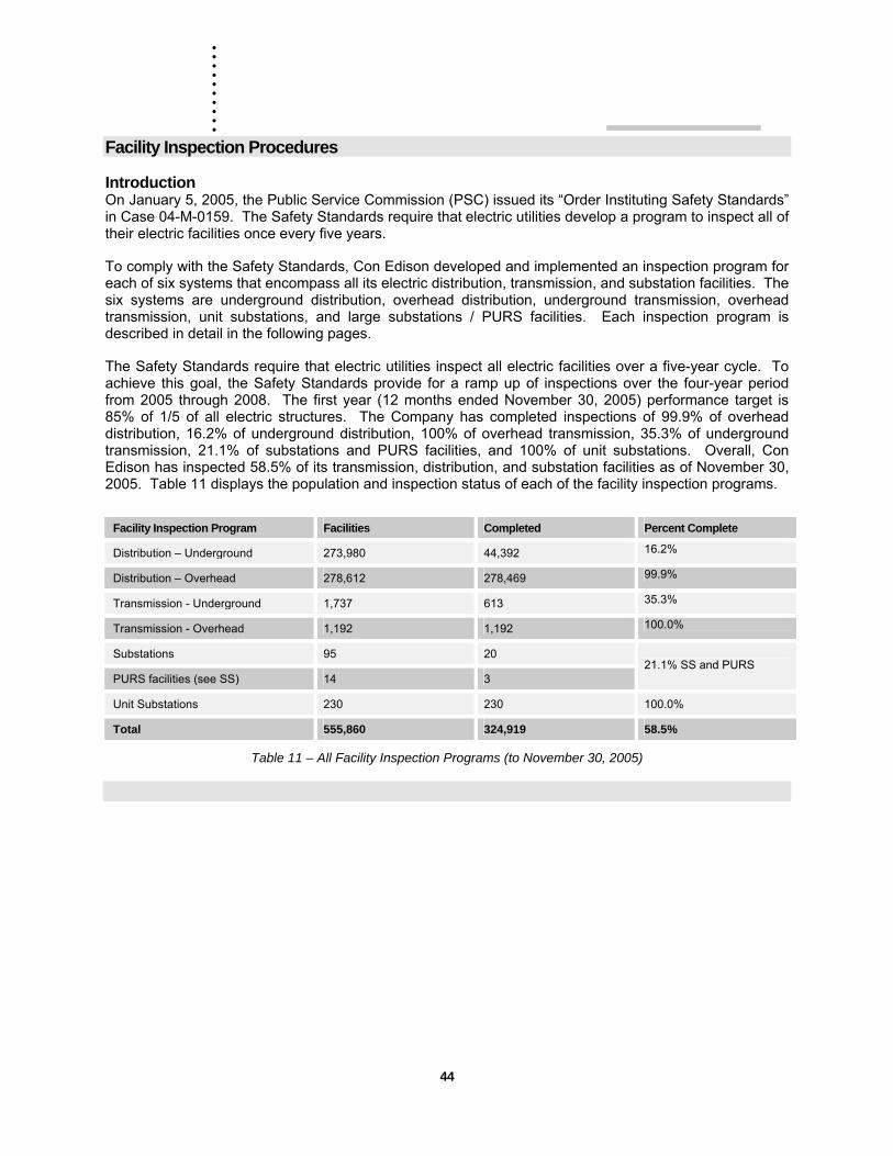
. . . . . . .. . .
44
Facility Inspection Procedures
Introduction On January 5, 2005, the Public Service Commission (PSC) issued its “Order Instituting Safety Standards” in Case 04-M-0159. The Safety Standards require that electric utilities develop a program to inspect all of their electric facilities once every five years.
To comply with the Safety Standards, Con Edison developed and implemented an inspection program for each of six systems that encompass all its electric distribution, transmission, and substation facilities. The six systems are underground distribution, overhead distribution, underground transmission, overhead transmission, unit substations, and large substations / PURS facilities. Each inspection program is described in detail in the following pages.
The Safety Standards require that electric utilities inspect all electric facilities over a five-year cycle. To achieve this goal, the Safety Standards provide for a ramp up of inspections over the four-year period from 2005 through 2008. The first year (12 months ended November 30, 2005) performance target is 85% of 1/5 of all electric structures. The Company has completed inspections of 99.9% of overhead distribution, 16.2% of underground distribution, 100% of overhead transmission, 35.3% of underground transmission, 21.1% of substations and PURS facilities, and 100% of unit substations. Overall, Con Edison has inspected 58.5% of its transmission, distribution, and substation facilities as of November 30, 2005. Table 11 displays the population and inspection status of each of the facility inspection programs.
Facility Inspection Program Facilities Completed Percent Complete
Distribution – Underground 273,980 44,392 16.2%
Distribution – Overhead 278,612 278,469 99.9%
Transmission - Underground 1,737 613 35.3%
Transmission - Overhead 1,192 1,192 100.0%
Substations 95 20
PURS facilities (see SS) 14 3 21.1% SS and PURS
Unit Substations 230 230 100.0%
Total 555,860 324,919 58.5%
Table 11 – All Facility Inspection Programs (to November 30, 2005)
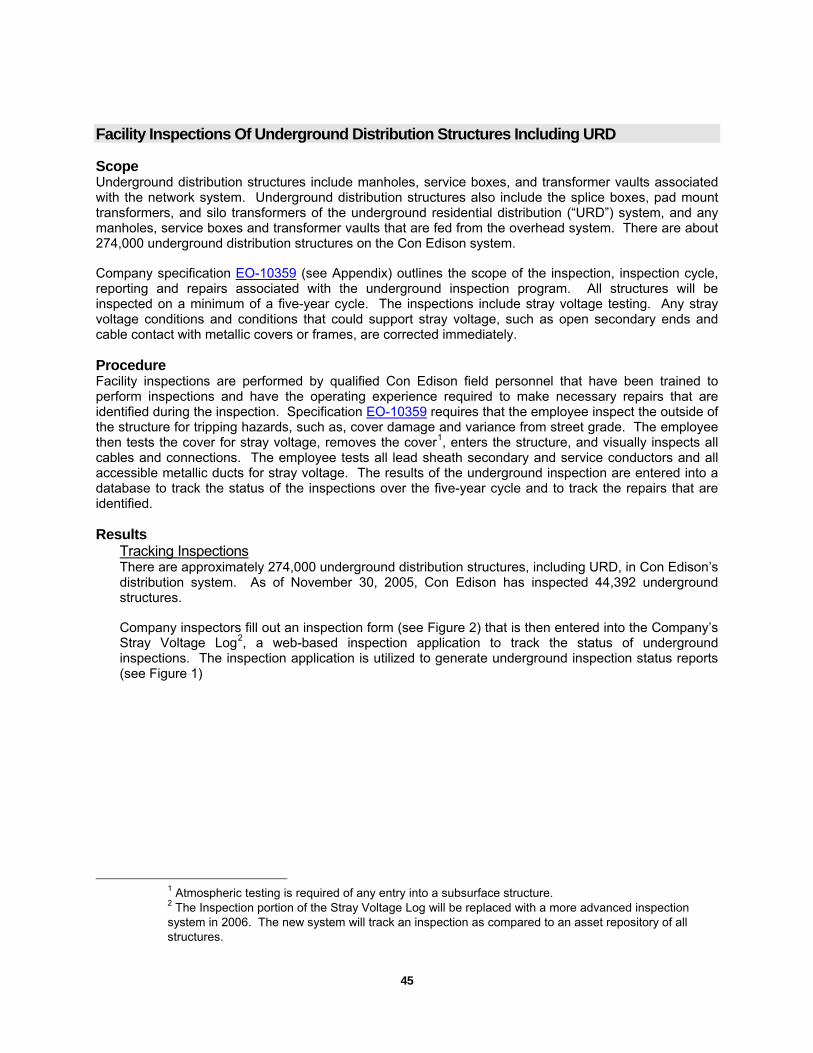
45
Facility Inspections Of Underground Distribution Structures Including URD
Scope Underground distribution structures include manholes, service boxes, and transformer vaults associated with the network system. Underground distribution structures also include the splice boxes, pad mount transformers, and silo transformers of the underground residential distribution (“URD”) system, and any manholes, service boxes and transformer vaults that are fed from the overhead system. There are about 274,000 underground distribution structures on the Con Edison system.
Company specification EO-10359 (see Appendix) outlines the scope of the inspection, inspection cycle, reporting and repairs associated with the underground inspection program. All structures will be inspected on a minimum of a five-year cycle. The inspections include stray voltage testing. Any stray voltage conditions and conditions that could support stray voltage, such as open secondary ends and cable contact with metallic covers or frames, are corrected immediately.
Procedure Facility inspections are performed by qualified Con Edison field personnel that have been trained to perform inspections and have the operating experience required to make necessary repairs that are identified during the inspection. Specification EO-10359 requires that the employee inspect the outside of the structure for tripping hazards, such as, cover damage and variance from street grade. The employee then tests the cover for stray voltage, removes the cover1, enters the structure, and visually inspects all cables and connections. The employee tests all lead sheath secondary and service conductors and all accessible metallic ducts for stray voltage. The results of the underground inspection are entered into a database to track the status of the inspections over the five-year cycle and to track the repairs that are identified.
Results Tracking Inspections There are approximately 274,000 underground distribution structures, including URD, in Con Edison’s distribution system. As of November 30, 2005, Con Edison has inspected 44,392 underground structures.
Company inspectors fill out an inspection form (see Figure 2) that is then entered into the Company’s Stray Voltage Log2, a web-based inspection application to track the status of underground inspections. The inspection application is utilized to generate underground inspection status reports (see Figure 1)
1 Atmospheric testing is required of any entry into a subsurface structure. 2 The Inspection portion of the Stray Voltage Log will be replaced with a more advanced inspection system in 2006. The new system will track an inspection as compared to an asset repository of all structures.
. . . . . . .. . .
46
Figure 1
Figure 2
Repairs Required repairs resulting from underground inspection are also recorded in the Stray Voltage Log. These repairs are classified in three categories:
Tier 1 – Repair immediately. Tier 1 – Schedule for follow-up repairs. Tier 2 – Replace as part of the Secondary Rebuild Program.
The category “Tier 1 – Repair Immediately” includes a stray voltage, cable in contact with cover, and open secondary ends. Each of these cases is a public safety concern and is repaired at the time of discovery.
The category “Tier 1 – Schedule for follow-up repairs” includes damaged neutral cables and connections, defective sump pumps, and damage to the structure cover. These repair items can be initiated at the time of discovery or scheduled for a follow-up repair.
The category “Tier 2 – Replace as part of the Secondary Rebuild Program” is used to identify items such as secondary main replacement, service replacement, and structure conductor upgrades (SCU). These items are capital improvements to the secondary system that will be scheduled and prioritized based on the overall performance of all structures on the associated M&S plate.
Quality Assurance Measures Instituted SSA created a quality assurance program, EO-10315 (Quality Assurance Of The Stray Voltage And Periodic Distribution Structure Safety Inspection Programs), to ensure that the underground structure
47
inspections are performed in accordance with the Safety Standards and Con Edison’s specifications. The reliability and error design parameters used were:
95% reliability within a ±10% relative precision level and satisfy established industry sample design criteria.
400 quality assurance audits are required to achieve a 95% confidence rate with a ±10% overall error that the inspections were conducted in accordance with Company specifications. In total, Con Edison performed 492 quality assurance audits of the underground inspections program, well above the 400 audits required for a 95% confidence rate. These quality assurance comprised of post work and work in progress audits.
Random Quality Assurance Audits – Underground Inspections The “Random Quality Assurance Audits – Underground Inspections” are audits of completed inspections. Con Edison employees from the regional quality assurance sections conduct the audits for each of the Company’s operating regions. These employees are experienced cable splicers and mechanics that have been trained in the facility inspection and the quality assurance specifications.
The completed inspections chosen for audit were randomly selected from facility inspections completed during the prior week. The quality assurance personnel performed a complete inspection of the selected facilities and compared the results to the inspection performed the previous week. Deficiencies identified during audits have been communicated to field crew supervisors who have been required to reinforce inspection procedures with field crews.
Work in Progress – Underground Inspections In addition to the 462 post-work audits, quality assurance personnel performed 30 work-in-progress quality assurance inspections for the underground structure inspection program. The scope of the audit includes meeting a field crew on location, having the crew demonstrate its understanding of the inspection requirements by performing the inspection and completing the inspection form (see Figure 2.) The quality assurance personnel then give feedback to the employees on their performance and record keeping. Each of these work-in-progress audits is recorded as an on-the-job training session.
Training Training for the underground structure inspection program began in December of 2004. The managers of the Secondary System Analysis section of Distribution Engineering conducted train-the-trainer sessions in each of the major workout locations. The participants included the managers, planners, and supervisors of the crews that would be performing the inspections. The training included a presentation that described:
The January 2004 stray voltage fatality The Safety Standards scope of the inspection Completing the inspection form Status of inspections to annual goal Repairs pending Accounting of the inspection Performance mechanism Secondary rebuild program
Ongoing training presentations have included quality assurance inspection findings.
. . . . . . .. . .
48
Facility Inspections Of Overhead Distribution Structures
Scope Overhead distribution structures, i.e., poles and pole-mounted equipment, are associated with both the non-network and network system. Con Edison or Verizon generally owns the poles, with a small subset owned by individual customers. Con Edison has conducted a complete inventory of all poles and their corresponding attachments to facilitate stray voltage testing and facility inspections. There are 278,612 poles on the Con Edison system. All of these poles and attachments will be inspected on a minimum of a five-year cycle.
Procedure The inspection of overhead distribution structures is detailed in the contractor request for proposal (RFP) and specification EO-10336 (Overhead System Inspection And Repair Priority Procedure). The RFP outlines the scope of the inspection, the five-year inspection cycle, reporting and repairs associated with the inspection.
Contractors perform the overhead facility inspections. The facility inspection is a visual inspection that is performed from the ground. The inspection entails observing the pole for obvious structural defects such as large cracks or splits. The contractor then observes the pole guys, the aerial cable and joints, and the pole equipment (crossarms, pin insulators, braces, transformers, reclosers, regulators, capacitor banks, sectionalizers, surge arresters and their connections, switches, tie wires, standpipes, secondary racks, wildlife protectors, riser cable straps, tree molding, ground wire connections) for defects. The contractor also observes if there is limited vegetation clearance.
Results The results of the overhead inspection are entered into a database to track the status of the inspections over the five-year cycle and to track the repairs required.
Tracking Inspections There are 278,612 overhead distribution poles with Con Edison equipment attachments. Con Edison inspected 278,469 (99.9%) of its overhead facilities in 2005.
The Overhead inspection program is managed from an Access database created from an extract of the corporate mapping system that was used as the baseline for all inspections. The database was given to a contractor whose field forces performed the overhead inspections from March through October 2005.
The contractor utilized hand-held computers to record the time and date of the inspection and any deficiencies identified. The data from the handheld was uploaded to the database. To ensure that all poles were inspected, the contractor was instructed to follow a pole line even when the corporate map indicated that the line ended.
Repairs Deficiencies identified on inspection are organized into two categories – emergency and non-emergency. Emergency repairs included stray voltage, dielectric fluid leaks, and wires down. The contractor manned each deficiency categorized as an emergency continuously until relieved by Con Edison. Con Edison completed repairs to all emergency conditions.
Quality Assurance Measures Instituted Distribution Engineering created a quality assurance program to ensure the overhead structure inspections are performed in accordance with the Safety Standards and Con Edison’s specifications. The reliability and error design parameters used were:
49
95% reliability within a ±10% relative precision level and satisfy established industry sample design criteria.
400 quality assurance audits are required to achieve a 95% confidence rate with a ±10% overall error that the inspections were conducted in accordance with Company specifications. In total, Con Edison performed 566 quality assurance audits of the overhead inspection program, well above the 400 audits required for a 95% confidence rate. These 566 quality assurance audits are comprised of two categories “Random Quality Assurance Audits – Overhead Inspections” and “Work in Progress – Overhead Inspections.”
Random Quality Assurance Audits – Overhead Inspections The random quality assurance audits consisted of randomly selected completed inspections. Qualified Con Edison employees performed the inspection. The quality assurance audit consisted of a complete re-inspection by the Con Edison employee and a comparison to the results obtained by the contractor. When discrepancies were identified, the contractor was notified to correct the discrepancy and notify its field forces of the discrepancy for training purposes. Con Edison conducted 553 post work inspections and identified 39 inspections with discrepancies such as failure to identify broken tie wires and damaged anchor guys.
Work in Progress – Overhead Inspections A qualified Con Edison employee performed the work in progress quality assurance audits. Con Edison met contractor field personnel on location and observed their performance of the overhead inspection. Con Edison performed 13 work in progress quality assurance audits and identified no discrepancies.
Training Con Edison developed a training presentation that was delivered to the contractor management personnel. The training included identifying pole attachments by owner (Verizon, cable television, fire departments, streetlights, and Con Edison) and identifying defects in Con Edison attachments. The contractors were then responsible to train their field inspectors.
. . . . . . .. . .
50
Overhead Transmission Facility Inspections
Scope Con Edison personnel from its Transmission Line Maintenance (“TLM”) organization conducted inspections of the Company’s population of 1,192 overhead transmission towers and poles in accordance with Con Edison procedure OP-420-3, Con Edison’s Overhead Transmission Line Ground Patrol Standard (see Appendix). OP-420-3 defines the requirements of the ground patrol. All major components of the overhead system including right-of-way, structures, and conductors/shield wires were inspected during the ground patrol inspections. The towers and poles and their surrounding fences were tested for stray voltage during the ground patrols. Reported conditions are maintained in a database and addressed in accordance with Con Edison’s established maintenance programs.
Procedure Con Edison procedure OP-420-3 was revised to meet the requirements of the Safety Standards. Overhead transmission towers are ordinarily inspected by ground patrol twice a year – once in the spring and a second time in the fall. The spring patrol assesses damage to facilities, rights-of-way, and access roads caused during the winter and spring runoff. The fall patrol ensures the lines are in proper condition to withstand the winter storms. Con Edison transmission line maintenance employees perform these inspections.
The inspection consists of a visual evaluation from the ground to evaluate encroachment of the right-of-way, access roads damage, structural damage to the tower such as bent or broken supporting members, bird nests, defective grounding, damaged conductors, damaged insulators, vegetation clearance, etc.
Results The results of the overhead transmission inspections are entered into a database to track the status of the inspections and required repairs.
Tracking Inspections All overhead transmission inspections are entered into a database that records information such as the date of the inspection, defects identified, and the inspector’s name. This database is also used to track the required repairs.
Repairs The repair work is prioritized and corrective maintenance is performed accordingly. For example, emergency work (e.g. broken shield wire) is performed immediately, and low priority work (e.g. minor road repair) is performed on a routine basis.
Quality Assurance Measures Instituted In accordance with OP-420-3, a planner in TLM, who has knowledge and expertise in overhead transmission, but who did not perform or directly supervise the inspections, conducted fifty quality assurance inspections at locations on various transmission lines. The quality assurance for stray voltage and the quality assurance for the field inspections were performed concurrently by the same person on the fifty structures. The quality assurance audit consisted of a complete re-inspection by the Con Edison employee and a comparison to the results from the initial inspection performed by the crew.
The quality assurance inspections yielded results that were either identical to those of the initial inspection, or where discrepancies did exist, were generally minor in nature. While the discrepancies were considered to be minor, efforts will be made to improve the effectiveness of the inspections by reviewing the process with the inspectors prior to the 2006 inspection cycle and highlighting some of these discrepancies.

51
Training All Transmission Line Maintenance personnel who conduct these inspections are familiar with the infrastructure and regularly perform tasks to install, maintain, and repair it. They are trained in the inspection protocols through career path training. This training is refreshed as required.
. . . . . . .. . .
52
Underground Transmission Facility Inspections
Scope The 1737 underground transmission manholes are inspected by Con Edison personnel in accordance with Company specification CE-SS-6830 (Low And Medium Feeder Pressure Periodic Inspection Procedure) and CE-SS-6045 (Inspection And Preventive Maintenance And Stray Voltage Testing Of Pipe Type Cable Systems) depending on the type of facility being inspected. This specification outlines the scope of the inspection, inspection cycle, reporting and repairs associated with the inspection. Con Edison inspected 613 of the 1737 underground transmission manholes in 2005.
Procedure Facilities associated with pipe type cable system must be inspected in accordance with Con Edison specification CE-SS-6045. This specification states the inspection criteria applicable to such facilities, and provides a summary of the inspection process. These inspections include, but are limited to, the following facilities:
• Manholes (Normal Joint, Semi-Stop joint, Full Stop Joint (including circulation line valve), Diffusion Chamber and Clean Out etc.)
• Risers and exposed pipe sections on bridges
• Risers and exposed pipe sections in tunnels
• Valve Boxes, Vent Chambers, Freeze Pits and Thermal Probe Pits
• Potheads
Facilities associated with low and medium pressure fluid filled cable system must be inspected in accordance with Con Edison specification CE-SS-6830. This specification states the inspection criteria applicable to such facilities, and provides a summary of the inspection process. These inspections include, but are limited to, the following facilities:
• Manholes
• Joints
• Potheads
• Reservoirs
• Reservoir Alarm Relays
• Bonds
Results Con Edison inspected 613 of the 1737 underground transmission manholes in 2005. The results of the underground transmission inspection are entered into the work management system (MAXIMO) to track the status of the inspections and required repairs.
Tracking Inspections Inspection results are recorded on a form detailed in the referenced specifications, and entered into the work management system (MAXIMO). Each MAXIMO record includes the date of the inspection, defects identified, and the inspector’s name. This database is also used to track the required repairs.
53
Repairs The repair work is prioritized and corrective maintenance is performed accordingly. For example, emergency work (e.g. leaking pipe) is performed immediately, and low priority work (e.g. missing feeder tag) is performed on a routine basis
Quality Assurance Measures Instituted Company specifications CE-SS-6830 (Low And Medium Feeder Pressure Periodic Inspection Procedure) and CE-SS-6045 (Inspection And Preventive Maintenance And Stray Voltage Testing Of Pipe Type Cable Systems) require that quality assurance inspections of randomly selected transmission manholes be performed. These randomly selected manholes are re-inspected or re-tested by trained and knowledgeable employees who did not perform or directly supervise this work. In accordance with these specifications, five low/medium pressure cable system transmission manholes and 12 pipe type cable system transmission manholes were re-inspected in 2005, with results entered into the work management system (MAXIMO).
The quality assurance inspections yielded results that were either identical to those of the initial inspection, or where discrepancies did exist, they were generally minor in nature. While the discrepancies were considered to be minor, efforts will be made to improve the effectiveness of the inspections by reviewing the process with the inspectors prior to the 2006 inspection cycle and highlighting some of these discrepancies.
Training All Transmission Operations personnel who conduct these inspections are familiar with the infrastructure and regularly perform tasks to install, maintain, and repair it. They are trained in the inspection protocols through career path training. This training is refreshed as required.
. . . . . . .. . .
54
Substation Facility Inspections
Scope Inspections of Con Edison’s 95 substations and 14 public utility regulatory station (PURS) facilities are performed in accordance with the Company’s Substations Operations (SSO) procedure 0800-0038/00, Substations Stray Voltage Testing And Station Inspection (see Appendix). This procedure defines the requirements for substation and PURS facility inspections. (A PURS facility regulates the temperature of fluids used for cooling pipe-type transmission feeders.)
Procedure The procedure entails a careful visual safety and reliability examination of substation and PURS cooling plant equipment for conditions that have the potential to cause or lead to safety hazards or failure of the equipment. Qualified substation personnel perform these inspections. All equipment in a substation or PURS cooling plant will be inspected by visual examination once every five years, and at least 20% of the substations and PURS cooling stations will be inspected each year. These inspections are separate and in addition to the periodic visual and/or maintenance functions that SSO performs on a periodic basis through compliance inspections such as battery room inspections, deluge room inspections, quarterly pump house, circulation plant and PURS inspections, pothead inspections, overhead tower inspections, and load board inspections.
Inspections are conducted according to inspection rounds for the “equipment categories” at each substation station or PURS cooling plant as established in MAXIMO, SSO’s work management system. The equipment categories to be visually inspected are battery room, deluge room, pump house, circulation plant, PURS, pothead, overhead tower, load board, control rooms, relay cubicles (interior and exterior), alarm panels, circuit breaker cabinets (transmission and distribution voltage levels), transformers, station yards and interior switch rooms.
The individual equipment within each equipment category at each station will be visually inspected for any condition that has the potential to cause or lead to safety hazards or failure of the equipment. For example, all equipment within a relay cubicle will be visually inspected. Among the conditions to be identified are exposed conductors, corrosion, frayed/damaged insulation, foreign material intrusion, water leaks, and grounding connections.
Structures containing equipment, whether locked or not, must be opened and the equipment visually inspected. Disassembly of panels and cubicles is not required, only doors and openings normally designed to be accessible and operated during operations or maintenance are required to be opened. Sealed structures will not be opened.
Results Con Edison inspected 20 substations of its 95 substations and 3 of its 11 PURS cooling facilities in 2005. In total 21.1% of the substations and PURS facilities were inspected.
Tracking Inspections The results of the inspection of each equipment category at a substation or PURS cooling plant are recorded in MAXIMO and each equipment deficiency is recorded. An associated Auto Tour round (job plan) is completed, identifying the inspection results.
All environmental or safety problems are immediately reported to the station operator who notifies the Control Center Shift Manager. All other items found during the inspection are recorded in MAXIMO. A new MAXIMO work order is generated to make the appropriate repairs.
55
Repairs The inspection of the 20 substations of its 95 substations and 3 of its 11 PURS cooling facilities included 637 separate inspection groups. The required repairs include items such as replacing lighting, replacing covers on electrical junction boxes, and general station cleanup.
Quality Assurance Measures Instituted Substation Operations’ quality assurance program consists of periodic document reviews and field observations to ensure that 100% of the required stray voltage tests and a minimum of 20% of the Safety and Reliability Inspections will be completed by November 30 of each year and that the testing and inspections are conducted properly.
The quality assurance audits were performed by members of the SSO MAXIMO group and consisted of a documents search, records review, as well as physical critical visual inspection. Critical visual inspection quality assurance audits were performed at two PURS locations and one substation facility in Queens. Separate inspection records were created for each quality assurance audit. The audits found no deficiencies in the original inspections. In addition, all inspection and follow-up work order documentation was reviewed. The audit indicated that follow-up work orders (to make repairs identified during the visual inspections) were not completed at five substations. These work orders were entered into our work management system and processed by appropriate personnel. In the remaining stations, work orders for repairs identified during the inspections had been completed. All personnel were retrained on proper reporting and referral of repairs identified during facility inspections.
Training Employee’s are trained and demonstrate the ability to perform facility Inspections following Company specifications and safety procedures through training module CSG0020 (Stray Voltage Testing and Critical Visual Safety Inspections). The training includes the reasons for facility inspections, PSC Case 04-M-0159 Safety Standards requirements, safety concerns and conditions, personnel protective equipment, facility inspection criteria, and reporting.
. . . . . . .. . .
56
Unit Substation Facility Inspections
Scope Existing Con Edison procedure EO-10790 (Inspection And Maintenance Schedule For 4 kV Unit And Multi-Bank Substation Transformers And Switchgear) complies with the Safety Standards’ inspection requirements. The specification is a guide for 4 kV Unit Substation maintenance personnel who operate and maintain the 230 Multi-Bank and Unit Substation transformers and associated switchgear. It is formulated from industry standards, current Company practices, and equipment manufacturers’ recommendations with the objective of optimizing equipment operation.
Procedure Qualified substation maintenance and operational personnel perform the facility inspections pursuant specification EO-10790. The inspections are performed every two months – more frequently than required by the Safety Standards. The inspection includes circuit breakers, transformer and feeder circuit breakers, low voltage circuit breakers, tap changers, primary (de-energized tap changer), reactors, voltage regulators, cooling equipment, gauges and meters, control batteries, battery charger, nitrogen equipment and supply, transformer silica gel breathers, thermostat and heaters, station light and power, control wiring and circuits, protective relays, unit substation automation (USA), ground and test device, and environmental systems.
Results In 2005, Con Edison inspected all 230 unit substations.
Tracking Inspections Periodic inspection of all unit and multi-bank substations for general station conditions are completed every two months. Completed inspection forms are submitted to and retained by the local supervisor who manages the required repairs.
Repairs These inspections yielded repairs will be processed based on priority, severity of repairs, and other work. They will be incorporated into facility maintenance or corrective maintenance activities. The defects: include defective light bulbs, landscaping/station clean-ups, defective telephones, low nitrogen cylinders, defective L&P transformer, station one line diagrams that need updating, Hi-Lo oil levels, stations need painting, etc. If the problem is of a serious nature, the inspector calls a supervisor for immediate response. If the defects are of a lesser nature, the supervisors prioritize the defects for repair.
Quality Assurance Measures Instituted SSA performed a quality assurance re-inspection on 2% of the facility inspections of unit substations. Six unit substations were randomly selected from the 230 unit substations. The findings of the quality assurance re-inspection were compared to the original inspection of each unit substation. All six of the quality assurance audits demonstrated acceptable inspections.
Training All substation personnel that perform facility inspections receive the required training during their career path training to the various titles within substation maintenance and operations.
57
Part Four – Public Service Commission Performance Mechanism
2005 Stray Voltage Detection and Electric Facility Inspection Report
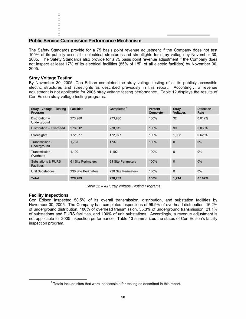
. . . . . . .. . .
58
Public Service Commission Performance Mechanism
The Safety Standards provide for a 75 basis point revenue adjustment if the Company does not test 100% of its publicly accessible electrical structures and streetlights for stray voltage by November 30, 2005. The Safety Standards also provide for a 75 basis point revenue adjustment if the Company does not inspect at least 17% of its electrical facilities (85% of 1/5th of all electric facilities) by November 30, 2005.
Stray Voltage Testing By November 30, 2005, Con Edison completed the stray voltage testing of all its publicly accessible electric structures and streetlights as described previously in this report. Accordingly, a revenue adjustment is not applicable for 2005 stray voltage testing performance. Table 12 displays the results of Con Edison stray voltage testing programs.
Stray Voltage Testing Program
Facilities Completed3 Percent Complete
Stray Voltages
Detection Rate
Distribution – Underground
273,980 273,980 100% 32 0.012%
Distribution – Overhead 278,612 278,612 100% 99 0.036%
Streetlights 172,977 172,977 100% 1,083 0.626%
Transmission - Underground
1,737 1737 100% 0 0%
Transmission - Overhead
1,192 1,192 100% 0 0%
Substations & PURS Facilities
61 Site Perimeters 61 Site Perimeters 100% 0 0%
Unit Substations 230 Site Perimeters 230 Site Perimeters 100% 0 0%
Total 728,789 728,789 100% 1,214 0.167%
Table 12 – All Stray Voltage Testing Programs
Facility Inspections Con Edison inspected 58.5% of its overall transmission, distribution, and substation facilities by November 30, 2005. The Company has completed inspections of 99.9% of overhead distribution, 16.2% of underground distribution, 100% of overhead transmission, 35.3% of underground transmission, 21.1% of substations and PURS facilities, and 100% of unit substations. Accordingly, a revenue adjustment is not applicable for 2005 inspection performance. Table 13 summarizes the status of Con Edison’s facility inspection program.
3 Totals include sites that were inaccessible for testing as described in this report.
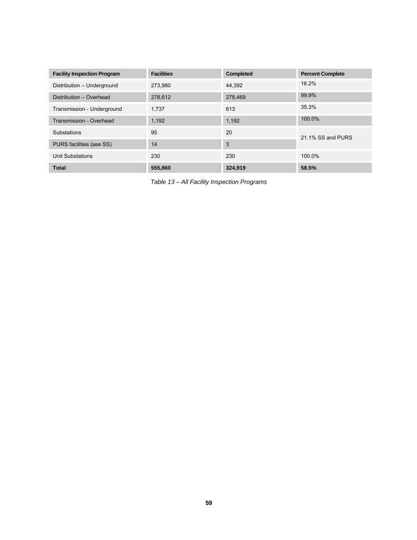
59
Facility Inspection Program Facilities Completed Percent Complete
Distribution – Underground 273,980 44,392 16.2%
Distribution – Overhead 278,612 278,469 99.9%
Transmission - Underground 1,737 613 35.3%
Transmission - Overhead 1,192 1,192 100.0%
Substations 95 20
PURS facilities (see SS) 14 3 21.1% SS and PURS
Unit Substations 230 230 100.0%
Total 555,860 324,919 58.5%
Table 13 – All Facility Inspection Programs

. . . . . . .. . .
60
This page is intentionally left blank.
61
Part Five – Certification of Stray Voltage Testing and Facility Inspection Programs
2005 Stray Voltage Detection and Electric Facility Inspection Report
. . . . . . .. . .
62
Certification of Stray Voltage Testing and Facility Inspection Programs
The due diligence and test-completion certification of the Con Edison’s officer responsible for overseeing the Company’s Stray Voltage Testing Program is provided in the Appendix.
The due diligence and inspection-completion certification of the Con Edison’s officer responsible for overseeing the Company’s Facility Inspection Program is provided in the Appendix.
. . . . . .. . . .
. . . . . . . . . .
Part Six – Analysis of Stray Voltage Testing Results
2005 Stray Voltage Detection and Electric Facility Inspection Report
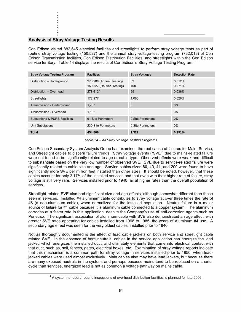
. . . . . . .. . .
64
Analysis of Stray Voltage Testing Results
Con Edison visited 882,545 electrical facilities and streetlights to perform stray voltage tests as part of routine stray voltage testing (150,527) and the annual stray voltage-testing program (732,018) of Con Edison Transmission facilities, Con Edison Distribution Facilities, and streetlights within the Con Edison service territory. Table 14 displays the results of Con Edison’s Stray Voltage Testing Program.
Stray Voltage Testing Program Facilities Stray Voltages Detection Rate
Distribution – Underground 273,980 (Annual Testing) 150,527 (Routine Testing)
32 108
0.012% 0.071%
Distribution – Overhead 278,6124 99 0.036%
Streetlights 172,977 1,083 0.626%
Transmission - Underground 1,737 0 0%
Transmission - Overhead 1,192 0 0%
Substations & PURS Facilities 61 Site Perimeters 0 Site Perimeters 0%
Unit Substations 230 Site Perimeters 0 Site Perimeters 0%
Total 454,809 1,322 0.291%
Table 14 – All Stray Voltage Testing Programs
Con Edison Secondary System Analysis Group has examined the root cause of failures for Main, Service, and Streetlight cables to discern failure trends. Stray voltage events (“SVE”) due to mains-related failure were not found to be significantly related to age or cable type. Observed effects were weak and difficult to substantiate based on the very low number of observed SVE. SVE due to service-related failure were significantly related to cable size and age. Service cables sized 80, 40, 41, and 200 were found to have significantly more SVE per million feet installed than other sizes. It should be noted, however, that these cables account for only 2.17% of the installed services and that even with their higher rate of failure, stray voltage is still very rare. Services installed prior to 1940 fail at higher rates than the overall population of services.
Streetlight-related SVE also had significant size and age effects, although somewhat different than those seen in services. Installed #4 aluminum cable contributes to stray voltage at over three times the rate of #6 (a non-aluminum cable), when normalized for the installed population. Neutral failure is a major source of failure for #4 cable because it is aluminum cable connected to a copper system. The aluminum corrodes at a faster rate in this application, despite the Company’s use of anti-corrosion agents such as Penetrox. The significant association of aluminum cable with SVE also demonstrated an age effect, with greater SVE rates appearing for cables installed from 1968 to 1985, the years of Aluminum #4 use. A secondary age effect was seen for the very oldest cables, installed prior to 1940.
Not as thoroughly documented is the effect of lead cable jackets on both service and streetlight cable related SVE. In the absence of bare neutrals, cables in the service application can energize the lead jacket, which energizes the installed duct, and ultimately elements that come into electrical contact with that duct, such as, soil, fences, gates, electrical boxes, etc. Examination of stray voltage reports indicate that this mechanism is a common path for stray voltage in services installed prior to 1950, when lead-jacked cables were used almost exclusively. Main cables also may have lead jackets, but because there are many exposed neutrals in the system, and perhaps because mains tend to be replaced on a shorter cycle than services, energized lead is not as common a voltage pathway on mains cable.
4 A system to record routine inspections of overhead distribution facilities is planned for late 2006.
. . . . . .. . . .
. . . . . . . . . .
Part Seven – Stray Voltage Initiatives
2005 Stray Voltage Detection and Electric Facility Inspection Report
. . . . . . .. . .
66
Stray Voltage Initiatives
Research and Development Con Edison’s Research and Development (R&D) department is involved in initiatives that may lead to a reduction in stray voltage or better detection techniques. This section describes several of the more promising programs.
Mobile Stray Voltage Detector The project has developed a vehicular sensor/system for detecting the presence of stray voltages on manhole covers, gratings, service boxes, light poles and other structures while driving over roadways. The development includes a three-axis version, optimization of detector sensitivity for field conditions, improved design of the capture, analysis and alarm electronics and prototype testing in field conditions. Con Edison has procured five mobile stray voltage detection (SVD) systems from Sarnoff Corporation. These SVD employ three-dimensional electric field sensors to detect stray voltages or unshielded electric cable.
Composite Covers If a low voltage cable comes in contact with the metallic cover of a distribution structure, a stray voltage can be created if the cable insulation fails. A composite or non-metallic structure cover can provide additional electrical insulation to prevent an insulation failure within the structure from becoming a stray voltage on the surface.
There are no existing AASHTO/DOT regulations governing the use of composites manhole covers. Test protocols to establish the validity and feasibility of composite manhole covers in roadways are being investigated. Multiple composite material designs are considered including possible composite-metal combos for testing and validation. The objective of the tests is to determine how well composites withstand traffic loading while withstanding stray currents and exposure to elevated temperatures (such as steam), weather, and chemicals in the environment.
Manhole Cover Monitoring System This project seeks to develop a sensor/system for real time detection of the presence of stray voltages on manhole covers, gratings, service boxes, light poles and other structures. The system will have RF communication capabilities.
The project has developed a sensor system and communication channel for detecting the presence of stray voltages on transformer gratings. This is an active program that will begin installing monitors in January of 2006 in transformer vaults where communication systems already exist. The expected completion date for 1,887 vaults is January of 2009.
Arcing Signature Electrification events may be associated with arcing faults on the secondary network mains and / or services. Prior work sought a method of detecting such faults by staging arcing faults, measuring the resultant voltage and current waveforms, and determining if microprocessor network protector relays could detect and discriminate the event. The results showed some signature that could be recognized by an enhanced relay, but locating the source and discriminating from other electrical events proved problematic. The current project follows up on the prior work and seeks to take advantage of advances in technology.
The Canadian Electric Association (CEA) is leading a project that is limited to the detection and interruption of secondary voltage arcing faults. Secondary voltages to be considered range from 120/240V to 347/600V and include both single phase and three-phase secondary voltage distribution. The objective is to identify the technical performance parameters required for secondary voltage arcing fault detection and interruption device(s) that could be applied to overhead and underground

67
secondary service wires, and utility secondary distribution networks. (In the case of utility secondary networks, the requirement may be for detection only.)
The Electric Power Research Institute (EPRI) is managing a project that seeks to develop a design spec for several “low cost” monitoring or injection devices that could be used to detect arcing fault on underground secondary distribution systems. If successful, a second phase will seek to develop the mechanism for arcing fault localization and communication.

. . . . . . .. . .
68
This page is intentionally left blank.
. . . . . .. . . .
. . . . . . . . . .
Part Eight – Future Improvements
2005 Stray Voltage Detection and Electric Facility Inspection Report
. . . . . . .. . .
70
Future Improvements
Con Edison has initiated several programs and work practices to enhance stray voltage detection and data management, and maximize the number of facility inspections. This section reviews these improvements.
Shunt Resistor Overhead lines are not shielded and can induce voltages on metallic surfaces. These voltages are normally not harmful, and they do not involve a failed component of the distribution system.
The HD stray voltage indicator and a digital voltmeter can falsely indicate a stray voltage condition in the presence of induced voltage.
A digital voltmeter’s very high input impedance is designed not to affect the circuit being tested. The design has the disadvantage of being unable to distinguish a stray voltage capable of delivering an electric shock, from an induced voltage with no current-carrying capacity. A shunt resister can be used in conjunction with the Fluke voltmeter to determine whether the voltage is produced by current (presenting the possibility of electric shock) or is induced (harmless).
We have developed a shunt resistor to be used in combination with the Fluke voltmeter when a potential stray voltage has been identified on the overhead system. The step-by-step procedure is described in the Appendix.
Visual Secondary Targeting (VST) The VST rolled out in the fall of 2005 and was very successful in allowing Con Edison to maximize facility inspections and minimize repeat inspections. The VST is an Intranet, browser based product that provides graphic displays of the Secondary Targeting Indices and associated data utilizing scalable vector graphics (SVG) technologies. The structures and associated land base are network based and extracted from the corporate mapping system. Facility inspections and other data are provided at the network, M&S plate, and structure level. The VST includes navigation tools such as:
• Navigation by network will be provided graphically or from a pick list.
• Navigation by M&S plate from either the Borough or Network view.
• Structures will be visible and selectable at the M&S level.
• Zoom in, Zoom out, and Zoom in by will be provided.
Data available on the graphic displays is retrievable by user selected date ranges and include:
• ECS (manhole and cable incidents)
• Stray Voltage & Inspection results and status
Inspection System Development This project was initiated in 2004 to track and report on structure safety inspections. The goal of this project is to implement an integrated suite of compliance inspection applications for Electric Operations. These applications will take the place of several existing applications built on the Mainsaver platform to track inspections (underground structures and network transformers) and resulting repair work.
The project will be approached in three phases:
1. Build an inspection infrastructure and asset repository to support scheduling, design, recording and reporting of inspections.
71
2. Develop an integrated route sheet for all inspection and construction work (now in eTRAC).
3. Implement an integrated process across systems to create and complete work.
The initial phase is broken into three sub-phases relating to underground structures, overhead structures (including streetlights), and equipment. The first sub-phase is scheduled to start in 2005, while the other two sub-phases are scheduled to start in 2006 and 2007.
Field data capture will involve the use of suitable laptops incorporating an application that can work wirelessly or detached from a data communications network. A generic application will be provided to allow for the creation of inspection templates and completion of inspection records on the field devices. An inspection-scheduling engine will be provided as well as an end user interface for the assignment of inspection work and the generation of reports. The system will allow safety inspection templates (based on Distribution Engineering specifications) to be designed and implemented by end users for data capture.
Asset data will be profiled, quality checked, cleansed and loaded from existing databases – CIMOES, CINDE, mapping systems and the Stray Voltage Log. A process for creating new assets will be established.
The second phase will concentrate on providing an integrated route sheet for all inspection and construction work. It will allow work in the inspection system and eTRAC to be planned, scheduled and assigned through one user interface.
The final phase will allow for the integrated creation of work in the source systems (such as DOCS and ECS) based on the results of an inspection. It will also allow for the closeout of work in the source systems based on completion information in the integrated route sheet.
Data Management A challenging aspect of the stray voltage testing and facility inspection programs is managing large volumes of data. Con Edison has performed three rounds of stray voltage testing, and has improved data management in each round.
The first round (January - March 2004) consisted of printing the M&S plates (maps) showing electric structures and sending them out to the field to identify and locate structures for testing. Each structure was then marked on the plate to indicate that it was tested. The map was then returned to the office where it was verified that each structure on the plate had an indication that it had been tested. The office personnel compared the marked up M&S plate to an extract from the corporate mapping system. This process could lead to the M&S plate being returned to the field several times for subsequent testing if a discrepancy was identified.
In the second round (October – December 2004), Con Edison created databases from the extracts from the corporate mapping system. These databases were then given to the stray voltage testing contractors. The contractors tested the structure and indicated as such in the database. This second round still used marked up M&S plates, but the contractor was responsible for the data management. The databases were then uploaded to the central Con Edison database. This system was better, but the process to deal with no access and not found structures was not well defined.
In the third round (February - November 2005), Con Edison required electronic data collection through handheld computers and introduced bar coding of streetlights. The handheld computers were used for the overhead and streetlight testing programs. In addition, Con Edison collected the GPS coordinates for each wood pole and streetlight. The GPS coordinates will be used in subsequent testing programs to facilitate locating poles and streetlights.
. . . . . . .. . .
72
Con Edison is presently negotiating the 2006 stray voltage testing contracts, and plans to have full electronic data collection via handheld computers for the overhead, underground and streetlight testing programs. The streetlight barcodes will be scanned and the date and time of the test will be electronically captured. Also in 2006, Con Edison will do a complete inventory of the underground distribution structures including capturing the GPS coordinates of each structure. Con Edison also plans to retire the Microsoft Access databases that have been used in the previous programs and replace them with custom SQL applications running on dedicated servers.
. . . . . .. . . .
. . . . . . . . . .
Appendix
2005 Stray Voltage Detection and Electric Facility Inspection Report

. . . . . . .. . .
74
This page is intentionally left blank.
75
A: EO-5,100 (Low Voltage Detectors - Stray Voltage)
CONSOLIDATED EDISON COMPANY OF NEW YORK, INC. 4 IRVING PLACE
NEW YORK, NY 10003
PURCHASE AND TEST EO-5100 REVISION 0MANUAL NO. 6, SECTION 24 FEBRUARY 2005
LOW VOLTAGE DETECTORS - STRAY VOLTAGE
1. SCOPE
This specification details the requirements for low voltage detectors and associated test devices that are to be used for stray voltage testing.
2. APPLICATION
This specification applies to all Customer Service Regions.
3. GENERAL
Detectors covered under this specification are used to detect the presence of low voltage on various structures and components associated with the Con Edison distribution system. A separate test device shall be provided to verify the proper operation of the detector.
4. PURCHASE RECOMMENDATION
Approved manufacturer’s products for Low Voltage Detectors /Test Devices are listed in Purchase Recommendation EO-100175.
5. REQUIREMENTS
5.1 Enclosure
Materials used for the enclosures of both the low voltage detector and the associated test device shall be impact resistant and durable under the anticipated operating conditions of the devices. The assembled devices shall be constructed so as to preclude the entry of foreign material or moisture. Low voltage detector and test device enclosures shall be constructed to meet the requirements for NEMA 4 enclosures in accordance with NEMA Standards Publication 250 – 2003.
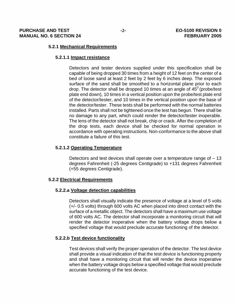
PURCHASE AND TEST -2- EO-5100 REVISION 0MANUAL NO. 6 SECTION 24 FEBRUARY 2005
5.2.1 Mechanical Requirements
5.2.1.1 Impact resistance
Detectors and tester devices supplied under this specification shall be capable of being dropped 30 times from a height of 12 feet on the center of a bed of loose sand at least 2 feet by 2 feet by 6 inches deep. The exposed surface of the sand shall be smoothed to a horizontal plane prior to each drop. The detector shall be dropped 10 times at an angle of 450 (probe/test plate end down), 10 times in a vertical position upon the probe/test plate end of the detector/tester, and 10 times in the vertical position upon the base of the detector/tester. These tests shall be performed with the normal batteries installed. Parts shall not be tightened once the test has begun. There shall be no damage to any part, which could render the detector/tester inoperable. The lens of the detector shall not break, chip or crack. After the completion of the drop tests, each device shall be checked for normal operation in accordance with operating instructions. Non-conformance to the above shall constitute a failure of this test.
5.2.1.2 Operating Temperature
Detectors and test devices shall operate over a temperature range of – 13 degrees Fahrenheit (-25 degrees Centigrade) to +131 degrees Fahrenheit (+55 degrees Centigrade).
5.2.2 Electrical Requirements
5.2.2.a Voltage detection capabilities Detectors shall visually indicate the presence of voltage at a level of 5 volts (+/- 0.5 volts) through 600 volts AC when placed into direct contact with the surface of a metallic object. The detectors shall have a maximum use voltage of 600 volts AC. The detector shall incorporate a monitoring circuit that will render the detector inoperative when the battery voltage drops below a specified voltage that would preclude accurate functioning of the detector.
5.2.2.b Test device functionality
Test devices shall verify the proper operation of the detector. The test device shall provide a visual indication of that the test device is functioning properly and shall have a monitoring circuit that will render the device inoperative when the battery voltage drops below a specified voltage that would preclude accurate functioning of the test device.
PURCHASE AND TEST -3- EO-5100 REVISION 0MANUAL NO. 6 SECTION 24 FEBRUARY 2005
5.3 Serial Number
Each detector and test device shall be assigned a unique, traceable, serial number. The serial number shall contain information on the date of manufacture.
5.4 Labeling
Detectors and testers shall be permanently, and legibly labeled with the following information: manufacturer, model number, serial number, and notation that the device operated within the specified design parameters.
5.5 Packing Slip Documentation
Each detector / test device shall come with a packing slip. The packing slip shall list the following information:
1. Serial Number 2. Date The Unit Passed The Test 3. Test Operator
5.6 Certified Test Report
A certified test report for each shipment of detectors / test devices shall be sent to the Distribution Engineering Environmental Health and Safety Manager listing the serial numbers of each detector and /or tester in the shipment and their “turn on voltage or output voltage” respectively. The Product Manager for these products or an officer of the company shall sign the report.
J.R. Martin J. Schneider Joseph R Martin(signature on file) Joseph R. Martin Manager Environmental Health and Safety Distribution Engineering REVISION 0 Initial Issue To be reviewed by 02/10
FILE: Purchase and Test Manual No. 6, Section 24, Tools
. . . . . . .. . .
76
B: EO-100,175 (Purchase Recommendation - Low Voltage Detectors For Stray Voltage)
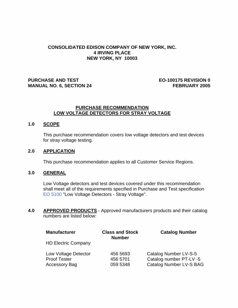
CONSOLIDATED EDISON COMPANY OF NEW YORK, INC. 4 IRVING PLACE
NEW YORK, NY 10003
PURCHASE AND TEST EO-100175 REVISION 0MANUAL NO. 6, SECTION 24 FEBRUARY 2005
PURCHASE RECOMMENDATION LOW VOLTAGE DETECTORS FOR STRAY VOLTAGE
1.0 SCOPE
This purchase recommendation covers low voltage detectors and test devices for stray voltage testing.
2.0 APPLICATION
This purchase recommendation applies to all Customer Service Regions.
3.0 GENERAL
Low Voltage detectors and test devices covered under this recommendation shall meet all of the requirements specified in Purchase and Test specification EO 5100 "Low Voltage Detectors - Stray Voltage”.
4.0 APPROVED PRODUCTS - Approved manufacturers products and their catalog numbers are listed below:
Manufacturer Class and Stock Number
Catalog Number
HD Electric Company Low Voltage Detector 456 5693 Catalog Number LV-S-5 Proof Tester 456 5701 Catalog number PT-LV -5 Accessory Bag 059 5348 Catalog Number LV-S BAG
PURCHASE AND TEST -2- EO-100175 REVISION 0MANUAL NO. 6, SECTION 24 FEBRUARY 2005
5.0 ALTERNATE MANUFACTURERS
Low voltage detectors produced by manufacturers other than those listed in paragraph 4 may be submitted to the Distribution Engineering Environmental Health and Safety Manager for evaluation. Products found acceptable will be included in subsequent revisions of this purchase recommendation.
J. Schneider Joseph R Martin (signature on file) Joseph R. Martin Manager Environmental Health and Safety Distribution Engineering REVISION:0 Initial issue To be Reviewed by 02/10
FILE: Purchase and Test Manual No. 6, Section 24 Tools

77
This page is intentionally left blank.
. . . . . . .. . .
78
C: EO-10,129 (Operation And Maintenance Of Low Voltage Detector For Stray Voltage)
CONSOLIDATED EDISON COMPANY OF NEW YORK, INC.
4 IRVING PLACE NEW YORK, NY 10003
DISTRIBUTION ENGINEERING DEPARTMENT ENVIRONMENTAL HEALTH AND SAFETY
SPECIFICATION EO–10129
REVISION 2
MAY 2005
OPERATION AND MAINTENANCE OF LOW VOLTAGE DETECTOR FOR STRAY VOLTAGE
FILE: OPERATION AND MAINTENANCE OF EQUIPMENT MANUAL NO. 1, SECTION NO. 15
TARGET AUDIENCE CON EDISON SYSTEM
NESC REFERENCE NONE
OPERATION AND MAINTENANCE OF EO-10129 REVISION 2 EQUIPMENT MAY, 2005 MANUAL NO. 1 SECTION 15
2
TABLE OF CONTENTS
PARAGRAPH DESCRIPTION PAGE 1.0 SCOPE 3 2.0 APPLICATION 3 3.0 GENERAL 3 4.0 PURCHASE RECOMMENDATION 4 5.0 OPERATING INSTRUCTIONS 4 6.0 PRELIMINARY DEVICE TESTS 5 7.0 VOLTAGE TEST 6

OPERATION AND MAINTENANCE OF EO-10129 REVISION 2 EQUIPMENT MAY, 2005 MANUAL NO. 1 SECTION 15
3
1.0 SCOPE This specification details the operation, maintenance and application of the HD Electric
LV-S-5 low voltage detector and the associated PT-L-5 proof test device. The LV-S-5 detector is used to test for stray voltage on various structures and components that are associated with the Con Edison system that are not normally energized.
2.0 APPLICATION This specification applies to all Customer Service Regions. 3.0 GENERAL 3.1 Theory Of Operation The LV-S-5 low voltage detector operates by matching a factory-preset voltage
(threshold voltage) to a voltage that is present at the tip of the detector. When the voltage at the detector tip equals or exceeds this preset voltage, the detector will provide a visual indication. Proper operation of the detector is verified prior to use by means of a proof test device. The proof test device simulates contact with an energized surface by generating a ”test voltage” that is slightly greater than the detectors preset (threshold) voltage.
3.2 Operational Conditions The LV-S-5 potential detector is designed to operate under all normally
encountered weather conditions. The device can be used in precipitation, but is not designed to be submerged in liquid.
The LV-S-5 potential detector and the PT-LV-5 proof test device are, designed to
operate over a temperature range of -13o Fahrenheit (-25o Centigrade) to +131o Fahrenheit (+ 55o Centigrade).
3.3 Voltage Detection Capabilities The LV-S-5 voltage detectors shall be used to detect AC voltages only. The LV-
S-5 voltage detector will visually indicate the presence of voltage over an operating range of 8 – 600 volts AC when placed into direct contact with the surface of a metallic object. The maximum use voltage of the LV-S-5 detector is 600 volts AC. The detector incorporates a monitoring circuit that will render the detector inoperative when the battery voltage drops below a specified voltage that would preclude accurate functioning of the detector.
OPERATION AND MAINTENANCE OF EO-10129 REVISION 2 EQUIPMENT MAY, 2005 MANUAL NO. 1 SECTION 15
4
3.4 Proof Test Device The PT-LV-5 proof test device verifies the proper operation of the detector by
providing a voltage source to activate the detector. The proof tester has a monitoring circuit that will render the device inoperative when the battery voltage drops below a specified voltage that would preclude accurate functioning of the proof test device.
4.0 PURCHASE RECOMMENDATION Purchase Recommendation EO-100175 lists the approved manufacturers and catalog
numbers for the low voltage detector, proof test device, and protective case. 5.0 OPERATING INSTRUCTIONS 5.1 The LV-S-5 voltage detectors shall be used on the not normally energized
surface(s) of metallic objects to detect AC voltages only. The LV-S-5 voltage detector shall not be used to test for the presence of DC voltage. Measurement for the presence of DC voltages shall be performed using an approved multi-meter.
5.2 Potential detector(s) shall be used without gloves and only as indicated in this
specification. 5.3 The preliminary test specified in paragraph 6.0 must be performed prior to
performing any tests for the presence of voltage on surfaces or equipment. 5.4 Use or applications other than specified in this specification must conform to
existing work rules and be approved by the Environmental Health and Safety Manager of the Distribution Engineering Department.
5.5 The voltage detector shall be held as close to perpendicular to the component
being tested as possible when checking for the presence of voltage. 5.6 Detectors must contact the component being tested. 5.7 The detector shall be kept in a protective case, class and stock number 059 5348
when not in use.
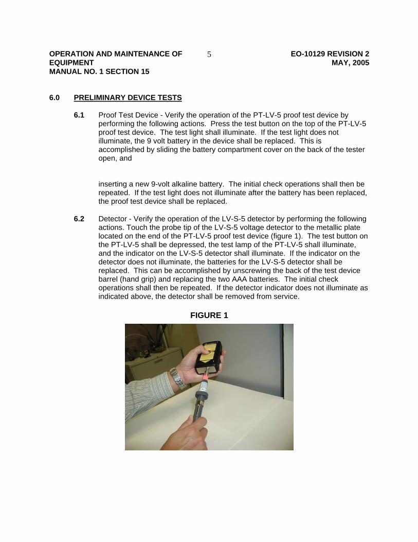
OPERATION AND MAINTENANCE OF EO-10129 REVISION 2 EQUIPMENT MAY, 2005 MANUAL NO. 1 SECTION 15
5
6.0 PRELIMINARY DEVICE TESTS 6.1 Proof Test Device - Verify the operation of the PT-LV-5 proof test device by
performing the following actions. Press the test button on the top of the PT-LV-5 proof test device. The test light shall illuminate. If the test light does not illuminate, the 9 volt battery in the device shall be replaced. This is accomplished by sliding the battery compartment cover on the back of the tester open, and
inserting a new 9-volt alkaline battery. The initial check operations shall then be
repeated. If the test light does not illuminate after the battery has been replaced, the proof test device shall be replaced.
6.2 Detector - Verify the operation of the LV-S-5 detector by performing the following
actions. Touch the probe tip of the LV-S-5 voltage detector to the metallic plate located on the end of the PT-LV-5 proof test device (figure 1). The test button on the PT-LV-5 shall be depressed, the test lamp of the PT-LV-5 shall illuminate, and the indicator on the LV-S-5 detector shall illuminate. If the indicator on the detector does not illuminate, the batteries for the LV-S-5 detector shall be replaced. This can be accomplished by unscrewing the back of the test device barrel (hand grip) and replacing the two AAA batteries. The initial check operations shall then be repeated. If the detector indicator does not illuminate as indicated above, the detector shall be removed from service.
FIGURE 1
OPERATION AND MAINTENANCE OF EO-10129 REVISION 2 EQUIPMENT MAY, 2005 MANUAL NO. 1 SECTION 15
6
7.0 VOLTAGE TEST 7.1 Perform the preliminary tests detailed in paragraph 6.0. 7.2 Clean an area on the surface of the structure to be tested removing all dirt and
rust. Touch the probe tip to the bare metal surface. If stray voltage is present, the probe tip will illuminate.
J.R. Martin J. Schneider Joseph R Martin(signature on file) Joseph R. Martin Manager Environmental Health and Safety Distribution Engineering REVISION 2: Added paragraph 5.2 “detector shall be used without gloves” To be reviewed by 05/10
FILE: Operation and Maintenance of Equipment Manual No. 1, Section 15, Tools

79
This page is intentionally left blank.
. . . . . . .. . .
80
D: B-63 (Stray Voltage Testing Of Company Structures And Streetlights)
June 29, 2005
Bulletin # 63: Secondary System Analysis
Distribution Engineering Department Bulletin
Subject: Stray Voltage Testing of Company Structures and Streetlights (OJT0063) Metal pole streetlights and company structures including, poles, manholes, service boxes, vaults, and Underground Residential Distribution (URD) that contain or support primary or secondary cables or equipment shall be tested for stray voltage before and after working in or on the structure. The paragraphs below describe what should be tested, DC testing, what to do if a stray voltage is found and the required reporting. All AC stray voltage tests shall be conducted in accordance with EO-10129 (Operation And Maintenance Of Low Voltage Detector For Stray Voltage)
WHAT SHOULD BE TESTED? UNDERGROUND STRUCTURES - Test the metallic frame and cover. If the cover has multiple gratings or covers, each piece shall be tested. PADMOUNTS - Test the exterior surface of the Padmounted equipment. SILOS - Test the metallic frame and cover. POLES - Test all metallic surfaces on the pole from grade to a height of seven feet above grade. Surfaces to be tested include ground wires, anchor guys, and riser pipes of any company attached to the pole. Accessible traffic control equipment shall also be tested. Con Ed or other companies, such as Verizon, may own the pole. STREETLIGHTS - Test the metallic frame and cover of metal pole streetlights. Streetlights on wood poles do not need to be tested.
STRUCTURES WITH DC All DC required stray voltage tests shall be conducted as follows:
• All measurements shall be taken on bare metal surfaces.
• Verify the proper operation of the approved DC voltage detector (Fluke model 77/177) by touching the tip of the “live” lead of the device to a known energized voltage source while the tip of the “common” lead is connected to a neutral or ground location. The device shall indicate a voltage reading. Devices that fail to provide a proper voltage reading/indication shall be removed from service.
• Measurements for DC voltage shall be made with portable AC/DC voltmeters. When using these devices, connect to a good neutral or ground with the common (black) AC/DC voltmeter. Measure the voltage between the object (cover, frame, or casting) being tested and a good neutral or ground point. Examples of good ground points are the system neutral, metal water pipes, hydrants, steel faced curbs, street lamp
File: Operation and Maintenance of Equipment, Manual 1 Page 1 of 2 Section 13 Repairs and Miscellaneous Tests
June 29, 2005
neutral or ground. When using curbs as the reference point for measurements, only curbs that have a full steel facing extending from the sidewalk to below the pavement and a minimum continuous length of 10 feet may be utilized. When using these reference points, connect to bare metal surfaces. In locations where the neutral or ground point is longer than the voltmeter lead length, connect to the neutral/ground with an extension lead wire. Secure the other end of the extension lead to the negative (black) probe of the voltmeter. Use care when using extension leads so as to not create a hazard to workers, pedestrian or vehicular traffic.
• The “live” meter probe lead shall then be placed into contact with the cover/frame under inspection.
• If measurements for voltage are being taken with an AC/DC voltmeter the voltage present will be indicated on the meter display. Readings shall be taken on both the AC and DC scales.
WHAT TO DO IF A STRAY VOLTAGE IS FOUND? • When a stray voltage condition is identified with a SV detector, verify the condition
with a voltmeter. If one volt or more (AC or DC) is found, the location will be manned continually and reported to the appropriate Control Center for the creation of an Energized Equipment (ENE) ECS Ticket, unless the crew is investigating an electric shock report. Electric shock reports shall be recorded on ECS tickets with a trouble type of ESR.
• The crew shall make necessary repairs to eliminate the source of the stray voltage.
• Report the identified defects to the local Control Center through the normal ECS procedures (See OJT ECC0100 for reporting the results of stray voltage inspections). The Control Center then updates the ECS to reflect the status of the stray voltage, repair work done to eliminate the stray voltage, and any remaining repair work.
REPORTING The Stray Voltage Log intranet application is the repository for all underground stray voltage tests whether a stray voltage is found or not. Stray voltage tests on poles shall be recorded on the DCAR only when no stray voltage is identified. If a stray voltage is discovered on a pole it shall be immediately reported to the Control Center. L. Scally
Won Choe (Signature on File) Won Choe Department Manager Distribution Engineering Department Secondary System Analysis
File: Operation and Maintenance of Equipment, Manual 1 Page 2 of 2 Section 13 Repairs and Miscellaneous Tests

81
This page is intentionally left blank.
. . . . . . .. . .
82
E: EO-10,358 (Annual Contractor Stray Voltage Inspection Procedure)
CONSOLIDATED EDISON CO. OF NEW YORK INC. 4 IRVING PLACE
NEW YORK, NY 10003
DISTRIBUTION ENGINEERING DEPARTMENT SECONDARY ANALYSIS SECTION
SPECIFICATION EO-10358 REVISION 1
AUGUST 2004
ANNUAL CONTRACTOR STRAY VOLTAGE INSPECTION PROCEDURE
FILE: OPERATION AND MAINTENANCE
OF EQUIPMENT - MANUAL NO. 1 SECTION 13 – REPAIRS AND MISCELLANEOUS TESTS
OPERATION AND - 2 - EO-10358 REVISION 1 MAINTENANCE OF EQUIPMENT AUGUST 2004
Table of Contents
1.0 PURPOSE ................................................................................................................ 3
2.0 APPLICATION.......................................................................................................... 3
3.0 GENERAL ................................................................................................................ 3
4.0 DEFINITIONS........................................................................................................... 3
5.0 STRUCTURES TO BE TESTED .............................................................................. 4
6.0 APPROVED TEST DEVICES................................................................................... 5
7.0 TEST PROCEDURE................................................................................................. 6
8.0 INSPECTION CYCLE............................................................................................... 8
9.0 QUALITY CONTROL................................................................................................ 9
10.0 NOTIFICATION ........................................................................................................ 9
11.0 INFORMATION THAT CON ED WILL PROVIDE TO CONTRACTOR(S) .............. 10
12.0 CONDITIONS OF PROVIDING INFORMATION TO CONTRACTOR(S) ............... 11
13.0 MINIMUM HARDWARE/SOFTWARE REQUIREMENTS....................................... 11
14.0 INFORMATION TO BE RETURNED BY THE CONTRACTOR(S): ........................ 11
15.0 TRAINING .............................................................................................................. 12
16.0 CONTRACTOR INFORMATION ............................................................................ 12
17.0 APPENDIX ............................................................................................................. 14

OPERATION AND - 3 - EO-10358 REVISION 1 MAINTENANCE OF EQUIPMENT AUGUST 2004
1.0 PURPOSE The purpose of this specification is to describe the periodic stray voltage inspections to be performed by a contractor, operation of the required testing devices, the structures required to be tested, notifications of structures found with stray voltage, and data transfer process between the contractor and Con Ed.
2.0 APPLICATION This specification applies to all Operating Regions.
3.0 GENERAL This specification lists the structures by Mains and Service Plates that shall be inspected and the deficiencies that are to be reported when a contractor performs a stray voltage inspection.
4.0 DEFINITIONS 4.1. Alternating Current (AC) - An alternating current (AC) is an electrical
current, where electrical charge oscillates (i.e., moves back and forth), rather than flowing continuously in one direction, as is the case with direct current.
4.2. Direct Current (DC) - Direct current (DC) is the continuous flow of electricity through a conductor such as a wire from high to low potential. In direct current, the electric charges flow always in the same direction, which distinguishes it from alternating current (AC).
4.3. Ground Rod – An electrode placed in the earth and attached to a ground wire.
4.4. Ground Wire – A conductor that is attached to a ground rod, continues vertically up the pole and is attached to an overhead cable or equipment.
4.5. Guy Wire - A galvanized steel wire attached to the pole at an elevation well above the reach of a person at grade to an anchor placed in the ground approximately 12 feet laterally from the pole. (See Figure 1)
4.6. Mains – The low voltage (under 600 volts) AC or DC cables that run between Con Ed structures.
4.7. Mains & Services (M&S) Plate – a map that details the locations and types of manholes, service boxes, mains, services, poles, streetlights, and traffic lights in a geographic area.
4.8. Manhole - An underground structure that contains low voltage (under 600 volts) conductors and primary conductors. This structure can have rectangular or circular covers.
4.9. Poles – A wooden structure owned by Con Ed or Verizon for the purpose of attaching overhead cables and equipment.
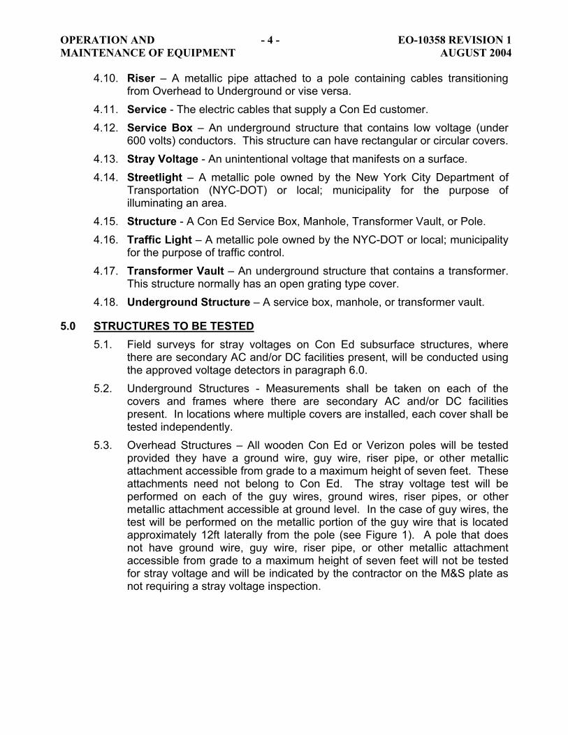
OPERATION AND - 4 - EO-10358 REVISION 1 MAINTENANCE OF EQUIPMENT AUGUST 2004
4.10. Riser – A metallic pipe attached to a pole containing cables transitioning from Overhead to Underground or vise versa.
4.11. Service - The electric cables that supply a Con Ed customer. 4.12. Service Box – An underground structure that contains low voltage (under
600 volts) conductors. This structure can have rectangular or circular covers. 4.13. Stray Voltage - An unintentional voltage that manifests on a surface. 4.14. Streetlight – A metallic pole owned by the New York City Department of
Transportation (NYC-DOT) or local; municipality for the purpose of illuminating an area.
4.15. Structure - A Con Ed Service Box, Manhole, Transformer Vault, or Pole. 4.16. Traffic Light – A metallic pole owned by the NYC-DOT or local; municipality
for the purpose of traffic control. 4.17. Transformer Vault – An underground structure that contains a transformer.
This structure normally has an open grating type cover. 4.18. Underground Structure – A service box, manhole, or transformer vault.
5.0 STRUCTURES TO BE TESTED 5.1. Field surveys for stray voltages on Con Ed subsurface structures, where
there are secondary AC and/or DC facilities present, will be conducted using the approved voltage detectors in paragraph 6.0.
5.2. Underground Structures - Measurements shall be taken on each of the covers and frames where there are secondary AC and/or DC facilities present. In locations where multiple covers are installed, each cover shall be tested independently.
5.3. Overhead Structures – All wooden Con Ed or Verizon poles will be tested provided they have a ground wire, guy wire, riser pipe, or other metallic attachment accessible from grade to a maximum height of seven feet. These attachments need not belong to Con Ed. The stray voltage test will be performed on each of the guy wires, ground wires, riser pipes, or other metallic attachment accessible at ground level. In the case of guy wires, the test will be performed on the metallic portion of the guy wire that is located approximately 12ft laterally from the pole (see Figure 1). A pole that does not have ground wire, guy wire, riser pipe, or other metallic attachment accessible from grade to a maximum height of seven feet will not be tested for stray voltage and will be indicated by the contractor on the M&S plate as not requiring a stray voltage inspection.

OPERATION AND - 5 - EO-10358 REVISION 1 MAINTENANCE OF EQUIPMENT AUGUST 2004
Figure 1
5.4. Streetlights - All metal pole streetlights mapped on the M&S plates to be tested will be tested for stray voltage no earlier than 1-hour after sundown and cease no later than 1-hour before sunrise. Sunrise and sunset times for the town/region to be tested shall be obtained from the U.S. Naval Observatory – Astronomical Applications Department, available through the following link.
http://aa.usno.navy.mil/data/docs/RS_OneDay.html5.5. Traffic Lights, Etc. - All metal pole streetlights mapped on the M&S plates to
be tested will be tested for stray voltage no earlier than 1-hour after sundown and cease no later than 1-hour before sunrise. Sunrise and sunset times for the town/region to be tested shall be obtained from the U.S. Naval Observatory – Astronomical Applications Department, available through the following link in the preceding paragraph. The stray voltage test will be performed for the entire cycle of the streetlight i.e. green, yellow, red, walk/don’t walk.
5.6. Structures that are normally buried are not required to be tested.
6.0 APPROVED TEST DEVICES 6.1. The following devices are approved for AC stray voltage inspections and
shall be obtained by the contractor: 6.1.1. HD Tester LV-S-5 6.1.2. Greenlee Model 2010 Voltage Detector (Class & Stock # 578-1273).
This device is approved as an interim measure until the HD LV-S-5 is available. When the HD LV-S-5 becomes available all testing will be conducted with the HD LV-S-5.
6.2. DC Testing 6.2.1. Fluke 77 6.2.2. Fluke 177
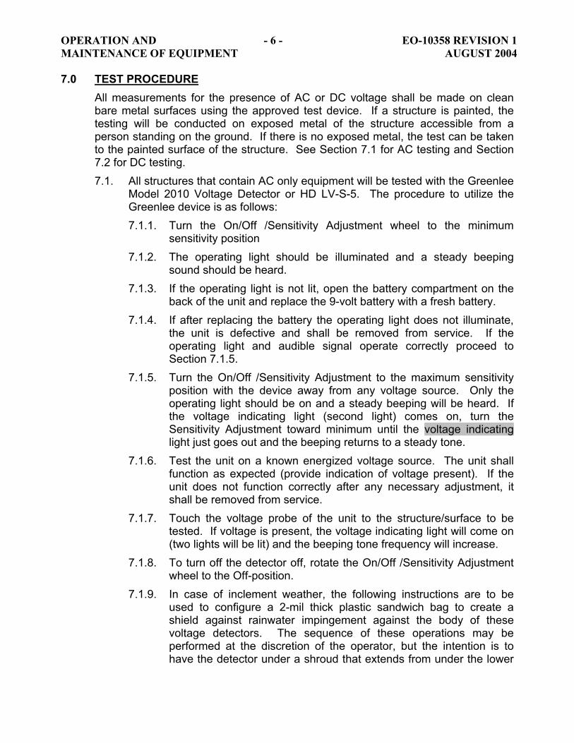
OPERATION AND - 6 - EO-10358 REVISION 1 MAINTENANCE OF EQUIPMENT AUGUST 2004 7.0 TEST PROCEDURE
All measurements for the presence of AC or DC voltage shall be made on clean bare metal surfaces using the approved test device. If a structure is painted, the testing will be conducted on exposed metal of the structure accessible from a person standing on the ground. If there is no exposed metal, the test can be taken to the painted surface of the structure. See Section 7.1 for AC testing and Section 7.2 for DC testing. 7.1. All structures that contain AC only equipment will be tested with the Greenlee
Model 2010 Voltage Detector or HD LV-S-5. The procedure to utilize the Greenlee device is as follows: 7.1.1. Turn the On/Off /Sensitivity Adjustment wheel to the minimum
sensitivity position 7.1.2. The operating light should be illuminated and a steady beeping
sound should be heard. 7.1.3. If the operating light is not lit, open the battery compartment on the
back of the unit and replace the 9-volt battery with a fresh battery. 7.1.4. If after replacing the battery the operating light does not illuminate,
the unit is defective and shall be removed from service. If the operating light and audible signal operate correctly proceed to Section 7.1.5.
7.1.5. Turn the On/Off /Sensitivity Adjustment to the maximum sensitivity position with the device away from any voltage source. Only the operating light should be on and a steady beeping will be heard. If the voltage indicating light (second light) comes on, turn the Sensitivity Adjustment toward minimum until the voltage indicating light just goes out and the beeping returns to a steady tone.
7.1.6. Test the unit on a known energized voltage source. The unit shall function as expected (provide indication of voltage present). If the unit does not function correctly after any necessary adjustment, it shall be removed from service.
7.1.7. Touch the voltage probe of the unit to the structure/surface to be tested. If voltage is present, the voltage indicating light will come on (two lights will be lit) and the beeping tone frequency will increase.
7.1.8. To turn off the detector off, rotate the On/Off /Sensitivity Adjustment wheel to the Off-position.
7.1.9. In case of inclement weather, the following instructions are to be used to configure a 2-mil thick plastic sandwich bag to create a shield against rainwater impingement against the body of these voltage detectors. The sequence of these operations may be performed at the discretion of the operator, but the intention is to have the detector under a shroud that extends from under the lower
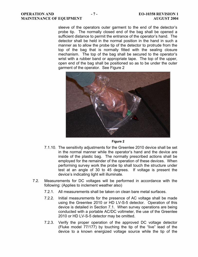
OPERATION AND - 7 - EO-10358 REVISION 1 MAINTENANCE OF EQUIPMENT AUGUST 2004
sleeve of the operators outer garment to the end of the detector’s probe tip. The normally closed end of the bag shall be opened a sufficient distance to permit the entrance of the operator’s hand. The detector shall be held in the normal position in the hand in such a manner as to allow the probe tip of the detector to protrude from the top of the bag that is normally fitted with the sealing closure mechanism. The top of the bag shall be secured to the operator’s wrist with a rubber band or appropriate tape. The top of the upper, open end of the bag shall be positioned so as to be under the outer garment of the operator. See Figure 2
Figure 2
7.1.10. The sensitivity adjustments for the Greenlee 2010 device shall be set in the normal manner while the operator’s hand and the device are inside of the plastic bag. The normally prescribed actions shall be employed for the remainder of the operation of these devices. When performing survey work the probe tip shall touch the structure under test at an angle of 30 to 45 degrees. If voltage is present the device’s indicating light will illuminate.
7.2. Measurements for DC voltages will be performed in accordance with the following: (Applies to inclement weather also) 7.2.1. All measurements shall be taken on clean bare metal surfaces. 7.2.2. Initial measurements for the presence of AC voltage shall be made
using the Greenlee 2010 or HD LV-S-5 detector. Operation of this device is detailed in Section 7.1. When survey operations are being conducted with a portable AC/DC voltmeter, the use of the Greenlee 2010 or HD LV-S-5 detector may be omitted.
7.2.3. Verify the proper operation of the approved DC voltage detector (Fluke model 77/177) by touching the tip of the “live” lead of the device to a known energized voltage source while the tip of the
OPERATION AND - 8 - EO-10358 REVISION 1 MAINTENANCE OF EQUIPMENT AUGUST 2004
“common” lead is connected to a neutral or ground location. The device shall indicate a voltage reading. Devices that fail to provide a proper voltage reading/indication shall be removed from service.
7.2.4. Measurements for DC voltage shall be made with portable AC/DC voltmeters. When using these devices, connection shall be made to suitable neutral or ground source with the common (black) AC/DC voltmeter or voltage continuity tester lead. Measurements for voltage shall be taken between the object (cover, frame, or casting) being surveyed and a suitable neutral or ground point (i.e., system neutral, metal water pipe, hydrant, steel faced curb, street lamp neutral or ground). When using roadway curbs as the reference point for measurements, only curbs that have a full steel facing extending from the sidewalk to below the pavement and a minimum continuous length of 10 feet may be utilized. When using these reference points, connections shall be made to clean bare metal surfaces. In locations where the neutral or ground point is at a distance in excess of the voltmeter lead length, the connection to the neutral/ground shall be made with suitable gauge/length lead wire, the other end of which shall be securely connected to the negative (black) probe of the meter or voltage continuity tester. When using such “extension leads” appropriate care shall be taken in the placement of such leads so as to not create a hazard to workers, pedestrian or vehicular traffic.
7.2.5. The “live” meter probe lead shall then be placed into contact with the cover/frame under inspection. Typical covers and frames are shown in Appendix A.
7.2.6. If measurements for voltage are being taken with an AC/DC voltmeter the voltage present will be indicated on the meter display. Readings shall be taken on both the AC and DC scales.
8.0 INSPECTION CYCLE 8.1. The inspection program is divided into two segments – Initial inspection and
Periodic cycle. Both programs encompass the same structures to be tested. 8.2. The Initial inspection will be complete by year-end 2004. 8.3. The Periodic Cycle encompasses a flat 12-month program in which the
structures will be tested. 8.3.1. The contractor is responsible to initiate a testing program such that
the completed year-to-date inspections do not vary more than ±10% from a 12-month average of the structures to be tested.
8.3.2. The contractor will ensure that all structures are completed by year-end and all required data is forwarded to Con Ed by second Monday of the following year.
OPERATION AND - 9 - EO-10358 REVISION 1 MAINTENANCE OF EQUIPMENT AUGUST 2004
8.4. In the event that the contractor has made a reasonable effort and cannot locate a structure, the contractor will inform Construction Management. Construction Management will verify the existence and location of the structure with Regional Engineering. 8.4.1. If Regional Engineering indicates that the structure still exists, then
Construction Management and the contractor will schedule a meet at the location to verify that the structure cannot be located. Construction may require the use of excavation crews or contractors to aid in locating the structure. If Construction Management determines that the contractor has not made a reasonable effort to locate the structure, then Construction Management will initiate an Action-line Complaint on the contractor.
8.4.2. If Regional Engineering indicates that the structure no longer exists then the structure will be removed from the mapping and property record systems.
8.5. In the event that the contractor has located unmapped Con Ed structures, the contractor will mark the M&S plate to indicate the location and result of voltage testing. The contractor will inform Construction Management of the discovery of an unmapped structure. Construction Management will verify the existence and location of the structure with Regional Engineering. Regional Engineering will ensure that the structure is added to the appropriate mapping and property records systems.
9.0 QUALITY CONTROL Construction Management will perform periodic quality control inspections. Streetlight quality control inspections will be performed at night when the streetlights are illuminated.
10.0 NOTIFICATION When testing indicates the presence of voltage on a structure, the field crew or supervisor will call the Customer Service Area (CSA) control room and report the following information:
CSA (e.g. - Brooklyn, Queens, Staten Island, Bronx, Westchester, or Manhattan)
Structure Number: (e.g.- Manhole #12345) Location: (e.g. 409 East 90th Street, Manhattan) Nearest Cross Street York Ave. M&S Plate Number: (e.g.- 41-L) Name: (e.g.- John Doe)
10.1. If any voltage is detected, measures shall be taken by the contractor to restrict access by the public to any facilities found to have voltage potential
OPERATION AND - 10 - EO-10358 REVISION 1 MAINTENANCE OF EQUIPMENT AUGUST 2004
present, such as barricade tape or barricades. If the structure is in a traffic lane, the structure shall be watched from the curbside.
10.2. The survey crews will stand-by the structure until relieved by a Con Ed employee.
11.0 INFORMATION THAT CON ED WILL PROVIDE TO CONTRACTOR(S) The following information will be provided to contractors to facilitate annual stray voltage testing: 11.1. Intranet access to M&S plates
Con Ed will provide access to M&S plates through a secured Virtual Private Network (VPN) connection to the Con Ed Intranet. Once on the Intranet site, the contractor(s) will have access to the most up-to-date copies of Con Ed maps. Contractor staff will be able to produce printed or plotted copies on hardware described below, using functions available on the Intranet site. Use of VPN and other necessary training will be provided as necessary.
11.2. Intranet access to Excel spreadsheets that identify the structures and equipment for testing. Microsoft Excel 2000 spreadsheets will be provided electronically to identify structures and equipment for testing. These spreadsheets will be provided in the following format: 11.2.1. Underground Structures
\\m020diseng1\DATADIRS\Secondary Analysis\Stray Voltage Spec\Structures for Stray Voltage Inspections\Underground StructuresThere is a folder for each region. Some folders have multiple files. Each file must be inspected. Manhattan has an additional file for the DC structures. Each file contains the structure type and structure number to be tested.
11.2.2. Overhead Structures \\m020diseng1\DATADIRS\Secondary Analysis\Stray Voltage Spec\Structures for Stray Voltage Inspections\PolesThere is a folder for each region. Some folders have multiple files. Each file must be inspected. Each file contains the structure type, structure number, and address of the pole. The structure will be tested in accordance with paragraph 5.3.
11.2.3. Street and Traffic Lights \\m020diseng1\DATADIRS\Secondary Analysis\Stray Voltage Spec\Structures for Stray Voltage Inspections\Street and Traffic LightsFor each M&S plate to be tested, Con Ed will supply the number of streetlight and traffic lights for which Con Ed supplies electric service. These same street and traffic lights are mapped on the M&S plates.
OPERATION AND - 11 - EO-10358 REVISION 1 MAINTENANCE OF EQUIPMENT AUGUST 2004 12.0 CONDITIONS OF PROVIDING INFORMATION TO CONTRACTOR(S)
12.1. Contractor shall sign and be in compliance with Con Ed’s non-disclosure/confidentiality agreements regarding facility maps, plates, drawings, etc. used for the purpose of satisfying its contractual obligations in advance of award of a contract.
12.2. Con Ed requires the contractor(s) to carefully manage the distribution and disposition of printed and plotted maps due to the sensitive nature of the information they contain. Contractor(s) shall maintain a daily record of the employees to whom they are distributed and shall ensure that all copies are destroyed by the end of each workday. Contractor(s) will include with their proposals a written procedure for implementing these requirements.
13.0 MINIMUM HARDWARE/SOFTWARE REQUIREMENTS 13.1. PC’s with the following minimum configuration and software: 13.2. Windows 2000 Business Edition 13.3. Office XP Professional 13.4. CGM Viewer, provided by Con Ed at no additional cost to the contractor 13.5. Firewall software to be provided by the contractor at its cost. Black Ice
Software is recommended. 13.6. Recommended: Dell GX Business Class Desktop PC or equivalent 13.7. Plotter to print M&S plates. Recommended: Xerox 510 Copy System. 13.8. Broadband Internet connection (DSL, Cable, or T1) 13.9. Contractor is responsible for hiring staff to administer the hardware and
software installation, operation and maintenance.
14.0 INFORMATION TO BE RETURNED BY THE CONTRACTOR(S): 14.1. Inspection information in a comma delimited file. Sample files attached:
\\m020diseng1\DATADIRS\Secondary Analysis\Stray Voltage Spec\Structures for Stray Voltage Inspections\Sample Return Data
14.2. Initially files will be transmitted via an ftp site daily (for checking purposes), then switch to monthly.
14.3. The results of each inspection shall be recorded in an electronic file and sent Con Ed on a weekly basis.
14.4. If there is no voltage at the structure tested, a “P” and the date tested shall be marked on the M&S Plate to indicate that the structure has passed Annual Testing.
14.5. When the proximity detector or portable AC/DC voltmeter indicates the presence of voltage at any location, the structure number and all other
OPERATION AND - 12 - EO-10358 REVISION 1 MAINTENANCE OF EQUIPMENT AUGUST 2004
relevant details (See Section 10) will be called into the appropriate CSA control room to arrange for the repair.
14.6. Each structure will be marked with a paint dot to indicate it was tested. Structures tested on rainy or snowy days are exempt from paint dot indication. See the list below for the appropriate color: 14.6.1. 2004 Yellow (Aervoe 282) 14.6.2. 2005 Orange (Aervoe 288) 14.6.3. 2006 Red (Aervoe 281) 14.6.4. 2007 Blue (Aervoe 209) 14.6.5. 2008 Start cycle over again with Yellow
14.7. The contractor will present the completed hard copy M&S plates to Con Ed on a monthly basis.
15.0 TRAINING At a minimum, the contractor personnel conducting these tests should have knowledge and training in the following topics: 15.1. Use of Proper Personal Protective Equipment 15.2. Work Area Protection 15.3. Hazard Communication 15.4. First Aid CPR (This is required only on multi-person crews.) 15.5. The proper use of the Approved Voltage Detector and Meter 15.6. Contractors shall not enter subsurface structures. 15.7. Content and Implementation of Contractor eHASP.
16.0 CONTRACTOR INFORMATION The following information, at a minimum, needs to be communicated to all personnel, at the beginning of each shift, for Stray Voltage Detection Work. 16.1. No cover or frame is to be touched with a bare hand or any part of the body;
only the voltage detector or meter is to be used to make contact with the facilities.
16.2. Each individual needs to be aware of his/her surroundings at all times. 16.3. Always make sure to observe all traffic before entering a street, either at
intersections or any other point. A flag person should be used to control the traffic flow when needed.
16.4. Always wear a traffic safety vest (DOT Compliant Class II). 16.5. Be aware that when bending down, the visibility benefits of the traffic safety
vest are diminished.
OPERATION AND - 13 - EO-10358 REVISION 1 MAINTENANCE OF EQUIPMENT AUGUST 2004
16.6. Always obey all traffic control devices. 16.7. When finding a facility that has voltage detected that is in traffic, do not stand
in traffic, but watch the facility until the appropriate Con Ed crew arrives. 16.8. If at all possible, stand facing oncoming traffic when in the street.
Won Choe (Signature on File) Won Choe Department Manager Secondary Systems Analysis Distribution Engineering Dept.
Leo A. Scally
REVISION 1 Corrected typo in paragraph 7.1.5
FILE Operation and Maintenance of Equipment - Manual No. 1 Section 13 – Repairs and Miscellaneous Tests
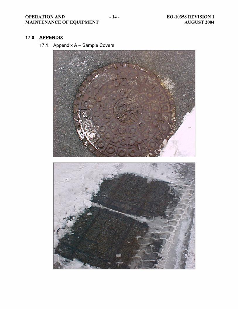
OPERATION AND - 14 - EO-10358 REVISION 1 MAINTENANCE OF EQUIPMENT AUGUST 2004
17.0 APPENDIX 17.1. Appendix A – Sample Covers
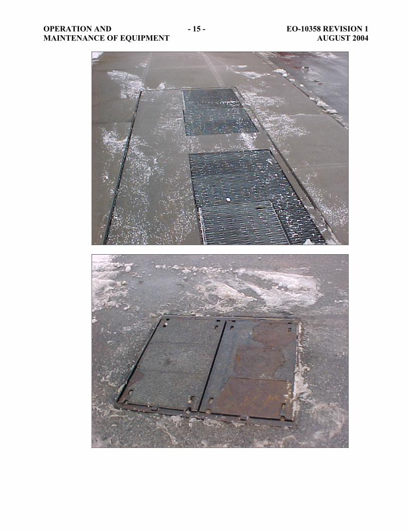
OPERATION AND - 15 - EO-10358 REVISION 1 MAINTENANCE OF EQUIPMENT AUGUST 2004

OPERATION AND - 16 - EO-10358 REVISION 1 MAINTENANCE OF EQUIPMENT AUGUST 2004

83
This page is intentionally left blank.
. . . . . . .. . .
84
F: EO-10,360 (Troubleshooting Of Streetlights)
CONSOLIDATED EDISON COMPANY OF NEW YORK, INC. 4 IRVING PLACE
NEW YORK, NEW YORK 10003
DISTRIBUTION ENGINEERING DEPARTMENT SECONDARY SYSTEM ANALYSIS
SPECIFICATION EO-10360 REVISION 1
OCTOBER 2005
TROUBLESHOOTING OF STREETLIGHTS
FILE: ENGINEERING MANUAL NO. 1, SECTION13 FIELD MANUAL NO. 1, SECTION 11
FIELD MANUAL NO. 3, SECTION 1 FIELD MANUAL NO. 9, SECTION 15 FIELD MANUAL NO.23, SECTION 6.1 TARGET AUDIENCE ELECTRIC OPERATIONS NESC REFERENCE 011. ITEM C
Construction Standards 2 EO-10360 Revision 1 Manual No. 3, Section 8 October 2005 TABLE OF CONTENTS 1.0 Purpose ................................................................................................................ 3
2.0 Application............................................................................................................ 3
3.0 Troubleshooting Streetlights – No Light Or Stray Voltage .................................... 3
4.0 Streetlight Cover................................................................................................... 5
5.0 Reference Specifications...................................................................................... 5
6.0 Appendix A: Flowchart For Troubleshooting Of Streetlights with Stray Voltage. .. 7
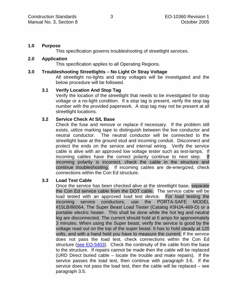
Construction Standards 3 EO-10360 Revision 1 Manual No. 3, Section 8 October 2005 1.0 Purpose
This specification governs troubleshooting of streetlight services. 2.0 Application
This specification applies to all Operating Regions. 3.0 Troubleshooting Streetlights – No Light Or Stray Voltage
All streetlight no-lights and stray voltages will be investigated and the below procedure will be followed.
3.1 Verify Location And Stop Tag Verify the location of the streetlight that needs to be investigated for stray voltage or a no-light condition. If a stop tag is present, verify the stop tag number with the provided paperwork. A stop tag may not be present at all streetlight locations.
3.2 Service Check At S/L Base Check the fuse and remove or replace if necessary. If the problem still exists, utilize marking tape to distinguish between the live conductor and neutral conductor. The neutral conductor will be connected to the streetlight base at the ground stud and incoming conduit. Disconnect and protect the ends on the service and internal wiring. Verify the service cable is alive with an approved low voltage tester such as test-lamps. If incoming cables have the correct polarity continue to next step. If incoming polarity is incorrect, check the cable in the structure and continue troubleshooting. If incoming cables are de-energized, check connections within the Con Ed structure.
3.3 Load Test Cable Once the service has been checked alive at the streetlight base, separate the Con Ed service cable from the DOT cable. The service cable will be load tested with an approved load test device. For load testing the incoming service conductors, use the PORTA-SAFE MODEL #15LB/86064, The Super Beast Load Tester (Catalog #3HJA-469-D) or a portable electric heater. This shall be done while the hot leg and neutral leg are disconnected. The current should hold at 6 amps for approximately 3 minutes. When using the Super beast, verify the service is good by the voltage read out on the top of the super beast. It has to hold steady at 120 volts, and with a hand held you have to measure the current. If the service does not pass the load test, check connections within the Con Ed structure (see EO-5403). Check the continuity of the cable from the base to the structure. If repairs cannot be made then the cable will be replaced (URD Direct buried cable – locate the trouble and make repairs). If the service passes the load test, then continue with paragraph 3.6. If the service does not pass the load test, then the cable will be replaced – see paragraph 3.5.
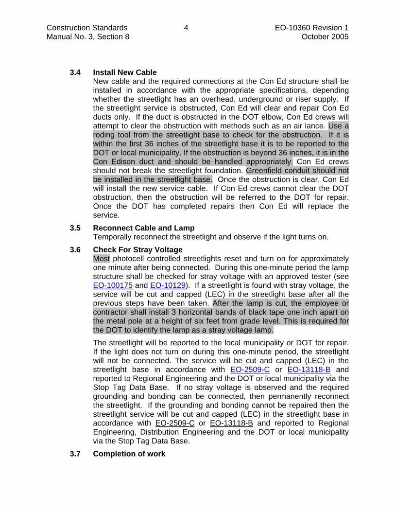
Construction Standards 4 EO-10360 Revision 1 Manual No. 3, Section 8 October 2005
3.4 Install New Cable New cable and the required connections at the Con Ed structure shall be installed in accordance with the appropriate specifications, depending whether the streetlight has an overhead, underground or riser supply. If the streetlight service is obstructed, Con Ed will clear and repair Con Ed ducts only. If the duct is obstructed in the DOT elbow, Con Ed crews will attempt to clear the obstruction with methods such as an air lance. Use a roding tool from the streetlight base to check for the obstruction. If it is within the first 36 inches of the streetlight base it is to be reported to the DOT or local municipality. If the obstruction is beyond 36 inches, it is in the Con Edison duct and should be handled appropriately. Con Ed crews should not break the streetlight foundation. Greenfield conduit should not be installed in the streetlight base. Once the obstruction is clear, Con Ed will install the new service cable. If Con Ed crews cannot clear the DOT obstruction, then the obstruction will be referred to the DOT for repair. Once the DOT has completed repairs then Con Ed will replace the service.
3.5 Reconnect Cable and Lamp Temporally reconnect the streetlight and observe if the light turns on.
3.6 Check For Stray Voltage Most photocell controlled streetlights reset and turn on for approximately one minute after being connected. During this one-minute period the lamp structure shall be checked for stray voltage with an approved tester (see EO-100175 and EO-10129). If a streetlight is found with stray voltage, the service will be cut and capped (LEC) in the streetlight base after all the previous steps have been taken. After the lamp is cut, the employee or contractor shall install 3 horizontal bands of black tape one inch apart on the metal pole at a height of six feet from grade level. This is required for the DOT to identify the lamp as a stray voltage lamp. The streetlight will be reported to the local municipality or DOT for repair. If the light does not turn on during this one-minute period, the streetlight will not be connected. The service will be cut and capped (LEC) in the streetlight base in accordance with EO-2509-C or EO-13118-B and reported to Regional Engineering and the DOT or local municipality via the Stop Tag Data Base. If no stray voltage is observed and the required grounding and bonding can be connected, then permanently reconnect the streetlight. If the grounding and bonding cannot be repaired then the streetlight service will be cut and capped (LEC) in the streetlight base in accordance with EO-2509-C or EO-13118-B and reported to Regional Engineering, Distribution Engineering and the DOT or local municipality via the Stop Tag Data Base.
3.7 Completion of work
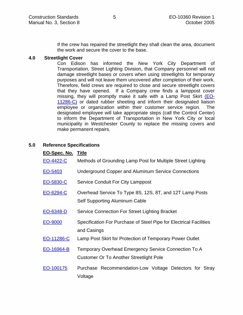
Construction Standards 5 EO-10360 Revision 1 Manual No. 3, Section 8 October 2005
If the crew has repaired the streetlight they shall clean the area, document the work and secure the cover to the base.
4.0 Streetlight Cover Con Edison has informed the New York City Department of Transportation, Street Lighting Division, that Company personnel will not damage streetlight bases or covers when using streetlights for temporary purposes and will not leave them uncovered after completion of their work. Therefore, field crews are required to close and secure streetlight covers that they have opened. If a Company crew finds a lamppost cover missing, they will promptly make it safe with a Lamp Post Skirt (EO-11286-C) or dated rubber sheeting and inform their designated liaison employee or organization within their customer service region. The designated employee will take appropriate steps (call the Control Center) to inform the Department of Transportation in New York City or local municipality in Westchester County to replace the missing covers and make permanent repairs.
5.0 Reference Specifications
EO-Spec. No. Title EO-4422-C Methods of Grounding Lamp Post for Multiple Street Lighting
EO-5403 Underground Copper and Aluminum Service Connections
EO-5830-C Service Conduit For City Lamppost
EO-6294-C Overhead Service To Type 8S, 12S, 8T, and 12T Lamp Posts
Self Supporting Aluminum Cable
EO-6348-D Service Connection For Street Lighting Bracket
EO-9000 Specification For Purchase of Steel Pipe for Electrical Facilities
and Casings
EO-11286-C Lamp Post Skirt for Protection of Temporary Power Outlet
EO-16964-B Temporary Overhead Emergency Service Connection To A
Customer Or To Another Streetlight Pole
EO-100175 Purchase Recommendation-Low Voltage Detectors for Stray
Voltage
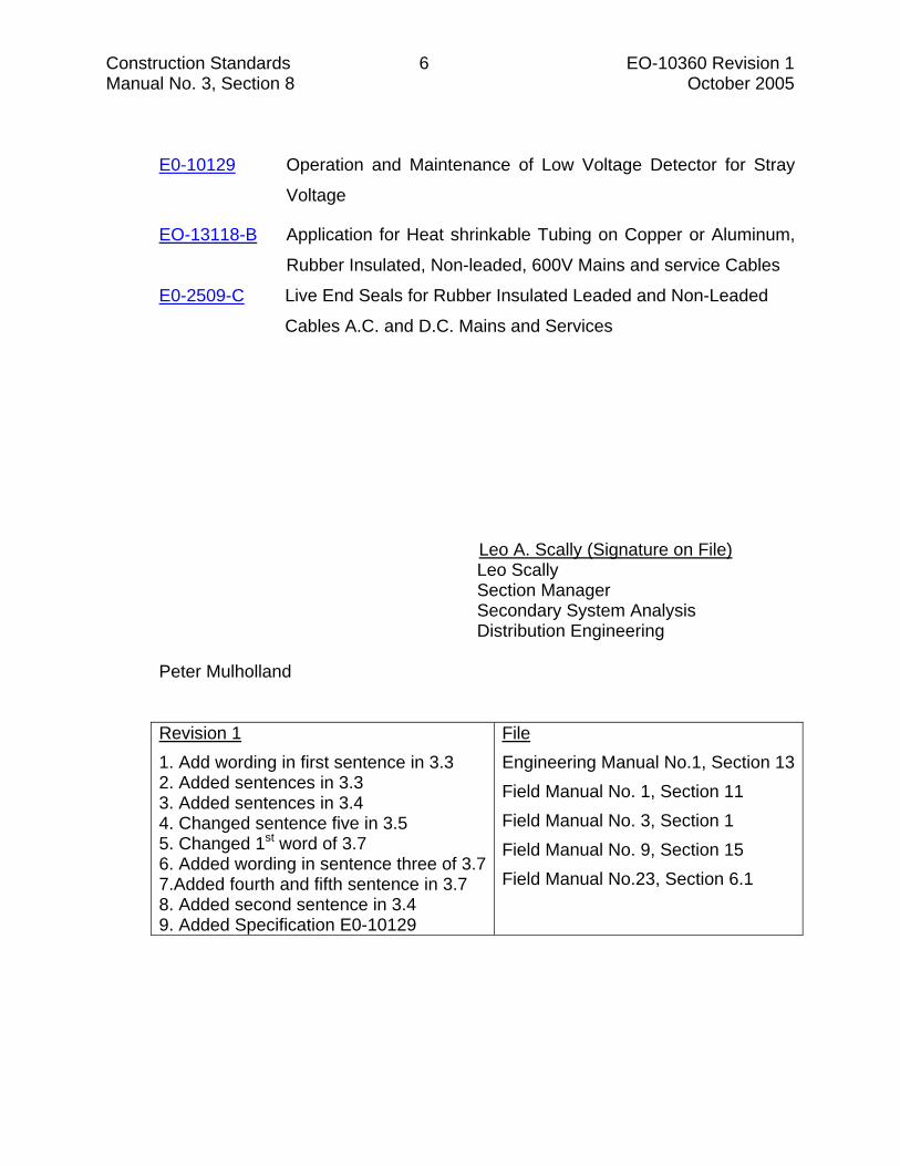
Construction Standards 6 EO-10360 Revision 1 Manual No. 3, Section 8 October 2005
E0-10129 Operation and Maintenance of Low Voltage Detector for Stray
Voltage
EO-13118-B Application for Heat shrinkable Tubing on Copper or Aluminum,
Rubber Insulated, Non-leaded, 600V Mains and service Cables
E0-2509-C Live End Seals for Rubber Insulated Leaded and Non-Leaded
Cables A.C. and D.C. Mains and Services
Leo A. Scally (Signature on File)
Leo Scally Section Manager Secondary System Analysis Distribution Engineering
Peter Mulholland
Revision 11. Add wording in first sentence in 3.3 2. Added sentences in 3.3 3. Added sentences in 3.4 4. Changed sentence five in 3.5 5. Changed 1st word of 3.7 6. Added wording in sentence three of 3.7 7.Added fourth and fifth sentence in 3.7 8. Added second sentence in 3.4 9. Added Specification E0-10129
File Engineering Manual No.1, Section 13Field Manual No. 1, Section 11 Field Manual No. 3, Section 1 Field Manual No. 9, Section 15 Field Manual No.23, Section 6.1

Construction Standards 7 EO-10360 Revision 1 Manual No. 3, Section 8 October 2005 6.0 Appendix A: Flowchart For Troubleshooting Of Streetlights with Stray
Voltage.
TROUBLESHOOTING STREETLIGHTS
S/L ON?REMOVE/REINSTALL FUSE
S/L COMES ON?
NO
STRAY VOLTAGE?
YES
CLOSE OUT B-TICKET
NO
SEPARATE CON ED SERVICE
COMPLETELY FROM DOT
CABLE AND CHECK POLARITY
YES
SVCCABLE PASS
LOADTEST
CUT/CAP SERVICE IN S/L
BASE
YES
CENTRAL STREETLIGHT GROUP WILL
NOTIFY DOT TO MAKE REPAIRS
CONTINUE TROUBLESHOOTING
SERVICE TO DETERMINE CAUSE
NO
UPDATE B-TICKET & CLOSE
OUT
UPDATE B-TICKET
CENTRAL STREETLIGHT GROUP WILL
NOTIFY DOT OF REPAIRS
COMPLETED OR REPAIRS IN PROGRESS
NO
STRAY VOLTAGE?YES
CLOSE OUT B-TICKET
NO
YES

85
G: Shunt Resistor Brochure

SHUNT RESISTOR DESIGN 1. The shunt resistor shall consist of five
100Ω resistors wired in series.
2. Each resistor shall be a minimum of 10 watts (Radio Shack Part #271-135)
3. The case shall be a 4 AA battery holder (Radio Shack Part #270-409)
4. The leads shall be banana leads (Radio Shack Part #278-713)
5. All connections shall be soldered, taped securely and confined within the shunt resistor housing.
RED
BLACK
FLUKE DIGITAL VOLTMETER
DUMMY LOAD
TEST PROBES
Questions? Call
917 – 417 - 8282
Con Edison Leo A. Scally
Section Manager Secondary System Analysis 4 Irving Place – Room 1138
New York, NY 10003 Phone (212) 460-6462
Cell (917) 417-8282 Email [email protected]
http://www.coned.com/
CON EDISON
UTILIZING SHUNT RESISTORS TO PREVENT FALSE STRAY VOLTAGE DETECTIONS ON THE OVERHEAD SYSTEM
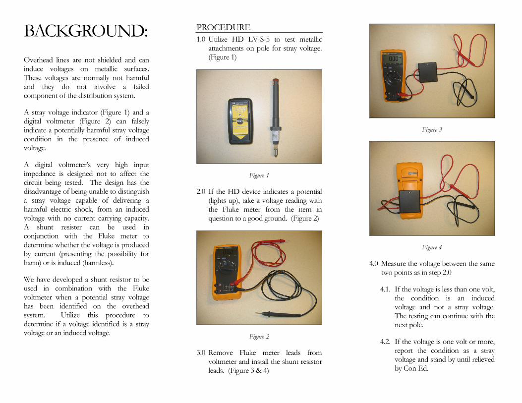
BACKGROUND: Overhead lines are not shielded and can induce voltages on metallic surfaces. These voltages are normally not harmful and they do not involve a failed component of the distribution system.
A stray voltage indicator (Figure 1) and a digital voltmeter (Figure 2) can falsely indicate a potentially harmful stray voltage condition in the presence of induced voltage.
A digital voltmeter’s very high input impedance is designed not to affect the circuit being tested. The design has the disadvantage of being unable to distinguish a stray voltage capable of delivering a harmful electric shock, from an induced voltage with no current carrying capacity. A shunt resister can be used in conjunction with the Fluke meter to determine whether the voltage is produced by current (presenting the possibility for harm) or is induced (harmless).
We have developed a shunt resistor to be used in combination with the Fluke voltmeter when a potential stray voltage has been identified on the overhead system. Utilize this procedure to determine if a voltage identified is a stray voltage or an induced voltage.
PROCEDURE 1.0 Utilize HD LV-S-5 to test metallic
attachments on pole for stray voltage. (Figure 1)
Figure 1
2.0 If the HD device indicates a potential (lights up), take a voltage reading with the Fluke meter from the item in question to a good ground. (Figure 2)
Figure 2
3.0 Remove Fluke meter leads from voltmeter and install the shunt resistor leads. (Figure 3 & 4)
Figure 3
Figure 4
4.0 Measure the voltage between the same two points as in step 2.0
4.1. If the voltage is less than one volt, the condition is an induced voltage and not a stray voltage. The testing can continue with the next pole.
4.2. If the voltage is one volt or more, report the condition as a stray voltage and stand by until relieved by Con Ed.

. . . . . . .. . .
86
This page is intentionally left blank.

87
H: Overhead Transmission Stray Voltage Testing Specification
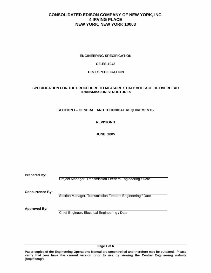
CONSOLIDATED EDISON COMPANY OF NEW YORK, INC. 4 IRVING PLACE
NEW YORK, NEW YORK 10003
Page 1 of 6
ENGINEERING SPECIFICATION
CE-ES-1043
TEST SPECIFICATION
SPECIFICATION FOR THE PROCEDURE TO MEASURE STRAY VOLTAGE OF OVERHEAD TRANSMISSION STRUCTURES
SECTION I – GENERAL AND TECHNICAL REQUIREMENTS
REVISION 1
JUNE, 2005
Prepared By:
Project Manager, Transmission Feeders Engineering / Date
Paper copies of the Engineering Operations Manual are uncontrolled and therefore may be outdated. Please verify that you have the current version prior to use by viewing the Central Engineering website (http://ceng/).
Concurrence By: Section Manager, Transmission Feeders Engineering / Date
Approved By: Chief Engineer, Electrical Engineering / Date
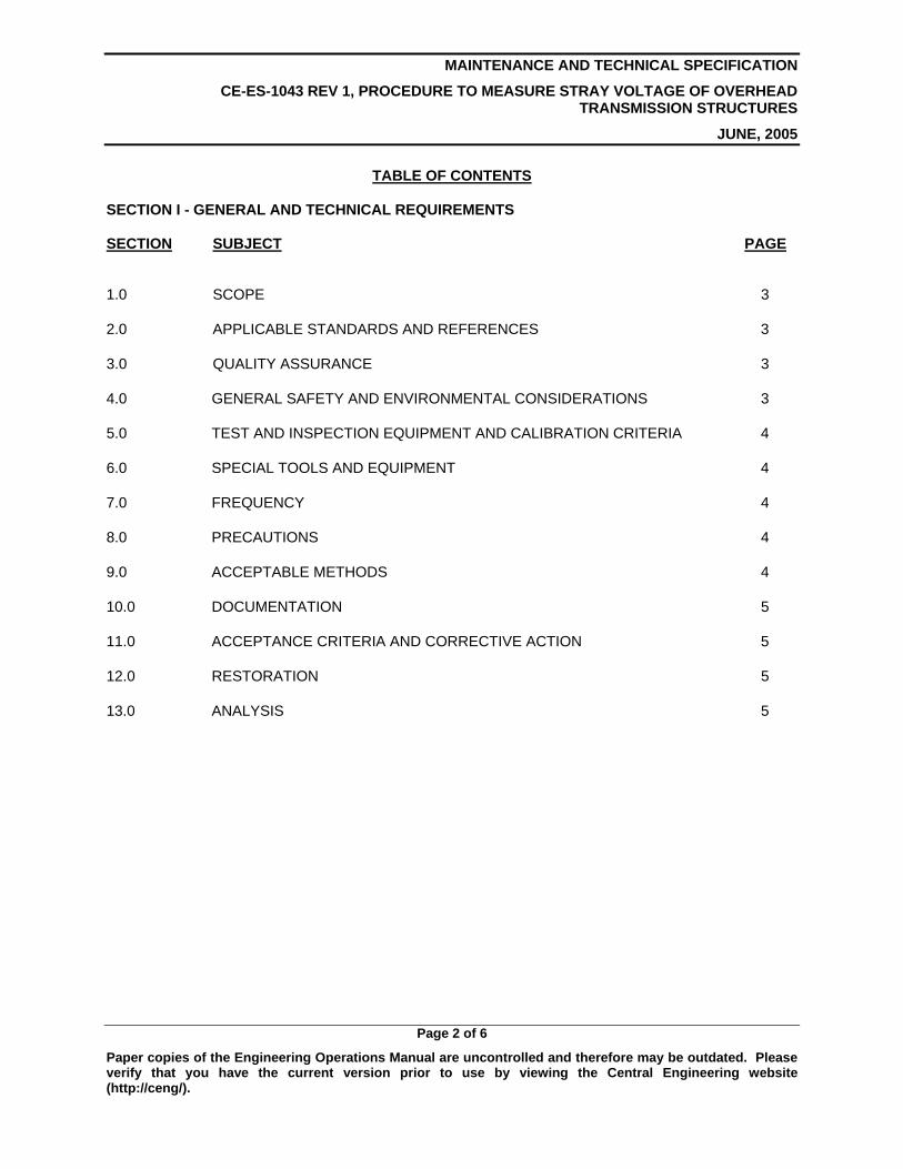
MAINTENANCE AND TECHNICAL SPECIFICATION
CE-ES-1043 REV 1, PROCEDURE TO MEASURE STRAY VOLTAGE OF OVERHEAD TRANSMISSION STRUCTURES
JUNE, 2005
Page 2 of 6
Paper copies of the Engineering Operations Manual are uncontrolled and therefore may be outdated. Please verify that you have the current version prior to use by viewing the Central Engineering website (http://ceng/).
TABLE OF CONTENTS SECTION I - GENERAL AND TECHNICAL REQUIREMENTS SECTION SUBJECT PAGE 1.0 SCOPE 3
2.0 APPLICABLE STANDARDS AND REFERENCES 3
3.0 QUALITY ASSURANCE 3
4.0 GENERAL SAFETY AND ENVIRONMENTAL CONSIDERATIONS 3
5.0 TEST AND INSPECTION EQUIPMENT AND CALIBRATION CRITERIA 4
6.0 SPECIAL TOOLS AND EQUIPMENT 4
7.0 FREQUENCY 4
8.0 PRECAUTIONS 4
9.0 ACCEPTABLE METHODS 4
10.0 DOCUMENTATION 5
11.0 ACCEPTANCE CRITERIA AND CORRECTIVE ACTION 5
12.0 RESTORATION 5
13.0 ANALYSIS 5
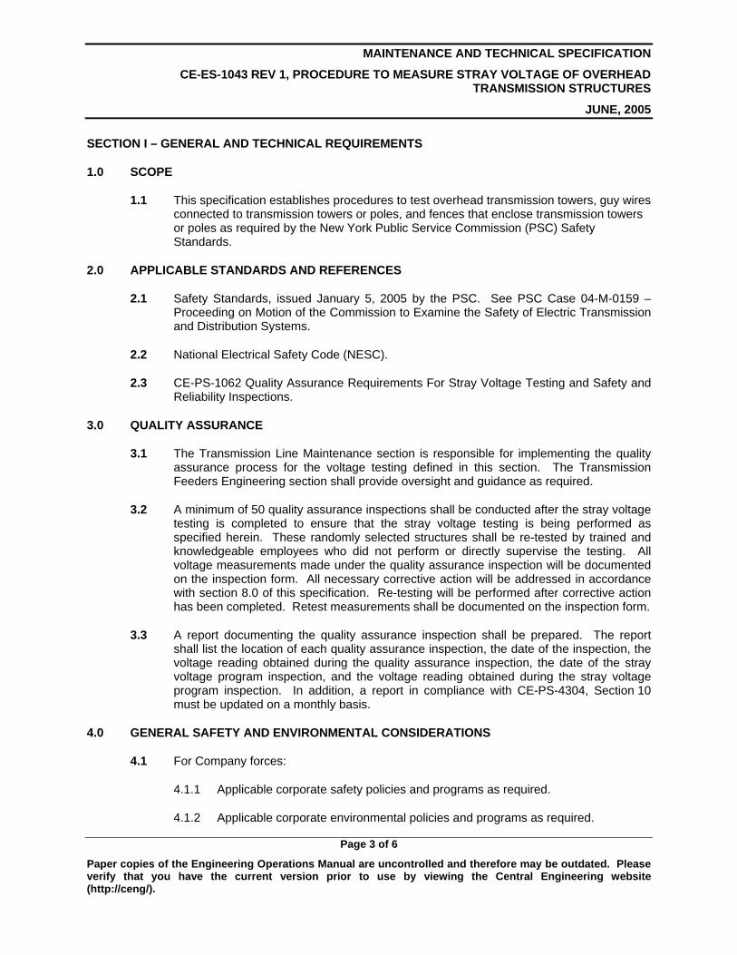
MAINTENANCE AND TECHNICAL SPECIFICATION
CE-ES-1043 REV 1, PROCEDURE TO MEASURE STRAY VOLTAGE OF OVERHEAD TRANSMISSION STRUCTURES
JUNE, 2005
Page 3 of 6
Paper copies of the Engineering Operations Manual are uncontrolled and therefore may be outdated. Please verify that you have the current version prior to use by viewing the Central Engineering website (http://ceng/).
SECTION I – GENERAL AND TECHNICAL REQUIREMENTS
1.0 SCOPE
1.1 This specification establishes procedures to test overhead transmission towers, guy wires connected to transmission towers or poles, and fences that enclose transmission towers or poles as required by the New York Public Service Commission (PSC) Safety Standards.
2.0 APPLICABLE STANDARDS AND REFERENCES
2.1 Safety Standards, issued January 5, 2005 by the PSC. See PSC Case 04-M-0159 – Proceeding on Motion of the Commission to Examine the Safety of Electric Transmission and Distribution Systems.
2.2 National Electrical Safety Code (NESC).
2.3 CE-PS-1062 Quality Assurance Requirements For Stray Voltage Testing and Safety and Reliability Inspections.
3.0 QUALITY ASSURANCE
3.1 The Transmission Line Maintenance section is responsible for implementing the quality assurance process for the voltage testing defined in this section. The Transmission Feeders Engineering section shall provide oversight and guidance as required.
3.2 A minimum of 50 quality assurance inspections shall be conducted after the stray voltage testing is completed to ensure that the stray voltage testing is being performed as specified herein. These randomly selected structures shall be re-tested by trained and knowledgeable employees who did not perform or directly supervise the testing. All voltage measurements made under the quality assurance inspection will be documented on the inspection form. All necessary corrective action will be addressed in accordance with section 8.0 of this specification. Re-testing will be performed after corrective action has been completed. Retest measurements shall be documented on the inspection form.
3.3 A report documenting the quality assurance inspection shall be prepared. The report shall list the location of each quality assurance inspection, the date of the inspection, the voltage reading obtained during the quality assurance inspection, the date of the stray voltage program inspection, and the voltage reading obtained during the stray voltage program inspection. In addition, a report in compliance with CE-PS-4304, Section 10 must be updated on a monthly basis.
4.0 GENERAL SAFETY AND ENVIRONMENTAL CONSIDERATIONS
4.1 For Company forces:
4.1.1 Applicable corporate safety policies and programs as required.
4.1.2 Applicable corporate environmental policies and programs as required.
MAINTENANCE AND TECHNICAL SPECIFICATION
CE-ES-1043 REV 1, PROCEDURE TO MEASURE STRAY VOLTAGE OF OVERHEAD TRANSMISSION STRUCTURES
JUNE, 2005
Page 4 of 6
Paper copies of the Engineering Operations Manual are uncontrolled and therefore may be outdated. Please verify that you have the current version prior to use by viewing the Central Engineering website (http://ceng/).
4.2 For Contract forces:
4.2.1 Applicable federal, state, and local regulations for safety requirements and additional Company policies as required.
4.2.2 Applicable federal, state, and local regulations for environmental requirements and additional Company policies as required.
5.0 TEST AND INSPECTION EQUIPMENT AND CALIBRATION CRITERIA
5.1 Fluke 77, Fluke 179 or an approved equal Testing Meter shall be used for stray voltage measurement.
5.2 The Testing Meter shall be calibrated as per manufacturer’s instructions.
5.3 Appendix A of the PSC Order requires “All equipment used for stray voltage testing must be certified by an independent test laboratory as being able to reliably detect voltages of 8 to 600 volts.”
6.0 SPECIAL TOOLS AND EQUIPMENT
6.1 None
7.0 FREQUENCY
7.1 All transmission towers, any guy wires connected to transmission towers or poles, and fences that enclose any tower or pole shall be tested for stray voltage every year.
7.2 All annual stray voltage testing must be completed by November 30 each year.
7.3 In addition, Company personnel will conduct stray voltage testing on transmission structures that are actively worked on at the beginning and end of each workday. If work is concluded at a particular structure during the workday, stray voltage testing will be done before the personnel leave the site, rather than at the end of the workday. Each stray voltage test shall be recorded on the daily work record (Daily Crew Activity Report). This data will be transferred to an electronic database.
7.3.1 Readings shall not be taken when difficult natural conditions exist, such as significant snow cover or ground frost.
8.0 PRECAUTIONS
8.1 None
9.0 ACCEPTABLE METHODS
9.1 The stray voltage shall be measured from the tower steel, guy wire or tower fence to ground. Where a system ground is not available a metal rod shall be driven into the earth to an approximate depth of 1 foot for a ground point.
MAINTENANCE AND TECHNICAL SPECIFICATION
CE-ES-1043 REV 1, PROCEDURE TO MEASURE STRAY VOLTAGE OF OVERHEAD TRANSMISSION STRUCTURES
JUNE, 2005
Page 5 of 6
Paper copies of the Engineering Operations Manual are uncontrolled and therefore may be outdated. Please verify that you have the current version prior to use by viewing the Central Engineering website (http://ceng/).
9.2 The Testing Meter shall be operated in accordance with the manufacturer’s instructions.
10.0 DOCUMENTATION
10.1 Test crews shall complete appropriate test forms, which enumerates each item to be tested. The voltage reading shall be recorded on the appropriate form.
10.2 The Transmission Line Maintenance section shall process and maintain the completed forms and ensure that all structures have been tested each year and corrective repairs have been made. The Transmission Feeders Engineering section shall review the test results and recommend corrective action for locations that do not meet the acceptance criteria defined herein.
11.0 ACCEPTANCE CRITERIA AND CORRECTIVE ACTION
11.1 Measured stray voltage from tower steel, guy wire or tower fence to ground exceeding 8 volts is not acceptable.
11.2 Corrective action shall be taken on the facility where stray voltage is measured greater than 8 volts. If the condition causing the voltage cannot be repaired immediately, the structure must be made safe, for example, by use of a temporary ground rod, or continuously guarded by personnel to prevent access by the public until the structure can be made safe or permanently repaired. Permanent repair shall be made within 45 days.
12.0 RESTORATION
12.1 After completion of work, all temporary grounds and associated equipment or connections shall be removed.
13.0 ANALYSIS
13.1 None

MAINTENANCE AND TECHNICAL SPECIFICATION
CE-ES-1043 REV 1, PROCEDURE TO MEASURE STRAY VOLTAGE OF OVERHEAD TRANSMISSION STRUCTURES
JUNE, 2005
Page 6 of 6
Paper copies of the Engineering Operations Manual are uncontrolled and therefore may be outdated. Please verify that you have the current version prior to use by viewing the Central Engineering website (http://ceng/).
Maintenance and Inspection Specification
SECTION II – TEST DATA AND ACCEPTANCE REQUIREMENTS AND
SUPPLEMENTAL SPECIFICATIONS
PART 0 – (Data Sheets, Tables and Lists)
1.0 Not Applicable.
PART 1 – (Supplemental Specifications)
1.0 Not Applicable.
. . . . . . .. . .
88
This page is intentionally left blank.
89
I: Overhead Transmission Facility Inspection Specification


. . . . . . .. . .
90
This page is intentionally left blank.
91
J: Substations Stray Voltage Testing and Inspection Procedure
SUBSTATION OPERATIONS PROCEDURE
SUBJECT: SUBSTATIONS STRAY VOLTAGE TESTING AND STATION INSPECTION PROCEDURE NO.: 0800-0038/00 DATE ISSUED: 10/05 REVISED BY: Anthony Natale / Nick Deninno PAGE: 1 of 8 APPROVED: JOSEPH SUSCO
1.0 PURPOSE
1.1 To establish a procedure for Substation Operations’ compliance with Public Service Commission Electric Safety Standards that require (1) annual voltage testing of publicly accessible structures that may become energized as a result of stray voltage and (2) five-year visual inspection of electric equipment for safety and reliability. This procedure requires testing for electric potential (voltage testing) on steel, aluminum or other electrical conducting materials on substations where such materials are accessible to the general public. These include but are not limited to fences, doors, roll-up gates, metallic delivery boxes, dielectric fluid delivery ports and Siamese connections that may become energized as a result of stray voltage. This procedure also requires visual inspection of all equipment in substations and cooling plants on a five-year cycle.
2.0 APPLICATION
2.1 This procedure applies to all transmission and sub-transmission substations and cable-cooling plants.
3.0 DEFINITIONS and REQUIREMENTS
3.1 Substation Testing - Stray voltage testing of perimeter fencing and other electrical conductive materials of substations where such materials are accessible to the general public. The surface of electrical conductive materials on all station perimeters will be tested annually using an approved tester (i.e., glow, no glow). The direct contact low voltage tester (LV-S-5) detects voltages above 5 volts (indicated by a glow of the device). Since the Public Service Commission’s standards require testing for voltage of 8 volts and higher, if the device does not glow, no further testing is required at a test point. If the device glows, a fluke meter will be used to obtain a numerical reading. If there is any voltage reading (above 0 volts), then the location shall be guarded until the voltage is eliminated (temporary grounding may be used). Permanent repairs will be made within 45 days. All fence lines, entrance doors, transformer vault enclosures and any metal exterior trimmings, which have the potential to conduct electricity and are accessible to the public, must be tested once during each 12-month period ending November 30.
3.2 Station Inspection – A careful visual safety and reliability examination of substation and cooling plant equipment for conditions that have the potential to cause or lead to safety hazards or failure of the equipment. All equipment in a substation or cooling plants will be inspected by visual examination once
SUBJECT: SUBSTATIONS STRAY VOLTAGE TESTING AND STATION INSPECTION
INSTRUCTION NO.: 0800-00038/00 PAGE: 2 of 8
every five years, and at least 20% of the substations and cooling stations will be inspected each year. These inspections are separate and in addition to the periodic visual and/or maintenance functions that SSO performs on a periodic basis through compliance inspections such as battery room inspections, deluge room inspections, quarterly pump house, circulation plant and PURS inspections, pothead inspections, overhead tower inspections, and load board inspections.
4.0 STRAY VOLTAGE PROCEDURE
4.1 Required Permits and Training.
a. Authorized personnel who conduct stray voltage testing on equipment described in section 1.1 are not required to obtain an Area Work Permit. But must be familiar with the workings and procedures of a substation.
b. Authorized personnel prior to conducting the stray voltage testing and station inspections as described in section 1.1 are required to take the OJT training listed as CSG0020 STRAY VOLTAGE TRAINING & TESTING SSO under the Learning Center courses.
4.2 Proper PPE
a. In addition to other station-required PPE, no additional PPE is required for personnel that conduct stray voltage testing.
4.3 Testing Devices & Equipment:
a. All substation perimeters will be tested annually using the Low Voltage Tester Device (LV-S-5).
b. The test device should be checked for proper operation prior to the start of testing, periodically during the day, and at the end of the test day.
c. A fluke meter will be used to obtain a numerical reading when the Low Voltage Tester detects voltage.
d. A 50’ length of 12 AWG insulated wire (with alligator clips) will be needed in order to connect the ground lead of the Fluke device to a ground source. (Note: obtain a length of 12 AWG necessary to accommodate a proper ground reference)
e. Fluke Meter Device Settings:
(1) The black lead on the meter should be connected to the terminal marked (Com) and the red lead should be connected to the terminal marked (V).
(2) The Multi-Meter dial indicator should be set in the A/C Voltage measurement setting, with a sensitivity that can detect 1V to 500V.
SUBJECT: SUBSTATIONS STRAY VOLTAGE TESTING AND STATION INSPECTION
INSTRUCTION NO.: 0800-00038/00 PAGE: 3 of 8
4.4 Conducting Stray Voltage Testing:
a. Stray voltage testing at each station will be conducted according to stray voltage testing rounds that are established in Maximo. The results of the stray voltage test at each testing point shall be recorded in Maximo.
b. Whenever possible, exterior substation structures that are
accessible to the public will be tested from the interior of the substation. For example, a roll-up gate will be tested by applying the test device to a test point on the interior of the door, and a metal chain link fence will be tested by applying the test device to fence test points while standing on the interior side of the fence.
c. All continuous structures that comprise conductive materials
shall be tested at 40’ intervals (i.e. perimeter fencing). d. Touch the approved Test Device (Glow / No Glow) to
substation exterior structures made of materials that can conduct electricity and are accessible to the public. These structures include but are not limited to fences, doors, roll-up gates, metallic delivery boxes, dielectric fluid delivery ports and Siamese connections that may become energized as a result of stray voltage. If at any point the device glows when in contact with a conducting or non-conducting section, follow the procedures stated in item 4.5 “POSITVE TEST RESULTS”. If a no glow condition exists then proceed to next test point.
4.5 Positive Test Results of a Stray Voltage Test:
a. If at any time the test device indicates a voltage (glows), a Fluke Meter reading will be taken to confirm and identify the severity of the stray voltage condition.
b. Connect a 12 AWG insulated wire to a Substation ground cable
or OSHA ball stud. A fire hydrant may also be used as a ground reference for tests conducted on the exterior of the Station beyond the reach of a ground cable or OSHA ball stud.
(1) Attach the black lead from a Fluke Meter to the free
end of the 12 AWG insulated wire.
(2) Set the Fluke Meter multi-meter to test continuity and touch the ground source that the 12 AWG insulated wire is attached to with the tip of the red lead. If the integrity of the 12 AWG wire has not been compromised the reading should be zero.
(3) In the event continuity in the lead cannot be
established by the required method, obtain another 12 AWG insulated wire or Fluke Multi-Meter if necessary.
(4) Once continuity has been established, move the
selector to the AC voltage setting and use the tip of
SUBJECT: SUBSTATIONS STRAY VOLTAGE TESTING AND STATION INSPECTION
INSTRUCTION NO.: 0800-00038/00 PAGE: 4 of 8
the red lead connected to the multi-meter to test the exposed portion of the potential conductor.
(5) Obtain an accurate reading of the measured stray
voltage. Record the location and the reading.
(6) When a stray voltage condition is found the station operator will be informed immediately. The station operator will contact the Control Center Shift manager immediately.
c. Temporary safety measures will require the application of
portable grounds to the affected area.
d. Following the application of the portable grounds, the area will be tested again to ensure that no stray voltage is detected.
e. In the event that a stray voltage condition cannot be
resolved, means shall be implemented to shield the public from the condition until it can be resolved.
4.6 Repairs of a Stray Voltage Condition:
a. Repairs shall be made in accordance with EI 2002-10,latest revision that discusses the means and material required to properly address deficiencies in the station ground grid.
b. Stray Voltage conditions that can be resolved (i.e. tighten a strap, etc.) do not require further action. If the condition cannot be resolved, it shall be recorded in Maximo, temporary measures applied (i.e. temporary/portable ground) and permanent repairs made within 45 days.
4.7 Tracking of an Exterior Stray Voltage Test:
a. The conduct of each stray voltage testing Auto Tour round shall be recorded in Maximo. An associated Auto Tour round or job plan shall be completed identifying the test results – either negative (no stray voltage) or test failure. Any positive reading that can’t be resolved constitutes a test failure.
(1) A test failure requires personnel to record a positive
reading along with its location in Maximo.
(2) A new Maximo Work Order shall be created with a work type of SVTR (Stray Voltage Testing Repair). A Maximo tag will be used to reference the affected area when follow-up work is required.
5.0 Station Inspection:
5.1 All equipment in each substation and cable cooling plants will be visually inspected once every five years.

SUBJECT: SUBSTATIONS STRAY VOLTAGE TESTING AND STATION INSPECTION
INSTRUCTION NO.: 0800-00038/00 PAGE: 5 of 8
5.2 Inspections will be conducted according to inspection rounds for the “equipment categories” at each station or plant as established in Maximo. The equipment categories to be visually inspected are battery room, deluge room, pump house, circulation plant, PURS, pothead, overhead tower, load board, control rooms, relay cubicles (interior and exterior), alarm panels, circuit breaker cabinets (transmission and distribution voltage levels), transformers, station yards and interior switch rooms.
5.3 The individual equipment within each equipment category at each station will be visually inspected for any condition that has the potential to cause or lead to safety hazards or failure of the equipment. Among the conditions to be identified are exposed conductors, corrosion, frayed/damaged insulation, foreign material intrusion, water leaks, and grounding connections. For example, all equipment within a relay cubicle will be visually inspected.
5.4 The results of the inspection of each equipment category at a station shall be recorded in Maximo and each equipment deficiency will be recorded. An associated Auto Tour round or job plan will be completed, identifying the inspection results.
5.5 Structures containing equipment, whether locked or not, must be opened and the equipment visually inspected. Disassembly of panels and cubicles is not required, only doors and openings normally meant to be accessible and operated during operations or maintenance are required to be opened. Sealed structures will not be opened.
5.6 All environmental or safety problems shall be immediately reported to the station operator. They will notify the Control Center Shift Manager. All other items found during the inspection will be recorded in Maximo. A new Maximo Work order will be generated to make the appropriate repairs.
6.0 Quality Assurance
6.1 Substation Operations shall use this procedure and Maximo as the
record keeping and tracking mechanism to implement the required testing and inspections.
6.2 Substation Operations will implement a quality assurance program
and responsibilities to ensure that actions mandated under the above referenced PSC Electric Safety Standards are completed.
6.3 Substation Operations’ quality assurance program will conduct
periodic document reviews and field observations throughout the year to ensure that 100% of the required stray voltage tests and a minimum of 20% of the Safety and Reliability Inspections will be completed by November 30 of each year and that 100% of substation and cooling plant equipment is inspected every five years.
6.4 Substation Operations will assess annually the causes of stray
voltage in substations and cooling plants, identify preventative and remedial measures, and establish a plan to implement such measures.
SUBJECT: SUBSTATIONS STRAY VOLTAGE TESTING AND STATION INSPECTION
INSTRUCTION NO.: 0800-00038/00 PAGE: 6 of 8
6.5 Substation Operations shall prepare an annual report summarizing.
a. The status of their test and inspection programs, including test and inspection results.
b. The activities required by section 6.4
c. This report will be available to the Law Department by December 15th in support of the Company’s January 15th annual report to the PSC addressing the Company-wide testing and inspection program.
6.6 The elements to be reviewed as part of the quality assurance program are noted in Section 4.0 and 5.0 of this procedure. The periodic reviews are not intended to cover every element and item of the program, but over the period of the year all elements should be reviewed. A minimum of 10% of the SV Testing and Station Inspections completed should be checked yearly.
7.0 RESPONSIBILITES
7.1 The MAXIMO Manager will be responsible for establishing and updating, as necessary, Auto Tour rounds in Maximo to implement the stray voltage testing and inspection programs.
7.2 The MAXIMO Manager in the interim, until the Quality Assurance Group is developed will be responsible for developing, updating, as necessary, and implementing the annual Quality Assurance Program.
7.3 The MAXIMO Manager will be responsible for conducting the assessment and planning required by section 6.4.
7.4 Area Managers will be responsible for the completion of the annual stray voltage tests and required critical visual inspections.
7.5 Central Engineering will act as the Subject Matter Expert (SME) in the installation and/or repair of the Stations ground grid.
7.6 The Control Center Shift Manager will serve as the information coordinator and default contact in the case where Engineering is not readily available.
7.7 The Station Operator will serve to contact the necessary required individuals and to perform temporary safety measures to protect or isolate the affected area.
8.0 EXHIBITS
8.1 Exhibit A – Stray Voltage Test Device.
9.0 REFERENCES
9.1 PSC Case 04-M-0159 – Proceeding on Motion of the Commission to Examine the Safety of Electric Transmission and Distribution
SUBJECT: SUBSTATIONS STRAY VOLTAGE TESTING AND STATION INSPECTION
INSTRUCTION NO.: 0800-00038/00 PAGE: 7 of 8
Systems, “Order Instituting Safety Standards,” issued January 5, 2005.
9.2 CE-ES 2002 – Standard Engineering Design Guidelines for Area And Transmission Substations, Section III, part 10.
http://ceng/ceng/specs/se/CE-ES-2002-10.pdf
9.3 SSO OJT Training CSG0020 “STRAY VOLTAGE TRAINING & TESTING SSO”.
SSO_SV_OJT Presentation
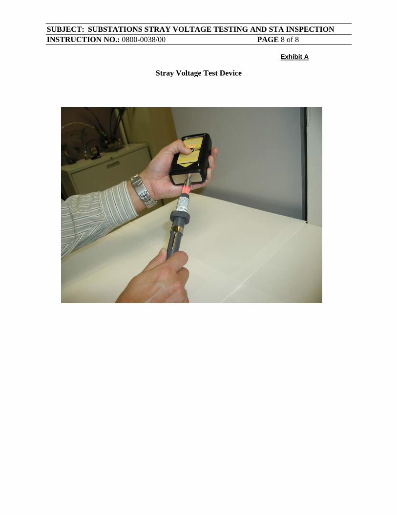
SUBJECT: SUBSTATIONS STRAY VOLTAGE TESTING AND STA INSPECTION INSTRUCTION NO.: 0800-0038/00 PAGE 8 of 8
Exhibit A
Stray Voltage Test Device

. . . . . . .. . .
92
This page is intentionally left blank.

93
K: EO-10,790 (Insp. & Maint. Schedule For 4 kV Unit & Multi-Bank SS Transf. & Switchgear

CONSOLIDATED EDISON CO. OF NEW YORK INC. 4 IRVING PLACE
NEW YORK, N.Y. 10003
DISTRIBUTION ENGINEERING DEPARTMENT
SUBSTATION AND EQUIPMENT SECTION
SPECIFICATION EO-10790 REVISION 1
MARCH. 2001
INSPECTION AND MAINTENANCE SCHEDULE FOR 4 KV UNIT AND MULTI-BANK SUBSTATION TRANSFORMERS AND SWITCHGEAR
FILE: INSPECTION AND MAINTENANCE MANUAL NO. 1
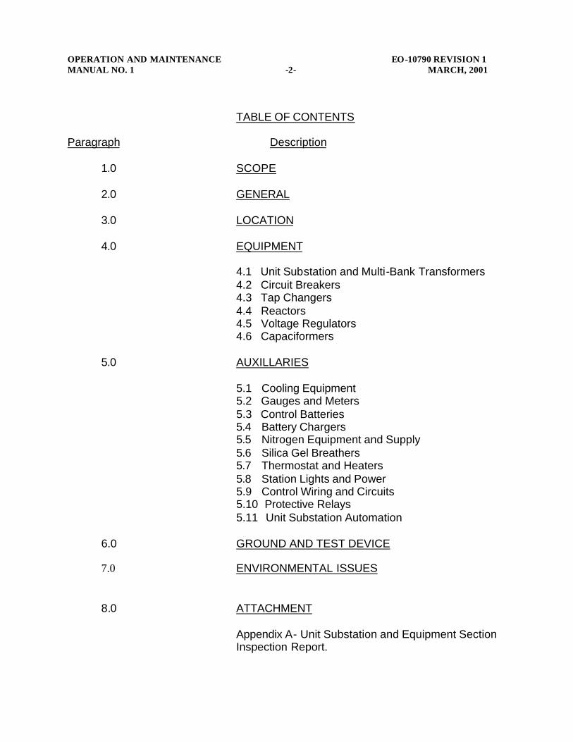
OPERATION AND MAINTENANCE EO-10790 REVISION 1 MANUAL NO. 1 -2- MARCH, 2001 TABLE OF CONTENTS Paragraph Description 1.0 SCOPE 2.0 GENERAL 3.0 LOCATION 4.0 EQUIPMENT
4.1 Unit Substation and Multi-Bank Transformers 4.2 Circuit Breakers 4.3 Tap Changers 4.4 Reactors 4.5 Voltage Regulators 4.6 Capaciformers 5.0 AUXILLARIES 5.1 Cooling Equipment 5.2 Gauges and Meters 5.3 Control Batteries
5.4 Battery Chargers 5.5 Nitrogen Equipment and Supply 5.6 Silica Gel Breathers 5.7 Thermostat and Heaters 5.8 Station Lights and Power 5.9 Control Wiring and Circuits 5.10 Protective Relays 5.11 Unit Substation Automation
6.0 GROUND AND TEST DEVICE 7.0 ENVIRONMENTAL ISSUES
8.0 ATTACHMENT
Appendix A- Unit Substation and Equipment Section Inspection Report.
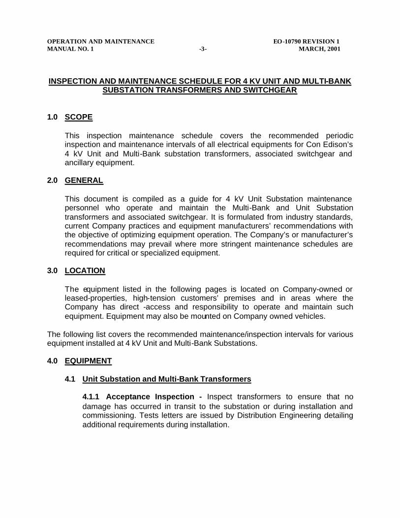
OPERATION AND MAINTENANCE EO-10790 REVISION 1 MANUAL NO. 1 -3- MARCH, 2001 INSPECTION AND MAINTENANCE SCHEDULE FOR 4 KV UNIT AND MULTI-BANK
SUBSTATION TRANSFORMERS AND SWITCHGEAR
1.0 SCOPE
This inspection maintenance schedule covers the recommended periodic inspection and maintenance intervals of all electrical equipments for Con Edison’s 4 kV Unit and Multi-Bank substation transformers, associated switchgear and ancillary equipment.
2.0 GENERAL
This document is compiled as a guide for 4 kV Unit Substation maintenance personnel who operate and maintain the Multi-Bank and Unit Substation transformers and associated switchgear. It is formulated from industry standards, current Company practices and equipment manufacturers’ recommendations with the objective of optimizing equipment operation. The Company’s or manufacturer’s recommendations may prevail where more stringent maintenance schedules are required for critical or specialized equipment.
3.0 LOCATION
The equipment listed in the following pages is located on Company-owned or leased-properties, high-tension customers’ premises and in areas where the Company has direct -access and responsibility to operate and maintain such equipment. Equipment may also be mounted on Company owned vehicles.
The following list covers the recommended maintenance/inspection intervals for various equipment installed at 4 kV Unit and Multi-Bank Substations.
4.0 EQUIPMENT 4.1 Unit Substation and Multi-Bank Transformers
4.1.1 Acceptance Inspection - Inspect transformers to ensure that no damage has occurred in transit to the substation or during installation and commissioning. Tests letters are issued by Distribution Engineering detailing additional requirements during installation.

OPERATION AND MAINTENANCE EO-10790 REVISION 1 MANUAL NO. 1 -4- MARCH, 2001
4.1.2 Warranty Inspection - All equipment is to be checked within 12 months after energization, or for an extended period agreed upon between Con Edison and the manufacturer for defects or damage which may be covered by warranty.
4.1.3 Periodic inspection - Periodic inspection of all Unit and Multi-Bank Substations for general station conditions shall be completed every two months. Items to be checked are included in Appendix A. Completed form (Unit Substation And Equipment Section Inspection Report) should be submitted to and retained by the local Supervisor.
4.1.4 Oil Samples - Oil samples are to be taken annually from all oil filled compartments and sent to the Chemical Lab for DGOA and dielectric strength.
4.2 Circuit Breakers
4.2.1 Transformer and Feeder Circuit Breakers - Periodic maintenance of transformer and feeder circuit breakers is required every 500 operations or every three years. If required, the operating mechanism should be overhauled and all worn parts replaced. Refer to the manufacturer’s instruction manuals/EI Specification for detailed installation and maintenance tests guidelines for each breaker type.
Note: In addition to the inspection requirements listed above, all breakers which experience an open auto that results in a lockout coupled with an instantaneous relay operation should have a visual inspection performed prior to being returned to service.
4.2.3 Low Voltage Circuit Breakers - During periodic inspections of associated equipment the 120V or 240V breakers should be inspected and switched to the ON/OFF positions to ensure that they work.
4.3 Tap Changers
4.3.1 Primary (De-energized Tap Changer) - Whenever the de-energized tap changer is repositioned a transformer turns ratio test shall be performed. 4.3.2 Secondary (LTC) - Periodic inspections shall be carried out at the end of first year of operation and every three years thereafter.
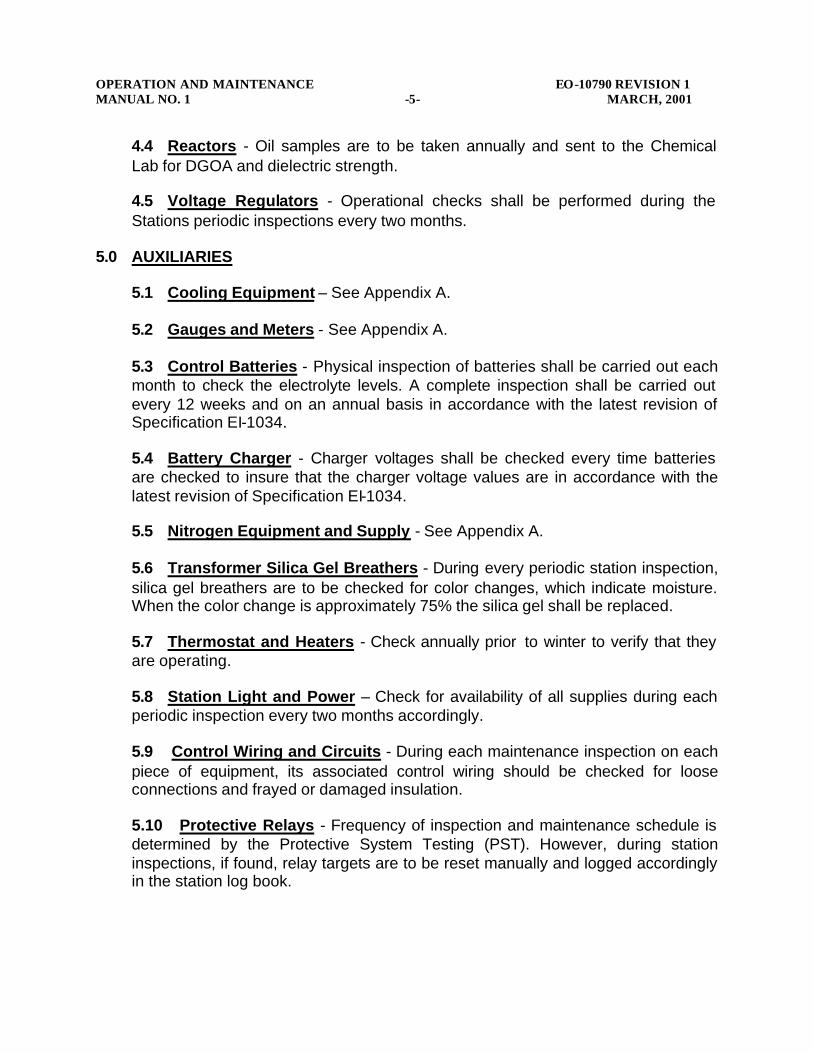
OPERATION AND MAINTENANCE EO-10790 REVISION 1 MANUAL NO. 1 -5- MARCH, 2001
4.4 Reactors - Oil samples are to be taken annually and sent to the Chemical Lab for DGOA and dielectric strength. 4.5 Voltage Regulators - Operational checks shall be performed during the Stations periodic inspections every two months.
5.0 AUXILIARIES 5.1 Cooling Equipment – See Appendix A.
5.2 Gauges and Meters - See Appendix A. 5.3 Control Batteries - Physical inspection of batteries shall be carried out each month to check the electrolyte levels. A complete inspection shall be carried out every 12 weeks and on an annual basis in accordance with the latest revision of Specification EI-1034. 5.4 Battery Charger - Charger voltages shall be checked every time batteries are checked to insure that the charger voltage values are in accordance with the latest revision of Specification EI-1034. 5.5 Nitrogen Equipment and Supply - See Appendix A. 5.6 Transformer Silica Gel Breathers - During every periodic station inspection, silica gel breathers are to be checked for color changes, which indicate moisture. When the color change is approximately 75% the silica gel shall be replaced. 5.7 Thermostat and Heaters - Check annually prior to winter to verify that they are operating. 5.8 Station Light and Power – Check for availability of all supplies during each periodic inspection every two months accordingly. 5.9 Control Wiring and Circuits - During each maintenance inspection on each piece of equipment, its associated control wiring should be checked for loose connections and frayed or damaged insulation. 5.10 Protective Relays - Frequency of inspection and maintenance schedule is determined by the Protective System Testing (PST). However, during station inspections, if found, relay targets are to be reset manually and logged accordingly in the station log book.
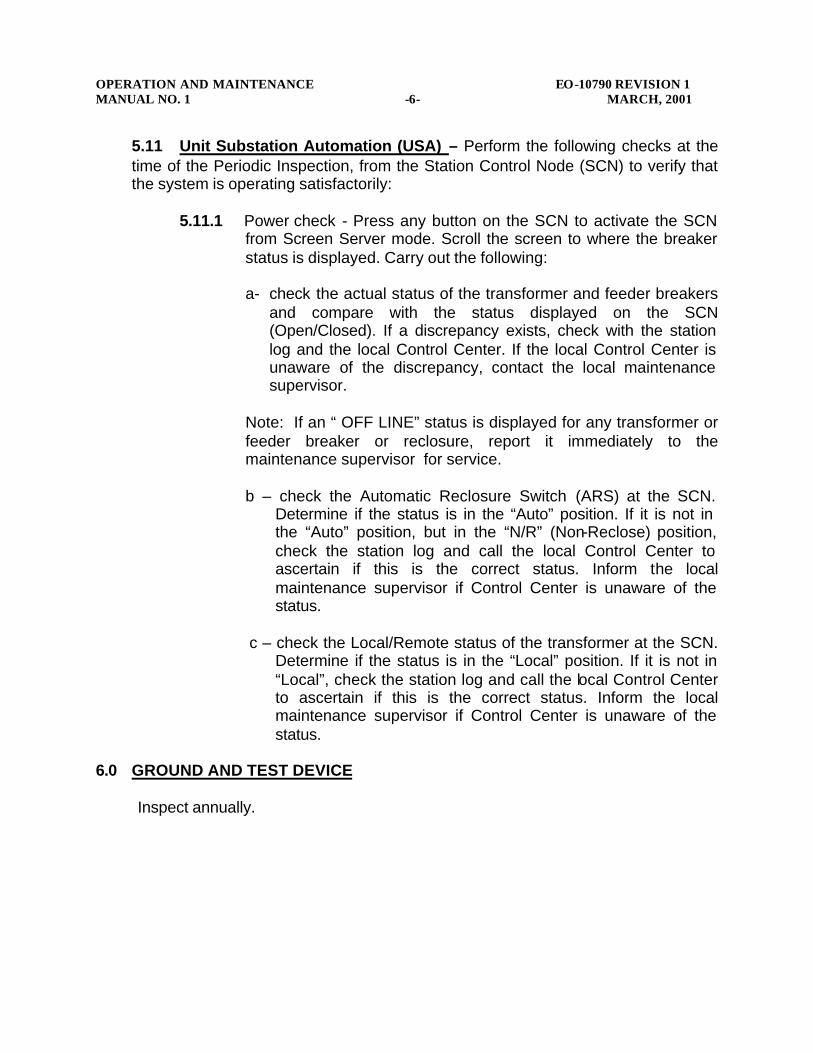
OPERATION AND MAINTENANCE EO-10790 REVISION 1 MANUAL NO. 1 -6- MARCH, 2001
5.11 Unit Substation Automation (USA) – Perform the following checks at the time of the Periodic Inspection, from the Station Control Node (SCN) to verify that the system is operating satisfactorily:
5.11.1 Power check - Press any button on the SCN to activate the SCN from Screen Server mode. Scroll the screen to where the breaker status is displayed. Carry out the following:
a- check the actual status of the transformer and feeder breakers
and compare with the status displayed on the SCN (Open/Closed). If a discrepancy exists, check with the station log and the local Control Center. If the local Control Center is unaware of the discrepancy, contact the local maintenance supervisor.
Note: If an “ OFF LINE” status is displayed for any transformer or feeder breaker or reclosure, report it immediately to the maintenance supervisor for service. b – check the Automatic Reclosure Switch (ARS) at the SCN.
Determine if the status is in the “Auto” position. If it is not in the “Auto” position, but in the “N/R” (Non-Reclose) position, check the station log and call the local Control Center to ascertain if this is the correct status. Inform the local maintenance supervisor if Control Center is unaware of the status.
c – check the Local/Remote status of the transformer at the SCN.
Determine if the status is in the “Local” position. If it is not in “Local”, check the station log and call the local Control Center to ascertain if this is the correct status. Inform the local maintenance supervisor if Control Center is unaware of the status.
6.0 GROUND AND TEST DEVICE
Inspect annually.
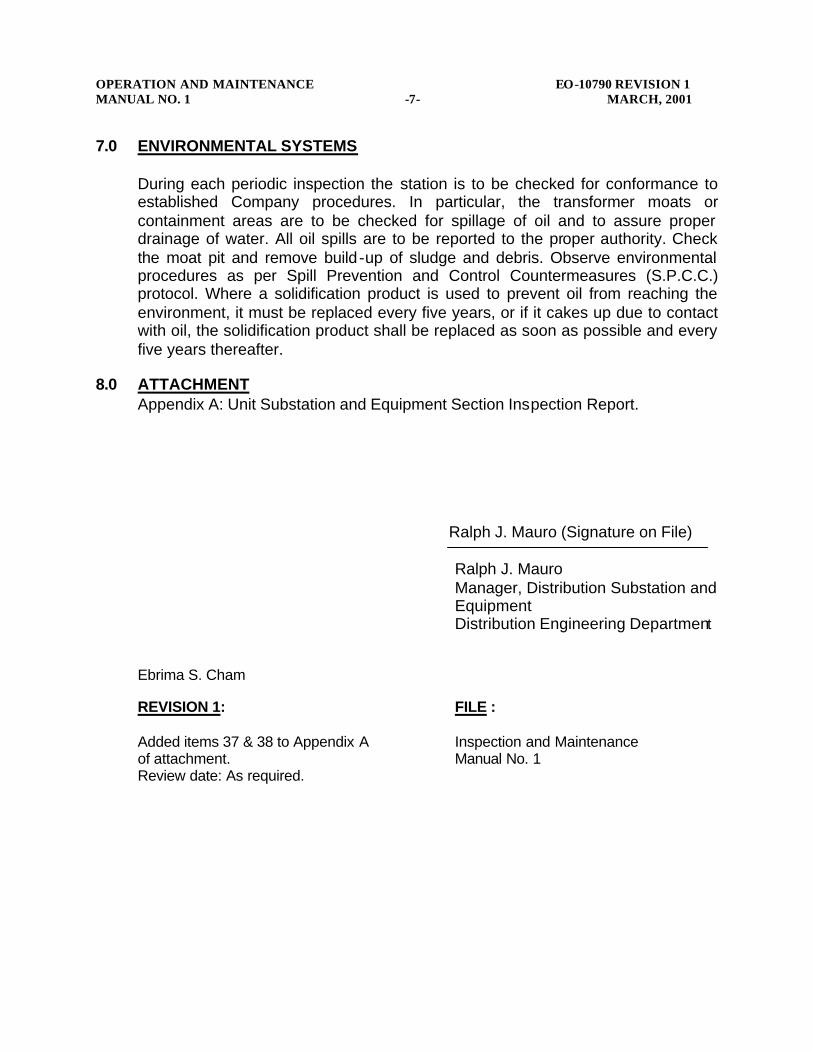
OPERATION AND MAINTENANCE EO-10790 REVISION 1 MANUAL NO. 1 -7- MARCH, 2001 7.0 ENVIRONMENTAL SYSTEMS
During each periodic inspection the station is to be checked for conformance to established Company procedures. In particular, the transformer moats or containment areas are to be checked for spillage of oil and to assure proper drainage of water. All oil spills are to be reported to the proper authority. Check the moat pit and remove build -up of sludge and debris. Observe environmental procedures as per Spill Prevention and Control Countermeasures (S.P.C.C.) protocol. Where a solidification product is used to prevent oil from reaching the environment, it must be replaced every five years, or if it cakes up due to contact with oil, the solidification product shall be replaced as soon as possible and every five years thereafter.
8.0 ATTACHMENT Appendix A: Unit Substation and Equipment Section Inspection Report.
Ralph J. Mauro (Signature on File)
Ralph J. Mauro Manager, Distribution Substation and Equipment Distribution Engineering Department
Ebrima S. Cham REVISION 1: FILE : Added items 37 & 38 to Appendix A Inspection and Maintenance of attachment. Manual No. 1 Review date: As required.

Page 1 Of 2
Unit Substation And Equipment Section Inspection ReportElectric Operation Organization: Substation:
Substation Operator: Employee ID #:
Inspection Date: Print # :
FOLLOW GUIDELINES ON REVERSE SIDE TO COMPLETE INSPECTIONS = SATISFACTORY U = UNSATISFACTORY T = NOTIFIED DISPATCHER
CHECKS S U T CHECKS S U T1. BATTERIES 20 GAUGES [TEMPERATURE]2. RECTIFIER 21 GAUGES [OIL]3. NITRO SYSTEM 22 GROUND AND TEST DEVICE4. OIL LEVELS 23 STATION LADDER5. OIL LEAKS 24 ONE LINE DIAGRAM6. FIRE EXTINGUISHERS 25 STATION PORTABLE GROUNDS7. EXTERIOR LIGHTING 26 PCB KIT8. INTERIOR LIGHTING 27 SIGNS9. HEATER 28 HOUSEKEEPING10. TELEPHONE LINE 29 TRANSFORMER COOLING KIT11. FEEDER AMMETER 30 CYCLONE FENCE12. FEEDER INDIC. LGTS. 31 LOCKS [SECURITY]13. TRANSFORMER GROUNDS 32 ADEMCO14. FENCE GROUNDS 33 TAP CHANGER15. WATER COOLING SYST. 34 BREAKER DOLLIE16. WATER PIT 35 USA17. NEONS 36 SELICA GEL18 COOLING FANS Multi-Bank Substations Only19 BLUESTONE (Transf. pit) 37 CE/FD WHITE HARD HAT SIGN
38 WHITE HARD HAT
OPERATIONAL CHECKS - Cubicle #
January 4 May 8 September 5 CubicleFebruary 5 June 4 October 6 FeederMarch 6 July None November 7 Counter ReadingApril 7 August None December 8 Operational Check
FeedersFEEDERAMMETER READINGCOUNTER READING
TAP CHANGER COUNTER READING SETTINGS: R X
TRANSFORMER OIL LEVELS AND TEMP. READINGSCOMPARTMENT OIL LEVELWINDING TEMP. MAX TEMP.
MAIN BODY RECTIFIERTAP CHANGER As Specified As Found As Left
PRIMARY D.C. VOLTAGECAPACIFORMER D.C. AMP
NITRO PRESSURE: CONSERVATOR PRESSURE________ NITRO PRESSURE (To Transformer)_________
REMARKS:
Operator's Signature Supervisor's Signature
APPENDIX A
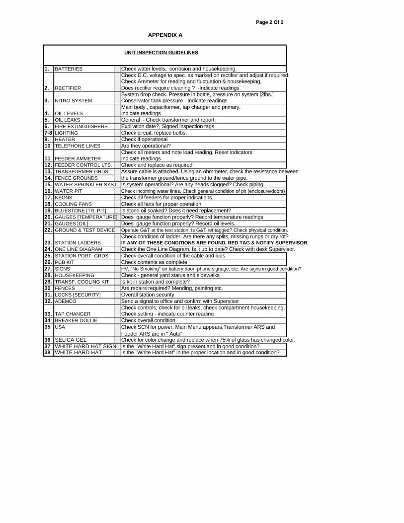
Page 2 Of 2
UNIT INSPECTION GUIDELINES
1. BATTERIES Check water levels, corrosion and housekeeping.Check D.C. voltage to spec. as marked on rectifier and adjust if required.Check Ammeter for reading and fluctuation & housekeeping,
2. RECTIFIER Does rectifier require cleaning ? -Indicate readingsSystem drop check. Pressure in bottle, pressure on system [2lbs.]
3. NITRO SYSTEM Conservator tank pressure - Indicate readingsMain body , capaciformer, tap changer and primary.
4. OIL LEVELS Indicate readings5. OIL LEAKS General - Check transformer and report.6. FIRE EXTINGUISHERS Expiration date?, Signed inspection tags7-8 LIGHTING Check circuit, replace bulbs. 9. HEATER Check if operational10 TELEPHONE LINES Are they operational?
Check all meters and note load reading. Reset indicators11 FEEDER AMMETER Indicate readings12. FEEDER CONTROL LTS. Check and replace as required13. TRANSFORMER GRDS. Assure cable is attached. Using an ohmmeter, check the resistance between14. FENCE GROUNDS the transformer ground/fence ground to the water pipe.15. WATER SPRINKLER SYST. Is system operational? Are any heads clogged? Check piping16. WATER PIT Check incoming water lines. Check general condition of pit (enclosure/doors) 17. NEONS Check all feeders for proper indications.18. COOLING FANS Check all fans for proper operation19. BLUESTONE [TR. PIT] Is stone oil soaked? Does it need replacement?20. GAUGES [TEMPERATURE] Does gauge function properly? Record temperature readings21. GAUGES [OIL] Does gauge function properly? Record oil levels.22. GROUND & TEST DEVICE Operate G&T at the test station. Is G&T ref tagged? Check physical condition.
Check condition of ladder. Are there any splits, missing rungs or dry rot?23. STATION LADDERS IF ANY OF THESE CONDITIONS ARE FOUND, RED TAG & NOTIFY SUPERVISOR.24. ONE LINE DIAGRAM Check the One Line Diagram. Is it up to date? Check with desk Supervisor.25. STATION PORT. GRDS. Check overall condition of the cable and lugs 26. PCB KIT Check contents as complete27. SIGNS HV, "No Smoking" on battery door, phone signage, etc. Are signs in good condition?28. HOUSEKEEPING Check - general yard status and sidewalks29. TRANSF. COOLING KIT Is kit in station and complete?30 FENCES Are repairs required? Mending, painting etc.31. LOCKS [SECURITY] Overall station security32. ADEMCO Send a signal to office and confirm with Supervisor
Check controls, check for oil leaks, check compartment housekeeping, 33. TAP CHANGER Check setting - indicate counter reading34 BREAKER DOLLIE Check overall condition35 USA
36 SELICA GEL Check for color change and replace when 75% of glass has changed color.37 WHITE HARD HAT SIGN Is the "White Hard Hat" sign present and in good condition?38 WHITE HARD HAT Is the "White Hard Hat" in the proper location and in good condition?
Check SCN for power, Main Menu appears,Transformer ARS and Feeder ARS are in " Auto"
APPENDIX A

. . . . . . .. . .
94
L: HD Test Reports
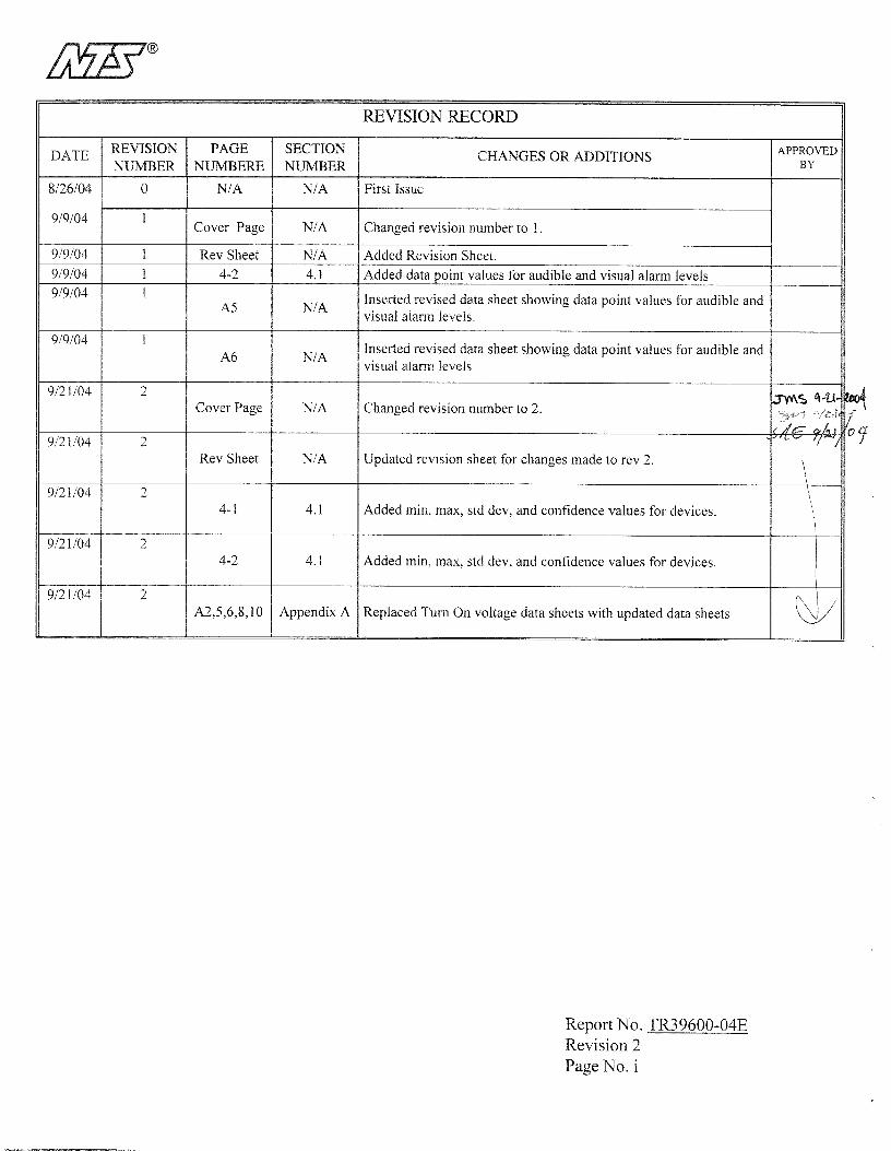
n TABLE OF CONTENTS
SECTION PAGE NO
1.0 PROGRAM SCOPE 1-1
2.0 APPLICABLE REFERENCE DOCUMENTS 2-1
3.0 DESCRIPTION OF EQUIPMENT 3-1
4.0 ELECTRICAL TESTING 4-1 to 4-2
5.0 TEST EQUIPMENT 5-1 to 5-2
APPENDIX A DATA REPORT A-1 to A-14
APPENDIX B TEST SET-UP DRAWING B-1 to B-2
Report No. TR39600-04E Revision 2 Page No. ii

n 1.0 PROGRAM SCOPE
The purpose of this Test Report is to present the methods and results of electrical tests on equipment
identified within Section 3.0 of this Test Report, in accordance with Consolidated Edison Purchase Order
No. 434643. The purpose of this program was to evaluate and compare the different devices.
The items described in Section 3.0 were supplied by Consolidated Edison.
All work conducted for this program was performed in accordance with the requirements of NTS Corporate
Quality Policy Manual, Revision 2, dated April 30, 2003.
Report No. TR39600-04E Revision 2 Page No. 1-1
n 2.0 APPLICABLE REFERENCE DOCUMENTS
2.1 Consolidated Edison. Purchase Order No. 434643, dated 07/22/04.
2.2 NTS Quote No. B-0604E-4571-3, dated 7/08/2004.
2.3 NTS Corporate Quality Policy Manual, Revision 2, dated April 30, 2003.
2.4 Consolidated Edison Test Protocol for Low Voltage Detectors.
Report No. TR39600-04E Revision 2 Page No. 2-1
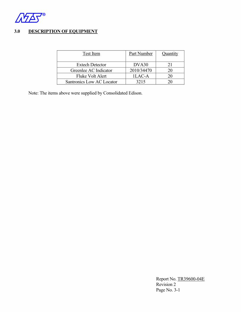
n 3.0 DESCRIPTION OF EQUIPMENT
Test Item Part Number Quantity
Extech Detector DVA30 21 Greenlee AC Indicator 2010/34470 20
Fluke Volt Alert 1LAC-A 20 Santronics Low AC Locator 3215 20
Note: The items above were supplied by Consolidated Edison.
Report No. TR39600-04E Revision 2 Page No. 3-1
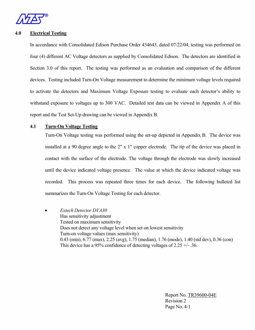
n 4.0 Electrical Testing
In accordance with Consolidated Edison Purchase Order 434643, dated 07/22/04, testing was performed on
four (4) different AC Voltage detectors as supplied by Consolidated Edison. The detectors are identified in
Section 3.0 of this report. The testing was performed as an evaluation and comparison of the different
devices. Testing included Turn-On Voltage measurement to determine the minimum voltage levels required
to activate the detectors and Maximum Voltage Exposure testing to evaluate each detector’s ability to
withstand exposure to voltages up to 300 VAC. Detailed test data can be viewed in Appendix A of this
report and the Test Set-Up drawing can be viewed in Appendix B.
4.1 Turn-On Voltage Testing
Turn-On Voltage testing was performed using the set-up depicted in Appendix B. The device was
installed at a 90 degree angle to the 2" x 1" copper electrode. The tip of the device was placed in
contact with the surface of the electrode. The voltage through the electrode was slowly increased
until the device indicated voltage presence. The value at which the device indicated voltage was
recorded. This process was repeated three times for each device. The following bulleted list
summarizes the Turn-On Voltage Testing for each detector.
• Extech Detector DVA30 Has sensitivity adjustment Tested on maximum sensitivity Does not detect any voltage level when set on lowest sensitivity Turn-on voltage values (max sensitivity) 0.43 (min), 6.77 (max), 2.25 (avg), 1.75 (median), 1.76 (mode), 1.40 (std dev), 0.36 (con) This device has a 95% confidence of detecting voltages of 2.25 +/- .36.
Report No. TR39600-04E Revision 2 Page No. 4-1

n 4.0 Electrical Testing (continued)
4.1 Turn-On Voltage Testing (continued)
• Greenlee AC Indicator Has Sensitivity Adjustment Provides audible and visual alarm indication Tested on maximum and minimum sensitivities Audible Alarm Turn-on Voltage values (max sensitivity) 2.6 (min), 5.4 (max), 3.95 (avg), 3.65 (median), 3.6 (mode), 0.7 (std dev), 0.18 (con) This device has a 95% confidence of audibly detecting voltages of 3.95 +/- .18 when set to the maximum sensitivity. Turn-on Voltage values (min sensitivity) 44.3 (min), 72.7 (max), 55.21 (avg), 54.35 (median), 53.8 (mode), 4.35 (std dev), 1.10 (con) This device has a 95% confidence of audibly detecting voltages of 55.21 +/- 1.10 when set to the minimum sensitivity. Visual Illumination Alarm Turn-on Voltage values (max sensitivity) 4.2 (min), 12.5 (max), 8.02 (avg), 7.85 (median), 7.5 (mode), 2.09 (std dev), 0.53 (con) This device has a 95% confidence of visually detecting voltages of 8.02 +/- .53 when set to the maximum sensitivity. Turn-on Voltage values (min sensitivity) 100.6 (min), 129.2 (max), 114.5 (avg), 114.8 (median), 116.8 (mode), 6.52 (std dev), 1.65 (con). This device has a 95% confidence of visually detecting voltages of 114.5 +/- .1.65 when set to the maximum sensitivity.
• Fluke Volt Alert 1LCAC-A No sensitivity adjustment. Turn-on Voltage values 12.5 (min), 14.93 (max), 13.74 (avg), 13.79 (median), 14.09 (mode), 0.70 (std dev), 0.18 (con) This device has a 95% confidence of detecting voltages of 13.74 +/- .18.
• Santronics Low AC Indicator No Sensitivity Adjustment Turn-on Voltage values 11.02 (min), 15.42 (max), 14.61 (avg), 13.60 (median), 12.81 (mode), 1.14 (std dev), 0.28 (con) This device has a 95% confidence of detecting voltages of 14.61 +/- .28.
Report No. TR39600-04E Revision 2 Page No. 4-2
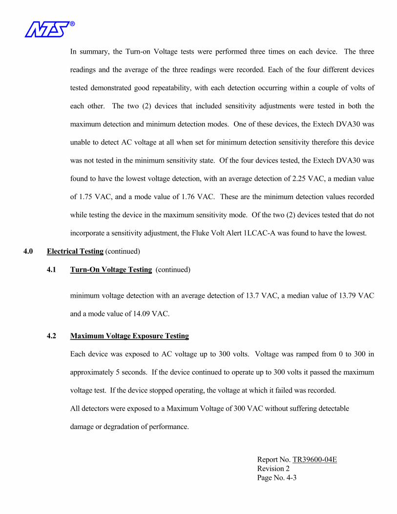
n In summary, the Turn-on Voltage tests were performed three times on each device. The three
readings and the average of the three readings were recorded. Each of the four different devices
tested demonstrated good repeatability, with each detection occurring within a couple of volts of
each other. The two (2) devices that included sensitivity adjustments were tested in both the
maximum detection and minimum detection modes. One of these devices, the Extech DVA30 was
unable to detect AC voltage at all when set for minimum detection sensitivity therefore this device
was not tested in the minimum sensitivity state. Of the four devices tested, the Extech DVA30 was
found to have the lowest voltage detection, with an average detection of 2.25 VAC, a median value
of 1.75 VAC, and a mode value of 1.76 VAC. These are the minimum detection values recorded
while testing the device in the maximum sensitivity mode. Of the two (2) devices tested that do not
incorporate a sensitivity adjustment, the Fluke Volt Alert 1LCAC-A was found to have the lowest.
4.0 Electrical Testing (continued)
4.1 Turn-On Voltage Testing (continued)
minimum voltage detection with an average detection of 13.7 VAC, a median value of 13.79 VAC
and a mode value of 14.09 VAC.
4.2 Maximum Voltage Exposure Testing
Each device was exposed to AC voltage up to 300 volts. Voltage was ramped from 0 to 300 in
approximately 5 seconds. If the device continued to operate up to 300 volts it passed the maximum
voltage test. If the device stopped operating, the voltage at which it failed was recorded.
All detectors were exposed to a Maximum Voltage of 300 VAC without suffering detectable
damage or degradation of performance.
Report No. TR39600-04E Revision 2 Page No. 4-3

n 5.0 TEST EQUIPMENT
All test equipment used for this program had calibration certification traceable to the National Institute of
Standards and Technology (NIST). A list of all equipment used during this program is included on the
following page.
Report No. TR39600-04E Revision 2 Page No. 5-1
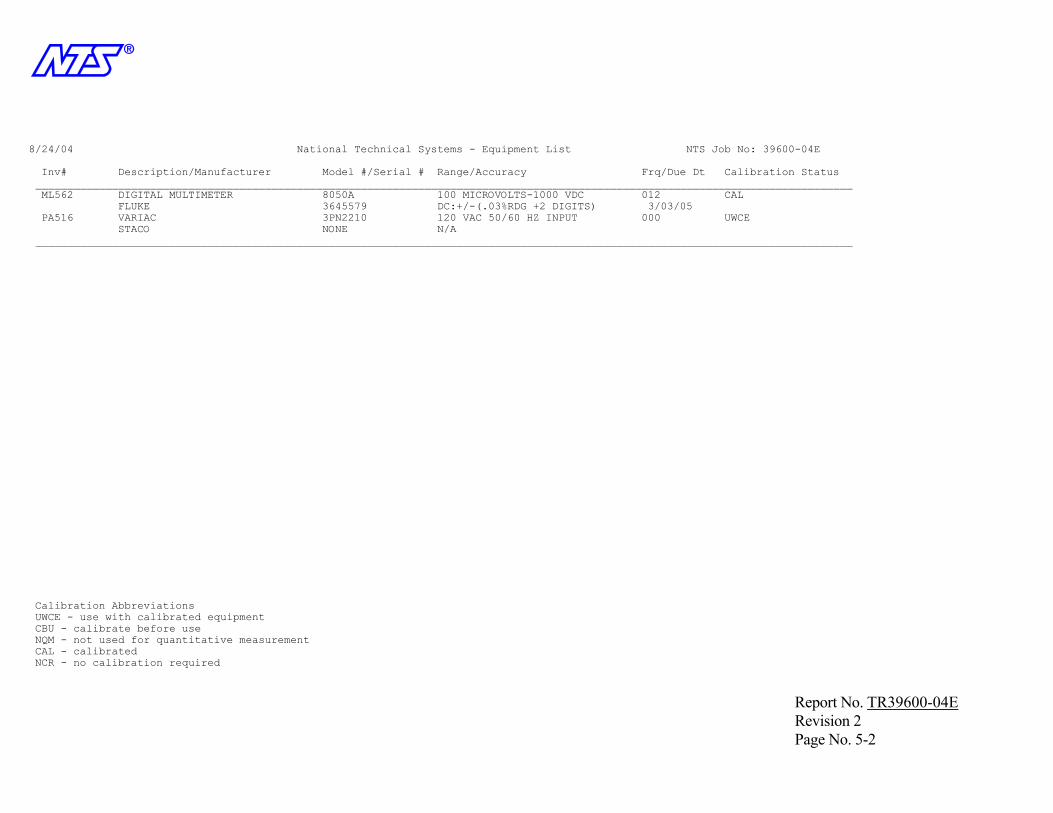
n
8/24/04 National Technical Systems - Equipment List NTS Job No: 39600-04E Inv# Description/Manufacturer Model #/Serial # Range/Accuracy Frq/Due Dt Calibration Status ________________________________________________________________________________________________________________________________ ML562 DIGITAL MULTIMETER 8050A 100 MICROVOLTS-1000 VDC 012 CAL FLUKE 3645579 DC:+/-(.03%RDG +2 DIGITS) 3/03/05 PA516 VARIAC 3PN2210 120 VAC 50/60 HZ INPUT 000 UWCE STACO NONE N/A ________________________________________________________________________________________________________________________________ Calibration Abbreviations UWCE - use with calibrated equipment CBU - calibrate before use NQM - not used for quantitative measurement CAL - calibrated NCR - no calibration required
Report No. TR39600-04E Revision 2 Page No. 5-2

n
APPENDIX A
DATA REPORT
Report No. TR39600-04E Revision 2 Appendix A Page No. A-1
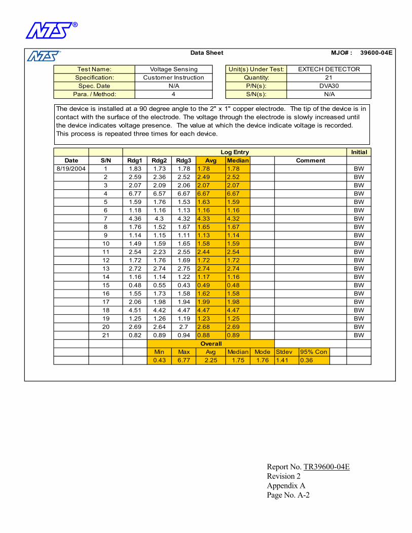
n
0.43 6.77 2.25 1.75 1.76
OverallMedian
21 BW
Min Max Avg
0.89
Stdev
19 BW20 BW2.69 2.64 2.7 2.68
BW18 BW4.51 4.42 4.47 4.47 4.47
1.5817 2.06 1.98
15 BW16 BW1.55 1.73 1.58 1.62
BW14 BW1.16 1.14 1.22 1.17 1.16
1.7213 2.742.75 2.74
11 BW12 BW1.72 1.76 1.69 1.72
10 BW1.49 1.59 1.65 1.58 1.599 BW
7 BW8 BW1.76 1.52 1.67 1.65
6 BW1.18 1.16 1.13 1.16 1.16BW
BW4 BW6.77 6.57 6.67 6.67 6.67
BW2 BW2.59 2.36 2.52 2.49 2.52
S/N Rdg1 Rdg2 Rdg3
MJO# :
S/N(s):
2.07
Log Entry InitialCommentAvg Median
Para. / Method:
3
5
8/19/2004 1Date
Voltage Sensing Unit(s) Under Test:
N/A
21P/N(s): DVA30
39600-04E
4
Data Sheet
EXTECH DETECTORSpecification: Customer Instruction
N/AQuantity:
Spec. Date
Test Name:
1.83 1.73 1.78 1.78 1.78
2.07 2.09 2.06 2.07
4.32
1.59 1.76 1.53 1.63 1.59
4.36 4.3 4.32 4.33
2.542.44
1.671.14 1.15 1.11 1.13 1.14
2.54 2.23 2.55
0.48 0.55
2.72 2.74
0.43 0.49
1.25
1.94 1.99 1.98
0.48
2.690.82 0.89 0.94 0.88
1.25 1.26 1.19 1.23
Mode1.41
95% Con0.36
The device is installed at a 90 degree angle to the 2" x 1" copper electrode. The tip of the device is in contact with the surface of the electrode. The voltage through the electrode is slowly increased until the device indicates voltage presence. The value at which the device indicate voltage is recorded. This process is repeated three times for each device.
Report No. TR39600-04E Revision 2 Appendix A Page No. A-2
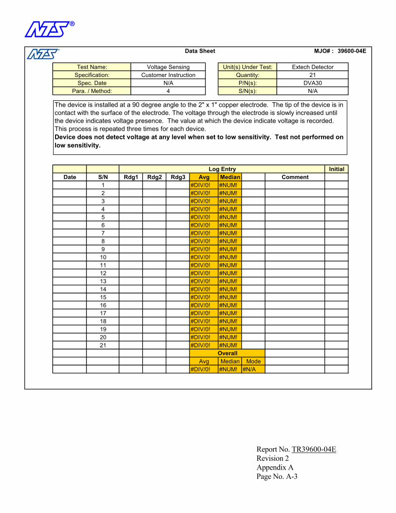
n
#DIV/0! #NUM! #N/AMedian Mode
Overall
#DIV/0!#NUM!
#DIV/0!
#DIV/0!
#NUM!
#DIV/0! #NUM!
#NUM!
#DIV/0! #NUM!
#DIV/0!
#NUM!#DIV/0!
#NUM!
#DIV/0!
#NUM!
#DIV/0! #NUM!
#DIV/0! #NUM!
39600-04E
4
Data Sheet
Extech DetectorSpecification: Customer Instruction
N/AQuantity:
Spec. Date
Test Name: Voltage Sensing Unit(s) Under Test:
N/A
21P/N(s): DVA30
Para. / Method:
3
5
1Date
MJO# :
S/N(s):
#NUM!
Log Entry InitialCommentAvg MedianS/N Rdg1 Rdg2 Rdg3
2 #DIV/0! #NUM!
4 #DIV/0! #NUM!
6 #DIV/0! #NUM!78 #DIV/0!9
10 #DIV/0! #NUM!1112 #DIV/0! #NUM!13 #NUM!#DIV/0!14 #DIV/0! #NUM!1516 #DIV/0! #NUM!1718 #DIV/0! #NUM!1920 #DIV/0!21
Avg
#NUM!
The device is installed at a 90 degree angle to the 2" x 1" copper electrode. The tip of the device is in contact with the surface of the electrode. The voltage through the electrode is slowly increased until the device indicates voltage presence. The value at which the device indicate voltage is recorded. This process is repeated three times for each device.Device does not detect voltage at any level when set to low sensitivity. Test not performed on low sensitivity.
Report No. TR39600-04E Revision 2 Appendix A Page No. A-3

n
302.9303.3 #NUM!Overall
#NUM!#NUM!
#DIV/0! 302.90#DIV/0! 300.60
#NUM!#NUM!#NUM!#NUM!
#NUM!#NUM!#NUM!#NUM!
#NUM!#NUM!#NUM!#NUM!
#NUM!#NUM!#NUM!#NUM!
Median Min
#NUM!
302.6 302.4 303.3
302.8 302.4 301.5300.1 302.8
300.6 300.2 302.9
303.2 301.7302.3 303.2 302.4
303.2
302.6302.5 301.5 302.4
301.8 302.7 302.5302.9 301.7 301.1
302.3 300.3 302.9303.2 303.5 303
300 301.4 302.3302.1 303.4 300.2
302.2 302.6 301.9300.7 302.8 303.4
303.8300.1300.2303 301.4 300
21 BW
Avg
300.2
19 BW20 BW301.23
BW18 BW302.63 #DIV/0! 302.40
#DIV/0! 301.8017
300.3 301.8 302.6303.5
15 BW16 BW301.57
BW14 BW302.23 #DIV/0! 302.40
#DIV/0! 302.1013 #DIV/0! 302.40302.13
301.9 302.111 BW12 BW302.20
10 BW302.33 #DIV/0! 302.50
303.209 BW301.1 302.3 301.1
7 BW8 BW303.23
6 BW301.90 #DIV/0! 302.10 #NUM!
302.80BW
301.40BW
4 BW302.30 #DIV/0!
Median Max
BW2 BW301.47 #DIV/0!
S/NRdg1 Min Sensitivity
Rdg2 Min Sensitivity
Rdg3 Min Sensitivity
Rdg1 Max Sensitivity
Rdg2 Max Sensitivity
Rdg3 Max Sensitivity
MJO# :
S/N(s):
#DIV/0!
Log Entry Initial
CommentAvg Max Avg Min
Para. / Method:
3
5
8/19/2004 1Date
Max Voltage Exposure Unit(s) Under Test:21
P/N(s): DVA30
39600-04E
4
Data Sheet
Extech DetectorSpecification: Customer Instruction
N/AQuantity:
Spec. Date
Test Name:
302.20
301.37 #DIV/0! 300.20
302.23
#DIV/0! 302.30
301.23 #DIV/0! 301.40
301.83
#DIV/0!301.90
#DIV/0!
301.70
301.50 #DIV/0! 301.10
302.03
#DIV/0! 302.60
302.80 #DIV/0! 303.20
#DIV/0! 302.80
302.77
302.13
302.30 300.2Median Mode
302.05
Device is exposed to AC voltage up to 300 volts. Voltage is ramped from 0 to 300 in approximately 5 seconds. If the device continues to operate up to 300 volts it shall have passed the maximum voltage test. If the device stops operating, the voltage at which it fails shall be recorded.
These units do not sense voltage with the dial on the minimum setting. High voltage test not performed with device set at minimum sensitivity.
Report No. TR39600-04E Revision 2 Appendix A Page No. A-4
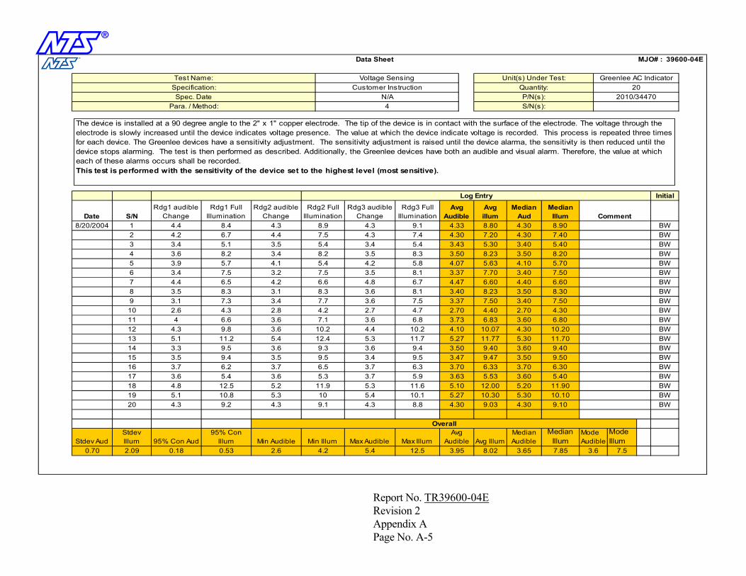
n
7.85
Mode Audible
Mode Illum
3.6 7.5
Median Illum
10.109.10
Median Audible
4.2 5.4 12.5 3.95
10 5.4 10.1 5.27
9.5 3.47
10.30 5.30
5.9 3.63 5.53 3.60
9.47 3.509.5 3.4
12.4 5.3
3.60
7.7 3.6 7.5 3.37 7.50 3.40
7.1 3.6 6.8
4.8 6.7 4.47
6.833.73
8.23
3.43
6.60 4.40
5.4 4.2 5.8 4.07 5.63 4.10
6.6
3.40
8.9 4.3 9.1 4.33 8.80 4.30
5.4 3.4 5.4
39600-04E
4
Data Sheet
Greenlee AC IndicatorSpecification: Customer Instruction
N/AQuantity:
Spec. Date
Test Name: Voltage Sensing Unit(s) Under Test:20
P/N(s): 2010/34470Para. / Method:
3
5
8/20/2004 1Date
MJO# :
S/N(s):
5.30
Log Entry Initial
CommentAvg
AudibleAvg illumS/N
Rdg2 Full Illumination
Rdg3 audible Change
Rdg3 Full Illumination
Rdg1 audible Change
Rdg1 Full Illumination
Rdg2 audible Change
Median Aud
BW2 BW7.5 4.3 7.4 4.30 7.20 4.30
BW4 BW8.2 3.5 8.3 3.50 8.23 3.50
BW6 BW7.5 3.5 8.1 3.37 7.70 3.40 7.507 BW8 BW8.3 3.6 8.1 3.40 3.509 BW3.1 7.3 3.410 BW4.2 2.7 4.7 2.70 4.40 2.7011 BW12 BW10.2 4.4 10.2 4.10 10.07 4.3013 11.77 5.3011.7 5.27
4.3 9.8BW
14 BW9.3 3.6 9.4 3.50 9.40 3.6015 BW16 BW6.5 3.7 6.3 3.70 6.33 3.7017 5.3 3.7
3.7 6.2 3.73.6 BW
18 BW11.9 5.3 11.6 5.10 12.00 5.2019 BW20 BW9.1 4.3 8.8 4.30
Max Audible Max IllumAvg
Audible0.70 2.09
Stdev AudStdev Illum Min Illum
4.38.44.44.2 6.7 4.43.4 5.1 3.53.6 8.2 3.43.9 5.7 4.13.4 7.5 3.24.4 6.5 4.23.5 8.3 3.1
2.6 4.3 2.84 6.6 3.6
3.5
3.65.1 11.2 5.4
4.3 9.2 4.3
5.4 3.64.8 12.5 5.2
Median Illum8.90
5.1 10.8 5.3
3.3 9.5 3.63.5 9.4
7.405.408.205.70
6.608.307.504.306.8010.2011.709.409.506.305.4011.90
9.03 4.30
95% Con Aud0.18
95% Con Illum0.53
Min Audible2.6
Overall
8.02 3.65Avg Illum
The device is installed at a 90 degree angle to the 2" x 1" copper electrode. The tip of the device is in contact with the surface of the electrode. The voltage through the electrode is slowly increased until the device indicates voltage presence. The value at which the device indicate voltage is recorded. This process is repeated three times for each device. The Greenlee devices have a sensitivity adjustment. The sensitivity adjustment is raised until the device alarma, the sensitivity is then reduced until the device stops alarming. The test is then performed as described. Additionally, the Greenlee devices have both an audible and visual alarm. Therefore, the value at which each of these alarms occurs shall be recorded.This test is performed with the sensitivity of the device set to the highest level (most sensitive).
Report No. TR39600-04E Revision 2 Appendix A Page No. A-5
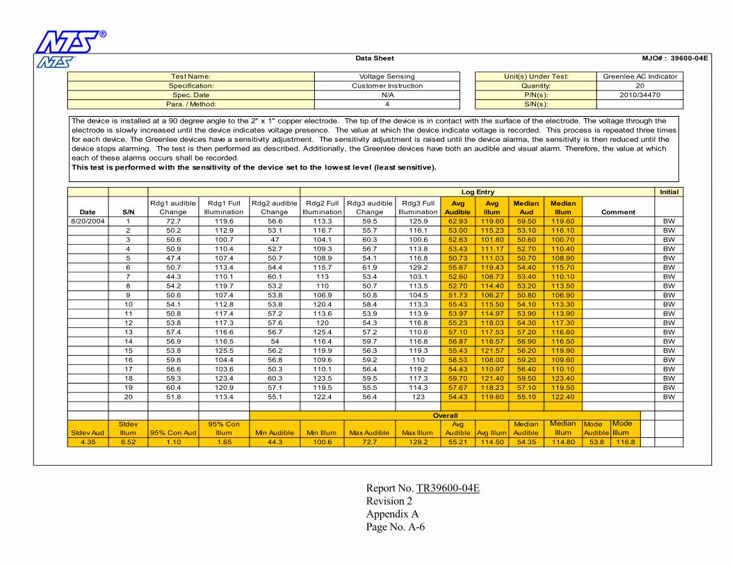
n
100.6
Mode Audible
Mode Illum
53.8 116.8
Median Illum
114.80114.50 54.35Avg Illum
Median Audible
118.23 57.10
1.10
95% Con Illum1.65
Min Audible44.3
119.90109.60110.10123.40
113.90117.30116.60116.50
110.10113.50106.90113.30
116.10100.70110.40108.90
Median Illum
119.60
60.4 120.9 57.1
56.9 116.5 5453.8 125.5
51.8 113.4 55.1
103.6 50.359.3 123.4 60.3
56.2
57.657.4 116.6 56.7
54.1 112.8 53.850.8 117.4 57.2
44.3 110.1 60.154.2 119.7 53.2
47.4 107.4 50.750.7 113.4 54.4
50.6 100.7 4750.9 110.4 52.7
56.6119.672.750.2 112.9 53.1
4.35 6.52Stdev Aud
Stdev Illum Min Illum Max Audible Max Illum
Avg Audible95% Con Aud
19 BW20 BW122.4 56.4 123 54.43
BW18 BW123.5 59.5 117.3 59.70 121.40 59.50
59.6 104.4 56.856.617 110.1 56.4
15 BW16 BW109.6 59.2 110 58.53
BW14 BW116.4 59.7 116.8 56.87 116.57 56.90
118.03 54.3013 117.53 57.20110.6 57.10
53.8 117.311 BW12 BW120 54.3 116.8 55.23
10 BW120.4 58.4 113.3 55.43 115.50 54.10
53.209 BW50.6 107.4 53.8
7 BW8 BW110 50.7 113.5 52.70
6 BW115.7 61.9 129.2 55.67 119.43 54.40 115.70
52.70BW
53.10BW
4 BW109.3 56.7 113.8 53.43 111.17
Median Aud
BW2 BW116.7 55.7 116.1 53.00 115.23
S/NRdg2 Full
IlluminationRdg3 audible
ChangeRdg3 Full
IlluminationRdg1 audible
ChangeRdg1 Full
IlluminationRdg2 audible
Change
MJO# :
S/N(s):
101.80
Log Entry Initial
CommentAvg
AudibleAvg illum
Para. / Method:
3
5
8/20/2004 1Date
Voltage Sensing Unit(s) Under Test:20
P/N(s): 2010/34470
39600-04E
4
Data Sheet
Greenlee AC IndicatorSpecification: Customer Instruction
N/AQuantity:
Spec. Date
Test Name:
50.60
113.3 59.5 125.9 62.93 119.60 59.50
104.1 60.3 100.6 52.63
108.73 53.40
108.9 54.1 116.8 50.73 111.03 50.70
113 53.4 103.1 52.60
114.9753.97
114.40
53.90
106.9 50.8 104.5 51.73 106.27 50.80
113.6 53.9 113.9
119.9 56.3
125.4 57.2
110.97 56.40
121.57 56.20108.00 59.20
119.3 55.43
119.2 54.43
72.7 129.2 55.21
Overall
119.5 55.5 114.3 57.67 119.50122.40119.60 55.10
The device is installed at a 90 degree angle to the 2" x 1" copper electrode. The tip of the device is in contact with the surface of the electrode. The voltage through the electrode is slowly increased until the device indicates voltage presence. The value at which the device indicate voltage is recorded. This process is repeated three times for each device. The Greenlee devices have a sensitivity adjustment. The sensitivity adjustment is raised until the device alarma, the sensitivity is then reduced until the device stops alarming. The test is then performed as described. Additionally, the Greenlee devices have both an audible and visual alarm. Therefore, the value at which each of these alarms occurs shall be recorded.This test is performed with the sensitivity of the device set to the lowest level (least sensitive).
Report No. TR39600-04E Revision 2 Appendix A Page No. A-6
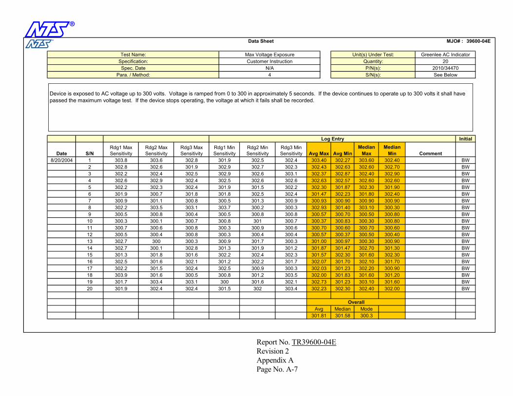
n
301.81 301.58 300.3Median Mode
300 301.6 302.1 302.73
302.3 301.57
301.23 303.10
300.3 302.03 301.23 302.20
302.30 301.60302.2 302.4
300.9 301.7
300.70
300.5 300.8 300.8 300.57 300.70 300.50
300.3 300.9 300.6
301.3 300.9 300.93
300.60300.70
301.40
302.37
300.90 300.90
301.9 301.5 302.2 302.30 301.87 302.30
300.5
302.40
301.9 302.5 302.4 303.40 302.27 303.60
302.9 302.6 303.1
39600-04E
4
Data Sheet
Greenlee AC IndicatorSpecification: Customer Instruction
N/AQuantity:
Spec. Date
Test Name: Max Voltage Exposure Unit(s) Under Test:
See Below
20P/N(s): 2010/34470
Para. / Method:
3
5
8/20/2004 1Date
MJO# :
S/N(s):
302.87
Log Entry Initial
CommentAvg Max Avg MinS/NRdg1 Min Sensitivity
Rdg2 Min Sensitivity
Rdg3 Min Sensitivity
Rdg1 Max Sensitivity
Rdg2 Max Sensitivity
Rdg3 Max Sensitivity
Median Max
BW2 BW302.9 302.7 302.3 302.43 302.63 302.60
BW4 BW302.5 302.6 302.6 302.63 302.57 302.60
BW6 BW301.8 302.5 302.4 301.47 302.23 301.80 302.407 BW8 BW303.7 300.2 300.3 302.93 303.109 BW300.5 300.8 300.410 BW300.8 301 300.7 300.37 300.83 300.3011 BW12 BW300.3 300.4 300.4 300.57 300.37 300.5013 300.97 300.30300.3 301.00
300.5 300.4BW
14 BW301.3 301.9 301.2 301.87 301.47 302.7015 BW16 BW301.2 302.2 301.7 302.07 301.70 302.1017 302.5 300.9
302.5 301.6 302.1302.2 BW
18 BW300.8 301.2 303.5 302.00 301.83 301.6019 BW20 BW301.5 302 303.4 302.23
Avg
302.8303.6303.8302.8 302.6 301.9302.2 302.4 302.5302.6 302.9 302.4302.2 302.3 302.4301.9 300.7 301.8300.9 301.1 300.8302.2 303.5 303.1
300.3 300.1 300.7300.7 300.6 300.8
301.6
300.8302.7 300 300.3
301.9 302.4 302.4
301.5 302.4303.9 301.6 300.5
Median Min
302.40
301.7 303.4 303.1
302.7 300.1 302.8301.3 301.8
302.70302.90302.60301.90
300.90300.30300.80300.80300.60300.40300.90301.30302.30301.70300.90301.20
Overall
301.60302.00302.30 302.40
Device is exposed to AC voltage up to 300 volts. Voltage is ramped from 0 to 300 in approximately 5 seconds. If the device continues to operate up to 300 volts it shall have passed the maximum voltage test. If the device stops operating, the voltage at which it fails shall be recorded.
Report No. TR39600-04E Revision 2 Appendix A Page No. A-7
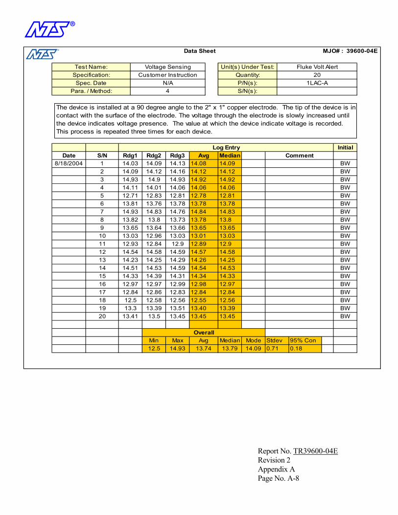
n
12.5 14.93 13.74 13.79 14.09
OverallMedianMin Max Avg Stdev
19 BW20 BW13.41 13.5 13.45 13.45
BW18 BW12.5 12.58 12.56 12.55 12.56
12.9717 12.84 12.86
15 BW16 BW12.97 12.97 12.99 12.98
BW14 BW14.51 14.53 14.59 14.54 14.53
14.5813 14.2514.29 14.26
11 BW12 BW14.54 14.58 14.59 14.57
10 BW13.03 12.96 13.03 13.01 13.039 BW
7 BW8 BW13.82 13.8 13.73 13.78
6 BW13.81 13.76 13.78 13.78 13.78BW
BW4 BW14.11 14.01 14.06 14.06 14.06
BW2 BW14.09 14.12 14.16 14.12 14.12
S/N Rdg1 Rdg2 Rdg3
MJO# :
S/N(s):
14.92
Log Entry InitialCommentAvg Median
Para. / Method:
3
5
8/18/2004 1Date
Voltage Sensing Unit(s) Under Test:20
P/N(s): 1LAC-A
39600-04E
4
Data Sheet
Fluke Volt AlertSpecification: Customer Instruction
N/AQuantity:
Spec. Date
Test Name:
14.03 14.09 14.13 14.08 14.09
14,93 14.9 14.93 14.92
14.83
12.71 12.83 12.81 12.78 12.81
14.93 14.83 14.76 14.84
12.912.89
13.813.65 13.64 13.66 13.65 13.65
12.93 12.84 12.9
14.33 14.39
14.23 14.25
14.31 14.34
13.39
12.83 12.84 12.84
14.33
13.4513.3 13.39 13.51 13.40
Mode 95% Con0.71 0.18
The device is installed at a 90 degree angle to the 2" x 1" copper electrode. The tip of the device is incontact with the surface of the electrode. The voltage through the electrode is slowly increased until the device indicates voltage presence. The value at which the device indicate voltage is recorded. This process is repeated three times for each device.
Report No. TR39600-04E Revision 2 Appendix A Page No. A-8
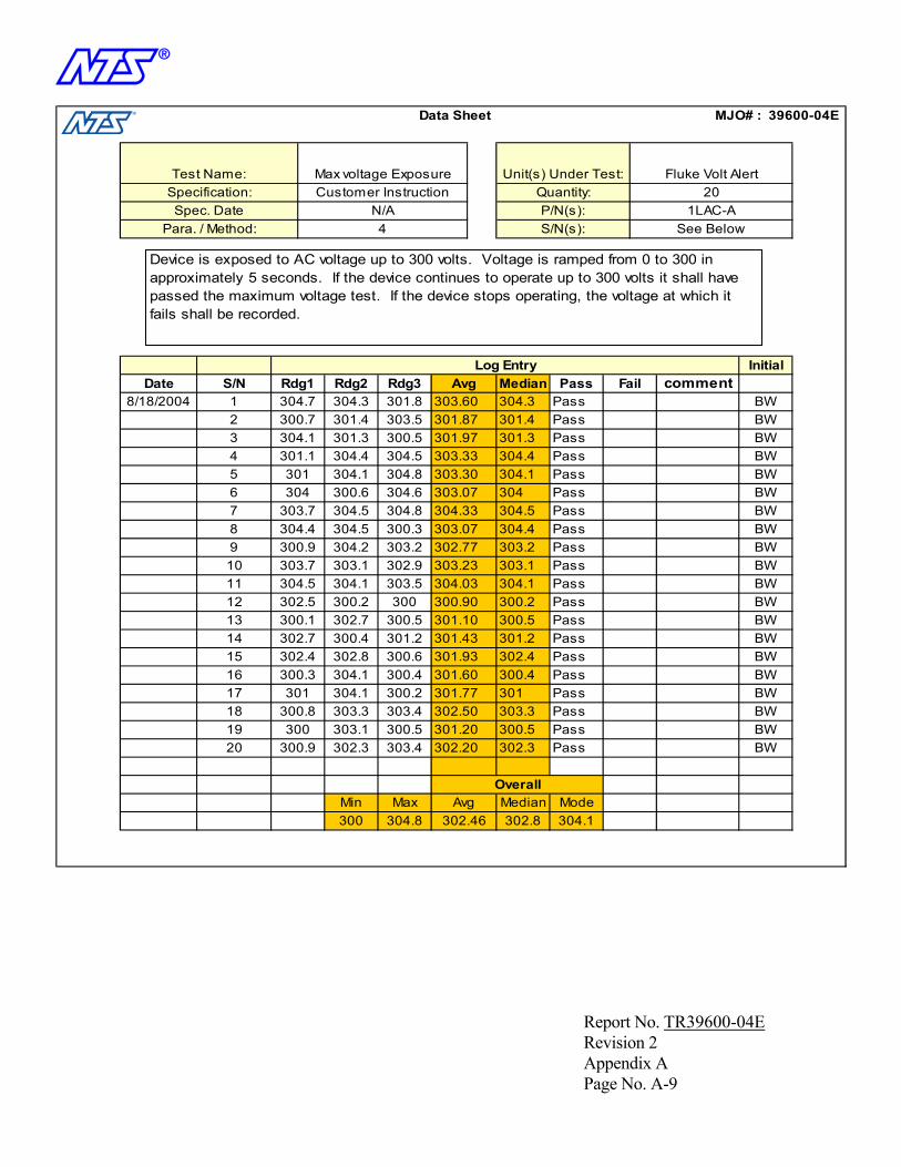
n
300 304.8 302.46 302.8 304.1Median Mode
Overall
300 303.1 300.5 301.20302.3 Pass
301.93
300.5 Pass
300.2 301.77 301 Pass
302.4 Pass300.4
304.5 304.1 303.5
302.4 302.8
300.1 302.7
300.6
304.1304.03
304.4
Pass
302.77 303.2 Pass
301.97
304.5 Pass
301 304.1 304.8 303.30 304.1 Pass
303.7
Pass
304.7 304.3 301.8 303.60 304.3 Pass
304.1 301.3 300.5
39600-04E
4
Data Sheet
Fluke Volt AlertSpecification: Customer Instruction
N/AQuantity:
Spec. Date
Test Name: Max voltage Exposure Unit(s) Under Test:
See Below
20P/N(s): 1LAC-A
3
5
8/18/2004 1Date S/N
MJO# :
S/N(s):
301.3
Log Entry InitialAvg Median
Para. / Method:
Rdg1 Rdg2 Rdg3 PassBW
2 BW300.7 301.4 303.5 301.87 301.4 PassBW
4 BW301.1 304.4 304.5 303.33 304.4 PassBW
6 BW304 300.6 304.6 303.07 304 Pass7 304.5 304.8 304.33 BW8 BW304.4 304.5 300.3 303.07 Pass9 BW300.9 304.2 303.210 BW303.7 303.1 302.9 303.23 303.1 Pass11 BW12 BW302.5 300.2 300 300.90 300.2 Pass13 300.5 Pass300.5 301.10 BW14 BW302.7 300.4 301.2 301.43 301.2 Pass15 BW16 BW300.3 304.1 300.4 301.60 Pass17 301 304.1 BW18 BW300.8 303.3 303.4 302.50 303.3 Pass19 BW20 BW300.9 302.3 303.4 302.20
Min Max Avg
Fail comment
Device is exposed to AC voltage up to 300 volts. Voltage is ramped from 0 to 300 in approximately 5 seconds. If the device continues to operate up to 300 volts it shall have passed the maximum voltage test. If the device stops operating, the voltage at which it fails shall be recorded.
Report No. TR39600-04E Revision 2 Appendix A Page No. A-9

n
Stdev1.14
95% Conf0.2911.02 15.42 13.61 13.67 12.81
Median Mode
14.58 14.47 14.61 14.5514.64
13.74 13.67
14.58
14.57 14.67 14.67
13.6613.66 13.61
15.26 15.2
13.64 13.74 13.71 13.70 13.71
11.99 13.04 12.8
11.19 11.3 11.17
12.8012.61
14.46
12.86
11.19
13.29 13.42 13.08 13.26 13.29
11.02
13.27 13.16 14.38 13.60 13.27
12.85 12.78 12.95
39600-04
4
Data Sheet
Santronics Low AC LocatorSpecification: Customer Instruction
N/AQuantity:
Spec. Date
Test Name: Voltage Sensing Unit(s) Under Test:
See Below
20P/N(s): 3215
Para. / Method:
3
5
8/17/2004 1Date
MJO# :
S/N(s):
12.85
Log Entry InitialCommentAvg MedianS/N Rdg1 Rdg2 Rdg3
BW2 BW14.43 14.44 14.52 14.46 14.44
BW4 BW12.81 12.62 12.83 12.75 12.81
BW6 BW12.36 12.65 12.56 12.52 12.567 BW8 BW14.46 14.13 14.51 14.379 BW10 BW13.75 13.67 13.51 13.64 13.6711 BW12 BW11.87 11.77 11.47 11.70 11.7713 15.2615.42 15.29 BW14 BW12.89 12.96 12.81 12.89 12.8915 BW16 BW14.62 15.14 14.57 14.78 14.6217 14.67 14.77 BW18 BW15.29 15.27 15.24 15.27 15.2719 BW20 BW14.66 14.64 14.24 14.51
Min Max AvgOverall
E
The device is installed at a 90 degree angle to the 2" x 1" copper electrode. The tip of the device is in contact with the surface of the electrode. The voltage through the electrode is slowly increased until the device indicates voltage presence. The value at which the device indicate voltage is recorded. This process is repeated three times for each device.
Report No. TR39600-04E Revision 2 Appendix A Page No. A-10
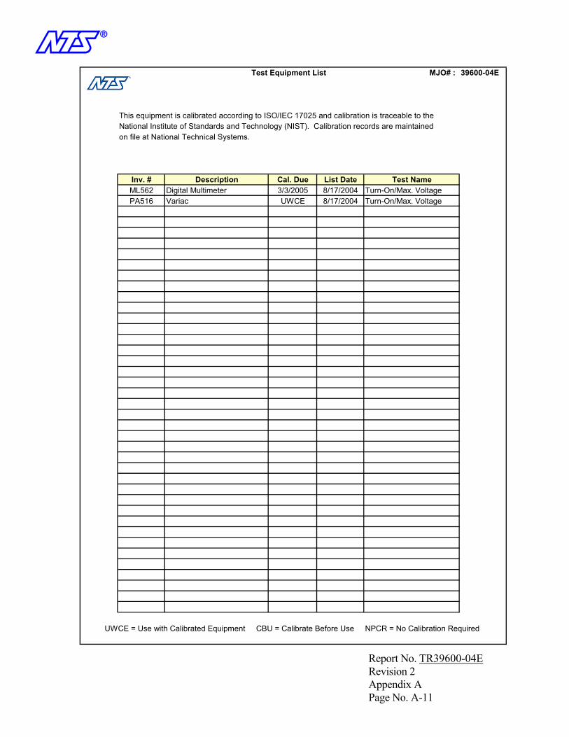
n
UWCE = Use with Calibrated Equipment CBU = Calibrate Before Use NPCR = No Calibration Required
MJO# : 39600-04E
Turn-On/Max. VoltagePA516 Variac UWCE 8/17/2004 Turn-On/Max. VoltageML562 Digital Multimeter 3/3/2005 8/17/2004Inv. # Test NameList DateCal. DueDescription
Test Equipment List
This equipment is calibrated according to ISO/IEC 17025 and calibration is traceable to the National Institute of Standards and Technology (NIST). Calibration records are maintained on file at National Technical Systems.
Report No. TR39600-04E Revision 2 Appendix A Page No. A-11
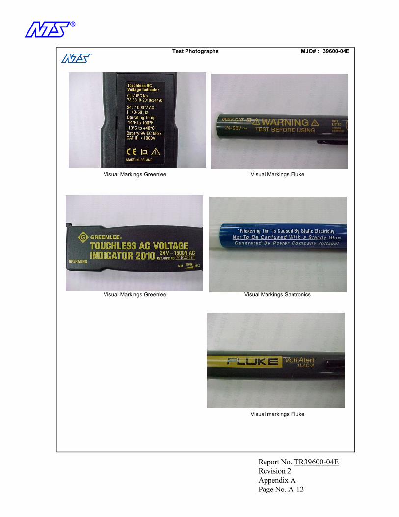
n Test Photographs MJO# : 39600-04E
Visual Markings Greenlee
Insert Pictures here, format to 3" width
Visual Markings Fluke
Visual Markings Greenlee Visual Markings Santronics
Visual markings Fluke
Report No. TR39600-04E Revision 2 Appendix A Page No. A-12
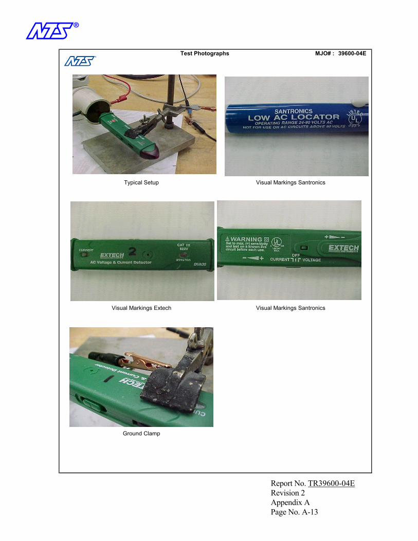
n
Ground Clamp
Visual Markings Extech Visual Markings Santronics
Typical Setup
Insert Pictures here, format to 3" width
Visual Markings Santronics
Test Photographs MJO# : 39600-04E
Report No. TR39600-04E Revision 2 Appendix A Page No. A-13

n
30
OK
13
ITEM QTY. S/N
Receiver MJO# :
Description
39600-04E
1 21 DVA30
Unit(s) Received by: S Maxwell Date: 8/17/2004
P/N
Fluke Volt Alert X2 20 2010/34470
Extech Detector XGreenlee AC Indicator X
Santronics Low AC Locator X3 204 20 3215
1LAC-A
56789101112
14151617181920212223242526272829
Report No. TR39600-04E Revision 2 Appendix A Page No. A-14

n
APPENDIX B
TEST SET-UP DRAWING
Report No. TR39600-04E Revision 2 Appendix B Page No. B-1
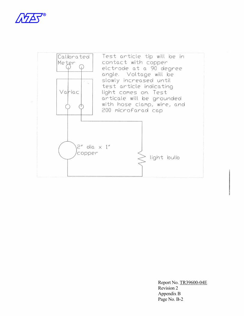
n
Report No. TR39600-04E Revision 2 Appendix B Page No. B-2

95
M: Corporate Safety Procedure 17.01
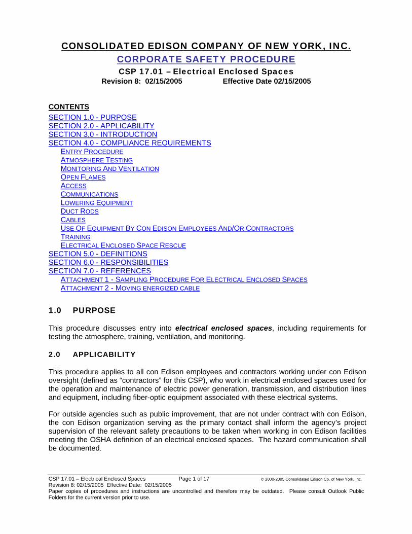
CSP 17.01 – Electrical Enclosed Spaces Page 1 of 17 © 2000-2005 Consolidated Edison Co. of New York, Inc. Revision 8: 02/15/2005 Effective Date: 02/15/2005 Paper copies of procedures and instructions are uncontrolled and therefore may be outdated. Please consult Outlook Public Folders for the current version prior to use.
CONSOLIDATED EDISON COMPANY OF NEW YORK, INC. CORPORATE SAFETY PROCEDURE CSP 17.01 – Electrical Enclosed Spaces
Revision 8: 02/15/2005 Effective Date 02/15/2005 CONTENTSSECTION 1.0 - PURPOSESECTION 2.0 - APPLICABILITYSECTION 3,0 - INTRODUCTIONSECTION 4.0 - COMPLIANCE REQUIREMENTS
ENTRY PROCEDUREATMOSPHERE TESTINGMONITORING AND VENTILATIONOPEN FLAMESACCESSCOMMUNICATIONSLOWERING EQUIPMENTDUCT RODSCABLESUSE OF EQUIPMENT BY CON EDISON EMPLOYEES AND/OR CONTRACTORSTRAININGELECTRICAL ENCLOSED SPACE RESCUE
SECTION 5.0 - DEFINITIONSSECTION 6.0 - RESPONSIBILITIESSECTION 7.0 - REFERENCES
ATTACHMENT 1 - SAMPLING PROCEDURE FOR ELECTRICAL ENCLOSED SPACES ATTACHMENT 2 - MOVING ENERGIZED CABLE
1.0 PURPOSE
This procedure discusses entry into electrical enclosed spaces, including requirements for testing the atmosphere, training, ventilation, and monitoring.
2.0 APPLICABILITY
This procedure applies to all con Edison employees and contractors working under con Edison oversight (defined as “contractors” for this CSP), who work in electrical enclosed spaces used for the operation and maintenance of electric power generation, transmission, and distribution lines and equipment, including fiber-optic equipment associated with these electrical systems.
For outside agencies such as public improvement, that are not under contract with con Edison, the con Edison organization serving as the primary contact shall inform the agency’s project supervision of the relevant safety precautions to be taken when working in con Edison facilities meeting the OSHA definition of an electrical enclosed spaces. The hazard communication shall be documented.
CSP 17.01 – Electrical Enclosed Spaces Page 2 of 17 © 2000-2005 Consolidated Edison Co. of New York, Inc. Revision 8: 02/15/2005 Effective Date: 02/15/2005 Paper copies of procedures and instructions are uncontrolled and therefore may be outdated. Please consult Outlook Public Folders for the current version prior to use.
3.0 INTRODUCTION
This document identifies the procedures for inspection, entry and work in electrical enclosed spaces. Spaces that are not designed for entry under normal operating conditions are not considered to be electrical enclosed spaces for the purposes of this procedure. In addition, spaces that are expected to contain a hazardous atmosphere are not considered to be electrical enclosed spaces. These spaces are addressed as permit-required confined spaces.
This procedure does not address practices in permit-required confined spaces, gas enclosed spaces (working spaces such as gas manholes) and similar structures not associated with electric power generation, transmission, and distribution. Entry into these spaces must be performed in accordance with applicable Corporate Safety Procedures (CSPs). Permit-required confined spaces are addressed in CSP 16.00 - Permit-Required Confined Space Program, and gas enclosed spaces are addressed in CSP 17.02 - Gas Enclosed Spaces.
4.0 COMPLIANCE REQUIREMENTS
4.1 ENTRY PROCEDURE
4.1.1 Job Briefings
The employee in charge shall conduct a job briefing with the employees involved before they start the job. The briefing shall cover: the hazards associated with the job; work procedures involved; special precautions; energy source controls; and personal protective equipment requirements. Additional briefings shall be held if significant changes, which might affect the safety of the employees, occur during the course of the work. Completion of a job briefing shall be documented.
4.1.2 Vehicular or Pedestrian Traffic
Prior to the performance of work, protection of enclosed space entry work areas shall be planned, using the con Edison Work Area Protection and Traffic Control Field Manual, to avoid vehicular and pedestrian traffic hazards.
4.1.3 Pre-Entry Inspection
4.1.3.1 Evaluation of Potential Hazards
Before an entrance cover to an enclosed space is removed, it shall be determined that removal can be done safely and if the condition of the electrical facilities contained therein is sufficient to allow unrestricted access. A qualified con Edison employee must conduct this initial inspection. The initial inspection shall include:
1) Testing for stray voltage on the frame, cover, or grating, in accordance with OJT ELE0020.
2) Checking whether the cover is above “normal”, expected temperature.
3) Gradually loosening the cover if it is fastened in place, to release any residual pressure.
CSP 17.01 – Electrical Enclosed Spaces Page 3 of 17 © 2000-2005 Consolidated Edison Co. of New York, Inc. Revision 8: 02/15/2005 Effective Date: 02/15/2005 Paper copies of procedures and instructions are uncontrolled and therefore may be outdated. Please consult Outlook Public Folders for the current version prior to use.
4) Determining whether there might be a hazardous atmosphere in the space, or whether conditions at the site could cause a hazardous atmosphere, such as an oxygen deficient or flammable atmosphere to develop within the space. This includes the oxygen level, presence of a flammable atmosphere, carbon monoxide levels, and if applicable, other toxic contaminants. Where vented manholes are present, the vent holes shall be used to test the atmosphere. If an atmosphere is potentially in the flammable range or above the upper explosive limit, if it is determined that the cover should be removed, it should be done without creating a spark.
Any conditions making it unsafe to remove the cover shall be eliminated before the cover is removed (that is, reduced to the extent that it is no longer unsafe).
4.1.3.2 Removal/Opening of the Cover
Before attempting to remove covers from subsurface structures, appropriate (manhole hooks, bars, etc.) tools shall be used to remove covers from subsurface structures. When covers are removed from electrical enclosed spaces, a railing shall promptly guard the opening with appropriate toe guards, temporary cover, or other barrier to prevent an accidental fall through the opening and to protect employees working in the space.
4.1.3.3 Burnouts or Electrical Failure
Only con Edison qualified employees shall complete the work identified in this paragraph. If evidence is present of cable or component failure, fire, smoke, explosion, or other abnormalities, additional PPE in the form of protective hood (C/S 684-0755) and goggles (C/S 689-3952) shall be worn prior to approaching the cover. Employees responding to burnouts may remove the cover if it can be done safely. After removal of the cover, the employees shall remain at a safe distance away for a period of 10 minutes in the absence of a flare-up. If a flare-up occurs, the employee shall remain at a safe distance until the burning stops. The hose of a power ventilator may be directed into the opening if the hose can be placed safely. After a burnout is cleared (burnt apart or cut), the structure shall be ventilated to remove gases and odors created by the burnout.
4.1.3.4 Con Edison Initial Entry and Visual Inspection
Once the structure is initially entered, a visual inspection shall be conducted for exposed live conductors, improperly sealed cable ends, visual burnouts, structural damage, D-Fault tags, environmental tags, and cable ends cut excessively long where the cable-end could contact the structure cover/grating or metal frame. The visual inspection shall be documented. In addition, abnormalities, such as oil or compound leaking from cable or joints, broken cable sheaths or joint sleeves, hot localized surface temperatures of cables or joints, or joints that are swollen beyond normal tolerance are presumed to lead to or to be an indication of an impending fault. EO-1184, Identifying Cable And Splice Abnormalities On Distribution Feeders, shall be followed to determine when a cable must be de-energized for work in a manhole. If a “D” Fault is noted, it must be reported and the structure shall be exited immediately. If a D-Fault tag, environmental tag, or any unsafe condition is found further steps shall only be taken with consent and advice of the control center and/or field supervisor. Cable inspections are not required for enclosed spaces where electrical equipment has not been previously tied into the system, or service boxes with no primary cable.

CSP 17.01 – Electrical Enclosed Spaces Page 4 of 17 © 2000-2005 Consolidated Edison Co. of New York, Inc. Revision 8: 02/15/2005 Effective Date: 02/15/2005 Paper copies of procedures and instructions are uncontrolled and therefore may be outdated. Please consult Outlook Public Folders for the current version prior to use.
4.1.4 Entry by Con Edison Personnel not qualified for Electrical Work, Contractors, or Public Improvement Personnel
If entry takes place immediately after the initial inspection (see Section 4.1.3.4), a follow-up inspection is not required provided that the con Edison Inspector or the contractor foreman were on location during the initial inspection by the qualified electrical worker. If entry by non-qualified personnel (i.e., con Edison employees not qualified for electrical work, contractors, and Public Improvement personnel) is not immediate but takes place within 72 hours of the initial inspection, a “follow-up inspection” shall be conducted prior to each entry. The follow-up inspection shall be conducted by a qualified person (con Edison or contractor trained by con Edison) involved in the work and include:
1) Verification that the initial inspection was performed in the specified time frame.
2) Testing for stray voltage by a qualified con Edison employee or qualified contractor.
3) Completion of atmospheric testing as outlined in Section 4.2
4) Determination that it is safe to enter the space.
5) A visual inspection for abnormalities such as faults or non-capped cable.
6) Communication of inspection results and hazards to the con Edison inspectors and the contractor foreman.
If entry is delayed past the 72 hours, the initial inspection shall be repeated per Section 4.1.3.4. Con Edison personnel not qualified for electrical work may only enter after the “follow-up” inspection is conducted by qualified personnel. Follow-up inspections shall be documented. Service boxes without primary service are exempt from the initial inspection (Section 4.1.3.4), however shall have the equivalent of the “follow-up inspection”. This section does not apply for enclosed spaces where electrical equipment has not been previously tied into the system.
4.1.5 Defective Primary and/or Secondary Cable
Where a cable in a manhole has one or more abnormalities that could lead to or that could be an indication of an impending fault, the defective cable shall be de-energized before an employee may work in the manhole. Abnormalities, such as oil or compound leaking from cables or joints, broken cable sheaths or joint sleeves, hot localized surface temperatures of cables or joints, or joints that are swollen beyond normal tolerance are presumed to lead to or be an indication of an impending fault. The latest version of EO-1184, Identifying Cable And Splice Abnormalities On Distribution Feeders, shall be followed in all cases involving D-Faults.
4.1.6 Attendants
While work is performed in an electrical enclosed space, an attendant shall be available in the immediate vicinity to render emergency assistance. The attendant shall not be distracted from the duty such as speaking on a cell phone. Occasionally, the attendant may briefly enter a manhole to provide assistance other than in an emergency. This person is not precluded from performing other duties outside the electrical enclosed space if these duties do not distract the attendant from monitoring employees within the space. Manhole attendants shall be trained in first aid, cardiopulmonary resuscitation (CPR), and rescue.

CSP 17.01 – Electrical Enclosed Spaces Page 5 of 17 © 2000-2005 Consolidated Edison Co. of New York, Inc. Revision 8: 02/15/2005 Effective Date: 02/15/2005 Paper copies of procedures and instructions are uncontrolled and therefore may be outdated. Please consult Outlook Public Folders for the current version prior to use.
4.1.7 Hazardous Atmosphere
Employees shall not enter any enclosed space that contains a hazardous atmosphere, unless the entry is performed as required by CSP 16.00 - Permit-Required Confined Space Program.
4.1.8 Personal Protective Equipment
The minimum personal protective equipment for con Edison employees, contractors, and visitors for work covered in the scope of this procedure are safety shoes, hardhat, eye protection, and FR clothing (where electrical flash hazards exist, or hot work operations are conducted). The FR clothing requirements are outlined in CSP 5.03 Personal Protective Equipment: Protective Clothing.
4.2 ATMOSPHERIC TESTING
Atmospheric testing is required prior to space entry for the following reasons:
• To evaluate the hazards and to verify that acceptable conditions for entry exist.
• To ensure that acceptable conditions are maintained during the entry work.
4.2.1 Order of Testing
All structures must be tested according to Attachment 1 prior to entry.
The internal atmosphere shall be tested using an approved, properly calibrated Atmospheric Testing Device, in the following sequence:
• Oxygen (acceptable criteria between 19.5 and 23.0%). Oxygen monitoring equipment shall be set to alarm if the oxygen content falls below 19.5 percent.
• Flammable gases and vapors (acceptable criteria less than 10% of the lower explosive limit (LEL), i.e., a reading of 0.5% methane).
• Carbon monoxide (CO) (acceptable criteria less than 35 parts per million [ppm]).
• Tests for toxic vapors and gases, if necessary. Entry level for toxic substances shall not exceed the Occupational Safety and Health Administration (OSHA) Permissible Exposure Limit (PEL), regardless of the anticipated length of entry.
The readings will be documented including the time and results.
For entry into pipe type feeder manholes that are connected to SF6 equipment, the Chem Lab is to be contacted to do the monitoring (see GSIs 17.01.03 and 17.01.04).
Where hazardous atmospheres are suspected, it is permissible to “pre-test” the space with an instrument not approved under 4.2.4 below for one or more concerns. This is desirable to minimize potential damage to a space entry gas detector through overexposure. Regardless of the results and actions of any such pretest, proper testing for all concerns using an approved instrument must be performed prior to actual space entry.
CSP 17.01 – Electrical Enclosed Spaces Page 6 of 17 © 2000-2005 Consolidated Edison Co. of New York, Inc. Revision 8: 02/15/2005 Effective Date: 02/15/2005 Paper copies of procedures and instructions are uncontrolled and therefore may be outdated. Please consult Outlook Public Folders for the current version prior to use.
4.2.2 Stratified Atmospheres
When monitoring for entries involving descent into atmospheres, which may be stratified, the atmosphere should be tested a distance of approximately four feet in the direction of travel and to each side. If a sampling probe is used, the entrant’s rate of progress should be slowed to accommodate the sampling speed and detector response.
4.2.3 Space Entry Gas Detector Requirements
Pre-entry atmospheric testing, and any required during-entry atmospheric testing, shall only be performed using a gas detector approved by Safety & Industrial Hygiene for space entry testing in accordance with CSP 9.03. Approved instruments shall be initially calibrated by Technical Services, and shall be recalibrated at least every 90 days. Instruments with remote calibration procedures accepted by Safety & Industrial Hygiene and Technical Services can be calibrated locally; Technical Services shall calibrate all other instruments. Each instrument shall either have the next calibration due date attached on a sticker by Technical Services or displayed on the instrument’s screen where possible. No space entry gas detector shall be used in the field past the calibration due date. All gas detectors shall have their calibration due date clearly indicated and shall not be used if this date is not clearly visible.
Only personnel who have current training on the use of space entry gas detectors shall use them in the field or shall be assigned duties, which may require their use in emergency situations. Contractors shall use instrumentation that meets the OSHA requirements.
4.2.4 Approved Equipment
The Industrial Scientific CMX-270, Bascom-Turner 512A, and Draeger Miniwarn/Multiwarn units are the only approved space entry gas detectors for compliance with the testing requirements of this CSP. Only the Draeger units have approved remote calibration procedures. Contractors may use equipment not specifically listed provided it is appropriate for meeting the testing requirements, is in working order and properly calibrated.
Any approved space entry gas detector that is used for survey purposes shall not be used for space entry until it has been recalibrated and serviced by Technical Services and/or the manufacturer. Organizations that do not use different model detectors for survey than for space entry shall clearly label each instrument as “SURVEY” or “SPACE ENTRY”. “Survey” is defined as (1) prolonged or extended testing of potentially contaminated areas that are not the intended subject of space entry (including but not limited to boreholes, curb lines, basements, etc.) or (2) prolonged or extended monitoring any area at unacceptable (alarm) levels beyond the period of time required to:
• Confirm the required response action,
• Safely exit an unacceptable atmosphere,
• Determine the usefulness and/or appropriate respiratory protection, and/or
• Confirm the effectiveness of space ventilation actions.
Any space entry unit, which is used for survey activities, either by accident or in an emergency, shall be immediately tagged “out-of-service” or “survey-only” until recalibrated and/or serviced.

CSP 17.01 – Electrical Enclosed Spaces Page 7 of 17 © 2000-2005 Consolidated Edison Co. of New York, Inc. Revision 8: 02/15/2005 Effective Date: 02/15/2005 Paper copies of procedures and instructions are uncontrolled and therefore may be outdated. Please consult Outlook Public Folders for the current version prior to use.
Currently the only approved exceptions to the survey restriction are the Draeger Miniwarn and Multiwarn.
4.3 MONITORING AND VENTILATION
4.3.1 Monitoring
If flammable gases or vapors or CO are detected or if an oxygen deficiency is found, forced-air ventilation shall be used to maintain oxygen at a safe level (between 19.5% and 23.0% oxygen), and to ensure that the concentration of combustible gases and vapors is less than 10% of the LEL (0.5% methane) and that concentrations of CO are less than 35 ppm.
If continuous forced-air ventilation is not used, continuous monitoring shall be conducted to ensure that no increase in the concentration of flammable gases or vapors and/or CO occurs.
If continuous forced-air ventilation is used, monitoring must be conducted periodically according to the following schedule:
• If no problems were found during the initial check of the structure, monitoring will be conducted at least every two hours.
• If a contaminant was found during the initial check of the structure, monitoring will be conducted at least every hour.
All monitoring shall be documented, including time and results.
Structures required to be de-watered, must be tested for safe atmosphere prior to entry/re-entry.
Continuous forced-air ventilation is required during hot work and work with lead cable splicing. For additional information on Con Edison procedures for addressing these hazards, refer to CSP 10.00 Lead Management Program, and CSP 15.00 Welding, Cutting And Other Hot Work Operations.
4.3.2 Ventilation
Ventilation with forced air may be necessary to eliminate or control hazardous gases or fumes that may be present in electrical enclosed spaces, and to maintain an adequate supply of oxygen. The use of power ventilation, however, does not eliminate the need to check concentrations of oxygen and combustible gas prior to and during any entry. Personnel who enter electrical enclosed spaces for cable identification, inspection, or other minimal time periods shall continue to use gas and oxygen detectors to determine that an enclosed atmosphere is safe.
If at any time a test indicates an unsatisfactory atmosphere, leave the manhole or vault at once. Operate the power ventilator for 10 minutes and then take a second test. (For more guidance on proper ventilation techniques refer to ELE1010). Take this test away from the output of the power ventilator. If this test indicates a satisfactory condition, the subsurface enclosure may be entered. If the unsatisfactory condition persists, report the matter to the supervisor. Only Con Edison-approved power ventilation equipment shall be used.
CSP 17.01 – Electrical Enclosed Spaces Page 8 of 17 © 2000-2005 Consolidated Edison Co. of New York, Inc. Revision 8: 02/15/2005 Effective Date: 02/15/2005 Paper copies of procedures and instructions are uncontrolled and therefore may be outdated. Please consult Outlook Public Folders for the current version prior to use.
4.3.2.1 Specific Ventilation Requirements
If continuous forced-air ventilation is used, operation of the system shall begin before entry is made, and operation shall be maintained to ensure that a safe atmosphere exists before employees are allowed to enter the work area. The forced-air ventilation shall be directed to ventilate the immediate area where employees are present within the electrical enclosed space and shall continue until all employees leave the enclosed space.
4.3.2.2 Air Supply
The air for the continuous forced-air ventilation shall be supplied from a clean source and shall not increase the hazards in the electrical enclosed space.
4.4 OPEN FLAMES
If open flames are used in electrical enclosed spaces, a test for flammable gases and vapors shall be made immediately before the open flame device is used and at least once per hour while the device is used in the space. Testing shall be conducted more frequently if conditions present in the electrical enclosed space indicate that once per hour is insufficient to detect hazardous accumulations of flammable gases or vapors. A certificate of fitness is required as outlined in CSP 14.03.
4.5 ACCESS
Employees shall not climb into or out of manholes or vaults by stepping on cable or hangers. Only approved ladders that extend three feet above the surface shall be used.
4.6 COMMUNICATIONS
Reliable communications (visual, voice, signal line, or two-way radio) shall be maintained among all employees involved in the job.
4.7 LOWERING EQUIPMENT
Equipment used to lower materials and tools into manholes or vaults shall be capable of supporting the weight to be lowered and shall be checked for defects before use. Before tools or materials are lowered into a manhole or vault, employees working in the space shall be clear of the area directly under the opening.
4.8 DUCT RODS
If duct rods are used, they shall be installed in the direction presenting the least hazard to employees. An employee shall be stationed at the far end of the duct line being rodded to ensure that the required minimal approach distances are maintained from exposed energized parts.
4.9 CABLES
Energized cables that are to be moved shall be carefully inspected for defects before they are moved. Energized primary cable shall only be inspected/handled/moved by qualified con Edison employees or qualified contractors. Energized joints shall only be handled by con Edison
CSP 17.01 – Electrical Enclosed Spaces Page 9 of 17 © 2000-2005 Consolidated Edison Co. of New York, Inc. Revision 8: 02/15/2005 Effective Date: 02/15/2005 Paper copies of procedures and instructions are uncontrolled and therefore may be outdated. Please consult Outlook Public Folders for the current version prior to use.
personnel or contractors fully qualified by 1910.269. Energized secondary cable shall only be inspected/handled/moved by or under the direction of qualified con Edison employees, or qualified contractors. The criteria for being qualified to move cable is defined in Attachment II.
When multiple cables are present in a work area, the cable to be worked shall be identified by electrical means, unless its identity is obvious by reasons of distinctive appearance or location or by other readily apparent means of identification. Cables other than the one being worked shall be protected from damage.
When work is performed on buried cable or on cable in manholes, metallic sheath bonding shall be maintained or the cable sheath shall be treated as energized.
4.10 USE OF EQUIPMENT BY CON EDISON EMPLOYEES AND/OR CONTRACTORS
Con Edison employees may use the contractor’s ladders or rescue device, if visually inspected before use, and found to be in proper working order. Atmospheric monitoring equipment used by or for con Edison employees shall be con Edison equipment only. Contractors may use con Edison equipment with prior approval from con Edison personnel supervising the work.
4.11 TRAINING
Con Edison employees and contractors who enter electrical enclosed spaces for the purpose of conducting physical work, or who serve as attendants, shall be trained as required for the reason for entry, including the following:
• Applicable work procedures
• First aid/CPR (SAF 0021)
• Electrical enclosed space entry procedure
• Electrical enclosed space rescue
• The hazards of electrical enclosed space entry
• The proper use of forced-air ventilation for manholes, vaults, or similar structures
• Procedures for clearing underground structures of flammable gas and vapors
All of the above topics (except First aid/CPR) are covered in OJT ELE1010, Enclosed Space Entry and Rescue and in various skill courses.
Employees subject to entering manholes where SF6 may be present shall receive the following additional training (see GSI 17.01.01):
• Properties of SF6
• Nature and composition of the solid and gaseous decomposition products
• Appropriate precautions to be taken
4.12 ELECTRICAL ENCLOSED SPACE RESCUE
Examples of situations that may require rescue or resuscitation include but are not limited to:
• Illness (of a degree to preclude self-rescue).
CSP 17.01 – Electrical Enclosed Spaces Page 10 of 17 © 2000-2005 Consolidated Edison Co. of New York, Inc. Revision 8: 02/15/2005 Effective Date: 02/15/2005 Paper copies of procedures and instructions are uncontrolled and therefore may be outdated. Please consult Outlook Public Folders for the current version prior to use.
• Injury (burns or fractures).
• Unconsciousness (physical blow, electric shock, or heart attack).
The time period in the space is not to be used as a guide, rather the type of work being done is the determining factor. Rescue equipment shall consist of a harness, a lifeline, and a self-supporting extraction device.
4.12.1 Work Requiring Rescue Device Set-Up
For work tasks with significant equipment interface, for example, splicing operations; network protector repairs; test box inspections; bus table construction; cable pulling and moving operations; or flush work over 50ppm PCB, rescue equipment shall be set up at the job site prior to the start of work. Prior to entry, the entrant assigned to work in the electrical enclosed space shall put on a retrieval harness. The entrant does not have to be attached to the retrieval line.
4.12.2 Work not Requiring Rescue Device Set-Up
For work tasks with minimal equipment interface/low hazard potential such as replacing fuses; blocking open or closing a network protector; identifying cable and equipment; performing phase checks and phase identification; removing and applying grounds; applying ground switch; visual inspection with no work ongoing, work in service boxes under 48”, or pre-inspection for scheduled work, rescue equipment shall be available on the truck adjacent to the work area. The entrant is required to wear a retrieval harness. If however, in the opinion of the lead mechanic or competent person, rescue equipment is required for entry, it shall be set up. The lead mechanic shall make this decision based on circumstances in the electrical enclosed space, or if the time period for the entry may become extended.
5.0 DEFINITIONS
Attendant: An individual authorized by the management of his/her department, who is stationed outside an enclosed or other space to monitor the authorized entrants and to perform all duties assigned in this program, including providing assistance to employees inside the space.
Confined Space: A space that:
• Is large enough and so configured that an employee can bodily enter and perform assigned work, and
• Has limited or restricted means for entry or exit (for example, tanks, vessels, silos, storage bins, hoppers, vaults, and pits are spaces that may have limited means of entry), and
• Is not designed for continuous employee occupancy.
Confined spaces include, but are not limited to pits, sumps, sewers, manholes, wells, tanks/tankers, boilers and pressure vessels, other vessels, and equipment.
Electrical Enclosed Space: A working space, such as a manhole, vault, tunnel, service box, or shaft, used for the operation and maintenance of electric power generation, transmission, and distribution lines and equipment. An electrical enclosed space has a limited means of egress or entry, and is designed for periodic employee entry under normal operating conditions. Under
CSP 17.01 – Electrical Enclosed Spaces Page 11 of 17 © 2000-2005 Consolidated Edison Co. of New York, Inc. Revision 8: 02/15/2005 Effective Date: 02/15/2005 Paper copies of procedures and instructions are uncontrolled and therefore may be outdated. Please consult Outlook Public Folders for the current version prior to use.
normal conditions, an electrical enclosed space does not contain a hazardous atmosphere, but may contain a hazardous atmosphere under abnormal conditions.
Gas Enclosed Space: A working space used solely for the maintenance and distribution of natural gas lines and equipment, such as a manhole, vault, tunnel, or shaft. A gas-enclosed space has a limited means of egress or entry, and is designed for periodic employee entry under normal operating conditions. Under normal conditions, a gas-enclosed space does not contain a hazardous atmosphere, but may contain a hazardous atmosphere under abnormal conditions.
Guarded: Covered, fenced, enclosed, or otherwise protected, by means of suitable covers or casings, barrier rails or screens, mats, or platforms, and designed to minimize the possibility, under normal conditions, of dangerous approach or accidental contact by persons or objects.
Hazardous Atmosphere: An atmosphere that may expose employees to the risk of death, incapacitation, impairment of ability to self-rescue (that is, unaided from an enclosed space), injury, or acute illness from one or more of the following causes:
• Flammable gas, vapor, or mist in excess of 10% of its lower explosive limit [LEL] (0.5% methane).
• Atmospheric oxygen concentration below 19.5% or above 23.0%.
• Atmospheric concentration of any substance for which a dose or a permissible exposure limit is published in Subpart G, Occupational Health and Environmental Control, or in The Occupational Safety and Health Administration General Industry Standard (29 Code of Federal Regulations [CFR] 1910.1000) and which could result in employee exposure in excess of its dose or permissible exposure limit.
• Any other atmospheric condition that is immediately dangerous to life or health (IDLH).
Immediately Dangerous to Life or Health (IDLH): Any condition that poses an immediate or delayed threat to life or that would cause irreversible adverse health effects or that would interfere with an individual’s ability to escape unaided from a dangerous atmosphere.
Lower Explosive Limit (LEL): The lower limit of flammability of a gas or vapor at ordinary ambient temperatures expressed by a percentage of the gas or vapor in air by volume.
Permit-Required Confined Space: A confined space that has one or more of the following characteristics:
• Contains or has the potential to contain a hazardous atmosphere.
• Contains a material that has the potential for engulfing an entrant.
• Has an internal configuration such that an entrant could be trapped or asphyxiated by inwardly converging walls or by a floor that slopes downward and tapers to a smaller cross section.
• Contains any other recognized serious safety or health hazard.
Qualified Worker: Qualified is defined in this CSP, as being trained and knowledgeable in the procedures, potential hazards, and appropriate safety measures relevant to the work the person is required to perform.
CSP 17.01 – Electrical Enclosed Spaces Page 12 of 17 © 2000-2005 Consolidated Edison Co. of New York, Inc. Revision 8: 02/15/2005 Effective Date: 02/15/2005 Paper copies of procedures and instructions are uncontrolled and therefore may be outdated. Please consult Outlook Public Folders for the current version prior to use.
6.0 RESPONSIBILITIES
Chem Lab - The Chem Lab is responsible for providing clearances for entering an enclosed space that may contain SF6 gas or SF6 by-products.
Electric Construction Group - The Electric Construction Group is responsible for installing and maintaining caution signs for SF6 enclosed spaces.
Employees: Con Edison employees working in subsurface structures are responsible for following the requirements of this CSP and for attending required training.
Environment, Health, and Safety (EH&S): EH&S performs the following functions:
• Reviews applicable regulations and ensures that procedures meet all regulatory requirements.
• Revises procedures as applicable.
• Distributes updates and changes.
• Reviews training prepared by The Learning Center.
• Provides technical assistance to line management and the field.
In addition, the Director of EH&S Safety and Industrial Hygiene shall provide advice and counsel on this procedure.
Facility-, Site, EHS; or Field Manager Responsible for Compliance: The Con Edison designated individual within each operating department who is responsible for ensuring compliance with federal, state, and local regulations, and this procedure.
Law Department: The Law Department shall assist and provide guidance to EH&S by reviewing changes to these procedures in light of all applicable statutes and regulations to ensure that the procedures meet all legal requirements.
Operating Departments: Unless otherwise indicated, operating departments (Customer Operations, Electric, Gas, Purchasing and CFS, Steam, and Systems & Transmission Operation [S&TO]) are responsible for compliance with federal, state, and local regulations, and this procedure.
Supervisors: Responsible for ensuring that personnel follow proper procedures and for performing necessary training.
7.0 REFERENCES
Federal:
• Title 29, Code of Federal Regulations, Part 1910.146 - Permit-Required Confined Spaces.
• Title 29, Code of Federal Regulations, Part 1910.269 - Electric Power Generation, Transmission, and Distribution.
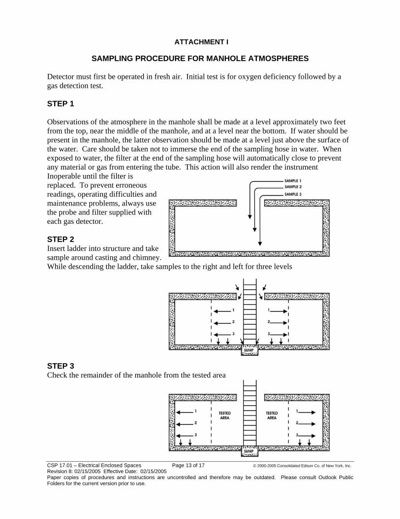
ATTACHMENT I
SAMPLING PROCEDURE FOR MANHOLE ATMOSPHERES Detector must first be operated in fresh air. Initial test is for oxygen deficiency followed by a gas detection test. STEP 1 Observations of the atmosphere in the manhole shall be made at a level approximately two feet from the top, near the middle of the manhole, and at a level near the bottom. If water should be present in the manhole, the latter observation should be made at a level just above the surface of the water. Care should be taken not to immerse the end of the sampling hose in water. When exposed to water, the filter at the end of the sampling hose will automatically close to prevent any material or gas from entering the tube. This action will also render the instrument Inoperable until the filter is replaced. To prevent erroneous readings, operating difficulties and maintenance problems, always use the probe and filter supplied with each gas detector.
CSP 17.01 – Electrical Enclosed Spaces Page 13 of 17 © 2000-2005 Consolidated Edison Co. of New York, Inc. Revision 8: 02/15/2005 Effective Date: 02/15/2005 Paper copies of procedures and instructions are uncontrolled and therefore may be outdated. Please consult Outlook Public Folders for the current version prior to use.
rom the tested area
STEP 2 Insert ladder into structure and take sample around casting and chimney. While descending the ladder, take samples to the right and left for three levels STEP 3 Check the remainder of the manhole f

CSP 17.01 – Electrical Enclosed Spaces Page 14 of 17 © 2000-2005 Consolidated Edison Co. of New York, Inc. Revision 8: 02/15/2005 Effective Date: 02/15/2005 Paper copies of procedures and instructions are uncontrolled and therefore may be outdated. Please consult Outlook Public Folders for the current version prior to use.
CSP 17.01 – Electrical Enclosed Spaces Page 14 of 17 © 2000-2005 Consolidated Edison Co. of New York, Inc. Revision 8: 02/15/2005 Effective Date: 02/15/2005 Paper copies of procedures and instructions are uncontrolled and therefore may be outdated. Please consult Outlook Public Folders for the current version prior to use.
TEP 4 Check remaining area at duct edges, comers, cracks, and other irregularities.
S

CSP 17.01 – Electrical Enclosed Spaces Page 15 of 17 © 2000-2005 Consolidated Edison Co. of New York, Inc. Revision 8: 02/15/2005 Effective Date: 02/15/2005 Paper copies of procedures and instructions are uncontrolled and therefore may be outdated. Please consult Outlook Public Folders for the current version prior to use.
Attachment 2 Moving Energized Cables
he following practices shall be employed when energized underground cables are to be moved on the Con Edison system. 1. Breaking conduit
a. Breaking out conduit shall be performed in accordance with the interim procedure for breaking out concrete and wooden duct
2. Visual inspection
a. Inside of Con Edison structures i. Initial inspection shall be performed by qualified Con Edison employee
to determine if cable can be moved safely. ii. Cable insulation/jacket and/or joints shall be free of cracks, tears,
exposed conductor, evidence of oil stains, swelling, or melting of the insulation – information contained in EO-1184, Bulletin 41, or any subsequently released Bulletins shall be used for guidance.
iii. Determine whether any “D” fault conditions exist as referenced in EO-1184.
iv. Cable shall be free from any visual defects that would prevent relocation.
v. Secondary cable shall not have any exposed or burnt apart conductors, burnt insulation, swollen or split insulation or lead cable sheath.
vi. Secondary joints, lead or rubber crab joints shall not have any exposed conductors. Joints shall not be swollen/split.
vii. After breaking out the ducts, the exposed cables shall be free from any of the above defects that would prevent relocation. Refer to EO-1184 or other appropriate spec.
viii. An electrically qualified Con Edison employee shall make identification of any 3M joints. 3M joints are to be handled in accordance with Distribution Engineering Bulletin No. 26. If an unsafe condition exists, the structure will fail inspection. Contractor entry will not be authorized until the condition(s) are corrected.
b. Outside of Con Edison structures i. Inspections of cable facilities that are located outside of Con Edison
structures shall be performed by competent/qualified personnel. ii. Cable(s) shall be free of cracks, tears, and evidence of oil stains,
swelling, or melting of the insulation. iii. Cable shall not have any exposed conductor.
3. Cable moving operations
a. Inside of Con Edison structures
T

CSP 17.01 – Electrical Enclosed Spaces Page 16 of 17 © 2000-2005 Consolidated Edison Co. of New York, Inc. Revision 8: 02/15/2005 Effective Date: 02/15/2005 Paper copies of procedures and instructions are uncontrolled and therefore may be outdated. Please consult Outlook Public Folders for the current version prior to use.
i. Con Edison person movement of primary cables. Information contained in EO-1184 and Distribution Engineering Bulletin No. 26 shall be used for guidance.
edges to prevent chaffing damage. Replace metallic fair-leaders with plastic type fair-leaders.
bending requirements specified in EO-1022 shall be followed.
v. Cables that have been removed from standard supports (rack arms tanchions) shall be supported by synthetic web slings having a
) inches. Slings shall be used in a basket hitch
of
ts. v at the
nd end of each work shift to ensure that no cracks, leaks,
b. Outside i. cables shall only be moved by personnel that have been
ii.
iii. oved from conduit shall be supported by
iv.
n support points shall be four (4) feet. v l
le
uit shall not be offset more than
vii. Each set of cables (cables from one duct) shall be moved individually. multiple ducts shall not be moved as a bundle.
ll be performed in a careful manner with the movement of cable under complete control at all times. There shall be no sudden movements of the cable or the conduit that contains cable.
nel shall perform
ii. Primary cables shall not be moved until plastic “fair-leaders” are positioned at the duct
iii. Cableiv. Secondary cables shall only be moved by electrically qualified
personnel.
and sminimum width of four (4configuration. Maximum distance between support points shall be four (4) feet.
vi. When primary joints are moved, the joint and about eight (8) inchescable on each side of the joint, shall be supported, cradled, and secured to prevent unintentional kinking where the cable meets thejoint.
vii. Cables / joints shall not be permitted to fall freely from temporary suppor
iii. All cable /joints supported by slings shall be visually inspected beginning aor other defects have developed. of Con Edison structures Primary qualified to perform this operation. Primary cables shall not be moved until plastic “fair-leaders” are positioned at the duct edges to prevent chaffing damage. Replace metallic fair-leaders with plastic type fair-leaders. Cables that have been remsynthetic web slings having a minimum width of four (4) inches. Slings shall be used in a basket hitch configuration. Conduits housing cables shall be supported using slings, cable, or rope. Conduits shall be supported in such manner as to maintain alignment with one another.
v. Maximum distance betweei. To prevent inadvertent over bending the cables, the maximum vertica
or horizontal offset between supports shall be one foot (1’) for cabthat is supported outside of conduit. For cable that is being movedwhile still installed in conduit, the condone foot per four-foot section of conduit.
Cables from viii. Relocation of cables sha
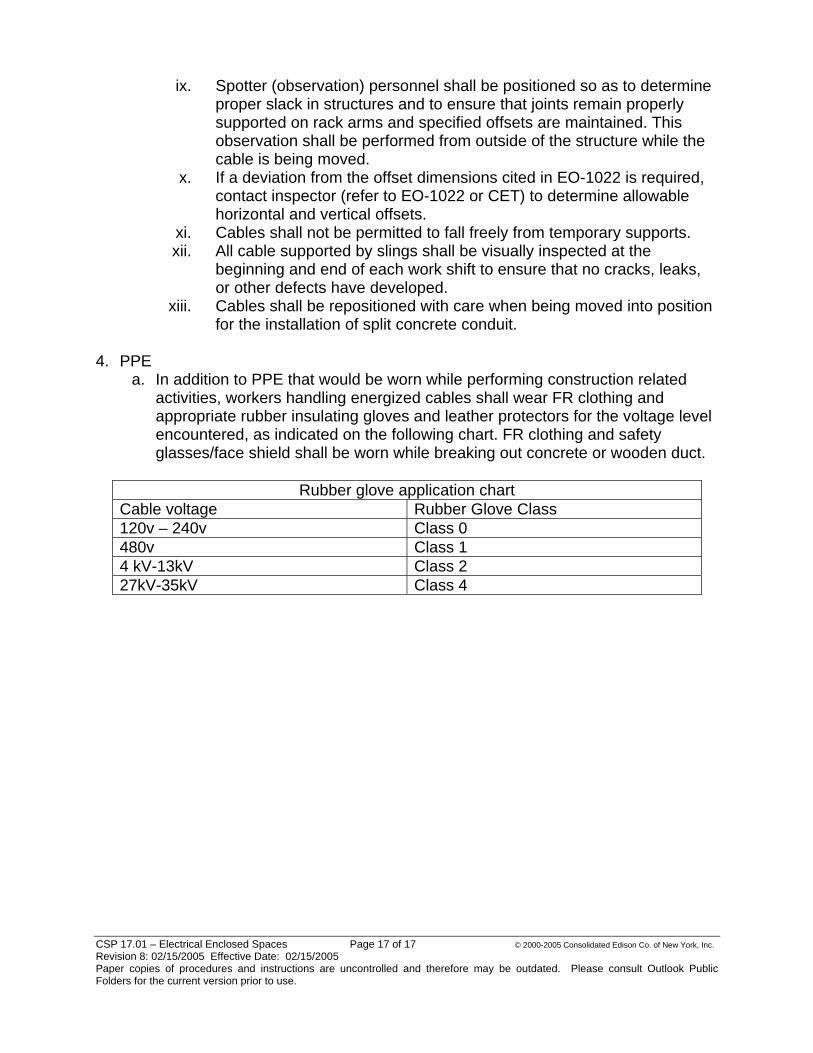
CSP 17.01 – Electrical Enclosed Spaces Page 17 of 17 © 2000-2005 Consolidated Edison Co. of New York, Inc. Revision 8: 02/15/2005 Effective Date: 02/15/2005 Paper copies of procedures and instructions are uncontrolled and therefore may be outdated. Please consult Outlook Public Folders for the current version prior to use.
ix ine
d offsets are maintained. This the
x. O-1022 is required,
xi. l not be permitted to fall freely from temporary supports. x
xiii. stallation of split concrete conduit.
4. PPE
a. In additioactivities, workers handling energized cables shall wear FR clothing and ap ri level encountered, as indicated on the following chart. FR clothing and safety g s/
on chart
. Spotter (observation) personnel shall be positioned so as to determproper slack in structures and to ensure that joints remain properly supported on rack arms and specifieobservation shall be performed from outside of the structure whilecable is being moved. If a deviation from the offset dimensions cited in Econtact inspector (refer to EO-1022 or CET) to determine allowable horizontal and vertical offsets. Cables shal
ii. All cable supported by slings shall be visually inspected at the beginning and end of each work shift to ensure that no cracks, leaks, or other defects have developed. Cables shall be repositioned with care when being moved into position for the in
n to PPE that would be worn while performing construction related
prop ate rubber insulating gloves and leather protectors for the voltage
lasse face shield shall be worn while breaking out concrete or wooden duct.
Rubber glove applicatiC Rubber Glove Class able voltage 120v – 240v Class 0 480v Class 14 kV-13kV Class 2 27kV-35kV Class 4
. . . . . . .. . .
96
N: EO-10,359 (Periodic Underground Distribution Structure Inspections)
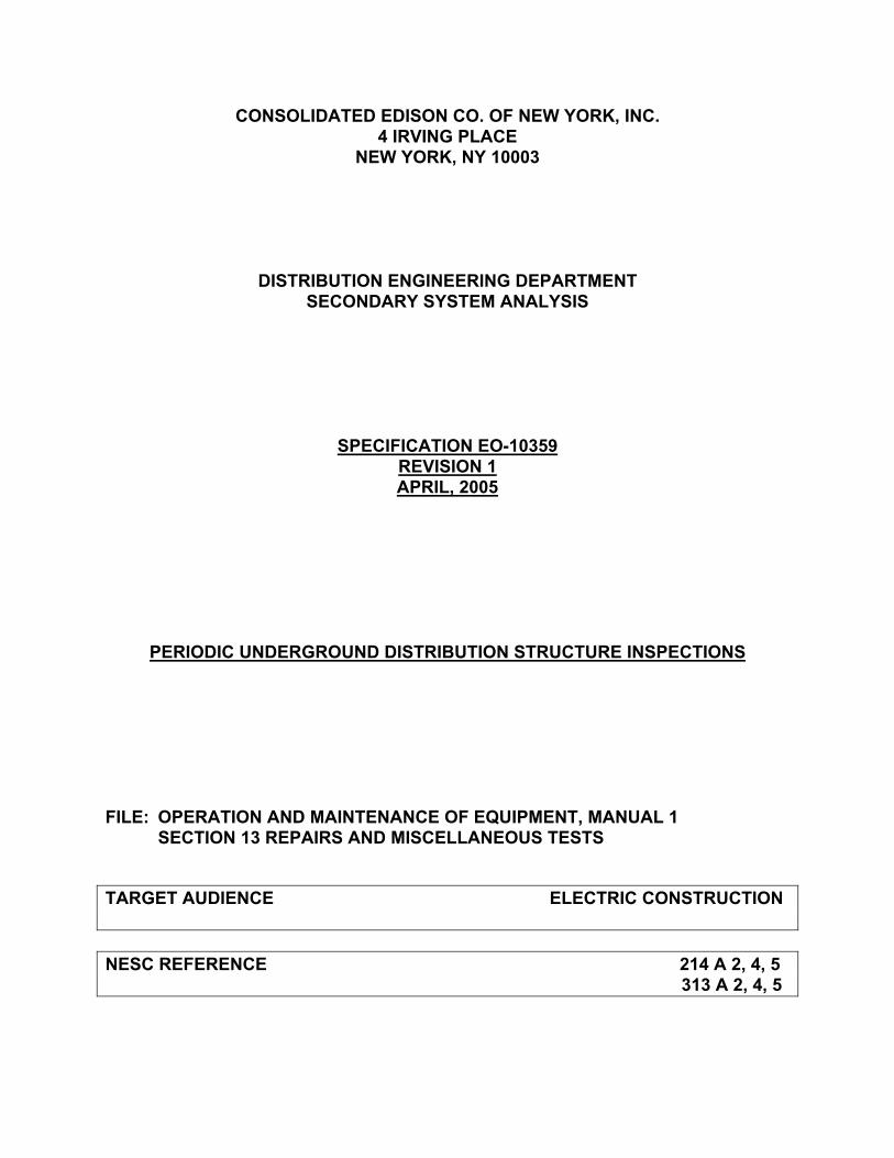
CONSOLIDATED EDISON CO. OF NEW YORK, INC. 4 IRVING PLACE
NEW YORK, NY 10003
DISTRIBUTION ENGINEERING DEPARTMENT SECONDARY SYSTEM ANALYSIS
SPECIFICATION EO-10359 REVISION 1 APRIL, 2005
PERIODIC UNDERGROUND DISTRIBUTION STRUCTURE INSPECTIONS
FILE: OPERATION AND MAINTENANCE OF EQUIPMENT, MANUAL 1 SECTION 13 REPAIRS AND MISCELLANEOUS TESTS
TARGET AUDIENCE ELECTRIC CONSTRUCTION NESC REFERENCE 214 A 2, 4, 5 313 A 2, 4, 5
Operation & Maintenance of Equipment 2 EO-10359 Revision 1 Manual No. 1, Sect 13 April 2005
TABLE OF CONTENTS
1.0 PURPOSE...........................................................................................................3
2.0 APPLICATION.....................................................................................................3
3.0 WHEN TO PERFORM AN UNDERGROUND INSPECTION? ............................3
4.0 TYPES OF INSPECTIONS..................................................................................4
5.0 PERFORMANCE OF INSPECTION....................................................................4
6.0 INSPECTION CYCLE..........................................................................................6
7.0 STRAY VOLTAGE TESTING DURING INSPECTIONS AND DURING WORK IN UNDERGROUND STRUCTURES.......................................................................6
8.0 FILLING OUT THE UNDERGROUND INSPECTION FORM ..............................7
9.0 PERMANENT RECORD OF STRUCTURE INSPECTIONS .............................11
10.0 REPAIR OF CONDITIONS FOUND ON INSPECTION OF UNDERGROUND DISTRIBUTION STRUCTURES........................................................................11
11.0 REFERENCE DOCUMENTS & SPECIFICATIONS ..........................................12
12.0 APPENDIX A: INSPECTION FORM FOR UG DIST. STRUCTURES ...............14

Operation & Maintenance of Equipment 3 EO-10359 Revision 1 Manual No. 1, Sect 13 April 2005
Periodic Underground Distribution Structure Inspections
1.0 PURPOSE 1.1. This specification describes periodic underground distribution structure
inspections to comply with the Public Service Commission’s Electric Safety Standards issued in Case 04-M-0159 for the following: 1.1.1. All underground electric distribution structures such as manholes,
service boxes and vaults. 1.1.2. All cable, joints, transformers, network protectors, etc. contained in
underground distribution structures and underground residential distribution (URD) structures.
1.2. All work and operating procedures shall be in accordance with the provisions of the “General Instructions Governing Work on System Electrical Equipment,” “General Instructions Governing Work on Overhead and URD System Electrical Equipment” and the “General Rules and Regulations”.
2.0 APPLICATION 2.1. All Underground, I&A Services, I&A Networks, M&CS, and Quality Assurance
personnel that enter electric distribution structures including, manholes, boxes, and vaults that contain/support primary or secondary cables and/or equipment.
3.0 WHEN TO PERFORM AN UNDERGROUND INSPECTION? 3.1. An Underground, I&A Services, I&A Networks, M&CS, and Quality Assurance
crew should perform an underground inspection on/in every distribution structure that the crew enters to perform work. All crews entering underground structures shall follow approved manhole entry procedures in CSP 17.01, including testing for stray voltage (See Section 7), and should conduct the inspection at the time of initial entry into the structure. If a structure inspection has been documented within the last 7-days, another documented inspection is not required. If a repair is made, then an inspection shall be documented, regardless if 7-days have not passed. The crew shall test the structure for stray voltage at the conclusion of work in the structure and at the end of each work period before leaving the site unless relieved by another crew (see Section 7).
3.2. Scheduled or Targeted underground inspections. A Scheduled inspection is conducted to ensure that a structure is inspected on its 5-year cycle. A Targeted inspection is conducted as part of the secondary upgrade program.
3.3. Inspections of customer manholes, or service boxes are not required. If a
Operation & Maintenance of Equipment 4 EO-10359 Revision 1 Manual No. 1, Sect 13 April 2005
defect is identified in/on customer structures they should be reported to Energy Services for follow-up with the customer.
4.0 TYPES OF INSPECTIONS 4.1. Underground Inspection – An inspection of an underground distribution
structure, such as service boxes, manholes, pull boxes, vaults, etc. and the electric equipment contained in the structure that are not normally buried. The inspection shall be performed in accordance with Paragraph 8.0.
4.2. Critical Manhole Inspection - Critical manholes are electric distribution underground structures where, if problems occurred, could have a major impact on the distribution system. Depending on operating region, examples of critical manholes are: the first feeder manholes leaving a substation, structures with three (3) or more feeders serving the same network, structures with more than three (3) network feeders serving more than one network and other structures selected by the Region’s Manager of Electric Operations Engineering. Transmission manholes containing distribution cables and splices shall be inspected as Critical manholes. Annually, each Region’s Manager of Electric Operations/Engineering should establish and issue the list of critical manholes in the region and then have these structures identified as critical manholes.
4.3. Joint Regulator Inspections – see EO-6141.
5.0 PERFORMANCE OF INSPECTION 5.1. Underground distribution structures should be inspected by visual
examination of the structure and its equipment to identify conditions that can cause or lead to safety hazards or adverse affects on the performance of the structure or equipment. In particular, the inspection should determine whether any of the conditions stated below in subsections 5.4.1 through 5.4.17 are present. These conditions are listed in sections “B” through “R” of the “UG Structure Inspection Form (EO-10359)” form.
5.1.1. D-Fault Tag (EO-1184) or Environmental Tag Present – A chimney tag found installed after the structure cover has been removed.
5.1.2. Flush Required to Complete Inspection – A flush is required when the presence of liquids and/or debris in a structure prevent a full and complete visual inspection of all components of the structure and the equipment in the structure.
5.1.3. D-Fault (EO-1184) or Environmental Condition identified during inspection – A D-Fault or Environmental condition that was not previously identified is observed during the inspection.
Operation & Maintenance of Equipment 5 EO-10359 Revision 1 Manual No. 1, Sect 13 April 2005
5.1.4. Stray Voltage – A voltage found present on a conducting material that is not intended to be energized.
5.1.5. Cable or Crab in Contact with Cover/Frame (Bulletin 51) – A secondary or service conductor found in contact or within 6” of the metallic structure cover or frame.
5.1.6. Improperly Sealed Secondary End Cap(s) (Bulletin 49) – A secondary or service conductor that is not sealed in accordance with specification EO-2509-C or EO-10979-C.
5.1.7. Voltage Present on Metallic Conduit or Lead Sheath (Stray Voltage) - A voltage found present on the lead jacket of a main or service conductor or accessible metallic secondary or service duct that is not intended to be energized.
5.1.8. Unsealed Service Duct (EO-1100) (EO-6217-C) – A service duct found not sealed in accordance with EO-1100 or EO-6217-C.
5.1.9. Cover Damage/Needs Regrade/Structure Damage – A structure cover found cracked, damaged, above grade or below grade. A vented cover with the holes clogged that can not be cleared. A structure condition with large cracks in walls or ceiling, steel support beams defective, etc. A URD structure with broken baffles or doors that do not close and lock.
5.1.10. Sump Pump Inoperable/Ungrounded (EO-12160-C) – A sump pump that does not operate when the float is lifted or a sump pump that is found not grounded in accordance with EO-12160-C.
5.1.11. Exposed Conductor/Visible Burnouts – A condition where secondary or service cables are burning or conductor is exposed.
5.1.12. Damaged Neutral Cable/Connections – A condition where the neutrals do not have the proper number of indents, the aluminum cables are not connected in accordance with EO-5403, the bonds are broken on lead mains or services, damaged neutral bus, or connections are broken apart.
5.1.13. Damaged Secondary Service(s)/Main(s)/Crab(s)/Splice(s) - Secondary conditions such as swollen, damaged, peeling, cracked, or burnt crabs/cable, jacket rolled back, damaged U-splices or connections without the proper number of indents.
5.1.14. Damaged Primary Feeder Cable(s)/Joint(s) – A condition on primary cable such as swollen joints-below-max, collapsed joints, feeder on floor that can not be re-racked, damaged elbows, etc. that are not D-Faults.
Operation & Maintenance of Equipment 6 EO-10359 Revision 1 Manual No. 1, Sect 13 April 2005
5.1.15. Structure Conductor Upgrade - A condition where the secondary cables not properly racked, the hole is very congested, there are no remaining pockets/tails for the required work within the structure or limited space for the employee to work safely.
5.1.16. Main Requires Replacement – A main that is recommended for replacement due to cracked lead armor, corroded lead armor where the insulation is exposed, or insulation is cracked, brittle, or baked.
5.1.17. Service Requires Replacement – A Service that is recommended for replacement due to cracked lead armor, corroded lead armor where the insulation is exposed, or insulation is cracked, brittle, or baked.
6.0 INSPECTION CYCLE 6.1. The underground inspections should be conducted according to the following
schedule: 6.1.1. Underground Inspection – At least every 5-years. 6.1.2. Critical Manhole Inspection – Every 3 years. 6.1.3. Tunnels (Con Edison) – 5 years. 6.1.4. Manholes with Joint Regulators – see EO-6141 for cycle.
7.0 STRAY VOLTAGE TESTING DURING INSPECTIONS AND DURING WORK IN UNDERGROUND STRUCTURES 7.1. All crews entering underground structures for any purpose shall follow
approved manhole entry procedures in CSP 17.01, including testing for stray voltage. The crew shall also test for stray voltage at the conclusion of work in the structure and at the end of each work period before leaving the site unless relieved by another crew.
7.2. Testing for stray voltage shall be conducted according to the procedures and using the approved device stated in EO-10129 and EO-100175.
7.3. Stray voltage testing includes a test of the exterior metallic surfaces (cover and rim) of any distribution structure, such as manhole covers, service box covers, and vault gratings. See Bulletin #39. Stray voltage testing inside the structure includes a test of the lead jacket of a main or service conductor and accessible metallic secondary or service duct.
7.4. Where stray voltage is found, the procedures stated in Bulletin #48 shall be followed. All locations identified with a stray voltage shall be immediately made safe or manned continually until the condition causing the stray voltage is made safe. The condition that caused the stray voltage must be repaired
Operation & Maintenance of Equipment 7 EO-10359 Revision 1 Manual No. 1, Sect 13 April 2005
within 45 days of discovering stray voltage.
8.0 FILLING OUT THE UNDERGROUND INSPECTION FORM 8.1. Crews should use the “UG Structure Inspection Form (EO-10359)” in
Appendix A to record the results of each underground inspection of an underground distribution structure. Refer to the UG Structure Inspection Form in Appendix A for Section 8 of this specification.
8.2. The top of form consists of general information relating to 8.2.1. The name and employee number of the person conducting the
inspection. 8.2.2. The date the inspection was completed. 8.2.3. The Region in which the structure is located. 8.2.4. The appropriate Municipality for Westchester 8.2.5. The Department of the employee conducting the inspection. 8.2.6. The Location of the structure relating to street address. 8.2.7. The Parking restrictions. 8.2.8. The Structure type (code abbreviations for each type of structure
are provided) 8.2.9. The Structure number. 8.2.10. The presence of a Joint Regulator within the structure. 8.2.11. The location of the structure relating to the street, sidewalk, or
other. 8.2.12. The M&S plate number of the structure. 8.2.13. The Cover type on the structure.
8.3. Item A on the inspection form is the reason for inspection and shall be marked as follows: 8.3.1. A Scheduled or Targeted inspection conducted as part of the upgrade
program or to ensure the structure is inspected on cycle, shall be entered as Code 1.
8.3.2. An inspection of a Manhole conducted as part of the Critical Manhole program shall be entered as Code 2.
8.3.3. An inspection conducted in conjunction with regular work within the structure such as installing services, splicing primary or secondary, etc. shall be entered as Code 3.
8.3.4. An inspection conducted during follow-up repairs identified during a

Operation & Maintenance of Equipment 8 EO-10359 Revision 1 Manual No. 1, Sect 13 April 2005
structure inspection shall be entered as Code 4.
8.3.5. Item A also has a yes/no box called “Defects Found.” An answer of “No” in the box means that all Items from B through R have an answer of “No”. An answer of “Yes” in the box means that any one or more of Items B through R has an answer of “Rep”, or “Yes.”
8.4. If the structure has been found with a D-Fault tag, do not enter the structure, and refer to EO-1184 for appropriate action. No ECS ticket needs to be created as a result of this inspection. Item B on the inspection form shall be marked as “Yes”. Item S on the inspection form shall be marked ”Stop,” the D-Fault Tag number recorded on the form, and the inspection shall cease.
8.5. If the structure has been found with an Environmental Tag, refer to the General Environmental Instructions for appropriate action. Item B on the inspection form shall be marked as “Yes” and Item S shall be marked “Stop,” the Environmental Tag number recorded on the form, and the inspection shall cease.
8.6. If the structure requires a flush to conduct a full and complete visual inspection, then the flush should be reported to the appropriate department. The flush number, if appropriate, should be recorded on the form for further follow-up. The inspection is incomplete. Item C shall be marked “Yes” on the inspection form and Item S shall be marked “Stop,” the flush number recorded on the form, and the inspection shall cease.
8.7. If a D-Fault is identified during the inspection, exit the structure, and refer to EO-1184 for appropriate action. In addition, this D-Fault shall be recorded in the Distribution Fault Tracking Application. Item D shall be marked “Yes,” Item S shall be marked “Stop,” and the inspection shall cease.
8.8. If the structure is found with an environmental condition, the condition shall be reported according to the General Environmental Instructions. Item D on the inspection form shall be marked “Yes,” Item S on the inspection form shall be marked “Stop,” and the inspection shall cease.
8.9. If the structure has been found with stray voltage, protect the location, call the appropriate Control Center to report the condition, and begin troubleshooting activities. The Control Center shall initiate an ECS ticket with a trouble type of ENE. The field crew and Control Center shall coordinate the collection of the information necessary in Bulletin #48. Item E on the inspection form should be marked “Rep” (repaired) when the stray voltage condition has been repaired.
8.10. If secondary/services cables/crabs are found in contact with the frame/cover or within 6” of the frame/cover, they should be reshaped to eliminate this contact and provide at least 6” clearance. If reshaping cannot be performed

Operation & Maintenance of Equipment 9 EO-10359 Revision 1 Manual No. 1, Sect 13 April 2005
then a secondary barrier shall be installed in accordance with Bulletin #51. In addition to installing the secondary barrier, the structure requires a Structure Conductor Upgrade and an enlargement review. If a barrier is installed, Item F should be marked “Rep” and Item P should be marked “Yes” on the inspection form.
8.11. If secondary/services cables/crabs are found with the ends not protected in accordance with EO-2509-C or EO-10979-C, they shall be repaired upon discovery and Item G shall be marked “Rep”.
8.12. If voltage is found on the metallic sheath or accessible metallic conduit of a secondary or service conductor, the condition shall be considered a stray voltage and immediate repairs initiated. Item H shall be marked “Rep” when the stray voltage condition has been corrected.
8.13. If an unsealed service duct is observed during the inspection, it shall be sealed during the inspection and item I shall be marked “Rep”.
8.14. When the structure has been determined to require a regrade or a cover replacement, Item J on the inspection form should be marked “Yes”, and an ECS ticket should be generated with a trouble type of SIP. This ticket should be office completed and receive a DOCS referral to the organization in the region responsible such as Sub-Surface Construction (SSC) or Construction Management (CM) for further evaluation of the required work. Do not refer these ECS tickets as “FYI”. This department should evaluate the required work. Examples of appropriate DOCS referral codes are:
Region Work Code Queue
Brooklyn BEC2CMAVL
Queens QECESINBOX
Staten Island S.CAI.BT
Manhattan MI.ES.BT
Westchester NSSS
Bronx
ES0007
NSSS
8.15. If the sump pump does not operate when the float is lifted or the pump is found improperly grounded Item K shall be marked “Yes.” If the sump pump or grounding is repaired Item K shall be marked “Rep.” If the structure does not require a sump pump, Item K shall be marked “No.”
8.16. If exposed secondary/service conductors or visible burnouts are found during the inspection, they must be repaired immediately or referred to Control Center for repair. Item L on the inspection should be marked “Rep” if the repair is made at the time of the inspection. If the condition has been referred to the Control Center, then Item L should be marked “Yes”. Do not
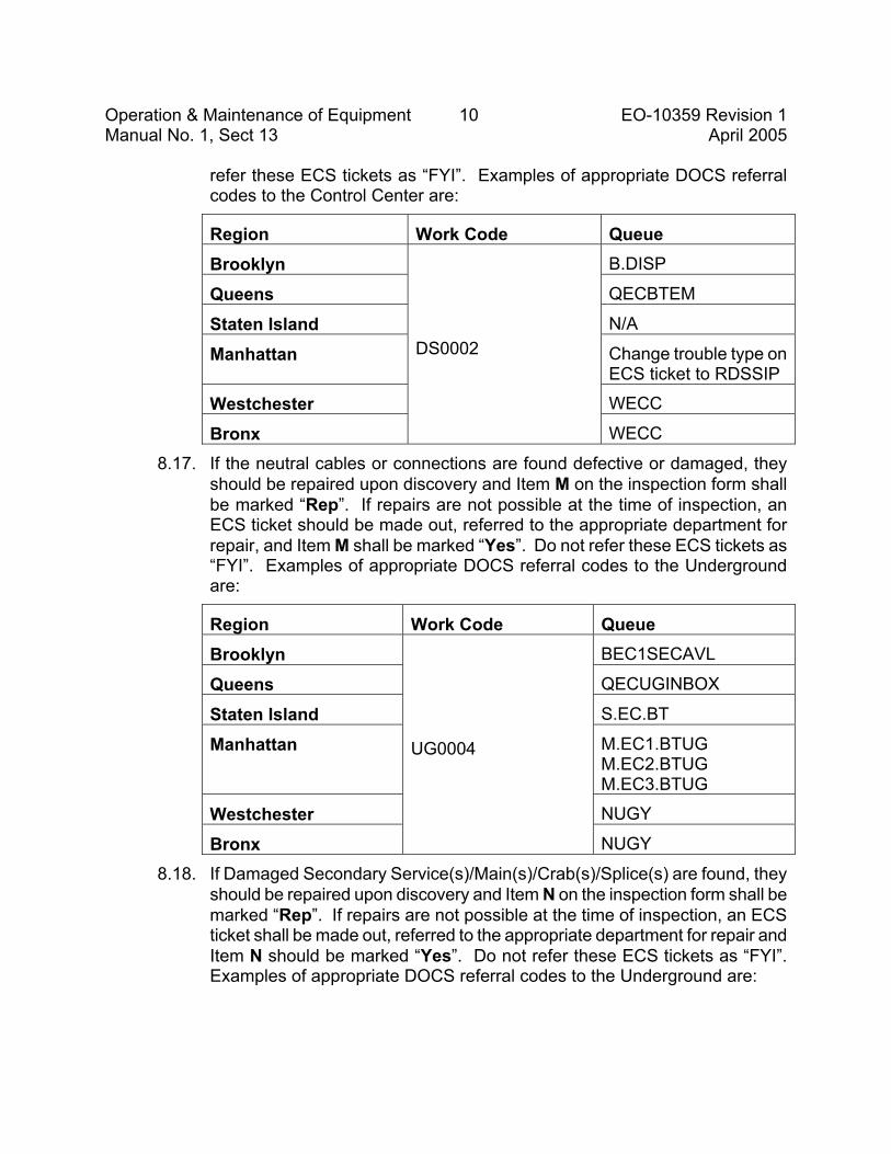
Operation & Maintenance of Equipment 10 EO-10359 Revision 1 Manual No. 1, Sect 13 April 2005
refer these ECS tickets as “FYI”. Examples of appropriate DOCS referral codes to the Control Center are:
Region Work Code Queue Brooklyn B.DISP
Queens QECBTEM
Staten Island N/A
Manhattan Change trouble type on ECS ticket to RDSSIP
Westchester WECC
Bronx
DS0002
WECC
8.17. If the neutral cables or connections are found defective or damaged, they should be repaired upon discovery and Item M on the inspection form shall be marked “Rep”. If repairs are not possible at the time of inspection, an ECS ticket should be made out, referred to the appropriate department for repair, and Item M shall be marked “Yes”. Do not refer these ECS tickets as “FYI”. Examples of appropriate DOCS referral codes to the Underground are:
Region Work Code Queue Brooklyn BEC1SECAVL
Queens QECUGINBOX
Staten Island S.EC.BT
Manhattan M.EC1.BTUG M.EC2.BTUG M.EC3.BTUG
Westchester NUGY
Bronx
UG0004
NUGY
8.18. If Damaged Secondary Service(s)/Main(s)/Crab(s)/Splice(s) are found, they should be repaired upon discovery and Item N on the inspection form shall be marked “Rep”. If repairs are not possible at the time of inspection, an ECS ticket shall be made out, referred to the appropriate department for repair and Item N should be marked “Yes”. Do not refer these ECS tickets as “FYI”. Examples of appropriate DOCS referral codes to the Underground are:

Operation & Maintenance of Equipment 11 EO-10359 Revision 1 Manual No. 1, Sect 13 April 2005
Region Work Code Queue Brooklyn BEC1SECAVL
Queens QECUGINBOX
Staten Island S.EC.BT
Manhattan M.EC1.BTUG M.EC2.BTUG M.EC3.BTUG
Westchester NUGY
Bronx
UG0006
NUGY
8.19. If Damaged Primary Feeder Cable(s)/Joint(s) or other primary conditions that are not D-Faults are found during the inspection, report the condition to the appropriate Regional Control Center.
8.20. If a Structure Conductor Upgrade is required within the structure, an ECS ticket should be made out and closed out unless Tier One items remain open. Item P should be marked “Yes” on the inspection form.
8.21. If a main is recommended for replacement, Item Q should be marked “Yes”. An ECS ticket shall be generated with trouble type SIP. Add all pertinent data about the main and service in the remarks of the ECS ticket and close the ECS ticket unless Tier One items remain open.
8.22. If a service is recommended for replacement, Item R should be marked “Yes”. An ECS ticket should be generated with trouble type SIP. Add all pertinent data about the main and service in the remarks of the ECS ticket and close the ECS ticket unless Tier One items remain open. See Section 8.2 for prioritization of Tier Two repairs.
8.23. Once all the preceding conditions have been observed, Item S on the inspection form shall be marked “Yes,” except when Items B, C, or D are marked “Yes,” in which case Item S shall be marked “Stop.”
9.0 PERMANENT RECORD OF STRUCTURE INSPECTIONS 9.1. The Stray Voltage Log shall be used as the permanent record of
underground distribution structures inspections. 9.2. The data on the “UG Structure Inspection Form (EO-10359)” form shall be
entered into the Stray Voltage Log.
10.0 REPAIR OF CONDITIONS FOUND ON INSPECTION OF UNDERGROUND DISTRIBUTION STRUCTURES 10.1. Crews performing an underground inspection are expected to make minor
Operation & Maintenance of Equipment 12 EO-10359 Revision 1 Manual No. 1, Sect 13 April 2005
repairs and should be equipped with material necessary to make such minor repairs, such as fairleaders, porcelains, shrink caps, shrink sleeves, etc.
10.2. Any repair work identified during the inspection should be initiated at the time of inspection. If repairs are not completed before Company forces leave the site, an ECS ticket shall be created and routed to the appropriate department for follow-up repairs. If multiple repairs are required, one ECS ticket should be issued indicating all required follow-up work. If repairs are completed before Company forces leave the site, an ECS ticket is not required unless stray voltage was found at the structure. All ECS tickets created as a result of an underground inspection should have a trouble code of “EDSSIP”, except structures found with stray voltage. Structures found with stray voltage, should have ECS tickets issued with a trouble code of “EDSENE.”
11.0 REFERENCE DOCUMENTS & SPECIFICATIONS 11.1. The following specifications and documents are referenced in this
specification: EO-10111 Schedule For Maintenance And Inspection Of URD
Subsurface Transformers EO-10113 Schedule For Maintenance And Inspection Of Padmounted
Transformers (Single / Three Phase), Padmounted Switchgear (PME) And T-Tap Boxes
EO-10110 Inspection And Maintenance Of Network Type Distribution Equipment
EO-6141 Maintenance of Oil Reservoirs on Distribution Feeders EO-6217-C Method Of Sealing Phase Grouped Cables And Conduits For
Services, Manholes, And Vaults EO-1184 Periodic Inspection, Maintenance and Reporting of
Distribution Underground Cables & Joints EO-1147 Secondary Cable Distribution Boxes EO-1022 Design Limitations of Primary Feeder Subway Systems
Operation & Maintenance of Equipment 13 EO-10359 Revision 1 Manual No. 1, Sect 13 April 2005 Won Choe (Signature on File)
Won Choe Secondary System Analysis Department Manager Distribution Engineering Department
Leo A. Scally
REVISION 1 Complete review and rewrite of specification. Removed the Overhead from this specification.
FILE Operation and Maintenance of Equip. Manual No. 1, Sect. 13 Repairs & Miscellaneous Tests
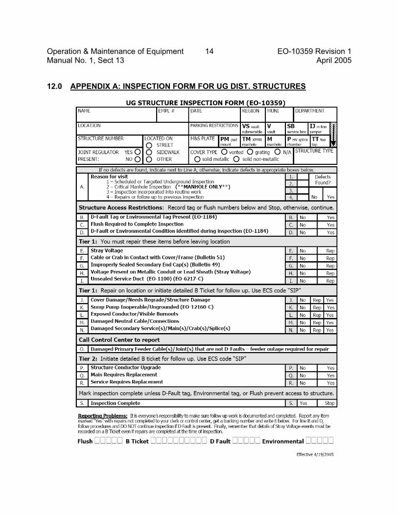
Operation & Maintenance of Equipment 14 EO-10359 Revision 1 Manual No. 1, Sect 13 April 2005
12.0 APPENDIX A: INSPECTION FORM FOR UG DIST. STRUCTURES

97
This page is intentionally left blank.
. . . . . . .. . .
98
O: Certification of Stray Voltage Testing
Stephen F. Wood, on this ___ day of January 2006, certifies as follows:
1. I am Vice President of Consolidated Edison Company of New York, Inc. (“Con Edison” or “the Company”).
2. I am responsible for overseeing Con Edison’s stray voltage testing program, and in that capacity I have monitored the Company’s stray voltage testing program during the twelve months ended November 30, 2005 (“the twelve month period”). During the twelve-month period, Con Edison instituted and diligently carried out a program designed to meet the stray voltage testing requirements of the Public Service Commission’s Safety Standards, issued and effective January 5, 2005 as modified by Order issued July 21, 2005 in Case 04-M-0159, Proceeding Instituting Safety Standards.
3. To the best of my knowledge, information, and belief, during the twelve month period, Con Edison identified and tested for stray voltage (i) all publicly accessible electric facilities owned by the Company, and (ii) all streetlights located in public thoroughfares in the Company’s service territory as identified through a good faith effort by the Company, except for such facilities that are identified in the Company’s Annual Report, submitted herewith.
________________________
Stephen F. Wood

99
This page is intentionally left blank.
. . . . . . .. . .
100
P: Certification of Inspections
Stephen F. Wood, on this ___ day of January 2006, certifies as follows:
1. I am Vice President of Consolidated Edison Company of New York, Inc. (“Con Edison” or “the Company”).
2. I am responsible for overseeing Con Edison’s electric facility inspection program, and in that capacity I have monitored the Company’s inspection program during the twelve months ended November 30, 2005 (“the twelve-month period”). During the twelve-month period, Con Edison instituted and diligently carried out a program designed to meet the inspection requirements established by the Public Service Commission’s Safety Standards, issued and effective January 5, 2005 as modified by Order issued July 21, 2005 in Case 04-M-0159, Proceeding Instituting Safety Standards.
3. To the best of my knowledge, information, and belief, Con Edison has visually inspected the requisite number of electric facilities during the twelve-month period, including the requirement to have conducted a visual inspection of at least 17% of its electric facilities through November 30, 2005.
________________________
Stephen F. Wood