Analysis of Stray Grain Formation in Single-Crystal Nickel ... · PDF file100 m ANALYSIS OF...
8
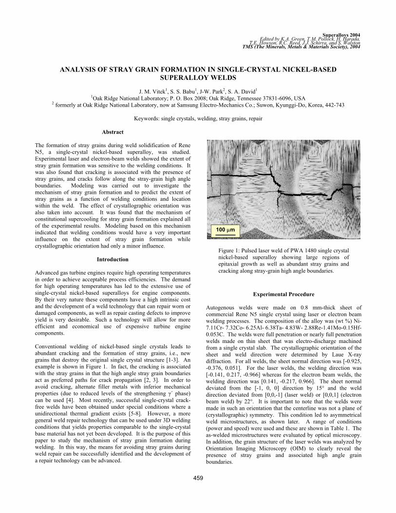
100 m ANALYSIS OF STRAY GRAIN FORMATION IN SINGLE-CRYSTAL NICKEL-BASED SUPERALLOY WELDS J. M. Vitek 1 , S. S. Babu 1 , J-W. Park 2 , S. A. David 1 1 Oak Ridge National Laboratory; P. O. Box 2008; Oak Ridge, Tennessee 37831-6096, USA 2 formerly at Oak Ridge National Laboratory, now at Samsung Electro-Mechanics Co.; Suwon, Kyunggi-Do, Korea, 442-743 Keywords: single crystals, welding, stray grains, repair Abstract The formation of stray grains during weld solidification of Rene N5, a single-crystal nickel-based superalloy, was studied. Experimental laser and electron-beam welds showed the extent of stray grain formation was sensitive to the welding conditions. It was also found that cracking is associated with the presence of stray grains, and cracks follow along the stray-grain high angle boundaries. Modeling was carried out to investigate the mechanism of stray grain formation and to predict the extent of stray grains as a function of welding conditions and location within the weld. The effect of crystallographic orientation was also taken into account. It was found that the mechanism of constitutional supercooling for stray grain formation explained all of the experimental results. Modeling based on this mechanism indicated that welding conditions would have a very important influence on the extent of stray grain formation while crystallographic orientation had only a minor influence. Introduction Advanced gas turbine engines require high operating temperatures in order to achieve acceptable process efficiencies. The demand for high operating temperatures has led to the extensive use of single-crystal nickel-based superalloys for engine components. By their very nature these components have a high intrinsic cost and the development of a weld technology that can repair worn or damaged components, as well as repair casting defects to improve yield is very desirable. Such a technology will allow for more efficient and economical use of expensive turbine engine components. Conventional welding of nickel-based single crystals leads to abundant cracking and the formation of stray grains, i.e., new grains that destroy the original single crystal structure [1-3]. An example is shown in Figure 1. In fact, the cracking is associated with the stray grains in that the high angle stray grain boundaries act as preferred paths for crack propagation [2, 3]. In order to avoid cracking, alternate filler metals with inferior mechanical properties (due to reduced levels of the strengthening ´ phase) can be used [4]. Most recently, successful single-crystal crack- free welds have been obtained under special conditions where a unidirectional thermal gradient exists [5-8]. However, a more general weld repair technology that can be used under 3D welding conditions that yields properties comparable to the single-crystal base material has not yet been developed. It is the purpose of this paper to study the mechanism of stray grain formation during welding. In this way, the means for avoiding stray grains during weld repair can be successfully identified and the development of a repair technology can be advanced. Experimental Procedure Autogenous welds were made on 0.8 mm-thick sheet of commercial Rene N5 single crystal using laser or electron beam welding processes. The composition of the alloy was (wt %) Ni- 7.11Cr- 7.32Co- 6.25Al- 6.38Ta- 4.83W- 2.88Re-1.41Mo-0.15Hf- 0.053C. The welds were full penetration or nearly full penetration welds made on thin sheet that was electro-discharge machined from a single crystal slab. The crystallographic orientation of the sheet and weld direction were determined by Laue X-ray diffraction. For all welds, the sheet normal direction was [-0.925, -0.376, 0.051]. For the laser welds, the welding direction was [-0.141, 0.217, -0.966] whereas for the electron beam welds, the welding direction was [0.141, -0.217, 0.966]. The sheet normal deviated from the [-1, 0, 0] direction by 15° and the weld direction deviated from [0,0,-1] (laser weld) or [0,0,1] (electron beam weld) by 22°. It is important to note that the welds were made in such an orientation that the centerline was not a plane of (crystallographic) symmetry. This condition led to asymmetrical weld microstructures, as shown later. A range of conditions (power and speed) were used and these are shown in Table 1. The as-welded microstructures were evaluated by optical microscopy. In addition, the grain structure of the laser welds was analyzed by Orientation Imaging Microscopy (OIM) to clearly reveal the presence of stray grains and associated high angle grain boundaries. Figure 1: Pulsed laser weld of PWA 1480 single crystal nickel-based superalloy showing large regions of epitaxial growth as well as abundant stray grains and cracking along stray-grain high angle boundaries. 459 Superalloys 2004 Edited by K.A. Green, T.M. Pollock, H. Harada, TMS (The Minerals, Metals & Materials Society), 2004 T.E. Howson, R.C. Reed, J.J. Schirra, and S, Walston
Transcript of Analysis of Stray Grain Formation in Single-Crystal Nickel ... · PDF file100 m ANALYSIS OF...
100 m100 m100 m
ANALYSIS OF STRAY GRAIN FORMATION IN SINGLE-CRYSTAL NICKEL-BASED
SUPERALLOY WELDS
J. M. Vitek1, S. S. Babu1, J-W. Park2, S. A. David1
1Oak Ridge National Laboratory; P. O. Box 2008; Oak Ridge, Tennessee 37831-6096, USA 2 formerly at Oak Ridge National Laboratory, now at Samsung Electro-Mechanics Co.; Suwon, Kyunggi-Do, Korea, 442-743
Keywords: single crystals, welding, stray grains, repair
Abstract
The formation of stray grains during weld solidification of Rene
N5, a single-crystal nickel-based superalloy, was studied.
Experimental laser and electron-beam welds showed the extent of
stray grain formation was sensitive to the welding conditions. It
was also found that cracking is associated with the presence of
stray grains, and cracks follow along the stray-grain high angle
boundaries. Modeling was carried out to investigate the
mechanism of stray grain formation and to predict the extent of
stray grains as a function of welding conditions and location
within the weld. The effect of crystallographic orientation was
also taken into account. It was found that the mechanism of
constitutional supercooling for stray grain formation explained all
of the experimental results. Modeling based on this mechanism
indicated that welding conditions would have a very important
influence on the extent of stray grain formation while
crystallographic orientation had only a minor influence.
Introduction
Advanced gas turbine engines require high operating temperatures
in order to achieve acceptable process efficiencies. The demand
for high operating temperatures has led to the extensive use of
single-crystal nickel-based superalloys for engine components.
By their very nature these components have a high intrinsic cost
and the development of a weld technology that can repair worn or
damaged components, as well as repair casting defects to improve
yield is very desirable. Such a technology will allow for more
efficient and economical use of expensive turbine engine
components.
Conventional welding of nickel-based single crystals leads to
abundant cracking and the formation of stray grains, i.e., new
grains that destroy the original single crystal structure [1-3]. An
example is shown in Figure 1. In fact, the cracking is associated
with the stray grains in that the high angle stray grain boundaries
act as preferred paths for crack propagation [2, 3]. In order to
avoid cracking, alternate filler metals with inferior mechanical
properties (due to reduced levels of the strengthening ´ phase)
can be used [4]. Most recently, successful single-crystal crack-
free welds have been obtained under special conditions where a
unidirectional thermal gradient exists [5-8]. However, a more
general weld repair technology that can be used under 3D welding
conditions that yields properties comparable to the single-crystal
base material has not yet been developed. It is the purpose of this
paper to study the mechanism of stray grain formation during
welding. In this way, the means for avoiding stray grains during
weld repair can be successfully identified and the development of
a repair technology can be advanced.
Experimental Procedure
Autogenous welds were made on 0.8 mm-thick sheet of
commercial Rene N5 single crystal using laser or electron beam
welding processes. The composition of the alloy was (wt %) Ni-
7.11Cr- 7.32Co- 6.25Al- 6.38Ta- 4.83W- 2.88Re-1.41Mo-0.15Hf-
0.053C. The welds were full penetration or nearly full penetration
welds made on thin sheet that was electro-discharge machined
from a single crystal slab. The crystallographic orientation of the
sheet and weld direction were determined by Laue X-ray
diffraction. For all welds, the sheet normal direction was [-0.925,
-0.376, 0.051]. For the laser welds, the welding direction was
[-0.141, 0.217, -0.966] whereas for the electron beam welds, the
welding direction was [0.141, -0.217, 0.966]. The sheet normal
deviated from the [-1, 0, 0] direction by 15° and the weld
direction deviated from [0,0,-1] (laser weld) or [0,0,1] (electron
beam weld) by 22°. It is important to note that the welds were
made in such an orientation that the centerline was not a plane of
(crystallographic) symmetry. This condition led to asymmetrical
weld microstructures, as shown later. A range of conditions
(power and speed) were used and these are shown in Table 1. The
as-welded microstructures were evaluated by optical microscopy.
In addition, the grain structure of the laser welds was analyzed by
Orientation Imaging Microscopy (OIM) to clearly reveal the
presence of stray grains and associated high angle grain
boundaries.
Figure 1: Pulsed laser weld of PWA 1480 single crystal
nickel-based superalloy showing large regions of
epitaxial growth as well as abundant stray grains and
cracking along stray-grain high angle boundaries.
459
Superalloys 2004Edited by K.A. Green, T.M. Pollock, H. Harada,
TMS (The Minerals, Metals & Materials Society), 2004T.E. Howson, R.C. Reed, J.J. Schirra, and S, Walston
Modeling Procedures
Previous work analyzed the weld pool and its thermal properties
using a finite element code [3]. That analysis allowed for a
reasonably precise replication of the weld pool shape. However,
the analysis procedure was numerically intensive and only a
limited portion of the entire weld pool was evaluated in terms of
dendrite growth behavior. In the present study, a less tedious,
simpler thermal analysis was employed that allowed for a
complete analysis over the entire weld pool surface. In this
procedure, the Rosenthal solution for heat flow was utilized [9].
This analysis only considers conductive heat flow. Furthermore, a
3D thermal analysis was done. The actual weld cross sections
were found to be intermediate between the 2D and 3D conditions
in the Rosenthal analysis. The 2D case considers a weld pool that
does not vary with depth, while the 3D case considers a weld pool
that is only a partial penetration weld. While neither of these two
simple cases accurately reflects the real cross-section of the welds,
the 3D case was used because it has an inherent symmetry that
allows for an integrated analysis over the entire weld pool surface
that takes into account the variation in thermal parameters
(thermal gradient and solidification front growth velocity) that is
found in welds. Thus, the thermal modeling was more qualitative
in nature, but it allowed for a thorough evaluation of trends that
result from the variation in welding conditions. The same
Rosenthal model has been shown to be effective in describing
general behavior in other studies as well [10].
Table 1: Conditions Used for Experimental Welds
Process Speed (m/s) Power (W)
Laser Beam 0.0042 420
0.0127 804
0.0212 840
Electron Beam 0.0042 250
0.0127 320
0.0212 612
The simple Rosenthal 3D thermal analysis provided the basis for
evaluating the thermal gradient and solidification front orientation
over the entire weld pool surface. The weld pool surface was
defined by the 1417°C isotherm, which is between the liquidus
and solidus for the Rene N5 alloy. The thermal analysis was
combined with a previously developed geometric model that
identifies the dendrite growth direction in single crystal welds as a
function of the initial sample orientation and weld direction [11,
12]. This combined analysis yielded a description of the dendritic
growth conditions (thermal gradient, growth velocity) over the
entire weld pool surface. Recently Gäumann et al have
considered the nucleation and growth of crystals ahead of an
advancing single crystal dendritic growth front [13]. Such
nucleation and growth, due to constitutional supercooling ahead
of the advancing solidification front, may lead to the formation of
stray grains. The analysis of Gäumann et al was combined with
the thermal analysis to determine the susceptibility of the nickel-
based single crystals to stray grain formation during welding. As
a result of the intrinsic symmetry of the Rosenthal solution, the
susceptibility to stray grain formation could be integrated over the
entire weld pool surface in a reasonable manner. The parameters
used in the stray grain analysis were the same as those used by
Gäumann since their work was on a comparable nickel-based
superalloy. Details regarding the modeling procedure are
provided elsewhere [14].
Results
Welding
Representative optical micrographs of the laser and electron beam
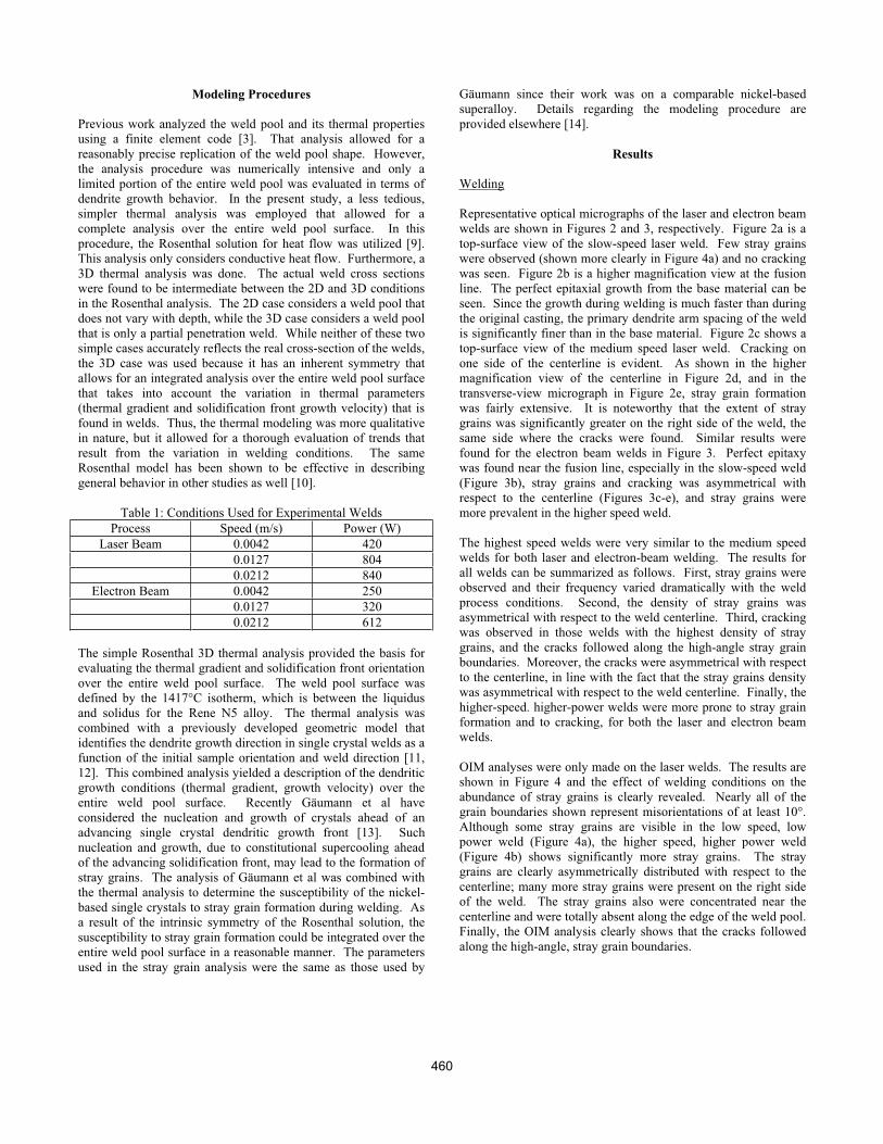
welds are shown in Figures 2 and 3, respectively. Figure 2a is a
top-surface view of the slow-speed laser weld. Few stray grains
were observed (shown more clearly in Figure 4a) and no cracking
was seen. Figure 2b is a higher magnification view at the fusion
line. The perfect epitaxial growth from the base material can be
seen. Since the growth during welding is much faster than during
the original casting, the primary dendrite arm spacing of the weld
is significantly finer than in the base material. Figure 2c shows a
top-surface view of the medium speed laser weld. Cracking on
one side of the centerline is evident. As shown in the higher
magnification view of the centerline in Figure 2d, and in the
transverse-view micrograph in Figure 2e, stray grain formation
was fairly extensive. It is noteworthy that the extent of stray
grains was significantly greater on the right side of the weld, the
same side where the cracks were found. Similar results were
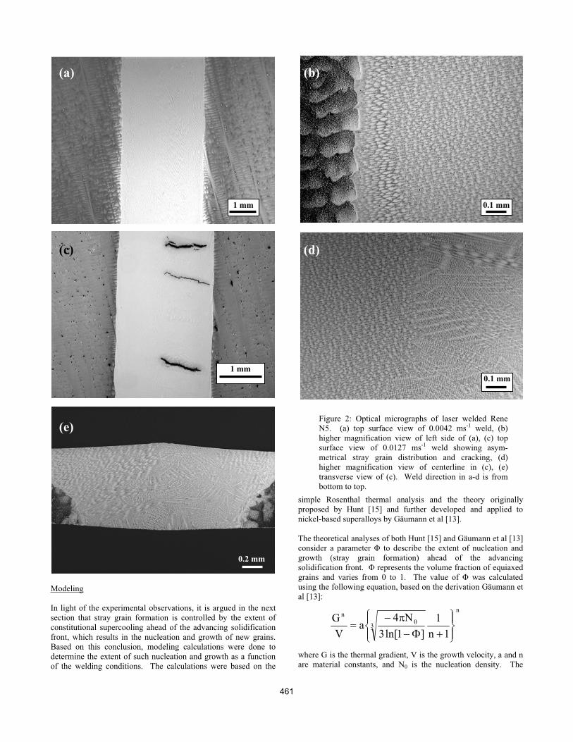
found for the electron beam welds in Figure 3. Perfect epitaxy
was found near the fusion line, especially in the slow-speed weld
(Figure 3b), stray grains and cracking was asymmetrical with
respect to the centerline (Figures 3c-e), and stray grains were
more prevalent in the higher speed weld.
The highest speed welds were very similar to the medium speed
welds for both laser and electron-beam welding. The results for
all welds can be summarized as follows. First, stray grains were
observed and their frequency varied dramatically with the weld
process conditions. Second, the density of stray grains was
asymmetrical with respect to the weld centerline. Third, cracking
was observed in those welds with the highest density of stray
grains, and the cracks followed along the high-angle stray grain
boundaries. Moreover, the cracks were asymmetrical with respect
to the centerline, in line with the fact that the stray grains density
was asymmetrical with respect to the weld centerline. Finally, the
higher-speed. higher-power welds were more prone to stray grain
formation and to cracking, for both the laser and electron beam
welds.
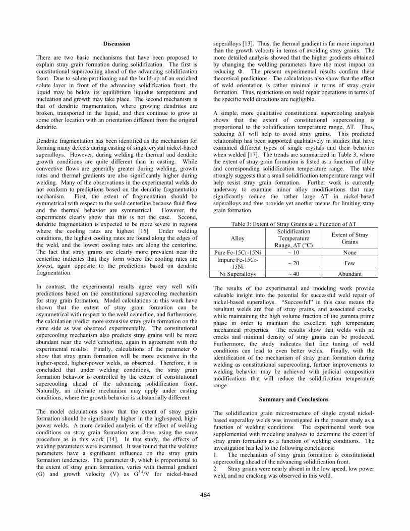
OIM analyses were only made on the laser welds. The results are
shown in Figure 4 and the effect of welding conditions on the
abundance of stray grains is clearly revealed. Nearly all of the
grain boundaries shown represent misorientations of at least 10°.
Although some stray grains are visible in the low speed, low
power weld (Figure 4a), the higher speed, higher power weld
(Figure 4b) shows significantly more stray grains. The stray
grains are clearly asymmetrically distributed with respect to the
centerline; many more stray grains were present on the right side
of the weld. The stray grains also were concentrated near the
centerline and were totally absent along the edge of the weld pool.
Finally, the OIM analysis clearly shows that the cracks followed
along the high-angle, stray grain boundaries.
460
n
30
n
1n
1
]1ln[3
N4a
V
G
Modeling
In light of the experimental observations, it is argued in the next
section that stray grain formation is controlled by the extent of
constitutional supercooling ahead of the advancing solidification
front, which results in the nucleation and growth of new grains.
Based on this conclusion, modeling calculations were done to
determine the extent of such nucleation and growth as a function
of the welding conditions. The calculations were based on the
simple Rosenthal thermal analysis and the theory originally
proposed by Hunt [15] and further developed and applied to
nickel-based superalloys by Gäumann et al [13].
The theoretical analyses of both Hunt [15] and Gäumann et al [13]
consider a parameter to describe the extent of nucleation and
growth (stray grain formation) ahead of the advancing
solidification front. represents the volume fraction of equiaxed
grains and varies from 0 to 1. The value of was calculated
using the following equation, based on the derivation Gäumann et
al [13]:
where G is the thermal gradient, V is the growth velocity, a and n
are material constants, and N0 is the nucleation density. The
Figure 2: Optical micrographs of laser welded Rene
N5. (a) top surface view of 0.0042 ms-1 weld, (b)
higher magnification view of left side of (a), (c) top
surface view of 0.0127 ms-1 weld showing asym-
metrical stray grain distribution and cracking, (d)
higher magnification view of centerline in (c), (e)
transverse view of (c). Weld direction in a-d is from
bottom to top.
(a) (b)
(c) (d)
(e)
1 mm
1 mm
0.2 mm
0.1 mm
0.1 mm
461
values for the three constants (a = 1.25 x 10⁶ sK3.4m-1, n = 3.4, and
N0 = 2 x 10¹⁵ m-3) were the same as those used by Gäumann for a
similar nickel-based superalloy [13].
The equation is derived by considering the nucleation and growth
of new crystals in the constitutionally supercooled region
immediately ahead of the growing dendrites. In the derivation,
the constitutional supercooling is given by the approximation T=
(aV)1/n where a, V, and n have the same meaning as before. The
derivation neglects curvature and thermal undercooling, which are
small with respect to the constitutional undercooling. The
nucleation undercooling is also ignored, which is assumed to be
valid for high gradient conditions as those found under welding
conditions [13].
When constitutional supercooling is minimal, = 0 and no new
grains form, yielding a weld microstructure that is free of stray
grains and maintains is single crystal nature. When = 1, the
solidification is 100% equiaxed in nature. The critical value of
corresponding to a stray grain free microstructure was
hypothesized to be 0.06 [13,15]. In the present work, rather than
define a single critical value of , an overall average value of
( AV), integrated over the entire weld pool solidification front,
was evaluated and the variation of AV as a function of welding
conditions was determined. This approach is considered to be
preferred to the use of a critical value since the analysis includes
Figure 3: Optical micrographs of electron beam welded
Rene N5. (a) top surface view of 0.0042 ms-1 weld, (b)
higher magnification view of left side of (a), (c) top
surface view of 0.0127 ms-1 weld showing asym-
metrical stray grain distribution and cracking, (d)
higher magnification view of centerline in (c), (e)
transverse view of (c). Weld direction in a-d is from
bottom to top.
(a) (b)
(c) (d)
(e)
1 mm
1 mm
0.2 mm
0.1 mm
0.1 mm
462
several parameters that are not well-known, and the calculated
absolute values for may not be accurate. Regardless of the
accuracy of the absolute value of , the changes in AV as a
function of changing conditions should be reliable.
When calculating as a function of position, it is assumed that
the dendritic growth is epitaxial with respect to the base material.
Six possible dendrite growth variants are possible, corresponding
to the six variants of the preferred [100] growth directions. All
six possible growth direction variants are considered at each
location. The growth direction that is selected at any given
location is the one that is best aligned with the thermal gradient at
that location, since this corresponds to a dendrite orientation with
the minimum undercooling and the minimum growth velocity
[11].
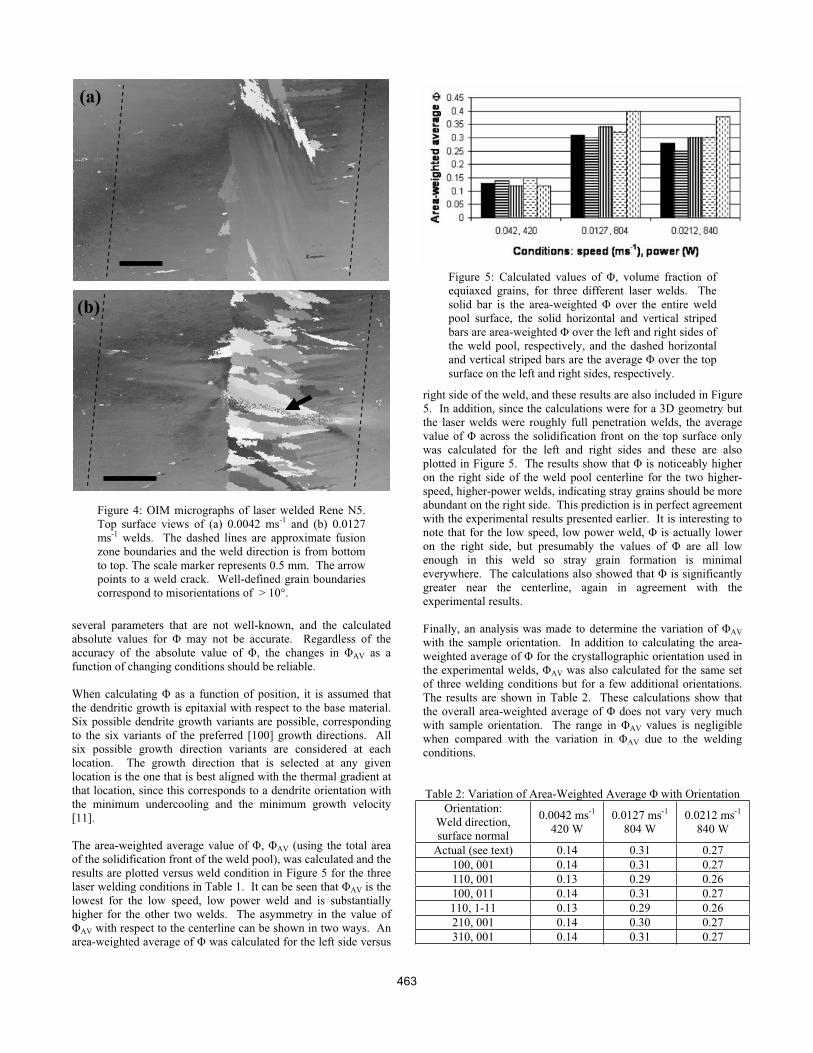
The area-weighted average value of , AV (using the total area
of the solidification front of the weld pool), was calculated and the
results are plotted versus weld condition in Figure 5 for the three
laser welding conditions in Table 1. It can be seen that AV is the
lowest for the low speed, low power weld and is substantially
higher for the other two welds. The asymmetry in the value of
AV with respect to the centerline can be shown in two ways. An
area-weighted average of was calculated for the left side versus
right side of the weld, and these results are also included in Figure
5. In addition, since the calculations were for a 3D geometry but
the laser welds were roughly full penetration welds, the average
value of across the solidification front on the top surface only
was calculated for the left and right sides and these are also
plotted in Figure 5. The results show that is noticeably higher
on the right side of the weld pool centerline for the two higher-
speed, higher-power welds, indicating stray grains should be more
abundant on the right side. This prediction is in perfect agreement
with the experimental results presented earlier. It is interesting to
note that for the low speed, low power weld, is actually lower
on the right side, but presumably the values of are all low
enough in this weld so stray grain formation is minimal
everywhere. The calculations also showed that is significantly
greater near the centerline, again in agreement with the
experimental results.
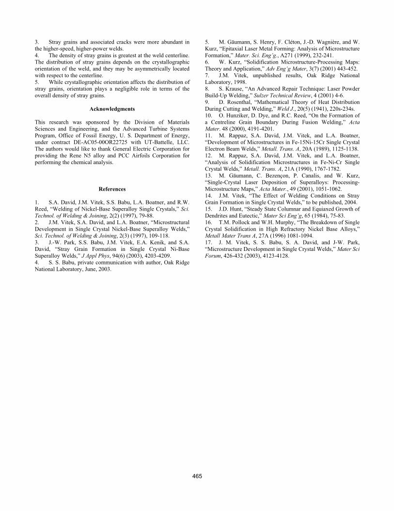
Finally, an analysis was made to determine the variation of AV
with the sample orientation. In addition to calculating the area-
weighted average of for the crystallographic orientation used in
the experimental welds, AV was also calculated for the same set
of three welding conditions but for a few additional orientations.
The results are shown in Table 2. These calculations show that
the overall area-weighted average of does not vary very much
with sample orientation. The range in AV values is negligible
when compared with the variation in AV due to the welding
conditions.
Table 2: Variation of Area-Weighted Average with Orientation
Orientation:
Weld direction,
surface normal
0.0042 ms-1
420 W
0.0127 ms-1
804 W
0.0212 ms-1
840 W
Actual (see text) 0.14 0.31 0.27
100, 001 0.14 0.31 0.27
110, 001 0.13 0.29 0.26
100, 011 0.14 0.31 0.27
110, 1-11 0.13 0.29 0.26
210, 001 0.14 0.30 0.27
310, 001 0.14 0.31 0.27
(a)
(b)
Figure 4: OIM micrographs of laser welded Rene N5.
Top surface views of (a) 0.0042 ms-1 and (b) 0.0127
ms-1 welds. The dashed lines are approximate fusion
zone boundaries and the weld direction is from bottom
to top. The scale marker represents 0.5 mm. The arrow
points to a weld crack. Well-defined grain boundaries
correspond to misorientations of > 10°.
Figure 5: Calculated values of , volume fraction of
equiaxed grains, for three different laser welds. The
solid bar is the area-weighted over the entire weld
pool surface, the solid horizontal and vertical striped
bars are area-weighted over the left and right sides of
the weld pool, respectively, and the dashed horizontal
and vertical striped bars are the average over the top
surface on the left and right sides, respectively.
463
Discussion
There are two basic mechanisms that have been proposed to
explain stray grain formation during solidification. The first is
constitutional supercooling ahead of the advancing solidification
front. Due to solute partitioning and the build-up of an enriched
solute layer in front of the advancing solidification front, the
liquid may be below its equilibrium liquidus temperature and
nucleation and growth may take place. The second mechanism is
that of dendrite fragmentation, where growing dendrites are
broken, transported in the liquid, and then continue to grow at
some other location with an orientation different from the original
dendrite.
Dendrite fragmentation has been identified as the mechanism for
forming many defects during casting of single crystal nickel-based
superalloys. However, during welding the thermal and dendrite
growth conditions are quite different than in casting. While
convective flows are generally greater during welding, growth
rates and thermal gradients are also significantly higher during
welding. Many of the observations in the experimental welds do
not conform to predictions based on the dendrite fragmentation
mechanism. First, the extent of fragmentation should be
symmetrical with respect to the weld centerline because fluid flow
and the thermal behavior are symmetrical. However, the
experiments clearly show that this is not the case. Second,
dendrite fragmentation is expected to be more severe in regions
where the cooling rates are highest [16]. Under welding
conditions, the highest cooling rates are found along the edges of
the weld, and the lowest cooling rates are along the centerline.
The fact that stray grains are clearly more prevalent near the
centerline indicates that they form where the cooling rates are
lowest, again opposite to the predictions based on dendrite
fragmentation.
In contrast, the experimental results agree very well with
predictions based on the constitutional supercooling mechanism
for stray grain formation. Model calculations in this work have
shown that the extent of stray grain formation can be
asymmetrical with respect to the weld centerline, and furthermore,
the calculation predict more extensive stray grain formation on the
same side as was observed experimentally. The constitutional
supercooling mechanism also predicts stray grains will be more
abundant near the weld centerline, again in agreement with the
experimental results. Finally, calculations of the parameter
show that stray grain formation will be more extensive in the
higher-speed, higher-power welds, as observed. Therefore, it is
concluded that under welding conditions, the stray grain
formation behavior is controlled by the extent of constitutional
supercooling ahead of the advancing solidification front.
Naturally, an alternate mechanism may apply under casting
conditions, where the growth behavior is substantially different.
The model calculations show that the extent of stray grain
formation should be significantly higher in the high-speed, high-
power welds. A more detailed analysis of the effect of welding
conditions on stray grain formation was done, using the same
procedure as in this work [14]. In that study, the effects of
welding parameters were examined. It was found that the welding
parameters have a significant influence on the stray grain
formation tendencies. The parameter , which is proportional to
the extent of stray grain formation, varies with thermal gradient
(G) and growth velocity (V) as G3.4/V for nickel-based
superalloys [13]. Thus, the thermal gradient is far more important
than the growth velocity in terms of avoiding stray grains. The
more detailed analysis showed that the higher gradients obtained
by changing the welding parameters have the most impact on
reducing . The present experimental results confirm these
theoretical predictions. The calculations also show that the effect
of weld orientation is rather minimal in terms of stray grain
formation. Thus, restrictions on weld repair operations in terms of
the specific weld directions are negligible.
A simple, more qualitative constitutional supercooling analysis
shows that the extent of constitutional supercooling is
proportional to the solidification temperature range, T. Thus,
reducing T will help to avoid stray grains. This predicted
relationship has been supported qualitatively in studies that have
examined different types of single crystals and their behavior
when welded [17]. The trends are summarized in Table 3, where
the extent of stray grain formation is listed as a function of alloy
and corresponding solidification temperature range. The table
strongly suggests that a small solidification temperature range will
help resist stray grain formation. Further work is currently
underway to examine minor alloy modifications that may
significantly reduce the rather large T in nickel-based
superalloys and thus provide yet another means for limiting stray
grain formation.
Table 3: Extent of Stray Grains as a Function of T
Alloy
Solidification
Temperature
Range, T (°C)
Extent of Stray
Grains
Pure Fe-15Cr-15Ni ~ 10 None
Impure Fe-15Cr-
15Ni~ 20 Few
Ni Superalloys ~ 40 Abundant
The results of the experimental and modeling work provide
valuable insight into the potential for successful weld repair of
nickel-based superalloys. “Successful” in this case means the
resultant welds are free of stray grains, and associated cracks,
while maintaining the high volume fraction of the gamma prime
phase in order to maintain the excellent high temperature
mechanical properties. The results show that welds with no
cracks and minimal density of stray grains can be produced.
Furthermore, the study indicates that fine tuning of weld
conditions can lead to even better welds. Finally, with the
identification of the mechanism of stray grain formation during
welding as constitutional supercooling, further improvements to
welding behavior may be achieved with judicial composition
modifications that will reduce the solidification temperature
range.
Summary and Conclusions
The solidification grain microstructure of single crystal nickel-
based superalloy welds was investigated in the present study as a
function of welding conditions. The experimental work was
supplemented with modeling analyses to determine the extent of
stray grain formation as a function of welding conditions. The
investigation has led to the following conclusions:
1. The mechanism of stray grain formation is constitutional
supercooling ahead of the advancing solidification front.
2. Stray grains were nearly absent in the low speed, low power
weld, and no cracking was observed in this weld.
464
3. Stray grains and associated cracks were more abundant in
the higher-speed, higher-power welds.
4. The density of stray grains is greatest at the weld centerline.
The distribution of stray grains depends on the crystallographic
orientation of the weld, and they may be asymmetrically located
with respect to the centerline.
5. While crystallographic orientation affects the distribution of
stray grains, orientation plays a negligible role in terms of the
overall density of stray grains.
Acknowledgments
This research was sponsored by the Division of Materials
Sciences and Engineering, and the Advanced Turbine Systems
Program, Office of Fossil Energy, U. S. Department of Energy,
under contract DE-AC05-00OR22725 with UT-Battelle, LLC.
The authors would like to thank General Electric Corporation for
providing the Rene N5 alloy and PCC Airfoils Corporation for
performing the chemical analysis.
References
1. S.A. David, J.M. Vitek, S.S. Babu, L.A. Boatner, and R.W.
Reed, “Welding of Nickel-Base Superalloy Single Crystals,” Sci.
Technol. of Welding & Joining, 2(2) (1997), 79-88.
2. J.M. Vitek, S.A. David, and L.A. Boatner, “Microstructural
Development in Single Crystal Nickel-Base Superalloy Welds,”
Sci. Technol. of Welding & Joining, 2(3) (1997), 109-118.
3. J.-W. Park, S.S. Babu, J.M. Vitek, E.A. Kenik, and S.A.
David, “Stray Grain Formation in Single Crystal Ni-Base
Superalloy Welds,” J Appl Phys, 94(6) (2003), 4203-4209.
4. S. S. Babu, private communication with author, Oak Ridge
National Laboratory, June, 2003.
5. M. Gäumann, S. Henry, F. Cléton, J.-D. Wagnière, and W.
Kurz, “Epitaxial Laser Metal Forming: Analysis of Microstructure
Formation,” Mater. Sci. Eng’g., A271 (1999), 232-241.
6. W. Kurz, “Solidification Microstructure-Processing Maps:
Theory and Application,” Adv Eng’g Mater, 3(7) (2001) 443-452.
7. J.M. Vitek, unpublished results, Oak Ridge National
Laboratory, 1998.
8. S. Krause, “An Advanced Repair Technique: Laser Powder
Build-Up Welding,” Sulzer Technical Review, 4 (2001) 4-6.
9. D. Rosenthal, “Mathematical Theory of Heat Distribution
During Cutting and Welding,” Weld J., 20(5) (1941), 220s-234s.
10. O. Hunziker, D. Dye, and R.C. Reed, “On the Formation of
a Centreline Grain Boundary During Fusion Welding,” Acta
Mater. 48 (2000), 4191-4201.
11. M. Rappaz, S.A. David, J.M. Vitek, and L.A. Boatner,
“Development of Microstructures in Fe-15Ni-15Cr Single Crystal
Electron Beam Welds,” Metall. Trans. A, 20A (1989), 1125-1138.
12. M. Rappaz, S.A. David, J.M. Vitek, and L.A. Boatner,
“Analysis of Solidification Microstructures in Fe-Ni-Cr Single
Crystal Welds,” Metall. Trans. A, 21A (1990), 1767-1782.
13. M. Gäumann, C. Bezençon, P. Canalis, and W. Kurz,
“Single-Crystal Laser Deposition of Superalloys: Processing-
Microstructure Maps,” Acta Mater., 49 (2001), 1051-1062.
14. J.M. Vitek, “The Effect of Welding Conditions on Stray
Grain Formation in Single Crystal Welds,” to be published, 2004.
15. J.D. Hunt, “Steady State Columnar and Equiaxed Growth of
Dendrites and Eutectic,” Mater Sci Eng’g, 65 (1984), 75-83.
16. T.M. Pollock and W.H. Murphy, “The Breakdown of Single
Crystal Solidification in High Refractory Nickel Base Alloys,”
Metall Mater Trans A, 27A (1996) 1081-1094.
17. J. M. Vitek, S. S. Babu, S. A. David, and J-W. Park,
“Microstructure Development in Single Crystal Welds,” Mater Sci
Forum, 426-432 (2003), 4123-4128.
465