
Second Generation HTS Wire for Electric Power …KEPRI+EPRI...superior performance. powerful...
19
superior performance. powerful technology. SuperPower, Inc. is a subsidiary of Royal Philips Electronics N.V. Second Generation HTS Wire for Electric Power Applications Yi-Yuan Xie, D. Hazelton, J.C. Llambes, Y. Chen, X. Xiong, A. Rar, K. Lenseth, Y. Qiao, A. Knoll J. Dackow, and V. Selvamanickam 2009 KEPRI-EPRI Joint Superconductivity Conference, Nov 16-19, Daejeon, South Korea
Transcript of Second Generation HTS Wire for Electric Power …KEPRI+EPRI...superior performance. powerful...

superior performance.powerful technology.
SuperPower, Inc. is a subsidiary of Royal Philips Electronics N.V.
Second Generation HTS Wire for Electric Power Applications
Yi-Yuan Xie, D. Hazelton, J.C. Llambes, Y. Chen, X. Xiong, A. Rar, K. Lenseth, Y. Qiao, A. Knoll J. Dackow, and V. Selvamanickam
2009 KEPRI-EPRI Joint Superconductivity Conference, Nov 16-19, Daejeon, South Korea
KEPRI-EPRI Joint Superconductivity Conference – November 16-18, 2009
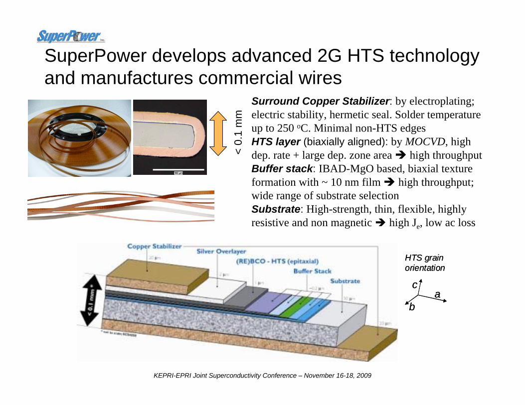
SuperPower develops advanced 2G HTS technology and manufactures commercial wires
< 0.
1 m
m
Surround Copper Stabilizer: by electroplating; electric stability, hermetic seal. Solder temperature up to 250 oC. Minimal non-HTS edgesHTS layer (biaxially aligned): by MOCVD, high dep. rate + large dep. zone area high throughputBuffer stack: IBAD-MgO based, biaxial texture formation with ~ 10 nm film high throughput; wide range of substrate selectionSubstrate: High-strength, thin, flexible, highly resistive and non magnetic high Je, low ac loss
b
ca
HTS grain orientation
b
ca
HTS grain orientation

KEPRI-EPRI Joint Superconductivity Conference – November 16-18, 2009
IBAD-MgO-based MOCVD 2G HTS wire is produced in kilometer lengths
3
• Minimum current (Ic) = 282 A/cm-w over 1065 m • 2009 new world record: Ic × Length = 300,330 A-m• Minimum current (Ic) = 282 A/cm-w over 1065 m • 2009 new world record: Ic × Length = 300,330 A-m
Kilometer Long 2G HTS Wires
0
50
100
150
200
250
300
350
400
450
0 100 200 300 400 500 600 700 800 900 1000 1100
Position (m)
I c (A
/cm
-w)
Jul-08Aug-08
Aug-09 • 77 K, Ic measured every 5 m using continuous dc currents over entire tape width of 12 mm (not slit)
• Voltage criterion: 0.2 microvolt/cm

KEPRI-EPRI Joint Superconductivity Conference – November 16-18, 2009
Albany HTS Cable Project • 350m long - 34.5kV - 800Arms - 48MVA• Cold dielectric, 3 phases-in-1 cryostat, stranded copper core design• Cooled with subcooled, pressurized LN2 operating at ~ 69K• Two Phases – Phase I - 320m + 30m BSCCO
– Phase II - 30m BSCCO replaced by 30m YBCO cable
Supported by Federal (DOE) and NY State (NYSERDA) Funds
Design, construct and operate the Cryogenic Refrigeration System, and provide overall cable remote monitoring and utility interface
Design, build, install, and test the HTS cable, terminations, & joint
Host utility, conventional cable & system protection, system impact studies
Project Manager; Site infrastructure, Manufacture of 2G HTS wire
Section of 30m 2G Cable in Phase II using ~ 10 km
SuperPower® 2G HTS Wire
KEPRI-EPRI Joint Superconductivity Conference – November 16-18, 2009
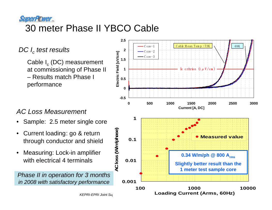
30 meter Phase II YBCO Cable
-0.5
0
0.5
1
1.5
2
2.5
0 500 1000 1500 2000 2500 3000Current [A, DC]
Elec
tric
Fiel
d [u
V/cm
]
C ore-1
C ore-2
C ore-3
Ic critrion (1μV/cm )
C able M ean Tem p : 73K 69K
Cable Ic (DC) measurement at commissioning of Phase II – Results match Phase I performance
0.001
0.01
0.1
1
100 1000 10000Loading Current (Arms, 60Hz)
AC lo
ss (W
/m/p
hase
)
Measured value
• Sample: 2.5 meter single core
• Current loading: go & return through conductor and shield
• Measuring: Lock-in amplifier with electrical 4 terminals
0.34 W/m/ph @ 800 Arms
Slightly better result than the 1 meter test sample core
AC Loss Measurement
DC Ic test results
Phase II in operation for 3 months in 2008 with satisfactory performance

KEPRI-EPRI Joint Superconductivity Conference – November 16-18, 2009
Excellent in-field performance makes a wide range of real-world applications possible
High Temp, Low Fields:• Cable• SFCL • Transformer • Motor/generator• Plasma Confinement• Xtal growth magnet• Magnetic separation
Medium Temp, Medium Fields:• Motor/generator• Plasma Confinement• Crystal Growth Magnet• Magnetic separation• Maglev• SMES
Low Temp, High Fields:• SMES• High-Field MRI• High-Field Insert• NMR
* Je is calculated based on Ic (77 K, 0T) = 100 A/4 mm (surr. copper stabilized) and scaling factors measured by D. Larbalestier, et al at FSU and E. Barzi, et al. of Fermi Lab.
0 5 10 15 20 25 30 350.025
0.25
2.5
25
250
1E-3
0.01
0.1
1
10
I c(B)/I
c(77K
,0T)
J e (KA
/cm
2 )
Magnetic Field B (Tesla)
Ic(B//ab)/Ic(77K,0T) - 4.2K Ic(B//c)/Ic(77K,0T) - 4.2 K Ic(B//c)/Ic(77K,0T) - 14 K Ic(B//c)/Ic(77K,0T) - 22 K Ic(B//c)/Ic(77K,0T) - 33K Ic(B//c)/Ic(77K,0T) - 50K Ic(B//c)/Ic(77K,0T) - 65 K Ic(B//c)/Ic(77K,0T) - 72K Ic(B//c)/Ic(77K,0T) - 77K
Low Field
High Field Ultra-High Field
Medium
Field

KEPRI-EPRI Joint Superconductivity Conference – November 16-18, 2009
2008: Zr doping was demonstrated in MOCVD to achieve dramatic improvements in in-field performance
Data from Y. Zhang, M. Paranthaman, A. Goyal, ORNL
150
200
250
300
350
400
450
500
550
-20 0 20 40 60 80 100 120Angle (deg)
2007: 2.8 μm (GdY)BCO
2008: 3.15 μm Zr:(GdY)BCO
2008: 3.33 μm Zr:(GdY)BCO
• 67% increase in minimum Ic to 267 A/cm corresponds to Je of 41,000 A/cm2 (no copper)
• 88% increase in Ic (B ⊥ tape) to 340 A/cm corresponds to Je of 52,300 A/cm2 (no copper)
• 97% increase in minimum Ic to 186 A/cm corresponds to Je of 28,500 A/cm2 (no copper)
• 85% increase in Ic (B ⊥ tape) to 229 A/cm corresponds to Je of 35,200 A/cm2 (no copper)
65 K, 3 T
In 2009, Zr-doping chemistry successfully transferred to production line
77K, 1 T
050
100150200250300350400450
-20 0 20 40 60 80 100 120Angle between field and tape (degrees)
Ic (A
/cm
)
3.5 micron SmYBCO2.8 micron GdYBCO
3.3 micron Zr:GdYBCO
Selvamanickam, Xie and Dackow, 2009 DOE HTS Program Review
KEPRI-EPRI Joint Superconductivity Conference – November 16-18, 2009
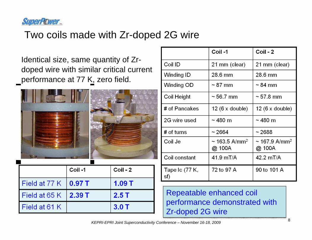
Two coils made with Zr-doped 2G wire
Identical size, same quantity of Zr-doped wire with similar critical current performance at 77 K, zero field.
8
Repeatable enhanced coil performance demonstrated with Zr-doped 2G wire
Repeatable enhanced coil performance demonstrated with Zr-doped 2G wire

KEPRI-EPRI Joint Superconductivity Conference – November 16-18, 2009
Zr doping provides enhanced performance in nitrogen cooling
2.4363.8
3.0860
2.9561
2.6763.2
2.4765
1.4373.8
2007
2008
2009
2.3964.5
0.7377
2.2665.8
1.8470.3
0.9577.4
1.0977.3
B0 (T)T (K)
0.0
0.5
1.0
1.5
2.0
2.5
3.0
3.5
4.0
55 60 65 70 75 80
Temperature (K)
Cen
tral
Fie
ld, B
o (T
)
2007 Coil 2008 Coil 2009 Coil
SN2:LN2 boundary Linear (2009 Coil) Linear (2008 Coil)
SN2
LN2
2007 Coil with (SmY)BCO wire
2008 & 2009 coils withZr:(GdY)BCO wire
30%
• 30% higher field in coils with made with Zr-doped chemistry• 2008 and 2009 coils have larger winding I.D. and lower coil constant

KEPRI-EPRI Joint Superconductivity Conference – November 16-18, 2009
2009 high field insert coil achieves record performance
10
Coil ID 12.7 mm (clear)Winding ID 19.1 mmWinding OD ~ 84 mmCoil Height ~ 73.6 mm# of Pancakes 16 (8 x double)2G wire used ~ 600 m# of turns ~ 3696Coil Je ~155.3 A/mm2 @
100ACoil constant ~ 51.8 mT/AWire Ic (77 K, sf) 120 A – 180 A
(non Zr-doping)
Insert coil tested in NHMFL’sunique, 20 T, 20 cm wide-bore, Bitter magnet
Patrick Noyes, Ulf Trociewitz, HuubWeijers,Denis Markewicz, David Larbalestier 19.89
27.427.410.410.4
4.2
3.0
4.604.602.492.49
65
1.0
1.931.931.391.39
77
Total Central Field – in background field (axial) (T)
Temperature (K)Central field – self field (T)
With Background field (T)

KEPRI-EPRI Joint Superconductivity Conference – November 16-18, 2009
HTS generator project
• Funded by US Office of Naval Research (ONR)• Target operation: 36.5 MVA • Partners: SuperPower, Baldor Electric, General Dynamics-Electric Boat,
Naval Surface Warfare Center (Philadelphia), Naval Research Lab,Oak Ridge National Lab
• Current Phase: Conceptual design / risk reduction studies– Smaller / lighter weight tradeoff studies vs. efficiency vs. cost– HTS windings development– Rotor / stator design / development– Fabrication of test articles

KEPRI-EPRI Joint Superconductivity Conference – November 16-18, 2009
2G HTS coil for thermal cycle testing at NRLTe
rmin
al B
lock
s
• Model Coil 1: ~ 250 mm x 150 mm• 250 m of 4 mm wide 2G HTS wire

KEPRI-EPRI Joint Superconductivity Conference – November 16-18, 2009
0 2000 4000 6000 8000 10000 12000Time [sec]
Coi
l Vol
tage
50%80%
90%
95%100%
105%110%
115%
120%(b) Typical Voltage vs Time Curves
Various currents as a percentageof the quench instability current
(b) Typical voltage-time curves for the same HTS coil. For each value of current, the voltage is monitored for some period of time to determine if it is stable. The highest current at which the voltage exhibits long term stability is designated the quench instability limit current.
NRL test results: Quench stability
Data from R. Holtz, NRL
KEPRI-EPRI Joint Superconductivity Conference – November 16-18, 2009
-100
-80
-60
-40
-20
0
20
40
60
80
0 20 40 60 80 100
Time [ms]
Cur
rent
[kA
]
-2.0
-1.0
0.0
1.0
2.0
3.0
4.0
5.0
6.0
7.0
Volta
ge a
cros
s H
TS
elem
ents
[kV]
Iprospective I_total_KEMA I_HTS Ish V_total_KEMA
-5.0-4.0
-3.0-2.0-1.00.0
1.02.03.0
4.05.0
2 4 6 8 10 12 14 16 18 20
Time [ms]
Cur
rent
[kA
]
-1.0-0.5
0.00.51.01.5
2.02.53.0
3.54.0
Volta
ge a
cros
s H
TS
elem
ents
[kV]
I_total_KEMA I_HTS Ish V_total_KEMA
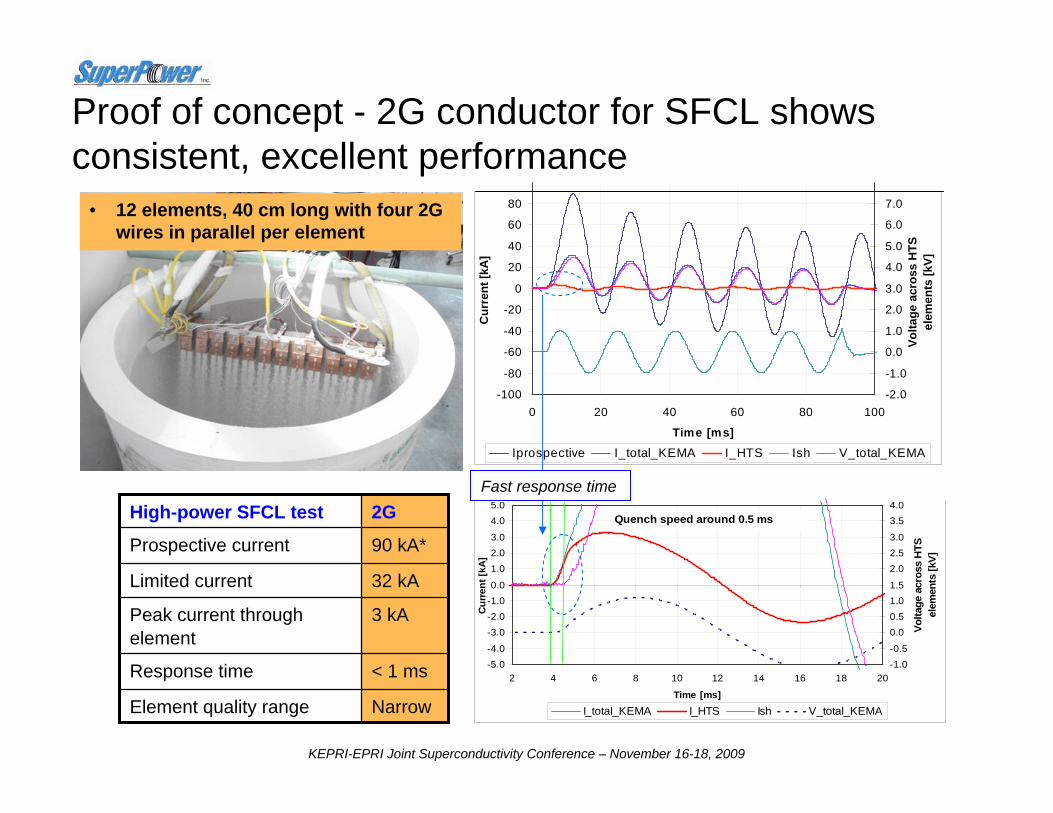
Quench speed around 0.5 ms
Proof of concept - 2G conductor for SFCL shows consistent, excellent performance
< 1 msResponse time
3 kAPeak current through element
90 kA*Prospective current
32 kALimited current
NarrowElement quality range
2G High-power SFCL test
• 12 elements, 40 cm long with four 2G wires in parallel per element
Fast response time

KEPRI-EPRI Joint Superconductivity Conference – November 16-18, 2009
SFCL modular system design – components integration
2G tape – Jc, J/cm/tape, RUL Arms/tape, mechanical, thermal and electrical properties
Shunt Coils – Zsh = Rsh + jXsh, X/R ratio, EM force withstand, thermal and electrical properties, connectors, size, weight, over-banding, ease of assembly and manufacturablity
HTS assembly – Tape per element, RUL per element, element energy capability, connectors, size, cooling orientation, failure mechanisms and mitigation, losses and their effects on cryogenics design
HV design – LN2 and GN2 design stress criteria, spacing between tapes, elements and modules, stress shield dimensions, using solid barriers or not, bushings and assembly integration, assembly supporting structure (post insulators), overall assembly to cryostat spacing and integration
Cryogenics - LN2 flow control, LN2 and GN2 interface, pressurizing, safety issues, thermal handling of fault and steady state losses
Systems issues - SFCL device testing, systems study and utility interfaces
Instrumentation, control and condition monitoring of SFCL system
Complete Transmission / Distribution System Design Boundaries
Module Design Specification and Criteria

KEPRI-EPRI Joint Superconductivity Conference – November 16-18, 2009
2G modular RUL capabilities tested at FSU-CAPS
Test conditions evaluated:
• 2 SFCL tapes configurations (“standard” and new configuration) are evaluated with 2 types of modules
• Follows AEP sequence
• Module current scalable in multiples of 500 A peak
• Module voltage scalable from 400 V - 1 kV peak
• Prospective fault currents scalable from 5 - 10 kA peak
Photo of 4 modules in test dewar ready for test

KEPRI-EPRI Joint Superconductivity Conference – November 16-18, 2009
3 x Base-Line Voltage
RUL vs. Fault Duration / Occurrence.
KEPRI-EPRI Joint Superconductivity Conference – November 16-18, 2009
Summary
• SuperPower routinely produces 2G HTS wire in a manufacturing line. New 2009 world record performance of Ic×L = 300,330 A-m achieved in km long wires.
• Albany Cable Project – World’s first in-grid 2G HTS device demonstrated the suitability of SuperPower® 2G wire for power cable and low ac loss.
• In-field performance enhancement at all field angles achieved via Zr-doping; technology has been transferred into production line
• High-field coils with consistently improved performance demonstrated with SuperPower® 2G wire. Self field was increased from 0.73 Tesla to above 1 T at 77 K and more than 2 T at 65 K. At 4.2 K, maximum fields of 10.4 T and 27.4 T were achieved in self-field and with 19.9 T background, respectively
• Model coils for HTS generator fabricated and demonstrated reliable performance
• Proof-of-concept for resistive 2G SFCL demonstrated. Developed generalized SFCL module specification:
– Module current scalable in multiples of 500 A peak – Module voltage scalable from 400 V - 1 kV peak– Prospective fault currents scalable from 5 - 10 kA peak

KEPRI-EPRI Joint Superconductivity Conference – November 16-18, 2009
Questions?
Thank you for your interest!
For further information about SuperPower, please visit: www.superpower-inc.com
or e-mail: [email protected]


