Seamless Replacement of a DCS in a Large Wastewater Treatment Plant...
13
2013 ISA Water / Wastewater and Automatic Controls Symposium Aug 6-8, 2013 – Orlando, Florida, USA – www.isawwsymposium.com Seamless Replacement of a DCS in a Large Wastewater Treatment Plant: Lessons Learned from the City of Fort Worth Village Creek Water Reclamation Plant Nathan Mogaru, P.E. 1 *, John Robinson 2 , Luke Matus 3 1 CDM Smith, 8140 Walnut Hill Lane Suite 1000, Dallas, TX 76011 (*[email protected], Office: 214-346-2800, Cell: 817-501-6939) 2 CDM Smith, 8140 Walnut Hill Lane Suite 1000, Dallas, TX 76011 3 City of Fort Worth Village Creek WRF, 4500 Wilma Lane, Arlington, TX 76012 KEYWORDS DCS Replacement, Maintenance of Plant Operations (MOPO), Operator Acceptance, Documentation, Legacy Control System ABSTRACT Distributed Control Systems (DCSs) installed in the late 1980’s and early 1990’s have either been incrementally updated over the years or are long due for replacement, depending on the particular DCS product in question. Although the proprietary real-time operating system and programmed algorithms of a legacy DCS may work just fine, the hardware (controllers, workstations, servers, and network components) and general purpose operating systems (UNIX, Windows) that interact with them are likely beyond their commercial lifespan and are no longer supported. Unlike facilities which have regularly scheduled shutdowns that can provide an opportunity for full replacement of a DCS, a wastewater treatment plant runs 24 hours a day, seven days a week, and must meet permit requirements for effluent quality. There are four major areas that must be addressed in order to achieve a successful replacement of a DCS in a wastewater treatment plant; compliance with local, state, and federal regulations, operator acceptance of the modern DCS, stable and seamless transition of process control functionality, and comprehensive documentation. This paper is a case study on how the four mentioned areas were successfully addressed for the replacement of a DCS in a large North Texas wastewater treatment plant. The project included DCS replacement, control room remodel, and update of the control area electrical infrastructure in the midst of other ongoing construction projects at the plant. Although the project involved replacement of a commercially obsolete proprietary DCS with a modern DCS (proprietary yes, but open to communication with other supplier components), many of the principles followed would apply to any effort to update a legacy control infrastructure. Mistakes and recovery activity will be discussed along with those items that executed as planned. Introduction The Village Creek Wastewater reclamation facility in Fort Worth Texas is a 166 MGD wastewater treatment facility featuring high rate clarification of influent, primary clarification, activated sludge processing, secondary clarification, digestion, and disinfection. The plant recently upgraded its facilities to permit use of digester and
-
Upload
dinhnguyet -
Category
Documents
-
view
218 -
download
2
Transcript of Seamless Replacement of a DCS in a Large Wastewater Treatment Plant...

2013 ISA Water / Wastewater and Automatic Controls Symposium
Aug 6-8, 2013 – Orlando, Florida, USA – www.isawwsymposium.com
Seamless Replacement of a DCS in a Large Wastewater Treatment
Plant: Lessons Learned from the City of Fort Worth Village Creek
Water Reclamation Plant
Nathan Mogaru, P.E.1*, John Robinson
2, Luke Matus
3
1CDM Smith, 8140 Walnut Hill Lane Suite 1000, Dallas, TX 76011
(*[email protected], Office: 214-346-2800, Cell: 817-501-6939) 2CDM Smith, 8140 Walnut Hill Lane Suite 1000, Dallas, TX 76011
3City of Fort Worth Village Creek WRF, 4500 Wilma Lane, Arlington, TX 76012
KEYWORDS
DCS Replacement, Maintenance of Plant Operations (MOPO), Operator Acceptance, Documentation, Legacy
Control System
ABSTRACT
Distributed Control Systems (DCSs) installed in the late 1980’s and early 1990’s have either been incrementally
updated over the years or are long due for replacement, depending on the particular DCS product in question.
Although the proprietary real-time operating system and programmed algorithms of a legacy DCS may work
just fine, the hardware (controllers, workstations, servers, and network components) and general purpose
operating systems (UNIX, Windows) that interact with them are likely beyond their commercial lifespan and
are no longer supported. Unlike facilities which have regularly scheduled shutdowns that can provide an
opportunity for full replacement of a DCS, a wastewater treatment plant runs 24 hours a day, seven days a
week, and must meet permit requirements for effluent quality. There are four major areas that must be
addressed in order to achieve a successful replacement of a DCS in a wastewater treatment plant; compliance
with local, state, and federal regulations, operator acceptance of the modern DCS, stable and seamless
transition of process control functionality, and comprehensive documentation.
This paper is a case study on how the four mentioned areas were successfully addressed for the replacement
of a DCS in a large North Texas wastewater treatment plant. The project included DCS replacement, control
room remodel, and update of the control area electrical infrastructure in the midst of other ongoing
construction projects at the plant. Although the project involved replacement of a commercially obsolete
proprietary DCS with a modern DCS (proprietary yes, but open to communication with other supplier
components), many of the principles followed would apply to any effort to update a legacy control
infrastructure. Mistakes and recovery activity will be discussed along with those items that executed as
planned.
Introduction
The Village Creek Wastewater reclamation facility in Fort Worth Texas is a 166 MGD wastewater treatment
facility featuring high rate clarification of influent, primary clarification, activated sludge processing, secondary
clarification, digestion, and disinfection. The plant recently upgraded its facilities to permit use of digester and
Mogaru, Robinson, Matus 2
2013 ISA Water / Wastewater and Automatic Controls Symposium
Aug 6-8, 2013 – Orlando, Florida, USA – www.isawwsymposium.com
landfill gas in a co-generation process that produces electrical power and steam for use in producing air for the
activated sludge basins. The plant has won numerous awards; most recently the plant won the U.S.
Environmental Protection Agency 2010 Sustainable Public Health Protection Award. Computerized process
control has been an integral part of Village Creek operations for over 35 years, and the plant has had three
generations of Distributed Control Systems (DCSs) installed from in the mid 1970’s to the present. This paper
discusses aspects of the most recent generation, the Emerson Ovation Distributed Control System (DCS)
commissioned in 2012. The paper discusses four areas that were addressed in the project to achieve the
successful replacement of the legacy DCS: compliance with local, state, and federal regulations; operator
acceptance of the new DCS; stable and seamless transition of process control functionality; and
comprehensive documentation.
The legacy DCS in operation prior to 2012 was a 1990’s XL/System (XL/S) DCS manufactured by Johnson-
Yokogawa. The XL/S was comprised of six controllers, known as Distributed Control Units (DCUs), a historical
server, database server, operator workstations, and network components. The system featured over 200 sheets
of Excel reports covering all aspects of plant operations, and having the built-in intelligence to flag
circumstances where there was missing laboratory data or there were unique configurations of flow for short
periods of time. Over the life of the XL/S, there have been several plant process upgrades that added or
modified control strategies. In addition, several projects at the plant featured stand-alone Programmable Logic
Controllers (PLCs) that were interfaced to the DCS system using Ethernet. Written documentation (in the XL/S
O&M manuals) of changes to the legacy DCS after initial installation are of mixed quality, with some
modifications being well documented and others being minimally documented.
Compliance with Local, State, and Federal Regulations
There are two aspects to regulatory compliance: meeting procurement regulations and meeting plant
operating requirements so as to be in compliance with all regulations. Meeting the various procurement
regulations in the execution of this project is a fascinating story but is outside of the scope of this paper.
Meeting plant operating requirements so that there were no permit violations was a major criterion in all
decisions associated with the project. Major decisions made once the particular DCS was chosen included:
1. Graphics and Control “look and feel” in the new DCS would be as near as possible to the “look and feel” of
the legacy DCS.
2. Control logic in the new DCS would be patterned as nearly as possible to the logic in the existing DCS, with
allowances for improvements in technology being offered in the new DCS.
3. Integrity of the data being sent to regulatory agencies was paramount. Reports would operate on the
legacy DCS until all points had been cut over to the new DCS. This meant that a portion of the annual
reporting cycle would utilize data residing in the legacy DCS and a portion would use data residing in the
new DCS for the year 2012. After migration of all the points to the new DCS, the owner will then backfill
data from the legacy DCS report into the new DCS report.
4. The plant would be transitioned to the new DCS in small segments that corresponded to specific processes,
or by PLC units, rather than by legacy DCS groupings. These segments could have control strategies in

Mogaru, Robinson, Matus 3
2013 ISA Water / Wastewater and Automatic Controls Symposium
Aug 6-8, 2013 – Orlando, Florida, USA – www.isawwsymposium.com
more than one DCS. The overall order of transition was presented in the Maintenance of Plant Operations
(MOPO) plan.
5. Overall process stability, rather than speed of actual signal wire transition to the new system, was the goal
of the transition plan. There were major physical relocations of process signals and marshalling locations
when the legacy system was installed in 1992, and the system it replaced had several failing components.
Therefore, the emphasis in 1992 was to move from the old system as quickly as possible, and fine-tune the
control later. In 2012, the legacy system was not in danger of failure, the overall quantity of controls on the
system was larger, wire relocation distances were minor, and efficient plant operations were strongly linked
to the robustness of the process control strategies. Therefore, in order to minimize the risk of a plant upset
leading to possible permit violations, it was decided that related process segments that had been
transitioned to the new DCS would be fully tuned before moving to the next process.
Operator Acceptance of the new DCS
The key concepts of operator acceptance revolved around maintaining as much as possible the “look and feel”
of the graphics, maintaining as much as possible similarity with the existing process control strategies. Operator
acceptance of the reporting tool and manual data entry for laboratory data was also needed. The five steps
taken in the application programming development to gain operator acceptance were: understanding the
legacy DCS control strategies, understanding of the historical reports, methodical graphics application
development, methodical controls application development, and careful application testing.
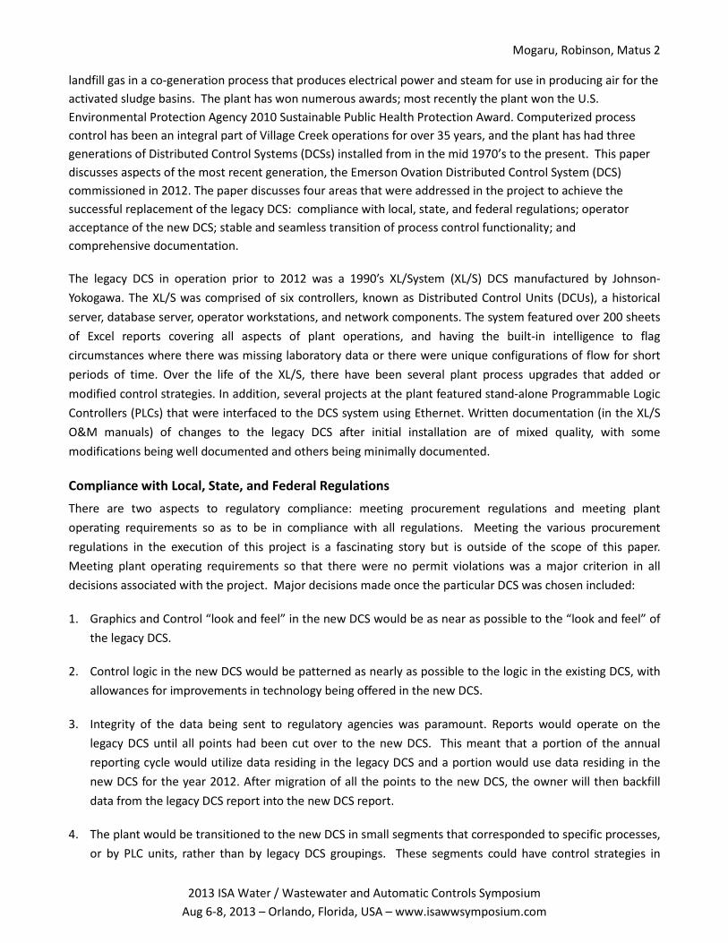
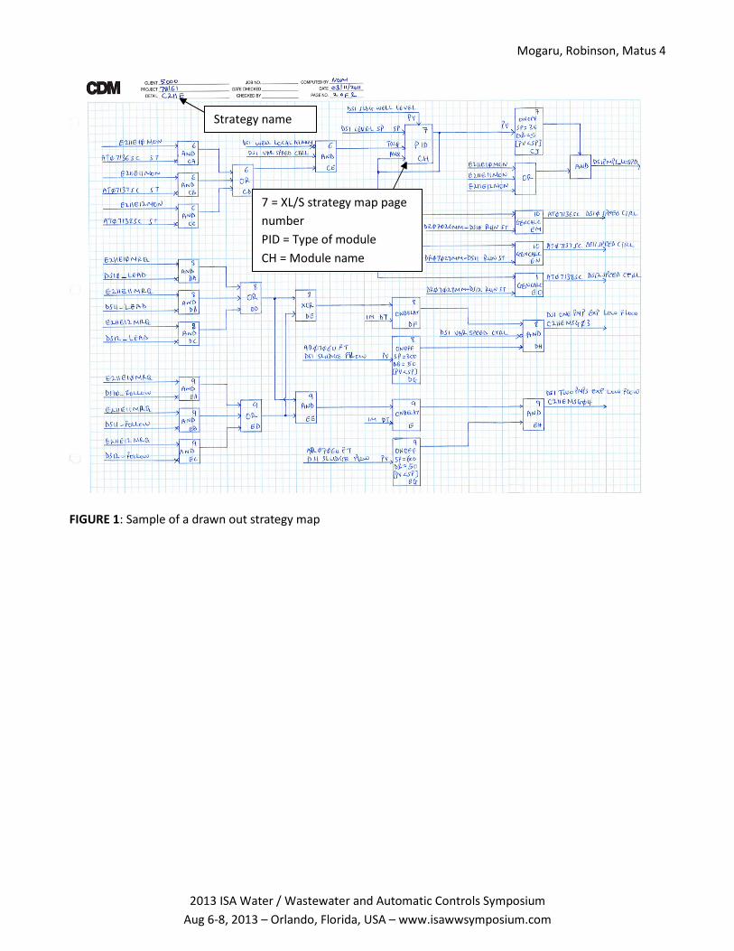
Deciphering Control Strategies and Preparing Control Narratives Submittal
While the legacy DCS did not support programming in any of the IEC languages, it did permit visualization of
the logic in standard function block-like diagrams called strategy maps. Each strategy map was the size of an
8.5" x 11" paper with a limited number of the modules fitting onto the map. It could be produced as a printed
sheet or PDF file. One process control strategy could span multiple strategy map pages. For the project team to
properly review the legacy DCS strategy maps, they were drawn out by hand on an 11x17 paper using
corresponding new DCS modules. This procedure consolidated multiple pages of the strategy maps into one
sheet and had the benefit of educating the developer in how the legacy strategy operated. The hand-drawn
maps facilitated easy review of the control strategies from the left (source registers) to the right (destination
registers). An example of a hand drawn map is shown in Figure 1. Legacy DCS sequencer modules were drawn
out using basic Boolean logic, arithmetic algorithms, and other control modules. An example of a sequencer
module is shown in Figure 2, with its corresponding representation in function block-like logic shown in Figure
3.
Mogaru, Robinson, Matus 4
2013 ISA Water / Wastewater and Automatic Controls Symposium
Aug 6-8, 2013 – Orlando, Florida, USA – www.isawwsymposium.com
FIGURE 1: Sample of a drawn out strategy map
7 = XL/S strategy map page
number
PID = Type of module
CH = Module name
Strategy name

Mogaru, Robinson, Matus 5
2013 ISA Water / Wastewater and Automatic Controls Symposium
Aug 6-8, 2013 – Orlando, Florida, USA – www.isawwsymposium.com
FIGURE 2: Legacy DCS Sequencer module
Figure 3: Sequencer module representation in function block diagrams
Mogaru, Robinson, Matus 6
2013 ISA Water / Wastewater and Automatic Controls Symposium
Aug 6-8, 2013 – Orlando, Florida, USA – www.isawwsymposium.com
The hand-drawn maps were thoroughly reviewed and compared to the existing control descriptions to make
sure any process upgrades and strategy updates were documented. Any discrepancy found was documented as
comments in the existing control descriptions. Tuning constants like timer presets, PID parameters, process
clamps, and other constants were also vetted and discrepancies documented. The final document was sent to
the owner as a controls description submittal for review.
After owner review, comment, and return of comments to the project team, face-to-face meetings were held
to discuss review comments and resolve discrepancies. After incorporating the owner feedback and comments
from the review meeting, the final control description narrative was completed. The replacement DCS was
programmed based on this final control description. During the programming phase (a period lasting over a
year), the owner maintained a strategy modification log to confirm that the new DCS incorporated any
modifications that occurred after approval of the final control narrative.
Historical Reports
The legacy DCS had about 300 pages of reports in Excel format. Each page was an independent spreadsheet
that collected raw data from the historical log. The initial step in duplicating the reports on the new system
involved documenting all existing reports by name and listing the database points used in each report. A
review document was put together listing each report and points associated with each report, and submitted
to the owner for review. Because of the highly custom nature of each report, over the years nearly 100 reports
had been created for special purposes and were no longer used. The owner identified which reports were
obsolete and the updated final submittal only included the active reports for the new DCS.
Graphics Application Development
There were nearly 460 process monitoring graphics on the legacy DCS system, exclusive of control sub displays
(popups). A three-step process was developed to convert the existing graphics into the new DCS graphics. VBA
scripts were developed to convert legacy DCS process graphics to text files. These text files were in turn used
as a starting point to generate the new DCS process graphic objects on process graphic screens. The objects
were then located manually on the new graphics screens. This approach was taken because the new graphics
builder application allows development of graphics with a text editor. Although a significant amount of time
was spent developing and refining the scripts, the overall graphics effort proceeded quickly once the script files
were executed. The use of VBA scripting of graphic objects minimized opportunities for human errors while
developing the process graphics.
There was an additional graphics-related task of developing control pop ups. Operators use the control pop ups
to enter process control set points and send process control commands to the controllers. In order to develop
standardized control pop ups, graphic macros were used in developing the control pop ups. Graphic macros are
standardized graphic subroutines that are built and thoroughly tested. Once they are proved to function
correctly, they can be used in multiple control pop ups that differ only by the tag number of the device being
controlled. This approach also helps to maintain the same look and feel throughout all pop ups and provides
an easy means to the owner to create new graphics in case of a system upgrade.
Mogaru, Robinson, Matus 7
2013 ISA Water / Wastewater and Automatic Controls Symposium
Aug 6-8, 2013 – Orlando, Florida, USA – www.isawwsymposium.com
Controls Application Development
As in the case of the graphics development, control macros were developed to standardize and speed the
process of implementing strategy logic. Control macros are specialized controls subroutines that are built and
thoroughly tested. Once they are proved to function correctly in all of the known permutations, they can be
used throughout the DCS system. As with graphics macros, this approach provides consistency in the programs.
The control macros were developed to mimic corresponding legacy DCS modules with respect to functionality.
They were incrementally modified to take advantage of features present in the new system while maintaining
the original module functionality and control intent.
The next step involved developing the new DCS database from the legacy DCS database. Several VBA scripts
were developed to dynamically manage the database because it was changing as the project team proceeded
with application development. With the initial database loaded into the new DCS, the next step involved
entering the hand-drawn strategy maps. While entering the hand drawn strategy maps into the DCS, there was
need to create new database points. The new points were created by closely following an already developed
database point naming standards and conventions to maintain consistency in the system.
There were nearly 500 controlled devices and each required an equipment block programmed in the DCS. In
additional to the equipment block in the controller, each device required an equipment control pop up at the
graphics. The 500 equipment blocks were able to be developed and later linked with HMI graphics objects
using eight templates. The templates were programmed in the DCS with generic tag names taking the format:
EQUIP#XXXX; whereby EQUIP# is the equipment number as given in the legacy DCS and XXXX is a function
code. If a function code did not exist, a name was provided with owner’s consultation. The new DCS control
sheets with the programmed equipment block templates were exported out as text files. We then developed
VBA scripts which used the separate databases to generate equipment block program in text file format and
replace the generic tag names with actual tag names as given the DCS databases. The new DCS programs in
text file format had to maintain the same text file structure as the originally exported templates. The generated
programs in text file format were then exported into the DCS. Again, the use of simple programming tools
greatly reduced the potential for human errors.
Application Testing
With the completion of the database, graphics, and control strategy configurations, the next step in achieving
operator acceptance was application testing and demonstration to the operations personnel. Capabilities of
the new DCS system facilitated this effort, in that the development workstation had full simulation capability.
Strategy, database, and graphics could be tested simultaneously without the need for hardwired I/O
connections. Comprehensive testing procedures for each control strategy were developed. A key aspect of
owner acceptance was that the control strategy naming conventions and point naming conventions maintained
the original DCS conventions. The new DCS easily accommodated these conventions and the practice
maintained overall consistency with easy review against legacy strategies. Each control strategy was tested per
the written testing procedures. After going through the initial testing in the lab, a formal witnessed application
testing was arranged with the owner. The development system was shipped to the plant so that plant
personnel could participate in the application testing. The goal was to collect as much feedback from plant staff

Mogaru, Robinson, Matus 8
2013 ISA Water / Wastewater and Automatic Controls Symposium
Aug 6-8, 2013 – Orlando, Florida, USA – www.isawwsymposium.com
as possible and to produce an applications package that generated a high level of confidence on the part of
operators and plant management.
Stable and Seamless Transition of Process Control Functionality
After formal witnessed testing on the development system was completed, the project was ready to begin the
actual process of transitioning from the old system to the new system. In parallel with the software
development effort, the overall DCS system had been designed and ordered, there had been a planning effort
for physical construction, former office areas had been remodeled to accept the new DCS, the new DCS had
been installed and energized, and a physical transition plan, called the Maintenance of Plant Operations plan,
had been created.
Maintenance of Plant Operations (MOPO) Plan
A MOPO plan is a detailed document that provides guidance on how to proceed during commissioning with the
goal of minimizing process interruptions. Development of a MOPO plan had been a continuous exercise from
the time the project started. After completing applications testing, it was time to put different pieces together
to come up with the final comprehensive MOPO plan to be used during the cutover/migration process of
strategies from the legacy DCS to the new DCS.
The first step in putting together the MOPO plan was begun a year before the transition and focused on overall
philosophy of the transition. Such items as work hours, contact lists, critical processes, preliminary transition
order, maximum allowable manual operation time, and contingency planning were incorporated into the draft
plan. Roughly a year later, after the applications testing, the entire set of strategies was analyzed to determine
which strategy variables were shared between controllers. This analysis was essential so that a mechanism
could be put in place to maintain the stability of process control calculations when a variable’s value was
modified within a de-commissioned strategy. Determining shared points was accomplished by writing a VBA
script that searched the legacy DCS database and logged every data point that was used in a particular
controller but originated from a different controller. After gathering the list of shared data points, a cross
reference was done in the new system programs to determine if the strategy utilizing a shared variable was
critical or not. If the strategy was critical, then contingency measures to provide current values of the variable
were devised to keep the strategy execution accurate. If the calculation was not critical (such as an
informational calculation for display at the HMI), it was simply noted that it would be erroneous during the
transition period.
The next step involved working with the plant’s process engineer and operations to update the order of
migrating the strategies. The approach taken in the case of Village Creek was to mimic actual process flow so
that upstream strategies were migrated first followed by downstream strategies. One unique aspect with the
Village Creek plant is that in older areas of the plant, field signals (often related by a process) are terminated at
a field junction box referred to as a Remote Termination Unit (RTU). The field signals are consolidated into
multi-conductor cables that link the field terminations by discrete or analog function to a centralized
Termination Facility (TF) cabinet near the control room. The benefit of this aspect with the MOPO plan is that it
was frequently possible to move all signals associated with a process fairly quickly when the transition was
executed and decommission the existing strategy. The legacy system initial installation of wire terminations in
Mogaru, Robinson, Matus 9
2013 ISA Water / Wastewater and Automatic Controls Symposium
Aug 6-8, 2013 – Orlando, Florida, USA – www.isawwsymposium.com
1992 closely followed the RTU grouping. The drawback of this marshalling approach was that over the years
many additional signals had been added to the RTU’s. Within the legacy system, they were then landed on
whatever spare point was available using dedicated 2 or 4 pair wires. Care was needed to prevent accidental
loss of control or monitoring when these isolated signals were part of an RTU bundle being transitioned. The
MOPO plan prioritization focused on automatic control strategies and left flexibility for transitioning the non-
critical strategies as circumstances permitted. The flexibility came from tracking all points from any particular
RTU and providing guidance for when to migrate field signals not associated with automatic control strategies.
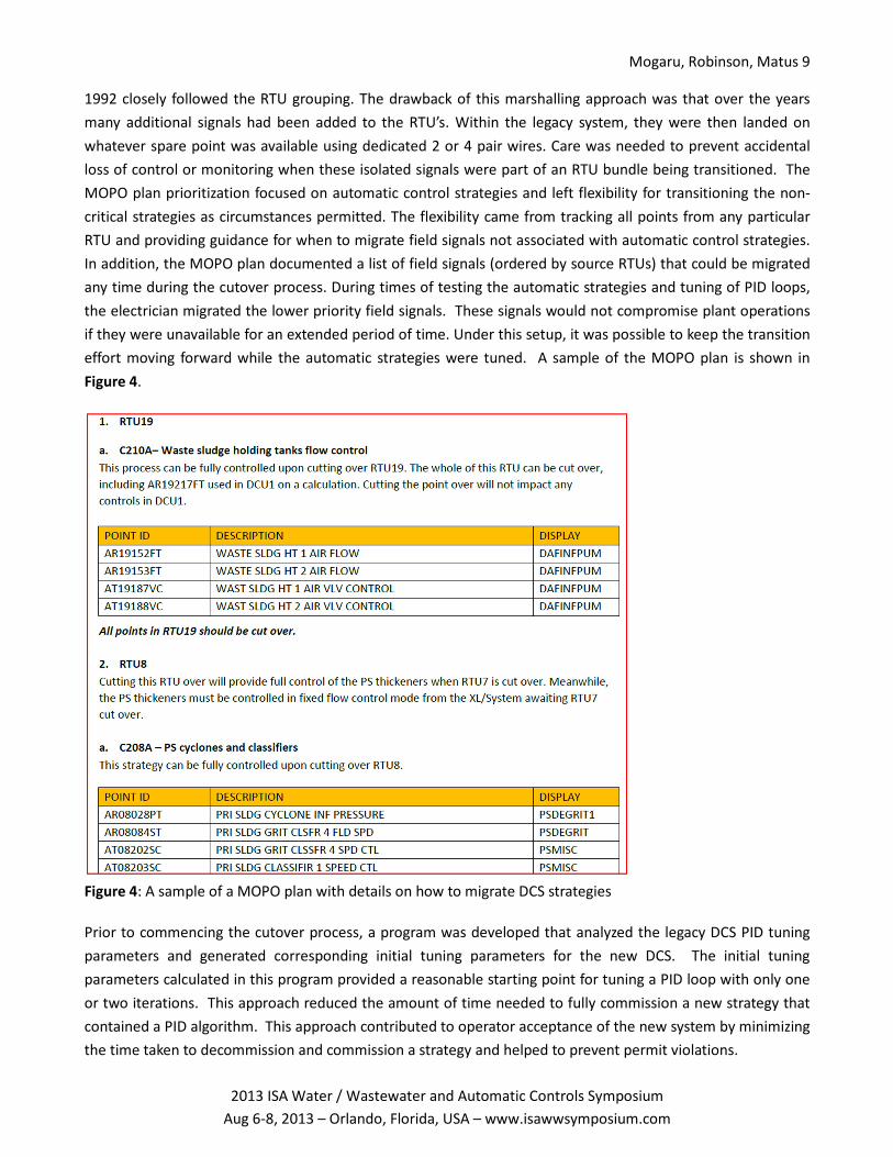
In addition, the MOPO plan documented a list of field signals (ordered by source RTUs) that could be migrated
any time during the cutover process. During times of testing the automatic strategies and tuning of PID loops,
the electrician migrated the lower priority field signals. These signals would not compromise plant operations
if they were unavailable for an extended period of time. Under this setup, it was possible to keep the transition
effort moving forward while the automatic strategies were tuned. A sample of the MOPO plan is shown in
Figure 4.
Figure 4: A sample of a MOPO plan with details on how to migrate DCS strategies
Prior to commencing the cutover process, a program was developed that analyzed the legacy DCS PID tuning
parameters and generated corresponding initial tuning parameters for the new DCS. The initial tuning
parameters calculated in this program provided a reasonable starting point for tuning a PID loop with only one
or two iterations. This approach reduced the amount of time needed to fully commission a new strategy that
contained a PID algorithm. This approach contributed to operator acceptance of the new system by minimizing
the time taken to decommission and commission a strategy and helped to prevent permit violations.

Mogaru, Robinson, Matus 10
2013 ISA Water / Wastewater and Automatic Controls Symposium
Aug 6-8, 2013 – Orlando, Florida, USA – www.isawwsymposium.com
The first day of the cutover process, the project team did a dry run of migrating a strategy from the legacy DCS
to the new DCS and back to the legacy DCS. This exercise was important to determine what it will take to
revert a strategy to the legacy system in the event that unexpected problems were encountered. During the
transition process there was an end of day meeting for discussion of strategies to be commissioned the
following day. Concerns and precautionary measures were noted. A brief meeting was held the following day
in the morning just before moving wires to confirm the planned activity with plant operations and get a “go/no
go” decision for the day’s cutover activity. This level of communication was essential to maintaining operator
acceptance of the daily cutover process.
The MOPO plan was followed during the cutover process with full tuning of a strategy being completed and
approved by operations before initiating cutover of another strategy. The approach identified and dealt with
transition issues as they arose and contributed to maintaining stable process control. Stable process control
helped to prevent release of untreated wastewater and kept the plant in compliance with local, state, and
federal regulations. It was known that as cutover process progressed, some strategies would be on the legacy
system and some would be on the new DCS. In order to guide operators as to which system was in control, a
visual method was developed to communicate which strategies had been migrated in addition to the recording
the information in the shift log book. A migration data point was declared in the legacy system for each
strategy and associated with a banner on each legacy graphic. This banner is animated by toggling the strategy
data point from false to true after the strategy is migrated. Figure 5 shows a graphic in the legacy system that
provided the means to set the migration data points. Figure 6 shows a graphic for a process area that had been
migrated to the new DCS. The banner tells the operator to look to the new system. Figure 7 shows an overview
graphic where only one process has been migrated to the new DCS. Therefore, the banner covers only that
portion that had been migrated. By routing operations to the correct DCS using a graphics banner approach,
minimal time was wasted when an operator needed to make an adjustment and helped contribute to
acceptance of the new system.
Figure 5: Interface to set bits to dynamically route operations to the new DCS
These strategies have been cutover. Data point set to value of 1

Mogaru, Robinson, Matus 11
2013 ISA Water / Wastewater and Automatic Controls Symposium
Aug 6-8, 2013 – Orlando, Florida, USA – www.isawwsymposium.com
Figure 6: Process graphic with banner routing operations to new DCS
Figure 7: Overview graphic with banner routing operations to new DCS for only one process in the overview
Comprehensive Documentation
Over the life of the legacy DCS there have been several process upgrades which needed thorough vetting of the
existing control descriptions to properly incorporate any changes in the system into the updated control
descriptions. A major effort went into confirming operation of the existing reports on the new system. The
Operator and Maintenance (O&M) manuals for the new DCS were completed after commissioning but were
based on a thorough review of the legacy O&M to confirm they matched the current control strategies.
Operator and Maintenance (O&M) Manuals
Documentation is the solid bridge between the legacy DCS and the new DCS. A lot of effort was put to clearly
document the many pieces of the application. These included, but were not limited to, graphic macros,
control macros, application development standards and conventions, control descriptions, reports and more.

Mogaru, Robinson, Matus 12
2013 ISA Water / Wastewater and Automatic Controls Symposium
Aug 6-8, 2013 – Orlando, Florida, USA – www.isawwsymposium.com
The emphasis put on the documentation was geared towards providing a firm guidance on future system
expansion while at the same time providing information about the system.
The O&M was broken down into several sections to provide an easy way of accessing system information. For
example, documentation related to standards and conventions was a standalone section with several
subsections. In order to provide easy access to the O&M, the process control sheets have hyperlinks on them
from which maintenance or the system administrator can easily call the document related to any particular
control strategy. This form of online documentation is easy to update whenever a control strategy is modified
as opposed to performing a physical change out of pages on hard copy manuals.
Lessons Learned and Recovery Effort
The MOPO plan provided crucial guidance during the cutover process. However, due to an oversight in not
considering equipment accumulated runtimes while developing the MOPO plan, migrating the accumulated
runtimes from the legacy system and reconciling it into the new DCS was not done during the cutover.
Contingency measures were put in place after commissioning to backfill the accumulated runtimes and
reconcile them into the new DCS. Also, while comprehensive in-house testing and final witnessed testing
minimized time spent in commissioning the strategies, primary effluent (PE) control strategy complexities led
to unexpected problems after cutover. Some of the problems involved strategy bumpless transfer from
manual flow control to automatic flow control and PID loop tuning. The one day dry run to migrate a strategy
to the new DCS and move it back to the legacy DCS proved to be a vital knowledge asset because we quickly
followed the same steps to move the PE strategies back to the legacy DCS for further analysis and studying.
After figuring out the solution, the strategies were migrated the following day successfully.
Summary
At the onset of the Village Creek DCS Implementation project, a comprehensive MOPO plan was determined to
be an integral part of the project execution. The project team put a lot of effort to continuously refine and
update the MOPO plan over the course of project execution. The final MOPO plan provided crucial guidance
before, during and after commissioning the new DCS. By following the MOPO plan during the cutover process,
we were able to minimize plant interruptions which in turn allowed the plant to avoid any permit violations.
Working with the plant to maintain compliance to all local, state and federal regulation was one of the major
deliverables. If in the future the plant experiences an unexpected catastrophic failure of plant operations
infrastructure, the MOPO plan will remain a critical component to be used to determine the order with which
to bring the system online.
After the final selection of the replacement DCS, a decision was made to utilize the additional capabilities of
the new DCS while at the same time maintaining the same look and feel of the legacy DCS. This decision was
meant to achieve the most operator acceptance of the new DCS which in turn will improve the plant’s ability
to maintain exceptional effluent treatment standards. In order to achieve this goal, the legacy DCS standards
were migrated; these included, but were not limited to, point tagging, graphic layout, color sequence and
animation schemes, graphics navigation standards, etc. While the legacy DCS utilized sub displays to provide
operators with an interface to enter process control set points, the capability of the new DCS was utilized
which allowed control pop ups instead of the sub displays. With control pop ups, operators can view all set

Mogaru, Robinson, Matus 13
2013 ISA Water / Wastewater and Automatic Controls Symposium
Aug 6-8, 2013 – Orlando, Florida, USA – www.isawwsymposium.com
points on one graphic as opposed to the sub displays where they had to scroll through several windows in
cases where multiple process set points were used.
In order to provide a stable process control, all strategies were thoroughly tested in house using detailed
testing procedures. The owner was also given an opportunity to witness process control testing. This rigorous
controls testing was facilitated by the capability of the new DCS to run the control strategies in virtual
controllers that act and function like actual controllers. Due to the successes of the witnessed functional
demonstration test, the effort of migrating the control strategies to the new DCS was reduced to loop tuning
which in turn provided the most plant up time.
Finally, the effort to develop and maintain detailed O&M manuals yielded immeasurable benefits during
commissioning and has remained a vital troubleshooting tool for the maintenance personnel. The goal from
the project onset was to maintain an O&M that is representative of the system and the programmed control
strategies.
List of Acronyms:
DCS .................. Distributed Control System
MOPO .............. Maintenance of Plant Operations
DCU.................. Distributed Control Unit
PE ..................... Primary Effluent
RTU .................. Remote Terminal Unit
TF ..................... Termination Facility
O&M ................ Operator and Maintenance
Main Author Name: Nathan Mogaru - [email protected]
Mr. Mogaru graduated from the University of Texas at Arlington with a B.S. Degree in Electrical Engineering.
He is an automation engineer at CDM Smith specializing in applications software development. Mr. Mogaru
has six years experience in project planning, control logic development for Programmable Logic Controllers
(PLCs) and Distributed Control Systems (DCSs), HMI graphic development, field commissioning and startups,
project documentation, and operator training.
Second Author Name: John Robinson
Mr. Robinson has 30 years of experience developing and implementing instrumentation and control systems,
24 of which he has specialized in water and wastewater treatment. Mr. Robinson's experience includes project
management, instrumentation specification, control logic development for programmable controller systems
(PLC) and distributed control systems (DCS), application programming, field startup, troubleshooting, operator
training, and pilot plant operation.
Third Author Name: Luke Matus
Mr. Matus has worked for the City of Fort Worth since May of 1988. His degree and background in
Instrumentation has provided an avenue to be involved in the development and implementation of process
control systems throughout the City of Fort Worth for both the Water and Wastewater Industries. He’s worked
on and maintained both PLC based architectures as well as DCS systems.