Seagrass Protection and Advanced Moorings
36
1 Modeling Advanced Mooring Systems in Cornish Harbours Seagrass Protection and Advanced Moorings Modeling of Advanced Mooring Systems in Cornish Harbours Spring 2021
Transcript of Seagrass Protection and Advanced Moorings

1
Modeling Advanced Mooring Systems in Cornish Harbours
Seagrass Protection and Advanced MooringsModeling of Advanced Mooring Systems in Cornish Harbours
Spring 2021

2
Modeling Advanced Mooring Systems in Cornish HarboursAdvanced mooring systems report
Tevi (Cornish for ‘grow’) is an EU-funded programme which aims to create both economic and environmental growth in Cornwall and the Isles of Scilly.
The initiative, which runs until 2022, provides small and medium-sized enterprises across the county with expert consultation, opportunities for recognition and certification, and grant funding. Our objective is to help enterprises make the most of the prized asset upon which they rely – our beautiful natural environment – by helping them grow their business.
We support enterprises to play a proactive role in growing and protecting the region’s unique natural environment, while also becoming more efficient with their natural resource use and minimising their waste in smart and innovative ways, as part of the global transition towards a circular economy.
Tevi’s Challenge Networks bring organisations together to collectively identify, and bring to market, solutions to environmental challenges that no one organisation can solve alone. Over the course of the three year programme Tevi will run a number of Challenge Networks, of which protecting seagrass through accelerating advanced moorings uptake, is one.
Tevi is led by the University of Exeter, and is delivered in partnership with the Cornwall Wildlife Trust, Cornwall Council and the Cornwall Development Company. Find out more about the programme at www.tevi.co.uk.

3
Modeling Advanced Mooring Systems in Cornish Harbours
1. Executive summary 4
2. Acknowledgements 4
3. Introduction 5
4. Input Data 6
4.1 Stakeholder survey 6
5. Vessels 7
5.1 Vessel sizes at Cornish harbours 7
5.2 Hydrodynamic modelling 8
6. Mooring 10
6.1 Existing moorings 10
6.2 Advanced Mooring Systems (AMS) 12
7. Environmental Data 15
7.1 Environmental baseline data 15
7.2 Environmental modelling parameters 16
8.Simulation 17
8.1 Baseline 18
8.2 Seaflex 19
8.3. Stirling 20
9. Results 21
9.1. Water Depth = 3m 21
9.2. Water Depth = 5m 25
9.3. Comparison to Baseline 29
10. Findings 30
11. Recommendations 31
12. References 32
13. Abbreviations 32
1. Appendix A – Beaufort Scale 33
2. Appendix B – Reference vessel details 33
3. Appendix C – Vessel RAO 34
Table of contents

Modeling Advanced Mooring Systems in Cornish Harbours
4Photo 1. Scilly seagrass beds. Photograph taken by Matt Slater of Cornwall Wildlife Trust.
1. Executive summaryThis report details the output of a desktop study into the performance of Advanced Mooring Systems (AMS). The objective of the AMS is to reduce the impact of leisure moorings on fragile estuarine and riverbed ecosystems, specifically on Eelgrass beds, a focus of the AMS Tevi project. This work compares a collection of 3 market ready AMS in the context of ‘typical’ Cornish harbour environments. The report also assesses the relative performance against the incumbent, traditional block and chain swing mooring. The work is split into two phases. The first phase involved the collation of input baseline data from local harbour authorities and marinas this included Falmouth Harbour Commissioners, Fowey Harbour Commissioners, Mylor Yacht Harbour and St. Mawes Harbour. The second phase involved the numerical modelling of AMS using OrcaFlex marine dynamics software. The modelling considered two types of AMS: Seaflex and Stirling, with two vessel types: a 33ft Motor Launch and a 40ft Sailing Yacht, both of which have been characterised hydrodynamically and hydrostatically for the purpose of this study.
The AMS were set-up for conditions which represent the data gathered in phase 1. Including depths, tidal range, wave height, tidal current and windspeed expected over a summer season.
The analysis showed that the vessel response when connected to AMS was very similar to that of the block and chain, and that the Seaflex system provided similar and sometimes reduced mooring loads. The Stirling system was found to be the most effective AMS in shallow water, in scenarios where the other AMS would not be suited. It does however, in the configuration demonstrated suffer large mooring loads/tensions. The reader should note that this analysis is yet un-validated. Scaled physical model testing and/or ideally a full-scale sea trial would bring further confidence to the modelling and cement conclusions.
This work would not have been possible without the interaction and contributions of several key individuals and organisations –
• Vicki Spooner of Falmouth Harbour Commission
• Claire Hoddinott of Fowey Harbour Commission
• Cullum Matheson of Mylor Yacht Harbour
• Martin Bidmead of St Mawes Harbour
• Emma Walker at Cornwall Council for Truro Harbour
Also input from Hazelett Marine, Seaflex and Mark Parry of Ocean Conservation trust (Sterling mooring).
2. Acknowledgements

Modeling Advanced Mooring Systems in Cornish Harbours
5
Seagrass meadows provide a diverse range of ecosystem services. This includes habitat for threatened marine species, nursery environments for commercially significant fish stock, reduction of coastal erosion, and carbon sequestration. However, they are one of the UK’s most threatened habitats.
Work Tevi has delivered on seagrass protection identified one threat to seagrass is associated with mooring type. Results showed that the mass deployment of traditional (block and chain) swing mooring systems for recreational craft in shallow water contributes to the decline of these vital habitats. This is due to the scouring of the seabed when in contact with ground chain. The impact of this could be hugely reduced by employing the use of Advanced Mooring Systems (AMS) which minimise components contacting the seabed [1].
The main objective of the work is to model the behaviour of AMS for mid-size recreational craft in typical Cornish harbours, allowing assessment of vessel motions and loads. The aim of this work is to provide harbours with more information regarding a environmental alternative to the traditional block and chain moorings.
This report summarises modelling undertaken by Morek Engineering Ltd to compare the performance of three types of AMS against a traditional block and chain mooring. OrcaFlex marine dynamics software has been used to simulate the response of typical recreational vessels moored with three configurations of AMS. These simulations account for the environmental conditions expected at Cornish harbours.
3. Introduction
Photo 2. Seagrass reflections. Photograph taken by Matt Slater of Cornwall Wildlife Trust.
Modeling Advanced Mooring Systems in Cornish Harbours
6Photo 3. Scilly seagrass beds. Photograph taken by Matt Slater of Cornwall Wildlife Trust.
4.1. Stakeholder survey
To fully characterise the expected use of AMS it was important to receive input and guidance from a range of Cornish harbour authorities and marinas. Morek designed a baseline survey to:
• determine the status of existing small boat moorings;
• gain relevant input environmental conditions; and
• to gauge interest in deployment of AMS.
All the five authorities and marinas that were contacted provided valuable input into the study. It should be noted that although they were keen to support the programme Truro Harbour Authority were not able to present a detailed response as they do not have any existing moorings within their harbour. General survey feedback is shown below, and more detailed feedback on environmental conditions, vessel sizes and mooring types follows throughout the report in Sections 5.1, 6.1 and 7.1.
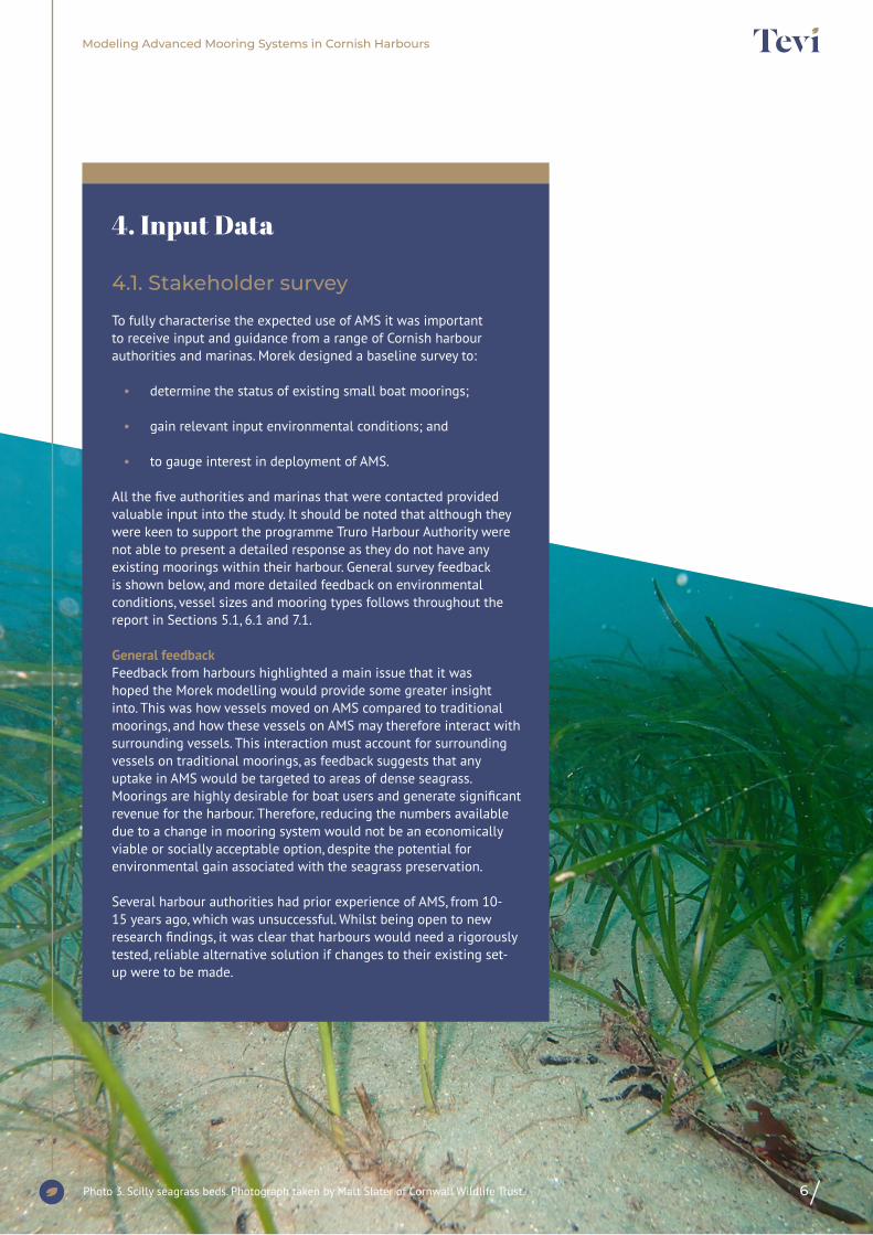
General feedbackFeedback from harbours highlighted a main issue that it was hoped the Morek modelling would provide some greater insight into. This was how vessels moved on AMS compared to traditional moorings, and how these vessels on AMS may therefore interact with surrounding vessels. This interaction must account for surrounding vessels on traditional moorings, as feedback suggests that any uptake in AMS would be targeted to areas of dense seagrass. Moorings are highly desirable for boat users and generate significant revenue for the harbour. Therefore, reducing the numbers available due to a change in mooring system would not be an economically viable or socially acceptable option, despite the potential for environmental gain associated with the seagrass preservation.
Several harbour authorities had prior experience of AMS, from 10-15 years ago, which was unsuccessful. Whilst being open to new research findings, it was clear that harbours would need a rigorously tested, reliable alternative solution if changes to their existing set-up were to be made.
4. Input Data

7
Modeling Advanced Mooring Systems in Cornish Harbours
5. Vessels
5.1. Vessel sizes at Cornish harbours
Figure 1 shows the relative ratios of vessel length at the four harbours. Falmouth, as expected with access to deeper waters, has the largest proportion of over 10m vessels, followed by Mylor. Fowey has the most significant proportion of smaller vessels, again reflected by the lower depth (and drying) moorings.
It was necessary to identify and define suitable example vessels for the project. Examples have been selected to cover the broadest spectrum of Cornish recreational boating likely to occupy berths suited to AMS. These two vessel types are:
• Motor craft, with shallow draft whose mooring loads are driven predominantly by wind drag on the topside.
• Sailing vessels, with deep keels whose mooring loads are driven predominantly by current drag and wave drift.
For this study, the largest class of these of these types of vessel that would be suited for swing moorings have been selected, to represent the worst case in mooring loads. To enable this, example vessels types from the naval architecture software DelftShip have been adopted. This provides the study with representative geometry, mass properties and hydrodynamic drag coefficients for use in the study. The basis vessels are defined below in Figure 2. For detailed input data see Table 8 in Appendix 2.
• Motor Launch - 10.2m (33ft) cabin cruiser, with a draft of 0.8m and displacement of 10te.
• Sailing Vessel - 12m (40ft) yacht, with a draft of 2m and displacement of 6t.
Figure 1: Percentage of vessel sizes Figure 2: Images of selected vessels
8
Modeling Advanced Mooring Systems in Cornish Harbours
5.2. Hydrodynamic modelling
To assess the influence of the vessels on the AMS, hydrodynamic representations were generated which were used in the time domain analysis. The vessel response was characterised in two ways:
• Diffraction analysis to define the vessel response to 1st and 2nd order wave loading.
• Morrison’s drag coefficients to define the vessel response to current and wind drag.
The diffraction analysis was performed in Orcina’s OrcaWave software, which interfaces directly with OrcaFlex, reducing the uncertainty typical of importing this type of data into OrcaFlex.
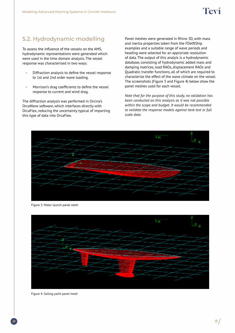
Panel meshes were generated in Rhino 3D, with mass and inertia properties taken from the FDelftShip examples and a suitable range of wave periods and heading were selected for an approriate resolution of data. The output of this analyis is a hydrodynamic database, consisting of hydrodynamic added mass and damping matrices, load RAOs, displacement RAOs and Quadratic transfer functions, all of which are required to characterize the effect of the wave climate on the vessel. The screenshots (Figure 3 and Figure 4) below show the panel meshes used for each vessel.
Note that for the purpose of this study, no validation has been conducted on this analysis as it was not possible within the scope and budget. It would be recommended to vaildate the response models against tank test or full scale data.
Figure 3: Motor launch panel mesh
Figure 4: Sailing yacht panel mesh
9
Modeling Advanced Mooring Systems in Cornish Harbours
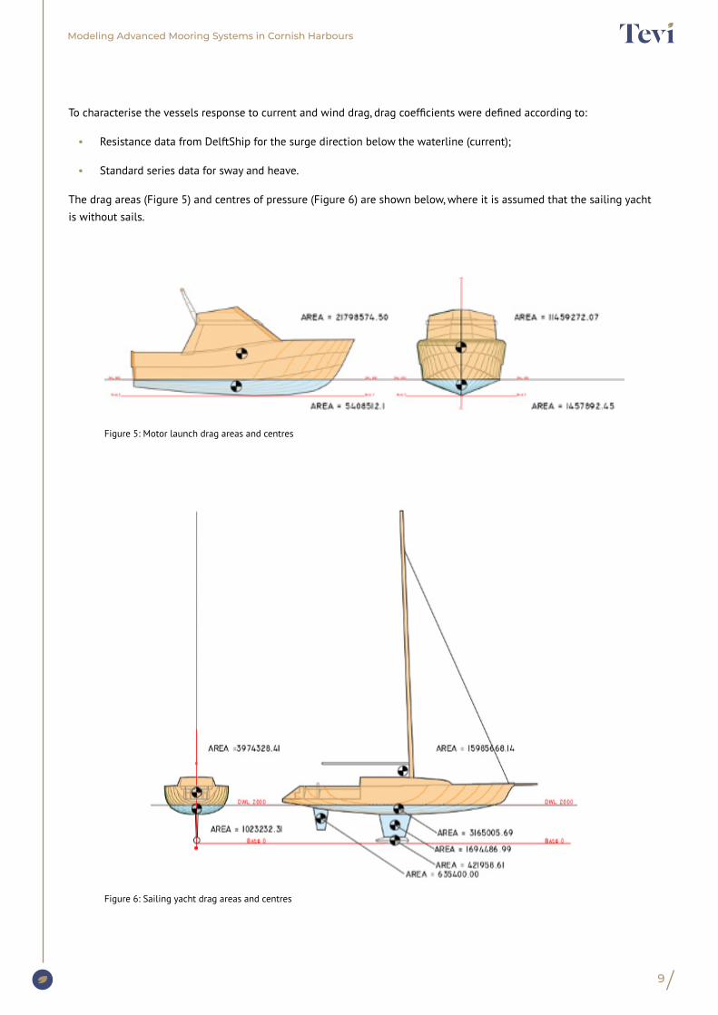
To characterise the vessels response to current and wind drag, drag coefficients were defined according to:
• Resistance data from DelftShip for the surge direction below the waterline (current);
• Standard series data for sway and heave.
The drag areas (Figure 5) and centres of pressure (Figure 6) are shown below, where it is assumed that the sailing yacht is without sails.
Figure 5: Motor launch drag areas and centres
Figure 6: Sailing yacht drag areas and centres
10
Modeling Advanced Mooring Systems in Cornish Harbours
6. Mooring
6.1. Existing moorings
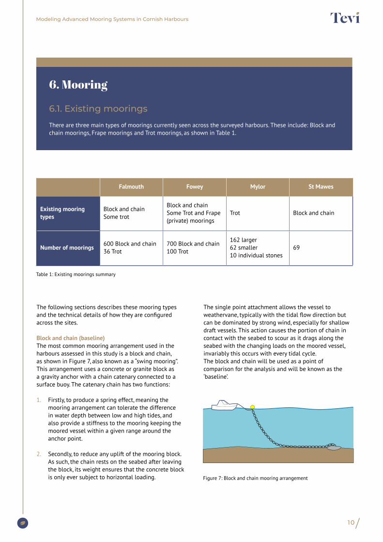
There are three main types of moorings currently seen across the surveyed harbours. These include: Block and chain moorings, Frape moorings and Trot moorings, as shown in Table 1.
The following sections describes these mooring types and the technical details of how they are configured across the sites.
Block and chain (baseline)The most common mooring arrangement used in the harbours assessed in this study is a block and chain, as shown in Figure 7, also known as a “swing mooring”. This arrangement uses a concrete or granite block as a gravity anchor with a chain catenary connected to a surface buoy. The catenary chain has two functions:
1. Firstly, to produce a spring effect, meaning the mooring arrangement can tolerate the difference in water depth between low and high tides, and also provide a stiffness to the mooring keeping the moored vessel within a given range around the anchor point.
2. Secondly, to reduce any uplift of the mooring block. As such, the chain rests on the seabed after leaving the block, its weight ensures that the concrete block is only ever subject to horizontal loading.
The single point attachment allows the vessel to weathervane, typically with the tidal flow direction but can be dominated by strong wind, especially for shallow draft vessels. This action causes the portion of chain in contact with the seabed to scour as it drags along the seabed with the changing loads on the moored vessel, invariably this occurs with every tidal cycle.The block and chain will be used as a point of comparison for the analysis and will be known as the ‘baseline’.
Figure 7: Block and chain mooring arrangement
Falmouth Fowey Mylor St Mawes
Existing mooring types
Block and chainSome trot
Block and chainSome Trot and Frape (private) moorings
Trot Block and chain
Number of moorings 600 Block and chain36 Trot
700 Block and chain100 Trot
162 larger 62 smaller10 individual stones
69
Table 1: Existing moorings summary

Modeling Advanced Mooring Systems in Cornish Harbours
11
In Fowey, as an example, a typical block and chain will be constructed as follows:
Anchor ¾ tonne granite weight
Ground Chain 4m x 44mm long link chain
Riser 7m x ½ inch short link galvanised chain
Surface buoy Hippo type hard buoy with shackle
Rode to Vessel Vessel owner supplied
Trot mooringA trot mooring differs from a swing mooring in that instead of using a heavy ground anchor a heavy ground chain is laid between two granite blocks, this allows two types of mooring.
• At Fowey two chain risers per vessel provide fore and aft connection points, this ensures moored vessels maintain station and heading throughout the tide and are typically used for larger vessels and preferred in constrained waterways with current.
• At Mylor the trot is used to anchor rows of individual swing moorings. The heavy ground chain is connected periodically with 32mm spurs for each individual swing mooring with a swivel and 19mm riser to a surface pickup buoy.
Other than the swing type aspect of the Trot mooring the interaction with the seabed is limited, there is much less scope for the heavy ground chain to move if laid straight and with large gravity anchors on either side. The Trot has not been specifically considered in this study, but the swing mooring aspect as demonstrated at Mylor is captured.
Frape mooringFrape moorings are used to connect smaller vessels to shore based anchors and as such are in shallow water and tend to dry out. They are more suited to tenders and small motor craft. They also typically have little or no interaction with the seabed other than the direct axial running of the line when the vessel is pulled to shore or sent back to moor. As a result, they have not been considered in this study.
Photo 4. Stalked jellyfish. Photograph taken by Fiona Crouch, Natural England
12
Modeling Advanced Mooring Systems in Cornish Harbours
6.2. Advanced Mooring Systems (AMS)
This section outlines the AMS considered in the scope of this study. The AMS systems were prescribed by Tevi, following feedback and input from the participants of this Challenge Network, and the technical details of the mooring components were provided by the suppliers.
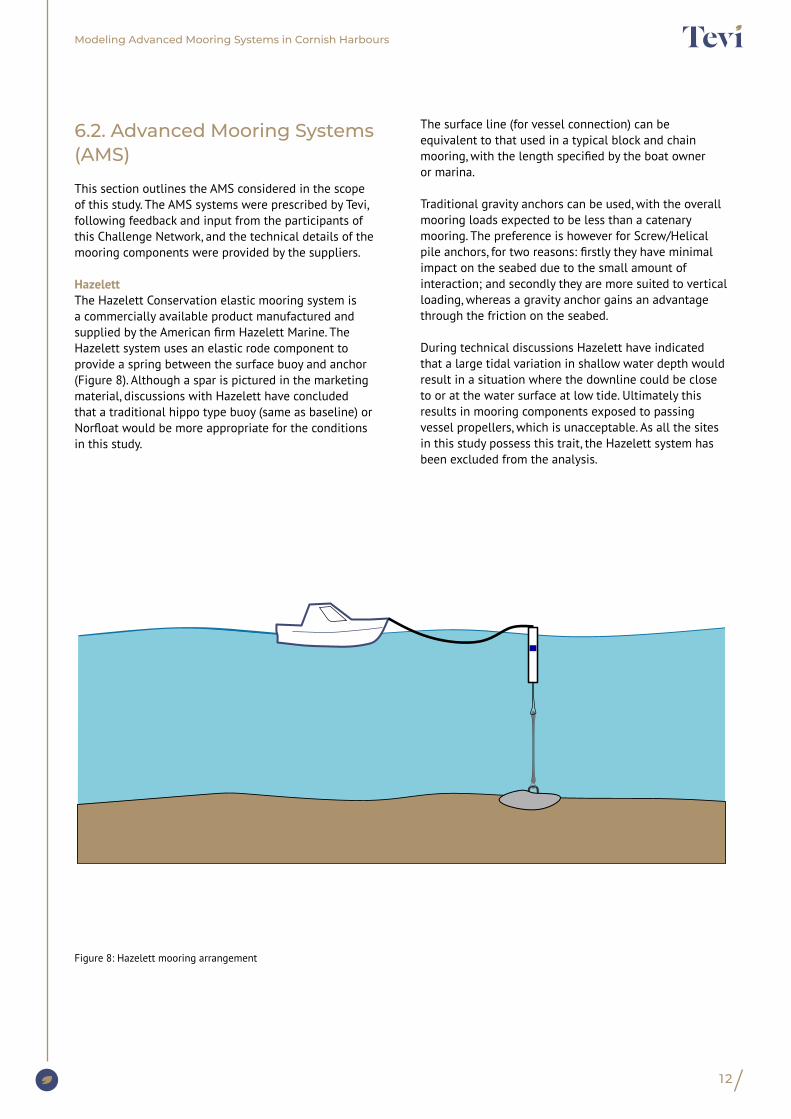
Hazelett The Hazelett Conservation elastic mooring system is a commercially available product manufactured and supplied by the American firm Hazelett Marine. The Hazelett system uses an elastic rode component to provide a spring between the surface buoy and anchor (Figure 8). Although a spar is pictured in the marketing material, discussions with Hazelett have concluded that a traditional hippo type buoy (same as baseline) or Norfloat would be more appropriate for the conditions in this study.
The surface line (for vessel connection) can be equivalent to that used in a typical block and chain mooring, with the length specified by the boat owner or marina.
Traditional gravity anchors can be used, with the overall mooring loads expected to be less than a catenary mooring. The preference is however for Screw/Helical pile anchors, for two reasons: firstly they have minimal impact on the seabed due to the small amount of interaction; and secondly they are more suited to vertical loading, whereas a gravity anchor gains an advantage through the friction on the seabed.
During technical discussions Hazelett have indicated that a large tidal variation in shallow water depth would result in a situation where the downline could be close to or at the water surface at low tide. Ultimately this results in mooring components exposed to passing vessel propellers, which is unacceptable. As all the sites in this study possess this trait, the Hazelett system has been excluded from the analysis.
Figure 8: Hazelett mooring arrangement
13
Modeling Advanced Mooring Systems in Cornish Harbours
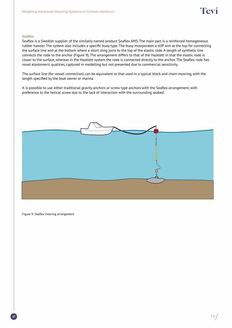
SeaflexSeaflex is a Swedish supplier of the similarly named product Seaflex AMS. The main part is a reinforced homogeneous rubber hawser. The system also includes a specific buoy type. The buoy incorporates a stiff arm at the top for connecting the surface line and at the bottom where a short sling joins to the top of the elastic rode. A length of synthetic line connects the rode to the anchor (Figure 9). The arrangement differs to that of the Hazelett in that the elastic rode is closer to the surface, whereas in the Hazelett system the rode is connected directly to the anchor. The Seaflex rode has novel elastomeric qualities, captured in modelling but not presented due to commercial sensitivity.
The surface line (for vessel connection) can be equivalent to that used in a typical block and chain mooring, with the length specified by the boat owner or marina.
It is possible to use either traditional gravity anchors or screw type anchors with the Seaflex arrangement, with preference to the helical screw due to the lack of interaction with the surrounding seabed.
Figure 9: Seaflex mooring arrangement
14
Modeling Advanced Mooring Systems in Cornish Harbours
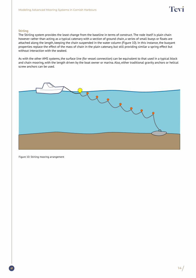
StirlingThe Stirling system provides the least change from the baseline in terms of construct. The rode itself is plain chain however rather than acting as a typical catenary with a section of ground chain, a series of small buoys or floats are attached along the length, keeping the chain suspended in the water column (Figure 10). In this instance, the buoyant properties replace the effect of the mass of chain in the plain catenary, but still providing similar a spring effect but without interaction with the seabed.
As with the other AMS systems, the surface line (for vessel connection) can be equivalent to that used in a typical block and chain mooring, with the length driven by the boat owner or marina. Also, either traditional gravity anchors or helical screw anchors can be used.
Figure 10: Stirling mooring arrangement
15
Modeling Advanced Mooring Systems in Cornish Harbours
7. Environmental Data
7.1. Environmental baseline data
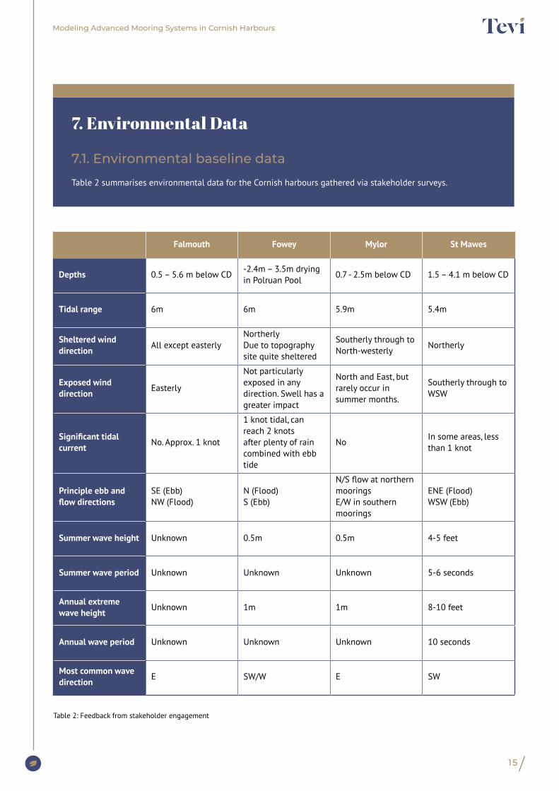
Table 2 summarises environmental data for the Cornish harbours gathered via stakeholder surveys.
Falmouth Fowey Mylor St Mawes
Depths 0.5 – 5.6 m below CD-2.4m – 3.5m drying in Polruan Pool
0.7 - 2.5m below CD 1.5 – 4.1 m below CD
Tidal range 6m 6m 5.9m 5.4m
Sheltered wind direction All except easterly
NortherlyDue to topography site quite sheltered
Southerly through to North-westerly
Northerly
Exposed wind direction Easterly
Not particularly exposed in any direction. Swell has a greater impact
North and East, but rarely occur in summer months.
Southerly through to WSW
Significant tidal current No. Approx. 1 knot
1 knot tidal, can reach 2 knots after plenty of rain combined with ebb tide
NoIn some areas, less than 1 knot
Principle ebb and flow directions
SE (Ebb)NW (Flood)
N (Flood)S (Ebb)
N/S flow at northern moorings E/W in southern moorings
ENE (Flood)WSW (Ebb)
Summer wave height Unknown 0.5m 0.5m 4-5 feet
Summer wave period Unknown Unknown Unknown 5-6 seconds
Annual extreme wave height Unknown 1m 1m 8-10 feet
Annual wave period Unknown Unknown Unknown 10 seconds
Most common wave direction E SW/W E SW
Table 2: Feedback from stakeholder engagement
Modeling Advanced Mooring Systems in Cornish Harbours
16
7.2. Environmental modelling parameters
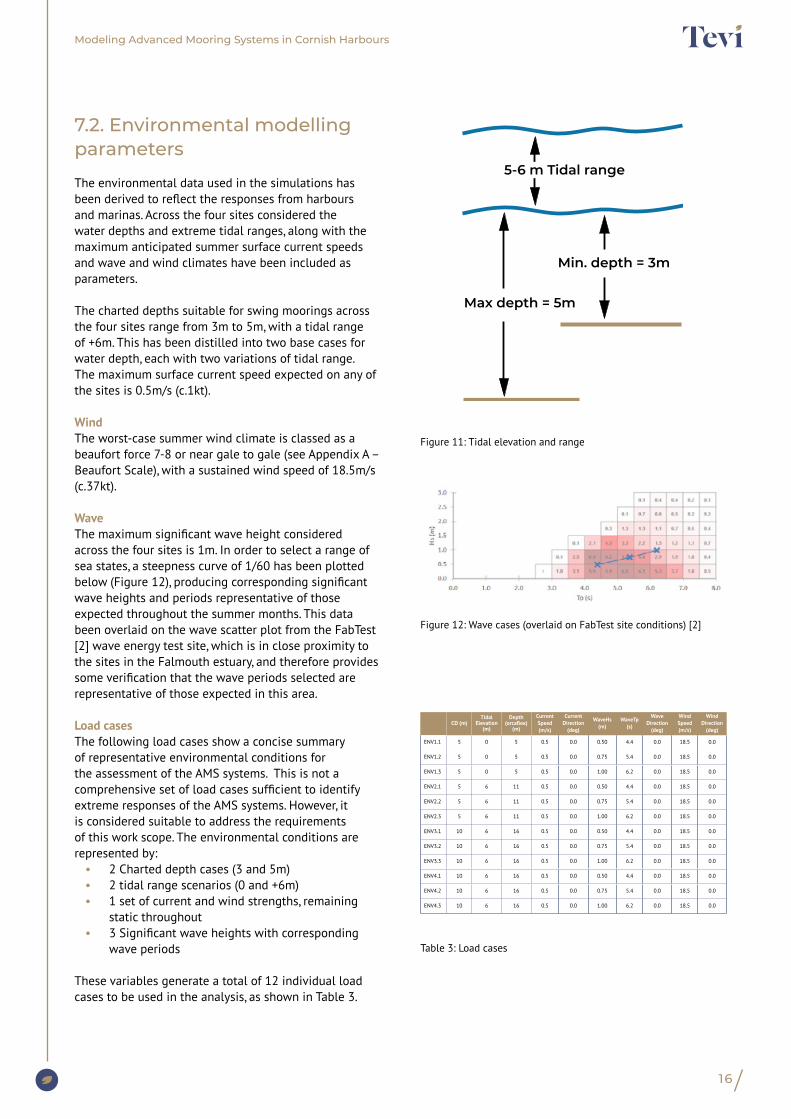
The environmental data used in the simulations has been derived to reflect the responses from harbours and marinas. Across the four sites considered the water depths and extreme tidal ranges, along with the maximum anticipated summer surface current speeds and wave and wind climates have been included as parameters.
The charted depths suitable for swing moorings across the four sites range from 3m to 5m, with a tidal range of +6m. This has been distilled into two base cases for water depth, each with two variations of tidal range. The maximum surface current speed expected on any of the sites is 0.5m/s (c.1kt).
WindThe worst-case summer wind climate is classed as a beaufort force 7-8 or near gale to gale (see Appendix A – Beaufort Scale), with a sustained wind speed of 18.5m/s (c.37kt).
WaveThe maximum significant wave height considered across the four sites is 1m. In order to select a range of sea states, a steepness curve of 1/60 has been plotted below (Figure 12), producing corresponding significant wave heights and periods representative of those expected throughout the summer months. This data been overlaid on the wave scatter plot from the FabTest [2] wave energy test site, which is in close proximity to the sites in the Falmouth estuary, and therefore provides some verification that the wave periods selected are representative of those expected in this area.
Load casesThe following load cases show a concise summary of representative environmental conditions for the assessment of the AMS systems. This is not a comprehensive set of load cases sufficient to identify extreme responses of the AMS systems. However, it is considered suitable to address the requirements of this work scope. The environmental conditions are represented by:
• 2 Charted depth cases (3 and 5m)• 2 tidal range scenarios (0 and +6m)• 1 set of current and wind strengths, remaining
static throughout• 3 Significant wave heights with corresponding
wave periods
These variables generate a total of 12 individual load cases to be used in the analysis, as shown in Table 3.
Max depth = 5m
Min. depth = 3m
5-6 m Tidal range
Figure 12: Wave cases (overlaid on FabTest site conditions) [2]
Table 3: Load cases
Figure 11: Tidal elevation and range
CD (m)Tidal
Elevation (m)
Depth (orcaflex)
(m)
Current Speed (m/s)
Current Direction
(deg)
WaveHs (m)
WaveTp (s)
Wave Direction
(deg)
Wind Speed(m/s)
Wind Direction
(deg)
ENV1.1 5 0 5 0.5 0.0 0.50 4.4 0.0 18.5 0.0
ENV1.2 5 0 5 0.5 0.0 0.75 5.4 0.0 18.5 0.0
ENV1.3 5 0 5 0.5 0.0 1.00 6.2 0.0 18.5 0.0
ENV2.1 5 6 11 0.5 0.0 0.50 4.4 0.0 18.5 0.0
ENV2.2 5 6 11 0.5 0.0 0.75 5.4 0.0 18.5 0.0
ENV2.3 5 6 11 0.5 0.0 1.00 6.2 0.0 18.5 0.0
ENV3.1 10 6 16 0.5 0.0 0.50 4.4 0.0 18.5 0.0
ENV3.2 10 6 16 0.5 0.0 0.75 5.4 0.0 18.5 0.0
ENV3.3 10 6 16 0.5 0.0 1.00 6.2 0.0 18.5 0.0
ENV4.1 10 6 16 0.5 0.0 0.50 4.4 0.0 18.5 0.0
ENV4.2 10 6 16 0.5 0.0 0.75 5.4 0.0 18.5 0.0
ENV4.3 10 6 16 0.5 0.0 1.00 6.2 0.0 18.5 0.0

Modeling Advanced Mooring Systems in Cornish Harbours
17
The numerical modelling has been undertaken with the marine dynamics software Orcaflex, the world’s leading package for the dynamic analysis of offshore marine systems, regularly used for the design and analysis of moorings.
Dynamic simulations were run in OrcaFlex software, for each of the load cases selected. Models were generated for each of the AMS arrangements in the OrcaFlex user interface, capturing the following attributes of the systems:
• Vessel response characteristics: from the diffraction analysis detailed above.
• Behaviour of the buoys: hydrostatics and hydrodynamics.
• Behaviour of the chain and synthetic lines: structural stiffness and hydrodynamics.
• The anchor is assumed as fixed, with the end of the line attached to a point on the seabed, the loads will be reported for consideration of anchoring technologies.
The dynamic simulations were run for 3600seconds (60 minutes). The following environmental conditions were applied:
• Tidal current and wind: applied as a constant static load on the vessel and mooring components.
• Wave conditions: Pierson Moskovitz wave spectra with peak shape parameter, γ = 1, the same seed has been used for each environmental case throughout, resulting in identical wave trains for each mooring arrangement.
8. Simulation
Photo 5. Scilly seagrass beds. Photograph taken by Matt Slater of Cornwall Wildlife Trust.
18
Modeling Advanced Mooring Systems in Cornish Harbours
8.1. Baseline
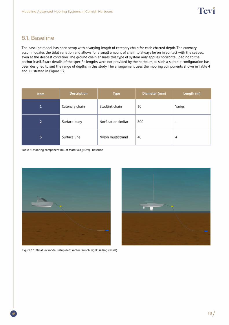
The baseline model has been setup with a varying length of catenary chain for each charted depth. The catenary accommodates the tidal variation and allows for a small amount of chain to always be on in contact with the seabed, even at the deepest condition. The ground chain ensures this type of system only applies horizontal loading to the anchor itself. Exact details of the specific lengths were not provided by the harbours, as such a suitable configuration has been designed to suit the range of depths in this study. The arrangement uses the mooring components shown in Table 4 and illustrated in Figure 13.
Figure 13: OrcaFlex model setup (left: motor launch, right: sailing vessel)
Table 4: Mooring component Bill of Materials (BOM) - baseline
Item Description Type Diameter (mm) Length (m)
1 Catenary chain Studlink chain 30 Varies
2 Surface buoy Norfloat or similar 800 -
3 Surface line Nylon multistrand 40 4

19
Video recording demonstrating vessel movement on Stirling and Seaflex systems alongside that of the baseline (block and chain mooring).
Modeling Advanced Mooring Systems in Cornish Harbours
8.1. Recording snapshot of OrcaFlex simulation
20
Modeling Advanced Mooring Systems in Cornish Harbours
8.2. Seaflex
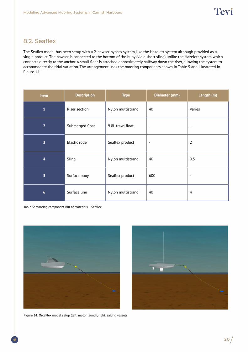
The Seaflex model has been setup with a 2-hawser bypass system, like the Hazelett system although provided as a single product. The hawser is connected to the bottom of the buoy (via a short sling) unlike the Hazelett system which connects directly to the anchor. A small float is attached approximately halfway down the riser, allowing the system to accommodate the tidal variation. The arrangement uses the mooring components shown in Table 5 and illustrated in Figure 14.
Figure 14: OrcaFlex model setup (left: motor launch, right: sailing vessel)
Table 5: Mooring component Bill of Materials – Seaflex
Item Description Type Diameter (mm) Length (m)
1 Riser section Nylon multistrand 40 Varies
2 Submerged float 9.8L trawl float - -
3 Elastic rode Seaflex product - 2
4 Sling Nylon multistrand 40 0.5
5 Surface buoy Seaflex product 600 -
6 Surface line Nylon multistrand 40 4
Modeling Advanced Mooring Systems in Cornish Harbours
21
8.3. Stirling
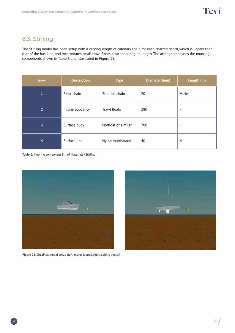
The Stirling model has been setup with a varying length of catenary chain for each charted depth, which is lighter than that of the baseline, and incorporates small trawl floats attached along its length. The arrangement uses the mooring components shown in Table 6 and illustrated in Figure 15.
Figure 15: OrcaFlex model setup (left: motor launch, right: sailing vessel)
Table 6: Mooring component Bill of Materials - Stirling
Item Description Type Diameter (mm) Length (m)
1 Riser chain Studlink chain 20 Varies
2 In line buoyancy Trawl floats 280 -
3 Surface buoy Norfloat or similar 700 -
4 Surface line Nylon multistrand 40 4
22
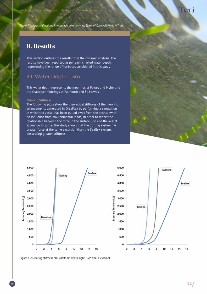
This section outlines the results from the dynamic analysis. The results have been reported as per each charted water depth, representing the range of harbours considered in this study.
9.1. Water Depth = 3m
This water depth represents the moorings at Fowey and Mylor and the shallower moorings at Falmouth and St. Mawes.
Mooring StiffnessThe following plots show the theoretical stiffness of the mooring arrangements generated in OrcaFlex by performing a simulation in which the vessel has been pulled away from the anchor (with no influence from environmental loads) in order to report the relationship between the force in the surface line and the vessel excursion in surge. The study shows that the Stirling system has greater force at the same excursion than the Seaflex system, possessing greater stiffness.
9. Results
Figure 16: Mooring stiffness plots (left: 3m depth, right: +6m tidal elevation)
Photo 7.Seagrass reflections. Photograph taken by Matt Slater of Cornwall Wildlife Trust.
Modeling Advanced Mooring Systems in Cornish Harbours
23
Modeling Advanced Mooring Systems in Cornish Harbours
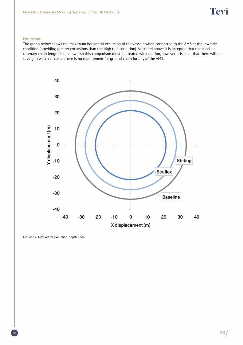
ExcursionsThe graph below shows the maximum horizontal excursion of the vessels when connected to the AMS at the low tide condition (providing greater excursions than the high tide condition). As stated above it is accepted that the baseline catenary chain length is unknown, so this comparison must be treated with caution, however it is clear that there will be saving in watch circle as there is no requirement for ground chain for any of the AMS.
Figure 17: Max vessel excursion, depth = 5m
24
Modeling Advanced Mooring Systems in Cornish Harbours
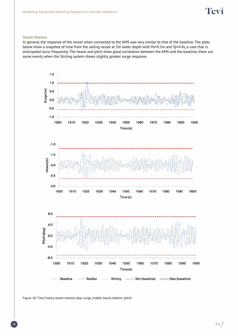
Vessel MotionsIn general, the response of the vessel when connected to the AMS was very similar to that of the baseline. The plots below show a snapshot of time from the sailing vessel at 3m water depth with Hs=0.5m and Tp=4.4s, a case that is anticipated occur frequently. The heave and pitch show good correlation between the AMS and the baseline, there are some events when the Stirling system shows slightly greater surge response.
Figure 18: Time-history vessel motions (top: surge, middle: heave, bottom: pitch)
25
Modeling Advanced Mooring Systems in Cornish Harbours
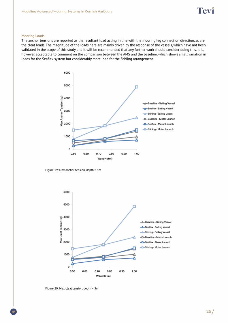
Mooring LoadsThe anchor tensions are reported as the resultant load acting in line with the mooring leg connection direction, as are the cleat loads. The magnitude of the loads here are mainly driven by the response of the vessels, which have not been validated in the scope of this study and it will be recommended that any further work should consider doing this. It is, however, acceptable to comment on the comparison between the AMS and the baseline, which shows small variation in loads for the Seaflex system but considerably more load for the Stirling arrangement.
Figure 19: Max anchor tension, depth = 3m
Figure 20: Max cleat tension, depth = 3m

26
Modeling Advanced Mooring Systems in Cornish Harbours
9.2. Water Depth = 5m
This water depth represents the deeper moorings at Falmouth and St. Mawes.
Mooring StiffnessThe following plots show the theoretical stiffness of the mooring arrangements generated in OrcaFlex by performing a simulation in which the vessel has been pulled away from the anchor (with no influence from environmental loads) in order to report the relationship between the force in the surface line and the vessel excursion in surge. The study shows that the Stirling system has greater force at the same excursion than the Seaflex system, possessing greater stiffness.
Figure 21: Mooring stiffness plots (left: 5m depth, right: +6m tidal elevation)

27
Modeling Advanced Mooring Systems in Cornish Harbours
ExcursionsThe graph below shows the maximum horizontal excursion of the vessels when connected to the AMS at the low tide condition (providing greater excursions than the high tide condition). As stated above it is accepted that the baseline catenary chain length is unknown, so this comparison must be treated with caution, however it is clear that there will be saving in watch circle as there is no requirement for ground chain for any of the AMS.
Figure 22: Max vessel excursion, depth = 5m

28
Modeling Advanced Mooring Systems in Cornish Harbours
Vessel MotionsIn general, the response of the vessel when connected to the AMS was very similar to that of the baseline. The plots below show a snapshot of time from the motor launch at 5m water depth with Hs=0.5m and Tp=4.4s, a case that is anticipated occur frequently. The heave and pitch show good correlation between the AMS and the baseline, there are some events when the Stirling system shows slightly greater surge response.
Figure 23: Time-history vessel motions (top: surge, middle: heave, bottom: pitch)
29
Modeling Advanced Mooring Systems in Cornish Harbours
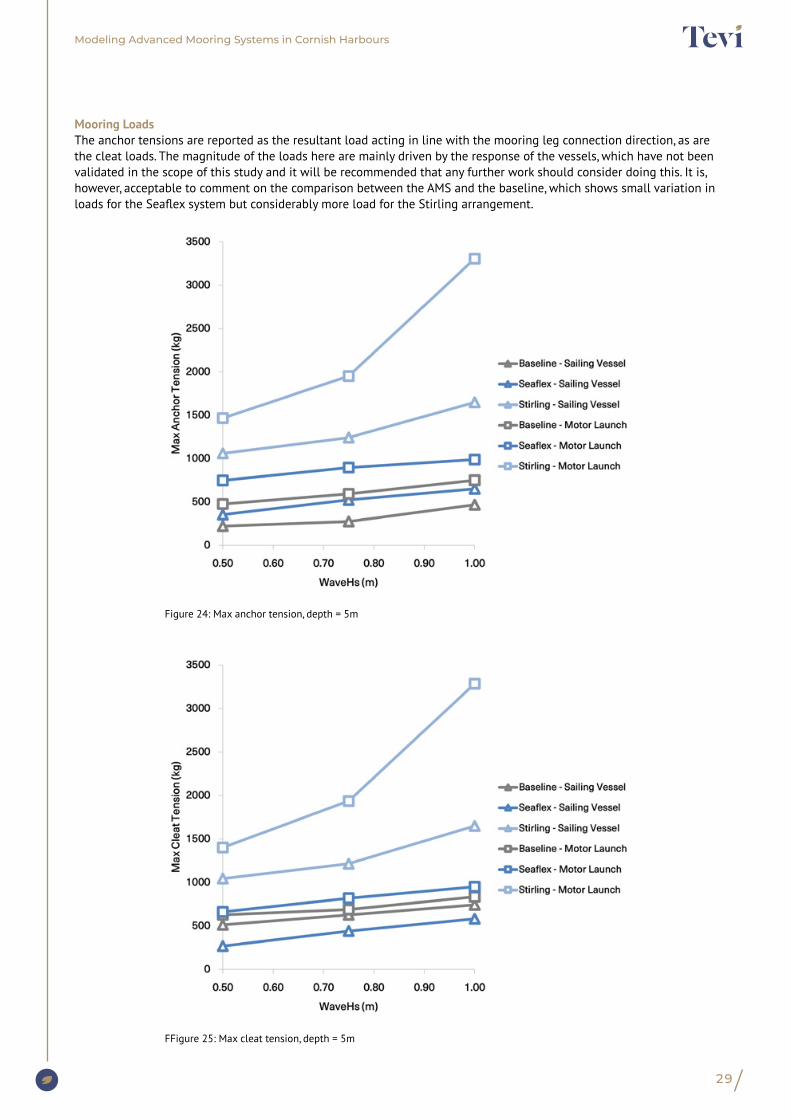
Mooring LoadsThe anchor tensions are reported as the resultant load acting in line with the mooring leg connection direction, as are the cleat loads. The magnitude of the loads here are mainly driven by the response of the vessels, which have not been validated in the scope of this study and it will be recommended that any further work should consider doing this. It is, however, acceptable to comment on the comparison between the AMS and the baseline, which shows small variation in loads for the Seaflex system but considerably more load for the Stirling arrangement.
Figure 24: Max anchor tension, depth = 5m
FFigure 25: Max cleat tension, depth = 5m
30
Modeling Advanced Mooring Systems in Cornish Harbours
9.3. Comparison to Baseline
The biggest complication found in the study was overcoming the challenging high tidal range observed in all Cornish harbours, especially when also combined with shallow overall charted depths.
The loads on the anchors and cleats are equivalent and, in some cases, lower for the Seaflex system, which was anticipated by the manufactures and is likely due to the dampening nature of the elastic components. The maximum load seen on the anchors is c.800kg for the Seaflex, consistent with the baseline.
The anomaly here is the Stirling system, which is seen to inflict over 5000kg at both anchor and vessel cleat. This result should be treated with caution, prior to validation of the hydrodynamic analysis required to characterise the example vessels. It is logical to state that as the Stirling mooring possesses less of a spring effect when compared to the catenary mooring and indeed the elastic Seaflex, so a higher magnitude of loading may be anticipated.
A further characteristic of the study to assess and investigate the effect on the sensitivity of the results is the definition of seastate. The models have been run with a specific irregular seastate spectrum, the Pierson Moskovitz spectra, the most used deep-water sea spectrum. It should be noted that the depths in this study are very shallow and as such it is likely that a more appropriate spectra could be used, even a regular or monochromatic sea state. It is important to note that the most effective and precise way of obtaining quantified data for this type of mooring will be through a fully instrumented sea trial campaign.
Screw anchors have very clear benefits to the seabed habitat as described above and are well suited to the AMS systems simulated.
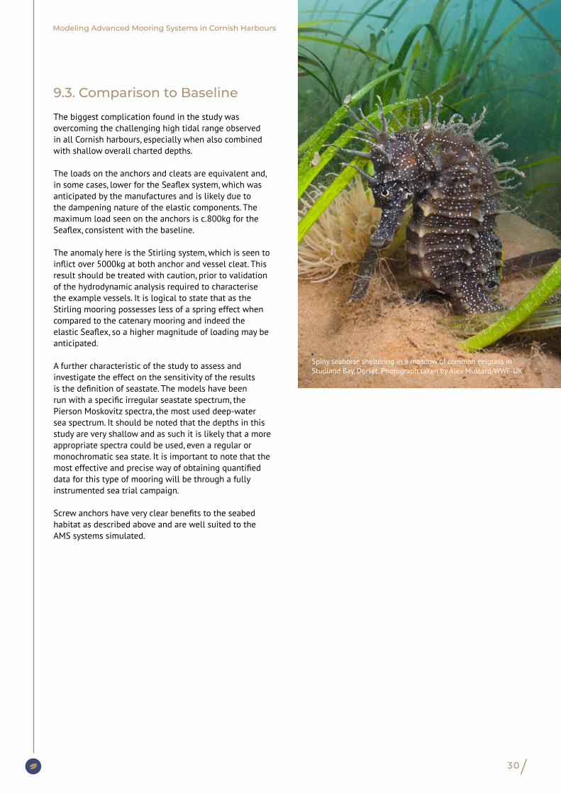
Spiny seahorse sheltering in a meadow of common eelgrass in Studland Bay, Dorset. Photograph taken by Alex Mustard/WWF-UK
Modeling Advanced Mooring Systems in Cornish Harbours
The numerical modelling has been undertaken with the marine dynamics software Orcaflex, the world’s leading package for the dynamic analysis of offshore marine systems, regularly used for the design and analysis of moorings.
Dynamic simulations were run in OrcaFlex software, for each of the load cases selected. Models were generated for each of the AMS arrangements in the OrcaFlex user interface, capturing the following attributes of the systems:
• Vessel response characteristics: from the diffraction analysis detailed above.
• Behaviour of the buoys: hydrostatics and hydrodynamics.
• Behaviour of the chain and synthetic lines: structural stiffness and hydrodynamics.
• The anchor is assumed as fixed, with the end of the line attached to a point on the seabed, the loads will be reported for consideration of anchoring technologies.
The dynamic simulations were run for 3600seconds (60 minutes). The following environmental conditions were applied:
• Tidal current and wind: applied as a constant static load on the vessel and mooring components.
• Wave conditions: Pierson Moskovitz wave spectra with peak shape parameter, γ = 1, the same seed has been used for each environmental case throughout, resulting in identical wave trains for each mooring arrangement.
8. Simulation
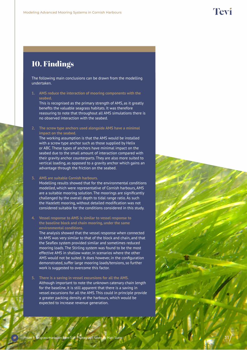
The following main conclusions can be drawn from the modelling undertaken.
1. AMS reduce the interaction of mooring components with the seabed. This is recognised as the primary strength of AMS, as it greatly benefits the valuable seagrass habitats. It was therefore reassuring to note that throughout all AMS simulations there is no observed interaction with the seabed.
2. The screw type anchors used alongside AMS have a minimal impact on the seabed. The working assumption is that the AMS would be installed with a screw type anchor such as those supplied by Helix or ABC. These types of anchors have minimal impact on the seabed due to the small amount of interaction compared with their gravity anchor counterparts. They are also more suited to vertical loading, as opposed to a gravity anchor which gains an advantage through the friction on the seabed.
3. AMS are suitable Cornish harbours. Modelling results showed that for the environmental conditions modelled, which were representative of Cornish harbours, AMS are a suitable mooring solution. The moorings are significantly challenged by the overall depth to tidal range ratio. As such the Hazelett mooring, without detailed modification was not considered suitable for the conditions considered in this study.
4. Vessel response to AMS is similar to vessel response to the baseline block and chain mooring, under the same environmental conditions. The analysis showed that the vessel response when connected to AMS was very similar to that of the block and chain, and that the Seaflex system provided similar and sometimes reduced mooring loads. The Stirling system was found to be the most effective AMS in shallow water, in scenarios where the other AMS would not be suited. It does however, in the configuration demonstrated, suffer large mooring loads/tensions, so further work is suggested to overcome this factor.
5. There is a saving in vessel excursions for all the AMS. Although important to note the unknown catenary chain length for the baseline, it is still apparent that there is a saving in vessel excursions for all the AMS. This could in principle provide a greater packing density at the harbours, which would be expected to increase revenue generation.
10. Findings
31Photo 9. Eelgrass marazion from SUP. Photograph taken by Matt Slater.

Modeling Advanced Mooring Systems in Cornish Harbours
32
Photo 10. Isles of Scilly seagrass. Photograph taken by Fiona Crouch, Natural England.
The scope of this desktop study has been to conduct a preliminary numerical comparison between AMS technologies and the traditional block and chain mooring. The study is not without its limitations and it is recommended that the work should be accompanied with fully instrumented practical testing either at model scale in a wave tank such as the University of Plymouth COAST facility or full-scale sea trials to validate the assumptions of the work.
It is important to note the vessels considered in this study are at the largest end of typical moored craft at the surveyed. Further work should include consideration of smaller vessels also.In addition, ideally post validation activities it is suggested that further optimisation is undertaken on the composition of each mooring. It is recommended that this can be achieved with further formal engagement with the suppliers. There remains potential to refine arrangements and unlock further potential for reducing peak loads in the mooring systems.
Input environmental conditions have been generated through interview and judgement. It would be preferable to undertake an oceanographic measurement campaign to acquire real life conditions at any specific sites which may further investigate the deployment of AMS.
Finally, there were some interesting additional issues that arose during conversations with the harbours into which it may be valuable to gain further insight. That is to consider the implementation of AMS with consideration of a full picture of environmental, social, and economic impact, potentially in the form of a cost-benefit analysis. For example, harbours are equipped and experienced in maintenance of traditional moorings but would be unable to service AMS without additional equipment or use of a specialist diver, therefore impacting on running costs. Any additional fees passed onto boat owners may affect the affordability of the moorings, with the concern being affordability for local users and potentially limiting their ability to access their local environment.
11. Recommendations

33
Modeling Advanced Mooring Systems in Cornish Harbours
12. References1. Tevi; “The decline of UK seagrass habitats and the importance of advanced mooring systems”; May 2020
2. FabTest; Website: https://www.fabtest.com/characteristics; Last accessed: 10/11/2020
13. Abbreviations
ABC Helical pile supplier
AMS Advanced Mooring System
BOM Bill Of Materials
LCB Longitudinal Centre of Buoyancy
RPT Report
VCB Vertical Centre of Buoyancy
VCG Vertical Centre of Gravity

34
Modeling Advanced Mooring Systems in Cornish Harbours
1. Appendix A – Beaufort Scale
2. Appendix B – Reference vessel detailsThe table below shows a breakdown of the vessel input parameters used in the analysis.
Table 8: Vessel input parameters
Parameter Description Vessel 1 – Motor Launch
Vessel 2 – Sailing yacht Units
Length Length (Overall) 10.2 12 m
Beam Molded Beam 4.22 3.375 m
Draft Baseline to waterline vertical length 0.8 2 m
Cb Block Coefficient 0.3398 0.103 n.d
Δ Displacement Mass displacement 10.09 6.037 m3
Displacement Volumetric displacement 9.845 5.889 m
VCB Vertical Centre Of Buoyancy 0.578 1.762 m
LCB Longitudinal Centre of Buoyancy 4.019 5.678 m
VCG Vertical Centre of Gravity 1.745 2.658 m
GMt Transverse Metacentric height 3.457 3.371 m
GMl Longitudinal metacentric height 15.438 19.975 m
Δ
Beaufort Wind Scale
Mean Wind Speed (knots)
Mean Wind Speed (m/s)
Limits of Wind Speed
(knots)
Limits of Wind Speed (m/s)
Wind Descriptive Terms
Probable Wave
Height (m)
Probable Max Wave Height (m)
Seastate Sea Descriptive Terms
0 0 0 <1 <1 Calm - - 0 Calm (glassy)
1 2 1 1-3 1-2 Light air 0.1 0.1 1 Calm (rippled)
2 5 3 4-6 2-3 Light breeze 0.2 0.3 2 Smooth (wavelete)
3 9 5 7-10 4-5 Gentle breeze 0.6 1 3 Slight
4 13 7 11-16 6-8 Moderate breeze 1 1.5 3-4 Moderate
5 19 10 17-21 9-11 Fresh breeze 2 2.5 4 Rough
6 24 12 22-27 11-14 Srtong breeze 3 4 5 Rough - Very rough
7 30 15 28-33 14-17 Near gale 5 5.5 5-6 Very rough - High
8 37 19 24-40 17-21 Gale 6 7.5 6-7 High
9 44 23 41-47 21-24 Strong gale 7 10 7 Very High
10 52 27 48-55 25-28 Storm 9 12.5 8 Very High
11 60 31 56-63 29-32 Violent storm 12 16 8
12 - 6 64+ 33+ Hurricane 14+ - 0 18.5

35
Modeling Advanced Mooring Systems in Cornish Harbours
3. Appendix C - Vessel RAOsThe below show the displacement RAOs (at 0deg wave heading) for each vessel.
Figure 26: Motor launch displacement RAOs at 0deg
Figure 27: Sailing yacht displacement RAOs at 0deg
36
Modeling Advanced Mooring Systems in Cornish Harbours
Publication date: March 2021
Contributors:This report was produced by Morek Engineering and commissioned by Tevi. Morek (Maritime in Cornish) is a consultancy combining naval architecture and marine engineering skills to offer high quality, detailed technical services to all aspects of the blue economy. Involvement in Advanced Mooring Systems (AMS) aligns with Morek’s vision of using engineering skills to both reduce the harmful exploitation and increase the sustainable use of the seas. Whilst the scale and specific application to boating in the leisure industry is relatively new to Morek, this work has benefited from their extensive track record in larger marine renewables (including wave, tide and offshore wind energy) and in particular their use of marine dynamics software, Orcaflex. Morek are looking forward to further their involvement in AMS deployment and would be happy to hear from interested parties ([email protected]).
Designed by Eight Wirewww.eightwire.uk
Communications: www.tevi.co.uk
@TeviCornwall
Photo 11. Seagrass. Photograph taken by Fiona Crouch, Natural England.