세계음식문화 표지 10권 수정 - The ChoiceMaker · 글김영 대학에서심리학을공부하고, 어린이독서프로그램을개발하면서동화를쓰기시작했습니다.

SSSDDDRRR111000000 --- SSSEEERRRIIIEEESSSSDR102, SDR104, SDR106, SDR112
Communication
Manual Digital Recorder

SAMWONTECH
1st Edition of SDR100_Series IM : Feb. 01. 2010 1 / 1
※ This Manual applies to SDR102, SDR104, SDR106, SDR112.
The model stated the manual content is SDR112.
Table of Contents
1. Instruction (Warning) on Safety................................................................................................................. 1
2. Communication Specification.................................................................................................................... 3
3. Communication Wiring....................................................................................................................................4
4. Communication Command...........................................................................................................................5
5. MODBUS Protocol............................................................................................................................................ 16
6. D-REGISTER Description.............................................................................................................................. 22
■ D-REGISTER Table............................................................................................................................................ 34
SAMWONTECH
1st Edition of SDR100_Series IM : Feb. 01. 2010 Page 1 / 47
1. Instruction (Warning) on Safety Thanks a lot for purchasing our Digital Recorder (SDR112).
This Communication Manual describes how to install and operate the product.
SAFETY SYMBOL MARK
(A) Indicates “Handle with Care” or “Caution”. Violation to the instruction may cause
death, serious injury or serious damage to the product.
(1) Product: Appears when the item shall be well aware to protect human body
and product.
(2) Communication Manual: Caution is indicated to prevent danger to user life
and body when it is concerned.
(B) Indicates “Ground Terminal”.
Must make Ground to earth during installation and operation.
(C) Indicates “Additional Information”.
It describes additional information for the explanation.
(D) Indicates “Reference”.
☞ It describes items to reference and referencing page.
Caution for this Communication Manual ㅇ
(A) Hand this Communication Manual to final User to carry with always, and store it
nearby to reference anytime when needed.
(B) Use this product when you are fully acquainted with the Communication Manual.
(C) This Manual explains the detailed functions of the product, and it does not guaranty
any other items except the Communication Manual.
(D) It is not allowed to edit or copy part or all of this Communication Manual without
permission.
(E) The contents of this Manual may be changed without prior information or advanced
notice.
(F) This Manual is prepared with the best knowledge, but please contact the company
you purchase (Distributor) or our Sales Department if there is insufficient, wrong or
missing item.

SAMWONTECH
1st Edition of SDR100_Series IM : Feb. 01. 2010 Page 2 / 47
Caution for Safety & Modify(Change) of this Product
(A) For the safety of this product and the system to be connected to the product, use
the product after fully aware the Safety Warnings (Instruction) in the Communication
Manual.
(B) Our company does not have responsibility for any damage caused by using handling
different from the Communication Manual, or damage from carelessness.
(C) For the protection and safety purpose of this product and the system connected to
this product, extra protection or safety circuit must be installed outside the product.
It is prohibited to modify (change) or add inside the product.
(D) Do not arbitrary disassemble, repair or modify. It can be the cause of electric shock,
fire or malfunction.
(E) Please contact our Sales Department when changing the part or expendable items.
(F) Prevent moisture from entering the equipment. It may be the cause of trouble.
(G) Prevent strong shock to the product. It may be the cause of product damage or
malfunction.
Regarding Warranty for the Product
(A) Our company does not have any warranty of responsibility except the items specified
in our Quality Assurance condition.
(B) Our company does not have any responsibility for any direct or indirect damage to
the User or the third party due to unpredictable fault and natural disaster in using the
Product.
Regarding the Product Quality Assurance
(A) Product Warranty Period is one year from the date of purchase. It will be repaired
free of charge for fault happened during normal operation according to the
Communication Manual.
(B) Repair for product problem after the warranty period will be charged (actual expense)
according to our company standard.
(C) Following troubles will be charged even within the warranty period.
(1) Trouble due to User mistake or error (Ex: Initialization due to lost Password, etc)
(2) Trouble due to natural disaster (Ex: Fire, Flood, etc.)
(3) Trouble due to transfer of the product after installation.
(4) Trouble due to arbitrary product disassemble, modify or damage
(5) Trouble due to power trouble such as unstable power, etc.
(6) Others
(D) Please contact the company you purchased (Distributor) or our Sales Department
when you need A/S due to product trouble.

SAMWONTECH
1st Edition of SDR100_Series IM : Feb. 01. 2010 Page 3 / 47
2. Communication Specification
Communication of SDR112 is made through RS485 type 2-wire Half-Duplex, and it is able to connect
up to 30 devices with upper level computers using the prepared Protocol.
▶ Communication Setup related Parameter
Parameter Setup Range Default Value
PCLINK Basic Protocol
PCLINK+SUM Basic Protocol + CheckSum
MODBUS ASC MODBUS ASCII
PROTOCOL
MODBUS RTU MODBUS RTU
9600 9600 bps
19200 19200 bps
38400 38400 bps
57600 57600 bps
BAUD RATE
115200 115200 bps
NONE No Parity
EVEN Even Parity PARITY
ODD Odd Parity
1 1 bit
STOP BIT
2 2 bits
7 7 bits
DATA LENGTH
8 8 bits
EQUIPMENT ADDRESS 1~99 Equipment Address
RESPONSE TIME 0~10 Response Time (= Process Time + RESPONSE
TIME * 10msec)
▶ Default Communication Parameter Value at factory output condition
● PROTOCOL PCLINK+SUM (PCLINK+CheckSum)
● Baud Rate (BPS) 9600 bps
● PARITY NONE
● STOP BIT 1 (1 bit)
● DATA LENGTH 8 (8 bit)
● Equipment Address 1
● RESPONSE TIME 0 (Process Time + 10 msec)

SAMWONTECH
1st Edition of SDR100_Series IM : Feb. 01. 2010 Page 4 / 47
3. Communication Wiring
▶ Wiring between SDR112 and upper level communication equipment is different according to
communication setup (RS232C/RS485), and it is as follows.
▶ SDR112 6 Pin Connector connection in RS232C Communication
▶ SDR112 Terminal Connection in RS485 Communication
○
SDR112 Master
Shielded Communication Cable
TxD
RxD
SG
SHIELD
② RD
③ TD
⑦ RTS
⑧ CTS
⑤ SG
RTX(+)
TXD RTX(-)
RXD
SG
(Comm. Option)
RTX+
RTX-
SG
Master Station
Shielded Communication Cable
SDR112SDR112
RTX+
RTX-
SG
RTX+
RTX-
SG

SAMWONTECH
1st Edition of SDR100_Series IM : Feb. 01. 2010 Page 5 / 47
4. Communication Command
4.1 Configuration of Communication Command
▶ Basic format of communication command transferred from upper level communication device to
SDR112 is as follows.
① ② ③ ④ ⑤ ⑥ ⑦ ⑧
STX SDR112 Address Command , Data according to
Command rule SUM CR LF
① Communication Command Start Character
▪ STX(Start of Text) in ASCII, code value is 0x02, and indicates start of communication
command.
② SDR112 Address
▪ Indicates Unit Address which is SDR112 device number to communicate.
③ Command
▪ Command to communicate (Refer to Article 4.2 ~ 4.10).
④ Separator
▪ Comma (‘,’). It separates command and data.
⑤ Data Part
▪ Specific type characters according to communication command.
⑥ SUM
▪ Add characters after STX until before SUM in ASCII code, and transform the lower 1 byte (8
bit) into ASCII code 2 digit (Hexadecimal).
⑦ / ⑧ Terminating Character
▪ ASCII code which indicates the end of command, and is indicated as CR(0x0D), LF(0x0A).
SAMWONTECH
1st Edition of SDR100_Series IM : Feb. 01. 2010 Page 6 / 47
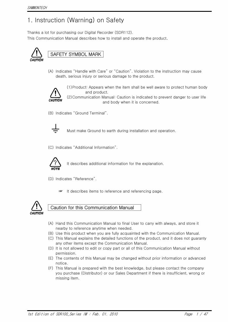
▶ Example of SUM
◈ Example
When reading D-Register from CH1.NPV(D0001) to CH6.NPV(D0006)
- Transmit : [stx]01RSD,06,0001[cr][lf]
- Transmit (Including CheckSum) .: [stx]01RSD,06,0001C9[cr][lf]
☞ As shown is following, hexadecimal sum of 01RSD,06,0001 in ASCII is 2C9, and take lower 2
byte C9 and use it as CheckSum.
Character 0 1 R S D , 0 6 , 0 0 0 1
ASCII
Value 30 31 52 53 44 2C 30 36 2C 30 30 30 31
▶ ASCII Code
2nd 1st 0 1 2 3 4 5 6 7
0 MUL DLE SPACE 0 @ P ` p
1 S0H DC1 ! 1 A Q a q
2 STX DC2 “ 2 B R b r
3 ETX DC3 # 3 C S c s
4 E0T DC4 $ 4 D T d t
5 ENQ NAK % 5 E U e u
6 ACK SYN & 6 F V f v
7 BEL ETB ` 7 G W g w
8 BS CAN ( 8 H X h x
9 HT EM ) 9 I Y i y
A LF SUB * : J Z j z
B VT ESC + ; K [ k {
C FF FS , < L ¥ l |
D CR GS - = M ] m }
E S0 RS . > N ^ n ~
F SI US / ? O _ o DEL
+ 2C9

SAMWONTECH
1st Edition of SDR100_Series IM : Feb. 01. 2010 Page 7 / 47
4.2 Communication Command Types
▶ Two types of commands are provided on SDR112. One is general READ/WRITE command to
read and write information on D-Register, and the other is Reference command to read self-
information of SDR112.
▪ Reference Command
Command Description
AMI Indicate Model Name and Version-Revision of SDR112
▪ Read/Write Command
Command Description
RSD D-Register Sequential Read
RRD D-Register Random Read
WSD D-Register Sequential Write
WRD D-Register Random Write
STD D-Register Monitoring Set
CLD D-Register Monitoring Call
☞ Each command can read or write up to 64 D-Register. For STD/CLD, its registered contents
are initialized when power is off, and need to re-register when power on.

SAMWONTECH
1st Edition of SDR100_Series IM : Feb. 01. 2010 Page 8 / 47
4.3 Error Code
▶ SDR112 transmit as follows when error occurred during communication.
Number of
Byte 1 2 2 2 2 1 1
Contents STX SDR112
Address NG Error Code SUM CR LF
▪ Description of Error Code
Error Code Description Remark
01 Non-existing command assigned
02 Non-existing D-Register assigned
03 Quantity setup error
04 Data setup error Use character other than effective data
(Data use only 0~9, A~F hexadecimal)
08 Wrong Format configuration ▪ Different format from assigned command
▪ Assigned quantity is different from setup
11 CheckSum Error
12 Monitoring Command Error There is no assigned Monitoring Command
00 Other Error occurred

SAMWONTECH
1st Edition of SDR100_Series IM : Feb. 01. 2010 Page 9 / 47
4.4 RSD Command
▶ This command is used to read sequential data in D-Register.
▣ Transmit Format
Number
of Byte 1 2 3 1 2 1 4 2 1 1
Contents STX SDR112
Address RSD , Quantity , D-Reg. SUM CR LF
▣ Receiving Format
Number
of Byte 1 2 3 1 2 1 4 1 …
Contents STX SDR112
Address RSD , OK , Data-1 , …
1 4 2 1 1
, Data-n SUM CR LF
▪ Quantity : 1 ~ 64
▪ DATA : Hexadecimal number without decimal point
◈ Example
When reading D-Register from CH1.NPV(D0001) to CH2.NPV(D0002)
- Transmit : [stx]01RSD,02,0001[cr][lf]
- Transmit (including CheckSum) .: [stx]01RSD,02,0001C5[cr][lf]
When received CH1.NPV(D0001) is 50.0, CH2.NPV(D0002) is 30.0:
- Receive : [stx]01RSD,OK,01F4,012C[cr][lf]
- Receive (including CheckSum) .: [stx]01RSD,OK,01F4,012C19[cr][lf]
▶ Process to transform received NPV hexadecimal data value to display on the screen.
① Transform to decimal number: 01F4(hexadecimal) 500(decimal)
② Multiply 0.1 to transformed value. : 500 * 0.1 50.0

SAMWONTECH
1st Edition of SDR100_Series IM : Feb. 01. 2010 Page 10 / 47
4.5 RRD Command
▶ This command is used to read random data in D-Register.
▣ Transmit Format
Number
of Byte 1 2 3 1 2 1 4 1 …
Contents STX SDR112
Address RRD , Quantity , D-Reg.-1 , …
1 4 2 1 1
, D-Reg.-n SUM CR LF
▣ Receive Format
Number
of Byte 1 2 3 1 2 1 4 1 …
Contents STX SDR112
Address RRD , OK , Data-1 , …
1 4 2 1 1
, Data-n SUM CR LF
▪ Quantity : 1 ~ 64
▪ DATA : Hexadecimal number without decimal point
◈ Example
When reading D-Register of CH1.NPV(D0001) and CH2.NPV(D0002):
- Transmit : [stx]01RRD,02,0001,0002[cr][lf]
- Transmit (including CheckSum) .: [stx]01RRD,02,0001,0002B2[cr][lf]
When received CH1 (D0001) value is 50.0, CH2 (D0002) value is 30.0:
- Receive : [stx]01RRD,OK,01F4,012C[cr][lf]
- Receive (including CheckSum) .: [stx]01RRD,OK,01F4,012C18[cr][lf]
SAMWONTECH
1st Edition of SDR100_Series IM : Feb. 01. 2010 Page 11 / 47
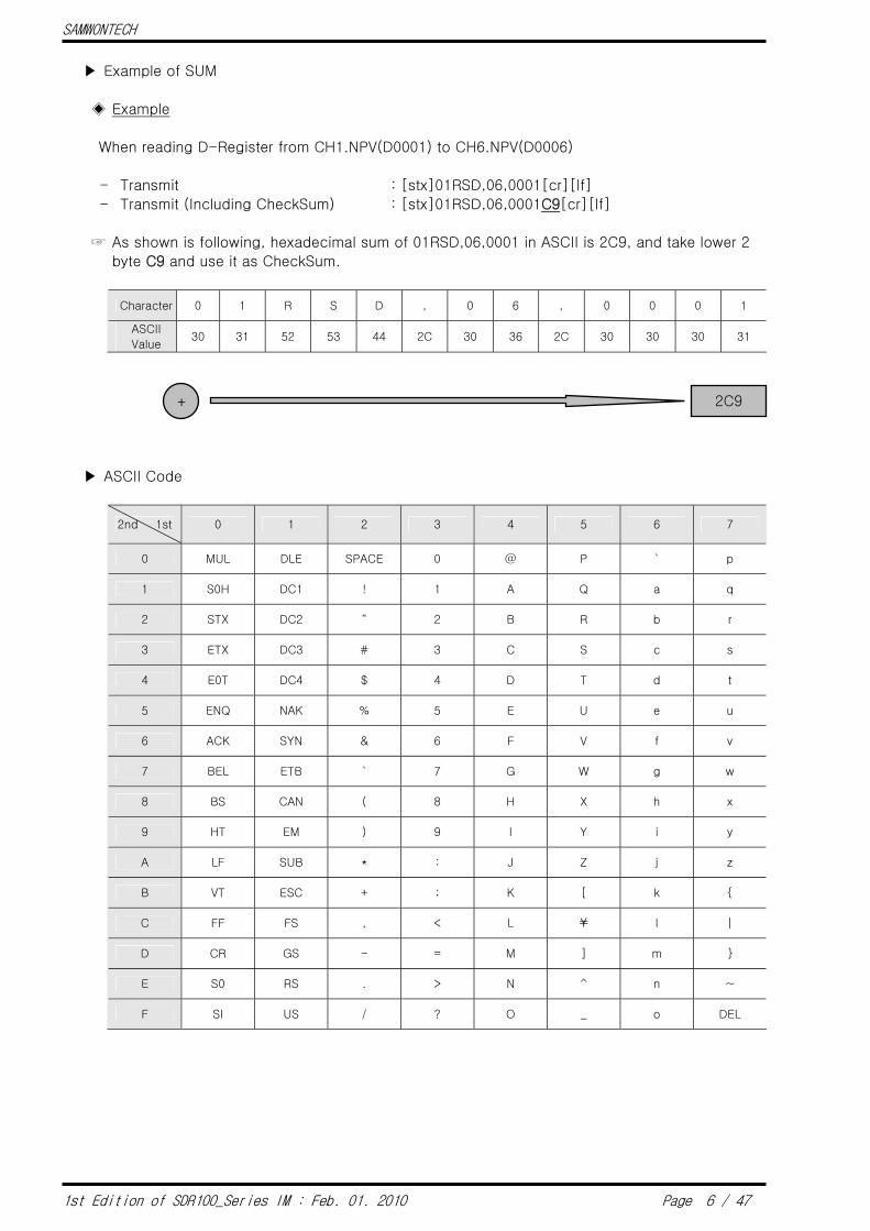
4.6 WSD Command
▶ This command is used sequential data to D-Register.
▣ Transmit Format
Number
of Byte 1 2 3 1 2 1 4 1 4
Contents STX SDR112
Address WSD , Quantity , D-Reg. , Data-1
1 … 1 4 2 1 1
, … , Data-n SUM CR LF
▣ Receive Format
Number
of Byte 1 2 3 1 2 2 1 1
Contents STX SDR112
Address WSD , OK SUM CR LF
▪ Quantity : 1 ~ 64
▪ DATA : Hexadecimal number without decimal point
◈ Example
When writing data to First Cycle (D0102) and Second Cycle (D0103) of Recording Cycle.
- First Cycle Set Value : 0 (0.5 Sec)
- Second Cycle Set Value : 1 (1Sec)
- Transmit : [stx]01WSD,02,0102,0000,0001[cr][lf]
- Transmit (including CheckSum) .: [stx]01WSD,02,0102,0000,0001A5[cr][lf]

SAMWONTECH
1st Edition of SDR100_Series IM : Feb. 01. 2010 Page 12 / 47
4.7 WRD Command
▶ This command is used to write Random Data to D-Register.
▣ Transmit Format
Number
of Byte 1 2 3 1 2 1 4 1 4
Contents STX SDR112
Address WRD , Quantity , D-Reg.-1 , Data-1
1 … 1 4 1 4 2 1 1
, … , D-Reg.-n , Data-n SUM CR LF
▣ Receive Format
Number
of Byte 1 2 3 1 2 2 1 1
Contents STX SDR112
Address WRD , OK SUM CR LF
▪ Quantity : 1 ~ 64
▪ DATA : Hexadecimal number without decimal point
◈ Example
When writing data to First Cycle (D0102) and Second Cycle (D0103) of Recording Cycle.
- First Cycle Set Value : 0 (0.5 Sec)
- Second Cycle Set Value : 1 (1Sec)
- Transmit : [stx]01WRD,02,0102,0000,0103,0001[cr][lf]
- Transmit (including CheckSum) .: [stx]01WRD,02,0102,0000,0103,000194[cr][lf]
SAMWONTECH
1st Edition of SDR100_Series IM : Feb. 01. 2010 Page 13 / 47
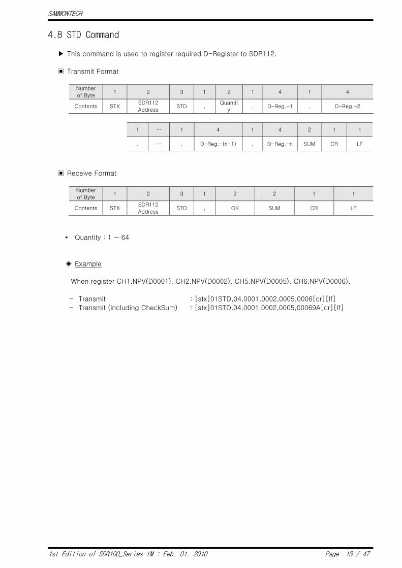
4.8 STD Command
▶ This command is used to register required D-Register to SDR112.
▣ Transmit Format
Number
of Byte 1 2 3 1 2 1 4 1 4
Contents STX SDR112
Address STD ,
Quantit
y , D-Reg.-1 , D-Reg.-2
1 … 1 4 1 4 2 1 1
, … , D-Reg.-(n-1) , D-Reg.-n SUM CR LF
▣ Receive Format
Number
of Byte 1 2 3 1 2 2 1 1
Contents STX SDR112
Address STD , OK SUM CR LF
▪ Quantity : 1 ~ 64
◈ Example
When register CH1.NPV(D0001), CH2.NPV(D0002), CH5.NPV(D0005), CH6.NPV(D0006).
- Transmit : [stx]01STD,04,0001,0002,0005,0006[cr][lf]
- Transmit (including CheckSum) .: [stx]01STD,04,0001,0002,0005,00069A[cr][lf]

SAMWONTECH
1st Edition of SDR100_Series IM : Feb. 01. 2010 Page 14 / 47
4.9 CLD Command
▶ This command is used to read pre-registered SDR112’s D-Register using STD command.
▣ Transmit Format
Number
of Byte 1 2 3 2 1 1
Contents STX SDR112 Address CLD SUM CR LF
▣ Receive Format
Number
of Byte 1 2 3 1 2 1 4 1 4
Contents STX SDR112
Address CLD , OK , Data-1 , Data-2
1 … 1 4 1 4 2 1 1
, … , Data-(n-1) , Data-n SUM CR LF
▪ Data : Hexadecimal number without decimal point

SAMWONTECH
1st Edition of SDR100_Series IM : Feb. 01. 2010 Page 15 / 47
4.10 AMI Command
▶ This command is used to check SDR112 information.
▣ Transmit Format
Number
of Byte 1 2 3 2 1 1
Contents STX SDR112 Address AMI SUM CR LF
▣ Receive Format
Number
of Byte 1 2 3 1 2 1
Contents STX SDR112 Address AMI , OK ,
7 3 8 2 1 1
Model Name SPACE Version Revision SUM CR LF
◈ Example
When checking SDR112 information:
- Transmit : [STX]01AMI[CR][LF]
- Transmit(including CheckSum) .: [STX]01AMI38[CR][LF]
- Receive : [STX]01AMI , OK, SDR[sp]112[sp][sp][sp]V00[sp]R0.1[cr][lf]
- Receive(including CheckSum): [STX]01AMI, OK, SDR[sp]112[sp][sp][sp]V00[sp]R0.1DE[cr][lf]

SAMWONTECH
1st Edition of SDR100_Series IM : Feb. 01. 2010 Page 16 / 47
5. MODBUS Protocol
5.1 Communication Command Configuration
▣ Data Format
Item ASCII RTU
Communication Leading Character : (Colon) None
Communication Terminating
Character [CR][LF] none
Data Length 7-bit(fixed) 8-bit(fixed)
Data Format ASCII Binary
Error Detection LRC
(Longitudinal Redundancy Check)
CRC-16
(Cyclic Redundancy Check)
Data Timing Difference Less than 1 sec. Less than 24-bit time
▣ Frame Configuration
▶ Modbus ASCII
Leading
Character
Communication
Address Function Code Data LRC Check
Terminating
Character
1 Character 2 Character 2 Character N Character 2 Character 2 Character
(CR+LF)
▶ Modbus RTU
Leading
Character
Communication
Address Function Code Data LRC Check
Terminating
Character
None 8-bit 8-bit N * 8-bit 16-bit None
▪ N : Hexadecimal Data Quantity

SAMWONTECH
1st Edition of SDR100_Series IM : Feb. 01. 2010 Page 17 / 47
5.2 Communication Function Code
▶ Modbus Communication Code consists of D-Register Read/Write Function Code and Loop-
Back Detection Function Code.
Function Code Description
03 Sequential Read from D-Register
06 Single Write to D-Register
08 Diagnostics (Loop-Back Test)
16 Sequential Write to D-Register
When using MODBUS protocol, it should apply 1 number less D-Register
number than what is defined in D-Register Table since D-Register number
starts from 0.
SAMWONTECH
1st Edition of SDR100_Series IM : Feb. 01. 2010 Page 18 / 47
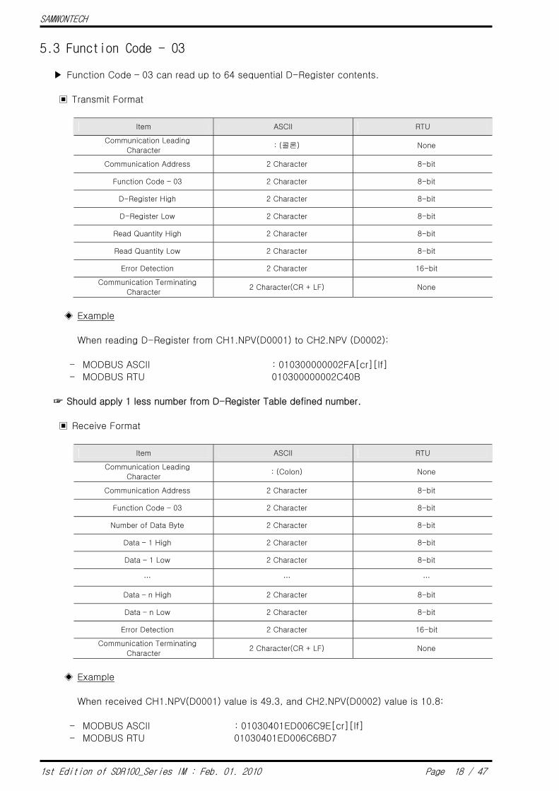
5.3 Function Code - 03
▶ Function Code – 03 can read up to 64 sequential D-Register contents.
▣ Transmit Format
Item ASCII RTU
Communication Leading
Character : (콜론) None
Communication Address 2 Character 8-bit
Function Code – 03 2 Character 8-bit
D-Register High 2 Character 8-bit
D-Register Low 2 Character 8-bit
Read Quantity High 2 Character 8-bit
Read Quantity Low 2 Character 8-bit
Error Detection 2 Character 16-bit
Communication Terminating
Character 2 Character(CR + LF) None
◈ Example
When reading D-Register from CH1.NPV(D0001) to CH2.NPV (D0002):
- MODBUS ASCII : 010300000002FA[cr][lf]
- MODBUS RTU 010300000002C40B
☞ Should apply 1 less number from D-Register Table defined number.
▣ Receive Format
Item ASCII RTU
Communication Leading
Character : (Colon) None
Communication Address 2 Character 8-bit
Function Code – 03 2 Character 8-bit
Number of Data Byte 2 Character 8-bit
Data – 1 High 2 Character 8-bit
Data – 1 Low 2 Character 8-bit
… … …
Data – n High 2 Character 8-bit
Data – n Low 2 Character 8-bit
Error Detection 2 Character 16-bit
Communication Terminating
Character 2 Character(CR + LF) None
◈ Example
When received CH1.NPV(D0001) value is 49.3, and CH2.NPV(D0002) value is 10.8:
- MODBUS ASCII : 01030401ED006C9E[cr][lf]
- MODBUS RTU 01030401ED006C6BD7

SAMWONTECH
1st Edition of SDR100_Series IM : Feb. 01. 2010 Page 19 / 47
5.4 Function Code - 06
▶ Function Code – 06 is used to write single D-Register contents.
▣ Transmit Format
Item ASCII RTU
Communication Leading
Character : (Colon) None
Communication Address 2 Character 8-bit
Function Code – 06 2 Character 8-bit
D-Register High 2 Character 8-bit
D-Register Low 2 Character 8-bit
Write Data High 2 Character 8-bit
Write Data Low 2 Character 8-bit
Error Detection 2 Character 16-bit
Communication Terminating
Character 2 Character(CR + LF) None
◈ Example
When set all ‘1’ to recovery from power outage (D0101):
- MODBUS ASCII :01060064000194[cr][lf]
- MODBUS RTU 01060064000109D5
☞ Should apply 1 less number from D-Register Table defined number.
▣ Receive Format
Item ASCII RTU
Communication Leading
Character : (Colon) None
Communication Address 2 Character 8-bit
Function Code – 06 2 Character 8-bit
D-Register High 2 Character 8-bit
D-Register Low 2 Character 8-bit
Write Data High 2 Character 8-bit
Write Data Low 2 Character 8-bit
Error Detection 2 Character 16-bit
Communication Terminating
Character 2 Character(CR + LF) None
◈ Example
When it is set correctly, it receives as follows:
- MODBUS ASCII :01060064000194[cr][lf]
- MODBUS RTU 01060064000109D5

SAMWONTECH
1st Edition of SDR100_Series IM : Feb. 01. 2010 Page 20 / 47
5.5 Function Code - 08
▶ Function Code – 08 is used for self diagnosis.
▣ Transmit Format
Item ASCII RTU
Communication Leading
Character : (Colon) None
Communication Address 2 Character 8-bit
Function Code – 08 2 Character 8-bit
Diagnose Code High 2 Character 8-bit
Diagnose Code Low 2 Character 8-bit
Data High 2 Character 8-bit
Data Low 2 Character 8-bit
Error Detection 2 Character 16-bit
Communication Terminating
Character 2 Character(CR + LF) None
◈ Example
When transmit following frame for self diagnosis:
- MODBUS ASCII :010800000002F5[cr][lf]
- MODBUS RTU 01080000000261CA
▣ Receive Format
Item ASCII RTU
Communication Leading
Character : (Colon) None
Communication Address 2 Character 8-bit
Function Code – 16 2 Character 8-bit
Diagnose Code High 2 Character 8-bit
Diagnose Code Low 2 Character 8-bit
Data High 2 Character 8-bit
Data Low 2 Character 8-bit
Error Detection 2 Character 16-bit
Communication Terminating
Character 2 Character(CR + LF) None
◈ Example
When it is set correctly, it receives as follows:
- MODBUS ASCII :010800000002F5[cr][lf]
- MODBUS RTU 01080000000261CA
SAMWONTECH
1st Edition of SDR100_Series IM : Feb. 01. 2010 Page 21 / 47
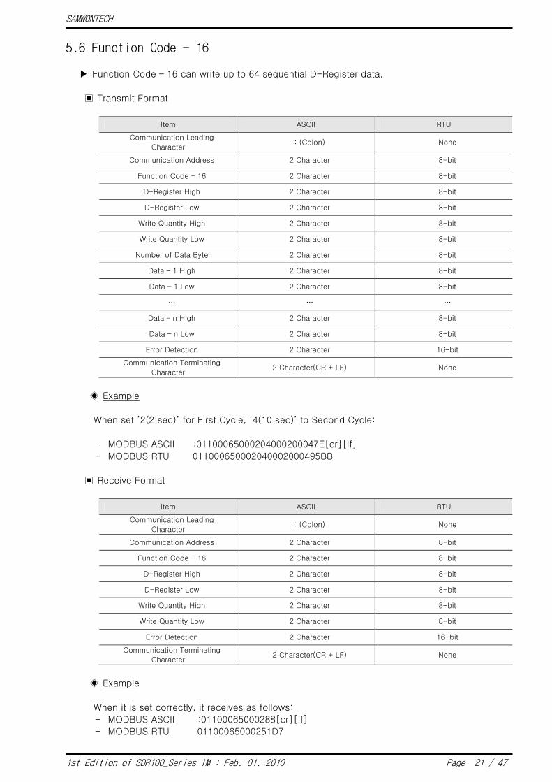
5.6 Function Code - 16
▶ Function Code – 16 can write up to 64 sequential D-Register data.
▣ Transmit Format
Item ASCII RTU
Communication Leading
Character : (Colon) None
Communication Address 2 Character 8-bit
Function Code – 16 2 Character 8-bit
D-Register High 2 Character 8-bit
D-Register Low 2 Character 8-bit
Write Quantity High 2 Character 8-bit
Write Quantity Low 2 Character 8-bit
Number of Data Byte 2 Character 8-bit
Data – 1 High 2 Character 8-bit
Data – 1 Low 2 Character 8-bit
… … …
Data – n High 2 Character 8-bit
Data – n Low 2 Character 8-bit
Error Detection 2 Character 16-bit
Communication Terminating
Character 2 Character(CR + LF) None
◈ Example
When set ’2(2 sec)’ for First Cycle, ‘4(10 sec)’ to Second Cycle:
- MODBUS ASCII :01100065000204000200047E[cr][lf]
- MODBUS RTU 011000650002040002000495BB
▣ Receive Format
Item ASCII RTU
Communication Leading
Character : (Colon) None
Communication Address 2 Character 8-bit
Function Code – 16 2 Character 8-bit
D-Register High 2 Character 8-bit
D-Register Low 2 Character 8-bit
Write Quantity High 2 Character 8-bit
Write Quantity Low 2 Character 8-bit
Error Detection 2 Character 16-bit
Communication Terminating
Character 2 Character(CR + LF) None
◈ Example
When it is set correctly, it receives as follows:
- MODBUS ASCII :01100065000288[cr][lf]
- MODBUS RTU 01100065000251D7

SAMWONTECH
1st Edition of SDR100_Series IM : Feb. 01. 2010 Page 22 / 47
6. D-Register Description
▶ D-Register is collection of data provided to check all the status of SDR112 through
communication.
▪ It is basically grouped with 100 registers according to their contents as follows:
D-Register Range Group Name Contents Read Write
D0001 ~ D0099 PROCESS Display Basic Record Information ○ ◈
D0101 ~ D0199 FUNCTION Set Record Information ○ ○
D0201 ~ D0330 DISPLAY Set Screen & Message ○ ○
D0334 ~ D0358 RESERVATION Set Clock Reserve Function ○ △
D0401 ~ D0599 INPUT Set Input ○ ○
D0901 ~ D0912 ALARM1 Set Alarm Operation ○ ○
D1001 ~ D2156 ALARM2 Set Alarm Signal ○ ○
D2201 ~ D2206 DICONFIG Set DI ○ ○
D2301 ~ D2319 COMMUNICATION Communication related Info ○ ◈
D2401 ~ D2403 PICTURE Set Picture View ○ ○
D2501 ~ D2544 INITIAL Set Initialization ○ ○
D2601 ~ D3314 ERROR HISTORY View Error History ○ ◈
D3401 ~ D4114 EVENT HISTORY View Event History ○ ◈
☞ Each D-Register is consisted of 4 hexadecimal digits (2-Byte).
▪ ○ : Able to read/write for all parameters in applicable range.
▪ △ : Able to read/write for partial parameters in applicable range.
▪ ◈ : Unable to write for any parameters in applicable range.

SAMWONTECH
1st Edition of SDR100_Series IM : Feb. 01. 2010 Page 23 / 47
6.1 PROCESS
▶ PROCESS Group stores basic data which occur during SDR112 recording. Among these, there
is Bit Map information which indicates various status to a Bit, and they are as follows.
▪ Bit Map Information of SDR112
NOW.STS CH1ALM.STS CH2ALM.STS CH3ALM.STS CH4ALM.STS BIT
D0016 D0020 D0021 D0022 D0023
0 RECORD ALM1 ALM1 ALM1 ALM1
1 SD.INSERT ALM2 ALM2 ALM2 ALM2
2 INTERVAL ALM3 ALM3 ALM3 ALM3
3 ALM4 ALM4 ALM4 ALM4
4
5
6
7
8
9
10
11
12
13
14
15
CH5ALM.STS CH6ALM.STS CH7ALM.STS CH8ALM.STS CH9ALM.STS BIT
D0024 D0025 D0026 D0027 D0028
0 ALM1 ALM1 ALM1 ALM1 ALM1
1 ALM2 ALM2 ALM2 ALM2 ALM2
2 ALM3 ALM3 ALM3 ALM3 ALM3
3 ALM4 ALM4 ALM4 ALM4 ALM4
4
5
6
7
8
9
10
11
12
13
14
15
SAMWONTECH
1st Edition of SDR100_Series IM : Feb. 01. 2010 Page 24 / 47
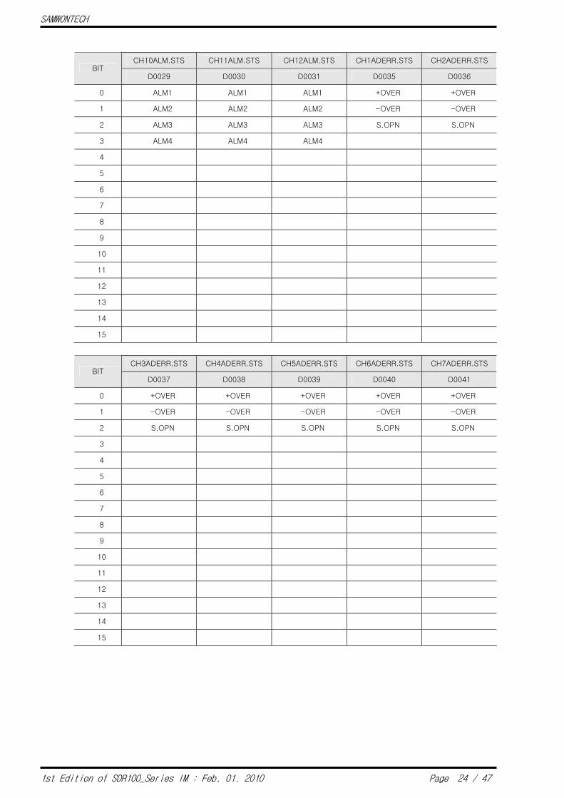
CH10ALM.STS CH11ALM.STS CH12ALM.STS CH1ADERR.STS CH2ADERR.STS BIT
D0029 D0030 D0031 D0035 D0036
0 ALM1 ALM1 ALM1 +OVER +OVER
1 ALM2 ALM2 ALM2 -OVER -OVER
2 ALM3 ALM3 ALM3 S.OPN S.OPN
3 ALM4 ALM4 ALM4
4
5
6
7
8
9
10
11
12
13
14
15
CH3ADERR.STS CH4ADERR.STS CH5ADERR.STS CH6ADERR.STS CH7ADERR.STS BIT
D0037 D0038 D0039 D0040 D0041
0 +OVER +OVER +OVER +OVER +OVER
1 -OVER -OVER -OVER -OVER -OVER
2 S.OPN S.OPN S.OPN S.OPN S.OPN
3
4
5
6
7
8
9
10
11
12
13
14
15

SAMWONTECH
1st Edition of SDR100_Series IM : Feb. 01. 2010 Page 25 / 47
CH8ADERR.STS CH9ADERR.STS CH10ADERR.STS CH11ADERR.STS CH12ADERR.STSBIT
D0042 D0043 D0044 D0045 D0046
0 +OVER +OVER +OVER +OVER +OVER
1 -OVER -OVER -OVER -OVER -OVER
2 S.OPN S.OPN S.OPN S.OPN S.OPN
3
4
5
6
7
8
9
10
11
12
13
14
15
ALARMOUT.STS REMOTINPUT.STS BIT
D0050 D0051
0 RELAY1 DI1
1 RELAY2 DI2
2 RELAY3
3 RELAY4
4 RELAY5
5 RELAY6
6 RELAY7
7 RELAY8
8 RELAY9
9 RELAY10
10 RELAY11
11 RELAY12
12
13
14
15
SAMWONTECH
1st Edition of SDR100_Series IM : Feb. 01. 2010 Page 26 / 47
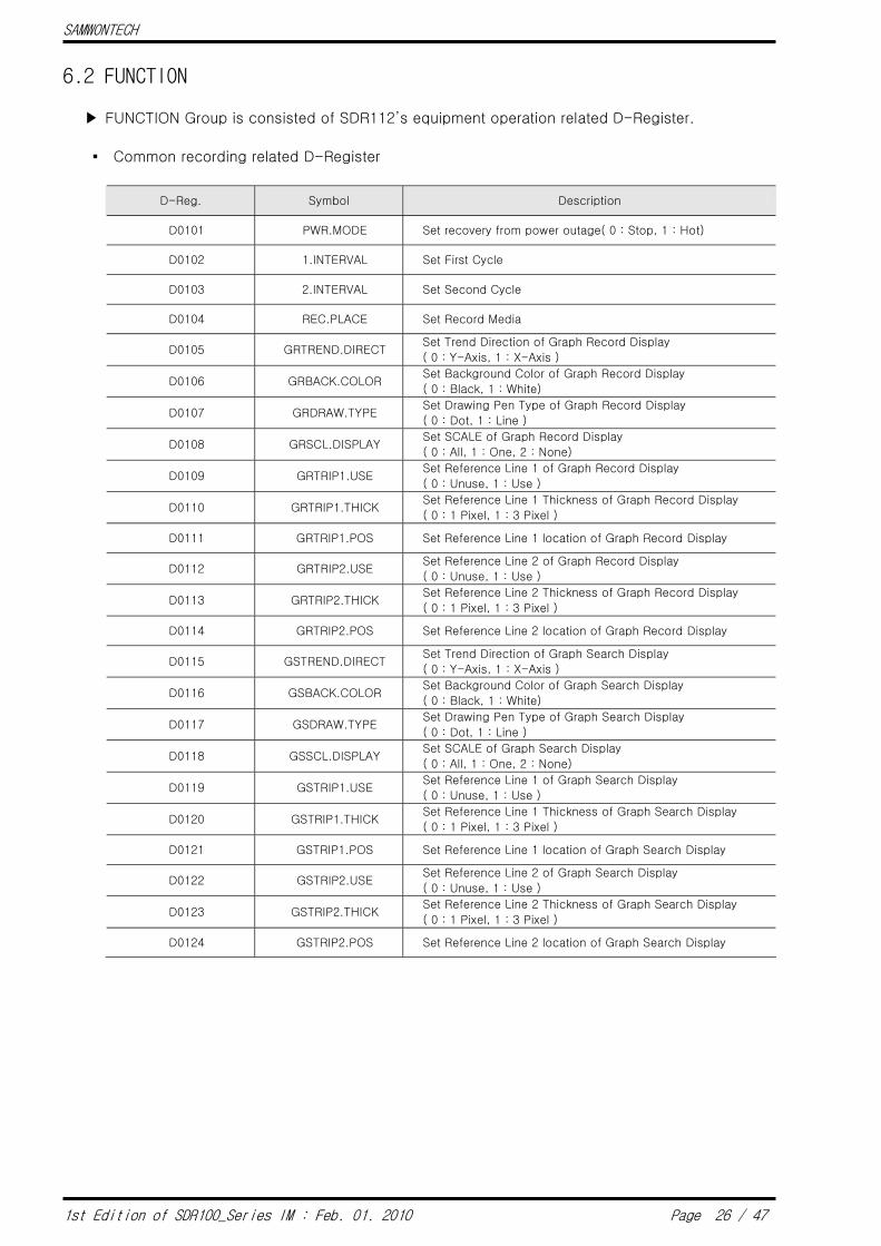
6.2 FUNCTION
▶ FUNCTION Group is consisted of SDR112’s equipment operation related D-Register.
▪ Common recording related D-Register
D-Reg. Symbol Description
D0101 PWR.MODE Set recovery from power outage( 0 : Stop, 1 : Hot)
D0102 1.INTERVAL Set First Cycle
D0103 2.INTERVAL Set Second Cycle
D0104 REC.PLACE Set Record Media
D0105 GRTREND.DIRECT Set Trend Direction of Graph Record Display
( 0 : Y-Axis, 1 : X-Axis )
D0106 GRBACK.COLOR Set Background Color of Graph Record Display
( 0 : Black, 1 : White)
D0107 GRDRAW.TYPE Set Drawing Pen Type of Graph Record Display
( 0 : Dot, 1 : Line )
D0108 GRSCL.DISPLAY Set SCALE of Graph Record Display
( 0 : All, 1 : One, 2 : None)
D0109 GRTRIP1.USE Set Reference Line 1 of Graph Record Display
( 0 : Unuse, 1 : Use )
D0110 GRTRIP1.THICK Set Reference Line 1 Thickness of Graph Record Display
( 0 : 1 Pixel, 1 : 3 Pixel )
D0111 GRTRIP1.POS Set Reference Line 1 location of Graph Record Display
D0112 GRTRIP2.USE Set Reference Line 2 of Graph Record Display
( 0 : Unuse, 1 : Use )
D0113 GRTRIP2.THICK Set Reference Line 2 Thickness of Graph Record Display
( 0 : 1 Pixel, 1 : 3 Pixel )
D0114 GRTRIP2.POS Set Reference Line 2 location of Graph Record Display
D0115 GSTREND.DIRECT Set Trend Direction of Graph Search Display
( 0 : Y-Axis, 1 : X-Axis )
D0116 GSBACK.COLOR Set Background Color of Graph Search Display
( 0 : Black, 1 : White)
D0117 GSDRAW.TYPE Set Drawing Pen Type of Graph Search Display
( 0 : Dot, 1 : Line )
D0118 GSSCL.DISPLAY Set SCALE of Graph Search Display
( 0 : All, 1 : One, 2 : None)
D0119 GSTRIP1.USE Set Reference Line 1 of Graph Search Display
( 0 : Unuse, 1 : Use )
D0120 GSTRIP1.THICK Set Reference Line 1 Thickness of Graph Search Display
( 0 : 1 Pixel, 1 : 3 Pixel )
D0121 GSTRIP1.POS Set Reference Line 1 location of Graph Search Display
D0122 GSTRIP2.USE Set Reference Line 2 of Graph Search Display
( 0 : Unuse, 1 : Use )
D0123 GSTRIP2.THICK Set Reference Line 2 Thickness of Graph Search Display
( 0 : 1 Pixel, 1 : 3 Pixel )
D0124 GSTRIP2.POS Set Reference Line 2 location of Graph Search Display
SAMWONTECH
1st Edition of SDR100_Series IM : Feb. 01. 2010 Page 27 / 47
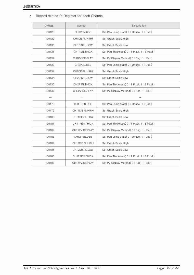
▪ Record related D-Register for each Channel
D-Reg. Symbol Description
D0128 CH1PEN.USE Set Pen using state( 0 : Unuse, 1 : Use )
D0129 CH1DISPL.HIRH Set Graph Scale High
D0130 CH1DISPL.LOW Set Graph Scale Low
D0131 CH1PEN.THICK Set Pen Thickness( 0 : 1 Pixel, 1 : 3 Pixel )
D0132 CH1PV.DISPLAY Set PV Display Method( 0 : Tag, 1 : Bar )
D0133 CH2PEN.USE Set Pen using state( 0 : Unuse, 1 : Use )
D0134 CH2DISPL.HIRH Set Graph Scale High
D0135 CH2DISPL.LOW Set Graph Scale Low
D0136 CH2PEN.THICK Set Pen Thickness( 0 : 1 Pixel, 1 : 3 Pixel )
D0137 CH2PV.DISPLAY Set PV Display Method( 0 : Tag, 1 : Bar )
… … …
D0178 CH11PEN.USE Set Pen using state( 0 : Unuse, 1 : Use )
D0179 CH11DISPL.HIRH Set Graph Scale High
D0180 CH11DISPL.LOW Set Graph Scale Low
D0181 CH11PEN.THICK Set Pen Thickness( 0 : 1 Pixel, 1 : 3 Pixel )
D0182 CH11PV.DISPLAY Set PV Display Method( 0 : Tag, 1 : Bar )
D0183 CH12PEN.USE Set Pen using state( 0 : Unuse, 1 : Use )
D0184 CH12DISPL.HIRH Set Graph Scale High
D0185 CH12DISPL.LOW Set Graph Scale Low
D0186 CH12PEN.THICK Set Pen Thickness( 0 : 1 Pixel, 1 : 3 Pixel )
D0187 CH12PV.DISPLAY Set PV Display Method( 0 : Tag, 1 : Bar )

SAMWONTECH
1st Edition of SDR100_Series IM : Feb. 01. 2010 Page 28 / 47
6.3 RESERVATION
▶ RESERVATION Group is consisted of SDR112’s Current Time Set and Reserve related
D-Register.
▪ Time related D-Register
D-Reg. Symbol Description Read Write
D0335 NOW.YEAR SDR112’s Current Time (YEAR) O X
D0336 NOW.MONTH SDR112’s Current Time (MONTH) O X
D0337 NOW.DAY SDR112’s Current Time (DAY) O X
D0338 NOW.AMPM SDR112’s Current Time (AM/PM) O X
D0339 NOW.HOUR SDR112’s Current Time (HOUR) O X
D0340 NOW.MIN SDR112’s Current Time (MIN) O X
D0341 C.YEAR Set SDR112’s Current Time (YEAR) X O
D0342 C.MONTH Set SDR112’s Current Time (MONTH) X O
D0343 C.DAY Set SDR112’s Current Time (DAY) X O
D0344 C.AMPM Set SDR112’s Current Time (AM/PM) X O
D0345 C.HOUR Set SDR112’s Current Time (HOUR) X O
D0346 C.MIN Set SDR112’s Current Time (MIN) X O
D0347 RES.S_YEAR Set Reserve Start Time (YEAR) O O
D0348 RES.S_MONTH Set Reserve Start Time (MONTH) O O
D0349 RES.S_DAY Set Reserve Start Time (DAY) O O
D0350 RES.S_AMPM Set Reserve Start Time (AM/PM) O O
D0351 RES.S_HOUR Set Reserve Start Time (HOUR) O O
D0352 RES.S_MIN Set Reserve Start Time (MIN) O O
D0353 RES.E_YEAR Set Reserve End Time (YEAR) O O
D0354 RES.E_MONTH Set Reserve End Time (MONTH) O O
D0355 RES.E_DAY Set Reserve End Time (DAY) O O
D0356 RES.E_AMPM Set Reserve End Time (AM/PM) O O
D0357 RES.E_HOUR Set Reserve End Time (HOUR) O O
D0358 RES.E_MIN Set Reserve End Time (MIN) O O
▪ Reserve Operation On/Off
D-Reg. Symbol Parameter Value Description
OFF 0 Release Reserve D0334 RESERVE.MMODE
ON 1 Set Reserve
SAMWONTECH
1st Edition of SDR100_Series IM : Feb. 01. 2010 Page 29 / 47
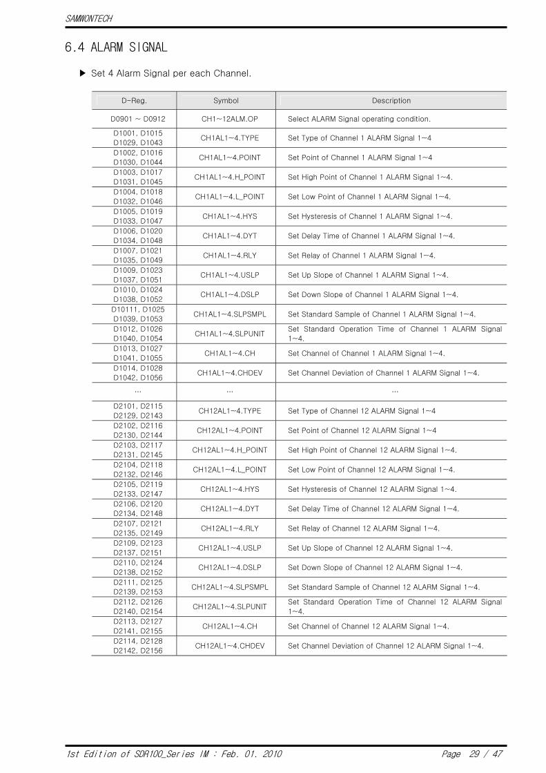
6.4 ALARM SIGNAL
▶ Set 4 Alarm Signal per each Channel.
D-Reg. Symbol Description
D0901 ~ D0912 CH1~12ALM.OP Select ALARM Signal operating condition.
D1001, D1015
D1029, D1043 CH1AL1~4.TYPE Set Type of Channel 1 ALARM Signal 1~4
D1002, D1016
D1030, D1044 CH1AL1~4.POINT Set Point of Channel 1 ALARM Signal 1~4
D1003, D1017
D1031, D1045 CH1AL1~4.H_POINT Set High Point of Channel 1 ALARM Signal 1~4.
D1004, D1018
D1032, D1046 CH1AL1~4.L_POINT Set Low Point of Channel 1 ALARM Signal 1~4.
D1005, D1019
D1033, D1047 CH1AL1~4.HYS Set Hysteresis of Channel 1 ALARM Signal 1~4.
D1006, D1020
D1034, D1048 CH1AL1~4.DYT Set Delay Time of Channel 1 ALARM Signal 1~4.
D1007, D1021
D1035, D1049 CH1AL1~4.RLY Set Relay of Channel 1 ALARM Signal 1~4.
D1009, D1023
D1037, D1051 CH1AL1~4.USLP Set Up Slope of Channel 1 ALARM Signal 1~4.
D1010, D1024
D1038, D1052 CH1AL1~4.DSLP Set Down Slope of Channel 1 ALARM Signal 1~4.
D10111, D1025
D1039, D1053 CH1AL1~4.SLPSMPL Set Standard Sample of Channel 1 ALARM Signal 1~4.
D1012, D1026
D1040, D1054 CH1AL1~4.SLPUNIT
Set Standard Operation Time of Channel 1 ALARM Signal
1~4.
D1013, D1027
D1041, D1055 CH1AL1~4.CH Set Channel of Channel 1 ALARM Signal 1~4.
D1014, D1028
D1042, D1056 CH1AL1~4.CHDEV Set Channel Deviation of Channel 1 ALARM Signal 1~4.
… … …
D2101, D2115
D2129, D2143 CH12AL1~4.TYPE Set Type of Channel 12 ALARM Signal 1~4
D2102, D2116
D2130, D2144 CH12AL1~4.POINT Set Point of Channel 12 ALARM Signal 1~4
D2103, D2117
D2131, D2145 CH12AL1~4.H_POINT Set High Point of Channel 12 ALARM Signal 1~4.
D2104, D2118
D2132, D2146 CH12AL1~4.L_POINT Set Low Point of Channel 12 ALARM Signal 1~4.
D2105, D2119
D2133, D2147 CH12AL1~4.HYS Set Hysteresis of Channel 12 ALARM Signal 1~4.
D2106, D2120
D2134, D2148 CH12AL1~4.DYT Set Delay Time of Channel 12 ALARM Signal 1~4.
D2107, D2121
D2135, D2149 CH12AL1~4.RLY Set Relay of Channel 12 ALARM Signal 1~4.
D2109, D2123
D2137, D2151 CH12AL1~4.USLP Set Up Slope of Channel 12 ALARM Signal 1~4.
D2110, D2124
D2138, D2152 CH12AL1~4.DSLP Set Down Slope of Channel 12 ALARM Signal 1~4.
D2111, D2125
D2139, D2153 CH12AL1~4.SLPSMPL Set Standard Sample of Channel 12 ALARM Signal 1~4.
D2112, D2126
D2140, D2154 CH12AL1~4.SLPUNIT
Set Standard Operation Time of Channel 12 ALARM Signal
1~4.
D2113, D2127
D2141, D2155 CH12AL1~4.CH Set Channel of Channel 12 ALARM Signal 1~4.
D2114, D2128
D2142, D2156 CH12AL1~4.CHDEV Set Channel Deviation of Channel 12 ALARM Signal 1~4.

SAMWONTECH
1st Edition of SDR100_Series IM : Feb. 01. 2010 Page 30 / 47
6.5 COMMUNICATION
▶ Check communication related setup information.
D-Reg. Symbol Description
D2301 PROTOCOL Able to check Communication Protocol.
D2302 BPS Able to check Baud Rate.
D2303 PARITY Able to check Parity.
D2304 STOP_BIT Able to check Stop Bit.
D2305 DATA_LENGTH Able to check Data Length.
D2306 ADDRESS Able to check Address.
D2307 RESPONSE Able to check Response Time.
SAMWONTECH
1st Edition of SDR100_Series IM : Feb. 01. 2010 Page 31 / 47
6.6 INPUT
▶ Set input items.
D-Reg. Symbol Description
D0401 CH1.SENGP Set Input Sensor Group of Channel 1.
D0402 CH1.SENTP Set Input Sensor Type of Channel 1.
D0403 CH1.UNIT Set Display Unit of Channel 1.
D0404 CH1.DP Set Dot Position of Channel 1.
D0405 CH1.TCSEL Set T/C Select of Channel 1.
D0406 CH1.INRH Set Range High of Channel 1.
D0407 CH1.INRL Set Range Low of Channel 1.
D0408 CH1.INSH Set Scale High of Channel 1.
D0409 CH1.INSL Set Scale Low of Channel 1.
D0410 ~ D0413 CH1.TAGNAME Set Tag Name of Channel 1.
D0414 CH1.SOPNSEL Set PV when Sensor Open at Channel 1.
D0415 CH1.MES Set Measure Method of Channel 1.
D0416 CH1.MESTM Set Measure Time for the Measure Method at Channel 1.
… … …
D0481 CH6.SENGP Set Input Sensor Group of Channel 6.
D0482 CH6.SENTP Set Input Sensor Type of Channel 6.
D0483 CH6.UNIT Set Display Unit of Channel 6.
D0484 CH6.DP Set Dot Position of Channel 6.
D0485 CH6.TCSEL Set T/C Select of Channel 6.
D0486 CH6.INRH Set Range High of Channel6.
D0487 CH6.INRL Set Range Low of Channel 6.
D0488 CH6.INSH Set Scale High of Channel 6.
D0489 CH6.INSL Set Scale Low of Channel 6.
D0490 ~ D0493 CH6.TAGNAME Set Tag Name of Channel 6.
D0494 CH6.SOPNSEL Set PV when Sensor Open at Channel 6.
D0495 CH6.MES Set Measure Method of Channel 6.
D0496 CH6.MESTM Set Measure Time for the Measure Method at Channel 6.

SAMWONTECH
1st Edition of SDR100_Series IM : Feb. 01. 2010 Page 32 / 47
D-Reg. Symbol Description
D0501 CH7.SENGP Set Input Sensor Group of Channel 7.
D0502 CH7.SENTP Set Input Sensor Type of Channel 7.
D0503 CH7.UNIT Set Display Unit of Channel 7.
D0504 CH7.DP Set Dot Position of Channel 7.
D0505 CH7.TCSEL Set T/C Select of Channel 7.
D0506 CH7.INRH Set Range High of Channel 7.
D0507 CH7.INRL Set Range Low of Channel 7.
D0508 CH7.INSH Set Scale High of Channel 7.
D0509 CH7.INSL Set Scale Low of Channel 7.
D0510 ~ D0513 CH7.TAGNAME Set Tag Name of Channel 7.
D0514 CH7.SOPNSEL Set PV when Sensor Open at Channel 7.
D0515 CH7.MES Set Measure Method of Channel 7.
D0516 CH7.MESTM Set Measure Time for the Measure Method at Channel 7.
… … …
D0581 CH12.SENGP Set Input Sensor Group of Channel 12.
D0582 CH12.SENTP Set Input Sensor Type of Channel 12.
D0583 CH12.UNIT Set Display Unit of Channel 12.
D0584 CH12.DP Set Dot Position of Channel 12.
D0585 CH12.TCSEL Set T/C Select of Channel 12.
D0586 CH12.INRH Set Range High of Channel 12.
D0587 CH12.INRL Set Range Low of Channel 12.
D0588 CH12.INSH Set Scale High of Channel 12.
D0589 CH12.INSL Set Scale Low of Channel 12.
D0590 ~ D0593 CH12.TAGNAME Set Tag Name of Channel 12.
D0594 CH12.SOPNSEL Set PV when Sensor Open at Channel 12.
D0595 CH12.MES Set Measure Method of Channel 12.
D0596 CH12.MESTM Set Measure Time for the Measure Method at Channel 12.

SAMWONTECH
1st Edition of SDR100_Series IM : Feb. 01. 2010 Page 33 / 47
6.7 DI CONFIG
▶ Set DI related items and Error Name.
D-Reg. Symbol Description
D2201 BUZ.TIME Set Buzzer Time when DI occurs.
D2202 DIDET.TIME Work as DI mode after set time when DI is detected.
(DI Detection Time)
D2203 DI1.OPMODE Set Operation Mode when DI1 occurs.
D2204 DI2.OPMODE Set Operation Mode when DI2 occurs.
D2205 DI1.RLY Set Relay when DI1 occurs.
D2206 DI2.RLY Set Relay when DI2 occurs.
6.8 PICTURE
▶ Set Picture View Operation and Rotation Time.
D-Reg. Symbol Description
D2401 VIEW.ROTATE Select the use of Customer BMP file.
D2402 R.ST_TIME START TIME by no key input to activate User Screen Viewer.
D2403 R.INT_TIME Rotate stored Customer BMP after specified interval time.
6.9 INITIAL
▶ Set Initial Display related initial value.
D-Reg. Symbol Description
D2501 LANGUAGE Select Language.
D2502 DISP.MODE Select Display Mode of initial display screen.
D2506 ~ D2518 INFORM1.NAME1 ~
INFORM1.NAME13 Set Information 1 Name of initial display screen.
… … …
D2532 ~ D2544 INFORM3.NAME1 ~
INFORM3.NAME13 Set Information 3 Name of initial display screen.

SAMWONTECH
1st Edition of SDR100_Series IM : Feb. 01. 2010 Page 34 / 47
D-Register 0000 ~ 0599 : Read Only
PROCESS FUNCTION DISPLAY1 DISPLAY2 INPUT1 INPUT2 D-Reg.
0 100 200 300 400 500
0
1 CH1.NPV PWR.MODE CANMSG1.NAME1 CANMSG9.NAME1 CH1.SENGP CH7.SENGP
2 CH2.NPV 1.INTERVAL CANMSG1.NAME2 CANMSG9.NAME2 CH1.SENTP CH7.SENTP
3 CH3.NPV 2.INTERVAL CANMSG1.NAME3 CANMSG9.NAME3 CH1.UNIT CH7.UNIT
4 CH4.NPV REC.PLACE CANMSG1.NAME4 CANMSG9.NAME4 CH1.DP CH7.DP
5 CH5.NPV GRTREND.DIRECT CANMSG1.NAME5 CANMSG9.NAME5 CH1.TCSEL CH7.TCSEL
6 CH6.NPV GRBACK.COLOR CANMSG1.NAME6 CANMSG9.NAME6 CH1.INRH CH7.INRH
7 CH7.NPV GRDRAW.TYPE CANMSG1.NAME7 CANMSG9.NAME7 CH1.INRL CH7.INRL
8 CH8.NPV GRSCL.DISPLAY CANMSG1.NAME8 CANMSG9.NAME8 CH1.INSH CH7.INSH
9 CH9.NPV GRTRIP1.USE CANMSG1.NAME9 CANMSG9.NAME9 CH1.INSH CH7.INSH
10 CH10.NPV GRTRIP1.THICK CANMSG1.NAME10 CANMSG9.NAME10 CH1.TAGNAME1 CH7.TAGNAME1
11 CH11.NPV GRTRP1.POS CANMSG1.NAME11 CANMSG9.NAME11 CH1.TAGNAME2 CH7.TAGNAME2
12 CH12.NPV GRTRIP2.USE CANMSG1.NAME12 CANMSG9.NAME12 CH1.TAGNAME3 CH7.TAGNAME3
13 GRTRIP2.THICK CANMSG2.NAME1 CANMSG10.NAME1 CH1.TAGNAME4 CH7.TAGNAME4
14 GRTRP2.POS CANMSG2.NAME2 CANMSG10.NAME2 CH1.SOPNSEL CH7.SOPNSEL
15 GSTREND.DIRECT CANMSG2.NAME3 CANMSG10.NAME3 CH1.MES CH7.MES
16 NOW.STATUS GSBACK.COLOR CANMSG2.NAME4 CANMSG10.NAME4 CH1.MESTM CH7.MESTM
17 GSDRAW.TYPE CANMSG2.NAME5 CANMSG10.NAME5 CH2.SENGP CH8.SENGP
18 GSSCL.DISPLAY CANMSG2.NAME6 CANMSG10.NAME6 CH2.SENTP CH8.SENTP
19 GSTRIP1.USE CANMSG2.NAME7 CANMSG10.NAME7 CH2.UNIT CH8.UNIT
20 CH1ALM.STS GSTRIP1.THICK CANMSG2.NAME8 CANMSG10.NAME8 CH2.DP CH8.DP
21 CH2ALM.STS GSTRP1.POS CANMSG2.NAME9 CANMSG10.NAME9 CH2.TCSEL CH8.TCSEL
22 CH3ALM.STS GSTRIP2.USE CANMSG2.NAME10 CANMSG10.NAME10 CH2.INRH CH8.INRH
23 CH4ALM.STS GSTRIP2.THICK CANMSG2.NAME11 CANMSG10.NAME11 CH2.INRL CH8.INRL
24 CH5ALM.STS GSTRP2.POS CANMSG2.NAME12 CANMSG10.NAME12 CH2.INSH CH8.INSH
25 CH6ALM.STS CANMSG3.NAME1 CH2.INSH CH8.INSH
26 CH7ALM.STS CANMSG3.NAME2 CH2.TAGNAME1 CH8.TAGNAME1
27 CH8ALM.STS CANMSG3.NAME3 CH2.TAGNAME2 CH8.TAGNAME2
28 CH9ALM.STS CH1PEN.USE CANMSG3.NAME4 BUZ.ONOFF CH2.TAGNAME3 CH8.TAGNAME3
29 CH10ALM.STS CH1DISPL.HIGH CANMSG3.NAME5 LIGHT.OFFTM CH2.TAGNAME4 CH8.TAGNAME4
30 CH11ALM.STS CH1DISPL.LOW CANMSG3.NAME6 GRAPH.ROT_TIME CH2.SOPNSEL CH8.SOPNSEL
31 CH12ALM.STS CH1PEN.THICK CANMSG3.NAME7 CH2.MES CH8.MES
32 CH1PV.DISPLAY CANMSG3.NAME8 CH2.MESTM CH8.MESTM
33 CH2PEN.USE CANMSG3.NAME9 CH3.SENGP CH9.SENGP
34 CH2DISPL.HIGH CANMSG3.NAME10 RESERVE.MODE CH3.SENTP CH9.SENTP
35 CH1ADERR.STS CH2DISPL.LOW CANMSG3.NAME11 NOW.YEAR CH3.UNIT CH9.UNIT
36 CH2ADERR.STS CH2PEN.THICK CANMSG3.NAME12 NOW.MONTH CH3.DP CH9.DP
37 CH3ADERR.STS CH2PV.DISPLAY CANMSG4.NAME1 NOW.DAY CH3.TCSEL CH9.TCSEL
38 CH4ADERR.STS CH3PEN.USE CANMSG4.NAME2 NOW.AMPM CH3.INRH CH9.INRH
39 CH5ADERR.STS CH3DISPL.HIGH CANMSG4.NAME3 NOW.HOUR CH3.INRL CH9.INRL
40 CH6ADERR.STS CH3DISPL.LOW CANMSG4.NAME4 NOW.MIN CH3.INSH CH9.INSH
41 CH7ADERR.STS CH3PEN.THICK CANMSG4.NAME5 C.YEAR CH3.INSH CH9.INSH
42 CH8ADERR.STS CH3PV.DISPLAY CANMSG4.NAME6 C.MONTH CH3.TAGNAME1 CH9.TAGNAME1
43 CH9ADERR.STS CH4PEN.USE CANMSG4.NAME7 C.DAY CH3.TAGNAME2 CH9.TAGNAME2
44 CH10ADERR.STS CH4DISPL.HIGH CANMSG4.NAME8 C.AMPM CH3.TAGNAME3 CH9.TAGNAME3
45 CH11ADERR.STS CH4DISPL.LOW CANMSG4.NAME9 C.HOUR CH3.TAGNAME4 CH9.TAGNAME4
46 CH12ADERR.STS CH4PEN.THICK CANMSG4.NAME10 C.MIN CH3.SOPNSEL CH9.SOPNSEL
47 CH4PV.DISPLAY CANMSG4.NAME11 RES.S_YEAR CH3.MES CH9.MES
48 CH5PEN.USE CANMSG4.NAME12 RES.S_MONTH CH3.MESTM CH9.MESTM
49 CH5DISPL.HIGH CANMSG5.NAME1 RES.S_DAY CH4.SENGP CH10.SENGP

SAMWONTECH
1st Edition of SDR100_Series IM : Feb. 01. 2010 Page 35 / 47
PROCESS FUNCTION DISPLAY1 DISPLAY2 INPUT1 INPUT2 D-Reg.
0 100 200 300 400 500
50 D0_STATUS CH5DISPL.LOW CANMSG5.NAME2 RES.S_AMPM CH4.SENTP CH10.SENTP
51 DI_DATA CH5PEN.THICK CANMSG5.NAME3 RES.S_HOUR CH4.UNIT CH10.UNIT
52 CH5PV.DISPLAY CANMSG5.NAME4 RES.S_MIN CH4.DP CH10.DP
53 CH6PEN.USE CANMSG5.NAME5 RES.E_YEAR CH4.TCSEL CH10.TCSEL
54 CH6DISPL.HIGH CANMSG5.NAME6 RES.E_MONTH CH4.INRH CH10.INRH
55 CH6DISPL.LOW CANMSG5.NAME7 RES.E_DAY CH4.INRL CH10.INRL
56 CH6PEN.THICK CANMSG5.NAME8 RES.E_AMPM CH4.INSH CH10.INSH
57 CH6PV.DISPLAY CANMSG5.NAME9 RES.E_HOUR CH4.INSH CH10.INSH
58 CH7PEN.USE CANMSG5.NAME10 RES.E_MIN CH4.TAGNAME1 CH10.TAGNAME1
59 CH7DISPL.HIGH CANMSG5.NAME11 CH4.TAGNAME2 CH10.TAGNAME2
60 CH7DISPL.LOW CANMSG5.NAME12 CH4.TAGNAME3 CH10.TAGNAME3
61 CH7PEN.THICK CANMSG6.NAME1 CH4.TAGNAME4 CH10.TAGNAME4
62 CH7PV.DISPLAY CANMSG6.NAME2 CH4.SOPNSEL CH10.SOPNSEL
63 CH8PEN.USE CANMSG6.NAME3 CH4.MES CH10.MES
64 CH8DISPL.HIGH CANMSG6.NAME4 CH4.MESTM CH10.MESTM
65 CH8DISPL.LOW CANMSG6.NAME5 CH5.SENGP CH11.SENGP
66 CH8PEN.THICK CANMSG6.NAME6 CH5.SENTP CH11.SENTP
67 CH8PV.DISPLAY CANMSG6.NAME7 CH5.UNIT CH11.UNIT
68 CH9PEN.USE CANMSG6.NAME8 CH5.DP CH11.DP
69 CH9DISPL.HIGH CANMSG6.NAME9 CH5.TCSEL CH11.TCSEL
70 CH9DISPL.LOW CANMSG6.NAME10 CH5.INRH CH11.INRH
71 CH9PEN.THICK CANMSG6.NAME11 CH5.INRL CH11.INRL
72 CH9PV.DISPLAY CANMSG6.NAME12 CH5.INSH CH11.INSH
73 CH10PEN.USE CANMSG7.NAME1 CH5.INSH CH11.INSH
74 CH10DISPL.HIGH CANMSG7.NAME2 CH5.TAGNAME1 CH11.TAGNAME1
75 CH10DISPL.LOW CANMSG7.NAME3 CH5.TAGNAME2 CH11.TAGNAME2
76 CH10PEN.THICK CANMSG7.NAME4 CH5.TAGNAME3 CH11.TAGNAME3
77 CH10PV.DISPLAY CANMSG7.NAME5 CH5.TAGNAME4 CH11.TAGNAME4
78 CH11PEN.USE CANMSG7.NAME6 CH5.SOPNSEL CH11.SOPNSEL
79 CH11DISPL.HIGH CANMSG7.NAME7 CH5.MES CH11.MES
80 CH11DISPL.LOW CANMSG7.NAME8 CH5.MESTM CH11.MESTM
81 CH11PEN.THICK CANMSG7.NAME9 CH6.SENGP CH12.SENGP
82 CH11PV.DISPLAY CANMSG7.NAME10 CH6.SENTP CH12.SENTP
83 CH12PEN.USE CANMSG7.NAME11 CH6.UNIT CH12.UNIT
84 CH12DISPL.HIGH CANMSG7.NAME12 CH6.DP CH12.DP
85 CH12DISPL.LOW CANMSG8.NAME1 CH6.TCSEL CH12.TCSEL
86 CH12PEN.THICK CANMSG8.NAME2 CH6.INRH CH12.INRH
87 CH12PV.DISPLAY CANMSG8.NAME3 CH6.INRL CH12.INRL
88 CANMSG8.NAME4 CH6.INSH CH12.INSH
89 CANMSG8.NAME5 CH6.INSH CH12.INSH
90 CANMSG8.NAME6 CH6.TAGNAME1 CH12.TAGNAME1
91 CANMSG8.NAME7 CH6.TAGNAME2 CH12.TAGNAME2
92 CANMSG8.NAME8 CH6.TAGNAME3 CH12.TAGNAME3
93 CANMSG8.NAME9 CH6.TAGNAME4 CH12.TAGNAME4
94 CANMSG8.NAME10 CH6.SOPNSEL CH12.SOPNSEL
95 CANMSG8.NAME11 CH6.MES CH12.MES
96 CANMSG8.NAME12 CH6.MESTM CH12.MESTM
97
98
99

SAMWONTECH
1st Edition of SDR100_Series IM : Feb. 01. 2010 Page 36 / 47
D-Register 0600 ~ 1199
INPUT3 INPUT4 INPUT5 ALARM1 ALARM2 ALARM3 D-Reg.
600 700 800 900 1000 1100
0
1 CH1ALM.OP CH1AL1.TYPE CH2AL1.TYPE
2 CH2ALM.OP CH1AL1.POINT CH2AL1.POINT
3 CH3ALM.OP CH1AL1.H_POINT CH2AL1.H_POINT
4 CH4ALM.OP CH1AL1.L_POINT CH2AL1.L_POINT
5 CH5ALM.OP CH1AL1.HYS CH2AL1.HYS
6 CH6ALM.OP CH1AL1.DYT CH2AL1.DYT
7 CH7ALM.OP CH1AL1.RLY CH2AL1.RLY
8 CH8ALM.OP CH1AL1.ACT CH2AL1.ACT
9 CH9ALM.OP CH1AL1.USLP CH2AL1.USLP
10 CH10ALM.OP CH1AL1.DSLP CH2AL1.DSLP
11 CH11ALM.OP CH1AL1.SLPSMPL CH2AL1.SLPSMPL
12 CH12ALM.OP CH1AL1.SLPUNIT CH2AL1.SLPUNIT
13 CH1AL1.CH CH2AL1.CH
14 CH1AL1.CHDEV CH2AL1.CHDEV
15 CH1AL2.TYPE CH2AL2.TYPE
16 CH1AL2.POINT CH2AL2.POINT
17 CH1AL2.H_POINT CH2AL2.H_POINT
18 CH1AL2.L_POINT CH2AL2.L_POINT
19 CH1AL2.HYS CH2AL2.HYS
20 CH1AL2.DYT CH2AL2.DYT
21 CH1AL2.RLY CH2AL2.RLY
22 CH1AL2.ACT CH2AL2.ACT
23 CH1AL2.USLP CH2AL2.USLP
24 CH1AL2.DSLP CH2AL2.DSLP
25 CH1AL2.SLPSMPL CH2AL2.SLPSMPL
26 CH1AL2.SLPUNIT CH2AL2.SLPUNIT
27 CH1AL2.CH CH2AL2.CH
28 CH1AL2.CHDEV CH2AL2.CHDEV
29 CH1AL3.TYPE CH2AL3.TYPE
30 CH1AL3.POINT CH2AL3.POINT
31 CH1AL3.H_POINT CH2AL3.H_POINT
32 CH1AL3.L_POINT CH2AL3.L_POINT
33 CH1AL3.HYS CH2AL3.HYS
34 CH1AL3.DYT CH2AL3.DYT
35 CH1AL3.RLY CH2AL3.RLY
36 CH1AL3.ACT CH2AL3.ACT
37 CH1AL3.USLP CH2AL3.USLP
38 CH1AL3.DSLP CH2AL3.DSLP
39 CH1AL3.SLPSMPL CH2AL3.SLPSMPL
40 CH1AL3.SLPUNIT CH2AL3.SLPUNIT
41 CH1AL3.CH CH2AL3.CH
42 CH1AL3.CHDEV CH2AL3.CHDEV
43 CH1AL4.TYPE CH2AL4.TYPE
44 CH1AL4.POINT CH2AL4.POINT
45 CH1AL4.H_POINT CH2AL4.H_POINT
46 CH1AL4.L_POINT CH2AL4.L_POINT
47 CH1AL4.HYS CH2AL4.HYS
48 CH1AL4.DYT CH2AL4.DYT
49 CH1AL4.RLY CH2AL4.RLY
SAMWONTECH
1st Edition of SDR100_Series IM : Feb. 01. 2010 Page 37 / 47
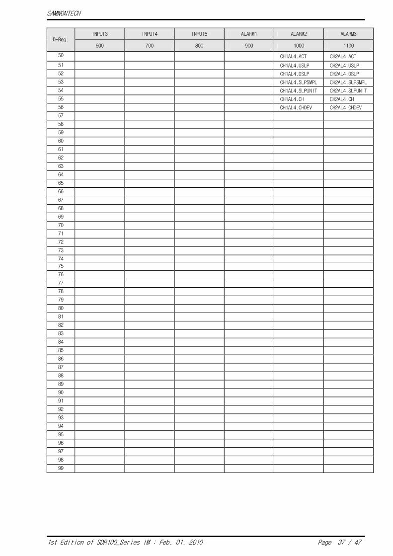
INPUT3 INPUT4 INPUT5 ALARM1 ALARM2 ALARM3 D-Reg.
600 700 800 900 1000 1100
50 CH1AL4.ACT CH2AL4.ACT
51 CH1AL4.USLP CH2AL4.USLP
52 CH1AL4.DSLP CH2AL4.DSLP
53 CH1AL4.SLPSMPL CH2AL4.SLPSMPL
54 CH1AL4.SLPUNIT CH2AL4.SLPUNIT
55 CH1AL4.CH CH2AL4.CH
56 CH1AL4.CHDEV CH2AL4.CHDEV
57
58
59
60
61
62
63
64
65
66
67
68
69
70
71
72
73
74
75
76
77
78
79
80
81
82
83
84
85
86
87
88
89
90
91
92
93
94
95
96
97
98
99
SAMWONTECH
1st Edition of SDR100_Series IM : Feb. 01. 2010 Page 38 / 47
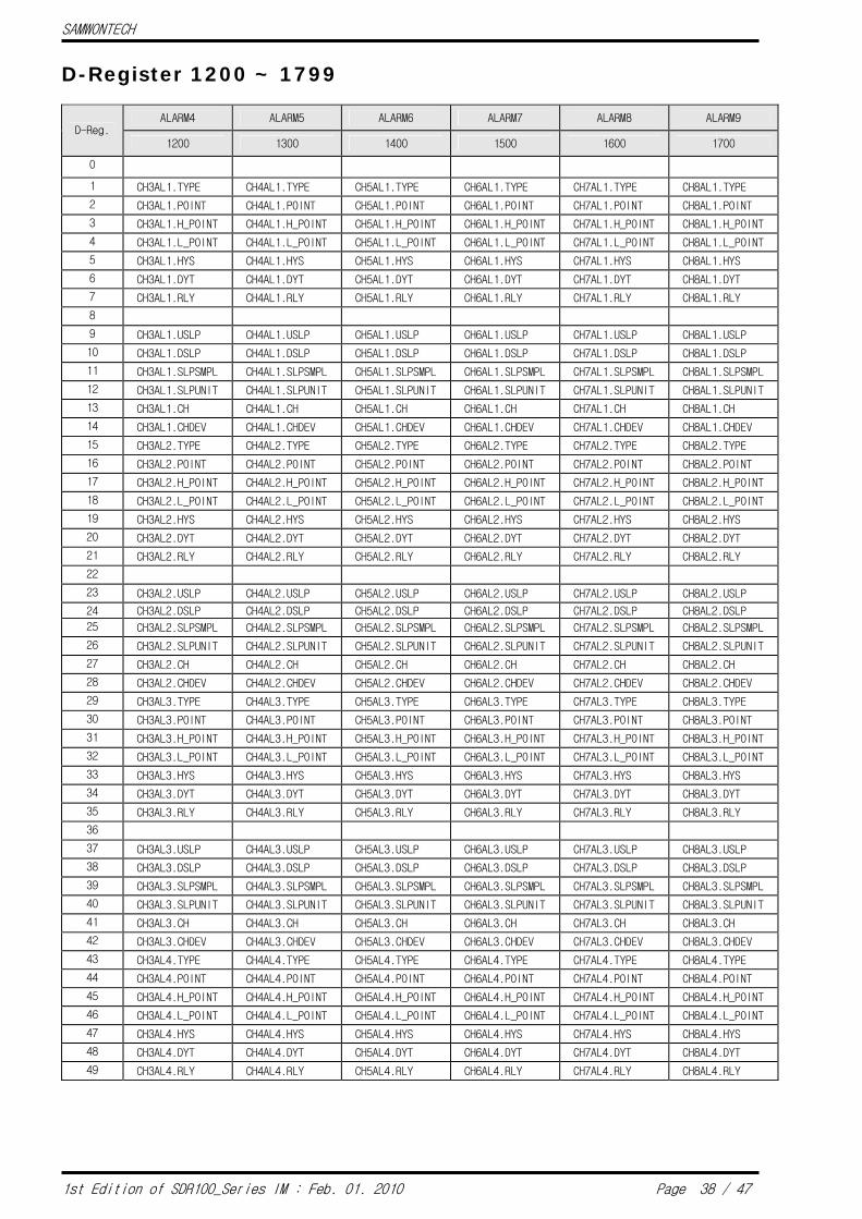
D-Register 1200 ~ 1799
ALARM4 ALARM5 ALARM6 ALARM7 ALARM8 ALARM9 D-Reg.
1200 1300 1400 1500 1600 1700
0
1 CH3AL1.TYPE CH4AL1.TYPE CH5AL1.TYPE CH6AL1.TYPE CH7AL1.TYPE CH8AL1.TYPE
2 CH3AL1.POINT CH4AL1.POINT CH5AL1.POINT CH6AL1.POINT CH7AL1.POINT CH8AL1.POINT
3 CH3AL1.H_POINT CH4AL1.H_POINT CH5AL1.H_POINT CH6AL1.H_POINT CH7AL1.H_POINT CH8AL1.H_POINT
4 CH3AL1.L_POINT CH4AL1.L_POINT CH5AL1.L_POINT CH6AL1.L_POINT CH7AL1.L_POINT CH8AL1.L_POINT
5 CH3AL1.HYS CH4AL1.HYS CH5AL1.HYS CH6AL1.HYS CH7AL1.HYS CH8AL1.HYS
6 CH3AL1.DYT CH4AL1.DYT CH5AL1.DYT CH6AL1.DYT CH7AL1.DYT CH8AL1.DYT
7 CH3AL1.RLY CH4AL1.RLY CH5AL1.RLY CH6AL1.RLY CH7AL1.RLY CH8AL1.RLY
8
9 CH3AL1.USLP CH4AL1.USLP CH5AL1.USLP CH6AL1.USLP CH7AL1.USLP CH8AL1.USLP
10 CH3AL1.DSLP CH4AL1.DSLP CH5AL1.DSLP CH6AL1.DSLP CH7AL1.DSLP CH8AL1.DSLP
11 CH3AL1.SLPSMPL CH4AL1.SLPSMPL CH5AL1.SLPSMPL CH6AL1.SLPSMPL CH7AL1.SLPSMPL CH8AL1.SLPSMPL
12 CH3AL1.SLPUNIT CH4AL1.SLPUNIT CH5AL1.SLPUNIT CH6AL1.SLPUNIT CH7AL1.SLPUNIT CH8AL1.SLPUNIT
13 CH3AL1.CH CH4AL1.CH CH5AL1.CH CH6AL1.CH CH7AL1.CH CH8AL1.CH
14 CH3AL1.CHDEV CH4AL1.CHDEV CH5AL1.CHDEV CH6AL1.CHDEV CH7AL1.CHDEV CH8AL1.CHDEV
15 CH3AL2.TYPE CH4AL2.TYPE CH5AL2.TYPE CH6AL2.TYPE CH7AL2.TYPE CH8AL2.TYPE
16 CH3AL2.POINT CH4AL2.POINT CH5AL2.POINT CH6AL2.POINT CH7AL2.POINT CH8AL2.POINT
17 CH3AL2.H_POINT CH4AL2.H_POINT CH5AL2.H_POINT CH6AL2.H_POINT CH7AL2.H_POINT CH8AL2.H_POINT
18 CH3AL2.L_POINT CH4AL2.L_POINT CH5AL2.L_POINT CH6AL2.L_POINT CH7AL2.L_POINT CH8AL2.L_POINT
19 CH3AL2.HYS CH4AL2.HYS CH5AL2.HYS CH6AL2.HYS CH7AL2.HYS CH8AL2.HYS
20 CH3AL2.DYT CH4AL2.DYT CH5AL2.DYT CH6AL2.DYT CH7AL2.DYT CH8AL2.DYT
21 CH3AL2.RLY CH4AL2.RLY CH5AL2.RLY CH6AL2.RLY CH7AL2.RLY CH8AL2.RLY
22
23 CH3AL2.USLP CH4AL2.USLP CH5AL2.USLP CH6AL2.USLP CH7AL2.USLP CH8AL2.USLP
24 CH3AL2.DSLP CH4AL2.DSLP CH5AL2.DSLP CH6AL2.DSLP CH7AL2.DSLP CH8AL2.DSLP
25 CH3AL2.SLPSMPL CH4AL2.SLPSMPL CH5AL2.SLPSMPL CH6AL2.SLPSMPL CH7AL2.SLPSMPL CH8AL2.SLPSMPL
26 CH3AL2.SLPUNIT CH4AL2.SLPUNIT CH5AL2.SLPUNIT CH6AL2.SLPUNIT CH7AL2.SLPUNIT CH8AL2.SLPUNIT
27 CH3AL2.CH CH4AL2.CH CH5AL2.CH CH6AL2.CH CH7AL2.CH CH8AL2.CH
28 CH3AL2.CHDEV CH4AL2.CHDEV CH5AL2.CHDEV CH6AL2.CHDEV CH7AL2.CHDEV CH8AL2.CHDEV
29 CH3AL3.TYPE CH4AL3.TYPE CH5AL3.TYPE CH6AL3.TYPE CH7AL3.TYPE CH8AL3.TYPE
30 CH3AL3.POINT CH4AL3.POINT CH5AL3.POINT CH6AL3.POINT CH7AL3.POINT CH8AL3.POINT
31 CH3AL3.H_POINT CH4AL3.H_POINT CH5AL3.H_POINT CH6AL3.H_POINT CH7AL3.H_POINT CH8AL3.H_POINT
32 CH3AL3.L_POINT CH4AL3.L_POINT CH5AL3.L_POINT CH6AL3.L_POINT CH7AL3.L_POINT CH8AL3.L_POINT
33 CH3AL3.HYS CH4AL3.HYS CH5AL3.HYS CH6AL3.HYS CH7AL3.HYS CH8AL3.HYS
34 CH3AL3.DYT CH4AL3.DYT CH5AL3.DYT CH6AL3.DYT CH7AL3.DYT CH8AL3.DYT
35 CH3AL3.RLY CH4AL3.RLY CH5AL3.RLY CH6AL3.RLY CH7AL3.RLY CH8AL3.RLY
36
37 CH3AL3.USLP CH4AL3.USLP CH5AL3.USLP CH6AL3.USLP CH7AL3.USLP CH8AL3.USLP
38 CH3AL3.DSLP CH4AL3.DSLP CH5AL3.DSLP CH6AL3.DSLP CH7AL3.DSLP CH8AL3.DSLP
39 CH3AL3.SLPSMPL CH4AL3.SLPSMPL CH5AL3.SLPSMPL CH6AL3.SLPSMPL CH7AL3.SLPSMPL CH8AL3.SLPSMPL
40 CH3AL3.SLPUNIT CH4AL3.SLPUNIT CH5AL3.SLPUNIT CH6AL3.SLPUNIT CH7AL3.SLPUNIT CH8AL3.SLPUNIT
41 CH3AL3.CH CH4AL3.CH CH5AL3.CH CH6AL3.CH CH7AL3.CH CH8AL3.CH
42 CH3AL3.CHDEV CH4AL3.CHDEV CH5AL3.CHDEV CH6AL3.CHDEV CH7AL3.CHDEV CH8AL3.CHDEV
43 CH3AL4.TYPE CH4AL4.TYPE CH5AL4.TYPE CH6AL4.TYPE CH7AL4.TYPE CH8AL4.TYPE
44 CH3AL4.POINT CH4AL4.POINT CH5AL4.POINT CH6AL4.POINT CH7AL4.POINT CH8AL4.POINT
45 CH3AL4.H_POINT CH4AL4.H_POINT CH5AL4.H_POINT CH6AL4.H_POINT CH7AL4.H_POINT CH8AL4.H_POINT
46 CH3AL4.L_POINT CH4AL4.L_POINT CH5AL4.L_POINT CH6AL4.L_POINT CH7AL4.L_POINT CH8AL4.L_POINT
47 CH3AL4.HYS CH4AL4.HYS CH5AL4.HYS CH6AL4.HYS CH7AL4.HYS CH8AL4.HYS
48 CH3AL4.DYT CH4AL4.DYT CH5AL4.DYT CH6AL4.DYT CH7AL4.DYT CH8AL4.DYT
49 CH3AL4.RLY CH4AL4.RLY CH5AL4.RLY CH6AL4.RLY CH7AL4.RLY CH8AL4.RLY

SAMWONTECH
1st Edition of SDR100_Series IM : Feb. 01. 2010 Page 39 / 47
ALARM4 ALARM5 ALARM6 ALARM7 ALARM8 ALARM9 D-Reg.
1200 1300 1400 1500 1600 1700
50
51 CH3AL4.USLP CH4AL4.USLP CH5AL4.USLP CH6AL4.USLP CH7AL4.USLP CH8AL4.USLP
52 CH3AL4.DSLP CH4AL4.DSLP CH5AL4.DSLP CH6AL4.DSLP CH7AL4.DSLP CH8AL4.DSLP
53 CH3AL4.SLPSMPL CH4AL4.SLPSMPL CH5AL4.SLPSMPL CH6AL4.SLPSMPL CH7AL4.SLPSMPL CH8AL4.SLPSMPL
54 CH3AL4.SLPUNIT CH4AL4.SLPUNIT CH5AL4.SLPUNIT CH6AL4.SLPUNIT CH7AL4.SLPUNIT CH8AL4.SLPUNIT
55 CH3AL4.CH CH4AL4.CH CH5AL4.CH CH6AL4.CH CH7AL4.CH CH8AL4.CH
56 CH3AL4.CHDEV CH4AL4.CHDEV CH5AL4.CHDEV CH6AL4.CHDEV CH7AL4.CHDEV CH8AL4.CHDEV
57
58
59
60
61
62
63
64
65
66
67
68
69
70
71
72
73
74
75
76
77
78
79
80
81
82
83
84
85
86
87
88
89
90
91
92
93
94
95
96
97
98
99

SAMWONTECH
1st Edition of SDR100_Series IM : Feb. 01. 2010 Page 40 / 47
D-Register 1800 ~ 2399
ALARM10 ALARM11 ALARM12 ALARM13 DICONFIG COMMUNICATION D-Reg.
1800 1900 2000 2100 2200 2300
0
1 CH9AL1.TYPE CH10AL1.TYPE CH11AL1.TYPE CH12AL1.TYPE BUZ.TIME PROTOCOL
2 CH9AL1.POINT CH10AL1.POINT CH11AL1.POINT CH12AL1.POINT DIDET.TIME BPS
3 CH9AL1.H_POINT CH10AL1.H_POINT CH11AL1.H_POINT CH12AL1.H_POINT DI1.OPMODE PARITY
4 CH9AL1.L_POINT CH10AL1.L_POINT CH11AL1.L_POINT CH12AL1.L_POINT DI2.OPMODE STOP_BIT
5 CH9AL1.HYS CH10AL1.HYS CH11AL1.HYS CH12AL1.HYS DI1.RLY DATA_LENGTH
6 CH9AL1.DYT CH10AL1.DYT CH11AL1.DYT CH12AL1.DYT DI2.RLY ADDRESS
7 CH9AL1.RLY CH10AL1.RLY CH11AL1.RLY CH12AL1.RLY RESPONSE
8
9 CH9AL1.USLP CH10AL1.USLP CH11AL1.USLP CH12AL1.USLP
10 CH9AL1.DSLP CH10AL1.DSLP CH11AL1.DSLP CH12AL1.DSLP
11 CH9AL1.SLPSMPL CH10AL1.SLPSMPL CH11AL1.SLPSMPL CH12AL1.SLPSMPL
12 CH9AL1.SLPUNIT CH10AL1.SLPUNIT CH11AL1.SLPUNIT CH12AL1.SLPUNIT
13 CH9AL1.CH CH10AL1.CH CH11AL1.CH CH12AL1.CH
14 CH9AL1.CHDEV CH10AL1.CHDEV CH11AL1.CHDEV CH12AL1.CHDEV
15 CH9AL2.TYPE CH10AL2.TYPE CH11AL2.TYPE CH12AL2.TYPE
16 CH9AL2.POINT CH10AL2.POINT CH11AL2.POINT CH12AL2.POINT
17 CH9AL2.H_POINT CH10AL2.H_POINT CH11AL2.H_POINT CH12AL2.H_POINT
18 CH9AL2.L_POINT CH10AL2.L_POINT CH11AL2.L_POINT CH12AL2.L_POINT
19 CH9AL2.HYS CH10AL2.HYS CH11AL2.HYS CH12AL2.HYS
20 CH9AL2.DYT CH10AL2.DYT CH11AL2.DYT CH12AL2.DYT
21 CH9AL2.RLY CH10AL2.RLY CH11AL2.RLY CH12AL2.RLY
22
23 CH9AL2.USLP CH10AL2.USLP CH11AL2.USLP CH12AL2.USLP
24 CH9AL2.DSLP CH10AL2.DSLP CH11AL2.DSLP CH12AL2.DSLP
25 CH9AL2.SLPSMPL CH10AL2.SLPSMPL CH11AL2.SLPSMPL CH12AL2.SLPSMPL
26 CH9AL2.SLPUNIT CH10AL2.SLPUNIT CH11AL2.SLPUNIT CH12AL2.SLPUNIT
27 CH9AL2.CH CH10AL2.CH CH11AL2.CH CH12AL2.CH
28 CH9AL2.CHDEV CH10AL2.CHDEV CH11AL2.CHDEV CH12AL2.CHDEV
29 CH9AL3.TYPE CH10AL3.TYPE CH11AL3.TYPE CH12AL3.TYPE
30 CH9AL3.POINT CH10AL3.POINT CH11AL3.POINT CH12AL3.POINT
31 CH9AL3.H_POINT CH10AL3.H_POINT CH11AL3.H_POINT CH12AL3.H_POINT
32 CH9AL3.L_POINT CH10AL3.L_POINT CH11AL3.L_POINT CH12AL3.L_POINT
33 CH9AL3.HYS CH10AL3.HYS CH11AL3.HYS CH12AL3.HYS
34 CH9AL3.DYT CH10AL3.DYT CH11AL3.DYT CH12AL3.DYT
35 CH9AL3.RLY CH10AL3.RLY CH11AL3.RLY CH12AL3.RLY
36
37 CH9AL3.USLP CH10AL3.USLP CH11AL3.USLP CH12AL3.USLP
38 CH9AL3.DSLP CH10AL3.DSLP CH11AL3.DSLP CH12AL3.DSLP
39 CH9AL3.SLPSMPL CH10AL3.SLPSMPL CH11AL3.SLPSMPL CH12AL3.SLPSMPL
40 CH9AL3.SLPUNIT CH10AL3.SLPUNIT CH11AL3.SLPUNIT CH12AL3.SLPUNIT
41 CH9AL3.CH CH10AL3.CH CH11AL3.CH CH12AL3.CH
42 CH9AL3.CHDEV CH10AL3.CHDEV CH11AL3.CHDEV CH12AL3.CHDEV
43 CH9AL4.TYPE CH10AL4.TYPE CH11AL4.TYPE CH12AL4.TYPE
44 CH9AL4.POINT CH10AL4.POINT CH11AL4.POINT CH12AL4.POINT
45 CH9AL4.H_POINT CH10AL4.H_POINT CH11AL4.H_POINT CH12AL4.H_POINT
46 CH9AL4.L_POINT CH10AL4.L_POINT CH11AL4.L_POINT CH12AL4.L_POINT
47 CH9AL4.HYS CH10AL4.HYS CH11AL4.HYS CH12AL4.HYS
48 CH9AL4.DYT CH10AL4.DYT CH11AL4.DYT CH12AL4.DYT
49 CH9AL4.RLY CH10AL4.RLY CH11AL4.RLY CH12AL4.RLY
SAMWONTECH
1st Edition of SDR100_Series IM : Feb. 01. 2010 Page 41 / 47
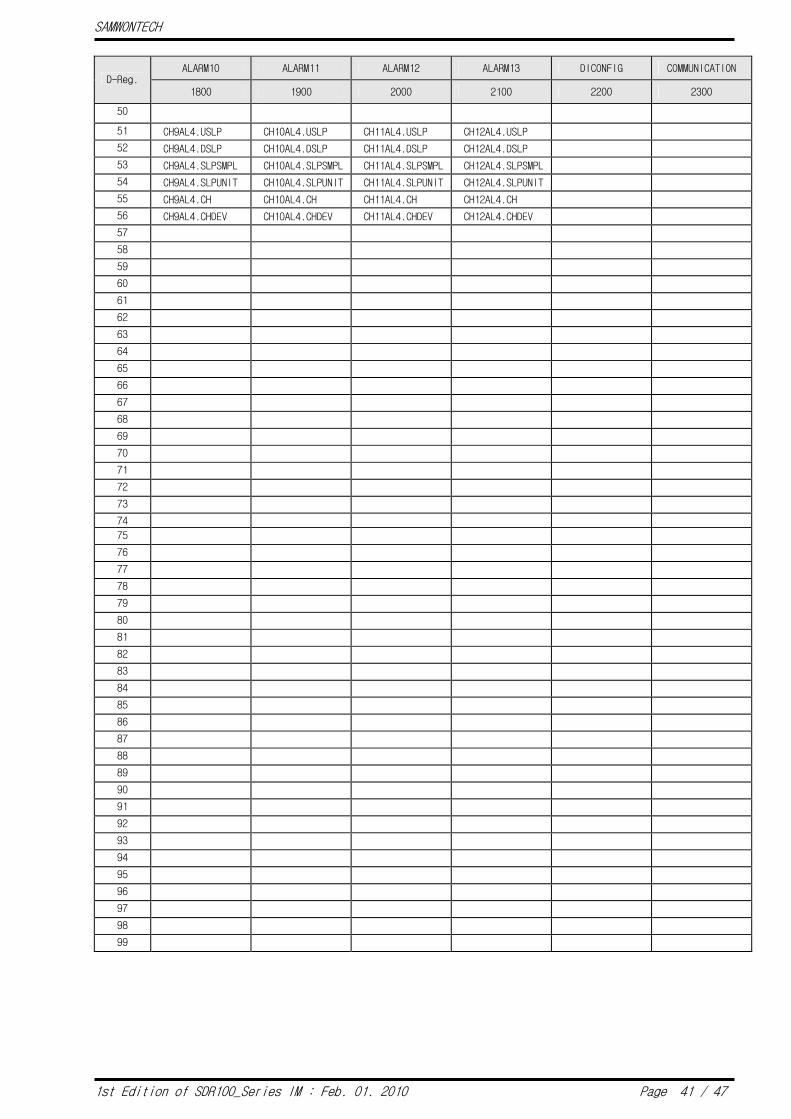
ALARM10 ALARM11 ALARM12 ALARM13 DICONFIG COMMUNICATION D-Reg.
1800 1900 2000 2100 2200 2300
50
51 CH9AL4.USLP CH10AL4.USLP CH11AL4.USLP CH12AL4.USLP
52 CH9AL4.DSLP CH10AL4.DSLP CH11AL4.DSLP CH12AL4.DSLP
53 CH9AL4.SLPSMPL CH10AL4.SLPSMPL CH11AL4.SLPSMPL CH12AL4.SLPSMPL
54 CH9AL4.SLPUNIT CH10AL4.SLPUNIT CH11AL4.SLPUNIT CH12AL4.SLPUNIT
55 CH9AL4.CH CH10AL4.CH CH11AL4.CH CH12AL4.CH
56 CH9AL4.CHDEV CH10AL4.CHDEV CH11AL4.CHDEV CH12AL4.CHDEV
57
58
59
60
61
62
63
64
65
66
67
68
69
70
71
72
73
74
75
76
77
78
79
80
81
82
83
84
85
86
87
88
89
90
91
92
93
94
95
96
97
98
99

SAMWONTECH
1st Edition of SDR100_Series IM : Feb. 01. 2010 Page 42 / 47
D-Register 2400 ~ 2999
PICTURE INITIAL ERROR HISTORY1 ERROR HISTORY2 ERROR HISTORY3 ERROR HISTORY4 D-Reg.
2400 2500 2600 2700 2800 2900
0
1 VIEW.ROTATE LANGUAGE ERRTM1.YEAR
2 R.ST_TIME DISP.MODE ERRTM1.MONTH
3 R.INT_TIME ERRTM1.DAY
4 ERRTM1.HOUR
5 ERRTM1.MIN
6 INFORM1.NAME1 ERRTM1.SEC
7 INFORM1.NAME2 ERROR1.CODE
ERROR 15 ERROR 29 ERROR 43
8 INFORM1.NAME3 ERRTM2.YEAR
9 INFORM1.NAME4 ERRTM2.MONTH
10 INFORM1.NAME5 ERRTM2.DAY
11 INFORM1.NAME6 ERRTM2.HOUR
12 INFORM1.NAME7 ERRTM2.MIN
13 INFORM1.NAME8 ERRTM2.SEC
14 INFORM1.NAME9 ERROR2.CODE
ERROR 16 ERROR 30 ERROR 44
15 INFORM1.NAME10 ERRTM3.YEAR
16 INFORM1.NAME11 ERRTM3.MONTH
17 INFORM1.NAME12 ERRTM3.DAY
18 INFORM1.NAME13 ERRTM3.HOUR
19 INFORM2.NAME1 ERRTM3.MIN
20 INFORM2.NAME2 ERRTM3.SEC
21 INFORM2.NAME3 ERROR3.CODE
ERROR 17 ERROR 31 ERROR 45
22 INFORM2.NAME4 ERRTM4.YEAR
23 INFORM2.NAME5 ERRTM4.MONTH
24 INFORM2.NAME6 ERRTM4.DAY
25 INFORM2.NAME7 ERRTM4.HOUR
26 INFORM2.NAME8 ERRTM4.MIN
27 INFORM2.NAME9 ERRTM4.SEC
28 INFORM2.NAME10 ERROR4.CODE
ERROR 18 ERROR 32 ERROR 46
29 INFORM2.NAME11 ERRTM5.YEAR
30 INFORM2.NAME12 ERRTM5.MONTH
31 INFORM2.NAME13 ERRTM5.DAY
32 INFORM3.NAME1 ERRTM5.HOUR
33 INFORM3.NAME2 ERRTM5.MIN
34 INFORM3.NAME3 ERRTM5.SEC
35 INFORM3.NAME4 ERROR5.CODE
ERROR 19 ERROR 33 ERROR 47
36 INFORM3.NAME5 ERRTM6.YEAR
37 INFORM3.NAME6 ERRTM6.MONTH
38 INFORM3.NAME7 ERRTM6.DAY
39 INFORM3.NAME8 ERRTM6.HOUR
40 INFORM3.NAME9 ERRTM6.MIN
41 INFORM3.NAME10 ERRTM6.SEC
42 INFORM3.NAME11 ERROR6.CODE
ERROR 20 ERROR 34 ERROR 48
43 INFORM3.NAME12 ERRTM7.YEAR
44 INFORM3.NAME13 ERRTM7.MONTH
45 ERRTM7.DAY
46 ERRTM7.HOUR
47 ERRTM7.MIN
48 ERRTM7.SEC
49 ERROR7.CODE
ERROR 21 ERROR 35 ERROR 49
SAMWONTECH
1st Edition of SDR100_Series IM : Feb. 01. 2010 Page 43 / 47
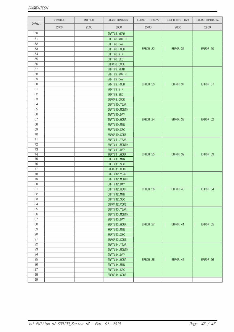
PICTURE INITIAL ERROR HISTORY1 ERROR HISTORY2 ERROR HISTORY3 ERROR HISTORY4 D-Reg.
2400 2500 2600 2700 2800 2900
50 ERRTM8.YEAR
51 ERRTM8.MONTH
52 ERRTM8.DAY
53 ERRTM8.HOUR
54 ERRTM8.MIN
55 ERRTM8.SEC
56 ERROR8.CODE
ERROR 22 ERROR 36 ERROR 50
57 ERRTM9.YEAR
58 ERRTM9.MONTH
59 ERRTM9.DAY
60 ERRTM9.HOUR
61 ERRTM9.MIN
62 ERRTM9.SEC
63 ERROR9.CODE
ERROR 23 ERROR 37 ERROR 51
64 ERRTM10.YEAR
65 ERRTM10.MONTH
66 ERRTM10.DAY
67 ERRTM10.HOUR
68 ERRTM10.MIN
69 ERRTM10.SEC
70 ERROR10.CODE
ERROR 24 ERROR 38 ERROR 52
71 ERRTM11.YEAR
72 ERRTM11.MONTH
73 ERRTM11.DAY
74 ERRTM11.HOUR
75 ERRTM11.MIN
76 ERRTM11.SEC
77 ERROR11.CODE
ERROR 25 ERROR 39 ERROR 53
78 ERRTM12.YEAR
79 ERRTM12.MONTH
80 ERRTM12.DAY
81 ERRTM12.HOUR
82 ERRTM12.MIN
83 ERRTM12.SEC
84 ERROR12.CODE
ERROR 26 ERROR 40 ERROR 54
85 ERRTM13.YEAR
86 ERRTM13.MONTH
87 ERRTM13.DAY
88 ERRTM13.HOUR
89 ERRTM13.MIN
90 ERRTM13.SEC
91 ERROR13.CODE
ERROR 27 ERROR 41 ERROR 55
92 ERRTM14.YEAR
93 ERRTM14.MONTH
94 ERRTM14.DAY
95 ERRTM14.HOUR
96 ERRTM14.MIN
97 ERRTM14.SEC
98 ERROR14.CODE
ERROR 28 ERROR 42 ERROR 56
99
SAMWONTECH
1st Edition of SDR100_Series IM : Feb. 01. 2010 Page 44 / 47
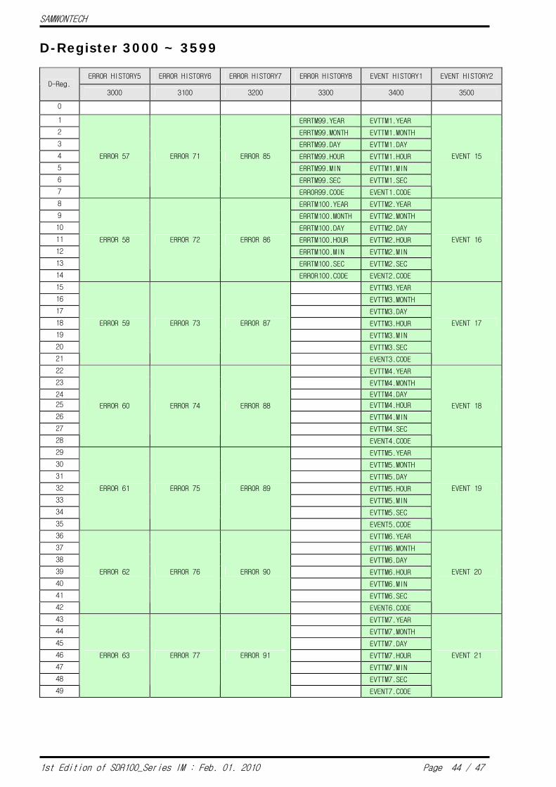
D-Register 3000 ~ 3599
ERROR HISTORY5 ERROR HISTORY6 ERROR HISTORY7 ERROR HISTORY8 EVENT HISTORY1 EVENT HISTORY2 D-Reg.
3000 3100 3200 3300 3400 3500
0
1 ERRTM99.YEAR EVTTM1.YEAR
2 ERRTM99.MONTH EVTTM1.MONTH
3 ERRTM99.DAY EVTTM1.DAY
4 ERRTM99.HOUR EVTTM1.HOUR
5 ERRTM99.MIN EVTTM1.MIN
6 ERRTM99.SEC EVTTM1.SEC
7
ERROR 57 ERROR 71 ERROR 85
ERROR99.CODE EVENT1.CODE
EVENT 15
8 ERRTM100.YEAR EVTTM2.YEAR
9 ERRTM100.MONTH EVTTM2.MONTH
10 ERRTM100.DAY EVTTM2.DAY
11 ERRTM100.HOUR EVTTM2.HOUR
12 ERRTM100.MIN EVTTM2.MIN
13 ERRTM100.SEC EVTTM2.SEC
14
ERROR 58 ERROR 72 ERROR 86
ERROR100.CODE EVENT2.CODE
EVENT 16
15 EVTTM3.YEAR
16 EVTTM3.MONTH
17 EVTTM3.DAY
18 EVTTM3.HOUR
19 EVTTM3.MIN
20 EVTTM3.SEC
21
ERROR 59 ERROR 73 ERROR 87
EVENT3.CODE
EVENT 17
22 EVTTM4.YEAR
23 EVTTM4.MONTH
24 EVTTM4.DAY
25 EVTTM4.HOUR
26 EVTTM4.MIN
27 EVTTM4.SEC
28
ERROR 60 ERROR 74 ERROR 88
EVENT4.CODE
EVENT 18
29 EVTTM5.YEAR
30 EVTTM5.MONTH
31 EVTTM5.DAY
32 EVTTM5.HOUR
33 EVTTM5.MIN
34 EVTTM5.SEC
35
ERROR 61 ERROR 75 ERROR 89
EVENT5.CODE
EVENT 19
36 EVTTM6.YEAR
37 EVTTM6.MONTH
38 EVTTM6.DAY
39 EVTTM6.HOUR
40 EVTTM6.MIN
41 EVTTM6.SEC
42
ERROR 62 ERROR 76 ERROR 90
EVENT6.CODE
EVENT 20
43 EVTTM7.YEAR
44 EVTTM7.MONTH
45 EVTTM7.DAY
46 EVTTM7.HOUR
47 EVTTM7.MIN
48 EVTTM7.SEC
49
ERROR 63 ERROR 77 ERROR 91
EVENT7.CODE
EVENT 21

SAMWONTECH
1st Edition of SDR100_Series IM : Feb. 01. 2010 Page 45 / 47
ERROR HISTORY5 ERROR HISTORY6 ERROR HISTORY7 ERROR HISTORY8 EVENT HISTORY1 EVENT HISTORY2 D-Reg.
3000 3100 3200 3300 3400 3500
50 EVTTM8.YEAR
51 EVTTM8.MONTH
52 EVTTM8.DAY
53 EVTTM8.HOUR
54 EVTTM8.MIN
55 EVTTM8.SEC
56
ERROR 64 ERROR 78 ERROR 92
EVENT8.CODE
EVENT 22
57 EVTTM9.YEAR
58 EVTTM9.MONTH
59 EVTTM9.DAY
60 EVTTM9.HOUR
61 EVTTM9.MIN
62 EVTTM9.SEC
63
ERROR 65 ERROR 79 ERROR 93
EVENT9.CODE
EVENT 23
64 EVTTM10.YEAR
65 EVTTM10.MONTH
66 EVTTM10.DAY
67 EVTTM10.HOUR
68 EVTTM10.MIN
69 EVTTM10.SEC
70
ERROR 66 ERROR 80 ERROR 94
EVENT10.CODE
EVENT 24
71 EVTTM11.YEAR
72 EVTTM11.MONTH
73 EVTTM11.DAY
74 EVTTM11.HOUR
75 EVTTM11.MIN
76 EVTTM11.SEC
77
ERROR 67 ERROR 81 ERROR 95
EVENT11.CODE
EVENT 25
78 EVTTM12.YEAR
79 EVTTM12.MONTH
80 EVTTM12.DAY
81 EVTTM12.HOUR
82 EVTTM12.MIN
83 EVTTM12.SEC
84
ERROR 68 ERROR 82 ERROR 96
EVENT12.CODE
EVENT 26
85 EVTTM13.YEAR
86 EVTTM13.MONTH
87 EVTTM13.DAY
88 EVTTM13.HOUR
89 EVTTM13.MIN
90 EVTTM13.SEC
91
ERROR 69 ERROR 83 ERROR 97
EVENT13.CODE
EVENT 27
92 EVTTM14.YEAR
93 EVTTM14.MONTH
94 EVTTM14.DAY
95 EVTTM14.HOUR
96 EVTTM14.MIN
97 EVTTM14.SEC
98
ERROR 70 ERROR 84 ERROR 98
EVENT14.CODE
EVENT 28
99

SAMWONTECH
1st Edition of SDR100_Series IM : Feb. 01. 2010 Page 46 / 47
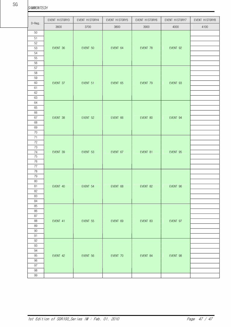
D-Register 3600 ~ 4199
EVENT HISTORY3 EVENT HISTORY4 EVENT HISTORY5 EVENT HISTORY6 EVENT HISTORY7 EVENT HISTORY8 D-Reg.
3600 3700 3800 3900 4000 4100
0
1 EVTTM99.YEAR
2 EVTTM99.MONTH
3 EVTTM99.DAY
4 EVTTM99.HOUR
5 EVTTM99.MIN
6 EVTTM99.SEC
7
EVENT 29 EVENT 43 EVENT 57 EVENT 71 EVENT 85
EVENT99.CODE
8 EVTTM100.YEAR
9 EVTTM100.MONTH
10 EVTTM100.DAY
11 EVTTM100.HOUR
12 EVTTM100.MIN
13 EVTTM100.SEC
14
EVENT 30 EVENT 44 EVENT 58 EVENT 72 EVENT 86
EVENT100.CODE
15
16
17
18
19
20
21
EVENT 31 EVENT 45 EVENT 59 EVENT 73 EVENT 87
22
23
24
25
26
27
28
EVENT 32 EVENT 46 EVENT 60 EVENT 74 EVENT 88
29
30
31
32
33
34
35
EVENT 33 EVENT 47 EVENT 61 EVENT 75 EVENT 89
36
37
38
39
40
41
42
EVENT 34 EVENT 48 EVENT 62 EVENT 76 EVENT 90
43
44
45
46
47
48
49
EVENT 35 EVENT 49 EVENT 63 EVENT 77 EVENT 91
SAMWONTECH
1st Edition of SDR100_Series IM : Feb. 01. 2010 Page 47 / 47
EVENT HISTORY3 EVENT HISTORY4 EVENT HISTORY5 EVENT HISTORY6 EVENT HISTORY7 EVENT HISTORY8 D-Reg.
3600 3700 3800 3900 4000 4100
50
51
52
53
54
55
56
EVENT 36 EVENT 50 EVENT 64 EVENT 78 EVENT 92
57
58
59
60
61
62
63
EVENT 37 EVENT 51 EVENT 65 EVENT 79 EVENT 93
64
65
66
67
68
69
70
EVENT 38 EVENT 52 EVENT 66 EVENT 80 EVENT 94
71
72
73
74
75
76
77
EVENT 39 EVENT 53 EVENT 67 EVENT 81 EVENT 95
78
79
80
81
82
83
84
EVENT 40 EVENT 54 EVENT 68 EVENT 82 EVENT 96
85
86
87
88
89
90
91
EVENT 41 EVENT 55 EVENT 69 EVENT 83 EVENT 97
92
93
94
95
96
97
98
EVENT 42 EVENT 56 EVENT 70 EVENT 84 EVENT 98
99
SG

Please contact our Sales Department for Product
Inquiry and Technical Consultant.
.
SAMWONTECH CO.,LTD.
192, Yakdae-dong, Wonmi-gu, Bucheon
City,Gyeonggi-do
202-703, Bucheon TechnoPark
TEL : 032-326-9120
FAX : 032-326-9119
http://www.samwontech.com
E-mail:[email protected]
This Manual may be changed without prior notice. 1st Edition issued on Feb. 2010
This Manual is not allowed to copy, edit whole or partial in any type without written notice from SAMWONTECH.


![INDEX [archive.acscricket.com]...1 Electrical Trades Comm Tvllrs Assocn Bookham Bookham 1951 ENG Scores 1 3 Royal Warwickshire Regmtl Assocn Rowland United Rugby 1951 ENG CA Note also](https://static.fdocuments.in/doc/165x107/5f13cf971159876eb9169b69/index-1-electrical-trades-comm-tvllrs-assocn-bookham-bookham-1951-eng-scores.jpg)