SD 104 Moisture-Density Relations of Soils, Aggregates ...012)sd104.pdfAASHTO T 99. 2.2 Rammer. A...
18
SD 104 mso.mat 9-17 Moisture-Density Relations of Soils, Aggregates, and Specified Mixtures 1. Scope: This test is to establish the moisture-density relationship of soils, aggregates and mixtures. NOTE: Before field control of compaction can be exercised, it is required that the optimum moisture, maximum density values (4-point Method) be determined for the materials prior to, or at the time field compactions are measured. The purpose of the 4-point determination is to verify if a family of curves is usable for the material. Changing from one family of curves to the other family of curves requires a 4-point determination to validate the change. Definitions. Compaction: The act of increasing the unit weight of the soil, aggregate or mixture, by mechanically compressing the material into a closer state of contact. For a given compactive effort, the density of the material tested will normally increase until optimum moisture content is reached, then the density will begin to decrease. It should be noted that there have been cases where the apparent decrease in density was followed by another increase in density. These secondary or "False" plateaus in the moisture-density curve should always be checked to determine the valid data. The Percent Compaction: This is the ratio of the density of the material, as placed during construction, to the maximum density of a representative specimen of the same material. Density: The density of a material is the weight per unit volume, in lbs./ft 3 in dry condition. One-Point (Standard) Test: A rapid test where the wet density and moisture content measurements for the test material are used to select a curve from a family of curves to be the standard. Four-Point (Standard) Test: The results of four or more moisture-density tests are plotted with density values as the ordinate or vertical scale and the moisture content (Percentage) as the abscissas or horizontal scale. When the plotted points are joined by a smooth curve, the maximum density at optimum moisture may be determined. (Figure 2, 3, 5 and 6) The moisture content corresponding to the peak of the curve shall be termed “Optimum Moisture” of the material . The dry density in lbs./ft 3 at optimum moisture content shall be termed the “Maximum Density”.
Transcript of SD 104 Moisture-Density Relations of Soils, Aggregates ...012)sd104.pdfAASHTO T 99. 2.2 Rammer. A...

SD 104
mso.mat 9-17
Moisture-Density Relations of Soils, Aggregates, and Specified Mixtures
1. Scope: This test is to establish the moisture-density relationship of soils, aggregates and
mixtures.
NOTE: Before field control of compaction can be exercised, it is required that the optimum moisture, maximum density values (4-point Method) be determined for the materials prior to, or at the time field compactions are measured. The purpose of the 4-point determination is to verify if a family of curves is usable for the material. Changing from one family of curves to the other family of curves requires a 4-point determination to validate the change.
Definitions. Compaction: The act of increasing the unit weight of the soil, aggregate or mixture,
by mechanically compressing the material into a closer state of contact. For a given compactive effort, the density of the material tested will normally increase until optimum moisture content is reached, then the density will begin to decrease. It should be noted that there have been cases where the apparent decrease in density was followed by another increase in density. These secondary or "False" plateaus in the moisture-density curve should always be checked to determine the valid data.
The Percent Compaction: This is the ratio of the density of the material, as placed
during construction, to the maximum density of a representative specimen of the same material.
Density: The density of a material is the weight per unit volume, in lbs./ft
3 in dry
condition. One-Point (Standard) Test: A rapid test where the wet density and moisture content
measurements for the test material are used to select a curve from a family of curves to be the standard.
Four-Point (Standard) Test: The results of four or more moisture-density tests are
plotted with density values as the ordinate or vertical scale and the moisture content (Percentage) as the abscissas or horizontal scale. When the plotted points are joined by a smooth curve, the maximum density at optimum moisture may be determined. (Figure 2, 3, 5 and 6) The moisture content corresponding to the peak of the curve shall be termed “Optimum Moisture” of the material. The dry density in lbs./ft
3 at optimum moisture content shall be termed the “Maximum Density”.

SD 104 Page 2
mso.mat 9-17
Optimum Moisture: The moisture content corresponding to the maximum density.
Maximum Density: The highest value for density, calculated on the basis of dry weight of material per cubic foot, shown on the moisture density curve.
2. Apparatus:
2.1 Molds. A 4" diameter or 6" diameter mold meeting the requirements of AASHTO T 99.
2.2 Rammer. A 5.5 lb. rammer conforming to AASHTO T 99.
NOTE: A mechanical rammer may be used, if approved by the Chief Materials and Surfacing Engineer.
2.3 Sample extruder (Optional) such as a jack, frame, or other device adapted for
extruding compacted specimens from the mold.
2.4 Scale or balance having the capacity to weigh any sample which may be tested utilizing this procedure and readable to the nearest 0.01 lb. and also one that is readable to the nearest 0.1 gram.
2.5 Sieves and screens. A 3/4" and a #4 sieve. A #4 rough screen shall be approximately 12" x 18" in size. #4 sieves intended for use in sieve analysis testing shall not be used for pushing wet material through as shown in paragraph 3.2 B.
2.6 Oven.
A. An oven, for determining moisture content, capable of maintaining a
temperature of 230 ± 9F.
B. An oven for drying soil samples at a temperature not exceeding 140F. NOTE: Other methods of moisture determination shown in SD 108 may be used.
2.7 Containers for moisture content samples. 2.8 Steel straightedge at least 12" in length.
2.9 Miscellaneous: Tools, plastic bags, beakers, cans, pails, shovel, spatula, knife, spoons and trowel.

SD 104 Page 3
mso.mat 9-17
3. Procedure:
Method 1 Four Point - For testing materials passing a #4 sieve using a 4" mold. Method 2 One Point - For testing material passing a #4 sieve using a 4” mold. Method 3 Four Point - For testing material passing a 3/4” sieve using a 6” mold. Method 4 One Point - For testing material passing a 3/4” sieve using a 6” mold.
NOTE: The method used for determining the 4-point will establish the method used for the 1-point, i.e., if the 4" mold is used for the 4-point, (Method 1) the 4" mold must be used for the 1-point (Method 2). If it is requested to change mold size, a 4-point using that size mold must be completed. The mold without the collar shall be weighed to the nearest 0.01 lb., prior to beginning the test.
3.1 Method 1 (Soil).
A. Obtain a sample of soil weighing approximately 30 lbs.
B. Dry the sample in an oven at a temperature not exceeding 140F.
C. Using the apparatus described in SD 101, break the sample down to pass the #4 sieve. Care must be taken not to break any rock retained on the #4 sieve. Sieve the sample on a #4 sieve and discard any granular material retained.
D. Reduce the sample to 5 specimens, weighing approximately 5 lbs.
each.
E. Thoroughly mix one of the specimens with a measured amount of water to dampen it to approximately 4 to 6 percentage points below optimum.
F. Place the specimen in a plastic bag and seal the top to prevent
moisture loss. Allow the specimen to cure for a minimum of 12 hours.
G. Mix the remaining specimens in the same manner as shown in paragraphs E. and F., increasing the measured water by approximately 2 percentage points over the preceding specimen. The percent of increase should be at a uniform rate.
H. The test specimen is then formed in the 4" mold, with collar attached,
in three approximately equal layers, to a total compacted depth of approximately 5". Compact each layer using 25 uniformly distributed blows from the rammer dropping free from a height of 12" above the surface of the soil in the mold. Clean rammer head prior to compacting the next layer to ensure the calibrated rammer head is still 5.5 lbs.
SD 104 Page 4
mso.mat 9-17
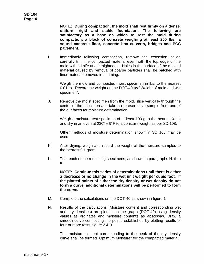
NOTE: During compaction, the mold shall rest firmly on a dense, uniform rigid and stable foundation. The following are satisfactory as a base on which to rest the mold during compaction: a block of concrete weighing at least 200 lbs., a sound concrete floor, concrete box culverts, bridges and PCC pavement.
I. Immediately following compaction, remove the extension collar,
carefully trim the compacted material even with the top edge of the mold with a knife and straightedge. Holes in the surface of the molded material caused by removal of coarse particles shall be patched with finer material removed in trimming.
Weigh the mold and compacted moist specimen in lbs. to the nearest 0.01 lb. Record the weight on the DOT-40 as "Weight of mold and wet specimen".
J. Remove the moist specimen from the mold, slice vertically through the
center of the specimen and take a representative sample from one of the cut faces for moisture determination.
Weigh a moisture test specimen of at least 100 g to the nearest 0.1 g
and dry in an oven at 230 9F to a constant weight as per SD 108.
Other methods of moisture determination shown in SD 108 may be used.
K. After drying, weigh and record the weight of the moisture samples to
the nearest 0.1 gram.
L. Test each of the remaining specimens, as shown in paragraphs H. thru K.
NOTE: Continue this series of determinations until there is either a decrease or no change in the wet unit weight per cubic foot. If the plotted points of either the dry density or wet density do not form a curve, additional determinations will be performed to form the curve.
M. Complete the calculations on the DOT-40 as shown in figure 1. N. Results of the calculations (Moisture content and corresponding wet
and dry densities) are plotted on the graph (DOT-40) using density values as ordinates and moisture contents as abscissas. Draw a smooth curve connecting the points established by plotting results of four or more tests, figure 2 & 3.
The moisture content corresponding to the peak of the dry density
curve shall be termed "Optimum Moisture" for the compacted material.
SD 104 Page 5
mso.mat 9-17
O. The dry unit weight density lbs./ft
3 of the compacted material at
optimum moisture content shall be termed “Maximum Density”. P. Validation of the family of curves: Prior to using any family of pre-
drawn curves, it shall be checked using project material and the 4-point system. This can be done by comparison of wet density curves.
1. Determine the maximum dry density and optimum moisture from
the 4-point dry density curve. This should be at the peak of the dry density curve.
2. Select a moisture content 1 1/2 to 2 percentage points below
optimum moisture. 3. Using this moisture content, find the corresponding wet density
on the wet density curve of the 4-point. 4. Plot this wet density and moisture content on the family of curves
proposed for use on the project to determine the curve to be used for the standard.
Select the curve nearest the plotted point. If the plotted point is between 2 curves and there is doubt as to which curve is closest, use the curve below the plot.
The maximum dry density from this curve must be within 3 lbs. of the 4-point maximum dry density. If the curves fail to check within this tolerance, contact the Region Materials Engineer as the family of curves may not be reliable for this material.
3.2 Method 2 (Soil).
A. Obtain a sample of approximately 5 lbs. of soil.
B. Break up the sample using fingers, a trowel or a pine board to push the
sample through a #4 rough screen. C. If the sample appears to be above optimum moisture, dry it sufficiently
in an oven at a temperature not exceeding 140° F to bring it to approximately optimum.
If the sample appears too dry, add and mix sufficient water to bring it
near optimum. D. Mold and take a moisture sample, as shown in paragraphs 3.1 H
through 3.1 J. (Use form DOT-35 for moisture tests and DOT-41 for density tests.)

SD 104 Page 6
mso.mat 9-17
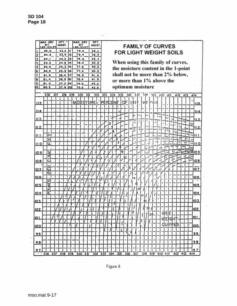
E. Using the “1-point determination” wet density and the “1-point” moisture determination, enter the family of curves, figure 7 or figure 8, to obtain the maximum density and optimum moisture. The family of curves must be the one identified by the 4-point determination. (See “NOTE” on page 1 of this procedure.)
Select the curve nearest the plotted point. If the plotted point is
between 2 curves and there is doubt as to which curve is closest, use the curve below the plot.
NOTE: If the 1-point moisture content deviates from optimum (for the curve selected) by more than 2 percentage points below or 1 percentage point above, a second 1-point shall be made at or nearer optimum and within the tolerance shown.
3.3 Method 3 (Soils and/or Granular Material).
A. Obtain a sample of approximately 60 lbs. in accordance with SD 201.
NOTE: The tester may elect to obtain more material and mix individual samples at varying percentages of moisture. If so elected, follow the procedure shown in method 1 and obtain samples approximately 15 lbs. each and use a 3/4" sieve and a 6" mold.
B. Dry the sample in an oven at a temperature not exceeding 140° F.
C. Sieve the sample on a 3/4" sieve, discarding the material retained.
D. Weigh the sample and add sufficient water to bring it to approximately 4 percentage points below optimum.
E. The test specimen is then formed in the 6" mold in three approximately
equal layers to a total depth of approximately 5". Compact each layer using 56 uniformly distributed blows from the rammer dropping 12" above the surface of the material in the mold. Clean rammer head prior to compacting the next layer to ensure the calibrated rammer head is still 5.5 lbs. NOTE: During compaction, the mold shall rest firmly on a dense, uniform, rigid and stable foundation. The following are satisfactory bases on which to rest the mold during compaction: A block of concrete weighing at least 200 lbs., a sound concrete floor, concrete box culverts, bridges and PCC pavement.
F. Immediately following compaction, remove the extension collar and
carefully trim the compacted material even with the top edge of the mold with a straightedge. Holes in the surface of the molded material

SD 104 Page 7
mso.mat 9-17
caused by removal of coarse particles shall be patched with finer material removed in trimming.
Weigh the mold and compacted moist specimen in lbs. to the nearest
0.01 lb. Record on a DOT-40 as "Weight of mold and wet specimen".
G. Remove the specimen from the mold, slice vertically through the center of the specimen and take a representative sample from one cut face for moisture determination.
Weigh a moisture test specimen of at least 100 grams for soil and 500
grams for granular material to the nearest 0.1 g and dry in an oven at a
temperature of 230 9F to a constant weight as per SD 108.
Other methods of moisture determination as shown in SD 108 may be used.
H. After drying, weigh and record the weights of the moisture sample to
the nearest 0.1 gram.
I. Complete the calculation on the DOT-40 as shown in figure 4.
J. Thoroughly break up the remaining portion of the specimen until it will pass a 3/4" sieve, and add it to the remaining portion of the sample being tested. Add sufficient water to increase moisture content of the sample between 1 and 2 percentage points and repeat the procedure in paragraphs 3.3 E. through 3.3 I.
NOTE: Continue this series of determinations until there is either a decrease or no change in the wet unit weight per cubic foot. If the plotted points of either the dry density or wet density do not form a curve, additional determinations will be performed to form the curve.
K. Results of calculations (Moisture content and corresponding wet and
dry densities) are plotted on the graph using density values as ordinates and moisture contents as abscissas. Draw a smooth curve connecting the points established by plotting results of 4 or more tests. (Figure 5 & 6).
L. The moisture content corresponding to the peak of the dry density
curve shall be termed "Optimum Moisture" for the compacted material.
M. The dry unit weight corresponding to the peak of the dry density curve shall be termed "Maximum Density" of the compacted material.
N. Prior to using any family of pre-drawn curves, it shall be checked,
using project material and the 4-point system. This can be done by comparison of the wet density curves.

SD 104 Page 8
mso.mat 9-17
1. Determine the maximum dry density and optimum moisture from
the 4-point dry density curve. This should be at the peak of the dry density curve.
2. Select a moisture content 1 1/2 to 2 percentage points below
optimum moisture. 3. Using this moisture content, find the corresponding wet density
on the wet density curve of the 4-point. 4. Locate the wet density and moisture content on the family of
curves proposed for use on the project to determine the curve to be used for the standard.
Select the curve nearest the point. If the point is between 2 curves
and there is doubt as to which curve is closest, use the curve below the point.
The maximum dry density from this curve must be within ± 3 lbs./cu. ft.
of the 4-point maximum dry density. If the curves fail to check within this tolerance, contact the Region Materials Engineer as the family of curves may not be reliable for this material.
3.4 Method 4 (Soils and/or Granular Material).
A. Obtain a sample of approximately 15 Ibs.
B. Sieve the sample on a 3/4" sieve and discard any material retained.
C. If the sample appears to be above optimum moisture, dry it sufficiently in an oven at a temperature not exceeding 140° F to bring it to approximately optimum.
If the sample appears dry, add and mix sufficient water to bring it near
optimum.
D. Mold and take a moisture sample, as shown in paragraphs 3.3 E. through 3.3 I. (Use the DOT-41 for density tests.)
E. Using the “1-point determination” wet density and the “1-point”
moisture determination, enter the family of curves figure 7 or figure 8 to obtain the maximum density and optimum moisture.
The family of curves must be the one identified by the 4-point
determination. (See “NOTE” on page 1 of this procedure.)

SD 104 Page 9
mso.mat 9-17
Select the curve nearest the plotted point. If the plotted point is between 2 curves and there is doubt as to which curve is closest, use the curve below the plot.
NOTE: Base course & subbase construction: When the moisture in the 1-point determination deviates more than 2 percentage points below or 1 percentage point above optimum moisture, another 1-point (nearer to optimum moisture) shall be made. If the Maximum density deviates more than 3 lbs. from the 4-point range, the Region Materials Engineer shall be contacted.
When changes in gradation occur which may affect density results,
additional 4-point determinations shall be made, as directed by the Region Materials Engineer.
3.5 When Methods 2 and 4 are used in conjunction with SD 105 and SD 106, the
material for testing is taken from or adjacent to the in-place density test hole and the DOT-41 form is used.
4. Report:
4.1 Calculations.
Calculate the moisture content and corresponding dry unit weight in lbs./ft3
as follows:
w = A - B x 100 B - C
and
W = W1 x 100
w + 100
Where:
w = Percentage of moisture in specimen, based on dry weight of soil.
A = Weight of container and wet soil/granular material.
B = Weight of container and dry soil/granular material.
C = Weight of container.
W = Dry weight in lbs./ft3 of compacted material.
W1 = Wet weight in lbs./ft
3 of compacted material.
4.2 Report.

SD 104 Page 10
mso.mat 9-17
A. Report the following:
(1) The optimum moisture content, as a percentage, to the nearest 0.1.
(2) The maximum density in lbs./ft
3 to the nearest 0.1 lb.
(3) Test results will be reported on form DOT-40.
5. References: AASHTO T 99 SD 101 SD 105 SD 106 SD 108 SD 201 SD 205 DOT-35 DOT-40 DOT-41

SD 104 Page 11
mso.mat 9-17
File No.
PROJECT IM 090-7(14)125 COUNTY Washington PCN
OPERATOR Marv C. Cleason CHECKED BY RJH DATE
Specimen
Number
Can
Number
Weight of Can
and Wet Material
Weight of Can
and Dry Material
Weight Loss (Moisture)
Speedy Reading
Weight of Can
Weight of Dry
Material
Percent
Moisture
Weight of Mold
and Wet Specimen
Weight of Mold
Weight of Wet
Specimen
Factor of
Mold No.
Wet Density Wet Wt. x Factor
Dry Density
PCF
DOT-40
9-14
16
SOUTH DAKOTA
DEPARTMENT OF TRANSPORATION
DENSITY SHEET
7140
8/8/96
5
9 3 2 48
1 2
PLOT WET AND DRY CURVES ON REVERSE SIDE
Figure 1
164.7 192.7 142.0 121.7 133.2
3 4
13.7 18.5 15.0 14.5
151.0 174.2 127.0 107.2 117.0
16.2
15.8
101.2
14.0 16.0
137.0 158.2 109.5 93.3
17.5 13.9
13.83 14.10 14.21 14.11
10.0 11.7 13.7 15.5 16.0
13.96
9.71
4.25
9.71 9.71
4.12 4.39 4.50 4.40
9.71 9.71
29.98 29.98 29.98 29.98
131.6 134.9 131.9 127.4
109.8
2-90
112.3 117.8 118.6 114.2
29.98
123.5

SD 104 Page 12
mso.mat 9-17

SD 104 Page 13
mso.mat 9-17

SD 104 Page 14
mso.mat 9-17

SD 104 Page 15
mso.mat 9-17

SD 104 Page 16
mso.mat 9-17

SD 104 Page 17
mso.mat 9-17
SD 104 Page 18
mso.mat 9-17