SCSR 1013 DIGITAL LOGIC FINAL EXAM 2015/2016-1
17
SCSR 1013 DIGITAL LOGIC FINAL EXAM 2015/2016-1 (1) OBJECTIVE QUESTIONS (30 POINTS) Answer the questions by filling your answers on PAGE 18. 1. Which of the following is NOT a latch? A. S-R latch B. J-K latch C. Gated S-R latch D. Gated D latch 2. The invalid state for S-R latch occurs when S and R are _______. A. both high B. both low C. S = high, R = low D. S = low, R = high 3. With regard to a D latch, ________. A. the Q output follows the D input when EN is LOW B. the Q output is opposite the D input when EN is LOW C. the Q output follows the D input when EN is HIGH D. the Q output is HIGH regardless of EN's input state 4. When both inputs of a J-K pulse-triggered flip-flop are LOW, and the clock triggers, what will the output be? A. An invalid state will exist. B. No change will occur in the output. C. The output will toggle. D. The output will reset.
Transcript of SCSR 1013 DIGITAL LOGIC FINAL EXAM 2015/2016-1

SCSR 1013 DIGITAL LOGIC FINAL EXAM 2015/2016-1
(1)
OBJECTIVE QUESTIONS (30 POINTS)
Answer the questions by filling your answers on PAGE 18.
1. Which of the following is NOT a latch?
A. S-R latch
B. J-K latch
C. Gated S-R latch
D. Gated D latch
2. The invalid state for S-R latch occurs when S and R are _______.
A. both high
B. both low
C. S = high, R = low
D. S = low, R = high
3. With regard to a D latch, ________.
A. the Q output follows the D input when EN is LOW
B. the Q output is opposite the D input when EN is LOW
C. the Q output follows the D input when EN is HIGH
D. the Q output is HIGH regardless of EN's input state
4. When both inputs of a J-K pulse-triggered flip-flop are LOW, and the clock triggers,
what will the output be?
A. An invalid state will exist.
B. No change will occur in the output.
C. The output will toggle.
D. The output will reset.
SCSR 1013 DIGITAL LOGIC FINAL EXAM 2015/2016-1
(2)
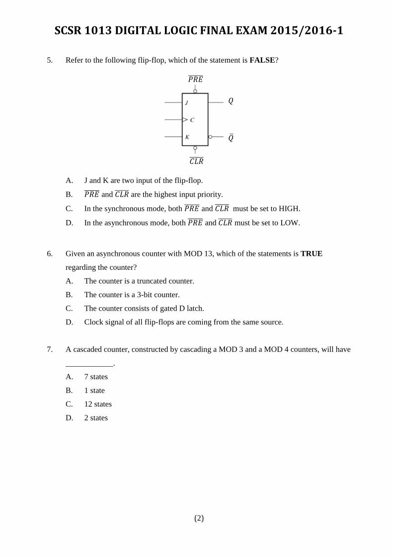
5. Refer to the following flip-flop, which of the statement is FALSE?
A. J and K are two input of the flip-flop.
B. 𝑃𝑅𝐸̅̅ ̅̅ ̅̅ and 𝐶𝐿𝑅̅̅ ̅̅ ̅̅ are the highest input priority.
C. In the synchronous mode, both 𝑃𝑅𝐸̅̅ ̅̅ ̅̅ and 𝐶𝐿𝑅̅̅ ̅̅ ̅̅ must be set to HIGH.
D. In the asynchronous mode, both 𝑃𝑅𝐸̅̅ ̅̅ ̅̅ and 𝐶𝐿𝑅̅̅ ̅̅ ̅̅ must be set to LOW.
6. Given an asynchronous counter with MOD 13, which of the statements is TRUE
regarding the counter?
A. The counter is a truncated counter.
B. The counter is a 3-bit counter.
C. The counter consists of gated D latch.
D. Clock signal of all flip-flops are coming from the same source.
7. A cascaded counter, constructed by cascading a MOD 3 and a MOD 4 counters, will have
____________.
A. 7 states
B. 1 state
C. 12 states
D. 2 states
Q �̅�
𝐶𝐿𝑅̅̅ ̅̅ ̅̅
𝑃𝑅𝐸̅̅ ̅̅ ̅̅

SCSR 1013 DIGITAL LOGIC FINAL EXAM 2015/2016-1
(3)
8. What is the clock maximum frequency limit of an asynchronous counter, which consists
of 4 Flip-Flop, with each FF propagation delay is equal to 4ms?
A. 62.5 Hz
B. 16 Hz
C. 0.25 Hz
D. 25 Hz
9. The last state of a modulus-11 binary counter is ________.
A. 1011
B. 1010
C. 1001
D. 1100
10. The designation 𝑈𝑃/𝐷𝑂𝑊𝑁̅̅ ̅̅ ̅̅ ̅̅ ̅ means that the ________.
A. up count is active-HIGH, the down count is active-LOW
B. up count is active-LOW, the down count is active-HIGH
C. up and down counts are both active-LOW
D. up and down counts are both active-HIGH
11. The sentence “the data only appear at the output in parallel, at the positive edge of the
clock” refers to
A. Serial In Serial Out (SISO) shift register
B. Single In Bit Out (SIBO) shift register
C. Parallel In Serial Out (PISO) shift register
D. Parallel In Parallel Out (PIPO) shift register

SCSR 1013 DIGITAL LOGIC FINAL EXAM 2015/2016-1
(4)
12. Choose the CORRECT sentence for 𝐿𝑂𝐴𝐷̅̅ ̅̅ ̅̅ ̅̅ :
A. When activated, the shift register will transfer any data from data input(s) into the
flip-flops.
B. When activated, the shift register will shift any data from data input(s) to the data
outputs.
C. When activated, the shift register will clear the flip-flops.
D. When activated, the shift register will toggle any data at the data outputs.
13. A bidirectional 4-bit shift register is storing the nibble 1101. Its 𝑅𝐼𝐺𝐻𝑇/𝐿𝐸𝐹𝑇̅̅ ̅̅ ̅̅ ̅̅ input is
HIGH. The nibble 1011 is waiting to be entered on the serial data-input line. After three
clock pulses, the shift register is storing ________.
A. 1101
B. 0111
C. 0001
D. 1110
14. On the fifth clock pulse, a 4-bit Johnson sequence is Q0 = 0, Q1 = 1, Q2 = 1, and Q3 = 1.
On the sixth clock pulse, the sequence is ________.
A. Q0 = 1, Q1 = 0, Q2 = 0, Q3 = 0
B. Q0 = 1, Q1 = 1, Q2 = 1, Q3 = 0
C. Q0 = 0, Q1 = 0, Q2 = 1, Q3 = 1
D. Q0 = 0, Q1 = 0, Q2 = 0, Q3 = 1
15. If a 10-bit Ring counter has an initial state 11 0100 0000, what is the state after the
second clock pulse?
A. 11 0100 0000
B. 00 1101 0000
C. 11 0000 0000
D. 00 0000 0000
SCSR 1013 DIGITAL LOGIC FINAL EXAM 2015/2016-1
(5)
16. The truth table for a full adder is shown below. What are the values of X, Y, and Z?
A B Cin Cout ∑
0 0 0 0 0
0 0 1 0 X
0 1 0 0 1
0 1 1 Y 0
1 0 0 0 1
1 0 1 1 0
1 1 0 1 0
1 1 1 1 Z
A. X = 0, Y = 1, Z = 1
B. X = 1, Y = 1, Z = 1
C. X = 1, Y = 0, Z = 1
D. X = 0, Y = 0, Z = 1
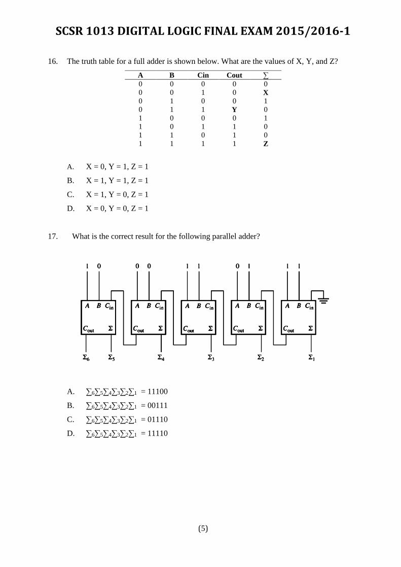
17. What is the correct result for the following parallel adder?
A. ∑6∑5∑4∑3∑2∑1 = 11100
B. ∑6∑5∑4∑3∑2∑1 = 00111
C. ∑6∑5∑4∑3∑2∑1 = 01110
D. ∑6∑5∑4∑3∑2∑1 = 11110

SCSR 1013 DIGITAL LOGIC FINAL EXAM 2015/2016-1
(6)
18. The binary numbers A = 1100 and B = 1001 are applied to the inputs of a comparator.
What are the output levels?
A. A > B = 1, A < B = 0, A < B = 1
B. A > B = 0, A < B = 1, A = B = 0
C. A > B = 1, A < B = 0, A = B = 0
D. A > B = 0, A < B = 1, A = B = 1
19. What type of device is shown below, and what inputs (A3, A2, A1, A0) are required to
produce the output levels as shown?
A. BCD-to-decimal encoder; 0,1,1,1
B. BCD-to-decimal encoder; 1,1,1,0
C. BCD-to-decimal decoder; 1,1,1,0
D. BCD-to-decimal decoder; 0,1,1,1
20. A priority encoder means that _________________.
A. the lowest priority goes first.
B. the highest input has priority.
C. priority is programmed into the device.
D. the lowest input has priority.
SCSR 1013 DIGITAL LOGIC FINAL EXAM 2015/2016-1
(7)
STRUCTURE QUESTIONS (70 POINTS)
QUESTION 1 (13 POINTS)
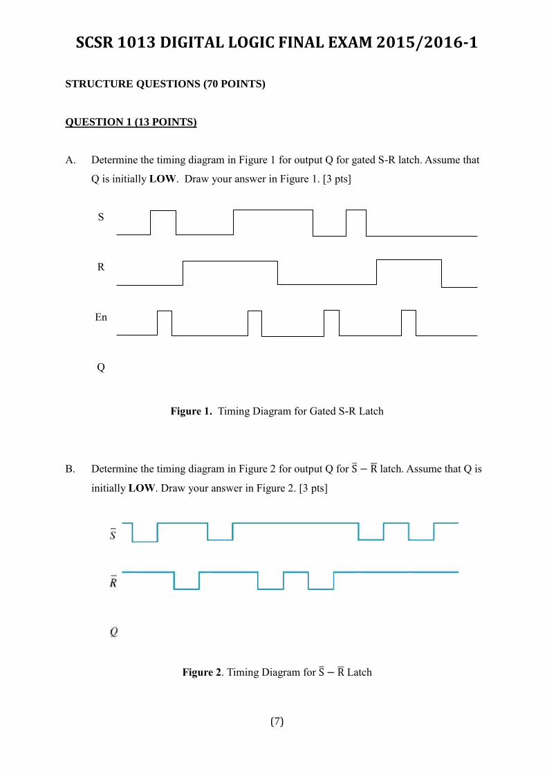
A. Determine the timing diagram in Figure 1 for output Q for gated S-R latch. Assume that
Q is initially LOW. Draw your answer in Figure 1. [3 pts]
S
R
En
Q
Figure 1. Timing Diagram for Gated S-R Latch
B. Determine the timing diagram in Figure 2 for output Q for S̅ − R̅ latch. Assume that Q is
initially LOW. Draw your answer in Figure 2. [3 pts]
Figure 2. Timing Diagram for S̅ − R̅ Latch

SCSR 1013 DIGITAL LOGIC FINAL EXAM 2015/2016-1
(8)
C. Refer to Figure 3. Given a positive edge triggered JK flip-flops, complete the following
timing diagram. [3 pts]
Figure 3
𝑃𝑅𝐸̅̅ ̅̅ ̅̅
𝐶𝐿𝑅̅̅ ̅̅ ̅̅
Clock
J
K
Q
𝑃𝑅𝐸̅̅ ̅̅ ̅̅
𝐶𝐿𝑅̅̅ ̅̅ ̅̅

SCSR 1013 DIGITAL LOGIC FINAL EXAM 2015/2016-1
(9)
D. Figure 4 shows two JK flip-flops, FF0 and FF1, with an input A and the outputs Q0 and
Q1. The input values of A changes according to Table 1.
Figure 4
i. For each of the changing, complete all inputs and output JK flip-flops values when clock
is triggered in Table 1. 𝑃𝑅𝐸̅̅ ̅̅ ̅̅ and 𝐶𝐿𝑅̅̅ ̅̅ ̅̅ are all set to HIGH and initial value for Q0 and Q1
are zero (0). [3 pts]
Table 1
CLK Input Flip-flop 0 (FF0) Flip-flop 1 (FF1) Output (FF0/FF1)
A J0 K0 J1 K1 Q0 Q1
- 0 0
1 1 1 1 0 1 1
0 0 0 0 1 1 0
ii. Based on Table 1, complete the following statement:
“JK flip-flop FF0 is acting as a _________ flip-flop while FF1 is performing as
________ flip-flop”. [1 pts]

SCSR 1013 DIGITAL LOGIC FINAL EXAM 2015/2016-1
(10)
QUESTION 2 (15 POINTS)
A. Design an asynchronous counter that has the following properties: [6 pts]
i. The counter is a MOD 6 counter.
ii. The counter sequence direction is counting up.
iii. The counter consists of active-low JK FF.
B. Consider a sequential circuit shown in Figure 5. It has one input X, one output Z and two
flip flops state variables Q2Q1. [9 pts]
Figure 5

SCSR 1013 DIGITAL LOGIC FINAL EXAM 2015/2016-1
(11)
Based on the circuit, derive: a. Boolean expression for input D1, D2 and output Z.
b. Next-state equations for output state Q2+ and Q1+.
c. Complete all possible values for the state table as shown in Table 2.
Table 2
Input,
X
Present State Next State Output,
Z Q2 Q1 Q2+ Q1+
SCSR 1013 DIGITAL LOGIC FINAL EXAM 2015/2016-1
(12)
QUESTION 3 (10 POINTS)
A. Draw 3-bit Ring Counter and Johnson Counter using D flip flop to show the significant
difference between them. [6 pts]
B. How many state produced for the 3-bit Johnson Counter and Ring Counter? [2 pts]
C. How to clear all output at once? [2 pts]
SCSR 1013 DIGITAL LOGIC FINAL EXAM 2015/2016-1
(13)
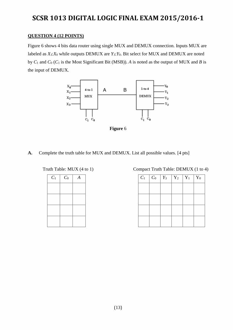
QUESTION 4 (12 POINTS)
Figure 6 shows 4 bits data router using single MUX and DEMUX connection. Inputs MUX are
labeled as X3:X0 while outputs DEMUX are Y3:Y0. Bit select for MUX and DEMUX are noted
by C1 and C0 (C1 is the Most Significant Bit (MSB)). A is noted as the output of MUX and B is
the input of DEMUX.
Figure 6
A. Complete the truth table for MUX and DEMUX. List all possible values. [4 pts]
Truth Table: MUX (4 to 1) Compact Truth Table: DEMUX (1 to 4)
C1 C0 A C1 C0 Y3 Y2 Y1 Y0
0 0 Xo 0 0 0 0 0 B
0 1 X1 0 1 0 0 B 0
1 0 X2 1 0 0 B 0 0
1 1 X3 1 1 B 0 0 0
SCSR 1013 DIGITAL LOGIC FINAL EXAM 2015/2016-1
(14)
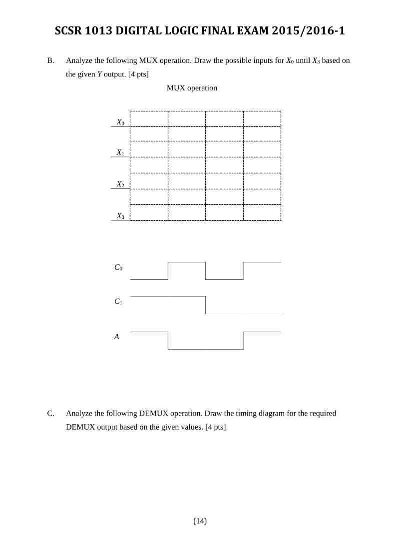
B. Analyze the following MUX operation. Draw the possible inputs for X0 until X3 based on
the given Y output. [4 pts]
MUX operation
X0
X1
X2
X3
C0
C1
A
C. Analyze the following DEMUX operation. Draw the timing diagram for the required
DEMUX output based on the given values. [4 pts]

SCSR 1013 DIGITAL LOGIC FINAL EXAM 2015/2016-1
(15)
DEMUX operation
B
C0
C1
Yo
Y1
Y2
Y3
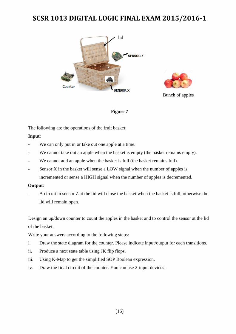
QUESTION 5 (20 POINTS)
Figure 7 shows a fruit basket that will be used to lift a bunch of apples to the main container.
The fruit basket can contain a maximum of 4 apples. Initially the fruit basket is empty. We
have a bunch of apples that we want to put into the basket one by one. Once the basket is full,
we have to lift the basket to the main container and pull out the apples one by one until the
basket is empty. Sensor X will sense the counting sequence of the counter while sensor Z
controls the movement of the lid.
SCSR 1013 DIGITAL LOGIC FINAL EXAM 2015/2016-1
(16)
Bunch of apples
Figure 7
The following are the operations of the fruit basket:
Input:
- We can only put in or take out one apple at a time.
- We cannot take out an apple when the basket is empty (the basket remains empty).
- We cannot add an apple when the basket is full (the basket remains full).
- Sensor X in the basket will sense a LOW signal when the number of apples is
incremented or sense a HIGH signal when the number of apples is decremented.
Output:
- A circuit in sensor Z at the lid will close the basket when the basket is full, otherwise the
lid will remain open.
Design an up/down counter to count the apples in the basket and to control the sensor at the lid
of the basket.
Write your answers according to the following steps:
i. Draw the state diagram for the counter. Please indicate input/output for each transitions.
ii. Produce a next state table using JK flip flops.
iii. Using K-Map to get the simplified SOP Boolean expression.
iv. Draw the final circuit of the counter. You can use 2-input devices.
lid

SCSR 1013 DIGITAL LOGIC FINAL EXAM 2015/2016-1
(17)
ANSWER SHEET
Name
I/C No.
Lecturer
PM. Dr. Mazleena/ Dr. Foad / Dr. Raja Zahilah / Dr. Ismail/
Dr. Siti Hajar / Dr. Murtadha / Mr. Muhalim/ Mr. Firoz/
Ms. Marina
PART A (OBJECTIVE)
Mark your answer clearly.
Example: =A= =B= =C= =D=
1. =A= =B= =C= =D= 11. =A= =B= =C= =D=
2. =A= =B= =C= =D= 12. =A= =B= =C= =D=
3. =A= =B= =C= =D= 13. =A= =B= =C= =D=
4. =A= =B= =C= =D= 14. =A= =B= =C= =D=
5. =A= =B= =C= =D= 15. =A= =B= =C= =D=
6. =A= =B= =C= =D= 16. =A= =B= =C= =D=
7. =A= =B= =C= =D= 17. =A= =B= =C= =D=
8. =A= =B= =C= =D= 18. =A= =B= =C= =D=
9. =A= =B= =C= =D= 19. =A= =B= =C= =D=
10. =A= =B= =C= =D= 20. =A= =B= =C= =D=