SCREWLINE - Leybold Online Shop · Index 81. Sicherheitshinweise 4 024110020 102016 e ... Avoid...
82
P/N 117 007, 117 008 117 105 - 117 108 117 017 - 117 019 ATEX 3i 117 113, 117 114 117 115, 117 116 ATEX 3i SCREWLINE SP 630, SP 630 F Dry Compressing Screw Vacuum Pump Operating Instructions GA02411_002_C0
Transcript of SCREWLINE - Leybold Online Shop · Index 81. Sicherheitshinweise 4 024110020 102016 e ... Avoid...

P/N
117 007, 117 008
117 105 - 117 108
117 017 - 117 019 ATEX 3i
117 113, 117 114
117 115, 117 116 ATEX 3i
SCREWLINE SP 630, SP 630 F
Dry Compressing Screw Vacuum Pump
Operating Instructions GA02411_002_C0

Contents
2 GA02411_002_C0 - 10/2016 - © Leybold
Page
0 Important Safety Information 5 Explanation of Warning Symbols 50.1 Mechanical Hazards 70.2 Electrical Hazards 80.3 Thermal Hazards 90.4 Hazards Caused by Materials and Substances 90.5 Ignition Risk 110.6 Noise Hazard 110.7 Risk of Pump Damage 12
SP 630 / SP 630 F ATEX Category 3 (inside) Vacuum Pump 14Classification and Marking of the Pump 14Areas of Application 16Special Requirements for Safe Usage “X” 18Safety Measures 18
1 Description 211.1 Design and Function 211.2 Technical Data 251.2.1 Technical Data for the Water Cooling System 261.2.2 Technical Data of the SP-Guard Monitoring System 281.2.3 Technical Data of the Solenoid Gas Ballast Valve 281.2.4 Technical Data of the Purge Gas Facility 291.3 Supplied Equipment 291.4 Built-in Accessories 301.5 Accessories 321.6 Wearing Parts and Original Spare Parts 33
2 Transport and Storing 342.1 Pumps with Castors 352.2 Storing the Pump 36
3 Installation 373.1 Placement 373.1.1 Floor 373.1.2 Air Cooling and Pump Covers 373.1.3 Ambient Conditions 383.2 Conforming Utilisation 383.3 Connection to the System 393.3.1 Connections at the Intake Side 403.3.2 Connections at the Delivery Side (Exhaust) 403.4 Electrical Connection 413.4.1 Motor Protection 413.4.2 Star/Delta Start-up Circuit 423.4.3 Soft Start 423.4.4 Mains Connection 42

Contents
3GA02411_002_C0 - 10/2016 - © Leybold
These Operating Instructions are the original instructions.
3.4.5 Power Failure 463.4.6 Operation with a Frequency Converter (FC Operation) 463.5 Oil Temperature Sensor Pt 100 463.6 Connecting the Cooling Water 473.6.1 Water Quality 493.7 Connecting the SP-Guard 513.8 Connecting the Electro-pneumatic Gas Ballast Valve 543.8.1 Retrofitting the Manual Gas Ballast with a 24 V DC Valve 543.9 Connecting the Purge Gas Valve 55
4 Operation 564.1 Start-up 564.1.1 Oil Filling for the Gear 564.1.2 Switching the Pump On 594.2 Operation 604.2.1 Operation with SP-Guard 604.2.2 Gas Ballast Operation 614.2.3 Purge Gas Operation 624.2.4 Regular Checks 634.3 Switching Off/Shutting Down 64
5 Maintenance 655.1 Checking the Oil Level 665.1.1 Oil Change and Oil Filter Change 665.2 Cleaning the Oil Cooler 685.3 Draining Out Condensate 685.4 Cleaning the Dust Filter in the Intake Line 685.5 Water Filter Maintenance 695.6 Heat Exchanger Maintenance 695.7 Checking and Cleaning the Gas Ballast Filter 705.8 Replacing the Throttles in the Purge Gas Device 705.9 Service at Leybold 725.10 Maintenance Schedule 73
6 Troubleshooting 74
7 Waste Disposal 77
EC Declaration of Conformity 78
Index 81

Sicherheitshinweise
4 GA02411_002_C0 - 10/2016 - © Leybold
Obligation to Provide Information Before installing and commissioning the pump, carefully read these Operating Instructions and follow the information so as to ensure optimum and safe working right from the start.
The Leybold SCREWLINE SP 630 and SP 630 F have been designed for safe and efficient operation when used properly and in accordance with these Operating Instructions. It is the responsibility of the user to carefully read and strictly observe all safety precautions described in this Section and through-out the Operating Instructions. The pump must only be operated in the proper condition and under the conditions described in the Operating Instructions. It must be operated and maintained by trained personnel only. Also consult local, state, and national agencies regarding specific require-ments and regulations. Address any further safety, operation and/or mainte-nance questions to our nearest office.
DANGER indicates an imminently hazardous situation which, if not avoid-ed, will result in death or serious injury.
WARNING indicates a potentially hazardous situation which, if not avoided, could result in death or serious injury.
CAUTION indicates a potentially hazardous situation which, if not avoided, could result in minor or moderate injury.
NOTICE is used to notify users of installation, operation, programming or maintenance information that is important, but not hazard related.
We reserve the right to alter the design or any data given in these Operating Instructions. The illustrations are not binding.
Retain the Operating Instructions for further use.
In order to avoid the destruction of systems and injury to operating personnel we urgently recommend to observe the information and installation informa-tion provided in these Operating Instructions.
NOTICE
DANGER
WARNING
CAUTION
NOTICE
Safety Information
5GA02411_002_C0 - 10/2016 - © Leybold
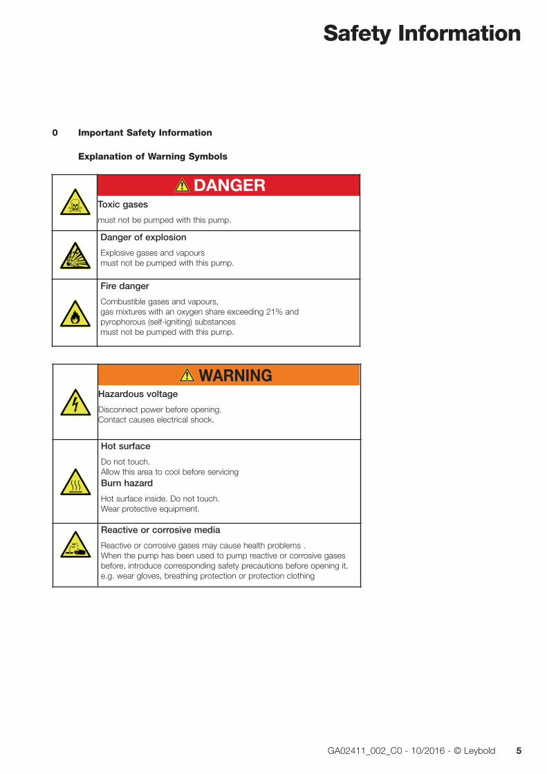
0 Important Safety Information
Explanation of Warning Symbols
Hazardous voltage
Disconnect power before opening.Contact causes electrical shock.
Hot surface
Do not touch.Allow this area to cool before servicingBurn hazard
Hot surface inside. Do not touch.Wear protective equipment.
Reactive or corrosive media
Reactive or corrosive gases may cause health problems . When the pump has been used to pump reactive or corrosive gases before, introduce corresponding safety precautions before opening it, e.g. wear gloves, breathing protection or protection clothing
Toxic gases
must not be pumped with this pump.
Danger of explosion
Explosive gases and vapours must not be pumped with this pump.
Fire danger
Combustible gases and vapours, gas mixtures with an oxygen share exceeding 21% and pyrophorous (self-igniting) substances must not be pumped with this pump.

Safety Information
6 GA02411_002_C0 - 10/2016 - © Leybold
Purge gasCheck compatibility with applications. Overpressure in the discharge lineComponents can be thrown in all directions.The pressure in the discharge line must not exceed atmospheric pressure by 200 mbar max.The discharge line must not be blocked or restricted
Pumps with wheels
must only be placed and moved on levelled horizontal surfaces!
Rotating parts
When operating the pump with open intake port, there is the risk of suffering injury by rotating parts.Never operate the pump with open intake port or fan cover, except from checking the direction of rotation.
Vacuum
Avoid exposing any part of the human body to the vacuum.
Machinery starts automatically
Connect the pump so that it not will restart automatically after a mains power failure, once the power returns.
Overhead load
Transport the pump only at the crane eye or with a forklift secured on a suitable palette.

Safety Information
7GA02411_002_C0 - 10/2016 - © Leybold
0.1 Mechanical Hazards1 When operated with an open intake flange, there exists a risk of suffer-
ing injury by rotating parts. Do not operate the pump with an open intake flange or fan cover except when checking the direction of rota-tion.
2 Avoid exposing any part of the human body to the vacuum.
3 The pump is intended for generating a vacuum only. If an overpressure can occur in the system then the pump must be protected against such an overpressure by an overpressure safety valve, for example.
4 We recommend to always operate the pump with a silencer or a con-nected discharge line. The pressure in the discharge line must not exceed atmospheric pressure by 200 mbar max.
Make sure that the gas flow at the discharge is not blocked or restrict-ed in any way, even when the pumped out gases need to be collected or contained.
The discharge line must not be blocked or restricted. Before commis-sioning the pump, open all shutoff devices or valves in the discharge line.
In the case of processes involving much condensate, we recommend the installation of a condensate separator in the discharge line.
5 Select the location where the pump is installed so that all controls can be easily accessed. Deposit the pump only on a floor which is level. It can topple when it is tilted by more than 10° with respect to the verti-cal axis. When the pump is filled with oil an angle exceeding 2° is not permissible.
For pumps on castors only Because of the fitted castors, the pump must only be placed on a level floor capable of supporting the pump’s weight, as otherwise there exists the risk of the pump rolling away. Moreover, the pump may only be moved on a level floor! Moving the pump along sloping paths or ramps is prohibited! The pump must only be transported with a forklift or a crane! At the installation location, secure against rolling away.
6 For transporting the pump use only approved transport means. When selecting the lifting and transport means take note of the total weight before transporting the pump. As standard, the pump has been equipped with a crane eye. When transporting the pump with a forklift or alike, ensure that the pump has been secured on the supplied or a suitable palette. The crane eye of the screw pump must never be used to lift any pump combinations (Roots pump + backing pump).
CAUTION

Safety Information
8 GA02411_002_C0 - 10/2016 - © Leybold
7 Before beginning with any maintenance and servicing work always ensure that no gas can flow backwards through the pump since then the rotors might turn against the normal direction of rotation. For this reason vent the vacuum chamber to the exhaust pressure level or ensure through suitable valves that the vacuum chamber and the lines are reliably separated from the pump. When connecting several pump systems, pressure differences between inlet and discharge can give rise to uncontrolled turning of the pump’s shafts.
8 Lay electric feed and cooling water lines so that there is no risk of tripping over these.
9 Maximum cooling water pressure: 10 bar. When exceeded, there is the risk of leaks.
10 The warning information on the pump must not be covered.
11 When changing the oil remove any escaped oil as otherwise there is the risk of slipping.
0.2 Electrical Hazards1 The electrical connection must only be provided by a trained person.
Please observe the national regulations in the country of use like EN 50110-1 for Europe, for example.
2 Lay the connecting lines so that they cannot be damaged. Protect the lines against humidity and contact with water. Avoid thermally stressing the lines due to unfavourable laying.
3 Note the information on the type of protection.
4 The pump must only be operated at the frequency specified for the motor even when operated off a frequency converter. When using frequency converters you must ensure an effective protec-tion against overspeeding.
5 Always operate the pump with a properly connected protective earth conductor.
6 The pump must be integrated within the system controller such that the pump can not run up automatically when the pump has been shut down before due to an overloaded motor. This equally applies to any emergency shutdowns. After having removed the fault cause, the pump must be switched on manually again.
7 Before starting with any maintenance or servicing work reliably discon-nect the pump from all sources of power (lockout/tagout).
8 High electric voltages! When touching parts at high electric voltages, there is the risk of suffering severe injuries by an electric shock! Covers marked with this symbol must only be opened by trained electricians after having reliably deenergised (lockout/tagout) the equipment.
9 Observe the manufacturer’s information and the Operating Instructions for the respective frequency converter.
DANGER

Safety Information
9GA02411_002_C0 - 10/2016 - © Leybold
10 After having connected the motor and each time after having made changes to the wiring, check the direction of rotation. If the direction of rotation is wrong, the pressure can increase on the intake side. Moreover, the pump can suffer damage.
0.3 Thermal Hazards1 With the pump warm from operation, the housing and oil temperature
may exceed 70 °C. Protect hot parts against being touched. Let pump and oil cool down. Always wear protective gloves and protective gog-gles, also for protection against aggressive residues in the oil.
2 Handle the pump only while vented and after having let it cool down.
3 Take note of the warning information on the housing surface. If this warning information was removed, covered or obstructed, then pro-vide corresponding additional warning information.
4 For the water cooled versions: Before disassembling any cooling water lines, leave the pump to cool down, shut off the feed line.
When uninstalling the cooling water lines, take note of splashing water. Heated water can cause burns.
5 Never open the oil fill or oil drain plugs while the pump is running. There is the risk of suffering burns.
0.4 Hazards Caused by Materials and Substances1 The pump is not suited for pumping of:
■ combustible and explosive gases and vapours (except within the permissible scope for pumps certified in accordance with ATEX Category 3 inside) ■ radioactive and toxic substances ■ gas mixtures with an oxygen share exceeding 21% ■ pyrophorous (self-igniting) substances.
Moreover, the pumps are not suited for placement and operation within explosion hazard areas.
Please consult us first when planning such an application.
2 Before commissioning the pump, make sure that the media which are to be pumped are compatible with each other so as to avoid hazard-ous situations. All relevant safety standards and regulations must be observed.
3 Before operating the pump with a gas ballast or a purge gas (option) check the compatibility of the gas with the pumped media so as to avoid dangerous conditions during operation.
4 Pump with installed purge gas unit: When operating the pump with a purge gas valve, secure the purge gas supply so that in the event of a malfunction no overpressure can occur in the system.
CAUTION
DANGER
Safety Information
10 GA02411_002_C0 - 10/2016 - © Leybold
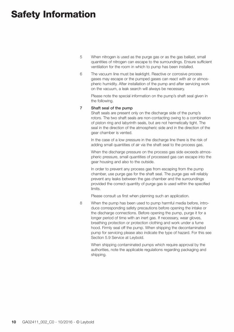
5 When nitrogen is used as the purge gas or as the gas ballast, small quantities of nitrogen can escape to the surroundings. Ensure sufficient ventilation for the room in which to pump has been installed.
6 The vacuum line must be leaktight. Reactive or corrosive process gases may escape or the pumped gases can react with air or atmos-pheric humidity. After installation of the pump and after servicing work on the vacuum, a leak search will always be necessary.
Please note the special information on the pump’s shaft seal given in the following.
7 Shaft seal of the pump Shaft seals are present only on the discharge side of the pump’s rotors. The two shaft seals are non-contacting owing to a combination of piston ring and labyrinth seals, but are not hermetically tight. The seal in the direction of the atmospheric side and in the direction of the gear chamber is vented.
In the case of a low pressure in the discharge line there is the risk of adding small quantities of air via the shaft seal to the process gas.
When the discharge pressure on the process gas side exceeds atmos-pheric pressure, small quantities of processed gas can escape into the gear housing and also to the outside.
In order to prevent any process gas from escaping from the pump chamber, use purge gas for the shaft seal. The purge gas will reliably prevent any leaks between the gas chamber and the surroundings provided the correct quantity of purge gas is used within the specified limits.
Please consult us first when planning such an application.
8 When the pump has been used to pump harmful media before, intro-duce corresponding safety precautions before opening the intake or the discharge connections. Before opening the pump, purge it for a longer period of time with an inert gas. If necessary, wear gloves, breathing protection or protection clothing and work under a fume hood. Firmly seal off the pump. When shipping the decontaminated pump for servicing please also indicate the type of hazard. For this see Section 5.9 Service at Leybold.
When shipping contaminated pumps which require approval by the authorities, note the applicable regulations regarding packaging and shipping.
Safety Information
11GA02411_002_C0 - 10/2016 - © Leybold
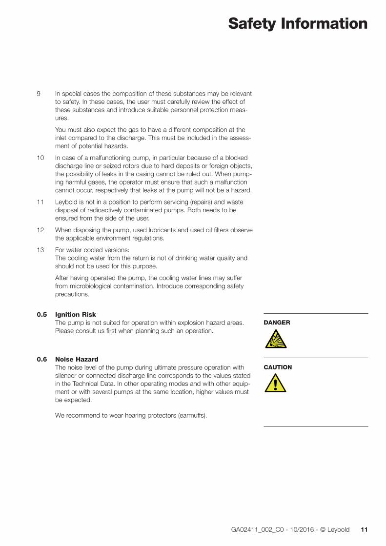
9 In special cases the composition of these substances may be relevant to safety. In these cases, the user must carefully review the effect of these substances and introduce suitable personnel protection meas-ures.
You must also expect the gas to have a different composition at the inlet compared to the discharge. This must be included in the assess-ment of potential hazards.
10 In case of a malfunctioning pump, in particular because of a blocked discharge line or seized rotors due to hard deposits or foreign objects, the possibility of leaks in the casing cannot be ruled out. When pump-ing harmful gases, the operator must ensure that such a malfunction cannot occur, respectively that leaks at the pump will not be a hazard.
11 Leybold is not in a position to perform servicing (repairs) and waste disposal of radioactively contaminated pumps. Both needs to be ensured from the side of the user.
12 When disposing the pump, used lubricants and used oil filters observe the applicable environment regulations.
13 For water cooled versions: The cooling water from the return is not of drinking water quality and should not be used for this purpose.
After having operated the pump, the cooling water lines may suffer from microbiological contamination. Introduce corresponding safety precautions.
0.5 Ignition RiskThe pump is not suited for operation within explosion hazard areas. Please consult us first when planning such an operation.
0.6 Noise HazardThe noise level of the pump during ultimate pressure operation with silencer or connected discharge line corresponds to the values stated in the Technical Data. In other operating modes and with other equip-ment or with several pumps at the same location, higher values must be expected.
We recommend to wear hearing protectors (earmuffs).
DANGER
CAUTION

Safety Information
12 GA02411_002_C0 - 10/2016 - © Leybold
0.7 Risk of Pump Damage1 With the pump filled with oil it must placed such that it will deviate by
no more than 2° from the vertical axis as otherwise oil can enter into the sealing system. Before filling the pump with oil, align it. Transporting the pump filled with oil is not permissible.
2 Always use the intake screen which has been fitted as standard and clean it regularly. The intake screen serves to protect the pump. Small items (screws, welding beads, pieces of wire, etc.) which during instal-lation work inadvertently fall into the intake line or are sucked in, are retained by the intake screen.
The intake screen does not replace a filter. Prevent the intake of parti-cles from the side of the process by fitting suitable filters. Upstream fil-ters protect the pump against damage to the pump chamber.
3 When pumping dust containing media, install a dust filter in the pro-cess gas flow upstream with respect to the pump.
4 When connecting the pump, provide a suitable valve on the intake side for the purpose of shutting off the intake line so as to prevent the pump from turning backwards in the event of a power failure. Otherwise the pump may suffer damage or oil may contaminate the pump chamber by reverse venting via the shaft seals.
5 Lines and other vacuum connections should be clean and free of oil. Special attention must be paid here when oil-sealed pumps have been used on the vacuum side. Check the conditions before initial commis-sioning. In the case of deviations, the pump can suffer contamination with oil residues.
6 The pressure within a pump which has been switched off will increase to ambient pressure within a few seconds. In such a case the pump is vented through the discharge and the shaft seal drain. We recommend to fit a nonreturn discharge valve so as to prevent the pump from turn-ing backwards.
7 The discharge line should be laid so that it slopes down and away from the pump so as to prevent condensed vapours from backstream-ing into the pump.
8 In the case of wet processes we recommend the installation of liquid separators, upstream and downstream of the pump so as to avoid the influx of liquid into the pump.
9 During installation work on the intake and discharge lines do not sub-ject flanges to any stresses. Check the rubber elements of the pump’s feet as to any deformation.
10 Protect the electric motor against being overloaded: For proper connection, a suitable motor protection switch must be used. Set this motor protection switch in agreement with the informa-tion provided on the motor nameplate. Connect the pump to the correct mains voltage and mains frequency.
NOTICE

Safety Information
13GA02411_002_C0 - 10/2016 - © Leybold
11 The pump’s motor is equipped with an overtemperature protection (PTC). Processing the PTC signal is a safety measure which in the case of inadequate cooling, a temporary mains power phase failure or in the case of frequency variations offers effective protection preventing costly damage to the motor coils.
12 The pump must only be operated with all covers in place so that ade-quate cooling of the pump is ensured.
13 If corrosive or reactive gases at low concentrations are being pumped, then operate the pump with purge gas. Consult us first as to which pumps are required for specific processes and applications.
14 Before pumping condensable vapours the pump should be at ope-rating temperature. If a gas ballast is present, then it should be opened. The pump will attain its operating temperature approximately 30 minutes after having started the pump. During this warm-up phase, the pump should be left separated from the process by a valve in the intake line, for example.
15 With the pump warm from operation do not clean it from the outside with water. There is the risk of a rotor crash due to shock cooling.
16 If condensable vapours have been pumped, the pump should before switching off be purged with an inert gas or air (depending on the spe-cific application) for approximately 15 minutes. This process should also be run before cleaning the pump chamber.
17 For shutting down the pump purge the pump before switching off with an inert gas or air (depending on the specific application) for approxi-mately 15 minutes. Place desiccant onto the intake screen in the intake flange and into the discharge flange and blank off the flanges with a piece of foil. Disconnect the pump from the mains power. When storing the pump for a longer period of time, drain out the oil first. Package the pump airtight in polyethylene foil.
18 Improper maintenance or repair work can have an influence on the service life and the performance of the pump and will void any warran-ty claims.
19 For water cooled versions: Failure to comply with the cooling water data may lead to internal cor-rosion. This will result in damaging the pump.
20 If you transport/store or air-ship a water cooled pump and if there is at the same time the risk of frost, the water may freeze and damage the pump. For this reason before transporting the pump or storing it, drain out the water. For this refer to Section 4.3 Shutting Down.
Pressures given in bar or mbar are absolute values. If exceptionally a gauge pressure is meant, a “g” is added (bar(g) = bar (gauge) = bar overpressure)
ATEX
14 GA02411_002_C0 - 10/2016 - © Leybold
SP 630 / SP 630 F ATEX Category 3 (inside) Vacuum Pump
Classification and Marking of the PumpThe SP 630 ATEX Category 3 (inside) fulfils for the inside, i.e. the process gas side of the pump, the fundamental safety requirements of the EC Directive 2014/34/EU. The pump is marked as follows:
II (inside) 3GD II T160 °C X (10 °C < Ta < 40 °C)
These pumps are not suited for placement (installation) in explosion hazard areas.
Key to the SymbolsII Equipment group II applies to all equipment in areas which are potentially
endangered by an atmosphere capable of exploding, except in under-ground mining operations and their above ground facilities which may be endangered by mine gas and/or combustible types of dust.
(inside)/(outside) Specifies the category/conditions according to which the inside (i) (i.e. parts of the equipment in contact with the process gas flow) and the out-side (o) of the equipment are classified, provided there is a difference between them.
3 Category 3 comprises equipment which is so designed that it can be oper-ated in agreement with the characteristic quantities (operating parameters) specified by the manufacturer ensuring a normal degree of protection. Equipment belonging to this category is intended for operation in areas where it not needs to be expected that an explosive atmosphere occurs due to gases, vapours, mists or raising dust, but when it occurs, then with all probability only rarely and briefly. Equipment belonging to this category ensures during normal operation the necessary degree of safety.
G For areas with an atmosphere capable of exploding caused by gases, vapours or mists in the air.
D For areas with an atmosphere capable of exploding caused by explosive dusts.
For Part Numbers 117 017 - 117 019 117 115, 117 116

ATEX
15GA02411_002_C0 - 10/2016 - © Leybold
The pump is not suited for utilisation in dusty areas.
II, IIA, IIB or IIC Explosion groups: these are subdivisions for equipment belonging to Group
II, which are used in connection with some protection types. This subdivision is based on the maximum experimental safe gap and the minimum ignition current of the explosive atmosphere. See EN 60079-0.
Equipment marked with IIB is also suited for applications which require equipment marked with IIA. Correspondingly, equipment marked with IIC is also suited for applications which require equipment belonging to explosion group IIA or IIB. Equipment which is suited for all applications can be marked by II or is not marked at all.
Equipment without marking of the explosion group is suited for applica-tions in explosive atmospheres of explosion groups IIA, IIB, IIC.
T3, T4 Temperature class: classification of equipment within classes depending on their maximum surface temperature corresponding to the table given below:
Temperature class Maximum surface temperature (°C)
T1 450
T2 300
T3 200
T3 (160 °C) 160
T4 135
T5 100
T6 85
The temperature class and the actual maximum surface temperature of the equipment includes a safety margin with respect to the minimum ignition temperature of the potentially explosive atmosphere as demanded by EN 13463-1.
Ta Permissible ambient temperature for operating the pump 10 °C < Ta < 40 °C.
X Special operating conditions need to be complied with! The special conditions and information provided in the Operating Instructions apply.
Modifying the supplied pump, voids the CE and ATEX Declaration of Conformity.
Related Accessories When using accessory components together with the pump it needs to be ensured that these accessories are suited for operation in explosion hazard areas.
ATEX
16 GA02411_002_C0 - 10/2016 - © Leybold
Operation in a Pump SystemJoint operation of the SP 630 Cat 3 (inside) and a directly flanged on Roots WAU 2001 Cat 3 (inside) in a pump system is possible. The resulting tem-perature class results from the respective usage parameters of the Roots WAU 2001, may, however, not be lower then the temperature class of the Roots pump.
For other combinations, an assessment of the ignition risk for the pump sys-tem must be performed
Areas of ApplicationThe inside (process gas side) of this vacuum pump is so rated and designed that the occurrence of foreseeable ignition sources can be excluded during normal operation. Provided the pump is operated in accordance with the parameters specified in the Operating Instructions the pump will offer a nor-mal degree of protection. For this reason it is suited for operation under con-ditions where it is unlikely that an atmosphere capable of exploding is created by gases, dusts, vapours or mists in the air or if such atmospheres do occur then this only rarely and only briefly (i.e. Zone 2).
The pump itself must not be installed and operated in explosion hazard areas.
Areas in which explosive atmospheres (gases, dusts, vapours or mists) can occur in the air are subdivided into three zones corresponding to the frequen-cy and duration of occurrence of an explosive atmosphere. These zones are designated as 0, 1 and 2.
The definitions for these zones are described in Annex I of the “ATEX Directive (Directive 99/92/EG) for improving the safety and health protection of workers potentially at risk from explosive atmospheres”.
Information as to the classification of the areas with explosive atmospheres in the 3 Zones, is provided in the Directive 99/92/EG and the corresponding guide (COM (2003) 515) together with the European standard EN 60079-10 (Electrical apparatus for explosive gas atmospheres - Part 10: Classification of hazardous areas). Additionally, further information on the avoidance of explosions and on the topic of explosion protection can be found in the Directive 99/92/EG and the corresponding guide.
This information can be downloaded from the EC internet site.
Gas CompositionIt is important to note that the composition of the gas at the intake on the suction side of the pump and at the exhaust to the atmosphere may possibly differ. This may possibly have an influence on the zone assignments (EG Directive 99/92/EG).
DANGER
ATEX
17GA02411_002_C0 - 10/2016 - © Leybold
Ignition Temperatures of Gases/VapoursThe pumps are suited only for applications in which potentially explosive gas and vapour mixtures exhibit an ignition temperature of over 160 °C.
The ignition temperatures (sometimes also called self ignition temperature) of gases and vapours can be taken from the Material Safety Data Sheets (MSDS).
The pump is not suited for operation in potentially explosive gas mixtures in which the oxygen concentration exceeds 21% or if reactive, aggressive or corrosive gases are present.
Ignition Temperatures of DustsAccording to directive 99/92/EG the system operator is committed to run a hazards assessment. For this reason the minimum glow point temperature and the minimum ignition temperature of the dust must be known.
Two calculations for determining two limit temperatures must be performed:
a) Limit temperature 1 = 2/3 of the minimum ignition temperature
b) Limit temperature 2 = minimum glow point temperature* less 75 K
From these two calculated limit temperatures it will now be necessary to take into account the value which guarantees the higher degree of safety.
*The value for the glow temperature applies to a dust thickness of 5 mm. In the case of even thicker dust deposits, the temperature safety margin should be increased even further.
Potential Ignition SourcesAn assessment of the ignition risk was performed in accordance with the European standard EN 13463-1 (EN 13463-1 Non-electrical equipment for potentially explosive atmospheres. Part 1: Basic method and requirements). Based on this assessment the ignition sources listed in the following were determined which may occur during operation of the pump:
Potential ignition sources Remarks
Hot surfaces inside and outside due to process gas inlet temperature and gas compression
Hot gases, adiabatic Hot gases from the process which are being compression pumped, temperature increase owing to gas compression within the pump. Hot gases are ejected at the exhaust.
Mechanical sparks Will not occur during normal operation
Electrical sparks Outside of the pump due to motor, accessories
Static electricity Will not occur during normal operation
Chemical reactions Will not occur during normal operation

ATEX
18 GA02411_002_C0 - 10/2016 - © Leybold
Special Requirements for Safe Usage “X” Conforming utilisation of this pump demands the connection of, and oper-
ation with purge gas for Category 3 (inside).
For particle, respectively dust filters, the use of a mesh of 40 µm max. will be mandatory in connection with ATEX applications so as to ensure the safe operation.
If dusts occur, then an approved dust filter must be used and must be electrically connected to ground correspondingly.
The pump must exclusively be filled and operated with the oil LVO 210 as the operating agent.
The use of any other kind of oil may result in increased surface tempera-tures and cause severe damage to the pump.
During normal operation, the oil temperature must not exceed 80° C when air cooled, and 60 °C when water cooled. A regular check will be neces-sary, see also Section 3.5 Oil Temperature.
The pump must be installed such that oil sight glass and SP-Guard are easily visible and cannot be damaged. The oil level must be checked regu-larly.
The pump must be installed so that only minimal quantities of dust can deposit themselves on the surfaces. In those cases where dust deposits form, measures must be introduced to remove these a regular basis.
The pumps must only be operated at an ambient temperature ranging between 10 °C and 40 °C.
The maximum gas admission temperature must not exceed 100 °C.
The maximum overpressure at the gas inlet must not exceed pamb + 55 mbar.
The maximum exhaust back pressure must not exceed pamb + 200 mbar.
Safety Measures
Hot SurfacesCompression of the gases will during normal operation of the vacuum pump cause it to heat up resulting in hot surfaces. Tests have shown that during conforming operation of the pump (in accordance with these Operating Instructions) the process gas path which might come into contact with a potentially explosive atmosphere, attains during operation at a nominal fre-quency of 50 Hz or 60 Hz a maximum temperature below 160 °C.
The maximum temperatures are attained during constant operation at an inlet pressure below 300 mbar (absolute). The actually attained temperature depends on the inlet pressure.
Higher maximum surface temperatures can occur when not filling and oper-ating the pump with the oil LVO 210.
ATEX
19GA02411_002_C0 - 10/2016 - © Leybold
Hot GasesDue to compression of the gases, the pump will produce during normal oper-ation hot exhaust gases. The exhaust gas temperatures will not exceed the stated maximum surface temperatures of the pump. The exhaust gases need to be discharged through a suitable exhaust gas system.
Mechanical SparksDuring normal operation no mechanically generated sparks are created.
The intake of particles into the pump must be prevented so as to prevent the formation of hot spots due to friction.
Electric SparksThese can be caused by the electric motor and the accessories supplied with the pump. Where the outside of the pump has been certified then motor and supplied accessories have the same classification. Follow the manufac-turer’s information.
Static ElectricityThe pump needs to be sufficiently grounded so as to avoid any electrostatic charging. This is attained when the ground connection is properly connected at the point provided for this purpose. During normal operation no dangerous electrical charges will be produced (for further information relating to the haz-ards caused by static electricity, see CENELEC report CLC/TR 50404: 2003 Electrostatics - Code of practice for the avoidance of hazards due to static electricity).
In connection with ATEX usage, the electrically conducting link between pump chamber cover, exhaust flange and gear housing is absolutely manda-tory! After any assembly work on the pump chamber, this link must be checked. For this, use a resistance meter and measure the resistance of the link which must be less than 100 Ohm.
A filter on the intake side must be connected to ground in accordance with the Operating Instructions of the filter.
Use only the original spare parts from Leybold.
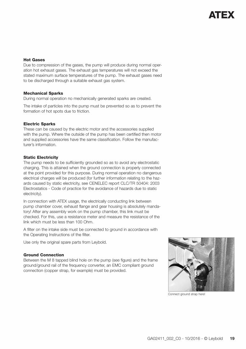
Ground ConnectionBetween the M 8 tapped blind hole on the pump (see figure) and the frame ground/ground rail of the frequency converter, an EMC compliant ground connection (copper strap, for example) must be provided.
Connect ground strap here!

ATEX
20 GA02411_002_C0 - 10/2016 - © Leybold
Chemical ReactionsThe pump shall not come in to contact and shall not be used in connection with reactive or corrosive gases which may cause an exothermal chemical reaction.
Additional Safety MeasuresOverheating of the pump can give rise to temperatures which exceed the certified maximum surface temperature.
Compliance with the operating parameters stated in these Operating Instructions must be ensured.
Run checks on a regular basis and comply with the maintenance schedule.
Additional Maintenance RequirementsIn those cases where dust may deposit itself on the pump or the motor sur-faces, measures must be introduced which ensure that such deposits are removed on a regular basis.
In order to ensure that the defined level of safety is maintained, only accesso-ry parts and wearing parts from Leybold must be used.
Description
21GA02411_002_C0 - 10/2016 - © Leybold
1 Description
1.1 Design and FunctionThe SP 630 is a dry compressing screw-type vacuum pump capable of a maximum pumping speed of 630 m3 · h-1.
It has been developed specifically for the special requirements of industrial applications. Thus the ruggedness of the pump was a main design criterion.
The screw shaped rotors are fitted to two horizontally arranged shafts and revolve without making contact within the pump chamber. The shafts are synchronised by a toothed gear. The shafts are driven via a further gear stage by an electric motor.
In vacuum pumps, the seals and the bearings on the vacuum side are always a potential source for a breakdown. On the one hand lubricants may enter from the bearing into the vacuum process and on the other hand aggressive process media can endanger the bearings.
These disadvantages are avoided by the “cantilevered” arrangement of the rotors. The SP 630 is equipped with two cantilevered screw type rotors which are guided by oversized shafts and bearings. The bearings are located both in the gear chamber of the pump.
A further advantage of the cantilevered arrangement is that the pump cham-ber is easily accessible without having to disassemble any bearings. Thus any possibly required cleaning operations necessary due to the influence of the process can be run easily.
The cantilevered rotors minimise the risk of bearing damage and also reduce on-site maintenance to a minimum.
Shaft seals are in the case of the SP 630 pump only required on the delivery side of the rotors. Owing to the small pressure difference between discharge and gear, simple and reliable seals can be provided. The two shaft seals con-sist of a combination of a piston ring and a labyrinth seal thus making almost no contact so that the seals will be almost free of wear.
In standard applications no purge gas will be required at the seals. However, if demanded by the process conditions, a purge gas may be supplied to the seals. In the case of ATEX applications operation with purge gas is an absolute requirement.
The SP 630 is air-cooled, the SP 630 F is water-cooled. A radial fan supports the cooling effect for the casing which is equipped liberally with cooling fins.
Depending on requirements, the screw pumps may be combined with Roots pumps so as to attain higher pumping speeds at lower pressures.
Screw rotors
Cantilevered bearing
Shaft seal
Purge gas
Cooling

Description
22 GA02411_002_C0 - 10/2016 - © Leybold
Fig. 1.1 Principle of operation of a screw pump
Fig. 1.2 Compression principle and the direction of pumping action within a screw pump
Casing
Intake side
Rotors (screws)
Direction of flow
Discharge side
Direction of rotation of the shafts
Fig. 1.3 pV diagrams of screw pumps
(a) (b) (c)
without inner compression with inner compression against the face side of the pump chamber
with inner compression along the rotor (SCREWLINE)
Description
23GA02411_002_C0 - 10/2016 - © Leybold
SP 630 F - Water CooledThe areas of application for the SP 630 F are smaller and air-conditioned rooms so as to not unnecessarily heat up the ambient air.
The water cooled pump is also used under ambient conditions which involve much contamination since here at a rapid contamination of the air heat exchanger must be expected.
The SP 630 F is equipped with a water cooled heat exchanger to cool the oil.
Principle of OperationIn the screw vacuum pumps of the SP 630 line the pump chamber is formed by two synchronised displacing rotors and the casing.
A pair of tightly intermeshing right-handed and left-handed threads is used to implement with only very few components a large number of stages and thus very low ultimate pressures.
Figures 1.1 and 1.2 show how by the two rotors and the housing several chambers are created which allow the gas to be compressed. Since the rotors turn in opposing directions, the chambers “move” steadily from the intake to the delivery side of the pump (Fig. 1.2) so that the gas is conveyed in a low-pulsation manner.
The continuous pumping action for the gas without the need of having to deflect the gas will also allow pumping of particles entrained in the gas and also vapours to a limited extent.
As in the case of other dry compressing (slot sealed) vacuum pumps, also in the case of screw pumps very tight slots need to be maintained between the components. Otherwise the leaks caused by the pressure drop would have a negative effect on both pumping speed and attainable ultimate pressure. Moreover, the pump might heat itself up too much due to unfavourable ther-modynamic processes.
During operation the design of the SP 630 ensures that the slots are main-tained within the operational limits of the pump. In order to limit the tempera-tures attained by the components, the housing of the pump chamber is air-cooled. Also the rotors themselves are cooled: by oil which is pumped through bores in the rotor shafts and which also lubricates the bearings and the toothed wheels of the pump’s synchronising gear. Thus an even tempera-ture spread is attained within the pump.
The amount of “inner compression” has a significant influence on the tem-perature level within a vacuum pump. In the case of a foreline pump, most of the work on compression is done while the gas is being ejected against the delivery pressure, i.e. in the last stages of the pump. For this reason in the case of the SP 630 the volume of the gas is already significantly reduced at pressures which are as low as possible so as to minimise this work done on compression. In this way the power requirement of the pump is reduced and less heat needs to be dissipated.
Gas compression
Slots
Description
24 GA02411_002_C0 - 10/2016 - © Leybold
Fig. 1.3 shows the pV diagram of screw pumps: (a) without inner compres-sion, (b) with inner compression against the face side of the pump chamber and (c) by reducing the chamber volume along the rotor. The surface areas enclosed in the pV diagram are in each case proportional to the power uptake of the pump. It is apparent that the most efficient method is to com-press the gas which is to be pumped by reducing the axial pitch of the rotor from the inlet to the delivery side (fig. 1.2) so that the chamber volume is already reduced at low pressures (fig. 1.3c). In this way a power consumption can be attained which is comparable to that of rotary vane pumps.
pV diagram for screw pumps
Description
25GA02411_002_C0 - 10/2016 - © Leybold
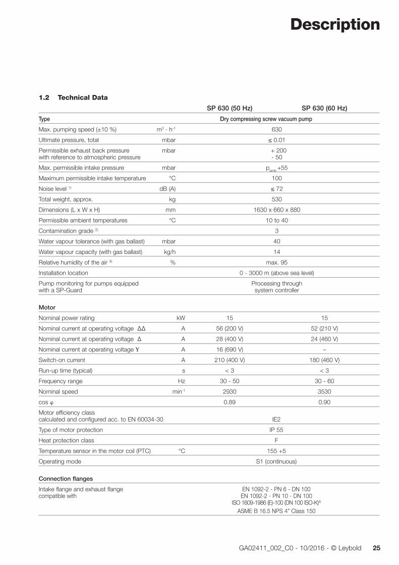
1.2 Technical Data
SP 630 (50 Hz) SP 630 (60 Hz)
Type Dry compressing screw vacuum pump
Max. pumping speed (±10 %) m3 · h-1 630
Ultimate pressure, total mbar ≤ 0.01
Permissible exhaust back pressure mbar + 200 with reference to atmospheric pressure - 50
Max. permissible intake pressure mbar pamb +55
Maximum permissible intake temperature °C 100
Noise level 1) dB (A) ≤ 72
Total weight, approx. kg 530
Dimensions (L x W x H) mm 1630 x 660 x 880
Permissible ambient temperatures °C 10 to 40
Contamination grade 2) 3
Water vapour tolerance (with gas ballast) mbar 40
Water vapour capacity (with gas ballast) kg/h 14
Relative humidity of the air 3) % max. 95
Installation location 0 - 3000 m (above sea level)
Pump monitoring for pumps equipped Processing through with a SP-Guard system controller
Motor
Nominal power rating kW 15 15
Nominal current at operating voltage ∆∆ A 56 (200 V) 52 (210 V)
Nominal current at operating voltage ∆ A 28 (400 V) 24 (460 V)
Nominal current at operating voltage Υ A 16 (690 V) –
Switch-on current A 210 (400 V) 180 (460 V)
Run-up time (typical) s < 3 < 3
Frequency range Hz 30 - 50 30 - 60
Nominal speed min-1 2930 3530
cos 0.89 0.90
Motor efficiency class calculated and configured acc. to EN 60034-30 IE2
Type of motor protection IP 55
Heat protection class F
Temperature sensor in the motor coil (PTC) °C 155 +5
Operating mode S1 (continuous)
Connection flanges
Intake flange and exhaust flange EN 1092-2 - PN 6 - DN 100 compatible with EN 1092-2 - PN 10 - DN 100 ISO 1609-1986 (E)-100 (DN 100 ISO-K)4) ASME B 16.5 NPS 4” Class 150

Description
26 GA02411_002_C0 - 10/2016 - © Leybold
Technical Data (continued)
Operating agents
Cooling Air Water Cooling water temperature 5 - 35 °C
Approved type of oil: LVO 210 l 15
Materials Aluminium, aluminium (in contact with the gas) anodic coating, C steel, CrNi steel, grey cast iron, FPM
1) at ultimate pressure with connected discharge line without silencer, in accordance with ISO 4871(acc. to DIN EN ISO 2151), KpA=3dB2) in accordance with EN 50178 3) in accordance with EN 60721-3-3 4) this collar flange is required, when ISO-K flanges are to be connected (P/N 267 50)
1.2.1 Technical Data for the Water Cooling System(for water cooled pumps only)
Water connection (2x) G 1/2”
Water supply temperature 5 °C - 35 °C
Maximum supply pressure (pmax) 10 bar
Minimum supply pressure (pmin) 2 bar
Nominal flow at a supply temperature of 25 °C 12 l/minute
Cooling air/water (approx. 50 %/50 %)1) (at a supply temperature of 5 to 25 °C ) (approx. 70 %/30 %)1) (at a supply temperature of 25 to 35 °C)
1) Applies to room temperatures of 20 - 25 °C
DD
D
R
W
E
Power in kW E R W D Totalat ultimate pressure 0.0 4.5 6.0 0.5 11.0for cyclic operation 2.5 5.0 7.0 0.5 15.0 R = air cooling (Radiator)E = exhaust (Exhaust)D = environment (Dissipation) W = cooling water (Water cooled)
Fig.1.4 Heat dissipation at the SP 630 F

Description
27GA02411_002_C0 - 10/2016 - © Leybold
Fig. 1.5 Pumping speed curve for the SP 630/SP 630 F at 50 and 60 Hz
Pressure mbar
0
100
200
300
400
500
600
700
800
Pum
ping
Spe
ed
m3/h
10-3 10-2 10-1 100 101 102 103
10-1 1 10 Torr 75010-210-3
400
cfm
50
100
Intake pressure
Pum
pin
g s
pee
d
> 900
a
a
1220
555
b2
h5
l4
l1
b b1
b3
b4
h
l
l5l6 a1
h1
h3
h2
h4
l2
l3
l7
Fig. 1.6 Dimensional drawing for the SP 630
= Marks for safe handling by a forklift
a a1 b b1 b2 b3 b4
mm > 500 > 300 555 470 276 380 439 in. > 19.69 > 11.81 21.85 18.05 10.87 14.96 17.28
h h1 h2 h3 h4 h6 l
mm 806 100 698 450 248 120 1220 in. 31.73 25.04 27.48 17.72 9.76 4.72 48.03
l1 l2 l3 l4 l5 l6 l7mm 1626 703 880 157 514 189 250 in. 64.02 27.68 34.65 6.18 20.24 7.44 9.84
h5 68 – 75 mm for standard pumps 120 – 135 mm for pumps on castors
Clearance for maintenance work
> 900
Description
28 GA02411_002_C0 - 10/2016 - © Leybold
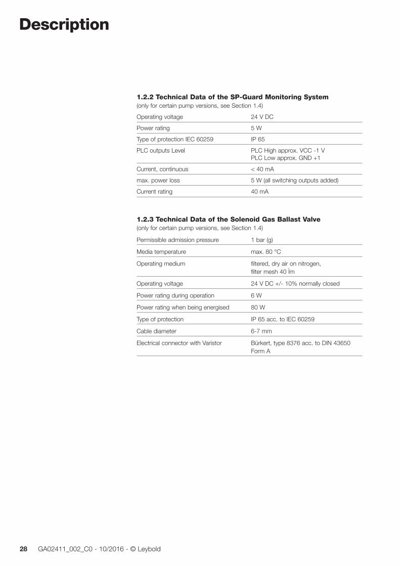
1.2.2 Technical Data of the SP-Guard Monitoring System(only for certain pump versions, see Section 1.4)
Operating voltage 24 V DC
Power rating 5 W
Type of protection IEC 60259 IP 65
PLC outputs Level PLC High approx. VCC -1 V PLC Low approx. GND +1
Current, continuous < 40 mA
max. power loss 5 W (all switching outputs added)
Current rating 40 mA
1.2.3 Technical Data of the Solenoid Gas Ballast Valve(only for certain pump versions, see Section 1.4)
Permissible admission pressure 1 bar (g)
Media temperature max. 80 °C
Operating medium filtered, dry air on nitrogen, filter mesh 40 Ìm
Operating voltage 24 V DC +/- 10% normally closed
Power rating during operation 6 W
Power rating when being energised 80 W
Type of protection IP 65 acc. to IEC 60259
Cable diameter 6-7 mm
Electrical connector with Varistor Bürkert, type 8376 acc. to DIN 43650 Form A
Description
29GA02411_002_C0 - 10/2016 - © Leybold
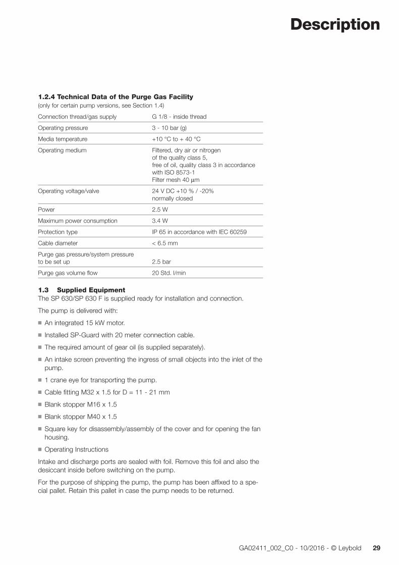
1.2.4 Technical Data of the Purge Gas Facility(only for certain pump versions, see Section 1.4)
Connection thread/gas supply G 1/8 - inside thread
Operating pressure 3 - 10 bar (g)
Media temperature +10 °C to + 40 °C
Operating medium Filtered, dry air or nitrogen of the quality class 5, free of oil, quality class 3 in accordance with ISO 8573-1 Filter mesh 40 µm
Operating voltage/valve 24 V DC +10 % / -20% normally closed
Power 2.5 W
Maximum power consumption 3.4 W
Protection type IP 65 in accordance with IEC 60259
Cable diameter < 6.5 mm
Purge gas pressure/system pressure to be set up 2.5 bar
Purge gas volume flow 20 Std. l/min
1.3 Supplied EquipmentThe SP 630/SP 630 F is supplied ready for installation and connection.
The pump is delivered with:
■ An integrated 15 kW motor.
■ Installed SP-Guard with 20 meter connection cable.
■ The required amount of gear oil (is supplied separately).
■ An intake screen preventing the ingress of small objects into the inlet of the pump.
■ 1 crane eye for transporting the pump.
■ Cable fitting M32 x 1.5 for D = 11 - 21 mm
■ Blank stopper M16 x 1.5
■ Blank stopper M40 x 1.5
■ Square key for disassembly/assembly of the cover and for opening the fan housing.
■ Operating Instructions
Intake and discharge ports are sealed with foil. Remove this foil and also the desiccant inside before switching on the pump.
For the purpose of shipping the pump, the pump has been affixed to a spe-cial pallet. Retain this pallet in case the pump needs to be returned.

Description
30 GA02411_002_C0 - 10/2016 - © Leybold
1.4 Built-in Accessories
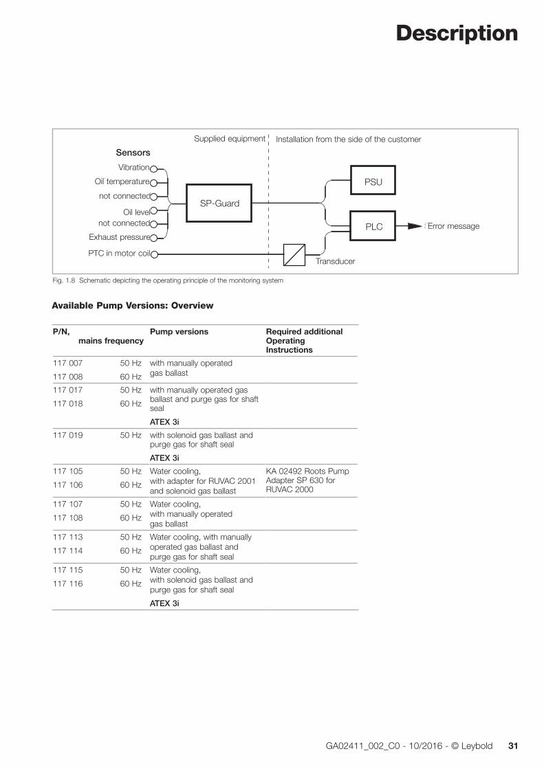
Monitoring System SP-GuardThe monitoring system SP-Guard monitors vibrations, oil temperature, oil level and exhaust pressure.
The output signals from the sensors are processed continuously by the SP-Guard. Should the SP-Guard detect an unsafe operating condition, then this is indicated through the error messaging output S2 to the connected system controller. This must cause an automatic shutdown of the pump pro-vided the signal from the SP-Guard is processed as intended. Moreover, a message is also indicated on the display.
The SP-Guard is capable of detecting at an early stage critical operating con-ditions, and outputs warning messages for oil temperature, gas temperature and vibration levels of the pump to the warning messaging output S1.
The user has thus the option of introducing early enough suitable measures like cleaning the oil cooler, for example, so as to ensure trouble-free operation of the pump.
Implemented within the SP-Guard is a pump operating hours counter. The number of operating hours can be indicated on the display.
Analogue inputs are available for acquiring vibration data and temperatures. The warning and shutdown thresholds regarding these measured quantities are configured in the factory.
The signal inputs for oil level and exhaust pressure are of the digital type. In the case of the sensor for the exhaust pressure, the signal must be present for 10 seconds at a pressure of over 1200 mbar.
The following outputs are available: S1 - Warning messaging output S2 - Error messaging output S3 - Watchdog S4 - Pump ON
When the shutdown thresholds are exceeded, the reason for the failure will be indicated on the display. After having checked the likely fault causes the SP-Guard may then be reset to the monitoring mode using the reset key.
The service technician has the option of reading the most recently saved measured values from the internal memory of the SP-Guard. This information will help to analyse the reasons for the specific failure.
Manually operated or solenoid gas ballast valveThe gas ballast valve is used for the purpose of avoiding condensation within the pump.
Purge gas facility(only for certain pump versions)
Purge gas prevents that process gas escapes via the two shaft seals to the environment and protects components and seals against corrosion.
SP-Guardvacuum
Fig. 1.7 SP-Guard
1
2
34
1 Display2 Key for display switchover and reset3 Connection for the sensor wire harness4 Connection for connection cable
Description
31GA02411_002_C0 - 10/2016 - © Leybold
Available Pump Versions: Overview
P/N, mains frequency
Pump versions Required additional Operating Instructions
117 007 50 Hz
117 008 60 Hz
with manually operated gas ballast
117 017 50 Hz
117 018 60 Hz
with manually operated gas ballast and purge gas for shaft seal
ATEX 3i
117 019 50 Hz with solenoid gas ballast and purge gas for shaft seal
ATEX 3i
117 105 50 Hz
117 106 60 Hz
Water cooling, with adapter for RUVAC 2001 and solenoid gas ballast
KA 02492 Roots Pump Adapter SP 630 for RUVAC 2000
117 107 50 Hz
117 108 60 Hz
Water cooling, with manually operated gas ballast
117 113 50 Hz
117 114 60 Hz
Water cooling, with manually operated gas ballast and purge gas for shaft seal
117 115 50 Hz
117 116 60 Hz
Water cooling, with solenoid gas ballast and purge gas for shaft seal
ATEX 3i
SP - Guard
Vibration
SPS
Sensoren
NetzteilÖltemperatur
Ölstand
Auslassdruck
nicht belegt
nicht belegt
PTC-MotorwicklungMesswandler
Störmeldung
Lieferumfang Kundenseitige Installation
Fig. 1.8 Schematic depicting the operating principle of the monitoring system
Sensors
Vibration
Oil temperature
Oil level
Exhaust pressure
not connected
PSU
PLC
SP-Guardnot connected
TransducerPTC in motor coil
Supplied equipment Installation from the side of the customer
Error message

Description
32 GA02411_002_C0 - 10/2016 - © Leybold
1.5 Accessories Part No.
Exhaust silencer with condensate drain 119 001
Serviceable silencer with condensate drain 119 004V
Non-return valve 119 010
Roots pump adapter for RUVAC 2001 119 021
Adapter disc for connection of a RUVAC WH(U) 2500 155222V required additionally: 119 021
Adapter disc for connection of a RUVAC WS(U) 1001 500003173 required additionally: 119 021
Roots pump Adapter for RUVAC WH(U) 4400 119 024V
Kit for retrofitting the manual gas ballast with a 24 V DC valve 119 054V
Dust filter (not suited for ATEX applications) 951 72
Adapter (universal flange DN 100 ISO-K) 119 020 (may be used to connect a dust filter, a valve or may be used universally)
Purge gas monitoring1) 119 014V
Flushing kit1) 119 015
Purge gas facility 119 030
Intermediate piece DN100 ISO-K 210 078
Fittings for silencing hood 119 006V0
Purge vent kit SP 630 119 060V
SECUVAC valve (not suited for ATEX applications) 24 V DC 215 225 100 - 115 V AC 215 226 200 - 230 V AC 215 227
Stability of the pump when using Leybold accessories is ensured. If other accessories are fitted then the user himself will be responsible for maintaining pump stability.
1) Only in connection with installed purge gas facility
Description
33GA02411_002_C0 - 10/2016 - © Leybold
1.6 Wearing Parts and Original Spare PartsUp to serial number 31000197911 Maintenance kit level 1, SP 630 for gear oil change, LVO 210, oil filter cartridge BG30 and two gaskets EK110000792
From serial number 31000197912 Maintenance kit level 1, SP 630 for gear oil change, LVO 210, oil filter cartridge BG60 and two gaskets EK110000832
Maintenance kit level 2, SP 630 for pump chamber inspection, 2 O-rings, intake screen including O-rings EK110000793
Maintenance kit level 3, SP 630 for axial bearing change, 2 O-rings, 6 gaskets (Cu), 2 angular ballbearings EK110000794
Replacement throttles for purge gas facility EK110000827
Additional spare parts are available from the Leybold service offices.
Transport and Storage
34 GA02411_002_C0 - 10/2016 - © Leybold
2 Transport and Storing
Please note safety information 0.1.5 and 0.1.6.
Before transporting the pump always drain the gear oil out.
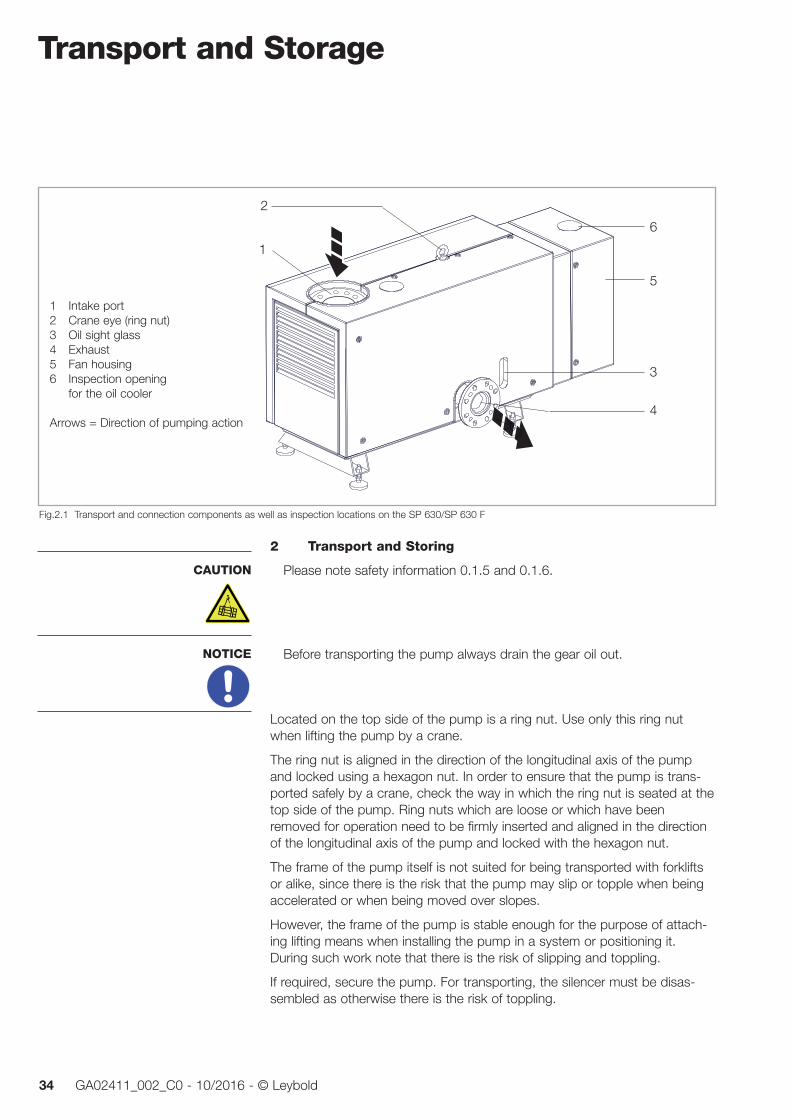
Located on the top side of the pump is a ring nut. Use only this ring nut when lifting the pump by a crane.
The ring nut is aligned in the direction of the longitudinal axis of the pump and locked using a hexagon nut. In order to ensure that the pump is trans-ported safely by a crane, check the way in which the ring nut is seated at the top side of the pump. Ring nuts which are loose or which have been removed for operation need to be firmly inserted and aligned in the direction of the longitudinal axis of the pump and locked with the hexagon nut.
The frame of the pump itself is not suited for being transported with forklifts or alike, since there is the risk that the pump may slip or topple when being accelerated or when being moved over slopes.
However, the frame of the pump is stable enough for the purpose of attach-ing lifting means when installing the pump in a system or positioning it. During such work note that there is the risk of slipping and toppling.
If required, secure the pump. For transporting, the silencer must be disas-sembled as otherwise there is the risk of toppling.
CAUTION
NOTICE
1 Intake port2 Crane eye (ring nut)3 Oil sight glass4 Exhaust5 Fan housing6 Inspection opening for the oil cooler
Arrows = Direction of pumping action
Fig.2.1 Transport and connection components as well as inspection locations on the SP 630/SP 630 F
2
3
4
5
6
1
Transport and Storage
35GA02411_002_C0 - 10/2016 - © Leybold
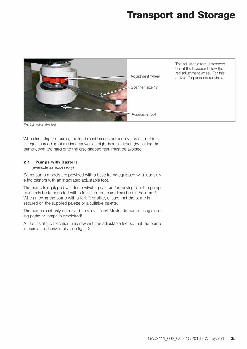
When installing the pump, the load must be spread equally across all 4 feet. Unequal spreading of the load as well as high dynamic loads (by setting the pump down too hard onto the disc-shaped feet) must be avoided.
2.1 Pumps with Castors (available as accessory)
Some pump models are provided with a base frame equipped with four swiv-elling castors with an integrated adjustable foot.
The pump is equipped with four swivelling castors for moving, but the pump must only be transported with a forklift or crane as described in Section 2. When moving the pump with a forklift or alike, ensure that the pump is secured on the supplied palette or a suitable palette.
The pump must only be moved on a level floor! Moving to pump along slop-ing paths or ramps is prohibited!
At the installation location unscrew with the adjustable feet so that the pump is maintained horizontally, see fig. 2.2.
Fig. 2.2 Adjustable feet
The adjustable foot is screwed out at the hexagon below the red adjustment wheel. For this a size 17 spanner is required.
Adjustable foot
Adjustment wheel
Spanner, size 17

Transport and Storage
36 GA02411_002_C0 - 10/2016 - © Leybold
2.2 Storing the PumpBefore putting the pump into storage, purge the pump before switching off with an inert gas or air (depending on the specific application) for approxi-mately 15 minutes.
Place a bag with desiccant in the discharge flange and onto the intake screen in the inlet flange, and seal off the flanges with foil. Do not place the desiccant, without the intake screen, directly into the inlet flange.
When shelving the pump for prolonged periods, drain out of the oil from the pump.
Package in the pump air-tight in polyethylene foil.
Storage conditionsTemperature -20 °C to + 60 °CStorage site dryMaximum atmospheric humidity 95 %, non-condensing
When transporting/storing or shipping by airfreight a water cooled pump where there is the risk of subjecting it to frost then the water may freeze and damage the pump. For this reason before transporting or storing the pump drain out the water. For this, see Section 4.3 Shutting Down.
NOTICE

Installation
37GA02411_002_C0 - 10/2016 - © Leybold
3 Installation
3.1 Placement
The pump is not suited for being installed in explosion hazard areas. Please contact us first when planning such an application. Before installing the pump it must be disconnected from all sources of electrical power and protected against being switched on inadvertently. Only trained staff may install the pump.
3.1.1 Floor
The foundations carrying the pump must be rated as a minimum require-ment at 10,000 N/m2.
An inclination of over 10 degrees from the vertical axis is not permissible because of the risk of toppling.
When operating the pump, an angle exceeding 2 degrees from the vertical axis is not permissible.
The pump should be placed on a flat and level surface. Pumps with castors must only be moved and placed on a level floor.
Screw the pump feet out to such an extent that the forces are uniformly dis-tributed. Thereafter lock the hexagon nuts at the disc shaped feet against the bottom trough.
3.1.2 Air Cooling and Pump CoversThe SP 630 is mostly cooled via its housing with cooling fins on most of its area and with the aid of a radial fan.
The location where the pump is installed must be selected so that an ade-quate supply and discharge of cooling air is ensured. The minimum clearanc-es are given in the dimensional drawing for the pump.
As standard the pump is equipped with covers. These ensure even cooling of the pump and have besides the protective function, also a silencing effect.
The noise level of the SP 630 corresponds at ultimate pressure with fitted silencers or connected discharge line to the values given in the Technical Data. In all other operating modes and with other equipment, higher values may be attained. Suitable hearing protection measures must be intro-duced.
Surfaces under the covers of the SP 630 may attain temperatures over 70 °C. If during maintenance work the covers are removed, there is the risk of suf-fering burns. Therefore always wear the required protective clothing. With all covers in place there only the remains the risk of suffering burns at the discharge port.
CAUTION
CAUTION
CAUTION
CAUTION

Installation
38 GA02411_002_C0 - 10/2016 - © Leybold
Do not operate the pump with the covers only partly in place (when disas-sembling one side, for example) since this will impair the steadiness of the air flow cooling the pump.
Make sure that the air cooling arrangement is not impaired. When operat-ing the pump do not leave any items (pieces of cleaning cloth, for example) on the cooling fins of the pump chamber. Clean the cooling fins when they are found to be very dirty.
The pump may be damaged if the cooling air flow is restricted.
3.1.3 Ambient Conditions
The pump may be operated under the ambient temperatures specified by the Technical Data. The maximum permissible ambient temperature must not be exceeded.
In the case of a dirty oil cooler, the temperature of the oil can increase to unacceptably high levels. In the case of high ambient temperatures or in the case of dusty ambient conditions the oil cooler should be checked more often (see Maintenance).
The pump must be installed such that the side of the discharge flange remains easily accessible. From this side all maintenance and installation work can be done.
For installation locations over 3000 m above sea level please consult us.
3.2 Conforming UtilisationThe SP 630/SP 630 F has been developed specifically for the special require-ments of industrial applications.
Typical areas of application are: vacuum furnaces, metallurgical systems, brazing systems, coating technology, (freeze) drying, packaging, research and development etc.
The pumps have been designed to pump air or inert gases in the pressure range between atmospheric pressure and the ultimate pressure of the pump. If other gases are to be pumped with this pump, please consult Leybold first.
For Part Numbers 117 017 - 117 019, 117 115, 117 116The inside of the vacuum pump SP 630 ATEX Category 3i in contact with the process has been specially designed and manufactured to comply with the safety requirements of Equipment Group II, Category 3 of the “ATEX Directive (Directive 2014/34/EU) on the conforming utilisation of equipment and pro-tection facilities in explosion hazard areas».
NOTICE
CAUTION
Installation
39GA02411_002_C0 - 10/2016 - © Leybold
We recommend connecting the SP-Guard as the monitoring system to the system controller.
The pump is not suited for pumping of toxic, corrosive, combustible and/or explosive gas mixtures (except within the permissible scope of pumps cer-tified in accordance with ATEX Category 3 inside).Pumps without mark-ing must not be operated with or in explosion hazard atmopheres.
Gas mixtures with an oxygen share of > 21 percent by volume must not be pumped. We offer special pumps for this purpose.
If mixtures which are not allowed shall be pumped or in case of doubt please contact Leybold.
The pumps have not been designed to pump liquids. Suitable protection devices must be provided.
3.3 Connection to the System
Before installing the pump it must be disconnected from all voltage sourc-es and protected from being switched on inadvertently (lockout/tagout). Only trained staff may install the pump.
Observe all safety regulations.
The pump must not be operated with an open intake port (risk of suffering injury by rotating parts which are within reach).
When connecting several pump systems, pressure differences between the inlet and the exhaust can cause of the rotors to turn without control. Such operation can cause severe damage and, moreover, presents a risk potential during maintenance work. Here, if required, the non-return valve should be used. In the case of parallel operation and larger vacuum chambers, there exists the risk of backwards running over a longer period of time.
The materials for the connecting lines must be capable of sustaining the medium which is being pumped.
The pipe connections shall be connected to the pump free of any mechanical tensions.
DANGER
NOTICE
CAUTION
Installation
40 GA02411_002_C0 - 10/2016 - © Leybold
3.3.1 Connections at the Intake SideRemove protection foil and desiccant from the intake port.
The connecting flanges must be clean and undamaged so as to ensure a leaktight vacuum system
At the intake side of the pump, lines which are as short as possible having a minimum nominal width of DN 100 should be used. The same applies also to components like valves fitted in the lines.
The intake line should be clean and free of oil. Dirt, like welding beads or cin-der must be removed with care from the intake line.
Support the pipe if required, in particular in those cases when other compo-nents like valves, separators etc. are installed upstream of the pump. The maximum permissible weight on the intake port of the SP 630/630 F is 50 kg.
Use always the intake screen built-in as standard. Note safety information 0.6.2.
In connection with ATEX applications, the supplied intake screen alone will be inadequate. In order to prevent the creation of mechanical sparks, an additional dust filter with a mesh of 40 µm max. will be mandatory, if from the side of the system it cannot be ensured that the pump will pump exclusively gases or vapours.
3.3.2 Connections at the Delivery Side (Exhaust)It is strongly recommended to always operate the pump with a connected and suitable discharge line or with a silencer. The discharge line should be laid so that it slopes down and away from the pump so as to prevent con-densate in the discharge line from backstreaming into the pump.
Alternatively a condensate separator can be provided directly downstream of the discharge flange. The filling level of the condensate separator needs to be monitored regularly so that the gas may flow out of the discharge without being obstructed.
In the case of the optionally available silencer, the condensate separator has already been integrated.
The diameter of the discharge line should at least match the diameter of the connection at the pump.
When connecting the discharge side to an discharge gas collecting line, the installation of a non-return valve downstream of the discharge is recommend-ed. This will reliably prevent any gases from flowing back through the dis-charge into the pump.
Remove the protection foil and desiccant from the discharge flange.
The pressure in the discharge line must not exceed 200 mbar are above the ambient pressure. The discharge line must not be blocked or constrict-ed.
NOTICE
CAUTION
CAUTION
Installation
41GA02411_002_C0 - 10/2016 - © Leybold
3.4 Electrical Connection
Please note safety information 0.2. and 0.7.10 and 0.7.11
The pump has no switching devices of its own. All protection measures in connection with the power supply need to be implemented from the side of the plant in the full responsibility of the customer.
After a mains power failure the pump will restart automatically once the power returns.
If for this reason there results in connection with the application a danger potential it needs to be ensured that a restart can only be performed after a manual reset. This applies equally emergency shutdowns.
3.4.1 Motor ProtectionThe electric motor must be protected with a thermal overload protection of class 20 (in accordance with a IEC 60947-4). Motor protection switches which belong to class 20 respond with a delay, after 20 seconds at the lat-est.
The setting for the motor protection switch which corresponds to the local requirements can be taken from the following U/I diagram (diagram 1) for ∆- connection (applies analogously also for ∆∆- connection).
When connecting the pump in a ∆∆-circuit at U/2 the values read off from the diagram (∆-circuit) for 2 x U/2 need to be doubled.
If briefly an unacceptably high temperature should occur in the motor coils, then this condition is detected by the integrated PTC resistor. The PTC resis-tor is connected to the terminals 10 and 11 in the junction box (see fig. 3.1 and 3.2). Connect these terminals exclusively via a corresponding actuator (for example Eaton Möller EMT6DBK) with electrical isolation to the pump’s control system, because the sensor in the motor is not reliably isolated from the mains power side.
The insulation of the sensor cable must not exhibit a higher value but should exhibit a minimum basic insulation.
The PTC resistor provides a means of protection which in the case of insuffi-cient cooling, a temporary failure of a mains phase or in the case of frequen-cy variations will offer effective protection and will prevent costly damage to the motor coils.
The number of operating hours of the pump is acquired through the SP-Guard.
The local connection conditions will possibly necessitate means for the pur-pose of reducing the surge currents upon switching the pump on.
WARNING
Installation
42 GA02411_002_C0 - 10/2016 - © Leybold
3.4.2 Star/Delta Start-up CircuitIn the case of this circuit (star circuit) a lower voltage is applied to the motor coils upon switching on, resulting in a lower switch-on current.
During this phase also power and torque of the motor are lower.
In order to attain the operating levels for torque and power rapidly, the start-up phase should be as short as possible, approximately 4 to 5 seconds. Thereafter the switchover to continuous operation (delta circuit) should occur.
Here also a motor protection switch for heavy run-up (class 20) should be used.
3.4.3 Soft StartIn order to reduce the current taken up from the mains supply, the supply voltage to the motor may be electronically controlled during the start-up time. Here processing of the signal output by the temperature sensor is mandatory.
Within the starting time, the motor must reliably reach its nominal values. The adjustable starting voltage should be 60% of the nominal voltage. The ramp time should be 15 seconds.
The highest switch on currents (210 A/400 V) must be taken account when selecting the soft starting unit (Siemens 3RW30, for example).
3.4.4 Mains ConnectionThe mains power needs to be supplied via an external mains switch with ON/OFF key by the customer.
The mains connection needs to be provided in accordance with the type of motor protection. The mains supply must match the mains power rating of the motor.
In the connection area expect temperatures of up to 90 °C. The connection line must be rated for these temperatures.
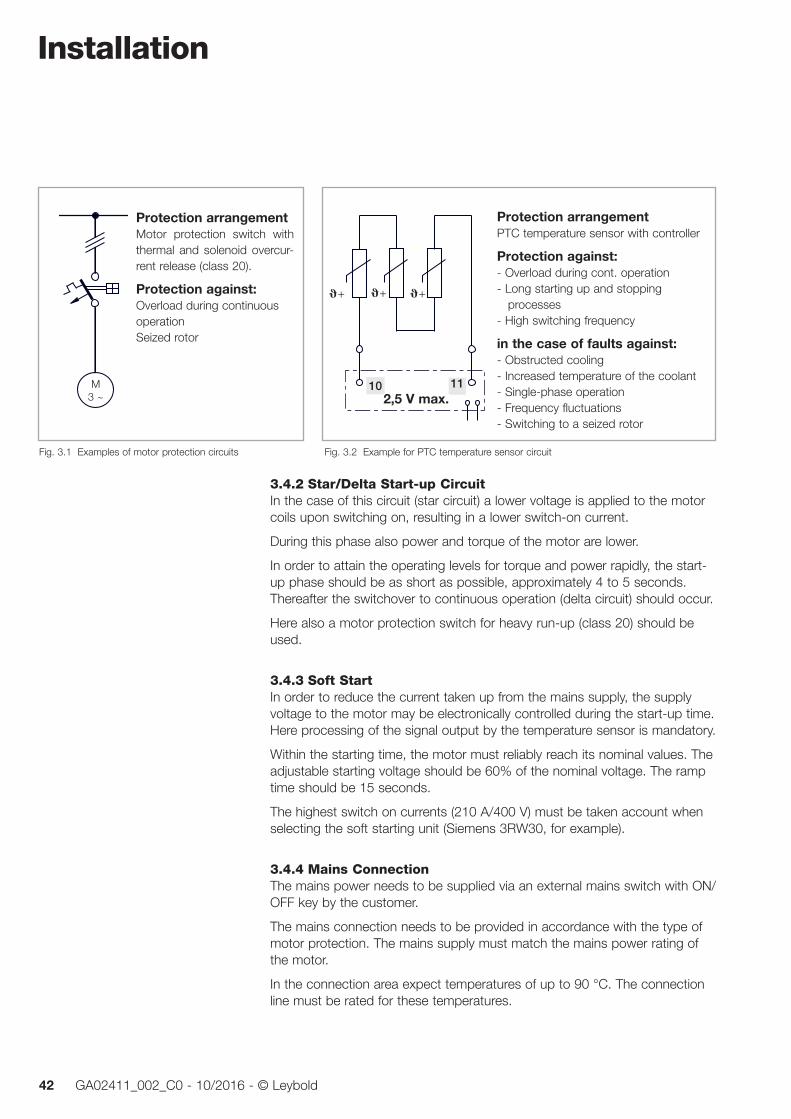
Fig. 3.2 Example for PTC temperature sensor circuit
Protection arrangement PTC temperature sensor with controller
Protection against: - Overload during cont. operation - Long starting up and stopping processes - High switching frequency
in the case of faults against: - Obstructed cooling - Increased temperature of the coolant - Single-phase operation - Frequency fluctuations - Switching to a seized rotor
10 11
+ + +
2,5 V max.
Fig. 3.1 Examples of motor protection circuits
Protection arrangement Motor protection switch with thermal and solenoid overcur-rent release (class 20).
Protection against: Overload during continuous operation Seized rotor
M3 ~

Installation
43GA02411_002_C0 - 10/2016 - © Leybold
32
31
30
29
28
27
26350 360 370 380 390 400 410 420 430 440 450
U
I
32
31
30
29
28
27
26
I
25
24
23
22350 370 390 510410 470430 490450
U530
Strom
Strom
Spannung
Spannung
50 Hz
60 Hz
∆
∆
18,5
17,3
16,2
15,0
Y
621 655 690 724 759
∆Y
∆
Diagram 1 Voltage/current diagram
Star / Delta
Delta
Cur
rent
Voltage
Cur
rent
Voltage
Installation
44 GA02411_002_C0 - 10/2016 - © Leybold
- Dreieck - Schaltung
- Stern - Schaltung
- Dreieck - Schaltung U/2
U2
V2
W2
U5
V5
W5
W6
U6
V6
U1
V1
W1
L1
L2
L3
- Stern - Schaltung U/2
PTC
10
11
3~ / 400 V (50 Hz)3~ / 460 V (60 Hz)
3~ / 200 V (50 Hz)3~ / 210 V (60 Hz)
Bei Stern-Schaltungkein Dauerbetrieb!
Bei Doppel-Ster n-Schaltungkein Dauerbetrieb!
PE
U2
V2
W2
U5
V5
W5
W6
U6
V6
U1
V1
W1
L1
L2
L3
U2
V2
W2
U5
V5
W5
W6
U6
V6
U1
V1
W1
L1
L2
L3
L1
L2
L3
U2
V2
W2
U5
V5
W5
W6
U6
V6
U1
V1
W1
PE
PE
PE
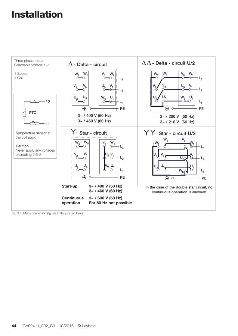
Fig. 3.3 Mains connection (figures in the junction box )
Temperature sensor in the coil pack
CautionNever apply any voltages exceeding 2.5 V
Three phase motorSelectable voltage 1:2
1 Speed1 Coil
Start-up 3~ / 400 V (50 Hz) 3~ / 460 V (60 Hz)
Continuous 3~ / 690 V (50 Hz) operation For 60 Hz not possible
In the case of the double star circuit, no continuous operation is allowed!
- Delta - circuit
Star - circuit
- Delta - circuit U/2
Star - circuit U/2
Installation
45GA02411_002_C0 - 10/2016 - © Leybold
Check the direction of rotation of the motor
During operation with an open intake flange there is the risk of suffering injury by rotating parts. For this reason do not check the direction of rota-tion with an open intake flange but instead vent the intake line through cor-respondingly switched valves.
With the fan housing open, there is the risk of suffering injury due to hot surfaces. Moreover, sufficient cooling of the pump is not ensured any more.
Except when checking the direction of rotation the pump must never be operated with its fan housing open.
Allowing the pump to run backwards with a closed intake line will immedi-ately damage the pump. Letting the pump run backwards for over three seconds will damage the pump regardless of the conditions.
As a rule, the pumps are supplied turning in the clockwise direction on the load side, with the direction of rotation being anticlockwise for the ventilation side
For the power connecting lines from the side of the customer a clockwise rotating field needs to be ensured. Please check this with a direction of rota-tion measuring instrument.
The direction of rotation should be checked with two persons.
Vent in the intake line through correspondingly switched valves. Open the fan housing.
Let the pump run up briefly (for approximately 1 second) and then immedi-ately switch it off again.
Observe the direction of rotation of the running down fan. The correct direc-tion of rotation is indicated by an arrow in the junction box.
In the case of a wrong connection, rewire.
Close the housing again.
CAUTION
NOTICE

Installation
46 GA02411_002_C0 - 10/2016 - © Leybold
3.4.5 Power Failure
When connecting the pump to a vacuum chamber, a suitable valve (electric shut-off valve, for example) needs to be connected on the intake side for interrupting the intake line so as to prevent the pump from running back-wards in the event of a power failure. Otherwise the pump may suffer dam-age.
This valve needs to be controlled (normally closed) from the side of the sys-tem controller such that the intake line is interrupted in the event of a power failure. This prevents an uncontrolled flow through the pump.
3.4.6 Operation with a Frequency Converter (FC Operation)FC operation serves the purpose of reducing the motors switch-on currents and serves the purpose of adapting the mains frequency to the nominal fre-quency of the pump.
During operation a frequency ranging from 30 Hz up to the nominal fre-quency of the pump must be set up. The nominal speed must not be exceeded. The run-up time to 30 Hz must not exceed 30 s.
As a rule, processing of the output from the temperature sensor in the motor is mandatory.
Depending on the level and quality of the output voltage from the frequency converter due to the additional heat produced by the coils, not all operating conditions may be set up continuously (back pressure and a simultaneous ambient temperature of 40 °C at maximum load, for example). For this rea-son, the output from the temperature sensor in the motor must be processed accordingly.
In connection with FC operation electromagnetic interference will have to be expected at significant levels. Here the personnel setting up the system must ensure that the limits laid down in the pertinent standards and guidelines are not exceeded. In order to reduce the level of electromagnetic interference, shielded motor cables, shielded cable feedthroughs, motor filters and EMC-compliant ground connections between FC and pump will be necessary.
Always also observe the information given in the Operating Instructions for the frequency converter.
3.5 Oil Temperature Sensor Pt 100The temperature of the oil is influenced by the load on the pump, the ambient temperature and the cleanness of the oil cooler.
The temperature of the oil may be measured by the system controller using the standard temperature sensor Pt 100 or via the SP-Guard (depending on the supplied pump version). The Pt 100 measures the temperature of the oil:
■ upstream of the oil cooler in the case of the air cooled pumps ■ downstream of the heat exchanger in the case of water cooled pumps.
NOTICE
NOTICE

Installation
47GA02411_002_C0 - 10/2016 - © Leybold
Maximum oil temperature for air cooling water cooling
Normal operation up to 80 °C 40 °C ± 3 °C, with the thermostatic valve set in the factory
Warning range over 80 °C over 60 °C Fault for ATEX operation
Fault for none- ATEX operation over 90 °C over 70 °C
In the case of ATEX operation the normal operation operating conditions must not be exceeded. The SP-Guard must be wired and integrated within the system controller so that the pump is shut down as soon as the warning range is reached.
If the temperature of the oil deviates during normal loads and ambient con-ditions from the process dependent standard values, the oil cooler should be checked to see if it has accumulated any dirt.
3.6 Connecting the Cooling Water(for water cooled pumps only)
Operation without cooling water will damage the pump.
Operate the pump only with the fan cover in place. The SP 630 F can suf-fer severe damage in the case of restricted cooling.
In the case of several pumps, each pump must be connected separately to the cooling water. A “series connection” of several pumps is not permis-sible as otherwise due to the control action of the thermostatic valves this may cause an interruption to the cooling water flow.
The pump is supplied without cooling water in the heat exchanger.
Unlock the quick locks at the fan covers (see fig. 4.2 or 4.3) and open the fan cover
The thermostatic valve (fig. 5.2) is set to 40 °C oil temperature as factory default.
Do not confuse water supply and return.
For the cooling water connections use only flexible hoses of sufficient pres-sure and temperature resistance.
Connect cooling water supply line and cooling water return.
Only at an oil temperature of approximately 40° C will the thermostat open and the cooling water flow. At 20° C this takes approximately 10 minutes.
Cooling water throughput may vary between 0 and 12 litres per minute depending on the temperature of the cooling water.
NOTICE
NOTICE

Installation
48 GA02411_002_C0 - 10/2016 - © Leybold
Fig. 3.4 SP 630 F - Connection of the cooling water
Supply
Return
Quick locks for opening the
fan cover
Connections for
cooling waterG 1/2”
Note the lettering!
SP-Guard
!Correctly connect the cooling water!

Installation
49GA02411_002_C0 - 10/2016 - © Leybold
3.6.1 Water QualityIn order to ensure long trouble-free operation the cooling water must not contain any oils, greases and suspended solids. Moreover, we recommend compliance with the following limit values:
Appearance Clear, free of oils and greases
Suspended matter < 250 mg/l
Particle size < 150 µm
Electrical conductivity < 700 µS/cm
pH value 7.0 to 9.0
Total hardness (total alkaline earths) < 8 °dH
Aggressive carbon dioxide None, not detectable
Chloride < 100 mg/l
Sulphates < 150 mg/l
Nitrate ≤ 50 mg/l
Iron < 0.2 mg/l
Manganese < 0.1 mg/l
Ammonium < 1.0 mg/l
Free chlorine < 0.2 mg/l
8 °dH (degrees German hardness) = 1.4mmol/l = 10 °e (degrees English hardness) = 14 °f (degrees French hardness)
If there is the danger of frost, you may use a water glycol mixture of up to 30 %.
DS water (softened or fully desalinated water) can be used for cooling the pump, if the pH value corresponds to the range indicated above.
Materials in the cooling circuit of the pump: AISI 304, AISI 316, copper sol-der, brass
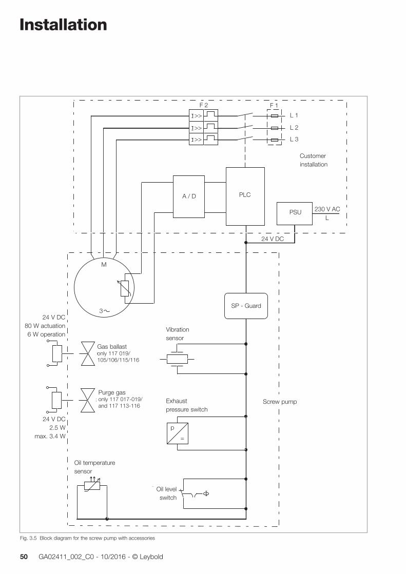
Installation
50 GA02411_002_C0 - 10/2016 - © Leybold
Ölstand-schalter
Vibrations-sensor
Öltemperatur-sensor
Auslassdruck-schalter
SP - Guard
M
3
>>
>>
>>
Netzteil
SPSA / D
24 V DC80 W Anzug6 W Betrieb
24 V DC2,5 W
max. 3,4 W
Schraubenpumpe
KundenseitigeInstallation
Gasballast
Sperrgas
230 V ACL
24 V DC
F 2 F 1
L 2
L 1
L 3
p
=
Fig. 3.5 Block diagram for the screw pump with accessories
Customer installation
PLC
PSU
Screw pump
Vibration sensor
Exhaust pressure switch
Oil level switch
Oil tempera ture sensor
24 V DC 80 W actuation 6 W operation
24 V DC 2.5 W
max. 3.4 W
Gas ballast only 117 019/ 105/106/115/116
Purge gas only 117 017-019/ and 117 113-116

Installation
51GA02411_002_C0 - 10/2016 - © Leybold
3.7 Connecting the SP-Guard
Only such power supply units may be connected which comply with the requirements of protective extra low voltage with safe isolation in ac cord-ance with IEC 60364-4-41 (DIN VDE 0100-410) (PELV/SELV).
To connect the SP-Guard, the supplied connection cable must be used. The connectors must be properly locked.
The power supply unit is connected as depicted in fig. 3.7.
The SP-Guard has an internal 0.6 amp fuse. This fuse must only be replaced by Leybold personnel.
No leakage currents must be allowed to flow via the SP-Guard and the sen-sors. Leakage currents will be present especially in the vicinity of strong sources of electromagnetic interference like frequency converters, for exam-ple. To reduce leakage currents, an EMC compliant ground connection (cop-per strap, for example) must be provided between the M8 tapped blind hole at the pump and the ground rail of the plant or source of interference.
The limit of 10 V/m laid down in the pertinent standards for industrial systems must not be exceeded in the case of field-related interference.
Pin Assignment Table for the Connection Cable
LIYCY 16 x AWG 26, black
1: white 24 V
2: brown Housing
3: -- Not connected
4: green 0 V
5: yellow Run to unused terminal
6: grey Electronics GND
7: pink Run to unused terminal
8: red Run to unused terminal
9: blue Run to unused terminal
10: black Run to unused terminal
11: violet 0 V (GND for PLC controller)
12: grey/pink Switching output S1 (warning)
13: red/blue Switching output S2 (error)
14: white/green Switching output S3 (watchdog)
15: brown/green Switching output S4 (pump on)
16: yellow/brown 0 V (GND for PLC controller)
17: -- Not connected
Shield For connection, see fig. 3.7
CAUTION
Fig. 3.6 Ground connection example

Installation
52 GA02411_002_C0 - 10/2016 - © Leybold
Do not unplug the connectors of the SP Guard while still being under volt-age. There exists the risk of igintion!
All connectors are protected against mechanical influences thanks to the housing covers. Do not operate the pump without its covers!
Outputs at the SP-Guard (S1 - S4)The outputs S1 - S4 of the SP-Guard are provided with push-pull driver out-put stages (transistor connection between +Vcc and GND). Correspondingly, the high level is at 1 V below the power supply voltage level and the low level is at approximately 1 V.
The maximum current rating is 40 mA.
The outputs are protected by means of semiconductor fuses.
CAUTION
Abb. 3.7 Electrical connection - Power supply for status outputs
SP - Guard
Sensors
Mains connection~~
1 / white
4 / green
11 / violet
16 / yellow/brown
12 / grey/pink
13 / red/blue
SPS
2 / brown
S1
S2
S4
+ 24 V DC
0 V DC
S315 / brown/green
PE
L1
N
PE
Power supply
14 / white/green
GND
GND
6 / grey
0V
0V
optional
optional
S�ield
�ilter�u�per
optional
GND
+ Vcc
40 mA
Abb. 3.8 Signal output diagram
24 V
(S1... S4) + Vcc
0 V Low
High∆U 1 V
∆U 1 V
0 V

Installation
53GA02411_002_C0 - 10/2016 - © Leybold
The failure messaging output S2 is active (low) until being reset. The warning messaging output S1 remains active as long as the warning threshold is exceeded (no saving of the status).
During the start-up phase of the pump, the sensor signals are processed dif-ferently so that displayed values may exceed the parameter values stated in the table.
Parameter values
Parameter Default settings Unit Description SP 630 SP 630 F
a 100 100 digits Warning limit, vibrations
b 150 150 digits Failure limit, vibrations
c 10 10 0,2 s Hysteresis, vibration meas.
d 80 60 °C Warning limit, oil temperature Failure limit for ATEX operation
e 90 70 °C Failure limit, oil temperature for non-ATEX operation
o 20 20 digits “Pump on” threshold
switch logic = off (default)
Status Table for the Switching Outputs
Outputs
Designation Warning Failure Pump on Watchdog
Abbreviation S1 S2 S4 S3
Plug contact 12 13 15 14
Status Status Failure/Warning Rotor
-/- standstill high high high hi-lo-hi (1s)
-/- turning high high low hi-lo-hi (1s)
Warning level exceeded low low high high hi-lo-hi (1s)
Warning level exceeded turning low high low hi-lo-hi (1s)
Filure level exceeded standstill low low high hi-lo-hi (1s)
Filure level exceeded turning low low low hi-lo-hi (1s)
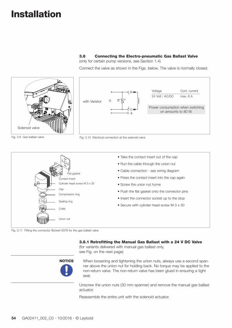
Installation
54 GA02411_002_C0 - 10/2016 - © Leybold
3.8 Connecting the Electro-pneumatic Gas Ballast Valve(only for certain pump versions, see Section 1.4)
Connect the valve as shown in the Figs. below. The valve is normally closed.
3.8.1 Retrofitting the Manual Gas Ballast with a 24 V DC Valve(for variants delivered with manual gas ballast only, see Fig. on the next page)
When loosening and tightening the union nuts, always use a second span-ner above the union nut for holding back. No torque may be applied to the non-return valve. The non-return valve has been glued in ensuring a tight seal.
Unscrew the union nuts (30 mm spanner) and remove the manual gas ballast actuator.
Reassemble the entire unit with the solenoid actuator.
NOTICE
Fig. 3.10 Electrical connection at the solenoid valve
with Varistor
Power consumption when switchingon amounts to 80 W.
Fig. 3.11 Fitting the connector Bürkert 8376 for the gas ballast valve
• Take the contact insert out of the cap
• Run the cable through the union nut
• Cable connection - see wiring diagram
• Press the contact insert into the cap again
• Screw the union nut home
• Push the flat gasket onto the connector pins
• Insert the connector socket up to the stop
• Secure with cylinder head screw M 3 x 30
Flat gasket
Contact insert
Cylinder head screw M 3 x 30
Cap
Compression ring
Sealing ring
Collet
Union nut
Fig. 3.9 Gas ballast valve
Solenoid valve
Voltage Cont. current
24 Volt / AC/DC max. 6 A

Installation
55GA02411_002_C0 - 10/2016 - © Leybold
3.9 Connecting the Purge Gas Valve(only for certain pump versions, see Section 1.4)
In the case of ATEX applications conforming utilisation requires mandatory operation with purge gas.
Connect the valve as shown in the Figs. below. The valve is normally closed.
Connect the purge gas: admission pressure into the pressure reducer 3-10 bar (g) (to be provided from the side of the customer).
24 V DC
1 +
2 - Valve
Fig. 3.13 Electrical connections at the purge gas valve
Fig. 3.14 Connecting the plug and the purge gas at the purge gas valve
Purge gas connection - G 1/8" inside thread
Loosen screw and pull the plug
Fig. 3.12 Retrofitting the manual gas ballast with a 24 V DC valve
manual gas ballas Gas ballast with 24 V DC valve
Conversion
union nutsNon-return valve
Operation
56 GA02411_002_C0 - 10/2016 - © Leybold
4 Operation
4.1 Start-up
The pump must only be commissioned by trained staff.
4.1.1 Oil Filling for the Gear
The SP 630/SP 630 F is supplied without oil in its gear. Before commis-sioning, the separately supplied gear oil must be filled into the gear.
When doing so make sure that all aids used are clean so as to avoid con-taminating the oil.
Use only lubricating oil which has been approved by Leybold.
The gear oil should be filled in at room temperature. At lower temperatures, the oil is thicker so that there then is the risk of overfilling gear chamber with oil.
For filling in oil, the cover section on the discharge side must be disassem-bled see fig. 4.2 or 4.3. For this unlock the closure screws at the cover and remove the cover section(s).
For the closure screws you will require a special square key. This key is included in the delivery.
Remove the oil fill plug and fill in the lubricant. When doing so, make sure that the oil level, after filling, will be at the level of the maximum mark (see fig. 4.1).
The total oil filling quantity is 15 litres. Since after the test run and after having drained out the lubricant some oil remains within the pump, approximately only 12 litres of oil are filled in during first-time commissioning and when changing the oil.
Overfilling the gear chamber can result in leakages through the drain and also into the pump chamber.
Clean the oil fill port and screw the oil fill plug in again using a gasket which is in perfect condition.
The oil fill port must be sealed air-tight.
For checking the oil level and for changing the oil see Section 5.1.
When switching the pump on and off the oil level may fluctuate visibly. During operation of the pump the oil level will be between the maximum and the minimum mark. As soon as the oil level during operation of the pump drops to the minimum mark, oil must be topped up
After having filled in the oil, the cover must be fitted once more.
The two cover sections are fitted in the reverse order. While fitting, the pegs at the cover sections must engage into the corresponding bores. This will ensure that the cover sections are properly seated and, moreover, otherwise the covers cannot be properly fitted.
4.1.2 Switching the Pump On
CAUTION
NOTICE

Operation
57GA02411_002_C0 - 10/2016 - © Leybold
1 Junction box2 Oil sight glass3 Oil fill plug4 Oil drain plug5 Oil level mark ”Maximum”6 Oil level mark ”Minimum”7 Ground contact
1
2
3
4
5
6
7
Fig.4.1 Oil level, oil sight glass and junction box (pump with covers removed)
Pump not in operation Oil level maximum (for initial filling)
Oil level
Öl
Öl
Öl
Maximum markat the oil sight glass
Minimum mark at the oil sight glass
Öl
Öl
Maximum markat the oil sight glass
Minimum mark at the oil sight glass
Oil level
Pump operating Oil level between maximum and minimum
Maximum markat the oil sight glass
Minimum mark at the oil sight glass
Oil level
Pump operating Oil level at minimum (top up oil!)
Öl
Öl
Öl
Float
Float
Float

Operation
58 GA02411_002_C0 - 10/2016 - © Leybold
Fig. 4.2 Unlocking the closure screws and removing the undivided cover section
X
X
X
X
X
X
X
1 Cover section/discharge side2 Panel for guiding the discharged air
Closure screws (7x) 1
X
2
Luftaustrittsblech
linke Verkleidungshälfteder Serviceseite
rechte Verkleidungshälfteder Serviceseite
rückseitiges Verkleidungsteil
= Verschluss-Schrauben (9 Stück)
Fig. 4.3 Unlocking the closure screws and removing the divided cover section
Rear cover section
Air discharge panel
Left cover section on the service side
Right cover section on the service side
Closure screws (9 pieces)
Operation
59GA02411_002_C0 - 10/2016 - © Leybold
The pump may only be switched on after it has been completely assem-bled and with the fan’s housing closed.
Operation without intake and discharge lines or silencer is not allowed.
In the discharge line no pressure > pex = pamb + 200 mbar must be allowed to build up even if the discharged gases need to be collected or contained.
Make sure that the gas flow at the discharge is not blocked or restricted in any way.
Depending on the pump version switch on
■ cooling water
■ power supply for the SP-Guard
■ gas ballast
■ purge gas
Then switch on the pump.
Start the pump only six times per hour at the most so as to avoid over-loading the motor.
Between pumping chamber and gear, the pump has been equipped with non-contacting seals. These seals have been provided with a vent at the bot-tom side of the pump. Small quantities of gear oil can escape from this vent. This will in no way influence safe operation of the pump.
Please note safety information 0.4.7.
The motor casing is vented through a channel which opens next to the motor junction box. From this vent small quantities of gear oil can escape. This will not have a negative influence on safe operation of the pump.
For water cooled pumps only
Thermostat settings 4 and 5 must not be set up since damage may occur due to inadequate cooling.
At water temperatures exceeding 25° C the thermostat will no longer be able to maintain a constant oil temperature. The air cooling share will then increase.
CAUTION
NOTICE
NOTICE
Operation
60 GA02411_002_C0 - 10/2016 - © Leybold
4.2 OperationThe pump should normally be operated continuously. If possible do not switch the pump off for less than one hour. In the case of process interrup-tions preferably operate the pump with the inlet shut off, since during opera-tion at ultimate pressure power consumption will be minimal.
The pump will have attained its operating temperature about 30 minutes after starting.
Before pumping condensable vapours the pump should have attained its operating temperature first.
The highest permissible intake pressure is 55 mbar above ambient pres-sure.
The permissible pressure at the discharge flange is pdis = pamb + 200 mbar/- 50 mbar. Make sure that the gas flow at the discharge is in no way blocked or restricted and that no pressure can build up.
After having commissioned the pump and after the pump has been at stand-still for a longer period of time, the pump may generate more noise than usual. This noise is caused by the low viscosity of the oil at low oil tempera-tures. As the oil temperature increases the noise level will drop. The increased noise level will not adversely affect the operational reliability of the pump.
4.2.1 Operation with SP-GuardDuring constant pump operation, the vibration levels will commonly range between 40...80 digits.
During the switching on process, these values may be exceeded considera-bly for the few seconds. This has been taken into account by the SP-Guard and will not cause a shutdown of the pump.
The SP Guard receives a “pump running” signal from the vibration sensor. With overriding the “limit pump on” threshold the sensor outputs the “pump running” signal. This is when the hours counter starts.
With a faulty vibration sensor or connection the pump may be running with-out corresponding feedback signals from the SP Guard. Thus we recom-mend to synchronize the “pump on” signal of the higher-level control with the “pump running” signal of the SP Guard and output a corresponding warning or error message, if necessary.
In the case of ATEX operation an error message must be output, which results in shutting down the pump.
Resetting the SP-GuardA reset will only be possible after the fault cause has been remedied.
In order to reset the SP-Guard after a malfunction, operate the pushbutton located on the right-hand housing side as follows: Press the pushbutton - long (3 seconds), and then short twice. A confirmation of the resetting pro-cess will be indicated on the display for approximately 5 seconds.
NOTICE
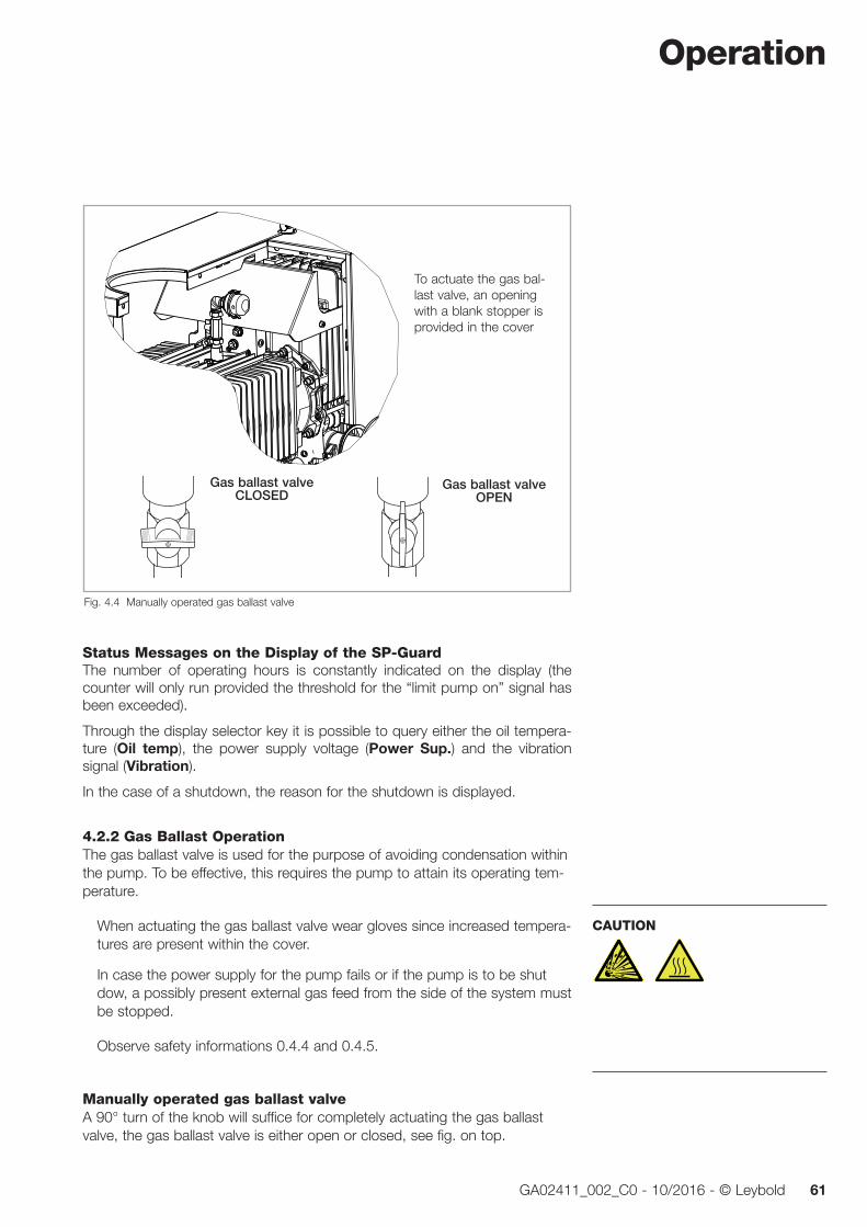
Operation
61GA02411_002_C0 - 10/2016 - © Leybold
Status Messages on the Display of the SP-GuardThe number of operating hours is constantly indicated on the display (the counter will only run provided the threshold for the “limit pump on” signal has been exceeded).
Through the display selector key it is possible to query either the oil tempera-ture (Oil temp), the power supply voltage (Power Sup.) and the vibration signal (Vibration).
In the case of a shutdown, the reason for the shutdown is displayed.
4.2.2 Gas Ballast OperationThe gas ballast valve is used for the purpose of avoiding condensation within the pump. To be effective, this requires the pump to attain its operating tem-perature.
When actuating the gas ballast valve wear gloves since increased tempera-tures are present within the cover.
In case the power supply for the pump fails or if the pump is to be shut dow, a possibly present external gas feed from the side of the system must be stopped.
Observe safety informations 0.4.4 and 0.4.5.
Manually operated gas ballast valveA 90° turn of the knob will suffice for completely actuating the gas ballast valve, the gas ballast valve is either open or closed, see fig. on top.
CAUTION
Gas ballast valveOPEN
Gas ballast valveCLOSED
Fig. 4.4 Manually operated gas ballast valve
To actuate the gas bal-last valve, an opening with a blank stopper is provided in the cover

Operation
62 GA02411_002_C0 - 10/2016 - © Leybold
Electro-pneumatic gas ballast valveSee Fig. 3.9 to 3.11. The valve is normally closed.
4.2.3 Purge Gas Operation(only for certain pump versions, see Section 1.4)
For conforming utilisation of the SP 630 (F) ATEX, operation with purge gas is mandatory.
In order to ensure full protection by the purge gas, the inlet pressure of the purge gas into the pressure reducer must be within the range of 3 to 10 bar.
At the pressure reducer, a system pressure of 2.5 bar needs to be set up . At this setting there results a purge gas flow of approximately 20 Std. l/min.
Always switch on the purge gas first and then the pump.
After having switched off the pump, the seals should be purged at least for one further hour with purge gas. Depending on the type of process gas which was pumped, an even longer purging time may be required.
During the purging time, the blocking facilities installed in the exhaust line must be open, as otherwise and unacceptably high pressure might build up within the pump.
At the maximum permissible pressure difference between the exhaust of the pump and atmosphere of +200 mbar, a maximum purge gas flow of 8 Std. l/min may escape into the environment.
When using nitrogen as the purging gas, ensure sufficient ventilation of the location where the pump is installed.
Operation with purge gas does in no way influence the pumping speed of the pump.
The purge gas flow is continuously monitored while the SP Guard is supplied with voltage. Therefore the SP Guard displays an error message when the pump is at a standstill and there is no gas flow. Thus we recommend the fol-lowing power-off sequence: pump, SP Guard, purge gas. Switch on the pump in reverse order.
CAUTION
Fig. 4.5 Adjust the pressure reducer
To adjust, pull the blue adjustment knob to the right, set to 2.5 bar, and for the purpose of securing the adjustment knob, push it to the left and arrest it.
Operation
63GA02411_002_C0 - 10/2016 - © Leybold
An error message will be displayed (and must be acknowledged), if the purge gas will be turned off prior to the SP Guard or turned on after the SP Guard.
4.2.4 Regular Checks
(Note also Section 5 “Maintenance”)
Reliable and safe operation is ensured when running the following checks regularly:
■ Oil level check
■ Check on the oil cooler for accumulated dirt
■ Emptying the condensate separator (optional)
■ Check the readings on the SP-Guard (optional) (temperatures and vibration levels)
■ Cleaning the filter at the gas ballast valve (optional)
■ Cleaning the intake screen
■ Checking the dust filter (optional) and cleaning as required
In the case of ATEX applications we recommend keeping a log on the regular checks. Stop operating the pump when the SP-Guard displays a warning.
A wire-mesh filter is located in the pump’s intake port to act as an intake screen for foreign items. It should be kept clean at all times in order to avoid reduction of the pumping speed.
For this purpose, disconnect the intake line, remove the intake screen from the intake port and clean it in a suitable way. If the intake screen is defective, replace it.
The cleaning intervals depend on requirements. If large amounts of abrasive materials occur, a suitable dust filter should be fitted into the intake line.
The interval between the regular checks will depend on the ambient condi-tions and the process in each case and needs to be defined based on expe-rience gained during operation. The temperature of the oil and the dirt accu-mulated on the oil cooler will have to be checked more frequently when the pump is being operated in a dusty environment. If much condensate is col-lected, the condensate separator will have to be checked regularly.

Operation
64 GA02411_002_C0 - 10/2016 - © Leybold
4.3 Switching Off/Shutting DownClose the intake line.
Switch the pump off.
The pressure in a pump which has been switched off will increase within a few seconds to the level of the discharge pressure (normally = ambient pres-sure). The SP 630 is not equipped with any means to protect the vacuum. For this reason use, if needed, a valve (anti-suckback valve) fitted in the intake line which will automatically close the intake port of the pump upon standstill of the pump, for example, SECUVAC valve.
In order to prevent damage due to standstill of the pump, a post operation phase of at least 15 minutes with the gas ballast open is recommended after termination of the process, if the process gas contains corrosive, con-densable substances or substances which tend to form deposits.
In the case of prolonged standstill times (over three weeks) further meas-ures besides letting the pump run idle need to be introduced for the pur-pose of avoiding corrosion due to standstill, see Section 2 “Storing”.
For this please contact Leybold for advice.
Depending on the pump version switch off
■ power supply for the SP-Guard
■ gas ballast
■ purge gas
■ Shut off the water cooling circuit. When cooling the system during stand-still, condensation will occur which will cause corrosion over time.
Water Cooled PumpsIn the case of water cooled pumps drain out the cooling water before trans-porting the pumps.
■ Open the fan cover.
■ Fully open the thermostatic valve; position below 1.
■ Disassemble the water connections on the side of the customer’s system and blow out the heat exchanger with compressed air.
■ Again lock the fan cover in place.
If the SP 630 F is stored in an environment which is not free of frost, then the heat exchanger must also be emptied.
NOTICE
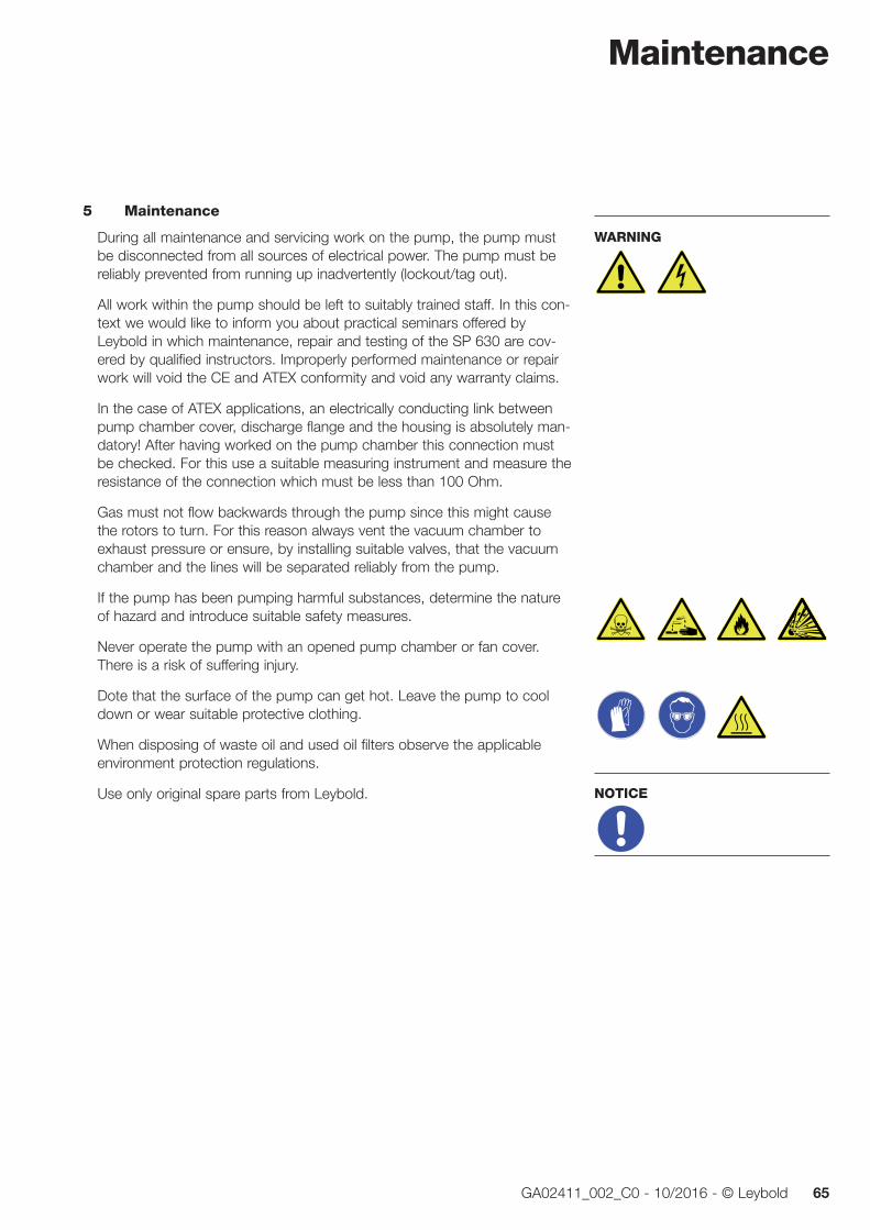
Maintenance
65GA02411_002_C0 - 10/2016 - © Leybold
5 Maintenance
During all maintenance and servicing work on the pump, the pump must be disconnected from all sources of electrical power. The pump must be reliably prevented from running up inadvertently (lockout/tag out).
All work within the pump should be left to suitably trained staff. In this con-text we would like to inform you about practical seminars offered by Leybold in which maintenance, repair and testing of the SP 630 are cov-ered by qualified instructors. Improperly performed maintenance or repair work will void the CE and ATEX conformity and void any warranty claims.
In the case of ATEX applications, an electrically conducting link between pump chamber cover, discharge flange and the housing is absolutely man-datory! After having worked on the pump chamber this connection must be checked. For this use a suitable measuring instrument and measure the resistance of the connection which must be less than 100 Ohm.
Gas must not flow backwards through the pump since this might cause the rotors to turn. For this reason always vent the vacuum chamber to exhaust pressure or ensure, by installing suitable valves, that the vacuum chamber and the lines will be separated reliably from the pump.
If the pump has been pumping harmful substances, determine the nature of hazard and introduce suitable safety measures.
Never operate the pump with an opened pump chamber or fan cover. There is a risk of suffering injury.
Dote that the surface of the pump can get hot. Leave the pump to cool down or wear suitable protective clothing.
When disposing of waste oil and used oil filters observe the applicable environment protection regulations.
Use only original spare parts from Leybold.
WARNING
NOTICE
Maintenance
66 GA02411_002_C0 - 10/2016 - © Leybold
5.1 Checking the Oil LevelThe intervals between the regular checks should be based on the ambient conditions and your experience.
Upon switching the pump on and off, the oil level may fluctuate visibly.
With the pump at standstill the oil level must be between the maximum and the minimum mark (see fig. 4.1). As soon as the oil level during operation of the pump drops to the minimum mark, oil must be topped up.
When determining the correct oil level at the oil sight glass, the oil level itself is decisive and not the upper edge of the float!
5.1.1 Oil Change and Oil Filter Change
While it is still warm, the oil can cause burns. Use the ne cessary protection equipment.
Change the oil while it is still warm and only while the pump is at standstill. Place a sufficiently large collecting vessel (about 20 litres) under the pump.
When disposing of the waste oil observe the applicable environment pro-tection regulations.
Use only lubricants approved by Leybold.
To change the oil, the cover section on the discharge side needs to be disas-sembled, see fig. 4.2 or 4.3.
Unscrew the oil drain plug and the oil fill plug and drain out the oil. See fig. 4.1.
Clean the sealing surface and firmly screw in the oil drain plug using a gasket which is in perfect condition. Wipe off any oil residues on the housing.
Replacing the Oil FilterOpen the fan’s housing and screw the oil filter housing open, see fig. 5.1 (place a collecting vessel for the small amount of oil underneath).
Remove the filter and replace it by a new one. Thereafter close the filter housing and the fan’s housing once more.
CAUTION
NOTICE

Maintenance
67GA02411_002_C0 - 10/2016 - © Leybold
Exchanging the OilFill in the fresh gear oil.
When doing so, make sure that the aids used are clean so as to avoid contaminating the oil.
Clean the oil fill opening and screw on the oil fill plug using a gasket which is in perfect condition. Wipe off any oil residues from the housing.
The oil fill opening must be sealed off air-tight.
With the pump at standstill the oil level must be between the maximum and the minimum mark.
After having exchanged the oil, the cover section on the discharge side must be fitted once more, see fig. 4.2 or 4.3.
What to do when too much Oil has been filled inIf too much oil was filled in then there is the risk that the oil may spill into the bottom trough and the pump chamber.
1. With the pump at standstill, drain out so much oil that the oil level drops below the maximum mark.
2. Operate the pump for at least one hour.
3. Check the oil level once more and remove possibly escaped oil from the bottom trough.
4. It is to be expected that the pump will continue to lose small quantities of oil from the drain openings.
NOTICE
NOTICE
1 Inspection opening for the oil cooler2 Fan housing3 Oil cooler4 Oil filter housing
Fig. 5.1 Opened fan housing
1
4
2
3
Direction of rotation for the fan

Maintenance
68 GA02411_002_C0 - 10/2016 - © Leybold
5.2 Cleaning the Oil Cooler
Switch the pump off and ensure that it can not be started up inadvertently.
When blowing out with compressed air, protect your eyes and wear pro-tective goggles.
Regularly check the oil cooler to see if it has accumulated dirt.
The interval between the regular checks will depend on the ambient condi-tions and the process in each case and needs to be defined based on expe-rience gained during operation.
For this run a visual inspection through the inspection opening on top of the cooling unit, see fig. 5.1.
A dirty cooler may cause increased oil and pump temperatures and impair operation and reduce the service life of the pump.
With the pump at standstill, the fan’s housing may be opened so as to clean the oil cooler.
Open the fan’s housing and clean the cooler with compressed air from the accessible side.
If it is not possible to stop the pump, then in such a case the cooler may, if required, be cleaned from the top through the inspection opening using a vacuum cleaner.
5.3 Draining Out Condensate (optional)
To drain the condensate out, the pump must be separated from the pro-cess by a valve. Please note that process gases and condensate may pre-sent a hazard to health.
The optional silencer (P/N 119 002) has a condensate drain. Possibly present liquid which has collected in the silencer can be drained out through the con-densate drain.
The silencer must be checked regularly especially if much condensate is col-lected. Drain out condensate if required.
The interval between the regular checks will depend on the ambient condi-tions and the process in each case and needs to be defined based on expe-rience gained during operation.
5.4 Cleaning the Dust Filter in the Intake Line (optional)
The dust filters which are installed upstream of the pump need to be checked regularly for contamination and cleaned as required.
CAUTION
CAUTION
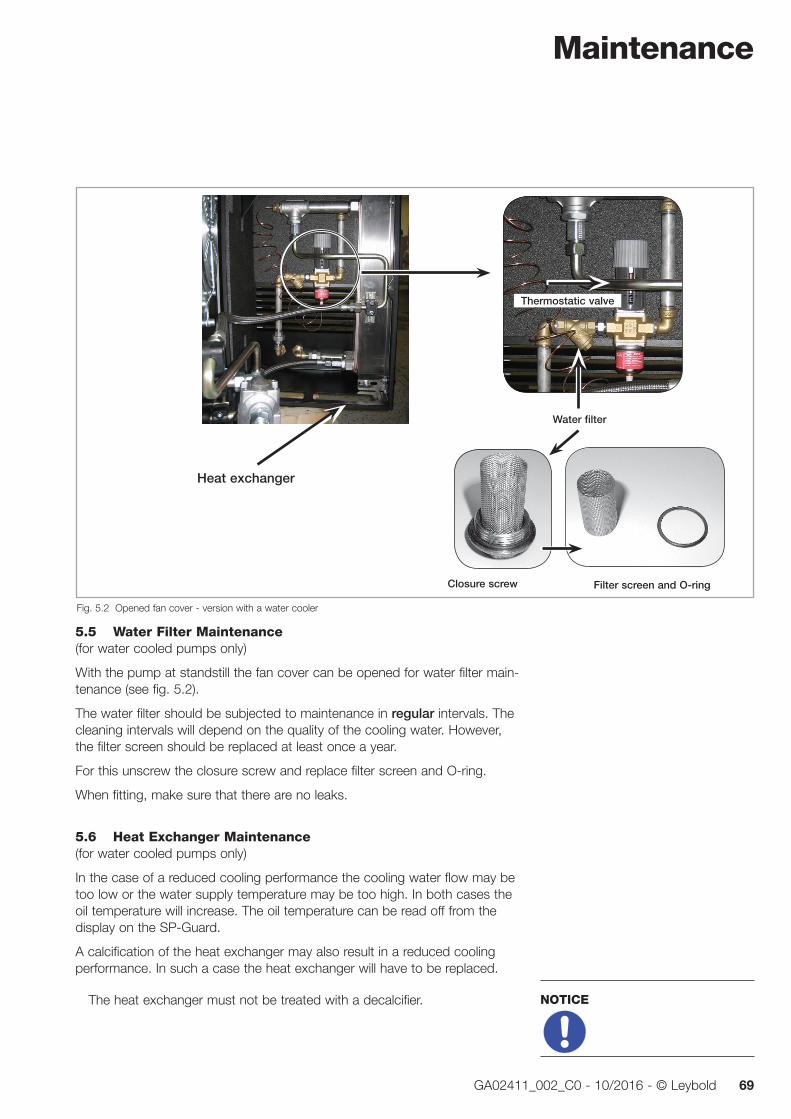
Maintenance
69GA02411_002_C0 - 10/2016 - © Leybold
5.5 Water Filter Maintenance(for water cooled pumps only)
With the pump at standstill the fan cover can be opened for water filter main-tenance (see fig. 5.2).
The water filter should be subjected to maintenance in regular intervals. The cleaning intervals will depend on the quality of the cooling water. However, the filter screen should be replaced at least once a year.
For this unscrew the closure screw and replace filter screen and O-ring.
When fitting, make sure that there are no leaks.
5.6 Heat Exchanger Maintenance(for water cooled pumps only)
In the case of a reduced cooling performance the cooling water flow may be too low or the water supply temperature may be too high. In both cases the oil temperature will increase. The oil temperature can be read off from the display on the SP-Guard.
A calcification of the heat exchanger may also result in a reduced cooling performance. In such a case the heat exchanger will have to be replaced.
The heat exchanger must not be treated with a decalcifier.
NOTICE
Fig. 5.2 Opened fan cover - version with a water cooler
Thermostatic valve
Water filter
Closure screw Filter screen and O-ring
Heat exchanger
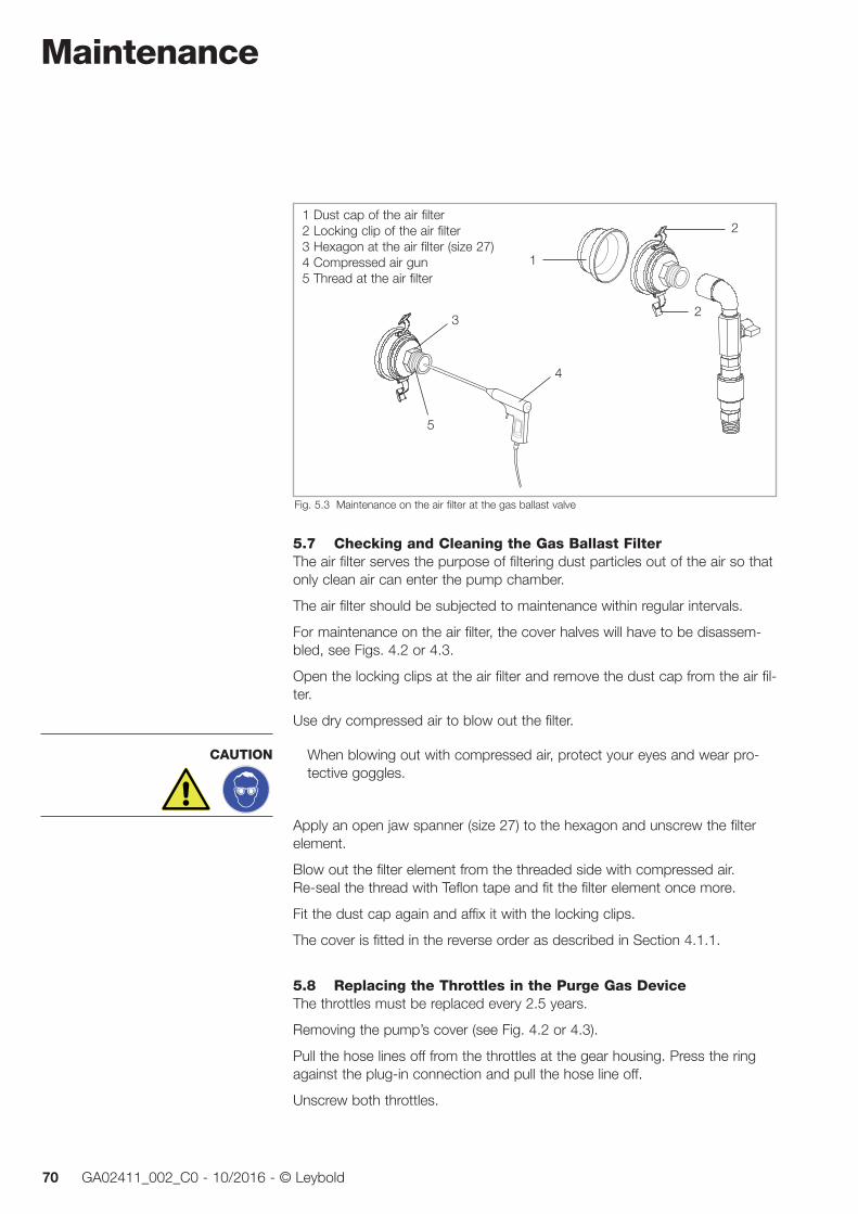
Maintenance
70 GA02411_002_C0 - 10/2016 - © Leybold
5.7 Checking and Cleaning the Gas Ballast FilterThe air filter serves the purpose of filtering dust particles out of the air so that only clean air can enter the pump chamber.
The air filter should be subjected to maintenance within regular intervals.
For maintenance on the air filter, the cover halves will have to be disassem-bled, see Figs. 4.2 or 4.3.
Open the locking clips at the air filter and remove the dust cap from the air fil-ter.
Use dry compressed air to blow out the filter.
When blowing out with compressed air, protect your eyes and wear pro-tective goggles.
Apply an open jaw spanner (size 27) to the hexagon and unscrew the filter element.
Blow out the filter element from the threaded side with compressed air. Re-seal the thread with Teflon tape and fit the filter element once more.
Fit the dust cap again and affix it with the locking clips.
The cover is fitted in the reverse order as described in Section 4.1.1.
5.8 Replacing the Throttles in the Purge Gas DeviceThe throttles must be replaced every 2.5 years.
Removing the pump’s cover (see Fig. 4.2 or 4.3).
Pull the hose lines off from the throttles at the gear housing. Press the ring against the plug-in connection and pull the hose line off.
Unscrew both throttles.
CAUTION
1
2
2
Fig. 5.3 Maintenance on the air filter at the gas ballast valve
3
4
5
1 Dust cap of the air filter2 Locking clip of the air filter3 Hexagon at the air filter (size 27)4 Compressed air gun5 Thread at the air filter

Maintenance
71GA02411_002_C0 - 10/2016 - © Leybold
Connect the new throttles to the hose lines. Insert the hose right up to the stop.
Apply pressure to the supply unit and open the switch-on valve.
Check to see that gas comes out at both new throttles. The flowing gas must be easily audible.
Close the switch-on valve (de-energise).
Pull the hose lines off from the throttle (press the ring against the connector).
Fig. 5.4 Pull the hose lines off from the throttles
Fig. 5.5 Unscrew both throttles
Bottom side of thegear housing
Fig. 5.6 Check the new throttles Fig. 5.7 Set up the pressure at the supply unit.
Maintenance
72 GA02411_002_C0 - 10/2016 - © Leybold
Use Teflon tape to seal off the threads of the throttles.
Screw the throttles into the gear housing.
Again insert the hose lines into the throttles right up to the stop.
Fit the pump cover again.
5.9 Service at Leybold If you send a pump to Leybold indicate whether the pump is free of sub-stances damaging to health or whether it is contaminated.
If it is contaminated also indicate the nature of the hazard. To do so, you must use a preprinted form which we shall send to you upon request.
A copy of this form is reproduced at the end of these Operating Instructions: “Declaration of Contamination of Compressors, Vacuum Pumps and Components”. Moreover, you may download a suitable form from the Internet: www.leybold.com Docu ments Download Documents.
Please attach this form to the pump or enclose it with the pump.
This “Declaration of Contamination” is required to meet the requirements of German Law and to protect our personnel.
Leybold must return any pumps without a “Declaration of Contamination” to the sender’s address.
Before packaging (respectively shipping) the pump it should, if possible, be purged with inert gas, but as a minimum requirement it should be completely emptied of all pumped substances.
This may also apply to all parts belonging to the pump system, like coolers, vessels, etc.
Package the pump so that it will not be damaged during shipping and so that no hazardous substances can escape from the packaging.
Before transporting the pump, drain out the oil!
For transporting, the pump has been fitted on to a special pallet, please retain this pallet in case the pump needs to be returned.
CAUTION
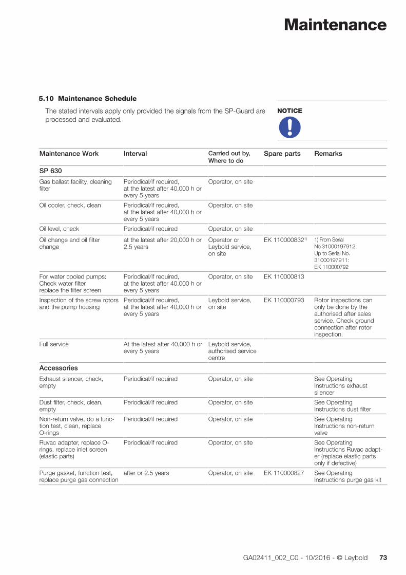
Maintenance
73GA02411_002_C0 - 10/2016 - © Leybold
5.10 Maintenance Schedule
The stated intervals apply only provided the signals from the SP-Guard are processed and evaluated.
NOTICE
Maintenance Work Interval Carried out by, Where to do
Spare parts Remarks
SP 630
Gas ballast facility, cleaning filter
Periodical/if required, at the latest after 40,000 h or every 5 years
Operator, on site
Oil cooler, check, clean Periodical/if required, at the latest after 40,000 h or every 5 years
Operator, on site
Oil level, check Periodical/if required Operator, on site
Oil change and oil filter change
at the latest after 20,000 h or 2.5 years
Operator or Leybold service, on site
EK 1100008321) 1) From Serial No.31000197912. Up to Serial No. 31000197911: EK 110000792
For water cooled pumps: Check water filter, replace the filter screen
Periodical/if required, at the latest after 40,000 h or every 5 years
Operator, on site EK 110000813
Inspection of the screw rotors and the pump housing
Periodical/if required, at the latest after 40,000 h or every 5 years
Leybold service, on site
EK 110000793 Rotor inspections can only be done by the authorised after sales service. Check ground connection after rotor inspection.
Full service At the latest after 40,000 h or every 5 years
Leybold service, authorised service centre
Accessories
Exhaust silencer, check, empty
Periodical/if required Operator, on site See Operating Instructions exhaust silencer
Dust filter, check, clean, empty
Periodical/if required Operator, on site See Operating Instructions dust filter
Non-return valve, do a func-tion test, clean, replace O-rings
Periodical/if required Operator, on site See Operating Instructions non-return valve
Ruvac adapter, replace O- rings, replace inlet screen (elastic parts)
Periodical/if required Operator, on site See Operating Instructions Ruvac adapt-er (replace elastic parts only if defective)
Purge gasket, function test, replace purge gas connection
after or 2.5 years Operator, on site EK 110000827 See Operating Instructions purge gas kit

Troubleshooting
74 GA02411_002_C0 - 10/2016 - © Leybold
6 TroubleshootingBefore starting any troubleshooting, you should check the following simple things:
■ Have all connectors been properly plugged in and secured at the SP-Guard and at all sensors?
■ Has the DC power supply been provided to the SP-Guard?
Malfunction / SP-Guard display
Possible cause Remedy Responsibility
Failure oil temp Oil temperature has exceeded the error threshold.
Temporary temperature increase during shutdown due to reduced cooling.
After switching off the pump open the cooling unit and clean the heat exchanger with com-pressed air.
Wait for the cooling down phase to complete.
Maintenance per-sonnel
Operator
Failure vibration Vibration level has exceeded the error threshold.
There are foreign objects or deposits in the pump.
Check whether there is in the immediate vicinity of the pump a different vibration source.
Contact our service technician.
Operator and maintenance per-sonnel
Failure exhaust pressure
Exhaust pressure exceeds the max. permissible pressure of 1200 mbar.
Check to see if the exhaust line is blocked. Remove blockage.
Operator and maintenance per-sonnel
Failure oil level Oil level drops below the minimum. With the pump at standstill top up oil until the oil level is again within the optimum range. Note any visible losses of oil and if required contact our service.
Maintenance per-sonnel
vibration > 20 with the pump at standstill.
Inadequate potential equalisation causes leakage currents via the SP-Guard.
Emitted interference
Conducted interference
Loose connector
Separate power supply output GND / 0V from PE to stop leakage currents. Note the local regulations regarding installa-tion and operation of safety extra-low voltage (SELV) systems. If required, connect the pump to ground through additional ground connec-tions.
For the purpose of complying with the maxi-mum permissible limits for a emitted interferenc-es, shielded cables between frequency con-verter and screw pump must be used, if required.
In order to reduce conducted interferences, use a motor filter at the output of the frequency converter, if required.
The power supply connector at the SP-Guard must be checked to ensure that it is firmly seat-ed.
Maintenance staff
Maintenance staff
Maintenance staff
Maintenance staff
Display is dark and difficult to read.
Ambient temperature is too high. Let the SP-GUARD cool down and keep the ambient temperature below 40 °C.
Operator

Troubleshooting
75GA02411_002_C0 - 10/2016 - © Leybold
Malfunction Possible cause Remedy Responsibility
Pump does not start up.
Defective wiring.
Motor protection switch incorrectly set up.
Supply voltage does not match motor specs
Defective motor.
Pump has seized.
Links in the motor junction box.
Check wiring and repair it.
Correctly set up motor protection switch.
Repair pump.
Change links according to wiring diagram.
Electrician
Electrician
Service
Service
Electrician
Motor protection switch has tripped.
Motor protection switch set wrongly.
Pumping chamber soiled, rotors do not turn freely.
Bearing or gear damage.
Motor defective.
Notice: Do not restart the pump after the motor protection switch has tripped without having repaired the cause of the tripping.
Set the motor protection switch correctly.
Disassemble and clean the pump.
Repair pump.
Check if rotors turn freely, measure motor resistance, replace motor if required.
Electrician
Service or trained Staff
Service
Electrician,
Service
Pump does not attain its ultimate pressure.
Unsuitable measurement method or measuring instrument.
External leak.
Degassing caused by water residues.
Severe contamination of the pump owing to the process.
Contaminated discharge line. Caution: if previously oil-sealed pumps were used, use only clean and oil free pipes.
Exhaust pressure is too high (+ 200 mbar maximum above ambient pressure). Pump temperature is too low.
Use correct method of measurement and measuring instrument. Measure the pres-sure directly at the inlet port of the pump.
Repair pump.
Operate the pump for 30 minutes if possi-ble with gas ballast, check process.
Disassemble pump and clean it. Check the inside of the silencer and if required replace silencer.
Clean discharge line and thereafter operate the pump with the gas ballast running, if possible.
Optimise the cross-section of the discharge line (if required clean discharge line). Leave the pump to run warm (> 1 h).
-
Service or trained staff
Pumping speed of the pump is too low.
Clogged intake screen in the intake port.
Connection line too narrow or too long.
Discharge backpressure is too high.
Nominal pumping speed is too low.
Clean intake screen.
Install sufficiently wide connecting lines which are as short as possible. Precaution: install a dust filter in the intake line. Replace filter element.
Optimise the cross-section of the discharge line.
Check application.
After switching the pump off in the presence of a vacuum the pressure in the system increases too rapidly.
Leaky system.
Missing valve for shutting off the intake port (automatically upon pump standstill).
Valve at the intake port is not closed.
Check system.
Fit a valve to shut off the intake port.
Close the valve at the intake port.

Troubleshooting
76 GA02411_002_C0 - 10/2016 - © Leybold
Malfunction Possible cause Remedy Responsibility
Pump gets hot-ter than pre-viously observed.
Cooling airflow is obstructed.
Ambient temperature is too high.
Process gas is too hot.
Deviation from the nominal mains voltage.
Exhaust pressure is too high.
Contaminated oil cooler.
Insufficient cooling water supply.
Calcified cooling water lines
Install the pump properly.
Install the pump properly (< 40 °C).
Change process, cool if required.
Check motor connection voltage and mains voltage.
Optimise the cross-section of the discharge line.
Clean the oil cooler with compressed air.
Ensure sufficient cooling water supply.
Decalcify cooling water lines. Clean water filter. Run maintenance on heat exchanger.
Electrician
Pump is extremely loud.
Bearing damage.
Thick particle deposits.
Defective silencer.
High gas throughput with the discharge line open, without silencer.
Repair pump.
Clean pump, respectively perform mainte-nance.
Repair silencer.
Install discharge line or silencer.
Service
Service or trained staff
Oil film in the junction box.
Oil ingress after longer operation. No need for action.
Purge gas gauge does not indi cate any pressure.
Valve has not switched.
Purge gas supply has failed.
Check valve, if required connect correctly.
Ensure a proper purge gas supply.
Electrician
Disposal
77GA02411_002_C0 - 10/2016 - © Leybold
7 Waste DisposalThe equipment may have been contaminated by the process or by environ-mental influences. In this case the equipment must be professionally decon-taminated. We offer this service at fixed prices. Further details are available on request.
Contaminated parts can be detrimental to health and environment. Before beginning with any work, first find out whether any parts are contaminated. Adhere to the relevant regulations and take the necessary precau tions when handling contaminated parts.
Separate clean pump components according to their materials, and dispose of these accordingly. We offer this service. Further details are available on request.
When sending us a pump, observe the regulations given in Section “5.9 Leybold Service”.
Disposal of Waste OilOwners of waste oil are entirely self-responsible for proper disposal of this waste.
Waste oil from vacuum pumps must not be mixed with other substances or materials.
Waste oil from vacuum pumps (Leybold oils which are based on mineral oils) which are subject to normal wear and which are contaminated due to the influence of oxygen in the air, high temperatures or mechanical wear must be disposed of through the locally available waste oil disposal system.
Waste oil from vacuum pumps which is contaminated with other substances must be marked and stored in such a way that the type of contamination is apparent. This waste must be disposed of as special waste.
European, national and regional regulations concerning waste disposal need to be observed. Waste must only be transported and disposed of by an approved waste disposal vendor.
WARNING
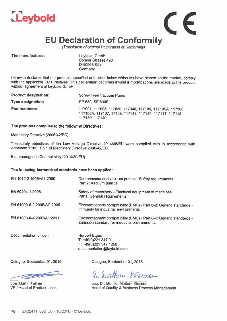
78 GA02411_002_C0 - 10/2016 - © Leybold
EC Declaration of Conformity

79GA02411_002_C0 - 10/2016 - © Leybold

80 GA02411_002_C0 - 10/2016 - © Leybold17200001_002_C0 © Leybold
Declaration of Contamination of Compressors, Vacuum Pumps and Components The repair and / or servicing of compressors, va cuum pumps and components will be carried out only if a correctly completed declaration hasbeen submitted. Non-completion will result in delay. The manufacturer can refuse to accept any equipment without a declaration. A separate declaration has to be completed for each single component.This declaration may be completed and signed only by authorized and qualified staff.
Customer/Dep./Institute : Reason for return: applicable please markAddress : Repair: chargeable warranty Exchange: chargeable warranty Exchange already arranged / received Person to contact: Return only: rent loan for credit Phone : Fax: Calibration: DKD Factory-calibr. End user: Quality test certificate DIN 55350-18-4.2.1
A. Description of the Leybold product: Failure description:
Material description : Catalog number: Additional parts: Serial number: Application-Tool: Type of oil (ForeVacuum-Pumps) : Application- Process:
B. Condition of the equipment No1) Yes No Contamination : No1) Yes
11.. Has the equipment been used toxic 2. Drained (Product/service fluid) corrosive 3. All openings sealed airtight flammable 4. Purged explosive 2)
If yes, which cleaning agent radioactive 2) and which method of cleaning microbiological 2)
1) If answered with “No”, go to D. other harmful substances
C. Description of processed substances (Please fill in absolutely)1. What substances have come into contact with the equipment ?
Trade name and / or chemical term of service fluids and substances processed, properties of the substances According to safety data sheet (e.g. toxic, inflammable, corrosive, radioactive)
X Tradename: Chemical name:
a)
b) c) d)
No Yes2. Are these substances harmful ? 3. Dangerous decomposition products when heated ?
If yes, which ? 2) Components contaminated by microbiological, explosive or radioactive products/substances will not be accepted without written
evidence of decontamination.
D. Legally binding declarationI / we hereby declare that the information supplied on this form is accurate and sufficient to judge any contamination level.
Name of authorized person (block letters) :
Date signature of authorized person
firm stamp

Index
81GA02411_002_C0 - 10/2016 - © Leybold
Index
AAir cooling 26, 37, 38, 47, 59
Ambient temperatures 15, 18, 25, 38, 46, 74, 76
CCastors 7, 27, 32, 35, 37
Condensate 7, 32, 40, 63, 68
Condensate separator 7, 40, 63
Contamination 11, 12, 23, 25, 68, 72, 75, 77
Cooling water 8, 9, 11, 13, 25, 26, 47-49, 59, 64, 69, 76
Cover section 56, 58, 66, 67
Crane eye 7, 29, 34
DDesiccant 13, 29, 36, 40
Dimensional drawing 27, 37
Direction of rotation 6-9, 22, 45, 67
Discharge line 6, 7, 10-12, 26, 37, 40, 59, 75, 76
Dust 12, 14, 17, 18, 20, 32, 40, 63, 68, 70, 73, 75
Dust filter 12, 18, 32, 40, 63, 68, 75
EElectric motor 12, 19, 21, 41
Emergency shutdowns 8, 41
FFan cover 6, 7, 47, 48, 64, 65, 69
Frequency converter 3, 8, 19, 46
Frost 13, 36, 49, 64
GGas ballast 9, 10, 13, 25, 28, 30-32, 50,
54, 55, 59, 61, 63, 64, 70, 73, 75
Gas ballast valve 28, 30, 54, 61, 63, 70
Ground connection 19, 51, 73
HHeat exchanger 23, 46, 47, 64, 69, 74,
76
PPt 100 46
Pumping speed curve 27
Purge gas 6, 9, 10, 13, 18, 21, 29-33, 50, 55, 59, 62, 64, 70, 73, 76
SShaft seal 10, 12, 21, 31
Silencer 7, 11, 26, 32, 35, 40, 59, 68, 73, 75, 76
SP-Guard 18, 25, 28-31, 39, 41, 46-48, 51, 52, 59, 60, 63, 64, 69, 73, 74
Sparks 17, 19, 40
Standstill 53, 60, 64, 66-69, 74, 75
TTemperature class 15, 16
Temperature sensor 25, 42, 44, 46, 50
Thermostatic valve 47, 64, 69
Throttles 33, 70, 71, 72
toppling 34, 35, 37
VVapours 5, 9, 12-14, 16, 17, 23, 40, 60
Vibration 30, 31, 50, 53, 60, 63, 74
WWaste oil 65, 66, 77
Water cooling 26, 31, 47
Water filter 69, 73, 76
Water quality 11, 49
IIgnition risk 11, 16, 17
Ignition Sources 16, 17
Ignition Temperatures 17
Intake line 12, 13, 40, 45, 46, 63, 64, 68, 75
Intake pressure 25, 27, 60
Intake screen 12, 29, 33, 36, 40, 63, 75
JJunction box 41, 44, 45, 57, 59, 75, 76
LLiquid 12, 68
MMedia 5, 9, 12, 21, 28, 29
Motor protection switch 12, 41, 42, 75
NNitrogen 10, 28, 29, 62
Noise 11, 25, 37, 60
Non-return valve 32, 39, 40, 54, 55, 73
OOil 8, 9, 11-13, 23, 25, 29-31, 33, 34,
36, 38, 40, 46, 47, 53, 56, 57, 59, 60, 63, 65-69, 72, 74-77
Oil cooler 13, 30, 34, 38, 46, 47, 63, 67, 68, 76
Oil filter 33, 66, 67
Oil level 18, 30, 31, 50, 56, 57, 63, 66, 67, 74
Oil sight glass 18, 34, 57, 66
Oil temperature 9, 18, 30, 31, 46, 47, 50, 53, 59, 60, 69, 74
Operating temperature 13, 60, 61
Overpressure 6, 7, 9, 18

LVC
orp_
1378
6_20
16
1
0.16
HeadquarterLeybold GmbHBonner Strasse 498D-50968 CologneT: +49-(0)221-347-0F: +49-(0)[email protected]
GermanyLeybold GmbHSales, Service, Support Center (3SC)Bonner Strasse 498D-50968 CologneT: +49-(0)221-347 1234F: +49-(0)221-347 [email protected]
Leybold GmbHSales Area NorthBranch Office BerlinIndustriestrasse 10bD-12099 BerlinT: +49-(0)30-435 609 0F: +49-(0)30-435 609 [email protected]
Leybold GmbHSales Office SouthBranch Office MunichKarl-Hammerschmidt-Strasse 34D-85609 Aschheim-DornachT: +49-(0)89-357 33 9-10F: +49-(0)89-357 33 [email protected]@leybold.com
Leybold Dresden GmbHService Competence CenterZur Wetterwarte 50, Haus 304D-01109 DresdenService:T: +49-(0)351-88 55 00F: +49-(0)351-88 55 [email protected]
Europe
Belgium
Leybold Nederland B.V.Belgisch bijkantoorLeuvensesteenweg 542-9AB-1930 ZaventemSales:T: +32-2-711 00 83F: +32-2-720 83 [email protected]:T: +32-2-711 00 82F: +32-2-720 83 [email protected]
France
Leybold France S.A.S.Parc du Technopolis, Bâtiment Beta3, Avenue du CanadaF-91940 Les Ulis cedexSales and Service:T: +33-1-69 82 48 00F: +33-1-69 07 57 [email protected]@leybold.com
Leybold France S.A.S.Valence Factory640, Rue A. BergèsB.P. 107F-26501 Bourg-lès-Valence CedexT: +33-4-75 82 33 00F: +33-4-75 82 92 [email protected]
Great Britain
Leybold UK LTD.Unit 9Silverglade Business ParkLeatherhead RoadChessingtonSurrey (London)KT9 2QLSales:T: +44-13-7273 7300F: +44-13-7273 [email protected]:T: +44-13-7273 7320F: +44-13-7273 [email protected]
Italy
Leybold Italia S.r.l.Via Trasimeno 8I-20128 MailandSales:T: +39-02-27 22 31F: +39-02-27 20 96 [email protected]:T: +39-02-27 22 31F: +39-02-27 22 32 [email protected]
Netherlands
Leybold Nederland B.V.Floridadreef 102NL-3565 AM UtrechtSales and Service:T: +31-(30) 242 63 30F: +31-(30) 242 63 [email protected]@leybold.com
Switzerland
Leybold Schweiz AG, PfäffikonChurerstrasse 120CH-8808 PfäffikonWarehouse and shipping address:Riedthofstrasse 214CH-8105 RegensdorfSales:T: +41-44-308 40 50F: +41-44-302 43 [email protected]:T: +41-44-308 40 62F: +41-44-308 40 [email protected]
Spain
Leybold Spain, S.A.C/. Huelva, 7E-08940 Cornellà de Llobregat(Barcelona)Sales:T: +34-93-666 43 11F: +34-93-666 43 [email protected]:T: +34-93-666 46 11F: +34-93-685 43 [email protected]
AmericaUSA
Leybold USA Inc.5700 Mellon RoadUSA-Export, PA 15632T: +1-724-327-5700F: [email protected]:T: +1-724-327-5700F: +1-724-333-1217Service:T: +1-724-327-5700F: +1-724-325-3577
Brazil
Leybold do BrasilRod. Vice-Prefeito Hermenegildo Tonolli,nº. 4413 - 6BDistrito IndustrialJundiaí - SPCEP 13.213-086Sales and Service:T: +55 11 3395 3180F: +55 11 99467 [email protected]@leybold.com
AsiaP. R. China
Leybold (Tianjin)International Trade Co. Ltd.Beichen EconomicDevelopment Area (BEDA),No. 8 Western Shuangchen RoadTianjin 300400ChinaSales and Service:T: +86-22-2697 0808F: +86-22-2697 4061F: +86-22-2697 [email protected]@leybold.com
India
Leybold India Pvt Ltd.No. 82(P), 4th PhaseK.I.A.D.B. PlotBommasandra Industrial AreaBangalore - 560 099IndienSales and Service:T: +91-80-2783 9925F: +91-80-2783 [email protected]@leybold.com
Japan
Leybold Japan Co., Ltd.HeadquartersShin-Yokohama A.K.Bldg., 4th floor3-23-3, Shin-YokohamaKohoku-ku, Yokohama-shiKanawaga 222-0033JapanSales:T: +81-45-471-3330F: [email protected]
Leybold Japan Co., Ltd.Tsukuba Technical Service Center1959, Kami-yokobaTsukuba-shi, Ibaraki-shi 305-0854JapanService:T: +81-29 839 5480F: +81-29 839 [email protected]
Malaysia
Leybold MalaysiaLeybold Singapore Pte Ltd.No. 1 Jalan Hi-Tech 2/6Kulim Hi-Tech ParkKulim, Kedah DarulAman 09000MalaysiaSales and Service:T: +604 4020 222F: +604 4020 [email protected]@leybold.com
South Korea
Leybold Korea Ltd.3F. Jellzone 2 TowerJeongja-dong 159-4Bundang-gu Sungnam-siGyeonggi-doBundang 463-384, KoreaSales:T: +82-31 785 1367F: +82-31 785 [email protected]:623-7, Upsung-DongCheonan-SiChungcheongnam-DoKorea 330-290T: +82-41 589 3035F: +82-41 588 [email protected]
Singapore
Leybold Singapore Pte Ltd.8 Commonwealth Lane #01-01Singapore 149555SingaporeSales and Service:T: +65-6303 7030F: +65-6773 [email protected]@leybold.com
Taiwan
Leybold Taiwan Ltd.No 416-1, Sec. 3Chunghsin Rd., ChutungHsinchu County 310Taiwan, R.O.C.Sales and Service:T: +886-3-500 1688F: +886-3-583 [email protected]@leybold.com
Sales and Service