SCREWLINE - Ideal Vacuum
34
SCREWLINE Dry Compressing Screw Vacuum Pump for Industrial Applications DRYVAC Dry Compressing Screw Vacuum Pump CHEMROVAC Dry Vacuum Pump for Chemical and Pharmaceutical Applications 171.06.02 Excerpt from the Oerlikon Leybold Vacuum Full Line Catalog Product Section C05 Edition January 2011
Transcript of SCREWLINE - Ideal Vacuum

SCREWLINEDry Compressing Screw Vacuum Pumpfor Industrial Applications
DRYVACDry Compressing Screw Vacuum Pump
CHEMROVACDry Vacuum Pumpfor Chemical and Pharmaceutical Applications
171.06.02Excerpt from the Oerlikon Leybold Vacuum Full Line CatalogProduct Section C05Edition January 2011

C05
Contents
Global Versions
Product SCREWLINE
Applications . . . . . . . . . . . . . . . . . . . . . . . . . . . . . . . . . . . . . . . . . . . . . . . . . . . . . . . . . . . . . . . . . . . . . . . C05.03
General . . . . . . . . . . . . . . . . . . . . . . . . . . . . . . . . . . . . . . . . . . . . . . . . . . . . . . . . . . . . . . . . . . . . . . . . . . C05.04
Products
SCREWLINE SP250 . . . . . . . . . . . . . . . . . . . . . . . . . . . . . . . . . . . . . . . . . . . . . . . . . . . . . . . . . . . . . . . . C05.08
SCREWLINE SP630 . . . . . . . . . . . . . . . . . . . . . . . . . . . . . . . . . . . . . . . . . . . . . . . . . . . . . . . . . . . . . . . . C05.11
Accessories
SP-GUARD . . . . . . . . . . . . . . . . . . . . . . . . . . . . . . . . . . . . . . . . . . . . . . . . . . . . . . . . . . . . . . . . . . . . . . . C05.16
Miscellaneous
Vacuum Pump Oils. . . . . . . . . . . . . . . . . . . . . . . . . . . . . . . . . . . . . . . . . . . . . . . . . . . . . . . . . . . . . . . . . . C05.17
Maintenance Kit for changing the Gear Oil . . . . . . . . . . . . . . . . . . . . . . . . . . . . . . . . . . . . . . . . . . . . . . . . C05.17
Product DRYVAC
Application . . . . . . . . . . . . . . . . . . . . . . . . . . . . . . . . . . . . . . . . . . . . . . . . . . . . . . . . . . . . . . . . . . . . . . . . C05.18
Products
DRYVAC enduro / sprinter/ champion . . . . . . . . . . . . . . . . . . . . . . . . . . . . . . . . . . . . . . . . . . . . . . . . . . . C05.26
Versions for the North and South American Continents
Product CHEMROVAC AMR
Application . . . . . . . . . . . . . . . . . . . . . . . . . . . . . . . . . . . . . . . . . . . . . . . . . . . . . . . . . . . . . . . . . . . . . . . . C05.28
General . . . . . . . . . . . . . . . . . . . . . . . . . . . . . . . . . . . . . . . . . . . . . . . . . . . . . . . . . . . . . . . . . . . . . . . . . . C05.28
Products
CHEMROVAC AMR 70 to 550 . . . . . . . . . . . . . . . . . . . . . . . . . . . . . . . . . . . . . . . . . . . . . . . . . . . . . . . . C05.30
02 Oerlikon Leybold Vacuum Full Line Catalog
C0503Oerlikon Leybold Vacuum Full Line Catalog
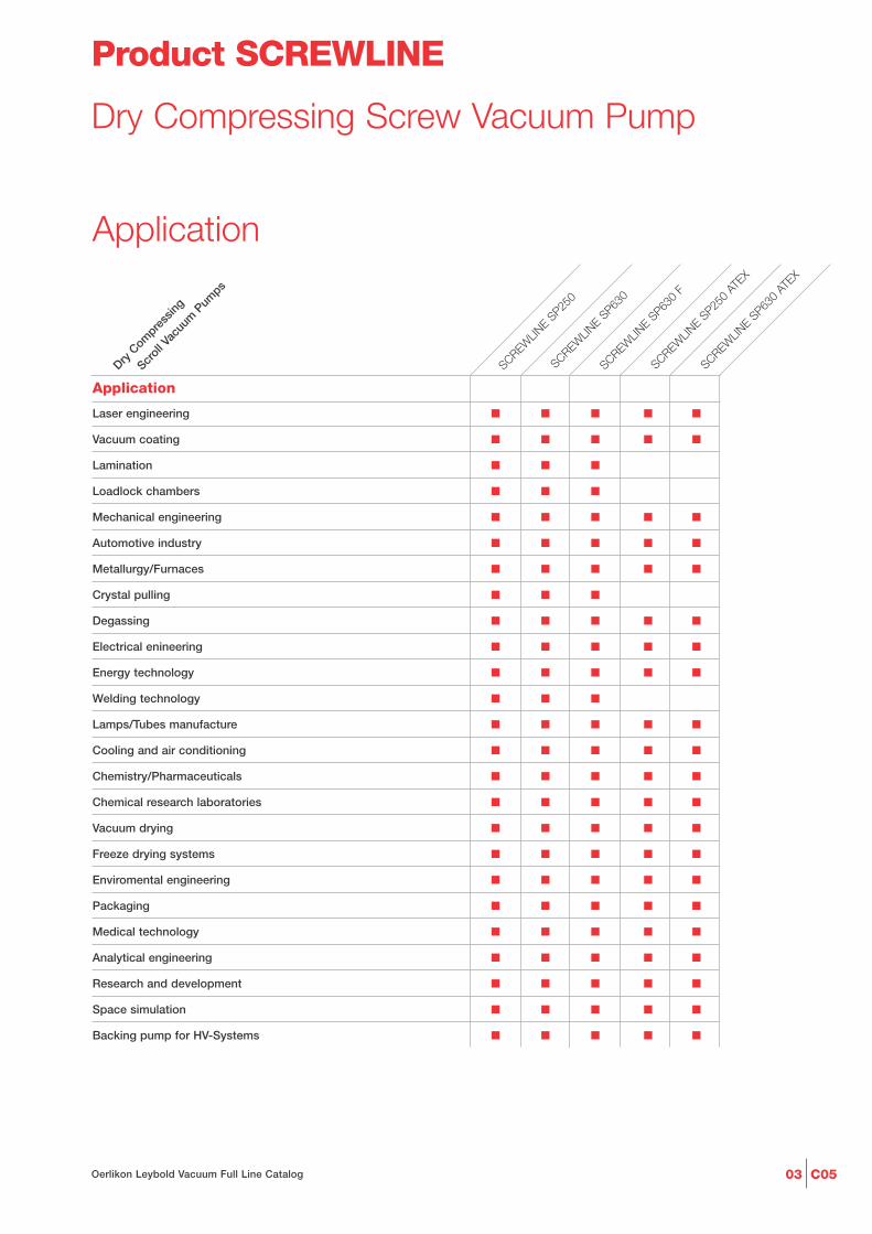
Product SCREWLINE
Dry Compressing Screw Vacuum Pump
Application
Laser engineering ■ ■ ■ ■ ■
Vacuum coating ■ ■ ■ ■ ■
Lamination ■ ■ ■
Loadlock chambers ■ ■ ■
Mechanical engineering ■ ■ ■ ■ ■
Automotive industry ■ ■ ■ ■ ■
Metallurgy/Furnaces ■ ■ ■ ■ ■
Crystal pulling ■ ■ ■
Degassing ■ ■ ■ ■ ■
Electrical enineering ■ ■ ■ ■ ■
Energy technology ■ ■ ■ ■ ■
Welding technology ■ ■ ■
Lamps/Tubes manufacture ■ ■ ■ ■ ■
Cooling and air conditioning ■ ■ ■ ■ ■
Chemistry/Pharmaceuticals ■ ■ ■ ■ ■
Chemical research laboratories ■ ■ ■ ■ ■
Vacuum drying ■ ■ ■ ■ ■
Freeze drying systems ■ ■ ■ ■ ■
Enviromental engineering ■ ■ ■ ■ ■
Packaging ■ ■ ■ ■ ■
Medical technology ■ ■ ■ ■ ■
Analytical engineering ■ ■ ■ ■ ■
Research and development ■ ■ ■ ■ ■
Space simulation ■ ■ ■ ■ ■
Backing pump for HV-Systems ■ ■ ■ ■ ■
Dry C
ompre
ssing
Scroll V
acuu
m P
umps
SCREWLIN
E SP25
0
SCREWLIN
E SP63
0
Application
SCREWLIN
E SP63
0 AT
EX
SCREWLIN
E SP25
0 AT
EX
SCREWLIN
E SP63
0 F

C05 04 Oerlikon Leybold Vacuum Full Line Catalog
Principle of Operation
SCREWLINE vacuum pumps are drycompressing backing pumps, the ope-ration of which is based on the screwprinciple. The pumping chamber of thepump is formed by two synchronisedpositive displacement rotors and thehousing enclosing these. Since therotors rotate in opposite directions, thechambers move steadily from the in-take to the exhaust side of the pumpsthereby resulting in a smooth pumpingaction (see figure below). Since with asingle SCREWLINE rotor pair a multi-stage compression process is imple-mented, the component count in thepumping path is very low. In this waymaintenance and servicing work ismuch simplified.
Properties
The direct pumping path without mul-tiple deflections for the medium makethe SCREWLINE vacuum pumps highlyinsensitive to foreign materials. Thisensures a high uptime in industrial pro-cesses.
The two non-contacting shaft-seals arepractically wear-free, which allows forvery long maintenance intervals.
For standard applications no purgegas is required. However, a purge gassupply can be connected as an optionto purge the seals, should the applica-tion process require this.
Because of the cantilevered bearingarrangement for the SCREWLINErotors, a potential source of failure (i.e.a bearing on the intake side) is entirelyeliminated. On the one hand, no lubri-cants from the bearings can enter intothe vacuum process, and the otherhand also an impairment of the bearingby aggressive process media can beexcluded.
A further benefit of the cantileveredbearing arrangement is the easyaccessibility of the pump chamber.This innovative design feature allowsthe removal of the pump housing with
out time-consuming and costly disas-sembly of the bearings. Thus on-sitecleaning of all surfaces in contact withthe medium is possible. In particular, ifthe processes involved considerableamounts of contaminants this is a sig-nificant advantage which ensures along uptime.
Besides the integrated oil coolingarrangement for the rotors, the SCREWLINE pumps are air-cooledfrom the outside. Here rotor and hou-sings are thermally linked via the oilcooler. Thus, SCREWLINE pumpsadapt themselves ideally to the am-bient conditions under changing ope-rating situations.
Pump chamberhousing
Direction of pumping action
Direction ofrotation
Rotors
Principle of operation of the SCREWLINE pumps
General
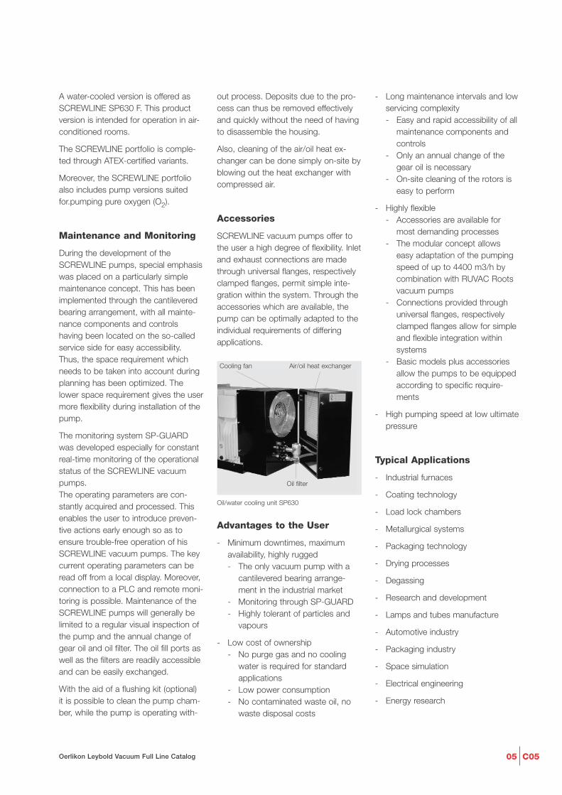
Oil/water cooling unit SP630 F
The SCREWLINE pumps were develo-ped in view of the special requirementsof industrial applications. The innovati-ve design allows these pumps to beused whenever reliable, compact andlow maintenance vacuum solutions arerequired.
Pump system SCREWLINE SP630 with RUVAC WAU 2001
C0505Oerlikon Leybold Vacuum Full Line Catalog
out process. Deposits due to the pro-cess can thus be removed effectivelyand quickly without the need of havingto disassemble the housing.
Also, cleaning of the air/oil heat ex-changer can be done simply on-site byblowing out the heat exchanger withcompressed air.
Accessories
SCREWLINE vacuum pumps offer tothe user a high degree of flexibility. Inletand exhaust connections are madethrough universal flanges, respectivelyclamped flanges, permit simple inte-gration within the system. Through theaccessories which are available, thepump can be optimally adapted to theindividual requirements of differingapplications.
- Long maintenance intervals and lowservicing complexity- Easy and rapid accessibility of all
maintenance components and controls
- Only an annual change of the gear oil is necessary
- On-site cleaning of the rotors is easy to perform
- Highly flexible- Accessories are available for
most demanding processes- The modular concept allows
easy adaptation of the pumping speed of up to 4400 m3/h by combination with RUVAC Roots vacuum pumps
- Connections provided through universal flanges, respectively clamped flanges allow for simple and flexible integration within systems
- Basic models plus accessories allow the pumps to be equipped according to specific require-ments
- High pumping speed at low ultimatepressure
Typical Applications
- Industrial furnaces
- Coating technology
- Load lock chambers
- Metallurgical systems
- Packaging technology
- Drying processes
- Degassing
- Research and development
- Lamps and tubes manufacture
- Automotive industry
- Packaging industry
- Space simulation
- Electrical engineering
- Energy research
A water-cooled version is offered asSCREWLINE SP630 F. This productversion is intended for operation in air-conditioned rooms.
The SCREWLINE portfolio is comple-ted through ATEX-certified variants.
Moreover, the SCREWLINE portfolioalso includes pump versions suitedfor.pumping pure oxygen (O2).
Maintenance and Monitoring
During the development of the SCREWLINE pumps, special emphasiswas placed on a particularly simplemaintenance concept. This has beenimplemented through the cantileveredbearing arrangement, with all mainte-nance components and controlshaving been located on the so-calledservice side for easy accessibility.Thus, the space requirement whichneeds to be taken into account duringplanning has been optimized. Thelower space requirement gives the usermore flexibility during installation of thepump.
The monitoring system SP-GUARDwas developed especially for constantreal-time monitoring of the operationalstatus of the SCREWLINE vacuumpumps.The operating parameters are con-stantly acquired and processed. Thisenables the user to introduce preven-tive actions early enough so as toensure trouble-free operation of hisSCREWLINE vacuum pumps. The keycurrent operating parameters can beread off from a local display. Moreover,connection to a PLC and remote moni-toring is possible. Maintenance of theSCREWLINE pumps will generally belimited to a regular visual inspection ofthe pump and the annual change ofgear oil and oil filter. The oil fill ports aswell as the filters are readily accessibleand can be easily exchanged.
With the aid of a flushing kit (optional) it is possible to clean the pump cham-ber, while the pump is operating with-
Oil/water cooling unit SP630
Air/oil heat exchangerCooling fan
Oil filter
Advantages to the User
- Minimum downtimes, maximum availability, highly rugged- The only vacuum pump with a
cantilevered bearing arrange-ment in the industrial market
- Monitoring through SP-GUARD- Highly tolerant of particles and
vapours
- Low cost of ownership- No purge gas and no cooling
water is required for standard applications
- Low power consumption- No contaminated waste oil, no
waste disposal costs

C05 06 Oerlikon Leybold Vacuum Full Line Catalog
a
h4
h1h
h 2
l 3l 2
l 1l
l 4
h 3
b 2b 3
b
b 1
a
> 900distance for maintenance
a
Dimensional drawing for the SCREWLINE SP250
a b b1 b2 b3
mm > 500 450 268 470 510in. > 19.69 17.72 10.55 18.50 20.08
h h1 h2 h3 h4
mm 646 385 746 100 68 - 75in. 25.43 15.16 29.37 3.94 2.68 - 2.95
l l1 l2 l3 l4
mm 1348 880 529 156 236in. 53.08 34.65 20.83 6.14 9.29
a
a
b 4
h 1
h 2
h 3
h 4
l
l 1
l 5l 6
h5
l 4 l 3
l 2
a 1
b 2
b
h
b 3
b 1
> 900distance for maintenance
l7
Dimensional drawing for the SCREWLINE SP630
a a1 b b1 b2 b3 b4
mm > 500 > 300 555 470 276 380 439in. > 19.69 > 11.81 21.85 18.50 10.87 14.96 17.28
h h1 h2 h3 h4 h5 l
mm 806 636 698 450 248 68 1220in. 31.73 25.04 27.48 17.72 9.76 2.68 48.03
l1 l2 l3 l4 l5 l6 l7
mm 1626 703 880 157 514 189 250in. 64.02 27.68 34.65 6.18 20.24 7.44 9.84
C0507Oerlikon Leybold Vacuum Full Line Catalog
Pressure mbar
0
100
200
300
400
P
um
pin
g S
pee
d
m3/h
10-3 10-2 10-1 100 101 102 103
SP250 (50 Hz)
SP250 (60 Hz)
10-1 1 10 Torr 75010-210-3
200
cfm
50
100
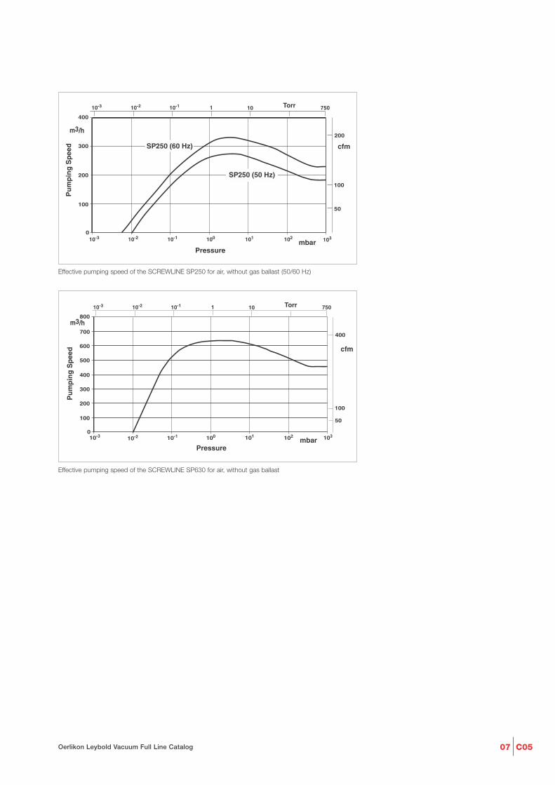
Effective pumping speed of the SCREWLINE SP250 for air, without gas ballast (50/60 Hz)
10-20
100
200
300
400
500
600
700
800
10-3 10-1 100 101 102 103
Pressure mbar
Pu
mp
ing
Sp
eed
m3/h
10-1 1 10 Torr 75010-210-3
400
cfm
50
100
Effective pumping speed of the SCREWLINE SP630 for air, without gas ballast
C05 08 Oerlikon Leybold Vacuum Full Line Catalog
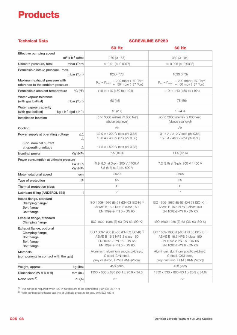
Technical Data SCREWLINE SP250
50 Hz 60 HzEffective pumping speed
m3 x h-1 (cfm)
Ultimate pressure, total mbar (Torr)
Permissible intake pressure, max.mbar (Torr)
Maximum exhaust pressure with reference to the ambient pressure
Permissible ambient temperature °C (°F)
Water vapour tolerance (with gas ballast) mbar (Torr)
Water vapour capacity (with gas ballast) kg x h-1 (gal x h-1)
Installation location
Cooling
Power supply at operating voltage VVV
3-ph. nominal current at operating voltage V
Nominal power kW (HP)
Power consumption at ultimate pressurekW (HP)kW (HP)
Motor rotational speed rpm
Type of protection IP
Thermal protection class
Lubricant filling (ANDEROL 555) l
Intake flange, standardClamping flangeBolt flangeBolt flange
Exhaust flange, standardClamping flange
Exhaust flange, optionalClamping flangeBolt flangeBolt flangeBolt flange
Materials (components in contact with the gas)
Weight, approx. kg (lbs)
Dimensions (W x D x H) mm (in.)
Noise level 2) dB(A)
1) This flange is required when ISO-K flanges are to be connected (Part No. 267 47)2) With connected exhaust gas line at ultimate pressure (in acc. with ISO 4871)
270 (≥ 157) 330 (≥ 194)
� 0.01 (� 0.0075) � 0.005 (� 0.0038)
1030 (773) 1030 (773)
+ 200 mbar (150 Torr) + 200 mbar (150 Torr)pex = pamb pex = pamb– 050 mbar (037 Torr) – 050 mba (037 Torr)
+10 to +40 (+50 to +104) +10 to +40 (+50 to +104)
60 (45) 75 (56)
10 (2.7) 18 (4.9)
up to 3000 metres (9.800 feet) up to 3000 metres (9.800 feet)(above sea level) (above sea level)
Air Air
32.0 A / 200 V (cos phi 0.88) 31.5 A / 210 V (cos phi 0.88)16.0 A / 400 V (cos phi 0.88) 15.5 A / 460 V (cos phi 0.88)
14.5 A / 500 V (cos phi 0.88) –
7.5 (10.0) 11.5 (15.6)
5.9 (8.0) at 3-ph. 200 V / 400 V 7.2 (9.8) at 3-ph. 200 V / 400 V6.5 (8.8) at 3-ph. 500 V –
2920 3505
55 55
F F
7 7
ISO 1609-1986 (E)-63 (DN 63 ISO-K) 1) ISO 1609-1986 (E)-63 (DN 63 ISO-K) 1)
ASME B 16.5 NPS 3 class 150 ASME B 16.5 NPS 3 class 150EN 1092-2-PN 6 - DN 65 EN 1092-2-PN 6 - DN 65
ISO 1609-1986 (E)-63 (DN 63 ISO-K) ISO 1609-1986 (E)-63 (DN 63 ISO-K)
ISO 1609-1986 (E)-63 (DN 63 ISO-K) 1) ISO 1609-1986 (E)-63 (DN 63 ISO-K) 1)
ASME B 16.5 NPS 3 class 150 ASME B 16.5 NPS 3 class 150EN 1092-2-PN 16 - DN 65 EN 1092-2-PN 16 - DN 65EN 1092-2-PN 6 - DN 65 EN 1092-2-PN 6 - DN 65
Aluminum, aluminum anodic oxidised, Aluminum, aluminum anodic oxidised,C steel, CrNi steel, C steel, CrNi steel,
grey cast-iron, FPM (FKM) ((Viton)) grey cast-iron, FPM (FKM) ((Viton))
450 (992) 450 (992)
1350 x 530 x 880 (53.1 x 20.9 x 34.6) 1350 x 530 x 880 (53.1 x 20.9 x 34.6)
67 72
Products

C0509Oerlikon Leybold Vacuum Full Line Catalog
Ordering Information
SCREWLINE SP250 (50/60 Hz)with SP-GUARD
and manual gas ballastwith SP-GUARD and
electromagnetic gas ballastwith manual gas ballastwith electromagnetic gas ballastwith SP-GUARD, purge gas unit, castors
and manual gas ballast valvewith SP-GUARD,
electromagnetic gas ballastand purge gas unitCategory 3GD IIC 160 °C inside
with SP-GUARD, special gaskets, electromagnetic gas ballast and purge gas unitCategory 3GD IIC 160 °C inside
with SP-GUARD, electromagnetic gas ballast and purge gas unitCategory 3GD IIC 160 °C inside /Category 3GD Ex nA IIC 160 °C outside
with SP-GUARD, electromagnetic gas ballast and purge gas unitCategory 2G3D b IIC 135 °C inside /Category 3GD Ex nA IIC 160 °C outside(50 Hz only)
with SP-GUARD, electromagnetic gas ballast Purge vent vit,FFPM gaskets and purge gas unitCategory 2G3D b IIC 135 °C inside /Category 3GD Ex nA IIC 160 °C outside(50 Hz only)
Category 2Gb IIC T4 3D T 130 °C X inside /Category 2Gb IIC T4 3D T 130 °C X outsideelectropneumatic gas ballast, sensors,wired including junction box, purge gas unit (3-ph. only, 500 V, 50 Hz; DN 65 PN 16) 2)
1) ATEX Category 3 as standard (Directive 94/9/EG)+ 200 mbar2) T4 with max. pex = pamb + 050 mbar
For all enquiries and orders relating to category 1 and 2 ATEX products please exclusively use our ATEX questionnaire. You can find this questionnaire at the end of the full-line catalog together with the fax forms or in the Internet under “www.oerlikon.com/leyboldvacuum” under Download Documents in the area Documentation.
SCREWLINE SP250Standard ATEX O2
Part No. Part No. Part No.
115 001 – –
115 002 – –115 004 – –115 005 – –
115 006 – –
– 115 003 1) –
– 115 009 –
– 115 010 –
– 115 011 –
– 115 012V –
– – 115 019
C05 10 Oerlikon Leybold Vacuum Full Line Catalog
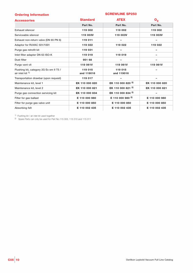
Ordering Information
Accessories
Exhaust silencer
Serviceable silencer
Exhaust non-return valve (DN 65 PN 6)
Adaptor for RUVAC 501/1001
Purge gas retrofit kit
Inlet filter adapter DN 63 ISO-K
Dust filter
Purge vent vit
Flushing kit, category 2G Ex em II T5 / air inlet kit 1)
Transportation drawbar (upon request)
Maintenance kit, level 1
Maintenance kit, level 2
Purge gas connection servicing kit
Filter for gas ballast
Filter for purge gas valve unit
Absorbing felt
1) Flushing kit / air inlet kit used together2) Spare Parts can only be used for Part No.115 003, 115 010 and 115 011
SCREWLINE SP250
Standard ATEX O2
Part No. Part No. Part No.
119 002 119 002 119 002
119 003V 119 003V 119 003V
119 011 – –
119 022 119 022 119 022
119 031 – –
119 019 119 019 –
951 68 – –
119 061V 119 061V 119 061V
119 015 119 015 –and 119016 and 119016
119 017 – –
EK 110 000 820 EK 110 000 820 2) EK 110 000 820
EK 110 000 821 EK 110 000 821 2) EK 110 000 821
EK 110 000 834 EK 110 000 834 2) –
E 110 000 980 E 110 000 980 2) E 110 000 980
E 110 000 850 E 110 000 850 E 110 000 850
E 110 002 435 E 110 002 435 E 110 002 435

C0511Oerlikon Leybold Vacuum Full Line Catalog
Technical DataSCREWLINE SP630
50 Hz 60 HzPumping speed
m3 x h-1 (cfm)
Ultimate total pressure mbar (Torr)
Maximum exhaust pressure with reference to the ambient pressure
Intake pressure limits, max. mbar (Torr)
Permissible ambient temperature °C (°F)
Water vapour tolerance (with gas ballast) mbar (Torr)
Water vapour capacity (with gas ballast) kg x h-1 (gal x h-1)
Installation location
Cooling
Power supply VVV
cos ff
Nominal power kW (HP)
Power consumption at ultimate pressurekW (HP)
Motor rotational speed rpm
Type of protection IP
Thermal protection class
Lubricant filling (ANDEROL 555) l
Intake flange and exhaust flange compatible with bolt flanges
Materials (components in contact with the gas)
Weight, approx. kg (lbs)
Dimensions (W x D x H) mm (in.)
Noise level 2) dB(A)
1) This flange is required when ISO-K flanges are to be connected (P/N 267 50)2) With connected exhaust gas line at ultimate pressure (in acc. with ISO 4871)
630 (371) 630 (371)
� 0.01 (� 0.0075) � 0.01 (� 0.0075)
+ 200 mbar (150 Torr) + 200 mbar (150 Torr)pex = pamb pex = pamb– 050 mbar (037 Torr) – 050 mbar (037 Torr)
1030 (773) 1030 (773)
+10 to +40 (+50 to +104) +10 to +40 (+50 to +104)
40 (30) 40 (30)
14 (3.7) 14 (3.7)
up to 3000 metres (9.800 feet) up to 3000 metres (9.800 feet)(above sea level) (above sea level)
Air Air
56 A / 200 V 52 A / 210 V28 A / 400 V 24 A / 460 V
0.89 0.90
15 (20) 15 (20)
< 11 (< 15) < 11 (< 15)
2930 3530
55 55
F F
15 15
EN 1092-2 - PN 6 - DN 100 EN 1092-2 - PN 6 - DN 100EN 1092-2 - PN 16 - DN 100 EN 1092-2 - PN 16 - DN 100
ISO 1609-1986 (E)-100 (DN 100 ISO-K) 1) ISO 1609-1986 (E)-100 (DN 100 ISO-K) 1)
ASME B 16.5 NPS4 class 150 ASME B 16.5 NPS4 class 150
Aluminum, alumnium anodic oxidised, Aluminum, alumnium anodic oxidised,C steel, CrNi steel, C steel, CrNi steel,
grey cast-iron, FPM (FKM) ((Viton)) grey cast-iron, FPM (FKM) ((Viton))
530 (1166) 530 (1166)
1630 x 660 x 880 (64 x 26 x 35) 1630 x 660 x 880 (64 x 26 x 35)
73 75
Additional Technical DataSCREWLINE SP630 F
50 Hz 60 HzCooling
Water connection G
Water temperature °C (°F)
Minimum water feed pressurebar (psi, gauge)
Nominal flow at a water feed temperature of 25° C (77 °F) l/min (gal/min)
Noise level 1) dB(A)
1) With connected exhaust gas line at ultimate pressure (in acc. with ISO 4871)
Water Water
1/2" ISO 228-1 1/2" ISO 228-1
+5 to +35 (+41 to +95) +5 to +35 (+41 to +95)
2 (15) 2 (15)
12 (3) 12 (3)
71 71

C05 12 Oerlikon Leybold Vacuum Full Line Catalog
Ordering Information
SCREWLINE SP630
air cooled,
with adapter for RUVAC 2001, SP-GUARD
and electromagnetic gas ballast
with SP-GUARD and manual gas ballast
with SP-GUARD and
electromagnetic gas ballast
with adaptor for RUVAC 2001, SP-GUARD
and manual gas ballast
with electromagnetic gas ballast
with manual gas ballast
SCREWLINE SP630 F
water cooled,
with adapter for RUVAC 2001, SP-GUARD
and electromagnetic gas ballast
with adapter for RUVAC 2001, SP-GUARD
and manual gas ballast
50 Hz
with SP-GUARD and manual gas ballast
with SP-GUARD, purge gas kit
and manual gas ballast
SCREWLINE SP630 S1
water cooled,
with adapter for RUVAC 2001, castors,
SP-GUARD, purge gas kit
and electromagnetic gas ballast
SCREWLINE SP630 FK
water cooled,
with adapter for RUVAC 1001, castors,
SP-GUARD, purge gas kit
and electromagnetic gas ballast
SCREWLINE SP630/SP630 F
50 Hz 60 HzPart No. Part No.
117 005 117 006
117 007 117 008
117 009 117 010
117 011 117 012
117 021 117 022
117 023 117 024
117 105 117 106
117 109 –
117 107 117 108
117 113 117 114
117 117 117 118
117 125 –

C0513Oerlikon Leybold Vacuum Full Line Catalog
Ordering Information
Accessories
Exhaust silencer
Serviceable silencer
Silencer kit
Water connection accessories
for Part No. 119 005V0
Roots pump adapter
for RUVAC 1001 1)
for RUVAC 2001
für RUVAC WH 2500
für RUVAC WH 4400
Dust filter 2)
Elbow 90° (DN 100 ISO-K)
Clamping screws for DN 63-250 ISO-K
Centering ring for DN 100 ISO-K
Purge vent Kit
Inlet filter adapter DN 100 ISO-K
Gas ballast, manual
Gas ballast, 24 V DC (DN 16 KF) 3)
SP-GUARD kit, complete 4)
Non-return valve (DN 100 PN 6)
Purge gas retrofit kit 3)
Flushing kit, category 2G Ex em II T5 /
air inlet kit 5)
Transportation drawbar for
Part No. 117 117 / 117 118
Maintenance kit, level 1
up to serial number 31000197911
from serial number 31000197911
Maintenance kit, level 2
Purge gas connection servicing kit
Filter for gas ballast
Filter for purge gas valve unit
Water filter maintenance kit for SP630 F
1) Must mount to adapter Part No. 119 0212) For information on the dust filter please refer to the Product Section C02, Section "Accessories”3) Not for ATEX pumps4) Can only be installed as a service provided by Oerlikon Leybold Vacuum5) Flushing kit / air inlet kit used together
SCREWLINE SP630 / SP630 F Standard
50 Hz 60 HzPart No. Part No.
119 001 119 001
119 004V 119 004V
119 005V0 119 005V0
119 006V0 119 006V0
500 003 173 500 003 173
119 021 119 021
115 222V 115 222V
119 024V 119 024V
951 72 951 72
887 26 887 26
267 01 267 01
268 06 268 06
119 060V 119 0600V
119 020 119 020
119 051 119 051
119 052 119 052
EK 110 000 809 EK 110 000 809
119 010 119 010
119 030 119 030
119 015 119 015
and 119 016 and 119 016
119 017 Part No. 119 017
EK 110 000 792 EK 110 000 792
EK 110 000 832 EK 110 000 832
EK 110 000 793 EK 110 000 793
EK 110 000 827 EK 110 000 827
E 110 000 980 E 110 000 980
E 110 000 850 E 110 000 850
EK 110 000 813 EK 110 000 813

C05 14 Oerlikon Leybold Vacuum Full Line Catalog
Ordering Information
SCREWLINE SP630
with SP-GUARD, purge gas kit
and manual gas ballast
Category 3G IIC (160 °C) inside
with SP-GUARD, purge gas kit
and electromagnetic gas ballast
Category 3G IIC (160 °C) inside
SCREWLINE SP630 F, water cooled
Category 2G3D IIC (160 °C)
Category 3G IIC T3 (160 °C)
with purge gas monitor,
SP-GUARD, adapter for RUVAC 2001
and electromagnetic gas ballast
Category 3G IIC 160 °C inside
SP-GUARD, purge gas kit
and electromagnetic gas ballast
Exhaust silencer
Roots pump adapter
for RUVAC 1001 1)
for RUVAC 2001
Inlet filter adapter DN 100 ISO-K
Non-return valve (DN 100 PN 6)
Flushing kit, category 2G Ex em II T5 /
air inlet kit 2)
Maintenance kit, level 1
up to serial number 31000197911
from serial number 31000197911
Maintenance kit, level 2
Purge gas connection servicing kit
Filter for gas ballast
Water filter maintenance kit for SP630 F
SCREWLINE SP630 / SP630 F ATEX
50 Hz 60 HzPart No. Part No.
117 017 117 018
117 019 117 020
117 111 117 112
117 115 117 116
119 001 119 001
500 003 173 500 003 173
119 021 119 021
119 020 119 020
119 010 119 010
119 015 119 015
and 119 016 and 119 016
EK 110 000 792 EK 110 000 792
EK 110 000 832 EK 110 000 832
EK 110 000 793 EK 110 000 793
EK 110 000 827 EK 110 000 827
E 110 000 980 E 110 000 980
EK 110 000 813 EK 110 000 813

C0515Oerlikon Leybold Vacuum Full Line Catalog
Ordering Information
SCREWLINE SP630
with SP-GUARD, purge gas monitor
and electromagnetic gas ballast
Exhaust silencer
Roots pump adapter
for RUVAC 1001 1)
for RUVAC 2001
Maintenance kit, level 1
up to serial number 31000197911
from serial number 31000197911
Maintenance kit, level 2
Purge gas connection servicing kit
Filter for gas ballast
Filter for purge gas valve unit
1) Must mount to adapter Part No. 119 0212) Flushing kit / air inlet kit used together
For all enquiries and orders relating to category 1 and 2 ATEX products please exclusively use our ATEX questionnaire. You can find this questionnaire at the end of the full-line catalog together with the fax forms or in the Internet under “www.oerlikon.com/leyboldvacuum” under Download Documents in the area Documentation.
SCREWLINE SP630 O2
50 Hz 60 HzPart No. Part No.
117 039 117 040
119 001 119 001
500 003 173 500 003 173
119 021 119 021
EK 110 000 792 EK 110 000 792
EK 110 000 832 EK 110 000 832
EK 110 000 793 EK 110 000 793
EK 110 000 827 EK 110 000 827
E 110 000 980 E 110 000 980
E 110 000 850 E 110 000 850
C05 16 Oerlikon Leybold Vacuum Full Line Catalog
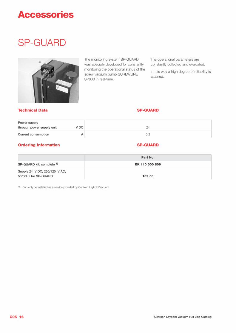
SP-GUARD
Technical Data SP-GUARD
Power supply
through power supply unit V DC
Current consumption A
24
0.2
Ordering Information
Part No.
EK 110 000 809
152 50
SP-GUARD kit, complete 1)
Supply 24 V DC, 230/120 V AC,
50/60Hz for SP-GUARD
1) Can only be installed as a service provided by Oerlikon Leybold Vacuum
SP-GUARD
The monitoring system SP-GUARDwas specially developed for constantlymonitoring the operational status of thescrew vacuum pump SCREWLINE SP630 in real-time.
The operational parameters areconstantly collected and evaluated.
In this way a high degree of reliability isattained.
Accessories

C0517Oerlikon Leybold Vacuum Full Line Catalog
Vacuum Pump Oils
The vacuum pump oil Anderol 555 de-tailed below was qualified for usage inthe SCREWLINE line of pumps througha comprehensive series of experimentsunder application conditions in ourown factory laboratories.
Lubricating oils for vacuum pumpsmust meet tough requirements. Theyneed to have excellent lubricating pro-perties and resistant against thermaldecomposition and increased mecha-nical stress.
Safety data sheets are available to professional users from:E.mail “[email protected]” or Internet “www.oerlikon.com/leyboldvacuum”.
Application Data ANDEROL 555
Type of oil Diester oil
Our oils are subjected to an involvedqualification process with respect totheir technical suitability in our vacuumpumps.Our warranty commitment is depen-dent on the usage of lubricating oilswhich are qualified by us.No liability will be assumed for anydamage caused by the use of types ofoil which have not been qualified orwhich are unsuitable.
Miscellaneous
Ordering Information
Part No. EK
EK 110 000 820
EK 110 000 792
EK 110 000 832
EK 110 000 793
EK 110 000 794
EK 200 10 272EK 200 10 891EK 200 00 193
Maintenance kit stage 1SP250 for changing the gear oil
ANDEROL 555,oil filter cartridge and gaskets
SP630 for changing the gear oilup to serial number 31000197911ANDEROL 555,oil filter cartridge BG30and 2 gaskets
from serial number 31000197911ANDEROL 555,oil filter cartridge BG60and 2 gaskets
Maintenance kit level 2SP630 for pump chamber inspection,2 O-rings, inlet screen including O-rings
Maintenance kit level 3SP630 for axial bearing replacement,2 O-rings, 6 gaskets (Cu),2 angular contact ball bearings
Oil ANDEROL 55501 liter (1.1 qt)05 liters (5.3 qt)20 liters (21.1 qt)
Maintenance Kitfor changing the Gear Oil

C05 18 Oerlikon Leybold Vacuum Full Line Catalog
Packaging
Automotive industry
Vacuum drying
Electrical components
Energy technology
Degassing
Lamination
Industrial gases
Wind turbines
Leak testing machines
Load lock chambers
Metallurgy/Furnaces
Crystal growing
Welding technology
Refrigeration and air conditioning
Plasma cleaning or activation
Sterilazition
Freeze drying
Vacuum coating
Research and development
Space simulation
Backing pump for
Highvacuum systems
Pumps
DRYVAC e
ndur
o65
0 S
DRYVAC sp
rinte
r65
0 S
DRYVAC sp
rinte
r65
0 S-i
DRYVAC c
ham
pion
650
S
DRYVAC c
ham
pion
650
S-r
DRYVAC c
ham
pion
5000
RS-i
■ ■
■ ■
■ ■ ■ ■
■ ■
■ ■ ■ ■ ■ ■
■ ■
■ ■ ■ ■ ■ ■
■ ■ ■ ■
■ ■
■ ■ ■ ■
■ ■
■ ■
■ ■ ■ ■ ■ ■
■ ■ ■ ■
■ ■
■ ■ ■ ■ ■ ■
■ ■ ■ ■
■ ■ ■ ■ ■ ■
■ ■ ■ ■
■ ■ ■ ■ ■ ■
■ ■
■ ■
Applications
DRYVAC c
ham
pion
650
S-i
DRYVAC e
ndur
o65
0 S-r
Application
Product DRYVACDry Compressing Screw Vacuum Pump

C0519Oerlikon Leybold Vacuum Full Line Catalog
DRYVAC enduro / sprinter/ champion650 S, 650 S-r, 650 S-i and 5000 RS-i
The Benefits of the ScrewPrinciple
The direct pumping path without multi-ple deflections of the gas makes theDRYVAC vacuum pumps very insensi-tive to foreign materials. This ensures ahigh reliability in industrial processes.The straight and short path for the gasfrom the inlet of the pump to its ex-haust reduces the dwell time of thegas and thereby reduces potential de-posits within the pump. Through theuse of a purge gas (e.g. gas ballast),any deposits, particles and conden-sates can be effectively removed.
DRYVAC series
DRYVAC is a new family of dry com-pressing screw vacuum pumps availa-ble with different features dependingon the specific application. TheDRYVAC family was developed in con-sideration of the special requirementsof the photovoltaic, display and pro-cess industries. All DRYVAC variantsare water cooled, very compact andeasy to combine into systems, in parti-cular with the well-proven Rootspumps of the RUVAC WH, WS andWA series.
Just like the SCREWLINE, theDRYVAC was developed for demand-ing applications. However, the range ofapplications is extended by theDRYVAC to include numerous photo-voltaic and display production proces-ses. A unique characteristic of theSCREWLINE series is the availability ofair cooling and the low internal surfacetemperatures allowing applications likelamination, for example, to be run withlong uptimes and low maintenancecomplexity.

C05 20 Oerlikon Leybold Vacuum Full Line Catalog
The Best DRYVAC for everyApplication
The DRYVAC enduro and sprinterversions deliver their optimum pumpingspeed also at pressures exceeding100 mbar. These types are suited forshort cycle operation (load locks, forexample) or for the evacuation of largevacuum chambers.
The DRYVAC enduro pumps areequipped with all features necessaryfor process industry applications (gasballast, for example).
The DRYVAC champion models offerreliability in connection with harsh pro-cesses. They have been optimised forpumping media typically employed inphotovoltaic and flat screen productionprocesses. The DRYVAC championoffers a high pumping speed for hydro-gen and owing to its integrated purgegas system is insensitive to dust.
Main features and customer benefitsoffered by the DRYVAC are the com-pact design, the low-profile and theoption of being able to easily buildhorizontally arranged pump systemsand the power consumption reducedby up to 30% compared to screwpumps of the 630 m3/h pumpingspeed class.
These DRYVAC variants are availablein different configuration levels: in thecase of the DRYVAC S the frequencyconverter has been integrated withinthe pump, whereas in the case of theDRYVAC S-r it is to be integrated inan external electrical cabinet. TheDRYVAC S-i versions expand theDRYVAC S by a PLC with a touchscreen display and a software userinterface allowing easy operation andconfiguration. The S-i versions are lin-ked to the system as standard througha Profibus or a 24 V I/O interface(other interfaces upon request).Additionally, the S-i versions areaccommodated in a full enclosure withcastors, height adjustable feet andHarting socket/plug.
The DRYVAC champion 5000 RS-i isa special variant of the DRYVAC S-i.This process pump is an autonomous-ly controlled combination consisting ofa DRYVAC champion 650 S screwpump and a new member of theRUVAC WH series, the WH 2500. Justlike the screw pump, the RUVAC isalso operated and controlled by a fre-quency converter (100 Hz max.) Theeffective pumping speed of the combi-nation amounts to approximately 3800 m3/h for nitrogen.
Design Features of theDRYVAC Family
- Water cooled
- Hermetically sealed screw andRoots pumps, static seals onlytowards the outside
- Simple mechanical and electricalintegration
- Integrated protection function viatemperature, exhaust pressure andcurrent consumption
- Small footprint
- Low energy consumption due tooptimised rotor geometry and inno-vative motor design meeting IE2efficiency class requirements
- Wide voltage and frequency range:380-480 V, 50/60 Hz
- UL listed materials (NRTL certifica-tion pending)
- RoHS compliant

C0521Oerlikon Leybold Vacuum Full Line Catalog
Typical Applications
- Solar coating (SiN, ZnO, a-Si/µ-Si,CdTe, CIS/CIGS, etc.)
- Load lock
- Polysilicon production
- Display and glass coating
- Wear protection coating
- Strip coating
- Furnaces
- Metallurgy
- Vacuum drying
- Electron beam welding
The Benefits at a Glance
Most compact dry pump, with thesmallest footprint for pump systems
- Optimized Cost of Ownership including the lowest power consumption available on the market today
- Utmost package flexibility
- Low noise level
- Highest reliability
- Integrated self-monitoring and control
- No unscheduled down times, minor maintenance demands
The DRYVAC series
comprises the modelsDRYVAC 650 S
DRYVAC 650 S-i
DRYVAC 650 S-r
DRYVAC 5000 RS-i
and allows for numerous combinationswith Roots pumps from the RUVAC series.

C05 22 Oerlikon Leybold Vacuum Full Line Catalog
44913
570
417
400
200
236 334
258
300
1275
504330
217
74
177
434
217
217
217
143
279,
5
Dimensional drawing for the DRYVAC 650 S
1) 130 with non-return valve2) 437 with non-return valve

C0523Oerlikon Leybold Vacuum Full Line Catalog
Dimensional drawing for the DRYVAC 650 S-r
30030012131213
504504258258
279,5
279,5
217
217
177
177
394
394
330330269269
262
262
217
217
217
217
234
234
5050340
340
4494491313504504
747414
314
3
378378
289
289
C05 24 Oerlikon Leybold Vacuum Full Line Catalog
500
296
226890
575
50
120
1339
345
681
268
600
677
365
184414
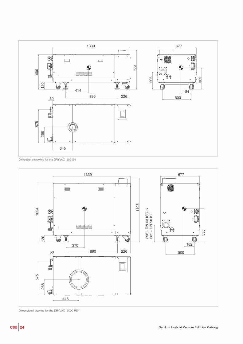
Dimensional drawing for the DRYVAC 650 S-i
500
120
226890
296
- D
N 6
3 IS
O-K
575
50
445
1339
268
1024 11
05
677
285
- D
N 5
0 K
F
535
182370
Dimensional drawing for the DRYVAC 5000 RS-i

C0525Oerlikon Leybold Vacuum Full Line Catalog
Pumping speed curves of the DRYVAC sprinter, resp. enduro 650 S, DRYVAC champion 650 S pumps and the DRYVAC champion 5000
Torr0.1 1 10 100 7500.001 0.010.0001
0
1000
2000
3000
cfm
Inlet pressure
0
1000
2000
3000
4000
5000
0.0001 0.001 0.01 0.1 1 10 100 1000
Pum
piin
g sp
eed
DRYVAC champion 5000 RS-i, WH2500@50 Hz/100 Hz
mbar
m3/h
100 Hz
50 Hz
0
100
200
300
400
500
600
700
0.001 0.01 0.1 1 10 100 1000
DRYVAC champion 650 S
mbarInlet pressure
m3/h
Pum
ping
spe
ed
Torr0.1 1 10 100 7500.001 0.01
0
100
200
300
400
cfm
0
100
200
300
400
500
600
700
0,001 0,01 0,1 1 10 100 1000
DRYVAC sprinter und enduro 650 S
mbarInlet pressure
m3/h
Pum
ping
spe
edTorr0.1 1 10 100 7500.001 0.01
0
100
200
300
400
cfm

C05 26 Oerlikon Leybold Vacuum Full Line Catalog
Technical Data DRYVAC enduro / sprinter / champion
5000 RS-i 650 S-i 650 S 650 S-rNominal pumping speed m3/h
(cfm)
Max. effective pumping speed m3/h
(cfm)
Ultimate pressure mbar
(Torr)
Permissible ambient temperature °C
(°F)
Water vapour tolerance
with > 20 hours l/min purge gas
or gas ballast mbar (Torr)
Water vapour capacity kg/h
Noise level at ultimate pressure
with silencer dB(A)
with permanent exhaust line dB(A)
Power consumption at ultimate pressure kW
Cooling
Electrical connection
Phases
Nominal power at 400 V kW
Nominal current at 400 V A
Intake connection DN
Exhaust side connection DN
Protection class EN 60529 IP
Weight kg
(lbs)
Dimensions (W x D x H) mm
(in.)
Cooling water connection
Threads, female G
Max. cooling water temperature °C
(°F)
Min. cooling water throughput, nominal
l/min
(US gallon/min)
Purge gas connection
(plugged connection)
5000 650 650 650
(2945) (383) (383) (383)
3800 650 650 650
(2238) (383) (383) (383)
5 x 10⁻⁴ 5 x 10⁻³ 5 x 10⁻³ 5 x 10⁻³
(4 x 10⁻⁴) (4 x 10⁻³) (4 x 10⁻³) (4 x 10⁻³)
+5 to +40 +5 to +40 +5 bis +50 +5 bis +50
(+41 to +104) (+41 to +104) (+41 to +122) (+41 to +122)
� 60 (� 45) � 60 (� 45) � 60 (� 45) � 60 (� 45)
25 25 25 25
67 65 67 67
67 65 65 65
� 9.5 � 7 � 7 � 7
water water water water
380-480 V, 50/60 Hz 380-480 V, 50/60 Hz 380-480 V, 50/60 Hz 380-480 V, 50/60 Hz
3-ph. 3-ph. 3-ph. 3-ph.
21 15 15 15
35 31 31 31
250 ISO-K 100 ISO-K 100 ISO-K 100 ISO-K
63 ISO-K or 50 KF 63 ISO-K 63 ISO-K 63 ISO-K
20 20 54 55
1200 750 580 540
(2646) (1654) (1279) (1191)
1340 x 670 x 1105 1340 x 670 x 680 1280 x 570 x 420 1200 x 450 x 400
(52.8 x 26.4 x 43.5) (52.8 x 26.4 x 26.8) (50.4 x 22.4 x 16.5) (47.2 x 17.7 x 15.7)
1/2 1/2 1/2 1/2
5 to 35 5 to 35 5 to 35 5 to 35
(41 to 95) (41 to 95) (41 to 95) (41 to 95)
11 7.5 7.5 7.5
(2.9) (2.0) (2.0) (2.0)
D10 D10 D10 D10

C0527Oerlikon Leybold Vacuum Full Line Catalog
Ordering Information
DRYVAC enduro / sprinter / championDRYVAC PLC/Touch Screen/ Frequency Purge gas Gas ballast Housing Lubricant Part No.
Software converter module module and feet
(ambient air)
enduro
650 S-r 1) no external (rack) none manual rubber feet synthetic oil 112065V01
650 S-r 1) no external (rack) single 24 V valve rubber feet synthetic oil 112065V05
650 S no on board none manual rubber feet synthetic oil 112065V10
650 S no on board single 24 V valve rubber feet synthetic oil 112065V15
sprinter
650 S no on board single none rubber feet PFPE 112065V20
650 S no on board none none base plate, castors,
adjustable feet PFPE 112065V25
650 S-i yes on board single none housing, castors,
adjustable feet PFPE 112065V40
champion
650 S no on board triple none rubber feet PFPE 112065V30
650 S-r, 200 V 1) no external (rack) triple none rubber feet PFPE 112065V35
650 S-i yes on board triple none housing, castors,
adjustable feet PFPE 112065V45
5000 RS-i yes on board triple none housing, castors,
adjustable feet PFPE 112500V45
5000 RS-i yes on board triple none housing, castors,
Exhaust connection adjustable feet PFPE
DN 50 ISO-KF 112500V60
Ordering Information
Accessories
Part No.
Profibus module for DRYVAC S/S-r 155212V
Relay module (digital output) for DRYVAC S/S-r 112005A01
Adapter DRYVAC for RUVAC 2001 112005A05
Adapter DRYVAC for RUVAC 4400/7000 112005A10
Non-return valve DRYVAC, DN 63 ISO-K 2) 112005A15
Silencer DN 63 ISO-K DRYVAC and SCREWLINE SP250 119002
2) Already integrated in all S-i/RS-i versions
C05 28 Oerlikon Leybold Vacuum Full Line Catalog
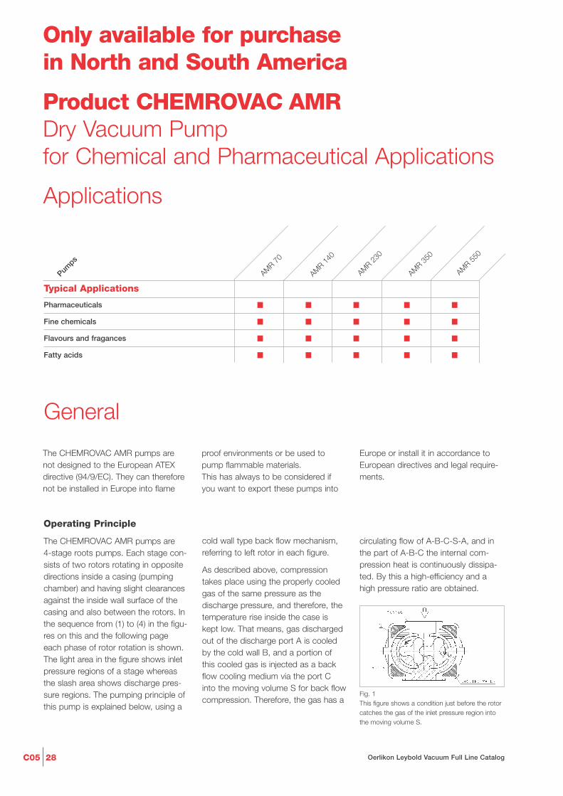
Product CHEMROVAC AMRDry Vacuum Pumpfor Chemical and Pharmaceutical Applications
Only available for purchase in North and South America
Applications
■ ■ ■ ■ ■
■ ■ ■ ■ ■
■ ■ ■ ■ ■
■ ■ ■ ■ ■
Pharmaceuticals
Fine chemicals
Flavours and fragances
Fatty acids
Pumps
AMR 70
AMR 140
AMR 230
Typical Applications
AMR 550
AMR 350
The CHEMROVAC AMR pumps arenot designed to the European ATEXdirective (94/9/EC). They can thereforenot be installed in Europe into flame
proof environments or be used topump flammable materials.This has always to be considered ifyou want to export these pumps into
Operating Principle
The CHEMROVAC AMR pumps are 4-stage roots pumps. Each stage con-sists of two rotors rotating in oppositedirections inside a casing (pumpingchamber) and having slight clearancesagainst the inside wall surface of thecasing and also between the rotors. Inthe sequence from (1) to (4) in the figu-res on this and the following pageeach phase of rotor rotation is shown.The light area in the figure shows inletpressure regions of a stage whereasthe slash area shows discharge pres-sure regions. The pumping principle ofthis pump is explained below, using a
circulating flow of A-B-C-S-A, and inthe part of A-B-C the internal com-pression heat is continuously dissipa-ted. By this a high-efficiency and ahigh pressure ratio are obtained.
cold wall type back flow mechanism,referring to left rotor in each figure.
As described above, compressiontakes place using the properly cooledgas of the same pressure as thedischarge pressure, and therefore, thetemperature rise inside the case iskept low. That means, gas dischargedout of the discharge port A is cooledby the cold wall B, and a portion ofthis cooled gas is injected as a backflow cooling medium via the port Cinto the moving volume S for back flowcompression. Therefore, the gas has a
Fig. 1This figure shows a condition just before the rotorcatches the gas of the inlet pressure region intothe moving volume S.
General
Europe or install it in accordance toEuropean directives and legal require-ments.

C0529Oerlikon Leybold Vacuum Full Line Catalog
Advantages to the User
- Oil free compression
- Reliable separation between sweptvolume and gear box side (avoidingof oil back streaming)
- Motor not on gear box side, no oilleaking by motor shaft
- Safe separation of motor and gearbox area by additional shaft sealpurge
- Materials of construction suitable formost chemicals to be pumped
- Flat speed curve from atmosphereto 10 mbar (7.5 Torr)
- Good liquid handling because ofvertical orientation
- Easy access of swept volume forcleaning
- Easy to equip with local certifiedflame proof motor
- Nearly no electrical control for stan-dard operation needed
Typical Applications
- Distillation
- Drying
- Freeze drying
- Degassing
- Central house vacuum
- Crystallisation
- Evaporation
Accessories
As standard accessory an exhaustsilencer is available for each pump.
The pumps can be combined withmechanical roots blowers to increasepumping speed and to achieve lowerultimate pressure.
CHEMROVAC AMR pumps can alsobe the basic part of a bespokensystem that complies to special pro-cess requirements to customer’sneeds.
Supplied Equipment
The basic pump CHEMROVAC AMR isa pump without a motor. A suitablemotor complying with the local regula-tions will normally be mounted byOerlikon Leybold Vacuum.In this case the CHEMROVAC AMR issupplied ready for installation andconnection.
In some cases the motor will be deli-vered and mounted by the end-user. Inthis case the user is responsible forcorrect selection and safe mounting ofthe motor. OLV will not take over anyresponsibility for the motor and motormounting in such a case.
The electrical connections to the pumpmust be provided by suitably trainedstaff of the customer.
The basic CHEMROVAC AMR pump isdelivered with:
- Nitrogen shaft seal purge unit
- The required amount of gear oil (issupplied separately)
- 2 crane eyes for transporting thepump
- Operating Instructions
Fig. 2In this figure, the rotor has completely caught thegas of the inlet pressure region into the movingvolume S. Gas which is already discharged out atexit port A is properly cooled by the cold outsidewall of the gas path B. One part of this gas flowsback through the port C into the moving volumeS. The other part of the cooled exhausted gas isflowing into the next stage of the pump.
Fig. 3As the rotor rotates further, the gas which hasbeen cooled properly by the cold wall B flows suf-ficiently into the S cavity; the pressure in thechamber S is approaching the discharge pressure.
Fig. 4In this condition the pressure in the moving volu-me portion S is approximately equal to the dis-charge pressure, and the discharge port A and thecavity S are just before opening to each other.
Moreover, because the casing enclo-sing the rotors is not cooled directly,the clearances between the rotor andthe casing is not reduced due to heatcontraction, reducing the possibility ofcontact between both.
In some cases condensable gas cancondense in the different stages accor-ding to its vapor pressure. Condensateeither condensed in the pump or asliquid carry over from the process will
flow down with the gas stream anddischarged to atmosphere in anexhaust drain tank.
The exhaust drain tank is mounted atthe exhaust of the last pump stage. Itis located either below the exhaustcooler (large pumps) or pump outletflange (small pumps). It collects liquidcondensed from the pump or theexhaust cooler.
The larger pumps are equipped with awater cooled exhaust cooler as stan-dard. The cooler is designed as shelland tube cooler. This reduces theexhaust gas temperature to an accep-table limit. Also vapors from theexhaust gas stream are partially con-densed. Condensed liquid is drainedinto the exhaust drain tank below thecondenser.

C05 30 Oerlikon Leybold Vacuum Full Line Catalog
CHEMROVAC AMR 70 to 550
CHEMROVAC AMR 70 (left) and AMR 550 (right)
0
50
100
150
200
250
300
350
400
450
500
0,1 1 10 100 1000
AMR 70
AMR 140
AMR 230
AMR 350
AMR 550
m3/h
Pressure
10-1 1 10 100 750Torr
300
200
100
1
50
cfm
Pum
ping
spe
ed
mbar
Pumping speed curves for the CHEMROVAC AMR at 50 Hz
Products
Pumping speed curves for the CHEMROVAC AMR at 60 Hz
0
100
200
300
400
500
600
0,1 1 10 100 1000
AMR 550
AMR 350
AMR 230
AMR 140
AMR 70
10-1 1 10 100 750Torr
300
200
100
1
50
cfm
m3/h
Pressure
Pum
ping
spe
ed
mbar

C0531Oerlikon Leybold Vacuum Full Line Catalog
Dimensional drawing of the CHEMROVAC AMR 70 and 140
Dimensional drawing of the CHEMROVAC AMR 230 to 550
Type A B 1 B 2 C D E F 1 F 2
AMR 230 mm 500 460 665 1295 910 555 235 265in. 19.69 18.11 26.18 50.98 35.83 21.85 9.25 10.43
AMR 350 mm 700 600 860 1565 1115 635 300 345in. 27.56 23.62 33.86 61.61 43.90 25.00 11.81 13.58
AMR 550 mm 700 600 860 1735 1115 740 300 345in. 27.56 23.62 33.86 68.31 43.90 29.13 11.81 13.58
Type A 1 A 2 B 1 B 2 C D E F 1 F 2
AMR 70 mm 500 570 420 570 1025 345 400 220 250in. 19.69 22.44 16.54 22.44 40.35 13.58 17.75 8.66 9.84
AMR 140 mm 500 570 460 665 1200 370 475 235 285in. 19.69 22.44 18.11 26.18 47.24 14.57 18.70 9.25 11.22

C05 32 Oerlikon Leybold Vacuum Full Line Catalog
Technical Data
Max. pumping speed (+/- 10%)
60 Hz m3 x h-1 (cfm)
50 Hz m3 x h-1 (cfm)
Ultimate total pressure, abs.
60 Hz mbar (Torr)
50 Hz mbar (Torr)
Max. permissible exhaust
back pressure, abs. mbar
(Torr)
Max. permissible inlet pressure, abs. mbar
(Torr)
Max. permissible inlet temperature °C (°F)
Permissible ambient temperature
for constant operation 1) °C
(°F)
Max. relative ambient moisture %
Max. permissible installation height m
(ft)
Sound pressure with silencer
at ultimate (± 3 dB(A))
60 Hz dB(A)
50 Hz dB(A)
Process flange size
inlet ANSI / lb ff
outlet ANSI / lb ff
Cooling water flange size
inlet Rc
outlet Rc
Shaft seal purge gas size Rc
Recommended shaft seal purge flow
gear side l/min (gallon/min)
motor side l/min (gallon/min)
Type of gas
Dew point of supply gas °C (°F)
Maximum particle size in gas µm
Weight without motor kg (lbs)
Assumed weight with motor kg (lbs)
1) If you operate the pump in an ambient temperature between -20 and +5 °C (-4 to +41 °F) we recommend that you leave the pump constantly operating and only shut down the pump for maintenance purposes. The pump must be pre-warmed if you want to start it in an ambient temperature range between -20 and +5 °C (-4 to +41 °F).
75 (44) 138 (81) 228 (134) 354 (208) 546 (321)
60 (36) 120 (71) 192 (113) 288 (170) 438 (258)
1.0 (0.75) 0.7 (0.53) 0.5 (0.38) 0.7 (0.53) 0.5 (0.38)
1.8 (1.35) 0.9 (0.68) 0.7 (0.53) 0.9 (0.68) 0.8 (0.60)
900 to 1200 900 to 1200 900 to 1200 900 to 1200 900 to 1200
(575 to 900) (575 to 900) (575 to 900) (575 to 900) (575 to 900)
1050 1050 1050 1050 1050
(788) (788) (788) (788) (788)
50 (122) 50 (122) 50 (122) 50 (122) 50 (122)
-20 to +40 -20 to +40 -20 to +40 -20 to +40 -20 to +40
(-4 to +104) (-4 to +104) (-4 to +104) (-4 to +104) (-4 to +104)
up to 90 up to 90 up to 90 up to 90 up to 90
up to 1000 up to 1000 up to 1000 up to 1000 up to 1000
(up to 3280) (up to 3280) (up to 3280) (up to 3280) (up to 3280)
76 79 81 81 82
73 75 77 78 79
1 1/2" / 125 2" / 125 2 1/2" / 125 3" / 125 4" / 125
1 1/2" / 125 1 1/2" / 125 2 1/2" / 125 2 1/2" / 125 2 1/2" / 125
1/2" 1/2" 1/2" 1/2" 1/2"
1/2" 1/2" 1/2" 1/2" 1/2"
3/8" 3/8" 3/8" 3/8" 3/8"
3.0 (0.8) 5.0 (1.3) 5.0 (1.3) 6.0 (1.6) 6.0 (1.6)
0,5 (0.15) 1.0 (0.3) 1.0 (0.3) 2.0 (0.6) 2.0 (0.6)
nitrogen nitrogen nitrogen nitrogen nitrogen
-15 (+5) -15 (+5) -15 (+5) -15 (+5) -15 (+5)
3 3 3 3 3
180 (397) 235 (520) 280 (617) 535 (1180) 590 (1300)
235 (520) 319 (705) 396 (875) 708 (1560) 816 (1800)
CHEMROVAC
AMR 70 AMR 140 AMR 230 AMR 350 AMR 550

C0533Oerlikon Leybold Vacuum Full Line Catalog
Additional Technical Data
Motor flame proof protection
Start-up method
Voltage V
Installed power60 Hz kW (HP)50 Hz kW (HP)
Absorbed power at ultimate pressure60 Hz kW (HP)50 Hz kW (HP)
Motor frame size NEMAIEC
No. of phases
No. of poles
Motor frequency Hz
Operating frequency Hz
Nominal revolution 1/min
Cooling
Minimum cooling water consumption(at 25 °C (77 °F) inlet temperature)
60 Hz l/min (gallon/min)50 Hz l/min (gallon/min)
Cooling water temperature °C (°F)°C (°F)
Cooling water supply pressure, abs. bar(psi)
Lubrication bearingmotor side (grease) mlgear side (oil)
Oil type for gear box
Volume gear box oil l (gallon)
to local standards, e.g. class 1, division 1, C&D, or Ex d IIB
direct on line or via frequency converter
depending on local requirements
3.7 (5.0) 5.5 (7.5) 7.5 (10.0) 15.0 (20.0) 18.5 (25.0)3.7 (5.0) 5.5 (7.5) 7.5 (10.0) 15.0 (20.0) 18.5 (25.0)
2.1 (2.8) 3.3 (4.4) 4.8 (6.4) 9.0 (12.1) 12.5 (16.8)1.8 (2.4) 3.0 (4.0) 4.1 (5.5) 7.0 (9.4) 10.0 (13.4)
184TC 213TC 215TC 256TC 284TSC112 M 132 S 132 S 160 M 160 L
3 3 3 3 3
2 2 2 2 2
50 or 60, depending on local conditions
26 to 60
3000 or 3600, depending on motor frequency
water, direct without temperature control valve
5.0 (1.3) 7.0 (1.9) 10.0 (2.7) 20.0 (5.3) 28.0 (7.4)5.0 (1.3) 7.0 (1.9) 10.0 (2.7) 20.0 (5.3) 28.0 (7.4)
+10 to +35 +10 to +35 +10 to +35 +10 to +35 +10 to +35(+50 to +95) (+50 to +95) (+50 to +95) (+50 to +95) (+50 to +95)
3 to 7 3 to 7 3 to 7 3 to 7 3 to 7(44 to 102) (44 to 102) (44 to 102) (44 to 102) (44 to 102)
100 200 200 260 260depends on oil capacity
LVO 130 LVO 130 LVO 130 LVO 130 LVO 130
1.0 (0.3) 1.0 (0.3) 1.0 (0.3) 4.0 (1.1) 4.0 (1.1)
CHEMROVAC
AMR 70 AMR 140 AMR 230 AMR 350 AMR 550
Ordering Information
Dry vacuum pump
for chemical and pharmaceutical application
CHEMROVAC AMR (without motor)
CHEMROVAC AMR
(with NEMA motor Class 1,
Div. 1, Group C & D, 230/460 V, 60 Hz)
Accessories
Exhaust silencer, filled with mineral wool
Part No. Part No. Part No. Part No. Part No.
134 101 134 102 134 103 134 104 134 105
134 201 V 134 202 V 134 203 V 134 204 V 134 205 V
134 121 134 121 134 122 134 122 134 122
CHEMROVAC
AMR 70 AMR 140 AMR 230 AMR 350 AMR 550

OerlikonLeybold Vacuum GmbHBonner Strasse 498D-50968 ColognePhone: +49-(0)221-347 0Fax: +49-(0)221-347 [email protected]
P.R. ChinaOerlikon Leybold Vacuum (Tianjin)International Trade Co. Ltd.Beichen EconomicDevelopment Area (BEDA),No.8 Western Shuangchen RoadTianjin 300400ChinaSales and Service:Phone: +86-22-2697 0808Fax: +86-22-2697 4061Fax: +86-22-2697 [email protected]@[email protected]
Oerlikon Leybold Vacuum (Tianjin) Co. Ltd.Beichen EconomicDevelopment Area (BEDA),No.8 Western Shuangchen RoadTianjin 300400ChinaSales and Service:Phone: +86-22-2697 0808Fax: +86-22-2697 [email protected]@[email protected]
Oerlikon Leybold Vacuum (Tianjin)International Trade Co. Ltd.Shanghai Branch:No.3376 Fu Te Dong San RoadWaigaoqiao Free Trade ZoneShanghai 200131ChinaSales and Service:Phone: +86-21-5064-4666Fax: [email protected]@[email protected]
Oerlikon Leybold Vacuum (Tianjin)International Trade Co. Ltd.Guangzhou Office and Service Center1st F, Main BuildingScience City Plaza,No.111 Science Revenue,Guangzhou Science City (GZSC) 510663, Guangzhou,ChinaSales:Phone: +86-20-223 23 980Fax:+86-20-223 23 [email protected]@[email protected]
Oerlikon Leybold Vacuum (Tianjin)International Trade Co. Ltd.Beijing Branch:1-908, Beijing Landmark Towers8 North Dongsanhuan RoadBeijing 100004ChinaSales:Phone: +86-10-6590-7622Fax: [email protected]@oerlikon.com
IndiaOerlikon Leybold Vacuum India Pvt Ltd.EL 22, J-BlockMIDC BhosariPune 411026IndiaSales and Service:Phone: +91-20-3061 6000Fax: +91-20-2712 [email protected]@oerlikon.com
NetherlandsOerlikon Leybold Vacuum Nederland B.V.Proostwetering 24NNL-3543 AE UtrechtSales and Service: Phone: +31-(30) 242 6330Fax: +31-(30) 242 [email protected]@oerlikon.com
SpainOerlikon Leybold Vacuum Spain, S.A.C/ Huelva 7E-08940 Cornellà de Llobregat(Barcelona)Sales:Phone: +34-93-666 43 11Fax: +34-93-666 43 [email protected]:Phone: +34-93-666 46 16Fax: +34-93-685 43 [email protected]
SwitzerlandOerlikon Leybold Vacuum Schweiz AGLeutschenbachstrasse 55CH-8050 ZürichSales:Phone: +41-44-308 40 50Fax: +41-44-302 43 [email protected]: Phone: +41-44-308 40 62Fax: +41-44-308 40 [email protected]
Oerlikon Leybold Vacuum USA Inc.5700 Mellon RoadUSA-Export, PA 15632Phone: +1-724-327-5700Fax: [email protected]:Eastern & Central time zonesPhone: +1-724-327-5700Fax: +1-724-333-1217Pacific, Mountain, Alaskan &Hawaiian time zonesPhone: +1-408-436-2828Fax: +1-408-436-2849Service:Phone: +1-724-327-5700Fax: +1-724-325-3577
BelgiumOerlikon Leybold Vacuum Nederland B.V.Belgisch bijkantoorLeuvensesteenweg 542-9AB-1930 ZaventemSales:Phone: +32-2-711 00 83Fax: +32-2-720 83 [email protected]:Phone: +32-2-711 00 82Fax: +32-2-720 83 [email protected]
FranceOerlikon Leybold Vacuum France S.A.7, Avenue du QuébecZ.A. de Courtaboeuf 1 - B.P. 42F-91942 Courtaboeuf CedexSales and Service:Phone: +33-1-69 82 48 00 Fax: +33-1-69 07 57 38 [email protected]@oerlikon.com
Oerlikon Leybold Vacuum France S.A.Valence Factory640, Rue A. BergèsB.P. 107 640F-26501 Bourg-lès-Valence CedexService:Phone: +33-4-75 82 33 00Fax: +33-4-75 82 92 [email protected]
Great BritainOerlikon Leybold Vacuum UK LTD.Silverglade Business ParkLeatherhead Road Unit 2KT9 2QL Chessington, Surrey(London)Sales:Phone: +44-13-7273 7300Fax: +44-13-7273 [email protected]:Phone: +44-20-8971 7030Fax: +44-20-8971 [email protected]
ItalyOerlikon Leybold Vacuum Italia S.r.l.Via Trasimeno 8I-20128 MilanoSales:Phone: +39-02-27 22 31Fax: +39-02-27 20 96 [email protected]:Phone: +39-02-27 22 31Fax: +39-02-27 22 32 [email protected]
Oerlikon Leybold Vacuum GmbHBonner Strasse 498D-50968 ColognePhone: +49-(0)221-347 1234Fax: +49-(0)221-347 [email protected]
Oerlikon Leybold Vacuum GmbHSales Area North/NortheastBranch Office BerlinIndustriestrasse 10bD-12099 BerlinPhone: +49-(0)30-435 609 0Fax: +49-(0)30-435 609 [email protected]
Oerlikon Leybold Vacuum GmbHSales Area South/SouthwestBranch Office MunichKarl-Hammerschmidt-Strasse 34D-85609 Aschheim-DornachPhone: +49-(0)89-357 33 9-10Fax: +49-(0)89-357 33 [email protected]@oerlikon.com
Oerlikon Leybold Vacuum GmbHSales Area West & BeneluxBranch Office CologneBonner Strasse 498D-50968 ColognePhone: +49-(0)221-347 1270Fax: +49-(0)221-347 [email protected]
Oerlikon Leybold Vacuum GmbHService Competence CenterEmil-Hoffmann-Strasse 43D-50996 Cologne-SuerthPhone: +49-(0)221-347 1538Fax: +49-(0)221-347 [email protected]
OerlikonLeybold Vacuum GmbHMobil Customer ServiceEmil-Hoffmann-Strasse 43D-50996 Cologne-SuerthPhone: +49-(0)221-347 2001Fax: +49-(0)221-347 [email protected]
Oerlikon Leybold VacuumDresden GmbHService Competence CenterZur Wetterwarte 50, Haus 304D-01109 DresdenService:Phone: +49-(0)351-88 55 00Fax: +49-(0)351-88 55 [email protected]
JapanOerlikon Leybold VacuumJapan Co., Ltd.Headquarter23-3, Shin-Yokohama3-chomeTobu A.K. Bldg. 4th FloorKohoku-kuYokohama-shi 222-0033Sales:Phone: +81-45-471-3330Fax: [email protected]@oerlikon.com
Oerlikon Leybold VacuumJapan Co., Ltd.Osaka Sales Office3F, Shin-Osaka Terasaki No.3 Bldg.1-5-28 Nishi-MiyaharaYodogawa-ku, Osaka-shiOsaka 532-0004Phone: +81-6-6399-6271Fax: [email protected]@oerlikon.com
Oerlikon Leybold VacuumJapan Co., Ltd.Tsukuba Technical Service CenterKogyo Danchi21, Kasuminosato,Ami-machi, Inashiki-gunIbaraki-ken, 300-0315Service:Phone: +81-298 89 2841Fax: +81-298 89 [email protected]@oerlikon.com
South KoreaOerlikon Leybold Vacuum Korea Ltd.3F. Jellzone 2 TowerJeongja-dong 159-4Bundang-gu Sungnam-siGyeonggi-doBundang 463-384, KoreaSales:Phone: +82-31 785 1367Fax: +82-31 785 [email protected]
Service:623-7, Upsung-DongCheonan-SiChungcheongnam-DoKorea 330-290Phone: +82-41 589 3035Fax: +82-41 588 [email protected]
SingaporeOerlikon Leybold VacuumSingapore Pte Ltd.1 Science Park RoadSingapore Science Park 2#02-12, Capricorn BuildingSingapore 117528Sales and Service:Phone: +65-6303 7030Fax: +65-6773 [email protected]@oerlikon.com
TaiwanOerlikon Leybold Vacuum Taiwan Ltd.No 416-1, Sec. 3Chunghsin Road., ChutungHsinchu County 310Taiwan, R.O.C.Sales and Service:Phone: +886-3-500 1688Fax: +886-3-583 [email protected]@oerlikon.com
Germany Europe Asia
Sales and Service
America
LV_1
0133
_201
1
01
.11
OerlikonLeybold Vacuum USA Inc.5700 Mellon RoadUSA-Export, PA 15632Phone: +1-724-327-5700Fax: [email protected]