Screw shaft outer diameter - THK Global Top | THK Global Top · A To download a desired data,...
27
A15-182 To download a desired data, search for the corresponding model number in the Technical site. https://tech.thk.com Preload Type of Precision Ball Screw Screw shaft outer diameter 14 to 18 Lead 4 to 16 (Greasing hole) DIK (1404 to 2510) 60° A PCD Tw φ d2 B2 B1 φ D1 φ dp φ d1 φ dc h H φ Dg6 φ d L1 (Greasing hole) 4- φ d1 PCD Tw A 30° 30° B1 B2 B3 N1 L1 H φ D1 φ D2 φ Dg6 φ dc φ d φ dp BLW Screw shaft outer diameter Lead Model No. Ball center- to-center diameter Thread minor diameter No. of loaded circuits Basic load rating Rigidity Ca C 0a K Outer diameter Flange diameter d Ph dp dc Rows × turns kN kN N/m D D 1 D 2 14 4 DIK 1404-4 14.5 11.8 2×1 3 5.1 190 26 45 — DIK 1404-6 14.5 11.8 3×1 4.2 7.7 280 26 45 — 15 10 BLW 1510-5.6 15.75 12.5 2×2.8 14.3 27.8 680 43 64 34 16 4 BNFN 1604-3 16.5 13.8 2×1.5 5.1 10.5 350 36 59 — 5 BIF 1605-5 16.75 13.2 1×2.5 7.4 13.9 330 40 60 — DIK 1605-6 16.75 13.2 3×1 7.4 13 310 30 49 — BNFN 1605-2.5 16.75 13.2 1×2.5 7.4 13.9 330 40 60 — BNFN 1605-3 16.75 13.2 2×1.5 8.7 16.8 390 40 60 — BNFN 1605-5 16.75 13.2 2×2.5 13.5 27.8 640 40 60 — 6 BIF 1606-5 16.8 13.2 1×2.5 7.5 14 330 40 60 — 10 BNFN 1610-1.5 16.8 13.2 1×1.5 4.8 8.5 210 40 63 — 16 BLW 1616-3.6 16.65 13.7 2×1.8 7.1 14.3 440 41 60 32 18 10 BIF 1810-3 18.8 15.5 1×1.5 5.1 9.6 230 42 65 — BNFN 1810-2.5 18.8 15.5 1×2.5 7.8 15.9 360 42 65 — BNFN 1810-3 18.8 15.5 2×1.5 9.2 19.1 430 42 65 — Note) The model numbers in dimmed type indicate semi-standard types. If desiring them, contact THK. Model BLW cannot be attached with seal.
Transcript of Screw shaft outer diameter - THK Global Top | THK Global Top · A To download a desired data,...

A15-182 To download a desired data, search for the corresponding model number in the Technical site. https://tech.thk.com
Preload Type of PrecisionBall Screw
Screw shaft outer diameter 14 to 18
Lead 4 to 16
(Greasing hole)
DIK (1404 to 2510)60°
A
PCD
Tw
φ d2
B2
B1
φ D1 φ dp
φ d1
φ dc
hH
φ Dg6φ d
L1
(Greasing hole)
4-φ d1
PCD
Tw A
30°30° B1
B2 B3
N1
L1
H
φ D1φ D2φ Dg6 φ dc φ dφ dp
BLW
Screw shaft outer
diameter
Lead
Model No.
Ball center-
to-center diameter
Thread minor
diameter
No. of loaded circuits
Basic load rating Rigidity
Ca C 0 a K Outerdiameter
Flangediameter
d Ph dp dc Rows × turns kN kN N/m D D 1 D 2
14 4 DIK 1404-4 14.5 11.8 2×1 3 5.1 190 26 45 — DIK 1404-6 14.5 11.8 3×1 4.2 7.7 280 26 45 —
15 10 BLW 1510-5.6 15.75 12.5 2×2.8 14.3 27.8 680 43 64 34
16
4 BNFN 1604-3 16.5 13.8 2×1.5 5.1 10.5 350 36 59 —
5
BIF 1605-5 16.75 13.2 1×2.5 7.4 13.9 330 40 60 — DIK 1605-6 16.75 13.2 3×1 7.4 13 310 30 49 — BNFN 1605-2.5 16.75 13.2 1×2.5 7.4 13.9 330 40 60 — BNFN 1605-3 16.75 13.2 2×1.5 8.7 16.8 390 40 60 — BNFN 1605-5 16.75 13.2 2×2.5 13.5 27.8 640 40 60 —
6 BIF 1606-5 16.8 13.2 1×2.5 7.5 14 330 40 60 — 10 BNFN 1610-1.5 16.8 13.2 1×1.5 4.8 8.5 210 40 63 — 16 BLW 1616-3.6 16.65 13.7 2×1.8 7.1 14.3 440 41 60 32
18 10 BIF 1810-3 18.8 15.5 1×1.5 5.1 9.6 230 42 65 — BNFN 1810-2.5 18.8 15.5 1×2.5 7.8 15.9 360 42 65 — BNFN 1810-3 18.8 15.5 2×1.5 9.2 19.1 430 42 65 —
Note) The model numbers in dimmed type indicate semi-standard types. If desiring them, contact THK. Model BLW cannot be attached with seal.

A15-183
Ball Screw
Precision Ball Screw
(Greasing hole)
BIF
PCD
A
60°
φ d2
B1
φ D1 φ dp
φ d1
φ dc
h H
φ Dg6φ d
L1
(Greasing hole)
PCD
A60°
φ d2
B1
B2
φ D1 φ dp
φ d1
φ dc
h H
φ Dg6φ d
L1
BNFN
Unit: mm
Nut dimensions Screw shaft inertial
moment/mm Nut
mass Shaftmass Overall
length Greasinghole
L 1 H B 1 B 2 B 3 PCD d 1 d 2 h Tw N 1 A kg•cm 2 /mm kg kg/m 48 10 38 10 — 35 4.5 8 4.5 29 — M6 2.96×10 -4 0.2 1.0 60 10 50 10 — 35 4.5 8 4.5 29 — M6 2.96×10 -4 0.23 1.0 89 10 69 18.7 28.6 52 5.5 — — 46 5 M6 3.9×10 -4 0.81 1.07 85 11 74 — — 47 5.5 9.5 5.5 — — M6 5.05×10 -4 0.67 1.35 56 10 46 — — 50 4.5 8 4.5 — — M6 5.05×10 -4 0.56 1.25 60 10 50 10 — 39 4.5 8 4.5 31 — M6 5.05×10 -4 0.3 1.25 76 10 66 55 — 50 4.5 8 4.5 — — M6 5.05×10 -4 0.66 1.25 96 10 86 75 — 50 4.5 8 4.5 — — M6 5.05×10 -4 0.81 1.25
106 10 96 85 — 50 4.5 8 4.5 — — M6 5.05×10 -4 0.88 1.25 62 10 52 — — 50 4.5 8 4.5 — — M6 5.05×10 -4 0.56 1.25 72 11 61 — — 51 5.5 9.5 5.5 — — M6 5.05×10 -4 0.67 1.41
84.5 10 65.5 18.1 27.1 49 4.5 — — 44 6 M6 5.05×10 -4 0.67 1.42 75 12 63 — — 53 5.5 9.5 5.5 — — M6 8.09×10 -4 0.75 1.81 119 12 107 94 — 53 5.5 9.5 5.5 — — M6 8.09×10 -4 1.09 1.81 135 12 123 110 — 53 5.5 9.5 5.5 — — M6 8.09×10 -4 1.21 1.81
For model number coding, see A15-248 .
Options⇒A15-349

A15-184 To download a desired data, search for the corresponding model number in the Technical site. https://tech.thk.com
Preload Type of PrecisionBall Screw
Screw shaft outer diameter 20
Lead 4 to 5
(Greasing hole)
DIK (1404 to 2510)60°
A
PCD
Tw
φ d2
B2
B1
φ D1 φ dp
φ d1
φ dc
h H
φ Dg6φ d
L1
(Greasing hole)
BIF
PCD
A
60°
φ d2
B1
φ D1 φ dp
φ d1
φ dc
h H
φ Dg6φ d
L1
Screw shaft outer
diameter
Lead
Model No.
Ball center-
to-center diameter
Thread minor
diameter
No. of loadedcircuits
Basic load rating Rigidity
Ca C 0 a K
d Ph dp dc Rows × turns kN kN N/m
20
4
BIF 2004-5 20.5 17.8 1×2.5 4.8 10.9 360 DIK 2004-6 20.5 17.8 3×1 5.2 11.6 380 DIK 2004-8 20.5 17.8 4×1 6.6 15.5 510 BNFN 2004-2.5 20.5 17.8 1×2.5 4.8 10.9 360 BNFN 2004-5 20.5 17.8 2×2.5 8.6 21.8 700
5
BIF 2005-5 20.75 17.2 1×2.5 8.3 17.4 390 DIK 2005-6 20.75 17.2 3×1 8.5 17.3 310 BNFN 2005-2.5 20.75 17.2 1×2.5 8.3 17.4 390 BNFN 2005-3 20.75 17.2 2×1.5 9.7 21 470 BNFN 2005-3.5 20.75 17.2 1×3.5 11.1 24.5 550 BNFN 2005-5 20.75 17.2 2×2.5 15.1 35 760
Note) The model numbers in dimmed type indicate semi-standard types. If desiring them, contact THK.

A15-185
Ball Screw
Precision Ball Screw
(Greasing hole)
PCD
A60°
φ d2
B1
B2
φ D1 φ dp
φ d1
φ dc
h H
φ Dg6φ d
L1
BNFN
Unit: mm
Nut dimensions Screw shaft inertia
moment/mm
Nutmass
Shaftmass Outer
diameter Flange
diameter Overalllength Greasing
hole
D D 1 L 1 H B 1 B 2 PCD d 1 ×d 2 ×h Tw A kg•cm 2 /mm kg kg/m 40 63 53 11 42 — 51 5.5×9.5×5.5 — M6 1.23×10 -3 0.49 2.18 32 56 62 11 51 15 44 5.5×9.5×5.5 35 M6 1.23×10 -3 0.34 2.18 32 56 70 11 59 15 44 5.5×9.5×5.5 35 M6 1.23×10 -3 0.37 2.18 40 63 69 11 58 — 51 5.5×9.5×5.5 — M6 1.23×10 -3 0.58 2.18 40 63 93 11 82 — 51 5.5×9.5×5.5 — M6 1.23×10 -3 0.74 2.18 44 67 56 11 45 — 55 5.5×9.5×5.5 — M6 1.23×10 -3 0.57 2.06 34 58 61 11 50 10 46 5.5×9.5×5.5 36 M6 1.23×10 -3 0.38 2.06 44 67 76 11 65 53 55 5.5×9.5×5.5 — M6 1.23×10 -3 0.77 2.06 44 67 97 11 86 74 55 5.5×9.5×5.5 — M6 1.23×10 -3 0.93 2.06 44 67 85 11 74 62 55 5.5×9.5×5.5 — M6 1.23×10 -3 0.86 2.06 44 67 106 11 95 83 55 5.5×9.5×5.5 — M6 1.23×10 -3 0.98 2.06
For model number coding, see A15-248 .
Options⇒A15-349

A15-186 To download a desired data, search for the corresponding model number in the Technical site. https://tech.thk.com
Preload Type of PrecisionBall Screw
Screw shaft outer diameter 20
Lead 6 to 20
(Greasing hole)
DIK (1404 to 2510)60°
A
PCD
Tw
φ d2
B2
B1
φ D1 φ dp
φ d1
φ dc
h H
φ Dg6φ d
L1
(Greasing hole)
4-φ d1
PCD
Tw A
30°30° B1
B2 B3
N1
L1
H
φ D1φ D2φ Dg6 φ dc φ dφ dp
BLW
Screw shaft outer
diameter
Lead
Model No.
Ball center-
to-center diameter
Thread minor
diameter
No. of loaded circuits
Basic load rating Rigidity
Ca C 0 a K Outerdiameter
Flangediameter
d Ph dp dc Rows × turns kN kN N/m D D 1 D 2
20
6
BIF 2006-3 20.75 17.2 1×1.5 5.4 10.5 250 48 71 — BIF 2006-5 20.75 17.2 1×2.5 8.3 17.5 390 48 71 — DIK 2006-6 21 16.4 3×1 11.4 21.5 410 35 58 — BNFN 2006-2.5 20.75 17.2 1×2.5 8.3 17.5 390 48 71 — BNFN 2006-3 20.75 17.2 2×1.5 9.7 21 470 48 71 — BNFN 2006-3.5 20.75 17.2 1×3.5 11.1 24.5 550 48 71 — BNFN 2006-5 20.75 17.2 2×2.5 15.1 35 760 48 71 —
8 DIK 2008-4 21 16.4 2×1 8.1 14.4 280 35 58 — BNFN 2008-2.5 21 16.4 1×2.5 15.1 35 760 46 74 —
10 BNFN 2010A-1.5 21 16.4 1×1.5 7.2 13.2 250 46 74 — 12 BNFN 2012-1.5 21 16.4 1×1.5 7.1 12.5 250 48 71 — 20 BLW 2020-3.6 20.75 17.5 2×1.8 11.1 24.7 570 48 69 39
Note) The model numbers in dimmed type indicate semi-standard types. If desiring them, contact THK. Model BLW cannot be attached with seal.

A15-187
Ball Screw
Precision Ball Screw
Options⇒A15-349
(Greasing hole)
BIF
PCD
A
60°
φ d2
B1
φ D1 φ dp
φ d1
φ dc
h H
φ Dg6φ d
L1
(Greasing hole)
PCD
A60°
φ d2
B1
B2
φ D1 φ dp
φ d1
φ dc
h H
φ Dg6φ d
L1
BNFN
Unit: mm
Nut dimensions Screw shaft inertial
moment/mm
Nutmass
Shaftmass Overall
length Greasinghole
L 1 H B 1 B 2 B 3 PCD d 1 d 2 h Tw N 1 A kg•cm 2 /mm kg kg/m 56 11 45 — — 59 5.5 9.5 5.5 — — M6 1.23×10 -3 0.74 2.13 62 11 51 — — 59 5.5 9.5 5.5 — — M6 1.23×10 -3 0.8 2.13 76 11 65 15 — 46 5.5 9.5 5.5 36 — M6 1.23×10 -3 0.48 1.93 86 11 75 — — 59 5.5 9.5 5.5 — — M6 1.23×10 -3 1.05 2.13 110 11 99 — — 59 5.5 9.5 5.5 — — M6 1.23×10 -3 1.3 2.13 98 11 87 — — 59 5.5 9.5 5.5 — — M6 1.23×10 -3 1.17 2.13 122 11 111 — — 59 5.5 9.5 5.5 — — M6 1.23×10 -3 1.42 2.13 69 11 58 15 — 46 5.5 9.5 5.5 36 — M6 1.23×10 -3 0.45 2.06
100 15 85 — — 59 5.5 9.5 5.5 — — M6 1.23×10 -3 1.08 2.06 98 15 83 67 — 59 5.5 9.5 5.5 — — M6 1.23×10 -3 1.06 2.14
100 18 82 — — 59 5.5 9.5 5.5 — — M6 1.23×10 -3 1.3 2.19 105 10 84 25 36 57 5.5 — — 50 5 M6 1.23×10 -3 0.54 2.25
For model number coding, see A15-248 .

A15-188 To download a desired data, search for the corresponding model number in the Technical site. https://tech.thk.com
Preload Type of PrecisionBall Screw
Screw shaft outer diameter 25
Lead 4 to 6
(Greasing hole)
DIK (1404 to 2510)60°
A
PCD
Tw
φ d2
B2
B1
φ D1 φ dp
φ d1
φ dc
h H
φ Dg6φ d
L1
(Greasing hole)
BIF
PCD
A
60°
φ d2
B1
φ D1 φ dp
φ d1
φ dc
hH
φ Dg6φ d
L1
Screw shaft outer
diameter
Lead
Model No.
Ball center-
to-centerdiameter
Thread minor
diameter
No. of loadedcircuits
Basic load rating Rigidity
Ca C 0 a K
d Ph dp dc Rows × turns kN kN N/m
25
4
DIK 2504-6 25.5 22.8 3×1 5.7 15 470 DIK 2504-8 25.5 22.8 4×1 7.4 19.9 620 ○ BNFN 2504-2.5 25.5 22.8 1×2.5 5.2 13.7 420 ○ BNFN 2504-5 25.5 22.8 2×2.5 9.5 27.3 820
5
DIK 2505-6 25.75 22.2 3×1 9.7 22.6 490 ○ BIF 2505-3 25.75 22.2 1×1.5 6 13.1 280 ○ BIF 2505-5 25.75 22.2 1×2.5 9.2 22 470 ○ BNFN 2505-2.5 25.75 22.2 1×2.5 9.2 22 470 ○ BNFN 2505-3 25.75 22.2 2×1.5 10.8 26.4 560 ○ BNFN 2505-3.5 25.75 22.2 1×3.5 12.3 30.7 650 ○ BNFN 2505-5 25.75 22.2 2×2.5 16.7 44 910
6 DIK 2506-4 26 21.4 2×1 9.1 18 330 DIK 2506-6 26 21.4 3×1 12.8 27 490
Note) The model numbers in dimmed type indicate semi-standard types. If desiring them, contact THK. Those models marked with ○ can be attached with QZ Lubricator or the wiper ring. For dimensions of the ball screw nut with either accessory being attached, see A15-356 .
A15-189
Ball Screw
Precision Ball Screw
Options⇒A15-349
(Greasing hole)
PCD
A60°
φ d2
B1
B2
φ D1 φ dp
φ d1
φ dc
h H
φ Dg6φ d
L1
BNFN
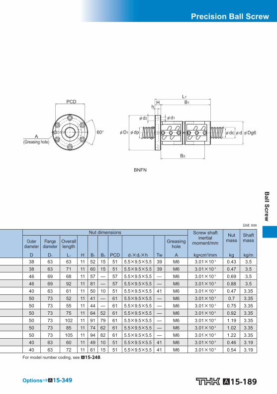
Unit: mm
Nut dimensions Screw shaft inertial
moment/mm
Nutmass
Shaftmass Outer
diameter Flange
diameter Overalllength Greasing
hole
D D 1 L 1 H B 1 B 2 PCD d 1 ×d 2 ×h Tw A kg•cm 2 /mm kg kg/m 38 63 63 11 52 15 51 5.5×9.5×5.5 39 M6 3.01×10 -3 0.43 3.5 38 63 71 11 60 15 51 5.5×9.5×5.5 39 M6 3.01×10 -3 0.47 3.5 46 69 68 11 57 — 57 5.5×9.5×5.5 — M6 3.01×10 -3 0.69 3.5 46 69 92 11 81 — 57 5.5×9.5×5.5 — M6 3.01×10 -3 0.88 3.5 40 63 61 11 50 10 51 5.5×9.5×5.5 41 M6 3.01×10 -3 0.47 3.35 50 73 52 11 41 — 61 5.5×9.5×5.5 — M6 3.01×10 -3 0.7 3.35 50 73 55 11 44 — 61 5.5×9.5×5.5 — M6 3.01×10 -3 0.75 3.35 50 73 75 11 64 52 61 5.5×9.5×5.5 — M6 3.01×10 -3 0.92 3.35 50 73 102 11 91 79 61 5.5×9.5×5.5 — M6 3.01×10 -3 1.19 3.35 50 73 85 11 74 62 61 5.5×9.5×5.5 — M6 3.01×10 -3 1.02 3.35 50 73 105 11 94 82 61 5.5×9.5×5.5 — M6 3.01×10 -3 1.22 3.35 40 63 60 11 49 10 51 5.5×9.5×5.5 41 M6 3.01×10 -3 0.46 3.19 40 63 72 11 61 15 51 5.5×9.5×5.5 41 M6 3.01×10 -3 0.54 3.19
For model number coding, see A15-248 .

A15-190 To download a desired data, search for the corresponding model number in the Technical site. https://tech.thk.com
Preload Type of PrecisionBall Screw
Screw shaft outer diameter 25
Lead 6 to 25
(Greasing hole)
DIK (1404 to 2510)60°
A
PCD
Tw
φ d2
B2
B1
φ D1 φ dp
φ d1
φ dc
h H
φ Dg6φ d
L1
(Greasing hole)
4-φ d1
PCD
Tw A
30°30° B1
B2 B3
N1
L1
H
φ D1φ D2φ Dg6 φ dc φ dφ dp
BLW
Screw shaftouter
diameter
Lead
Model No.
Ball center-
to-center diameter
Thread minor
diameter
No. of loadedcircuits
Basic load rating Rigidity
Ca C 0 a K Outerdiameter
Flangediameter
d Ph dp dc Rows × turns kN kN N/m D D 1 D 2
25
6
○ BNFN 2506-2.5 26 21.4 1×2.5 12.5 27.3 490 53 76 — ○ BNFN 2506-3 26 21.4 2×1.5 14.6 32.8 580 53 76 — ○ BNFN 2506-3.5 26 21.4 1×3.5 15.1 35.9 670 53 76 — ○ BNFN 2506-5 26 21.4 2×2.5 22.5 54.8 940 53 76 —
8
DIK 2508-4 26 21.4 2×1 9.2 18.8 340 40 63 — DIK 2508-6 26 21.4 3×1 13.1 28.1 500 40 63 — ○ BIF 2508-5 26.25 20.5 1×2.5 15.8 32.8 500 58 85 — ○ BNFN 2508-2.5 26.25 20.5 1×2.5 15.8 32.8 500 58 85 — ○ BNFN 2508-3 26.25 20.5 2×1.5 18.5 39.4 600 58 85 — ○ BNFN 2508-3.5 26.25 20.5 1×3.5 21.2 46 690 58 85 — ○ BNFN 2508-5 26.25 20.5 2×2.5 28.7 65.8 970 58 85 —
10 DIK 2510-4 26 21.6 2×1 9 18 330 40 63 — ○ BIF 2510A-5 26.3 21.4 1×2.5 15.8 33 500 58 85 — ○ BNFN 2510A-2.5 26.3 21.4 1×2.5 15.8 33 500 58 85 —
12 ○ BNFN 2512-2.5 26 21.9 1×2.5 12.3 27.6 490 53 76 — 16 ○ BNFN 2516-1.5 26 21.4 1×1.5 7.9 16.7 300 53 76 — 25 BLW 2525-3.6 26 21.9 2×1.8 16.6 38.7 700 57 82 47
Note) The model numbers in dimmed type indicate semi-standard types. If desiring them, contact THK. Those models marked with ○ can be attached with QZ Lubricator or the wiper ring. For dimensions of the ball screw nut with either accessory being attached, see A15-356 . Model BLW cannot be attached with seal.

A15-191
Ball Screw
Precision Ball Screw
Options⇒A15-349
(Greasing hole)
BIF
PCD
A
60°
φ d2
B1
φ D1 φ dp
φ d1
φ dc
hH
φ Dg6φ d
L1
(Greasing hole)
PCD
A60°
φ d2
B1
B2
φ D1 φ dp
φ d1
φ dc
h H
φ Dg6φ d
L1
BNFN
Unit: mm
Nut dimensions Screw shaft inertial
moment/mm
Nutmass
Shaftmass Overall
length Greasinghole
L 1 H B 1 B 2 B 3 PCD d 1 d 2 h Tw N 1 A kg•cm 2 /mm kg kg/m 86 11 75 — — 64 5.5 9.5 5.5 — — M6 3.01×10 -3 1.19 3.19 110 11 99 — — 64 5.5 9.5 5.5 — — M6 3.01×10 -3 1.47 3.19 98 11 87 — — 64 5.5 9.5 5.5 — — M6 3.01×10 -3 1.33 3.19
122 11 111 — — 64 5.5 9.5 5.5 — — M6 3.01×10 -3 1.61 3.19 71 12 59 15 — 51 5.5 9.5 5.5 41 — M6 3.01×10 -3 0.54 3.35 94 12 82 25 — 51 5.5 9.5 5.5 41 — M6 3.01×10 -3 0.68 3.35 82 15 67 — — 71 6.6 11 6.5 — — M6 3.01×10 -3 1.52 3.13
106 15 91 — — 71 6.6 11 6.5 — — M6 3.01×10 -3 1.89 3.13 135 15 120 — — 71 6.6 11 6.5 — — M6 3.01×10 -3 2.32 3.13 122 15 107 — — 71 6.6 11 6.5 — — M6 3.01×10 -3 2.12 3.13 154 15 139 — — 71 6.6 11 6.5 — — M6 3.01×10 -3 2.6 3.13 85 15 70 20 — 51 5.5 9.5 5.5 41 — M6 3.01×10 -3 0.65 3.45 100 18 82 — — 71 6.6 11 6.5 — — M6 3.01×10 -3 1.86 3.27 120 18 102 83 — 71 6.6 11 6.5 — — M6 3.01×10 -3 2.16 3.27 108 11 97 — — 64 5.5 9.5 5.5 — — M6 3.01×10 -3 1.44 3.52 108 11 97 — — 64 5.5 9.5 5.5 — — M6 3.01×10 -3 1.44 3.6 124.5 12 101.5 33 44 68 6.6 — — 60 5 M6 3.01×10 -3 0.94 3.52
For model number coding, see A15-248 .

A15-192 To download a desired data, search for the corresponding model number in the Technical site. https://tech.thk.com
Preload Type of PrecisionBall Screw
Screw shaft outer diameter 28
Lead 5 to 10
(Greasing hole)
DIK (2805 to 6312)
A
Tw
PCD
90°
22.5°
φ d2
B2
B1
φ D1 φ dp
φ d1
φ dc
h H
φ Dg6φ d
L1
Screw shaft outer diameter
Lead
Model No.
Ball center-
to-center diameter
Thread minor
diameter
No. of loadedcircuits
Basic load rating Rigidity
Ca C 0 a K
d Ph dp dc Rows × turns kN kN N/m
28
5
BIF 2805-5 28.75 25.2 1×2.5 9.7 24.6 520 BIF 2805-10 28.75 25.2 2×2.5 17.4 49.4 1000 DIK 2805-6 28.75 25.2 3×1 10.5 26.4 560 DIK 2805-8 28.75 25.2 4×1 13.4 35.2 730 BNFN 2805-2.5 28.75 25.2 1×2.5 9.7 24.6 520 BNFN 2805-3 28.75 25.2 2×1.5 11.3 29.5 620 BNFN 2805-3.5 28.75 25.2 1×3.5 12.9 34.4 720 BNFN 2805-5 28.75 25.2 2×2.5 17.5 49.4 1000 BNFN 2805-7.5 28.75 25.2 3×2.5 24.8 73.8 1470
6
BIF 2806-5 28.75 25.2 1×2.5 9.6 24.6 520 BIF 2806-10 28.75 25.2 2×2.5 17.5 49.4 1000 DIK 2806-6 29 24.4 3×1 14 32 530 BNFN 2806-2.5 28.75 25.2 1×2.5 9.6 24.6 520 BNFN 2806-3.5 28.75 25.2 1×3.5 12.9 34.5 710 BNFN 2806-5 28.75 25.2 2×2.5 17.5 49.4 1000 BNFN 2806-7.5 28.75 25.2 3×2.5 24.8 73.8 1470
8 BNFN 2808-2.5 29.25 23.6 1×2.5 16.8 36.8 550 BNFN 2808-3 29.25 23.6 2×1.5 19.6 44.2 660 BNFN 2808-5 29.25 23.6 2×2.5 30.4 73.7 1060
10 BIF 2810-3 29.75 22.4 1×1.5 15.7 29.4 350 DIK 2810-4 29.25 23.6 2×1 12.3 25 380 BNFN 2810-2.5 29.75 22.4 1×2.5 24 48.2 560
Note) The model numbers in dimmed type indicate semi-standard types. If desiring them, contact THK.

A15-193
Ball Screw
Precision Ball Screw
Options⇒A15-349
(Greasing hole)
BIF
PCD
A
60°
φ d2
B1
φ D1 φ dp
φ d1
φ dc
hH
φ Dg6φ d
L1
(Greasing hole)
PCD
A60°
φ d2
B1
B2
φ D1 φ dp
φ d1
φ dc
h H
φ Dg6φ d
L1
BNFN
Unit: mm
Nut dimensions Screw shaft inertial
moment/mm
Nutmass
Shaftmass Outer
diameter Flange
diameter Overalllength Greasing
hole
D D 1 L 1 H B 1 B 2 PCD d 1 ×d 2 ×h Tw A kg•cm 2 /mm kg kg/m 55 85 59 12 47 — 69 6.6×11×6.5 — M6 4.74×10 -3 0.98 4.27 55 85 89 12 77 — 69 6.6×11×6.5 — M6 4.74×10 -3 1.34 4.27 43 71 69 12 57 15 57 6.6×11×6.5 55 M6 4.74×10 -3 0.61 4.27 43 71 79 12 67 20 57 6.6×11×6.5 55 M6 4.74×10 -3 0.68 4.27 55 85 74 12 62 49 69 6.6×11×6.5 — M6 4.74×10 -3 1.16 4.27 55 85 94 12 82 69 69 6.6×11×6.5 — M6 4.74×10 -3 1.4 4.27 55 85 84 12 72 59 69 6.6×11×6.5 — M6 4.74×10 -3 1.28 4.27 55 85 104 12 92 79 69 6.6×11×6.5 — M6 4.74×10 -3 1.52 4.27 55 85 134 12 122 109 69 6.6×11×6.5 — M6 4.74×10 -3 1.88 4.27 55 85 68 12 56 — 69 6.6×11×6.5 — M6 4.74×10 -3 1.09 4.36 55 85 104 12 92 — 69 6.6×11×6.5 — M6 4.74×10 -3 1.52 4.36 43 71 73 12 61 15 57 6.6×11×6.5 55 M6 4.74×10 -3 0.64 4.36 55 85 86 12 74 61 69 6.6×11×6.5 — M6 4.74×10 -3 1.3 4.36 55 85 98 12 86 73 69 6.6×11×6.5 — M6 4.74×10 -3 1.45 4.36 55 85 122 12 110 97 69 6.6×11×6.5 — M6 4.74×10 -3 1.73 4.36 55 85 158 12 146 133 69 6.6×11×6.5 — M6 4.74×10 -3 2.16 4.36 60 104 116 18 98 — 82 11×17.5×11 — M6 4.74×10 -3 2.47 4.02 60 104 144 18 126 — 82 11×17.5×11 — M6 4.74×10 -3 2.9 4.02 60 104 164 18 146 — 82 11×17.5×11 — M6 4.74×10 -3 3.2 4.02 65 106 88 18 70 — 85 11×17.5×11 — M6 4.74×10 -3 2.33 3.66 45 71 84 15 69 20 57 6.6×11×6.5 55 M6 4.74×10 -3 0.82 4.18 65 106 146 18 128 — 85 11×17.5×11 — M6 4.74×10 -3 3.41 3.66
For model number coding, see A15-248 .

A15-194 To download a desired data, search for the corresponding model number in the Technical site. https://tech.thk.com
Preload Type of PrecisionBall Screw
Screw shaft outer diameter 32
Lead 4 to 6
(Greasing hole)
DIK (2805 to 6312)
A
Tw
PCD
90°
22.5°
φ d2
B2
B1
φ D1 φ dp
φ d1
φ dc
h H
φ Dg6φ d
L1
Screw shaft outer diameter
Lead
Model No.
Ball center-
to-center diameter
Thread minor
diameter
No. of loadedcircuits
Basic load rating Rigidity
Ca C 0 a K
d Ph dp dc Rows × turns kN kN N/m
32
4
BIF 3204-10 32.5 30.1 2×2.5 10.5 35.4 1010 DIK 3204-6 32.5 30.1 3×1 6.4 19.6 580 DIK 3204-8 32.5 30.1 4×1 8.2 26.1 760 DIK 3204-10 32.5 30.1 5×1 10 32.7 940
5
DIK 3205-6 32.75 29.2 3×1 11.1 30.2 620 DIK 3205-8 32.75 29.2 4×1 14.2 40.3 810
○ BIF 3205-5 32.75 29.2 1×2.5 10.2 28.1 570 ○ BIF 3205-10 32.75 29.2 2×2.5 18.5 56.4 1110 ○ BNFN 3205-2.5 32.75 29.2 1×2.5 10.2 28.1 570 ○ BNFN 3205-3 32.75 29.2 2×1.5 12 33.8 690 ○ BNFN 3205-4.5 32.75 29.2 3×1.5 17 50.7 1000 ○ BNFN 3205-5 32.75 29.2 2×2.5 18.5 56.4 1110 ○ BNFN 3205-7.5 32.75 29.2 3×2.5 26.3 84.5 1640
6
DIK 3206-6 33 28.4 3×1 14.9 37.1 630 DIK 3206-8 33 28.4 4×1 19.1 49.5 820
○ BIF 3206-5 33 28.4 1×2.5 13.9 35.2 600 ○ BIF 3206-7 33 28.4 1×3.5 18.5 49.2 810 ○ BIF 3206-10 33 28.4 2×2.5 25.2 70.4 1150 ○ BNFN 3206-2.5 33 28.4 1×2.5 13.9 35.2 600 ○ BNFN 3206-3 33 28.4 2×1.5 16.3 42.2 710 ○ BNFN 3206-5 33 28.4 2×2.5 25.2 70.4 1150
Note) The model numbers in dimmed type indicate semi-standard types. If desiring them, contact THK. Those models marked with ○ can be attached with QZ Lubricator or the wiper ring. For dimensions of the ball screw nut with either accessory being attached, see A15-356 .

A15-195
Ball Screw
Precision Ball Screw
Options⇒A15-349
(Greasing hole)
BIF
PCD
A
60°
φ d2
B1
φ D1 φ dp
φ d1
φ dc
hH
φ Dg6φ d
L1
(Greasing hole)
PCD
A60°
φ d2
B1
B2
φ D1 φ dp
φ d1
φ dc
h H
φ Dg6φ d
L1
BNFN
Unit: mm
Nut dimensions Screw shaft inertial
moment/mm
Nutmass
Shaftmass Outer
diameter Flange
diameter Overalllength Greasing
hole
D D 1 L 1 H B 1 B 2 PCD d 1 ×d 2 ×h Tw A kg•cm 2 /mm kg kg/m 54 81 76 11 65 — 67 6.6×11×6.5 — M6 8.08×10 -3 0.97 5.86 45 76 64 11 53 15 63 6.6×11×6.5 59 M6 8.08×10 -3 0.57 5.86 45 76 72 11 61 15 63 6.6×11×6.5 59 M6 8.08×10 -3 0.62 5.86 45 76 80 11 69 20 63 6.6×11×6.5 59 M6 8.08×10 -3 0.66 5.86 46 76 62 12 50 10 63 6.6×11×6.5 59 M6 8.08×10 -3 0.60 5.67 46 76 73 12 61 15 63 6.6×11×6.5 59 M6 8.08×10 -3 0.67 5.67 58 85 56 12 44 — 71 6.6×11×6.5 — M6 8.08×10 -3 0.94 5.67 58 85 86 12 74 — 71 6.6×11×6.5 — M6 8.08×10 -3 1.31 5.67 58 85 76 12 64 51 71 6.6×11×6.5 — M6 8.08×10 -3 1.19 5.67 58 85 103 12 91 78 71 6.6×11×6.5 — M6 8.08×10 -3 1.52 5.67 58 85 123 12 111 98 71 6.6×11×6.5 — M6 8.08×10 -3 1.77 5.67 58 85 106 12 94 81 71 6.6×11×6.5 — M6 8.08×10 -3 1.56 5.67 58 85 136 12 124 111 71 6.6×11×6.5 — M6 8.08×10 -3 1.93 5.67 48 76 73 12 61 15 63 6.6×11×6.5 59 M6 8.08×10 -3 0.74 6.31 48 76 87 12 75 20 63 6.6×11×6.5 59 M6 8.08×10 -3 0.85 6.31 62 89 63 12 51 — 75 6.6×11×6.5 — M6 8.08×10 -3 1.21 6.31 62 89 75 12 63 — 75 6.6×11×6.5 — M6 8.08×10 -3 1.39 6.31 62 89 99 12 87 — 75 6.6×11×6.5 — M6 8.08×10 -3 1.75 6.31 62 89 87 12 75 62 75 6.6×11×6.5 — M6 8.08×10 -3 1.57 6.31 62 89 111 12 99 86 75 6.6×11×6.5 — M6 8.08×10 -3 1.93 6.31 62 89 123 12 111 98 75 6.6×11×6.5 — M6 8.08×10 -3 2.11 6.31
For model number coding, see A15-248 .

A15-196 To download a desired data, search for the corresponding model number in the Technical site. https://tech.thk.com
Preload Type of PrecisionBall Screw
Screw shaft outer diameter 32
Lead 8 to 32
(Greasing hole)
DIK (2805 to 6312)
A
Tw
PCD
90°
22.5°
φ d2
B2
B1
φ D1 φ dp
φ d1
φ dc
h H
φ Dg6φ d
L1
(Greasing hole)
4-φ d1
PCD
TwA
30°30° B1
B2 B3
N1
L1
H
φ D1φ D2φ Dg6 φ dc φ dφ dp
BLW
Screw shaft outer
diameter
Lead
Model No.
Ball center-
to-center diameter
Thread minor
diameter
No. of loadedcircuits
Basic load rating Rigidity
Ca C 0 a K Outerdiameter
Flangediameter
d Ph dp dc Rows × turns kN kN N/m D D 1 D 2
32
8
○ BIF 3208A-5 33.25 27.5 1×2.5 17.8 42.2 610 66 100 — ○ BIF 3208A-7 33.25 27.5 1×3.5 23.8 59.1 840 66 100 — ○ BNFN 3208A-2.5 33.25 27.5 1×2.5 17.8 42.2 610 66 100 — ○ BNFN 3208A-3 33.25 27.5 2×1.5 20.9 50.7 730 66 100 — ○ BNFN 3208A-4.5 33.25 27.5 3×1.5 29.5 76 1070 66 100 — ○ BNFN 3208A-5 33.25 27.5 2×2.5 32.3 84.4 1180 66 100 —
10
DIK 3210-6 33.75 26.4 3×1 25.7 52.2 600 54 87 — ○ BIF 3210A-5 33.75 26.4 1×2.5 26.1 56.2 640 74 108 — ○ BNFN 3210A-2.5 33.75 26.4 1×2.5 26.1 56.2 640 74 108 — ○ BNFN 3210A-3 33.75 26.4 2×1.5 30.5 67.4 750 74 108 — ○ BNFN 3210A-3.5 33.75 26.4 1×3.5 34.8 78.6 870 74 108 — ○ BNFN 3210A-5 33.75 26.4 2×2.5 47.2 112.7 1230 74 108 —
12 DIK 3212-4 33.75 26.4 2×1 18.8 37 430 54 87 — ○ BNFN 3212-3.5 34 26.1 1×3.5 40.4 88.5 890 76 121 —
32 BLW 3232-3.6 33.25 28.3 2×1.8 23.7 59.5 880 68 99 58 Note) The model numbers in dimmed type indicate semi-standard types. If desiring them, contact THK.
Those models marked with ○ can be attached with QZ Lubricator or the wiper ring. For dimensions of the ball screw nut with either accessory being attached, see A15-356 . Model BLW cannot be attached with seal.

A15-197
Ball Screw
Precision Ball Screw
Options⇒A15-349
(Greasing hole)
BIF
PCD
A
60°
φ d2
B1
φ D1 φ dp
φ d1
φ dc
h H
φ Dg6φ d
L1
(Greasing hole)
PCD
A60°
φ d2
B1
B2
φ D1 φ dp
φ d1
φ dc
h H
φ Dg6φ d
L1
BNFN
Unit: mm
Nut dimensions Screw shaft inertial
moment/mm
Nutmass
Shaftmass
Overalllength Greasing
hole
L 1 H B 1 B 2 B 3 PCD d 1 d 2 h Tw N 1 A kg•cm 2 /mm kg kg/m 82 15 67 — — 82 9 14 8.5 — — M6 8.08×10 -3 1.93 5.39 98 15 83 — — 82 9 14 8.5 — — M6 8.08×10 -3 2.21 5.39 106 15 91 — — 82 9 14 8.5 — — M6 8.08×10 -3 2.36 5.39 135 15 120 — — 82 9 14 8.5 — — M6 8.08×10 -3 2.88 5.39 167 15 152 — — 82 9 14 8.5 — — M6 8.08×10 -3 3.45 5.39 154 15 139 — — 82 9 14 8.5 — — M6 8.08×10 -3 3.21 5.39 110 15 95 25 — 69 9 14 8.5 66 — M6 8.08×10 -3 1.57 4.98 100 15 85 — — 90 9 14 8.5 — — M6 8.08×10 -3 2.92 4.98 130 15 115 99 — 90 9 14 8.5 — — M6 8.08×10 -3 3.64 4.98 167 15 152 136 — 90 9 14 8.5 — — M6 8.08×10 -3 4.53 4.98 150 15 135 119 — 90 9 14 8.5 — — M6 8.08×10 -3 4.12 4.98 190 15 175 159 — 90 9 14 8.5 — — M6 8.08×10 -3 5.08 4.98 98 15 83 25 — 69 9 14 8.5 66 — M6 8.08×10 -3 1.43 5.2 170 18 152 — — 98 11 17.5 11 — — M6 8.08×10 -3 5.26 4.9 155 15 127 42.4 55.4 81 9 — — 70 6 M6 8.08×10 -3 3.19 5.83
For model number coding, see A15-248 .

A15-198 To download a desired data, search for the corresponding model number in the Technical site. https://tech.thk.com
Preload Type of PrecisionBall Screw
Screw shaft outer diameter 36
Lead 6 to 36
(Greasing hole)
DIK (2805 to 6312)
A
Tw
PCD
90°
22.5°
φ d2
B2
B1
φ D1 φ dp
φ d1
φ dc
h H
φ Dg6φ d
L1
(Greasing hole)
4-φ d1
PCD
TwA
30°30° B1
B2 B3
N1
L1
H
φ D1φ D2φ Dg6 φ dc φ dφ dp
BLW Screw shaftouter
diameter
Lead
Model No.
Ball center-
to-center diameter
Thread minor
diameter
No. of loadedcircuits
Basic load rating Rigidity
Ca C 0 a K Outerdiameter
Flangediameter
d Ph dp dc Rows × turns kN kN N/m D D 1 D 2
36
6
○ BNFN 3606-2.5 36.75 33.2 1×2.5 10.7 31.8 630 65 100 — ○ BNFN 3606-3 36.75 33.2 2×1.5 12.5 38 740 65 100 — ○ BNFN 3606-5 36.75 33.2 2×2.5 19.4 63.4 1220 65 100 — ○ BNFN 3606-7.5 36.75 33.2 3×2.5 27.5 95.2 1790 65 100 —
8 ○ BNFN 3608-2.5 37.25 31.6 1×2.5 18.8 47.5 670 70 114 — ○ BNFN 3608-5 37.25 31.6 2×2.5 34.1 95.1 1290 70 114 — ○ BNFN 3608-7.5 37.25 31.6 3×2.5 48.3 142.1 1910 70 114 —
10
DIK 3610-6 37.75 30.5 3×1 28.8 63.8 710 58 98 — DIK 3610-8 37.75 30.5 4×1 36.8 85 940 58 98 — DIK 3610-10 37.75 30.5 5×1 44.6 106.3 1160 58 98 — ○ BIF 3610-5 37.75 30.5 1×2.5 27.6 63.3 700 75 120 — ○ BIF 3610-10 37.75 30.5 2×2.5 50.1 126.4 1350 75 120 — ○ BNFN 3610-2.5 37.75 30.5 1×2.5 27.6 63.3 700 75 120 — ○ BNFN 3610-5 37.75 30.5 2×2.5 50.1 126.4 1350 75 120 — ○ BNFN 3610-7.5 37.75 30.5 3×2.5 71.1 190.1 1990 75 120 —
12 ○ BNFN 3612-2.5 38 30.1 1×2.5 32.1 71.4 720 78 123 — ○ BNFN 3612-5 38 30.1 2×2.5 58.4 142.1 1370 78 123 —
16 ○ BNFN 3616-2.5 38 30.1 1×2.5 32.1 71.4 720 78 123 — ○ BNFN 3616-5 38 30.1 2×2.5 58.3 143.1 1380 78 123 —
20 ○ BNFN 3620-1.5 37.75 30.5 1×1.5 17.6 38.3 430 70 103 — 36 BLW 3636-3.6 37.4 31.7 2×1.8 30.8 78 980 79 116 66
Note) The model numbers in dimmed type indicate semi-standard types. If desiring them, contact THK. Those models marked with ○ can be attached with QZ Lubricator or the wiper ring. For dimensions of the ball screw nut with either accessory being attached, see A15-356 . Model BLW cannot be attached with seal.

A15-199
Ball Screw
Precision Ball Screw
Options⇒A15-349
(Greasing hole)
BIF
PCD
A
60°
φ d2
B1
φ D1 φ dp
φ d1
φ dc
h H
φ Dg6φ d
L1
(Greasing hole)
PCD
A60°
φ d2
B1
B2
φ D1 φ dp
φ d1
φ dc
h H
φ Dg6φ d
L1
BNFN Unit: mm
Nut dimensions Screw shaft inertial
moment/mm
Nutmass
Shaftmass Overall
length Greasinghole
L 1 H B 1 B 2 B 3 PCD d 1 d 2 h Tw N 1 A kg•cm 2 /mm kg kg/m 89 15 74 58 — 82 9 14 8.5 — — M6 1.29×10 -2 1.85 7.39 110 15 95 79 — 82 9 14 8.5 — — M6 1.29×10 -2 2.18 7.39 125 15 110 94 — 82 9 14 8.5 — — M6 1.29×10 -2 2.41 7.39 161 15 146 130 — 82 9 14 8.5 — — M6 1.29×10 -2 2.96 7.39 116 18 98 — — 92 11 17.5 11 — — M6 1.29×10 -2 3.03 6.96 164 18 146 — — 92 11 17.5 11 — — M6 1.29×10 -2 3.95 6.96 212 18 194 — — 92 11 17.5 11 — — M6 1.29×10 -2 4.87 6.96 122 18 104 30 — 77 11 17.5 11 75 — M6 1.29×10 -2 2.03 6.51 143 18 125 35 — 77 11 17.5 11 75 — M6 1.29×10 -2 2.3 6.51 164 18 146 45 — 77 11 17.5 11 75 — M6 1.29×10 -2 2.57 6.51 111 18 93 — — 98 11 17.5 11 — — M6 1.29×10 -2 3.45 6.51 171 18 153 — — 98 11 17.5 11 — — M6 1.29×10 -2 4.84 6.51 141 18 123 104 — 98 11 17.5 11 — — M6 1.29×10 -2 4.15 6.51 201 18 183 164 — 98 11 17.5 11 — — M6 1.29×10 -2 5.54 6.51 261 18 243 224 — 98 11 17.5 11 — — M6 1.29×10 -2 6.93 6.51 147 18 129 — — 100 11 17.5 11 — — M6 1.29×10 -2 4.69 6.41 219 18 201 — — 100 11 17.5 11 — — M6 1.29×10 -2 6.54 6.41 172 18 154 — — 100 11 17.5 11 — — M6 1.29×10 -2 5.33 6.8 268 18 250 — — 100 11 17.5 11 — — M6 1.29×10 -2 7.8 6.8 135 15 120 — — 85 9 14 8.5 — — M6 1.29×10 -2 3.06 7.24 181 17 147.9 49.4 65.4 95 11 — — 82 7 M6 1.29×10 -2 5.99 7.34
For model number coding, see A15-248 .
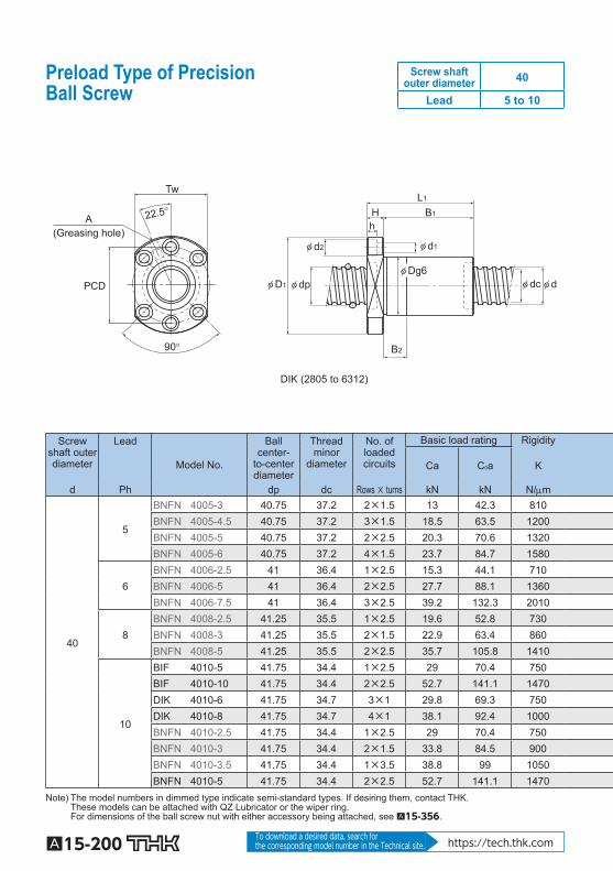
A15-200 To download a desired data, search for the corresponding model number in the Technical site. https://tech.thk.com
Preload Type of PrecisionBall Screw
Screw shaft outer diameter 40
Lead 5 to 10
(Greasing hole)
DIK (2805 to 6312)
A
Tw
PCD
90°
22.5°
φ d2
B2
B1
φ D1 φ dp
φ d1
φ dc
h H
φ Dg6φ d
L1
Screw shaft outer diameter
Lead
Model No.
Ball center-
to-center diameter
Thread minor
diameter
No. of loadedcircuits
Basic load rating Rigidity
Ca C 0 a K
d Ph dp dc Rows × turns kN kN N/m
40
5
BNFN 4005-3 40.75 37.2 2×1.5 13 42.3 810 BNFN 4005-4.5 40.75 37.2 3×1.5 18.5 63.5 1200 BNFN 4005-5 40.75 37.2 2×2.5 20.3 70.6 1320 BNFN 4005-6 40.75 37.2 4×1.5 23.7 84.7 1580
6 BNFN 4006-2.5 41 36.4 1×2.5 15.3 44.1 710 BNFN 4006-5 41 36.4 2×2.5 27.7 88.1 1360 BNFN 4006-7.5 41 36.4 3×2.5 39.2 132.3 2010
8 BNFN 4008-2.5 41.25 35.5 1×2.5 19.6 52.8 730 BNFN 4008-3 41.25 35.5 2×1.5 22.9 63.4 860 BNFN 4008-5 41.25 35.5 2×2.5 35.7 105.8 1410
10
BIF 4010-5 41.75 34.4 1×2.5 29 70.4 750 BIF 4010-10 41.75 34.4 2×2.5 52.7 141.1 1470 DIK 4010-6 41.75 34.7 3×1 29.8 69.3 750 DIK 4010-8 41.75 34.7 4×1 38.1 92.4 1000 BNFN 4010-2.5 41.75 34.4 1×2.5 29 70.4 750 BNFN 4010-3 41.75 34.4 2×1.5 33.8 84.5 900 BNFN 4010-3.5 41.75 34.4 1×3.5 38.8 99 1050 BNFN 4010-5 41.75 34.4 2×2.5 52.7 141.1 1470
Note) The model numbers in dimmed type indicate semi-standard types. If desiring them, contact THK. These models can be attached with QZ Lubricator or the wiper ring. For dimensions of the ball screw nut with either accessory being attached, see A15-356 .

A15-201
Ball Screw
Precision Ball Screw
Options⇒A15-349
(Greasing hole)
BIF
PCD
A
60°
φ d2
B1
φ D1 φ dp
φ d1
φ dc
h H
φ Dg6φ d
L1
(Greasing hole)
PCD
A60°
φ d2
B1
B2
φ D1 φ dp
φ d1
φ dc
h H
φ Dg6φ d
L1
BNFN Unit: mm
Nut dimensions Screw shaft inertial
moment/mm
Nutmass
Shaftmass Outer
diameter Flange
diameter Overalllength Greasing
hole
D D 1 L 1 H B 1 B 2 PCD d 1 ×d 2 ×h Tw A kg•cm 2 /mm kg kg/m 67 101 106 15 91 — 83 9×14×8.5 — M6 1.97×10 -2 2.07 9.06 67 101 126 15 111 — 83 9×14×8.5 — M6 1.97×10 -2 2.37 9.06 67 101 109 15 94 — 83 9×14×8.5 — M6 1.97×10 -2 2.11 9.06 67 101 156 15 141 — 83 9×14×8.5 — M6 1.97×10 -2 2.82 9.06 70 104 90 15 75 — 86 9×14×8.5 — M6 1.97×10 -2 2.05 8.82 70 104 126 15 111 — 86 9×14×8.5 — M6 1.97×10 -2 2.67 8.82 70 104 162 15 147 — 86 9×14×8.5 — M6 1.97×10 -2 3.29 8.82 74 108 106 15 91 — 90 9×14×8.5 — M6 1.97×10 -2 2.69 8.72 74 108 135 15 120 — 90 9×14×8.5 — M6 1.97×10 -2 3.28 8.72 74 108 154 15 139 — 90 9×14×8.5 — M6 1.97×10 -2 3.67 8.72 82 124 103 18 85 — 102 11×17.5×11 — M6 1.97×10 -2 3.69 8.22 82 124 163 18 145 — 102 11×17.5×11 — M6 1.97×10 -2 5.33 8.22 62 104 113 18 95 25 82 11×17.5×11 79 PT 1/8 1.97×10 -2 2.09 8.22 62 104 137 18 119 35 82 11×17.5×11 79 PT 1/8 1.97×10 -2 2.42 8.22 82 124 133 18 115 96 102 11×17.5×11 — M6 1.97×10 -2 4.51 8.22 82 124 170 18 152 133 102 11×17.5×11 — M6 1.97×10 -2 5.52 8.22 82 124 153 18 135 116 102 11×17.5×11 — M6 1.97×10 -2 5.06 8.22 82 124 193 18 175 156 102 11×17.5×11 — M6 1.97×10 -2 6.16 8.22
For model number coding, see A15-248 .

A15-202 To download a desired data, search for the corresponding model number in the Technical site. https://tech.thk.com
Preload Type of PrecisionBall Screw
Screw shaft outer diameter 40
Lead 12 to 40
(Greasing hole)
DIK (2805 to 6312)
A
Tw
PCD
90°
22.5°
φ d2
B2
B1
φ D1 φ dp
φ d1
φ dc
h H
φ Dg6φ d
L1
(Greasing hole)
4-φ d1
PCD
TwA
30°30° B1
B2 B3
N1
L1
H
φ D1φ D2φ Dg6 φ dc φ dφ dp
BLW
Screw shaftouter
diameter
Lead
Model No.
Ball center-
to-center diameter
Thread minor
diameter
No. of loadedcircuits
Basic load rating Rigidity
Ca C 0 a K Outerdiameter
Flangediameter
d Ph dp dc Rows × turns kN kN N/m D D 1 D 2
40
12
BIF 4012-5 42 34.1 1×2.5 33.9 79.2 770 84 126 — BIF 4012-10 42 34.1 2×2.5 61.6 158.8 1490 84 126 — DIK 4012-6 41.75 34.4 3×1 30.6 72.3 790 62 104 — DIK 4012-8 41.75 34.4 4×1 39.2 96.4 1030 62 104 — BNFN 4012-2.5 42 34.1 1×2.5 33.9 79.2 770 84 126 — BNFN 4012-3.5 42 34.1 1×3.5 45.4 110.7 1070 84 126 — BNFN 4012-5 42 34.1 2×2.5 61.6 158.8 1490 84 126 —
16 DIK 4016-4 41.75 34.4 2×1 21.5 68.4 540 62 104 — BNFN 4016-5 42 34.1 2×2.5 61.4 158.8 1500 84 126 —
20 DKN 4020-3 41.75 34.7 3×1 29.4 69.3 750 62 104 — 40 BLW 4040-3.6 41.75 35.2 2×1.8 38.7 99.2 1090 84 121 73
Note) The model numbers in dimmed type indicate semi-standard types. If desiring them, contact THK. These models can be attached with QZ Lubricator or the wiper ring. For dimensions of the ball screw nut with either accessory being attached, see A15-356 . Model BLW cannot be attached with seal.

A15-203
Ball Screw
Precision Ball Screw
Options⇒A15-349
(Greasing hole)
(Greasing hole)
(Greasing hole)
A
Tw
PCD
90°
22.5°
B2
φ D1
φ d2
φ d1
φ dcφ dφ Dg6
φ dp
h B1 H
L1
DKN
BIF
PCD
A60°
φ d2
B1
B2
φ D1 φ dp
φ d1
φ dc
h H
φ Dg6φ d
L1
BNFN
PCD
A
60°
φ d2
B1
φ D1 φ dp
φ d1
φ dc
h H
φ Dg6φ d
L1
Unit: mm
Nut dimensions Screw shaft inertial
moment/mm
Nutmass
Shaftmass Overall
length Greasinghole
L 1 H B 1 B 2 B 3 PCD d 1 d 2 h Tw N 1 A kg•cm 2 /mm kg kg/m 119 18 101 — — 104 11 17.5 11 — — M6 1.97×10 -2 4.36 8.12 191 18 173 — — 104 11 17.5 11 — — M6 1.97×10 -2 6.47 8.12 138 18 120 35 — 82 11 17.5 11 79 — PT 1/8 1.97×10 -2 2.44 8.5 163 18 145 45 — 82 11 17.5 11 79 — PT 1/8 1.97×10 -2 2.78 8.5 155 18 137 118 — 104 11 17.5 11 — — M6 1.97×10 -2 5.42 8.12 179 18 161 142 — 104 11 17.5 11 — — M6 1.97×10 -2 6.12 8.12 227 18 209 190 — 104 11 17.5 11 — — M6 1.97×10 -2 7.52 8.12 120 18 102 30 — 82 11 17.5 11 79 — PT 1/8 1.97×10 -2 2.19 8.83 280 22 258 — — 104 11 17.5 11 — — M6 1.97×10 -2 9.27 8.55 223 18 205 25 — 82 11 17.5 11 79 — PT 1/8 1.97×10 -2 3.61 9.03 191 17 158 54.5 70.5 100 11 — — 87 7 M6 1.97×10 -2 6.16 9.01
For model number coding, see A15-248 .

A15-204 To download a desired data, search for the corresponding model number in the Technical site. https://tech.thk.com
Preload Type of PrecisionBall Screw
Screw shaft outer diameter 45
Lead 6 to 20
(Greasing hole)
PCD
A 60°
BNFN
Screw shaft outer diameter
Lead
Model No.
Ball center-
to-center diameter
Thread minor
diameter
No. of loadedcircuits
Basic load rating Rigidity
Ca C 0 a K
d Ph dp dc Rows × turns kN kN N/m
45
6 BNFN 4506A-2.5 46 41.4 1×2.5 16 49.6 770 BNFN 4506A-5 46 41.4 2×2.5 29 99 1500 BNFN 4506A-7.5 46 41.4 3×2.5 41.2 150 2210
8 BNFN 4508-2.5 46.25 40.6 1×2.5 20.7 59.5 790 BNFN 4508-5 46.25 40.6 2×2.5 37.4 118.6 1540 BNFN 4508-7.5 46.25 40.6 3×2.5 53.1 178.4 2270
10
BNFN 4510-2.5 46.75 39.5 1×2.5 30.7 79.3 830 BNFN 4510-3 46.75 39.5 2×1.5 35.9 95.2 990 BNFN 4510-5 46.75 39.5 2×2.5 55.6 158.8 1610 BNFN 4510-7.5 46.75 39.5 3×2.5 78.8 238.1 2370
12 BNFN 4512-5 47 39.2 2×2.5 65.2 178.4 1640 20 BNFN 4520-1.5 47.7 37.9 1×1.5 44.2 99 690
Note) The model numbers in dimmed type indicate semi-standard types. If desiring them, contact THK.
Model DK Model MDK Models BLK/WGF Model BNT

A15-205
Ball Screw
Precision Ball Screw
φ d2
B1
B2
φ D1 φ dp
φ d1
φ dc
h H
φ Dg6φ d
L1
BNFN
Unit: mm
Nut dimensions Screw shaft inertial
moment/mm Nut
mass Shaftmass Outer
diameter Flange
diameter Overalllength Greasing
hole
D D 1 L 1 H B 1 B 2 PCD d 1 ×d 2 ×h A kg•cm 2 /mm kg kg/m 80 114 89 15 74 — 96 9×14×8.5 PT 1/8 3.16×10 -2 2.59 11.31 80 114 125 15 110 — 96 9×14×8.5 PT 1/8 3.16×10 -2 3.42 11.31 80 114 161 15 146 — 96 9×14×8.5 PT 1/8 3.16×10 -2 4.25 11.31 85 127 116 18 98 — 105 11×17.5×11 PT 1/8 3.16×10 -2 4.09 11.21 85 127 164 18 146 — 105 11×17.5×11 PT 1/8 3.16×10 -2 5.41 11.21 85 127 212 18 194 — 105 11×17.5×11 PT 1/8 3.16×10 -2 6.74 11.21 88 132 141 18 123 104 110 11×17.5×11 PT 1/8 3.16×10 -2 5.26 10.65 88 132 164 18 146 127 110 11×17.5×11 PT 1/8 3.16×10 -2 5.96 10.65 88 132 201 18 183 164 110 11×17.5×11 PT 1/8 3.16×10 -2 7.09 10.65 88 132 261 18 243 224 110 11×17.5×11 PT 1/8 3.16×10 -2 8.92 10.65 90 130 227 18 209 — 110 11×17.5×11 PT 1/8 3.16×10 -2 8.24 10.54 98 142 175 20 155 — 120 11×17.5×11 PT 1/8 3.16×10 -2 8.31 10.37
For model number coding, see A15-248 .
Options⇒A15-349

A15-206 To download a desired data, search for the corresponding model number in the Technical site. https://tech.thk.com
Preload Type of PrecisionBall Screw
Screw shaft outer diameter 50
Lead 5 to 10
(Greasing hole)
DIK (2805 to 6312)
A
Tw
PCD
90°
22.5°
φ d2
B2
B1
φ D1 φ dp
φ d1
φ dc
h H
φ Dg6φ d
L1
Screw shaft outer diameter
Lead
Model No.
Ballcenter-
to-center diameter
Thread minor
diameter
No. of loadedcircuits
Basic load rating Rigidity
Ca C 0 a K
d Ph dp dc Rows × turns kN kN N/m
50
5 ○ BNFN 5005-3 50.75 47.2 2×1.5 14.2 53 970 ○ BNFN 5005-4.5 50.75 47.2 3×1.5 20.2 79.5 1420
8 ○ BNFN 5008-2.5 51.25 45.5 1×2.5 21.6 66.2 860 ○ BNFN 5008-5 51.25 45.5 2×2.5 39.1 132.3 1680 ○ BNFN 5008-7.5 51.25 45.5 3×2.5 55.4 198.9 2470
10
DIK 5010-6 51.75 44.4 3×1 33.9 90.7 940 DIK 5010-8 51.75 44.4 4×1 43.4 120.5 1230 DIK 5010-10 51.75 44.4 5×1 52.5 150.9 1530 ○ BIF 5010-5 51.75 44.4 1×2.5 32 88.2 900 ○ BIF 5010-10 51.75 44.4 2×2.5 58.2 176.4 1750 ○ BNFN 5010-2.5 51.75 44.4 1×2.5 32 88.2 900 ○ BNFN 5010-3 51.75 44.4 2×1.5 37.5 105.8 1080 ○ BNFN 5010-3.5 51.75 44.4 1×3.5 42.8 123.5 1240 ○ BNFN 5010-5 51.75 44.4 2×2.5 58.2 176.4 1750 ○ BNFN 5010-7.5 51.75 44.4 3×2.5 82.5 264.6 2580
Note) The model numbers in dimmed type indicate semi-standard types. If desiring them, contact THK. Those models marked with ○ can be attached with QZ Lubricator or the wiper ring. For dimensions of the ball screw nut with either accessory being attached, see A15-356 .

A15-207
Ball Screw
Precision Ball Screw
(Greasing hole)
BIF
PCD
A
60°
φ d2
B1
φ D1 φ dp
φ d1
φ dc
hH
φDg6φ d
L1
(Greasing hole)
PCD
A60°
φ d2
B1
B2
φ D1 φ dp
φ d1
φ dc
h H
φ Dg6φ d
L1
BNFN
Unit: mm
Nut dimensions Screw shaft inertial
moment/mm
Nutmass
Shaftmass Outer
diameter Flange
diameter Overalllength Greasing
hole
D D 1 L 1 H B 1 B 2 PCD d 1 ×d 2 ×h Tw A kg•cm 2 /mm kg kg/m 80 114 108 15 93 — 96 9×14×8.5 — PT 1/8 4.82×10 -2 2.71 14.42 80 114 128 15 113 — 96 9×14×8.5 — PT 1/8 4.82×10 -2 3.12 14.42 87 129 109 18 91 — 107 11×17.5×11 — PT 1/8 4.82×10 -2 3.8 14.0 87 129 157 18 139 — 107 11×17.5×11 — PT 1/8 4.82×10 -2 5.08 14.0 87 129 205 18 187 — 107 11×17.5×11 — PT 1/8 4.82×10 -2 6.35 14.0 72 123 114 18 96 30 101 11×17.5×11 92 PT 1/8 4.82×10 -2 2.65 13.38 72 123 137 18 119 35 101 11×17.5×11 92 PT 1/8 4.82×10 -2 3.03 13.38 72 123 160 18 142 45 101 11×17.5×11 92 PT 1/8 4.82×10 -2 3.41 13.38 93 135 103 18 85 — 113 11×17.5×11 — PT 1/8 4.82×10 -2 4.31 13.38 93 135 163 18 145 — 113 11×17.5×11 — PT 1/8 4.82×10 -2 6.26 13.38 93 135 133 18 115 96 113 11×17.5×11 — PT 1/8 4.82×10 -2 5.28 13.38 93 135 170 18 152 133 113 11×17.5×11 — PT 1/8 4.82×10 -2 6.49 13.38 93 135 153 18 135 116 113 11×17.5×11 — PT 1/8 4.82×10 -2 5.94 13.38 93 135 193 18 175 156 113 11×17.5×11 — PT 1/8 4.82×10 -2 7.24 13.38 93 135 253 18 235 216 113 11×17.5×11 — PT 1/8 4.82×10 -2 9.19 13.38
For model number coding, see A15-248 .
Options⇒A15-349

A15-208 To download a desired data, search for the corresponding model number in the Technical site. https://tech.thk.com
Preload Type of PrecisionBall Screw
Screw shaft outer diameter 50
Lead 12 to 50
(Greasing hole)
DIK (2805 to 6312)
A
Tw
PCD
90°
22.5°
φ d2
B2
B1
φ D1 φ dp
φ d1
φ dc
h H
φ Dg6φ d
L1
(Greasing hole)
4-φ d1
PCD
TwA
30°30° B1
B2 B3
N1
L1
H
φ D1φ D2φ Dg6 φ dc φ dφ dp
BLW
Screw shaft outer diameter
Lead
Model No.
Ball center-
to-center diameter
Thread minor
diameter
No. of loadedcircuits
Basic load rating Rigidity
Ca C 0 a K Outerdiameter
Flangediameter
d Ph dp dc Rows × turns kN kN N/m D D 1 D 2
50
12
DIK 5012-6 52.25 43.3 3×1 45.8 113 970 75 129 — DIK 5012-8 52.25 43.3 4×1 58.6 150.6 1270 75 129 —
○ BNFN 5012-2.5 52.25 43.3 1×2.5 43.4 109.8 930 100 146 — ○ BNFN 5012-3.5 52.25 43.3 1×3.5 58 153.9 1280 100 146 — ○ BNFN 5012-5 52.25 43.3 2×2.5 78.8 220.5 1810 100 146 —
16
DIK 5016-4 52.25 43.3 2×1 32.3 75.5 660 75 129 — DIK 5016-6 52.25 43.3 3×1 45.7 113.3 970 75 129 —
○ BNFN 5016-2.5 52.7 42.9 1×2.5 72.6 183.3 1230 105 152 — ○ BNFN 5016-5 52.7 42.9 2×2.5 132.3 366.5 2360 105 152 —
20 DKN 5020-3 52.25 43.6 3×1 44.2 108.8 930 75 129 —
○ BNFN 5020-2.5 52.7 42.9 1×2.5 72.5 183.3 1230 105 152 — 50 BLW 5050-3.6 52.2 44.1 2×1.8 57.8 155 1340 106 149 90
Note) The model numbers in dimmed type indicate semi-standard types. If desiring them, contact THK. Those models marked with ○ can be attached with QZ Lubricator or the wiper ring. For dimensions of the ball screw nut with either accessory being attached, see A15-356 . Model BLW cannot be attached with seal.