Screw Jack Tutorial
16
Tutorial on Screw Jack Hareesha N G Asst. Professor Dept of Aeronautical Engg Dayananda Sagar College of Engg Bangalore-78 3/26/2013 1 Hareesha N Gowda, DSCE, Blore-78
-
Upload
hareesha-n-g -
Category
Documents
-
view
238 -
download
6
description
Screw Jack Tutorial
Transcript of Screw Jack Tutorial

Tutorial on Screw Jack
Hareesha N G
Asst. Professor
Dept of Aeronautical Engg
Dayananda Sagar College of Engg
Bangalore-78
3/26/2013 1Hareesha N Gowda, DSCE,
Blore-78

Assembly Drawings1. Screw Jack
3/26/2013 2Hareesha N Gowda, DSCE,
Blore-78
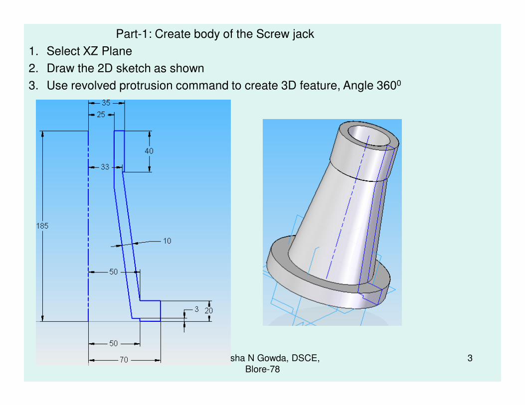
Part-1: Create body of the Screw jack
1. Select XZ Plane
2. Draw the 2D sketch as shown
3. Use revolved protrusion command to create 3D feature, Angle 3600
3/26/2013 3Hareesha N Gowda, DSCE,
Blore-78

Part-1: Create body of the Screw jack
• Create fillets as shown in Fig. 1, 2, and 3
3/26/2013 Hareesha N Gowda, DSCE,
Blore-78
4
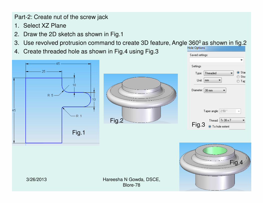
Part-2: Create nut of the screw jack
1. Select XZ Plane
2. Draw the 2D sketch as shown in Fig.1
3. Use revolved protrusion command to create 3D feature, Angle 3600 as shown in fig.2
4. Create threaded hole as shown in Fig.4 using Fig.3
3/26/2013 5Hareesha N Gowda, DSCE,
Blore-78
Fig.1
Fig.2
Fig.4
Fig.3

Part-3: Create Screw Spindle of the screw jack (Step-1)
1. Select XZ Plane
2. Draw the 2D sketch as shown in Fig.1
3. Use revolved protrusion command to create 3D
feature, Angle 3600 as shown in Fig.2
3/26/2013 6Hareesha N Gowda, DSCE,
Blore-78
Fig.1Fig.2

Part-3: Create Screw Spindle of the screw jack ( Step-2)
1. Select XZ Plane
2. Draw the 2D sketch as shown
3. Use Cut out command to create Symmetric through hole
3/26/2013 7Hareesha N Gowda, DSCE,
Blore-78
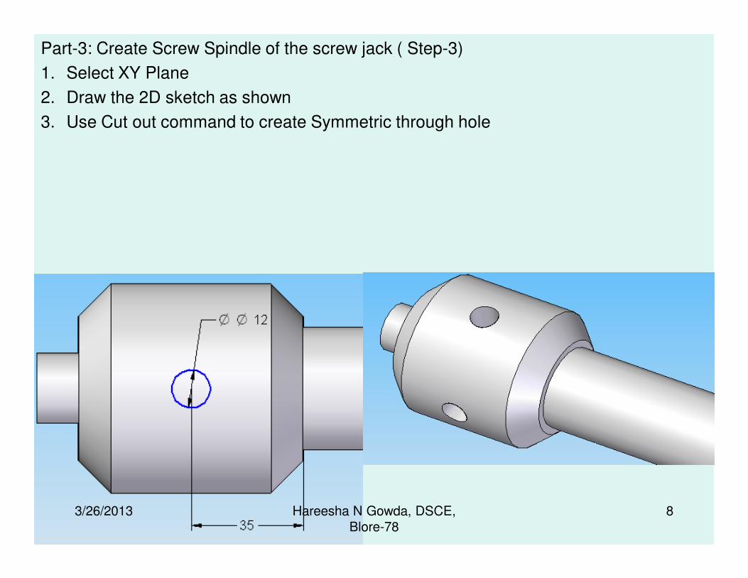
Part-3: Create Screw Spindle of the screw jack ( Step-3)
1. Select XY Plane
2. Draw the 2D sketch as shown
3. Use Cut out command to create Symmetric through hole
3/26/2013 8Hareesha N Gowda, DSCE,
Blore-78

Part-3: Create Screw Spindle of the screw jack ( Step-4)
1. Select the Plane as shown, use threaded hole command, Go to hole option,
set the parameters as shown in dialogue box and create threaded hole as shown
in fig.1
3/26/2013 9Hareesha N Gowda, DSCE,
Blore-78
fig.1

Part-4: Create CUP of the screw jack (Step-1)
1. Select XZ Plane
2. Draw the 2D sketch as shown
3. Use revolved protrusion command to create 3D feature, angle 3600
3/26/2013 10Hareesha N Gowda, DSCE,
Blore-78

Part-4: Create CUP of the screw jack (Step-2)
1. Select XZ Plane
2. Draw the 2D sketch as shown
3. Use Cut out command to create the profile as shown
4. Use Circular pattern to create remaining features as shown
3/26/2013 11Hareesha N Gowda, DSCE,
Blore-78

Part-5: Create Special washer of the screw jack
1. Select XZ Plane
2. Draw the 2D sketch as shown
3. Use revolved protrusion command to create 3D feature, angle 3600
3/26/2013 12Hareesha N Gowda, DSCE,
Blore-78
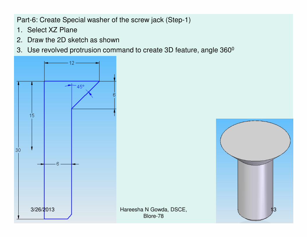
Part-6: Create Special washer of the screw jack (Step-1)
1. Select XZ Plane
2. Draw the 2D sketch as shown
3. Use revolved protrusion command to create 3D feature, angle 3600
3/26/2013 13Hareesha N Gowda, DSCE,
Blore-78

Part-6: Create Special washer of the screw jack (Step-2)
1. Select top surface as shown
2. Draw the 2D sketch as shown
3. Use cut out command to create 3D feature, depth 3mm
3/26/2013 14Hareesha N Gowda, DSCE,
Blore-78

Part-6: Create Special washer of the screw jack (Step-3)
1. Select cylindrical surface as shown
2. Use thread command to create thread feature with the parameters as shown below
3/26/2013 15Hareesha N Gowda, DSCE,
Blore-78

Part-7: Create Tommy Bar of the screw jack
• Select XZ Plane
• Draw the 2D sketch as shown
• Use revolved protrusion command to create 3D feature, angle 3600
3/26/2013 16Hareesha N Gowda, DSCE,
Blore-78