
Wind Turbine Gearbox Lubrication: Performance, Selection ...
Screw Jack Systems
XII
www.zimm.at
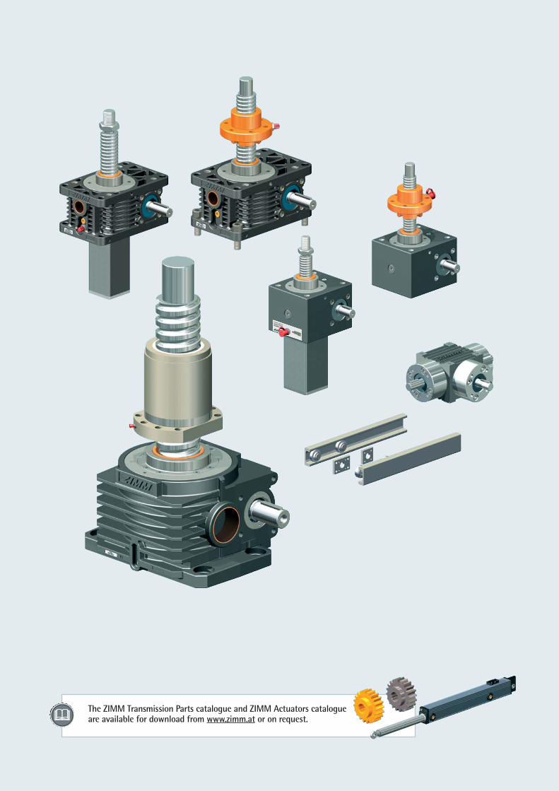
The ZIMM Transmission Parts catalogue and ZIMM Actuators catalogueare available for download from www.zimm.at or on request.
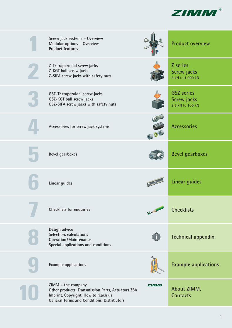
Product overview
Z seriesScrew jacks5 kN to 1,000 kN
GSZ seriesScrew jacks2.5 kN to 100 kN
Screw jack systems – OverviewModular options – OverviewProduct features
Z-Tr trapezoidal screw jacksZ-KGT ball screw jacksZ-SIFA screw jacks with safety nuts
GSZ-Tr trapezoidal screw jacksGSZ-KGT ball screw jacksGSZ-SIFA screw jacks with safety nuts
Accessories for screw jack systems
Bevel gearboxes
Checklists for enquiries
Design adviceSelection, calculationsOperation/MaintenanceSpecial applications and conditions
Example applications
ZIMM – the companyOther products: Transmission Parts, Actuators ZSA Imprint, Copyright, How to reach us General Terms and Conditions, Distributors
Accessories
Bevel gearboxes
Linear guides
Technical appendix
About ZIMM,Contacts
Linear guides
123456789
101
Checklists
Example applications
© by ZIMM Austria 20132
Product overview1
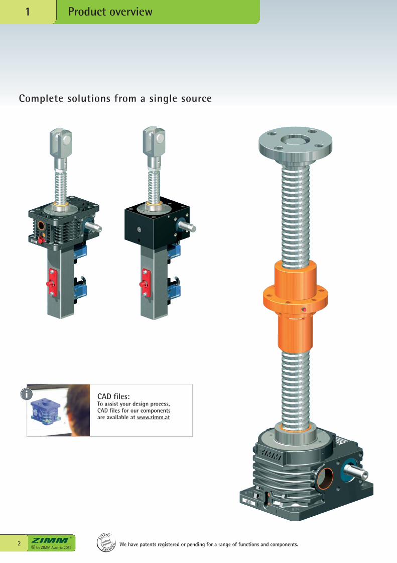
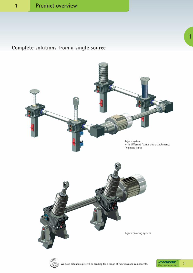
Complete solutions from a single source
We have patents registered or pending for a range of functions and components.
PA
TENT
P E N D I NG
zum Patent
angemeldet
CAD files:To assist your design process,CAD files for our components are available at www.zimm.at
3© by ZIMM Austria 2013
Product overview
1
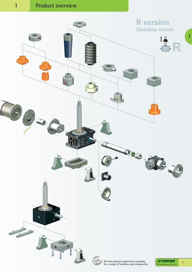
Complete solutions from a single source
1
4-jack system with different fixings and attachments (example only)
2-jack pivoting system
PA
TENT
P E N D I NG
zum Patent
angemeldet We have patents registered or pending for a range of functions and components.
S translating screwR rotating screw
Z-KGTwith ball screw
Z-SIFAwith safety nut
GSZ-Trwith trapezoidal screw
GSZ-KGTwith ball screw
16x4 16x4
16x516x10
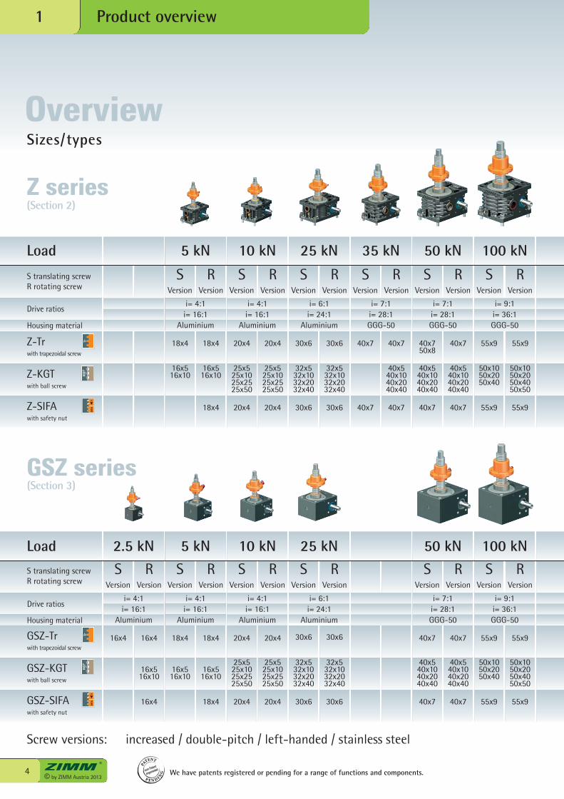
Screw versions: increased / double-pitch / left-handed / stainless steel
i= 4:1i= 16:1
Z-Trwith trapezoidal screw
Drive ratios
Drive ratios
S Version
RVersion
18x4 18x4 20x4 20x4 30x6 30x6 40x7 40x7 40x750x8
40x7 55x9 55x9
16x516x10
16x516x10
25x525x1025x2525x50
25x525x1025x2525x50
32x532x1032x2032x40
32x532x1032x2032x40
40x540x1040x2040x40
40x540x1040x2040x40
40x540x1040x2040x40
50x1050x2050x40
50x1050x2050x4050x50
18x4 20x4 20x4 30x6 30x6 40x7 40x7 40x7 40x7 55x9 55x9
i= 4:1i= 16:1
18x4 18x4
16x516x10
16x516x10
i= 4:1i= 16:1
S Version
RVersion
i= 4:1i= 16:1
20x4 20x4
25x525x1025x2525x50
25x525x1025x2525x50
i= 4:1i= 16:1
S Version
RVersion
i= 6:1i= 24:1
30x6 30x6
32x532x1032x2032x40
32x532x1032x2032x40
i= 6:1i= 24:1
S Version
RVersion
i= 7:1i= 28:1
S Version
RVersion
i= 7:1i= 28:1
40x7 40x7
40x540x1040x2040x40
40x540x1040x2040x40
i= 7:1i= 28:1
S Version
RVersion
i= 9:1i= 36:1
Aluminium Aluminium Aluminium GGG-50 GGG-50 GGG-50
55x9 55x9
50x1050x2050x40
50x1050x2050x4050x50
GSZ-SIFAwith safety nut
16x4 18x4 20x4 20x4 30x6 30x6 40x7 40x7 55x9 55x9
i= 9:1i= 36:1
S translating screwR rotating screw
S Version
RVersion
S Version
RVersion
S Version
RVersion
S Version
RVersion
S Version
RVersion
S Version
RVersion
© by ZIMM Austria 20134
Load 5 kN 10 kN 25 kN 35 kN 50 kN 100 kN
Load 2.5 kN 5 kN 10 kN 25 kN 50 kN 100 kN
Product overview1
Sizes/types
We have patents registered or pending for a range of functions and components.
PA
TENT
P E N D I NG
zum Patent
angemeldet
Housing material
Aluminium Aluminium Aluminium Aluminium GGG-50 GGG-50Housing material
GSZ series(Section 3)
Z series(Section 2)
Overview
S Version
RVersion
S Version
RVersion
S Version
RVersion
S Version
RVersion
S Version
RVersion
S Version
RVersion
i= 9:1i= 36:1
i= 10.66:1i= 32:1
i= 10.66:1i= 32:1
i= 10.66:1i= 32:1
i= 13.33:1i= 40:1
i= 13.33:1i= 40:1
60x9 60x9 80x16 80x16 100x16 100x16 120x16 120x16 140x20 140x20 160x20 160x20
63x1063x2063x4063x60
63x1063x2063x4063x60
80x1080x2080x4080x60
80x1080x2080x4080x60
100x20100x40100x60100x80
100x20100x40100x60100x80
125x25125x40125x60125x80
125x25125x40125x60125x80
140x25140x40140x60140x80
140x25140x40140x60140x80
160x25160x40160x60160x80
160x25160x40160x60160x80
60x9 60x9 80x16 80x16 100x16 100x16 120x16 120x16 140x20 140x20 160x20 160x20
GGG-50 GGG-50 GGG-50 GGG-50 GGG-50 GGG-50
5© by ZIMM Austria 2013
Product overview
1
1
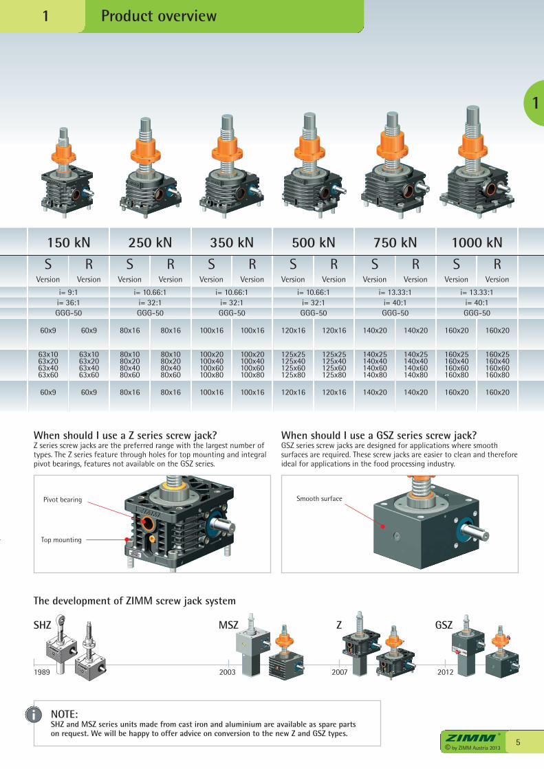
150 kN 250 kN 350 kN 500 kN 750 kN 1000 kN
When should I use a Z series screw jack?Z series screw jacks are the preferred range with the largest number oftypes. The Z series feature through holes for top mounting and integralpivot bearings, features not available on the GSZ series.
Pivot bearing
Top mounting
Smooth surface
When should I use a GSZ series screw jack?GSZ series screw jacks are designed for applications where smooth surfaces are required. These screw jacks are easier to clean and thereforeideal for applications in the food processing industry.
NOTE:SHZ and MSZ series units made from cast iron and aluminium are available as spare partson request. We will be happy to offer advice on conversion to the new Z and GSZ types.
The development of ZIMM screw jack system
1989 2003 2007 2012
MSZ ZSHZ GSZ
Product overview1
We have patents registered or pendingfor a range of functions and components.
PA
TENT
P E N D I NG
zum Patent
angemeldet
© by ZIMM Austria 20136
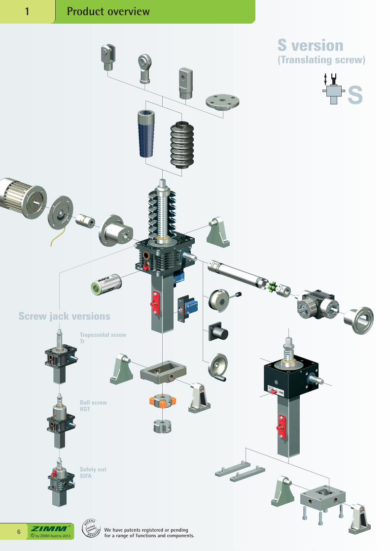
Trapezoidal screwTr
Ball screwKGT
Safety nutSIFA
Screw jack versions
S version(Translating screw)
7© by ZIMM Austria 2013
Product overview
1
1
We have patents registered or pendingfor a range of functions and components.
PA
TENT
P E N D I NG
zum Patent
angemeldet
R version(Rotating screw)
© by ZIMM Austria 20138
Product overview1
We have patents registered or pending for a range of functions and components.
PA
TENT
P E N D I NG
zum Patent
angemeldet
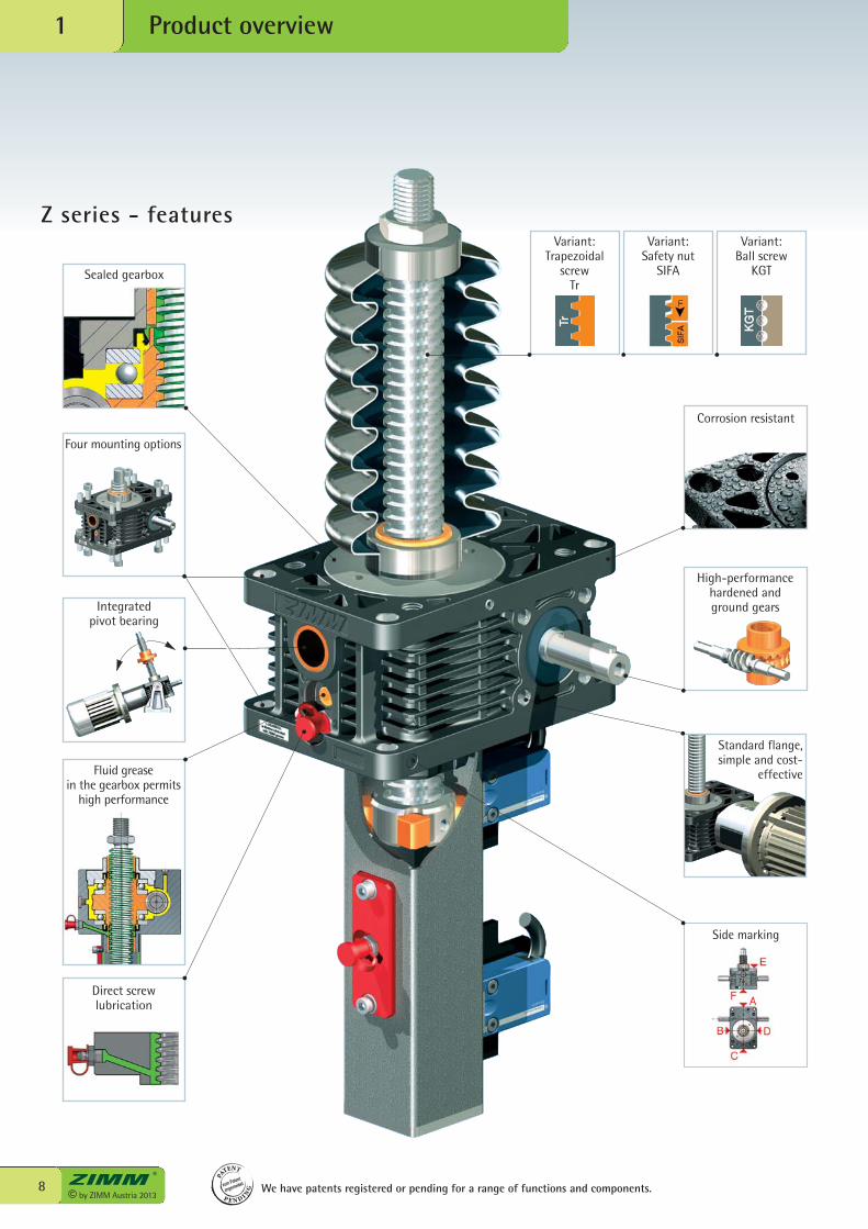
Z series - featuresVariant:
Trapezoidalscrew
Tr
Variant:Safety nut
SIFA
Variant:Ball screw
KGT
High-performancehardened and ground gears
Corrosion resistant
Standard flange,simple and cost-
effective
Side marking
Direct screw lubrication
Fluid grease in the gearbox permits
high performance
Integrated pivot bearing
Sealed gearbox
Four mounting options
9© by ZIMM Austria 2013
Product overview
1
1
PA
TENT
P E N D I NG
zum Patent
angemeldet We have patents registered or pending for a range of functions and components.
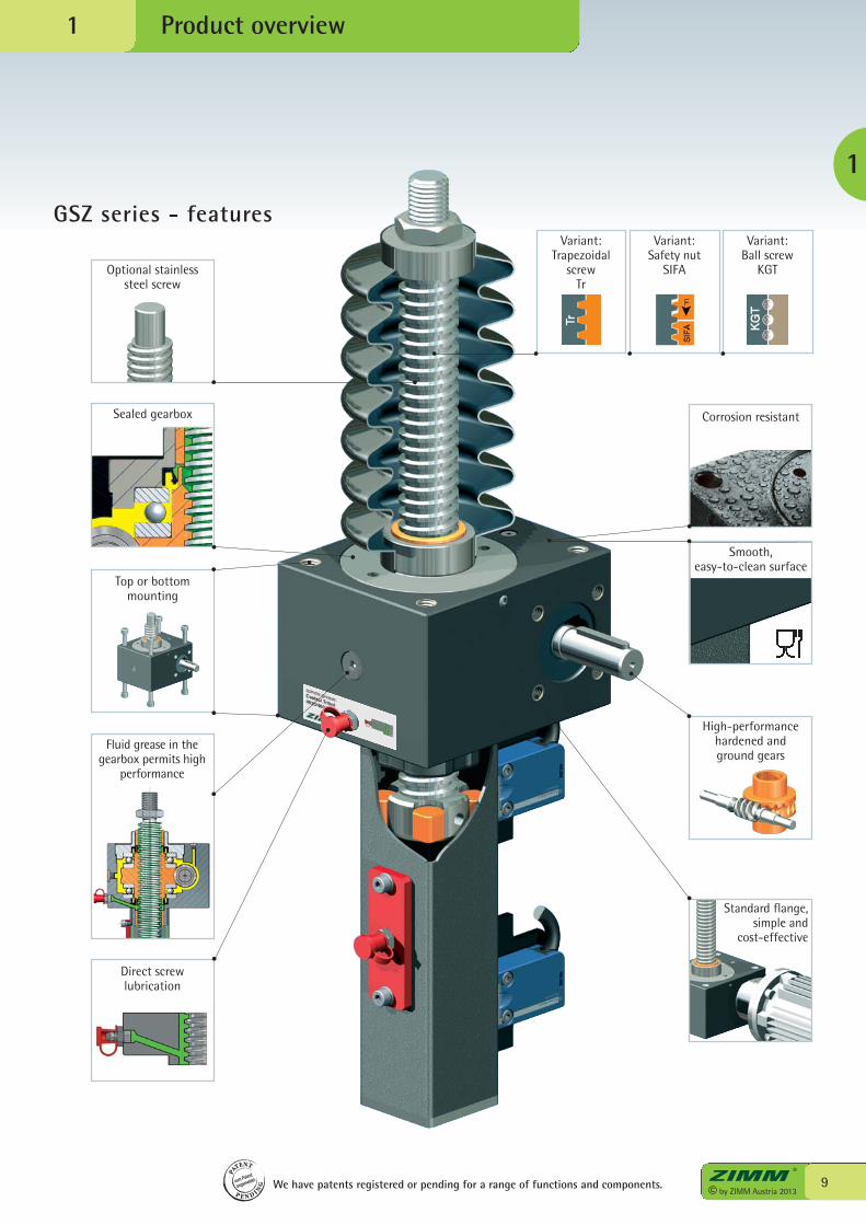
Standard flange,simple and
cost-effective
Fluid grease in the gearbox permits high
performance
Top or bottom mounting
Direct screw lubrication
Optional stainless steel screw
High-performancehardened and ground gears
Corrosion resistantSealed gearbox
GSZ series - features
Smooth, easy-to-clean surface
Variant:Trapezoidal
screwTr
Variant:Safety nut
SIFA
Variant:Ball screw
KGT

© by ZIMM Austria 201310
product and environment...
Festival stage, Bregenz

11© by ZIMM Austria 2013
1
in harmony!
Bodensee, Hard
© by ZIMM Austria 201312
Z series screw jacks, 5 kN - 1,000 kN2
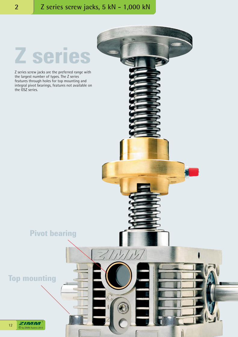
Z series
Pivot bearing
Top mounting
Z series screw jacks are the preferred range withthe largest number of types. The Z seriesfeatures through holes for top mounting andintegral pivot bearings, features not available onthe GSZ series.
13© by ZIMM Austria 2013
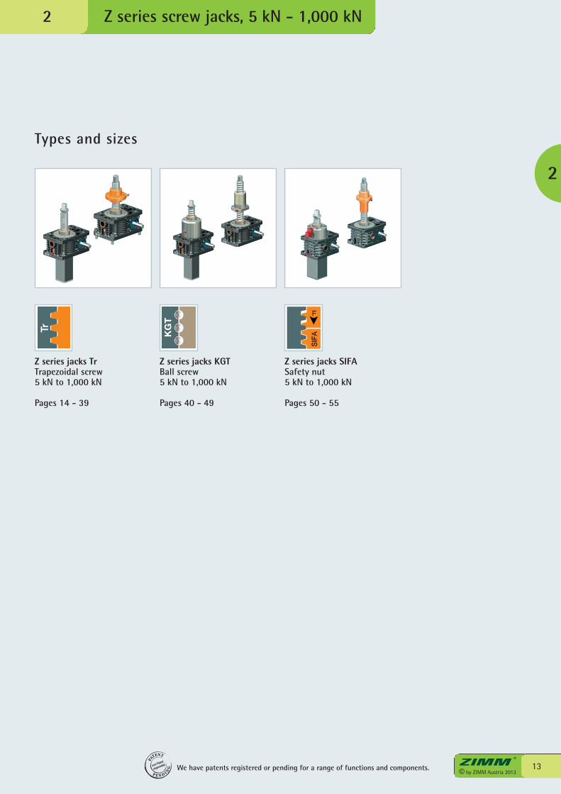
Types and sizes
Z series screw jacks, 5 kN - 1,000 kN
2
2
Z series jacks TrTrapezoidal screw5 kN to 1,000 kN
Pages 14 - 39
Z series jacks KGTBall screw5 kN to 1,000 kN
Pages 40 - 49
Z series jacks SIFASafety nut 5 kN to 1,000 kN
Pages 50 - 55
We have patents registered or pending for a range of functions and components.
PA
TENT
P E N D I NG
zum Patent
angemeldet
KG
T

© by ZIMM Austria 201314
[kN]
0 10 20 30 40 50 60 70 80 90 100
5
4
3
2
1
Z-5-S translating screw 5 kN
Z series screw jacks, SN+SL2
*Hinged bearing plate KAR, fitted on face F (below).
Escape/rotation protection
61+stroke
Rotation protectionwith ES and KAR*
140+stroke
Rotation protection,with limit switch set
ES119+stroke
6)Protective tube length SRO with Tr 18x4 screw
Trapezoidal screwTr 18x4
Duty cycle thermal limit, for S+RThese curves are forguidance understandard industrialconditions (ambienttemperature etc.) andcorrect maintenance(lubrication etc.). The max. input drivetorques for optimumservice life are at theright page - technicaldata (1500 rpm)
% duty cycle/10 min at 20°C
Type
Z-5-SNZ-5-SLZ-5-RNZ-5-RL
Speed
Normal
Low
Normal
Low
i
4:1
16:1
4:1
16:1
Stroke per drive shaft
rotation5)
1.00 mm
0.25 mm
1.00 mm
0.25 mm
Version
Translating
screw
Rotating
screw
Standardscrew2)
Tr 18x4
Tr 18x4
Bellows FB X/Y X/Y X/Y X/Y X/Ywithout bellows FB 50/94 70/114 98/142 100/144 98/142Z-5-FB-265 83/127 83/127 131/175 133/177 111/155Z-5-FB-500 148/192 148/192 196/240 198/242 176/220Z-5-FB-800 168/212 168/212 216/260 218/262 196/240
*with bellows fixing ring Z-5-FBR
Standard ratios
1)Fitting height for 0-stroke, with Tr 18x4 screw
Standard screw end*
Fixing flange BF
Forked endGK*
Rod endKGK*
Pivot bearingendSLK
Without escape/rotation protection
46+stroke
All dimensions in mm
KGT:% duty cycle2 times to4 times higher
Opening forprotective tube SRO,square 41x41 orround Ø 50
500 rpm1000 rpm
1500 rpm
1800 rpm
3000 rpm
UNIQUE:Screw lubricationduring operation
Trapezoidal screwTr
Full static nominal load max. load: see Section 8
F
Screw jack mounting
F F
32H7/1.5 deep
M6/8 deepM8/13 deep (4x) 16H9/15 deep
M8/13 deep (4x)
M8/13 deep (8x)
SRO
6)
Leng
th
Fitt
ing
heig
ht Y
Scre
w le
ngth
Ove
rall
heig
ht
1)
15© by ZIMM Austria 2013
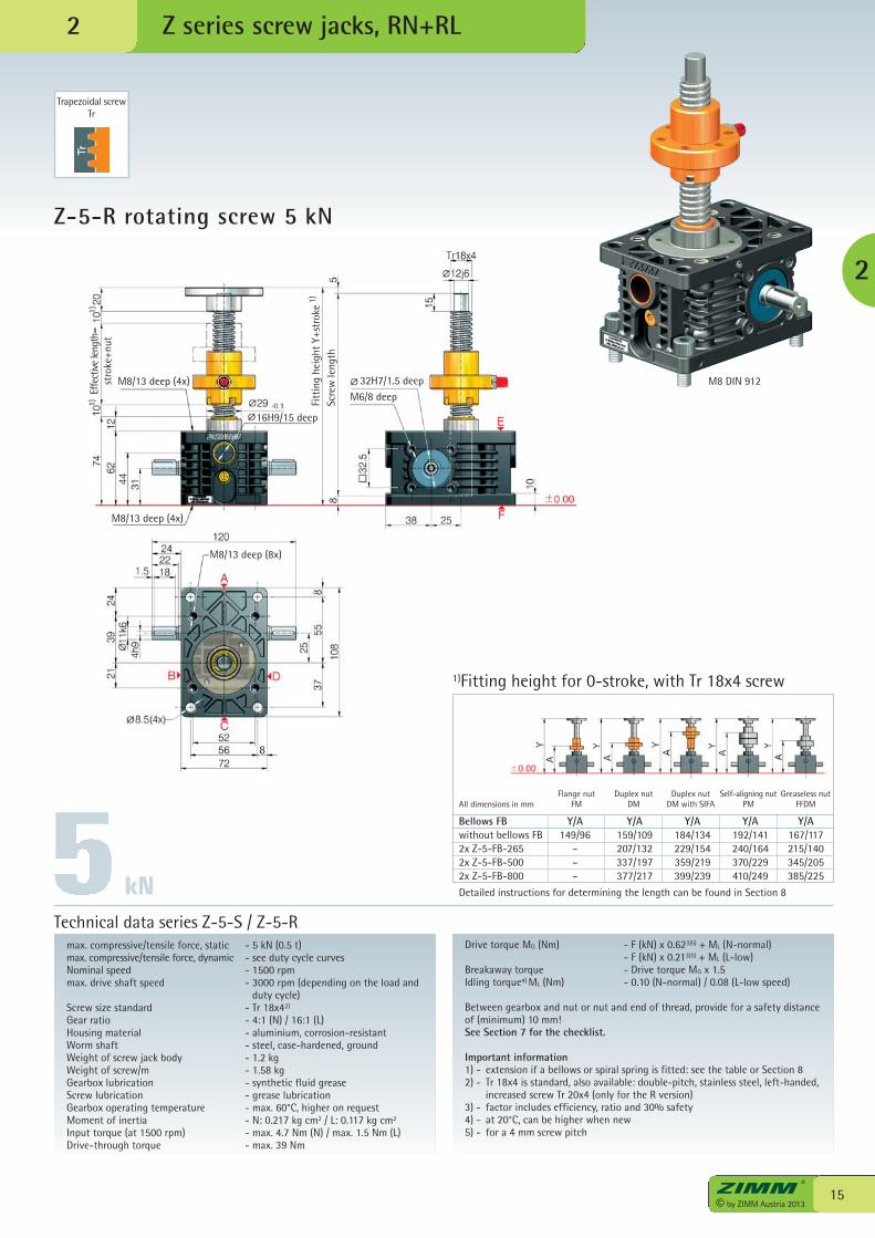
Z-5-R rotating screw 5 kN
Z series screw jacks, RN+RL
max. compressive/tensile force, static - 5 kN (0.5 t)max. compressive/tensile force, dynamic - see duty cycle curvesNominal speed - 1500 rpmmax. drive shaft speed - 3000 rpm (depending on the load and
duty cycle)Screw size standard - Tr 18x42)
Gear ratio - 4:1 (N) / 16:1 (L)Housing material - aluminium, corrosion-resistantWorm shaft - steel, case-hardened, groundWeight of screw jack body - 1.2 kgWeight of screw/m - 1.58 kgGearbox lubrication - synthetic fluid greaseScrew lubrication - grease lubricationGearbox operating temperature - max. 60°C, higher on requestMoment of inertia - N: 0.217 kg cm2 / L: 0.117 kg cm2
Input torque (at 1500 rpm) - max. 4.7 Nm (N) / max. 1.5 Nm (L)Drive-through torque - max. 39 Nm
Drive torque MG (Nm) - F (kN) x 0.623)5) + ML (N-normal) - F (kN) x 0.213)5) + ML (L-low)Breakaway torque - Drive torque MG x 1.5Idling torque4) ML (Nm) - 0.10 (N-normal) / 0.08 (L-low speed)
Between gearbox and nut or nut and end of thread, provide for a safety distanceof (minimum) 10 mm!See Section 7 for the checklist.
Important information1) - extension if a bellows or spiral spring is fitted: see the table or Section 82) - Tr 18x4 is standard, also available: double-pitch, stainless steel, left-handed,
increased screw Tr 20x4 (only for the R version)3) - factor includes efficiency, ratio and 30% safety4) - at 20°C, can be higher when new5) - for a 4 mm screw pitch
Technical data series Z-5-S / Z-5-R
kN
Bellows FB Y/A Y/A Y/A Y/A Y/Awithout bellows FB 149/96 159/109 184/134 192/141 167/1172x Z-5-FB-265 – 207/132 229/154 240/164 215/1402x Z-5-FB-500 – 337/197 359/219 370/229 345/2052x Z-5-FB-800 – 377/217 399/239 410/249 385/225
Detailed instructions for determining the length can be found in Section 8
1)Fitting height for 0-stroke, with Tr 18x4 screw
Flange nutFM
Duplex nutDM
Duplex nutDM with SIFA
Self-aligning nutPM
Greaseless nutFFDMAll dimensions in mm
2
Trapezoidal screwTr
M8 DIN 912
2
Scre
w le
ngth
Fitt
ing
heig
ht Y
+str
oke
Effe
ctiv
e le
ngth
=st
roke
+nut
32H7/1.5 deepM6/8 deep
M8/13 deep (4x)
M8/13 deep (8x)
M8/13 deep (4x)
1)
1)1)
16H9/15 deep
© by ZIMM Austria 201316
[kN]
0 10 20 30 40 50 60 70 80 90 100
10
8
6
4
2
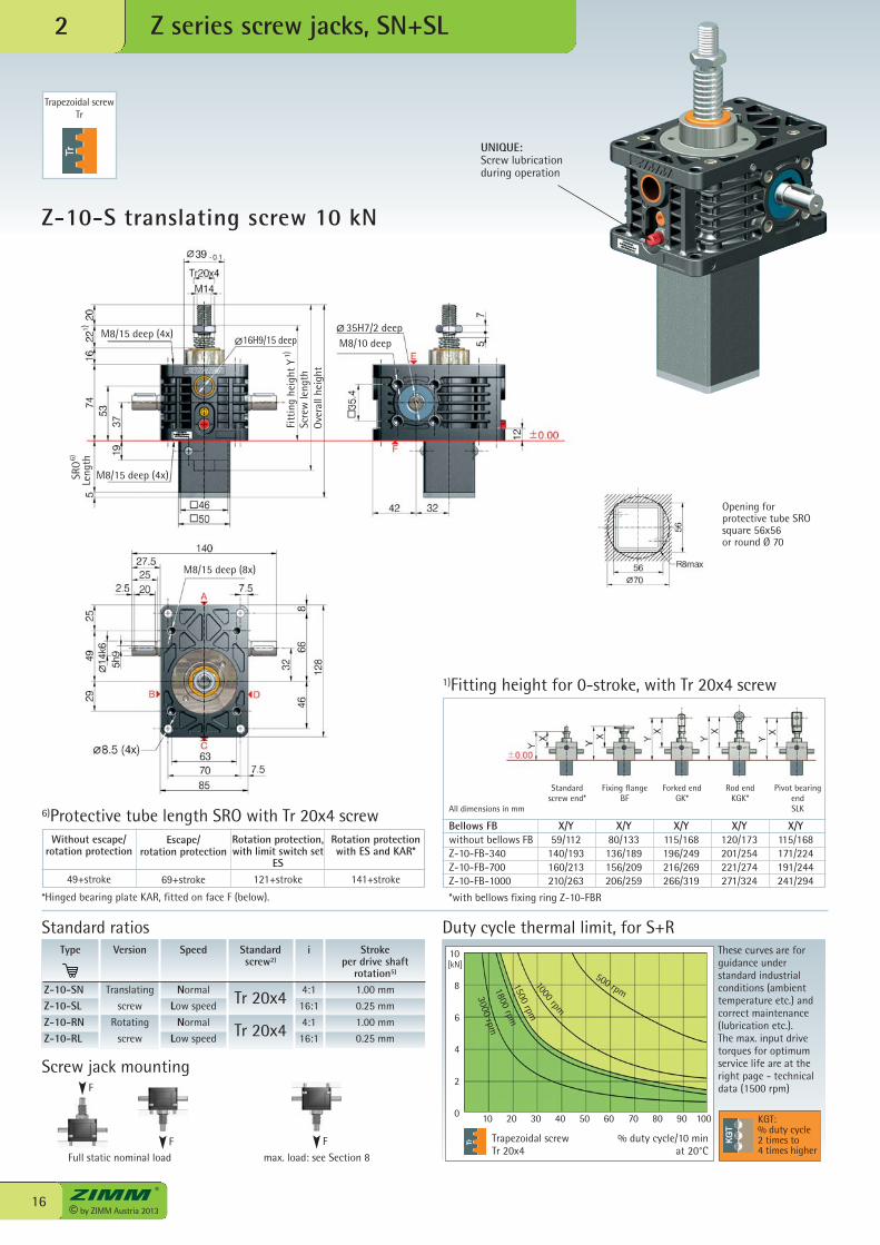
Z-10-S translating screw 10 kN
Z series screw jacks, SN+SL2
Trapezoidal screwTr 20x4
Duty cycle thermal limit, for S+RThese curves are forguidance understandard industrialconditions (ambienttemperature etc.) andcorrect maintenance(lubrication etc.). The max. input drivetorques for optimumservice life are at theright page - technicaldata (1500 rpm)
% duty cycle/10 min at 20°C
Type
Z-10-SNZ-10-SLZ-10-RNZ-10-RL
Speed
Normal
Low speed
Normal
Low speed
i
4:1
16:1
4:1
16:1
Stroke per drive shaft
rotation5)
1.00 mm
0.25 mm
1.00 mm
0.25 mm
Version
Translating
screw
Rotating
screw
Standardscrew2)
Tr 20x4
Tr 20x4
Standard ratios
KGT:% duty cycle2 times to4 times higher
Opening for protective tube SRO square 56x56or round Ø 70
UNIQUE:Screw lubricationduring operation
Trapezoidal screwTr
500 rpm
1000 rpm
1500 rpm
1800 rpm
3000 rpm
*Hinged bearing plate KAR, fitted on face F (below).
6)Protective tube length SRO with Tr 20x4 screwBellows FB X/Y X/Y X/Y X/Y X/Ywithout bellows FB 59/112 80/133 115/168 120/173 115/168Z-10-FB-340 140/193 136/189 196/249 201/254 171/224Z-10-FB-700 160/213 156/209 216/269 221/274 191/244Z-10-FB-1000 210/263 206/259 266/319 271/324 241/294
*with bellows fixing ring Z-10-FBR
1)Fitting height for 0-stroke, with Tr 20x4 screw
Standard screw end*
Fixing flange BF
Forked endGK*
Rod endKGK*
Pivot bearingendSLKAll dimensions in mm
Rotation protection,with limit switch set
ES121+stroke
Escape/rotation protection
69+stroke
Without escape/rotation protection
49+stroke
Rotation protectionwith ES and KAR*
141+stroke
35H7/2 deepM8/10 deep
M8/15 deep (4x) 16H9/15 deep
M8/15 deep (4x)
M8/15 deep (8x)
SRO
Leng
th
Fitt
ing
heig
ht Y
Scre
w le
ngth
Ove
rall
heig
ht
6)
1)
1)
Full static nominal load max. load: see Section 8
F
Screw jack mounting
F F
17© by ZIMM Austria 2013
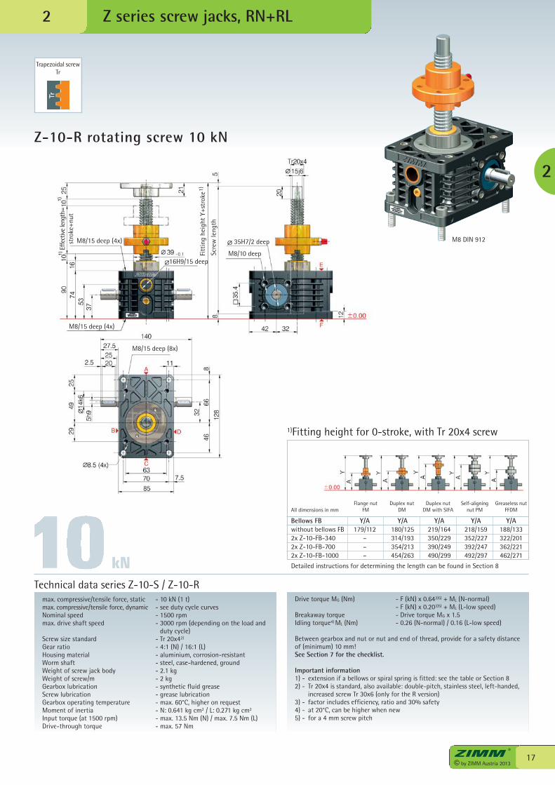
Z-10-R rotating screw 10 kN
Z series screw jacks, RN+RL
max. compressive/tensile force, static - 10 kN (1 t)max. compressive/tensile force, dynamic - see duty cycle curvesNominal speed - 1500 rpmmax. drive shaft speed - 3000 rpm (depending on the load and
duty cycle)Screw size standard - Tr 20x42)
Gear ratio - 4:1 (N) / 16:1 (L)Housing material - aluminium, corrosion-resistantWorm shaft - steel, case-hardened, groundWeight of screw jack body - 2.1 kgWeight of screw/m - 2 kgGearbox lubrication - synthetic fluid greaseScrew lubrication - grease lubricationGearbox operating temperature - max. 60°C, higher on requestMoment of inertia - N: 0.641 kg cm2 / L: 0.271 kg cm2
Input torque (at 1500 rpm) - max. 13.5 Nm (N) / max. 7.5 Nm (L)Drive-through torque - max. 57 Nm
Drive torque MG (Nm) - F (kN) x 0.643)5) + ML (N-normal) - F (kN) x 0.203)5) + ML (L-low speed)Breakaway torque - Drive torque MG x 1.5Idling torque4) ML (Nm) - 0.26 (N-normal) / 0.16 (L-low speed)
Between gearbox and nut or nut and end of thread, provide for a safety distanceof (minimum) 10 mm!See Section 7 for the checklist.
Important information1) - extension if a bellows or spiral spring is fitted: see the table or Section 82) - Tr 20x4 is standard, also available: double-pitch, stainless steel, left-handed,
increased screw Tr 30x6 (only for the R version)3) - factor includes efficiency, ratio and 30% safety4) - at 20°C, can be higher when new5) - for a 4 mm screw pitch
Technical data series Z-10-S / Z-10-R
Bellows FB Y/A Y/A Y/A Y/A Y/Awithout bellows FB 179/112 180/125 219/164 218/159 188/1332x Z-10-FB-340 – 314/193 350/229 352/227 322/2012x Z-10-FB-700 – 354/213 390/249 392/247 362/2212x Z-10-FB-1000 – 454/263 490/299 492/297 462/271
Detailed instructions for determining the length can be found in Section 8
1)Fitting height for 0-stroke, with Tr 20x4 screw
Flange nutFM
Duplex nutDM
Duplex nutDM with SIFA
Self-aligning nut PM
Greaseless nutFFDMAll dimensions in mm
2
2
Trapezoidal screwTr
M8 DIN 912
kN
Scre
w le
ngth
Fitt
ing
heig
ht Y
+str
oke
35H7/2 deep
M8/10 deep
M8/15 deep (4x)
M8/15 deep (8x)
1)
16H9/15 deep
Effe
ctiv
e le
ngth
=st
roke
+nut
M8/15 deep (4x)
© by ZIMM Austria 201318
[kN]
0 10 20 30 40 50 60 70 80 90 100
25
20
15
10
5
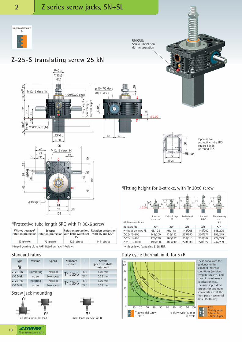
Z-25-S translating screw 25 kN
Z series screw jacks, SN+SL2
*Hinged bearing plate KAR, fitted on face F (below).
Escape/rotation protection
73+stroke
Rotation protectionwith ES and KAR*
149+stroke
Rotation protection,with limit switch set
ES125+stroke
6)Protective tube length SRO with Tr 30x6 screw
Trapezoidal screwTr 30x6
Duty cycle thermal limit, for S+RThese curves are forguidance understandard industrialconditions (ambienttemperature etc.) andcorrect maintenance(lubrication etc.). The max. input drivetorques for optimumservice life are at theright page - technicaldata (1500 rpm)
% duty cycle/10 min at 20°C
Type
Z-25-SNZ-25-SLZ-25-RNZ-25-RL
Speed
Normal
Low speed
Normal
Low speed
i
6:1
24:1
6:1
24:1
Stroke per drive shaft
rotation5)
1.00 mm
0.25 mm
1.00 mm
0.25 mm
Version
Translating
screw
Rotating
screw
Standardscrew2)
Tr 30x6
Tr 30x6
Bellows FB X/Y X/Y X/Y X/Y X/Ywithout bellows FB 68/125 91/148 148/205 145/202 148/205Z-25-FB-300 143/200 135/192 223/280 220/277 192/249Z-25-FB-700 173/230 165/222 253/310 250/307 222/279Z-25-FB-1000 193/250 185/242 273/330 270/327 242/299
*with bellows fixing ring Z-25-FBR
Standard ratios
1)Fitting height for 0-stroke, with Tr 30x6 screw
Standard screw end*
Fixing flange BF
Forked endGK*
Rod endKGK*
Pivot bearingendSLK
Without escape/rotation protection
53+stroke
All dimensions in mm
KGT:% duty cycle2 times to4 times higher
Opening for protective tube SRO square 56x56or round Ø 70
UNIQUE:Screw lubricationduring operation
Trapezoidal screwTr
500 rpm
1000 rpm
1500 rpm
1800 rpm
3000 rpm
40H7/2 deep
M8/10 deepM10/13 deep (4x)20H9/20 deep
M10/13 deep (4x)
M10/13 deep (8x)
SRO
Leng
th
Fitt
ing
heig
ht Y
Scre
w le
ngth
Ove
rall
heig
ht
6)
1 )
Full static nominal load max. load: see Section 8
F
Screw jack mounting
F F
19© by ZIMM Austria 2013
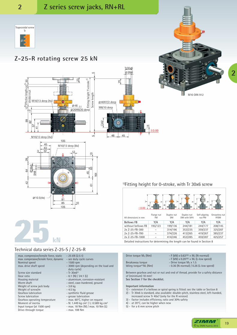
Z-25-R rotating screw 25 kN
Z series screw jacks, RN+RL
max. compressive/tensile force, static - 25 kN (2.5 t)max. compressive/tensile force, dynamic - see duty cycle curvesNominal speed - 1500 rpmmax. drive shaft speed - 3000 rpm (depending on the load and
duty cycle)Screw size standard - Tr 30x62)
Gear ratio - 6:1 (N) / 24:1 (L)Housing material - aluminium, corrosion-resistantWorm shaft - steel, case-hardened, groundWeight of screw jack body - 3.8 kgWeight of screw/m - 4.5 kgGearbox lubrication - synthetic fluid greaseScrew lubrication - grease lubricationGearbox operating temperature - max. 60°C, higher on requestMoment of inertia - N: 1.449 kg cm2 / L: 0.589 kg cm2
Input torque (at 1500 rpm) - max. 18 Nm (N) / max. 10 Nm (L)Drive-through torque - max. 108 Nm
Drive torque MG (Nm) - F (kN) x 0.633)5) + ML (N-normal) - F (kN) x 0.203)5) + ML (L-low speed)Breakaway torque - Drive torque MG x 1.5Idling torque4) ML (Nm) - 0.36 (N-normal) / 0.26 (L-low speed)
Between gearbox and nut or nut and end of thread, provide for a safety distanceof (minimum) 10 mm!See Section 7 for the checklist.
Important information1) - extension if a bellows or spiral spring is fitted: see the table or Section 82) - Tr 30x6 is standard, also available: double-pitch, stainless steel, left-handed,
increased screw Tr 40x7 (only for the R version)3) - factor includes efficiency, ratio and 30% safety4) - at 20°C, can be higher when new5) - for a 6 mm screw pitch
Technical data series Z-25-S / Z-25-R
kN
Bellows FB Y/A Y/A Y/A Y/A Y/Awithout bellows FB 195/123 199/136 244/181 244/177 208/1452x Z-25-FB-300 – 314/196 353/235 359/237 325/2072x Z-25-FB-700 – 374/226 413/265 419/267 385/2372x Z-25-FB-1000 – 414/246 453/285 459/287 425/257
Detailed instructions for determining the length can be found in Section 8
1)Fitting height for 0-stroke, with Tr 30x6 screw
Flange nutFM
Duplex nutDM
Duplex nutDM with SIFA
Self-aligning nut PM
Greaseless nutFFDMAll dimensions in mm
2
2
Trapezoidal screwTr
M10 DIN 912Sc
rew
leng
th
Fitt
ing
heig
ht Y
+str
oke
40H7/2 deep
M8/10 deep
M10/13 deep (4x)
M10/13 deep (8x)
1)
20H9/20 deep
Effe
ctive
leng
th=
stro
ke+n
ut
M10/13 deep (4x)
© by ZIMM Austria 201320
[kN]
0 10 20 30 40 50 60 70 80 90 100
35
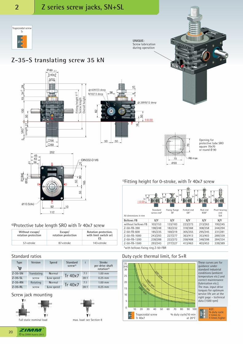
Z-35-S translating screw 35 kN
Z series screw jacks, SN+SL2
Escape/rotation protection
87+stroke
Rotation protection,with limit switch set
ES143+stroke
6)Protective tube length SRO with Tr 40x7 screw
Trapezoidal screwTr 40x7
Duty cycle thermal limit, for S+RThese curves are forguidance understandard industrialconditions (ambienttemperature etc.) andcorrect maintenance(lubrication etc.). The max. input drivetorques for optimumservice life are at theright page - technicaldata (1500 rpm)
% duty cycle/10 min at 20°C
Type
Z-35-SNZ-35-SLZ-35-RNZ-35-RL
Speed
Normal
Low speed
Normal
Low speed
i
7:1
28:1
7:1
28:1
Stroke per drive shaft
rotation5)
1.00 mm
0.25 mm
1.00 mm
0.25 mm
Version
Translating
screw
Rotating
screw
Standardscrew2)
Tr 40x7
Tr 40x7
Bellows FB X/Y X/Y X/Y X/Y X/Ywithout bellows FB 103/153 133/183 223/273 213/263 195/245Z-50-FB-390 198/248 182/232 318/368 308/358 244/294Z-50-FB-600 185/235 169/219 305/355 295/345 231/281Z-50-FB-1000 243/293 227/277 363/413 353/403 289/339Z-50-FB-1200 238/288 222/272 358/408 348/398 284/334Z-50-FB-1500 293/343 277/327 413/463 403/453 339/389
*with bellows fixing ring Z-50-FBR
Standard ratios
1)Fitting height for 0-stroke, with Tr 40x7 screw
Standard screw end*
Fixing flange BF
Forked endGK*
Rod endKGK*
Pivot bearingendSLKAll dimensions in mm
KGT:% duty cycle2 times to4 times higher
Opening for protective tube SRO square 70x70or round Ø 90
UNIQUE:Screw lubricationduring operation
Trapezoidal screwTr
Without escape/rotation protection
57+stroke
30
25
20
15
10
5
500 rpm1000 rpm
1500 rpm1800 rpm
42H7/3 deepM10/13 deep
Scre
w le
ngth
Ove
rall
heig
ht
1)Fi
ttin
g he
ight
Y
1)SR
OLe
ngth6)
28H9/12 deep
Full static nominal load max. load: see Section 8
F
Screw jack mounting
F F
21© by ZIMM Austria 2013
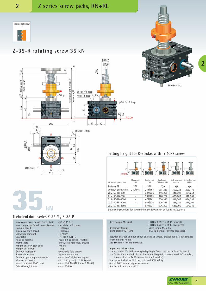
Z-35-R rotating screw 35 kN
Z series screw jacks, RN+RL
max. compressive/tensile force, static - 35 kN (3.5 t)max. compressive/tensile force, dynamic - see duty cycle curvesNominal speed - 1500 rpmmax. drive shaft speed - 1800 rpmScrew size standard - Tr 40x72)
Gear ratio - 7:1 (N) / 28:1 (L)Housing material - GGG-50, corrosion-resistantWorm shaft - steel, case-hardened, groundWeight of screw jack body - 9.5 kgWeight of screw/m - 8 kgGearbox lubrication - synthetic fluid greaseScrew lubrication - grease lubricationGearbox operating temperature - max. 60°C, higher on requestMoment of inertia - N: 2.18 kg cm2 / L: 0.90 kg cm2
Input torque (at 1500 rpm) - max. 19.8 Nm (N) / max. 9 Nm (L)Drive-through torque - max. 130 Nm
Drive torque MG (Nm) - F (kN) x 0.693)5) + ML (N-normal) - F (kN) x 0.233)5) + ML (L-low speed)Breakaway torque - Drive torque MG x 1.5Idling torque4) ML (Nm) - 0.56 (N-normal) / 0.40 (L-low speed)
Between gearbox and nut or nut and end of thread, provide for a safety distanceof (minimum) 10 mm!See Section 7 for the checklist.
Important information1) - extension if a bellows or spiral spring is fitted: see the table or Section 82) - Tr 40x7 is standard, also available: double-pitch, stainless steel, left-handed,
increased screw Tr 55x9 (only for the R version)3) - factor includes efficiency, ratio and 30% safety4) - at 20°C, can be higher when new5) - for a 7 mm screw pitch
Technical data series Z-35-S / Z-35-R
Bellows FB Y/A Y/A Y/A Y/A Y/Awithout bellows FB 240/145 244/163 307/226 303/228 259/1792x Z-50-FB-390 – 387/236 446/295 446/301 404/2542x Z-50-FB-600 – 361/223 420/282 420/288 378/2412x Z-50-FB-1000 – 477/281 536/340 536/346 494/2992x Z-50-FB-1200 – 467/276 526/335 526/341 484/2942x Z-50-FB-1500 – 577/331 636/390 636/396 594/349
Detailed instructions for determining the length can be found in Section 8
1)Fitting height for 0-stroke, with Tr 40x7 screw
Flange nutFM
Duplex nutDM
Duplex nutDM with SIFA
Self-aligningnut PM
Greaseless nutFFDMAll dimensions in mm
kN
2
Trapezoidal screwTr
M10 DIN 912
2
Scre
wle
ngth 42H7/3 deep
M10/13 deep
Effe
ctive
leng
th=
stro
ke+n
ut
Fitt
ing
heig
ht Y
+str
oke1)
1)1)
28H9/12 deep
© by ZIMM Austria 201322
[kN]
10 20 30 40 50 60 70 80 90 100
50
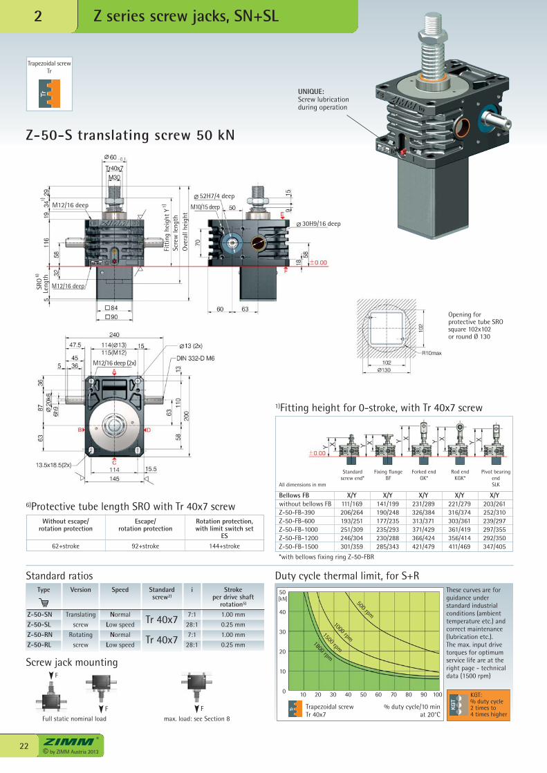
Z-50-S translating screw 50 kN
Z series screw jacks, SN+SL2
Escape/rotation protection
92+stroke
Rotation protection,with limit switch set
ES144+stroke
6)Protective tube length SRO with Tr 40x7 screw
Trapezoidal screwTr 40x7
Duty cycle thermal limit, for S+RThese curves are forguidance understandard industrialconditions (ambienttemperature etc.) andcorrect maintenance(lubrication etc.). The max. input drivetorques for optimumservice life are at theright page - technicaldata (1500 rpm)
% duty cycle/10 min at 20°C
Type
Z-50-SNZ-50-SLZ-50-RNZ-50-RL
Speed
Normal
Low speed
Normal
Low speed
i
7:1
28:1
7:1
28:1
Stroke per drive shaft
rotation5)
1.00 mm
0.25 mm
1.00 mm
0.25 mm
Version
Translating
screw
Rotating
screw
Standardscrew2)
Tr 40x7
Tr 40x7
Bellows FB X/Y X/Y X/Y X/Y X/Ywithout bellows FB 111/169 141/199 231/289 221/279 203/261Z-50-FB-390 206/264 190/248 326/384 316/374 252/310Z-50-FB-600 193/251 177/235 313/371 303/361 239/297Z-50-FB-1000 251/309 235/293 371/429 361/419 297/355Z-50-FB-1200 246/304 230/288 366/424 356/414 292/350Z-50-FB-1500 301/359 285/343 421/479 411/469 347/405
*with bellows fixing ring Z-50-FBR
Standard ratios
1)Fitting height for 0-stroke, with Tr 40x7 screw
Standard screw end*
Fixing flange BF
Forked endGK*
Rod endKGK*
Pivot bearingendSLKAll dimensions in mm
KGT:% duty cycle2 times to4 times higher
Opening for protective tube SRO square 102x102or round Ø 130
UNIQUE:Screw lubricationduring operation
Trapezoidal screwTr
Without escape/rotation protection
62+stroke
500 rpm
1000 rpm1500 rpm1800 rpm
0
40
30
20
10
52H7/4 deep
M10/15 deep
Scre
w le
ngth
Ove
rall
heig
ht
1)Fi
ttin
g he
ight
Y
1)SR
OLe
ngth6)
30H9/16 deep
M12/16 deep (2x)
M12/16 deep
M12/16 deep
Full static nominal load max. load: see Section 8
F
Screw jack mounting
F F
23© by ZIMM Austria 2013
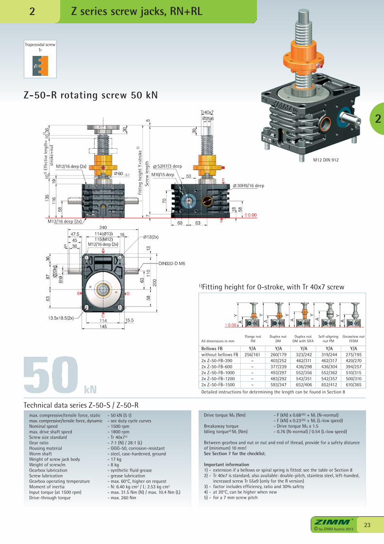
Z-50-R rotating screw 50 kN
Z series screw jacks, RN+RL
max. compressive/tensile force, static - 50 kN (5 t)max. compressive/tensile force, dynamic - see duty cycle curvesNominal speed - 1500 rpmmax. drive shaft speed - 1800 rpmScrew size standard - Tr 40x72)
Gear ratio - 7:1 (N) / 28:1 (L)Housing material - GGG-50, corrosion-resistantWorm shaft - steel, case-hardened, groundWeight of screw jack body - 17 kgWeight of screw/m - 8 kgGearbox lubrication - synthetic fluid greaseScrew lubrication - grease lubricationGearbox operating temperature - max. 60°C, higher on requestMoment of inertia - N: 6.40 kg cm2 / L: 2.53 kg cm2
Input torque (at 1500 rpm) - max. 31.5 Nm (N) / max. 10.4 Nm (L)Drive-through torque - max. 260 Nm
Drive torque MG (Nm) - F (kN) x 0.683)5) + ML (N-normal) - F (kN) x 0.233)5) + ML (L-low speed)Breakaway torque - Drive torque MG x 1.5Idling torque4) ML (Nm) - 0.76 (N-normal) / 0.54 (L-low speed)
Between gearbox and nut or nut and end of thread, provide for a safety distanceof (minimum) 10 mm!See Section 7 for the checklist.
Important information1) - extension if a bellows or spiral spring is fitted: see the table or Section 82) - Tr 40x7 is standard, also available: double-pitch, stainless steel, left-handed,
increased screw Tr 55x9 (only for the R version)3) - factor includes efficiency, ratio and 30% safety4) - at 20°C, can be higher when new5) - for a 7 mm screw pitch
Technical data series Z-50-S / Z-50-R
Bellows FB Y/A Y/A Y/A Y/A Y/Awithout bellows FB 256/161 260/179 323/242 319/244 275/1952x Z-50-FB-390 – 403/252 462/311 462/317 420/2702x Z-50-FB-600 – 377/239 436/298 436/304 394/2572x Z-50-FB-1000 – 493/297 552/356 552/362 510/3152x Z-50-FB-1200 – 483/292 542/351 542/357 500/3102x Z-50-FB-1500 – 593/347 652/406 652/412 610/365
Detailed instructions for determining the length can be found in Section 8
1)Fitting height for 0-stroke, with Tr 40x7 screw
Flange nutFM
Duplex nutDM
Duplex nutDM with SIFA
Self-aligningnut PM
Greaseless nutFFDMAll dimensions in mm
kN
2
Trapezoidal screwTr
M12 DIN 912
2
Scre
w le
ngth 52H7/3 deep
M10/15 deep
Effe
ctiv
e le
ngth
=st
roke
+nut
Fitt
ing
heig
ht Y
+str
oke1)
1)1)
30H9/16 deep
M12/16 deep (2x)
M12/16 deep (2x)
M12/16 deep (2x)

© by ZIMM Austria 201324
[kN]
10 20 30 40 50 60 70 80 90 100
50
Z-50/Tr50-S translating screw 50 kN
Z series screw jacks, SN+SL2
Escape/rotation protection
92+stroke
Rotation protection,with limit switch set
ES144+stroke
6)Protective tube length SRO with Tr 50x8 screw
Trapezoidal screwTr 50x8
Duty cycle thermal limit, for SThese curves are forguidance understandard industrialconditions (ambienttemperature etc.) andcorrect maintenance(lubrication etc.). The max. input drivetorques for optimumservice life are at theright page - technicaldata (1500 rpm)
% duty cycle/10 min at 20°C
Type
Z-50/Tr50-SNZ-50/Tr50-SL
Speed
Normal
Low speed
i
7:1
28:1
Stroke per drive shaft
rotation5)
1.143 mm
0.286 mm
Version
Translating
screw
Standardscrew2)
Tr 50x8
Bellows FB X/Y X/Y X/Y X/Y X/Ywithout bellows FB 115/173 165/223 259/317 257/315 223/281Z-100-FB-285 198/256 200/258 342/400 340/398 258/316Z-100-FB-600 195/253 197/255 339/397 337/395 255/313Z-100-FB-1000 253/311 255/313 397/455 395/453 313/371Z-100-FB-1500 303/361 305/363 447/505 445/503 363/421
*with bellows fixing ring Z-100-FBR
Standard ratios
1)Fitting height for 0-stroke, with Tr 50x8 screw
Standard screw end*
Fixing flange BF
Forked endGK*
Rod endKGK*
Pivot bearingendSLKAll dimensions in mm
KGT:% duty cycle2 times to4 times higher
Opening for protective tube SRO square 102x102or round Ø 130
UNIQUE:Screw lubricationduring operation
Trapezoidal screwTr
500 rpm1000 rpm
1500 rpm
1800 rpm
Without escape/rotation protection
62+stroke
0
40
30
20
10
52H7/4 deep
M10/15 deep
Scre
w le
ngth
Ove
rall
heig
ht
Fitt
ing
heig
ht Y
1)SR
OLe
ngth6)
30H9/16 deep
For Z-50/Tr50, use screw-relatedaccessories from the Z-100.
Full static nominal load max. load: see Section 8
F
Screw jack mounting
F F
1)
25© by ZIMM Austria 2013
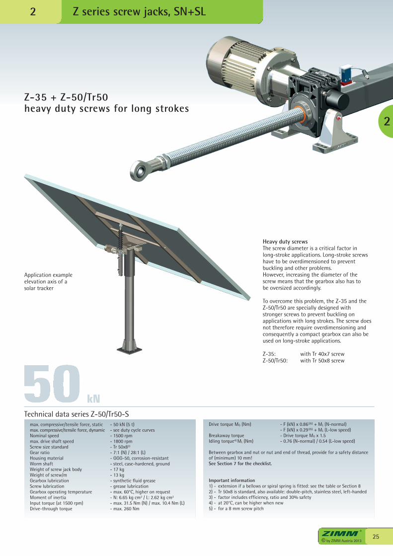
Z-35 + Z-50/Tr50 heavy duty screws for long strokes
Z series screw jacks, SN+SL
max. compressive/tensile force, static - 50 kN (5 t)max. compressive/tensile force, dynamic - see duty cycle curvesNominal speed - 1500 rpmmax. drive shaft speed - 1800 rpmScrew size standard - Tr 50x82)
Gear ratio - 7:1 (N) / 28:1 (L)Housing material - GGG-50, corrosion-resistantWorm shaft - steel, case-hardened, groundWeight of screw jack body - 17 kgWeight of screw/m - 13 kgGearbox lubrication - synthetic fluid greaseScrew lubrication - grease lubricationGearbox operating temperature - max. 60°C, higher on requestMoment of inertia - N: 6.65 kg cm2 / L: 2.62 kg cm2
Input torque (at 1500 rpm) - max. 31.5 Nm (N) / max. 10.4 Nm (L)Drive-through torque - max. 260 Nm
Drive torque MG (Nm) - F (kN) x 0.863)5) + ML (N-normal) - F (kN) x 0.293)5) + ML (L-low speed)Breakaway torque - Drive torque MG x 1.5Idling torque4) ML (Nm) - 0.76 (N-normal) / 0.54 (L-low speed)
Between gearbox and nut or nut and end of thread, provide for a safety distanceof (minimum) 10 mm!See Section 7 for the checklist.
Important information1) - extension if a bellows or spiral spring is fitted: see the table or Section 82) - Tr 50x8 is standard, also available: double-pitch, stainless steel, left-handed3) - factor includes efficiency, ratio and 30% safety4) - at 20°C, can be higher when new5) - for a 8 mm screw pitch
Technical data series Z-50/Tr50-S
kN
2
2
Heavy duty screwsThe screw diameter is a critical factor in long-stroke applications. Long-stroke screwshave to be overdimensioned to preventbuckling and other problems. However, increasing the diameter of the screw means that the gearbox also has to be oversized accordingly.
To overcome this problem, the Z-35 and the Z-50/Tr50 are specially designed with stronger screws to prevent buckling onapplications with long strokes. The screw doesnot therefore require overdimensioning andconsequently a compact gearbox can also beused on long-stroke applications.
Z-35: with Tr 40x7 screwZ-50/Tr50: with Tr 50x8 screw
Application exampleelevation axis of asolar tracker
© by ZIMM Austria 201326
[kN]
10 20 30 40 50 60 70 80 90 100
100
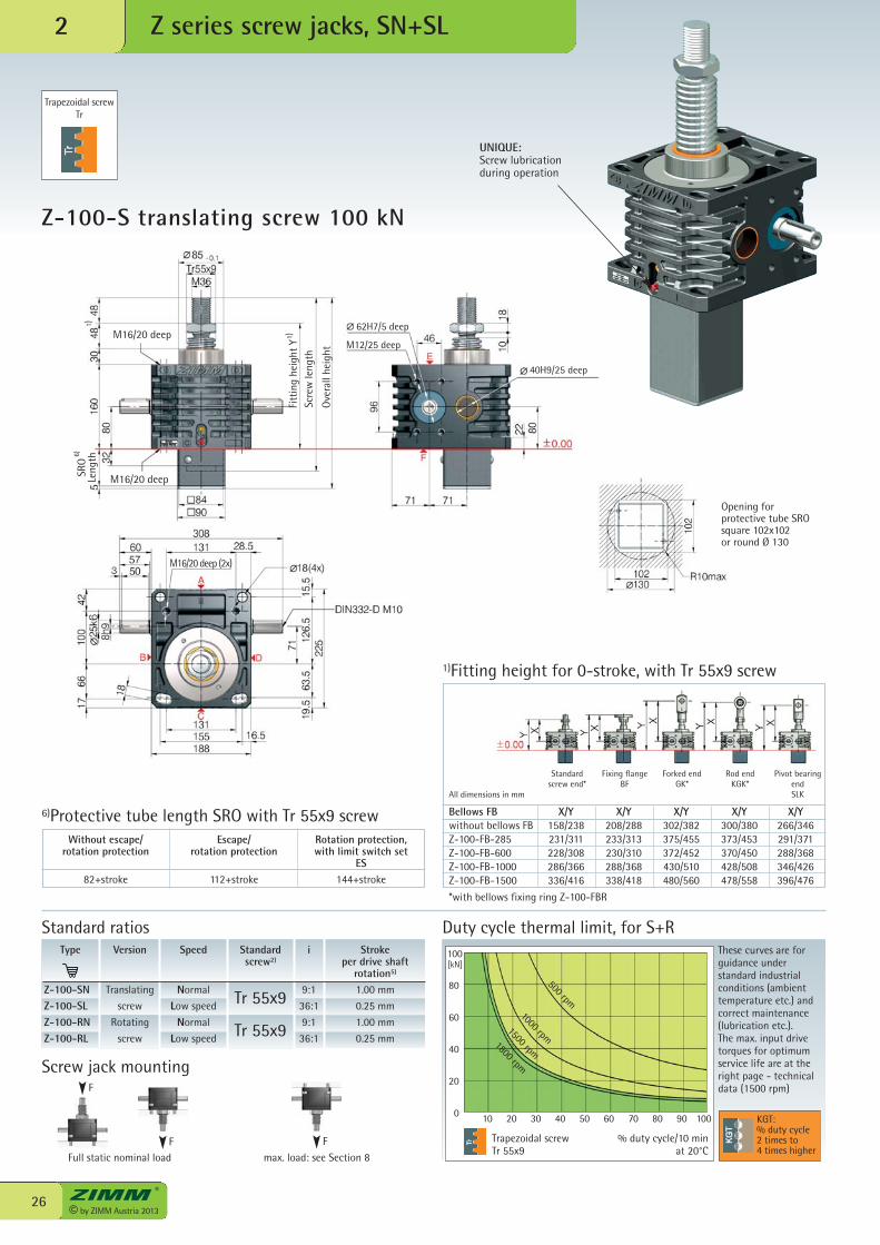
Z-100-S translating screw 100 kN
Z series screw jacks, SN+SL2
Rotation protection,with limit switch set
ES144+stroke
6)Protective tube length SRO with Tr 55x9 screw
Trapezoidal screwTr 55x9
Duty cycle thermal limit, for S+RThese curves are forguidance understandard industrialconditions (ambienttemperature etc.) andcorrect maintenance(lubrication etc.). The max. input drivetorques for optimumservice life are at theright page - technicaldata (1500 rpm)
% duty cycle/10 min at 20°C
Type
Z-100-SNZ-100-SLZ-100-RNZ-100-RL
Speed
Normal
Low speed
Normal
Low speed
i
9:1
36:1
9:1
36:1
Stroke per drive shaft
rotation5)
1.00 mm
0.25 mm
1.00 mm
0.25 mm
Version
Translating
screw
Rotating
screw
Standardscrew2)
Tr 55x9
Tr 55x9
Bellows FB X/Y X/Y X/Y X/Y X/Ywithout bellows FB 158/238 208/288 302/382 300/380 266/346Z-100-FB-285 231/311 233/313 375/455 373/453 291/371Z-100-FB-600 228/308 230/310 372/452 370/450 288/368Z-100-FB-1000 286/366 288/368 430/510 428/508 346/426Z-100-FB-1500 336/416 338/418 480/560 478/558 396/476
*with bellows fixing ring Z-100-FBR
Standard ratios
1)Fitting height for 0-stroke, with Tr 55x9 screw
Standard screw end*
Fixing flange BF
Forked endGK*
Rod endKGK*
Pivot bearingendSLKAll dimensions in mm
KGT:% duty cycle2 times to4 times higher
Opening for protective tube SRO square 102x102or round Ø 130
UNIQUE:Screw lubricationduring operation
Without escape/rotation protection
82+stroke
500 rpm1000 rpm
1500 rpm1800 rpm
Trapezoidal screwTr
Escape/rotation protection
112+stroke
0
80
60
40
20
62H7/5 deep
M12/25 deep
Scre
w le
ngth
Ove
rall
heig
ht
1)Fi
ttin
g he
ight
Y
1)SR
OLe
ngth6)
M16/20 deep (2x)
M16/20 deep
M16/20 deep
40H9/25 deep
Full static nominal load max. load: see Section 8
F
Screw jack mounting
F F
27© by ZIMM Austria 2013
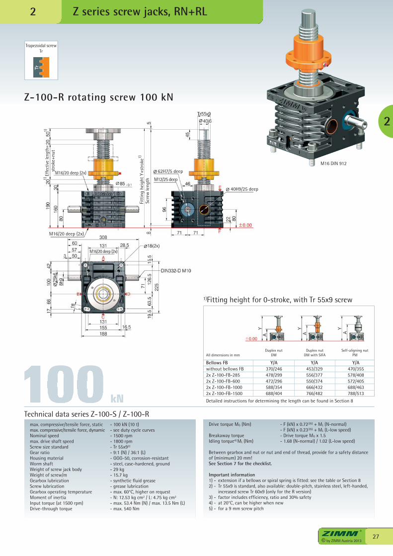
Z-100-R rotating screw 100 kN
Z series screw jacks, RN+RL
max. compressive/tensile force, static - 100 kN (10 t)max. compressive/tensile force, dynamic - see duty cycle curvesNominal speed - 1500 rpmmax. drive shaft speed - 1800 rpmScrew size standard - Tr 55x92)
Gear ratio - 9:1 (N) / 36:1 (L)Housing material - GGG-50, corrosion-resistantWorm shaft - steel, case-hardened, groundWeight of screw jack body - 29 kgWeight of screw/m - 15.7 kgGearbox lubrication - synthetic fluid greaseScrew lubrication - grease lubricationGearbox operating temperature - max. 60°C, higher on requestMoment of inertia - N: 12.53 kg cm2 / L: 4.75 kg cm2
Input torque (at 1500 rpm) - max. 53.4 Nm (N) / max. 13.5 Nm (L)Drive-through torque - max. 540 Nm
Drive torque MG (Nm) - F (kN) x 0.723)5) + ML (N-normal) - F (kN) x 0.233)5) + ML (L-low speed)Breakaway torque - Drive torque MG x 1.5Idling torque4) ML (Nm) - 1.68 (N-normal) / 1.02 (L-low speed)
Between gearbox and nut or nut and end of thread, provide for a safety distanceof (minimum) 20 mm!See Section 7 for the checklist.
Important information1) - extension if a bellows or spiral spring is fitted: see the table or Section 82) - Tr 55x9 is standard, also available: double-pitch, stainless steel, left-handed,
increased screw Tr 60x9 (only for the R version)3) - factor includes efficiency, ratio and 30% safety4) - at 20°C, can be higher when new5) - for a 9 mm screw pitch
Technical data series Z-100-S / Z-100-R
Bellows FB Y/A Y/A Y/Awithout bellows FB 370/246 453/329 470/3552x Z-100-FB-285 478/299 556/377 578/4082x Z-100-FB-600 472/296 550/374 572/4052x Z-100-FB-1000 588/354 666/432 688/4632x Z-100-FB-1500 688/404 766/482 788/513
Detailed instructions for determining the length can be found in Section 8
1)Fitting height for 0-stroke, with Tr 55x9 screw
Duplex nutDM
Duplex nutDM with SIFA
Self-aligning nutPMAll dimensions in mm
kN
2
Trapezoidal screwTr
M16 DIN 912
2
62H7/5 deep
M12/25 deep
Effe
ctiv
e le
ngth
=st
roke
+nut
Fitt
ing
heig
ht Y
+str
oke1)
1)1)
40H9/25 deep
M16/20 deep (2x)
M16/20 deep (2x)
M16/20 deep (2x)
Scre
w le
ngth
© by ZIMM Austria 201328
[kN]
10 20 30 40 50 60 70 80 90 100
150
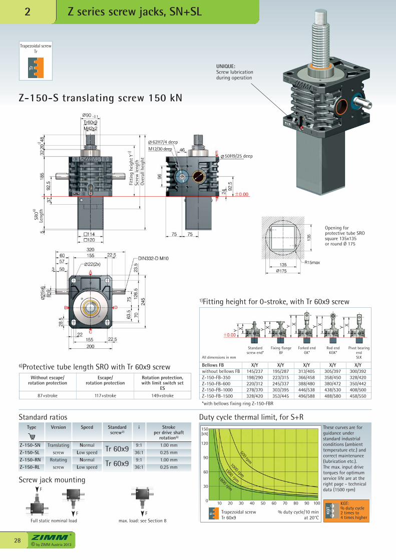
Z-150-S translating screw 150 kN
Z series screw jacks, SN+SL2
Escape/rotation protection
117+stroke
Rotation protection,with limit switch set
ES149+stroke
6)Protective tube length SRO with Tr 60x9 screw
Trapezoidal screwTr 60x9
Duty cycle thermal limit, for S+RThese curves are forguidance understandard industrialconditions (ambienttemperature etc.) andcorrect maintenance(lubrication etc.). The max. input drivetorques for optimumservice life are at theright page - technicaldata (1500 rpm)
% duty cycle/10 min at 20°C
Type
Z-150-SNZ-150-SLZ-150-RNZ-150-RL
Speed
Normal
Low speed
Normal
Low speed
i
9:1
36:1
9:1
36:1
Stroke per drive shaft
rotation5)
1.00 mm
0.25 mm
1.00 mm
0.25 mm
Version
Translating
screw
Rotating
screw
Standardscrew2)
Tr 60x9
Tr 60x9
Standard ratios
KGT:% duty cycle2 times to4 times higher
Opening for protective tube SRO square 135x135or round Ø 175
UNIQUE:Screw lubricationduring operation
Trapezoidal screwTr
500 rpm
1000 rpm1500 rpm1800 rpm
Bellows FB X/Y X/Y X/Y X/Y X/Ywithout bellows FB 145/237 195/287 313/405 305/397 300/392Z-150-FB-350 198/290 223/315 366/458 358/450 328/420Z-150-FB-600 220/312 245/337 388/480 380/472 350/442Z-150-FB-1000 278/370 303/395 446/538 438/530 408/500Z-150-FB-1500 328/420 353/445 496/588 488/580 458/550
*with bellows fixing ring Z-150-FBR
1)Fitting height for 0-stroke, with Tr 60x9 screw
Standard screw end*
Fixing flange BF
Forked endGK*
Rod endKGK*
Pivot bearingendSLKAll dimensions in mm
Without escape/rotation protection
87+stroke
0
120
90
60
30
62H7/4 deepM12/30 deep
Scre
w le
ngth
Ove
rall
heig
ht
1)Fi
ttin
g he
ight
Y
1)SR
OLe
ngth6)
50H9/25 deep
Full static nominal load max. load: see Section 8
F
Screw jack mounting
F F
29© by ZIMM Austria 2013
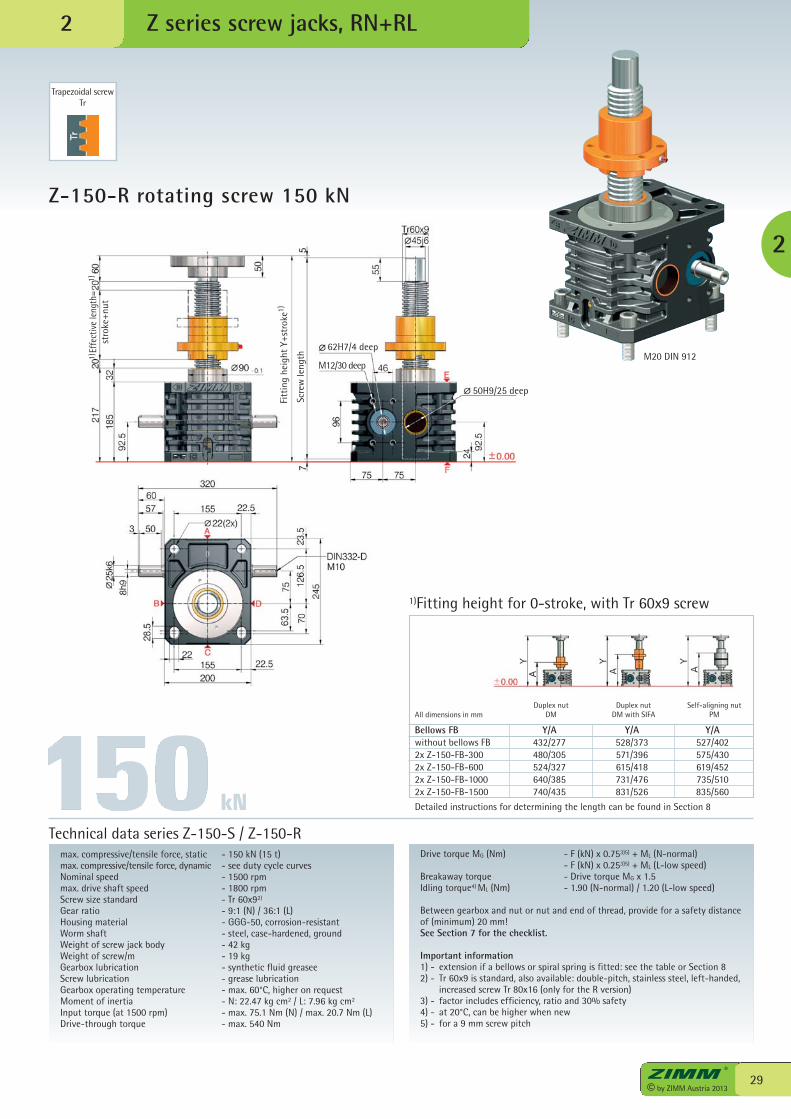
Z-150-R rotating screw 150 kN
Z series screw jacks, RN+RL
max. compressive/tensile force, static - 150 kN (15 t)max. compressive/tensile force, dynamic - see duty cycle curvesNominal speed - 1500 rpmmax. drive shaft speed - 1800 rpmScrew size standard - Tr 60x92)
Gear ratio - 9:1 (N) / 36:1 (L)Housing material - GGG-50, corrosion-resistantWorm shaft - steel, case-hardened, groundWeight of screw jack body - 42 kgWeight of screw/m - 19 kgGearbox lubrication - synthetic fluid greaseeScrew lubrication - grease lubricationGearbox operating temperature - max. 60°C, higher on requestMoment of inertia - N: 22.47 kg cm2 / L: 7.96 kg cm2
Input torque (at 1500 rpm) - max. 75.1 Nm (N) / max. 20.7 Nm (L)Drive-through torque - max. 540 Nm
Drive torque MG (Nm) - F (kN) x 0.753)5) + ML (N-normal) - F (kN) x 0.253)5) + ML (L-low speed)Breakaway torque - Drive torque MG x 1.5Idling torque4) ML (Nm) - 1.90 (N-normal) / 1.20 (L-low speed)
Between gearbox and nut or nut and end of thread, provide for a safety distanceof (minimum) 20 mm!See Section 7 for the checklist.
Important information1) - extension if a bellows or spiral spring is fitted: see the table or Section 82) - Tr 60x9 is standard, also available: double-pitch, stainless steel, left-handed,
increased screw Tr 80x16 (only for the R version)3) - factor includes efficiency, ratio and 30% safety4) - at 20°C, can be higher when new5) - for a 9 mm screw pitch
Technical data series Z-150-S / Z-150-R
kN
2
Trapezoidal screwTr
M20 DIN 912
2
Bellows FB Y/A Y/A Y/Awithout bellows FB 432/277 528/373 527/4022x Z-150-FB-300 480/305 571/396 575/4302x Z-150-FB-600 524/327 615/418 619/4522x Z-150-FB-1000 640/385 731/476 735/5102x Z-150-FB-1500 740/435 831/526 835/560
Detailed instructions for determining the length can be found in Section 8
1)Fitting height for 0-stroke, with Tr 60x9 screw
Duplex nutDM
Duplex nutDM with SIFA
Self-aligning nutPMAll dimensions in mm
Scre
w le
ngth
62H7/4 deep
M12/30 deep
Effe
ctiv
e le
ngth
=st
roke
+nut
Fitt
ing
heig
ht Y
+str
oke1)
1)1)
50H9/25 deep
© by ZIMM Austria 201330
[kN]
0 10 20 30 40 50 60 70 80 90 100
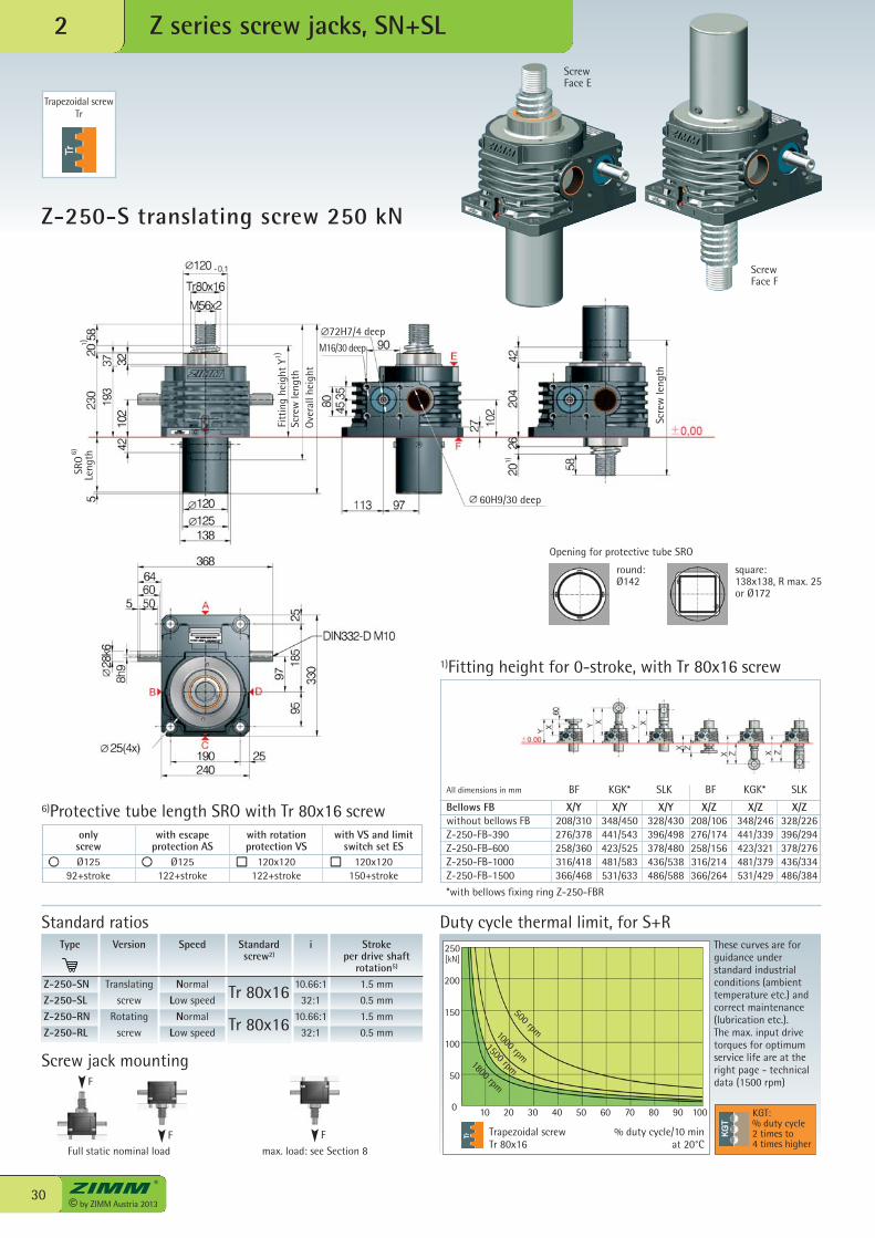
250
2
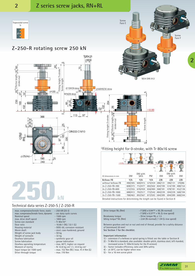
Trapezoidal screwTr 80x16
Duty cycle thermal limit, for S+RThese curves are forguidance understandard industrialconditions (ambienttemperature etc.) andcorrect maintenance(lubrication etc.). The max. input drivetorques for optimumservice life are at theright page - technicaldata (1500 rpm)
% duty cycle/10 min at 20°C
Type
Z-250-SNZ-250-SLZ-250-RNZ-250-RL
Speed
Normal
Low speed
Normal
Low speed
i
10.66:1
32:1
10.66:1
32:1
Stroke per drive shaft
rotation5)
1.5 mm
0.5 mm
1.5 mm
0.5 mm
Version
Translating
screw
Rotating
screw
Standardscrew2)
Tr 80x16
Tr 80x16
Standard ratios
KGT:% duty cycle2 times to4 times higher
Trapezoidal screwTr
500 rpm1000 rpm1500 rpm1800 rpm
ScrewFace E
ScrewFace F
Z-250-S translating screw 250 kN
Z series screw jacks, SN+SL
1)Fitting height for 0-stroke, with Tr 80x16 screw
200
150
100
50
72H7/4 deep
M16/30 deep
60H9/30 deep
SRO
Leng
th
Fitt
ing
heig
ht Y
Scre
w le
ngth
Ove
rall
heig
ht
6)
1)
1)
Scre
w le
ngth
Bellows FB X/Y X/Y X/Y X/Z X/Z X/Zwithout bellows FB 208/310 348/450 328/430 208/106 348/246 328/226Z-250-FB-390 276/378 441/543 396/498 276/174 441/339 396/294Z-250-FB-600 258/360 423/525 378/480 258/156 423/321 378/276Z-250-FB-1000 316/418 481/583 436/538 316/214 481/379 436/334Z-250-FB-1500 366/468 531/633 486/588 366/264 531/429 486/384
*with bellows fixing ring Z-250-FBR
BF KGK* SLKAll dimensions in mm BF KGK* SLK
Opening for protective tube SRO
round:Ø142
square:138x138, R max. 25 or Ø172
with escapeprotection AS
Ø125122+stroke
with VS and limitswitch set ES
120x120150+stroke
with rotationprotection VS
120x120122+stroke
6)Protective tube length SRO with Tr 80x16 screwonly
screwØ125
92+stroke
1)
Full static nominal load max. load: see Section 8
F
Screw jack mounting
F F
31© by ZIMM Austria 2013
Z-250-R rotating screw 250 kN
Z series screw jacks, RN+RL
max. compressive/tensile force, static - 250 kN (25 t)max. compressive/tensile force, dynamic - see duty cycle curvesNominal speed - 1500 rpmmax. drive shaft speed - 1800 rpmScrew size standard - Tr 80x162)
Gear ratio - 10.66:1 (N) / 32:1 (L)Housing material - GGG-50, corrosion-resistantWorm shaft - steel, case-hardened, groundWeight of screw jack body - 59 kgWeight of screw/m - 32 kgGearbox lubrication - synthetic gear oilScrew lubrication - grease lubricationGearbox operating temperature - max. 60°C, higher on requestMoment of inertia - N: 53.8 kg cm2 / L: 22.0 kg cm2
Input torque (at 1500 rpm) - max. 152 Nm (N) / max. 41.4 Nm (L)Drive-through torque - max. 770 Nm
Drive torque MG (Nm) - F (kN) x 0.943)5) + ML (N-normal) - F (kN) x 0.373)5) + ML (L-low speed)Breakaway torque - Drive torque MG x 1.5Idling torque4) ML (Nm) - 2.64 (N-normal) / 1.94 (L-low speed)
Between gearbox and nut or nut and end of thread, provide for a safety distanceof (minimum) 20 mm!See Section 7 for the checklist.
Important information1) - extension if a bellows or spiral spring is fitted: see the table or Section 82) - Tr 80x16 is standard, also available: double-pitch, stainless steel, left-handed,
increased screw Tr 100x16 (only for the R version)3) - factor includes efficiency, ratio and 30% safety4) - at 20°C, can be higher when new5) - for a 16 mm screw pitch
Technical data series Z-250-S / Z-250-R
kN
Trapezoidal screwTr
2
M24 DIN 912
ScrewFace F
ScrewFace E
2
1)Fitting height for 0-stroke, with Tr 80x16 screw
Scre
w le
ngth
Fitt
ing
heig
ht Y
+str
oke
Effe
ctiv
e le
ngth
=st
roke
+nut
72H7/4 deep
M16/30 deep
60H9/30 deep
1)
1)1)
1)1)
Scre
w le
ngth
Effe
ctiv
e le
ngth
=st
roke
+nut
Fitt
ing
heig
ht Z
+str
oke
Bellows FB Y/A Y/A Y/A Z/B Z/B Z/Bwithout bellows FB 490/305 600/415 574/434 286/131 396/131 370/862x Z-250-FB-390 608/373 712/477 692/502 404/199 514/199 488/1542x Z-250-FB-600 572/355 676/459 656/484 368/181 478/181 452/1362x Z-250-FB-1000 688/413 792/517 772/542 484/239 594/239 568/1942x Z-250-FB-1500 788/463 892/567 872/592 584/289 694/289 668/244
Detailed instructions for determining the length can be found in Section 8
DMDM with
SIFA PMAll dimensions in mm DMDM with
SIFA DM
© by ZIMM Austria 201332
[kN]
0 10 20 30 40 50 60 70 80 90 100
350
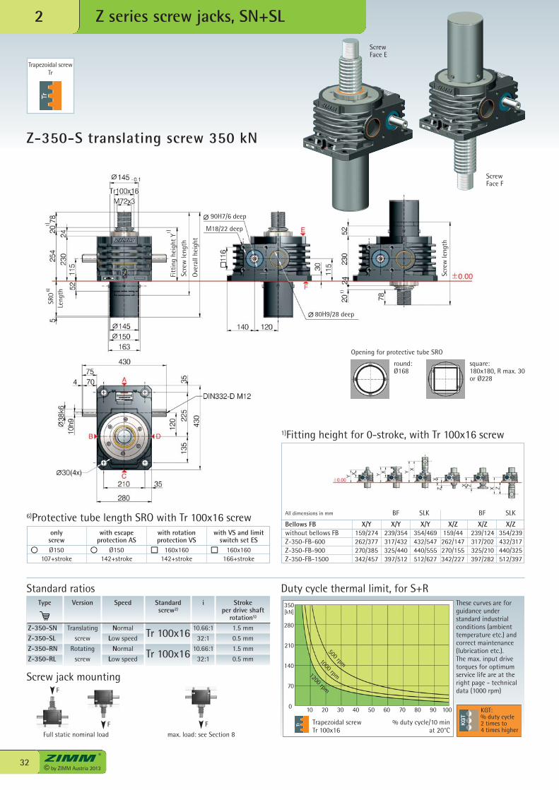
Z-350-S translating screw 350 kN
2
Trapezoidal screwTr 100x16
Duty cycle thermal limit, for S+RThese curves are forguidance understandard industrialconditions (ambienttemperature etc.) andcorrect maintenance(lubrication etc.). The max. input drivetorques for optimumservice life are at theright page - technicaldata (1000 rpm)
% duty cycle/10 min at 20°C
KGT:% duty cycle2 times to4 times higher
Trapezoidal screwTr
500 rpm1000 rpm1200 rpm
ScrewFace E
ScrewFace F
Z series screw jacks, SN+SL
1)Fitting height for 0-stroke, with Tr 100x16 screw
280
210
140
70
Type
Z-350-SNZ-350-SLZ-350-RNZ-350-RL
Speed
Normal
Low speed
Normal
Low speed
i
10.66:1
32:1
10.66:1
32:1
Stroke per drive shaft
rotation5)
1.5 mm
0.5 mm
1.5 mm
0.5 mm
Version
Translating
screw
Rotating
screw
Standardscrew2)
Tr 100x16
Tr 100x16
Standard ratios
90H7/6 deep
M18/22 deep
80H9/28 deep
SRO
Leng
th
Fitt
ing
heig
ht Y
Scre
w le
ngth
Ove
rall
heig
ht
6)
1)
1)
Scre
wle
ngth
Bellows FB X/Y X/Y X/Y X/Z X/Z X/Zwithout bellows FB 159/274 239/354 354/469 159/44 239/124 354/239Z-350-FB-600 262/377 317/432 432/547 262/147 317/202 432/317Z-350-FB-900 270/385 325/440 440/555 270/155 325/210 440/325Z-350-FB-1500 342/457 397/512 512/627 342/227 397/282 512/397
BF SLKAll dimensions in mm BF SLK
Opening for protective tube SRO
round:Ø168
square:180x180, R max. 30 or Ø228
with escapeprotection AS
Ø150142+stroke
with VS and limitswitch set ES
160x160166+stroke
with rotationprotection VS
160x160142+stroke
6)Protective tube length SRO with Tr 100x16 screwonly
screwØ150
107+stroke
1)
Full static nominal load max. load: see Section 8
F
Screw jack mounting
F F
33© by ZIMM Austria 2013
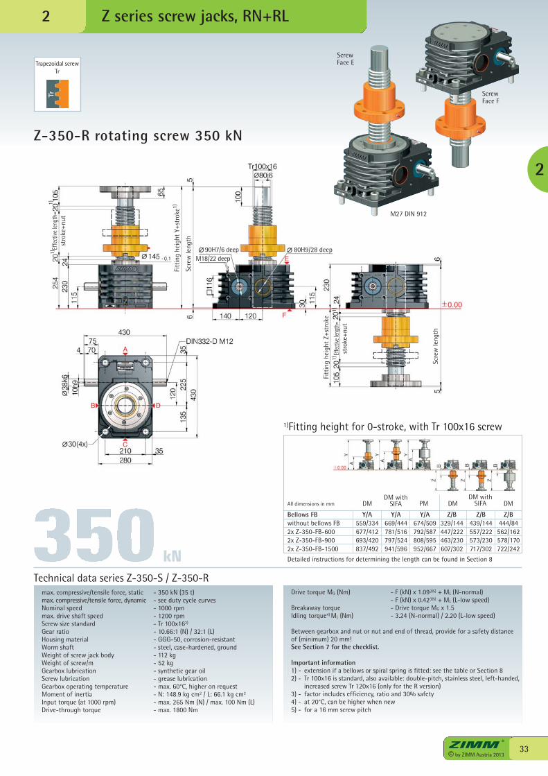
Z-350-R rotating screw 350 kN
Z series screw jacks, RN+RL
max. compressive/tensile force, static - 350 kN (35 t)max. compressive/tensile force, dynamic - see duty cycle curvesNominal speed - 1000 rpmmax. drive shaft speed - 1200 rpmScrew size standard - Tr 100x162)
Gear ratio - 10.66:1 (N) / 32:1 (L)Housing material - GGG-50, corrosion-resistantWorm shaft - steel, case-hardened, groundWeight of screw jack body - 112 kgWeight of screw/m - 52 kgGearbox lubrication - synthetic gear oilScrew lubrication - grease lubricationGearbox operating temperature - max. 60°C, higher on requestMoment of inertia - N: 148.9 kg cm2 / L: 66.1 kg cm2
Input torque (at 1000 rpm) - max. 265 Nm (N) / max. 100 Nm (L)Drive-through torque - max. 1800 Nm
Drive torque MG (Nm) - F (kN) x 1.093)5) + ML (N-normal) - F (kN) x 0.423)5) + ML (L-low speed)Breakaway torque - Drive torque MG x 1.5Idling torque4) ML (Nm) - 3.24 (N-normal) / 2.20 (L-low speed)
Between gearbox and nut or nut and end of thread, provide for a safety distanceof (minimum) 20 mm!See Section 7 for the checklist.
Important information1) - extension if a bellows or spiral spring is fitted: see the table or Section 82) - Tr 100x16 is standard, also available: double-pitch, stainless steel, left-handed,
increased screw Tr 120x16 (only for the R version)3) - factor includes efficiency, ratio and 30% safety4) - at 20°C, can be higher when new5) - for a 16 mm screw pitch
Technical data series Z-350-S / Z-350-R
kN
2
Trapezoidal screwTr
2
M27 DIN 912
ScrewFace E
ScrewFace F
1)Fitting height for 0-stroke, with Tr 100x16 screw
Scre
w le
ngth
Fitt
ing
heig
ht Y
+str
oke
Effe
ctive
leng
th=
stro
ke+n
ut
90H7/6 deepM18/22 deep
80H9/28 deep
1)
1)1)
Scre
wle
ngth
Effec
tive l
engt
h=st
roke
+nut
Fitt
ing
heig
ht Z
+str
oke
1)1)
Bellows FB Y/A Y/A Y/A Z/B Z/B Z/Bwithout bellows FB 559/334 669/444 674/509 329/144 439/144 444/842x Z-350-FB-600 677/412 781/516 792/587 447/222 557/222 562/1622x Z-350-FB-900 693/420 797/524 808/595 463/230 573/230 578/1702x Z-350-FB-1500 837/492 941/596 952/667 607/302 717/302 722/242
Detailed instructions for determining the length can be found in Section 8
DMDM with
SIFA PMAll dimensions in mm DMDM with
SIFA DM
© by ZIMM Austria 201334
[kN]
10 20 30 40 50 60 70 80 90 100
500
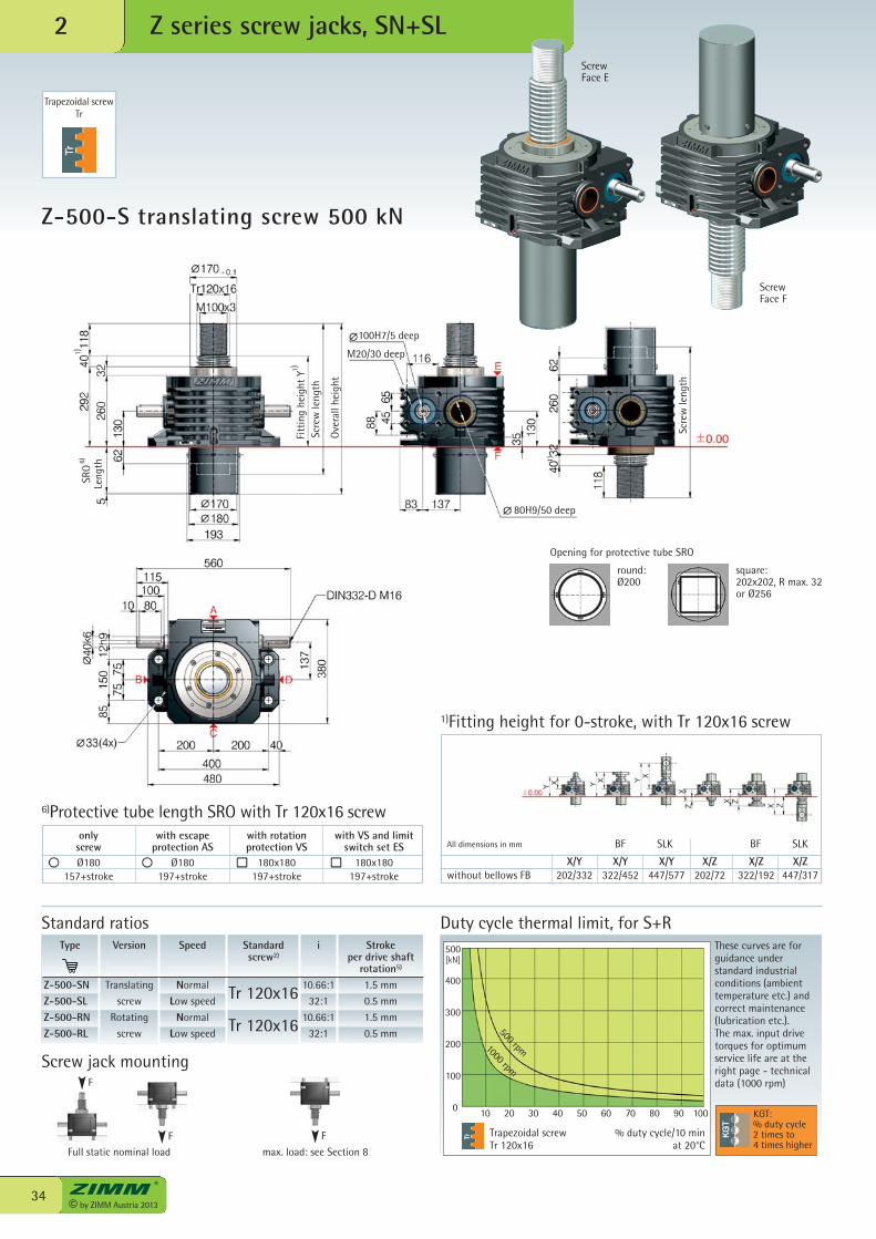
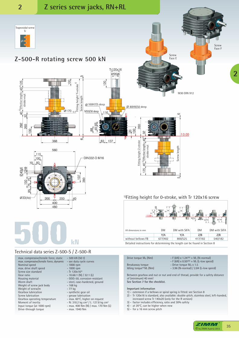
Z-500-S translating screw 500 kN
2
Trapezoidal screwTr 120x16
Duty cycle thermal limit, for S+RThese curves are forguidance understandard industrialconditions (ambienttemperature etc.) andcorrect maintenance(lubrication etc.). The max. input drivetorques for optimumservice life are at theright page - technicaldata (1000 rpm)
% duty cycle/10 min at 20°C
KGT:% duty cycle2 times to4 times higher
Trapezoidal screwTr
500 rpm1000 rpm
ScrewFace E
ScrewFace F
Z series screw jacks, SN+SL
1)Fitting height for 0-stroke, with Tr 120x16 screw
Type
Z-500-SNZ-500-SLZ-500-RNZ-500-RL
Speed
Normal
Low speed
Normal
Low speed
i
10.66:1
32:1
10.66:1
32:1
Stroke per drive shaft
rotation5)
1.5 mm
0.5 mm
1.5 mm
0.5 mm
Version
Translating
screw
Rotating
screw
Standardscrew2)
Tr 120x16
Tr 120x16
Standard ratios
400
300
200
100
0
100H7/5 deep
M20/30 deep
80H9/50 deep
SRO
Leng
th
Fitt
ing
heig
ht Y
Scre
wle
ngth
Ove
rall
heig
ht
6)
1 )
1)
Scre
wle
ngth
X/Y X/Y X/Y X/Z X/Z X/Zwithout bellows FB 202/332 322/452 447/577 202/72 322/192 447/317
BF SLKAll dimensions in mm BF SLK
Opening for protective tube SRO
round:Ø200
square:202x202, R max. 32 or Ø256
with escapeprotection AS
Ø180197+stroke
with VS and limitswitch set ES
180x180197+stroke
with rotationprotection VS
180x180197+stroke
6)Protective tube length SRO with Tr 120x16 screwonly
screwØ180
157+stroke
1)
Full static nominal load max. load: see Section 8
F
Screw jack mounting
F F
35© by ZIMM Austria 2013
Z-500-R rotating screw 500 kN
Z series screw jacks, RN+RL
max. compressive/tensile force, static - 500 kN (50 t)max. compressive/tensile force, dynamic - see duty cycle curvesNominal speed - 1000 rpmmax. drive shaft speed - 1000 rpmScrew size standard - Tr 120x162)
Gear ratio - 10.66:1 (N) / 32:1 (L)Housing material - GGG-50, corrosion-resistantWorm shaft - steel, case-hardened, groundWeight of screw jack body - 168 kgWeight of screw/m - 77 kgGearbox lubrication - synthetic gear oilScrew lubrication - grease lubricationGearbox operating temperature - max. 60°C, higher on requestMoment of inertia - N: 310.2 kg cm2 / L: 127.8 kg cm2
Input torque (at 1000 rpm) - max. 408 Nm (N) / max. 170 Nm (L)Drive-through torque - max. 1940 Nm
Drive torque MG (Nm) - F (kN) x 1.243)5) + ML (N-normal) - F (kN) x 0.503)5) + ML (L-low speed)Breakaway torque - Drive torque MG x 1.5Idling torque4) ML (Nm) - 3.96 (N-normal) / 2.84 (L-low speed)
Between gearbox and nut or nut and end of thread, provide for a safety distanceof (minimum) 40 mm!See Section 7 for the checklist.
Important information1) - extension if a bellows or spiral spring is fitted: see Section 82) - Tr 120x16 is standard, also available: double-pitch, stainless steel, left-handed,
increased screw Tr 140x20 (only for the R version)3) - factor includes efficiency, ratio and 30% safety4) - at 20°C, can be higher when new5) - for a 16 mm screw pitch
Technical data series Z-500-S / Z-500-R
kN
Trapezoidal screwTr
2
M30 DIN 912
ScrewFace E
ScrewFace F
2
1)Fitting height for 0-stroke, with Tr 120x16 screw
Scre
wle
ngth
100H7/5 deep
M20/30 deep
Effe
ctiv
e le
ngth
=st
roke
+nut
Fitt
ing
heig
ht Y
+str
oke
Fitt
ing
heig
ht Z
+str
oke
1)
1)1)
Scre
w le
ngth
Effe
ctiv
e le
ngth
=st
roke
+nut
80H9/50 deep
1)1)
Y/A Y/A Z/B Z/Bwithout bellows FB 677/402 800/525 417/182 540/182
Detailed instructions for determining the length can be found in Section 8
DM DM with SIFA DM DM with SIFAAll dimensions in mm
© by ZIMM Austria 201336
[kN]
0 10 20 30 40 50 60 70 80 90 100
750
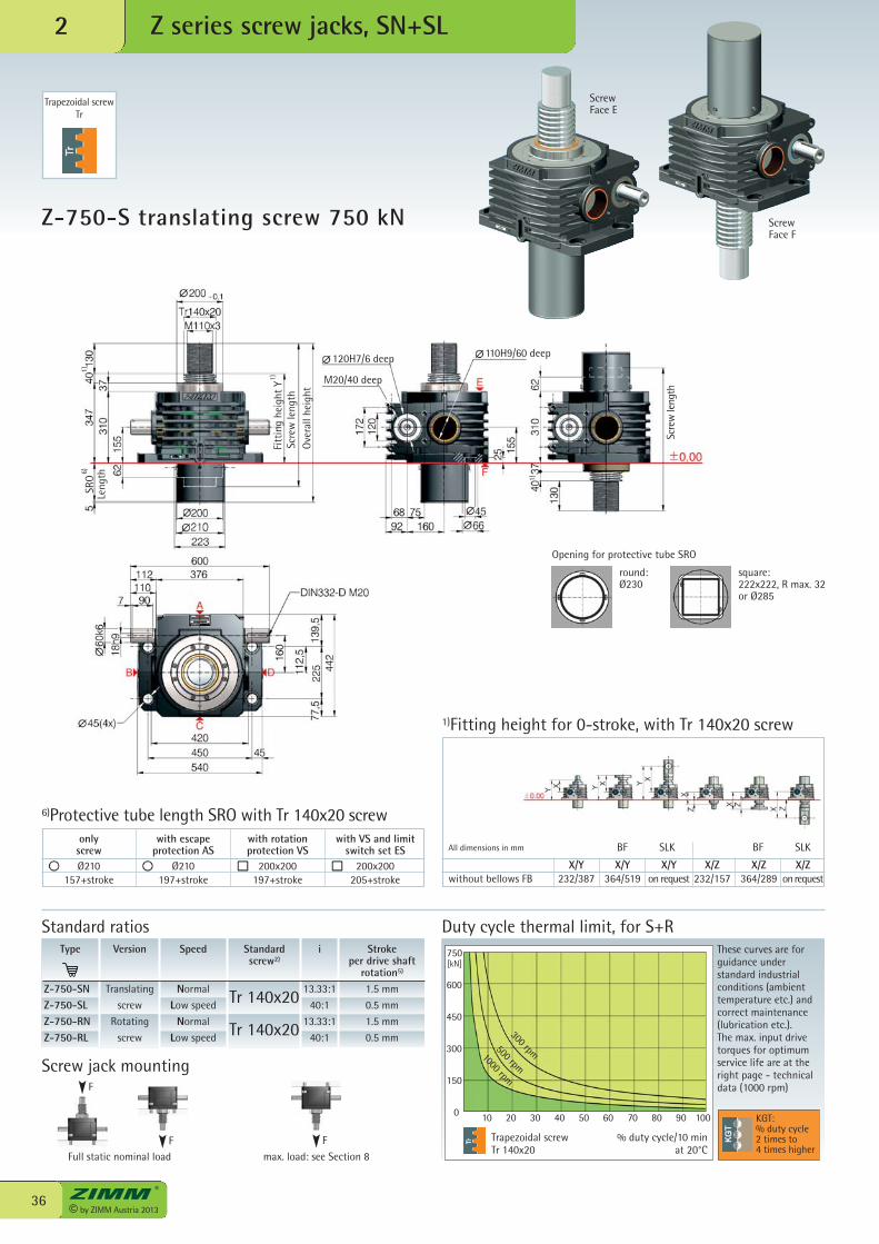
Z-750-S translating screw 750 kN
2
Trapezoidal screwTr 140x20
Duty cycle thermal limit, for S+RThese curves are forguidance understandard industrialconditions (ambienttemperature etc.) andcorrect maintenance(lubrication etc.). The max. input drivetorques for optimumservice life are at theright page - technicaldata (1000 rpm)
% duty cycle/10 min at 20°C
KGT:% duty cycle2 times to4 times higher
Trapezoidal screwTr
300 rpm500 rpm
1000 rpm
ScrewFace E
ScrewFace F
Z series screw jacks, SN+SL
1)Fitting height for 0-stroke, with Tr 140x20 screw
Type
Z-750-SNZ-750-SLZ-750-RNZ-750-RL
Speed
Normal
Low speed
Normal
Low speed
i
13.33:1
40:1
13.33:1
40:1
Stroke per drive shaft
rotation5)
1.5 mm
0.5 mm
1.5 mm
0.5 mm
Version
Translating
screw
Rotating
screw
Standardscrew2)
Tr 140x20
Tr 140x20
Standard ratios
600
450
300
150
120H7/6 deep
M20/40 deep
110H9/60 deep
Fitt
ing
heig
ht Y
Scre
w le
ngth
Ove
rall
heig
ht
Scre
w le
ngth
SRO
Leng
th6)
1)
X/Y X/Y X/Y X/Z X/Z X/Zwithout bellows FB 232/387 364/519 on request 232/157 364/289 onrequest
BF SLKAll dimensions in mm BF SLK
Opening for protective tube SRO
round:Ø230
square:222x222, R max. 32 or Ø285
with escapeprotection AS
Ø210197+stroke
with VS and limitswitch set ES
200x200205+stroke
with rotationprotection VS
200x200197+stroke
6)Protective tube length SRO with Tr 140x20 screwonly
screwØ210
157+stroke
1)
1)
Full static nominal load max. load: see Section 8
F
Screw jack mounting
F F
37© by ZIMM Austria 2013
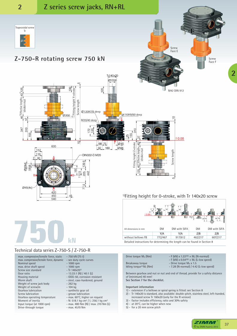
Z-750-R rotating screw 750 kN
max. compressive/tensile force, static - 750 kN (75 t)max. compressive/tensile force, dynamic - see duty cycle curvesNominal speed - 1000 rpmmax. drive shaft speed - 1000 rpmScrew size standard - Tr 140x202)
Gear ratio - 13.33:1 (N) / 40:1 (L)Housing material - GGG-50, corrosion-resistantWorm shaft - steel, case-hardened, groundWeight of screw jack body - 262 kgWeight of screw/m - 104 kgGearbox lubrication - synthetic gear oilScrew lubrication - grease lubricationGearbox operating temperature - max. 60°C, higher on requestMoment of inertia - N: 518.1 kg cm2 / L: 256.1 kg cm2
Input torque (at 1000 rpm) - max. 480 Nm (N) / max. 210 Nm (L)Drive-through torque - max. 4570 Nm
Drive torque MG (Nm) - F (kN) x 1.223)5) + ML (N-normal) - F (kN) x 0.543)5) + ML (L-low speed)Breakaway torque - Drive torque MG x 1.5Idling torque4) ML (Nm) - 7.28 (N-normal) / 4.42 (L-low speed)
Between gearbox and nut or nut and end of thread, provide for a safety distanceof (minimum) 40 mm!See Section 7 for the checklist.
Important information1) - extension if a bellows or spiral spring is fitted: see Section 82) - Tr 140x20 is standard, also available: double-pitch, stainless steel, left-handed,
increased screw Tr 160x20 (only for the R version)3) - factor includes efficiency, ratio and 30% safety4) - at 20°C, can be higher when new5) - for a 20 mm screw pitch
Technical data series Z-750-S / Z-750-R
2
Trapezoidal screwTr
2
M42 DIN 912
ScrewFace E
ScrewFace F
Z series screw jacks, RN+RL
1)Fitting height for 0-stroke, with Tr 140x20 screw
kN
Scre
w le
ngth
120H7/6 deep
M20/40 deep
Effe
ctiv
e le
ngth
=st
roke
+nut
Fitt
ing
heig
ht Y
+str
oke
Fitt
ing
heig
ht Z
+str
oke
110H9/60 deep
Scre
w le
ngth
Effe
ctive
leng
th=
stro
ke+n
ut
1)
Y/A Y/A Z/B Z/Bwithout bellows FB 772/467 917/612 462/217 607/217
Detailed instructions for determining the length can be found in Section 8
DM DM with SIFA DM DM with SIFAAll dimensions in mm
1)1)
1)1)
© by ZIMM Austria 201338
[kN]
0 10 20 30 40 50 60 70 80 90 100
1000
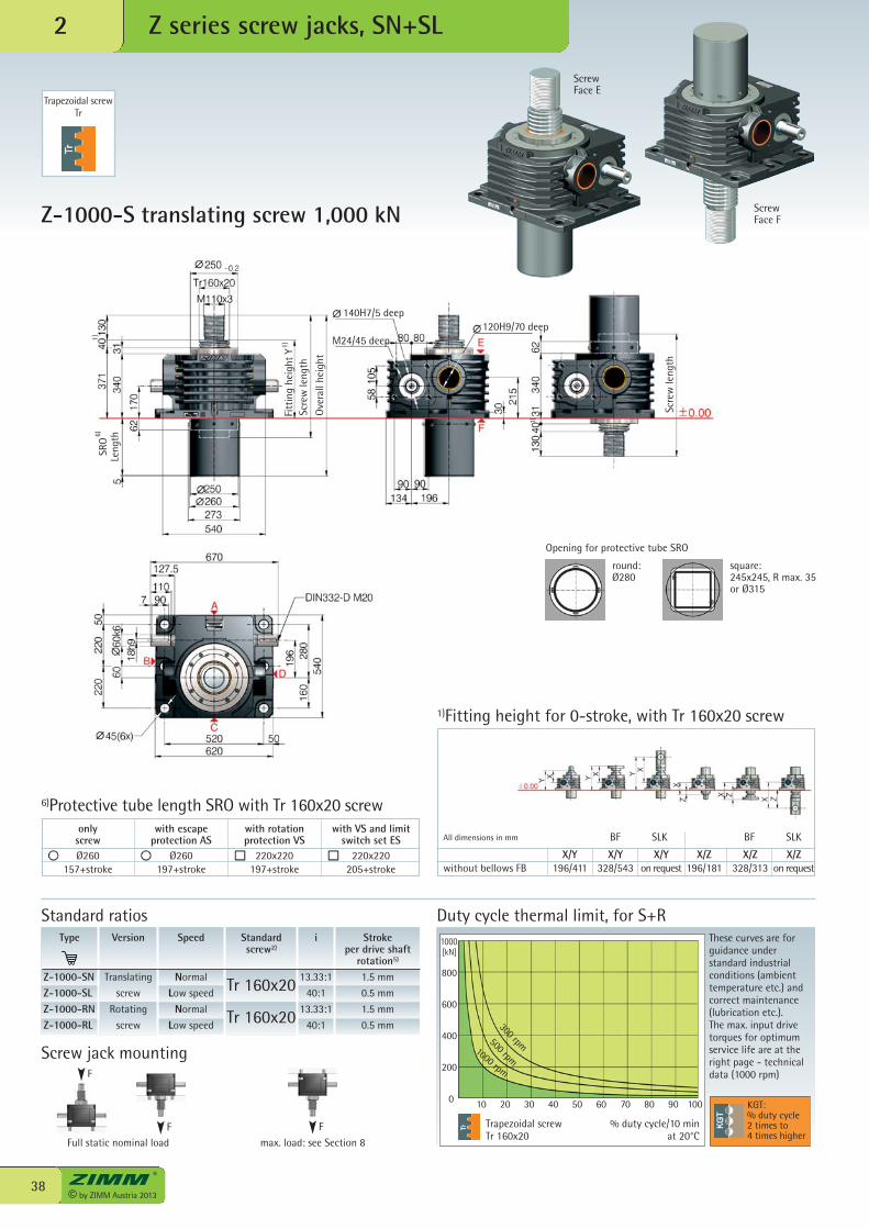
Z-1000-S translating screw 1,000 kN
2
Trapezoidal screwTr 160x20
Duty cycle thermal limit, for S+RThese curves are forguidance understandard industrialconditions (ambienttemperature etc.) andcorrect maintenance(lubrication etc.). The max. input drivetorques for optimumservice life are at theright page - technicaldata (1000 rpm)
% duty cycle/10 min at 20°C
KGT:% duty cycle2 times to4 times higher
Trapezoidal screwTr
300 rpm500 rpm1000 rpm
ScrewFace E
ScrewFace F
Z series screw jacks, SN+SL
1)Fitting height for 0-stroke, with Tr 160x20 screw
Type
Z-1000-SNZ-1000-SLZ-1000-RNZ-1000-RL
Speed
Normal
Low speed
Normal
Low speed
i
13.33:1
40:1
13.33:1
40:1
Stroke per drive shaft
rotation5)
1.5 mm
0.5 mm
1.5 mm
0.5 mm
Version
Translating
screw
Rotating
screw
Standardscrew2)
Tr 160x20
Tr 160x20
Standard ratios
800
600
400
200
140H7/5 deep
M24/45 deep120H9/70 deep
Fitt
ing
heig
ht Y
Scre
w le
ngth
Ove
rall
heig
ht
Scre
wle
ngth
SRO
Leng
th6)
1)
X/Y X/Y X/Y X/Z X/Z X/Zwithout bellows FB 196/411 328/543 on request 196/181 328/313 on request
BF SLKAll dimensions in mm BF SLK
Opening for protective tube SRO
round:Ø280
square:245x245, R max. 35 or Ø315
with escapeprotection AS
Ø260197+stroke
with VS and limitswitch set ES
220x220205+stroke
with rotationprotection VS
220x220197+stroke
6)Protective tube length SRO with Tr 160x20 screwonly
screwØ260
157+stroke
1)
1)
Full static nominal load max. load: see Section 8
F
Screw jack mounting
F F
39© by ZIMM Austria 2013
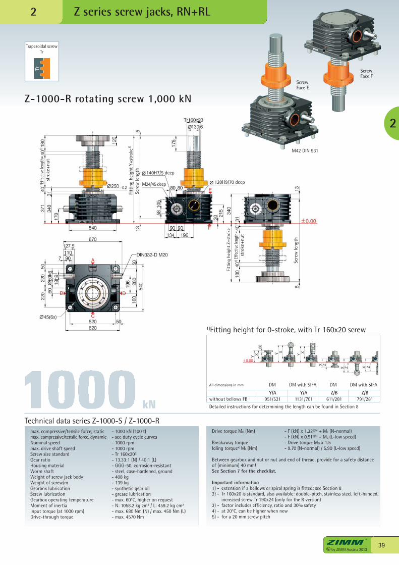
Z-1000-R rotating screw 1,000 kN
Z series screw jacks, RN+RL
max. compressive/tensile force, static - 1000 kN (100 t)max. compressive/tensile force, dynamic - see duty cycle curvesNominal speed - 1000 rpmmax. drive shaft speed - 1000 rpmScrew size standard - Tr 160x202)
Gear ratio - 13.33:1 (N) / 40:1 (L)Housing material - GGG-50, corrosion-resistantWorm shaft - steel, case-hardened, groundWeight of screw jack body - 408 kgWeight of screw/m - 139 kgGearbox lubrication - synthetic gear oilScrew lubrication - grease lubricationGearbox operating temperature - max. 60°C, higher on requestMoment of inertia - N: 1058.2 kg cm2 / L: 459.2 kg cm2
Input torque (at 1000 rpm) - max. 680 Nm (N) / max. 450 Nm (L)Drive-through torque - max. 4570 Nm
Drive torque MG (Nm) - F (kN) x 1.323)5) + ML (N-normal) - F (kN) x 0.513)5) + ML (L-low speed)Breakaway torque - Drive torque MG x 1.5Idling torque4) ML (Nm) - 9.70 (N-normal) / 5.90 (L-low speed)
Between gearbox and nut or nut and end of thread, provide for a safety distanceof (minimum) 40 mm!See Section 7 for the checklist.
Important information1) - extension if a bellows or spiral spring is fitted: see Section 82) - Tr 160x20 is standard, also available: double-pitch, stainless steel, left-handed,
increased screw Tr 190x24 (only for the R version)3) - factor includes efficiency, ratio and 30% safety4) - at 20°C, can be higher when new5) - for a 20 mm screw pitch
Technical data series Z-1000-S / Z-1000-R
2
Trapezoidal screwTr
2
1)Fitting height for 0-stroke, with Tr 160x20 screw
M42 DIN 931
ScrewFace E
ScrewFace F
kN
Scre
w le
ngth 140H7/5 deep
M24/45 deepEffe
ctive
leng
th=
stro
ke+n
ut
Fitt
ing
heig
ht Y
+str
oke
Fitt
ing
heig
ht Z
+str
oke
120H9/70 deep
Scre
w le
ngth
Effe
ctive
leng
th=
stro
ke+n
ut
1)
Y/A Y/A Z/B Z/Bwithout bellows FB 951/521 1131/701 611/281 791/281
Detailed instructions for determining the length can be found in Section 8
DM DM with SIFA DM DM with SIFAAll dimensions in mm
1)1)
1)1)
© by ZIMM Austria 201340 We have patents registered or pending for a range of functions and components.
PA
TENT
P E N D I NG
zum Patent
angemeldet
2 Z series screw jacks KGT
Z series screw jacks KGT2
41© by ZIMM Austria 2013
Pitch accuracy0.05 mm / 300 mmMaterial: 1.1213 (Cf 53), induction hardenedand polished.
No self-locking!Because of the lack of friction, a holding brakeis necessary: a motor brake or a springpressure brake is required.
Temperatures, duty cycleOperating temperature range -25°C to + 80°C.The duty cycle can be up to 4 times higherthan for trapezoidal screws (see diagrams), andat long strokes up to 2 times higher than fortrapezoidal screws.
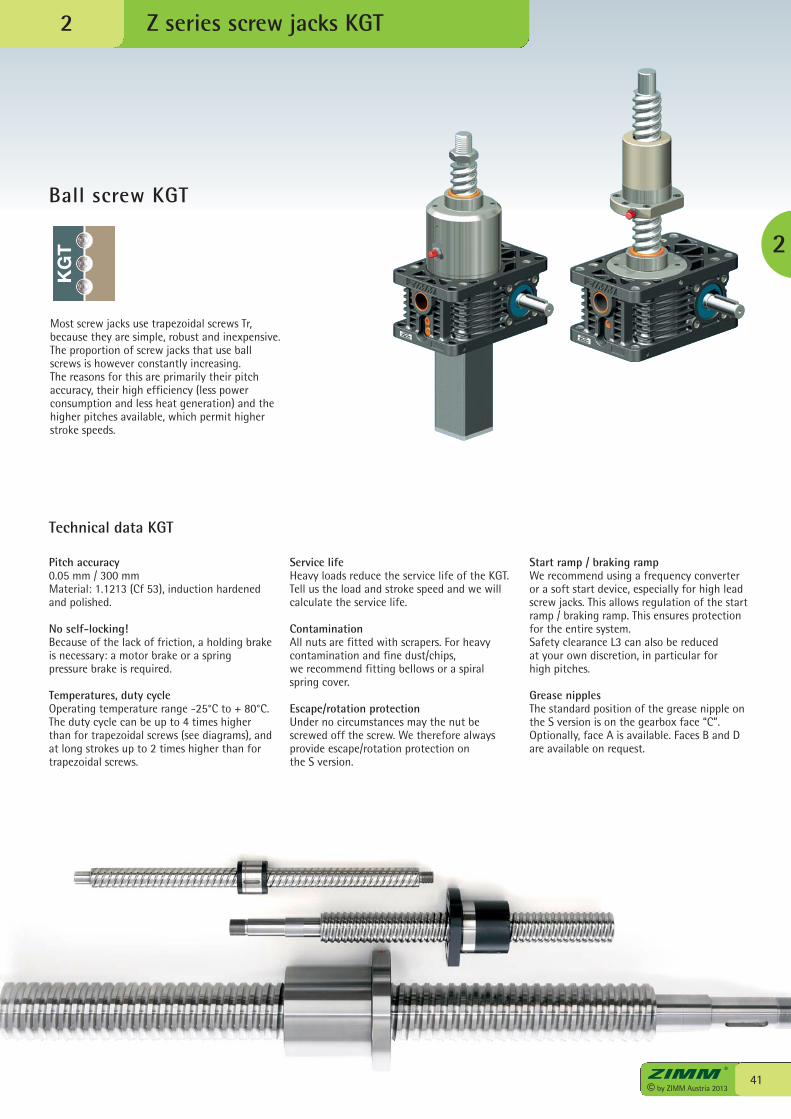
Most screw jacks use trapezoidal screws Tr,because they are simple, robust and inexpensive.The proportion of screw jacks that use ballscrews is however constantly increasing.The reasons for this are primarily their pitchaccuracy, their high efficiency (less powerconsumption and less heat generation) and thehigher pitches available, which permit higherstroke speeds.
Service lifeHeavy loads reduce the service life of the KGT.Tell us the load and stroke speed and we willcalculate the service life.
ContaminationAll nuts are fitted with scrapers. For heavycontamination and fine dust/chips,we recommend fitting bellows or a spiralspring cover.
Escape/rotation protectionUnder no circumstances may the nut bescrewed off the screw. We therefore alwaysprovide escape/rotation protection onthe S version.
Start ramp / braking rampWe recommend using a frequency converteror a soft start device, especially for high leadscrew jacks. This allows regulation of the startramp / braking ramp. This ensures protectionfor the entire system.Safety clearance L3 can also be reduced at your own discretion, in particular for high pitches.
Grease nipplesThe standard position of the grease nipple onthe S version is on the gearbox face “C”.Optionally, face A is available. Faces B and Dare available on request.
Technical data KGT
Ball screw KGT
2
KG
T
© by ZIMM Austria 201342
Z series screw jacks, KGT-S2
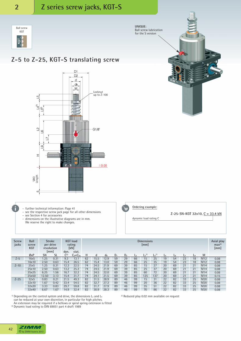
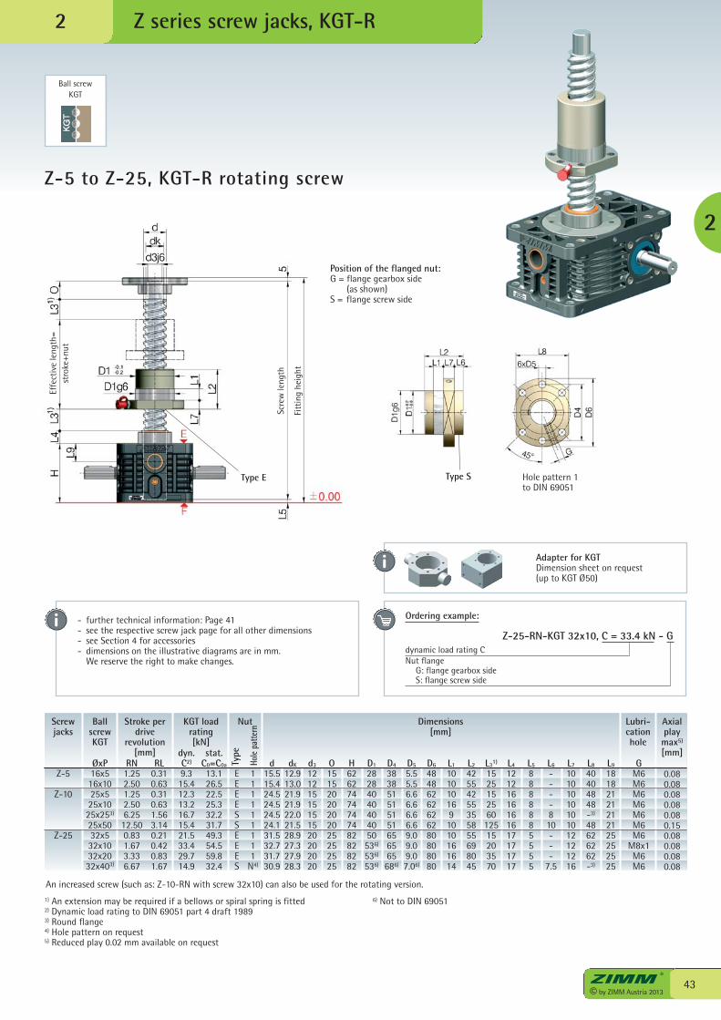
Z-5 to Z-25, KGT-S translating screw
Ball screwKGT
UNIQUE:Ball screw lubricationfor the S version
SL0.310.630.310.631.563.130.210.420.831.67
Screwjacks
BallscrewKGT
Stroke per driverevolution
[mm]SN
1.252.501.252.506.2512.500.831.673.336.67
ØxP16x516x1025x525x1025x2525x5032x532x1032x2032x40
stat.C0=C0a
13.126.522.525.332.231.749.354.559.832.4
KGT loadrating[kN]
dyn.C2)
9.315.412.313.216.715.421.533.429.714.9
1) Depending on the control system and drive, the dimensions L3 and L4
can be reduced at your own discretion, in particular for high pitches. An extension may be required if a bellows or spiral spring extension is fitted
2) Dynamic load rating to DIN 69051 part 4 draft 1989
5) Reduced play 0.02 mm available on request
- further technical information: Page 41- see the respective screw jack page for all other dimensions - see Section 4 for accessories- dimensions on the illustrative diagrams are in mm. We reserve the right to make changes.
Ordering example:
Z-25-SN-KGT 32x10, C = 33.4 kNdynamic load rating C
Z-5
Z-10
Z-25
Axial playmax5)
[mm]
Dimensions[mm]
H62627474747482828282
d15.515.424.524.524.524.131.532.731.730.9
dK
12.913.021.921.922.021.528.927.327.928.3
D1
59596969696989898989
D2
29293939393946464646
L2
66668585858599999999
L31)
152515256012515203570
L41)
253527377213731365186
L5
19192020202022222222
L6
54546969696982828282
L7
23232121212133333333
L9
18182121212125252525
MM12M12M14M14M14M14M20M20M20M20
0.080.080.080.080.080.150.080.080.080.08
SRO
Leng
th
Locknutup to Z-100
43© by ZIMM Austria 2013
Z series screw jacks, KGT-R
2
Z-5 to Z-25, KGT-R rotating screw
Ball screwKGT
- further technical information: Page 41- see the respective screw jack page for all other dimensions - see Section 4 for accessories- dimensions on the illustrative diagrams are in mm. We reserve the right to make changes.
Ordering example:
Z-25-RN-KGT 32x10, C = 33.4 kN - Gdynamic load rating CNut flange G: flange gearbox side S: flange screw side
Type E Type S Hole pattern 1to DIN 69051
1) An extension may be required if a bellows or spiral spring is fitted2) Dynamic load rating to DIN 69051 part 4 draft 19893) Round flange4) Hole pattern on request5) Reduced play 0.02 mm available on request
6) Not to DIN 69051
An increased screw (such as: Z-10-RN with screw 32x10) can also be used for the rotating version.
Screwjacks
BallscrewKGT
Stroke perdrive
revolution[mm]
RN1.252.501.252.506.2512.500.831.673.336.67
ØxP16x516x1025x525x1025x253)
25x5032x532x1032x2032x403)
Z-5
Z-10
Z-25
stat.C0=C0a
13.126.522.525.332.231.749.354.559.832.4
KGT loadrating[kN]
dyn.C2)
9.315.412.313.216.715.421.533.429.714.9
RL0.310.630.310.631.563.140.210.420.831.67
EEEESSEEES
Type
Hole
patte
rn
Nut
111111111
N4)
Axialplaymax5)
[mm]
Dimensions[mm]
d15.515.424.524.524.524.131.532.731.730.9
d3
12121515151520202020
dK
12.913.021.921.922.021.528.927.327.928.3
O15152020202025252525
H62627474747482828282
D1
28284040404050536)
536)
536)
D4
383851515151656565686)
D5
5.55.56.66.66.66.69.09.09.07.06)
D6
48486262626280808080
L1
1010101691010161614
L2
42554255355855698045
L31)
152515256012515203570
L4
12121616161617171717
L5
8888885555
L6
----810---
7.5
L7
10101010101012121216
L8
40404848-3)
48626262-3)
L9
18182121212125252525
GM6M6M6M6M6M6M6
M8x1M6M6
Lubri-cationhole
0.080.080.080.080.080.150.080.080.080.08
Position of the flanged nut:G = flange gearbox side (as shown)S = flange screw side
2
Adapter for KGTDimension sheet on request (up to KGT Ø50)
Effe
ctiv
e le
ngth
=st
roke
+nut
Scre
wle
ngth
Fitt
ing
heig
ht
© by ZIMM Austria 201344
Z series screw jacks, KGT-S2
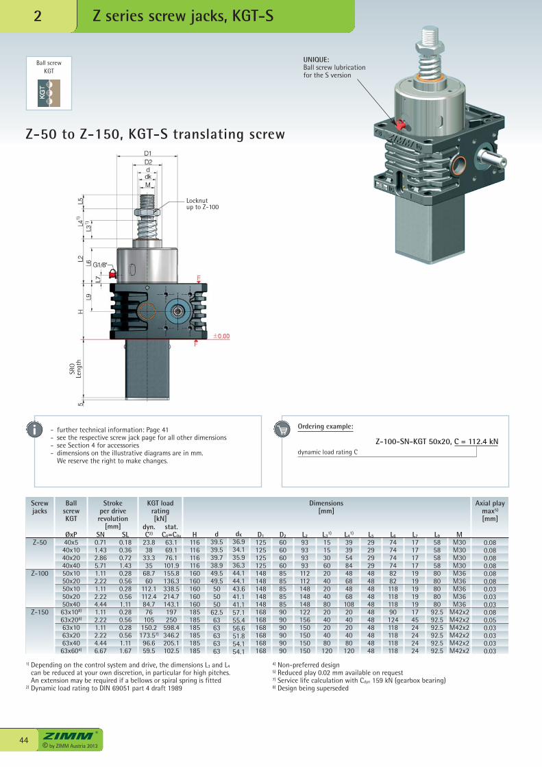
Z-50 to Z-150, KGT-S translating screw
Ball screwKGT
SL0.180.360.721.430.280.560.280.561.110.280.560.280.561.111.67
stat.C0=C0a
63.169.176.1101.9155.8136.3338.5214.7143.1197250
598.4346.2205.1102.5
KGT loadrating[kN]
Screwjacks
BallscrewKGT
Stroke per driverevolution
[mm]SN0.711.432.865.711.112.221.112.224.441.112.221.112.224.446.67
ØxP40x540x1040x2040x4050x1050x2050x1050x2050x4063x108)
63x208)
63x1063x2063x4063x604)
dyn.C2)
23.838
33.335
68.760
112.1112.484.776105
150.2173.57)
96.659.5
Z-50
Z-100
Z-150
UNIQUE:Ball screw lubricationfor the S version
Axial playmax5)
[mm]
Dimensions[mm]
H116116116116160160160160160185185185185185185
d39.539.539.738.949.549.5505050
62.56363636363
dK
36.934.135.936.344.144.143.641.141.157.155.456.651.854.154.1
D1
125125125125148148148148148168168168168168168
D2
606060608585858585909090909090
L2
93939393112112148148148122156150150150150
L31)
1515306020402040802040204080120
L41)
39395484486848681082040204080120
L5
292929294848484848484848484848
L6
74747474828211811811890124118118118118
L7
171717171919191919174524242424
L9
585858588080808080
92.592.592.592.592.592.5
MM30M30M30M30M36M36M36M36M36
M42x2M42x2M42x2M42x2M42x2M42x2
0.080.080.080.080.080.080.030.030.030.080.050.030.030.030.03
1) Depending on the control system and drive, the dimensions L3 and L4
can be reduced at your own discretion, in particular for high pitches. An extension may be required if a bellows or spiral spring is fitted
2) Dynamic load rating to DIN 69051 part 4 draft 1989
4) Non-preferred design5) Reduced play 0.02 mm available on request7) Service life calculation with Cdyn 159 kN (gearbox bearing)8) Design being superseded
- further technical information: Page 41- see the respective screw jack page for all other dimensions - see Section 4 for accessories- dimensions on the illustrative diagrams are in mm. We reserve the right to make changes.
Ordering example:
Z-100-SN-KGT 50x20, C = 112.4 kNdynamic load rating C
SRO
Leng
th
Locknutup to Z-100
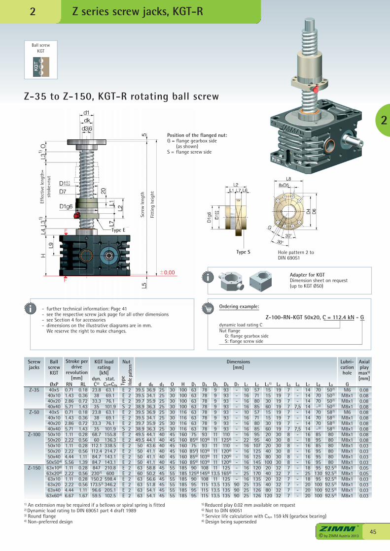
45© by ZIMM Austria 2013
Z series screw jacks, KGT-R
2
Z-35 to Z-150, KGT-R rotating ball screw
Ball screwKGT
2
Position of the flanged nut:G = flange gearbox side (as shown)S = flange screw side
Type S Hole pattern 2 toDIN 69051
1) An extension may be required if a bellows or spiral spring is fitted2) Dynamic load rating to DIN 69051 part 4 draft 19893) Round flange4) Non-preferred design
5) Reduced play 0.02 mm available on request6) Not to DIN 690517) Service life calculation with Cdyn 159 kN (gearbox bearing)8) Design being superseded
- further technical information: Page 41- see the respective screw jack page for all other dimensions - see Section 4 for accessories- dimensions on the illustrative diagrams are in mm. We reserve the right to make changes.
Ordering example:
Z-100-RN-KGT 50x20, C = 112.4 kN - Gdynamic load rating CNut flange G: flange gearbox side S: flange screw side
Adapter for KGTDimension sheet on request (up to KGT Ø50)
Type E
Effe
ctiv
e le
ngth
=st
roke
+nut
Scre
w le
ngth
Fitt
ing
heig
ht
Screwjacks
BallscrewKGT
RN0.711.432.865.710.711.432.865.711.112.221.112.224.445.561.112.221.112.224.446.67
ØxP40x540x1040x2040x4040x540x1040x2040x4050x1050x2050x1050x2050x4050x504)
63x108)
63x208)
63x1063x2063x4063x604)
Z-35
Z-50
Z-100
Z-150
RL0.180.360.721.430.180.360.721.430.280.560.280.561.111.390.280.560.280.561.111.67
EEESEEESEEEEEEEEEEEE
Axialplaymax5)
[mm]
Type
Hole
patte
rn
Dimensions[mm]
d39.539.539.738.939.539.539.738.949.549.550505050636063636363
d3
2525252525252525404040404040454545454545
dK
36.934.135.936.336.934.135.936.344.144.143.641.141.141.158.850.256.651.854.154.1
O3030303030303030454545454545555555555555
H100100100100116116116116160160160160160160185185185185185185
D1
636363636363636375856)
75856)856)
856)
901256)
90959595
D4
787878787878787893
1036)
931036)
1036)
1036)
1081456)
108115115115
D5
9999999911111111111111
13.511
13.513.513.5
D6
9393939393939393110
1256)
1101206)
1206)
1206)
1251656)
125135135135
D7
-----------------
909090
L1
1016161610161616162216161616162516252525
L2
57718085577180859595107125125145120170135135126126
L31)
151530601515306020402040801002040204080120
L4
1919191919191919303030303030323232323232
L5
77777777888888777777
L6
---
7,5---
7,5------------
L7
1414141414141414161816161616182518202020
L8
707070-3)
707070-3)
8595859595959513095100100100
L9
507)
507)
507)
507)
587)
587)
587)
587)
808080808080
92.57)
92.57)
92.57)
92.57)
92.57)
92.57)
GM6
M8x1M8x1M8x1M6
M8x1M8x1M8x1M8x1M8x1M8x1M8x1M8x1M8x1M8x1M8x1M8x1M8x1M8x1M8x1
Lubri-cationhole
Nut
22222222222222222222
0.080.080.080.080.080.080.080.080.080.080.030.030.030.030.050.050.030.030.030.03
stat.C0=C0a
63.169.176.1101.963.169.176.1101.9155.8136.3338.5214.7143.1143.1210.8600
598.4346.2205.1102.5
KGT loadrating[kN]
dyn.C2)
23.838
33.335
23.838
33.335
68.760
112.1112.484.784.78472307)
150.2173.57)
96.659.5
Stroke perdrive
revolution[mm]
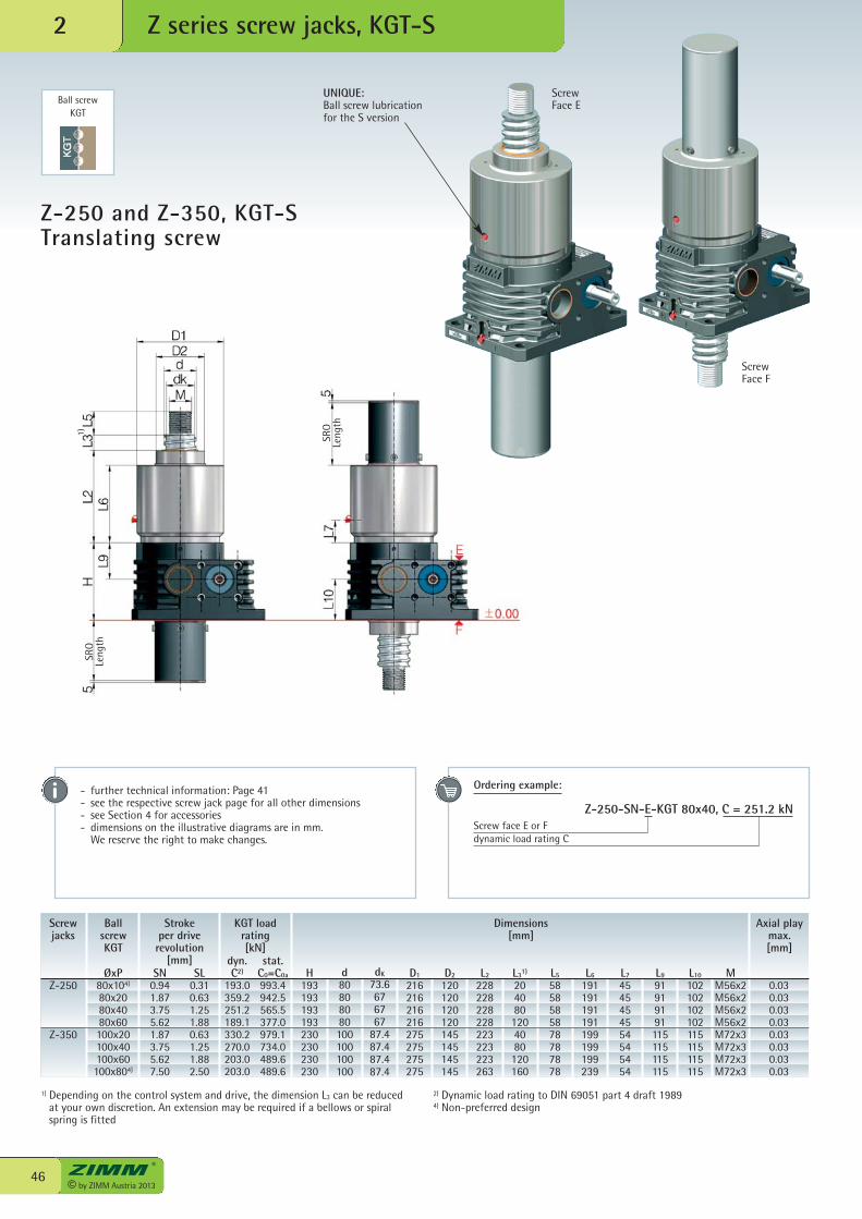
© by ZIMM Austria 201346
Z series screw jacks, KGT-S2
Ball screwKGT
SL0.310.631.251.880.631.251.882.50
Axial playmax.[mm]
Dimensions[mm]
Screwjacks
BallscrewKGT
Stroke per driverevolution
[mm]SN
0.941.873.755.621.873.755.627.50
ØxP80x104)
80x2080x4080x60100x20100x40100x60100x804)
Z-250
Z-350
UNIQUE:Ball screw lubricationfor the S version
ScrewFace E
ScrewFace F
H193193193193230230230230
d80808080100100100100
dK
73.6676767
87.487.487.487.4
D1
216216216216275275275275
D2
120120120120145145145145
L2
228228228228223223223263
L31)
2040801204080120160
L5
5858585878787878
L6
191191191191199199199239
L7
4545454554545454
L9
91919191115115115115
L10
102102102102115115115115
MM56x2M56x2M56x2M56x2M72x3M72x3M72x3M72x3
0.030.030.030.030.030.030.030.03
stat.C0=C0a
993.4942.5565.5377.0979.1734.0489.6489.6
KGT loadrating[kN]
dyn.C2)
193.0359.2251.2189.1330.2270.0203.0203.0
1) Depending on the control system and drive, the dimension L3 can be reducedat your own discretion. An extension may be required if a bellows or spiralspring is fitted
2) Dynamic load rating to DIN 69051 part 4 draft 19894) Non-preferred design
Z-250 and Z-350, KGT-S Translating screw
- further technical information: Page 41- see the respective screw jack page for all other dimensions - see Section 4 for accessories- dimensions on the illustrative diagrams are in mm. We reserve the right to make changes.
Ordering example:
Z-250-SN-E-KGT 80x40, C = 251.2 kNScrew face E or Fdynamic load rating C
SRO
Leng
th
SRO
Leng
th
1)
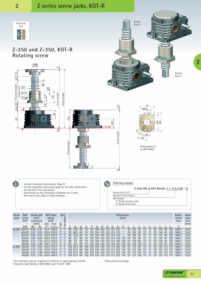
47© by ZIMM Austria 2013
Z series screw jacks, KGT-R
2
Z-250 and Z-350, KGT-R Rotating screw
Ball screwKGT
2
Hole pattern 2to DIN 69051
Screwjacks
BallscrewKGT
Stroke perdrive
revolution[mm]
RN0.941.870.941.873.755.621.873.755.627.50
ØxP80x104)
80x204)
80x104)
80x2080x4080x60100x20100x40100x60100x80
RL0.310.630.310.631.251.880.631.251.882.50
Z-250
Z-350
ScrewFace E
ScrewFace F
EEEEEEEEEE
Axialplaymax[mm]
Type
Hole
patte
rn
Dimensions[mm]
d807880808080100100100100
dK
75.868.273.6676767
87.487.487.487.4
d3
60606060606080808080
O757575757575100100100100
H193193193193193193230230230230
Hu
204204204204204204230230230230
D1
105135105125125125150150150150
D4
125155125145145145176176176176
D5
13.513.513.513.513.513.517.517.517.517.5
D6
145175145165165165202202202202
D7
---
120120120145145145145
L1
16251625252525252525
L2
120190160190190190175175175215
L3
20402040801204080120160
L4
37373737373724242424
L5
5555556666
L7
20252025252530303030
L8
110140110130130130155155155155
L9
919191919191115115115115
L10
102102102102102102115115115115
GM8x1M8x1M8x1M8x1M8x1M8x1M8x1M8x1M8x1M8x1
0.050.050.030.030.030.030.030.030.030.03
Lubri-cationhole
Nut
2222222222
stat.C0=C0a
269.2820.0993.4942.5565.5377.0979.1734.0489.6489.6
KGT loadrating[kN]
dyn.C2)
93.4320.0193.0359.2251.2189.1330.2270.0203.0203.0
1) An extension may be required if a bellows or spiral spring is fitted2) Dynamic load rating to DIN 69051 part 4 draft 1989
4) Non-preferred design
- further technical information: Page 41- see the respective screw jack page for all other dimensions - see Section 4 for accessories- dimensions on the illustrative diagrams are in mm. We reserve the right to make changes.
Ordering example:
Z-250-RN-E-KGT 80x40, C = 112.4 kN - GScrew face E or Fdynamic load rating CNut flange G: flange gearbox side S: flange screw side
Effe
ctiv
e le
ngth
=st
roke
+nut
Scre
wle
ngth
Fitt
ing
heig
ht
Scre
wle
ngth
Fitt
ing
heig
ht
1)1)
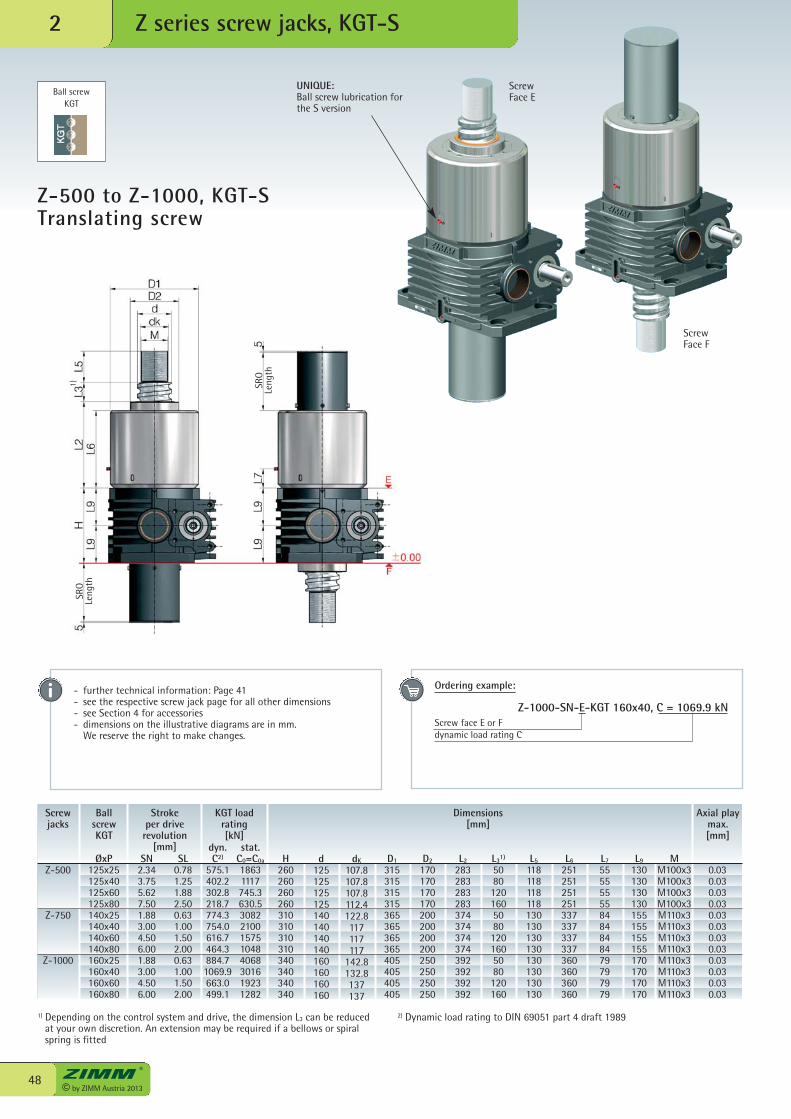
© by ZIMM Austria 201348
Z series screw jacks, KGT-S2
Z-500 to Z-1000, KGT-STranslating screw
Ball screwKGT
UNIQUE:Ball screw lubrication forthe S version
1) Depending on the control system and drive, the dimension L3 can be reducedat your own discretion. An extension may be required if a bellows or spiralspring is fitted
SL0.781.251.882.500.631.001.502.000.631.001.502.00
Axial playmax.[mm]
Dimensions[mm]
Screwjacks
BallscrewKGT
Stroke per driverevolution
[mm]SN
2.343.755.627.501.883.004.506.001.883.004.506.00
ØxP125x25125x40125x60125x80140x25140x40140x60140x80160x25160x40160x60160x80
Z-500
Z-750
Z-1000
H260260260260310310310310340340340340
d125125125125140140140140160160160160
dK
107.8107.8107.8112.4122.8117117117
142.8132.8137137
D1
315315315315365365365365405405405405
D2
170170170170200200200200250250250250
L2
283283283283374374374374392392392392
L31)
508012016050801201605080120160
L5
118118118118130130130130130130130130
L6
251251251251337337337337360360360360
L7
555555558484848479797979
L9
130130130130155155155155170170170170
MM100x3M100x3M100x3M100x3M110x3M110x3M110x3M110x3M110x3M110x3M110x3M110x3
0.030.030.030.030.030.030.030.030.030.030.030.03
stat.C0=C0a
18631117745.3630.530822100157510484068301619231282
KGT loadrating[kN]
dyn.C2)
575.1402.2302.8218.7774.3754.0616.7464.3884.71069.9663.0499.1
2) Dynamic load rating to DIN 69051 part 4 draft 1989
ScrewFace E
ScrewFace F
- further technical information: Page 41- see the respective screw jack page for all other dimensions - see Section 4 for accessories- dimensions on the illustrative diagrams are in mm. We reserve the right to make changes.
Ordering example:
Z-1000-SN-E-KGT 160x40, C = 1069.9 kNScrew face E or Fdynamic load rating C
SRO
Leng
th
SRO
Leng
th
1)
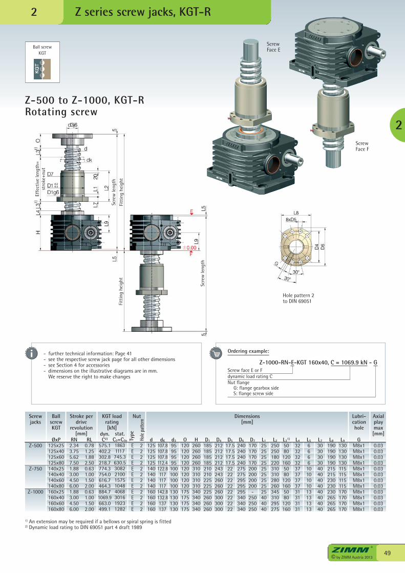
49© by ZIMM Austria 2013
Z series screw jacks, KGT-R
2
Z-500 to Z-1000, KGT-R Rotating screw
2
Ball screwKGT
Hole pattern 2to DIN 69051
Screwjacks
BallscrewKGT
Stroke perdrive
revolution[mm]
RN2.343.755.627.501.883.004.506.001.883.004.506.00
ØxP125x25125x40125x60125x80140x25140x40140x60140x80160x25160x40160x60160x80
RL0.781.251.882.500.631.001.502.000.631.001.502.00
EEEEE EEEEEEE
Axialplaymax[mm]
Type
Hole
patte
rn
Dimensions[mm]
d125125125125140140140140160160160160
dK
107.8107.8107.8112.4122.8117117117
142.8132.8137137
d3
95959595100100100100130130130130
O120120120120120120120120175175175175
H260260260260310310310310340340340340
D1
185185185185210210225225225260260260
D4
212212212212243243260260260300300300
D5
17.517.517.517.52222222222222222
D6
240240240240275275295295295340340340
D7
170170170170200200200200
-250250250
L1
252525252525252525404040
L2
250250180220310310280260345310295275
L31)
508012016050801201605080120160
L4
323232323737373731313131
L5
66661010101013131313
L7
303030304040404040404040
L8
190190190190215215230230230265265265
L9
130130130130115115115115170170170170
GM8x1M8x1M8x1M8x1M8x1M8x1M8x1M8x1M8x1M8x1M8x1M8x1
0.030.030.030.030.030.030.030.030.030.030.030.03
Lubri-cationhole
Nut
222222222222
stat.C0=C0a
18631117745.3630.530822100157510484068301619231282
KGT loadrating[kN]
dyn.C2)
575.1402.2302.8218.7774.3754.0616.7464.3884.71069.9663.0499.1
Z-500
Z-750
Z-1000
1) An extension may be required if a bellows or spiral spring is fitted2) Dynamic load rating to DIN 69051 part 4 draft 1989
ScrewFace E
ScrewFace F
- further technical information: Page 41- see the respective screw jack page for all other dimensions - see Section 4 for accessories- dimensions on the illustrative diagrams are in mm. We reserve the right to make changes
Ordering example:
Z-1000-RN-E-KGT 160x40, C = 1069.9 kN - GScrew face E or Fdynamic load rating CNut flange G: flange gearbox side S: flange screw side
Effe
ctiv
e le
ngth
=st
roke
+nut
Scre
wle
ngth
Fitt
ing
heig
ht
Scre
wle
ngth
Fitt
ing
heig
ht
1)1)
© by ZIMM Austria 201350 We have patents registered or pending for a range of functions and components.
PA
TENT
P E N D I NG
zum Patent
angemeldet
Z series screw jacks, SIFA2
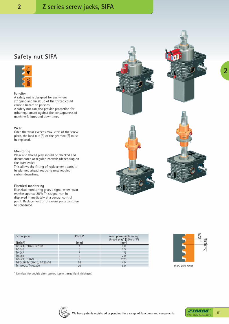
Z series screw jacks, SIFA
51© by ZIMM Austria 2013
2
Safety nut SIFA
FunctionA safety nut is designed for use wherestripping and break up of the thread couldcause a hazard to persons.A safety nut can also provide protection forother equipment against the consequences ofmachine failures and downtimes.
WearOnce the wear exceeds max. 25% of the screwpitch, the load nut (R) or the gearbox (S) mustbe replaced.
MonitoringWear and thread play should be checked anddocumented at regular intervals (depending onthe duty cycle).This allows the fitting of replacement parts tobe planned ahead, reducing unscheduledsystem downtime.
Electrical monitoringElectrical monitoring gives a signal when wearreaches approx. 25%. This signal can bedisplayed immediately at a central controlpoint. Replacement of the worn parts can thenbe scheduled.
Screw jacks Pitch P max. permissible wear/ thread play* (25% of P)[TrØxP] [mm] [mm]Tr16x4, Tr18x4, Tr20x4 4 1.0Tr30x6 6 1.5Tr40x7 7 1.75Tr50x8 8 2.0Tr55x9, Tr60x9 9 2.25Tr80x16, Tr100x16, Tr120x16 16 4.0Tr140x20, Tr160x20 20 5.0
* Identical for double pitch screws (same thread flank thickness)
max. 25% wear
2
We have patents registered or pending for a range of functions and components.
PA
TENT
P E N D I NG
zum Patent
angemeldet
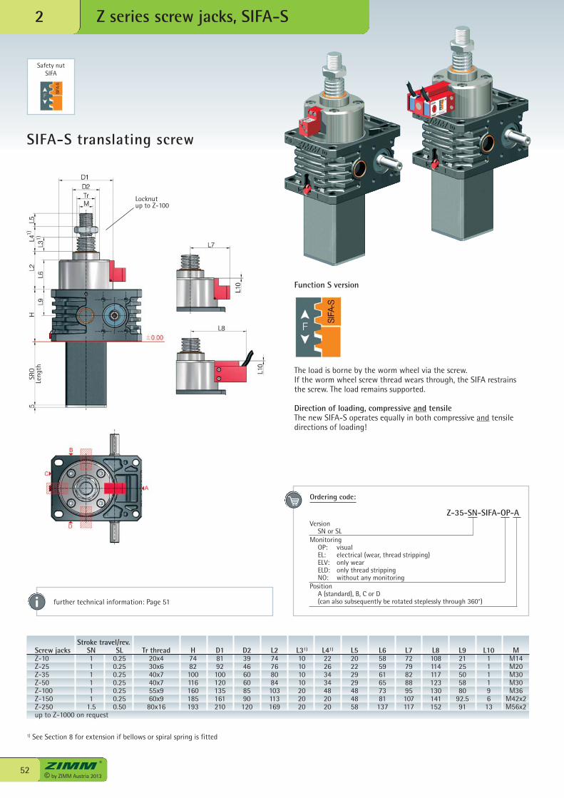
Locknutup to Z-100
© by ZIMM Austria 201352
Z series screw jacks, SIFA-S2
SIFA-S translating screw
Safety nutSIFA
Function S version
The load is borne by the worm wheel via the screw.If the worm wheel screw thread wears through, the SIFA restrainsthe screw. The load remains supported.
Direction of loading, compressive and tensileThe new SIFA-S operates equally in both compressive and tensiledirections of loading!
further technical information: Page 51
Ordering code:
Z-35-SN-SIFA-OP-AVersion SN or SLMonitoring OP: visual EL: electrical (wear, thread stripping) ELV: only wear ELD: only thread stripping NO: without any monitoringPosition A (standard), B, C or D (can also subsequently be rotated steplessly through 360°)
Stroke travel/rev. Screw jacks SN SL Tr thread H D1 D2 L2 L31) L41) L5 L6 L7 L8 L9 L10 M Z-10 1 0.25 20x4 74 81 39 74 10 22 20 58 72 108 21 1 M14 Z-25 1 0.25 30x6 82 92 46 76 10 26 22 59 79 114 25 1 M20 Z-35 1 0.25 40x7 100 100 60 80 10 34 29 61 82 117 50 1 M30 Z-50 1 0.25 40x7 116 120 60 84 10 34 29 65 88 123 58 1 M30 Z-100 1 0.25 55x9 160 135 85 103 20 48 48 73 95 130 80 9 M36 Z-150 1 0.25 60x9 185 161 90 113 20 20 48 81 107 141 92.5 6 M42x2 Z-250 1.5 0.50 80x16 193 210 120 169 20 20 58 137 117 152 91 13 M56x2 up to Z-1000 on request
1) See Section 8 for extension if bellows or spiral spring is fitted
SRO
Leng
th1)
1)
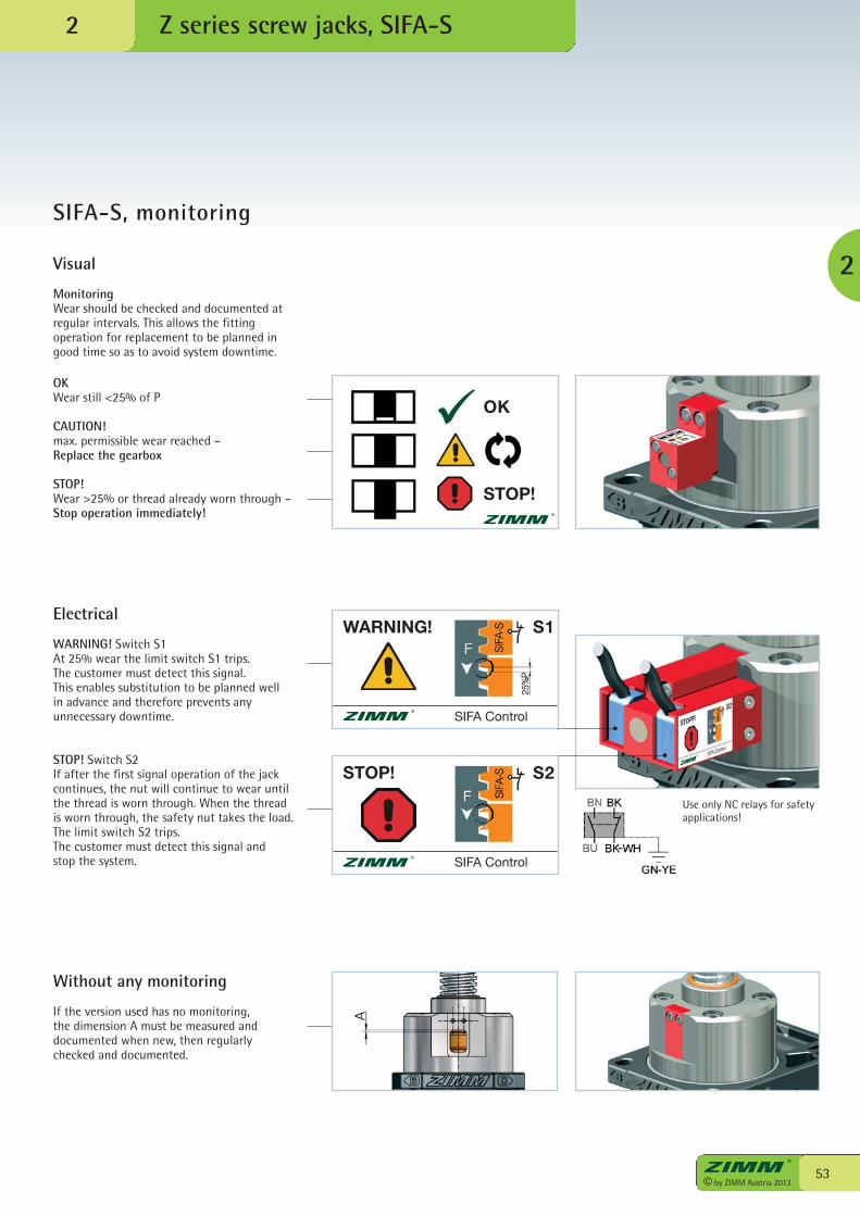
53© by ZIMM Austria 2013
2
2
Visual
MonitoringWear should be checked and documented atregular intervals. This allows the fittingoperation for replacement to be planned ingood time so as to avoid system downtime.
Electrical
WARNING! Switch S1At 25% wear the limit switch S1 trips.The customer must detect this signal.This enables substitution to be planned wellin advance and therefore prevents anyunnecessary downtime.
STOP! Switch S2If after the first signal operation of the jackcontinues, the nut will continue to wear untilthe thread is worn through. When the threadis worn through, the safety nut takes the load.The limit switch S2 trips.The customer must detect this signal and stop the system.
Without any monitoring
If the version used has no monitoring,the dimension A must be measured anddocumented when new, then regularlychecked and documented.
OKWear still <25% of P
CAUTION!max. permissible wear reached –Replace the gearbox
STOP!Wear >25% or thread already worn through –Stop operation immediately!
Z series screw jacks, SIFA-S
SIFA-S, monitoring
WARNING!
SIFA Control
STOP!
SIFA Control
Use only NC relays for safetyapplications!
OK
STOP!
S1
S2
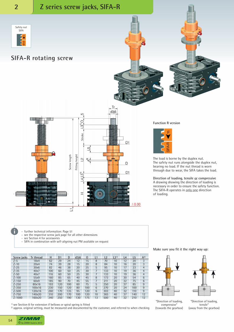
© by ZIMM Austria 201354
2
SIFA-R rotating screw
Safety nutSIFA
Function R version
The load is borne by the duplex nut.The safety nut runs alongside the duplex nut,bearing no load. If the nut thread is wornthrough due to wear, the SIFA takes the load.
Direction of loading, tensile or compressiveA drawing showing the direction of loading isnecessary in order to ensure the safety function.The SIFA-R operates in only one directionof loading.
Make sure you fit it the right way up:
“Direction of loading,compressive”
(towards the gearbox)
“Direction of loading,tensile”
(away from the gearbox)
Screw jacks Tr thread H D1 D d3j6 O L1 L2 L31) L4 L5 A2)
Z-5 18x4 62 29 24 12 15 8 70 10 12 20 3 Z-10 20x4 74 39 28 15 20 8 84 10 16 20 3 Z-25 30x6 82 46 38 20 25 5 95 10 17 23 4 Z-35 40x7 100 60 50 25 30 7 133 10 19 36 4 Z-50 40x7 116 60 50 25 30 7 133 10 19 36 4 Z-100 55x9 160 85 65 40 45 8 173 20 30 54 6 Z-150 60x9 185 90 70 45 55 7 211 20 32 75 6 Z-250 80x16 193 120 100 60 75 5 250 20 37 85 9 Z-350 100x16 230 150 120 80 100 6 270 20 24 100 9 Z-500 120x16 260 170 135 95 120 6 303 40 32 110 9 Z-750 140x20 310 200 170 100 120 10 365 40 37 140 12 Z-1000 160x20 340 250 190 130 175 13 500 40 32 210 12
1) see Section 8 for extension if bellows or spiral spring is fitted2) approx. original setting, must be measured and documented by the customer, and referred to when checking
- further technical information: Page 51- see the respective screw jack page for all other dimensions- see Section 4 for accessories- SIFA in combination with self-aligning nut PM available on request
Z series screw jacks, SIFA-R
Scre
wle
ngth
Fitt
ing
heig
ht
Stro
ke
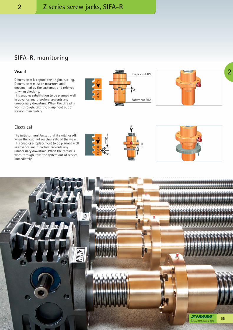
55© by ZIMM Austria 2013
Z series screw jacks, SIFA-R
2
SIFA-R, monitoring
2
Visual
Dimension A is approx. the original setting.Dimension A must be measured anddocumented by the customer, and referredto when checking.This enables substitution to be planned wellin advance and therefore prevents anyunnecessary downtime. When the thread isworn through, take the equipment out ofservice immediately.
Electrical
The initiator must be set that it switches offwhen the load nut reaches 25% of the wear.This enables a replacement to be planned wellin advance and therefore prevents anyunnecessary downtime. When the thread isworn through, take the system out of serviceimmediately.
Duplex nut DM
Safety nut SIFA
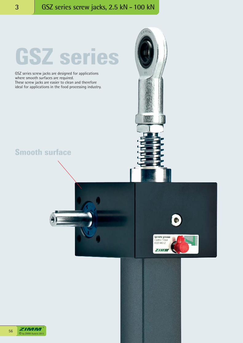
© by ZIMM Austria 201356
GSZ series screw jacks, 2.5 kN -100 kN 3
GSZ seriesGSZ series screw jacks are designed for applicationswhere smooth surfaces are required.These screw jacks are easier to clean and thereforeideal for applications in the food processing industry.
Smooth surface
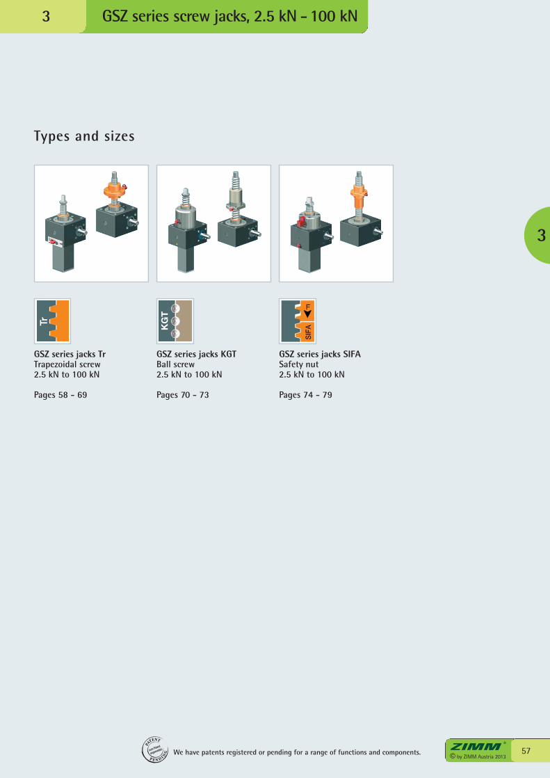
GSZ series screw jacks, 2.5 kN -100 kN 3
57© by ZIMM Austria 2013
Types and sizes
3
GSZ series jacks TrTrapezoidal screw2.5 kN to 100 kN
Pages 58 - 69
GSZ series jacks KGTBall screw2.5 kN to 100 kN
Pages 70 - 73
GSZ series jacks SIFASafety nut 2.5 kN to 100 kN
Pages 74 - 79
We have patents registered or pending for a range of functions and components.
PA
TENT
P E N D I NG
zum Patent
angemeldet
KG
T
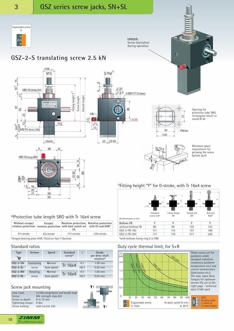
6890 Lustenau/Austriahttp://www.zimm.at
Type: GSZ-2-SNstatic: 2,5 kN ratio: i=4:1n, mom: 1500 rpm n, max: 3000 rpmserial-no: L-Z01-0013567
© by ZIMM Austria 201358
[kN]
0 10 20 30 40 50 60 70 80 90 100
2.5
2.0
1.5
1.0
0.5
GSZ-2-S translating screw 2.5 kN
GSZ series screw jacks, SN+SL3
max. load: 2.5 kN compressive and tensile loadScrew: M6, strength class 8.8Screw-in depth: 8 to 10 mmTightening torque: 8 NmScrew locking: with Loctite 243
Screw jack mounting
*Hinged bearing plate KAR, fitted on face F (below).
6)Protective tube length SRO with Tr 16x4 screw
Trapezoidal screwTr 16x4
Duty cycle thermal limit, for S+RThese curves are forguidance understandard industrialconditions (ambienttemperature etc.) andcorrect maintenance(lubrication etc.). The max. input drivetorques for optimumservice life are at theright page - technicaldata (1500 rpm)
% duty cycle/10 min at 20°C
Type
GSZ-2-SNGSZ-2-SLGSZ-2-RNGSZ-2-RL
Speed
Normal
Low speed
Normal
Low speed
i
4:1
16:1
4:1
16:1
Stroke per drive shaft
rotation5)
1.00 mm
0.25 mm
1.00 mm
0.25 mm
Verison
Translating
screw
Rotating
screw
Standardscrew2)
Tr 16x4
Tr 16x4
F
Bellows FB Y Y Y Ywithout bellows FB 80 96 120 123GSZ-2-FB-182 117 116 157 160GSZ-2-FB-364 177 176 217 220
*with bellows fixing ring Z-2-FBR
Standard ratios
1)Fitting height “Y” for 0-stroke, with Tr 16x4 screw
Standard screw end*
Fixing flangeBF
Forked endGK*
Rod endKGK*
F
All dimensions in mm
KGT:% duty cycle2 times to4 times higher
Opening forprotective tube SRO,rectangular 43x27 orround Ø 44
500 rpm1000 rpm
1500 rpm
1800 rpm
3000 rpm
Rotation protection,with limit switch set
ES117+stroke
Escape/rotation protection
62+stroke
Without escape/rotation protection
47+stroke
Rotation protectionwith ES and KAR*
139+stroke
Trapezoidal screwTr
Minimum spacerequirement forgreasing the screw(grease gun)
UNIQUE:Screw lubricationduring operation
Fitt
ing
heig
ht Y
Scre
wle
ngth
Ove
rall
heig
ht
SRO
Leng
th6)
1)
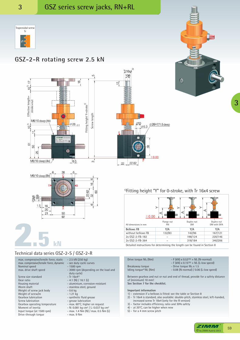
6890 Lustenau/Austriahttp://www.zimm.at
Type: GSZ-2-RNstatic: 2,5 kN ratio: i=4:1n, mom: 1500 rpm n, max: 3000 rpmserial-no: L-Z01-0013568
59© by ZIMM Austria 2013
GSZ-2-R rotating screw 2.5 kN
GSZ series screw jacks, RN+RL
max. compressive/tensile force, static - 2.5 kN (250 kg)max. compressive/tensile force, dynamic - see duty cycle curvesNominal speed - 1500 rpmmax. drive shaft speed - 3000 rpm (depending on the load and
duty cycle)Screw size standard - Tr 16x42)
Gear ratio - 4:1 (N) / 16:1 (L)Housing material - aluminium, corrosion-resistantWorm shaft - stainless steel, groundWeight of screw jack body - 0.6 kgWeight of screw/m - 1.21 kgGearbox lubrication - synthetic fluid greaseScrew lubrication - grease lubricationGearbox operating temperature - max. 60°C, higher on requestMoment of inertia - N: 0.081 kg cm2 / L: 0.037 kg cm2
Input torque (at 1500 rpm) - max. 1.4 Nm (N) / max. 0.5 Nm (L)Drive-through torque - max. 9 Nm
Drive torque MG (Nm) - F (kN) x 0.523)5) + ML (N-normal) - F (kN) x 0.153)5) + ML (L-low speed)Breakaway torque - Drive torque MG x 1.5Idling torque4) ML (Nm) - 0.08 (N-normal) / 0.06 (L-low speed)
Between gearbox and nut or nut and end of thread, provide for a safety distanceof (minimum) 10 mm!See Section 7 for the checklist.
Important information1) - extension if a bellows is fitted: see the table or Section 82) - Tr 16x4 is standard, also available: double-pitch, stainless steel, left-handed,
increased screw Tr 18x4 (only for the R version)3) - factor includes efficiency, ratio and 30% safety4) - at 20°C, can be higher when new5) - for a 4 mm screw pitch
Technical data series GSZ-2-S / GSZ-2-R
Bellows FB Y/A Y/A Y/Awithout bellows FB 132/83 142/96 167/1212x GSZ-2-FB-182 – 198/124 220/1462x GSZ-2-FB-364 – 318/184 340/206
Detailed instructions for determining the length can be found in Section 8
1)Fitting height “Y” for 0-stroke, with Tr 16x4 screw
Flange nutFM
Duplex nutDM
Duplex nutDM with SIFAAll dimensions in mm
Trapezoidal screwTr
3
3
kN
Scre
wle
ngthEffe
ctiv
e le
ngth
=st
roke
+nut
Fitt
ing
heig
ht Y
+str
oke1)
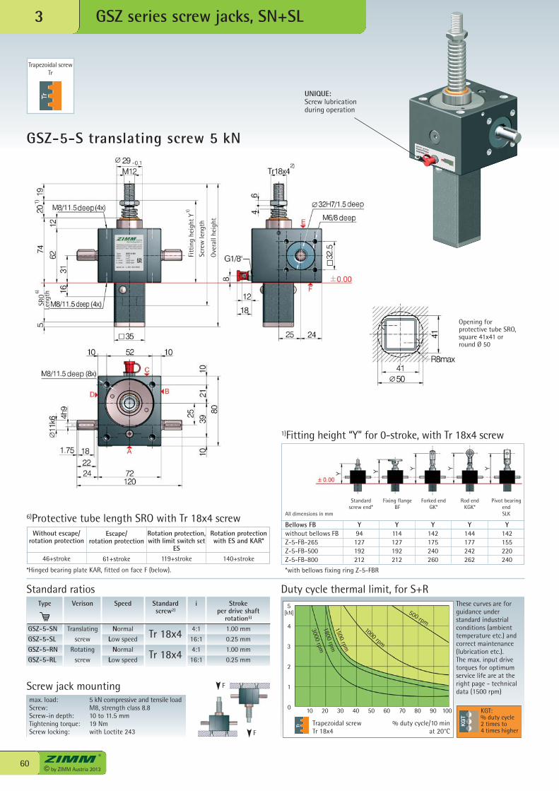
ZIMM Maschinenelemente GmbH + Co KGMillennium Park 3 · 6890 Lustenau/Austria0043 (0) 5577 / 806-0 · http://www.zimm.at
Type: GSZ-5-SNstatic: 5 kNratio: i=4:1n, nom: 1500 rpmn, max: 3000 rpm
serial-no: L-Z01-0013569
© by ZIMM Austria 201360
[kN]
0 10 20 30 40 50 60 70 80 90 100
5
4
3
2
1
GSZ-5-S translating screw 5 kN
GSZ series screw jacks, SN+SL3
max. load: 5 kN compressive and tensile loadScrew: M8, strength class 8.8Screw-in depth: 10 to 11.5 mmTightening torque: 19 NmScrew locking: with Loctite 243
Screw jack mounting
*Hinged bearing plate KAR, fitted on face F (below).
6)Protective tube length SRO with Tr 18x4 screw
Trapezoidal screwTr 18x4
Duty cycle thermal limit, for S+RThese curves are forguidance understandard industrialconditions (ambienttemperature etc.) andcorrect maintenance(lubrication etc.). The max. input drivetorques for optimumservice life are at theright page - technicaldata (1500 rpm)
% duty cycle/10 min at 20°C
Type
GSZ-5-SNGSZ-5-SLGSZ-5-RNGSZ-5-RL
Speed
Normal
Low speed
Normal
Low speed
i
4:1
16:1
4:1
16:1
Stroke per drive shaft
rotation5)
1.00 mm
0.25 mm
1.00 mm
0.25 mm
Verison
Translating
screw
Rotating
screw
Standardscrew2)
Tr 18x4
Tr 18x4
F
Bellows FB Y Y Y Y Ywithout bellows FB 94 114 142 144 142Z-5-FB-265 127 127 175 177 155Z-5-FB-500 192 192 240 242 220Z-5-FB-800 212 212 260 262 240
*with bellows fixing ring Z-5-FBR
Standard ratios
1)Fitting height “Y” for 0-stroke, with Tr 18x4 screw
F
KGT:% duty cycle2 times to4 times higher
500 rpm1000 rpm
1500 rpm
1800 rpm
3000 rpm
Rotation protection,with limit switch set
ES119+stroke
Escape/rotation protection
61+stroke
Without escape/rotation protection
46+stroke
Rotation protectionwith ES and KAR*
140+stroke
Trapezoidal screwTr
Opening forprotective tube SRO,square 41x41 orround Ø 50
All dimensions in mm
Standard screw end*
Fixing flangeBF
Forked endGK*
Rod endKGK*
Pivot bearingendSLK
UNIQUE:Screw lubricationduring operation
Fitt
ing
heig
ht Y
Scre
wle
ngth
Ove
rall
heig
ht
SRO
Leng
th6)
1)
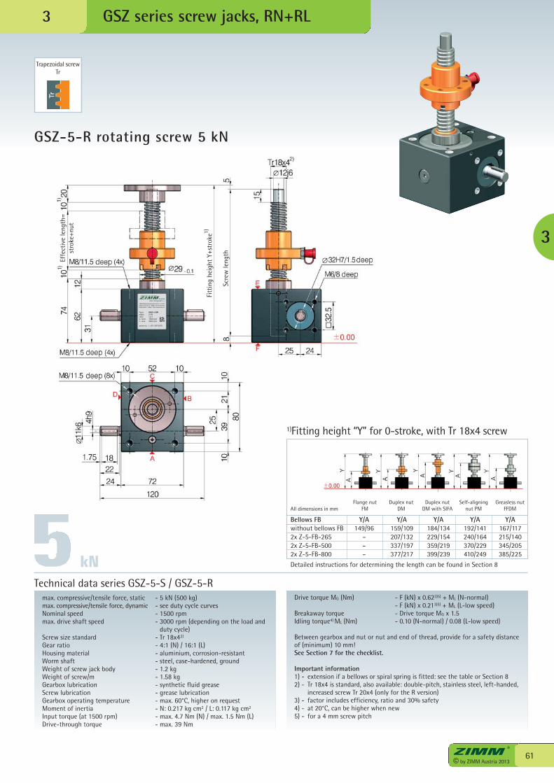
ZIMM Maschinenelemente GmbH + Co KGMillennium Park 3 · 6890 Lustenau/Austria0043 (0) 5577 / 806-0 · http://www.zimm.at
Type: GSZ-5-RNstatic: 5 kNratio: i=4:1n, nom: 1500 rpmn, max: 3000 rpm
serial-no: L-Z01-0013570
61© by ZIMM Austria 2013
GSZ-5-R rotating screw 5 kN
GSZ series screw jacks, RN+RL
max. compressive/tensile force, static - 5 kN (500 kg)max. compressive/tensile force, dynamic - see duty cycle curvesNominal speed - 1500 rpmmax. drive shaft speed - 3000 rpm (depending on the load and
duty cycle)Screw size standard - Tr 18x42)
Gear ratio - 4:1 (N) / 16:1 (L)Housing material - aluminium, corrosion-resistantWorm shaft - steel, case-hardened, groundWeight of screw jack body - 1.2 kgWeight of screw/m - 1.58 kgGearbox lubrication - synthetic fluid greaseScrew lubrication - grease lubricationGearbox operating temperature - max. 60°C, higher on requestMoment of inertia - N: 0.217 kg cm2 / L: 0.117 kg cm2
Input torque (at 1500 rpm) - max. 4.7 Nm (N) / max. 1.5 Nm (L)Drive-through torque - max. 39 Nm
Drive torque MG (Nm) - F (kN) x 0.623)5) + ML (N-normal) - F (kN) x 0.213)5) + ML (L-low speed)Breakaway torque - Drive torque MG x 1.5Idling torque4) ML (Nm) - 0.10 (N-normal) / 0.08 (L-low speed)
Between gearbox and nut or nut and end of thread, provide for a safety distanceof (minimum) 10 mm!See Section 7 for the checklist.
Important information1) - extension if a bellows or spiral spring is fitted: see the table or Section 82) - Tr 18x4 is standard, also available: double-pitch, stainless steel, left-handed,
increased screw Tr 20x4 (only for the R version)3) - factor includes efficiency, ratio and 30% safety4) - at 20°C, can be higher when new5) - for a 4 mm screw pitch
Technical data series GSZ-5-S / GSZ-5-R
Bellows FB Y/A Y/A Y/A Y/A Y/Awithout bellows FB 149/96 159/109 184/134 192/141 167/1172x Z-5-FB-265 – 207/132 229/154 240/164 215/1402x Z-5-FB-500 – 337/197 359/219 370/229 345/2052x Z-5-FB-800 – 377/217 399/239 410/249 385/225
Detailed instructions for determining the length can be found in Section 8
1)Fitting height “Y” for 0-stroke, with Tr 18x4 screw
Flange nutFM
Duplex nutDM
Duplex nutDM with SIFAAll dimensions in mm
Trapezoidal screwTr
3
Self-aligningnut PM
Greasless nutFFDM
kN
3Sc
rew
leng
th
Effe
ctiv
e le
ngth
=st
roke
+nut
Fitt
ing
heig
ht Y
+str
oke1)
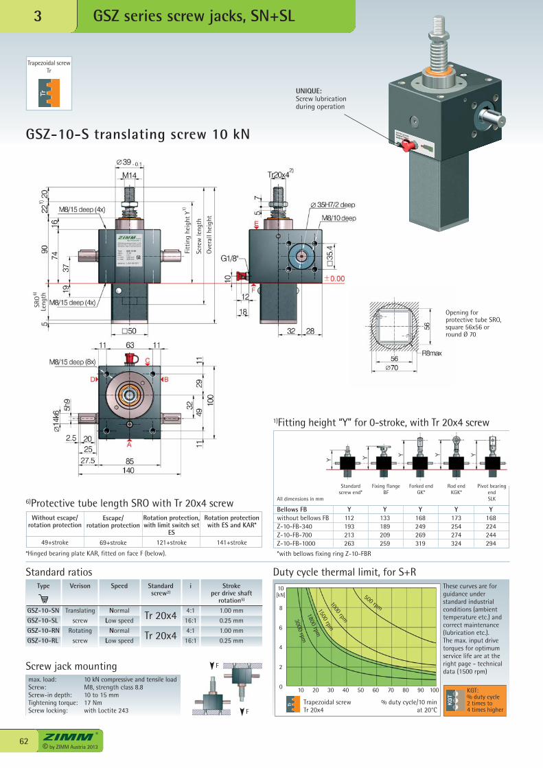
ZIMM Maschinenelemente GmbH + Co KGMillennium Park 3 · 6890 Lustenau/Austria0043 (0) 5577 / 806-0 · http://www.zimm.at
Type: GSZ-10-SNstatic: 10 kNratio: i=4:1n, nom: 1500 rpmn, max: 3000 rpm
serial-no: L-Z01-0013571
© by ZIMM Austria 201362
[kN]
0 10 20 30 40 50 60 70 80 90 100
10
8
6
4
2
GSZ-10-S translating screw 10 kN
GSZ series screw jacks, SN+SL3
max. load: 10 kN compressive and tensile loadScrew: M8, strength class 8.8Screw-in depth: 10 to 15 mmTightening torque: 17 NmScrew locking: with Loctite 243
Screw jack mounting
*Hinged bearing plate KAR, fitted on face F (below).
6)Protective tube length SRO with Tr 20x4 screw
Trapezoidal screwTr 20x4
Duty cycle thermal limit, for S+RThese curves are forguidance understandard industrialconditions (ambienttemperature etc.) andcorrect maintenance(lubrication etc.). The max. input drivetorques for optimumservice life are at theright page - technicaldata (1500 rpm)
% duty cycle/10 min at 20°C
Type
GSZ-10-SNGSZ-10-SLGSZ-10-RNGSZ-10-RL
Speed
Normal
Low speed
Normal
Low speed
i
4:1
16:1
4:1
16:1
Stroke per drive shaft
rotation5)
1.00 mm
0.25 mm
1.00 mm
0.25 mm
Verison
Translating
screw
Rotating
screw
Standardscrew2)
Tr 20x4
Tr 20x4
F
Standard ratios
F
KGT:% duty cycle2 times to4 times higher
Opening forprotective tube SRO,square 56x56 orround Ø 70
500 rpm
1000 rpm
1500 rpm
1800 rpm
3000 rpm
Rotation protection,with limit switch set
ES121+stroke
Escape/rotation protection
69+stroke
Without escape/rotation protection
49+stroke
Rotation protectionwith ES and KAR*
141+stroke
Trapezoidal screwTr
Bellows FB Y Y Y Y Ywithout bellows FB 112 133 168 173 168Z-10-FB-340 193 189 249 254 224Z-10-FB-700 213 209 269 274 244Z-10-FB-1000 263 259 319 324 294
*with bellows fixing ring Z-10-FBR
1)Fitting height “Y” for 0-stroke, with Tr 20x4 screw
All dimensions in mm
Standard screw end*
Fixing flangeBF
Forked endGK*
Rod endKGK*
Pivot bearingendSLK
UNIQUE:Screw lubricationduring operation
Fitt
ing
heig
ht Y
Scre
wle
ngth
Ove
rall
heig
ht
SRO
Leng
th6)
1)
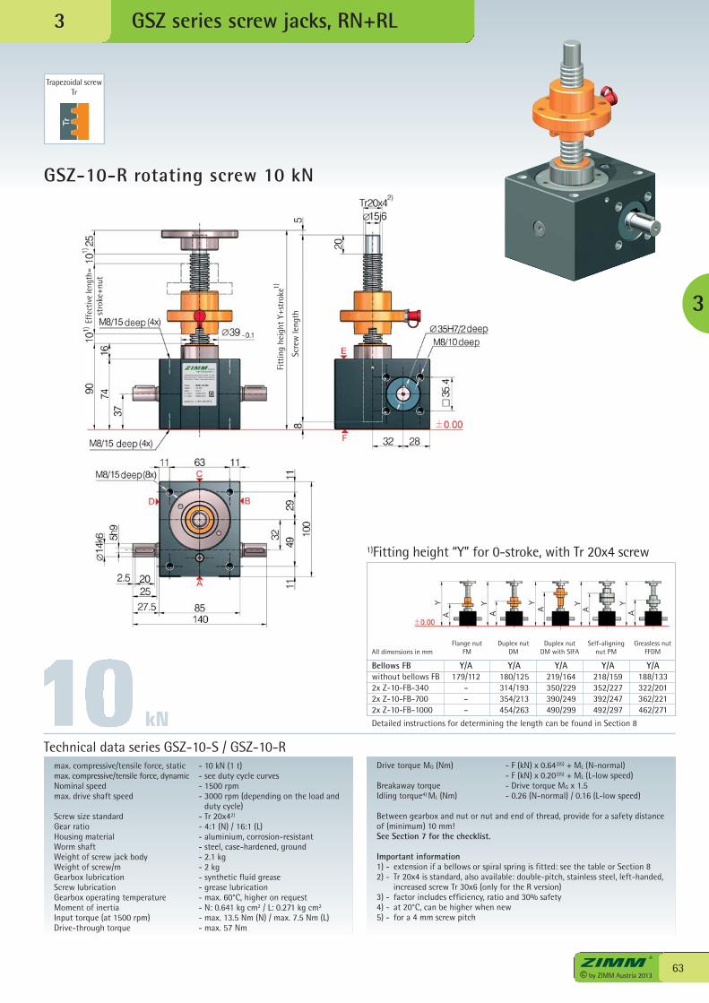
ZIMM Maschinenelemente GmbH + Co KGMillennium Park 3 · 6890 Lustenau/Austria0043 (0) 5577 / 806-0 · http://www.zimm.at
Type: GSZ-10-RNstatic: 10 kNratio: i=4:1n, nom: 1500 rpmn, max: 3000 rpm
serial-no: L-Z01-0013572
63© by ZIMM Austria 2013
GSZ-10-R rotating screw 10 kN
GSZ series screw jacks, RN+RL
max. compressive/tensile force, static - 10 kN (1 t)max. compressive/tensile force, dynamic - see duty cycle curvesNominal speed - 1500 rpmmax. drive shaft speed - 3000 rpm (depending on the load and
duty cycle)Screw size standard - Tr 20x42)
Gear ratio - 4:1 (N) / 16:1 (L)Housing material - aluminium, corrosion-resistantWorm shaft - steel, case-hardened, groundWeight of screw jack body - 2.1 kgWeight of screw/m - 2 kgGearbox lubrication - synthetic fluid greaseScrew lubrication - grease lubricationGearbox operating temperature - max. 60°C, higher on requestMoment of inertia - N: 0.641 kg cm2 / L: 0.271 kg cm2
Input torque (at 1500 rpm) - max. 13.5 Nm (N) / max. 7.5 Nm (L)Drive-through torque - max. 57 Nm
Drive torque MG (Nm) - F (kN) x 0.643)5) + ML (N-normal) - F (kN) x 0.203)5) + ML (L-low speed)Breakaway torque - Drive torque MG x 1.5Idling torque4) ML (Nm) - 0.26 (N-normal) / 0.16 (L-low speed)
Between gearbox and nut or nut and end of thread, provide for a safety distanceof (minimum) 10 mm!See Section 7 for the checklist.
Important information1) - extension if a bellows or spiral spring is fitted: see the table or Section 82) - Tr 20x4 is standard, also available: double-pitch, stainless steel, left-handed,
increased screw Tr 30x6 (only for the R version)3) - factor includes efficiency, ratio and 30% safety4) - at 20°C, can be higher when new5) - for a 4 mm screw pitch
Technical data series GSZ-10-S / GSZ-10-R
Trapezoidal screwTr
3
3
Bellows FB Y/A Y/A Y/A Y/A Y/Awithout bellows FB 179/112 180/125 219/164 218/159 188/1332x Z-10-FB-340 – 314/193 350/229 352/227 322/2012x Z-10-FB-700 – 354/213 390/249 392/247 362/2212x Z-10-FB-1000 – 454/263 490/299 492/297 462/271
Detailed instructions for determining the length can be found in Section 8
1)Fitting height “Y” for 0-stroke, with Tr 20x4 screw
Flange nutFM
Duplex nutDM
Duplex nutDM with SIFAAll dimensions in mm
Self-aligningnut PM
Greasless nutFFDM
kN
Scre
wle
ngth
Effe
ctiv
e le
ngth
=st
roke
+nut
Fitt
ing
heig
ht Y
+str
oke1)
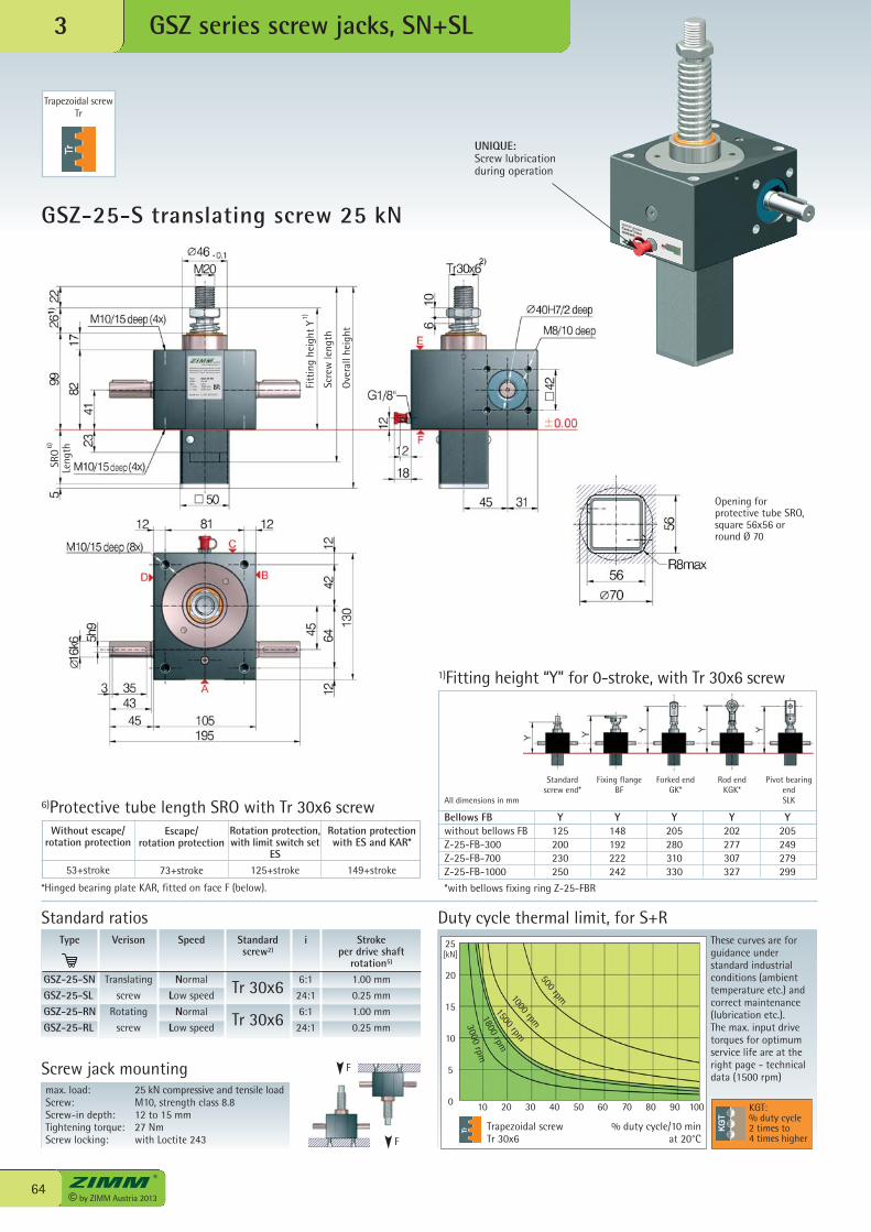
ZIMM Maschinenelemente GmbH + Co KGMillennium Park 3 · 6890 Lustenau/Austria0043 (0) 5577 / 806-0 · http://www.zimm.at
Type: GSZ-25-SNstatic: 25 kNratio: i=6:1n, nom: 1500 rpmn, max: 3000 rpm
serial-no: L-Z01-0013573
© by ZIMM Austria 201364
[kN]
0 10 20 30 40 50 60 70 80 90 100
25
20
15
10
5
GSZ-25-S translating screw 25 kN
GSZ series screw jacks, SN+SL3
max. load: 25 kN compressive and tensile loadScrew: M10, strength class 8.8Screw-in depth: 12 to 15 mmTightening torque: 27 NmScrew locking: with Loctite 243
Screw jack mounting
*Hinged bearing plate KAR, fitted on face F (below).
6)Protective tube length SRO with Tr 30x6 screw
Trapezoidal screwTr 30x6
Duty cycle thermal limit, for S+RThese curves are forguidance understandard industrialconditions (ambienttemperature etc.) andcorrect maintenance(lubrication etc.). The max. input drivetorques for optimumservice life are at theright page - technicaldata (1500 rpm)
% duty cycle/10 min at 20°C
Type
GSZ-25-SNGSZ-25-SLGSZ-25-RNGSZ-25-RL
Speed
Normal
Low speed
Normal
Low speed
i
6:1
24:1
6:1
24:1
Stroke per drive shaft
rotation5)
1.00 mm
0.25 mm
1.00 mm
0.25 mm
Verison
Translating
screw
Rotating
screw
Standardscrew2)
Tr 30x6
Tr 30x6
F
Standard ratios
F
KGT:% duty cycle2 times to4 times higher
Opening forprotective tube SRO,square 56x56 orround Ø 70
500 rpm1000 rpm
1500 rpm
1800 rpm
3000 rpm
Rotation protection,with limit switch set
ES125+stroke
Escape/rotation protection
73+stroke
Without escape/rotation protection
53+stroke
Rotation protectionwith ES and KAR*
149+stroke
Trapezoidal screwTr
Bellows FB Y Y Y Y Ywithout bellows FB 125 148 205 202 205Z-25-FB-300 200 192 280 277 249Z-25-FB-700 230 222 310 307 279Z-25-FB-1000 250 242 330 327 299
*with bellows fixing ring Z-25-FBR
1)Fitting height “Y” for 0-stroke, with Tr 30x6 screw
All dimensions in mm
Standard screw end*
Fixing flangeBF
Forked endGK*
Rod endKGK*
Pivot bearingendSLK
UNIQUE:Screw lubricationduring operation
Fitt
ing
heig
ht Y
Scre
wle
ngth
Ove
rall
heig
ht
SRO
Leng
th6)
1)
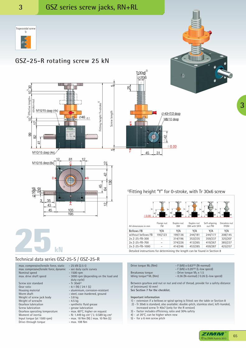
ZIMM Maschinenelemente GmbH + Co KGMillennium Park 3 · 6890 Lustenau/Austria0043 (0) 5577 / 806-0 · http://www.zimm.at
Type: GSZ-25-RNstatic: 25 kNratio: i=6:1n, nom: 1500 rpmn, max: 3000 rpm
serial-no: L-Z01-0013574
65© by ZIMM Austria 2013
GSZ-25-R rotating screw 25 kN
GSZ series screw jacks, RN+RL
max. compressive/tensile force, static - 25 kN (2.5 t)max. compressive/tensile force, dynamic - see duty cycle curvesNominal speed - 1500 rpmmax. drive shaft speed - 3000 rpm (depending on the load and
duty cycle)Screw size standard - Tr 30x62)
Gear ratio - 6:1 (N) / 24:1 (L)Housing material - aluminium, corrosion-resistantWorm shaft - steel, case-hardened, groundWeight of screw jack body - 3.8 kgWeight of screw/m - 4.5 kgGearbox lubrication - synthetic fluid greaseScrew lubrication - grease lubricationGearbox operating temperature - max. 60°C, higher on requestMoment of inertia - N: 1.449 kg cm2 / L: 0.589 kg cm2
Input torque (at 1500 rpm) - max. 18 Nm (N) / max. 10 Nm (L)Drive-through torque - max. 108 Nm
Drive torque MG (Nm) - F (kN) x 0.633)5) (N-normal) - F (kN) x 0.203)5) (L-low speed)Breakaway torque - Drive torque MG x 1.5Idling torque4) ML (Nm) - 0.36 (N-normal) / 0.26 (L-low speed)
Between gearbox and nut or nut and end of thread, provide for a safety distanceof (minimum) 10 mm!See Section 7 for the checklist.
Important information1) - extension if a bellows or spiral spring is fitted: see the table or Section 82) - Tr 30x6 is standard, also available: double-pitch, stainless steel, left-handed,
increased screw Tr 40x7 (only for the R version)3) - factor includes efficiency, ratio and 30% safety4) - at 20°C, can be higher when new5) - for a 6 mm screw pitch
Technical data series GSZ-25-S / GSZ-25-R
Trapezoidal screwTr
3
3
kN
Bellows FB Y/A Y/A Y/A Y/A Y/Awithout bellows FB 195/123 199/136 244/181 244/177 208/1452x Z-25-FB-300 – 314/196 353/235 359/237 325/2072x Z-25-FB-700 – 374/226 413/265 419/267 385/2372x Z-25-FB-1000 – 414/246 453/285 459/287 425/257
Detailed instructions for determining the length can be found in Section 8
1)Fitting height “Y” for 0-stroke, with Tr 30x6 screw
Flange nutFM
Duplex nutDM
Duplex nutDM with SIFAAll dimensions in mm
Self-aligningnut PM
Greasless nutFFDM
Scre
wle
ngth
Effe
ctiv
e le
ngth
=st
roke
+nut
Fitt
ing
heig
ht Y
+str
oke1)
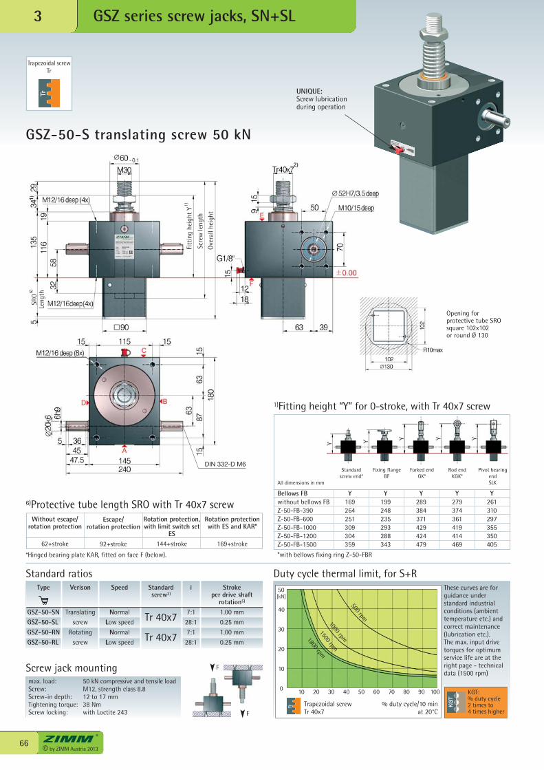
ZIMM Maschinenelemente GmbH + Co KGMillennium Park 3 · 6890 Lustenau/Austria0043 (0) 5577 / 806-0 · http://www.zimm.at
Type: GSZ-50-SNstatic: 50 kNratio: i=7:1n, nom: 1500 rpmn, max: 1800 rpm
serial-no: L-Z01-0013575
© by ZIMM Austria 201366
[kN]
0 10 20 30 40 50 60 70 80 90 100
50
40
30
20
10
GSZ-50-S translating screw 50 kN
GSZ series screw jacks, SN+SL3
max. load: 50 kN compressive and tensile loadScrew: M12, strength class 8.8Screw-in depth: 12 to 17 mmTightening torque: 38 NmScrew locking: with Loctite 243
Screw jack mounting
*Hinged bearing plate KAR, fitted on face F (below).
6)Protective tube length SRO with Tr 40x7 screw
Trapezoidal screwTr 40x7
Duty cycle thermal limit, for S+RThese curves are forguidance understandard industrialconditions (ambienttemperature etc.) andcorrect maintenance(lubrication etc.). The max. input drivetorques for optimumservice life are at theright page - technicaldata (1500 rpm)
% duty cycle/10 min at 20°C
Type
GSZ-50-SNGSZ-50-SLGSZ-50-RNGSZ-50-RL
Speed
Normal
Low speed
Normal
Low speed
i
7:1
28:1
7:1
28:1
Stroke per drive shaft
rotation5)
1.00 mm
0.25 mm
1.00 mm
0.25 mm
Verison
Translating
screw
Rotating
screw
Standardscrew2)
Tr 40x7
Tr 40x7
F
Standard ratios
F
KGT:% duty cycle2 times to4 times higher
Opening for protective tube SRO square 102x102or round Ø 130
500 rpm
1000 rpm
1500 rpm
1800 rpm
Rotation protection,with limit switch set
ES144+stroke
Escape/rotation protection
92+stroke
Without escape/rotation protection
62+stroke
Rotation protectionwith ES and KAR*
169+stroke
Trapezoidal screwTr
Bellows FB Y Y Y Y Ywithout bellows FB 169 199 289 279 261Z-50-FB-390 264 248 384 374 310Z-50-FB-600 251 235 371 361 297Z-50-FB-1000 309 293 429 419 355Z-50-FB-1200 304 288 424 414 350Z-50-FB-1500 359 343 479 469 405
*with bellows fixing ring Z-50-FBR
1)Fitting height “Y” for 0-stroke, with Tr 40x7 screw
All dimensions in mm
Standard screw end*
Fixing flangeBF
Forked endGK*
Rod endKGK*
Pivot bearingendSLK
UNIQUE:Screw lubricationduring operation
Fitt
ing
heig
ht Y
Scre
wle
ngth
Ove
rall
heig
ht
SRO
Leng
th6)
1)
DIN 332-D M6
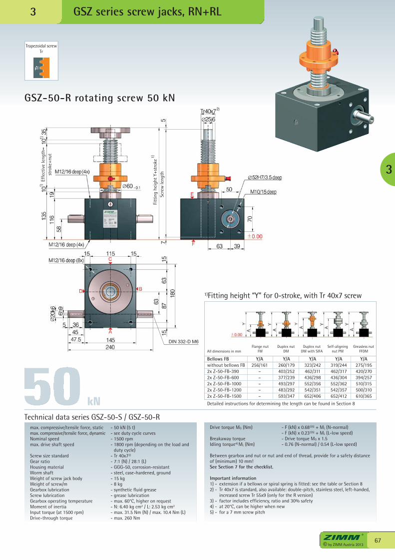
ZIMM Maschinenelemente GmbH + Co KGMillennium Park 3 · 6890 Lustenau/Austria0043 (0) 5577 / 806-0 · http://www.zimm.at
Type: GSZ-50-RNstatic: 50 kNratio: i=7:1n, nom: 1500 rpmn, max: 1800 rpm
serial-no: L-Z01-0013576
67© by ZIMM Austria 2013
GSZ-50-R rotating screw 50 kN
GSZ series screw jacks, RN+RL
max. compressive/tensile force, static - 50 kN (5 t)max. compressive/tensile force, dynamic - see duty cycle curvesNominal speed - 1500 rpmmax. drive shaft speed - 1800 rpm (depending on the load and
duty cycle)Screw size standard - Tr 40x72)
Gear ratio - 7:1 (N) / 28:1 (L)Housing material - GGG-50, corrosion-resistantWorm shaft - steel, case-hardened, groundWeight of screw jack body - 15 kgWeight of screw/m - 8 kgGearbox lubrication - synthetic fluid greaseScrew lubrication - grease lubricationGearbox operating temperature - max. 60°C, higher on requestMoment of inertia - N: 6.40 kg cm2 / L: 2.53 kg cm2
Input torque (at 1500 rpm) - max. 31.5 Nm (N) / max. 10.4 Nm (L)Drive-through torque - max. 260 Nm
Drive torque MG (Nm) - F (kN) x 0.683)5) + ML (N-normal) - F (kN) x 0.233)5) + ML (L-low speed)Breakaway torque - Drive torque MG x 1.5Idling torque4) ML (Nm) - 0.76 (N-normal) / 0.54 (L-low speed)
Between gearbox and nut or nut and end of thread, provide for a safety distanceof (minimum) 10 mm!See Section 7 for the checklist.
Important information1) - extension if a bellows or spiral spring is fitted: see the table or Section 82) - Tr 40x7 is standard, also available: double-pitch, stainless steel, left-handed,
increased screw Tr 55x9 (only for the R version)3) - factor includes efficiency, ratio and 30% safety4) - at 20°C, can be higher when new5) - for a 7 mm screw pitch
Technical data series GSZ-50-S / GSZ-50-R
Trapezoidal screwTr
3
3
kN
Bellows FB Y/A Y/A Y/A Y/A Y/Awithout bellows FB 256/161 260/179 323/242 319/244 275/1952x Z-50-FB-390 – 403/252 462/311 462/317 420/2702x Z-50-FB-600 – 377/239 436/298 436/304 394/2572x Z-50-FB-1000 – 493/297 552/356 552/362 510/3152x Z-50-FB-1200 – 483/292 542/351 542/357 500/3102x Z-50-FB-1500 – 593/347 652/406 652/412 610/365
Detailed instructions for determining the length can be found in Section 8
1)Fitting height “Y” for 0-stroke, with Tr 40x7 screw
Flange nutFM
Duplex nutDM
Duplex nutDM with SIFAAll dimensions in mm
Self-aligningnut PM
Greasless nutFFDM
Scre
wle
ngth
Effe
ctiv
e le
ngth
=st
roke
+nut
Fitt
ing
heig
ht Y
+str
oke1)
DIN 332-D M6
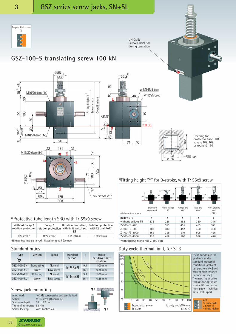
ZIMM Maschinenelemente GmbH + Co KGMillennium Park 3 · 6890 Lustenau/Austria0043 (0) 5577 / 806-0 · http://www.zimm.at
Type: GSZ-100-SNstatic: 100 kNratio: i=9:1n, nom: 1500 rpmn, max: 1800 rpm
serial-no: L-Z01-0013577
DIN 332-D M10
© by ZIMM Austria 201368
[kN]
0 10 20 30 40 50 60 70 80 90 100
100
80
60
40
20
GSZ-100-S translating screw 100 kN
GSZ series screw jacks, SN+SL3
max. load: 100 kN compressive and tensile loadScrew: M16, strength class 8.8Screw-in depth: 16 to 22 mmTightening torque: 82 NmScrew locking: with Loctite 243
Screw jack mounting
*Hinged bearing plate KAR, fitted on face F (below)
6)Protective tube length SRO with Tr 55x9 screw
Trapezoidal screwTr 55x9
Duty cycle thermal limit, for S+RThese curves are forguidance understandard industrialconditions (ambienttemperature etc.) andcorrect maintenance(lubrication etc.). The max. input drivetorques for optimumservice life are at theright page - technicaldata (1500 rpm)
% duty cycle/10 min at 20°C
Type
GSZ-100-SNGSZ-100-SLGSZ-100-RNGSZ-100-RL
Speed
Normal
Low speed
Normal
Low speed
i
9:1
36:1
9:1
36:1
Stroke per drive shaft
rotation5)
1.00 mm
0.25 mm
1.00 mm
0.25 mm
Verison
Translating
screw
Rotating
screw
Standardscrew2)
Tr 55x9
Tr 55x9
F
Standard ratios
F
KGT:% duty cycle2 times to4 times higher
Opening for protective tube SRO square 102x102or round Ø 130
500 rpm1000 rpm
1500 rpm
1800 rpm
Rotation protection,with limit switch set
ES144+stroke
Escape/rotation protection
112+stroke
Without escape/rotation protection
82+stroke
Rotation protectionwith ES and KAR*
189+stroke
Trapezoidal screwTr
Bellows FB Y Y Y Y Ywithout bellows FB 238 288 382 380 346Z-100-FB-285 311 313 455 453 371Z-100-FB-600 308 310 452 450 368Z-100-FB-1000 366 368 510 508 426Z-100-FB-1500 416 418 560 558 476
*with bellows fixing ring Z-100-FBR
1)Fitting height “Y” for 0-stroke, with Tr 55x9 screw
All dimensions in mm
Standard screw end*
Fixing flangeBF
Forked endGK*
Rod endKGK*
Pivot bearingendSLK
UNIQUE:Screw lubricationduring operation
Fitt
ing
heig
ht Y
Scre
wle
ngth
Ove
rall
heig
ht
SRO
Leng
th6)
1)
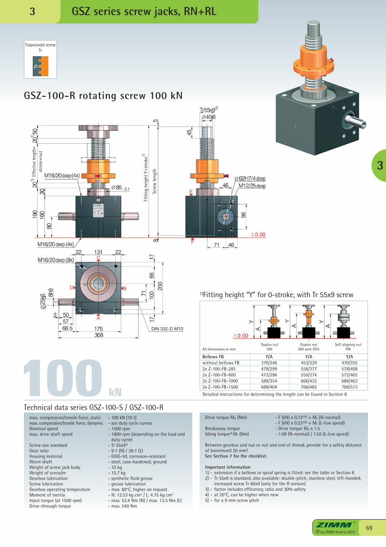
ZIMM Maschinenelemente GmbH + Co KGMillennium Park 3 · 6890 Lustenau/Austria0043 (0) 5577 / 806-0 · http://www.zimm.at
Type: GSZ-100-RNstatic: 100 kNratio: i=9:1n, nom: 1500 rpmn, max: 1800 rpm
serial-no: L-Z01-0013578
DIN 332-D M10
69© by ZIMM Austria 2013
GSZ-100-R rotating screw 100 kN
GSZ series screw jacks, RN+RL
max. compressive/tensile force, static - 100 kN (10 t)max. compressive/tensile force, dynamic - see duty cycle curvesNominal speed - 1500 rpmmax. drive shaft speed - 1800 rpm (depending on the load and
duty cycle)Screw size standard - Tr 55x92)
Gear ratio - 9:1 (N) / 36:1 (L)Housing material - GGG-50, corrosion-resistantWorm shaft - steel, case-hardened, groundWeight of screw jack body - 33 kgWeight of screw/m - 15.7 kgGearbox lubrication - synthetic fluid greaseScrew lubrication - grease lubricationGearbox operating temperature - max. 60°C, higher on requestMoment of inertia - N: 12.53 kg cm2 / L: 4.75 kg cm2
Input torque (at 1500 rpm) - max. 53.4 Nm (N) / max. 13.5 Nm (L)Drive-through torque - max. 540 Nm
Drive torque MG (Nm) - F (kN) x 0.723)5) + ML (N-normal) - F (kN) x 0.233)5) + ML (L-low speed)Breakaway torque - Drive torque MG x 1.5Idling torque4) ML (Nm) - 1.68 (N-normal) / 1.02 (L-low speed)
Between gearbox and nut or nut and end of thread, provide for a safety distanceof (minimum) 20 mm!See Section 7 for the checklist.
Important information1) - extension if a bellows or spiral spring is fitted: see the table or Section 82) - Tr 55x9 is standard, also available: double-pitch, stainless steel, left-handed,
increased screw Tr 60x9 (only for the R version)3) - factor includes efficiency, ratio and 30% safety4) - at 20°C, can be higher when new5) - for a 9 mm screw pitch
Technical data series GSZ-100-S / GSZ-100-R
Trapezoidal screwTr
3
3
Bellows FB Y/A Y/A Y/Awithout bellows FB 370/246 453/329 470/3552x Z-100-FB-285 478/299 556/377 578/4082x Z-100-FB-600 472/296 550/374 572/4052x Z-100-FB-1000 588/354 666/432 688/4632x Z-100-FB-1500 688/404 766/482 788/513
Detailed instructions for determining the length can be found in Section 8
1)Fitting height “Y” for 0-stroke, with Tr 55x9 screw
Duplex nutDM
Duplex nutDM with SIFA
Self-aligning nutPMAll dimensions in mm
kN
Scre
wle
ngth
Effe
ctiv
e le
ngth
=st
roke
+nut
Fitt
ing
heig
ht Y
+str
oke1)
We have patents registered or pending for a range of functions and components.
PA
TENT
P E N D I NG
zum Patent
angemeldet
© by ZIMM Austria 201370
GSZ series screw jacks, KGT3
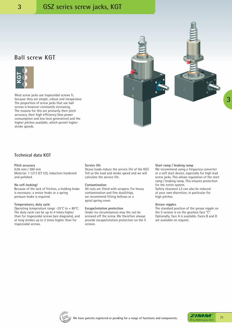
71© by ZIMM Austria 2013
GSZ series screw jacks, KGT
Ball screw KGT
3
3
Pitch accuracy0.05 mm / 300 mmMaterial: 1.1213 (Cf 53), induction hardenedand polished.
No self-locking!Because of the lack of friction, a holding brakeis necessary: a motor brake or a springpressure brake is required.
Temperatures, duty cycleOperating temperature range -25°C to + 80°C.The duty cycle can be up to 4 times higherthan for trapezoidal screws (see diagrams), andat long strokes up to 2 times higher than fortrapezoidal screws.
Most screw jacks use trapezoidal screws Tr,because they are simple, robust and inexpensive.The proportion of screw jacks that use ballscrews is however constantly increasing.The reasons for this are primarily their pitchaccuracy, their high efficiency (less powerconsumption and less heat generation) and thehigher pitches available, which permit higherstroke speeds.
Service lifeHeavy loads reduce the service life of the KGT.Tell us the load and stroke speed and we willcalculate the service life.
ContaminationAll nuts are fitted with scrapers. For heavycontamination and fine dust/chips,we recommend fitting bellows or aspiral spring cover.
Escape/rotation protectionUnder no circumstances may the nut bescrewed off the screw. We therefore alwaysprovide escape/rotation protection on the Sversion.
Start ramp / braking rampWe recommend using a frequency converter or a soft start device, especially for high leadscrew jacks. This allows regulation of the startramp / braking ramp. This ensures protectionfor the entire system.Safety clearance L3 can also be reducedat your own discretion, in particular for high pitches.
Grease nipplesThe standard position of the grease nipple onthe S version is on the gearbox face “C”.Optionally, face A is available. Faces B and Dare available on request.
Technical data KGT
We have patents registered or pending for a range of functions and components.
PA
TENT
P E N D I NG
zum Patent
angemeldet
KG
T
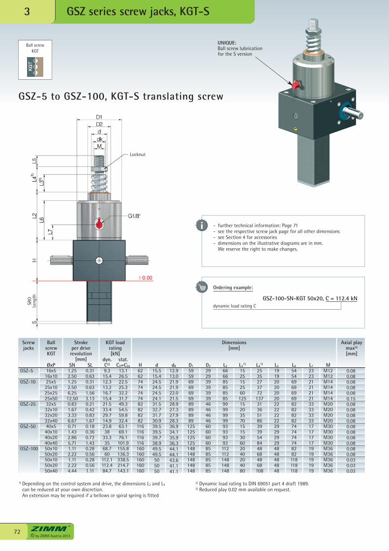
Ball screwKGT
© by ZIMM Austria 201372
GSZ-5 to GSZ-100, KGT-S translating screw
GSZ series screw jacks, KGT-S3
UNIQUE:Ball screw lubricationfor the S version
SL0.310.630.310.631.563.130.210.420.831.670.180.360.721.430.280.560.280.561.11
Screwjacks
BallscrewKGT
Stroke per driverevolution
[mm]SN
1.252.501.252.506.2512.500.831.673.336.670.711.432.865.711.112.221.112.224.44
ØxP16x516x1025x525x1025x2525x5032x532x1032x2032x4040x540x1040x2040x4050x1050x2050x1050x2050x40
stat.C0=C0a
13.126.522.525.332.231.749.354.559.832.463.169.176.1101.9155.8136.3338.5214.7143.1
KGT loadrating[kN]
dyn.C2)
9.315.412.313.216.715.421.533.429.714.923.838
33.335
68.760
112.1112.484.7
1) Depending on the control system and drive, the dimensions L3 and L4
can be reduced at your own discretion. An extension may be required if a bellows or spiral spring is fitted
2) Dynamic load rating to DIN 69051 part 4 draft 1989.5) Reduced play 0.02 mm available on request.
- further technical information: Page 71- see the respective screw jack page for all other dimensions - see Section 4 for accessories- dimensions on the illustrative diagrams are in mm. We reserve the right to make changes.
GSZ-5
GSZ-10
GSZ-25
GSZ-50
GSZ-100
Axial playmax5)
[mm]
Dimensions[mm]
H62627474747482828282116116116116160160160160160
d15.515.424.524.524.524.131.532.731.730.939.539.539.738.949.549.5505050
dK
12.913.021.921.922.021.528.927.327.928.336.934.135.936.344.144.143.641.141.1
D1
59596969696989898989125125125125148148148148148
D2
29293939393946464646606060608585858585
L2
6666858585859999999993939393112112148148148
L31)
152515256012515203570151530602040204080
L41)
2535273772137313651863939548448684868108
L5
19192020202022222222292929294848484848
L6
54546969696982828282747474748282118118118
L7
23232121212133333333171717171919191919
MM12M12M14M14M14M14M20M20M20M20M30M30M30M30M36M36M36M36M36
0.080.080.080.080.080.150.080.080.080.080.080.080.080.080.080.080.030.030.03
Ordering example:
GSZ-100-SN-KGT 50x20, C = 112.4 kNdynamic load rating CSR
OLe
ngth
Locknut
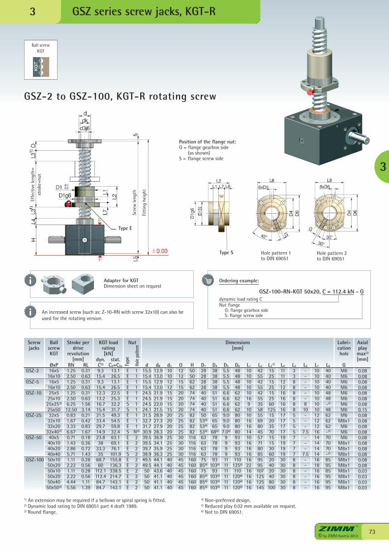
GSZ series screw jacks, KGT-R
Ball screwKGT
73© by ZIMM Austria 2013
GSZ-2 to GSZ-100, KGT-R rotating screw
3
3
Type S Hole pattern 1to DIN 69051
Screwjacks
BallscrewKGT
Stroke perdrive
revolution[mm]
RN1.252.501.252.501.252.506.2512.500.831.673.336.670.711.432.865.711.112.221.112.224.445.56
ØxP16x516x1016x516x1025x525x1025x253)
25x5032x532x1032x2032x403)
40x540x1040x2040x4050x1050x2050x1050x2050x4050x504)
GSZ-2
GSZ-5
GSZ-10
GSZ-25
GSZ-50
GSZ-100
stat.C0=C0a
13.126.513.126.522.525.332.231.749.354.559.832.463.169.176.1101.9155.8136.3338.5214.7143.1143.1
KGT loadrating[kN]
dyn.C2)
9.315.49.315.412.313.216.715.421.533.429.714.923.838
33.335
68.760
112.1112.484.784.7
RL0.310.630.310.630.310.631.563.140.210.420.831.670.180.360.721.430.280.560.280.561.111.39
EEEEEESSEEESEEESEEEEEE
Type
Hole
patte
rn
Nut
11111111111
N4)
2222222222
Axialplaymax5)
[mm]
Dimensions[mm]
d15.515.415.515.424.524.524.524.131.532.731.730.939.539.539.738.949.549.550505050
dK
12.913.012.913.021.921.922.021.528.927.327.928.336.934.135.936.344.144.143.641.141.141.1
d3
10101212151515152020202025252525404040404040
O12121515202020202525252530303030454545454545
H505062627474747482828282116116116116160160160160160160
D1
282828284040404050536)
536)
536)
6363636375856)
75856)
856)
856)
D4
3838383851515151656565686)
7878787893
1036)
931036)
1036)
1036)
D5
5.55.55.55.56.66.66.66.69.09.09.07.06)
9999111111111111
D6
48484848626262628080808093939393110
1256)
1101206)
1206)
1206)
L1
1010101010169101016161410161616162216161616
L2
425542554255355855698045577180859595107125125145
L31)
1525152515256012515203570151530602040204080100
L4
11111212161616161717171719191919303030303030
L5
3388888855557777888888
L6
------810---
7.5---
7.5------
L7
10101010101010101212121614141414161816161616
L8
404040404848-3)
48626262-3)
707070-3)
859585959595
GM6M6M6M6M6M6M6M6M6
M8x1M6M6M6
M8x1M8x1M8x1M8x1M8x1M8x1M8x1M8x1M8x1
Lubri-cationhole
0.080.080.080.080.080.080.080.150.080.080.080.080.080.080.080.080.080.080.030.030.030.03
An increased screw (such as: Z-10-RN with screw 32x10) can also beused for the rotating version.
Hole pattern 2to DIN 69051
1) An extension may be required if a bellows or spiral spring is fitted.2) Dynamic load rating to DIN 69051 part 4 draft 1989.3) Round flange.
4) Non-preferred design.5) Reduced play 0.02 mm available on request.6) Not to DIN 69051.
Position of the flange nut:G = flange gearbox side (as shown)S = flange screw side
Ordering example:
GSZ-100-RN-KGT 50x20, C = 112.4 kN - Gdynamic load rating CNut flange G: flange gearbox side S: flange screw side
Adapter for KGTDimension sheet on request
Type E
Effe
ctiv
e le
ngth
=st
roke
+nut
Scre
wle
ngth
Fitt
ing
heig
ht
© by ZIMM Austria 201374 We have patents registered or pending for a range of functions and components.
PA
TENT
P E N D I NG
zum Patent
angemeldet
GSZ series screw jacks, SIFA3
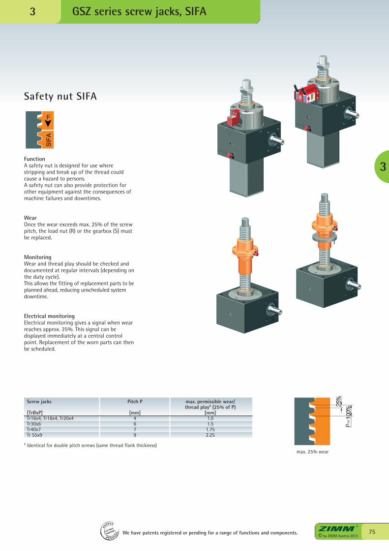
75© by ZIMM Austria 2013
Safety nut SIFA
GSZ series screw jacks, SIFA
3
3
FunctionA safety nut is designed for use wherestripping and break up of the thread couldcause a hazard to persons.A safety nut can also provide protection forother equipment against the consequences ofmachine failures and downtimes.
WearOnce the wear exceeds max. 25% of the screwpitch, the load nut (R) or the gearbox (S) mustbe replaced.
MonitoringWear and thread play should be checked anddocumented at regular intervals (depending onthe duty cycle).This allows the fitting of replacement parts to beplanned ahead, reducing unscheduled systemdowntime.
Electrical monitoringElectrical monitoring gives a signal when wearreaches approx. 25%. This signal can bedisplayed immediately at a central controlpoint. Replacement of the worn parts can thenbe scheduled.
Screw jacks Pitch P max. permissible wear/ thread play* (25% of P)[TrØxP] [mm] [mm]Tr16x4, Tr18x4, Tr20x4 4 1.0Tr30x6 6 1.5Tr40x7 7 1.75Tr 55x9 9 2.25
* Identical for double pitch screws (same thread flank thickness)max. 25% wear
We have patents registered or pending for a range of functions and components.
PA
TENT
P E N D I NG
zum Patent
angemeldet
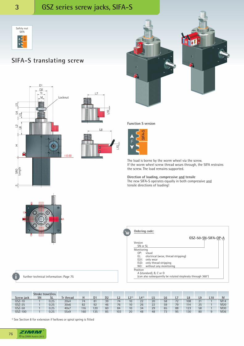
Locknut
© by ZIMM Austria 201376
GSZ series screw jacks, SIFA-S3
SIFA-S translating screw
Function S version
The load is borne by the worm wheel via the screw.If the worm wheel screw thread wears through, the SIFA restrainsthe screw. The load remains supported.
Direction of loading, compressive and tensileThe new SIFA-S operates equally in both compressive andtensile directions of loading!
further technical information: Page 75
Ordering code:
GSZ-50-SN-SIFA-OP-AVersion SN or SLMonitoring OP: visual EL: electrical (wear, thread stripping) ELV: only wear ELD: only thread stripping NO: without any monitoringPosition A (standard), B, C or D (can also subsequently be rotated steplessly through 360°)
Stroke travel/rev. Screw jack SN SL Tr thread H D1 D2 L2 L31) L41) L5 L6 L7 L8 L9 L10 M GSZ-10 1 0.25 20x4 74 81 39 74 10 22 20 58 72 108 21 1 M14 GSZ-25 1 0.25 30x6 82 92 46 76 10 26 22 59 79 114 25 1 M20 GSZ-50 1 0.25 40x7 116 120 60 84 10 34 29 65 88 123 58 1 M30 GSZ-100 1 0.25 55x9 160 135 85 103 20 48 48 73 95 130 80 9 M36
1) See Section 8 for extension if bellows or spiral spring is fitted
Safety nutSIFA
SRO
Leng
th
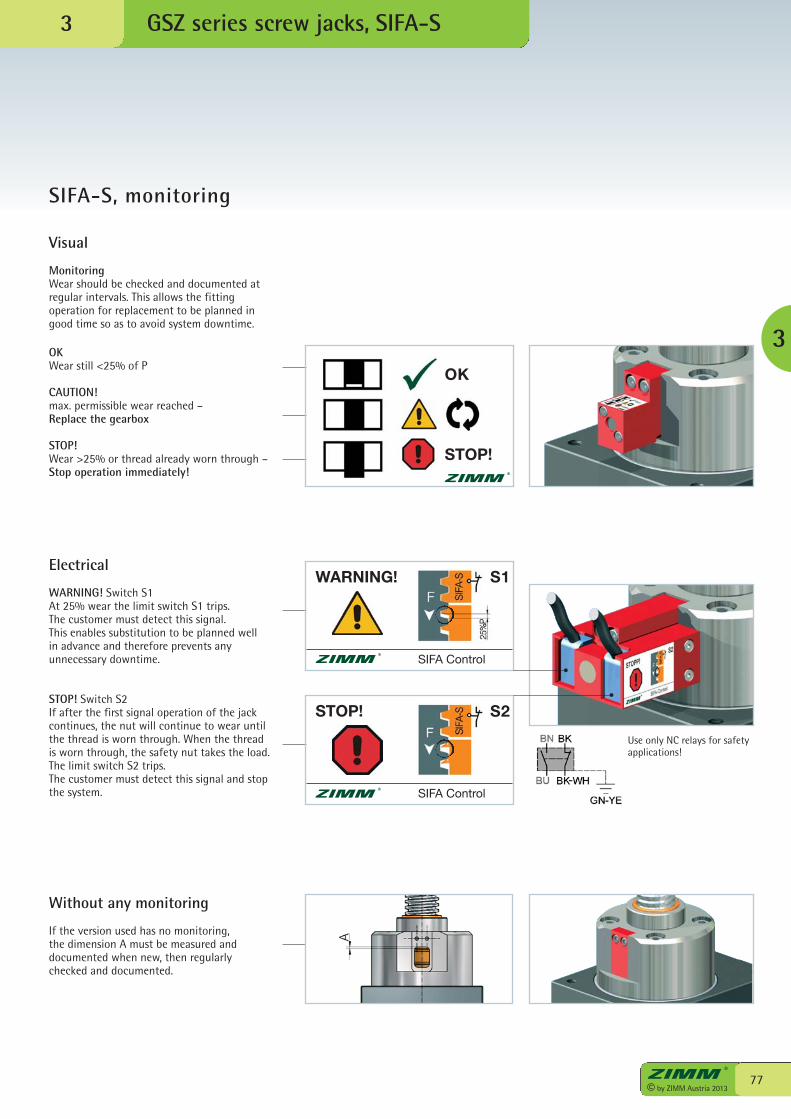
77© by ZIMM Austria 2013
3 GSZ series screw jacks, SIFA-S
3
Visual
MonitoringWear should be checked and documented atregular intervals. This allows the fittingoperation for replacement to be planned ingood time so as to avoid system downtime.
Electrical
WARNING! Switch S1At 25% wear the limit switch S1 trips.The customer must detect this signal.This enables substitution to be planned wellin advance and therefore prevents anyunnecessary downtime.
STOP! Switch S2If after the first signal operation of the jackcontinues, the nut will continue to wear untilthe thread is worn through. When the threadis worn through, the safety nut takes the load.The limit switch S2 trips.The customer must detect this signal and stopthe system.
Without any monitoring
If the version used has no monitoring,the dimension A must be measured anddocumented when new, then regularlychecked and documented.
OKWear still <25% of P
CAUTION!max. permissible wear reached –Replace the gearbox
STOP!Wear >25% or thread already worn through –Stop operation immediately!
SIFA-S, monitoring
Use only NC relays for safetyapplications!
OK
STOP!
WARNING!
SIFA Control
STOP!
SIFA Control
S1
S2
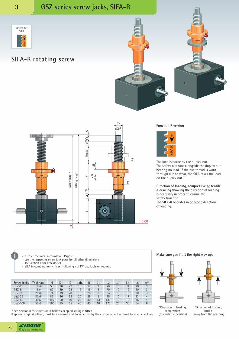
© by ZIMM Austria 201378
GSZ series screw jacks, SIFA-R3
SIFA-R rotating screw
“Direction of loading,compressive”
(towards the gearbox)
“Direction of loading,tensile”
(away from the gearbox)
Screw jacks Tr thread H D1 D d3j6 O L1 L2 L31) L4 L5 A2)
GSZ-2 16x4 50 26 22 10 12 3 70 10 11 20 3 GSZ-5 18x4 62 29 24 12 15 8 70 10 12 20 3 GSZ-10 20x4 74 39 28 15 20 8 84 10 16 20 3 GSZ-25 30x6 82 46 38 20 25 5 95 10 17 23 4 GSZ-50 40x7 116 60 50 25 30 13 133 10 19 36 4 GSZ-100 55x9 160 85 65 40 45 10 173 20 30 54 6
1) See Section 8 for extension if bellows or spiral spring is fitted2) approx. original setting, must be measured and documented by the customer, and referred to when checking
- further technical information: Page 75- see the respective screw jack page for all other dimensions- see Section 4 for accessories- SIFA in combination with self-aligning nut PM available on request
Function R version
The load is borne by the duplex nut.The safety nut runs alongside the duplex nut,bearing no load. If the nut thread is wornthrough due to wear, the SIFA takes the loadon the duplex nut.
Direction of loading, compressive or tensileA drawing showing the direction of loadingis necessary in order to ensure thesafety function.The SIFA-R operates in only one directionof loading.
Make sure you fit it the right way up:
Safety nutSIFA
Scre
wle
ngth
Fitt
ing
heig
ht
Stro
ke
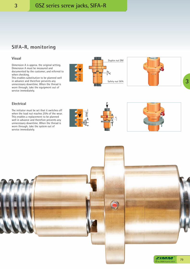
79© by ZIMM Austria 2013
GSZ series screw jacks, SIFA-R
3
3
SIFA-R, monitoring
Visual
Dimension A is approx. the original setting.Dimension A must be measured anddocumented by the customer, and referred towhen checking.This enables substitution to be planned well in advance and therefore prevents anyunnecessary downtime. When the thread isworn through, take the equipment out ofservice immediately.
Electrical
The initiator must be set that it switches offwhen the load nut reaches 25% of the wear.This enables a replacement to be planned well in advance and therefore prevents anyunnecessary downtime. When the thread isworn through, take the system out ofservice immediately.
Duplex nut DM
Safety nut SIFA
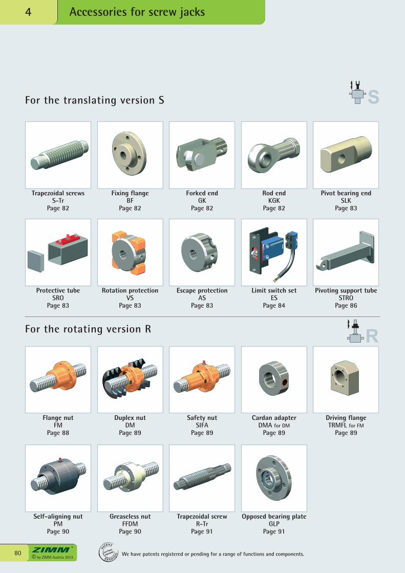
For the translating version S
Accessories for screw jacks4
© by ZIMM Austria 201380
For the rotating version R
Trapezoidal screwsS-Tr
Page 82
Fixing flangeBF
Page 82
Forked endGK
Page 82
Rod endKGK
Page 82
Pivot bearing endSLK
Page 83
Protective tube SRO
Page 83
Rotation protectionVS
Page 83
Escape protectionAS
Page 83
Limit switch setES
Page 84
Pivoting support tubeSTRO
Page 86
Flange nutFM
Page 88
Self-aligning nutPM
Page 90
Duplex nutDM
Page 89
Safety nutSIFA
Page 89
Cardan adapterDMA for DM
Page 89
Driving flangeTRMFL for FM
Page 89
Greaseless nutFFDM
Page 90
Trapezoidal screwR-Tr
Page 91
Opposed bearing plateGLP
Page 91
We have patents registered or pending for a range of functions and components.
PA
TENT
P E N D I NG
zum Patent
angemeldet
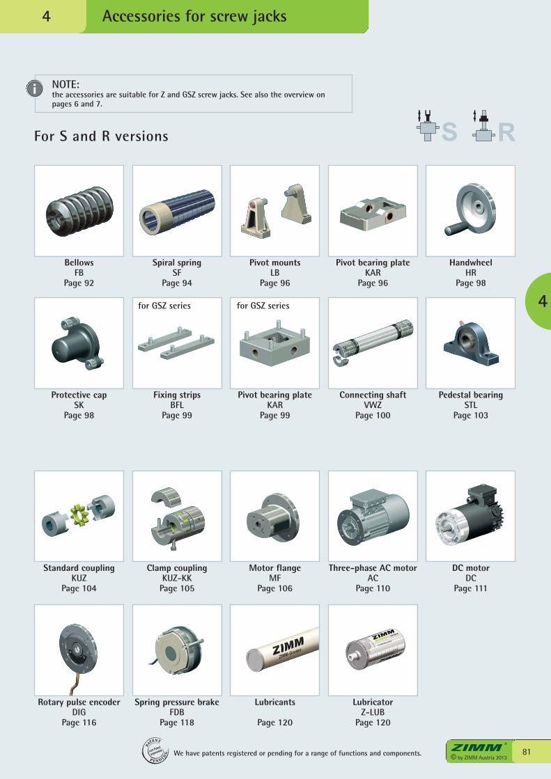
For S and R versions
Accessories for screw jacks
81© by ZIMM Austria 2013
BellowsFB
Page 92
Spiral springSF
Page 94
Pivot mountsLB
Page 96
Pivot bearing plateKAR
Page 96
HandwheelHR
Page 98
Protective capSK
Page 98
Fixing stripsBFL
Page 99
Pivot bearing plateKAR
Page 99
Connecting shaftVWZ
Page 100
Pedestal bearingSTL
Page 103
Standard couplingKUZ
Page 104
Rotary pulse encoderDIG
Page 116
Clamp couplingKUZ-KK
Page 105
Motor flangeMF
Page 106
Three-phase AC motor AC
Page 110
DC motor DC
Page 111
Spring pressure brakeFDB
Page 118
Lubricants
Page 120
LubricatorZ-LUB
Page 120
4
4
We have patents registered or pending for a range of functions and components.
PA
TENT
P E N D I NG
zum Patent
angemeldet
for GSZ series for GSZ series
NOTE:the accessories are suitable for Z and GSZ screw jacks. See also the overview onpages 6 and 7.
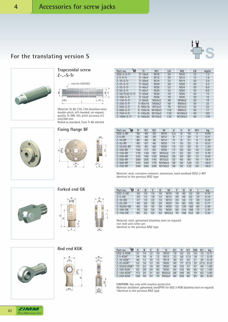
© by ZIMM Austria 201382
Accessories for screw jacks4
For the translating version S
CB
G1
GSW
N1
DA
H1
H
H
D-H9A
G
F M
C
I
BA
d(4x)
D
M
D1
h
H
M1
TrTr 16x4Tr 18x4Tr 20x4Tr 30x6Tr 40x7Tr 40x7Tr 50x8Tr 55x9Tr 60x9Tr 80x16Tr 100x16Tr 120x16Tr 140x20Tr 160x20
M1M10M12M14M20M30M30M36M36
M42x2M56x2M72x3M100x3M110x3M110x3
LA2429323853537676485878118130130
M2M10M12M14M20M24M30M36M36
M48x2M64x3M72x3M85x3M100x3M100x3
LB1515202030303030303035404040
kg/m1.21.62.04.58.08.0131619325277105139
Fixing flange BF
Forked end GK
Rod end KGK
Part no.GSZ-2-BFZ-5-BFZ-10-BFZ-25-BFZ-35/50-BFZ-100-BFZ-150-BFZ-250-BFZ-350-BFZ-500-BFZ-750-BF
Part no.GSZ-2-GKZ-5-GKZ-10-GKZ-25-GKZ-35/50-GKZ-100-GKZ-150-GK
A20242740607085
B10121420303642
C15182230425463
D10121420303542
F18202434526070
G40485680120144168
H526272105160188232
I20242840607284
kg0.100.160.240.712.483.705.30
Material: steel, corrosion-resistant; aluminium, hard anodised (GSZ-2-BF)identical to the previous MSZ type
Material: steel, galvanised (stainless steel on request)incl. bolt and cotter pinidentical to the previous MSZ type
CAUTION: Use only with rotation protectionMaterial: steel/steel. galvanised; steel/PTFE for GSZ-2-KGK (stainless steel on request)*identical to the previous MSZ type
LB LA
M2
M1
Tr
L
Trapezoidal screw Z-..-S-Tr
Material: St 60, C35, C45 (stainless steel,double-pitch, left-handed, on request,quality 7e DIN 103, pitch accuracy 0.2mm/300 mmRolled as standard, from Tr 80 whirled
Part no.GSZ-2-S-TrZ-5-S-TrZ-10-S-TrZ-25-S-TrZ-35-S-TrZ-50-S-TrZ-50/Tr50-S-TrZ-100-S-TrZ-150-S-TrZ-250-S-TrZ-350-S-TrZ-500-S-TrZ-750-S-TrZ-1000-S-Tr
only for AS/VS/ES
D2
D50658090110150170210260310340
D14048606785117130165205240265
D226293846608590120145170200
MM10M12M14M20M30M36
M42x2M56x2M72x3M100x3M110x3
d5.59111113172126323838
h6781015202530404050
H162021233050506080120132
M155688101012161620
kg0.040.210.380.571.203.504.709.5018.430.036.0
MM10M12M14M20M30M36
M42x2
Part no.GSZ-2-KGKZ-5-KGK*Z-10-KGK*Z-25-KGK*Z-35/50-KGK*Z-100-KGKZ-150-KGK*Z-250-KGK
A313440537392112160
B1410121622283549
C128101319243143
D1012152030405070
GM10M12M14M20M30M36
M42x2M56x2
G11923304056656880
H43506177110142160200
H115
17.520
27.537465680
SW1618213241607085
N1151720
27.540526280
kg0.110.100.160.321.001.903.608.30
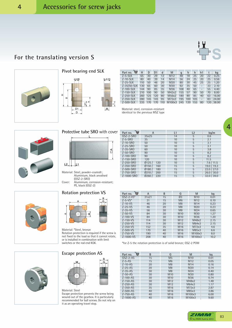
83© by ZIMM Austria 2013
Accessories for screw jacks
4
For the translating version S
Protective tube SRO with cover
Rotation protection VS
Material: SteelEscape protection prevents the screw beingwound out of the gearbox. It is particularlyrecommended for ball screws. Do not rely onit as an operating travel stop.
Escape protection AS
Part no.GSZ-2-SROZ-5-SROZ-10-SROZ-25-SROZ-35-SROZ-50-SROZ-100-SROZ-150-SROZ-250-SROZ-350-SROZ-500-SROZ-750-SROZ-1000-SRO
A 35x25 35 50 50 60 90 90 120 Ø125 / 120 Ø150 / 160 Ø180 / 180 Ø210 / 200 Ø260 / 220
L114101010101010101015151515
L25555555555555
kg/m 0.6 2.1 3.1 3.1 3.8 8.2 8.2 11.5 7.6 / 11.5 19.0 / 19.3 22.0 / 27.0 26.0 / 30.0 32.0 / 39.0
Part no.GSZ-2-ASZ-5-ASZ-10-ASZ-25-ASZ-35-ASZ-50-ASZ-100-ASZ-150-ASZ-250-ASZ-350-ASZ-500-ASZ-750-ASZ-1000-AS
B15152020303030303035404040
GM5M6M8M8M8M10M10M12M12M16M16M16M16
MM10M12M14M20M24M30M36
M48x2M64x3M72x3M85x3M100x3M100x3
kg0.010.050.160.140.400.800.741.481.172.873.866.009.60
Part no.GSZ-2-VS*Z-5-VS*Z-10-VSZ-25-VSZ-35-VSZ-50-VSZ-100-VSZ-150-VSZ-250-VSZ-350-VSZ-500-VSZ-750-VSZ-1000-VS
A31x21
314646568484114114152170190208
B15152020303030303035404040
GØ3M6M8M8M8M10M10M12M12M16M16M16M16
MM10M12M14M20M24M30M36
M48x2M64x3M72x3M85x3M100x3M100x3
kg0.010.100.230.230.651.271.202.152.154.66.68.010.2
Material: *Steel, bronzeRotation protection is required if the screw isnot fixed to the load so that it cannot rotate,or is installed in combination with limitswitches or the rod end KGK. *for Z-5 the rotation protection is of solid bronze; GSZ-2 POM
4
d-H8
D1D
M
h1h
g
H
b-h10
t
Pivot bearing end SLK Part no.Z-5-SLKZ-10-SLKZ-25-SLKZ-35/50-SLKZ-100-SLKZ-150-SLKZ-250-SLKZ-350-SLKZ-500-SLK
H6580110130144210260280335
D3040506590100125145170
D1293946608590120145170
d1214203035508095110
MM12M14M20M30M36
M42x2M56x2M72x3M100x3
g48568092108155180195245
b18243035405780100120
h25254550659085105155
h1202025--
5040-
80
t2225253355706383120
kg0.250.561.202.104.408.0016.0024.0038.00
Material: steel, corrosion-resistantidentical to the previous MSZ type
Material: Steel, powder-coatedt ; Aluminium, black anodised
(GSZ-2-SRO)Cover: Aluminium, corrosion-resistant; PE, black (GSZ-2)
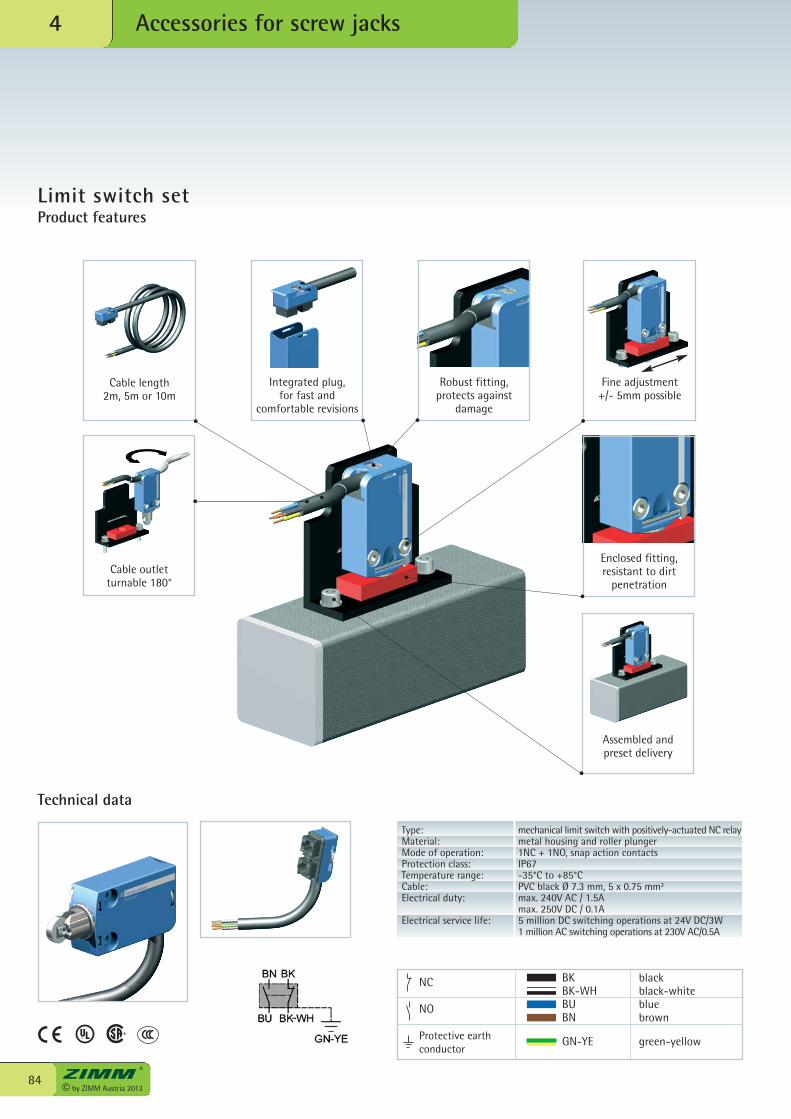
© by ZIMM Austria 201384
Accessories for screw jacks4
Limit switch setProduct features
Integrated plug,for fast and
comfortable revisions
Fine adjustment+/- 5mm possible
Assembled and preset delivery
Cable outletturnable 180°
Cable length2m, 5m or 10m
Robust fitting,protects against
damage
Enclosed fitting,resistant to dirt
penetration
Technical data
Type: mechanical limit switch with positively-actuated NC relayMaterial: metal housing and roller plungerMode of operation: 1NC + 1NO, snap action contactsProtection class: IP67Temperature range: -35°C to +85°CCable: PVC black Ø 7.3 mm, 5 x 0.75 mm2
Electrical duty: max. 240V AC / 1.5A max. 250V DC / 0.1AElectrical service life: 5 million DC switching operations at 24V DC/3W 1 million AC switching operations at 230V AC/0.5A
BK black BK-WH black-white BU blue BN brown
GN-YE green-yellow
NC
NO
Protective earthconductor
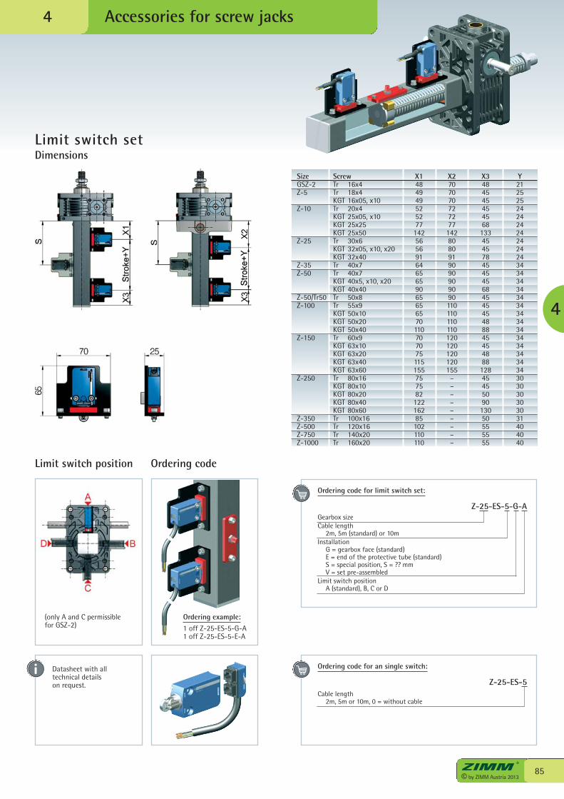
85© by ZIMM Austria 2013
Accessories for screw jacks
4
4
Ordering code
Ordering example:
1 off Z-25-ES-5-G-A1 off Z-25-ES-5-E-A
Size Screw X1 X2 X3 YGSZ-2 Tr 16x4 48 70 48 21Z-5 Tr 18x4 49 70 45 25 KGT 16x05, x10 49 70 45 25Z-10 Tr 20x4 52 72 45 24 KGT 25x05, x10 52 72 45 24 KGT 25x25 77 77 68 24 KGT 25x50 142 142 133 24Z-25 Tr 30x6 56 80 45 24 KGT 32x05, x10, x20 56 80 45 24 KGT 32x40 91 91 78 24Z-35 Tr 40x7 64 90 45 34Z-50 Tr 40x7 65 90 45 34 KGT 40x5, x10, x20 65 90 45 34 KGT 40x40 90 90 68 34Z-50/Tr50 Tr 50x8 65 90 45 34Z-100 Tr 55x9 65 110 45 34 KGT 50x10 65 110 45 34 KGT 50x20 70 110 48 34 KGT 50x40 110 110 88 34Z-150 Tr 60x9 70 120 45 34 KGT 63x10 70 120 45 34 KGT 63x20 75 120 48 34 KGT 63x40 115 120 88 34 KGT 63x60 155 155 128 34Z-250 Tr 80x16 75 – 45 30 KGT 80x10 75 – 45 30 KGT 80x20 82 – 50 30 KGT 80x40 122 – 90 30 KGT 80x60 162 – 130 30Z-350 Tr 100x16 85 – 50 31Z-500 Tr 120x16 102 – 55 40Z-750 Tr 140x20 110 – 55 40Z-1000 Tr 160x20 110 – 55 40
Limit switch set Dimensions
(only A and C permissible for GSZ-2)
Ordering code for limit switch set:
Z-25-ES-5-G-AGearbox sizeCable length 2m, 5m (standard) or 10mInstallation G = gearbox face (standard) E = end of the protective tube (standard) S = special position, S = ?? mm V = set pre-assembledLimit switch position A (standard), B, C or D
Ordering code for an single switch:
Z-25-ES-5Cable length 2m, 5m or 10m, 0 = without cable
Limit switch position
Datasheet with alltechnical detailson request.
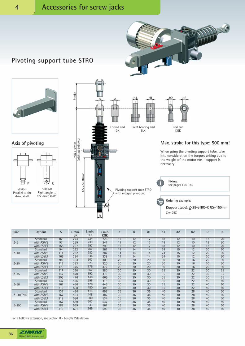
© by ZIMM Austria 201386
Accessories for screw jacks4
Pivoting support tube STRO
D
121212202020202020303030404040404040404040
B
202020303030303030353535505050505050505050
Axis of pivoting
STRO-PParallel to the
drive shaft
STRO-RRight angle tothe drive shaft
P R
Forked endGK
Pivot bearing endSLK
Rod endKGK
Pivoting support tube STROwith integral pivot end
Stro
keLm
in +
str
oke
(wit
hout
bel
low
s)G
S =
S+st
roke
Max. stroke for this type: 500 mm!
When using the pivoting support tube, takeinto consideration the torques arising due tothe weight of the motor etc. - support isnecessary!
Size
Z-5
Z-10
Z-25
Z-35
Z-50
Z-50/Tr50
Z-100
d
121212141414202020303030303030353535353535
b
121212141414202020303030303030363636363636
d1
121212141414202020303030303030353535353535
b1
181818242424303030353535353535404040404040
d2
121212151515202020303030303030404040404040
b2
101010121212161616222222222222282828282828
L min.KGK226241299267287339300320372380410466416446498452482534537567599
L min.SLK224239297262282334303323375362392448398428480418448500503533565
S
82971559411416698118170117147203137167219137167219157187219
Options
Standardwith AS/VSwith ESSETStandard
with AS/VSwith ESSETStandard
with AS/VSwith ESSETStandard
with AS/VSwith ESSETStandard
with AS/VSwith ESSETStandard
with AS/VSwith ESSETStandard
with AS/VSwith ESSET
Ordering example: (Support tube): Z-25-STRO-P, GS=150mmZ or GSZ
For a bellows extension, see Section 8 - Length Calculation
L min.GK224239297262282334303323375390420476426456508454484536539569601
Fixing:see pages 154, 159
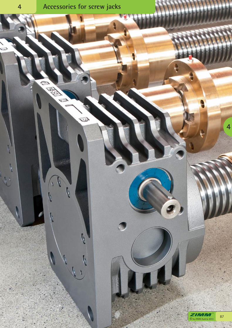
Accessories for screw jacks4
87© by ZIMM Austria 2013
4
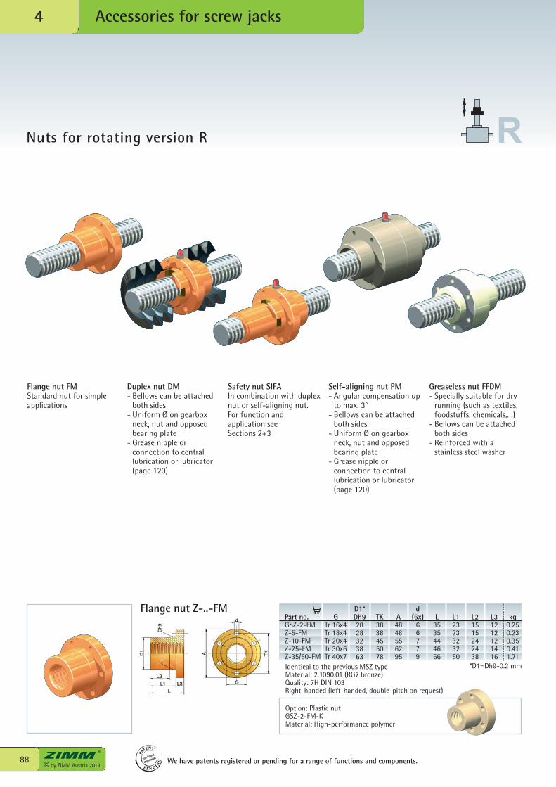
© by ZIMM Austria 201388
Accessories for screw jacks4
Flange nut FMStandard nut for simpleapplications
Duplex nut DM- Bellows can be attached
both sides- Uniform Ø on gearbox
neck, nut and opposedbearing plate
- Grease nipple orconnection to centrallubrication or lubricator(page 120)
Safety nut SIFAIn combination with duplexnut or self-aligning nut.For function andapplication seeSections 2+3
Self-aligning nut PM- Angular compensation up
to max. 3°- Bellows can be attached
both sides- Uniform Ø on gearbox
neck, nut and opposedbearing plate
- Grease nipple orconnection to centrallubrication or lubricator(page 120)
Greaseless nut FFDM- Specially suitable for dry
running (such as textiles,foodstuffs, chemicals,…)
- Bellows can be attachedboth sides
- Reinforced with astainless steel washer
Flange nut Z-..-FMPart no.GSZ-2-FMZ-5-FMZ-10-FMZ-25-FMZ-35/50-FM
GTr 16x4Tr 18x4Tr 20x4Tr 30x6Tr 40x7
D1*Dh92828323863
TK3838455078
A4848556295
d (6x)
66779
L3535444666
L12323323250
L21515242438
L31212121416
kg0.250.230.350.411.71
Nuts for rotating version R
We have patents registered or pending for a range of functions and components.
PA
TENT
P E N D I NG
zum Patent
angemeldet
Identical to the previous MSZ typeMaterial: 2.1090.01 (RG7 bronze)Quality: 7H DIN 103Right-handed (left-handed, double-pitch on request)
*D1=Dh9-0.2 mm
Option: Plastic nutGSZ-2-FM-KMaterial: High-performance polymer
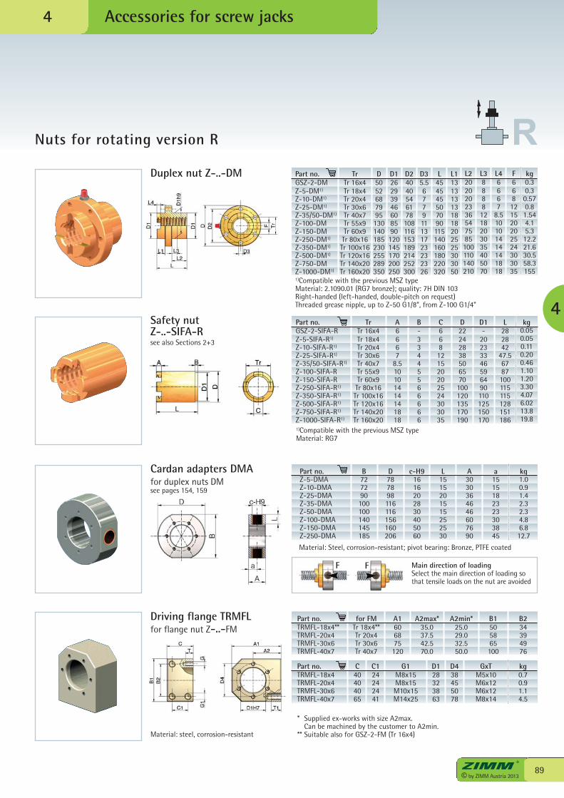
FF
89© by ZIMM Austria 2013
Accessories for screw jacks
Nuts for rotating version R
4
Duplex nut Z-..-DM
Safety nut Z-..-SIFA-R
Part no.GSZ-2-DMZ-5-DM1)
Z-10-DM1)
Z-25-DM1)
Z-35/50-DM1)
Z-100-DMZ-150-DMZ-250-DM1)
Z-350-DM1)
Z-500-DM1)
Z-750-DMZ-1000-DM1)
F668121520202524303035
see also Sections 2+3
TrTr 16x4Tr 18x4Tr 20x4Tr 30x6Tr 40x7Tr 55x9Tr 60x9Tr 80x16Tr 100x16Tr 120x16Tr 140x20Tr 160x20
D5052687995130140185230255289350
D126293946608590120145170200250
D24040546178108116153189214252300
D35.5677911131723232326
L454545507090115140160180220320
L1131313131818202525303050
L22020202336547585100110140210
L388881218203035405070
L46667
8.510101414141818
kg0.30.30.570.81.544.15.312.221.630.558.3155
L282842
47.56787100115115128151186
kg0.050.050.110.200.461.101.203.304.076.0213.819.8
D1-
20233346596490110125150170
D22242838506570100120135170190
C668121520202524303035
B-33445566666
A6667
8.510101414141818
TrTr 16x4Tr 18x4Tr 20x4Tr 30x6Tr 40x7Tr 55x9Tr 60x9Tr 80x16Tr 100x16Tr 120x16Tr 140x20Tr 160x20
Part no.GSZ-2-SIFA-RZ-5-SIFA-R1)
Z-10-SIFA-R1)
Z-25-SIFA-R1)
Z-35/50-SIFA-R1)
Z-100-SIFA-RZ-150-SIFA-RZ-250-SIFA-R1)
Z-350-SIFA-R1)
Z-500-SIFA-R1)
Z-750-SIFA-R1)
Z-1000-SIFA-R1)
Cardan adapters DMAfor duplex nuts DMsee pages 154, 159
B727290100100140145185
D787898116116156160206
c-H91616202830405060
L1515201515252530
A3030364646607690
a1515182323303845
kg1.00.91.42.32.34.86.812.7
Material: Steel, corrosion-resistant; pivot bearing: Bronze, PTFE coated
Part no.Z-5-DMAZ-10-DMAZ-25-DMAZ-35-DMAZ-50-DMAZ-100-DMAZ-150-DMAZ-250-DMA
Main direction of loadingSelect the main direction of loading sothat tensile loads on the nut are avoided
Part no.TRMFL-18x4**TRMFL-20x4TRMFL-30x6TRMFL-40x7
A1606875120
B1505865100
B234394976
Part no.TRMFL-18x4TRMFL-20x4TRMFL-30x6TRMFL-40x7
GxTM5x10M6x12M6x12M8x14
kg0.70.91.14.5
D128323863
D438455078
Driving flange TRMFLfor flange nut Z-..-FM
for FMTr 18x4**Tr 20x4Tr 30x6Tr 40x7
A2max*35.037.542.570.0
A2min*25.029.032.550.0
C40404065
C124242441
G1M8x15M8x15M10x15M14x25
* Supplied ex-works with size A2max. Can be machined by the customer to A2min.** Suitable also for GSZ-2-FM (Tr 16x4)Material: steel, corrosion-resistant
4
1)Compatible with the previous MSZ typeMaterial: 2.1090.01 (RG7 bronze); quality: 7H DIN 103Right-handed (left-handed, double-pitch on request)Threaded grease nipple, up to Z-50 G1/8”, from Z-100 G1/4”
1)Compatible with the previous MSZ typeMaterial: RG7
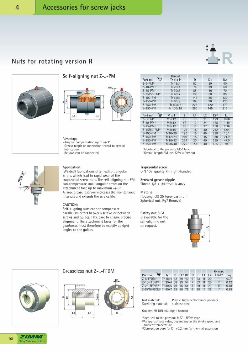
© by ZIMM Austria 201390
Accessories for screw jacks4
Nuts for rotating version R
Self-aligning nut Z-..-PM
1)Identical to the previous MSZ type2)Overall length PM incl. SIFA safety nut
Application:(Welded) fabrications often exhibit angularerrors, which lead to rapid wear of thetrapezoidal screw nuts. The self-aligning nut PMcan compensate small angular errors on theattachment face up to maximum +/-3°.A large grease reservoir increases the maintenanceintervals and extends the service life.
CAUTION:Self-aligning nuts cannot compensateparallelism errors between screws or betweenscrews and guides. Take care to ensure precisealignment. The attachment faces for thegearboxes must therefore be exactly at rightangles to the guides.
Trapezoidal screwDIN 103, quality 7H, right-handed
Screwed grease nippleThread 1/8“ / 1/4“ from Tr 40x7
MaterialHousing: GG 25 (grey cast iron)Spherical nut: Rg7 (bronze)
Safety nut SIFAis available for the self-aligning nut on request.
Nut material: Plastic, high-performance polymerSteel ring material: stainless steel
Quality: 7H DIN 103, right-handed
1)Identical to the previous MSZ - FFDM type2)As approximate value, depending on the stroke speed andambient temperature
3)Connection bore for D1 +0.2 mm for thermal expansion
Part no.Z-5-FFDM1)
Z-10-FFDM1)
Z-25-FFDM1)
Z-35/50-FFDM1)
D52687995
D240546178
D36779
L53535985
L111111113
L220202335
kN max.Load2)
1257
kg0.070.120.180.38
Greaseless nut Z-..-FFDMTr
Tr 18x4Tr 20x4Tr 30x6Tr 40x7
ThreadPart no. Tr d x P D D1 D2Z-5-PM1) Tr 18x4 52 29 40Z-10-PM1) Tr 20x4 74 39 60Z-25-PM1) Tr 30x6 88 46 70Z-35/50-PM1) Tr 40x7 105 60 85Z-100-PM Tr 55x9 148 85 120Z-150-PM Tr 60x9 165 90 125Z-250-PM Tr 80x16 225 120 170Z-350-PM Tr 100x16 280 145 215
Part no. M x T L L1 L2 LS2) kgZ-5-PM1) M5x12 78 13 21 123 0.66Z-10-PM1) M6x12 83 13 24 128 1.49Z-25-PM1) M6x12 95 13 27 158 2.36Z-35/50-PM1) M8x16 129 15 30 212 5.04Z-100-PM M10x20 190 15 45 298 15.1Z-150-PM M12x24 210 15 45 330 21.9Z-250-PM M16x32 224 20 40 369 47.0Z-350-PM M20x40 275 20 40 455 94
Advantage-Angular compensation up to +/-3°-Grease nipple or connection thread to central
lubrication-Bellows can be connected
D13)
29394660
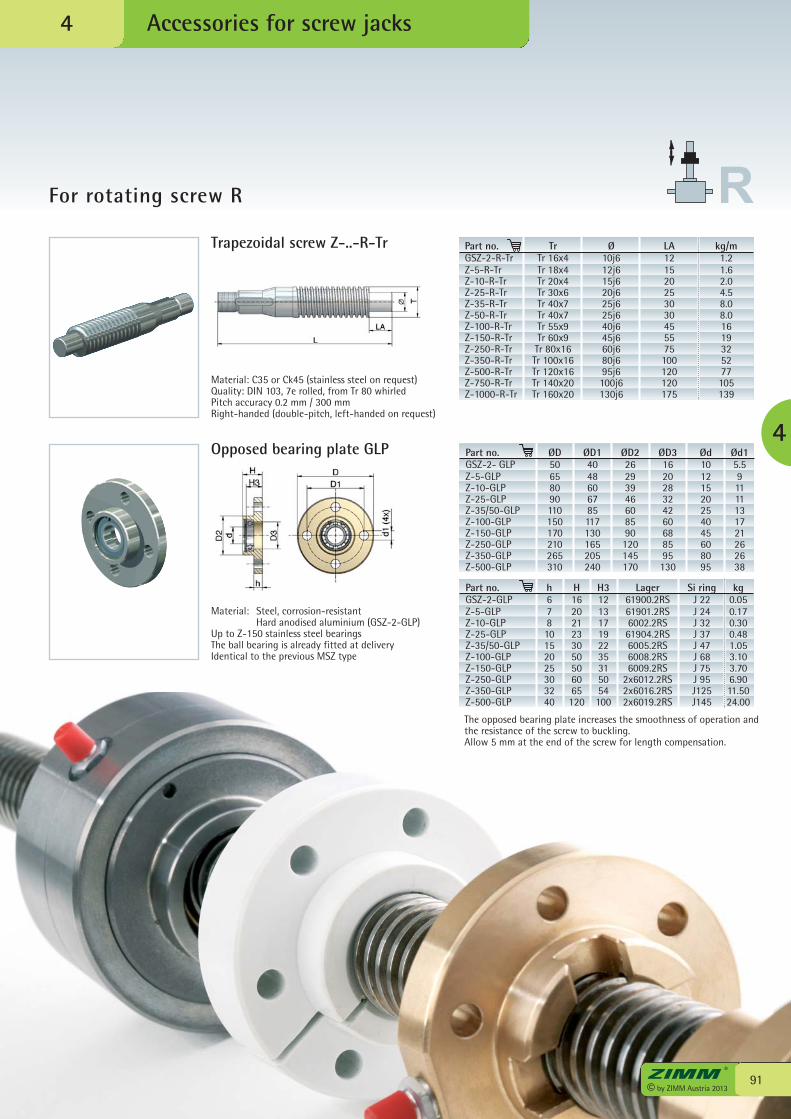
91© by ZIMM Austria 2013
Accessories for screw jacks
For rotating screw R
4
4
Part no.GSZ-2-R-TrZ-5-R-Tr Z-10-R-TrZ-25-R-TrZ-35-R-TrZ-50-R-TrZ-100-R-TrZ-150-R-TrZ-250-R-TrZ-350-R-TrZ-500-R-TrZ-750-R-TrZ-1000-R-Tr
Ø10j612j615j620j625j625j640j645j660j680j695j6100j6130j6
LA121520253030455575100120120175
kg/m1.21.62.04.58.08.01619325277105139
Material: C35 or Ck45 (stainless steel on request)Quality: DIN 103, 7e rolled, from Tr 80 whirledPitch accuracy 0.2 mm / 300 mmRight-handed (double-pitch, left-handed on request)
Part no.GSZ-2- GLPZ-5-GLPZ-10-GLPZ-25-GLPZ-35/50-GLPZ-100-GLPZ-150-GLPZ-250-GLPZ-350-GLPZ-500-GLP
ØD14048606785117130165205240
ØD226293946608590120145170
ØD3162028324260688595130
Ød15.591111131721262638
Part no.GSZ-2-GLPZ-5-GLPZ-10-GLPZ-25-GLPZ-35/50-GLPZ-100-GLPZ-150-GLPZ-250-GLPZ-350-GLPZ-500-GLP
h67810152025303240
H162021233050506065120
H3121317192235315054100
Lager61900.2RS61901.2RS6002.2RS61904.2RS6005.2RS6008.2RS6009.2RS
2x6012.2RS2x6016.2RS2x6019.2RS
Si ringJ 22J 24J 32J 37J 47J 68J 75J 95J125J145
kg0.050.170.300.481.053.103.706.9011.5024.00
Material: Steel, corrosion-resistant Hard anodised aluminium (GSZ-2-GLP)Up to Z-150 stainless steel bearingsThe ball bearing is already fitted at deliveryIdentical to the previous MSZ type
Opposed bearing plate GLP
Trapezoidal screw Z-..-R-Tr TrTr 16x4Tr 18x4Tr 20x4Tr 30x6Tr 40x7Tr 40x7Tr 55x9Tr 60x9Tr 80x16Tr 100x16Tr 120x16Tr 140x20Tr 160x20
ØD50658090110150170210265310
Ød10121520254045608095
The opposed bearing plate increases the smoothness of operation andthe resistance of the screw to buckling.Allow 5 mm at the end of the screw for length compensation.
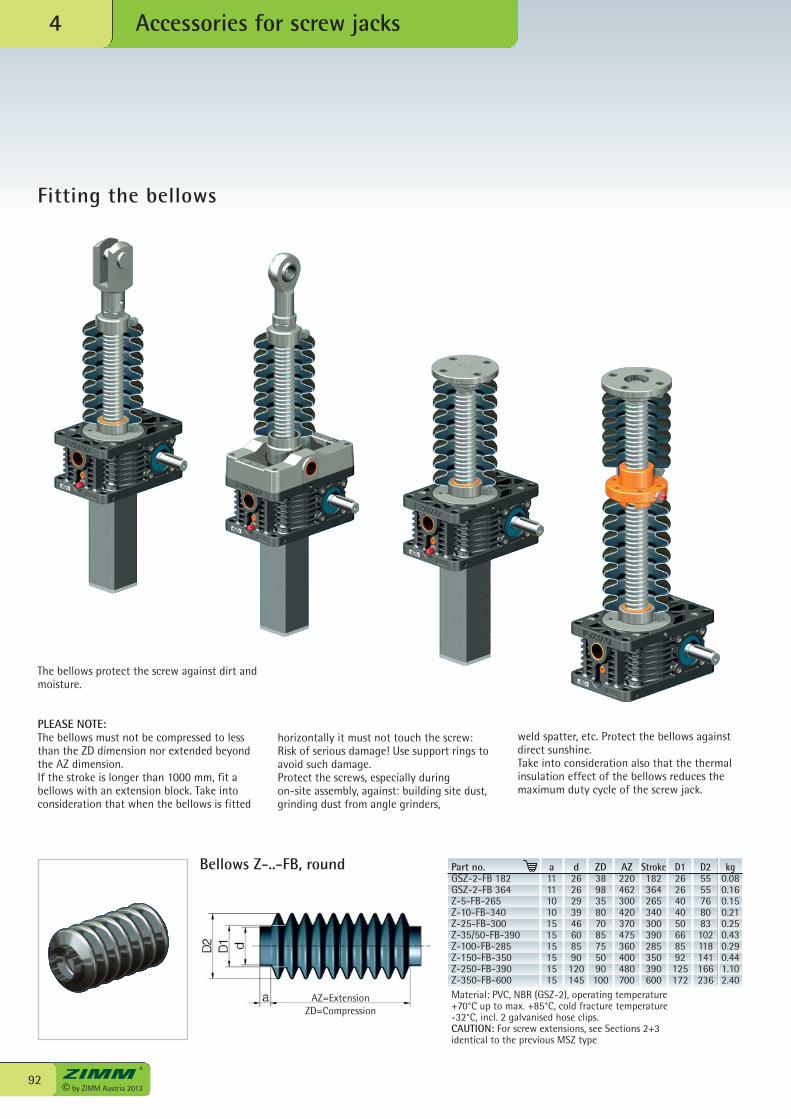
© by ZIMM Austria 201392
Accessories for screw jacks4
Fitting the bellows
AZ=ExtensionZD=Compression
The bellows protect the screw against dirt andmoisture.
PLEASE NOTE:The bellows must not be compressed to lessthan the ZD dimension nor extended beyondthe AZ dimension.If the stroke is longer than 1000 mm, fit abellows with an extension block. Take intoconsideration that when the bellows is fitted
horizontally it must not touch the screw: Risk of serious damage! Use support rings toavoid such damage.Protect the screws, especially during on-site assembly, against: building site dust,grinding dust from angle grinders,
Material: PVC, NBR (GSZ-2), operating temperature+70°C up to max. +85°C, cold fracture temperature -32°C, incl. 2 galvanised hose clips. CAUTION: For screw extensions, see Sections 2+3identical to the previous MSZ type
Part no.GSZ-2-FB 182GSZ-2-FB 364Z-5-FB-265Z-10-FB-340Z-25-FB-300Z-35/50-FB-390Z-100-FB-285Z-150-FB-350Z-250-FB-390Z-350-FB-600
a11111010151515151515
d2626293946608590120145
ZD389835807085755090100
AZ220462300420370475360400480700
Stroke182364265340300390285350390600
D12626404050668592125172
D25555768083102118141166236
kg0.080.160.150.210.250.430.290.441.102.40
weld spatter, etc. Protect the bellows againstdirect sunshine.Take into consideration also that the thermalinsulation effect of the bellows reduces themaximum duty cycle of the screw jack.
Bellows Z-..-FB, round
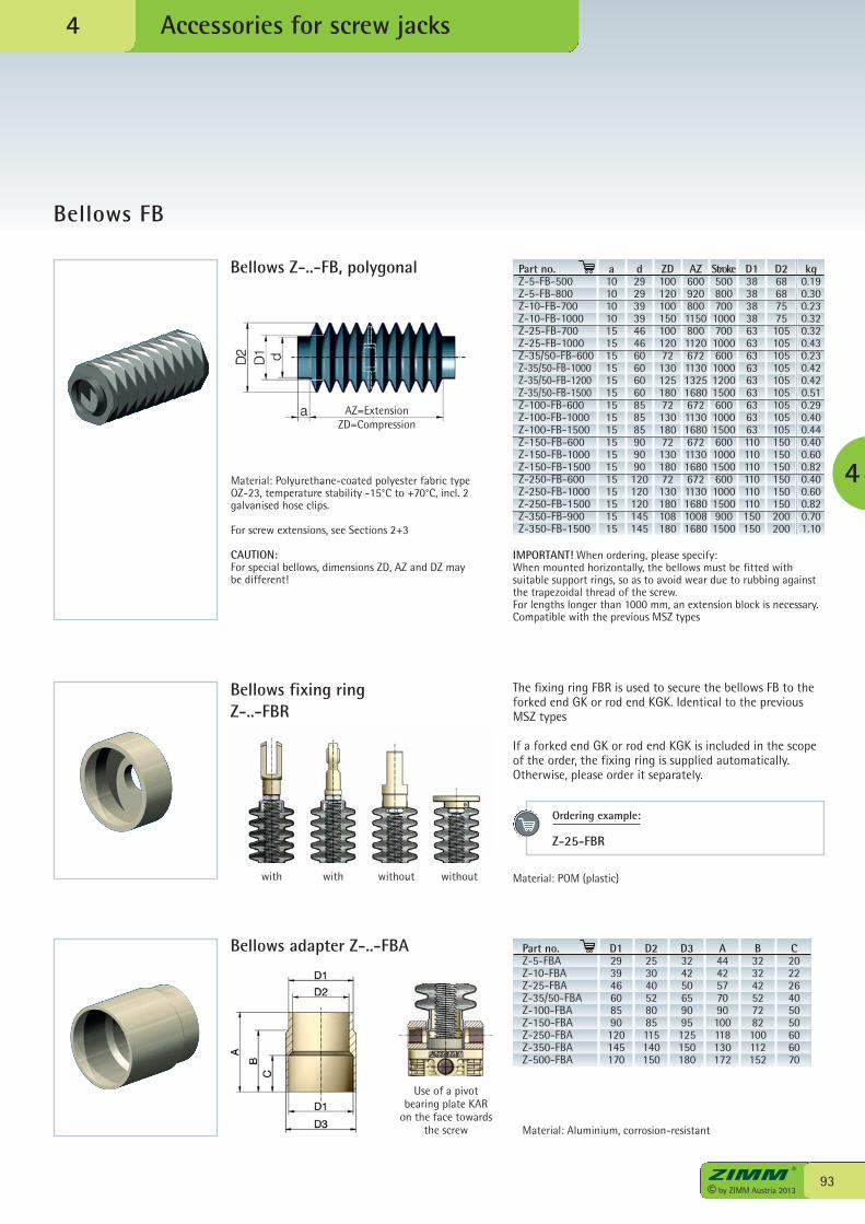
93© by ZIMM Austria 2013
Accessories for screw jacks
Bellows FB
4
4
AZ=ExtensionZD=Compression
Bellows Z-..-FB, polygonal
Bellows adapter Z-..-FBA
IMPORTANT! When ordering, please specify:When mounted horizontally, the bellows must be fitted withsuitable support rings, so as to avoid wear due to rubbing againstthe trapezoidal thread of the screw.For lengths longer than 1000 mm, an extension block is necessary.Compatible with the previous MSZ types
Part no.Z-5-FBAZ-10-FBAZ-25-FBAZ-35/50-FBAZ-100-FBAZ-150-FBAZ-250-FBAZ-350-FBAZ-500-FBA
D1293946608590120145170
D2253040528085115140150
D3324250659095125150180
A4442577090100118130172
B323242527282100112152
C202226405050606070
The fixing ring FBR is used to secure the bellows FB to theforked end GK or rod end KGK. Identical to the previousMSZ types
If a forked end GK or rod end KGK is included in the scopeof the order, the fixing ring is supplied automatically.Otherwise, please order it separately.
with with without without
a101010101515151515151515151515151515151515
d29293939464660606060858585909090120120120145145
ZD10012010015010012072130125180721301807213018072130180108180
AZ6009208001150800112067211301325168067211301680672113016806721130168010081680
Stroke500800700100070010006001000120015006001000150060010001500600100015009001500
D138383838636363636363636363110110110110110110150150
D268687575105105105105105105105105105150150150150150150200200
kg0.190.300.230.320.320.430.230.420.420.510.290.400.440.400.600.820.400.600.820.70 1.10
Material: Aluminium, corrosion-resistant
Use of a pivotbearing plate KAR
on the face towardsthe screw
Material: Polyurethane-coated polyester fabric type OZ-23, temperature stability -15°C to +70°C, incl. 2galvanised hose clips.
For screw extensions, see Sections 2+3
CAUTION:For special bellows, dimensions ZD, AZ and DZ maybe different!
Material: POM (plastic)
Bellows fixing ringZ-..-FBR
Part no.Z-5-FB-500Z-5-FB-800Z-10-FB-700Z-10-FB-1000Z-25-FB-700Z-25-FB-1000Z-35/50-FB-600Z-35/50-FB-1000Z-35/50-FB-1200Z-35/50-FB-1500Z-100-FB-600Z-100-FB-1000Z-100-FB-1500Z-150-FB-600Z-150-FB-1000Z-150-FB-1500Z-250-FB-600Z-250-FB-1000Z-250-FB-1500Z-350-FB-900Z-350-FB-1500
Ordering example:
Z-25-FBR
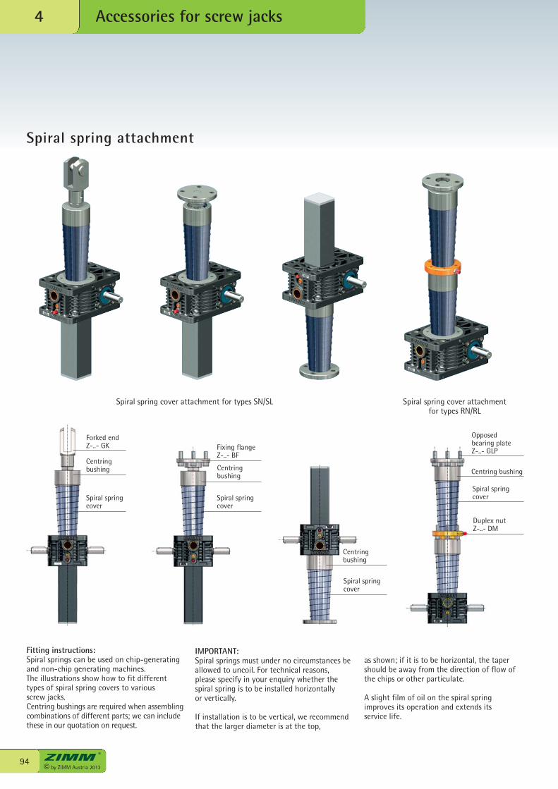
© by ZIMM Austria 201394
Accessories for screw jacks4
Spiral spring attachment
Spiral spring cover attachment for types SN/SL Spiral spring cover attachmentfor types RN/RL
Forked endZ-..- GK
Centringbushing
Spiral springcover
Fixing flangeZ-..- BF
Spiral springcover
Centring bushing
Duplex nutZ-..- DM
Opposed bearing plateZ-..- GLP
Centringbushing
Spiral springcover
Fitting instructions:Spiral springs can be used on chip-generatingand non-chip generating machines.The illustrations show how to fit differenttypes of spiral spring covers to variousscrew jacks.Centring bushings are required when assemblingcombinations of different parts; we can includethese in our quotation on request.
IMPORTANT:Spiral springs must under no circumstances beallowed to uncoil. For technical reasons,please specify in your enquiry whether thespiral spring is to be installed horizontallyor vertically.
If installation is to be vertical, we recommendthat the larger diameter is at the top,
as shown; if it is to be horizontal, the tapershould be away from the direction of flow ofthe chips or other particulate.
A slight film of oil on the spiral springimproves its operation and extends itsservice life.
Centringbushing
Spiral springcover
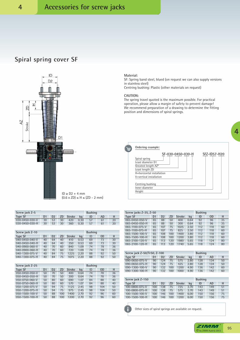
Type SF040-0450-040-V040-0450-040-H040-0900-060-V040-0900-060-H040-1300-075-V040-1300-075-H
D1404040404040
D2646470708484
ZD404060607575
Stroke41035084072012251075
kg0.530.531.091.092.202.20
ID696974748888
OD737378789292
H303036365050
95© by ZIMM Austria 2013
Accessories for screw jacks
Spiral spring cover SF
4
4
Material:SF: Spring band steel, blued (on request we can also supply versionsin stainless steel)Centring bushing: Plastic (other materials on request)
CAUTION: The spring travel quoted is the maximum possible. For practicaloperation, please allow a margin of safety to prevent damage!We recommend preparation of a drawing to determine the fittingposition and dimensions of spiral springs.
Type SF030-0450-030-V030-0450-030-H
D13030
D25353
ZD3030
Stroke420360
kg0.300.30
ID5757
AD6161
H2020
Screw jack Z-5 Bushing
ID ≥ D2 + 4 mm(0.6 x ZD) ≤ H ≤ (ZD - 2 mm)
Type SF050-0450-050-V050-0450-050-H050-0750-060-V050-0750-060-H050-1200-075-V050-1200-075-H050-1500-100-V050-1500-100-H
D15050505050505050
D27070808094948888
ZD505060607575100100
Stroke400300690570112597514001200
kg0.640.641.071.072.452.452.702.70
ID7474848498989292
OD787888881041049696
H3636404050506060
Screw jack Z-25 Bushing
Type SF065-0450-050-V065-0450-050-H065-1100-075-V065-1100-075-H065-1500-100-V065-1500-100-H065-2100-120-V065-2100-120-H
D16565656565656565
D28888107107108108113113
ZD50507575100100120120
Stroke40030010258251400120019801740
kg0.640.642.502.503.803.805.655.65
ID9292112112112112118118
OD9696118118118118124124
H3535606060608080
Screw jacks Z-35, Z-50 Bushing
Type SF090-0650-075-V090-0650-075-H090-1300-100-V090-1300-100-H
D190909090
D2124124132132
ZD7575100100
Stroke57542512001000
kg2.802.804.904.90
ID128128136136
AD134134142142
H50506060
Screw jack Z-50/Tr50, Z-100 Bushing
Type SF100-0800-075-V100-0800-075-H100-1500-100-V100-1500-100-H
D1100100100100
D2138138146146
ZD7575100100
Stroke72557514001200
kg3.703.706.006.00
ID143143150150
AD149149156156
H51517575
Screw jack Z-150 Bushing
Stro
ke
Other sizes of spiral springs are available on request.
Screw jack Z-10 Bushing
Ordering example: SF-030-0450-030-H SFZ-ID57-H20Spiral springLeast diameter D1Greatest length AZ*Least length ZDH=horizontal installationV=vertical installation
Centring bushingInner diameterHeight
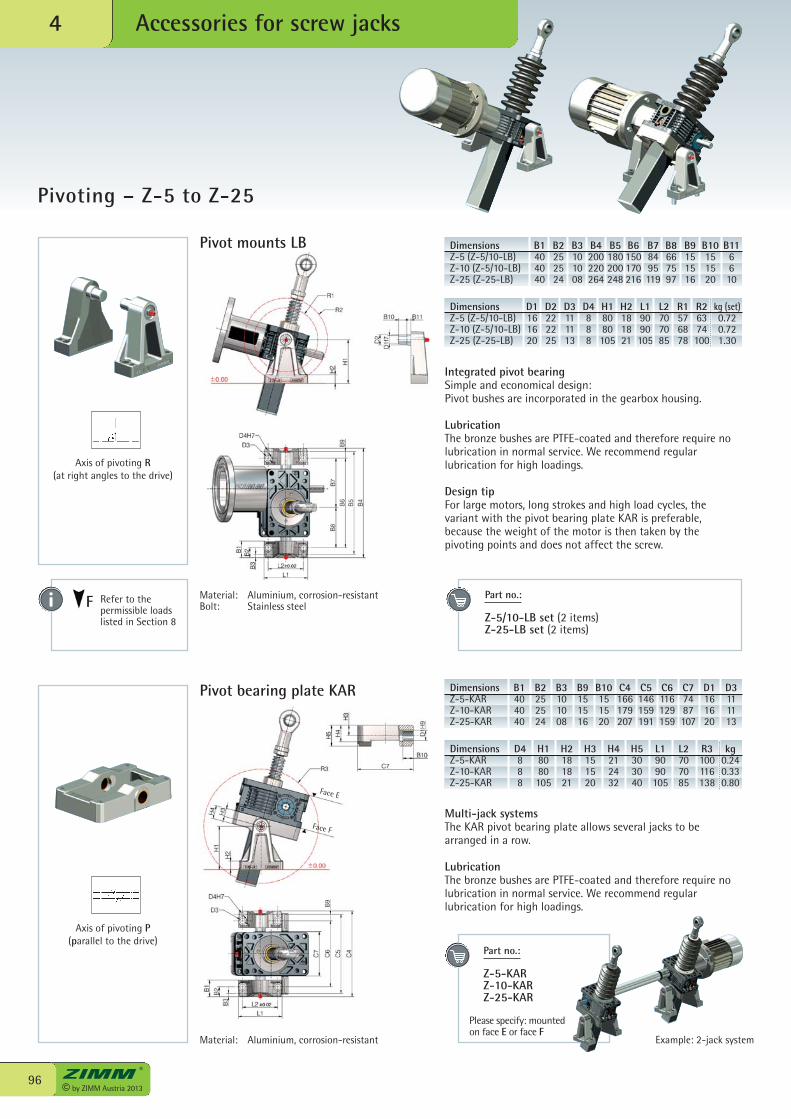
© by ZIMM Austria 201396
Accessories for screw jacks4
Pivoting – Z-5 to Z-25
Integrated pivot bearingSimple and economical design:Pivot bushes are incorporated in the gearbox housing.
LubricationThe bronze bushes are PTFE-coated and therefore require nolubrication in normal service. We recommend regularlubrication for high loadings.
Design tipFor large motors, long strokes and high load cycles, thevariant with the pivot bearing plate KAR is preferable,because the weight of the motor is then taken by the pivoting points and does not affect the screw.
DimensionsZ-5 (Z-5/10-LB)Z-10 (Z-5/10-LB)Z-25 (Z-25-LB)
B1404040
B2252524
B3101008
B4200220264
B5180200248
B6150170216
B78495119
B8667597
B9151516
B10151520
B116610
DimensionsZ-5 (Z-5/10-LB)Z-10 (Z-5/10-LB)Z-25 (Z-25-LB)
D1161620
D2222225
D3111113
D4888
H18080105
H2181821
L19090105
L2707085
R1576878
R26374100
kg (set)0.720.721.30
Axis of pivoting R(at right angles to the drive)
Pivot mounts LB
Pivot bearing plate KAR DimensionsZ-5-KARZ-10-KARZ-25-KAR
B1404040
B2252524
B3101008
B9151516
B10151520
C4166179207
C5146159191
C6116129159
C77487107
D1161620
D3111113
DimensionsZ-5-KARZ-10-KARZ-25-KAR
D4888
H18080105
H2181821
H3151520
H4212432
H5303040
L19090105
L2707085
R3100116138
kg0.240.330.80
Part no.: Z-5/10-LB set (2 items)Z-25-LB set (2 items)
Part no.:
Z-5-KARZ-10-KARZ-25-KAR
Multi-jack systemsThe KAR pivot bearing plate allows several jacks to bearranged in a row.
LubricationThe bronze bushes are PTFE-coated and therefore require nolubrication in normal service. We recommend regularlubrication for high loadings.
Axis of pivoting P(parallel to the drive)
Material: Aluminium, corrosion-resistantBolt: Stainless steel
Face E
Face F
Material: Aluminium, corrosion-resistant
Please specify: mountedon face E or face F
Example: 2-jack system
Refer to thepermissible loadslisted in Section 8
F
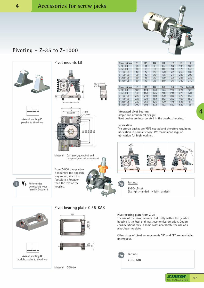
97© by ZIMM Austria 2013
Accessories for screw jacks
4
4
Pivot mounts LB
Pivoting – Z-35 to Z-1000
DimensionsZ-35-LBZ-50-LBZ-100-LBZ-150-LBZ-250-LBZ-350-LB
D1283040506080
D3111322222633
D481020202025
H185110120135170 210
H2181822243236
L1130170260280285380
L2106140180200230310
Axis of pivoting P(parallel to the drive)
DimensionsZ-35-LBZ-50-LBZ-100-LBZ-150-LBZ-250-LBZ-350-LB
L3106140225235220300
B1124150210222265302
B2146175250262325372
B3174210290312400462
B4202245330362475552
B5224270370402535622
kg (set)3.25.011.818.03166
Pivot bearing plate Z-35-KAR
Axis of pivoting R(at right angles to the drive)
Material: Cast steel, quenched and tempered, corrosion-resistant
Refer to thepermissible loadslisted in Section 8
F
Integrated pivot bearingSimple and economical design:Pivot bushes are incorporated in the gearbox housing.
LubricationThe bronze bushes are PTFE-coated and therefore require nolubrication in normal service. We recommend regularlubrication for high loadings.
From Z-500 the gearboxis mounted the oppositeway round, since thefootplate is broaderthan the rest of thehousing:
Pivot bearing plate from Z-35The use of the pivot mounts LB directly within the gearboxhousing is the best and most economical solution. Designconsiderations may in some cases necessitate the use of apivot bearing plate.
Other sizes of pivot arrangements “R” and “P” are availableon request.
Part no.:
Z-50-LB set(1x right-handed, 1x left-handed)
Part no.: Z-35-KAR
Material: GGG-50
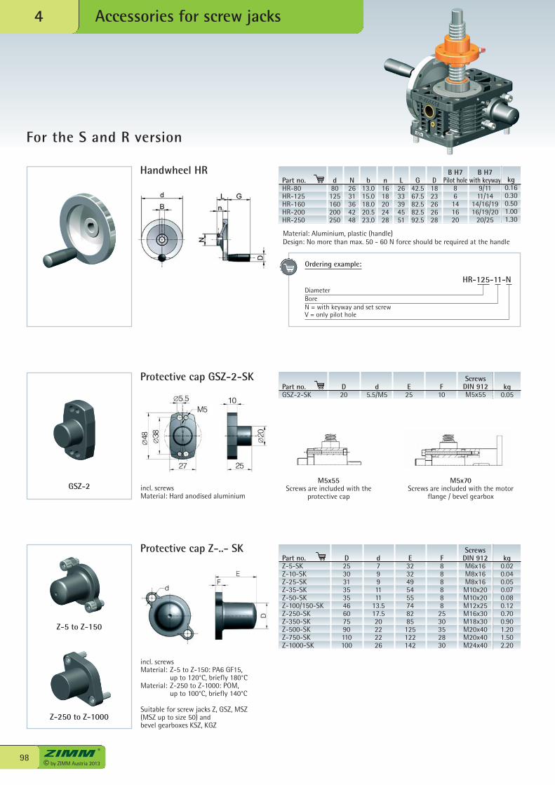
© by ZIMM Austria 201398
Accessories for screw jacks4
For the S and R version
Handwheel HRPart no.HR-80HR-125HR-160HR-200HR-250
d80125160200250
N2631364248
b13.015.018.020.523.0
n1618202428
L2633394551
G42.567.582.582.592.5
D1823262628
B H7Pilot hole
86141620
B H7with keyway
9/1111/14
14/16/1916/19/20
20/25
kg0.160.300.501.001.30
Protective cap GSZ-2-SK
Protective cap Z-..- SK
incl. screwsMaterial: Hard anodised aluminium
M5x55Screws are included with the
protective cap
M5x70Screws are included with the motor
flange / bevel gearbox
incl. screwsMaterial: Z-5 to Z-150: PA6 GF15, up to 120°C, briefly 180°CMaterial: Z-250 to Z-1000: POM, up to 100°C, briefly 140°C
Suitable for screw jacks Z, GSZ, MSZ (MSZ up to size 50) and bevel gearboxes KSZ, KGZ
Z-5 to Z-150
GSZ-2
Z-250 to Z-1000
Part no.Z-5-SKZ-10-SKZ-25-SKZ-35-SKZ-50-SKZ-100/150-SKZ-250-SKZ-350-SKZ-500-SKZ-750-SKZ-1000-SK
D253031353546607590110100
d7991111
13.517.520222226
E3232495455748285125122142
F8888882530352830
ScrewsDIN 912M6x16M8x16M8x16M10x20M10x20M12x25M16x30M18x30M20x40M20x40M24x40
kg0.020.040.050.070.080.120.700.901.201.502.20
Part no.GSZ-2-SK
D20
d5.5/M5
E25
F10
ScrewsDIN 912M5x55
kg0.05
Ordering example:
HR-125-11-NDiameterBoreN = with keyway and set screwV = only pilot hole
Material: Aluminium, plastic (handle)Design: No more than max. 50 - 60 N force should be required at the handle
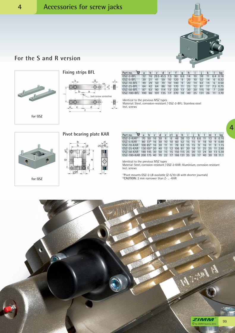
99© by ZIMM Austria 2013
Accessories for screw jacks
4
For the S and R version
4
Fixing strips BFL Part no.GSZ-2-BFLGSZ-5-BFLGSZ-10-BFLGSZ-25-BFLGSZ-50-BFLGSZ-100-BFL
a3239496487100
b162129426366
c29.541506490101
d45.5597086114135
e7.51010101317
f90120140170230270
g6.699111318
h142020253040
i101014122025
j38526381115131
k111414171926
l6.466
7.5711
kg0.160.320.500.752.003.70
Identical to the previous MSZ typesMaterial: Steel, corrosion-resistant / GSZ-2-BFL: Stainless steelIncl. screws
Pivot bearing plate KAR Part no.GSZ-2-KAR1)
GSZ-5-KARGSZ-10-KARGSZ-25-KARGSZ-50-KARGSZ-100-KAR
a7080100130180200
c161616203040
d303030405070
e61011121522
e161011121517
g486078106150166
h38526381115131
i131515202535
j131515182026
k6.699111317
l111816252440
m131011253030
t899111318
kg0.160.801.152.805.3011.1
Identical to the previous MSZ typesMaterial: Steel, corrosion-resistant / GSZ-2-KAR: Aluminium, corrosion-resistantIncl. screws
1)Pivot mounts GSZ-2-LB available (Z-5/10-LB with shorter journals)2)CAUTION: 2 mm narrower than Z- .. -KAR
Jack screw centreline
for GSZ
for GSZ
b50722)
852)
1052)
145175
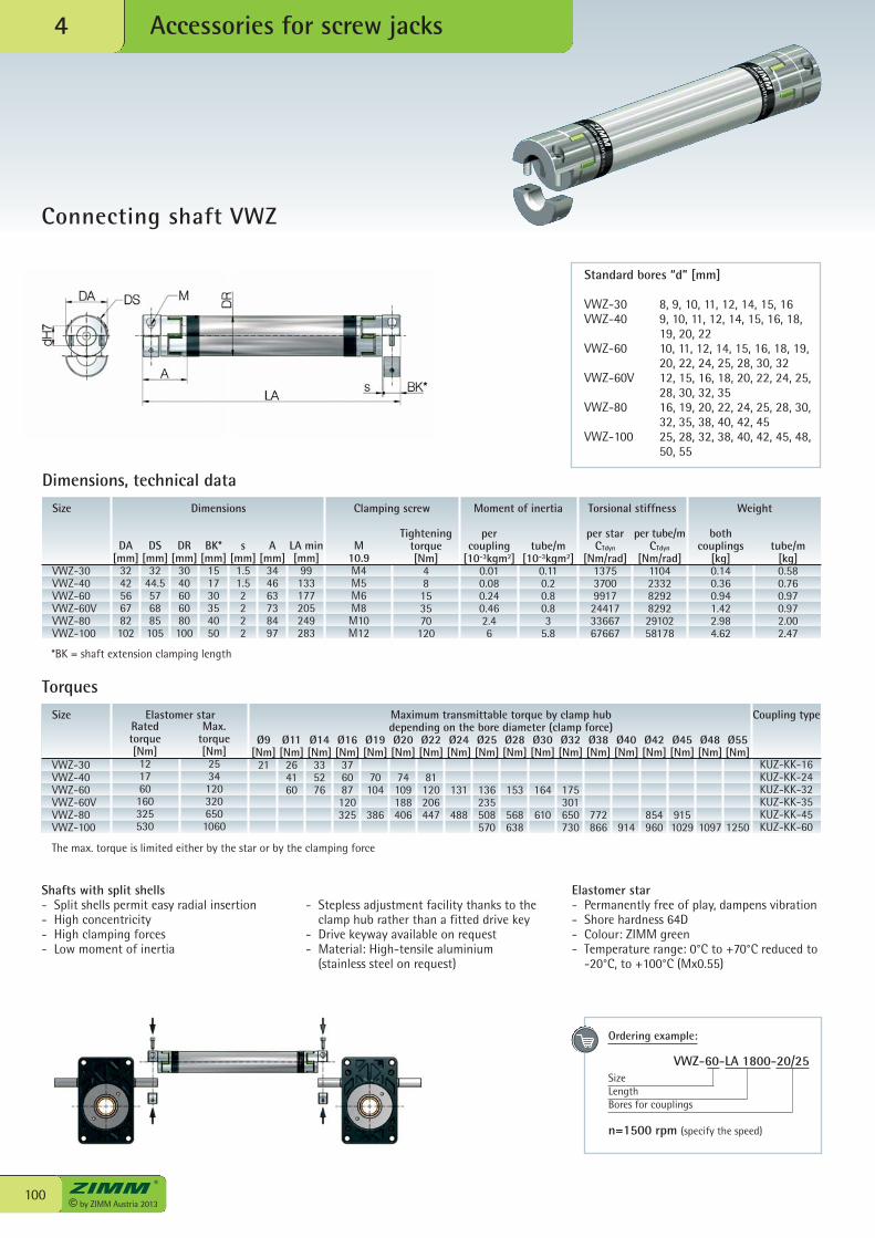
© by ZIMM Austria 2013100
Accessories for screw jacks4
Connecting shaft VWZ
Size
VWZ-30VWZ-40VWZ-60VWZ-60VVWZ-80VWZ-100
Dimensions Clamping screw Moment of inertia Torsional stiffness Weight
DA[ mm]
3242566782102
DS[ mm]
3244.5576885105
DR[ mm]
3040606080100
BK*[ mm]
151730354050
s[ mm]1.51.52222
A[ mm]
344663738497
LA min[ mm]
99133177205249283
M10.9M4M5M6M8M10M12
Tighteningtorque [ Nm]
48153570
120
per coupling
[10-3kgm2]0.010.080.240.462.46
per starCTdyn
[Nm/rad]137537009917244173366767667
per tube/mCTdyn
[Nm/rad]11042332829282922910258178
bothcouplings
[kg]0.140.360.941.422.984.62
tube/m [10-3kgm2]
0.110.20.80.83
5.8
Dimensions, technical data
tube/m[kg]0.580.760.970.972.002.47
Size
VWZ-30VWZ-40VWZ-60VWZ-60VVWZ-80VWZ-100
Elastomer star Maximum transmittable torque by clamp hubdepending on the bore diameter (clamp force)
Coupling typeRated torque[ Nm]
121760160325530
Max. torque[ Nm]
25341203206501060
Ø9[ Nm]
21
Torques
Ø11[ Nm]
264160
Ø14[ Nm]
335276
Ø16[ Nm]
376087120325
Ø19[ Nm]
70104
386
Ø20[ Nm]
74109188406
Ø22[ Nm]
81120206447
Ø24[ Nm]
131
488
Ø25[ Nm]
136235508570
Ø28[ Nm]
153
568638
Ø30[ Nm]
164
610
Ø32[ Nm]
175301650730
Ø38[ Nm]
772866
Ø40[ Nm]
914
Ø42[ Nm]
854960
Ø45[ Nm]
9151029
Ø48[ Nm]
1097
Ø55[ Nm]
1250
KUZ-KK-16KUZ-KK-24KUZ-KK-32KUZ-KK-35KUZ-KK-45KUZ-KK-60
*BK = shaft extension clamping length
Standard bores “d” [mm]
VWZ-30 8, 9, 10, 11, 12, 14, 15, 16VWZ-40 9, 10, 11, 12, 14, 15, 16, 18, 19, 20, 22VWZ-60 10, 11, 12, 14, 15, 16, 18, 19, 20, 22, 24, 25, 28, 30, 32VWZ-60V 12, 15, 16, 18, 20, 22, 24, 25, 28, 30, 32, 35VWZ-80 16, 19, 20, 22, 24, 25, 28, 30, 32, 35, 38, 40, 42, 45VWZ-100 25, 28, 32, 38, 40, 42, 45, 48, 50, 55
Ordering example:
VWZ-60-LA 1800-20/25SizeLengthBores for couplings
n=1500 rpm (specify the speed)
Shafts with split shells- Split shells permit easy radial insertion- High concentricity- High clamping forces- Low moment of inertia
- Stepless adjustment facility thanks to theclamp hub rather than a fitted drive key
- Drive keyway available on request- Material: High-tensile aluminium
(stainless steel on request)
Elastomer star- Permanently free of play, dampens vibration- Shore hardness 64D- Colour: ZIMM green- Temperature range: 0°C to +70°C reduced to
-20°C, to +100°C (Mx0.55)
The max. torque is limited either by the star or by the clamping force
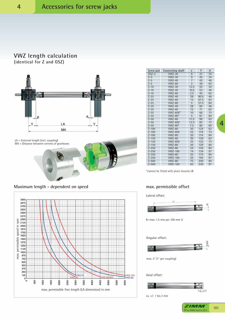
101© by ZIMM Austria 2013
Accessories for screw jacks
VWZ length calculation(identical for Z and GSZ)
4
max. permissible free length (LA dimension) in mm
max
. per
mis
sibl
e sp
eed
in r
pm
Maximum length - dependent on speed max. permissible offset
Screw jack Connecting shaft e Y A31454338555345
80.567.557.584716661908580124119114130125120144134175165240230
6972
12.510.52.5281552815105
17.512.57.5302520302520241435257565
VWZ-30VWZ-30VWZ-40VWZ-60VWZ-30VWZ-40VWZ-60VWZ-40VWZ-60VWZ-80VWZ-40VWZ-60VWZ-60V*VWZ-80*VWZ-60VWZ-60VVWZ-80*VWZ-60VWZ-60VVWZ-80VWZ-60VWZ-60VVWZ-80VWZ-80VWZ-100VWZ-80VWZ-100VWZ-80VWZ-100
GSZ-2Z-5Z-5Z-5Z-10Z-10Z-10Z-25Z-25Z-25Z-35Z-35Z-35Z-35Z-50Z-50Z-50Z-100Z-100Z-100Z-150Z-150Z-150Z-250Z-250Z-350Z-350Z-500Z-500
3434466334466346638446637384637384637384637384849784978497
*cannot be fitted with pivot mounts LB
LA = External length (incl. coupling)MA = Distance between centres of gearboxes
Lateral offset:
Kr max. 1.5 mm per 100 mm LI
Angular offset:
max. 2° (1° per coupling)
Axial offset:
ca. +/- 1 bis 2 mm
4
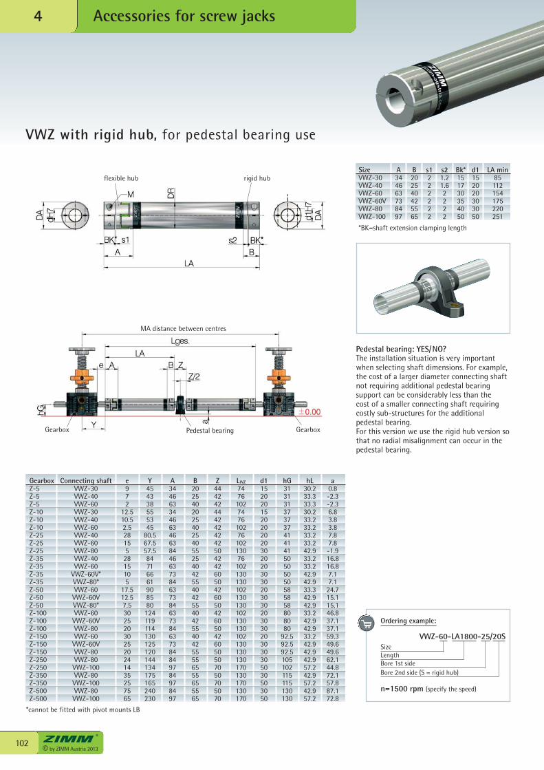
© by ZIMM Austria 2013102
Accessories for screw jacks4
VWZ with rigid hub, for pedestal bearing use
flexible hub rigid hubSize A B s1 s2 Bk* d1 LA minVWZ-30 34 20 2 1.2 15 15 85VWZ-40 46 25 2 1.6 17 20 112VWZ-60 63 40 2 2 30 20 154VWZ-60V 73 42 2 2 35 30 175VWZ-80 84 55 2 2 40 30 220VWZ-100 97 65 2 2 50 50 251
Gearbox GearboxPedestal bearing
MA distance between centres
Pedestal bearing: YES/NO?The installation situation is very importantwhen selecting shaft dimensions. For example,the cost of a larger diameter connecting shaftnot requiring additional pedestal bearingsupport can be considerably less than thecost of a smaller connecting shaft requiringcostly sub-structures for the additionalpedestal bearing.For this version we use the rigid hub version sothat no radial misalignment can occur in thepedestal bearing.
Gearbox Connecting shaft e Y A B Z LWZ d1 hG hL aZ-5 VWZ-30 9 45 34 20 44 74 15 31 30.2 0.8Z-5 VWZ-40 7 43 46 25 42 76 20 31 33.3 -2.3Z-5 VWZ-60 2 38 63 40 42 102 20 31 33.3 -2.3Z-10 VWZ-30 12.5 55 34 20 44 74 15 37 30.2 6.8Z-10 VWZ-40 10.5 53 46 25 42 76 20 37 33.2 3.8Z-10 VWZ-60 2.5 45 63 40 42 102 20 37 33.2 3.8Z-25 VWZ-40 28 80.5 46 25 42 76 20 41 33.2 7.8Z-25 VWZ-60 15 67.5 63 40 42 102 20 41 33.2 7.8Z-25 VWZ-80 5 57.5 84 55 50 130 30 41 42.9 -1.9Z-35 VWZ-40 28 84 46 25 42 76 20 50 33.2 16.8Z-35 VWZ-60 15 71 63 40 42 102 20 50 33.2 16.8Z-35 VWZ-60V* 10 66 73 42 60 130 30 50 42.9 7.1Z-35 VWZ-80* 5 61 84 55 50 130 30 50 42.9 7.1Z-50 VWZ-60 17.5 90 63 40 42 102 20 58 33.3 24.7Z-50 VWZ-60V 12.5 85 73 42 60 130 30 58 42.9 15.1Z-50 VWZ-80* 7.5 80 84 55 50 130 30 58 42.9 15.1Z-100 VWZ-60 30 124 63 40 42 102 20 80 33.2 46.8Z-100 VWZ-60V 25 119 73 42 60 130 30 80 42.9 37.1Z-100 VWZ-80 20 114 84 55 50 130 30 80 42.9 37.1Z-150 VWZ-60 30 130 63 40 42 102 20 92.5 33.2 59.3Z-150 VWZ-60V 25 125 73 42 60 130 30 92.5 42.9 49.6Z-150 VWZ-80 20 120 84 55 50 130 30 92.5 42.9 49.6Z-250 VWZ-80 24 144 84 55 50 130 30 105 42.9 62.1Z-250 VWZ-100 14 134 97 65 70 170 50 102 57.2 44.8Z-350 VWZ-80 35 175 84 55 50 130 30 115 42.9 72.1Z-350 VWZ-100 25 165 97 65 70 170 50 115 57.2 57.8Z-500 VWZ-80 75 240 84 55 50 130 30 130 42.9 87.1Z-500 VWZ-100 65 230 97 65 70 170 50 130 57.2 72.8
*cannot be fitted with pivot mounts LB
Ordering example:
VWZ-60-LA1800-25/20S SizeLengthBore 1st sideBore 2nd side (S = rigid hub)
n=1500 rpm (specify the speed)
*BK=shaft extension clamping length
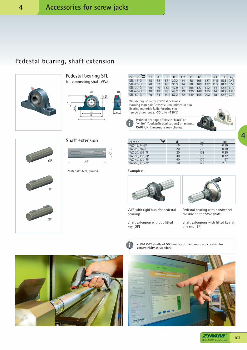
103© by ZIMM Austria 2013
Accessories for screw jacks
Pedestal bearing, shaft extension
4
4
Part no.WZ-15/74-?PWZ-20/76-?PWZ-20/102-?PWZ-30/130-?PWZ-40/170-?PWZ-50/170-?P
d1152020304050
LWZ
7476102130170170
kg0.100.190.250.721.672.61
Pedestal bearing STL for connecting shaft VWZ
Shaft extension
Examples:
Part no. d1 A H H1 H2 J1 J2 L N1 S1 kgSTL-15-G 15 32 56 30.2 14 88 106 127 11.5 15.3 0.47STL-20-G 20 32 65 33.3 14 88 106 127 11.5 18.3 0.59STL-30-G 30 40 82.5 42.9 17 108 127 152 14 22.2 1.10STL-40-G 40 48 99 49.2 19 125 146 175 14 30.2 1.85STL-50-G 50 54 114.5 57.2 22 149 165 203 18 32.6 2.70
Material: Steel, ground
We use high-quality pedestal bearings.Housing material: Grey cast iron, primed in blueBearing material: Roller bearing steelTemperature range: -30°C to +120°C
0P
1P
2P
VWZ with rigid hub, for pedestalbearings
Shaft extension without fittedkey (OP)
Pedestal bearing with handwheelfor driving the VWZ shaft
Shaft extensions with fitted key atone end (1P)
Pedestal bearings of plastic “black” or“white” (foodstuffs applications) on request. CAUTION: Dimensions may change!
ZIMM VWZ shafts of 500 mm length and more are checked forconcentricity as standard!
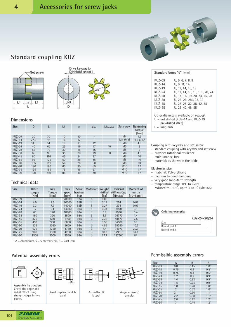
© by ZIMM Austria 2013104
Accessories for screw jacks4
Standard coupling KUZ
Potential assembly errors
Coupling with keyway and set screw- standard coupling with keyway and set screw- provides rotational resilience- maintenance-free- material: as shown in the table
Elastomer star- material: Polyurethane- medium to good damping- very good long-term strength- temperature range: 0°C to +70°C reduced to -30°C, up to +100°C (Mx0.55)
Standard bores “d” [mm]
KUZ-09 U, 5, 6, 7, 8, 9KUZ-14 U, 9, 11, 14KUZ-19 U, 11, 14, 16, 19KUZ-24 U, 11, 14, 16, 19, 19L, 20, 24KUZ-28 U, 14, 16, 19, 20, 24, 25, 28KUZ-38 U, 25, 28, 28L, 32, 38KUZ-45 U, 25, 28, 32, 38, 42, 45KUZ-55 U, 28, 42, 48, 55
Other diameters available on requestU = not drilled (KUZ-14 and KUZ-19
pre-drilled Ø6.3)L = long hub
Technical dataSize
KUZ-09KUZ-14KUZ-19KUZ-24KUZ-28KUZ-38KUZ-45KUZ-55KUZ-60KUZ-70KUZ-75KUZ-90
Ratedtorque[ Nm]
34.57.317601603254505256259001500
max.Torque[ Nm]
64.57.3341203206509001050125013003000
max.speed[ rpm]28000200001400014000106008500710060005600475042503550
Shorehardness
Star92A55D55D98A98A98A98A 98A98A98A 98A98A
Material*
ASSSSSGGGGGG
Weight,drilled[ kg]0.050.140.270.340.91.52.353.554.857.410.817.7
Torsionalstiffness CTdyn
[Nm/rad]
254274292099302677048570545006529094970129510197500
Moment ofinertia
[10-3kgm2]
0.020.030.10.41.42.56.110.220.337.184
* A = Aluminium, S = Sintered steel, G = Cast iron
Dimensions
Assembly instruction:Check the angle andradial offset usingstraight edges in twoplanes
Axial displacement Aaxial
Axis offset Rlateral
Angular error βangular
SizeKUZ-09KUZ-14KUZ-19KUZ-24KUZ-28KUZ-38KUZ-45KUZ-55KUZ-60KUZ-70KUZ-75KUZ-90
A0.80.750.751.21.41.51.82
2.12.22.63
R0.150.40.40.20.220.250.280.320.360.380.420.48
β1.0°0.5°0.5°0.9°0.9°0.9°1.0°1.0°1.1°1.1°1.2°1.2°
Permissible assembly errors
Ordering example:
KUZ-24-20/24 SizeBore d end 1Bore d end 2
Size
KUZ-09KUZ-14KUZ-19KUZ-24KUZ-28KUZ-38KUZ-45KUZ-55KUZ-60KUZ-70KUZ-75KUZ-90
D
2027.534.54055658095105120135160
L
304451667890114126140160185210
L1
101619253035455056657585
a
101213161820242628303540
dstar
--
12172629374550596779
L1long hub
40
60
Set screw
M4M6 (M4)
M6M5M5M6M8M8M8M10M10M10
Tighteningtorque[Nm]1.5
4.8 (1.5)4.822
4.8101010171717
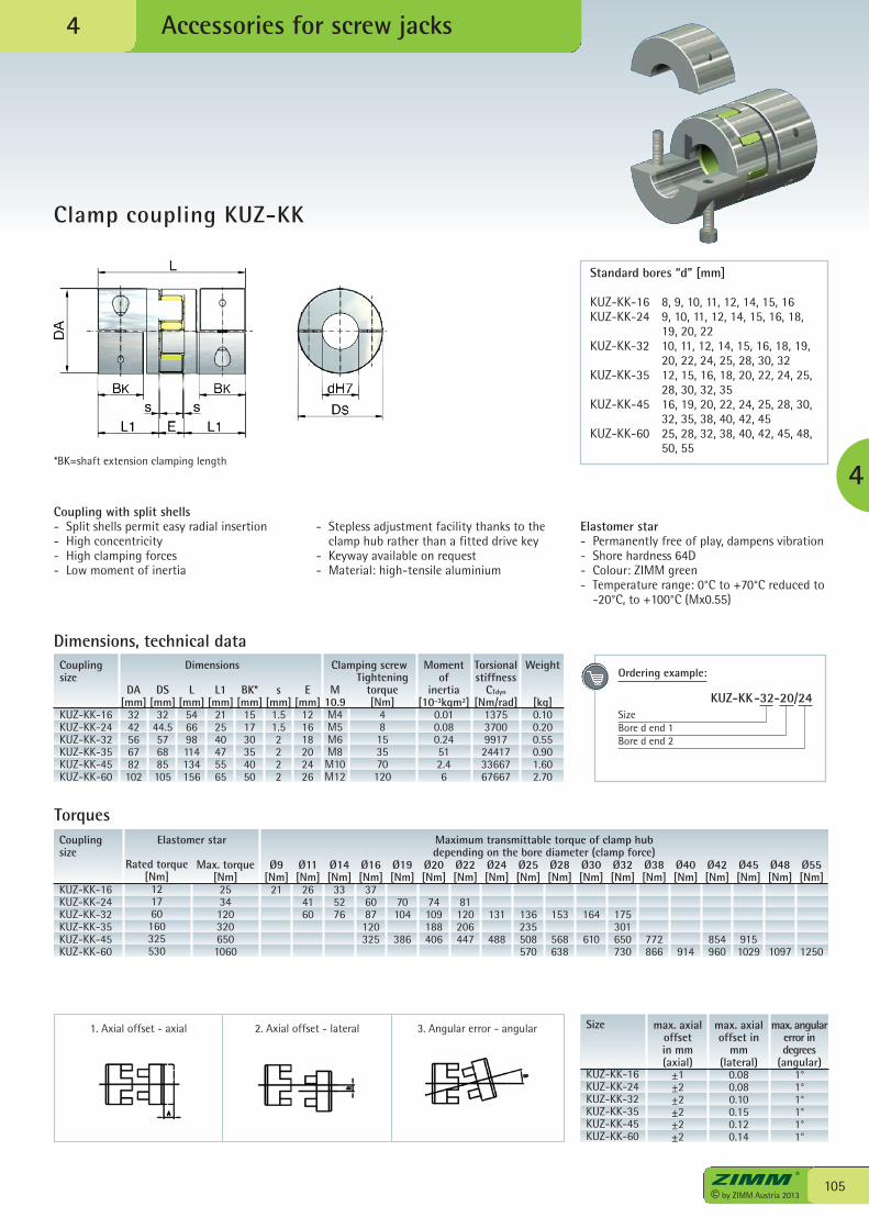
Ordering example:
KUZ-KK-32-20/24SizeBore d end 1Bore d end 2
Accessories for screw jacks
105© by ZIMM Austria 2013
Clamp coupling KUZ-KK
4*BK=shaft extension clamping length
Size
KUZ-KK-16KUZ-KK-24KUZ-KK-32KUZ-KK-35KUZ-KK-45KUZ-KK-60
max. axialoffset in mm(axial)
±1±2±2±2±2±2
max. axialoffset in
mm(lateral)
0.080.080.100.150.120.14
max. angularerror indegrees
(angular)1°1°1°1°1°1°
Standard bores “d” [mm]
KUZ-KK-16 8, 9, 10, 11, 12, 14, 15, 16KUZ-KK-24 9, 10, 11, 12, 14, 15, 16, 18, 19, 20, 22KUZ-KK-32 10, 11, 12, 14, 15, 16, 18, 19,
20, 22, 24, 25, 28, 30, 32KUZ-KK-35 12, 15, 16, 18, 20, 22, 24, 25,
28, 30, 32, 35KUZ-KK-45 16, 19, 20, 22, 24, 25, 28, 30,
32, 35, 38, 40, 42, 45KUZ-KK-60 25, 28, 32, 38, 40, 42, 45, 48,
50, 55
Dimensions, technical dataCouplingsize
KUZ-KK-16KUZ-KK-24KUZ-KK-32KUZ-KK-35KUZ-KK-45KUZ-KK-60
Tighteningtorque[ Nm]
48153570
120
M10.9M4M5M6M8M10M12
DA[ mm]
3242566782102
DS[ mm]
3244.5576885105
L[ mm]
546698114134156
L1[ mm]
212540475565
BK*[ mm]
151730354050
s[ mm]1.51.52222
E[ mm]
121618202426
Clamping screwDimensions Weight
[ kg]0.100.200.550.901.602.70
Torsionalstiffness
CTdyn
[Nm/rad]137537009917244173366767667
Moment of
inertia[10-3kgm2]
0.010.080.24512.46
1. Axial offset - axial 2. Axial offset - lateral 3. Angular error - angular
4
Coupling size
KUZ-KK-16KUZ-KK-24KUZ-KK-32KUZ-KK-35KUZ-KK-45KUZ-KK-60
Elastomer star Maximum transmittable torque of clamp hubdepending on the bore diameter (clamp force)
Rated torque[ Nm]
121760160325530
Max. torque[ Nm]
25341203206501060
Ø9[ Nm]
21
Torques
Ø11[ Nm]
264160
Ø14[ Nm]
335276
Ø16[ Nm]
376087120325
Ø19[ Nm]
70104
386
Ø20[ Nm]
74109188406
Ø22[ Nm]
81120206447
Ø24[ Nm]
131
488
Ø25[ Nm]
136235508570
Ø28[ Nm]
153
568638
Ø30[ Nm]
164
610
Ø32[ Nm]
175301650730
Ø38[ Nm]
772866
Ø40[ Nm]
914
Ø42[ Nm]
854960
Ø45[ Nm]
9151029
Ø48[ Nm]
1097
Ø55[ Nm]
1250
Coupling with split shells- Split shells permit easy radial insertion- High concentricity- High clamping forces- Low moment of inertia
- Stepless adjustment facility thanks to theclamp hub rather than a fitted drive key
- Keyway available on request- Material: high-tensile aluminium
Elastomer star- Permanently free of play, dampens vibration- Shore hardness 64D- Colour: ZIMM green- Temperature range: 0°C to +70°C reduced to
-20°C, to +100°C (Mx0.55)
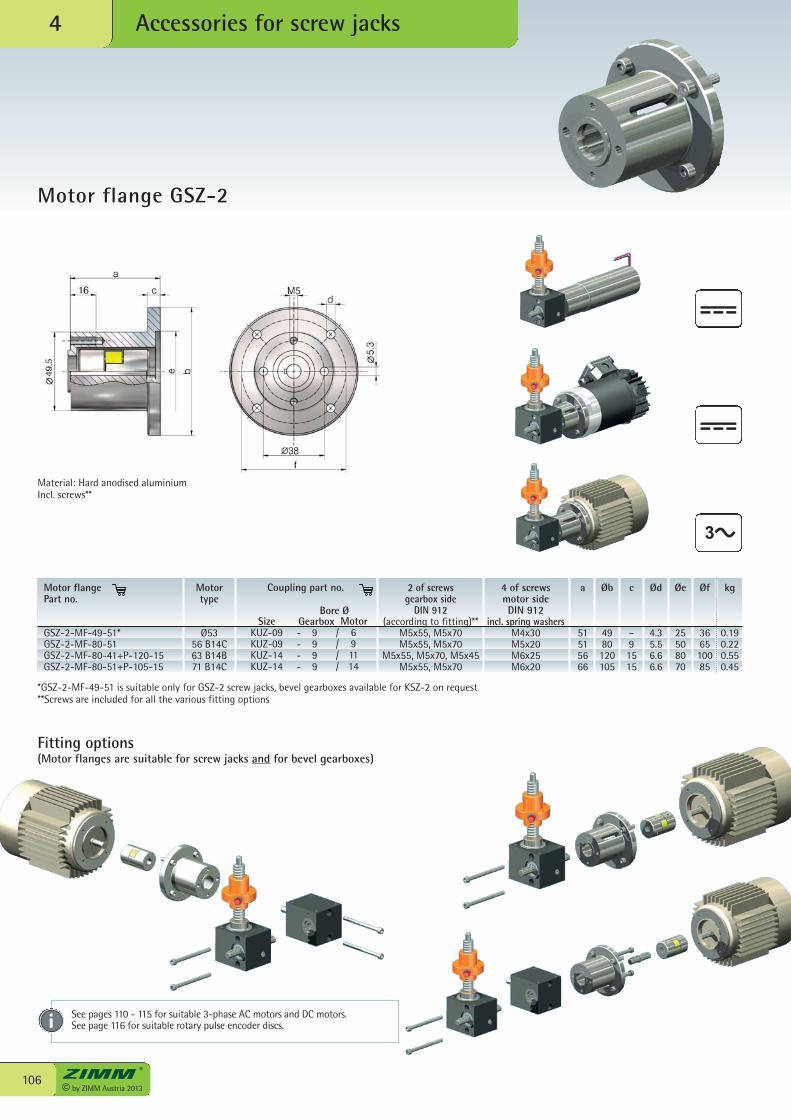
© by ZIMM Austria 2013106
Accessories for screw jacks4
Motor flange GSZ-2
Motor type
Ø5356 B14C63 B14B71 B14C
2 of screws gearbox side
DIN 912(according to fitting)**
M5x55, M5x70M5x55, M5x70
M5x55, M5x70, M5x45M5x55, M5x70
4 of screws motor sideDIN 912
incl. spring washersM4x30M5x20M6x25M6x20
a
51515666
Øb
4980120105
c
–91515
Ød
4.35.56.66.6
Øe
25508070
Øf
366510085
kg
0.190.220.550.45
Motor flangePart no.
GSZ-2-MF-49-51*GSZ-2-MF-80-51GSZ-2-MF-80-41+P-120-15GSZ-2-MF-80-51+P-105-15
*GSZ-2-MF-49-51 is suitable only for GSZ-2 screw jacks, bevel gearboxes available for KSZ-2 on request**Screws are included for all the various fitting options
See pages 110 - 115 for suitable 3-phase AC motors and DC motors.See page 116 for suitable rotary pulse encoder discs.
Fitting options(Motor flanges are suitable for screw jacks and for bevel gearboxes)
Material: Hard anodised aluminiumIncl. screws**
Coupling part no.
SizeKUZ-09KUZ-09KUZ-14KUZ-14
Gearbox- 9- 9- 9- 9
Motor/ 6/ 9/ 11/ 14
Bore Ø
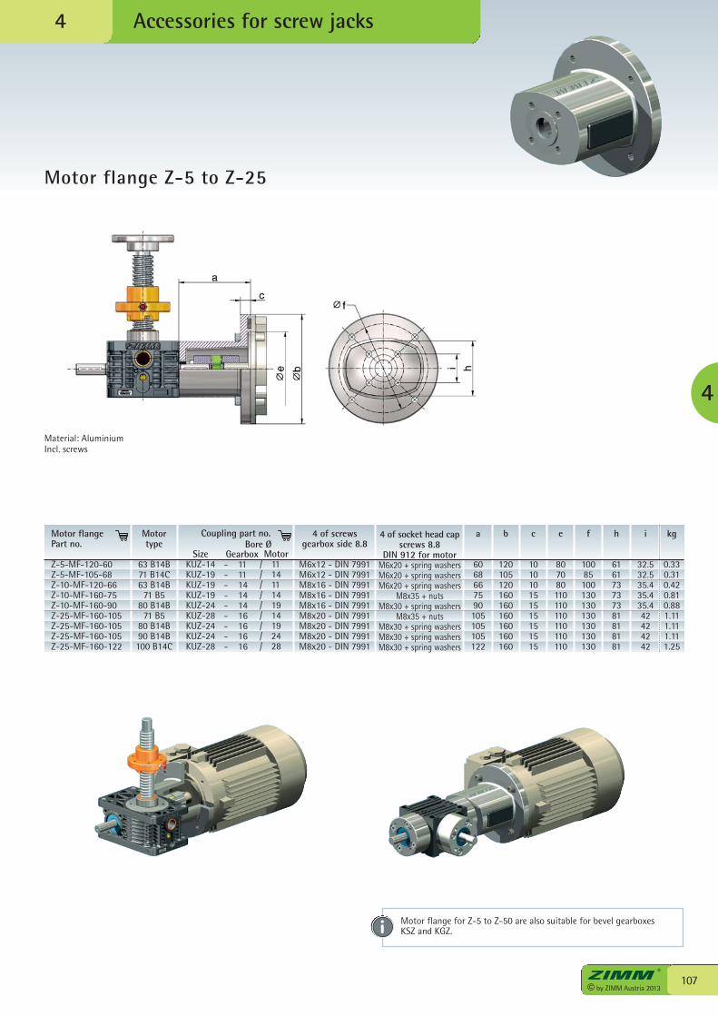
107© by ZIMM Austria 2013
Accessories for screw jacks
Motor flange Z-5 to Z-25
4
4
Motortype
63 B14B71 B14C63 B14B
71 B580 B14B
71 B580 B14B90 B14B100 B14C
SizeKUZ-14KUZ-19KUZ-19KUZ-19KUZ-24KUZ-28KUZ-24KUZ-24KUZ-28
4 of screws gearbox side 8.8
M6x12 - DIN 7991M6x12 - DIN 7991M8x16 - DIN 7991M8x16 - DIN 7991M8x16 - DIN 7991M8x20 - DIN 7991M8x20 - DIN 7991M8x20 - DIN 7991M8x20 - DIN 7991
4 of socket head capscrews 8.8
DIN 912 for motorM6x20 + spring washersM6x20 + spring washersM6x20 + spring washers
M8x35 + nutsM8x30 + spring washers
M8x35 + nutsM8x30 + spring washersM8x30 + spring washersM8x30 + spring washers
a
6068667590105105105122
b
120105120160160160160160160
c
101010151515151515
e
807080110110110110110110
f
10085100130130130130130130
h
616173737381818181
i
32.532.535.435.435.442424242
kg
0.330.310.420.810.881.111.111.111.25
Gearbox- 11- 11- 14- 14- 14- 16- 16- 16- 16
Motor/ 11/ 14/ 11/ 14/ 19/ 14/ 19/ 24/ 28
Coupling part no.Bore Ø
Motor flangePart no.
Z-5-MF-120-60Z-5-MF-105-68Z-10-MF-120-66Z-10-MF-160-75Z-10-MF-160-90Z-25-MF-160-105Z-25-MF-160-105Z-25-MF-160-105Z-25-MF-160-122
Material: AluminiumIncl. screws
Motor flange for Z-5 to Z-50 are also suitable for bevel gearboxes KSZ and KGZ.
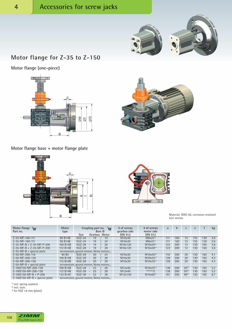
4 of screwsgearbox side
DIN 912M10x30M10x30M10x120M10x120
M10x30M10x30M10x30
M12x40M12x40M12x150
4 of screwsmotor sideDIN 912M8x251)
M8x251)
M10x301)
M10x301)
M10x452)
M10x351)
M10x351)
M10x351)
M10x351)M10x651)
a
111111123123
116126126
138138161
b
160160200200
200200200
200200200
c
15151212
202020
203)
203)
483)
e
110110130130
130130130
130130130
f
130130165165
165165165
165165165
kg
2.62.63.63.6
4.14.34.3
5.25.28.7
Motor flangePart no.
Z-35-MF-160-111Z-35-MF-160-111Z-35-MF-B + Z-35-MF-P-200Z-35-MF-B + Z-35-MF-P-200Z-35-MF-B + special plate servomotors, geared motors, Nema motors,...Z-50-MF-200-116Z-50-MF-200-126Z-50-MF-200-126Z-50-MF-B + special plate servomotors, geared motors, Nema motors,...Z-100/150-MF-200-138Z-100/150-MF-200-138Z-100/150-MF-B + P-200Z-100/150-MF-B + special plate servomotors, geared motors, Nema motors,...
Bore ØSize
KUZ-24KUZ-24KUZ-28KUZ-28
KUZ-28KUZ-28KUZ-28
KUZ-28KUZ-28KUZ-38
Gearbox- 19- 19- 19- 19
- 20- 20- 20
- 25- 25- 25
Motortype
80 B14B90 B14B100 B14B112 B14B
90 B5100 B14B112 B14B
100 B14B112 B14B132 B14C
Motor/ 19/ 24/ 28/ 28
/ 24/ 28/ 28
/ 28/ 28/ 38
Coupling part no.
© by ZIMM Austria 2013108
Accessories for screw jacks4
Motor flange for Z-35 to Z-150
Motor flange (one-piece)
Motor flange base + motor flange plate
Material: GGG-50, corrosion-resistantIncl. screws
1) incl. spring washers2) incl. nuts3) for GSZ +6 mm (plate)
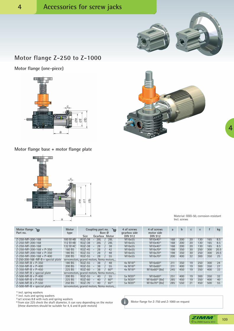
109© by ZIMM Austria 2013
Accessories for screw jacks
4
Motor flange Z-250 to Z-1000
4
Motor flange (one-piece)
Motor flange base + motor flange plate
Material: GGG-50, corrosion-resistantIncl. screws
4 of screwsgearbox side
DIN 912M16x55M16x55M16x55M16x55M16x55M16x55
4x M183)
4x M183)
4x M183)
5x M203)
5x M203)
5x M203)
4 of screws motor sideDIN 912M10x401)
M10x401)
M10x401)
M16x702)
M16x702)
M16x702)
M16x602)
M16x602)
M16x602) (8x)
M16x602)
M16x602) (8x)M16x702) (8x)
a
168168168198198200
211211245
251285285
b
200200200350350400
350400450
400450550
c
202020303032
191919
191921
e
130130130250250300
250300350
300350450
f
165165165300300350
300350400
350400500
kg
8.58.58.520.520.525
242733
324055
Motor flangePart no.
Z-250-MF-200-168Z-250-MF-200-168Z-250-MF-200-168Z-250-MF-200-168 + P-350Z-250-MF-200-168 + P-350Z-250-MF-200-168 + P-400Z-250-200-168 -MF-B + special plate servomotors, geared motors, Nema motors,...Z-350-MF-B + P-350Z-350-MF-B + P-400Z-350-MF-B + P-450Z-350-MF-B + special plate servomotors, geared motors, Nema motors,...Z-500-MF-B + P-400Z-500-MF-B + P-450Z-500-MF-B + P-550Z-500-MF-B + special plate servomotors, geared motors, Nema motors,...
Bore ØSize
KUZ-38KUZ-38KUZ-38KUZ-45KUZ-55KUZ-55
KUZ-55KUZ-55KUZ-60
KUZ-55KUZ-60KUZ-70
Gearbox- 28L- 28L- 28- 28- 28- 28
- 38- 38- 38
- 40- 40- 40
Motortype
100 B14B112 B14B132 B14C160 B5180 B5200 B5
180 B5200 B5225 B5
200 B5225 B5250 B5
Motor/ 28L/ 28L/ 38/ 42/ 48/ 55
/ 48/ 55/ 604)
/ 55/ 604)
/ 654)
Coupling part no.
Motor flange for Z-750 and Z-1000 on request
1) incl. spring washers 2) incl. nuts and spring washers 3) set screws 8.8 with nuts and spring washers4) from size 225 check the shaft diameter, it can vary depending on the motor (these diameters should be suitable for 4, 6 and 8-pole motors)
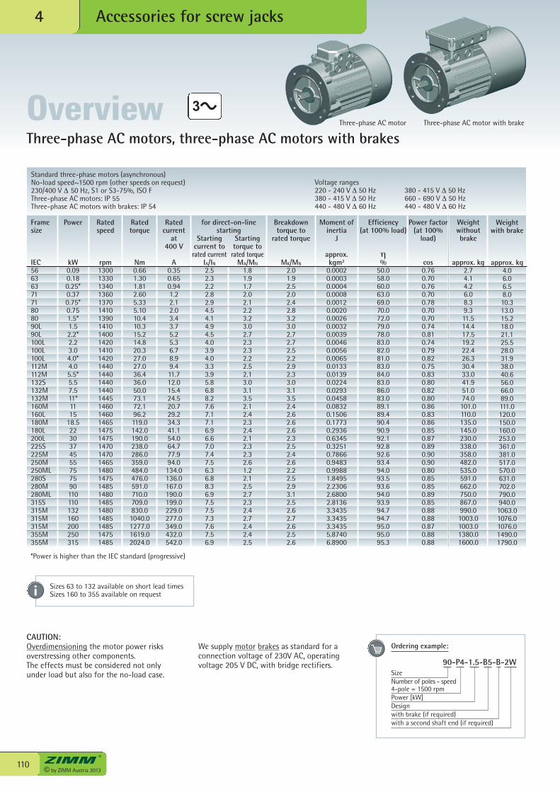
© by ZIMM Austria 2013110
Accessories for screw jacks4
Three-phase AC motors, three-phase AC motors with brakes
Standard three-phase motors (asynchronous)No-load speed~1500 rpm (other speeds on request)230/400 V Δ 50 Hz, S1 or S3-75%, ISO FThree-phase AC motors: IP 55Three-phase AC motors with brakes: IP 54
Voltage ranges220 - 240 V Δ 50 Hz380 - 415 V Δ 50 Hz440 - 480 V Δ 60 Hz
380 - 415 V Δ 50 Hz660 - 690 V Δ 50 Hz440 - 480 V Δ 60 Hz
CAUTION:Overdimensioning the motor power risksoverstressing other components.The effects must be considered not onlyunder load but also for the no-load case.
We supply motor brakes as standard for aconnection voltage of 230V AC, operatingvoltage 205 V DC, with bridge rectifiers.
Ratedspeed
rpm13001330134013601370141013901410140014201410142014401440144014401445146014601465147514751470147014651480147514851480148514801485148514751485
Rated torque
Nm0.661.301.812.605.335.1010.410.315.214.820.327.027.036.436.050.073.172.196.2119.0142.0190.0238.0286.0359.0484.0476.0591.0710.0709.0830.01040.01277.01619.02024.0
Ratedcurrent
at 400 V
A0.350.650.941.22.12.03.43.75.25.36.78.99.411.712.015.424.520.729.234.341.154.064.777.994.0134.0136.0167.0190.0199.0229.0277.0349.0432.0542.0
Breakdowntorque to
rated torque
MK/MN
2.01.92.52.02.42.83.23.02.72.72.52.22.92.33.03.13.52.42.62.62.62.32.52.42.62.22.52.93.12.52.62.72.62.52.6
Moment ofinertia
J
approx.kgm2
0.00020.00030.00040.00080.00120.00200.00260.00320.00390.00460.00560.00650.01330.01390.02240.02930.04580.08320.15060.17730.29360.63450.32510.78660.94830.99881.84952.23062.68002.81363.34353.34353.34355.87406.8900
Efficiency(at 100% load)
η%
50.058.060.063.069.070.072.079.078.083.082.081.083.084.083.086.083.089.189.490.490.992.192.892.693.494.093.593.694.093.994.794.795.095.095.3
Power factor(at 100%
load)
cos0.760.700.760.700.780.700.700.740.810.740.790.820.750.830.800.820.800.860.830.860.850.870.890.900.900.800.850.850.890.850.880.880.870.880.88
Weightwithoutbrake
approx. kg2.74.14.26.08.39.311.514.417.519.222.426.330.433.041.951.074.0101.0110.0135.0145.0230.0338.0358.0482.0535.0591.0662.0750.0867.0990.01003.01003.01380.01600.0
Startingcurrent to
rated currentIA/IN2.52.32.22.82.94.54.14.94.54.03.94.03.33.95.86.88.27.67.17.16.96.67.07.47.56.36.88.36.97.57.57.37.67.56.9
Startingtorque to
rated torqueMA/MN
1.81.91.72.02.12.23.23.02.72.32.32.22.52.13.03.13.52.12.42.32.42.12.32.32.61.22.12.52.72.32.42.72.42.42.5
for direct-on-linestarting
Power
kW0.090.180.25*0.370.75*0.751.5*1.52.2*2.23.04.0*4.05.5*5.57.511*1115
18.52230374555757590110110132160200250315
Framesize
IEC5663637171808090L90L100L100L100L112M112M132S132M132M160M160L180M180L200L225S225M250M250ML280S280M280ML315S315M315M315M355M355M
Weightwith brake
approx. kg4.06.06.58.010.313.015.218.021.125.528.031.938.040.656.066.089.0111.0120.0150.0160.0253.0361.0381.0517.0570.0631.0702.0790.0940.01063.01076.01076.01490.01790.0
Overview
Sizes 63 to 132 available on short lead times Sizes 160 to 355 available on request
Three-phase AC motor Three-phase AC motor with brake
Ordering example:
90-P4-1.5-B5-B-2W SizeNumber of poles - speed4-pole = 1500 rpmPower [kW]Designwith brake (if required)with a second shaft end (if required)
*Power is higher than the IEC standard (progressive)
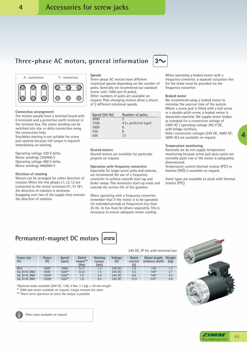
SpeedsThree-phase AC motors have differentrotational speeds depending on the number ofpoles. Generally we recommend our standardmotor with 1500 rpm (4 poles).Other numbers of poles are available onrequest. Pole-changing motors allow a choiceof 2 different rotational speeds.
Geared motorsGeared motors are available for particularprojects on request.
Operation with frequency convertersEspecially for larger screw jacks and systems,we recommend the use of a frequencyconverter to achieve smooth start-up andbrake ramps. This minimizes start-up noise andextends the service life of the gearbox.
When operating with a frequency converter,remember that if the motor is to be operatedfor extended periods at frequencies less than25 Hz, its fan must be driven separately. This isnecessary to ensure adequate motor cooling.
111© by ZIMM Austria 2013
Accessories for screw jacks
Three-phase AC motors, general information
4
4
Connection arrangementThe motors usually have a terminal board with6 terminals and a protective earth terminal inthe terminal box. The stator winding can beswitched into star or delta connection usingthe connection links.Star/delta starting is not suitable for screwjack systems because full torque is requiredimmediately on starting.
Operating voltage 230 V delta:Motor windings 230/400 VOperating voltage 400 V delta:Motor windings 400/660 V
Direction of rotatingMotors can be arranged for either direction ofrotation When the line phases L1, L2, L3 areconnected to the motor terminals U1, V1 W1,the direction of rotation is clockwiseSwapping over two of the supply lines reversesthe direction of rotation.
When operating a braked motor with afrequency converter, a separate actuation linefor the brake must be provided via thefrequency converter.
Braked motorWe recommend using a braked motor tominimise the overrun time of the system.Where a screw jack is fitted with a ball screwor a double-pitch screw, a braked motor isabsolutely essential. We supply motor brakesas standard for a connection voltage of230V AC / operating voltage 205 V DC,with bridge rectifiers. Other connection voltages (24V DC, 400V AC,500V AC) are available on request.
Temperature monitoringGenerally we do not supply temperaturemonitoring because screw jack duty cycles arenormally quite low or the motor is adequatelydimensioned.Temperature control thermal resistor (PTC) orbimetal (TKÖ) is available on request.
Some types are available ex stock with thermalresistor (PTC).
Δ - connection Y - connection
Speed (50 Hz) Number of poles3000 21500 4 (= preferred type)1000 6750 8500 12
Frame sizeIEC
Ø5356, B14C Ø8056, B14C Ø8056, B14C Ø80
Power[P]
60W85W165W250W
Speed[rpm]
30001500**1500**1500**
Ratedtorque***
[Nm]0.170.531.01.6
Startingtorque[Nm]1.41.53.04.5
Motor length(without shaft)
128149*196*241*
Voltage[V]
24V DC24V DC24V DC24V DC
Ratedcurrent
[A]2.94.58.813.5
Weight[kg]
1.22.74.35.6
24V DC, IP 54, with terminal box
Permanent-magnet DC motors
Other sizes available on request
*Optional brake available (24V DC, 13W, 2 Nm, 1.1 kg), + 44 mm length** 3000 rpm motor available on request, torque remains the same*** Short-term operation at twice the torque is possible
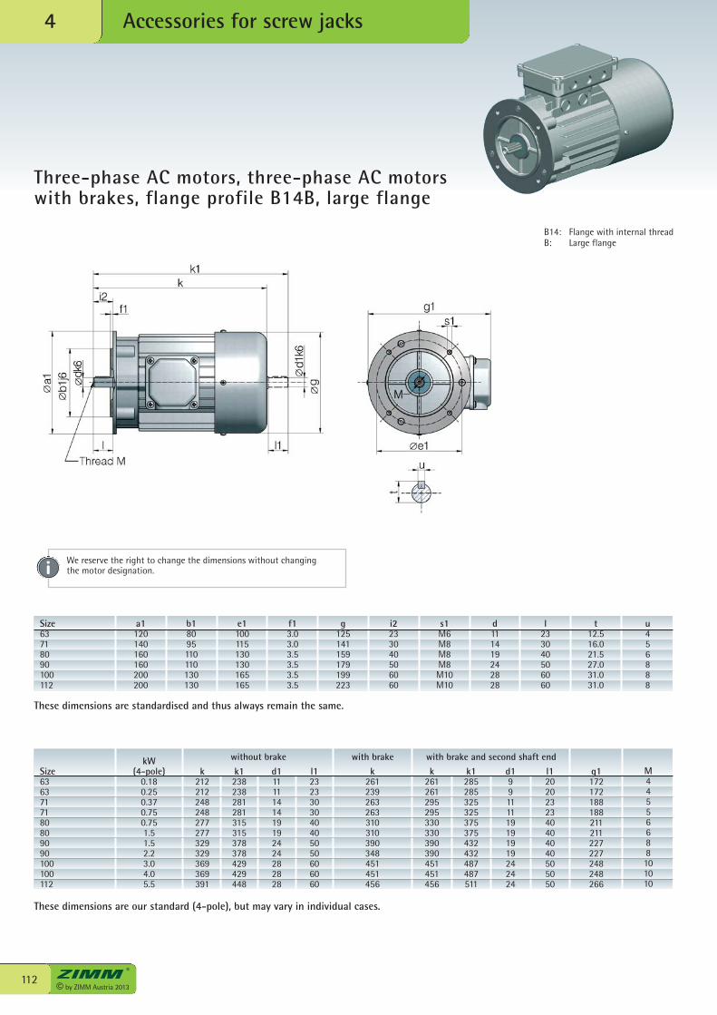
© by ZIMM Austria 2013112
Accessories for screw jacks4
Three-phase AC motors, three-phase AC motorswith brakes, flange profile B14B, large flange
Size6363717180809090100100112
kW(4-pole)
0.180.250.370.750.751.51.52.23.04.05.5
k212212248248277277329329369369391
k1238238281281315315378378429429448
d11111141419192424282828
l12323303040405050606060
k261239263263310310390348451451456
k1285285325325375375432432487487511
l12020232340404040505050
g1172172188188211211227227248248266
k261261295295330330390390451451456
d199111119191919242424
M44556688101010
without brake with brake and second shaft endwith brake
These dimensions are standardised and thus always remain the same.
These dimensions are our standard (4-pole), but may vary in individual cases.
B14: Flange with internal threadB: Large flange
Size63718090100112
a1120140160160200200
b18095110110130130
e1100115130130165165
f13.03.03.53.53.53.5
g125141159179199223
i2233040506060
d111419242828
t12.516.021.527.031.031.0
u456888
s1M6M8M8M8M10M10
l233040506060
We reserve the right to change the dimensions without changing the motor designation.
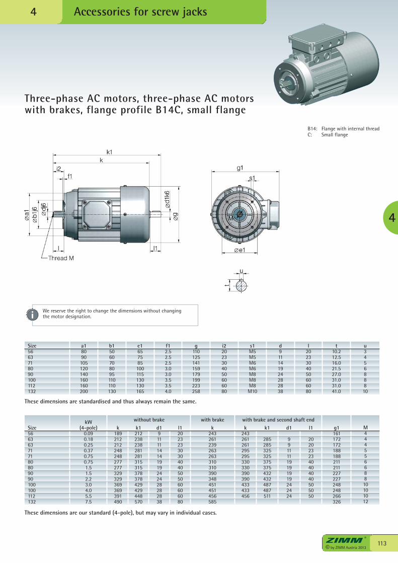
113© by ZIMM Austria 2013
Accessories for screw jacks
Three-phase AC motors, three-phase AC motorswith brakes, flange profile B14C, small flange
4
4
B14: Flange with internal threadC: Small flange
Size566363717180809090100100112132
kW(4-pole)
0.090.180.250.370.750.751.51.52.23.04.05.57.5
k189212212248248277277329329369369391490
k1212238238281281315315378378429429448570
d19111114141919242428282838
l120232330304040505060606080
k243261239263263310310390348451451456585
k1
285285325325375375432432487487511
l1
2020232340404040505050
g1161172172188188211211227227248248266326
k243261261295295330330390390433433456
d1
99111119191919242424
M44455668810101012
without brake with brake and second shaft endwith brake
Size5663718090100112132
a18090105120140160160200
b15060708095110110130
e1657585100115130130165
f12.52.52.53.03.03.53.54.0
g110125141159179199223258
i22023304050606080
d911141924282838
t10.212.516.021.527.031.031.041.0
u345688810
s1M5M5M6M6M8M8M8M10
l2023304050606080
These dimensions are standardised and thus always remain the same.
These dimensions are our standard (4-pole), but may vary in individual cases.
We reserve the right to change the dimensions without changing the motor designation.
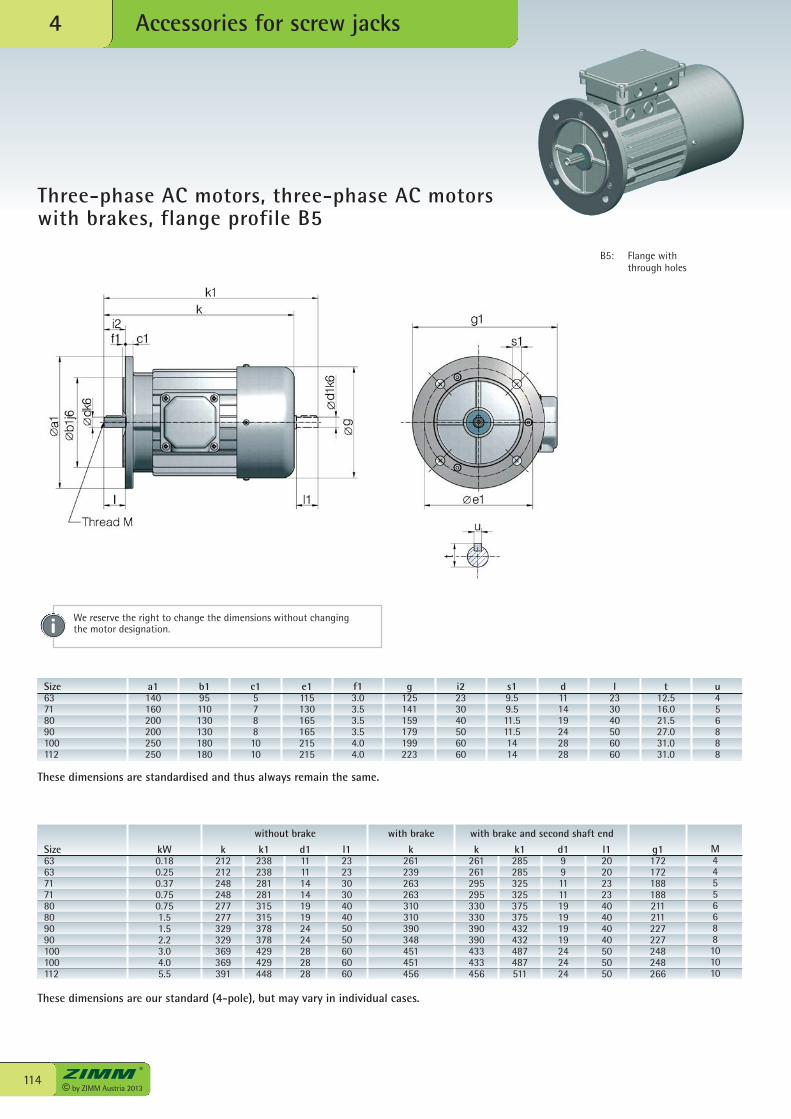
© by ZIMM Austria 2013114
Accessories for screw jacks4
Three-phase AC motors, three-phase AC motorswith brakes, flange profile B5
Size6363717180809090100100112
kW0.180.250.370.750.751.51.52.23.04.05.5
k212212248248277277329329369369391
k1238238281281315315378378429429448
d11111141419192424282828
l12323303040405050606060
k261239263263310310390348451451456
k1285285325325375375432432487487511
l12020232340404040505050
g1172172188188211211227227248248266
k261261295295330330390390433433456
d199111119191919242424
M44556688101010
without brake with brake and second shaft endwith brake
These dimensions are our standard (4-pole), but may vary in individual cases.
These dimensions are standardised and thus always remain the same.
Size63718090100112
a1140160200200250250
b195110130130180180
c157881010
e1115130165165215215
f13.03.53.53.54.04.0
g125141159179199223
s19.59.511.511.51414
l233040506060
t12.516.021.527.031.031.0
u456888
i2233040506060
d111419242828
B5: Flange with through holes
We reserve the right to change the dimensions without changing the motor designation.
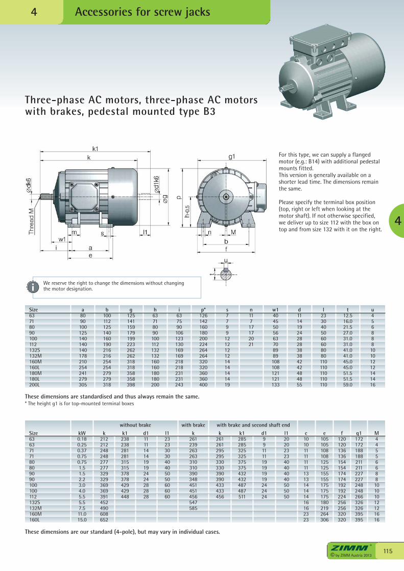
115© by ZIMM Austria 2013
Accessories for screw jacks
Three-phase AC motors, three-phase AC motorswith brakes, pedestal mounted type B3
4
4
For this type, we can supply a flangedmotor (e.g.: B14) with additional pedestalmounts fitted.This version is generally available on ashorter lead time. The dimensions remainthe same.
Please specify the terminal box position(top, right or left when looking at themotor shaft). If not otherwise specified,we deliver up to size 112 with the box ontop and from size 132 with it on the right.
Size6363717180809090100100112132S132M160M160L
kW0.180.250.370.750.751.51.52.23.04.05.55.57.511.015.0
k212212248248277277329329369369391452490608652
k1238238281281315315378378429429448
d11111141419192424282828
l12323303040405050606060
k261239263263310310390348451451456547585
k1285285325325375375432432487487511
l12020232340404040505050
k261261295295330330390390433433456
d199111119191919242424
without brake with brake and second shaft endwith brake
e105105108108125125155155175175175180219264306
g1172172188188211211227227248248266326326395395
M4455668810101012121616
c101011111111131314141416162323
f120120136136154154174174192192224256256320320
Size63718090100112132S132M160M160L180M180L200L
a8090100125140140140178210254241279305
b100112125140160190216216254254279279318
g125141159179199223262262318318358358398
h63718090100112132132160160180180200
i637590106123130169169218218231231243
p*126142160180200224264264320320360360400
n11717172021
d11141924282838384242484855
l2330405060608080110110110110110
t12.516.021.527.031.031.041.041.045.045.051.551.559.0
u45688810101212141416
s7799121212121414141419
w14045505663708989108108121121133
These dimensions are our standard (4-pole), but may vary in individual cases.
These dimensions are standardised and thus always remain the same.* The height g1 is for top-mounted terminal boxes
We reserve the right to change the dimensions without changing the motor designation.
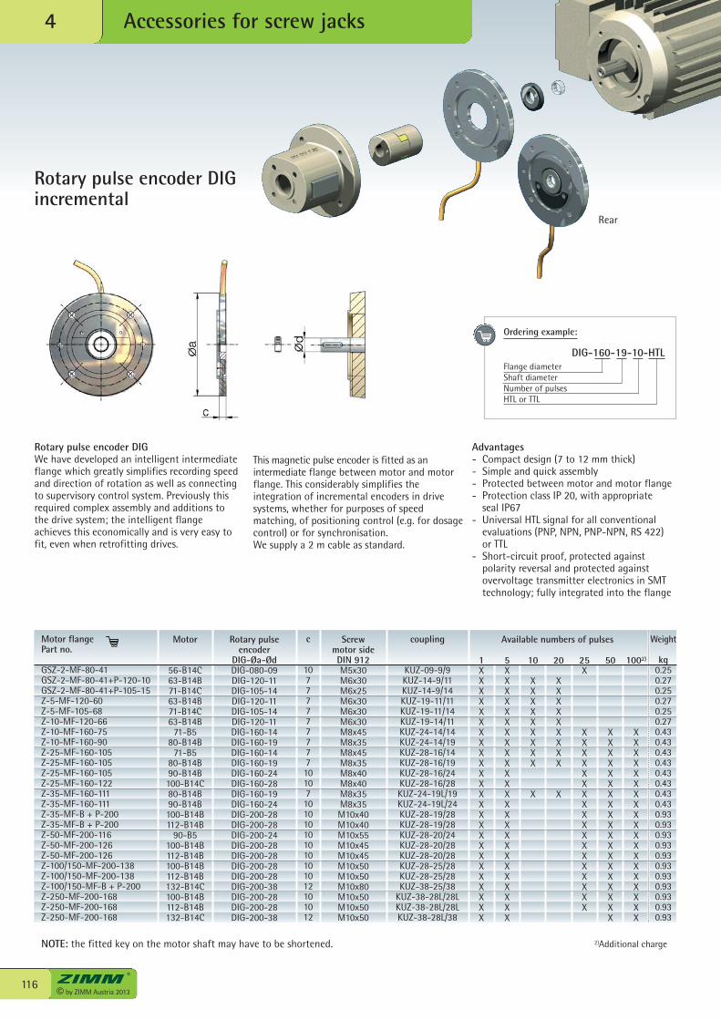
© by ZIMM Austria 2013116
Accessories for screw jacks4
Rotary pulse encoder DIGincremental
Motor
56-B14C63-B14B71-B14C63-B14B71-B14C63-B14B
71-B580-B14B
71-B580-B14B90-B14B100-B14C80-B14B90-B14B100-B14B112-B14B
90-B5100-B14B112-B14B100-B14B112-B14B132-B14C100-B14B112-B14B132-B14C
c
1077777777710107101010101010101012101012
Rotary pulseencoder
DIG-Øa-ØdDIG-080-09DIG-120-11DIG-105-14DIG-120-11DIG-105-14DIG-120-11DIG-160-14DIG-160-19DIG-160-14DIG-160-19DIG-160-24DIG-160-28DIG-160-19DIG-160-24DIG-200-28DIG-200-28DIG-200-24DIG-200-28DIG-200-28DIG-200-28DIG-200-28DIG-200-38DIG-200-28DIG-200-28DIG-200-38
Screw motor sideDIN 912M5x30M6x30M6x25M6x30M6x30M6x30M8x45M8x35M8x45M8x35M8x40M8x40M8x35M8x35M10x40M10x40M10x55M10x45M10x45M10x50M10x50M10x80M10x50M10x50M10x50
coupling
KUZ-09-9/9KUZ-14-9/11KUZ-14-9/14KUZ-19-11/11KUZ-19-11/14KUZ-19-14/11KUZ-24-14/14KUZ-24-14/19KUZ-28-16/14KUZ-28-16/19KUZ-28-16/24KUZ-28-16/28KUZ-24-19L/19KUZ-24-19L/24KUZ-28-19/28KUZ-28-19/28KUZ-28-20/24KUZ-28-20/28KUZ-28-20/28KUZ-28-25/28KUZ-28-25/28KUZ-38-25/38
KUZ-38-28L/28LKUZ-38-28L/28LKUZ-38-28L/38
1XXXXXXXXXXXXXXXXXXXXXXXXX
5XXXXXXXXXXXXXXXXXXXXXXXXX
10
XXXXXXXXX
X
20
XXXXXXXXX
X
Available numbers of pulsesMotor flange Part no.
GSZ-2-MF-80-41GSZ-2-MF-80-41+P-120-10GSZ-2-MF-80-41+P-105-15Z-5-MF-120-60Z-5-MF-105-68Z-10-MF-120-66Z-10-MF-160-75Z-10-MF-160-90Z-25-MF-160-105Z-25-MF-160-105Z-25-MF-160-105Z-25-MF-160-122Z-35-MF-160-111Z-35-MF-160-111Z-35-MF-B + P-200Z-35-MF-B + P-200Z-50-MF-200-116Z-50-MF-200-126Z-50-MF-200-126Z-100/150-MF-200-138Z-100/150-MF-200-138Z-100/150-MF-B + P-200Z-250-MF-200-168Z-250-MF-200-168Z-250-MF-200-168
Weight
kg0.250.270.250.270.250.270.430.430.430.430.430.430.430.430.930.930.930.930.930.930.930.930.930.930.93
1002)
XXXXXXXXXXXXXXXXXXX
50
XXXXXXXXXXXXXXXXXXX
25X
XXXXXXXXXXXXXXXXXX
Rear
NOTE: the fitted key on the motor shaft may have to be shortened. 2)Additional charge
Advantages- Compact design (7 to 12 mm thick)- Simple and quick assembly- Protected between motor and motor flange- Protection class IP 20, with appropriate
seal IP67- Universal HTL signal for all conventional
evaluations (PNP, NPN, PNP-NPN, RS 422)or TTL
- Short-circuit proof, protected againstpolarity reversal and protected againstovervoltage transmitter electronics in SMTtechnology; fully integrated into the flange
Rotary pulse encoder DIGWe have developed an intelligent intermediateflange which greatly simplifies recording speedand direction of rotation as well as connectingto supervisory control system. Previously thisrequired complex assembly and additions tothe drive system; the intelligent flangeachieves this economically and is very easy tofit, even when retrofitting drives.
This magnetic pulse encoder is fitted as anintermediate flange between motor and motorflange. This considerably simplifies theintegration of incremental encoders in drivesystems, whether for purposes of speedmatching, of positioning control (e.g. for dosagecontrol) or for synchronisation.We supply a 2 m cable as standard.
Ordering example:
DIG-160-19-10-HTLFlange diameterShaft diameterNumber of pulsesHTL or TTL
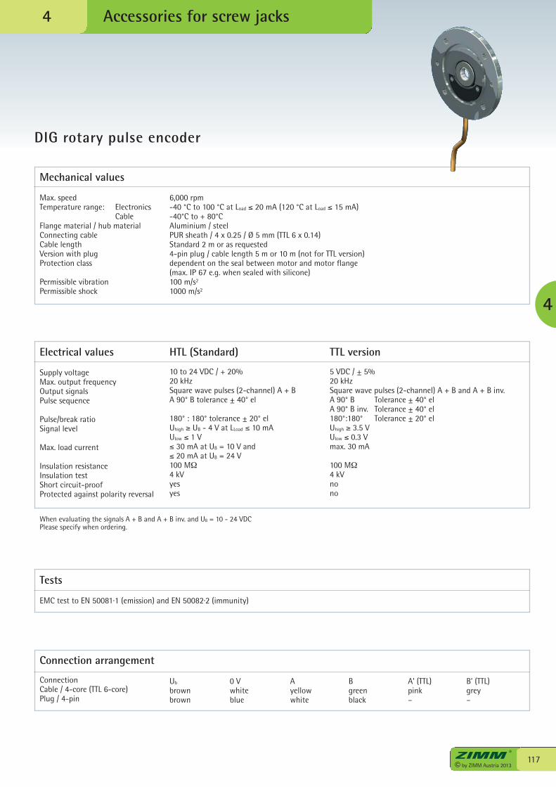
117© by ZIMM Austria 2013
Accessories for screw jacks
DIG rotary pulse encoder
4
4
Max. speedTemperature range: Electronics CableFlange material / hub materialConnecting cableCable lengthVersion with plugProtection class
Permissible vibrationPermissible shock
6,000 rpm-40 °C to 100 °C at Load ≤ 20 mA (120 °C at Load ≤ 15 mA)-40°C to + 80°CAluminium / steelPUR sheath / 4 x 0.25 / Ø 5 mm (TTL 6 x 0.14)Standard 2 m or as requested 4-pin plug / cable length 5 m or 10 m (not for TTL version)dependent on the seal between motor and motor flange(max. IP 67 e.g. when sealed with silicone)100 m/s2
1000 m/s2
Electrical values
Supply voltageMax. output frequencyOutput signalsPulse sequence
Pulse/break ratioSignal level
Max. load current
Insulation resistanceInsulation testShort circuit-proofProtected against polarity reversal
HTL (Standard)
10 to 24 VDC / + 20%20 kHzSquare wave pulses (2-channel) A + BA 90° B tolerance ± 40° el
180° : 180° tolerance ± 20° elUhigh ≥ UB - 4 V at LLoad ≤ 10 mAUlow ≤ 1 V≤ 30 mA at UB = 10 V and≤ 20 mA at UB = 24 V100 MΩ4 kVyesyes
TTL version
5 VDC / ± 5%20 kHzSquare wave pulses (2-channel) A + B and A + B inv.A 90° B Tolerance ± 40° elA 90° B inv. Tolerance ± 40° el180°:180° Tolerance ± 20° elUhigh ≥ 3.5 VUlow ≤ 0.3 Vmax. 30 mA
100 MΩ 4 kVnono
When evaluating the signals A + B and A + B inv. and UB = 10 - 24 VDCPlease specify when ordering.
Tests
EMC test to EN 50081·1 (emission) and EN 50082·2 (immunity)
Connection arrangement
ConnectionCable / 4-core (TTL 6-core)Plug / 4-pin
Ub
brownbrown
0 Vwhiteblue
Ayellowwhite
Bgreenblack
A’ (TTL)pink–
B’ (TTL)grey–
Mechanical values
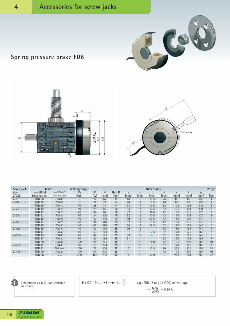
© by ZIMM Austria 2013118
Accessories for screw jacks4
Spring pressure brake FDB
For DC: P = U • I I = e.g.: FDB 17 at 205 V DC coil voltagePU
50W205V
I = = 0.24 A
new ZIMMDesignation
FDB 08FDB 08FDB 10FDB 10FDB 13FDB 13FDB 15FDB 13FDB 15FDB 15FDB 17FDB 15FDB 17FDB 20FDB 17FDB 23FDB 20FDB 26
old ZIMMDesignation
FDB 05FDB 05FDB 10FDB 10FDB 20FDB 20FDB 40FDB 20FDB 40FDB 40FDB 60FDB 40FDB 60FDB 80FDB 60FDB 150FDB 80new!
P[W]2222282834344234424250425064507664100
H[mm]
6274748282100100116116160160185185185204204230230
Hub Ø[mm]
111414161619192020252525252528283838
a[mm]
46465454626269626969816981918110191113
b[mm]
6677999999119111111111111
c[mm]
13.5 7.5 17.5 13.5 26.5 17.5 27.5 9.5 19.5 - 7.5 - - 8.0 - 13.5 - 17.0
d[mm]
2626323242425242525262526272628072-
e[mm]
8585105105130130150130150150170150170195170225195258
f[mm]
8989109109135135155135155155175155175201175231201264
g[mm]100100110110130130140130140140165140165186165196186285
Weight
[kg]1122335355757107151022
Braking torqueMB
[Nm]55101020204020404060406010060150100250
Other brakes up to Z-1000 availableon request.
DimensionsScrew jacksizeZ/GSZZ-5Z-10
Z-25
Z-35
Z-50
Z-100
Z-150
Z-250
Z-350
Brakes
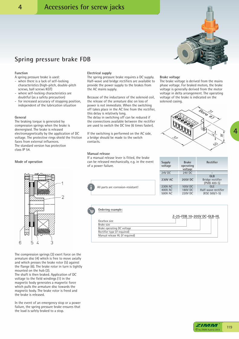
119© by ZIMM Austria 2013
Accessories for screw jacks
Spring pressure brake FDB
4
4
FunctionA spring pressure brake is used:- when there is a lack of self-locking
characteristics (high-pitch, double-pitchscrews, ball screws KGT)
- where self-locking characteristics aredoubtful (as a safety precaution)
- for increased accuracy of stopping position,independent of the lubrication situation
GeneralThe braking torque is generated bycompression springs when the brake isdeenergised. The brake is releasedelectromagnetically by the application of DCvoltage. The protective rings shield the frictionfaces from external influences. The standard version has protection class IP 54.
Mode of operation
The compression springs (3) exert force on thearmature disc (4) which is free to move axiallyand which presses the brake rotor (5) againstthe flange (6). The brake rotor in turn is tightlymounted on the hub (2).The shaft is then braked. Application of DCvoltage to the field windings (1) in themagnetic body generates a magnetic forcewhich pulls the armature disc towards themagnetic body. The brake rotor is freed andthe brake is released.
In the event of an emergency stop or a powerfailure, the spring pressure brake ensures thatthe load is safely braked to a stop.
Electrical supplyThe spring pressure brake requires a DC supply.Half-wave and bridge rectifiers are available toprovide the power supply to the brakes fromthe AC mains supply.
Because of the inductance of the solenoid coil,the release of the armature disc on loss ofpower is not immediate. When the switchingoff takes place in the AC line from the rectifier,this delay is relatively long.The delay in switching off can be reduced ifthe connections available between the rectifierare used to switch the DC line (6 times faster).
If the switching is performed on the AC side,a bridge should be made to the switchcontacts.
Manual releaseIf a manual release lever is fitted, the brakecan be released mechanically, e.g. in the eventof a power failure.
Supplyvoltage
24V DC
230V AC
230V AC400V AC500V AC
Brakeoperatingvoltage24V DC
205V DC
105V DC180V DC220V DC
Rectifier
–GLB
Bridge rectifier(PMB 400-S)
GLEHalf-wave rectifier
(KSE 500/1-S)
Brake voltageThe brake voltage is derived from the mainsphase voltage. For braked motors, the brakevoltage is generally derived from the motorvoltage in delta arrangement. The operatingvoltage of the brake is indicated on thesolenoid casing.
Ordering example:
Z-25-FDB 10-205V DC-GLB-HLGearbox sizeBrake sizeBrake operating DC voltageRectifier type (if required)Manual release HL (if required)
All parts are corrosion-resistant!
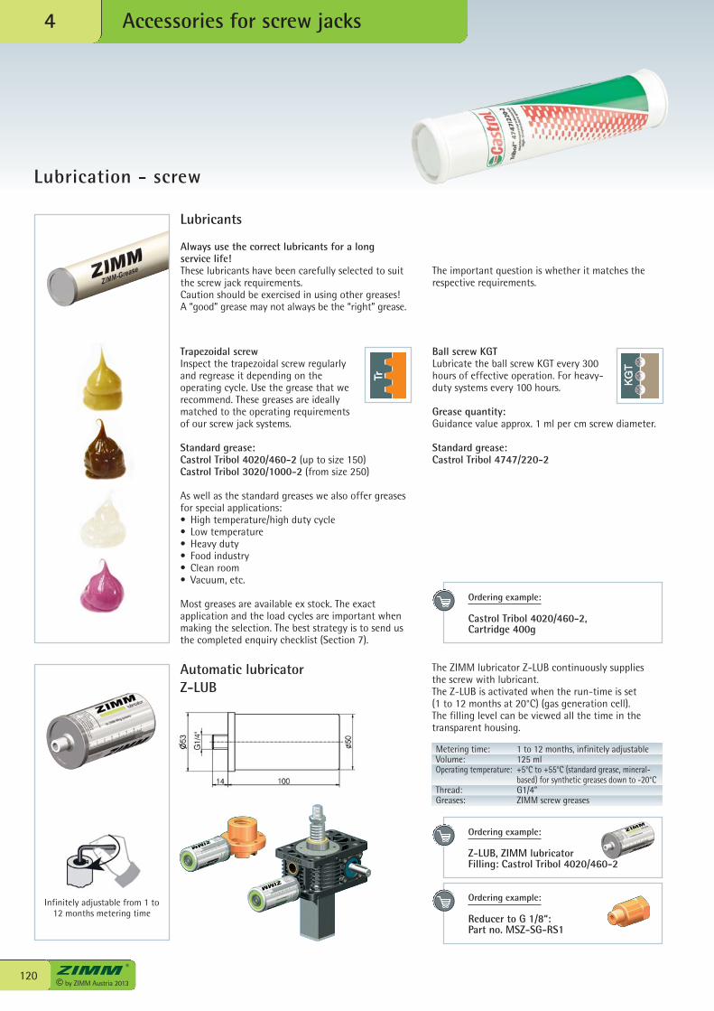
The ZIMM lubricator Z-LUB continuously suppliesthe screw with lubricant.The Z-LUB is activated when the run-time is set (1 to 12 months at 20°C) (gas generation cell). The filling level can be viewed all the time in thetransparent housing.
© by ZIMM Austria 2013120
Accessories for screw jacks4
Lubrication - screw
Automatic lubricatorZ-LUB
Lubricants
Always use the correct lubricants for a longservice life!These lubricants have been carefully selected to suitthe screw jack requirements.Caution should be exercised in using other greases!A “good” grease may not always be the “right” grease.
The important question is whether it matches therespective requirements.
Infinitely adjustable from 1 to12 months metering time
Trapezoidal screwInspect the trapezoidal screw regularlyand regrease it depending on theoperating cycle. Use the grease that werecommend. These greases are ideallymatched to the operating requirements of our screw jack systems.
Standard grease:Castrol Tribol 4020/460-2 (up to size 150)Castrol Tribol 3020/1000-2 (from size 250)
As well as the standard greases we also offer greasesfor special applications:• High temperature/high duty cycle• Low temperature• Heavy duty• Food industry• Clean room• Vacuum, etc.
Most greases are available ex stock. The exactapplication and the load cycles are important whenmaking the selection. The best strategy is to send usthe completed enquiry checklist (Section 7).
Ball screw KGTLubricate the ball screw KGT every 300hours of effective operation. For heavy-duty systems every 100 hours.
Grease quantity:Guidance value approx. 1 ml per cm screw diameter.
Standard grease:Castrol Tribol 4747/220-2
Ordering example:
Castrol Tribol 4020/460-2,Cartridge 400g
Ordering example:
Z-LUB, ZIMM lubricatorFilling: Castrol Tribol 4020/460-2
Metering time: 1 to 12 months, infinitely adjustableVolume: 125 mlOperating temperature: +5°C to +55°C (standard grease, mineral-
based) for synthetic greases down to -20°CThread: G1/4”Greases: ZIMM screw greases
Ordering example:
Reducer to G 1/8“:Part no. MSZ-SG-RS1
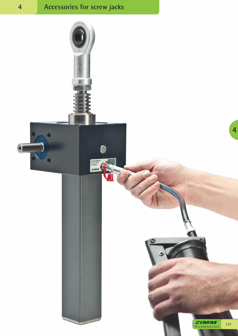
Accessories for screw jacks4
121© by ZIMM Austria 2013
4
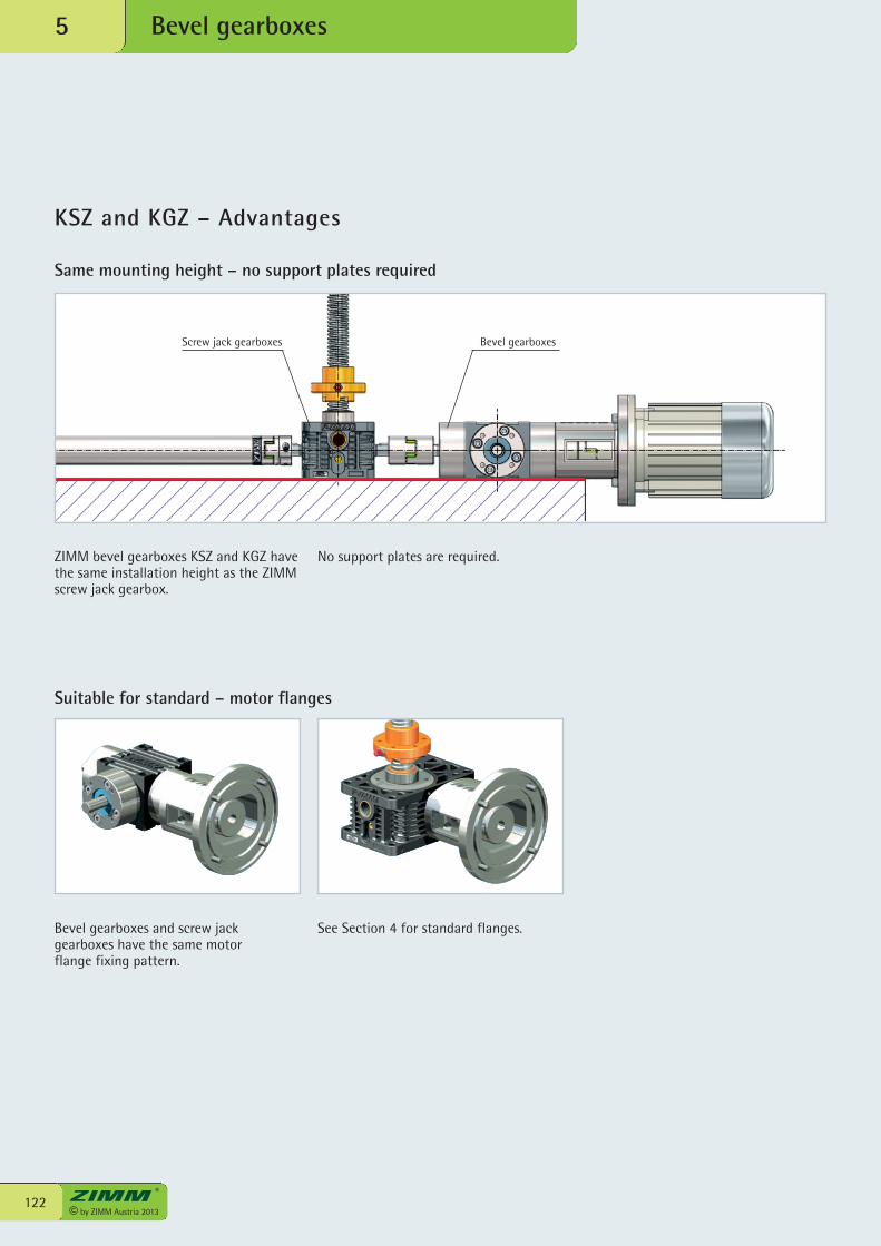
KSZ and KGZ – Advantages
Bevel gearboxes5
ZIMM bevel gearboxes KSZ and KGZ havethe same installation height as the ZIMMscrew jack gearbox.
No support plates are required.
Bevel gearboxes and screw jack gearboxes have the same motor flange fixing pattern.
See Section 4 for standard flanges.
Screw jack gearboxes Bevel gearboxes
Same mounting height – no support plates required
Suitable for standard – motor flanges
122© by ZIMM Austria 2013
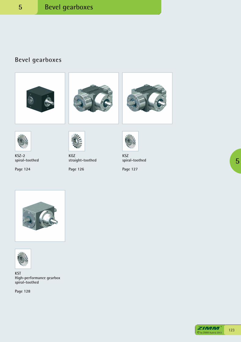
Bevel gearboxes
Bevel gearboxes
123© by ZIMM Austria 2013
5
5
KSZ-2spiral-toothed
Page 124
KGZstraight-toothed
Page 126
KSZspiral-toothed
Page 127
KSTHigh-performance gearboxspiral-toothed
Page 128
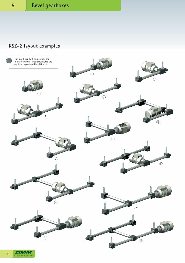
© by ZIMM Austria 2013124
Bevel gearboxes5
3
5
4
6
7
8
9
10
11
12
13
1
2
The KSZ-2 is a bolt-on gearbox andtherefore where larger screw jacks areused the layouts will be different.
KSZ-2 layout examples
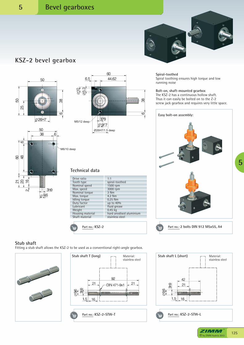
125© by ZIMM Austria 2013
Bevel gearboxes
KSZ-2 bevel gearbox
5
5
Stub shaft T (long)
Easy bolt-on assembly:
Material: stainless steel
Spiral-toothedSpiral toothing ensures high torque and low running noise
Bolt-on, shaft-mounted gearboxThe KSZ-2 has a continuous hollow shaft. Thus it can easily be bolted on to the Z-2 screw jack gearbox and requires very little space.
Stub shaftFitting a stub shaft allows the KSZ-2 to be used as a conventional right-angle gearbox.
Technical data
Drive ratio 1:1Tooth type spiral-toothedNominal speed 1500 rpmMax. speed 3000 rpmNominal torque 3 NmMax. torque 4.2 NmIdling torque 0.25 NmDuty factor up to 40%Lubricant fluid greaseWeight 0.45 kgHousing material hard anodised aluminiumShaft material stainless steel
Stub shaft L (short) Material: stainless steel
Part no.: KSZ-2 Part no.: 2 bolts DIN 912 M5x55, A4
Part no.: KSZ-2-STW-T Part no.: KSZ-2-STW-L
Ø26H7/1.5 deep
M5/12 deep
M6/10 deep
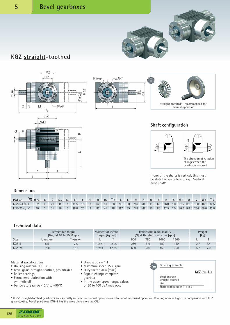
© by ZIMM Austria 2013126
Bevel gearboxes5
KGZ straight-toothed
L version6.514.0
T version7.516.0
L T0.429 0.5651.283 1.569
500250600
750210500
1000180450
1500150360
L T2.7 3.45.7 7.0
Permissible torque Moment of inertia Permissible radial load FR Weight [Nm] at 10 to 1500 rpm Torque [kg cm2] [N] at the shaft end at n1 [rpm] [kg]SizeKGZ-5KGZ-25
Material specifications• Housing material: GGL 20• Bevel gears: straight-toothed, gas nitrided• Roller bearings• Permanent lubrication with synthetic oil • Temperature range -10°C to +90°C
• Drive ratio i = 1:1• Maximum speed 1500 rpm• Duty factor 20% (max.)• Repair: change complete gearbox• In the upper speed range, values of 90 to 100 dBA may occur
Shaft configuration
If one of the shafts is vertical, this must be stated when ordering: e.g.: “vertical drive shaft”
* KGZ-1 straight-toothed gearboxes are especially suitable for manual operation or infrequent motorised operation. Running noise is higher in comparison with KSZspiral-toothed bevel gearboxes. KGZ-1 has the same dimensions as KSZ.
Dimensions
Part no.KGZ-5-L/T-1KGZ-25-L/T-1
Ø AH7
3240
B23
C2131
Dj6
1116
Eh9
45
E1
11.518.0
F1625
G33
H6282
H1
3141
K6078
L90117
MM6M8
NM6M8
O1315
P6986
R36.047.5
S1.01.5
Ø T61.580.0
U126.0164.5
V180234
Ø Z46.160.0
Z32.542.0
L1
3039
Technical data
straight-toothed* - recommended for manual operation
L T
The direction of rotationchanges when thegearbox is reversed
Ordering example:
KGZ-25-T-1Bevel gearbox straight-toothedSizeShaft configuration T-1 or L-1
B deep
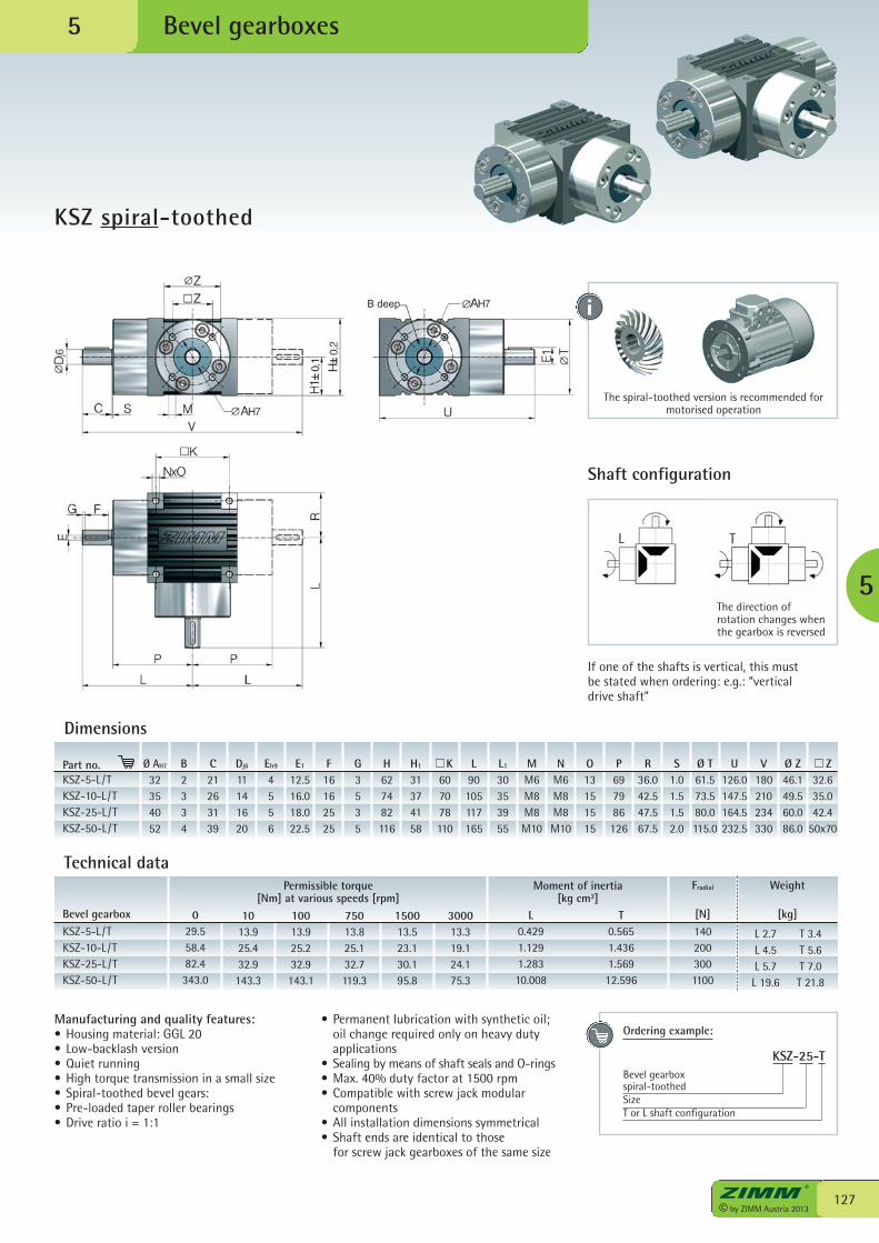
127© by ZIMM Austria 2013
Bevel gearboxes
KSZ spiral-toothed
5
5
Shaft configuration
If one of the shafts is vertical, this must be stated when ordering: e.g.: “vertical drive shaft”
The spiral-toothed version is recommended formotorised operation
L T
The direction ofrotation changes whenthe gearbox is reversed
029.558.482.4343.0
1013.925.432.9143.3
10013.925.232.9143.1
75013.825.132.7119.3
150013.523.130.195.8
300013.319.124.175.3
Fradial
[N]1402003001100
Weight
[kg]
L 2.7 T 3.4 L 4.5 T 5.6 L 5.7 T 7.0 L 19.6 T 21.8
Bevel gearboxKSZ-5-L/TKSZ-10-L/TKSZ-25-L/TKSZ-50-L/T
Moment of inertia [kg cm2]
L T 0.429 0.565 1.129 1.436 1.283 1.569 10.008 12.596
Manufacturing and quality features:• Housing material: GGL 20• Low-backlash version• Quiet running• High torque transmission in a small size • Spiral-toothed bevel gears:• Pre-loaded taper roller bearings• Drive ratio i = 1:1
• Permanent lubrication with synthetic oil; oil change required only on heavy duty applications• Sealing by means of shaft seals and O-rings• Max. 40% duty factor at 1500 rpm• Compatible with screw jack modular components• All installation dimensions symmetrical• Shaft ends are identical to those for screw jack gearboxes of the same size
Dimensions
Part no.KSZ-5-L/TKSZ-10-L/TKSZ-25-L/TKSZ-50-L/T
Ø AH7
32354052
B2334
C21263139
Dj6
11141620
Eh9
4556
E1
12.516.018.022.5
F16162525
G3535
H627482116
H1
31374158
K607078110
L90105117165
MM6M8M8M10
NM6M8M8M10
O13151515
P697986126
R36.042.547.567.5
S1.01.51.52.0
Ø T61.573.580.0115.0
U126.0147.5164.5232.5
V180210234330
Ø Z46.149.560.086.0
Z32.635.042.4
50x70
L1
30353955
Technical data
Ordering example:
KSZ-25-TBevel gearbox spiral-toothedSizeT or L shaft configuration
Permissible torque [Nm] at various speeds [rpm]
B deep
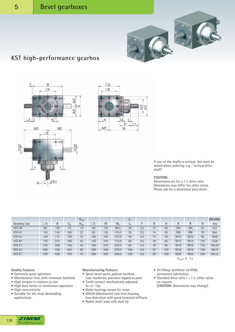
© by ZIMM Austria 2013128
Bevel gearboxes5
KST high-performance gearbox
Quality features• Extremely quiet operation• Maintenance-free, with minimum backlash• High torques in relation to size• High duty factor or continuous operation• High concentricity• Suitable for the most demanding applications
• Oil filling: synthetic oil HT68, permanent lubrication• Standard drive ratio i = 1:1, other ratios on request (CAUTION: Dimensions may change)
Kdeep= K · 1.5
If one of the shafts is vertical, this must bestated when ordering: e.g.: “vertical driveshaft”
CAUTION:Dimensions are for a 1:1 drive ratio.Dimensions may differ for other ratios. Please ask for a dimension data sheet.
Gearbox sizeKST-00KST-01KST-A1KST-B1KST-C1KST-D1KST-E1
A80110140170210260330
B110145175215260330430
Cj7
74102130160195245310
D1j6
D2j6
14223242556575
E6082105130160200260
M110135165210275340435
M2
88.5111.0137.0172.0220.0270.0340.0
L1
L2
3035456085100120
F3.53.54.54.55.05.05.0
G13141418182329
H4045506585110150
KM6M8M10M12M16M16M20
RM6M8M10M12M16M16M20
O527090110135150230
DIN 6885key5x56x610x812x816x1018x1120x12
Manufacturing features• Spiral bevel gears, palloid-toothed, case-hardened, precision lapped as pairs• Tooth contact mechanically adjusted to +/- 15µ• Roller bearings tested for noise• GD250 (Meehanite) cast-iron housing, low-distortion with good torsional stiffness• Radial shaft seals with dust lip
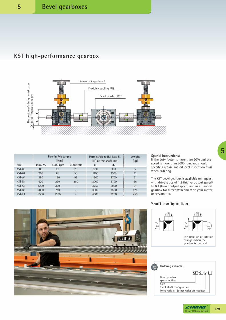
Shaft configuration
L T
The direction of rotationchanges when thegearbox is reversed
129© by ZIMM Austria 2013
Bevel gearboxes
KST high-performance gearbox
5
5
Permissible torque [Nm]
Permissible radial load FR
[N] at the shaft endWeight
[kg]d1
300110015002000325038004500
d2
300110027003700500075009200
3000 rpm205095160
---
1500 rpm28651302303907401300
max. Md
80200380620120020003500
SizeKST-00KST-01KST-A1KST-B1KST-C1KST-D1KST-E1
511213664124250
The
cust
omer
’s de
sign
mus
t ca
ter
for
diff
eren
ces
in h
eigh
t
Screw jack gearbox Z
Flexible coupling KUZ
Bevel gearbox KST
Special instructions:If the duty factor is more than 20% and thespeed is more than 3000 rpm, you shouldspecify a grease and oil level inspection glasswhen ordering.
The KST bevel gearbox is available on requestwith drive ratios of 1:2 (higher output speed)to 6:1 (lower output speed) and as a flangedgearbox for direct attachment to your motoror servomotor.
Ordering example:
KST-01-L-1:1Bevel gearbox spiral-toothedSizeT or L shaft configurationDrive ratio 1:1 (other ratios on request)
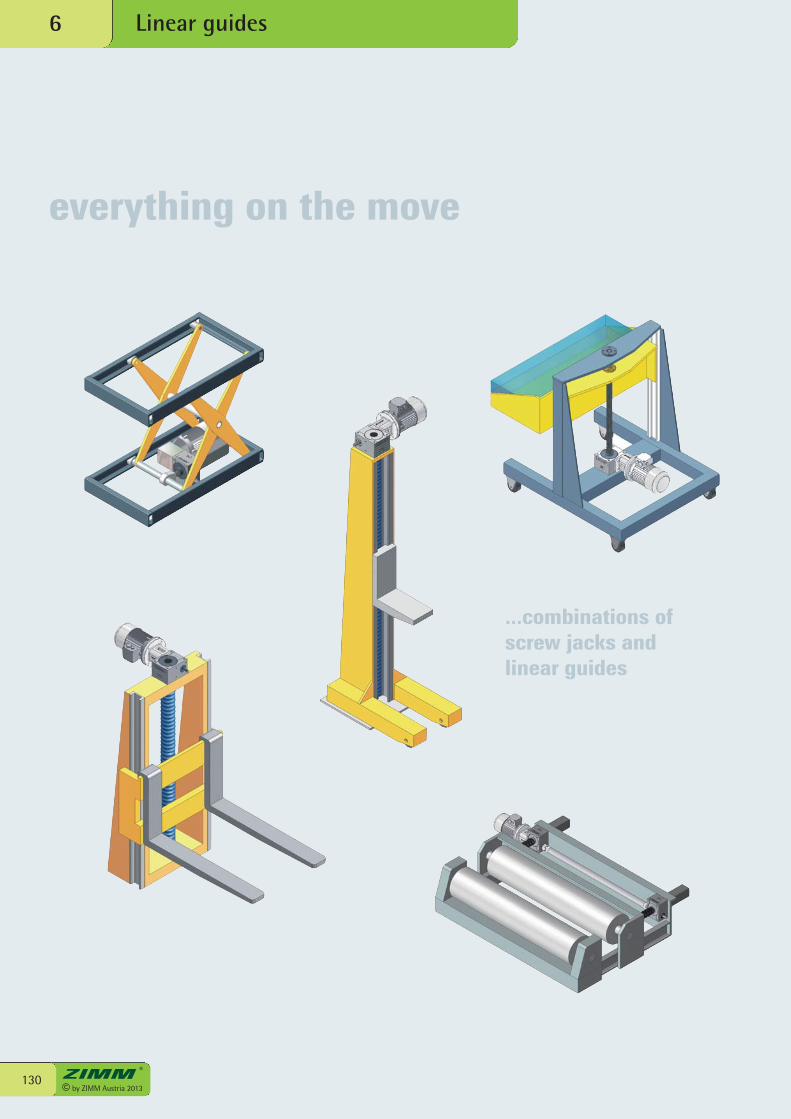
everything on the move
Linear guides6
© by ZIMM Austria 2013130
...combinations ofscrew jacks andlinear guides
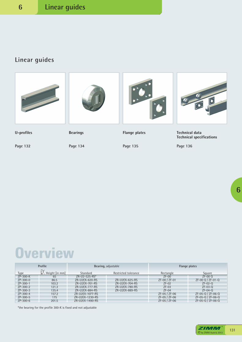
Linear guides
U-profiles
Page 132
Bearings
Page 134
Flange plates
Page 135
Technical dataTechnical specifications
Page 136
3© ZIMM Austria 2012
Linear guides
131© by ZIMM Austria 2013
6
6
OverviewProfile Bearing, adjustable Flange plates
Type Height [in mm] Standard Restricted tolerance Rectangle SquareZP-300-K 65 ZR-U2-525-RS* ZF-00 ZF-00 QZP-300-0 86.5 ZR-U2EX-620-RS ZR-U2EX-625-RS ZF-00 / ZF-01 ZF-00 Q / ZF-01-QZP-300-1 103.2 ZR-U2EX-701-RS ZR-U2EX-704-RS ZF-02 ZF-02-QZP-300-2 121.3 ZR-U2EX-777-RS ZR-U2EX-780-RS ZF-03 ZF-03-QZP-300-3 135.4 ZR-U2EX-884-RS ZR-U2EX-889-RS ZF-04 ZF-04-QZP-300-4 157.2 ZR-U2EX-1077-RS ZF-05 / ZF-06 ZF-05-Q / ZF-06-QZP-300-5 175 ZR-U2EX-1230-RS ZF-05 / ZF-06 ZF-05-Q / ZF-06-QZP-300-6 201.5 ZR-U2EX-1490-RS ZF-05 / ZF-06 ZF-05-Q / ZF-06-Q
*the bearing for the profile 300-K is fixed and not adjustable
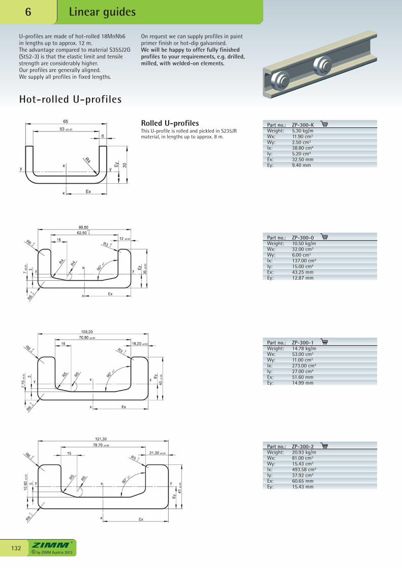
Part no.: ZP-300-KWeight: 5.30 kg/mWx: 11.90 cm3
Wy: 2.50 cm3
Ix: 38.80 cm4
Iy: 5.20 cm4
Ex: 32.50 mmEy: 9.40 mm
© by ZIMM Austria 2013132
Linear guides6
Hot-rolled U-profiles
Rolled U-profilesThis U-profile is rolled and pickled in S235JRmaterial, in lengths up to approx. 8 m.
U-profiles are made of hot-rolled 18MnNb6in lengths up to approx. 12 m.The advantage compared to material S355J2G(St52-3) is that the elastic limit and tensilestrength are considerably higher. Our profiles are generally aligned.We supply all profiles in fixed lengths.
On request we can supply profiles in paintprimer finish or hot-dip galvanised. We will be happy to offer fully finishedprofiles to your requirements, e.g. drilled,milled, with welded-on elements.
Part no.: ZP-300-0Weight: 10.50 kg/mWx: 32.00 cm3
Wy: 6.00 cm3
Ix: 137.00 cm4
Iy: 15.00 cm4
Ex: 43.25 mmEy: 12.87 mm
Part no.: ZP-300-1Weight: 14.78 kg/mWx: 53.00 cm3
Wy: 11.00 cm3
Ix: 273.00 cm4
Iy: 27.00 cm4
Ex: 51.60 mmEy: 14.99 mm
Part no.: ZP-300-2Weight: 20.93 kg/mWx: 81.00 cm3
Wy: 15.43 cm3
Ix: 493.58 cm4
Iy: 37.92 cm4
Ex: 60.65 mmEy: 15.43 mm
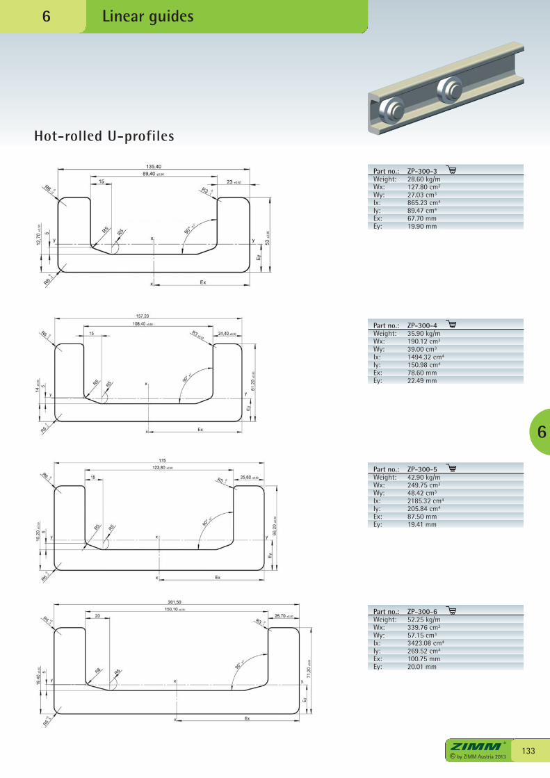
133© by ZIMM Austria 2013
Linear guides
Hot-rolled U-profiles
6
6
Part no.: ZP-300-3Weight: 28.60 kg/mWx: 127.80 cm3
Wy: 27.03 cm3
Ix: 865.23 cm4
Iy: 89.47 cm4
Ex: 67.70 mmEy: 19.90 mm
Part no.: ZP-300-4Weight: 35.90 kg/mWx: 190.12 cm3
Wy: 39.00 cm3
Ix: 1494.32 cm4
Iy: 150.98 cm4
Ex: 78.60 mmEy: 22.49 mm
Part no.: ZP-300-5Weight: 42.90 kg/mWx: 249.75 cm3
Wy: 48.42 cm3
Ix: 2185.32 cm4
Iy: 205.84 cm4
Ex: 87.50 mmEy: 19.41 mm
Part no.: ZP-300-6Weight: 52.25 kg/mWx: 339.76 cm3
Wy: 57.15 cm3
Ix: 3423.08 cm4
Iy: 269.52 cm4
Ex: 100.75 mmEy: 20.01 mm
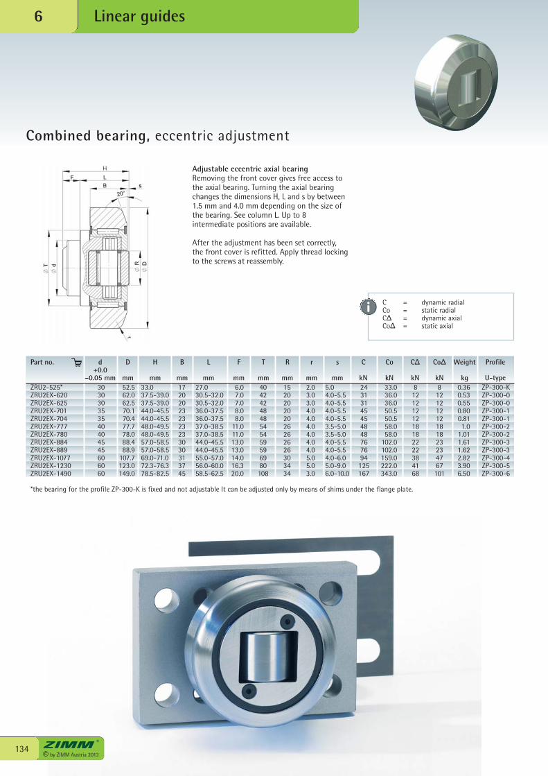
© by ZIMM Austria 2013134
Linear guides6
Combined bearing, eccentric adjustment
Adjustable eccentric axial bearingRemoving the front cover gives free access tothe axial bearing. Turning the axial bearingchanges the dimensions H, L and s by between1.5 mm and 4.0 mm depending on the size ofthe bearing. See column L. Up to 8intermediate positions are available.
After the adjustment has been set correctly,the front cover is refitted. Apply thread lockingto the screws at reassembly.
ZRU2-525* 30 52.5 33.0 17 27.0 6.0 40 15 2.0 5.0 24 33.0 8 8 0.36 ZP-300-KZRU2EX-620 30 62.0 37.5-39.0 20 30.5-32.0 7.0 42 20 3.0 4.0-5.5 31 36.0 12 12 0.53 ZP-300-0ZRU2EX-625 30 62.5 37.5-39.0 20 30.5-32.0 7.0 42 20 3.0 4.0-5.5 31 36.0 12 12 0.55 ZP-300-0ZRU2EX-701 35 70.1 44.0-45.5 23 36.0-37.5 8.0 48 20 4.0 4.0-5.5 45 50.5 12 12 0.80 ZP-300-1ZRU2EX-704 35 70.4 44.0-45.5 23 36.0-37.5 8.0 48 20 4.0 4.0-5.5 45 50.5 12 12 0.81 ZP-300-1ZRU2EX-777 40 77.7 48.0-49.5 23 37.0-38.5 11.0 54 26 4.0 3.5-5.0 48 58.0 18 18 1.0 ZP-300-2ZRU2EX-780 40 78.0 48.0-49.5 23 37.0-38.5 11.0 54 26 4.0 3.5-5.0 48 58.0 18 18 1.01 ZP-300-2ZRU2EX-884 45 88.4 57.0-58.5 30 44.0-45.5 13.0 59 26 4.0 4.0-5.5 76 102.0 22 23 1.61 ZP-300-3ZRU2EX-889 45 88.9 57.0-58.5 30 44.0-45.5 13.0 59 26 4.0 4.0-5.5 76 102.0 22 23 1.62 ZP-300-3ZRU2EX-1077 60 107.7 69.0-71.0 31 55.0-57.0 14.0 69 30 5.0 4.0-6.0 94 159.0 38 47 2.82 ZP-300-4ZRU2EX-1230 60 123.0 72.3-76.3 37 56.0-60.0 16.3 80 34 5.0 5.0-9.0 125 222.0 41 67 3.90 ZP-300-5ZRU2EX-1490 60 149.0 78.5-82.5 45 58.5-62.5 20.0 108 34 3.0 6.0-10.0 167 343.0 68 101 6.50 ZP-300-6
*the bearing for the profile ZP-300-K is fixed and not adjustable It can be adjusted only by means of shims under the flange plate.
Part no. d D H B L F T R r s C Co CΔ CoΔ Weight Profile +0.0 –0.05 mm mm mm mm mm mm mm mm mm mm kN kN kN kN kg U-type
C = dynamic radial Co = static radialCΔ = dynamic axialCoΔ = static axial
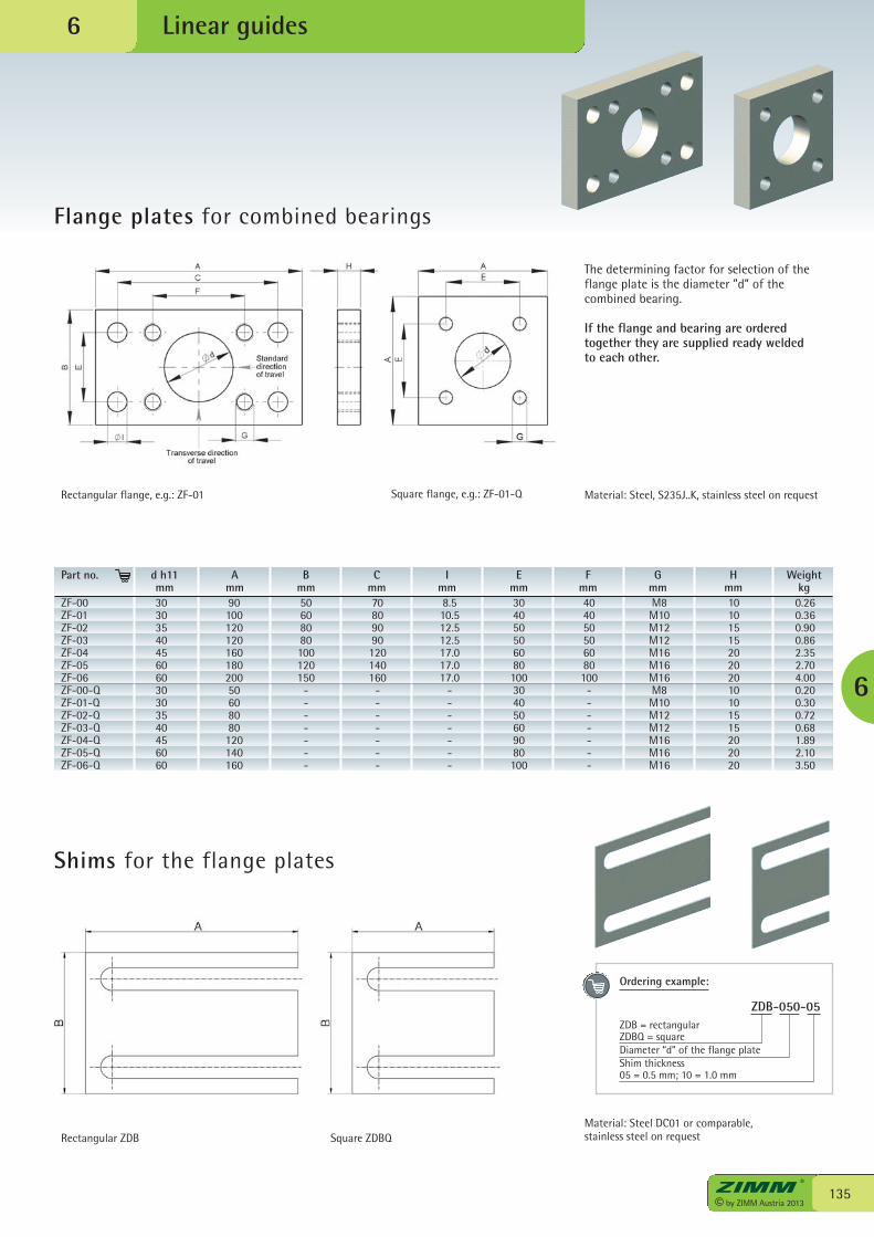
135© by ZIMM Austria 2013
Linear guides
Flange plates for combined bearings
6
6
The determining factor for selection of theflange plate is the diameter ”d” of thecombined bearing.
If the flange and bearing are orderedtogether they are supplied ready welded to each other.
ZF-00 30 90 50 70 8.5 30 40 M8 10 0.26ZF-01 30 100 60 80 10.5 40 40 M10 10 0.36ZF-02 35 120 80 90 12.5 50 50 M12 15 0.90ZF-03 40 120 80 90 12.5 50 50 M12 15 0.86ZF-04 45 160 100 120 17.0 60 60 M16 20 2.35ZF-05 60 180 120 140 17.0 80 80 M16 20 2.70ZF-06 60 200 150 160 17.0 100 100 M16 20 4.00ZF-00-Q 30 50 - - - 30 - M8 10 0.20ZF-01-Q 30 60 - - - 40 - M10 10 0.30ZF-02-Q 35 80 - - - 50 - M12 15 0.72ZF-03-Q 40 80 - - - 60 - M12 15 0.68ZF-04-Q 45 120 - - - 90 - M16 20 1.89ZF-05-Q 60 140 - - - 80 - M16 20 2.10ZF-06-Q 60 160 - - - 100 - M16 20 3.50
Part no. d h11 A B C I E F G H Weight mm mm mm mm mm mm mm mm mm kg
Rectangular flange, e.g.: ZF-01 Square flange, e.g.: ZF-01-Q
Shims for the flange plates
Rectangular ZDB Square ZDBQMaterial: Steel DC01 or comparable,stainless steel on request
Material: Steel, S235J..K, stainless steel on request
Ordering example:
ZDB-050-05ZDB = rectangularZDBQ = squareDiameter “d” of the flange plateShim thickness05 = 0.5 mm; 10 = 1.0 mm
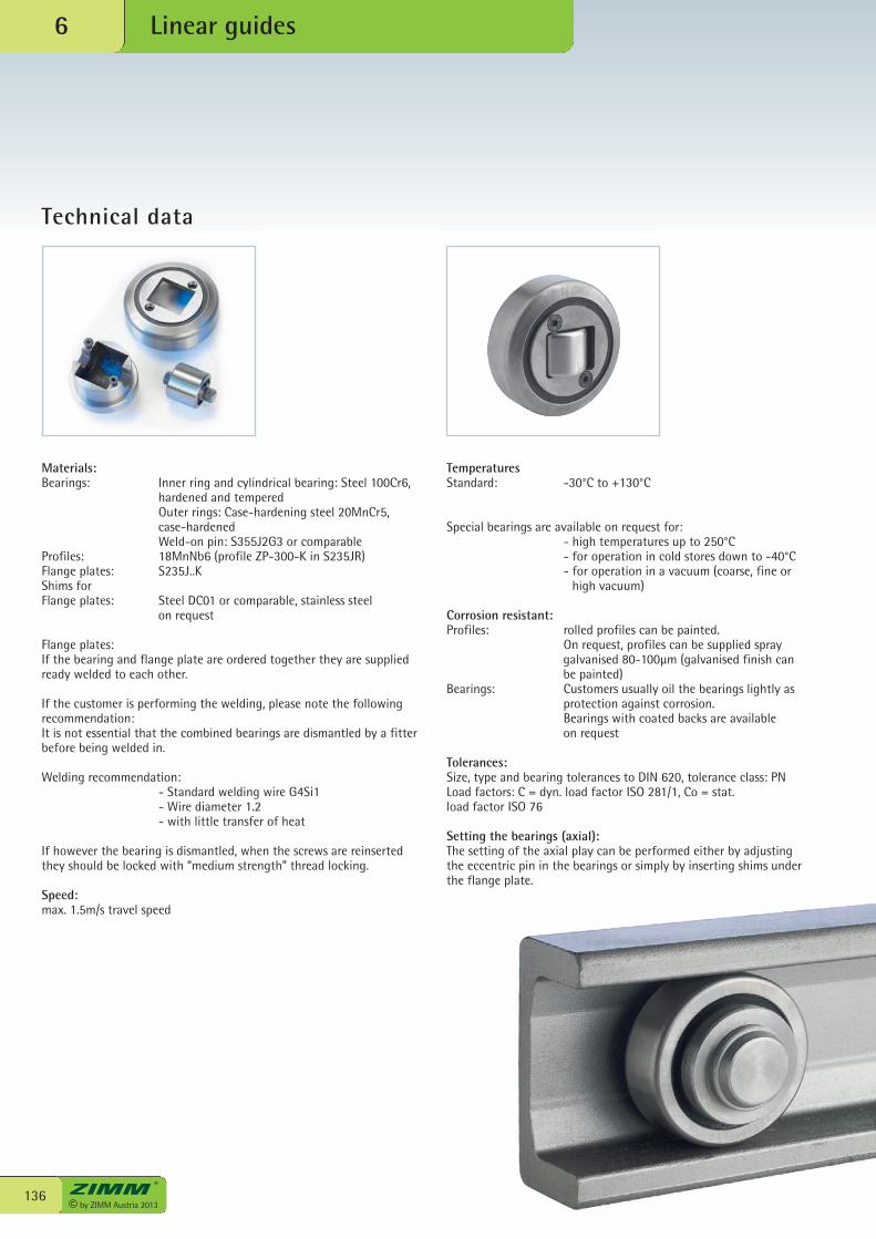
© by ZIMM Austria 2013136
Linear guides6
Technical data
Materials:Bearings: Inner ring and cylindrical bearing: Steel 100Cr6,
hardened and tempered Outer rings: Case-hardening steel 20MnCr5,
case-hardened Weld-on pin: S355J2G3 or comparableProfiles: 18MnNb6 (profile ZP-300-K in S235JR)Flange plates: S235J..KShims for Flange plates: Steel DC01 or comparable, stainless steel
on request
Flange plates:If the bearing and flange plate are ordered together they are suppliedready welded to each other.
If the customer is performing the welding, please note the followingrecommendation:It is not essential that the combined bearings are dismantled by a fitterbefore being welded in.
Welding recommendation: - Standard welding wire G4Si1 - Wire diameter 1.2 - with little transfer of heat
If however the bearing is dismantled, when the screws are reinsertedthey should be locked with “medium strength” thread locking.
Speed: max. 1.5m/s travel speed
TemperaturesStandard: -30°C to +130°C
Special bearings are available on request for: - high temperatures up to 250°C - for operation in cold stores down to -40°C - for operation in a vacuum (coarse, fine or
high vacuum)
Corrosion resistant:Profiles: rolled profiles can be painted. On request, profiles can be supplied spray
galvanised 80-100µm (galvanised finish canbe painted)
Bearings: Customers usually oil the bearings lightly asprotection against corrosion.
Bearings with coated backs are availableon request
Tolerances:Size, type and bearing tolerances to DIN 620, tolerance class: PNLoad factors: C = dyn. load factor ISO 281/1, Co = stat.load factor ISO 76
Setting the bearings (axial):The setting of the axial play can be performed either by adjustingthe eccentric pin in the bearings or simply by inserting shims underthe flange plate.
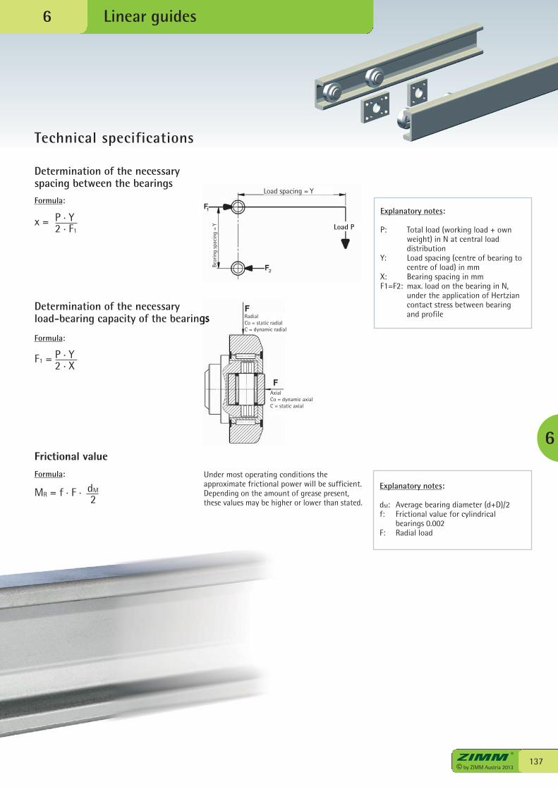
137© by ZIMM Austria 2013
Linear guides
Technical specifications
6
6
MR = f . F . dM
2
F1 = P . Y2 . X
Determination of the necessaryspacing between the bearings
Explanatory notes:
P: Total load (working load + ownweight) in N at central loaddistribution
Y: Load spacing (centre of bearing tocentre of load) in mm
X: Bearing spacing in mmF1=F2: max. load on the bearing in N,
under the application of Hertziancontact stress between bearingand profile
Determination of the necessary load-bearing capacity of the bearings
Frictional value
x = P . Y2 . F1
Formula:
Formula:
Explanatory notes:
dM: Average bearing diameter (d+D)/2f: Frictional value for cylindrical
bearings 0.002F: Radial load
Formula: Under most operating conditions theapproximate frictional power will be sufficient. Depending on the amount of grease present,these values may be higher or lower than stated.
Load spacing = Y
RadialCo = static radialC = dynamic radial
Bear
ing
spac
ing
= Y
AxialCo = dynamic axialC = static axial
Load P

environment and people...© by ZIMM Austria 2013
138
Laternsertal “Walser Kamm”
in harmony!139
© by ZIMM Austria 2013
6

© by ZIMM Austria 2013140
Checklists7
Checklists - Sheet 1 - Parameters
Company: Date:
Address: Phone:
Contact: Fax:
Dept.: E-mail
1. max. lifting force in kN
- per gearbox ________ kN for the entire system________ kN
- in tension ________ kN in compression ________ kN
- Load: static ________ kN dynamic ________ kN
2. max. lift/ travel ________ mm c effective working stroke ___________ mm
For short stroke applications (eff. working stroke < gearbox height): c regular lubrication stroke practical c not practical
3. Lifting speed
c type N = 25 mm/s (1.5 m/min) c type L = 6.25 mm/s (0.375 m/min) c ___________________ mm/s
4. Duty factor, work cycle, description of cycle
_________ strokes per hour _________ strokes per day Hours per day c 8 c 16 c 24
For high duty factors or long strokes, please provide an exact detailed description on page 141, 4a
5. Type c S “Translating screw” c R “Rotating screw” | c Z screw jack c GSZ screw jack
6. Motor c Three-phase AC motor c With brake c Manual release c ___________________
7. Operating conditions: c Dry c Humid c Dust c Chipping c ___________________
c Guided movement c No guides (no dyn. lateral forces)
Ambient temperature: min. _________ °C max. _________ °C
If possible please provide an exact description or sketch on page 141, 7a
8. Standard layouts no.: _____________ Size: MA1 ________ MA2 _______ MA3 ________ MA4 _______ MA5 ________
see standard layouts, checklist sheets 5 and 6 (for multi-jack systems)
9. Quantity Required: _________________________________ Series: _____________________________________
10. Schedule Quotation: _________________________________ Delivery: _____________________________________
Installation axis
c vertical c horizontal c pivoting
Type of load
c smooth c impact loads c vibration
quick and easy
copy
select
fax / e-mail
or PDF at www.zimm.at
(Contacts: Section 10)
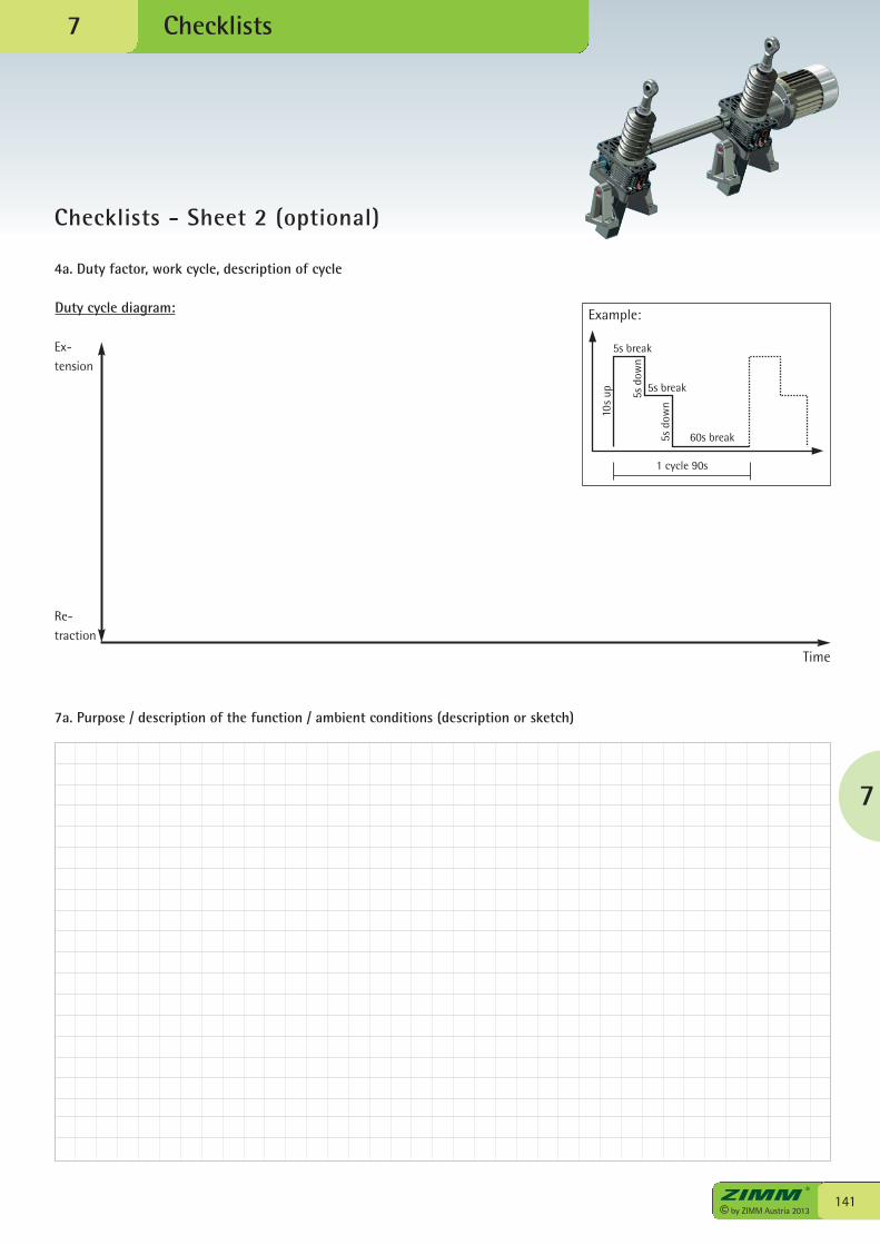
7
141© by ZIMM Austria 2013
Checklists
Checklists - Sheet 2 (optional)
7
Duty cycle diagram:
Ex-tension
Re-traction
Example:
1 cycle 90s
5s break
5s break
60s break
10s
up
5s d
own
5s d
own
4a. Duty factor, work cycle, description of cycle
7a. Purpose / description of the function / ambient conditions (description or sketch)
Time
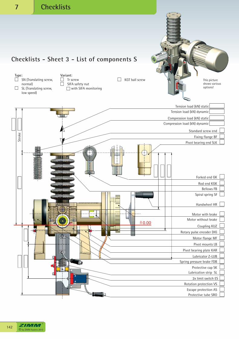
© by ZIMM Austria 2013142
Checklists7
Checklists - Sheet 3 - List of components S
Tension load (kN) static
Tension load (kN) dynamic
Compression load (kN) static
Compression load (kN) dynamic
Standard screw end
Fixing flange BF
Pivot bearing end SLK
Forked end GK
Rod end KGK
Bellows FB
Spiral spring SF
Handwheel HR
Motor with brakeMotor without brake
Coupling KUZ
Rotary pulse encoder DIG
Motor flange MF
Pivot mounts LB
Pivot bearing plate KAR
Lubricator Z-LUBSpring pressure brake FDB
Protective cap SKLubrication strip SL
2x limit switch ES
Rotation protection VS
Escape protection ASProtective tube SRO
Stro
ke
Type: SN (Translating screw,
normal) SL (Translating screw,
low speed)
Variant: Tr screw SIFA safety nut with SIFA monitoring
This pictureshows variousoptions!
KGT ball screw
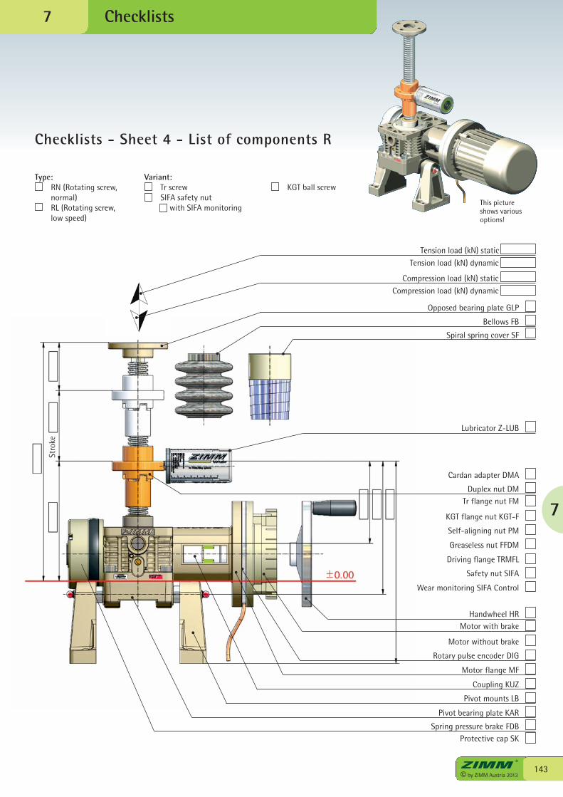
7
143© by ZIMM Austria 2013
Checklists
Checklists - Sheet 4 - List of components R
7
This pictureshows variousoptions!
Tension load (kN) static
Tension load (kN) dynamic
Compression load (kN) static
Compression load (kN) dynamic
Opposed bearing plate GLP
Bellows FB
Spiral spring cover SF
Lubricator Z-LUB
Cardan adapter DMA
Duplex nut DMTr flange nut FM
KGT flange nut KGT-F
Self-aligning nut PM
Greaseless nut FFDM
Driving flange TRMFL
Safety nut SIFA
Wear monitoring SIFA Control
Handwheel HRMotor with brake
Motor without brake
Rotary pulse encoder DIG
Motor flange MF
Coupling KUZ
Pivot mounts LB
Pivot bearing plate KAR
Spring pressure brake FDBProtective cap SK
Type: RN (Rotating screw,
normal) RL (Rotating screw,
low speed)
Variant: Tr screw SIFA safety nut with SIFA monitoring
KGT ball screw
Stro
ke
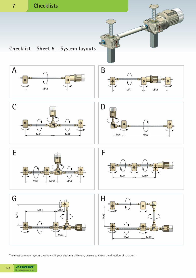
© by ZIMM Austria 2013144
Checklists7
Checklist - Sheet 5 - System layouts
A
C
E
G
B
D
F
H
The most common layouts are shown. If your design is different, be sure to check the direction of rotation!
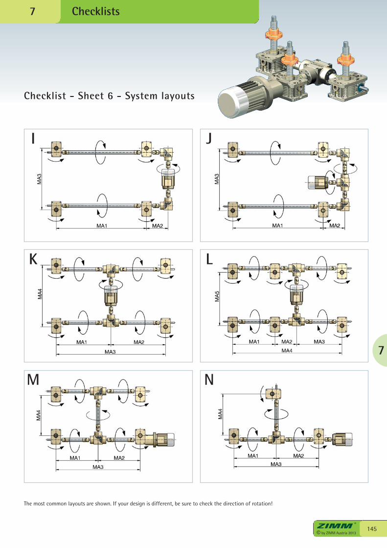
7
145© by ZIMM Austria 2013
Checklists
Checklist - Sheet 6 - System layouts
7
I
K
M
J
L
N
The most common layouts are shown. If your design is different, be sure to check the direction of rotation!

people and product...© by ZIMM Austria 2013
146

in harmony!
7
147© by ZIMM Austria 2013

© by ZIMM Austria 2013148
Installation, operation, inspection
Correct installation and commissioning is important for reliable operation of the system. Good maintenance is a precondition for a long service life.
Please therefore study the Instruction Manual which are supplied with each delivery and are also available for downloading from: www.zimm.at
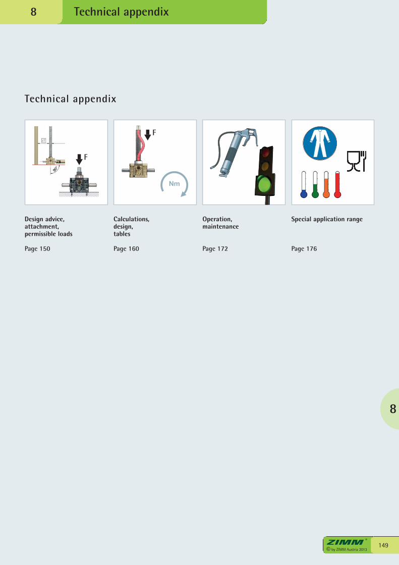
Technical appendix
Design advice,attachment,permissible loads
Page 150
Calculations,design,tables
Page 160
3© ZIMM Austria 2012
Technical appendix
149© by ZIMM Austria 2013
8
8
Operation, maintenance
Page 172
Special application range
Page 176
F
F
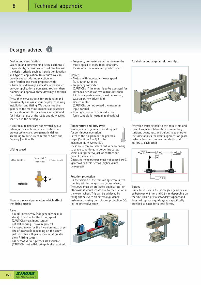
© by ZIMM Austria 2013150
Technical appendix8
Design advice
Parallelism and angular relationships
Attention must be paid to the parallelism andcorrect angular relationships of mountingsurfaces, gears, nuts and guides to each other.The same applies for exact alignment of gears,pedestal bearings, connecting shafts andmotors to each other.
GuidesGuide bush play in the screw jack gearbox canbe between 0.2 mm and 0.6 mm depending onthe size. This is just a secondary support anddoes not replace a guide system specificallyprovided to cater for lateral forces.
- Frequency converter serves to increase themotor speed to more than 1500 rpm.
Please note the maximum gearbox speed.
Slower:- Motors with more poles/lower speed
(6, 8, 10 or 12 poles)- Frequency converter
(CAUTION: if the motor is to be operated forextended periods at frequencies less than 25 Hz, adequate cooling must be assured,e.g.: separately driven fan)
- Geared motor (CAUTION: do not exceed the maximuminput torque)
- Bevel gearbox with gear reduction(only suitable for certain applications)
Temperature and duty cycleScrew jacks are generally not designedfor continuous operation. Refer to the diagram on the gearboxpages (Sections 2 + 3) for themaximum duty cycles (ED). These are reference values but vary accordingto usage conditions. In borderline cases,select a larger screw jack or contact ourproject technicians. Operating temperatures must not exceed 60°C(gearbox) or 80°C (screw) (higher valueson request).
Rotation protectionOn the version S, the translating screw is freerunning within the gearbox (worm wheel). The screw must be protected against rotation –otherwise it would rotate due to the friction inthe worm wheel. This can be achieved byfixing the screw to an external guidancesystem or by using our rotation protection (VS)(in the protective tube).
Design and specificationSelection and dimensioning is the customer’sresponsibility, because we are not familiar withthe design criteria such as installation locationand type of application. On request we canprovide support during selection andspecification and make proposals withsubassembly drawings and calculations basedon your application parameters. You can thenexamine and approve these drawings and theirparts lists.These then serve as basis for production andpreassembly and assist your employees duringinstallation and fitting. We guarantee thequality of the machine elements as describedin the catalogue. The gearboxes are designedfor industrial use at the loads and duty cyclesspecified in the catalogue.
If your requirements are not covered by ourcatalogue descriptions, please contact ourproject technicians. We generally deliveraccording to our current Terms of Sales andDelivery (Section 10).
Lifting speed
There are several parameters which affectthe lifting speed:
Faster:- double-pitch screw (not generally held in stock): This doubles the lifting speed (CAUTION: max. input torque, not self-locking - brake required!)- increased screw for the R version (next larger
size of gearbox): depending on the screwjack size, this will give a somewhat greaterpitch / lifting speed
- Ball screw: Various pitches are available (CAUTION: not self-locking– brake required!)
m/minV
Lifting speed v =Screw pitch PGear ratio i
x motor speed n
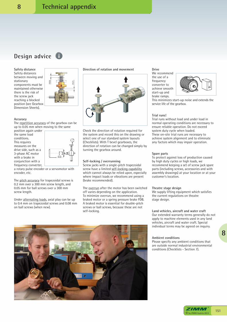
8
151© by ZIMM Austria 2013
Technical appendix
Design advice
8
Direction of rotation and movement
Check the direction of rotation required forthe system and record this on the drawing orselect one of our standard system layouts(Checklists). With T bevel gearboxes, thedirection of rotation can be changed simply byturning the gearbox around.
Self-locking / overrunningScrew jacks with a single-pitch trapezoidalscrew have a limited self-locking capabilitywhich cannot always be relied upon, especiallywhere impact loads or vibrations are present(brake recommended).
The overrun after the motor has been switchedoff varies depending on the application.To minimize overrun, we recommend using abraked motor or a spring pressure brake FDB.A braked motor is essential for double-pitchscrews or ball screws, because these are notself-locking.
Safety distanceSafety distancesbetween moving andstationarycomponents must bemaintained otherwisethere is the risk ofthe screw jackreaching a blockedposition (see GearboxDimension Sheets).
AccuracyThe repetition accuracy of the gearbox can beup to 0.05 mm when moving to the sameposition again underthe same loadconditions. This requiresmeasures on thedrive side, such as a3-phase AC motorwith a brake inconjunction with afrequency converter,a rotary pulse encoder or a servomotor withencoder, etc.
The pitch accuracy for trapezoidal screws is 0.2 mm over a 300 mm screw length, and0.05 mm for ball screws over a 300 mm screw length.
Under alternating loads, axial play can be upto 0.4 mm on trapezoidal screws and 0.08 mmon ball screws (when new).
DriveWe recommendthe use of afrequencyconverter toachieve smoothstart-up andbrake ramps. This minimizes start-up noise and extends theservice life of the gearbox.
Trial runs!Trial runs without load and under load innormal operating conditions are necessary toensure reliable operation. Do not exceedsystem duty cycle when loaded. These on-site trial runs are necessary toachieve system alignment and to eliminateany factors which may impair operation.
Spare partsTo protect against loss of production causedby high duty cycles or high loads, werecommend keeping a set of screw jack spareparts (including screws, accessories and withassembly drawings) at your location or at yourcustomer’s location.
Theatre stage designWe supply lifting equipment which satisfiesthe current regulations on theatre stage design.
Land vehicles, aircraft and water craftOur extended warranty terms generally do notapply to machine elements used in any landvehicles, aircraft and water craft. Specialindividual terms may be agreed on inquiry.
Ambient conditionsPlease specify any ambient conditions that are outside normal industrial environmentalconditions (Checklists - Section 7).
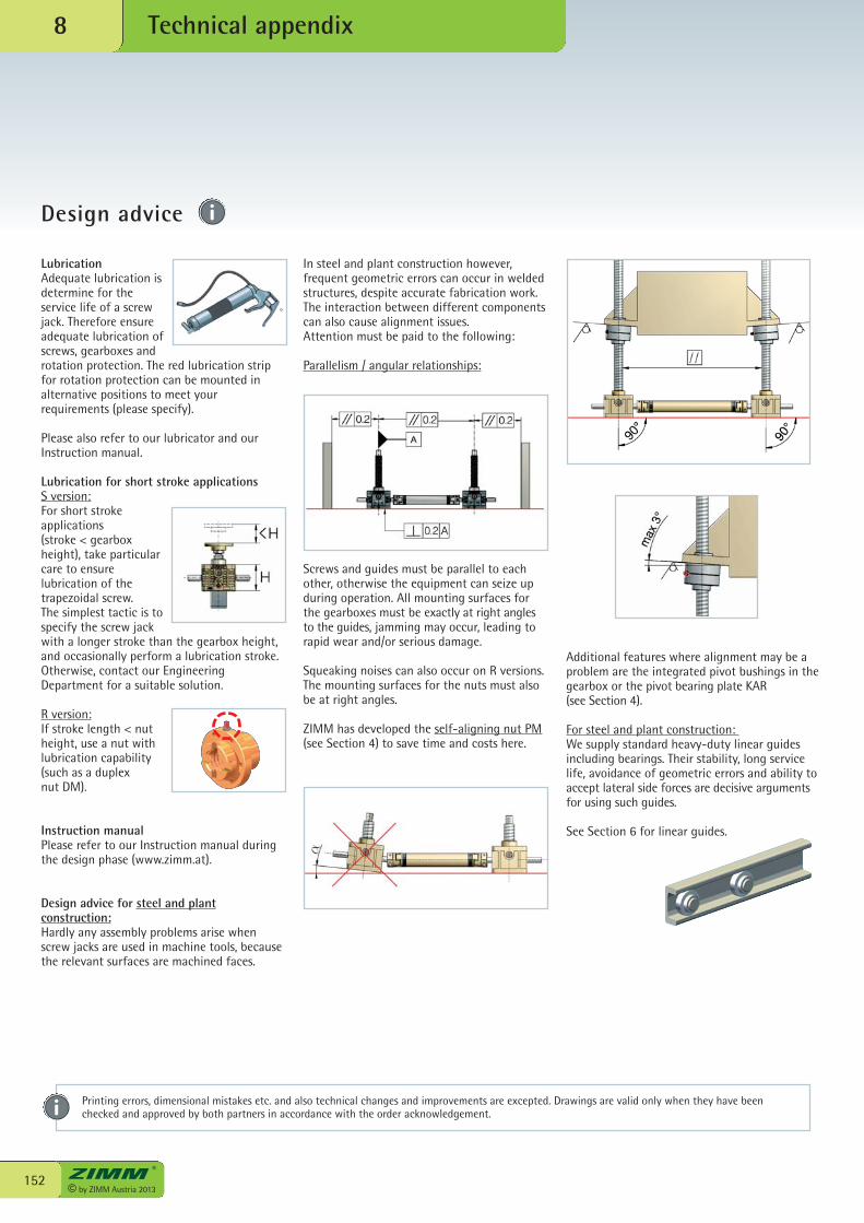
© by ZIMM Austria 2013152
Technical appendix8
Design advice
Additional features where alignment may be aproblem are the integrated pivot bushings in thegearbox or the pivot bearing plate KAR(see Section 4).
For steel and plant construction: We supply standard heavy-duty linear guidesincluding bearings. Their stability, long servicelife, avoidance of geometric errors and ability toaccept lateral side forces are decisive argumentsfor using such guides.
See Section 6 for linear guides.
LubricationAdequate lubrication isdetermine for theservice life of a screwjack. Therefore ensureadequate lubrication ofscrews, gearboxes androtation protection. The red lubrication stripfor rotation protection can be mounted inalternative positions to meet yourrequirements (please specify).
Please also refer to our lubricator and ourInstruction manual.
Lubrication for short stroke applicationsS version:For short strokeapplications (stroke < gearboxheight), take particularcare to ensurelubrication of thetrapezoidal screw. The simplest tactic is tospecify the screw jackwith a longer stroke than the gearbox height,and occasionally perform a lubrication stroke.Otherwise, contact our EngineeringDepartment for a suitable solution.
R version:If stroke length < nutheight, use a nut withlubrication capability(such as a duplexnut DM).
Instruction manualPlease refer to our Instruction manual duringthe design phase (www.zimm.at).
Design advice for steel and plantconstruction:Hardly any assembly problems arise whenscrew jacks are used in machine tools, becausethe relevant surfaces are machined faces.
In steel and plant construction however,frequent geometric errors can occur in weldedstructures, despite accurate fabrication work.The interaction between different componentscan also cause alignment issues.Attention must be paid to the following:
Parallelism / angular relationships:
Screws and guides must be parallel to eachother, otherwise the equipment can seize upduring operation. All mounting surfaces forthe gearboxes must be exactly at right anglesto the guides, jamming may occur, leading torapid wear and/or serious damage.
Squeaking noises can also occur on R versions.The mounting surfaces for the nuts must alsobe at right angles.
ZIMM has developed the self-aligning nut PM(see Section 4) to save time and costs here.
Printing errors, dimensional mistakes etc. and also technical changes and improvements are excepted. Drawings are valid only when they have beenchecked and approved by both partners in accordance with the order acknowledgement.
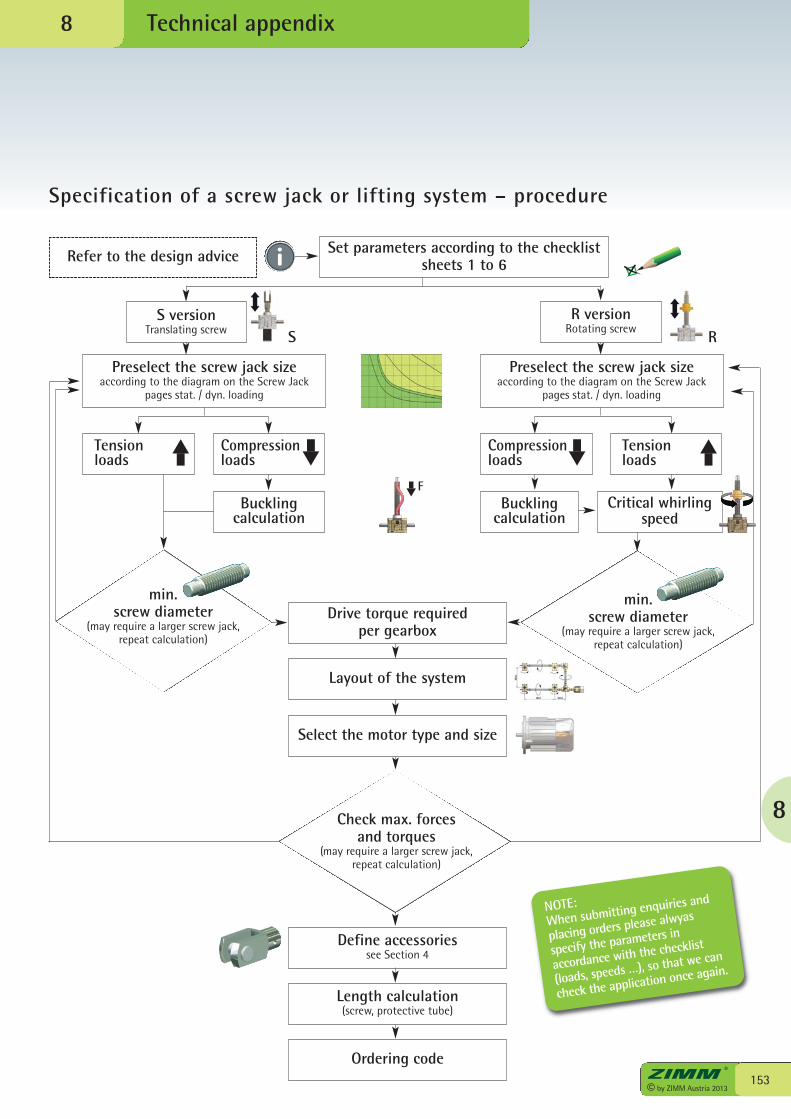
8
153© by ZIMM Austria 2013
Technical appendix
Specification of a screw jack or lifting system – procedure
8
Refer to the design advice
R versionRotating screw
Set parameters according to the checklist sheets 1 to 6
Preselect the screw jack sizeaccording to the diagram on the Screw Jack
pages stat. / dyn. loading
Tensionloads
Compressionloads
Buckling calculation
Compressionloads
Tensionloads
Critical whirlingspeed
Buckling calculation
Preselect the screw jack sizeaccording to the diagram on the Screw Jack
pages stat. / dyn. loading
min.screw diameter
(may require a larger screw jack, repeat calculation)
S versionTranslating screw RS
Check max. forcesand torques
(may require a larger screw jack, repeat calculation)
Drive torque requiredper gearbox
Layout of the system
Define accessoriessee Section 4
Length calculation(screw, protective tube)
Ordering code
Select the motor type and size
min. screw diameter
(may require a larger screw jack, repeat calculation)
F
NOTE:When submitting enquiries and
placing orders please alwyas
specify the parameters in
accordance with the checklist
(loads, speeds …), so that we can
check the application once again.
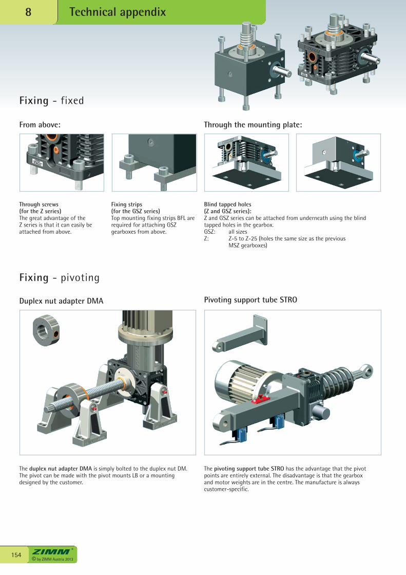
© by ZIMM Austria 2013154
Technical appendix8
Fixing - fixed
Fixing - pivoting
From above: Through the mounting plate:
Through screws (for the Z series)The great advantage of the Z series is that it can easily beattached from above.
Fixing strips(for the GSZ series)Top mounting fixing strips BFL arerequired for attaching GSZgearboxes from above.
Blind tapped holes (Z and GSZ series):Z and GSZ series can be attached from underneath using the blindtapped holes in the gearbox.GSZ: all sizesZ: Z-5 to Z-25 (holes the same size as the previous
MSZ gearboxes)
Duplex nut adapter DMA Pivoting support tube STRO
The duplex nut adapter DMA is simply bolted to the duplex nut DM.The pivot can be made with the pivot mounts LB or a mountingdesigned by the customer.
The pivoting support tube STRO has the advantage that the pivotpoints are entirely external. The disadvantage is that the gearboxand motor weights are in the centre. The manufacture is alwayscustomer-specific.
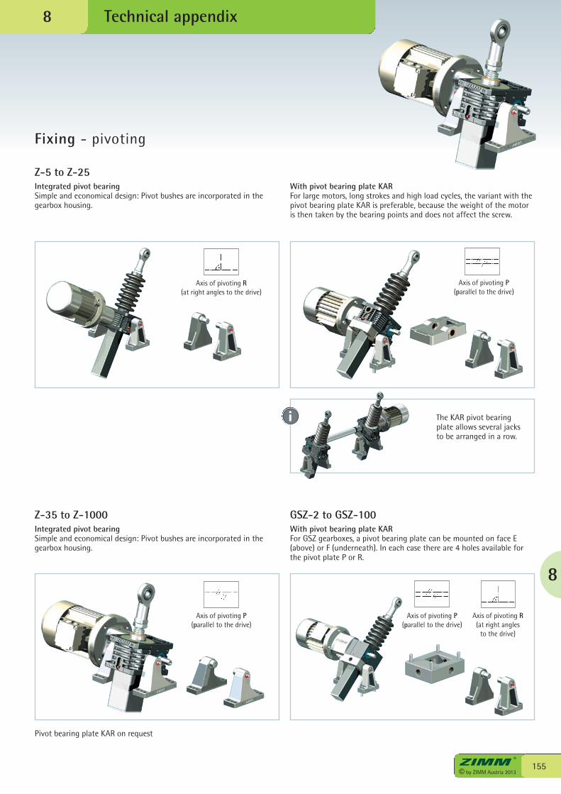
8
155© by ZIMM Austria 2013
Technical appendix
Fixing - pivoting
Z-5 to Z-25Integrated pivot bearingSimple and economical design: Pivot bushes are incorporated in thegearbox housing.
Axis of pivoting R(at right angles to the drive)
With pivot bearing plate KARFor large motors, long strokes and high load cycles, the variant with thepivot bearing plate KAR is preferable, because the weight of the motoris then taken by the bearing points and does not affect the screw.
Axis of pivoting P(parallel to the drive)
8
The KAR pivot bearingplate allows several jacksto be arranged in a row.
Z-35 to Z-1000Integrated pivot bearingSimple and economical design: Pivot bushes are incorporated in thegearbox housing.
Pivot bearing plate KAR on request
Axis of pivoting P(parallel to the drive)
GSZ-2 to GSZ-100With pivot bearing plate KARFor GSZ gearboxes, a pivot bearing plate can be mounted on face E(above) or F (underneath). In each case there are 4 holes available forthe pivot plate P or R.
Axis of pivoting P(parallel to the drive)
Axis of pivoting R(at right angles
to the drive)
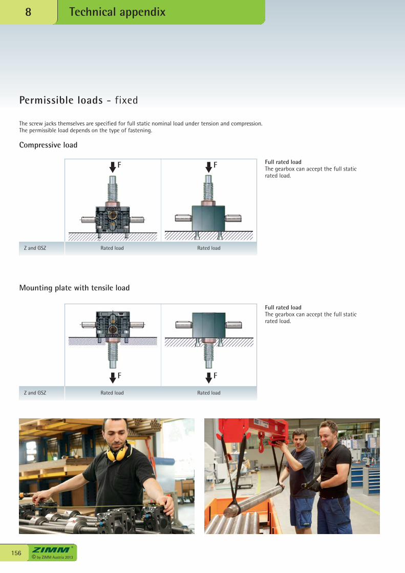
© by ZIMM Austria 2013156
Technical appendix8
Permissible loads - fixed
The screw jacks themselves are specified for full static nominal load under tension and compression. The permissible load depends on the type of fastening.
Compressive load
Full rated loadThe gearbox can accept the full staticrated load.
Mounting plate with tensile load
Full rated loadThe gearbox can accept the full staticrated load.
F F
F F
Z and GSZ Rated load Rated load
Z and GSZ Rated load Rated load
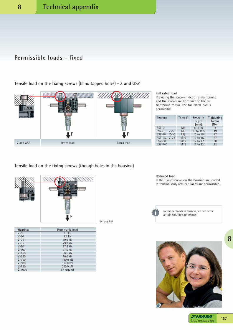
8
157© by ZIMM Austria 2013
Technical appendix
Permissible loads - fixed
8
Tensile load on the fixing screws (blind tapped holes) - Z and GSZ
Tensile load on the fixing screws (though holes in the housing)
Full rated loadProviding the screw-in depth is maintainedand the screws are tightened to the fulltightening torque, the full rated load ispermissible.
Reduced loadIf the fixing screws on the housing are loadedin tension, only reduced loads are permissible.
Gearbox Permissible loadZ-5 2.5 kNZ-10 3.5 kNZ-25 10.0 kNZ-35 29.8 kNZ-50 27.5 kNZ-100 27.0 kNZ-150 56.5 kNZ-250 70.0 kNZ-350 180.0 kNZ-500 110.0 kNZ-750 210.0 kNZ-1000 on request
For higher loads in tension, we can offercertain solutions on request.F
Z and GSZ Rated load Rated load
F F
Screws 8.8
Gearbox Thread* Screw-in Tightening depth torque [mm] [Nm]GSZ-2 M6 8 to 10 8GSZ-5, Z-5 M8 10 to 11.5 19GSZ-10, Z-10 M8 10 to 15 17GSZ-25, Z-25 M10 12 to 15 27GSZ-50 M12 12 to 17 38GSZ-100 M16 16 to 22 82
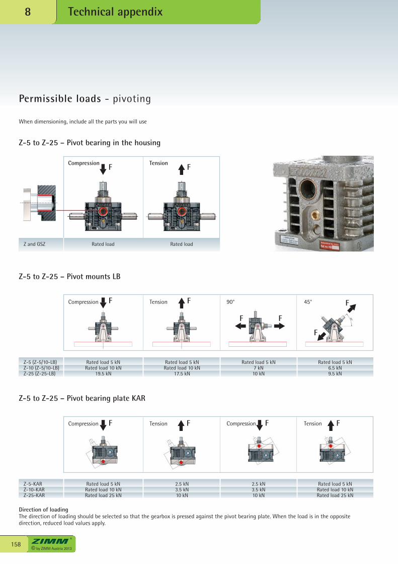
© by ZIMM Austria 2013158
Technical appendix8
Permissible loads - pivoting
When dimensioning, include all the parts you will use
Z-5 to Z-25 – Pivot bearing in the housing
Z-5 to Z-25 – Pivot mounts LB
Direction of loadingThe direction of loading should be selected so that the gearbox is pressed against the pivot bearing plate. When the load is in the oppositedirection, reduced load values apply.
Z-5 (Z-5/10-LB)Z-10 (Z-5/10-LB)Z-25 (Z-25-LB)
Rated load 5 kNRated load 10 kN
19.5 kN
Rated load 5 kN6.5 kN9.5 kN
Rated load 5 kN7 kN10 kN
Rated load 5 kNRated load 10 kN
17.5 kN
90° 45°TensionCompression
Z-5 to Z-25 – Pivot bearing plate KAR
Z-5-KARZ-10-KARZ-25-KAR
Rated load 5 kNRated load 10 kNRated load 25 kN
Rated load 5 kNRated load 10 kNRated load 25 kN
2.5 kN3.5 kN10 kN
2.5 kN3.5 kN10 kN
Compression TensionTensionCompression F F F F
F F
FF
F
F
F FCompression Tension
Z and GSZ Rated load Rated load
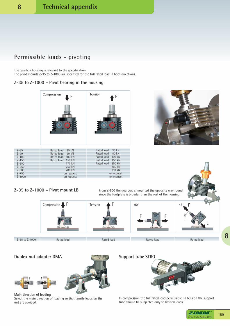
8
159© by ZIMM Austria 2013
Technical appendix
Permissible loads - pivoting
Z-35 to Z-1000 – Pivot mount LB
Duplex nut adapter DMA Support tube STRO
Z-35 to Z-1000 Rated load Rated loadRated loadRated load
90° 45°TensionCompression
The gearbox housing is relevant to the specification. The pivot mounts Z-35 to Z-1000 are specified for the full rated load in both directions.
Z-35 to Z-1000 – Pivot bearing in the housing
From Z-500 the gearbox is mounted the opposite way round,since the footplate is broader than the rest of the housing:
8
In compression the full rated load permissible. In tension the supporttube should be subjected only to limited loads.
FF
Main direction of loadingSelect the main direction of loading so that tensile loads on thenut are avoided.
F F
FF F
F
Compression Tension
Z-35Z-50Z-100Z-150Z-250Z-350Z-500Z-750Z-1000
Rated load 35 kNRated load 50 kNRated load 100 kNRated load 150 kN
177 kN250 kN280 kN
on requeston request
Rated load 35 kNRated load 50 kNRated load 100 kNRated load 150 kNRated load 250 kN
260 kN310 kN
on requeston request
F F
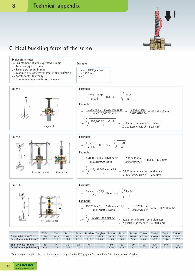
© by ZIMM Austria 2013160
Technical appendix8
Critical buckling force of the screw
I = = 55,610.7396 mm445,000 N x 3 x (1,320 mm x 0.7)2
π2 x 210,000 N/mm2
1.1525912 mm4
2,072,616.924=
I = then d =F x v x (L x 2)2
π2 x EI x 64π
4
I = = 453,965.22 mm445,000 N x 3 x (1,320 mm x 2)2
π2 x 210,000 N/mm2
9.089611 mm4
2,072,616.924
d = = 55.15 mm minimum core diameter= Z-250 (screw core Ø = 59.6 mm)
453,965.22 mm4 x 64π
4
I = then d =F x v x L2
π2 x EI x 64π
4
d = = 38.99 mm minimum core diameter= Z-100 (screw core Ø = 43.6 mm)
113,491.305 mm4 x 64π
4
I = then d =F x v x (L x 0.7)2
π2 x EI x 64π
4
d = = 32.62 mm minimum core diameter= Z-50/Tr50 (screw core Ø = 39.8 mm)
55,610.739 mm4 x 64π
4
Formula:
Example:
Formula:
Example:
Formula:
Example:
=
I = = 113,491.305 mm445,000 N x 3 x (1,320 mm)2
π2 x 210,000 N/mm2
2.3522411 mm4
2,072,616.924=
Euler 1
unguided
S version guided Pivot drive
Euler 2
R version guided
Euler 3
Example:
F = 45,000N/gearboxL = 1320 mmv = 3
Explanatory notes:I = 2nd moment of area expressed in mm4
F = Max. load/gearbox in N L = Free screw length in mm E = Modulus of elasticity for steel (210,000N/mm2) v = Safety factor (normally 3)d = Minimum core diameter of the screw
F
GSZ-2 Z-5 Z-10 Z-25 Z-35/50 Z-50/Tr50 Z-100 Z-150 Z-250 Z-350 Z-500 Z-750 Z-1000Trapezoidal screw Tr 16x4 18x4 20x4 30x6 40x7 50x8 55x9 60x9 80x16 100x16 120x16 140x20 160x20Core Ø in mm (minimum) 10.9 12.9 14.9 22.1 31.0 39.8 43.6 48.6 59.6 80.6 99.6 115.0 135.0
Ball screw KGT Ø mm 16 16 25 32 40 - 50 63 80 100 125 140 160Core Ø in mm (minimum*) 12.9 12.9 21.5 27.3 34.1 - 43.6 51.8 67 87.4 107.8 117 132.8
*Depending on the pitch, the core Ø may be even larger. See the KGT pages in Sections 2 and 3 for the exact core Ø values.
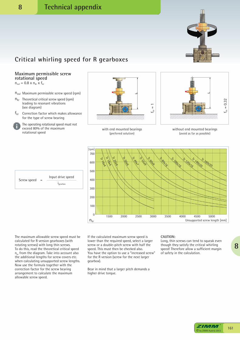
Maximum permissible screwrotational speednzul = 0.8 x nkr x fkr
nzul Maximum permissible screw speed (rpm)
nkr Theoretical critical screw speed (rpm) leading to resonant vibrations (see diagram)
fkr Correction factor which makes allowance for the type of screw bearing
The operating rotational speed must not exceed 80% of the maximum rotational speed
8
161© by ZIMM Austria 2013
Technical appendix
Critical whirling speed for R gearboxes
8
The maximum allowable screw speed must becalculated for R version gearboxes (withrotating screws) with long thin screws.To do this, read the theoretical critical speednkr from the diagram. Take into account alsothe additional lengths for screw covers etc.when calculating unsupported screw lengths.Now use the formula together with thecorrection factor for the screw bearingarrangement to calculate the maximumallowable screw speed.
If the calculated maximum screw speed islower than the required speed, select a largerscrew or a double-pitch screw with half thespeed. This must then be checked also.You have the option to use a “increased screw”for the R version (screw for the next largergearbox).
Bear in mind that a larger pitch demands ahigher drive torque.
CAUTION:Long, thin screws can tend to squeak eventhough they satisfy the critical whirling speed! Therefore allow a sufficient margin of safety in the calculation.
with end mounted bearings(preferred solution)
without end mounted bearings(avoid as far as possible)
Input drive speed
igearbox
Screw speed =
f kr=
1
f kr=
0.32
0
100
200
300
400
500
600
700[rpm]
1500 2000 2500 3000 3500 4000 4500 5000Unsupported screw length [mm]
Tr 18x4Tr 20x4
Tr 30x6
Tr 40x7Tr 55x9Tr 60x9
Tr 80x16
Tr 100x16
Tr 120x16
Tr 140x20
Tr 160x20
nkr
Tr 16x4
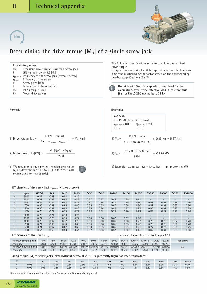
© by ZIMM Austria 2013162
Technical appendix8
Determining the drive torque [MG] of a single screw jack
ZNL
20.080.06
50.100.08
100.260.16
250.360.26
350.560.40
500.760.54
1001.681.02
1501.901.20
2502.641.94
3503.242.20
5003.962.84
7507.284.42
10009.705.90
Formula: Example:
1) Drive torque: MG = + ML [Nm]F [kN] . P [mm]
2 . π . ηgearbox . ηscrew
. i
MG [Nm] . n [rpm]
9550
1) MG = + 0.36 Nm = 5.97 Nm12 kN . 6 mm
2 . π . 0.87 . 0.391 . 6
2) PM = = 0.938 kW5.97 Nm . 1500 rpm
9550
3) Example: 0.938 kW . 1.5 = 1.407 kW motor 1.5 kW3) We recommend multiplying the calculated valueby a safety factor of 1.3 to 1.5 (up to 2 for smallsystems and for low speeds).
Z-25-SNF = 12 kN (dynamic lift load)ηgearbox = 0.87 ηscrew = 0.391P = 6 i = 6
Explanatory notes:MG necessary drive torque [Nm] for a screw jackF Lifting load (dynamic) [kN] ηgearbox Efficiency of the screw jack (without screw)ηscrew Efficiency of the screwP Screw pitch [mm] i Drive ratio of the screw jackML Idling torque [Nm]PM Motor drive power
i rpm GSZ-2 Z-5 Z-10 Z-25 Z-35 Z-50 Z-100 Z-150 Z-250 Z-350 Z-500 Z-750 Z-1000N 3000 0.87 0.81 0.83 0.87 - - - - - - - - -N 1500 0.87 0.82 0.84 0.87 0.87 0.87 0.88 0.89 0.91 - - - -N 1000 0.86 0.82 0.82 0.86 0.87 0.86 0.87 0.89 0.90 0.91 0.92 0.88 0.90N 750 0.86 0.82 0.84 0.85 0.86 0.85 0.87 0.88 0.90 0.91 0.92 0.88 0.90N 500 0.85 0.82 0.84 0.83 0.85 0.84 0.85 0.87 0.89 0.90 0.92 0.87 0.89N 100 0.74 0.77 0.79 0.78 0.78 0.78 0.78 0.80 0.83 0.86 0.87 0.81 0.84L 3000 0.78 0.74 0.78 0.76 - - - - - - - - -L 1500 0.77 0.70 0.74 0.72 0.64 0.66 0.67 0.67 0.78 - - - -L 1000 0.75 0.67 0.72 0.70 0.64 0.66 0.65 0.66 0.77 0.78 0.76 0.67 0.76L 750 0.74 0.65 0.70 0.68 0.64 0.66 0.65 0.65 0.76 0.78 0.75 0.66 0.76L 500 0.71 0.62 0.67 0.65 0.63 0.65 0.65 0.63 0.75 0.77 0.73 0.65 0.75L 100 0.54 0.53 0.59 0.54 0.52 0.55 0.57 0.53 0.65 0.67 0.61 0.58 0.66
2) Motor power: PM[kW] =
Efficiencies of the screw jack ηgearbox (without screw)
Efficiencies of the screws ηscrew calculated for coefficient of friction μ = 0.11
Idling torques ML of screw jacks [Nm] (without screw, at 20°C - significantly higher at low temperatures)
The following specifications serve to calculate the requireddrive torque. For gearboxes with single-pitch trapezoidal screws the load cansimply be multiplied by the factor stated on the correspondinggearbox page (Sections 2 + 3).
Use at least 10% of the gearbox rated load for thecalculation, even if the effective load is less than this(i.e. for the Z-250 use at least 25 kN).
Tr screw, single-pitch 16x4 18x4 20x4 30x6 40x7 50x8 55x9 60x9 80x16 100x16 120x16 140x20 160x20 Ball screwEfficiency 0.453 0.420 0.391 0.391 0.357 0.335 0.340 0.320 0.391 0.335 0.293 0.308 0.278 Tr screw, double-pitch 16x8P4 18x8P4 20x8P4 30x12P6 40x14P7 50x16P8 55x18P9 60x18P9 80x32P16 100x32P16 120x32P16 140x40P20 160x40P20 0.9Efficiency 0.623 0.591 0.563 0.563 0.526 0.502 0.508 0.484 0.563 0.502 0.453 0.471 0.436
These are indicative values for calculation. Series production models may vary!
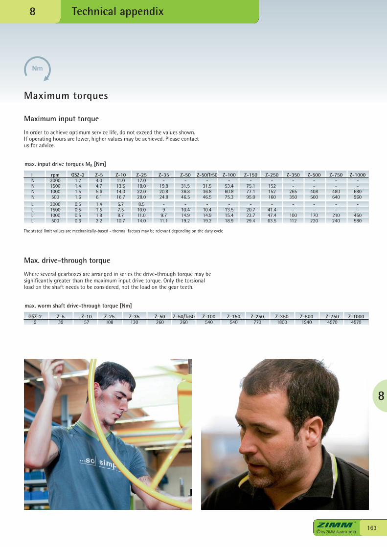
8
163© by ZIMM Austria 2013
Technical appendix
Maximum torques
8
Maximum input torque
In order to achieve optimum service life, do not exceed the values shown.If operating hours are lower, higher values may be achieved. Please contactus for advice.
The stated limit values are mechanically-based - thermal factors may be relevant depending on the duty cycle
i rpm GSZ-2 Z-5 Z-10 Z-25 Z-35 Z-50 Z-50/Tr50 Z-100 Z-150 Z-250 Z-350 Z-500 Z-750 Z-1000N 3000 1.2 4.0 11.0 17.0 - - - - - - - - - -N 1500 1.4 4.7 13.5 18.0 19.8 31.5 31.5 53.4 75.1 152 - - - -N 1000 1.5 5.6 14.0 22.0 20.8 36.8 36.8 60.8 77.1 152 265 408 480 680N 500 1.6 6.1 16.7 28.0 24.8 46.5 46.5 75.3 95.0 160 350 500 640 960L 3000 0.5 1.4 5.7 8.5 - - - - - - - - - -L 1500 0.5 1.5 7.5 10.0 9 10.4 10.4 13.5 20.7 41.4 - - - -L 1000 0.5 1.8 8.7 11.0 9.7 14.9 14.9 15.4 23.7 47.4 100 170 210 450L 500 0.6 2.2 10.7 14.0 11.1 19.2 19.2 18.9 29.4 63.5 112 220 240 580
max. input drive torques MR [Nm]
Max. drive-through torque
Where several gearboxes are arranged in series the drive-through torque may besignificantly greater than the maximum input drive torque. Only the torsionalload on the shaft needs to be considered, not the load on the gear teeth.
GSZ-2 Z-5 Z-10 Z-25 Z-35 Z-50 Z-50/Tr50 Z-100 Z-150 Z-250 Z-350 Z-500 Z-750 Z-1000 9 39 57 108 130 260 260 540 540 770 1800 1940 4570 4570
max. worm shaft drive-through torque [Nm]
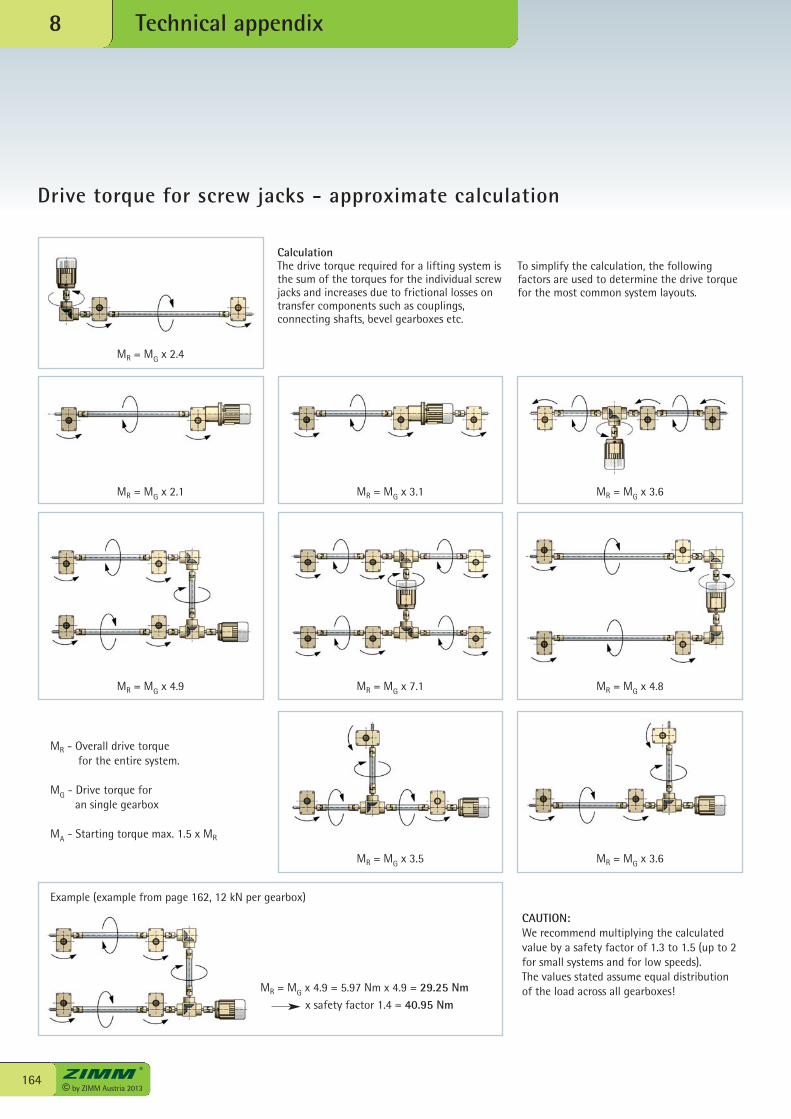
© by ZIMM Austria 2013164
Technical appendix8
Drive torque for screw jacks - approximate calculation
CAUTION:We recommend multiplying the calculatedvalue by a safety factor of 1.3 to 1.5 (up to 2for small systems and for low speeds).The values stated assume equal distributionof the load across all gearboxes!
MR - Overall drive torquefor the entire system.
MG - Drive torque foran single gearbox
MA - Starting torque max. 1.5 x MR
Example (example from page 162, 12 kN per gearbox)
MR = MG x 4.9 = 5.97 Nm x 4.9 = 29.25 Nm x safety factor 1.4 = 40.95 Nm
MR = MG x 2.4
MR = MG x 2.1 MR = MG x 3.1 MR = MG x 3.6
MR = MG x 4.9 MR = MG x 7.1 MR = MG x 4.8
MR = MG x 3.5 MR = MG x 3.6
CalculationThe drive torque required for a lifting system isthe sum of the torques for the individual screwjacks and increases due to frictional losses ontransfer components such as couplings,connecting shafts, bevel gearboxes etc.
To simplify the calculation, the followingfactors are used to determine the drive torquefor the most common system layouts.
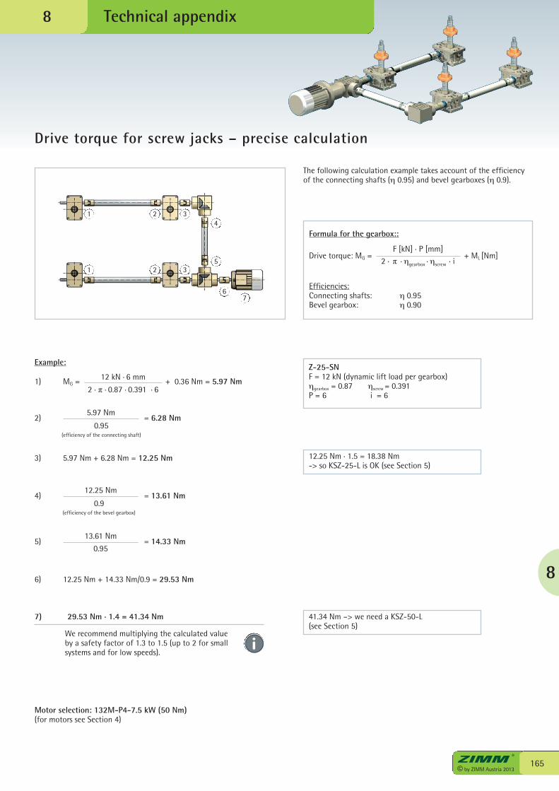
8
165© by ZIMM Austria 2013
Technical appendix
Drive torque for screw jacks – precise calculation
8
The following calculation example takes account of the efficiencyof the connecting shafts (η 0.95) and bevel gearboxes (η 0.9).
Drive torque: MG = + ML [Nm]F [kN] . P [mm]
2 . π . ηgearbox . ηscrew
. i
Example:
1) MG = + 0.36 Nm = 5.97 Nm12 kN . 6 mm
2 . π . 0.87 . 0.391 . 6
3) 5.97 Nm + 6.28 Nm = 12.25 Nm 12.25 Nm . 1.5 = 18.38 Nm-> so KSZ-25-L is OK (see Section 5)
41.34 Nm –> we need a KSZ-50-L(see Section 5)
Motor selection: 132M-P4-7.5 kW (50 Nm)(for motors see Section 4)
Z-25-SNF = 12 kN (dynamic lift load per gearbox)ηgearbox = 0.87 ηscrew = 0.391P = 6 i = 6
Formula for the gearbox::
Efficiencies:Connecting shafts: η 0.95Bevel gearbox: η 0.90
2) = 6.28 Nm5.97 Nm
0.95 (efficiency of the connecting shaft)
4) = 13.61 Nm12.25 Nm
0.9 (efficiency of the bevel gearbox)
5) = 14.33 Nm13.61 Nm
0.95
6) 12.25 Nm + 14.33 Nm/0.9 = 29.53 Nm
7) 29.53 Nm . 1.4 = 41.34 Nm
We recommend multiplying the calculated valueby a safety factor of 1.3 to 1.5 (up to 2 for smallsystems and for low speeds).
1
1
2
2
3
3
4
5
67
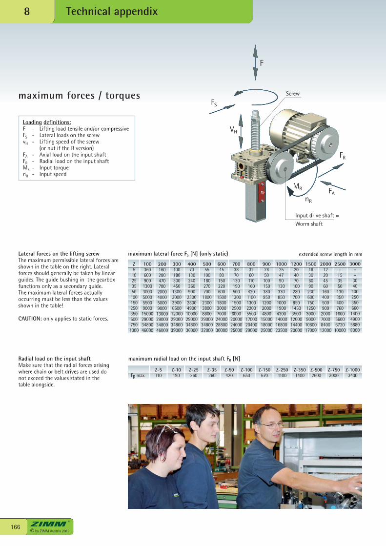
© by ZIMM Austria 2013166
Technical appendix8
maximum forces / torques
Loading definitions:F - Lifting load tensile and/or compressiveFS - Lateral loads on the screwvH - Lifting speed of the screw (or nut if the R version)FA - Axial load on the input shaftFR - Radial load on the input shaftMR - Input torquenR - Input speed
Lateral forces on the lifting screwThe maximum permissible lateral forces areshown in the table on the right. Lateralforces should generally be taken by linearguides. The guide bushing in the gearboxfunctions only as a secondary guide.The maximum lateral forces actuallyoccurring must be less than the valuesshown in the table!
CAUTION: only applies to static forces.
Radial load on the input shaftMake sure that the radial forces arisingwhere chain or belt drives are used donot exceed the values stated in thetable alongside.
Z-5 Z-10 Z-25 Z-35 Z-50 Z-100 Z-150 Z-250 Z-350 Z-500 Z-750 Z-1000FR max. 110 190 260 260 420 650 670 1100 1400 2600 3000 3400
200160280470700
200040005000900013000290003480046000
1003606009001300300050005500900015000290003480046000
Z5102535501001502503505007501000
300100180300450130030003900650012000290003480039000
40070
13024036090023002800490010000290003480036000
50055100180270700
1800230038008800290003480032000
60045801502206001500180030007000
240002880030000
7003870
1301905001300150025006000200002400025000
80032601101604201100130022005500170002040029000
9002850100150380950120020004800150001800025000
1000254790130330850100019004300140001680023500
120020407010028070085014503500120001440020000
1500183060902306007501250300090001080017000
20001220456016040050090020007000840012000
2500–15355013035040076016005600672010000
3000––30401002503506601400490058808000
maximum lateral force FS [N] (only static) extended screw length in mm
maximum radial load on the input shaft FR [N]
FS
F
FR
FAMR
nR
Screw
Input drive shaft =Worm shaft
VH
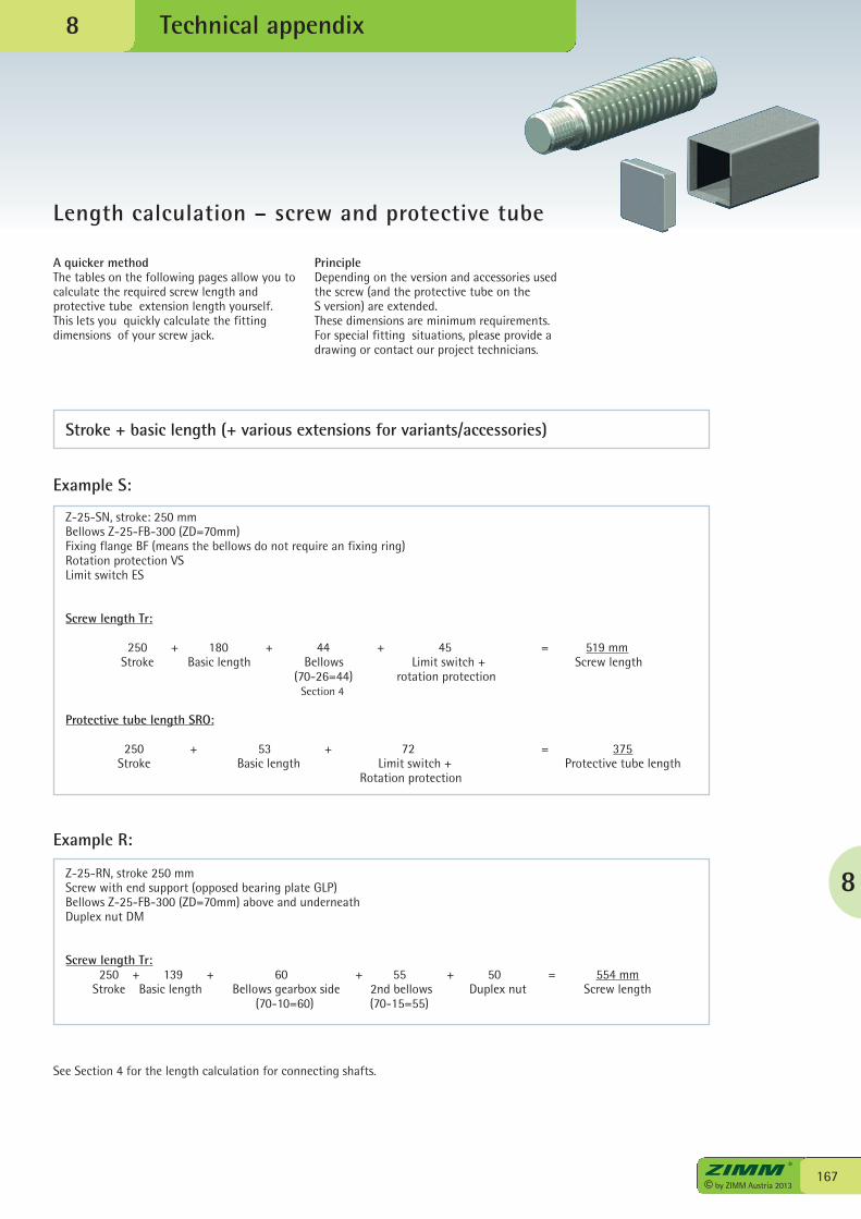
8
167© by ZIMM Austria 2013
Technical appendix
Length calculation – screw and protective tube
8
A quicker methodThe tables on the following pages allow you tocalculate the required screw length andprotective tube extension length yourself.This lets you quickly calculate the fittingdimensions of your screw jack.
PrincipleDepending on the version and accessories usedthe screw (and the protective tube on the S version) are extended.These dimensions are minimum requirements.For special fitting situations, please provide adrawing or contact our project technicians.
Stroke + basic length (+ various extensions for variants/accessories)
Example S:
Z-25-SN, stroke: 250 mmBellows Z-25-FB-300 (ZD=70mm)Fixing flange BF (means the bellows do not require an fixing ring)Rotation protection VSLimit switch ES
Screw length Tr:
250 + 180 + 44 + 45 = 519 mmStroke Basic length Bellows Limit switch + Screw length
(70-26=44) rotation protection Section 4
Protective tube length SRO:
250 + 53 + 72 = 375Stroke Basic length Limit switch + Protective tube length
Rotation protection
Example R:
Z-25-RN, stroke 250 mmScrew with end support (opposed bearing plate GLP)Bellows Z-25-FB-300 (ZD=70mm) above and underneathDuplex nut DM
Screw length Tr:250 + 139 + 60 + 55 + 50 = 554 mm
Stroke Basic length Bellows gearbox side 2nd bellows Duplex nut Screw length(70-10=60) (70-15=55)
See Section 4 for the length calculation for connecting shafts.
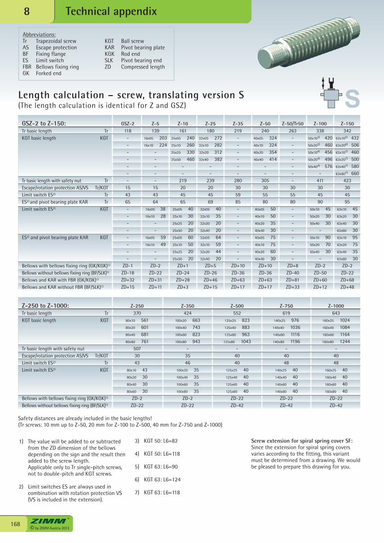
© by ZIMM Austria 2013168
Technical appendix8
Length calculation – screw, translating version S(The length calculation is identical for Z and GSZ)
1) The value will be added to or subtractedfrom the ZD dimension of the bellowsdepending on the sign and the result thenadded to the screw length. Applicable only to Tr single-pitch screws,not to double-pitch and KGT screws.
2) Limit switches ES are always used incombination with rotation protection VS(VS is included in the extension).
3) KGT 50: L6=82
4) KGT 50: L6=118
5) KGT 63: L6=90
6) KGT 63: L6=124
7) KGT 63: L6=118
Screw extension for spiral spring cover SF: Since the extension for spiral spring coversvaries according to the fitting, this variantmust be determined from a drawing. We wouldbe pleased to prepare this drawing for you.
Z-10161
25x05 24025x10 26025x25 33025x50 460
--
219204565
25x05 4025x10 3025x25 2025x50 2025x05 6025x10 5025x25 2025x50 20
ZD+1ZD-24ZD+28ZD+3
Z-25180
32x05 27232x10 28232x20 31232x40 382
--
239204569
32x05 4032x10 3532x20 2032x40 2032x05 6432x10 5932x20 4432x40 20
ZD+5ZD-26ZD+46ZD+15
Z-35219
------
280305985--------
ZD+10ZD-36ZD+63ZD+17
Z-50240
40x05 32440x10 32440x20 35440x40 414
--
305305580
40x05 5040x10 5040x20 3540x40 3040x05 7540x10 7540x20 6040x40 30
ZD+10ZD-36ZD+63ZD+17
Z-50/Tr50263
-------
305580--------
ZD+8ZD-40ZD+81ZD+33
Z-100338
50x103) 42050x203) 46050x104) 45650x204) 49650x404) 576
-411304590
50x10 4550x20 3050x40 30
-50x10 9050x20 7050x40 30
-ZD-2ZD-50ZD+60ZD+12
Z-150342
63x105) 43263x206) 50663x107) 46063x207) 50063x407) 58063x607) 660
423304595
63x10 4563x20 3063x40 3063x60 3063x10 9563x20 7563x40 3563x60 30
ZD-2ZD-22ZD+68ZD+48
Z-350424
100x20 663100x40 743100x60 823100x80 943
-3546
100x20 35100x40 35100x60 35100x80 35
ZD-2ZD-22
Z-500552
125x25 823125x40 883125x60 963
125x80 1043-
4040
125x25 40125x40 40125x60 40125x80 40
ZD-22ZD-42
Z-750619
140x25 976140x40 1036140x60 1116140x80 1196
-4048
140x25 40140x40 40140x60 40140x80 40
ZD-22ZD-42
Z-1000643
160x25 1024160x40 1084160x60 1164160x80 1244
-4048
160x25 40160x40 40160x60 40160x80 40
ZD-22ZD-42
GSZ-2118-------
154365--------
ZD-1ZD-18ZD+32ZD+15
Z-5139
16x05 20316x10 224
-----
154364
16x05 3816x10 28
--
16x05 5916x10 49
--
ZD-2ZD-22ZD+31ZD+11
Z-250 to Z-1000:Tr basic length TrKGT basic length KGT
Tr basic length with safety nutEscape/rotation protection AS/VS Tr/KGTLimit switch ES2) TrLimit switch ES2) KGT
Bellows with bellows fixing ring (GK/KGK)1)
Bellows without bellows fixing ring (BF/SLK)1)
GSZ-2 to Z-150:Tr basic length TrKGT basic length KGT
Tr basic length with safety nut TrEscape/rotation protection AS/VS Tr/KGTLimit switch ES2) TrES2) and pivot bearing plate KAR TrLimit switch ES2) KGT
ES2) and pivot bearing plate KAR KGT
Bellows with bellows fixing ring (GK/KGK)1)
Bellows without bellows fixing ring (BF/SLK)1)
Bellows and KAR with FBR (GK/KGK)1)
Bellows and KAR without FBR (BF/SLK)1)
Z-250370
80x10 56180x20 60180x40 68180x60 761
5073043
80x10 4380x20 3080x40 3080x60 30
ZD-2ZD-22
Safety distances are already included in the basic lengths! (Tr screws: 10 mm up to Z-50, 20 mm for Z-100 to Z-500, 40 mm for Z-750 and Z-1000)
Abbreviations: Tr Trapezoidal screw KGT Ball screwAS Escape protection KAR Pivot bearing plateBF Fixing flange KGK Rod endES Limit switch SLK Pivot bearing endFBR Bellows fixing ring ZD Compressed lengthGK Forked end
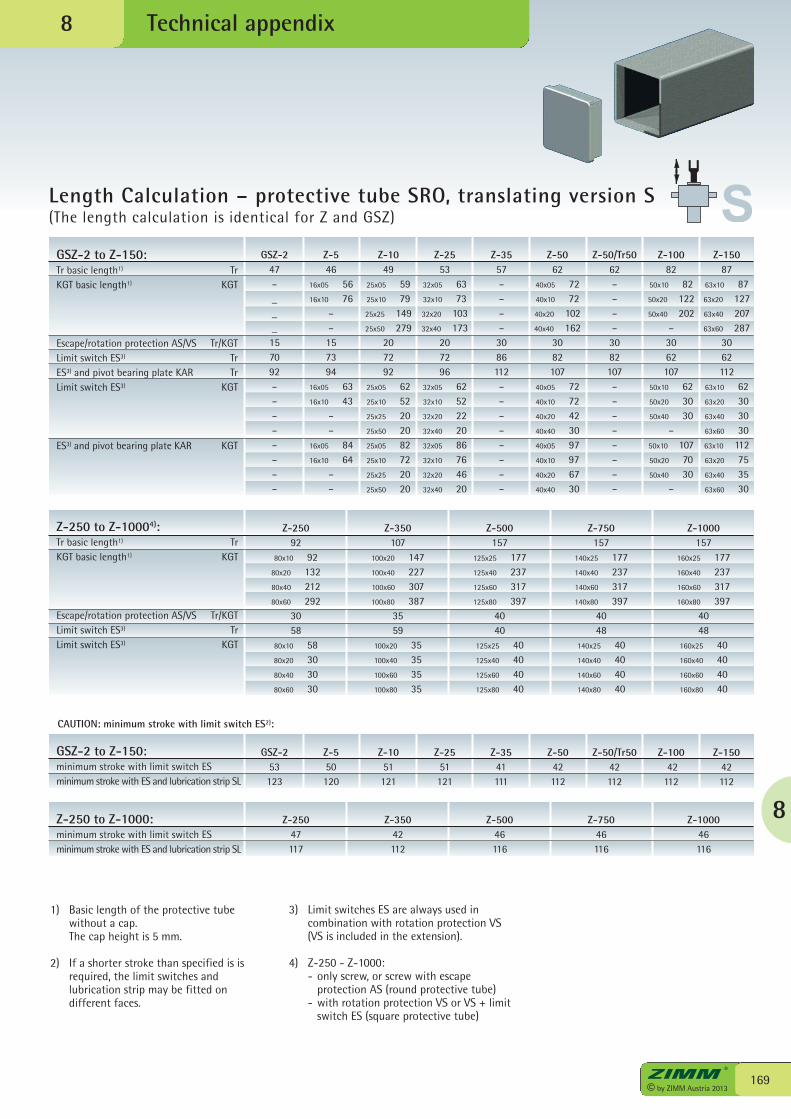
8
169© by ZIMM Austria 2013
Technical appendix
Length Calculation – protective tube SRO, translating version S(The length calculation is identical for Z and GSZ)
8
1) Basic length of the protective tubewithout a cap.
The cap height is 5 mm.
2) If a shorter stroke than specified is isrequired, the limit switches andlubrication strip may be fitted on different faces.
3) Limit switches ES are always used incombination with rotation protection VS(VS is included in the extension).
4) Z-250 - Z-1000: - only screw, or screw with escape
protection AS (round protective tube) - with rotation protection VS or VS + limit
switch ES (square protective tube)
GSZ-247–___157092––––––––
Z-546
16x05 5616x10 76
––157394
16x05 6316x10 43
––
16x05 8416x10 64
––
Z-1049
25x05 5925x10 7925x25 14925x50 279
207292
25x05 6225x10 5225x25 2025x50 2025x05 8225x10 7225x25 2025x50 20
Z-2553
32x05 6332x10 7332x20 10332x40 173
207296
32x05 6232x10 5232x20 2232x40 2032x05 8632x10 7632x20 4632x40 20
Z-3557––––3086112––––––––
Z-5062
40x05 7240x10 7240x20 10240x40 162
3082107
40x05 7240x10 7240x20 4240x40 3040x05 9740x10 9740x20 6740x40 30
Z-50/Tr5062––––3082107––––––––
Z-10082
50x10 8250x20 12250x40 202
–3062107
50x10 6250x20 3050x40 30
–50x10 10750x20 7050x40 30
–
Z-15087
63x10 8763x20 12763x40 20763x60 287
3062112
63x10 6263x20 3063x40 3063x60 3063x10 11263x20 7563x40 3563x60 30
GSZ-2 to Z-150:minimum stroke with limit switch ESminimum stroke with ES and lubrication strip SL
GSZ-253123
Z-1051121
Z-2551121
Z-3541111
Z-5042112
Z-50/Tr5042112
Z-10042
112
Z-15042112
Z-550120
Z-25092
80x10 9280x20 13280x40 21280x60 292
3058
80x10 5880x20 3080x40 3080x60 30
Z-350107
100x20 147100x40 227100x60 307100x80 387
3559
100x20 35100x40 35100x60 35100x80 35
Z-500157
125x25 177125x40 237125x60 317125x80 397
4040
125x25 40125x40 40125x60 40125x80 40
Z-750157
140x25 177140x40 237140x60 317140x80 397
4048
140x25 40140x40 40140x60 40140x80 40
Z-1000157
160x25 177160x40 237160x60 317160x80 397
4048
160x25 40160x40 40160x60 40160x80 40
Z-250 to Z-1000:minimum stroke with limit switch ESminimum stroke with ES and lubrication strip SL
CAUTION: minimum stroke with limit switch ES2):
Z-25047117
Z-35042112
Z-50046116
Z-75046116
Z-100046116
Z-250 to Z-10004):Tr basic length1) TrKGT basic length1) KGT
Escape/rotation protection AS/VS Tr/KGTLimit switch ES3) TrLimit switch ES3) KGT
GSZ-2 to Z-150:Tr basic length1) TrKGT basic length1) KGT
Escape/rotation protection AS/VS Tr/KGTLimit switch ES3) TrES3) and pivot bearing plate KAR TrLimit switch ES3) KGT
ES3) and pivot bearing plate KAR KGT
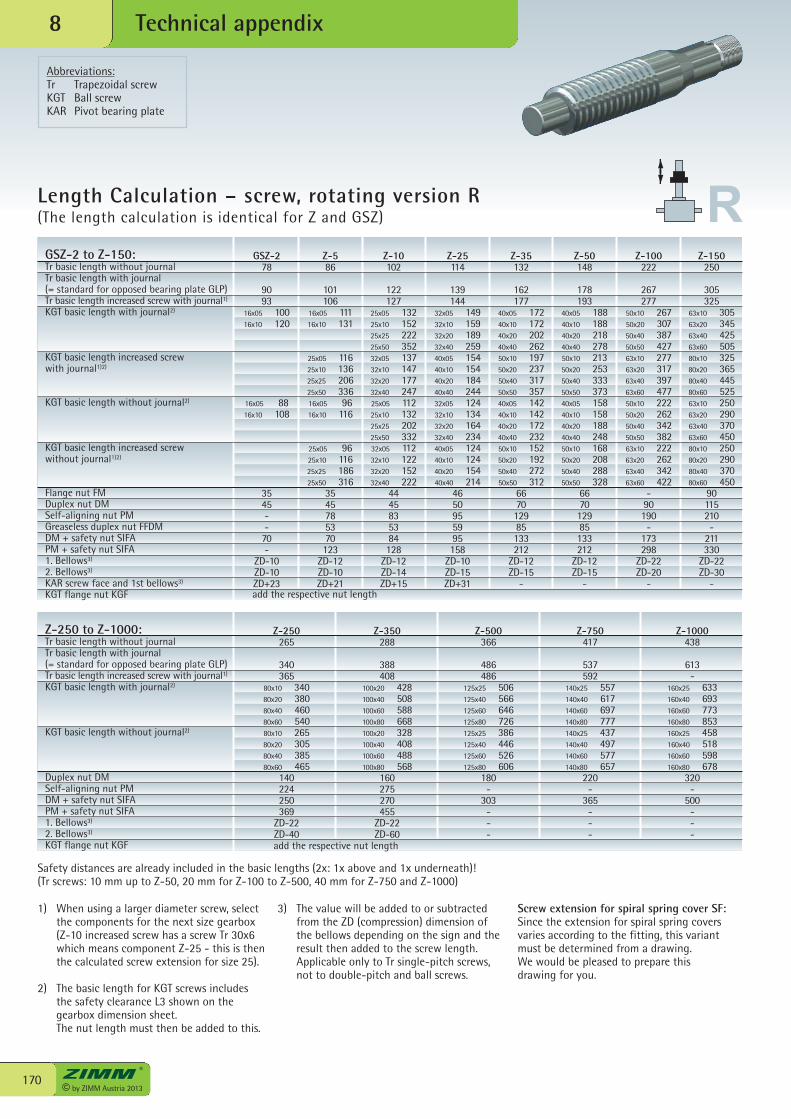
© by ZIMM Austria 2013170
Technical appendix8
Length Calculation – screw, rotating version R(The length calculation is identical for Z and GSZ)
3) The value will be added to or subtractedfrom the ZD (compression) dimension ofthe bellows depending on the sign and theresult then added to the screw length.
Applicable only to Tr single-pitch screws,not to double-pitch and ball screws.
1) When using a larger diameter screw, selectthe components for the next size gearbox(Z-10 increased screw has a screw Tr 30x6which means component Z-25 - this is thenthe calculated screw extension for size 25).
2) The basic length for KGT screws includesthe safety clearance L3 shown on thegearbox dimension sheet.
The nut length must then be added to this.
Z-100222
267277
50x10 26750x20 30750x40 38750x50 42763x10 27763x20 31763x40 39763x60 47750x10 22250x20 26250x40 34250x50 38263x10 22263x20 26263x40 34263x60 422
-90190
-173298
ZD-22ZD-20
-
Z-50148
178193
40x05 18840x10 18840x20 21840x40 27850x10 21350x20 25350x40 33350x50 37340x05 15840x10 15840x20 18840x40 24850x10 16850x20 20850x40 28850x50 328
667012985133212
ZD-12ZD-15
-
Z-35132
162177
40x05 17240x10 17240x20 20240x40 26250x10 19750x20 23750x40 31750x50 35740x05 14240x10 14240x20 17240x40 23250x10 15250x20 19250x40 27250x50 312
667012985133212
ZD-12ZD-15
-
Z-25114
139144
32x05 14932x10 15932x20 18932x40 25940x05 15440x10 15440x20 18440x40 24432x05 12432x10 13432x20 16432x40 23440x05 12440x10 12440x20 15440x40 214
4650955995158
ZD-10ZD-15ZD+31
Z-10102
122127
25x05 13225x10 15225x25 22225x50 35232x05 13732x10 14732x20 17732x40 24725x05 11225x10 13225x25 20225x50 33232x05 11232x10 12232x20 15232x40 222
4445835384128
ZD-12ZD-14ZD+15
GSZ-278
9093
16x05 10016x10 120
16x05 8816x10 108
3545--
70-
ZD-10ZD-10ZD+23
Z-586
101106
16x05 11116x10 131
25x05 11625x10 13625x25 20625x50 33616x05 9616x10 116
25x05 9625x10 11625x25 18625x50 316
3545785370123
ZD-12ZD-10ZD+21
Z-150250
305325
63x10 30563x20 34563x40 42563x60 50580x10 32580x20 36580x40 44580x60 52563x10 25063x20 29063x40 37063x60 45080x10 25080x20 29080x40 37080x60 450
90115210-
211330
ZD-22ZD-30
-
Z-1000438
613-
160x25 633160x40 693160x60 773160x80 853160x25 458160x40 518160x60 598160x80 678
320-
500---
Z-750417
537592
140x25 557140x40 617140x60 697140x80 777140x25 437140x40 497140x60 577140x80 657
220-
365---
Z-500366
486486
125x25 506125x40 566125x60 646125x80 726125x25 386125x40 446125x60 526125x80 606
180-
303---
Z-350288
388408
100x20 428100x40 508100x60 588100x80 668100x20 328100x40 408100x60 488100x80 568
160275270455
ZD-22ZD-60
Z-250265
340365
80x10 34080x20 38080x40 46080x60 54080x10 26580x20 30580x40 38580x60 465
140224250369
ZD-22ZD-40
GSZ-2 to Z-150:Tr basic length without journalTr basic length with journal (= standard for opposed bearing plate GLP)Tr basic length increased screw with journal1)
KGT basic length with journal2)
KGT basic length increased screw with journal1)2)
KGT basic length without journal2)
KGT basic length increased screw without journal1)2)
Flange nut FMDuplex nut DMSelf-aligning nut PMGreaseless duplex nut FFDMDM + safety nut SIFAPM + safety nut SIFA1. Bellows3)
2. Bellows3)
KAR screw face and 1st bellows3)
KGT flange nut KGF
Z-250 to Z-1000:Tr basic length without journalTr basic length with journal (= standard for opposed bearing plate GLP)Tr basic length increased screw with journal1)
KGT basic length with journal2)
KGT basic length without journal2)
Duplex nut DMSelf-aligning nut PMDM + safety nut SIFAPM + safety nut SIFA1. Bellows3)
2. Bellows3)
KGT flange nut KGF
Screw extension for spiral spring cover SF: Since the extension for spiral spring coversvaries according to the fitting, this variantmust be determined from a drawing.We would be pleased to prepare thisdrawing for you.
Safety distances are already included in the basic lengths (2x: 1x above and 1x underneath)!(Tr screws: 10 mm up to Z-50, 20 mm for Z-100 to Z-500, 40 mm for Z-750 and Z-1000)
add the respective nut length
add the respective nut length
Abbreviations: Tr Trapezoidal screw KGT Ball screw KAR Pivot bearing plate
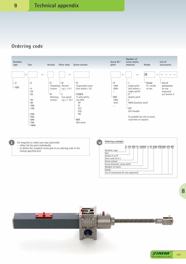
8
171© by ZIMM Austria 2013
Technical appendix
Ordering code
8
Gearbox type Size Version Drive ratio Screw version
Screw Ø /pitch
Number ofscrew starts,material Stroke
List ofaccessories
2
51025
3550100150
2503505007501000
STranslatingversion
RRotatingversion
NNormale.g. i = 4:1
LLow speede.g. i = 16:1
TrTrapezoidal screw(not stated = Tr)
Tr/SIFATr with safetynut SIFA OP EL ELV ELD NO
KGTBall screw
Tr18042004...
KGT16051610...
1single-pitch(not stated = single-pitch)2*double-pitchIINOX (stainless steel)
LH*left-handed
H
StrokeH + strokein mm
List ofaccessories(in anysequence)see Section 4
Z
GSZ
For enquiries or orders you may optionally:- either list the parts individually- or define the complete screw jack in an ordering code in the
format specified here
Ordering example:
Z-10-SN-Tr-2004-1-H 300-FB390-VS-BFGearbox, typeSizeVersion S or RDrive ratio N or LScrew versionScrew diameter, screw pitchNumber of startsStrokeList of accessories (in any sequence)
*is available but not ex stock. Lead time on request
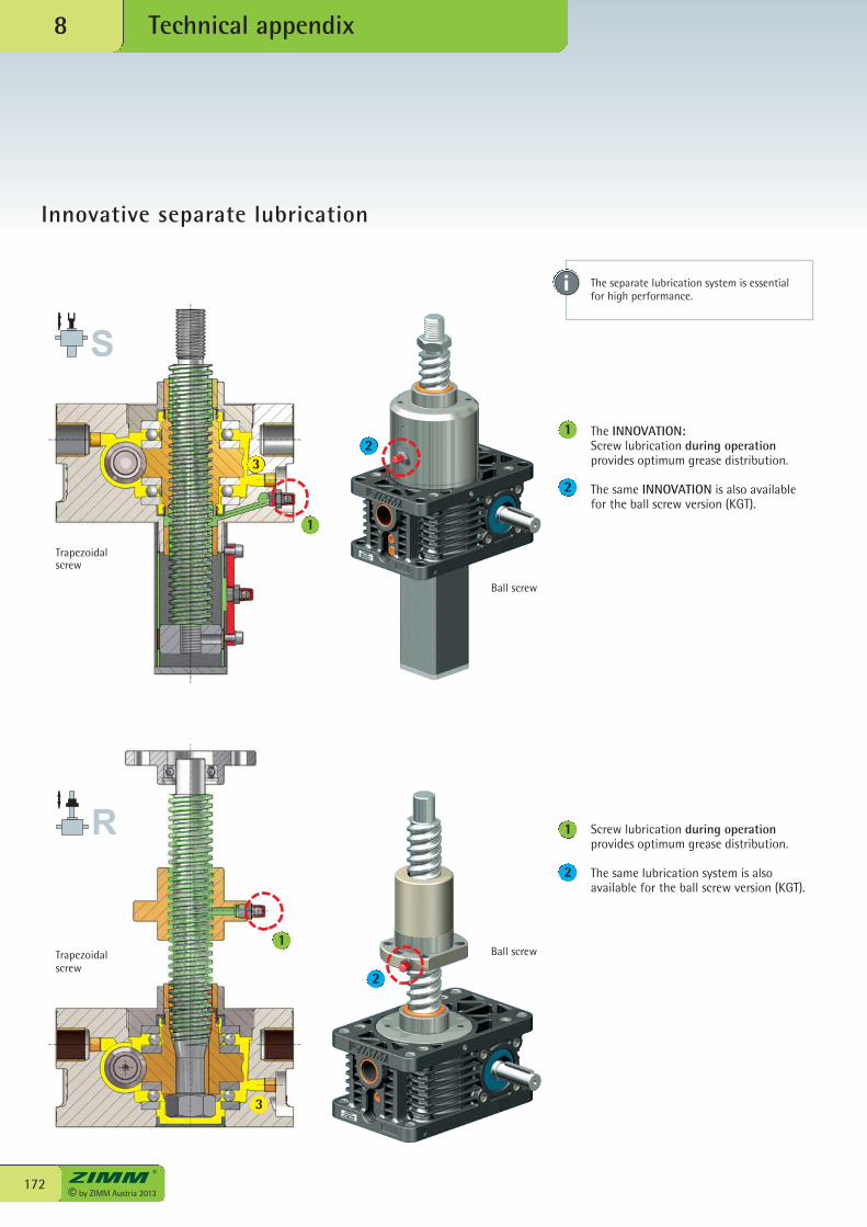
© by ZIMM Austria 2013172
Technical appendix8
Innovative separate lubrication
Trapezoidal screw
Trapezoidalscrew
Ball screw
Ball screw
Screw lubrication during operationprovides optimum grease distribution.
The same lubrication system is alsoavailable for the ball screw version (KGT).
The INNOVATION:Screw lubrication during operationprovides optimum grease distribution.
The same INNOVATION is also availablefor the ball screw version (KGT).
1
21
2
1
2
1
2
3
The separate lubrication system is essentialfor high performance.
3
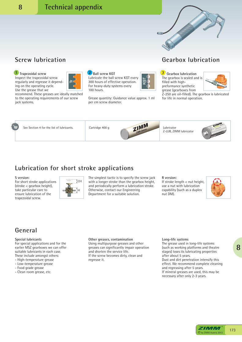
8
173© by ZIMM Austria 2013
Technical appendix
Screw lubrication
8
Gearbox lubrication
Gearbox lubricationThe gearbox is sealed and isfilled with high-preformance syntheticgrease (gearboxes from Z-250 are oil-filled). The gearbox is lubricatedfor life in normal operation.
3 Trapezoidal screwInspect the trapezoidal screwregularly and regrease it depend-ing on the operating cycle.Use the grease that werecommend. These greases are ideally matchedto the operating requirements of our screwjack systems.
Ball screw KGTLubricate the ball screw KGT every300 hours of effective operation.For heavy-duty systems every100 hours.
Grease quantity: Guidance value approx. 1 mlper cm screw diameter.
1 2
See Section 4 for the list of lubricants. LubricatorZ-LUB, ZIMM lubricator
Cartridge 400 g
Lubrication for short stroke applications
General
S version:For short stroke applications(stroke < gearbox height),take particular care to ensure lubrication of thetrapezoidal screw.
The simplest tactic is to specify the screw jackwith a longer stroke than the gearbox height,and periodically perform a lubrication stroke.Otherwise, contact our EngineeringDepartment for a suitable solution.
R version:If stroke length < nut height,use a nut with lubricationcapability (such as a duplexnut DM).
Special lubricantsFor special applications and for theearlier MSZ gearboxes we can offersuitable lubricants in each case. These include amongst others: - High-temperature grease- Low-temperature grease- Food grade grease- Clean room grease, etc.
Other greases, contaminationUsing multipurpose greases and other greases can significantly impair operation and shorten the service life.If the screw becomes dirty, clean and regrease it.
Long-life systemsThe grease used in long-life systems (such as working platforms and theatre stages) loses its lubricating properties after about 5 years.Dust and dirt penetration intensify this effect. We recommend complete cleaning and regreasing after 5 years.If mineral greases are used, this may benecessary after only 2-3 years.
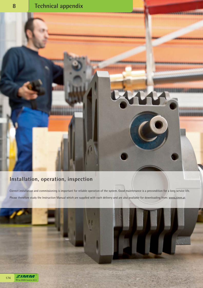
© by ZIMM Austria 2013174
Technical appendix8
Installation, operation, inspection
Correct installation and commissioning is important for reliable operation of the system. Good maintenance is a precondition for a long service life.
Please therefore study the Instruction Manual which are supplied with each delivery and are also available for downloading from: www.zimm.at
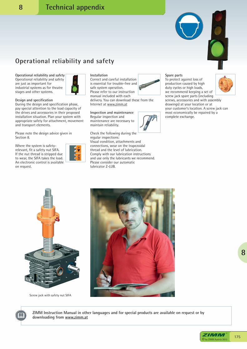
ZIMM Instruction Manual in other languages and for special products are available on request or bydownloading from www.zimm.at
8
175© by ZIMM Austria 2013
Technical appendix
Operational reliability and safety
8
Operational reliability and safetyOperational reliability and safetyare just as important forindustrial systems as for theatrestages and other systems.
Design and specificationDuring the design and specification phase,pay special attention to the load capacity ofthe drives and accessories in their proposedinstallation situation. Plan your system withappropriate safety for attachment, movementand transport elements.
Please note the design advice given inSection 8.
Where the system is safety-relevant, fit a safety nut SIFA.If the nut thread is stripped dueto wear, the SIFA takes the load.An electronic control is availableon request.
InstallationCorrect and careful installationis essential for trouble-free andsafe system operation. Please refer to our instructionmanual included with eachdelivery. You can download these from theInternet at www.zimm.at
Inspection and maintenanceRegular inspection andmaintenance are necessary tomaintain reliability.
Check the following during theregular inspections: Visual condition, attachments andconnections, wear on the trapezoidal thread and the level of lubrication.Comply with our lubrication instructionsand use only the lubricants we recommend.Please consider our automatic lubricator Z-LUB.
Spare partsTo protect against loss ofproduction caused by highduty cycles or high loads,we recommend keeping a set ofscrew jack spare parts (includingscrews, accessories and with assemblydrawings) at your location or atyour customer’s location. A screw jack canmost economically be repaired by acomplete exchange.
Screw jack with safety nut SIFA
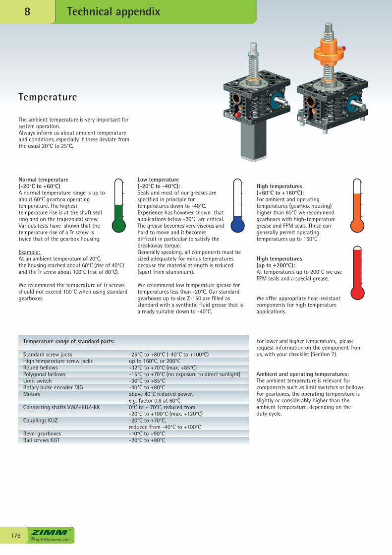
© by ZIMM Austria 2013176
Technical appendix8
Temperature
Normal temperature(-20°C to +60°C)A normal temperature range is up toabout 60°C gearbox operatingtemperature. The highesttemperature rise is at the shaft sealring and on the trapezoidal screw.Various tests have shown that thetemperature rise of a Tr screw istwice that of the gearbox housing.
Example: At an ambient temperature of 20°C,the housing reached about 60°C (rise of 40°C)and the Tr screw about 100°C (rise of 80°C).
We recommend the temperature of Tr screwsshould not exceed 100°C when using standardgearboxes.
Low temperature (-20°C to -40°C): Seals and most of our greases arespecified in principle fortemperatures down to -40°C.Experience has however shown thatapplications below -20°C are critical.The grease becomes very viscous andhard to move and it becomesdifficult in particular to satisfy thebreakaway torque.Generally speaking, all components must besized adequately for minus temperaturesbecause the material strength is reduced(apart from aluminium).
We recommend low temperature grease fortemperatures less than -20°C. Our standardgearboxes up to size Z-150 are filled asstandard with a synthetic fluid grease that isalready suitable down to -40°C.
High temperatures (+60°C to +160°C):For ambient and operatingtemperatures (gearbox housing)higher than 60°C we recommendgearboxes with high-temperaturegrease and FPM seals. These cangenerally permit operatingtemperatures up to 160°C.
High temperatures (up to +200°C):At temperatures up to 200°C we useFPM seals and a special grease.
We offer appropriate heat-resistantcomponents for high temperatureapplications.
Temperature range of standard parts:
Standard screw jacks -25°C to +80°C (-40°C to +100°C)High temperature screw jacks up to 160°C, or 200°CRound bellows -32°C to +70°C (max. +85°C)Polygonal bellows -15°C to +70°C (no exposure to direct sunlight)Limit switch -30°C to +85°CRotary pulse encoder DIG -40°C to +80°CMotors above 40°C reduced power, e.g. factor 0.8 at 60°CConnecting shafts VWZ+KUZ-KK 0°C to + 70°C, reduced from -20°C to +100°C (max. +120°C)Couplings KUZ -20°C to +70°C, reduced from -40°C to +100°CBevel gearboxes -10°C to +90°CBall screws KGT -20°C to +80°C
For lower and higher temperatures, pleaserequest information on the component fromus, with your checklist (Section 7).
Ambient and operating temperatures:The ambient temperature is relevant forcomponents such as limit switches or bellows.For gearboxes, the operating temperature isslightly or considerably higher than theambient temperature, depending on theduty cycle.
The ambient temperature is very important forsystem operation.Always inform us about ambient temperatureand conditions, especially if these deviate fromthe usual 20°C to 25°C.

8
177© by ZIMM Austria 2013
Technical appendix
Clean room
8
Food industry
Food industry sectorThe foodstuffs sector operates at a very highlevel of automation. On the one hand thispromotes a very high level of hygiene, on theother hand it permits intelligent and efficientsystems for economic production
Resistant against corrosionOur Z and GSZ series are corrosion-resistantand are therefore very suitable for mostapplications in the food industry. The GSZgearbox with its smooth surfaces isparticularly suitable. The Z and GSZ series are not suitable forspecial applications where stainless steelis mandatory.
Screw jack systemsWe supply gearboxes and systems with foodgrade grease to the food industry. Our foodgrade greases are FDA-approved. Use thechecklist in Section 7 to enquire about thesystem you require and also specify theparticular requirements for your application.
SectorsVarious fields such as semiconductorproduction, flat screen production, optical andlaser technology, spacecraft production etc.demand high cleanliness, which means thatclean room standards must be maintained.
Clean roomA clean room is a room where theconcentration of particles in the air iscontrolled and satisfies defined cleanlinessclasses. It is important to keep the particlecontamination caused by work materials,lubricants and drives to a minimum.
Your systemUse the checklist in Section 7 to enquire aboutthe system you require and also specify theparticular requirements for your application.We can then offer you a system to meet yourrequirements.
Resistant against corrosion
Corrosion-resistant as standard - no need for paintingAll relevant components of the ZIMM –Z series and GSZ series are coated as standardwith various single-layer and multi-layersystems resistant against corrosion.This eliminates the need for time-consumingand cost-intensive painting.
The colours black, anthracite and silver arevisually neutral and fit in with any colourcombination. The coating are speciallymatched to the various base materials andtheir functions. This ensures high-qualityprotection against corrosion for manyapplication areas.
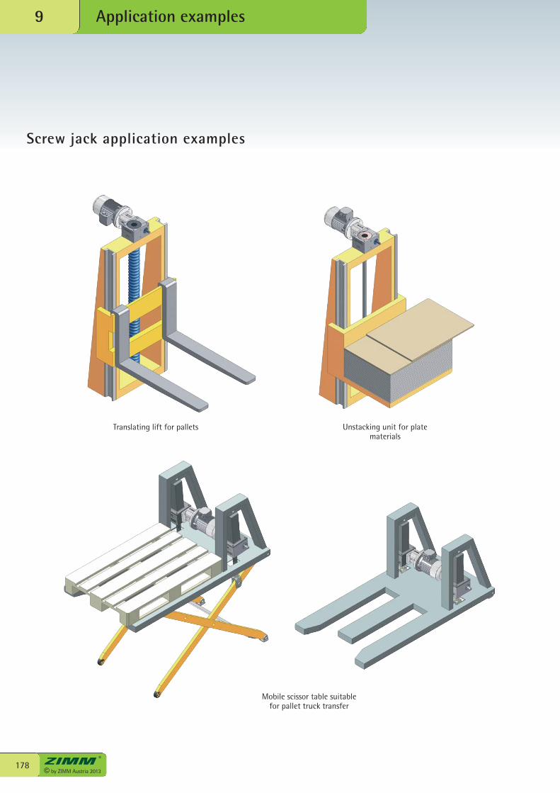
© by ZIMM Austria 2013178
Application examples9
Screw jack application examples
Unstacking unit for platematerials
Translating lift for pallets
Mobile scissor table suitable for pallet truck transfer
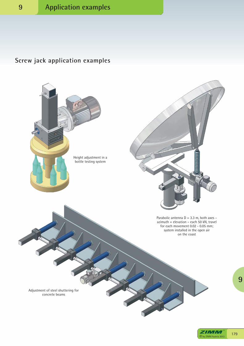
9
179© by ZIMM Austria 2013
Application examples
Screw jack application examples
9
Adjustment of steel shuttering forconcrete beams
Parabolic antenna D = 3.3 m, both axes –azimuth + elevation – each 50 kN, travel
for each movement 0.02 - 0.05 mm;system installed in the open air
on the coast
Height adjustment in abottle testing system
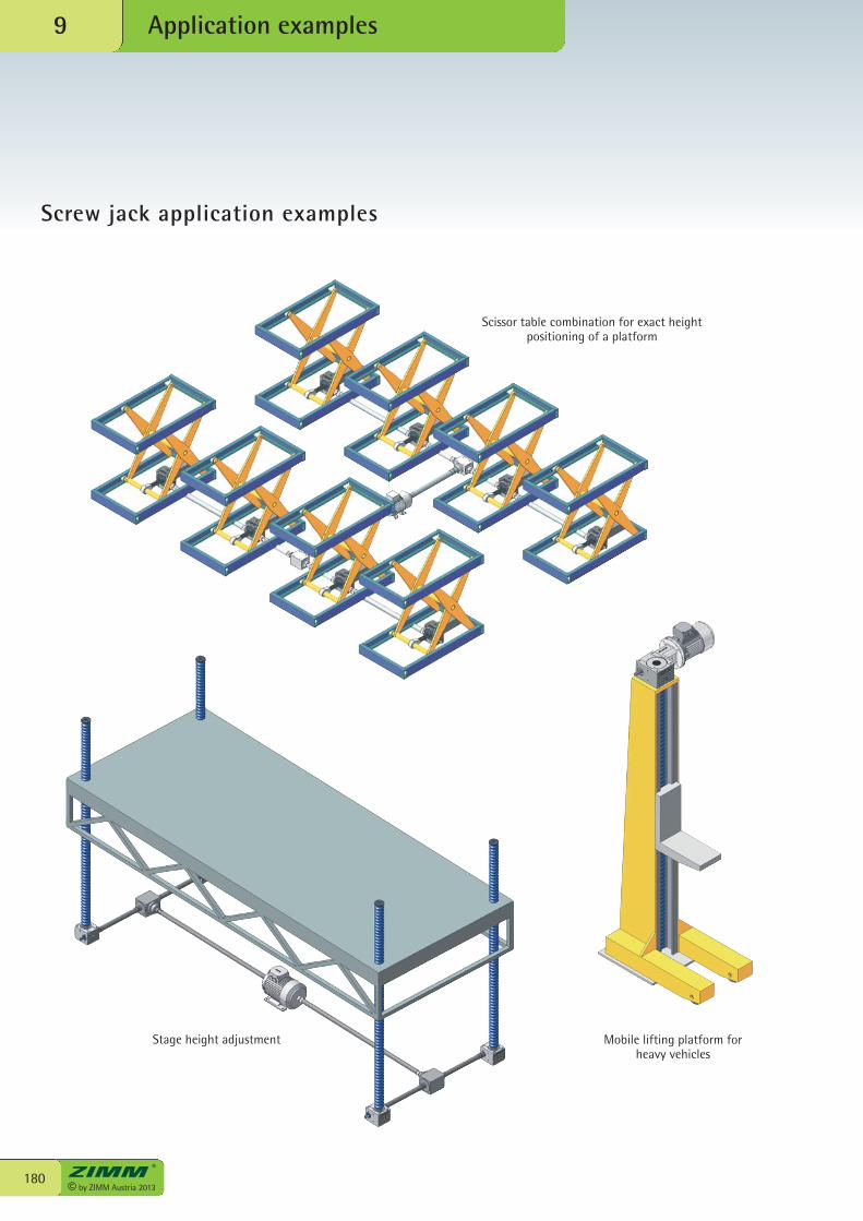
© by ZIMM Austria 2013180
Application examples9
Screw jack application examples
Stage height adjustment Mobile lifting platform forheavy vehicles
Scissor table combination for exact heightpositioning of a platform
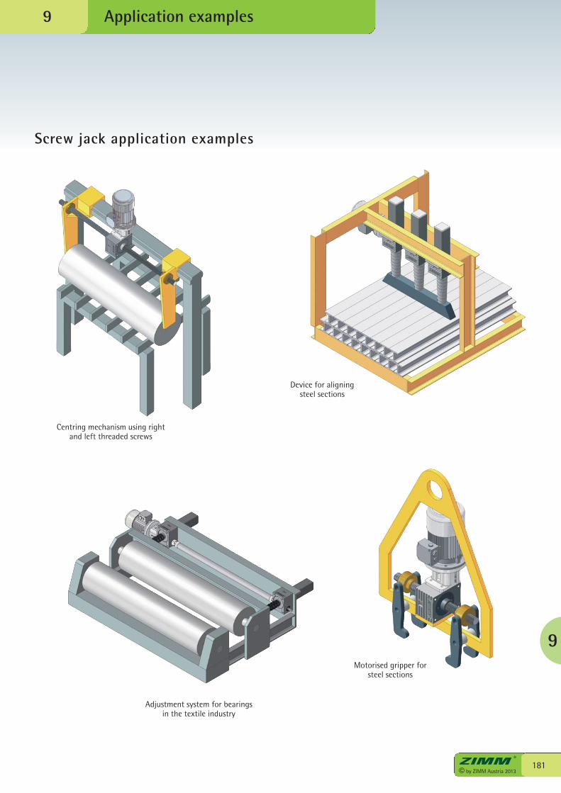
9
181© by ZIMM Austria 2013
Application examples
Screw jack application examples
9
Centring mechanism using rightand left threaded screws
Motorised gripper for steel sections
Adjustment system for bearingsin the textile industry
Device for aligning steel sections
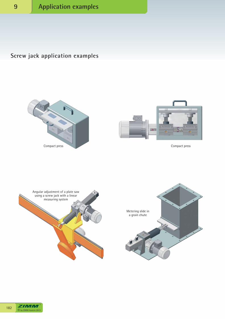
© by ZIMM Austria 2013182
Application examples9
Screw jack application examples
Compact press Compact press
Metering slide in a grain chute
Angular adjustment of a plate sawusing a screw jack with a linear
measuring system
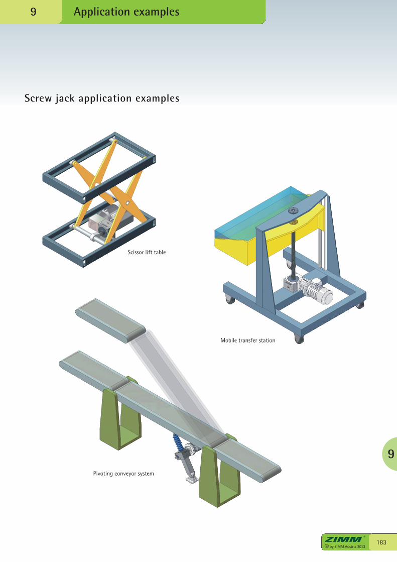
9
183© by ZIMM Austria 2013
Application examples
Screw jack application examples
9
Scissor lift table
Mobile transfer station
Pivoting conveyor system
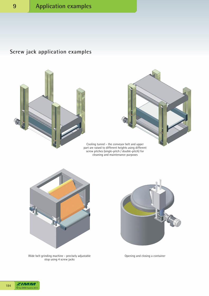
© by ZIMM Austria 2013184
Application examples9
Screw jack application examples
Cooling tunnel - the conveyor belt and upper part are raised to different heights using different
screw pitches (single-pitch / double-pitch) forcleaning and maintenance purposes
Wide belt grinding machine - precisely adjustablestop using 4 screw jacks
Opening and closing a container
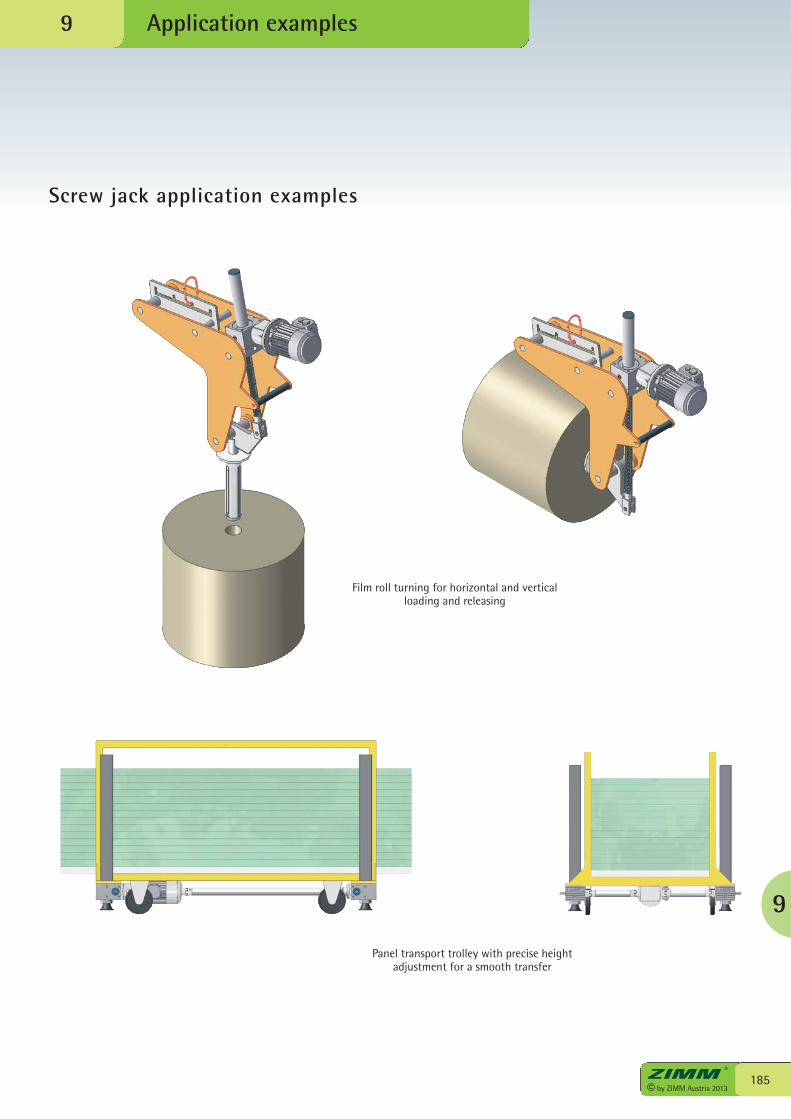
9
185© by ZIMM Austria 2013
Application examples
Screw jack application examples
9
Film roll turning for horizontal and verticalloading and releasing
Panel transport trolley with precise heightadjustment for a smooth transfer

left: Gunther Zimmermann (CEO)right: Jürgen Zimmermann (Company founder)
Tradition and modernityall under one roof
We place great value on creative freedom andthe courage to pursue new ideas. Our companylocation at Lustenau in the Vorarlberg Rheinvalley reflects our entrepreneurial spirit andour philosophy.
At ZIMM we provide movement behind thescenes – as in a theatre.
For us, the focus is on the customer – we seekto provide solutions to his requirements withour innovative products and wide range ofequipment – which has been our goal formore than 35 years.
© by ZIMM Austria 2013186

187© by ZIMM Austria 2013
10
ZIMM – your partner forscrew jack systems andtransmission parts
• more than 35 years experience in drive technology
• present internationally in more than40 countries in the world
• advice and support on site from factory-based and field service staff
• innovation by constant developmentof our product range with new andimproved models
• very high product quality and a very goodprice-performance ratio
• short lead times thanks to intelligentlogistics and stocking levels
Well-known companies trust ZIMM. You can rely on ZIMM – your capable partnerfor all aspects of drive technology.
Our experienced and qualified team offer fullsupport at all times. We look forward tohelping with your next project.
left: Peter Gridling, Manager, Screw Jack Systemsright: Martin Gfall, Manager, Transmission Parts
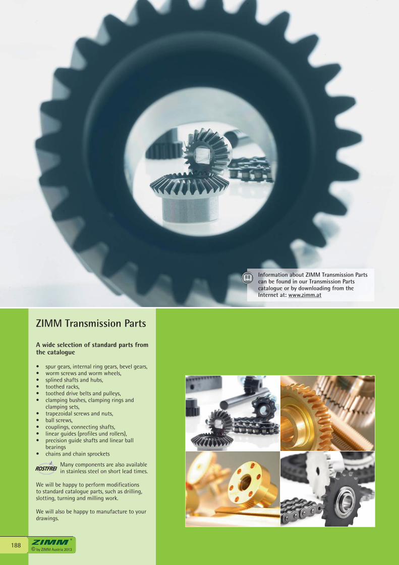
ZIMM Transmission Parts
A wide selection of standard parts fromthe catalogue
• spur gears, internal ring gears, bevel gears, • worm screws and worm wheels,• splined shafts and hubs,• toothed racks,• toothed drive belts and pulleys,• clamping bushes, clamping rings and
clamping sets,• trapezoidal screws and nuts,• ball screws,• couplings, connecting shafts,• linear guides (profiles und rollers),• precision guide shafts and linear ball
bearings• chains and chain sprockets
Many components are also availablein stainless steel on short lead times.
We will be happy to perform modificationsto standard catalogue parts, such as drilling,slotting, turning and milling work.
We will also be happy to manufacture to yourdrawings.
© by ZIMM Austria 2013188
Information about ZIMM Transmission Partscan be found in our Transmission Partscatalogue or by downloading from theInternet at: www.zimm.at

solar
189© by ZIMM Austria 2013
ZIMM Actuators ZSA
Precisely following the sun - withtracking drives
The field of activity of our sister companyZIMM Solar GmbH is very large solar powerarrays, such as those installed in Spain,Germany and the USA. So as to achieve hehighest possible power generation, thephotovoltaic cells track the sun at exactly theright angle from sunrise to sunset, using ZIMMPower Jack Systems “actuators”. Preciselytracking the sun!
As well as photovoltaic installations, ZIMMactuators are also used for satellite tracking,wind turbines, cladding and shading systems,door drives and other industrial applications.
• Sturdy design accepts high tensile andcompressive forces (available in 3 sizes)
• Quick and easy connection• Resistant to wind and weather• Low-maintenance for 20 years and more• Alignment precision to 0.1 mm• High reliability• Flexible power supply arrangement (24 V DC, 230 V AC, 230/400 V AC, etc.)• Integral rotary pulse encoders and
limit switches• Control options include CAN bus
Phot
os: A
LTEC
and
And
aSun
ZIMM Actuators ZSA can be found in ourActuators catalogue or by downloadingfrom the Internet at: www.zimm-solar.com
10
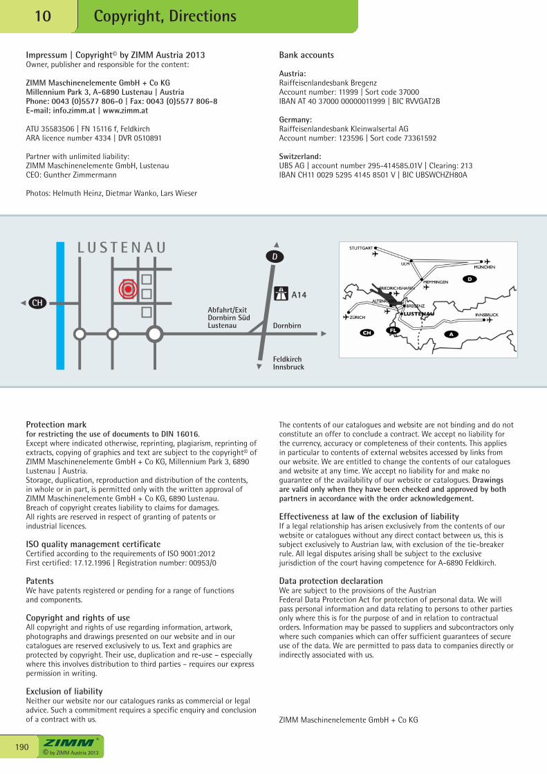
Dornbirn
FeldkirchInnsbruck
Abfahrt/ExitDornbirn SüdLustenau
L U S T E N A U
A14CH
D
© by ZIMM Austria 2013190
Copyright, Directions10
Bank accounts
Austria:Raiffeisenlandesbank BregenzAccount number: 11999 | Sort code 37000IBAN AT 40 37000 00000011999 | BIC RVVGAT2B
Germany:Raiffeisenlandesbank Kleinwalsertal AGAccount number: 123596 | Sort code 73361592
Switzerland:UBS AG | account number 295-414585.01V | Clearing: 213IBAN CH11 0029 5295 4145 8501 V | BIC UBSWCHZH80A
Impressum | Copyright© by ZIMM Austria 2013Owner, publisher and responsible for the content:
ZIMM Maschinenelemente GmbH + Co KGMillennium Park 3, A-6890 Lustenau | AustriaPhone: 0043 (0)5577 806-0 | Fax: 0043 (0)5577 806-8E-mail: info.zimm.at | www.zimm.at
ATU 35583506 | FN 15116 f, FeldkirchARA licence number 4334 | DVR 0510891
Partner with unlimited liability:ZIMM Maschinenelemente GmbH, LustenauCEO: Gunther Zimmermann
Photos: Helmuth Heinz, Dietmar Wanko, Lars Wieser
Protection markfor restricting the use of documents to DIN 16016.Except where indicated otherwise, reprinting, plagiarism, reprinting ofextracts, copying of graphics and text are subject to the copyright© ofZIMM Maschinenelemente GmbH + Co KG, Millennium Park 3, 6890Lustenau | Austria.Storage, duplication, reproduction and distribution of the contents,in whole or in part, is permitted only with the written approval ofZIMM Maschinenelemente GmbH + Co KG, 6890 Lustenau. Breach of copyright creates liability to claims for damages.All rights are reserved in respect of granting of patents orindustrial licences.
ISO quality management certificateCertified according to the requirements of ISO 9001:2012First certified: 17.12.1996 | Registration number: 00953/0
PatentsWe have patents registered or pending for a range of functionsand components.
Copyright and rights of useAll copyright and rights of use regarding information, artwork,photographs and drawings presented on our website and in ourcatalogues are reserved exclusively to us. Text and graphics areprotected by copyright. Their use, duplication and re-use – especiallywhere this involves distribution to third parties – requires our expresspermission in writing.
Exclusion of liabilityNeither our website nor our catalogues ranks as commercial or legaladvice. Such a commitment requires a specific enquiry and conclusionof a contract with us.
The contents of our catalogues and website are not binding and do notconstitute an offer to conclude a contract. We accept no liability forthe currency, accuracy or completeness of their contents. This appliesin particular to contents of external websites accessed by links fromour website. We are entitled to change the contents of our cataloguesand website at any time. We accept no liability for and make noguarantee of the availability of our website or catalogues. Drawingsare valid only when they have been checked and approved by bothpartners in accordance with the order acknowledgement.
Effectiveness at law of the exclusion of liabilityIf a legal relationship has arisen exclusively from the contents of ourwebsite or catalogues without any direct contact between us, this issubject exclusively to Austrian law, with exclusion of the tie-breakerrule. All legal disputes arising shall be subject to the exclusivejurisdiction of the court having competence for A-6890 Feldkirch.
Data protection declarationWe are subject to the provisions of the AustrianFederal Data Protection Act for protection of personal data. We willpass personal information and data relating to persons to other partiesonly where this is for the purpose of and in relation to contractualorders. Information may be passed to suppliers and subcontractors onlywhere such companies which can offer sufficient guarantees of secureuse of the data. We are permitted to pass data to companies directly orindirectly associated with us.
ZIMM Maschinenelemente GmbH + Co KG
191© by ZIMM Austria 2013
General Terms and Conditions10
General Terms and Conditions
ZIMM Maschinenelemente GmbH + Co KG, Millennium Park 3, 6890 Lustenau/AustriaPhone: 0043(0)5577/806-0, Fax: 0043(0)5577/806-8, E-mail: [email protected], www.zimm.at
These on-site trial runs are necessary to achieve system alignmentand to eliminate any factors which may impair operation. We donot accept any liability for damage that is traceable back to thenon-performance of on-site trials under load and representativeworking conditions. Furthermore we do not accept any liability,except where we have entered into a written assurance to thecontrary, for installation of our products in any type of landvehicle, aircraft or water craft
5.3. Our contractual partners are obligated to verify goods afterdelivery and, if necessary, inform us in writing immediately, and inany case no later than within 14 days after delivery, about anydefects. If no notice of defects is communicated within this timelimit, the goods that are delivered are deemed approved andwarranty claims –and damage claims shall be excluded.
5.4. Our liability shall be limited to intentional and severe grossnegligence. Any liability for ordinary negligence, for consequentialdamages, financial loss, loss of profit, loss of interest or fordamages resulting from claims of third parties shall be excluded.
5.5. Mechatronic productsEspecially for applications that are installed outdoors,the equipment is subject to environmental conditions to anincreased degree. If malfunctions arise, we require documentaryevidence of the cause, such as environmental influences orproduct defects.
5.6. Rectification of defectsIf product defects are accepted, the defective parts must bereturned to us without delay, together with documentation of thedefect. Your analysis of the cause of the defect is the basis for ourlaboratory testing and sustained defect prevention measures.The transport costs will be borne y the sender in each case.
6. Retention of title6.1. All goods delivered shall remain our sole property until complete
payment of the purchase price.6.2. Our contractual partner is obliged to treat the goods carefully as
long as retention of title applies to the delivered goods.If maintenance and/or inspection work is necessary, ourcontractual partner shall carry out such work regularly at hisown expense.
6.3. Installation or modification of the delivered contractual goods willnot result in loss of title to those goods.Our contractual partner is not entitled to resell the deliveredcontractual goods as long as retention of title remains in force.
7. Place of performance | Applicable law | Place of jurisdictionThe exclusive place of performance for all contractual relations isA-6890 Lustenau. Austrian law applies exclusively, with exclusionof the tie-breaker rule.All legal disputes arising from or relating to the business relationsand contracts shall be subject to the exclusive jurisdiction of thecourt having competence for A-6800 Feldkirch.
8. Severability clauseShould any individual provisions in the above general terms andconditions be or become invalid, either in part or in full, this willnot affect the validity of the other provisions.The invalid provision will be replaced by a ruling that is as close aspossible in economic purpose to the invalid provision in a legallyeffective and practicable form.
ZIMM Maschinenelemente GmbH + Co KG
1. General:All our contracts are subject to the following terms and conditionsunless agreed to the contrary in writing: These terms andconditions are deemed acknowledged and agreed by signing thecontract. Any terms and conditions – of any nature – contrary toour general terms and conditions shall be completely inapplicableand invalid, irrespective of the form in which they were broughtto our knowledge. Deviations from these general terms andconditions shall be effective only if they have been agreed andconfirmed by us in writing. Any agreement to abandon this formalrequirement must equally be in writing and signed by bothparties. Silence concerning any terms and conditions that deviatefrom our standard conditions shall not be regarded as consent.
2. Quotations | prices | contractual content2.1. Our quotations remain valid for 60 days after submission,
subject to changes in accordance with Point 2.5.2.2. Information in our our catalogues is not contractually binding
(see also Point 3).2.3. All our prices are understood to be in Euros and exclusive of VAT.
Unless agreed to the contrary, the prices to be invoiced will be ourlist prices at the time of concluding the contract. These prices areex works, excluding packaging, freight and/or shipping.Where consignment and delivery have been contractually agreed,prices do not include costs for unloading and transportation tothe working site. Risk and rights of use are transferred to ourcontractual partner at the time of shipment. Delivery is thusalways ex works.
2.4. Delivery lead times and dates are binding provided they havebeen promised by us in writing. This commitment lapses if ourcontractual partner requests modification of the order afterplacing the order or if obstacles outside our control occur,due for instance to force majeure or late delivery by our suppliers.
2.5. Changes to economic circumstancesIf new circumstances arise outside our control, such as materials,taxes, wage rates, strike, war, terrorist attacks, blockades, fire,natural catastrophes or acts of God, we are entitled to amend ourquotations and contracts accordingly. This applies particularly inthe event that the prices of copper or aluminium rise by morethan 10%. In all these cases we are entitled, even after concludingthe contract, to amend our prices and due dates.
3. Design and specificationSelection and dimensioning is the customer’s responsibility,because we are not familiar with the design criteria such asinstallation location and type of application. On request we canprovide support during selection and specification and makeproposals with subassembly drawings and calculations based onyour application parameters. This drawing including the parts listis subject to checking by you and approval by us. The drawingchecked and approved by you is the basis for productionand assembly.
4. Technical modifications during the contractWe are entitled to implement technical modifications after theconclusion of the contract, provided such modifications do notaffect the contractual guaranteed performance of the goods.
5. Warranty and liability for defects5.1. The warranty period is 1 year, without exception. Changes to the
warranty period require our express commitment in writing.5.2. Trial runs without load and under load in normal operating conditions
(according to your design parameters) are necessary to ensure reliableoperation. We perform our trials under no-load conditions, not underload, but under the customer’s installation conditions.
10

© by ZIMM Austria 2013192
Distributors in your area10
Ing. R. Longhi GmbH + CoRingstrasse 16923 LauterachPhone 0043 (0) 5574 / 799 83Fax 0043 (0) 5574 / 799 [email protected]
Gerhard BellBillrothstrasse 324050 TraunPhone 0043 (0) 664 / 422 79 12Fax 0043 (0) 7229 / 755 [email protected]
Reinhardt MayerTurmgasse 3a8700 LeobenPhone 0043 (0) 664 / 183 66 00Fax 0043 (0) 3842 / 479 [email protected]
Austria – your local ZIMM representative
Achenbach AntriebstechnikAm Stubben 721244 Buchholz i.d.N.Phone 0049 (0) 4181 / 38 03 75Fax 0049 (0) 4181 / 38 03 76Mobile 0049 (0) 171 / 245 86 71info@achenbachantriebstechnik.dewww.achenbachantriebstechnik.de
Ing.-Büro RisseKetscher Strasse 5a08141 Reinsdorf/ OT VielauPhone 0049 (0) 375 / 60 67 04-0Fax 0049 (0) 375 / 60 67 04-1Mobile 0049 (0) 171 / 703 19 [email protected]
Hagener Fördertechnik GmbHKoksstrasse 1058135 HagenPhone 0049 (0) 2331 / 94 80-0Fax 0049 (0) 2331 / 94 80-99Mobile 0049 (0) 171 / 770 18 [email protected]
KW Antriebs- & Automationstechnik GmbHKoberger Strasse 3990408 NurembergPhone 0049 (0) 911 / 366 33 69-0Fax 0049 (0) 911 / 366 33 [email protected]
Prantner IndustrieVertretungBraikinbachweg 472766 ReutlingenPhone 0049 (0) 7121 / 748 010Fax 0049 (0) 7121 / 748 [email protected]
Bretzel GmbHAntriebs- und ElektrotechnikIndustriestraße 965760 EschbornPhone 0049 (0) 6196 / 403 19-0Fax 0049 (0) 6196 / 430 [email protected]
Germany – your local ZIMM representative
Alfred Imhof AGJurastrasse 104142 MünchensteinPhone 0041 (0) 61 / 417 17 17Fax 0041 (0) 61 / 417 17 [email protected]
Switzerland – your local ZIMM representative
You can find current addresses at www.zimm.at
Alter Rhein, Lustenau

T.E.A. Transmissions Pty Ltd.Tahiti RoadTiaro, QLD 4650Phone 0061 (0) 7 / 412 925 33Fax 0061 (0) 7 / 412 924 [email protected]
SaecoWilson Ltd.88 Hastie Ave, Mangere1122 AucklandPhone 0064 (0) 9 / 634 75 40Fax 0064 (0) 9 / 634 75 [email protected]
JUNGWOO F&B Corp.118, Nae-dong, Ojeong-gu,Bucheon-City, Gyeonggi-DoRepublic of Korea, 421-805Phone 0082 (0) 32 / 683 62 00Fax 0082 (0) 32 / 684 10 [email protected]
GTA - German Tech Auto Co., Ltd.No.162, Hsin sheng RoadTaishan HsiangTaipei County 243Taiwan R.O.CPhone 00886 (0) 2 / 290 309 39Fax 00886 (0) 2 / 290 306 [email protected]
DPT - Dynamic PowerTransmission Co., Ltd.Block 5, No 1699, Songze RoadXujing Industrial Zone, ShanghaiP.R. ChinaPost Code: 201702Phone 0086 (0) 21 / 598 839 78Fax 0086 (0) 21 / 598 839 [email protected]
Chemlani Technology31 Haifa Road28226 Kiryat AtaPhone 0972 4 / 841 53 95Fax 0972 4 / 841 53 [email protected]
Servotechnica ZAO22, Vyborgskaya str.125130 MoscowPhone 007 (0) 495 / 797 88 66Fax 007 (0) 495 / 450 00 [email protected]
Stankoservice-Sokol OOOul. Tschasowaya 28 Building 4125315 MoscowPhone 007 (0) 495 / 225 13 39Fax 007 (0) 495 / 225 13 [email protected]
SEW-EURODRIVE n.v./s.a.Research Park HassrodeEvenementenlaan 73001 LeuvenPhone 0032 (0) 16 / 386 311Fax 0032 (0) 16 / 386 [email protected]
BETZ s.r.o.Trída Vítezství 68/435301 Mariánské LáznePhone 0042 (0) 354 / 620 095Fax 0042 (0) 354 / 627 [email protected]
ZF Danmark ApSTaastrupgaardsvej 8-102630 TaastrupPhone 0045 (0) 43 / 436 243Fax 0045 (0) 43 / 432 [email protected]
EIE Maskin OyPL 80, Asematie 110601 TammisaariPhone 00358 (0) 19 / 223 91 00Fax 00358 (0) 19 / 223 91 [email protected]
AGORA Technique S.a.r.l.8 Bis Rue VoltaParc Volta94140 AlfortvillePhone 0033 (0) 1 / 451 843 70Fax 0033 (0) 1 / 451 843 [email protected]
HepcoMotionLower Moor Business ParkTiverton Way, TivertonDevon, EX16 6TG,Phone 0044 (0) 1884 / 257 000Fax 0044 (0) 1884 / 243 [email protected]
IRAMKO Drive Ltd.Weiss Manfréd út 4.1211 BudapestPhone 0036 (0) 1 / 425 73 54Fax 0036 (0) 1 / 425 73 [email protected]
ECKERLE Industrie Kft.Dózsa György út 446200 KiskörösPhone 0036 (0) 78 / 511 400Fax 0036 (0) 78 / 511 [email protected]
TECNOPOWER S.L.Poligono Industrial Moli dels FraresCalle C n° 1008620 Sant Vicenc Dels HortsBarcelonaPhone 0034 (0) 93 / 656 80 50Fax 0034 (0) 93 / 656 80 [email protected]
EIE Maskin ABBox 712124 BandhagenPhone 0046 (0) 8 / 727 88 00Fax 0046 (0) 8 / 727 88 [email protected]
STAR HIDROPARMak. Parcalari San. LTD. STI.B Block, No: 1611Perpa Is Merkezi Kat 1134384 Okmeydani-ISTANBULPhone 0090 (0) 212 / 222 40 84Fax 0090 (0) 212 / 221 09 [email protected]
FAVARI TRANSMISSIONI SRLVia Stephenson 9220157 MilanPhone 0039 02 / 357 04 41Fax 0039 02 / 332 007 [email protected]
Groneman BVAmarilstraat 11, Postbus 247550 AA Hengelo (O)Phone 0031 (0) 74 / 255 11 40Fax 0031 (0) 74 / 255 11 [email protected]
EIE Maskin ASTvetenveien 1640671 OsloPhone 0047 (0) 67 / 572 270Fax 0047 (0) 67 / 572 [email protected]
INMET-BTHUl. Jasna 1-543-190 MikolówPhone 0048 (0) 32 / 726 19 11Phone 0048 (0) 32 / 738 19 48Fax 0048 (0) 32 / 726 18 [email protected]
JORDAN matcon Sp. z o.o.Kijewo 5063-000 Sroda WielkopolskaPhone 0048 (0) 61 / 286 07 01Fax 0048 (0) 61 / 286 07 [email protected]
EQUINOTEC S.A.Av. Villagarcia de Arosa 11204450-300 MatosinhosPhone 00351 (0) 22 / 935 07 55Fax 00351 (0) 22 / 935 10 [email protected]
Patrascu & Gane EngineeringCompany S.R.LStr. Vasile Gherghel, Nr. 18CSector 1011523 BucharestPhone 0040 (0) 21 / 222 95 40Fax 0040 (0) 21 / 222 95 [email protected]
LESNIK LENART, d.o.o.Zgornjl Zerjavci 33a2230 LenartPhone 00386 (0) 2 / 729 24 03Fax 00386 (0) 2 / 729 24 [email protected]
NORTH andSOUTH AMERICA
DIEQUA Corporation180 Covington DriveBloomingdale, Illinois 60108-3105Phone 001 (0) 630 / 980 11 33Fax 001 (0) 630 / 980 12 [email protected]
LF Catelani EquipamentosRua Abilio Figueiredo, n92 - sl85Jundiai - Sao Paulo - BrazilZipcode: 13208-140Phone 0055 (0) 11 / 4497-1735Fax 0055 (0) 11 / [email protected]
International Distributors10
EUROPE
ASIA
AUSTRALIA andNEW ZEALAND
10
BELGIUM
CZECH REPUBLIC
SLOVAKIA
ITALY
NETHERLANDS
NORWAY
SPAIN
SWEDEN
SOUTH KOREA
TAIWAN
AUSTRALIA
NEW ZEALAND
TURKEY
CHINA
ISRAEL
RUSSIA
POLAND
PORTUGAL
ROMANIA
SLOVENIA
DENMARK
FINLAND
FRANCE
GREAT BRITAIN
HUNGARY
USA
CANADA
BRAZIL

ZIMM Maschinenelemente GmbH + Co KGMillennium Park 36890 Lustenau/AustriaPhone: 0043(0)5577/806-0Fax: 0043(0)5577/806-8E-mail: [email protected]: www.zimm.at
Vers
ion
05/2
013