Revista Competitividad: Tendencias en SCM y logística (YOBEL SCM)

208
JIS symbol
Round shaped medium bore size cylinder, double acting/single rod type
SCM Series• Bore size: 20, 25, 32, 40 mm
50, 63, 80, 100 mm
CAD DATA AVAILABLE.
1000
1500
Stroke lengthStandard stroke length (mm) Max. stroke length (mm) Min. stroke length (mm)Bore size (mm)
25, 50, 75, 100,
125, 150, 200,
250, 300
20 dia.
25 dia.
32 dia.
40 dia.
50 dia.
63 dia.
80 dia.
100 dia.
10: Without switch
10: One switch (Note)
25: Two switches
40: 3 switches (proximity switch)
50: 3 switches (reed switch)
55: 4 switches
75: 5 switches (proximity switch)
85: 5 switches (reed switch)
32 dia.
8.6
0.5
2.5
40 dia.
8.6
0.9
3.7
50 dia.
13.4
1.6
8.0
63 dia.
(to 1000),
(to 1000),
13.4
1.6
14.4
80 dia.
Rc3/8
Rc3/8
15.4
3.3
25.4
Specifications
Bore size mm
Actuation
Working fluid
Max. working pressure MPa
Min. working pressure MPa
Withstanding pressure MPa
Ambient temperature °CPort size
Working piston speed mm/s
Cushion
Effective air cushion length mm
Lubrication
M5
+1.4
0
+1.4
0
0.1
Rc1/8
(to 1000)
(to 1000)
Rc1/8
SCM
Rc1/4
Rc1/4
0.05
Rubber cushioned
Air cushioned
Rubber
cushioned
Air
cushioned
Double acting
Compressed air
1.0
1.6
-10 to 60 (to be unfrozen)
30 to 1000 (use it within the range of allowable energy absorption.)
Rubber cushion/air cushion can be selected.
Not required (when lubrication, use turbine oil ISO VG32.)
Descriptions
20 dia.
8.1
0.1
0.8
25 dia.
8.1
0.2
1.2
100 dia.
Rc1/2
Rc1/2
(to 1500)
(to 1500)
15.4
5.8
45.6
+1.4
0(to 1500)
+1.4
0(to 1500)
Rubber cushioned
Air cushioned
Note: When one switch is installed and 10 to 25 mm stroke, switch rail installation position is different. Please refer to Page 283 about the installation position.Also, manufacturing of mounting style trunnion type is not available.
Allowable energy absorption J
Stroketolerance
mm
+2.3
0
+1.4
0
+2.7
0
+1.8
0
209
Standard type
Ro
un
d sh
aped
cylind
er
SCP * 2
CMK2
CMA2
SCM
SCA2
SCS
CKV2
CAT
MDC2
MVC
SMD2
SSD
FC *
JSB3
UCAC
LCS
LCY
STR2
UCA2
STK
USSD
USC
MFC
GLC
SHC
CAC3
HCM
HCA
MRL2
SRL2
SRG
SRM
SRT
SRB2
CAV2/COV * 2
MSD/MSDG
ULKP/ULKJSK2/JSM2
STS/STL
SSD (large)
JSC3 (medium)JSC3 (large)
SCM Series
Specifications
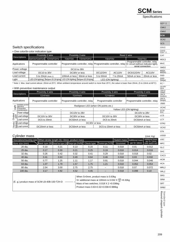
Cylinder mass
Switch specifications• One color/bi-color indication type
Basic type (00)
Descriptions/mounting style
Bore size (mm)
DescriptionsProximity 2 wire
T2H/T2V/T2JH/T2JV T2YH/T2YV
LED (ON lighting) Red/green LED (ON lighting)
T3H/T3V T3YH/T3YV
100mA or less 50mA or less
T0H/T0V T5H/T5V
Proximity 3 wire Reed 2 wire
Applications
Power voltage
Load voltage
Load current
Light
Programmable controller
–
DC10 to 30V
5 to 20mA (Note 1)
LED (ON lighting) Red/green LED (ON lighting)
Programmable controller, relay
DC10 to 28V
DC30V or less DC12/24V
5 to 50mA
Red/green LED (when ON points etc.)
DC30V or less
AC110V
7 to 20mA
DC5/12/24V
50mA or less
AC110V
20mA or less
Programmable controller, relay
LED (ON lighting) –
When stroke length (S) =0mm, product mass Switch mass
20 dia.
25 dia.
32 dia.
40 dia.
50 dia.
63 dia.
80 dia.
100 dia.
0.10
0.17
0.26
0.41
0.77
1.07
2.04
3.17
Axial foot type (LB)0.21
0.30
0.42
0.63
1.25
1.79
3.00
4.92
Flange type (FA/FB)
0.13
0.21
0.32
0.49
1.11
1.57
2.75
4.52
Clevis type
0.15
0.25
0.41
0.64
1.17
1.75
2.75
4.45
Trunnion type (TA/TB)
0.11
0.19
0.29
0.46
0.91
1.21
–
–
Grommet
0.018
0.018
0.018
0.018
0.018
0.018
0.018
0.018
Additional mass per S= 10mm
0.01
0.014
0.018
0.03
0.044
0.052
0.07
0.098
0.012
0.016
0.02
0.032
0.046
0.054
0.072
0.10
Additional mass per S= 10mm
(with switch rail)
(Unit: Kg)
(E. g.) product mass of SCM-LB-40B-100-T2H-D
When S=0mm, product mass is 0.63kg
S= additional mass at 100mm is 0.032 X 100 =0.32kg
Mass of two switches, 0.018 X 2 =0.036kg
Product mass 0.63+0.32+0.036=0.986kg
10
–
– Yellow LED (ON lighting)
• With preventive maintenance output
DescriptionsProximity 3 wire
T2YFH/V
Proximity 4 wire
T3YFH/V
Proximity 3 wire
T2YMH/V
Proximity 4 wire
T3YMH/V
Applications
Power voltage
Load voltage
Load current
Load voltage
Load current
Programmable controller
–
DC10V to 30V
DC5 to 20mA
DC20mA or less
Programmable controller, relay
DC10V to 28V
DC30V or less
DC50mA or less
DC50mA or less
Programmable controller
–
DC10V to 30V
DC5 to 20mA
DC5 to 20mA or less
Programmable controller, relay
DC10V to 28V
DC30V or less
DC50mA or less
DC50mA or less
Ligh
tO
utpu
t pa
rtPre
ventive
ma
intenan
ce
* Note 1: Max. load current above: 20mA at 25°C. When ambient temperature around switch is more than 25°C, the value is lower than 20mA. (5 to 10mA at 60°C)
Programmable controller, relay IC circuit (without indicator light),
serial connection
Installation position adjustmentPreventive maintenance

210
SCM Series
A
B
How to order
Without switch
With switch
Mounting style
Bore size
C Cushion
D Stroke length
E Switch model No.Note 2
F Switch quantityNote 3
SCM T2H100 JDB I40LB
SCM 100 JB I40LB
G OptionNote 4
H Accessory
<Example of model number>SCM-LB-40B-100-T2H-D-JIModel: Round shaped cylinder, double acting
Mounting style : Axial foot type
Bore size : 40mm
Cushion : Both sides air cushioned
Stroke length : 100mm
Switch model No : Proximity T2H switch, lead wire 1m
Switch quantity : Two
Option : Bellows material/max. ambient temperature 60°CAccessory : Rod eye
Cautions for model No. selectionNote 1: Mounting bracket is attached to the product when
shipping.Note 2: Available other than "E" Switch model No.
(custom order)Please refer to Ending 1 about details.
Note 3: Refer to the following page about how to order switch.Note 4: Instantaneous maximum temperature is the temperature
when spark and spatter etc. instantaneously contact to bellows.
Note 5: Please refer to Ending 81 about custom specifications of rod end form.
A
B
C
D
E
F
G
H
Symbol Descriptions
00LBFAFBCACBTATB
20253240506380100
BRHD
Blank35
RHDT4
JKLQMP6
IYB1B2
Bore sizeBasic typeAxial foot typeRod side flange typeHead side flange typeEye bracket typeClevis bracket typeRod side trunnion typeHead side trunnion type
20 dia.25 dia.32 dia.40 dia.50 dia.63 dia.80 dia.100 dia.
Both sides air cushionedRod side air cushionedHead side air cushionedBoth sides rubber cushioned
1m (standard)3m (option)5m (option)
One on rod sideOne on head sideTwoThree4 switches (When more than 4 switches, indicate switch quantity.)
BellowsBellowsBellowsSwitch rail attached at deliveryPiston rod material (stainless steel)Copper and PTFE free
Bore sizeRod eyeRod clevisEye bracketClevis bracket
Mounting styleA
Bore size (mm)B
CushionC
Stroke length (mm)D
E
Switch quantityF
OptionG
AccessoryH
Pro
xim
ity1 color indicator
1 color indicator
2 color indicator
With preventive maintenance output
Off delay type
2 wire
2 wire3 wire2 wire3 wire3 wire4 wire3 wire4 wire2 wire
Ree
d
25, 50, 75, 100, 125, 150, 200, 250, 300
Axial lead wire
T0H *T5H *T2H *T3H *
T2YH *T3YH *
T2YFH *T3YFH *T2YMH *T3YMH *T2JH *
Radial lead wire
T0V *T5V *T2V *T3V *
T2YV *T3YV *
T2YFV *T3YFV *T2YMV *T3YMV *T2JV *
Display Lead wire
Switch model No.
* Lead wire length
Cont
act
E
60 °C100 °C250 °C
100 °C200 °C400 °C
20 25 32 40 50 63 80 100
20 25 32 40 50 63 80 100
Max. ambient Instant max.

211
Standard type
Ro
un
d sh
aped
cylind
er
SCP * 2
CMK2
CMA2
SCM
SCA2
SCS
CKV2
CAT
MDC2
MVC
SMD2
SSD
FC *
JSB3
UCAC
LCS
LCY
STR2
UCA2
STK
USSD
USC
MFC
GLC
SHC
CAC3
HCM
HCA
MRL2
SRL2
SRG
SRM
SRT
SRB2
CAV2/COV * 2
MSD/MSDG
ULKP/ULKJSK2/JSM2
STS/STL
SSD (large)
JSC3 (medium)JSC3 (large)
SCM Series
How to order
How to order mounting bracket
20 dia.Bore size (mm)
Mounting bracketFoot (LB)
Flange (FA/FB)
Eye (CA)
Clevis (CB)
Trunnion (TA/TB)
SCM-LB-20
SCM-FA-20
SCM-CA-20
–
SCM-TA-20
25 dia.
SCM-LB-25
SCM-FA-25
SCM-CA-25
–
SCM-TA-25
32 dia.
SCM-LB-32
SCM-FA-32
SCM-CA-32
–
SCM-TA-32
40 dia.
SCM-LB-40
SCM-FA-40
SCM-CA-40
–
SCM-TA-40
50 dia.
SCM-LB-50
SCM-FA-50
SCM-CA-50
–
SCM-TA-50
63 dia.
SCM-LB-63
SCM-FA-63
SCM-CA-63
–
SCM-TA-63
80 dia.
SCM-LB-80
SCM-FA-80
–
SCM-CB-80
–
SCM-LB-100
SCM-FA-100
–
SCM-CB-100
–
100 dia.
Switch model No.
Switch model No.
How to order switch• Switch main body + mounting rail set
SCM T0H * D 40FE
Bore size
B
B
Switch quantity
D
D
Stroke length (Note 1)
• Switch only
T0H *SWE
100
• Mounting rail only
SCM T 40
Bore size
B
Mounting rail
D
Stroke length
100
• Note: Mounting bolts are attached to each mounting bracket.
E Switch model No.
Axial lead wire
T0H *
T5H *
T2H *
T3H *
T2YH *
T3YH *
T2YFH *
T3YFH *
T2YMH *
T3YMH *
Radial lead wire
T0V *
T5V *
T2V *
T3V *
T2YV *
T3YV *
T2YFV *
T3YFV *
T2YMV *
T3YMV *
Ree
dP
roxi
mity
2 wire
3 wire
2 wire
3 wire
3 wire
4 wire
3 wire
4 wire* mark shows lead wire length.
Bore size Stroke length (mm)
20
25
32
40
50
63
80
100
20 dia.
25 dia.
32 dia.
40 dia.
50 dia.
63 dia.
80 dia.
100 dia.
Standard stroke length
25
50
75
100
125
150
200
250
300
X
F Switch quantity
R
D
T
4
5
One
Two
Three
4 pcs.
5 pcs.When more than 4 switches, indicate switch quantity.
Note 1: When more than 300mm stroke, indicate "X".When more than 300 mm stroke, a short rail (100 mm switch adjustment distance) is provided per switch.
Note 2: When placing an order of mounting rail only, this is indicated by "X", order rails as same quantity as using switches.
* Lead wire length
Blank
3
5
1m
3m
5m
(Note 1)(Note 2)

214
• Basic type (00) 20 to 100 mm bore<Rubber cushioned>
Note 1: Please refer to Page 283 about HD, RD dimensions of 2 color indicator type preventive maintenance output switch.Note 2: Please refer to Page 283 about dimensions of projecting section of 2 color indicator type preventive maintenance output switch.
<Air cushioned>For 20, 25 mm bore cylinder, piping ports are different.
(File name: Page 286 or Ending 114)
Dimensions
20 dia.
25 dia.
32 dia.
40 dia.
50 dia.
63 dia.
80 dia.
100 dia.
Symbol
Bore size (mm)
18
22
22
30
35
35
40
40
15.5
19.5
19.5
27
32
32
37
37
26
31
38
47
58
72
89
110
A
13
17
17
22
27
27
32
41
B C
24
29
36
44
55
69
80
100
MC
M5
M6
M8
M10
M12
M14
–
–
MD
8
10
12
16
20
20
25
30
MM
6
8
10
14
18
18
22
26
MN
M4 depth 6.5
M5 depth 6.5
M5 depth 7.5
M6 depth 12
M8 depth 16
M10 depth 16
M10 depth 22
M12 depth 22
DA
Rc1/8
Rc1/8
Rc1/8
Rc1/8
Rc1/4
Rc1/4
Rc3/8
Rc1/2
EE (Note)
12
14
18
25
30
32
40
50
J
4
5
5.5
6
7
7
11
11
MO
2
2
2
2
2
2
3
3
N
12
12
12
13
15
15
15
15
QA
10
10
10
12
12
12
15
15
QB
14
16.5
20
26
32
38
50
60
SD
5
6
6
8
11
11
13
16
T
M8
M10 X 1.25
M10 X 1.25
M14 X 1.5
M18 X 1.5
M18 X 1.5
M22 X 1.5
M26 X 1.5
KK
69
69
71
78
90
90
108
108
LL
11
11
11
12
13
13
–
–
MAD
11
11
10
10
12
12
–
–
MB
17
18
18
20
23
23
31
31
106
111
113
130
150
150
182
182
35
40
40
50
58
58
71
71
WF X
30°30°25°20°20°20°20°20°
17
17
17
19
22
22
28
28
GH
19
19
19
20
25
25
28
28
GR
19.5
22
25.5
30
35.5
42.5
51
61.5
P
30
35
31.5
40
46
46
55
56
b
30
30
35
35
40
40
50
60
d
25.7
30.7
37.7
46.7
57.7
71.7
88.7
109.7
s
(Stroke length/3) + 18.5
(Stroke length/3) + 20.5
(Stroke length/3) + 19
(Stroke length/3) + 18.5
(Stroke length/3.6) + 18.5
(Stroke length/3.6) + 18.5
(Stroke length/4.3) + 14.5
(Stroke length/4.5) + 21
EA
14
14
14
15
18.5
18.5
20
20
18
18
18
18
18
18
18
18
GA
23
24.4
25
25.7
26.2
26.5
26.7
26.7
GB
3.8
2.8
3.8
5.8
8.3
8.3
10.4
10.4
T0, T5HD RD
6.8
5.8
6.8
8.8
11.3
11.3
13.4
13.4
T2, T3
6.7
7.7
8.7
10.7
12.2
12.2
19.1
19.1
T0, T5
7.7
8.7
9.7
11.7
13.2
13.2
20.1
20.1
T2, T3
12
12
12
13
15.5
15.5
20
20
EB
27
29.5
32.8
36.6
43
50
58.5
69
ECXF
M5
M5
Rc1/8
Rc1/8
Rc1/4
Rc1/4
Rc3/8
Rc1/2
EE*
Basic type (00) basic dimensions
20 dia.
25 dia.
32 dia.
40 dia.
50 dia.
63 dia.
80 dia.
100 dia.
Symbol
Bore size (mm)
With switchBellows Air cushioned
E
Bellows 20, 25 mm bore, piston rod section
MM
dia
.
d di
a.
s di
a.
A
EC(M
ax)
C
2
KK
E10°
MO
WF
EA
Air cushion needle
EB 2-EE*A
b
MM
dia
.
A
C
2
KK
MO
WF EA
Air cushion needle
EB M5 X 0.8
X + + stroke length
XF +
WF +
Width across flats B
Width across flats B
SCM Series
MM
dia
.
MM
dia
.
J di
a.
J di
a.
D d
ia.
d di
a.
s di
a.
MO
MN (width across flats)
SD±0.1
SD
±0.1
8-DA
Bellows 20, 25 mm bore, piston rod section
MC
GB
GA
A
CC N GR GH
QBQAT
RD HD
2-EE
2KK KK XF MA MB4-MDMO
WFA NWF
A
b
X + stroke length
LL + stroke length
P
Width across flats B
X + + stroke length
WF +
XF +

215
Standard type
Ro
un
d sh
aped
cylind
er
SCP * 2
CMK2
CMA2
SCM
SCA2
SCS
CKV2
CAT
MDC2
MVC
SMD2
SSD
FC *
JSB3
UCAC
LCS
LCY
STR2
UCA2
STK
USSD
USC
MFC
GLC
SHC
CAC3
HCM
HCA
MRL2
SRL2
SRG
SRM
SRT
SRB2
CAV2/COV * 2
MSD/MSDG
ULKP/ULKJSK2/JSM2
STS/STL
SSD (large)
JSC3 (medium)JSC3 (large)
• Axial foot type (LB) (File name: Page 286 or Ending 114)
Note 1: Needle relevant dimensions and port size of air cushioned types are as same as basic type.Refer to Page 214. (20 and 25 mm bore cylinders are different from basic type).
Note 2: Please refer to Page 283 about HD, RD dimensions of 2 color indicator type preventive maintenance output switch.Note 3: Please refer to Page 283 about dimensions of projecting section of 2 color indicator type preventive maintenance output switch.
Dimensions
20 dia.
25 dia.
32 dia.
40 dia.
50 dia.
63 dia.
80 dia.
100 dia.
Symbol
Bore size (mm)
18
22
22
30
35
35
40
40
15.5
19.5
19.5
27
32
32
37
37
26
31
38
47
58
72
89
110
A
13
17
17
22
27
27
32
41
B C
28.9
29.9
30.9
33.4
40.5
40.5
55
55
LF
20
22
25
30
40
45
55
65
LH
69
69
71
78
90
90
108
108
LL
32
36
44
54
66
82
100
120
LR
M4
M5
M5
M6
M8
M10
M10
M12
DA
Rc1/8
Rc1/8
Rc1/8
Rc1/8
Rc1/4
Rc1/4
Rc3/8
Rc1/2
EE (Note 1)
44
49
58
71
86
106
125
150
LS
3.2
3.2
3.2
3.2
4.5
4.5
4.5
6
LT
45.2
45.2
45.2
51.2
55
55
60
60
LX
2.6
3.4
3.4
4
5
5
6
7
M
8
10
12
16
20
20
25
30
MM
12
12
12
13
15
15
15
15
QA
M8
M10 X 1.25
M10 X 1.25
M14 X 1.5
M18 X 1.5
M18 X 1.5
M22 X 1.5
M26 X 1.5
KK
7.1
7.1
8.1
9.1
11
13
14
16
LC
15.1
15.1
16.1
16.6
22
22
28.5
30
LB
109.8
115.6
117.6
135.2
157.5
157.5
189.5
192
LA
5.7
5.7
6.8
6.8
9
11
11
14
LDD
4
4
4
4
5
5
6
6
LE
10
10
10
12
12
12
15
15
14
16.5
20
26
32
38
50
60
5
6
6
8
11
11
13
16
QB SD
19
19
19
20
25
25
28
28
GR
19.5
22
25.5
30
35.5
42.5
51
61.5
P
18
18
18
18
18
18
18
18
GA
23
24.4
25
25.7
26.2
26.5
26.7
26.7
GB
10
10
10
10
17.5
17.5
20
20
W
17
18
18
20
23
23
31
31
WF
30
35
31.5
40
46
46
55
56
b
Stroke length/3) + 18.5
(Stroke length/3) + 20.5
(Stroke length/3) + 19
(Stroke length/3) + 18.5
(Stroke length/3.6) + 18.5
(Stroke length/3.6) + 18.5
(Stroke length/4.3) + 14.5
(Stroke length/4.5) + 21
d
30
30
35
35
40
40
50
60
3.8
2.8
3.8
5.8
8.3
8.3
10.4
10.4
T0, T5
6.8
5.8
6.8
8.8
11.3
11.3
13.4
13.4
T2, T3
6.7
7.7
8.7
10.7
12.2
12.2
19.1
19.1
T0, T5HD RD
7.7
8.7
9.7
11.7
13.2
13.2
20.1
20.1
T2, T3
25.7
30.7
37.7
46.7
57.7
71.7
—
—
sT
17
17
17
19
22
22
28
28
GH
Axial foot type (LB) basic dimensions
20 dia.
25 dia.
32 dia.
40 dia.
50 dia.
63 dia.
80 dia.
100 dia.
Symbol
Bore size (mm)
With switchBellows
SCM Series
Double acting/single rod typed
dia.
LT LH
4- LD dia.
s di
a.
A
b
d di
a.
A
b
MM
dia
.
D d
ia.
C GR GH
QBQAT
RD HD
2-EE
KK
A
MM
WW
LBLB
LF
LCLC
WF LL + stroke length
LA + stroke length
LX + stroke length
2- LE dia.
Position of dowel pin Position of dowel pin
SD±0.1
SD
±0.1
8-DA
LS
LR
GA
P
GB
With bellows 20 to 63 mm bore
With bellows 80, 100 mm bore
WF +
WF +
LF +
LA + + stroke length
LF +
LA + + stroke length
Width across flats B

216
• Rod side flange type (FA)
Note 1: Needle relevant dimensions and port size of air cushioned types are as same as basic type.Refer to Page 214. (20 and 25 mm bore cylinders are different from basic type).
Note 2: Please refer to Page 283 about HD, RD dimensions of 2 color indicator type preventive maintenance output switch.Note 3: Please refer to Page 283 about dimensions of projecting section of 2 color indicator type preventive maintenance output switch.
(File name: Page 286 or Ending 114)
3.8
2.8
3.8
5.8
8.3
8.3
10.4
10.4
T0, T5
6.8
5.8
6.8
8.8
11.3
11.3
13.4
13.4
T2, T3
6.7
7.7
8.7
10.7
12.2
12.2
19.1
19.1
T0, T5
HD
7.7
8.7
9.7
11.7
13.2
13.2
20.1
20.1
T2, T3
Dimensions
20 dia.
25 dia.
32 dia.
40 dia.
50 dia.
63 dia.
80 dia.
100 dia.
Symbol
Bore size (mm)
18
22
22
30
35
35
40
40
15.5
19.5
19.5
27
32
32
37
37
26
31
38
47
58
72
89
110
A
13
17
17
22
27
27
32
41
B C
M8
M10 X 1.25
M10 X 1.25
M14 X 1.5
M18 X 1.5
M18 X 1.5
M22 X 1.5
M26 X 1.5
KK
69
69
71
78
90
90
108
108
LL
24
29
36
44
55
69
80
100
MC
M4
M5
M5
M6
M8
M10
M10
M12
DA
Rc1/8
Rc1/8
Rc1/8
Rc1/8
Rc1/4
Rc1/4
Rc3/8
Rc1/2
EE (Note 1)
8
10
12
16
20
20
25
30
MM
2
2
2
2
2
2
3
3
N
12
12
12
13
15
15
15
15
QA
10
10
10
12
12
12
15
15
QB SD
14
16.5
20
26
32
38
50
60
FD
28
32
38
46
58
70
82
100
5.5
5.5
6.6
6.6
9
11
11
13
FL
77
78
80
88
101
101
122
125
FG
11
11
11
12
14
14
20
17
FF
40
44
53
61
76
92
104
128
FMD
6
7
7
8
9
9
11
14
FT
12
14
18
25
30
32
40
50
J
5
6
6
8
11
11
13
16
17
18
18
20
23
23
31
31
106
111
113
130
150
150
182
182
T WF
30
35
31.5
40
46
46
55
56
b
30
30
35
35
40
40
50
60
d
25.7
30.7
37.7
46.7
57.7
71.7
—
—
s
(Stroke length/3) + 18.5
(Stroke length/3) + 20.5
(Stroke length/3) + 19
(Stroke length/3) + 18.5
(Stroke length/3.6) + 18.5
(Stroke length/3.6) + 18.5
(Stroke length/4.3) + 14.5
(Stroke length/4.5) + 21
GH
17
17
17
19
22
22
28
28
RD
19
19
19
20
25
25
28
28
GRX
Rod side flange type (FA) basic dimensions
20 dia.
25 dia.
32 dia.
40 dia.
50 dia.
63 dia.
80 dia.
100 dia.
Symbol
Bore size (mm)
With switchBellows
SCM Series
MM
dia
.
J di
a.
D d
ia.
J di
a.
C N GRFT GH
QBQAT
RD HD
2-EE
KKFF
A NWFFM
8-DA4-FD
FM
FL±0.15
FL±
0.15
SD±0.1
SD
±0.1
X + stroke length
LL + stroke length
FG + stroke length
d di
a.
s di
a.
A
b
d di
a.
A
b
With bellows 20 to 63 mm bore With bellows 80, 100 mm bore
X + + stroke length
WF +
FF +
WF +
FF +
X + + stroke length
Width across flats B

217
Standard type
Ro
un
d sh
aped
cylind
er
SCP * 2
CMK2
CMA2
SCM
SCA2
SCS
CKV2
CAT
MDC2
MVC
SMD2
SSD
FC *
JSB3
UCAC
LCS
LCY
STR2
UCA2
STK
USSD
USC
MFC
GLC
SHC
CAC3
HCM
HCA
MRL2
SRL2
SRG
SRM
SRT
SRB2
CAV2/COV * 2
MSD/MSDG
ULKP/ULKJSK2/JSM2
STS/STL
SSD (large)
JSC3 (medium)JSC3 (large)
SCM Series
Double acting/single rod type
• Head side flange type (FB)
Note 1: Needle relevant dimensions and port size of air cushioned types are as same as basic type.Refer to Page 214. (20 and 25 mm bore cylinders are different from basic type).
Note 2: Please refer to Page 283 about HD, RD dimensions of 2 color indicator type preventive maintenance output switch.Note 3: Please refer to Page 283 about dimensions of projecting section of 2 color indicator type preventive maintenance output switch.
(File name: Page 286 or Ending 114)
3.8
2.8
3.8
5.8
8.3
8.3
10.4
10.4
T0, T5
6.8
5.8
6.8
8.8
11.3
11.3
13.4
13.4
T2, T3
6.7
7.7
8.7
10.7
12.2
12.2
19.1
19.1
T0, T5HD
7.7
8.7
9.7
11.7
13.2
13.2
20.1
20.1
T2, T3
Dimensions
20 dia.
25 dia.
32 dia.
40 dia.
50 dia.
63 dia.
80 dia.
100 dia.
Symbol
Bore size (mm)
18
22
22
30
35
35
40
40
15.5
19.5
19.5
27
32
32
37
37
26
31
38
47
58
72
89
110
A C
M8
M10 X 1.25
M10 X 1.25
M14 X 1.5
M18 X 1.5
M18 X 1.5
M22 X 1.5
M26 X 1.5
KK
69
69
71
78
90
90
108
108
LL
24
29
36
44
55
69
80
100
MC
M4
M5
M5
M6
M8
M10
M10
M12
DA
Rc1/8
Rc1/8
Rc1/8
Rc1/8
Rc1/4
Rc1/4
Rc3/8
Rc1/2
EE (Note 1)
8
10
12
16
20
20
25
30
MM
2
2
2
2
2
2
3
3
N
12
12
12
13
15
15
15
15
QA
10
10
10
12
12
12
15
15
QB SD
14
16.5
20
26
32
38
50
60
FA
28
32
38
46
58
70
82
100
112
118
120
138
159
159
193
196
FL
92
94
96
106
122
122
150
153
FJ
5.5
5.5
6.6
6.6
9
11
11
13
FD
40
44
53
61
76
92
104
128
FMD
6
7
7
8
9
9
11
14
FT
12
14
18
25
30
32
40
50
J
5
6
6
8
11
11
13
16
17
18
18
20
23
23
31
31
T WF
30
35
31.5
40
46
46
55
56
b
30
30
35
35
40
40
50
60
d
25.7
30.7
37.7
46.7
57.7
71.7
88.7
109.7
S
(Stroke length/3) + 18.5
(Stroke length/3) + 20.5
(Stroke length/3) + 19
(Stroke length/3) + 18.5
(Stroke length/3.6) + 18.5
(Stroke length/3.6) + 18.5
(Stroke length/4.3) + 14.5
(Stroke length/4.5) + 21
GH
17
17
17
19
22
22
28
28
RD
19
19
19
20
25
25
28
28
GR
Head side flange type (FB) basic dimensions
20 dia.
25 dia.
32 dia.
40 dia.
50 dia.
63 dia.
80 dia.
100 dia.
Symbol
Bore size (mm)
With switchBellows
13
17
17
22
27
27
32
41
B
Bellows
MM
dia
.
J di
a.
D d
ia.
J di
a.
d di
a.
s di
a.
C N GR GH
QBQAT
RD HD
2-EE
KK
A NFTWF
A
b
WF +
FA + + stroke length
FJ + + stroke length
FA + stroke length
LL + stroke length
J + stroke length
FM
8-DA4-FD
FM
FL±0.15
FL±
0.15
SD±0.1
SD
±0.1
Width across flats B

218
• Eye bracket (CA)
Note 1: Needle relevant dimensions and port size of air cushioned types are as same as basic type.Refer to Page 214. (20 and 25 mm bore cylinders are different from basic type).
Note 2: Please refer to Page 283 about HD, RD dimensions of 2 color indicator type preventive maintenance output switch.Note 3: Please refer to Page 283 about dimensions of projecting section of 2 color indicator type preventive maintenance output switch.
• Eye bracket (CA) with bracket (option symbol B2)
20 dia.
25 dia.
32 dia.
40 dia.
50 dia.
63 dia.
Symbol
Bore size (mm)
13
15.5
19
23.5
29
36
12
12
12
13
15
15
Q
19.5
22
25.5
30
35.5
42.5
P
19
19
19
20
25
25
GR
17
17
17
19
22
22
GH
18
18
18
18
18
18
GA
10
10
10
12
12
12
QB
14
16.5
20
26
32
38
SD
5
6
6
8
11
11
T
23
24.4
25
25.7
26.2
26.5
GBHD RD
3.8
2.8
3.8
5.8
8.3
8.3
T0, T5
6.8
5.8
6.8
8.8
11.3
11.3
T2, T3
6.7
7.7
8.7
10.7
12.2
12.2
T0, T5 T2, T3
7.7
8.7
9.7
11.7
13.2
13.2
WF
25.7
30.7
37.7
46.7
57.7
71.7
17
18
18
20
23
23
s
30
30
35
35
40
40
d
30
35
31.5
40
46
46
bQA
(Stroke length/3) + 18.5
(Stroke length/3) + 20.5
(Stroke length/3) + 19
(Stroke length/3) + 18.5
(Stroke length/3.6) + 18.5
(Stroke length/3.6) + 18.5
Bellows With switch
20 dia.
25 dia.
32 dia.
40 dia.
50 dia.
63 dia.
Symbol
Bore size (mm)
18
22
22
30
35
35
15.5
19.5
19.5
27
32
32
129
138
146
168
193
200
A C
M4
M5
M5
M6
M8
M10
DA
Rc1/8
Rc1/8
Rc1/8
Rc1/8
Rc1/4
Rc1/4
EE (Note 1)
8-0.025 -0.047
10-0.025-0.047
12-0.032-0.059
14-0.032-0.059
16-0.032-0.059
18-0.032-0.059
CD
12
14
18
25
30
32
J
M8
M10 X 1.25
M10 X 1.25
M14 X 1.5
M18 X 1.5
M18 X 1.5
KK
69
69
71
78
90
90
LL MM
8
10
12
16
20
20
CE
100
103
109
120
138
143
11
13
15
18
20
22
CJ
10.8
12.8
15.5
17.5
19
22
CI
3.2
3.2
4.5
4.5
6
8
CT
29
33
40
49
60
74
CMCA
38.6
42.6
54
65
79.6
97.8
CN
26
31
38
47
58
72
D
Eye bracket (CA) basic dimensions
(File name: Page 286 or Ending 114)
Note 1: Needle relevant dimensions and port size of air cushioned types are as same as basic type.Refer to Page 214. (20 and 25 mm bore cylinders are different from basic type).
Note 2: Please refer to Page 283 about HD, RD dimensions of 2 color indicator type preventive maintenance output switch.Note 3: Please refer to Page 283 about dimensions of projecting section of 2 color indicator type preventive maintenance output switch.
20 dia.
25 dia.
32 dia.
40 dia.
50 dia.
63 dia.
Symbol
Bore size (mm)
19.5
22
25.5
30
35.5
42.5
P
19
19
19
20
25
25
GR
17
17
17
19
22
22
GH
18
18
18
18
18
18
GA
23
24.4
25
25.7
26.2
26.5
GBHD RD
3.8
2.8
3.8
5.8
8.3
8.3
T0, T5
6.8
5.8
6.8
8.8
11.3
11.3
T2, T3
6.7
7.7
8.7
10.7
12.2
12.2
T0, T5 T2, T3
7.7
8.7
9.7
11.7
13.2
13.2
(Stroke length/3) + 18.5
(Stroke length/3) + 20.5
(Stroke length/3) + 19
(Stroke length/3) + 18.5
(Stroke length/3.6) + 18.5
(Stroke length/3.6) + 18.5
Bellows With switch
20 dia.
25 dia.
32 dia.
40 dia.
50 dia.
63 dia.
Symbol
Bore size (mm)
18
22
22
30
35
35
15.5
19.5
19.5
27
32
32
42
42
48
56
64
74
A C
3.2
3.2
4.5
4.5
6
8
CT
5.5
5.5
6.6
6.6
9
11
CV
10
10
10
10
20
20
CW
26
31
38
47
58
72
D
M4
M5
M5
M6
M8
M10
DA
Rc1/8
Rc1/8
Rc1/8
Rc1/8
Rc1/4
Rc1/4
EE (Note 1) J
12
14
18
25
30
32
CK
25
30
35
40
50
60
139
146
155
178
205
215
CP
38
45.5
54
63.5
79
96
CO
29
33
40
49
60
74
CM
43.4
48
59.4
71.4
86
105.4
CQCG
28
28
28
30
36
46
CH
10.8
12.8
15.5
17.5
19
22
CI
100
103
109
120
138
143
CJ
35.8
39.8
49.4
58.4
72.4
90.4
CR
16
20
22
30
36
46
CS
Eye bracket (CA) with bracket (option symbol B2) basic dimensions
M8
M10 X 1.25
M10 X 1.25
M14 X 1.5
M18 X 1.5
M18 X 1.5
KK
69
69
71
78
90
90
LL MM
8
10
12
16
20
20
12
12
12
13
15
15
QA
10
10
10
12
12
12
QB
5
6
6
8
11
11
T WF
17
18
18
20
23
23
30
35
31.5
40
46
46
b
30
30
35
35
40
40
d
25.7
30.7
37.7
46.7
57.7
71.7
s
13
17
17
22
27
27
B
13
17
17
22
27
27
B
Dimensions (20 to 63 mm bore)
SCM Series
MM
dia
.
J di
a.
CDe8 dia. (pin O.D. )
D d
ia.
d di
a.
s di
a.
C 2 GR GHQA QBT
RD HD
2-EE
KK
A WF CTCNCMGB CT
GA
SD±0.1
SD
±0.1
QP
8-DA
CIA
b
CA + stroke length
CJ + stroke length
LL + stroke length
Width across flats B
Bellows
CA + + stroke length
CJ + + stroke length
WF +
RCE
2-EE
MM
dia
.
CW dia.4- CV dia.
J di
a.
D d
ia.
d di
a.
s di
a.
C 2 GR GHQA QBT
RD HD
2-EE
KK
A WF CT
CQ
CM
GB CT
GAC
P C0
P8-DA
CI
CH
CG
A
b
CJ + + stroke length
CK + stroke length
CJ + stroke length
LL + stroke length
CRCS
CT
+0.05 0Bellows
CK + + stroke length
WF + 2-EE
Width across flats B

219
Standard type
Ro
un
d sh
aped
cylind
er
SCP * 2
CMK2
CMA2
SCM
SCA2
SCS
CKV2
CAT
MDC2
MVC
SMD2
SSD
FC *
JSB3
UCAC
LCS
LCY
STR2
UCA2
STK
USSD
USC
MFC
GLC
SHC
CAC3
HCM
HCA
MRL2
SRL2
SRG
SRM
SRT
SRB2
CAV2/COV * 2
MSD/MSDG
ULKP/ULKJSK2/JSM2
STS/STL
SSD (large)
JSC3 (medium)JSC3 (large)
• Clevis bracket (CB)
• Clevis bracket (CB) with bracket (option symbol B1)
(File name: Page 286 or Ending 114)
Dimensions (80, 100 mm bore)
Note 1: Needle relevant dimensions and port size of air cushioned types are as same as basic type.Refer to Page 214.
Note 2: Please refer to Page 283 about HD, RD dimensions of 2 color indicator type preventive maintenance output switch.Note 3: Please refer to Page 283 about dimensions of projecting section of 2 color indicator type preventive maintenance output switch.
80 dia.
100 dia.
Symbol
Bore size (mm)13
16
T
50
60
SD
55
56
b
50
60
d
19.1
19.1
T0, T5
10.4
10.4
13.4
13.4
T0, T5 T2, T3
20.1
20.1
T2, T3
88.7
109.7
s(Stroke length/
4.3) + 14.5(Stroke length/
4.5) + 21
51
61.5
PHD RD
M22 X 1.5
M26 X 1.5
KK
108
108
LL
25
30
MM
3
3
N
Bellows With switch
80 dia.
100 dia.
Symbol
Bore size (mm)174
182
CJ
25
31
CI
45
60
CH
72
93
CG
272.5
298.5
CK
80
100
CM
M10
M12
DA
Rc3/8
Rc1/2
EE (Note 1)
55
65
CP
110
130
CQ
85
100
CS
11
12
CT
11
13.5
CV
28
32
CX
56
64
CY
64
72
CZ
89
100
D
40
50
J
32
41
B
18 -0.032 -0.059
22 -0.040 -0.073
CD
18
22
CE
35
43
CF
Clevis bracket (CB) with bracket (option symbol B2) basic dimensions
Note 1: Needle relevant dimensions and port size of air cushioned types are as same as basic type.Refer to Page 214.
Note 2: Please refer to Page 283 about HD, RD dimensions of 2 color indicator type preventive maintenance output switch.Note 3: Please refer to Page 283 about dimensions of projecting section of 2 color indicator type preventive maintenance output switch.
80 dia.
100 dia.
Symbol
Bore size (mm)55
56
b
50
60
d
19.1
19.1
T0, T5
10.4
10.4
13.4
13.4
T0, T5 T2, T3
20.1
20.1
T2, T3
88.7
109.7
s
(Stroke length/4.3) + 14.5
(Stroke length/4.5) + 21
51
61.5
PHD RDBellows With switch
80 dia.
100 dia.
Symbol
Bore size (mm)174
182
CJ
25
31
CI
28
32
CX
80
100
CM
56
64
CY
64
72
CZ
89
110
D
M10
M12
DA
Rc3/8
Rc1/2
EE (Note 1)
40
50
J
25
30
MM
M22 X 1.5
M26 X 1.5
KK
32
41
B
18 -0.032 -0.059
22 -0.040 -0.073
CD
232
244
CA
18
22
CE
35
43
CF
Clevis bracket (CB) basic dimensions
44.5
55
Q
13
16
T
50
60
SD
SCM Series
Double acting/single rod type
Bellows
MM
dia
.
J di
a.
CDe8 dia. (pin O.D. )
D d
ia.
d di
a.
s di
a.
37 3 28 28
15 15T
RD HD
2-EE
KK
40 31 CF
CZ
CY
26.7
18
SD±0.1
SD
±0.1
CX
CM
PQ
8-DA
RCE
CIA
b
31 +
CA + + stroke length
CJ + + stroke length
CA + stroke length
CJ + stroke length
108 + stroke length
Width across flats B
0.50.3
MM
dia
.
J di
a.
D d
ia.
d di
a.
4- CV dia.
s di
a.
37 N 28 28
15 15T
RD HD
2-EE
KK
40 31 CF
CH
CG
CZ
CY
26.7
18
SD±0.1
SD
±0.1
CX
CM
PC
P
CT
8-DACI40
b
CK + stroke length
CJ + stroke length
LL + stroke length
CS
CQ
Bellows
CK + + stroke length
31 +
CJ + + stroke length
CDe8 dia. (pin O.D. )
RCE
Width across flats B

220
• Rod side trunnion type (TA) (File name: Page 286 or Ending 114)
Dimensions (20 to 63 mm bore)
Note 1: Needle relevant dimensions and port size of air cushioned types are as same as basic type.Refer to Page 214. (20 and 25 mm bore cylinders are different from basic type).
Note 2: Please refer to Page 283 about HD, RD dimensions of 2 color indicator type preventive maintenance output switch.Note 3: Please refer to Page 283 about dimensions of projecting section of 2 color indicator type preventive maintenance output switch.Note 4: Structured with collar/plain washer/hexagon socket head cap screw.
20 dia.25 dia.32 dia.40 dia.50 dia.63 dia.
SymbolBore size (mm)
M8M10 X 1.25M10 X 1.25M14 X 1.5M18 X 1.5M18 X 1.5
696971789090
81012162020
121212131515
101010121212
5668
1111
282929323636
606062687979
283340496074
3943
54.565.98098
47.653
67.781.198.6
119.2
182222303535
15.519.519.5273232
Rc1/8Rc1/8Rc1/8Rc1/8Rc1/4Rc1/4
263138475872
121418253032
Rod side trunnion type (TA) basic dimensions
Note 1: Needle relevant dimensions and port size of air cushioned types are as same as basic type.Refer to Page 214. (20 and 25 mm bore cylinders are different from basic type).
Note 2: Please refer to Page 283 about HD, RD dimensions of 2 color indicator type preventive maintenance output switch.Note 3: Please refer to Page 283 about dimensions of projecting section of 2 color indicator type preventive maintenance output switch.
20 dia.25 dia.32 dia.40 dia.50 dia.63 dia.
SymbolBore size (mm)
3035
31.5404646
b106111113130150150
X171818202323
WF303035354040
d25.730.737.746.757.771.7
s6.77.78.7
10.712.212.2
T0, T53.82.83.85.88.38.3
6.85.86.88.8
11.311.3
T0, T5 T2, T37.78.79.7
11.713.213.2
T2, T3(Stroke length/3) + 18.5(Stroke length/3) + 20.5(Stroke length/3) + 19
(Stroke length/3) + 18.5(Stroke length/3.6) + 18.5(Stroke length/3.6) + 18.5
171717192222
GH191919202525
GR19.522
25.530
35.542.5
P181818181818
GA23
24.425
25.726.226.5
GBHD RD
TTBellows With switch
20 dia.25 dia.32 dia.40 dia.50 dia.63 dia.
SymbolBore size (mm)
M8M10 X 1.25M10 X 1.25M14 X 1.5M18 X 1.5M18 X 1.5
KK696971789090
LL8
1012162020
MM121212131515
QA101010121212
QB5668
1111
T282929323636
TF606062687979
TG
283340496074
TL3943
54.565.98098
TM47.653
67.781.198.6119.2
TN
182222303535
A131717222727
B15.519.519.5273232
C424248566474
CG282828303646
CH253035405060
CP35.839.849.458.472.490.4
CR162022303646
CS3.23.24.54.568
CT5.55.56.66.69
11
CV101010102020
CWRc1/8Rc1/8Rc1/8Rc1/8Rc1/4Rc1/4
EE (Note 1)263138475872
D121418253032
JRod side trunnion type (TA) with bracket (option symbol B2) basic dimensions
131717222727
KK LL MM QA QB T TF TG TL TM TNA C EE (Note 1)D JB
20 dia.25 dia.32 dia.40 dia.50 dia.63 dia.
SymbolBore size (mm) TT
-0.025-0.047-0.025-0.047-0.032-0.059-0.032-0.059-0.032-0.059-0.032-0.059
81012141618
-0.025-0.047-0.025-0.047-0.032-0.059-0.032-0.059-0.032-0.059-0.032-0.059
81012141618
106111113130150150
X171818202323
WF3035
31.5404646
b303035354040
d25.730.737.746.757.771.7
s6.77.78.7
10.712.212.2
T0, T53.82.83.85.88.38.3
6.85.86.88.8
11.311.3
T0, T5 T2, T37.78.79.7
11.713.213.2
T2, T3(Stroke length/3) + 18.5(Stroke length/3) + 20.5(Stroke length/3) + 19
(Stroke length/3) + 18.5(Stroke length/3.6) + 18.5(Stroke length/3.6) + 18.5
171717192222
GH191919202525
GR19.522
25.530
35.542.5
P181818181818
GA23
24.425
25.726.226.5
GBHD RDBellows With switch
• Rod side trunnion type (TA) with bracket (option symbol B2)
SCM Series
MM
dia
.
J di
a.
D d
ia.
C 2 GR GH
QBQAT
RD HD2-EE
KK
A 2WFX + stroke length
TG + stroke length
LL + stroke length
2- T
Te8
dia
.
4- CV dia. CW dia.
(Col
lar
O.D
. )
d di
a.
s di
a.
TLGBGA
A
b
P
CTCP
TNTM
CS
CR+0.05
0
CHCG
TFBellows
TF +
WF +
X + + stroke length
Width across flats B
MM
dia
.
J di
a.
J di
a.2- T
Te8
dia
.
(Col
lar
O.D
. )
D d
ia.
d di
a.
s di
a.
TLBracket
mount rangeGBGA
C 2 GR GH
QBQAT
RD HD2-EE
KK
Note 4
A 2WFA
b
X + stroke length
TG + stroke length
LL + stroke length
P
TNTM
Bellows
X + + stroke length
WF +
TF + Width across flats B

221
Standard type
Ro
un
d sh
aped
cylind
er
SCP * 2
CMK2
CMA2
SCM
SCA2
SCS
CKV2
CAT
MDC2
MVC
SMD2
SSD
FC *
JSB3
UCAC
LCS
LCY
STR2
UCA2
STK
USSD
USC
MFC
GLC
SHC
CAC3
HCM
HCA
MRL2
SRL2
SRG
SRM
SRT
SRB2
CAV2/COV * 2
MSD/MSDG
ULKP/ULKJSK2/JSM2
STS/STL
SSD (large)
JSC3 (medium)JSC3 (large)
• Head side trunnion type (TB) (File name: Page 286 or Ending 114)
Dimensions
20 dia.25 dia.32 dia.40 dia.50 dia.63 dia.
SymbolBore size (mm)
2126
24.5333939
b106111113130150150
X171818202323
WF303035354040
d25.730.737.746.757.771.7
s6.77.78.710.712.212.2
T0, T53.82.83.85.88.38.3
6.85.86.88.811.311.3
T0, T5 T2, T37.78.79.711.713.213.2
T2, T3(Stroke length/3) + 18.5(Stroke length/3) + 20.5(Stroke length/3) + 19
(Stroke length/3) + 18.5(Stroke length/3.6) + 18.5(Stroke length/3.6) + 18.5
171717192222
GH191919202525
GR19.522
25.530
35.542.5
P181818181818
GA23
24.425
25.726.226.5
GBHD RD
TTBellows With switch
20 dia.25 dia.32 dia.40 dia.50 dia.63 dia.
SymbolBore size (mm)
M8M10 X 1.25M10 X 1.25M14 X 1.5M18 X 1.5M18 X 1.5
KK696971789090
LL81012162020
MM121212131515
QA101010121212
QB56681111
T114119125146168173
TA
283340496074
TL75767988101101
TJ3943
54.565.98098
TM47.653
67.781.198.6119.2
TN
182222303535
A131717222727
B15.519.519.2273232
C424248566474
CG282828303646
CH253035405060
CP35.439.449587290
CR162022303646
CS3.23.24.54.568
CT5.55.56.66.69
11
CV101010102020
CWRc1/8Rc1/8Rc1/8Rc1/8Rc1/4Rc1/4
EE (Note 1)263138475872
D121418253032
JHead side trunnion type (TB) with bracket (option symbol B2) basic dimensions
-0.025-0.047-0.025-0.047-0.032-0.059-0.032-0.059-0.032-0.059-0.032-0.059
81012141618
Note 1: Needle relevant dimensions and port size of air cushioned types are as same as basic type.Refer to Page 214. (20 and 25 mm bore cylinders are different from basic type).
Note 2: Please refer to Page 283 about HD, RD dimensions of 2 color indicator type preventive maintenance output switch.Note 3: Please refer to Page 283 about dimensions of projecting section of 2 color indicator type preventive maintenance output switch.
• Head side trunnion type (TB) with bracket (option symbol B2)
Note 1: Needle relevant dimensions and port size of air cushioned types are as same as basic type.Refer to Page 214. (20 and 25 mm bore cylinders are different from basic type.)
Note 2: Please refer to Page 283 about HD, RD dimensions of 2 color indicator type preventive maintenance output switch.Note 3: Please refer to Page 283 about dimensions of projecting section of 2 color indicator type preventive maintenance output switch.Note 4: Structured with collar/plain washer/hexagon socket head cap screw.
20 dia.25 dia.32 dia.40 dia.50 dia.63 dia.
SymbolBore size (mm)
2126
24.5333939
b106111113130150150
X
171818202323
WF
303035354040
d25.730.737.746.757.771.7
s6.77.78.710.712.212.2
T0, T53.82.83.85.88.38.3
6.85.86.88.8
11.311.3
T0, T5 T2, T37.78.79.711.713.213.2
T2, T3(Stroke length/3) + 18.5(Stroke length/3) + 20.5(Stroke length/3) + 19
(Stroke length/3) + 18.5(Stroke length/3.6) + 18.5(Stroke length/3.6) + 18.5
171717192222
GH191919202525
GR19.522
25.530
35.542.5
P181818181818
GA23
24.425
25.726.226.5
GBHD RD
TT
Bellows With switch
20 dia.25 dia.32 dia.40 dia.50 dia.63 dia.
SymbolBore size (mm)
M8M10 X 1.25M10 X 1.25M14 X 1.5M18 X 1.5M18 X 1.5
KK696971789090
LL8
1012162020
MM121212131515
QA101010121212
QB56681111
T75767988101101
TJ131312121414
TK283340496074
TL3943
54.565.98098
TM47.653
67.781.198.6119.2
TN182222303535
A15.519.519.5273232
C EE (Note 1)263138475872
D121418253032
JHead side trunnion type (TB) basic dimensions
131717222727
BRc1/8Rc1/8Rc1/8Rc1/8Rc1/4Rc1/4
-0.025-0.047-0.025-0.047-0.032-0.059-0.032-0.059-0.032-0.059-0.032-0.059
81012141618
SCM Series
Double acting/single rod type
Bellows
MM
dia
.
J di
a.
J di
a.
2- T
Te8
dia
.
(Col
lar
O.D
. )
D d
ia.
d di
a.
s di
a.
TLBracket
mount rangeGBGA
C 2 GR GH
QBQAT
RD HD2-EE
KKTK
A 2WFA
b
WF +
X + + stroke length
TJ + + stroke length
X + stroke length
TJ + stroke length
LL + stroke length
P
TNTM
Width across flats BNote 4
MM
dia
.
J di
a.
2- T
Te8
dia
.
4- CV dia. CW dia.
(Col
lar
O.D
. )
D d
ia.
d di
a.
s di
a.
TLGB
GA
C 2 GR GH
QBQAT
RD HD2-EE
KK
CHCG
A 2WFA
b
X + stroke length
TJ + stroke length
LL + stroke length
P
CTCP
TNTM
TA + stroke length
CS
CR +0.05 0Bellows
TA + + stroke length
WF +
TJ + + stroke length

230
Basic type (00) 20 to 100<Rubber cushioned>
Note 1: Refer to the page 333 for the RD, HD, and projecting dimensions of the 2-color indicator type, preventivemaintenance output type, off delay type, strong magnetic field proof type, T1H/V, T8H/V switch.
Note 2: Refer to page 334 and 335 for accessory dimensions.
<Air cushioned>(Note): For 20, 25 mm bore cylinder, piping method (EE) are different. Refer to air cushioned dimensions table (EE*).
· Switch installation method: rail method
· Switch installation method: rail method
Dimensions
20
25
32
40
50
63
80
100
Symbol
Bore size (mm)
18
22
22
30
35
35
40
40
15.5
19.5
19.5
27
32
32
37
37
26
31
38
47
58
72
89
110
A
13
17
17
22
27
27
32
41
B C
24
29
36
44
55
69
80
100
MC
M5
M6
M8
M10
M12
M14
-
-
MD
8
10
12
16
20
20
25
30
MM
6
8
10
14
17
17
22
27
MN
M4 depth 6.5
M5 depth 6.5
M5 depth 7.5
M6 depth 12
M8 depth 16
M10 depth 16
M10 depth 22
M12 depth 22
DA
Rc1/8
Rc1/8
Rc1/8
Rc1/8
Rc1/4
Rc1/4
Rc3/8
Rc1/2
EE (note)
12
14
18
25
30
32
40
50
J
4
5
5.5
6
8
8
11
13
MO
2
2
2
2
2
2
3
3
N
12
12
12
13
15
15
15
15
QA
10
10
10
12
12
12
15
15
QB
14
16.5
20
26
32
38
50
60
SD
5
6
6
8
11
11
13
16
T
M8
M10 x 1.25
M10 x 1.25
M14 x 1.5
M18 x 1.5
M18 x 1.5
M22 x 1.5
M26 x 1.5
KK
69
69
71
78
90
90
108
108
LL
11
11
11
12
13
13
-
-
MAD
11
11
10
10
12
12
-
-
MB
17
18
18
20
23
23
31
31
106
111
113
130
150
150
182
182
35
40
40
50
58
58
71
71
WF X
30°
30°
25°
20°
20°
20°
20°
20°
E
17
17
17
19
22
22
28
28
GH
19
19
19
20
25
25
28
28
GR
19.5
22
25.5
30
35.5
42.5
51
61.5
P
30
35
31.5
40
46
46
55
56
b
30
30
35
35
40
40
50
60
d
25.7
30.7
37.7
46.7
57.7
71.7
88.7
109.7
s
(stroke length/3) + 18.5
(stroke length/3) + 20.5
(stroke length/3) + 19
(stroke length/3) + 18.5
(stroke length/3.6) + 18.5
(stroke length/3.6) + 18.5
(stroke length/4.3) + 14.5
(stroke length/4.5) + 21
EA
14
14
14
15
18.5
18.5
20
20
18
18
18
18
18
18
18
18
GA
23
24.4
25
25.7
26.2
26.5
26.7
26.7
GB
4.0
3.0
4.0
6.0
8.0
8.0
10.5
11.0
T0, T5
HD RD
7.0
6.0
7.0
9.0
11.5
11.5
13.0
13.5
T2, T37.0
8.0
9.0
11.0
12.0
12.0
19.0
18.5
T0, T57.5
8.5
9.5
11.5
13.0
13.0
20.0
19.5
T2, T312
12
12
13
15.5
15.5
20
20
EB
27
29.5
32.8
36.6
43
50
58.5
69
ECXF
M5
M5
Rc1/8
Rc1/8
Rc1/4
Rc1/4
Rc3/8
Rc1/2
EE*
Basic type (00) basic dimensions
20
25
32
40
50
63
80
100
Symbol Switch installation method: rail methodWith bellows Air cushioned
Bore size (mm)
With bellows 20, 25 piston rod
MM
ds
A
EC (m
ax.)
C
2
KK
E 10°
MO
WF
EA
Air cushionNeedle
EB 2-EE*A
b
WF +
XF +
X + + stroke length
MM
A
C
2
KK
MO
WF EA
Air cushionNeedle
EB M5 x 0.8
Width across flats B
Width across flats B
SCM Series
MM MM
J JDds
MO
MN (width across flats)
SD
SD
8-DA
With bellows 20, 25Piston rod
MC
GB
GA
A
CC N GR GH
QBQAT
RD HD
2-EE
2KK KK XF MA MB4-MDMO
WFA NWF
A
b
WF +
XF +
X + + stroke length X + stroke length
LL + stroke length
PWidth across flats B
SCP*2
CMK2
CMA2
SCM
SCG
SCA2
SCS
CKV2
CA/OV2
SSD
CAT
MDC2
MVC
SMD2
MSD*
FC*
STK
ULK*
JSK/M2
JSG
JSC3
USSD
USC
JSB3
LMB
STG
STS/L
LCS
LCG
LCM
LCT
LCY
STR2
UCA2
HCM
HCA
SRL2
SRG
SRM
SRT
MRL2
MRG2
SM-25
CAC3
UCAC
RCC2
MFC
SHC
GLC
Ending

231
SCP*2
CMK2
CMA2
SCM
SCG
SCA2
SCS
CKV2
CA/OV2
SSD
CAT
MDC2
MVC
SMD2
MSD*
FC*
STK
ULK*
JSK/M2
JSG
JSC3
USSD
USC
JSB3
LMB
STG
STS/L
LCS
LCG
LCM
LCT
LCY
STR2
UCA2
HCM
HCA
SRL2
SRG
SRM
SRT
MRL2
MRG2
SM-25
CAC3
UCAC
RCC2
MFC
SHC
GLC
Ending
Rou
nd s
hape
d cy
linde
rS
tand
ard
type
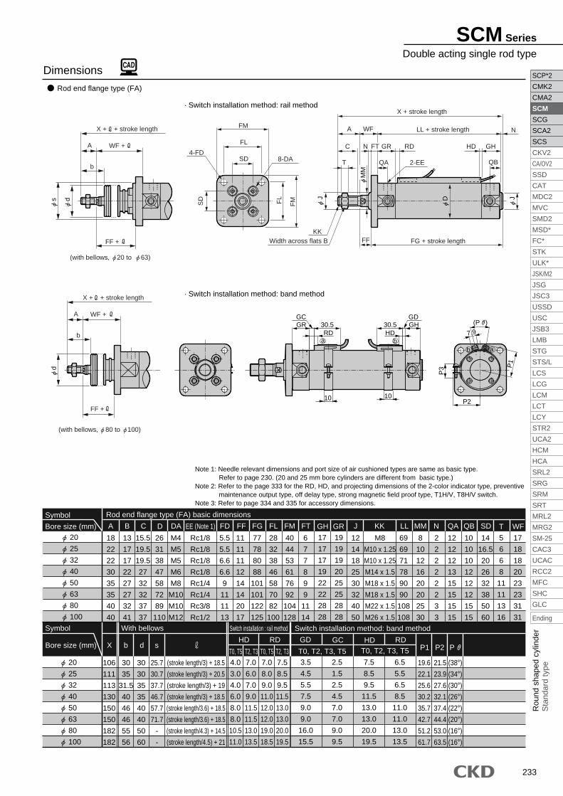
Basic type (00) 20 to 100<Rubber cushioned>
Note 1: Refer to the page 333 for the RD, HD, and projecting dimensions of the 2-color indicator type, preventive maintenance output type, off delay type, strong magnetic field proof type, T1H/V, T8H/V switch.Note 2: Refer to page 334 and 335 for accessory dimensions.
<Air cushioned>
· Switch installation method: band method
· Switch installation method: band method
Dimensions
20
25
32
40
50
63
80
100
Symbol
Bore size (mm)
3.5
4.5
5.5
7.5
9.0
9.0
16.0
15.5
T0, T2, T3, T5 T0, T2, T3, T5
GDGH P1 P2 P GR
GC
Switch installation method: band method
2.5
1.5
2.5
4.5
7.0
7.0
9.0
9.5
17
17
17
19
22
22
28
28
19
19
19
20
25
25
28
28
7.5
8.5
9.5
11.5
13.0
13.0
20.0
19.5
HD
6.5
5.5
6.5
8.5
11.0
11.0
13.0
13.5
RD
19.6
22.1
25.6
30.2
35.7
42.7
51.2
61.7
21.5
23.9
27.6
32.1
37.4
44.4
53.0
63.5
(38°)
(34°)
(30°)
(26°)
(22°)
(20°)
(16°)
(16°)
(P )
7.9
P1
P2
P3
ba
RD30.5GR
GC
aHD
30.5 GHGD
b
1010
HD30.5 GH
GD
RD30.5GR
GC(P )
7.9ba
1010
P1
ba
P3
P2
SCM Series
Dimensions

232
Axial foot type (LB)
Note 1: Needle relevant dimensions and port size of air cushioned types are same as basic type. Refer to page 230. (20 and 25 mm bore cylinders are different from basic type.)Note 2: Refer to the page 333 for the RD, HD, and projecting dimensions of the 2-color indicator type, preventive maintenance output type, off delay type, strong magnetic field proof type, T1H/V, T8H/V switch.Note 3: Refer to page 334 and 335 for accessory dimensions.
3.5
4.5
5.5
7.5
9.0
9.0
16.0
15.5
T0, T2, T3, T5
2.5
1.5
2.5
4.5
7.0
7.0
9.0
9.5
T0, T2, T3, T5
7.5
8.5
9.5
11.5
13.0
13.0
20.0
19.5
6.5
5.5
6.5
8.5
11.0
11.0
13.0
13.5
Dimensions
20
25
32
40
50
63
80
100
Symbol
Bore size (mm)
18
22
22
30
35
35
40
40
15.5
19.5
19.5
27
32
32
37
37
26
31
38
47
58
72
89
110
A
13
17
17
22
27
27
32
41
B C
28.9
29.9
30.9
33.4
40.5
40.5
55
55
LF
20
22
25
30
40
45
55
65
LH
69
69
71
78
90
90
108
108
LL
32
36
44
54
66
82
100
120
LR
M4
M5
M5
M6
M8
M10
M10
M12
DA
Rc1/8
Rc1/8
Rc1/8
Rc1/8
Rc1/4
Rc1/4
Rc3/8
Rc1/2
EE (Note 1)
44
49
58
71
86
106
125
150
LS
3.2
3.2
3.2
3.2
4.5
4.5
4.5
6
LT
45.2
45.2
45.2
51.2
55
55
60
60
LX
2.6
3.4
3.4
4
5
5
6
7
M
8
10
12
16
20
20
25
30
MM
12
12
12
13
15
15
15
15
QA
M8
M10 x 1.25
M10 x 1.25
M14 x 1.5
M18 x 1.5
M18 x 1.5
M22 x 1.5
M26 x 1.5
KK
7.1
7.1
8.1
9.1
11
13
14
16
LC
15.1
15.1
16.1
16.6
22
22
28.5
30
LB
109.8
115.6
117.6
135.2
157.5
157.5
189.5
192
LA
5.7
5.7
6.8
6.8
9
11
11
14
LDD
4
4
4
4
5
5
6
6
LE
10
10
10
12
12
12
15
15
14
16.5
20
26
32
38
50
60
5
6
6
8
11
11
13
16
QB SD
19
19
19
20
25
25
28
28
GR
19.5
22
25.5
30
35.5
42.5
51
61.5
P
18
18
18
18
18
18
18
18
GA
23
24.4
25
25.7
26.2
26.5
26.7
26.7
GB
10
10
10
10
17.5
17.5
20
20
W
17
18
18
20
23
23
31
31
WF
30
35
31.5
40
46
46
55
56
b
Stroke length/3) + 18.5
(stroke length/3) + 20.5
(stroke length/3) + 19
(stroke length/3) + 18.5
(stroke length/3.6) + 18.5
(stroke length/3.6) + 18.5
(stroke length/4.3) + 14.5
(stroke length/4.5) + 21
d
30
30
35
35
40
40
50
60
T0, T5 T2, T3 T0, T5
HD RD GD GC
T2, T3
25.7
30.7
37.7
46.7
57.7
71.7
-
-
sT
17
17
17
19
22
22
28
28
GH
Axial foot type (LB) basic dimensions
20
25
32
40
50
63
80
100
Symbol Switch installation method: rail methodWith bellows
Bore size (mm)
20
25
32
40
50
63
80
100
Symbol
Switch installation method: band method
Bore size (mm)HD RD
19.6
22.1
25.6
30.2
35.7
42.7
51.2
61.7
P1
21.5
23.9
27.6
32.1
37.4
44.4
53.0
63.5
P2
(38°)
(34°)
(30°)
(26°)
(22°)
(20°)
(16°)
(16°)
P
· Switch installation method: rail method
· Switch installation method: band method
4.0
3.0
4.0
6.0
8.0
8.0
10.5
11.0
7.0
6.0
7.0
9.0
11.5
11.5
13.0
13.5
7.0
8.0
9.0
11.0
12.0
12.0
19.0
18.5
7.5
8.5
9.5
11.5
13.0
13.0
20.0
19.5
d
LT
LH
4- LD
s
A
b
WF +
LF +
LA + + stroke length
d
A
b
WF +
LF +
LA + + stroke length
MM
D
C GR GH
QBQAT
RD HD
2-EE
KK
A
MM
WW
LBLB
LF
LCLC
WF LL + stroke length
LA + stroke length
LX + stroke length
2- LE
Dowel pin position Dowel pin position
SD
SD
8-DA
LSLR
GA
P
GB
(with bellows, 20 to 63)
(with bellows, 80 to 100)
Width across flats B
(P )
7.9
P1
P3
P2
ba
RD30.5GR
GC
a bHD30.5 GH
GD
1010
SCM Series
SCP*2
CMK2
CMA2
SCM
SCG
SCA2
SCS
CKV2
CA/OV2
SSD
CAT
MDC2
MVC
SMD2
MSD*
FC*
STK
ULK*
JSK/M2
JSG
JSC3
USSD
USC
JSB3
LMB
STG
STS/L
LCS
LCG
LCM
LCT
LCY
STR2
UCA2
HCM
HCA
SRL2
SRG
SRM
SRT
MRL2
MRG2
SM-25
CAC3
UCAC
RCC2
MFC
SHC
GLC
Ending
233
SCP*2
CMK2
CMA2
SCM
SCG
SCA2
SCS
CKV2
CA/OV2
SSD
CAT
MDC2
MVC
SMD2
MSD*
FC*
STK
ULK*
JSK/M2
JSG
JSC3
USSD
USC
JSB3
LMB
STG
STS/L
LCS
LCG
LCM
LCT
LCY
STR2
UCA2
HCM
HCA
SRL2
SRG
SRM
SRT
MRL2
MRG2
SM-25
CAC3
UCAC
RCC2
MFC
SHC
GLC
Ending
Rou
nd s
hape
d cy
linde
rS
tand
ard
type
Rod end flange type (FA)
3.5
4.5
5.5
7.5
9.0
9.0
16.0
15.5
T0, T2, T3, T5 T0, T2, T3, T5
2.5
1.5
2.5
4.5
7.0
7.0
9.0
9.5
7.5
8.5
9.5
11.5
13.0
13.0
20.0
19.5
6.5
5.5
6.5
8.5
11.0
11.0
13.0
13.5
T0, T5 T2, T3 T0, T5 T2, T3
Dimensions
106
111
113
130
150
150
182
182
30
35
31.5
40
46
46
55
56
b
30
30
35
35
40
40
50
60
d
25.7
30.7
37.7
46.7
57.7
71.7
-
-
s
(stroke length/3) + 18.5
(stroke length/3) + 20.5
(stroke length/3) + 19
(stroke length/3) + 18.5
(stroke length/3.6) + 18.5
(stroke length/3.6) + 18.5
(stroke length/4.3) + 14.5
(stroke length/4.5) + 21
RDHDX
20
25
32
40
50
63
80
100
Symbol Switch installation : rail method Switch installation method: band methodWith bellows
Bore size (mm)GD GC HD RD
19.6
22.1
25.6
30.2
35.7
42.7
51.2
61.7
P1
21.5
23.9
27.6
32.1
37.4
44.4
53.0
63.5
P2
(38°)
(34°)
(30°)
(26°)
(22°)
(20°)
(16°)
(16°)
P
· Switch installation method: rail method
· Switch installation method: band method
Note 1: Needle relevant dimensions and port size of air cushioned types are same as basic type. Refer to page 230. (20 and 25 mm bore cylinders are different from basic type.)Note 2: Refer to the page 333 for the RD, HD, and projecting dimensions of the 2-color indicator type, preventive maintenance output type, off delay type, strong magnetic field proof type, T1H/V, T8H/V switch.Note 3: Refer to page 334 and 335 for accessory dimensions.
4.0
3.0
4.0
6.0
8.0
8.0
10.5
11.0
7.0
6.0
7.0
9.0
11.5
11.5
13.0
13.5
7.0
8.0
9.0
11.0
12.0
12.0
19.0
18.5
7.5
8.5
9.5
11.5
13.0
13.0
20.0
19.5
20
25
32
40
50
63
80
100
Symbol
Bore size (mm)
18
22
22
30
35
35
40
40
15.5
19.5
19.5
27
32
32
37
37
26
31
38
47
58
72
89
110
A
13
17
17
22
27
27
32
41
B C
M8
M10 x 1.25
M10 x 1.25
M14 x 1.5
M18 x 1.5
M18 x 1.5
M22 x 1.5
M26 x 1.5
KK
69
69
71
78
90
90
108
108
LL
M4
M5
M5
M6
M8
M10
M10
M12
DA
Rc1/8
Rc1/8
Rc1/8
Rc1/8
Rc1/4
Rc1/4
Rc3/8
Rc1/2
EE (Note 1)
8
10
12
16
20
20
25
30
MM
2
2
2
2
2
2
3
3
N
12
12
12
13
15
15
15
15
QA
10
10
10
12
12
12
15
15
QB SD
14
16.5
20
26
32
38
50
60
FD
28
32
38
46
58
70
82
100
5.5
5.5
6.6
6.6
9
11
11
13
FL
77
78
80
88
101
101
122
125
FG
11
11
11
12
14
14
20
17
FF
40
44
53
61
76
92
104
128
FMD
6
7
7
8
9
9
11
14
FT
12
14
18
25
30
32
40
50
JGH
17
17
17
19
22
22
28
28
19
19
19
20
25
25
28
28
GR
Rod end flange type (FA) basic dimensions
5
6
6
8
11
11
13
16
T
17
18
18
20
23
23
31
31
WF
MM
J D J
C N GRFT GH
QBQAT
RD HD
2-EE
KKFF
A NWFFM
8-DA4-FD
FM
FL
FL
SD
SD
X + stroke length
LL + stroke length
FG + stroke length
ds
A
b
WF +
FF +
X + + stroke length
d
A
b
WF +
FF +
X + + stroke length
(with bellows, 20 to 63)
(with bellows, 80 to 100)
Width across flats B
HD30.5 GH
GD
RD30.5GR
GC
ba
(P )
7.9
P1
P3
P2
b a
1010
SCM Series
Double acting single rod type

234
Head end flange type (FB)
3.5
4.5
5.5
7.5
9.0
9.0
16.0
15.5
T0, T2, T3, T5
2.5
1.5
2.5
4.5
7.0
7.0
9.0
9.5
T0, T2, T3, T5
7.5
8.5
9.5
11.5
13.0
13.0
20.0
19.5
6.5
5.5
6.5
8.5
11.0
11.0
13.0
13.5
Dimensions
T0, T5 T2, T3 T0, T5 T2, T3
30
35
31.5
40
46
46
55
56
b
30
30
35
35
40
40
50
60
d
25.7
30.7
37.7
46.7
57.7
71.7
88.7
109.7
s
(stroke length/3) + 18.5
(stroke length/3) + 20.5
(stroke length/3) + 19
(stroke length/3) + 18.5
(stroke length/3.6) + 18.5
(stroke length/3.6) + 18.5
(stroke length/4.3) + 14.5
(stroke length/4.5) + 21
RDHD
20
25
32
40
50
63
80
100
Symbol Switch installation: rail method Switch installation method: band methodWith bellows
Bore size (mm)GD GC HD RD
19.6
22.1
25.6
30.2
35.7
42.7
51.2
61.7
P1
21.5
23.9
27.6
32.1
37.4
44.4
53.0
63.5
P2
(38°)
(34°)
(30°)
(26°)
(22°)
(20°)
(16°)
(16°)
P
Note 1: Needle relevant dimensions and port size of air cushioned types are same as basic type.Refer to page 230. (20 and 25 mm bore cylinders are different from basic type.)
Note 2: Refer to the page 333 for the RD, HD, and projecting dimensions of the 2-color indicator type, preventive maintenance output type, off delay type, strong magnetic field proof type, T1H/V, T8H/V switch.
Note 3: Refer to page 334 and 335 for accessory dimensions.
· Switch installation method: rail method
· Switch installation method: band method
4.0
3.0
4.0
6.0
8.0
8.0
10.5
11.0
7.0
6.0
7.0
9.0
11.5
11.5
13.0
13.5
7.0
8.0
9.0
11.0
12.0
12.0
19.0
18.5
7.5
8.5
9.5
11.5
13.0
13.0
20.0
19.5
20
25
32
40
50
63
80
100
Symbol
Bore size (mm)
18
22
22
30
35
35
40
40
15.5
19.5
19.5
27
32
32
37
37
26
31
38
47
58
72
89
110
A
13
17
17
22
27
27
32
41
B C
M8
M10 x 1.25
M10 x 1.25
M14 x 1.5
M18 x 1.5
M18 x 1.5
M22 x 1.5
M26 x 1.5
KK
69
69
71
78
90
90
108
108
LL
M4
M5
M5
M6
M8
M10
M10
M12
DA
Rc1/8
Rc1/8
Rc1/8
Rc1/8
Rc1/4
Rc1/4
Rc3/8
Rc1/2
EE (Note 1)
8
10
12
16
20
20
25
30
MM
2
2
2
2
2
2
3
3
N
12
12
12
13
15
15
15
15
QA
10
10
10
12
12
12
15
15
QB SD
14
16.5
20
26
32
38
50
60
FA
28
32
38
46
58
70
82
100
112
118
120
138
159
159
193
196
FL
92
94
96
106
122
122
150
153
FJ
5.5
5.5
6.6
6.6
9
11
11
13
FD
40
44
53
61
76
92
104
128
FMD
6
7
7
8
9
9
11
14
FT JGH
17
17
17
19
22
22
28
28
19
19
19
20
25
25
28
28
12
14
18
25
30
32
40
50
GR
Rod end flange type (FB) basic dimensions
5
6
6
8
11
11
13
16
T17
18
18
20
23
23
31
31
WF
(with bellows)
MM
J D Jds
C N GR GH
QBQAT
RD HD
2-EE
KK
A NFTWF
A
b
WF +
FA + + stroke length
FA + stroke length
LL + stroke length
FJ + stroke length
FM
8-DA4-FD
FM
FL
FL
SD
SD
Width across flats B
(P )
7.9
P1
P3
P2
ba
10
HD30.5 GH
GD
RD30.5GR
10
GC
ba
FJ + + stroke length
SCM Series
SCP*2
CMK2
CMA2
SCM
SCG
SCA2
SCS
CKV2
CA/OV2
SSD
CAT
MDC2
MVC
SMD2
MSD*
FC*
STK
ULK*
JSK/M2
JSG
JSC3
USSD
USC
JSB3
LMB
STG
STS/L
LCS
LCG
LCM
LCT
LCY
STR2
UCA2
HCM
HCA
SRL2
SRG
SRM
SRT
MRL2
MRG2
SM-25
CAC3
UCAC
RCC2
MFC
SHC
GLC
Ending

236
With bellows Switch installation method: rail method
Q QA
Symbol
Bore size (mm)
Symbol
Bore size (mm)
Switch installation method: band method
3.5
4.5
5.5
7.5
9.0
9.0
T0, T2, T3, T52.5
1.5
2.5
4.5
7.0
7.0
T0, T2, T3, T5
7.5
8.5
9.5
11.5
13.0
13.0
6.5
5.5
6.5
8.5
11.0
11.0
Symbol
Bore size (mm) A C DA EE (Note 1)CD J KK LL MMCE CJCICT CMCA CN D
Eye bracket type (CA) basic dimensions
B
Dimensions ( 20 to 63)
Eye bracket type (CA)
Note 1: Needle relevant dimensions and port size of air cushioned types are same as basic type. Refer to page 230. (20 and 25 mm bore cylinders are different from basic type.)Note 2: Refer to the page 333 for the RD, HD, and projecting dimensions of the 2-color indicator type, preventive maintenance output type, off delay type, strong magnetic field proof type, T1H/V, T8H/V switch.Note 3: Refer to page 334 and 335 for accessory dimensions.
20
25
32
40
50
63
19.5
22
25.5
30
35.5
42.5
18
18
18
18
18
18
10
10
10
12
12
12
14
16.5
20
26
32
38
5
6
6
8
11
11
23
24.4
25
25.7
26.2
26.5
25.7
30.7
37.7
46.7
57.7
71.7
17
18
18
20
23
23
30
30
35
35
40
40
30
35
31.5
40
46
46
(stroke length/3) + 18.5
(stroke length/3) + 20.5
(stroke length/3) + 19
(stroke length/3) + 18.5
(stroke length/3.6) + 18.5
(stroke length/3.6) + 18.5
· Switch installation method: rail method
13
15.5
19
23.5
29
36
12
12
12
13
15
15
P GA GBT0, T5 T2, T3 T0, T5 T2, T3
QB SD T WF sdb
Switch installation: band method
HD RD GD GC
20
25
32
40
50
63
19.6
22.1
25.6
30.2
35.7
42.7
21.5
23.9
27.6
32.1
37.4
44.4
P1 P2
(38°)
(34°)
(30°)
(26°)
(22°)
(20°)
PHD RD
· Switch installation method: band method
4.0
3.0
4.0
6.0
8.0
8.0
7.0
6.0
7.0
9.0
11.5
11.5
7.0
8.0
9.0
11.0
12.0
12.0
7.5
8.5
9.5
11.5
13.0
13.0
20
25
32
40
50
63
18
22
22
30
35
35
15.5
19.5
19.5
27
32
32
129
138
145.5
167.5
192.5
199.5
M4
M5
M5
M6
M8
M10
Rc1/8
Rc1/8
Rc1/8
Rc1/8
Rc1/4
Rc1/4
M8
M10 x 1.25
M10 x 1.25
M14 x 1.5
M18 x 1.5
M18 x 1.5
69
69
71
78
90
90
8
10
12
16
20
20
100
103
108.5
119.5
137.5
142.5
11
13
15
18
20
22
10.8
12.8
15.5
17.5
19
22
3.2
3.2
4.5
4.5
6
8
29
33
40
49
60
74
38.6
42.6
54
65
79.6
97.8
26
31
38
47
58
72
17
17
17
19
22
22
13
17
17
22
27
27
8
10
12
14
16
18
GH
19
19
19
20
25
25
12
14
18
25
30
32
GR
MM
J
CDe8 (pin O.D.)
Dds
C 2 GR GH
QA QBT
RD HD
KK
A WF
CN
CM
GBCT
GA
SD 0.1
SD
0
.1
QP
8-DA
CI
A
b
WF +
CA + + stroke length
CJ + + stroke length
CA + stroke length
CJ + stroke length
LL + stroke length
Width across flats B
(with bellows)
RCE
2-EE
7.9
(P )
P1
baba
b a
P2
P3
RD HD
30.5GRGC
30.5 GH
GD
1010
SCM Series
SCP*2
CMK2
CMA2
SCM
SCG
SCA2
SCS
CKV2
CA/OV2
SSD
CAT
MDC2
MVC
SMD2
MSD*
FC*
STK
ULK*
JSK/M2
JSG
JSC3
USSD
USC
JSB3
LMB
STG
STS/L
LCS
LCG
LCM
LCT
LCY
STR2
UCA2
HCM
HCA
SRL2
SRG
SRM
SRT
MRL2
MRG2
SM-25
CAC3
UCAC
RCC2
MFC
SHC
GLC
Ending

237
SCP*2
CMK2
CMA2
SCM
SCG
SCA2
SCS
CKV2
CA/OV2
SSD
CAT
MDC2
MVC
SMD2
MSD*
FC*
STK
ULK*
JSK/M2
JSG
JSC3
USSD
USC
JSB3
LMB
STG
STS/L
LCS
LCG
LCM
LCT
LCY
STR2
UCA2
HCM
HCA
SRL2
SRG
SRM
SRT
MRL2
MRG2
SM-25
CAC3
UCAC
RCC2
MFC
SHC
GLC
Ending
Rou
nd s
hape
d cy
linde
rS
tand
ard
type
Note 1: Needle relevant dimensions and port size of air cushioned types are same as basic type. Refer to page 230. (20 and 25 mm bore cylinders are different from basic type.)Note 2: Refer to the page 333 for the RD, HD, and projecting dimensions of the 2-color indicator type, preventive maintenance output type, off delay type, strong magnetic field proof type, T1H/V, T8H/V switch.Note 3: Refer to page 334 and 335 for accessory dimensions.
20
25
32
40
50
63
19.5
22
25.5
30
35.5
42.5
P
18
18
18
18
18
18
GA
23
24.4
25
25.7
26.2
26.5
GBHD RD
T0, T5 T2, T3 T0, T5 T2, T3
(stroke length/3) + 18.5
(stroke length/3) + 20.5
(stroke length/3) + 19
(stroke length/3) + 18.5
(stroke length/3.6) + 18.5
(stroke length/3.6) + 18.5
With bellows Switch installation method: rail method
M8
M10 x 1.25
M10 x 1.25
M14 x 1.5
M18 x 1.5
M18 x 1.5
KK
69
69
71
78
90
90
LL MM
8
10
12
16
20
20
12
12
12
13
15
15
QA
10
10
10
12
12
12
QB
5
6
6
8
11
11
T WF
17
18
18
20
23
23
30
35
31.5
40
46
46
b
30
30
35
35
40
40
d
25.7
30.7
37.7
46.7
57.7
71.7
s
Symbol
Bore size (mm)
Symbol
Bore size (mm)
Switch installation method: band method
4.0
3.0
4.0
6.0
8.0
8.0
7.0
6.0
7.0
9.0
11.5
11.5
7.0
8.0
9.0
11.0
12.0
12.0
7.5
8.5
9.5
11.5
13.0
13.0
3.5
4.5
5.5
7.5
9.0
9.0
T0, T2, T3, T5
2.5
1.5
2.5
4.5
7.0
7.0
T0, T2, T3, T57.5
8.5
9.5
11.5
13.0
13.0
6.5
5.5
6.5
8.5
11.0
11.0
20
25
32
40
50
63
18
22
22
30
35
35
15.5
19.5
19.5
27
32
32
42
42
48
56
64
74
3.2
3.2
4.5
4.5
6
8
5.5
5.5
6.6
6.6
9
11
10
10
10
10
20
20
26
31
38
47
58
72
M4
M5
M5
M6
M8
M10
Rc1/8
Rc1/8
Rc1/8
Rc1/8
Rc1/4
Rc1/4
25
30
35
40
50
60
139
146
154.5
177.5
204.5
214.5
38
45.5
54
63.5
79
96
29
33
40
49
60
74
43.4
48
59.4
71.4
86
105.4
28
28
28
30
36
46
10.8
12.8
15.5
17.5
19
22
100
103
108.5
119.5
137.5
142.5
35.8
39.8
49.4
58.4
72.4
90.4
16
20
22
30
36
46
13
17
17
22
27
27
19
19
19
20
25
25
12
14
18
25
30
32
17
17
17
19
22
22
Symbol
Bore size (mm) A C CT CV CW D DA EE (Note 1)CK CPCOCM CQCG CH CI CJ CR CS
Eye bracket type (CA) with bracket (option symbol B2) basic dimensions
B GRGH J
Dimensions ( 20 to 63)
Eye bracket type (CA) with bracket (option symbol B2)
· Switch installation method: rail method
· Switch installation method: band method
GD GC
20
25
32
40
50
63
19.6
22.1
25.6
30.2
35.7
42.7
21.5
23.9
27.6
32.1
37.4
44.4
P1 P2
(38°)
(34°)
(30°)
(26°)
(22°)
(20°)
PHD RD
Switch installation: band method
MM
CW4- CV
J Dds
C 2 GR GH
QA QBT
RD HD
KK
A WF
CQ
CM
GB CT
GA
CP C
0
P
8-DA
CI
CH
CG
A
b
WF +
CK + + stroke length
CJ + + stroke length
CK + stroke length
CJ + stroke length
LL + stroke length
CR
CS
CT
+0.05 0
(with bellows)
2-EE
Width across flats B
7.9
(P )
baRD HD
30.5GR
GC
30.5 GH
GD
P1
ba
P2
P3
1010
b a
SCM Series
Dimensions

238
Dimensions ( 80 to 100)
Clevis bracket type (CB) · Switch installation method: rail method
· Switch installation method: band method
Note 1: Needle relevant dimensions and port size of air cushioned types are same as basic type. Refer to page 230.Note 2: Refer to the page 333 for the RD, HD, and projecting dimensions of the 2-color indicator type, preventive maintenance output type, off delay type, strong magnetic field proof type, T1H/V, T8H/V switch.Note 3: Refer to page 334 and 335 for accessory dimensions.
80
100
Symbol
Bore size (mm)
50
60
dT0, T5T0, T5 T2, T3 T2, T3
88.7
109.7
s
51.2
61.7
53.0
63.5
P1 P2
(16°)
(16°)
P
(stroke length/4.3) + 14.5
(stroke length/4.5) + 21
51
61.5
PHD RD GD GC HD RD
With bellows Switch installation method: rail method Switch installation method: band method
55
56
b
10.5
11.0
13.0
13.5
19.0
18.5
20.0
19.5
16.0
15.5
T0, T2, T3, T59.0
9.5
T0, T2, T3, T520.0
19.5
13.0
13.5
80
100
Symbol
Bore size (mm)174
182
CJ
25
31
CI
28
32
CX
80
100
CM
56
64
CY
64
72
CZ
89
110
D
M10
M12
DA
Rc3/8
Rc1/2
EE (Note 1)
40
50
J
25
30
MM
M22 x 1.5
M26 x 1.5
KK
32
41
18
22
B CD
232
244
CA
18
22
CE
35
43
CF
Clevis bracket type (CB) basic dimensions
44.5
55
Q
13
16
T
50
60
SD
(with bellows)
MM
JCDe8(Pin O.D.)
Dds
37 3 28 28
15 15T
RD HD
2-EE
KK
40 31 CF
CZ
CY
26.7
18
SD
SD
CX
CM
PQ
8-DA
RCE
CIA
b
31 +
CA + + stroke length
CJ + + stroke length
CA + stroke length
CJ + stroke length
108 + stroke length
Width across flats B+0.5+0.3
HD30.5 GD 28
bRD
30.5GC28
a
1010
P1
P2
7.9(P )
b a
P3
SCM Series
SCP*2
CMK2
CMA2
SCM
SCG
SCA2
SCS
CKV2
CA/OV2
SSD
CAT
MDC2
MVC
SMD2
MSD*
FC*
STK
ULK*
JSK/M2
JSG
JSC3
USSD
USC
JSB3
LMB
STG
STS/L
LCS
LCG
LCM
LCT
LCY
STR2
UCA2
HCM
HCA
SRL2
SRG
SRM
SRT
MRL2
MRG2
SM-25
CAC3
UCAC
RCC2
MFC
SHC
GLC
Ending

239
SCP*2
CMK2
CMA2
SCM
SCG
SCA2
SCS
CKV2
CA/OV2
SSD
CAT
MDC2
MVC
SMD2
MSD*
FC*
STK
ULK*
JSK/M2
JSG
JSC3
USSD
USC
JSB3
LMB
STG
STS/L
LCS
LCG
LCM
LCT
LCY
STR2
UCA2
HCM
HCA
SRL2
SRG
SRM
SRT
MRL2
MRG2
SM-25
CAC3
UCAC
RCC2
MFC
SHC
GLC
Ending
Rou
nd s
hape
d cy
linde
rS
tand
ard
type
Dimensions ( 80 to 100)
· Switch installation method: band method
Clevis bracket type (CB) with bracket (option symbol B1)· Switch installation method: rail method
Note 1: Needle relevant dimensions and port size of air cushioned types are same as basic type. Refer to page 230.Note 2: Refer to the page 333 for the RD, HD, and projecting dimensions of the 2-color indicator type, preventive maintenance output type, off delay type, strong magnetic field proof type, T1H/V, T8H/V switch.Note 3: Refer to page 334 and 335 for accessory dimensions.
80
100
Symbol
Bore size (mm)
13
16
T
50
60
SD
55
56
b
50
60
dT0, T5T0, T5 T2, T3 T2, T3
88.7
109.7
s
(Stroke length/4.3) + 14.5
(Stroke length/4.5) + 21
51
61.5
PHD RD GD GC HD RD
108
108
LL
25
30
MM
3
3
N
With bellows Switch installation method: rail method Switch installation method: band method
80
100
Symbol
Bore size (mm)174
182
CJ
25
31
CI
45
60
CH
72
93
CG
272.5
298.5
CK
80
100
CM
M10
M12
DA
Rc3/8
Rc1/2
EE (Note 1)
55
65
CP
110
130
CQ
85
100
CS
11
12
CT
11
13.5
CV
28
32
CX
56
64
CY
64
72
CZ
89
100
D
40
50
J
32
41
B CD
18
22
18
22
CE
35
43
CF
Clevis bracket type (CB) with bracket (option symbol B2) basic dimensions
M22 x 1.5
M26 x 1.5
KK
80
100
Symbol
Bore size (mm)
(16°)
(16°)
P
51.2
61.7
P1
53.0
63.5
P2
10.5
11.0
13.0
13.5
19.0
18.5
20.0
19.5
16.0
15.5
T0, T2, T3, T5
9.0
9.5
T0, T2, T3, T5
20.0
19.5
13.0
13.5
MM
J Dd
4- CV
s
37 N 28 28
15 15T
RD HD
2-EE
KK
40 31 CF
CH
CG
CZ
CY
26.7
18
SD
SD
CX
CM
PC
P
CT
8-DACI40
b
31 +
CK + + stroke length
CJ + + stroke length
CK + stroke length
CJ + stroke length
LL + stroke length
CS
CQ
(with bellows)
CDe8(Pin O.D.)
RCE
Width across flats B
HD30.5 GD 28
RD30.5GC28
ba
1010P
1
7.9
P2
(P )
b aP
3
SCM Series
Dimensions

240
3.54.55.57.59.09.0
T0, T2, T3, T52.51.52.54.57.07.0
T0, T2, T3, T57.58.59.5
11.513.013.0
6.55.56.58.5
11.011.0
Dimensions (φ20 to φ63)
Rod end trunnion type (TA) · Switch installation method: rail method
· Switch installation method: band method
Note 1: Needle relevant dimensions and port size of air cushioned types are same as basic type. Refer to page 230. (20 and 25 mm bore cylinders are different from basic type.)Note 2: Refer to the page 333 for the RD, HD, and projecting dimensions of the 2-color indicator type, preventive maintenance output type, off delay type, strong magnetic field proof type, T1H/V, T8H/V switch.Note 3: Configuration is made from a collar, plain washer and hexagon socket head cap bolt.Note 4: Refer to page 334 and 335 for accessory dimensions.
3943
54.565.98098
47.653
67.781.198.6
119.2
TM TN
Symbol
Bore size (mm) TT
81012141618
106111113130150150
X
171818202323
WF
19.622.125.630.235.742.7
P1
21.523.927.632.137.444.4
P2
(38°)(34°)(30°)(26°)(22°)(20°)
P
3035
31.5404646
b
303035354040
d
25.730.737.746.757.771.7
sT0, T5T0, T5 T2, T3 T2, T3
(stroke length/3) + 18.5(stroke length/3) + 20.5(stroke length/3) + 19
(stroke length/3) + 18.5(stroke length/3.6) + 18.5(stroke length/3.6) + 18.5
19.522
25.530
35.542.5
P
181818181818
GA
2324.425
25.726.226.5
GBHD RD
With bellows Switch installation method: rail method
Symbol
Bore size (mm)
Switch installation method: band methodGD GC HD RD
4.03.04.06.08.08.0
7.06.07.09.0
11.511.5
7.08.09.0
11.012.012.0
7.58.59.511.513.013.0
202532405063
202532405063
202532405063
SymbolBore size (mm)
M8M10 x 1.25M10 x 1.25M14 x 1.5M18 x 1.5M18 x 1.5
696971789090
81012162020
121212131515
101010121212
5668
1111
282929323636
606062687979
283340496074
182222303535
15.519.519.5273232
Rc1/8Rc1/8Rc1/8Rc1/8Rc1/4Rc1/4
263138475872
Rod end trunnion type (TA) basic dimensions
131717222727
KK LL MM QA QB T TF TG TLA C EE (Note 1)D JB171717192222
GH191919202525
121418253032
GR
MM
J J
2-
TT
e8
(Col
lar
O.D
.)
Dds
TLBracket installation
Range
GB
GA
C 2 GR GH
QBQAT
RD HD2-EE
KK
Note 4
A 2WFA
b
WF +
X + + stroke length
TF +
X + stroke length
TG + stroke lengthTF
LL + stroke length
P
TN
TM
(with bellows)
Width across flats B
ba
RD
30.5GR
GC
a
10
HD
30.5 GHGD
b
10
P3
P2
(P )
7.9
b a
P1
SCM Series
SCP*2
CMK2
CMA2
SCM
SCG
SCA2
SCS
CKV2
CA/OV2
SSD
CAT
MDC2
MVC
SMD2
MSD*
FC*
STK
ULK*
JSK/M2
JSG
JSC3
USSD
USC
JSB3
LMB
STG
STS/L
LCS
LCG
LCM
LCT
LCY
STR2
UCA2
HCM
HCA
SRL2
SRG
SRM
SRT
MRL2
MRG2
SM-25
CAC3
UCAC
RCC2
MFC
SHC
GLC
Ending

241
SCP*2
CMK2
CMA2
SCM
SCG
SCA2
SCS
CKV2
CA/OV2
SSD
CAT
MDC2
MVC
SMD2
MSD*
FC*
STK
ULK*
JSK/M2
JSG
JSC3
USSD
USC
JSB3
LMB
STG
STS/L
LCS
LCG
LCM
LCT
LCY
STR2
UCA2
HCM
HCA
SRL2
SRG
SRM
SRT
MRL2
MRG2
SM-25
CAC3
UCAC
RCC2
MFC
SHC
GLC
Ending
Rou
nd s
hape
d cy
linde
rS
tand
ard
type
4.03.04.06.08.08.0
7.06.07.09.011.511.5
7.08.09.0
11.012.012.0
7.58.59.5
11.513.013.0
3.54.55.57.59.09.0
T0, T2, T3, T52.51.52.54.57.07.0
T0, T2, T3, T57.58.59.511.513.013.0
6.55.56.58.511.011.0
Dimensions (φ20 to φ63)
· Switch installation method: band method
Rod end trunnion type (TA) with bracket (option symbol: B2)· Switch installation method: rail method
Note 1: Needle relevant dimensions and port size of air cushioned types are same as basic type. Refer to page 230. (20 and 25 mm bore cylinders are different from basic type.)Note 2: Refer to the page 333 for the RD, HD, and projecting dimensions of the 2-color indicator type, preventive maintenance output type, off delay type, strong magnetic field proof type, T1H/V, T8H/V switch.Note 3: Refer to page 334 and 335 for accessory dimensions.
202532405063
Symbol
Bore size (mm)
3035
31.5404646
b
106111113130150150
X
171818202323
WF
303035354040
d
25.730.737.746.757.771.7
s T0, T5T0, T5 T2, T3 T2, T3(stroke length/3) + 18.5(stroke length/3) + 20.5(stroke length/3) + 19
(stroke length/3) + 18.5(stroke length/3.6) + 18.5(stroke length/3.6) + 18.5
19.522
25.530
35.542.5
P
181818181818
GA
2324.425
25.726.226.5
GBHD RD
TT
With bellows Switch installation method: rail method
Switch installation method: band method
56681111
T
282929323636
TF
606062687979
TG
283340496074
TL
3943
54.565.98098
TM
47.653
67.781.198.6119.2
TN
81012141618
202532405063
Symbol
Bore size (mm)
19.622.125.630.235.742.7
P1
21.523.927.632.137.444.4
P2
(38°)(34°)(30°)(26°)(22°)(20°)
P θGD GC HD RD
171717192222
GH191919202525
GR202532405063
SymbolBore size (mm)
M8M10 x 1.25M10 x 1.25M14 x 1.5M18 x 1.5M18 x 1.5
KK696971789090
LL81012162020
MM121212131515
QA101010121212
QB182222303535
A131717222727
B15.519.519.5273232
C424248566474
CG282828303646
CH253035405060
CP35.839.849.458.472.490.4
CR162022303646
CS3.23.24.54.568
CT5.55.56.66.6911
CV101010102020
CWRc1/8Rc1/8Rc1/8Rc1/8Rc1/4Rc1/4
EE (Note 1)263138475872
D JRod end trunnion type (TA) with bracket (option symbol B2) basic dimensions
121418253032
MM
J
φD
C 2 GR GH
QBQAT
RD HD2-EE
KK
A 2WF
X + stroke length
TG + stroke length
LL + stroke length
2-
TT
e8
4- CV CW
(Col
lar
O.D
.)
ds
TL
GB
GA
A
b
WF +
TF +
X + + stroke length
P
CTCP
TN
TM
CS
CR +0.05 0
CH
CGTF(with bellows)
Width across flats B
ba
RD
30.5GR
GC
aHD
30.5 GHGD
b
1010P2
P1
7.9
(P )
b a
P3
SCM Series
Dimensions

242
X + + stroke length
Dimensions ( 20 to 63)
Head end trunnion type (TB) · Switch installation method: rail method
· Switch installation method: band method
(with bellows)
MM
J J
2-
TT
e8
(Col
lar
O.D
.)
Dds
TLBracket
installation range
GB
GA
C 2 GR GH
QBQAT
RD HD
2-EE
KK
TK
A 2WFA
b
WF +
TJ + + stroke length
X + stroke length
TJ + stroke length
LL + stroke length
P
TN
TM
Width across flats B Note 4
(P )
7.9
P1
P3
P2
b a
HD
30.5 GHGD
RD
30.5GRGC
ba
1010
b a
Note 1: Needle relevant dimensions and port size of air cushioned types are same as basic type. Refer to page 230. (20 and 25 mm bore cylinders are different from basic type.)Note 2: Refer to the page 333 for the RD, HD, and projecting dimensions of the 2-color indicator type, preventive maintenance output type, off delay type, strong magnetic field proof type, T1H/V, T8H/V switch.Note 3: Configuration is made from a collar, plain washer and hexagon socket head cap bolt.Note 4: Refer to page 334 and 335 for accessory dimensions.
Symbol
Bore size (mm)
3035
31.5404646
b
303035354040
d
25.730.737.746.757.771.7
s T0, T5T0, T5 T2, T3 T2, T3(stroke length/3) + 18.5(stroke length/3) + 20.5(stroke length/3) + 19(stroke length/3) + 18.5(stroke length/3.6) + 18.5(stroke length/3.6) + 18.5
19.522
25.530
35.542.5
P
181818181818
GA
2324.425
25.726.226.5
GBHD RD GD GC
With bellows Switch installation method: rail method Switch installation method: band method
19.622.125.630.235.742.7
P1HD RD
21.523.927.632.137.444.4
P2
(38°)(34°)(30°)(26°)(22°)(20°)
P
4.03.04.06.08.08.0
7.06.07.09.0
11.511.5
7.08.09.0
11.012.012.0
7.58.59.5
11.513.013.0
3.54.55.57.59.09.0
T0, T2, T3, T52.51.52.54.57.07.0
T0, T2, T3, T57.58.59.5
11.513.013.0
6.55.56.58.5
11.011.0
106111113130150150
X171818202323
WF171717192222
GH191919202525
GR TT202532405063
SymbolBore size (mm)
M8M10 x 1.25M10 x 1.25M14 x 1.5M18 x 1.5M18 x 1.5
KK696971789090
LL8
1012162020
MM121212131515
QA101010121212
QB5668
1111
T75767988
101101
TJ131312121414
TK283340496074
TL3943
54.565.98098
TM47.653
67.781.198.6119.2
TN182222303535
A15.519.519.5273232
C EE (Note 1)263138475872
DHead end trunnion type (TB) basic dimensions
131717222727
BRc1/8Rc1/8Rc1/8Rc1/8Rc1/4Rc1/4
81012141618
J121418253032
202532405063
SCM Series
SCP*2
CMK2
CMA2
SCM
SCG
SCA2
SCS
CKV2
CA/OV2
SSD
CAT
MDC2
MVC
SMD2
MSD*
FC*
STK
ULK*
JSK/M2
JSG
JSC3
USSD
USC
JSB3
LMB
STG
STS/L
LCS
LCG
LCM
LCT
LCY
STR2
UCA2
HCM
HCA
SRL2
SRG
SRM
SRT
MRL2
MRG2
SM-25
CAC3
UCAC
RCC2
MFC
SHC
GLC
Ending

243
SCP*2
CMK2
CMA2
SCM
SCG
SCA2
SCS
CKV2
CA/OV2
SSD
CAT
MDC2
MVC
SMD2
MSD*
FC*
STK
ULK*
JSK/M2
JSG
JSC3
USSD
USC
JSB3
LMB
STG
STS/L
LCS
LCG
LCM
LCT
LCY
STR2
UCA2
HCM
HCA
SRL2
SRG
SRM
SRT
MRL2
MRG2
SM-25
CAC3
UCAC
RCC2
MFC
SHC
GLC
Ending
Rou
nd s
hape
d cy
linde
rS
tand
ard
type
3.54.55.57.59.09.0
T0, T2, T3, T52.51.52.54.57.07.0
T0, T2, T3, T57.58.59.511.513.013.0
6.55.56.58.511.011.0
Dimensions ( 20 to 63)
· Switch installation method: band method
Head end trunnion type (TB) with bracket (option symbol: B2)· Switch installation method: rail method
202532405063
Symbol
Bore size (mm)
3035
31.5404646
b
106111113130150150
X
171818202323
WF
303035354040
d
25.730.737.746.757.771.7
s T0, T5T0, T5 T2, T3 T2, T3(stroke length/3) + 18.5(stroke length/3) + 20.5(stroke length/3) + 19(stroke length/3) + 18.5(stroke length/3.6) + 18.5(stroke length/3.6) + 18.5
19.522
25.530
35.542.5
P
181818181818
GA
2324.425
25.726.226.5
GBHD RD
GD
TT
With bellows Switch installation method: rail method
Switch installation method: band method
56681111
T
114119125146168173
TA
283340496074
TL
75767988101101
TJ
3943
54.565.98098
TM
47.653
67.781.198.6119.2
TN
81012141618
Note 1: Needle relevant dimensions and port size of air cushioned types are same as basic type. Refer to page 230. (20 and 25 mm bore cylinders are different from basic type.)Note 2: Refer to the page 333 for the RD, HD, and projecting dimensions of the 2-color indicator type, preventive maintenance output type, off delay type, strong magnetic field proof type, T1H/V, T8H/V switch.Note 3: Refer to page 334 and 335 for accessory dimensions.
202532405063
Symbol
Bore size (mm)GC HD
19.622.125.630.235.742.7
P1
21.523.927.632.137.444.4
P2
(38°)(34°)(30°)(26°)(22°)(20°)
PRD
4.03.04.06.08.08.0
7.06.07.09.011.511.5
7.08.09.011.012.012.0
7.58.59.511.513.013.0
171717192222
GH191919202525
GR202532405063
SymbolBore size (mm)
M8M10 x 1.25M10 x 1.25M14 x 1.5M18 x 1.5M18 x 1.5
KK696971789090
LL81012162020
MM121212131515
QA101010121212
QB182222303535
A131717222727
B15.519.519.2273232
C424248566474
CG282828303646
CH253035405060
CP35.439.449587290
CR162022303646
CS3.23.24.54.568
CT5.55.56.66.6911
CV101010102020
CWRc1/8Rc1/8Rc1/8Rc1/8Rc1/4Rc1/4
EE (Note 1)263138475872
D JHead end trunnion type (TB) with bracket (option symbol B2) basic dimensions
121418253032
MM
J
2-
TT
e8
4- CV CW
(Col
lar
O.D
.)
Dds
TL
GB
GA
C 2 GR GH
QBQAT
RD HD
2-EE
KK
CH
CG
A 2WFA
b
WF +
TA + + stroke length
TJ + + stroke length
X + stroke length
TJ + stroke length
LL + stroke length
P
CTCP
TN
TM
TA + stroke length
CS
CR +0.05 0
(with bellows)
(P )
7.9
P3
P2
P1
ba
RD
30.5GR
GC
aHD
30.5 GH
GD
b
1010
b a
SCM Series
Dimensions