
SCM - BIBUS Portugal · 217 scp*2 cmk2 cma2 scm scg sca2 scs ckv2 ca/ov2 ssd cat mdc2 mvc smd2 msd*...
114
Series variation 214 215 SCP*2 CMK2 CMA2 SCM SCG SCA2 SCS CKV2 CA/OV2 SSD CAT MDC2 MVC SMD2 MSD* FC* STK ULK* JSK/M2 JSG JSC3 USSD USC JSB3 LMB STG STS/L LCS LCG LCM LCT LCY STR2 UCA2 HCM HCA SRL2 SRG SRM SRT MRL2 MRG2 SM-25 CAC3 UCAC RCC2 MFC SHC GLC Ending Round shaped cylinder Standard type SCM Series Series variation Rod end flange type Head end flange type Eye bracket type Clevis bracket type Rod end trunnion type Head end trunnion type Both sides air cushioned Rod end air cushion Head end air cushion Both sides rubber cushioned Bellows (60 ) Bellows (100 ) Bellows (250 ) Switch rail attached at shipment Piston rod material change Copper and PTFE free Rod eye Rod clevis Eye bracket :Standard, : Option, : Custom order, :Not available Clevis bracket Basic type Axial foot type Switch B2 B1 Y I P6 M Q L K J D H R B TB TA CB CA FB FA 300 250 200 150 125 100 75 50 25 LB 00 Page Accessory Option Cushion Mounting style Variation Model no. JIS symbol Standard stroke length (mm) Bore size (mm) 1000 1500 1500 200 200 600 600 1000 1500 1000 1500 1500 1000 1500 1500 500 1000 1500 1500 1000 1500 1500 600 600 600 500 750 600 600 600 600 600 600 300 224 244 250 256 262 268 272 286 290 296 304 310 316 322 328 20, 25, 32 40, 50, 63 80, 100 20, 25, 32, 40 20, 25, 32, 40 20, 25, 32 40, 50, 63 20, 25, 32 40, 50, 63 20, 25, 32, 40 50, 63 80, 100 20, 25, 32 40, 50, 63 80, 100 20, 25, 32, 40 20, 25, 32 40, 50, 63 80, 100 20, 25, 32 40, 50, 63 80, 100 20, 25, 32 40, 50, 63 80, 100 20, 25, 32 40, 50, 63 20, 25, 32 40, 50, 63 20, 25, 32 40, 50, 63 20, 25, 32 40, 50, 63 20, 25, 32, 40, 50, 63 Double acting single rod type Single acting extend type Single acting retract type SCM SCM-X SCM-Y 10 5 5 10 10 10 10 5 10 10 10 10 10 10 10 10 1 1 1 1 1 1 1 1 1 1 1 1 1 1 1 1 Double acting adjustable stroke (Extended) Double acting adjustable stroke (Retracted) Double acting heat resistance type Double acting position locking type Double acting low speed type Double acting fine speed type Double acting low friction type Double acting double rod type Double acting back to back type Double acting two stage type Double acting tandem type Double acting non-rotating type Double acting direct mounting foot SCM-P SCM-R SCM-T SCM-Q SCM-O SCM-F SCM-U SCM-D SCM-B SCM-W SCM-M SCM-LD SCM-W4 *1 *1 *2 *2 Note 1: Head end trunion "TA" cannot be selected for head side position locking. Note 2: Rod end trunion "TB" cannot be selected for rod side position locking. (Symbol) (Symbol) Min. stroke length(mm) Max. stroke length(mm) Custom stroke length(Per mm) 282 Round shaped medium bore size cylinder SCM Series SCP*2 CMK2 CMA2 SCM SCG SCA2 SCS CKV2 CA/OV2 SSD CAT MDC2 MVC SMD2 MSD* FC* STK ULK* JSK/M2 JSG JSC3 USSD USC JSB3 LMB STG STS/L LCS LCG LCM LCT LCY STR2 UCA2 HCM HCA SRL2 SRG SRM SRT MRL2 MRG2 SM-25 CAC3 UCAC RCC2 MFC SHC GLC Ending
Transcript of SCM - BIBUS Portugal · 217 scp*2 cmk2 cma2 scm scg sca2 scs ckv2 ca/ov2 ssd cat mdc2 mvc smd2 msd*...

Seriesvariation
214 215
SCP*2
CMK2
CMA2
SCM
SCG
SCA2
SCS
CKV2
CA/OV2
SSD
CAT
MDC2
MVC
SMD2
MSD*
FC*
STK
ULK*
JSK/M2
JSG
JSC3
USSD
USC
JSB3
LMB
STG
STS/L
LCS
LCG
LCM
LCT
LCY
STR2
UCA2
HCM
HCA
SRL2
SRG
SRM
SRT
MRL2
MRG2
SM-25
CAC3
UCAC
RCC2
MFC
SHC
GLC
Ending
Rou
nd s
hape
d cy
linde
rS
tand
ard
type
SCM SeriesSeries variation
Rod
end
flan
ge ty
pe
Hea
d en
d fla
nge
type
Eye
bra
cket
type
Cle
vis
brac
ket t
ype
Rod
end
trun
nion
type
Hea
d en
d tr
unni
on ty
pe
Bot
h si
des
air
cush
ione
d
Rod
end
air
cush
ion
Hea
d en
d ai
r cu
shio
n
Bot
h si
des
rubb
er c
ushi
oned
Bel
low
s ( 6
0
)
Bel
low
s ( 1
00
)
Bel
low
s ( 2
50
)
Switc
h ra
il at
tach
ed a
t shi
pmen
t
Pis
ton
rod
mat
eria
l cha
nge
Cop
per
and
PT
FE
free
Rod
eye
Rod
cle
vis
Eye
bra
cket
:Standard, : Option, : Custom order, :Not available
Cle
vis
brac
ket
Bas
ic ty
pe
Axi
al fo
ot ty
pe Sw
itch
B2B1YIP6MQLKJDHRBTBTACBCAFBFA300250200150125100755025 LB00
Pag
e
AccessoryOptionCushionMounting style
Variation Model no.
JIS symbol
Standard stroke length (mm)Bore size
(mm)
1000
1500
1500
200
200
600
600
1000
1500
1000
1500
1500
1000
1500
1500
500
1000
1500
1500
1000
1500
1500
600
600
600
500
750
600
600
600
600
600
600
300
224
244
250
256
262
268
272
286
290
296
304
310
316
322
328
20, 25, 32
40, 50, 63
80, 100
20, 25, 32, 40
20, 25, 32, 40
20, 25, 32
40, 50, 63
20, 25, 32
40, 50, 63
20, 25, 32, 40
50, 63
80, 100
20, 25, 32
40, 50, 63
80, 100
20, 25, 32, 40
20, 25, 32
40, 50, 63
80, 100
20, 25, 32
40, 50, 63
80, 100
20, 25, 32
40, 50, 63
80, 100
20, 25, 32
40, 50, 63
20, 25, 32
40, 50, 63
20, 25, 32
40, 50, 63
20, 25, 32
40, 50, 63
20, 25, 32, 40, 50, 63
Double actingsingle rod type
Single acting extend type
Single acting retract type
SCM
SCM-X
SCM-Y
10
5
5
10
10
10
10
5
10
10
10
10
10
10
10
10
1
1
1
1
1
1
1
1
1
1
1
1
1
1
1
1
Double acting adjustable stroke (Extended)
Double acting adjustable stroke (Retracted)
Double acting heat resistance type
Double acting position locking type
Double acting low speed type
Double acting fine speed type
Double acting low friction type
Double acting double rod type
Double acting back to back type
Double acting two stage type
Double acting tandem type
Double acting non-rotating type
Double acting direct mounting foot
SCM-P
SCM-R
SCM-T
SCM-Q
SCM-O
SCM-F
SCM-U
SCM-D
SCM-B
SCM-W
SCM-M
SCM-LD
SCM-W4
*1
*1
*2
*2
Note 1: Head end trunion "TA" cannot be selected for head side position locking.Note 2: Rod end trunion "TB" cannot be selected for rod side position locking.
(Symbol)
(Symbol)
Min
. str
oke
leng
th(m
m)
Max
. str
oke
leng
th(m
m)
Cus
tom
str
oke
leng
th(P
er m
m)
282
Round shaped medium bore size cylinderSCM Series
SCP*2
CMK2
CMA2
SCM
SCG
SCA2
SCS
CKV2
CA/OV2
SSD
CAT
MDC2
MVC
SMD2
MSD*
FC*
STK
ULK*
JSK/M2
JSG
JSC3
USSD
USC
JSB3
LMB
STG
STS/L
LCS
LCG
LCM
LCT
LCY
STR2
UCA2
HCM
HCA
SRL2
SRG
SRM
SRT
MRL2
MRG2
SM-25
CAC3
UCAC
RCC2
MFC
SHC
GLC
Ending

216
Note 1: 20 and 25 air cushions are not availableNote 2: Non-rotating only on one sideNote 3: 20 and 25 are not availableNote 4: 20 to 32 are not availableNote 5: 80 and 100 onlyNote 6: 20 to 63 only
: Option : Available (custom order) : Available dipending on condition (consult with CKD) X : Not available
Variation and option selection table
Double acting basic typeSingle acting extend typeSingle acting retract typeDouble acting double rod typeBack to back typeTwo stage typeTandem typeStroke adjustable type extendStroke adjustable type retractNon-rotating typeAir cushionedHeat resistance type (120 )Low speed typePosition locking typeLow friction type
NPTG
Nylon tarpaulin with bellowsNeoprene with bellowsSilicone rubber with bellowsPiston rod material stainless steelCustomized piston rod end formCopper and PTFE freeClean room specifications (exhaust treatment)Clean room specifications (vacuum treatment)Switch rail attached at shipment
Cylinder switchRod eyeRod clevisEye bracket Note 5Clevis bracket Note 6
Dou
ble
actin
g ba
sic
type
Sin
gle
actin
g sp
ring
retu
rn ty
peS
ingl
e ac
ting
sprin
g ex
tend
type
Dou
ble
actin
g do
uble
rod
type
Bac
k to
bac
k ty
peT
wo
stag
e ty
peT
ande
m ty
peS
trok
e ad
just
able
type
ext
end
Str
oke
adju
stab
le ty
pe r
etra
ctN
on-r
otat
ing
type
Air
cush
ione
dH
eat r
esis
tanc
e ty
pe (
120
)Lo
w s
peed
type
Pos
ition
lock
ing
type
Low
fric
tion
type
NP
TG N
ylon
tarp
aulin
with
bel
low
sN
eopr
ene
with
bel
low
sS
ilico
ne r
ubbe
r w
ith b
ello
ws
Pist
on ro
d m
ater
ial s
tain
less
ste
elC
usto
miz
ed p
isto
n ro
d en
d fo
rmC
oppe
r an
d P
TF
E fr
eeCl
ean r
oom
spec
ificati
ons (
exha
ust tr
eatm
ent)
Clea
n roo
m sp
ecific
ation
s (va
cuum
treatm
ent)
Sw
itch
rail
atta
ched
at s
hipm
ent
BlankXYDBW
W4PRM
B,R,HTOQU
NG
JKLMN*P6P7
P71
QListed onEnding
IY
B1B2
Code OptionPort thread
Cod
ePo
rt th
read
Opt
ion
Acc
esso
ryV
aria
tion
Variation
No X Y D B W W4 P R M B,R,H T O Q U N G J K L M N*P6P7 P71 Q
X
X
X
XX
X
X
X
XXXX
X
XXXXX
X
XXXXXX
X
XXXXXXX
X
Note 2
X
XX
XXXX
X
XX
XXXX
Note 4
X
XXX
XXX
XXX
XXXXXXX
X
XXXXXXXXXXXXX
Note 1
Note 3
Note 1
Note 3
X
X
X
X
X
X
XX
X
XX
X
XX
XXXXXX
X
XXX
XXXX
XX
XXXXXX
X
XXX
XXXX
SCM Series
SCP*2
CMK2
CMA2
SCM
SCG
SCA2
SCS
CKV2
CA/OV2
SSD
CAT
MDC2
MVC
SMD2
MSD*
FC*
STK
ULK*
JSK/M2
JSG
JSC3
USSD
USC
JSB3
LMB
STG
STS/L
LCS
LCG
LCM
LCT
LCY
STR2
UCA2
HCM
HCA
SRL2
SRG
SRM
SRT
MRL2
MRG2
SM-25
CAC3
UCAC
RCC2
MFC
SHC
GLC
Ending

217
SCP*2
CMK2
CMA2
SCM
SCG
SCA2
SCS
CKV2
CA/OV2
SSD
CAT
MDC2
MVC
SMD2
MSD*
FC*
STK
ULK*
JSK/M2
JSG
JSC3
USSD
USC
JSB3
LMB
STG
STS/L
LCS
LCG
LCM
LCT
LCY
STR2
UCA2
HCM
HCA
SRL2
SRG
SRM
SRT
MRL2
MRG2
SM-25
CAC3
UCAC
RCC2
MFC
SHC
GLC
Ending
Rou
nd s
hape
d cy
linde
rS
tand
ard
type
A
B
C
D
E
F
G
H
I
Model no.: Round shaped medium bore size cylinder
Variation: Adjustable stroke, non-rotating type
Mounting style : Axial foot type
Bore size : 40 mm
Port thread type : Rc thread
Cushion : Both sides air cushioned
Stroke length : 50 mm
Switch model no. : Proximity T2H switch, lead wire 1 m
Switch quantity : 2
Option : None
Accessory : None
Note 1: The back to back type has two cylinders. Use the method below to instruct the variation for each cylinder.When variations are added only to S1, insert the variation symbol before the S1 stroke.Example: SCM-B-32-025-50: Only S1 is low speed type.When variations are added only to S2, insert the variation symbol before the S2 stroke.Example: SCM-B-32-25-050: Only S2 is low speed type.When the same variations are added to both S1 and S2, insert the variation symbol before the port size.Example: SCM-B0-32-25-50: Both S1 and S2 are low speed type.
<Example of model number>
Boresize
Model no.
Variation B
Mountingstyle
A
CushionD
Portthreadtype
C Switch quantity
G
Option
* Indicate symbols from left to right on the left table.
H
AccessoryI
SCM LB T2H40 50B D
Stroke length
E
Switchmodel no.
F
P M
SCM Series
Variation and option selection table

218
Pneumatic components
Safety precautionsAlways read this section before starting use.Refer to Intro 71 for general details on the cylinder, and to 78 for details on the cylinder.
Round shaped medium bore size cylinder SCM Series
Either a rubber or air cushion type cushion mecha-nism is assembled in the cylinder. The air cushionabsorbs kinetic energy the piston acquires using aircompression, and prevents the piston and cover fromcolliding at stroke end. The cushion is not used todecelerate the piston near stroke end. The table be-low shows kinetic energy absorbed by the cushion. Ifkinetic energy exceeds these values or bouncing byair compression is to be avoided, consider using an-other shock absorber.
CAUTION
Design & Selection
20
25
32
40
50
63
80
100
0.1
0.2
0.5
0.9
1.6
1.6
3.3
5.8
8.1
8.1
8.6
8.6
13.4
13.4
15.4
15.4
0.8
1.2
2.5
3.7
8.0
14.4
25.4
45.6
Bore size(mm)
Rubber cushion Air cushion
Allowable energy absorption
J
Valid cushionlength (mm)
Allowable energy absorption
J
Kinetic energy (J) =
(Note) Calculating kinetic energy:
Cylinder average speed is obtained with Va = .
Va : Average speed (m/s)
L : Cylinder stroke (m)
T : Operation time (s)
Cylinder speed just before rush into cushion is obtained with the follow-
ing simple expression:
Vm = x (1 + 1.5 x )
Vm: Speed just before rush-into the cushion (m/s)
: Cylinder load factor (%)
Use this Vm value as speed to calculate kinetic energy.
X weight (kg) X {speed (m/s)}2
100LT
1. Common
Use this product without lubrication.Lubrication may change characteristics.
Install a flow control valve close to a cylinder.If this is installed away from a cylinder, adjustment will beunstable.Use flow control valves such as SC-M3/M5, SC3W,SCD-M3/M5, C3WU Series.
In general, higher air pressure and smaller load factor re-sults in more stable operation.Load factor should be 50% or less.
The speed is stable if controlled in a meter-out circuit.When driving the single rod cylinder at fine speed with theoperation direction set to PUSH, popping-out may occur ifoperation is started when load resistance is small. Install(b), (c), or (d) circuit to prevent this.The (d) circuit results in the most stable operation.
2. Fine speed type SCM-F
CAUTION
PUSH: meter-outPULL: meter-out
PUSH: meter-inPULL: meter-in
PUSH: meter-inPULL: meter-out
PUSH: meter-in/outPULL: meter-out
a b
c d
d Speed adjustment method of PUSH operation of circuit:1. Speed adjustment by flow control valve x.2. Lower the flow rate w/y flow control valve until popping out no longer occurs.3. Reconfirm the speed.
(Note 1) As comparing (b), (c) and (d), Circuit (d) is the most stable.
Falling down by its self-weight
Unstable speedcontrol
(Note 3) For serial connection of flow control valve, provide a circuit as the following diagram.
(Note 2) When installed vertically, the unit will drop naturally if the meter-in circuit is used. Use the meter-out circuit in this case.
SCP*2
CMK2
CMA2
SCM
SCG
SCA2
SCS
CKV2
CA/OV2
SSD
CAT
MDC2
MVC
SMD2
MSD*
FC*
STK
ULK*
JSK/M2
JSG
JSC3
USSD
USC
JSB3
LMB
STG
STS/L
LCS
LCG
LCM
LCT
LCY
STR2
UCA2
HCM
HCA
SRL2
SRG
SRM
SRT
MRL2
MRG2
SM-25
CAC3
UCAC
RCC2
MFC
SHC
GLC
Ending
LT
1
2

219
SCP*2
CMK2
CMA2
SCM
SCG
SCA2
SCS
CKV2
CA/OV2
SSD
CAT
MDC2
MVC
SMD2
MSD*
FC*
STK
ULK*
JSK/M2
JSG
JSC3
USSD
USC
JSB3
LMB
STG
STS/L
LCS
LCG
LCM
LCT
LCY
STR2
UCA2
HCM
HCA
SRL2
SRG
SRM
SRT
MRL2
MRG2
SM-25
CAC3
UCAC
RCC2
MFC
SHC
GLC
Ending
Rou
nd s
hape
d cy
linde
rS
tand
ard
type
Durability differs based on working conditions and model features.This cylinder is the cylinder which has internal leakage.Refer to the specification on page 290 for the internal leakage volume.
3. Low friction type SCM-U
WARNING
Install a flow control valve on the cylinder.Install a flow control valve on the cylinder.Use within the applicable piston speed range for each cylinder.When a balancer, etc., is used, a flow control valve should notbe installed if supply and exhaust efficiency are impaired.Use of circuits (a) to (c) below is recommended based on theapplication.
CAUTION
(a) Tension control (winder, etc) (b) Balancer (finishing machine Z axis, etc)
Proportional control valve
(c) Load control (grinding, etc)
Proportional control valve
High-relief regulator (for jig self-weight cancellation)
Install a flow control valve close to a cylinder.If this is installed away from a cylinder, adjustment will be unstable.
In general, higher air pressure and smaller load fac-tor results in more stable operation.Use by 50 % or less.
Dryer Air filter(5 m)
Oil mist filter(Oil removing)
High-relief regulator
(Cause of popping out phenomenon )Reduce the flow rate to reach a fine speed at the exhaust side in a mater-out circuit. Thisresults in the same pressure level on the both sides immediately after valve switched. Thethrust caused by the differential of pressurized area of piston is applied to the PUSHdirection and a popping-out of piston rod occurs. When the piston moves, the exhaustpressure rises, causing the piston to decelerate, after which it reaches the set pressure.
(Reference of popping out occurrence)When piston rod area X air pressure > load resistance, this occurs.
Do not apply lateral load to the cylinder.Install sliding guide to avoid twist or biting.The presence of load or resistance variation may result inunstable operations. Large differential between static frictionand dynamic friction of guide results in unstable operation.
Avoid use in the place subject to vibration.The product will be adversely affected by vibration and operation will become unstable.
Design & Selection
* Maximize piping volume to improve supply and exhaust.
SCM Series
Do not lubricate this product, or features will be ad-versely affected.
Poor air quality worsens features and adversely affectsdurability. Always use clean air with the following piping.
If pressure is supplied to port (A) in the locked state withneither port pressurized, locks may not be releasable ormay be released suddenly, causing the piston rod topop out, which is extremely dangerous. When releasingthe locking mechanism, supply pressure to port (B) andcheck that no load is applied to the locking mechanism.
If a quick exhaust valve is installed to increase thedrop speed, this may result in a failure to unlock be-cause the speed of cylinder piston is faster than thespeed of lock pin release. Do not use a quick ex-haust valve with the cylinder with position locking.
Do not use a 3-position valve.Do not use this together with 3-position solenoid valve (espe-cially with closed center metal seal type). This kind of use closesthe pressure at the locking mechanism side, and is unable tolock the position. Even if locked once, air leakage from thevalve may enter the cylinder, then the lock may be releasedover time.
W
WPort
Port
Side without locking mechanism
Port
PortSide without locking mechanism
A
B
A
B
4. Position locking type SCM-Q
WARNING
Cylinder load factor must be 50 % or less.If the load factor is high, the lock may not be released or thelock section could be damaged.
If back pressure is applied to the locking mechanism,the lock may be released. Use the solenoid valve asa discrete unit, or use an independently exhaustedmanifold.
Do not operate cylinders synchronously.Do not use more than two cylinders with position locking mecha-nism simultaneously to move 1 pc. of work. One of the cylinder'slocks may not be released.
CAUTION

220
Switch rails are glued with industrial adhesive tape.If used in an atmosphere containing inorganic or or-ganic solvents or water vapor, rails may peel off.Main inorganic and organic solventInorganic solvent: Sodium hydroxide, hydrochloric acid etc.Organic solvent: Toluene, ethanol, hexane, gasoline, kerosene etc.
Remove all oil, water and dust from the surface of mainunit (tube) before laying adhesive tape for switch rails.(Refer to precautions enclosed with the product before start-ing.)
Precautions for product with air cushionPiping joints used with 20 and 25 types are limited. Refer tothe following table when selecting joints:
Precautions for switch installation method: band method Moving the switch position in the stroke directionThe 1-color indicator switch can be finely adjusted 3 mmfrom the default installation position. If the adjustment rangeexceeds 3 mm, or when adjusting the 2-color indicator switch,move the band position. Loosen the switch fixing screw, movethe switch along the rail, and tighten at the required position.When using the T2, T3, T0, or T5 switch, use a flat-tip screw-driver with 5 to 6 mm grip, 2.4 mm or smaller tip width, and0.3 mm or thinner (clock screwdriver, precision screwdriver,etc.), and tighten with a tightening torque of 0.1 to 0.2 N·m.When using T*C, T2J, T2Y, T3Y, T2YF, T3YF, T2YM, or T3YM,tighten with a tightening torque 0.5 to 0.7 N·m.The switch rail has a mark at 4 mm from the rail end. Usethis as a guide to the mounting position when replacing theswitch.Switch rail markings are set to the default switch maximumsensitivity position.The maximum sensitivity position will change when the switchtype is changed or when the switch bracket is moved. Adjustthe position accordingly.
Shifting the switch position in the circumference directionLoosen the band fixing screw, shift the switch rail in the cir-cumference direction, and tighten at the specified position.Tightening torque is 0.6 to 0.8 N·m.
Installation & Adjustment
20
25
M5
SC3W-M5-4/6
SC3R-M5
GWS4-M5
GWS6-M5
GWL4-M5
GWL4-M5-T
GWS4-M5-S
GWS6-M5-S
GWL4-M5-45
GWL6-M5-T
GWL6-M5
GWL6-M5-45
Descriptions Port size Applicable joints Inapplicable joints
1. Common
CAUTION
marking
Bandfixingscrew
Switch Switch rail
Band
Cylinder tube
SCM Series
Shifting the band positionLoosen the band fixing screw, shift the switch rail and bandalong the cylinder tube, and tighten at the specified position.Tightening torque is 0.6 to 0.8 N·m.
When using trunion mounting, assemble as shownbelow and tighten with the following tightening torque.
Tightening torque (N·m)61118273851
Bore size 20 25 32 40 50 63
SCP*2
CMK2
CMA2
SCM
SCG
SCA2
SCS
CKV2
CA/OV2
SSD
CAT
MDC2
MVC
SMD2
MSD*
FC*
STK
ULK*
JSK/M2
JSG
JSC3
USSD
USC
JSB3
LMB
STG
STS/L
LCS
LCG
LCM
LCT
LCY
STR2
UCA2
HCM
HCA
SRL2
SRG
SRM
SRT
MRL2
MRG2
SM-25
CAC3
UCAC
RCC2
MFC
SHC
GLC
Ending
Securely lock the bolt for stroke adjustment with thelock nut.
When adjusting stroke, follow the procedures from(1) to (5). Failure to observe this adjusting methodmay lead to breakage of washer after one or two ad-justment.[Procedure for stroke adjustment]
(1) First, loosen the lock nut as shownin Fig. 1.
(2) Next, manually remove the sealwasher from the adaptor as shownin Fig. 2.
(3) Turn the stopper bolt, lock nut, andseal washer simultaneously asshown in Fig.3 and adjust stroke.Check that the seal washer rubberdoes not bite into threads.
(4) After adjusting stroke, manuallymove the seal washer toward theadapter as shown in Fig. 4.
(5) Securely tighten with the lock nut asshown in Fig. 5. Check that the sealwasher rubber is not bit into threads.
After adjusting stroke, securely tighten the lock nut. Loose locknuts could cause external leakage during use.
CAUTION
2. Stroke adjustable type SCM-R
Fig.1
Seal washerAdjusting bolt
Lock nut
Head cover
Fig.2
Fig.3
Fig.4
Fig.5
Hexagon socket head cap bolt
Trunnion shaft
Rod cover (head cover)
Washer
Clevis bracket

221
SCP*2
CMK2
CMA2
SCM
SCG
SCA2
SCS
CKV2
CA/OV2
SSD
CAT
MDC2
MVC
SMD2
MSD*
FC*
STK
ULK*
JSK/M2
JSG
JSC3
USSD
USC
JSB3
LMB
STG
STS/L
LCS
LCG
LCM
LCT
LCY
STR2
UCA2
HCM
HCA
SRL2
SRG
SRM
SRT
MRL2
MRG2
SM-25
CAC3
UCAC
RCC2
MFC
SHC
GLC
Ending
Rou
nd s
hape
d cy
linde
rS
tand
ard
type
When using the axial foot type (mounting style: LB),fixing the mounting bracket on the frame, etc., whilemounted on the cylinder will cause the bolt and stop-per cover to interfere and prevent fixing. Fix the posi-tion locking mounting bracket on the frame, etc., be-fore mounting the cylinder.
The lock functions at the stroke end. If the stopper isapplied with an external stopper in the middle of thestroke, the lock may not function and result in drop-ping. Before setting the load, check that the lockingmechanism functions correctly.
Supply a pressure higher than the minimum workingpressure to the port having the locking mechanism.
If piping on the side with the lock is thin and long, orif the speed controller is separated from the cylinderport, exhaust may slow, taking time for the lock tofunction. This may also occur if the silencer on thevalve's EXH. port is clogged.
Manually releasing the lockThe stopper piston moves and the lock is releasedwhen a bolt ( 20 to 32: M3 x 30, 40 to 100: M4 x35 or more) is screwed into the stopper piston andthe bolt is pulled up (2 mm: 20 to 32 or 4 mm: 40to 100) with a force of 20 N or more.When the hand is released, if the stopper piston re-turns by the internal spring and enters the piston rodgroove, the piston is locked.
SCM Series
The seal washer is used as the stopper bolt seal andcannot be repeatedly adjusted.
The cushion has no effect when stroke is adjusted.
Strokes are adjusted for 25 mm and 50 mm.
When using axial foot mounting style, the axial di-mension is the standard type.
CAUTION
3. Position locking type SCM-Q
5. Low friction cylinder SCM-U
Avoid applications such as a rotation torque is ap-plied to piston rod.Failure to observe this will cause deforming of rotating preven-
tion bush and lead to remarkably shortening service life.
Use this cylinder always in the state that the load isapplied to an axial direction of piston rod.
When fixing a work piece on the end of piston rod,retract the piston rod until the stroke end, use a span-ner putting on the section across flat of piston rod whichprojects from the cylinder tube. When tightening, donot apply a tightening torque to the cylinder body.
For a non-rotating cylinder, rotation torque appliedto the piston rod when fixing a workpiece onto theend of the piston rod is shown below.If rotating torque exceeding this is applied to the piston rod,the piston rod will spin.
6. Non-rotating type SCM-M
CAUTION
Allowable torque
N·m
20
0.2
25
0.25
32
0.25
40
0.45
50
0.45
63
0.45
Do not apply lateral load to the cylinder. Adjust sothat the cylinder does not twist in relation to the slid-ing guide.
Variation of load or resistance may result in unstable operations. Speed could be unstable depending on the self-weight ofthe piston rod for long stroke. Install and use the guide. Large differential between static friction and dynamic fric-tion of guide results in unstable operation.
Avoid use in the place subject to vibration. The product will be adversely affected by vibration and op-eration will be unstable.
CAUTION
Align the cylinder so that no horizontal load is ap-plied.Adjust so that the cylinder does not twist in relationto the sliding guide.
Variation of load or resistance may result in unstable opera-tions. Large differential between static friction and dynamic fric-tion of guide results in unstable operation.
4. Fine speed type SCM-F
CAUTION
20 to 32: 2 mm40 to 100: 4 mm
Unlocked
Release bolt 20 to 32: M3 x 30 and over 40 to 100: M4 x 35 and over
SpringStopper piston
Sleeve

222
For safety purposes, prevent the load from droppingunder its own weight during maintenance.
When using the cylinder with air cushion, if the aircushion needle on the lock mechanism side is tight-ened too tight, the piston could bounce at the strokeend causing the sleeve and stopper piston to collideand damage the locking mechanism. If the air cush-ion needle is opened too far, the piston could springback at the stroke end and cause similar damage.Adjust the needle so the piston does not bounce.
When stopping with an external shock absorber, etc.,adjust in the same way to prevent bouncing.Regularly (once/twice a year) check that the holdingsection is not damaged by this symptom.
Do not disassemble this product. The performancemay be compromised.This product cannot be purchased as a repair part.
5. Low friction type SCM-U
CAUTION
After operating locking mechanism manually, alwaysreturn the manual override to the original position.Do not use a manual override except during adjust-ment, because this may be dangerous.
Release the lock when installing or adjusting the cyl-inder.The lock could be damaged if the cylinder is installed while thelock is applied.
Use the flow control valve with meter-out control.Locks may not be released during meter-in control.
On the side of locking mechanism, the piston rodmust reach the stroke limit.If the cylinder's piston does not reach the stroke end, the lockmay not be applied or may not be released.
CAUTION
SCM Series
During Use & Maintenance
When disassembling the cylinder, hold the across flats sec-tion of the head cover or rod cover with a vise, etc., and usea wrench or an adjustable spanner on the across flats sec-tion of the other cover. Loosen and remove the cover.When retightening, retighten from the position set before disas-sembly.
CAUTION
1. Common
Large torque is required to disassemble and as-semble 80 and 100 types.
Do not leave the single acting cylinder pressurized.If left pressurized state, the piston rod may not re-turn with spring force when pressure is released.
CAUTION
2. Single acting SCM-X/Y
Details are given in disassembly/assembly procedures, so con-tact with CKD sales representative.
3. Position locking type SCM-Q
WARNING
SCP*2
CMK2
CMA2
SCM
SCG
SCA2
SCS
CKV2
CA/OV2
SSD
CAT
MDC2
MVC
SMD2
MSD*
FC*
STK
ULK*
JSK/M2
JSG
JSC3
USSD
USC
JSB3
LMB
STG
STS/L
LCS
LCG
LCM
LCT
LCY
STR2
UCA2
HCM
HCA
SRL2
SRG
SRM
SRT
MRL2
MRG2
SM-25
CAC3
UCAC
RCC2
MFC
SHC
GLC
Ending
Fluorine-based grease is used. If personnel light ciga-rettes, etc., with fluorine-based grease on their hands,toxic gases that could cause bodily harm are gener-ated.
4. Fine speed type SCM-F
WARNING
Bouncing phenomenon
Stopper piston
Sleeve
Contact of holding section

224
JIS symbol
Round shaped cylinder double acting single rod type
SCM Series Bore size: 20, 25, 32, 40
50, 63, 80, 100
1000
1500
10
Stroke lengthStandard stroke length (mm) Max. stroke length (mm) Min. stroke length (mm)Bore size (mm)
25, 50, 75,100,
125, 150, 200,
250, 300
20253240506380100
32
8.6
0.5
2.5
-
40
8.6
0.9
3.7
-
50
+2.3
0
+1.4
0
13.4
1.6
8.0
0.057
63
(up to 1000),
(up to 1000),
13.4
1.6
14.4
0.057
80
Rc3/8
Rc3/8
+2.7
0
+1.8
0
15.4
3.3
25.4
0.112
Specifications
Bore size
Actuation
Working fluid
Max. working pressure
Min. working pressure
Withstanding pressure
Ambient temperature
Port size
Stroke
tolerance mm
Working piston speed
Cushion
Effective air cushion length
Lubrication
M5
+1.4
0
+1.4
0
0.1
Rc1/8
(up to 1000)
(up to 1000)
Rc1/8
SCM
Rc1/4
Rc1/4
0.05
mm
MPa
MPa
MPa
Rubber cushioned
Air cushioned
Rubber
cushioned
Air cushioned
mm/s
mm
Rubber cushioned
Air cushioned
No cushion
Double acting
Compressed air
1.0
1.6
-10 to 60 (no freezing)
30 to 1000 (Use within the allowable energy absorption. )
Selection of rubber cushion and air cushion possible
Not required (when lubricating, use turbine oil ISO VG32.)
Descriptions
20
8.1
0.1
0.8
-
25
8.1
0.2
1.2
-
100
Rc1/2
Rc1/2
(up to 1500)
(up to 1500)
15.4
5.8
45.6
0.153
+1.4
0(up to 1500)
+1.4
0(up to 1500)
Allowable energy absorption J
Proximity Reed
Switch quantity
Bore size (mm)
1
20253240506383100
1010101010101010
Proximity Reed Proximity Reed
2 3
2525252525252525
Proximity Reed
4
5555555555555555
4040404040404040
5050505050505050
Proximity Reed
5
7575757575757575
8585858585858585
Switch quantity and min. stroke length (mm) Switch installation method: Rail method
Proximity
T2, T3 T*Y*Reed
Switch quantity
Bore size (mm)
1
Proximity
T2, T3 T*Y*Reed
2
20253240506383100
1010101010101010
2525252525252525
3535353535353535
2525252525252525
Switch installation method: Band method
Proximity
T2, T3 T*Y*Reed
3
5050505050505050
5555555555555555
5050505050505050
Proximity
T2, T3 T*Y*Reed
4
7575757575757575
8080808080808080
7070707070707070
Proximity
T2, T3 T*Y*Reed
5
9595959595959595
100100100100100100100100
9595959595959595
If "No cushion" is selected for the allowa-ble absorption energy, when the air cushi-on symbol "R" is selected, the head has no cushion, and the indicated allowable absorption energy is applied. When the air cushion symbol "H" is selected, the rod has no cushion, and the indicated al-lowable absorption energy is applied. If "No cushion" is selected, the large ener-gy generated by the external load cannot be absorbed, so an external shock absorb-ber should be used.
Note 1:
Note 2:
Note 1: Custom stroke length is available per 1 mm increment.
Note 1: Trunion mounting is not available when installing one switch with a stroke of 10 mm or more, less than 25 mm, since the switch rail mounting position will change.Refer to page 333 for the installation position.
SCP*2
CMK2
CMA2
SCM
SCG
SCA2
SCS
CKV2
CA/OV2
SSD
CAT
MDC2
MVC
SMD2
MSD*
FC*
STK
ULK*
JSK/M2
JSG
JSC3
USSD
USC
JSB3
LMB
STG
STS/L
LCS
LCG
LCM
LCT
LCY
STR2
UCA2
HCM
HCA
SRL2
SRG
SRM
SRT
MRL2
MRG2
SM-25
CAC3
UCAC
RCC2
MFC
SHC
GLC
Ending

225
SCP*2
CMK2
CMA2
SCM
SCG
SCA2
SCS
CKV2
CA/OV2
SSD
CAT
MDC2
MVC
SMD2
MSD*
FC*
STK
ULK*
JSK/M2
JSG
JSC3
USSD
USC
JSB3
LMB
STG
STS/L
LCS
LCG
LCM
LCT
LCY
STR2
UCA2
HCM
HCA
SRL2
SRG
SRM
SRT
MRL2
MRG2
SM-25
CAC3
UCAC
RCC2
MFC
SHC
GLC
Ending
Rou
nd s
hape
d cy
linde
rS
tand
ard
type
SCM Series
Specifications
Cylinder weight
Basic type (00)
Descriptions/mounting style
Bore size (mm)
Product weight when stroke length (S) = 0 mm Switch weight
20
25
32
40
50
63
80
100
0.10
0.17
0.26
0.41
0.77
1.07
2.04
3.17
Axial foot type (LB)
0.21
0.30
0.42
0.63
1.25
1.79
3.00
4.92
Flange type (FA/FB)
0.13
0.21
0.32
0.49
1.11
1.57
2.75
4.52
Clevis type
0.15
0.25
0.41
0.64
1.17
1.75
2.75
4.45
Trunnion type (TA/TB)
0.11
0.19
0.29
0.46
0.91
1.21
-
-
Grommet
0.018
0.018
0.018
0.018
0.018
0.018
0.018
0.018
Additional weight
per S = 10 mm0.01
0.014
0.018
0.03
0.044
0.052
0.07
0.098
0.012
0.016
0.02
0.032
0.046
0.054
0.072
0.10
0.007
0.007
0.007
0.007
0.008
0.009
0.010
0.010
Additional weightper S = 10 mm
Band weightper 1 switch
(Unit: kg)
(Eg.) Product weight of SCM-LB-40B-100-T2H-D
Product weight when S = 0 mm 0.63 kg
Additional weight when S = 100 mm 0.032 x 100 = 0.32 kg
Weight of 2 switches 0.018 x 2 = 0.036 kg
Product weight 0.63 + 0.32 + 0.036 = 0.986 kg
10
w/switchrail
P7*SCM -·····················-
P5*SCM -·····················-
Clean room specificationsDust generation preventing structure for use in cleanrooms
(Catalog No. CB-033SA)
Switch specifications1 color/2 color indicator
Descriptions
Applications
Output method
Power voltage
Load voltage
Load current
Light
Leakage current
Programmable controller,
relay, small solenoid valve
85 to 265 VAC
5 to 100 mA
LED
(ON lighting)
1 mA or less with 100 VAC
2 mA or less with 200 VAC
Programmable
controller dedicated
10 to 30 VDC
5 to 20 mA (Note 1)
1 mA or less
-
-
10 A or less 0 mA
With preventive maintenance output
Descriptions
Applications
Output method
Programmable
controller dedicated
-
10 to 30 VDC
5 to 20 mA
1 mA or less
20 mA or less
Programmable
controller dedicated
-
10 to 30 VDC
5 to 20 mA
1.2 mA or less
5 to 20 mA or less
Programmable
controller, relay
10 to 28 VDC
30 VDC or less
50 mA or less
10 A or less
50 mA or less
Programmable
controller, relay
10 to 28 VDC
30 VDC or less
50 mA or less
10 A or less
50 mA or less
T2YFH/V T3YFH/V T2YMH/V T3YMH/V
Red/Green LED (ON lighting)
NPN output
30 VDC or less
10 A or less
Yellow LED (ON lighting)-Installation position adjustment section
Preventive maintenance output
Power voltage
Load voltage
Load current
Leakage current
Load voltage
Load current
Leakage current
Reg
ular
outp
ut
Pre
vent
ive
main
tena
nce
outp
utLi
ght
Proximity 3-wire Proximity 4-wire Proximity 3-wire Proximity 4-wire
Reed 2-wireProximity 2-wire Proximity 3-wire
T1H/T1VT2H/T2V/
T2JH/T2JV
T2YH/
T2YV
T3H/
T3V
T3PH/T3PV
(Custom order)T3YH/
T3YV
NPN output PNP output
10 to 28 VDC
30 VDC or less
100 mA or less
NPN output
50 mA or less
T0H/T0V T5H/T5V T8H/T8V
Red/GreenLED
(ON lighting)
Programmable
controller, relay
Programmable
controller, relay
Programmable controller,
relay
Programmable controller,relay, IC circuit (w/o light),serial connection
12/24 VDC
5 to 50 mA
110 VAC
7 to 20 mA
LED
(ON lighting)
5/12/24 VDC
50 mA or less
110 VAC
20 mA or less
without light
12/24 VDC
5 to 50 mA
220 VAC
7 to 10 mA
110 VAC
7 to 20 mA
LED
(ON lighting)
LED
(ON lighting)
GreenLED
(ON lighting)
Red/greenLED
(ON lighting)
LED
(ON lighting)
-
-
Note 1: Refer to Ending 1 for other switch specifications.Note 2: Max. load current above: 20 mA at 25 . The current will be lower than 20 mA if ambient temperature around switch is higher than 25 . (5 to 10mA at 60 )
* The T0/T5 switch can be used with 220 VAC. Contact CKD for working conditions.
( )

226
SCM Series
Symbol Descriptions
20 25 32 40 50 63 80 100
20 25 32 40 50 63 80 100
Mounting styleA
Bore size (mm)B
CushionD
Stroke length (mm)E
OptionI
AccessoryJ
Port thread typeC
Switch quantityG
Bore size 20 to 32 40 to 100
Stroke length Note 210 to 100010 to 1500
Custom stroke length
Per 1 mm
Max. ambient temperature60 100 250
Max. instantaneous100 200 400
00LBFAFBCACBTATB
Bore size ( )Basic typeAxial foot typeRod end flange typeHead end flange typeEye bracket typeClevis bracket type (pin and snap ring attached)Rod end trunnion typeHead end trunnion type
20253240506380100
BlankNG
20253240506380100
Rc threadNPT threads (custom order) air cushioned is 32 or moreG thread (custom order) air cushioned is 32 or more.
Switch installation methodH
BlankZ
Rail methodBand method
BRHD
Both sides air cushionedRod end air cushionedHead end air cushionedBoth sides rubber cushioned
RHDT4
One on rod endOne on head endTwoThree4 switches (When more than 4 switches, indicate switch quantity.)
JKLQMP6
BellowsBellowsBellowsSwitch rail attached at shipmentPiston rod material (stainless steel)Copper and PTFE free
IY
B1B2
Bore size ( )Rod eyeRod clevis (pin and snap ring attached)Eye bracketClevis bracket
Pro
xim
ity1 color indicator type
without light1 color indicator type
1 color indicator type
1 color indicator type (custom order)
2 color indicator type
Strong magnetic fieldproof switch
Off-delay type
2-wire
2-wire
3-wire
2-wire3-wire3-wire4-wire3-wire4-wire
2-wire
2-wire
Ree
d
Lead wirestraightT0H*T5H*T8H*T1H*T2H*T3H*
T3PH*T2YH*T3YH*
T2YFH*T3YFH*T2YMH*T3YMH*T2YD*
T2YDT*T2JH*
Lead wireL typeT0V*T5V*T8V*T1V*T2V*T3V*
T3PV*T2YV*T3YV*
T2YFV*T3YFV*T2YMV*T3YMV*
--
T2JV*
Indicator Lead wire
*Lead wire length
Conta
ct
Blank35
1 m (standard)3 m (option)5 m (option)
2 color indicator type(W/o light for preventive maintenance output)
2 color indicator type(W/ light for preventive maintenance output (1 color))
E Switch model no.F
A
How to order
Without switch
With switch
Mounting styleNote 1
SCM T2H100 JDB I40LB
SCM 100 JB I40LB
I OptionNote 4Note 6
J AccessoryNote 7
<Example of model number>SCM-LB-40B-100-T2H-D-JIModel: Round shaped cylinder double acting
Mounting style : Axial foot type
Bore size : 40 mm
Port thread type : Rc thread
Cushion : Both sides air cushioned
Stroke length : 100 mm
Switch model no. : Proximity T2H switch, lead wire 1 m
Switch quantity : 2
Switch installation method : Rail method
Option : Bellows material / max. ambient temperature 60
Accessory : Rod eye
Note on model no. selection
A
B
C
D
E
F
G
H
I
J
H Switch installation method
G Switch quantity
F Switch model no.Note 3
E Stroke length
D Cushion
C Port thread type
B Bore size
Note 1: The mounting bracket is shipped with the product.Note 2: Refer to page 224 for switch quantity and min.
stroke length.Note 3: Switches other than switch model no. "F" are
available. (Custom order)Refer to Ending 1 for details.
Note 4: The instantaneous maximum temperature is that at which sparks, swarf, etc., temporarily contact bellows.
Note 5: Refer to Ending 89 about custom specifications of rod end form.
Note 6: When the switch mounting type "Z" is selected, the switch rail enclosed shipment "Q" cannot be selected.
Note 7: "I" and "Y" can not be selected at the same time.
SCP*2
CMK2
CMA2
SCM
SCG
SCA2
SCS
CKV2
CA/OV2
SSD
CAT
MDC2
MVC
SMD2
MSD*
FC*
STK
ULK*
JSK/M2
JSG
JSC3
USSD
USC
JSB3
LMB
STG
STS/L
LCS
LCG
LCM
LCT
LCY
STR2
UCA2
HCM
HCA
SRL2
SRG
SRM
SRT
MRL2
MRG2
SM-25
CAC3
UCAC
RCC2
MFC
SHC
GLC
Ending

227
SCP*2
CMK2
CMA2
SCM
SCG
SCA2
SCS
CKV2
CA/OV2
SSD
CAT
MDC2
MVC
SMD2
MSD*
FC*
STK
ULK*
JSK/M2
JSG
JSC3
USSD
USC
JSB3
LMB
STG
STS/L
LCS
LCG
LCM
LCT
LCY
STR2
UCA2
HCM
HCA
SRL2
SRG
SRM
SRT
MRL2
MRG2
SM-25
CAC3
UCAC
RCC2
MFC
SHC
GLC
Ending
Rou
nd s
hape
d cy
linde
rS
tand
ard
type
SCM Series
How to order
Switch model no.(Item previous page)
Switch body + mounting rail set
SCM T0H* D 40
F B
B
G E
E
Bore size(Item
previous page)
Switch quantity(Item previous page)
Stroke length (Note 1)(Item previous page)
T0H*SW
100
Only mounting rail
SCM T 40
Bore size(Item previous page)
Mounting rail
Stroke length (Note 1)(Item previous page) (Note 2)
100
How to order mounting bracket
20Bore size (mm)
Mounting bracketFoot (LB)
Flange (FA/FB)
Eye (CA)
Clevis (CB)
Trunnion (TA/TB)
SCM-LB-20
SCM-FA-20
SCM-CA-20
-
SCM-TA-20
25
SCM-LB-25
SCM-FA-25
SCM-CA-25
-
SCM-TA-25
32
SCM-LB-32
SCM-FA-32
SCM-CA-32
-
SCM-TA-32
40
SCM-LB-40
SCM-FA-40
SCM-CA-40
-
SCM-TA-40
50
SCM-LB-50
SCM-FA-50
SCM-CA-50
-
SCM-TA-50
63
SCM-LB-63
SCM-FA-63
SCM-CA-63
-
SCM-TA-63
80
SCM-LB-80
SCM-FA-80
-
SCM-CB-80
-
SCM-LB-100
SCM-FA-100
-
SCM-CB-100
-
100
Note 1: Mounting bolts are attached to each mounting bracket.Note 2: 2 piece/set is applied for a foot type mounting bracket.
(switch installation method: rail method)
How to order switch
Switch model no.(Item previous page)
Switch body + mounting rail + band
SCM T2H* 40
F
B
Bore size(Item previous page)
Z
(switch installation method: band method)
(only switch body)
Mounting rail + band
SCM 40
B
Bore size(Item previous page)
Z
F
Switch model no.(Item previous page)Note 1: Indicate "X", when more than 300 mm stroke. A short rail
(100 mm switch adjustment distance) is provided per switch.Note 2: When X is indicated only with the mounting rail,
order the same number of rails as the number of switches being used.

228
20 to 40
50 to 100
Internal structure and parts list (rubber cushioned)
1
2
3
4
5
6
7
8
Rod nut
Piston rod
Rod packing seal
Bush
Rod cover
Cylinder gasket
Cylinder tube
Cushion rubber
Parts name
Steel
20, 25: stainless steel
32 to 100: steel
Nitrile rubber
Oil impregnated bearing alloy Note 1
Aluminum alloy Note 2
Nitrile rubber
Aluminum alloy
Urethane rubber
Material
Nickeling
Industrial chrome plating
Paint
Hard alumite
RemarksNo.
9
10
11
12
13
14
15
Piston R
Piston packing seal
Piston gasket
Magnet
Wear ring
Piston H
Head cover
Parts name
20 to 40: aluminum alloy
50 to 100: aluminum alloy die-casting
Nitrile rubber
Nitrile rubber
Plastic
Polyacetal resin
20 to 40: aluminum alloy
50 to 100: aluminum alloy die-casting
Aluminum alloy Note 2
Material
Paint
RemarksNo.
Note 1: Oil impregnated cast iron bearing is used for copper and PTFE free.Note 2: 50 and 63 are made of aluminum alloy die-casting.
Note 1: Specify the kit No. when placing an order.
Repair parts listWith rubber cushion
Bore size (mm)
20
25
32
40
50
63
80
100
SCM-20DK
SCM-25DK
SCM-32DK
SCM-40DK
SCM-50DK
SCM-63DK
SCM-80DK
SCM-100DK
Kit No. Repair parts number
3 6 8 10 13
SCM Series
21 3 4 5 156 7 8 9 1410 11 12 13
21 3 4 5 156 7 8 9 141011 12 13
SCP*2
CMK2
CMA2
SCM
SCG
SCA2
SCS
CKV2
CA/OV2
SSD
CAT
MDC2
MVC
SMD2
MSD*
FC*
STK
ULK*
JSK/M2
JSG
JSC3
USSD
USC
JSB3
LMB
STG
STS/L
LCS
LCG
LCM
LCT
LCY
STR2
UCA2
HCM
HCA
SRL2
SRG
SRM
SRT
MRL2
MRG2
SM-25
CAC3
UCAC
RCC2
MFC
SHC
GLC
Ending

229
SCP*2
CMK2
CMA2
SCM
SCG
SCA2
SCS
CKV2
CA/OV2
SSD
CAT
MDC2
MVC
SMD2
MSD*
FC*
STK
ULK*
JSK/M2
JSG
JSC3
USSD
USC
JSB3
LMB
STG
STS/L
LCS
LCG
LCM
LCT
LCY
STR2
UCA2
HCM
HCA
SRL2
SRG
SRM
SRT
MRL2
MRG2
SM-25
CAC3
UCAC
RCC2
MFC
SHC
GLC
Ending
Rou
nd s
hape
d cy
linde
rS
tand
ard
type
20 to 40
50 to 100
Internal structure and parts list (air cushioned)
1
2
3
4
5
6
7
8
9
10
11
Rod nut
Piston rod
Rod packing seal
Bush
Rod cover
Cylinder gasket
Cylinder tube
Cushion rubber
Piston R
Piston packing seal
Piston gasket
Parts name
Steel
20, 25: stainless steel
32 to 100: steel
Nitrile rubber
Oil impregnated bearing alloy Note 1
Aluminum alloy Note 2
Nitrile rubber
Aluminum alloy
Urethane rubber
20 to 40: aluminum alloy
50 to 100: aluminum alloy die-casting
Nitrile rubber
Nitrile rubber
Material
Nickeling
Industrial chrome plating
Paint
Hard alumite
RemarksNo.
12
13
14
15
16
17
18
19
20
21
22
Magnet
Wear ring
Piston H
Head cover
Needle gasket
Holder gasket
Needle holder
Lock nut
Needle
Dial
Cushion packing seal
Parts name
Plastic
Polyacetal resin
20 to 40: aluminum alloy
50 to 100: aluminum alloy die-casting
Aluminum alloy Note 2
Nitrile rubber
Nitrile rubber
Aluminum alloy
Steel
Stainless steel
Aluminum alloy
Nitrile rubber and steel
Material
Paint
Nickeling
RemarksNo.
Note 1: Oil impregnated cast iron bearing is used for copper and PTFE free.Note 2: 50 and 63 are made of aluminum alloy die-casting.
Repair parts listWith air cushion
Bore size (mm)
20
25
32
40
50
63
80
100
SCM-20BK
SCM-25BK
SCM-32BK
SCM-40BK
SCM-50BK
SCM-63BK
SCM-80BK
SCM-100BK
Kit No. Repair parts number
3 8 226 10 13 17
Note 1: Specify the kit No. when placing an order.Note 2: "8" is not available for 50 to 100.
Note 2
SCM Series
Internal structure and parts list
21 3 4 5 15 166 7 9 141011 12 13
1181920211617 2 3 4 5 6 7 8 9 10 11 12 13 14 15 22

230
Basic type (00) 20 to 100<Rubber cushioned>
Note 1: Refer to the page 333 for the RD, HD, and projecting dimensions of the 2-color indicator type, preventivemaintenance output type, off delay type, strong magnetic field proof type, T1H/V, T8H/V switch.
Note 2: Refer to page 334 and 335 for accessory dimensions.
<Air cushioned>(Note): For 20, 25 mm bore cylinder, piping method (EE) are different. Refer to air cushioned dimensions table (EE*).
· Switch installation method: rail method
· Switch installation method: rail method
Dimensions
20
25
32
40
50
63
80
100
Symbol
Bore size (mm)
18
22
22
30
35
35
40
40
15.5
19.5
19.5
27
32
32
37
37
26
31
38
47
58
72
89
110
A
13
17
17
22
27
27
32
41
B C
24
29
36
44
55
69
80
100
MC
M5
M6
M8
M10
M12
M14
-
-
MD
8
10
12
16
20
20
25
30
MM
6
8
10
14
17
17
22
27
MN
M4 depth 6.5
M5 depth 6.5
M5 depth 7.5
M6 depth 12
M8 depth 16
M10 depth 16
M10 depth 22
M12 depth 22
DA
Rc1/8
Rc1/8
Rc1/8
Rc1/8
Rc1/4
Rc1/4
Rc3/8
Rc1/2
EE (note)
12
14
18
25
30
32
40
50
J
4
5
5.5
6
8
8
11
13
MO
2
2
2
2
2
2
3
3
N
12
12
12
13
15
15
15
15
QA
10
10
10
12
12
12
15
15
QB
14
16.5
20
26
32
38
50
60
SD
5
6
6
8
11
11
13
16
T
M8
M10 x 1.25
M10 x 1.25
M14 x 1.5
M18 x 1.5
M18 x 1.5
M22 x 1.5
M26 x 1.5
KK
69
69
71
78
90
90
108
108
LL
11
11
11
12
13
13
-
-
MAD
11
11
10
10
12
12
-
-
MB
17
18
18
20
23
23
31
31
106
111
113
130
150
150
182
182
35
40
40
50
58
58
71
71
WF X
30°
30°
25°
20°
20°
20°
20°
20°
E
17
17
17
19
22
22
28
28
GH
19
19
19
20
25
25
28
28
GR
19.5
22
25.5
30
35.5
42.5
51
61.5
P
30
35
31.5
40
46
46
55
56
b
30
30
35
35
40
40
50
60
d
25.7
30.7
37.7
46.7
57.7
71.7
88.7
109.7
s
(stroke length/3) + 18.5
(stroke length/3) + 20.5
(stroke length/3) + 19
(stroke length/3) + 18.5
(stroke length/3.6) + 18.5
(stroke length/3.6) + 18.5
(stroke length/4.3) + 14.5
(stroke length/4.5) + 21
EA
14
14
14
15
18.5
18.5
20
20
18
18
18
18
18
18
18
18
GA
23
24.4
25
25.7
26.2
26.5
26.7
26.7
GB
4.0
3.0
4.0
6.0
8.0
8.0
10.5
11.0
T0, T5
HD RD
7.0
6.0
7.0
9.0
11.5
11.5
13.0
13.5
T2, T37.0
8.0
9.0
11.0
12.0
12.0
19.0
18.5
T0, T57.5
8.5
9.5
11.5
13.0
13.0
20.0
19.5
T2, T312
12
12
13
15.5
15.5
20
20
EB
27
29.5
32.8
36.6
43
50
58.5
69
ECXF
M5
M5
Rc1/8
Rc1/8
Rc1/4
Rc1/4
Rc3/8
Rc1/2
EE*
Basic type (00) basic dimensions
20
25
32
40
50
63
80
100
Symbol Switch installation method: rail methodWith bellows Air cushioned
Bore size (mm)
With bellows 20, 25 piston rod
MM
ds
A
EC (m
ax.)
C
2
KK
E 10°
MO
WF
EA
Air cushionNeedle
EB 2-EE*A
b
WF +
XF +
X + + stroke length
MM
A
C
2
KK
MO
WF EA
Air cushionNeedle
EB M5 x 0.8
Width across flats B
Width across flats B
SCM Series
MM MM
J JDds
MO
MN (width across flats)
SD
SD
8-DA
With bellows 20, 25Piston rod
MC
GB
GA
A
CC N GR GH
QBQAT
RD HD
2-EE
2KK KK XF MA MB4-MDMO
WFA NWF
A
b
WF +
XF +
X + + stroke length X + stroke length
LL + stroke length
PWidth across flats B
SCP*2
CMK2
CMA2
SCM
SCG
SCA2
SCS
CKV2
CA/OV2
SSD
CAT
MDC2
MVC
SMD2
MSD*
FC*
STK
ULK*
JSK/M2
JSG
JSC3
USSD
USC
JSB3
LMB
STG
STS/L
LCS
LCG
LCM
LCT
LCY
STR2
UCA2
HCM
HCA
SRL2
SRG
SRM
SRT
MRL2
MRG2
SM-25
CAC3
UCAC
RCC2
MFC
SHC
GLC
Ending

231
SCP*2
CMK2
CMA2
SCM
SCG
SCA2
SCS
CKV2
CA/OV2
SSD
CAT
MDC2
MVC
SMD2
MSD*
FC*
STK
ULK*
JSK/M2
JSG
JSC3
USSD
USC
JSB3
LMB
STG
STS/L
LCS
LCG
LCM
LCT
LCY
STR2
UCA2
HCM
HCA
SRL2
SRG
SRM
SRT
MRL2
MRG2
SM-25
CAC3
UCAC
RCC2
MFC
SHC
GLC
Ending
Rou
nd s
hape
d cy
linde
rS
tand
ard
type
Basic type (00) 20 to 100<Rubber cushioned>
Note 1: Refer to the page 333 for the RD, HD, and projecting dimensions of the 2-color indicator type, preventive maintenance output type, off delay type, strong magnetic field proof type, T1H/V, T8H/V switch.Note 2: Refer to page 334 and 335 for accessory dimensions.
<Air cushioned>
· Switch installation method: band method
· Switch installation method: band method
Dimensions
20
25
32
40
50
63
80
100
Symbol
Bore size (mm)
3.5
4.5
5.5
7.5
9.0
9.0
16.0
15.5
T0, T2, T3, T5 T0, T2, T3, T5
GDGH P1 P2 P GR
GC
Switch installation method: band method
2.5
1.5
2.5
4.5
7.0
7.0
9.0
9.5
17
17
17
19
22
22
28
28
19
19
19
20
25
25
28
28
7.5
8.5
9.5
11.5
13.0
13.0
20.0
19.5
HD
6.5
5.5
6.5
8.5
11.0
11.0
13.0
13.5
RD
19.6
22.1
25.6
30.2
35.7
42.7
51.2
61.7
21.5
23.9
27.6
32.1
37.4
44.4
53.0
63.5
(38°)
(34°)
(30°)
(26°)
(22°)
(20°)
(16°)
(16°)
(P )
7.9
P1
P2
P3
ba
RD30.5GR
GC
aHD
30.5 GHGD
b
1010
HD30.5 GH
GD
RD30.5GR
GC(P )
7.9ba
1010
P1
ba
P3
P2
SCM Series
Dimensions

232
Axial foot type (LB)
Note 1: Needle relevant dimensions and port size of air cushioned types are same as basic type. Refer to page 230. (20 and 25 mm bore cylinders are different from basic type.)Note 2: Refer to the page 333 for the RD, HD, and projecting dimensions of the 2-color indicator type, preventive maintenance output type, off delay type, strong magnetic field proof type, T1H/V, T8H/V switch.Note 3: Refer to page 334 and 335 for accessory dimensions.
3.5
4.5
5.5
7.5
9.0
9.0
16.0
15.5
T0, T2, T3, T5
2.5
1.5
2.5
4.5
7.0
7.0
9.0
9.5
T0, T2, T3, T5
7.5
8.5
9.5
11.5
13.0
13.0
20.0
19.5
6.5
5.5
6.5
8.5
11.0
11.0
13.0
13.5
Dimensions
20
25
32
40
50
63
80
100
Symbol
Bore size (mm)
18
22
22
30
35
35
40
40
15.5
19.5
19.5
27
32
32
37
37
26
31
38
47
58
72
89
110
A
13
17
17
22
27
27
32
41
B C
28.9
29.9
30.9
33.4
40.5
40.5
55
55
LF
20
22
25
30
40
45
55
65
LH
69
69
71
78
90
90
108
108
LL
32
36
44
54
66
82
100
120
LR
M4
M5
M5
M6
M8
M10
M10
M12
DA
Rc1/8
Rc1/8
Rc1/8
Rc1/8
Rc1/4
Rc1/4
Rc3/8
Rc1/2
EE (Note 1)
44
49
58
71
86
106
125
150
LS
3.2
3.2
3.2
3.2
4.5
4.5
4.5
6
LT
45.2
45.2
45.2
51.2
55
55
60
60
LX
2.6
3.4
3.4
4
5
5
6
7
M
8
10
12
16
20
20
25
30
MM
12
12
12
13
15
15
15
15
QA
M8
M10 x 1.25
M10 x 1.25
M14 x 1.5
M18 x 1.5
M18 x 1.5
M22 x 1.5
M26 x 1.5
KK
7.1
7.1
8.1
9.1
11
13
14
16
LC
15.1
15.1
16.1
16.6
22
22
28.5
30
LB
109.8
115.6
117.6
135.2
157.5
157.5
189.5
192
LA
5.7
5.7
6.8
6.8
9
11
11
14
LDD
4
4
4
4
5
5
6
6
LE
10
10
10
12
12
12
15
15
14
16.5
20
26
32
38
50
60
5
6
6
8
11
11
13
16
QB SD
19
19
19
20
25
25
28
28
GR
19.5
22
25.5
30
35.5
42.5
51
61.5
P
18
18
18
18
18
18
18
18
GA
23
24.4
25
25.7
26.2
26.5
26.7
26.7
GB
10
10
10
10
17.5
17.5
20
20
W
17
18
18
20
23
23
31
31
WF
30
35
31.5
40
46
46
55
56
b
Stroke length/3) + 18.5
(stroke length/3) + 20.5
(stroke length/3) + 19
(stroke length/3) + 18.5
(stroke length/3.6) + 18.5
(stroke length/3.6) + 18.5
(stroke length/4.3) + 14.5
(stroke length/4.5) + 21
d
30
30
35
35
40
40
50
60
T0, T5 T2, T3 T0, T5
HD RD GD GC
T2, T3
25.7
30.7
37.7
46.7
57.7
71.7
-
-
sT
17
17
17
19
22
22
28
28
GH
Axial foot type (LB) basic dimensions
20
25
32
40
50
63
80
100
Symbol Switch installation method: rail methodWith bellows
Bore size (mm)
20
25
32
40
50
63
80
100
Symbol
Switch installation method: band method
Bore size (mm)HD RD
19.6
22.1
25.6
30.2
35.7
42.7
51.2
61.7
P1
21.5
23.9
27.6
32.1
37.4
44.4
53.0
63.5
P2
(38°)
(34°)
(30°)
(26°)
(22°)
(20°)
(16°)
(16°)
P
· Switch installation method: rail method
· Switch installation method: band method
4.0
3.0
4.0
6.0
8.0
8.0
10.5
11.0
7.0
6.0
7.0
9.0
11.5
11.5
13.0
13.5
7.0
8.0
9.0
11.0
12.0
12.0
19.0
18.5
7.5
8.5
9.5
11.5
13.0
13.0
20.0
19.5
d
LT
LH
4- LD
s
A
b
WF +
LF +
LA + + stroke length
d
A
b
WF +
LF +
LA + + stroke length
MM
D
C GR GH
QBQAT
RD HD
2-EE
KK
A
MM
WW
LBLB
LF
LCLC
WF LL + stroke length
LA + stroke length
LX + stroke length
2- LE
Dowel pin position Dowel pin position
SD
SD
8-DA
LSLR
GA
P
GB
(with bellows, 20 to 63)
(with bellows, 80 to 100)
Width across flats B
(P )
7.9
P1
P3
P2
ba
RD30.5GR
GC
a bHD30.5 GH
GD
1010
SCM Series
SCP*2
CMK2
CMA2
SCM
SCG
SCA2
SCS
CKV2
CA/OV2
SSD
CAT
MDC2
MVC
SMD2
MSD*
FC*
STK
ULK*
JSK/M2
JSG
JSC3
USSD
USC
JSB3
LMB
STG
STS/L
LCS
LCG
LCM
LCT
LCY
STR2
UCA2
HCM
HCA
SRL2
SRG
SRM
SRT
MRL2
MRG2
SM-25
CAC3
UCAC
RCC2
MFC
SHC
GLC
Ending

233
SCP*2
CMK2
CMA2
SCM
SCG
SCA2
SCS
CKV2
CA/OV2
SSD
CAT
MDC2
MVC
SMD2
MSD*
FC*
STK
ULK*
JSK/M2
JSG
JSC3
USSD
USC
JSB3
LMB
STG
STS/L
LCS
LCG
LCM
LCT
LCY
STR2
UCA2
HCM
HCA
SRL2
SRG
SRM
SRT
MRL2
MRG2
SM-25
CAC3
UCAC
RCC2
MFC
SHC
GLC
Ending
Rou
nd s
hape
d cy
linde
rS
tand
ard
type
Rod end flange type (FA)
3.5
4.5
5.5
7.5
9.0
9.0
16.0
15.5
T0, T2, T3, T5 T0, T2, T3, T5
2.5
1.5
2.5
4.5
7.0
7.0
9.0
9.5
7.5
8.5
9.5
11.5
13.0
13.0
20.0
19.5
6.5
5.5
6.5
8.5
11.0
11.0
13.0
13.5
T0, T5 T2, T3 T0, T5 T2, T3
Dimensions
106
111
113
130
150
150
182
182
30
35
31.5
40
46
46
55
56
b
30
30
35
35
40
40
50
60
d
25.7
30.7
37.7
46.7
57.7
71.7
-
-
s
(stroke length/3) + 18.5
(stroke length/3) + 20.5
(stroke length/3) + 19
(stroke length/3) + 18.5
(stroke length/3.6) + 18.5
(stroke length/3.6) + 18.5
(stroke length/4.3) + 14.5
(stroke length/4.5) + 21
RDHDX
20
25
32
40
50
63
80
100
Symbol Switch installation : rail method Switch installation method: band methodWith bellows
Bore size (mm)GD GC HD RD
19.6
22.1
25.6
30.2
35.7
42.7
51.2
61.7
P1
21.5
23.9
27.6
32.1
37.4
44.4
53.0
63.5
P2
(38°)
(34°)
(30°)
(26°)
(22°)
(20°)
(16°)
(16°)
P
· Switch installation method: rail method
· Switch installation method: band method
Note 1: Needle relevant dimensions and port size of air cushioned types are same as basic type. Refer to page 230. (20 and 25 mm bore cylinders are different from basic type.)Note 2: Refer to the page 333 for the RD, HD, and projecting dimensions of the 2-color indicator type, preventive maintenance output type, off delay type, strong magnetic field proof type, T1H/V, T8H/V switch.Note 3: Refer to page 334 and 335 for accessory dimensions.
4.0
3.0
4.0
6.0
8.0
8.0
10.5
11.0
7.0
6.0
7.0
9.0
11.5
11.5
13.0
13.5
7.0
8.0
9.0
11.0
12.0
12.0
19.0
18.5
7.5
8.5
9.5
11.5
13.0
13.0
20.0
19.5
20
25
32
40
50
63
80
100
Symbol
Bore size (mm)
18
22
22
30
35
35
40
40
15.5
19.5
19.5
27
32
32
37
37
26
31
38
47
58
72
89
110
A
13
17
17
22
27
27
32
41
B C
M8
M10 x 1.25
M10 x 1.25
M14 x 1.5
M18 x 1.5
M18 x 1.5
M22 x 1.5
M26 x 1.5
KK
69
69
71
78
90
90
108
108
LL
M4
M5
M5
M6
M8
M10
M10
M12
DA
Rc1/8
Rc1/8
Rc1/8
Rc1/8
Rc1/4
Rc1/4
Rc3/8
Rc1/2
EE (Note 1)
8
10
12
16
20
20
25
30
MM
2
2
2
2
2
2
3
3
N
12
12
12
13
15
15
15
15
QA
10
10
10
12
12
12
15
15
QB SD
14
16.5
20
26
32
38
50
60
FD
28
32
38
46
58
70
82
100
5.5
5.5
6.6
6.6
9
11
11
13
FL
77
78
80
88
101
101
122
125
FG
11
11
11
12
14
14
20
17
FF
40
44
53
61
76
92
104
128
FMD
6
7
7
8
9
9
11
14
FT
12
14
18
25
30
32
40
50
JGH
17
17
17
19
22
22
28
28
19
19
19
20
25
25
28
28
GR
Rod end flange type (FA) basic dimensions
5
6
6
8
11
11
13
16
T
17
18
18
20
23
23
31
31
WF
MM
J D J
C N GRFT GH
QBQAT
RD HD
2-EE
KKFF
A NWFFM
8-DA4-FD
FM
FL
FL
SD
SD
X + stroke length
LL + stroke length
FG + stroke length
ds
A
b
WF +
FF +
X + + stroke length
d
A
b
WF +
FF +
X + + stroke length
(with bellows, 20 to 63)
(with bellows, 80 to 100)
Width across flats B
HD30.5 GH
GD
RD30.5GR
GC
ba
(P )
7.9
P1
P3
P2
b a
1010
SCM Series
Double acting single rod type

234
Head end flange type (FB)
3.5
4.5
5.5
7.5
9.0
9.0
16.0
15.5
T0, T2, T3, T5
2.5
1.5
2.5
4.5
7.0
7.0
9.0
9.5
T0, T2, T3, T5
7.5
8.5
9.5
11.5
13.0
13.0
20.0
19.5
6.5
5.5
6.5
8.5
11.0
11.0
13.0
13.5
Dimensions
T0, T5 T2, T3 T0, T5 T2, T3
30
35
31.5
40
46
46
55
56
b
30
30
35
35
40
40
50
60
d
25.7
30.7
37.7
46.7
57.7
71.7
88.7
109.7
s
(stroke length/3) + 18.5
(stroke length/3) + 20.5
(stroke length/3) + 19
(stroke length/3) + 18.5
(stroke length/3.6) + 18.5
(stroke length/3.6) + 18.5
(stroke length/4.3) + 14.5
(stroke length/4.5) + 21
RDHD
20
25
32
40
50
63
80
100
Symbol Switch installation: rail method Switch installation method: band methodWith bellows
Bore size (mm)GD GC HD RD
19.6
22.1
25.6
30.2
35.7
42.7
51.2
61.7
P1
21.5
23.9
27.6
32.1
37.4
44.4
53.0
63.5
P2
(38°)
(34°)
(30°)
(26°)
(22°)
(20°)
(16°)
(16°)
P
Note 1: Needle relevant dimensions and port size of air cushioned types are same as basic type.Refer to page 230. (20 and 25 mm bore cylinders are different from basic type.)
Note 2: Refer to the page 333 for the RD, HD, and projecting dimensions of the 2-color indicator type, preventive maintenance output type, off delay type, strong magnetic field proof type, T1H/V, T8H/V switch.
Note 3: Refer to page 334 and 335 for accessory dimensions.
· Switch installation method: rail method
· Switch installation method: band method
4.0
3.0
4.0
6.0
8.0
8.0
10.5
11.0
7.0
6.0
7.0
9.0
11.5
11.5
13.0
13.5
7.0
8.0
9.0
11.0
12.0
12.0
19.0
18.5
7.5
8.5
9.5
11.5
13.0
13.0
20.0
19.5
20
25
32
40
50
63
80
100
Symbol
Bore size (mm)
18
22
22
30
35
35
40
40
15.5
19.5
19.5
27
32
32
37
37
26
31
38
47
58
72
89
110
A
13
17
17
22
27
27
32
41
B C
M8
M10 x 1.25
M10 x 1.25
M14 x 1.5
M18 x 1.5
M18 x 1.5
M22 x 1.5
M26 x 1.5
KK
69
69
71
78
90
90
108
108
LL
M4
M5
M5
M6
M8
M10
M10
M12
DA
Rc1/8
Rc1/8
Rc1/8
Rc1/8
Rc1/4
Rc1/4
Rc3/8
Rc1/2
EE (Note 1)
8
10
12
16
20
20
25
30
MM
2
2
2
2
2
2
3
3
N
12
12
12
13
15
15
15
15
QA
10
10
10
12
12
12
15
15
QB SD
14
16.5
20
26
32
38
50
60
FA
28
32
38
46
58
70
82
100
112
118
120
138
159
159
193
196
FL
92
94
96
106
122
122
150
153
FJ
5.5
5.5
6.6
6.6
9
11
11
13
FD
40
44
53
61
76
92
104
128
FMD
6
7
7
8
9
9
11
14
FT JGH
17
17
17
19
22
22
28
28
19
19
19
20
25
25
28
28
12
14
18
25
30
32
40
50
GR
Rod end flange type (FB) basic dimensions
5
6
6
8
11
11
13
16
T17
18
18
20
23
23
31
31
WF
(with bellows)
MM
J D Jds
C N GR GH
QBQAT
RD HD
2-EE
KK
A NFTWF
A
b
WF +
FA + + stroke length
FA + stroke length
LL + stroke length
FJ + stroke length
FM
8-DA4-FD
FM
FL
FL
SD
SD
Width across flats B
(P )
7.9
P1
P3
P2
ba
10
HD30.5 GH
GD
RD30.5GR
10
GC
ba
FJ + + stroke length
SCM Series
SCP*2
CMK2
CMA2
SCM
SCG
SCA2
SCS
CKV2
CA/OV2
SSD
CAT
MDC2
MVC
SMD2
MSD*
FC*
STK
ULK*
JSK/M2
JSG
JSC3
USSD
USC
JSB3
LMB
STG
STS/L
LCS
LCG
LCM
LCT
LCY
STR2
UCA2
HCM
HCA
SRL2
SRG
SRM
SRT
MRL2
MRG2
SM-25
CAC3
UCAC
RCC2
MFC
SHC
GLC
Ending

236
With bellows Switch installation method: rail method
Q QA
Symbol
Bore size (mm)
Symbol
Bore size (mm)
Switch installation method: band method
3.5
4.5
5.5
7.5
9.0
9.0
T0, T2, T3, T52.5
1.5
2.5
4.5
7.0
7.0
T0, T2, T3, T5
7.5
8.5
9.5
11.5
13.0
13.0
6.5
5.5
6.5
8.5
11.0
11.0
Symbol
Bore size (mm) A C DA EE (Note 1)CD J KK LL MMCE CJCICT CMCA CN D
Eye bracket type (CA) basic dimensions
B
Dimensions ( 20 to 63)
Eye bracket type (CA)
Note 1: Needle relevant dimensions and port size of air cushioned types are same as basic type. Refer to page 230. (20 and 25 mm bore cylinders are different from basic type.)Note 2: Refer to the page 333 for the RD, HD, and projecting dimensions of the 2-color indicator type, preventive maintenance output type, off delay type, strong magnetic field proof type, T1H/V, T8H/V switch.Note 3: Refer to page 334 and 335 for accessory dimensions.
20
25
32
40
50
63
19.5
22
25.5
30
35.5
42.5
18
18
18
18
18
18
10
10
10
12
12
12
14
16.5
20
26
32
38
5
6
6
8
11
11
23
24.4
25
25.7
26.2
26.5
25.7
30.7
37.7
46.7
57.7
71.7
17
18
18
20
23
23
30
30
35
35
40
40
30
35
31.5
40
46
46
(stroke length/3) + 18.5
(stroke length/3) + 20.5
(stroke length/3) + 19
(stroke length/3) + 18.5
(stroke length/3.6) + 18.5
(stroke length/3.6) + 18.5
· Switch installation method: rail method
13
15.5
19
23.5
29
36
12
12
12
13
15
15
P GA GBT0, T5 T2, T3 T0, T5 T2, T3
QB SD T WF sdb
Switch installation: band method
HD RD GD GC
20
25
32
40
50
63
19.6
22.1
25.6
30.2
35.7
42.7
21.5
23.9
27.6
32.1
37.4
44.4
P1 P2
(38°)
(34°)
(30°)
(26°)
(22°)
(20°)
PHD RD
· Switch installation method: band method
4.0
3.0
4.0
6.0
8.0
8.0
7.0
6.0
7.0
9.0
11.5
11.5
7.0
8.0
9.0
11.0
12.0
12.0
7.5
8.5
9.5
11.5
13.0
13.0
20
25
32
40
50
63
18
22
22
30
35
35
15.5
19.5
19.5
27
32
32
129
138
145.5
167.5
192.5
199.5
M4
M5
M5
M6
M8
M10
Rc1/8
Rc1/8
Rc1/8
Rc1/8
Rc1/4
Rc1/4
M8
M10 x 1.25
M10 x 1.25
M14 x 1.5
M18 x 1.5
M18 x 1.5
69
69
71
78
90
90
8
10
12
16
20
20
100
103
108.5
119.5
137.5
142.5
11
13
15
18
20
22
10.8
12.8
15.5
17.5
19
22
3.2
3.2
4.5
4.5
6
8
29
33
40
49
60
74
38.6
42.6
54
65
79.6
97.8
26
31
38
47
58
72
17
17
17
19
22
22
13
17
17
22
27
27
8
10
12
14
16
18
GH
19
19
19
20
25
25
12
14
18
25
30
32
GR
MM
J
CDe8 (pin O.D.)
Dds
C 2 GR GH
QA QBT
RD HD
KK
A WF
CN
CM
GBCT
GA
SD 0.1
SD
0
.1
QP
8-DA
CI
A
b
WF +
CA + + stroke length
CJ + + stroke length
CA + stroke length
CJ + stroke length
LL + stroke length
Width across flats B
(with bellows)
RCE
2-EE
7.9
(P )
P1
baba
b a
P2
P3
RD HD
30.5GRGC
30.5 GH
GD
1010
SCM Series
SCP*2
CMK2
CMA2
SCM
SCG
SCA2
SCS
CKV2
CA/OV2
SSD
CAT
MDC2
MVC
SMD2
MSD*
FC*
STK
ULK*
JSK/M2
JSG
JSC3
USSD
USC
JSB3
LMB
STG
STS/L
LCS
LCG
LCM
LCT
LCY
STR2
UCA2
HCM
HCA
SRL2
SRG
SRM
SRT
MRL2
MRG2
SM-25
CAC3
UCAC
RCC2
MFC
SHC
GLC
Ending

237
SCP*2
CMK2
CMA2
SCM
SCG
SCA2
SCS
CKV2
CA/OV2
SSD
CAT
MDC2
MVC
SMD2
MSD*
FC*
STK
ULK*
JSK/M2
JSG
JSC3
USSD
USC
JSB3
LMB
STG
STS/L
LCS
LCG
LCM
LCT
LCY
STR2
UCA2
HCM
HCA
SRL2
SRG
SRM
SRT
MRL2
MRG2
SM-25
CAC3
UCAC
RCC2
MFC
SHC
GLC
Ending
Rou
nd s
hape
d cy
linde
rS
tand
ard
type
Note 1: Needle relevant dimensions and port size of air cushioned types are same as basic type. Refer to page 230. (20 and 25 mm bore cylinders are different from basic type.)Note 2: Refer to the page 333 for the RD, HD, and projecting dimensions of the 2-color indicator type, preventive maintenance output type, off delay type, strong magnetic field proof type, T1H/V, T8H/V switch.Note 3: Refer to page 334 and 335 for accessory dimensions.
20
25
32
40
50
63
19.5
22
25.5
30
35.5
42.5
P
18
18
18
18
18
18
GA
23
24.4
25
25.7
26.2
26.5
GBHD RD
T0, T5 T2, T3 T0, T5 T2, T3
(stroke length/3) + 18.5
(stroke length/3) + 20.5
(stroke length/3) + 19
(stroke length/3) + 18.5
(stroke length/3.6) + 18.5
(stroke length/3.6) + 18.5
With bellows Switch installation method: rail method
M8
M10 x 1.25
M10 x 1.25
M14 x 1.5
M18 x 1.5
M18 x 1.5
KK
69
69
71
78
90
90
LL MM
8
10
12
16
20
20
12
12
12
13
15
15
QA
10
10
10
12
12
12
QB
5
6
6
8
11
11
T WF
17
18
18
20
23
23
30
35
31.5
40
46
46
b
30
30
35
35
40
40
d
25.7
30.7
37.7
46.7
57.7
71.7
s
Symbol
Bore size (mm)
Symbol
Bore size (mm)
Switch installation method: band method
4.0
3.0
4.0
6.0
8.0
8.0
7.0
6.0
7.0
9.0
11.5
11.5
7.0
8.0
9.0
11.0
12.0
12.0
7.5
8.5
9.5
11.5
13.0
13.0
3.5
4.5
5.5
7.5
9.0
9.0
T0, T2, T3, T5
2.5
1.5
2.5
4.5
7.0
7.0
T0, T2, T3, T57.5
8.5
9.5
11.5
13.0
13.0
6.5
5.5
6.5
8.5
11.0
11.0
20
25
32
40
50
63
18
22
22
30
35
35
15.5
19.5
19.5
27
32
32
42
42
48
56
64
74
3.2
3.2
4.5
4.5
6
8
5.5
5.5
6.6
6.6
9
11
10
10
10
10
20
20
26
31
38
47
58
72
M4
M5
M5
M6
M8
M10
Rc1/8
Rc1/8
Rc1/8
Rc1/8
Rc1/4
Rc1/4
25
30
35
40
50
60
139
146
154.5
177.5
204.5
214.5
38
45.5
54
63.5
79
96
29
33
40
49
60
74
43.4
48
59.4
71.4
86
105.4
28
28
28
30
36
46
10.8
12.8
15.5
17.5
19
22
100
103
108.5
119.5
137.5
142.5
35.8
39.8
49.4
58.4
72.4
90.4
16
20
22
30
36
46
13
17
17
22
27
27
19
19
19
20
25
25
12
14
18
25
30
32
17
17
17
19
22
22
Symbol
Bore size (mm) A C CT CV CW D DA EE (Note 1)CK CPCOCM CQCG CH CI CJ CR CS
Eye bracket type (CA) with bracket (option symbol B2) basic dimensions
B GRGH J
Dimensions ( 20 to 63)
Eye bracket type (CA) with bracket (option symbol B2)
· Switch installation method: rail method
· Switch installation method: band method
GD GC
20
25
32
40
50
63
19.6
22.1
25.6
30.2
35.7
42.7
21.5
23.9
27.6
32.1
37.4
44.4
P1 P2
(38°)
(34°)
(30°)
(26°)
(22°)
(20°)
PHD RD
Switch installation: band method
MM
CW4- CV
J Dds
C 2 GR GH
QA QBT
RD HD
KK
A WF
CQ
CM
GB CT
GA
CP C
0
P
8-DA
CI
CH
CG
A
b
WF +
CK + + stroke length
CJ + + stroke length
CK + stroke length
CJ + stroke length
LL + stroke length
CR
CS
CT
+0.05 0
(with bellows)
2-EE
Width across flats B
7.9
(P )
baRD HD
30.5GR
GC
30.5 GH
GD
P1
ba
P2
P3
1010
b a
SCM Series
Dimensions

238
Dimensions ( 80 to 100)
Clevis bracket type (CB) · Switch installation method: rail method
· Switch installation method: band method
Note 1: Needle relevant dimensions and port size of air cushioned types are same as basic type. Refer to page 230.Note 2: Refer to the page 333 for the RD, HD, and projecting dimensions of the 2-color indicator type, preventive maintenance output type, off delay type, strong magnetic field proof type, T1H/V, T8H/V switch.Note 3: Refer to page 334 and 335 for accessory dimensions.
80
100
Symbol
Bore size (mm)
50
60
dT0, T5T0, T5 T2, T3 T2, T3
88.7
109.7
s
51.2
61.7
53.0
63.5
P1 P2
(16°)
(16°)
P
(stroke length/4.3) + 14.5
(stroke length/4.5) + 21
51
61.5
PHD RD GD GC HD RD
With bellows Switch installation method: rail method Switch installation method: band method
55
56
b
10.5
11.0
13.0
13.5
19.0
18.5
20.0
19.5
16.0
15.5
T0, T2, T3, T59.0
9.5
T0, T2, T3, T520.0
19.5
13.0
13.5
80
100
Symbol
Bore size (mm)174
182
CJ
25
31
CI
28
32
CX
80
100
CM
56
64
CY
64
72
CZ
89
110
D
M10
M12
DA
Rc3/8
Rc1/2
EE (Note 1)
40
50
J
25
30
MM
M22 x 1.5
M26 x 1.5
KK
32
41
18
22
B CD
232
244
CA
18
22
CE
35
43
CF
Clevis bracket type (CB) basic dimensions
44.5
55
Q
13
16
T
50
60
SD
(with bellows)
MM
JCDe8(Pin O.D.)
Dds
37 3 28 28
15 15T
RD HD
2-EE
KK
40 31 CF
CZ
CY
26.7
18
SD
SD
CX
CM
PQ
8-DA
RCE
CIA
b
31 +
CA + + stroke length
CJ + + stroke length
CA + stroke length
CJ + stroke length
108 + stroke length
Width across flats B+0.5+0.3
HD30.5 GD 28
bRD
30.5GC28
a
1010
P1
P2
7.9(P )
b a
P3
SCM Series
SCP*2
CMK2
CMA2
SCM
SCG
SCA2
SCS
CKV2
CA/OV2
SSD
CAT
MDC2
MVC
SMD2
MSD*
FC*
STK
ULK*
JSK/M2
JSG
JSC3
USSD
USC
JSB3
LMB
STG
STS/L
LCS
LCG
LCM
LCT
LCY
STR2
UCA2
HCM
HCA
SRL2
SRG
SRM
SRT
MRL2
MRG2
SM-25
CAC3
UCAC
RCC2
MFC
SHC
GLC
Ending

239
SCP*2
CMK2
CMA2
SCM
SCG
SCA2
SCS
CKV2
CA/OV2
SSD
CAT
MDC2
MVC
SMD2
MSD*
FC*
STK
ULK*
JSK/M2
JSG
JSC3
USSD
USC
JSB3
LMB
STG
STS/L
LCS
LCG
LCM
LCT
LCY
STR2
UCA2
HCM
HCA
SRL2
SRG
SRM
SRT
MRL2
MRG2
SM-25
CAC3
UCAC
RCC2
MFC
SHC
GLC
Ending
Rou
nd s
hape
d cy
linde
rS
tand
ard
type
Dimensions ( 80 to 100)
· Switch installation method: band method
Clevis bracket type (CB) with bracket (option symbol B1)· Switch installation method: rail method
Note 1: Needle relevant dimensions and port size of air cushioned types are same as basic type. Refer to page 230.Note 2: Refer to the page 333 for the RD, HD, and projecting dimensions of the 2-color indicator type, preventive maintenance output type, off delay type, strong magnetic field proof type, T1H/V, T8H/V switch.Note 3: Refer to page 334 and 335 for accessory dimensions.
80
100
Symbol
Bore size (mm)
13
16
T
50
60
SD
55
56
b
50
60
dT0, T5T0, T5 T2, T3 T2, T3
88.7
109.7
s
(Stroke length/4.3) + 14.5
(Stroke length/4.5) + 21
51
61.5
PHD RD GD GC HD RD
108
108
LL
25
30
MM
3
3
N
With bellows Switch installation method: rail method Switch installation method: band method
80
100
Symbol
Bore size (mm)174
182
CJ
25
31
CI
45
60
CH
72
93
CG
272.5
298.5
CK
80
100
CM
M10
M12
DA
Rc3/8
Rc1/2
EE (Note 1)
55
65
CP
110
130
CQ
85
100
CS
11
12
CT
11
13.5
CV
28
32
CX
56
64
CY
64
72
CZ
89
100
D
40
50
J
32
41
B CD
18
22
18
22
CE
35
43
CF
Clevis bracket type (CB) with bracket (option symbol B2) basic dimensions
M22 x 1.5
M26 x 1.5
KK
80
100
Symbol
Bore size (mm)
(16°)
(16°)
P
51.2
61.7
P1
53.0
63.5
P2
10.5
11.0
13.0
13.5
19.0
18.5
20.0
19.5
16.0
15.5
T0, T2, T3, T5
9.0
9.5
T0, T2, T3, T5
20.0
19.5
13.0
13.5
MM
J Dd
4- CV
s
37 N 28 28
15 15T
RD HD
2-EE
KK
40 31 CF
CH
CG
CZ
CY
26.7
18
SD
SD
CX
CM
PC
P
CT
8-DACI40
b
31 +
CK + + stroke length
CJ + + stroke length
CK + stroke length
CJ + stroke length
LL + stroke length
CS
CQ
(with bellows)
CDe8(Pin O.D.)
RCE
Width across flats B
HD30.5 GD 28
RD30.5GC28
ba
1010P
1
7.9
P2
(P )
b aP
3
SCM Series
Dimensions

240
3.54.55.57.59.09.0
T0, T2, T3, T52.51.52.54.57.07.0
T0, T2, T3, T57.58.59.5
11.513.013.0
6.55.56.58.5
11.011.0
Dimensions (φ20 to φ63)
Rod end trunnion type (TA) · Switch installation method: rail method
· Switch installation method: band method
Note 1: Needle relevant dimensions and port size of air cushioned types are same as basic type. Refer to page 230. (20 and 25 mm bore cylinders are different from basic type.)Note 2: Refer to the page 333 for the RD, HD, and projecting dimensions of the 2-color indicator type, preventive maintenance output type, off delay type, strong magnetic field proof type, T1H/V, T8H/V switch.Note 3: Configuration is made from a collar, plain washer and hexagon socket head cap bolt.Note 4: Refer to page 334 and 335 for accessory dimensions.
3943
54.565.98098
47.653
67.781.198.6
119.2
TM TN
Symbol
Bore size (mm) TT
81012141618
106111113130150150
X
171818202323
WF
19.622.125.630.235.742.7
P1
21.523.927.632.137.444.4
P2
(38°)(34°)(30°)(26°)(22°)(20°)
P
3035
31.5404646
b
303035354040
d
25.730.737.746.757.771.7
sT0, T5T0, T5 T2, T3 T2, T3
(stroke length/3) + 18.5(stroke length/3) + 20.5(stroke length/3) + 19
(stroke length/3) + 18.5(stroke length/3.6) + 18.5(stroke length/3.6) + 18.5
19.522
25.530
35.542.5
P
181818181818
GA
2324.425
25.726.226.5
GBHD RD
With bellows Switch installation method: rail method
Symbol
Bore size (mm)
Switch installation method: band methodGD GC HD RD
4.03.04.06.08.08.0
7.06.07.09.0
11.511.5
7.08.09.0
11.012.012.0
7.58.59.511.513.013.0
202532405063
202532405063
202532405063
SymbolBore size (mm)
M8M10 x 1.25M10 x 1.25M14 x 1.5M18 x 1.5M18 x 1.5
696971789090
81012162020
121212131515
101010121212
5668
1111
282929323636
606062687979
283340496074
182222303535
15.519.519.5273232
Rc1/8Rc1/8Rc1/8Rc1/8Rc1/4Rc1/4
263138475872
Rod end trunnion type (TA) basic dimensions
131717222727
KK LL MM QA QB T TF TG TLA C EE (Note 1)D JB171717192222
GH191919202525
121418253032
GR
MM
J J
2-
TT
e8
(Col
lar
O.D
.)
Dds
TLBracket installation
Range
GB
GA
C 2 GR GH
QBQAT
RD HD2-EE
KK
Note 4
A 2WFA
b
WF +
X + + stroke length
TF +
X + stroke length
TG + stroke lengthTF
LL + stroke length
P
TN
TM
(with bellows)
Width across flats B
ba
RD
30.5GR
GC
a
10
HD
30.5 GHGD
b
10
P3
P2
(P )
7.9
b a
P1
SCM Series
SCP*2
CMK2
CMA2
SCM
SCG
SCA2
SCS
CKV2
CA/OV2
SSD
CAT
MDC2
MVC
SMD2
MSD*
FC*
STK
ULK*
JSK/M2
JSG
JSC3
USSD
USC
JSB3
LMB
STG
STS/L
LCS
LCG
LCM
LCT
LCY
STR2
UCA2
HCM
HCA
SRL2
SRG
SRM
SRT
MRL2
MRG2
SM-25
CAC3
UCAC
RCC2
MFC
SHC
GLC
Ending

241
SCP*2
CMK2
CMA2
SCM
SCG
SCA2
SCS
CKV2
CA/OV2
SSD
CAT
MDC2
MVC
SMD2
MSD*
FC*
STK
ULK*
JSK/M2
JSG
JSC3
USSD
USC
JSB3
LMB
STG
STS/L
LCS
LCG
LCM
LCT
LCY
STR2
UCA2
HCM
HCA
SRL2
SRG
SRM
SRT
MRL2
MRG2
SM-25
CAC3
UCAC
RCC2
MFC
SHC
GLC
Ending
Rou
nd s
hape
d cy
linde
rS
tand
ard
type
4.03.04.06.08.08.0
7.06.07.09.011.511.5
7.08.09.0
11.012.012.0
7.58.59.5
11.513.013.0
3.54.55.57.59.09.0
T0, T2, T3, T52.51.52.54.57.07.0
T0, T2, T3, T57.58.59.511.513.013.0
6.55.56.58.511.011.0
Dimensions (φ20 to φ63)
· Switch installation method: band method
Rod end trunnion type (TA) with bracket (option symbol: B2)· Switch installation method: rail method
Note 1: Needle relevant dimensions and port size of air cushioned types are same as basic type. Refer to page 230. (20 and 25 mm bore cylinders are different from basic type.)Note 2: Refer to the page 333 for the RD, HD, and projecting dimensions of the 2-color indicator type, preventive maintenance output type, off delay type, strong magnetic field proof type, T1H/V, T8H/V switch.Note 3: Refer to page 334 and 335 for accessory dimensions.
202532405063
Symbol
Bore size (mm)
3035
31.5404646
b
106111113130150150
X
171818202323
WF
303035354040
d
25.730.737.746.757.771.7
s T0, T5T0, T5 T2, T3 T2, T3(stroke length/3) + 18.5(stroke length/3) + 20.5(stroke length/3) + 19
(stroke length/3) + 18.5(stroke length/3.6) + 18.5(stroke length/3.6) + 18.5
19.522
25.530
35.542.5
P
181818181818
GA
2324.425
25.726.226.5
GBHD RD
TT
With bellows Switch installation method: rail method
Switch installation method: band method
56681111
T
282929323636
TF
606062687979
TG
283340496074
TL
3943
54.565.98098
TM
47.653
67.781.198.6119.2
TN
81012141618
202532405063
Symbol
Bore size (mm)
19.622.125.630.235.742.7
P1
21.523.927.632.137.444.4
P2
(38°)(34°)(30°)(26°)(22°)(20°)
P θGD GC HD RD
171717192222
GH191919202525
GR202532405063
SymbolBore size (mm)
M8M10 x 1.25M10 x 1.25M14 x 1.5M18 x 1.5M18 x 1.5
KK696971789090
LL81012162020
MM121212131515
QA101010121212
QB182222303535
A131717222727
B15.519.519.5273232
C424248566474
CG282828303646
CH253035405060
CP35.839.849.458.472.490.4
CR162022303646
CS3.23.24.54.568
CT5.55.56.66.6911
CV101010102020
CWRc1/8Rc1/8Rc1/8Rc1/8Rc1/4Rc1/4
EE (Note 1)263138475872
D JRod end trunnion type (TA) with bracket (option symbol B2) basic dimensions
121418253032
MM
J
φD
C 2 GR GH
QBQAT
RD HD2-EE
KK
A 2WF
X + stroke length
TG + stroke length
LL + stroke length
2-
TT
e8
4- CV CW
(Col
lar
O.D
.)
ds
TL
GB
GA
A
b
WF +
TF +
X + + stroke length
P
CTCP
TN
TM
CS
CR +0.05 0
CH
CGTF(with bellows)
Width across flats B
ba
RD
30.5GR
GC
aHD
30.5 GHGD
b
1010P2
P1
7.9
(P )
b a
P3
SCM Series
Dimensions

242
X + + stroke length
Dimensions ( 20 to 63)
Head end trunnion type (TB) · Switch installation method: rail method
· Switch installation method: band method
(with bellows)
MM
J J
2-
TT
e8
(Col
lar
O.D
.)
Dds
TLBracket
installation range
GB
GA
C 2 GR GH
QBQAT
RD HD
2-EE
KK
TK
A 2WFA
b
WF +
TJ + + stroke length
X + stroke length
TJ + stroke length
LL + stroke length
P
TN
TM
Width across flats B Note 4
(P )
7.9
P1
P3
P2
b a
HD
30.5 GHGD
RD
30.5GRGC
ba
1010
b a
Note 1: Needle relevant dimensions and port size of air cushioned types are same as basic type. Refer to page 230. (20 and 25 mm bore cylinders are different from basic type.)Note 2: Refer to the page 333 for the RD, HD, and projecting dimensions of the 2-color indicator type, preventive maintenance output type, off delay type, strong magnetic field proof type, T1H/V, T8H/V switch.Note 3: Configuration is made from a collar, plain washer and hexagon socket head cap bolt.Note 4: Refer to page 334 and 335 for accessory dimensions.
Symbol
Bore size (mm)
3035
31.5404646
b
303035354040
d
25.730.737.746.757.771.7
s T0, T5T0, T5 T2, T3 T2, T3(stroke length/3) + 18.5(stroke length/3) + 20.5(stroke length/3) + 19(stroke length/3) + 18.5(stroke length/3.6) + 18.5(stroke length/3.6) + 18.5
19.522
25.530
35.542.5
P
181818181818
GA
2324.425
25.726.226.5
GBHD RD GD GC
With bellows Switch installation method: rail method Switch installation method: band method
19.622.125.630.235.742.7
P1HD RD
21.523.927.632.137.444.4
P2
(38°)(34°)(30°)(26°)(22°)(20°)
P
4.03.04.06.08.08.0
7.06.07.09.0
11.511.5
7.08.09.0
11.012.012.0
7.58.59.5
11.513.013.0
3.54.55.57.59.09.0
T0, T2, T3, T52.51.52.54.57.07.0
T0, T2, T3, T57.58.59.5
11.513.013.0
6.55.56.58.5
11.011.0
106111113130150150
X171818202323
WF171717192222
GH191919202525
GR TT202532405063
SymbolBore size (mm)
M8M10 x 1.25M10 x 1.25M14 x 1.5M18 x 1.5M18 x 1.5
KK696971789090
LL8
1012162020
MM121212131515
QA101010121212
QB5668
1111
T75767988
101101
TJ131312121414
TK283340496074
TL3943
54.565.98098
TM47.653
67.781.198.6119.2
TN182222303535
A15.519.519.5273232
C EE (Note 1)263138475872
DHead end trunnion type (TB) basic dimensions
131717222727
BRc1/8Rc1/8Rc1/8Rc1/8Rc1/4Rc1/4
81012141618
J121418253032
202532405063
SCM Series
SCP*2
CMK2
CMA2
SCM
SCG
SCA2
SCS
CKV2
CA/OV2
SSD
CAT
MDC2
MVC
SMD2
MSD*
FC*
STK
ULK*
JSK/M2
JSG
JSC3
USSD
USC
JSB3
LMB
STG
STS/L
LCS
LCG
LCM
LCT
LCY
STR2
UCA2
HCM
HCA
SRL2
SRG
SRM
SRT
MRL2
MRG2
SM-25
CAC3
UCAC
RCC2
MFC
SHC
GLC
Ending

243
SCP*2
CMK2
CMA2
SCM
SCG
SCA2
SCS
CKV2
CA/OV2
SSD
CAT
MDC2
MVC
SMD2
MSD*
FC*
STK
ULK*
JSK/M2
JSG
JSC3
USSD
USC
JSB3
LMB
STG
STS/L
LCS
LCG
LCM
LCT
LCY
STR2
UCA2
HCM
HCA
SRL2
SRG
SRM
SRT
MRL2
MRG2
SM-25
CAC3
UCAC
RCC2
MFC
SHC
GLC
Ending
Rou
nd s
hape
d cy
linde
rS
tand
ard
type
3.54.55.57.59.09.0
T0, T2, T3, T52.51.52.54.57.07.0
T0, T2, T3, T57.58.59.511.513.013.0
6.55.56.58.511.011.0
Dimensions ( 20 to 63)
· Switch installation method: band method
Head end trunnion type (TB) with bracket (option symbol: B2)· Switch installation method: rail method
202532405063
Symbol
Bore size (mm)
3035
31.5404646
b
106111113130150150
X
171818202323
WF
303035354040
d
25.730.737.746.757.771.7
s T0, T5T0, T5 T2, T3 T2, T3(stroke length/3) + 18.5(stroke length/3) + 20.5(stroke length/3) + 19(stroke length/3) + 18.5(stroke length/3.6) + 18.5(stroke length/3.6) + 18.5
19.522
25.530
35.542.5
P
181818181818
GA
2324.425
25.726.226.5
GBHD RD
GD
TT
With bellows Switch installation method: rail method
Switch installation method: band method
56681111
T
114119125146168173
TA
283340496074
TL
75767988101101
TJ
3943
54.565.98098
TM
47.653
67.781.198.6119.2
TN
81012141618
Note 1: Needle relevant dimensions and port size of air cushioned types are same as basic type. Refer to page 230. (20 and 25 mm bore cylinders are different from basic type.)Note 2: Refer to the page 333 for the RD, HD, and projecting dimensions of the 2-color indicator type, preventive maintenance output type, off delay type, strong magnetic field proof type, T1H/V, T8H/V switch.Note 3: Refer to page 334 and 335 for accessory dimensions.
202532405063
Symbol
Bore size (mm)GC HD
19.622.125.630.235.742.7
P1
21.523.927.632.137.444.4
P2
(38°)(34°)(30°)(26°)(22°)(20°)
PRD
4.03.04.06.08.08.0
7.06.07.09.011.511.5
7.08.09.011.012.012.0
7.58.59.511.513.013.0
171717192222
GH191919202525
GR202532405063
SymbolBore size (mm)
M8M10 x 1.25M10 x 1.25M14 x 1.5M18 x 1.5M18 x 1.5
KK696971789090
LL81012162020
MM121212131515
QA101010121212
QB182222303535
A131717222727
B15.519.519.2273232
C424248566474
CG282828303646
CH253035405060
CP35.439.449587290
CR162022303646
CS3.23.24.54.568
CT5.55.56.66.6911
CV101010102020
CWRc1/8Rc1/8Rc1/8Rc1/8Rc1/4Rc1/4
EE (Note 1)263138475872
D JHead end trunnion type (TB) with bracket (option symbol B2) basic dimensions
121418253032
MM
J
2-
TT
e8
4- CV CW
(Col
lar
O.D
.)
Dds
TL
GB
GA
C 2 GR GH
QBQAT
RD HD
2-EE
KK
CH
CG
A 2WFA
b
WF +
TA + + stroke length
TJ + + stroke length
X + stroke length
TJ + stroke length
LL + stroke length
P
CTCP
TN
TM
TA + stroke length
CS
CR +0.05 0
(with bellows)
(P )
7.9
P3
P2
P1
ba
RD
30.5GR
GC
aHD
30.5 GH
GD
b
1010
b a
SCM Series
Dimensions
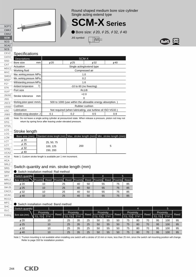
244
Round shaped medium bore size cylinderSingle acting extend type
SCM-X Series Bore size: 20, 25, 32, 40
JIS symbol
Specifications
Bore size
Actuation
Working fluid
Max. working pressure
Min. working pressure
Withstanding pressure
Ambient temperature
Port size
Stroke tolerance
Working piston speed
Cushion
Lubrication
Allowable energy absorption
20
0.1
25
0.2
32
0.5
SCM-X 40
0.9
mm
MPa
MPa
MPa
mm
mm/s
J
Single acting/extend type
Compressed air
1.0
0.2
1.6
-10 to 60 (no freezing)
Rc1/8
+2.0
0
500 to 1000 (use within the allowable energy absorption. )
Rubber cushion
Not required (when lubricating, use turbine oil ISO VG32.)
Stroke length
Descriptions
Note: Do not leave a single acting cylinder at pressurized state. When release a pressure, piston rod may not return by spring force after leaving under elevated pressure.
200 5
Standard stroke length (mm) Max. stroke length (mm) Min. stroke length (mm)Bore size (mm)
25, 50, 75
100, 125
150, 200
20
25
32
40
Note 1: Custom stroke length is available per 1 mm increment.
Proximity Reed
Switch quantity
Bore size (mm)
1
10
10
10
10
Proximity Reed Proximity Reed
2 3
25
25
25
25
Proximity Reed
4
55
55
55
55
40
40
40
40
50
50
50
50
Proximity Reed
5
75
75
75
75
85
85
85
85
Switch quantity and min. stroke length (mm) Switch installation method: Rail method
Proximity
T2, T3 T*Y*Reed
Switch quantity
Bore size (mm)
1
Proximity
T2, T3 T*Y*Reed
2
20
25
32
40
20
25
32
40
10
10
10
10
25
25
25
25
35
35
35
35
25
25
25
25
Switch installation method: Band method
Proximity
T2, T3 T*Y*Reed
3
50
50
50
50
55
55
55
55
50
50
50
50
Proximity
T2, T3 T*Y*Reed
4
75
75
75
75
80
80
80
80
70
70
70
70
Proximity
T2, T3 T*Y*Reed
5
95
95
95
95
100
100
100
100
95
95
95
95
Note 1: Trunion mounting is not available when installing one switch with a stroke of 10 mm or more, less than 25 mm, since the switch rail mounting position will change. Refer to page 333 for installation position.
SCP*2
CMK2
CMA2
SCM
SCG
SCA2
SCS
CKV2
CA/OV2
SSD
CAT
MDC2
MVC
SMD2
MSD*
FC*
STK
ULK*
JSK/M2
JSG
JSC3
USSD
USC
JSB3
LMB
STG
STS/L
LCS
LCG
LCM
LCT
LCY
STR2
UCA2
HCM
HCA
SRL2
SRG
SRM
SRT
MRL2
MRG2
SM-25
CAC3
UCAC
RCC2
MFC
SHC
GLC
Ending

245
SCP*2
CMK2
CMA2
SCM
SCG
SCA2
SCS
CKV2
CA/OV2
SSD
CAT
MDC2
MVC
SMD2
MSD*
FC*
STK
ULK*
JSK/M2
JSG
JSC3
USSD
USC
JSB3
LMB
STG
STS/L
LCS
LCG
LCM
LCT
LCY
STR2
UCA2
HCM
HCA
SRL2
SRG
SRM
SRT
MRL2
MRG2
SM-25
CAC3
UCAC
RCC2
MFC
SHC
GLC
Ending
Rou
nd s
hape
d cy
linde
rS
tand
ard
type
SCM-X Series
Specifications
Spring loadStroke length 0 mm Full stroke length during operationBore size (mm)
20
25
32
40
(Unit: N)
(Unit: kg)
(Unit: kg)
(Unit: kg)
(Unit: kg)
11.8
12.5
24.3
28.4
38
40.2
54.9
100
Cylinder weight (stroke length: 5 to 50)
Basic type
Descriptions/mounting style
Port size
Product weight when stroke length (S) = 0 mm Switch weight
0.15
0.24
0.36
0.59
Axial foot type
0.26
0.37
0.52
0.81
Flange type
0.18
0.28
0.42
0.67
Clevis type
0.20
0.32
0.51
0.82
Trunnion type
0.16
0.26
0.39
0.64
Grommet
0.018
0.018
0.018
0.018
Additional weightper S = 10 mm
0.010
0.014
0.018
0.030
0.012
0.016
0.020
0.032
0.007
0.007
0.007
0.007
Additional weightper S = 10 mm
(with rail)
Band weightper 1 switch
Cylinder weight (stroke length: 51 to 100)
Basic type
Descriptions/mounting style
Port size
Product weight when stroke length (S) = 0 mm Switch weight
0.19
0.32
0.46
0.76
Axial foot type
0.30
0.45
0.62
0.98
Flange type
0.22
0.36
0.52
0.84
Clevis type
0.24
0.40
0.61
0.99
Trunnion type
0.20
0.34
0.49
0.81
Grommet
0.018
0.018
0.018
0.018
0.010
0.014
0.018
0.030
0.012
0.016
0.020
0.032
0.007
0.007
0.007
0.007
Cylinder weight (stroke length: 101 to 150)
Basic type
Descriptions/mounting style
Port size
Product weight when stroke length (S) = 0 mm Switch weight
0.24
0.39
0.55
0.94
Axial foot type
0.35
0.52
0.71
1.16
Flange type
0.27
0.43
0.61
1.02
Clevis type
0.29
0.47
0.70
1.17
Trunnion type
0.25
0.41
0.58
0.99
Grommet
0.018
0.018
0.018
0.018
0.010
0.014
0.018
0.030
0.012
0.016
0.020
0.032
0.007
0.007
0.007
0.007
Cylinder weight (stroke length: 151 to 200)
Basic type
Descriptions/mounting style
Port size
Product weight when stroke length (S) = 0 mm Switch weight
20
25
32
40
20
25
32
40
20
25
32
40
20
25
32
40
0.29
0.46
0.65
1.11
Axial foot type
0.40
0.59
0.81
1.33
Flange type
0.32
0.50
0.71
1.19
Clevis type
0.34
0.54
0.80
1.34
Trunnion type
0.30
0.48
0.68
1.16
Grommet
0.018
0.018
0.018
0.018
0.010
0.014
0.018
0.030
0.012
0.016
0.020
0.032
0.007
0.007
0.007
0.007
(E.g.) Product weight of SCM-X-LB-40D-100-T2H-D
Product weight when S = 0 mm 0.98 kg
Additional weight when S = 100 mm 0.032 x 100 =0.32 kg
Weight of 2 switches 0.036 kg
Product weight 0.98 kg + 0.32 kg + 0.036 kg = 1.336 kg
10
Switch specifications
Descriptions
Applications
Output method
Power voltage
Load voltage
Load current
Light
Leakage current
Programmable controller,
relay, small solenoid valve
85 to 265 VAC
5 to 100 mA
LED
(ON lighting)
1 mA or less with 100 VAC
2 mA or less with 200 VAC
Programmable
controller dedicated
10 to 30 VDC
5 to 20 mA (Note 1)
1 mA or less
-
-
10 A or less 0 mA
With preventive maintenance output
1 color/2 color indicator
Descriptions
Applications
Output method
Programmable
controller dedicated
-
10 to 30 VDC
5 to 20 mA
1 mA or less
20 mA or less
Programmable
controller dedicated
-
10 to 30 VDC
5 to 20 mA
1.2 mA or less
5 to 20 mA or less
Programmable
controller, relay
10 to 28 VDC
30 VDC or less
50 mA or less
10 A or less
50 mA or less
Programmable
controller, relay
10 to 28 VDC
30 VDC or less
50 mA or less
10 A or less
50 mA or less
T2YFH/V T3YFH/V T2YMH/V T3YMH/V
Red/Green LED (ON lighting)
NPN output
30 VDC or less
10 A or less
Yellow LED (ON lighting)-Installation position adjustment
Preventive maintenance output
Power voltage
Load voltage
Load current
Leakage current
Load voltage
Load current
Leakage current
Reg
ular
outp
ut
Prev
entiv
ema
inten
ance
outp
utLi
ght
Proximity 3-wire Proximity 4-wire Proximity 3-wire Proximity 4-wire
Reed 2-wireProximity 3-wireProximity 2-wire
T1H/T1VT2H/T2V/
T2JH/T2JV
T2YH/
T2YVT3H/T3V
T3PH/T3PV
(Custom order)
T3YH/
T3YV
NPN output PNP output
10 to 28 VDC
30 VDC or less
100 mA or less
NPN output
50 mA or less
T0H/T0V T5H/T5V T8H/T8V
Red/GreenLED
(ON lighting)
Programmable
controller, relay
Programmable
controller, relay
Programmable controller,
relay
Programmable controller,relay, IC circuit (w/o light),
serial connection
12/24 VDC
5 to 50 mA
110 VAC
7 to 20 mA
LED
(ON lighting)
5/12/24 VDC
50 mA or less
110 VAC
20 mA or less
without light
12/24 VDC
5 to 50 mA
220 VAC
7 to 10 mA
110 VAC
7 to 20 mA
LED
(ON lighting)
LED
(ON lighting)
GreenLED
(ON lighting)
Red/greenLED
(ON lighting)
LED
(ON lighting)
-
-
Note 1: Refer to Ending 1 for other switch specifications.Note 2: Max. load current above: 20 mA at 25 . The current will be lower than 20 mA if ambient temperature around switch is higher than 25 . (5 to 10mA at 60 )
* The T0/T5 switch can be used with 220 VAC. Contact CKD for working conditions.
Additional weightper S = 10 mm
Additional weightper S = 10 mm
(with rail)
Band weightper 1 switch
Additional weightper S = 10 mm
Additional weightper S = 10 mm
(with rail)
Band weightper 1 switch
Additional weightper S = 10 mm
Additional weightper S = 10 mm
(with rail)
Band weightper 1 switch

246
A
How to orderWithout switch
With switch
Mounting styleNote 1
I OptionNote 4, Note 6
J AccessoryNote 7
H Switch installation method
<Example of model number>
SCM-X-LB-40D-100-T0H-D-JIModel: Round shaped cylinder single acting extend type
Mounting style : Axial foot typeBore size : 40 mmPort thread type : Rc threadCushion : Both sides rubber cushionedStroke length : 100 mmSwitch model no. : Proximity T0H switch, lead wire 1 mSwitch quantity : 2Switch installation method : Rail methodOption : Bellows material/max. ambient temperature 60Accessory : Rod eye
A
B
C
D
E
F
G
H
I
J
LB JDD IT0H40SCM-X 100
LB JD I40SCM-X 100
Note on model no. selection
G Switch quantityNote 4
F Switch model no.Note 3
E Stroke length
D Cushion
C Port thread type
B Bore size
Note 1: The mounting bracket is shipped with the product.Note 2: Refer to page 244 for switch quantity and min. stroke length.Note 3: Switches other than switch model no. "F" are available.
(Custom order)Refer to Ending 1 for details.
Note 4: The instantaneous maximum temperature is that at which sparks, swarf, etc., temporarily contact bellows.
Note 5: Refer to Ending 89 about custom specifications of rod end form.Note 6: When the switch mounting type "Z" is selected, the switch rail
enclosed shipment "Q" cannot be selected.Note 7: "I" and "Y" can not be selected at the same time.
Symbol Descriptions
00LBFAFBCATATB
Mounting styleA
Bore size (mm)B
CushionD
Stroke length (mm)E
Basic typeAxial foot typeRod end flange typeHead end flange typeEye bracket typeRod end trunnion typeHead end trunnion type
Bore size 20 to 40
Stroke length Note 2 Custom stroke length5 to 200 Per 1 mm
20253240
20253240
Port thread typeC
BlankNG
Rc threadNPT thread (custom order)G thread (custom order)
D Both sides rubber cushioned
Switch quantityG
RHDT4
One on rod endOne on head endTwoThree4 switches (When more than 4 switches, indicate switch quantity.)
Switch installation methodH
BlankZ
Rail methodBand method
OptionI
Max. ambient60
100 250
Max. instantaneous100 200 400
JKLQMP6
Bellows materialBellows materialBellows materialSwitch rail attached at shipmentPiston rod material (stainless steel)Copper and PTFE free
AccessoryJ
IY
B2
Rod eyeRod clevis (pin and snap ring attached)Clevis bracket
Indicator
1 color indicator typewithout light
1 color indicator type
1 colorindicator type
1 color indicator type (custom order)2 color
indicator type
Off-delay type
Conta
ctR
eed
Pro
xim
ity
Leadwire
2-wire
2-wire
3-wire
2-wire3-wire3-wire4-wire3-wire4-wire
2-wire
2-wire
Axial leadwireT0H*T5H*T8H*T1H*T2H*T3H*
T3PH*T2YH*T3YH*
T2YFH*T3YFH*T2YMH*T3YMH*T2YD*
T2YDT*T2JH*
Radial leadwireT0V*T5V*T8V*T1V*T2V*T3V*
T3PV*T2YV*T3YV*
T2YFV*T3YFV*T2YMV*T3YMV*
--
T2JV*
Strong magneticfield proof switch
2 color indicator type(W/o light for preventive
maintenance output)
2 color indicator type(W/ light for preventive
maintenance output (1 color))
Blank35
1 m (standard)3 m (option)5 m (option)
Switch model no.F
*Lead wire length
SCM-X Series
SCP*2
CMK2
CMA2
SCM
SCG
SCA2
SCS
CKV2
CA/OV2
SSD
CAT
MDC2
MVC
SMD2
MSD*
FC*
STK
ULK*
JSK/M2
JSG
JSC3
USSD
USC
JSB3
LMB
STG
STS/L
LCS
LCG
LCM
LCT
LCY
STR2
UCA2
HCM
HCA
SRL2
SRG
SRM
SRT
MRL2
MRG2
SM-25
CAC3
UCAC
RCC2
MFC
SHC
GLC
Ending

247
SCP*2
CMK2
CMA2
SCM
SCG
SCA2
SCS
CKV2
CA/OV2
SSD
CAT
MDC2
MVC
SMD2
MSD*
FC*
STK
ULK*
JSK/M2
JSG
JSC3
USSD
USC
JSB3
LMB
STG
STS/L
LCS
LCG
LCM
LCT
LCY
STR2
UCA2
HCM
HCA
SRL2
SRG
SRM
SRT
MRL2
MRG2
SM-25
CAC3
UCAC
RCC2
MFC
SHC
GLC
Ending
Rou
nd s
hape
d cy
linde
rS
tand
ard
type
Switch model no.(Item previous page)
Switch body + mounting rail set
SCM T0H D 40
F B
B
G EE
Bore size(Item
previous page)
Switch quantity(Item previous page)
Stroke length (Note 1)(Item previous page)
T0HSW
100
Only mounting rail
SCM T 40
Bore size(Item previous page)
Mounting rail
(Note 2)Stroke length (Note 1)
(Item previous page)
100
(switch installation method: rail method)
How to order switch
Switch model no.(Item previous page)
Switch body + mounting rail + band
SCM T2H* 40
F
B
Bore size(Item previous page)
Z
(switch installation method: band method)
(only switch body)
Mounting rail + band
SCM 40
B
Bore size(Item previous page)
Z
F
Switch model no.(Item previous page)
How to order mounting bracket
20Bore size (mm)
Mounting bracketFoot (LB)
Flange (FA/FB)
Eye (CA)
Trunnion (TA/TB)
SCM-LB-20
SCM-FA-20
SCM-CA-20
SCM-TA-20
25
SCM-LB-25
SCM-FA-25
SCM-CA-25
SCM-TA-25
32
SCM-LB-32
SCM-FA-32
SCM-CA-32
SCM-TA-32
40
SCM-LB-40
SCM-FA-40
SCM-CA-40
SCM-TA-40
Note 1: Mounting bolts are attached to each mounting bracket.Note 2: 2 piece/set is applied for a foot type mounting bracket.
Note 1: When more than 300 mm stroke, indicate "X".When more than 300 mm stroke, a short rail(100 mm switch adjustment distance) is provided per switch.
Note 2: When X is indicated only with the mounting rail,order the same number of rails as the number of switches being used.
SCM-X Series
How to order

248
Spring holder A
Coil spring
Spring holder B
Aluminum alloy
Piano wire
Aluminum alloy
Internal structure and parts list
1
2
3
No. Parts name Material Remarks
Electrode position coating
Repair parts listConsumables part numbers follow the SCM series internal structure drawing (page 228).
Bore size (mm)
20
25
32
40
SCM-X-20DK
SCM-X-25DK
SCM-X-32DK
SCM-X-40DK
Kit No. Repair parts number
3 6 8 10 13
21 3
SCM-X Series
SCP*2
CMK2
CMA2
SCM
SCG
SCA2
SCS
CKV2
CA/OV2
SSD
CAT
MDC2
MVC
SMD2
MSD*
FC*
STK
ULK*
JSK/M2
JSG
JSC3
USSD
USC
JSB3
LMB
STG
STS/L
LCS
LCG
LCM
LCT
LCY
STR2
UCA2
HCM
HCA
SRL2
SRG
SRM
SRT
MRL2
MRG2
SM-25
CAC3
UCAC
RCC2
MFC
SHC
GLC
Ending

249
SCP*2
CMK2
CMA2
SCM
SCG
SCA2
SCS
CKV2
CA/OV2
SSD
CAT
MDC2
MVC
SMD2
MSD*
FC*
STK
ULK*
JSK/M2
JSG
JSC3
USSD
USC
JSB3
LMB
STG
STS/L
LCS
LCG
LCM
LCT
LCY
STR2
UCA2
HCM
HCA
SRL2
SRG
SRM
SRT
MRL2
MRG2
SM-25
CAC3
UCAC
RCC2
MFC
SHC
GLC
Ending
Rou
nd s
hape
d cy
linde
rS
tand
ard
type
Single acting extend type
20, 25
20
25
32
40
Symbol
30
35
31.5
40
b
35
40
40
50
XF
214
231
233
250
187
201
203
220
30
30
35
35
d
25.7
30.7
37.7
46.7
(stroke length/3) + 18.5
(stroke length/3) + 20.5
(stroke length/3) + 19
(stroke length/3) + 18.5
s
14
16.5
20
26
SD
5
6
6
8
T
X
17
18
18
20
WF
133
141
143
160
160
171
173
190
With bellows Switch installation method: rail method
51to
100
5to
50st
101to
150
151to
200
RD
19.5
22
25.5
30
P
23
24.4
25
25.7
GB
18.5
18.5
18.5
20.5
GN
30
30
32
36
GL
4
3
4
6
7
6
7
9
T0,T5
T2,T3
33.5
37.5
38.5
40.5
60.5
67.5
68.5
70.5
87.5
97.5
98.5
100.5
114.5
127.5
128.5
130.5
T0, T55 to50
50 to100
100 to150
150 to200
HD
Bore size (mm)
Dimensions
Note 1: Refer to the page 333 for the RD, HD, and projecting dimensions of the 2-color indication type, preventive maintenance output type, off delay type, strong magnetic field proof type, T1H/V, T8H/V switch.Note 2: Refer to page 334 and 335 for accessory dimensions.
· Switch installation method: rail method
· Switch installation method: band method
10
10
10
12
QB
20
25
32
40
Symbol
Bore size (mm)M8
M10 x 1.25
M10 x 1.25
M14 x 1.5
KK
12
14
18
25
J
96
99
101
108
6
8
10
14
MN
4
5
5.5
6
MO
123
129
131
138
51 - 1005 - 50st
150
159
161
168
101 - 150
177
189
191
198
151 - 200
11
11
11
12
LL
11
11
10
10
MBMA
24
29
36
44
M5
M6
M8
M10
MC MD
8
10
12
16
MM
12
12
12
13
QA
18
22
22
30
A
15.5
19.5
19.5
27
C D
M4 depth 6.5
M5 depth 6.5
M5 depth 7.5
M6 depth 12
DA
Rc1/8
Rc1/8
Rc1/8
Rc1/8
EE
Basic type (00) basic dimensions
26
31
38
47
13
17
17
22
B
19
19
19
20
GR
17
17
17
19
GH
5.5
4.5
5.5
7.5
6.5
5.5
6.5
8.5
33.5
37.5
38.5
40.5
RDHDGD
T2, 3
RD
1.5
0.5
1.5
3.5
2.5
1.5
2.5
4.5
Switch installation method: band method
20
25
32
40
Note: Each mounting style installation dimension is same as SCM (double acting). Refer to pages 232 to 243.
T0,T5
T0, T5T2,T3
34.5
38.5
39.5
41.5
150 to200
5 to50
60.5
67.5
68.5
70.5
50 to100
87.5
97.5
98.5
100.5
100 to150
114.5
127.5
128.5
130.5
150 to200
Symbol
Bore size (mm)
61.5
68.5
69.5
71.5
88.5
98.5
99.5
101.5
115.5
128.5
129.5
131.5
5 to50
50 to100
100 to150
GL
30.5
29.5
30.5
32.5
29.5
28.5
29.5
31.5
T0,T5
T2,T3
T0,T5
T2,T3
34.5
38.5
39.5
41.5
T2, T35 to50
61.5
68.5
69.5
71.5
50 to100
88.5
98.5
99.5
101.5
100 to150
115.5
128.5
129.5
131.5
150 to200
19.6
22.1
25.6
30.2
P1
21.5
23.9
27.6
32.1
P2
(38°)
(34°)
(30°)
(26°)
P
MN (width across flats)
Width across flats B
MM MM
J JDds
MO
SD
SD
8-DA
MC
GB
18
A
CC 2 GN
QBQAT
RD HD
2-EE
2KKKK
XF MA 4-MDMO
WF
A 2WFA
b
WF +
XF +
X + + stroke lengthX + stroke length
LL + stroke lengthGL + stroke length
P
(with bellows)
(P )
P1
7.9
P2
ba
GR RD
GL + stroke length
10
HD30.5
GH30.5
10
ba
GD
GR GH
MB
SCM-X Series
Single acting extend type

250
Round shaped medium bore size cylinderSingle acting retract type
SCM-Y Series Bore size: 20, 25, 32, 40
JIS symbol
Specifications
Bore size
Actuation
Working fluid
Max. working pressure
Min. working pressure
Withstanding pressure
Ambient temperature
Port size
Stroke tolerance
Working piston speed
Cushion
Lubrication
Allowable energy absorption
20
0.1
25
0.2
32
0.5
SCM-Y 40
0.9
mm
MPa
MPa
MPa
mm
mm/s
J
Single acting/retract type
Compressed air
1.0
0.2
1.6
-10 to 60 (no freezing)
Rc1/8
+2.0
0
500 to 1000 (use within the allowable energy absorption. )
Rubber cushion
Not required (when lubricating, use turbine oil ISO VG32.)
Stroke length
Descriptions
Note: Do not leave a single acting cylinder at pressurized state. When release a pressure, piston rod may not return by spring force after leaving under elevated pressure.
200 5
Standard stroke length (mm) Max. stroke length (mm) Min. stroke length (mm)Bore size (mm)
25, 50, 75,
100, 125,
150, 200
20
25
32
40
Note 1: Custom stroke length is available per 1 mm increment.
Proximity Reed
Switch quantity
Bore size (mm)
1
20
25
32
40
10
10
10
10
Proximity Reed Proximity Reed
2 3
25
25
25
25
Proximity Reed
4
55
55
55
55
40
40
40
40
50
50
50
50
Proximity Reed
5
75
75
75
75
85
85
85
85
Switch quantity and min. stroke length (mm) Switch installation method: Rail method
Proximity
T2, T3 T*Y*Reed
Switch quantity
Bore size (mm)
1
Proximity
T2, T3 T*Y*Reed
2
20
25
32
40
10
10
10
10
25
25
25
25
35
35
35
35
25
25
25
25
Switch installation method: Band method
Proximity
T2, T3 T*Y*Reed
3
50
50
50
50
55
55
55
55
50
50
50
50
Proximity
T2, T3 T*Y*Reed
4
75
75
75
75
80
80
80
80
70
70
70
70
Proximity
T2, T3 T*Y*Reed
5
95
95
95
95
100
100
100
100
95
95
95
95
Note 1: Trunion mounting is not available when installing one switch with a stroke of 10 mm or more, less than 25 mm, since the switch rail mounting position will change.Refer to page 333 for installation position.
SCP*2
CMK2
CMA2
SCM
SCG
SCA2
SCS
CKV2
CA/OV2
SSD
CAT
MDC2
MVC
SMD2
MSD*
FC*
STK
ULK*
JSK/M2
JSG
JSC3
USSD
USC
JSB3
LMB
STG
STS/L
LCS
LCG
LCM
LCT
LCY
STR2
UCA2
HCM
HCA
SRL2
SRG
SRM
SRT
MRL2
MRG2
SM-25
CAC3
UCAC
RCC2
MFC
SHC
GLC
Ending

251
SCP*2
CMK2
CMA2
SCM
SCG
SCA2
SCS
CKV2
CA/OV2
SSD
CAT
MDC2
MVC
SMD2
MSD*
FC*
STK
ULK*
JSK/M2
JSG
JSC3
USSD
USC
JSB3
LMB
STG
STS/L
LCS
LCG
LCM
LCT
LCY
STR2
UCA2
HCM
HCA
SRL2
SRG
SRM
SRT
MRL2
MRG2
SM-25
CAC3
UCAC
RCC2
MFC
SHC
GLC
Ending
Rou
nd s
hape
d cy
linde
rS
tand
ard
type
SCM-Y Series
Specifications
Spring loadStroke length 0 Full stroke length during operationBore size (mm)
20
25
32
40
(Unit: N)
11.8
12.5
24.3
28.4
38
40.2
54.9
100
Cylinder weight (stroke length: 5 to 50)
Basic type
Descriptions/mounting style
Port size
Product weight when stroke length (S) = 0 mm Switch weight
0.14
0.22
0.33
0.54
Axial foot type
0.25
0.35
0.49
0.76
Flange type
0.17
0.26
0.39
0.62
Clevis type
0.19
0.30
0.48
0.77
Trunnion type
0.15
0.24
0.36
0.59
Grommet
0.018
0.018
0.018
0.018
Additional weightper S = 10 mm
0.010
0.014
0.018
0.030
0.012
0.016
0.020
0.032
0.007
0.007
0.007
0.007
Additional weightper S = 10 mm
(with rail)
Band weight per 1 switch
Cylinder weight (stroke length: 51 to 100)
Basic type
Descriptions/mounting style
Port size
Switch weight
0.17
0.28
0.40
0.67
Axial foot type
0.28
0.41
0.56
0.89
Flange type
0.20
0.32
0.46
0.75
Clevis type
0.22
0.36
0.55
0.90
Trunnion type
0.18
0.30
0.43
0.72
Grommet
0.018
0.018
0.018
0.018
Additional weightper S = 10 mm
0.010
0.014
0.018
0.030
0.012
0.016
0.020
0.032
0.007
0.007
0.007
0.007
Additional weightper S = 10 mm
(with rail)
Band weight per 1 switch
Cylinder weight (stroke length: 101 to 150)
Basic type
Descriptions/mounting style
Port size
Switch weight
0.21
0.33
0.47
0.80
Axial foot type
0.32
0.46
0.63
1.02
Flange type
0.24
0.37
0.53
0.88
Clevis type
0.26
0.41
0.62
1.03
Trunnion type
0.22
0.35
0.50
0.85
Grommet
0.018
0.018
0.018
0.018
Additional weightper S = 10 mm
0.010
0.014
0.018
0.030
0.012
0.016
0.020
0.032
0.007
0.007
0.007
0.007
Additional weightper S = 10 mm
(with rail)
Band weight per 1 switch
Cylinder weight (stroke length: 151 to 200)
Basic type
Descriptions/mounting style
Port size
Switch weight
20
25
32
40
20
25
32
40
20
25
32
40
20
25
32
40
0.24
0.39
0.54
0.92
Axial foot type
0.35
0.52
0.70
1.14
Flange type
0.27
0.43
0.60
1.00
Clevis type
0.29
0.47
0.69
1.15
Trunnion type
0.25
0.41
0.57
0.97
Grommet
0.018
0.018
0.018
0.018
Additional weightper S = 10 mm
0.010
0.014
0.018
0.030
0.012
0.016
0.020
0.032
0.007
0.007
0.007
0.007
Additional weightper S = 10 mm
(with rail)
Band weight per 1 switch
(Eg.) Product weight of SCM-Y-LB-40D-100-T2H-D
Product weight when S = 0 mm 0.89 kg
Additional weight when S = 100 mm 0.032 x 100 = 0.32 kg
Weight of 2 switches 0.036 kg
Product weight 0.89 kg + 0.32kg + 0.036 kg = 1.246 kg
10
Product weight when stroke length (S) = 0 mm
Product weight when stroke length (S) = 0 mm
Product weight when stroke length (S) = 0 mm
Switch specifications
Descriptions
Applications
Output method
Power voltage
Load voltage
Load current
Light
Leakage current
Programmable controller,
relay, small solenoid valve
85 to 265 VAC
5 to 100 mA
LED
(ON lighting)
1 mA or less with 100 VAC
2 mA or less with 200 VAC
Programmable
controller dedicated
10 to 30 VDC
5 to 20 mA (Note 1)
1 mA or less
-
-
10 A or less 0 mA
With preventive maintenance output
1 color/2 color indicator
Descriptions
Applications
Output method
Programmable
controller dedicated
-
10 to 30 VDC
5 to 20 mA
1 mA or less
20 mA or less
Programmable
controller dedicated
-
10 to 30 VDC
5 to 20 mA
1.2 mA or less
5 to 20 mA or less
Programmable
controller, relay
10 to 28 VDC
30 VDC or less
50 mA or less
10 A or less
50 mA or less
Programmable
controller, relay
10 to 28 VDC
30 VDC or less
50 mA or less
10 A or less
50 mA or less
T2YFH/V T3YFH/V T2YMH/V T3YMH/V
Red/Green LED (ON lighting)
NPN output
30 VDC or less
10 A or less
Yellow LED (ON lighting)-Installation position adjustment
Preventive maintenance output
Power voltage
Load voltage
Load current
Leakage current
Load voltage
Load current
Leakage current
Reg
ular
outp
ut
Prev
entiv
ema
inten
ance
outp
utLi
ght
Proximity 3-wire Proximity 4-wire Proximity 3-wire Proximity 4-wire
Reed 2-wireProximity 2-wire Proximity 3-wire
T1H/T1VT2H/T2V/
T2JH/T2JV
T2YH/
T2YV
T3H/
T3V
T3PH/T3PV
(Custom order)
T3YH/
T3YV
NPN output PNP output
10 to 28 VDC
30 VDC or less
100 mA or less
NPN output
50 mA or less
T0H/T0V T5H/T5V T8H/T8V
Red/GreenLED
(ON lighting)
Programmable
controller, relay
Programmable
controller, relay
Programmable controller,
relay
Programmable controller,relay, IC circuit (w/o light),
serial connection
12/24 VDC
5 to 50 mA
110 VAC
7 to 20 mA
LED
(ON lighting)
5/12/24 VDC
50 mA or less
110 VAC
20 mA or less
without light
12/24 VDC
5 to 50 mA
220 VAC
7 to 10 mA
110 VAC
7 to 20 mA
LED
(ON lighting)
LED
(ON lighting)
GreenLED
(ON lighting)
Red/greenLED
(ON lighting)
LED
(ON lighting)
-
-
Note 1: Refer to Ending 1 for other switch specifications.Note 2: Max. load current above: 20 mA at 25 . The current will be lower than 20 mA if ambient temperature around switch is higher than 25 . (5 to 10mA at 60 )
* The T0/T5 switch can be used with 220 VAC. Contact CKD for working conditions.
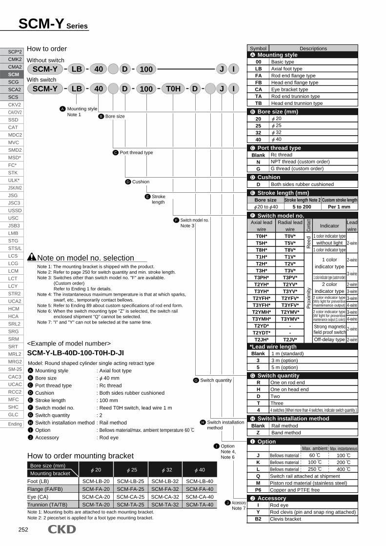
252
SCM-Y Series
A
How to order
Without switch
With switch
Mounting styleNote 1
I OptionNote 4, Note 6
J AccessoryNote 7
<Example of model number>
SCM-Y-LB-40D-100-T0H-D-JIModel: Round shaped cylinder single acting retract type
Mounting style : Axial foot type
Bore size : 40 mm
Port thread type : Rc thread
Cushion : Both sides rubber cushioned
Stroke length : 100 mm
Switch model no. : Reed T0H switch, lead wire 1 m
Switch quantity : 2
Switch installation method : Rail method
Option : Bellows material/max. ambient temperature 60
Accessory : Rod eye
A
B
C
D
E
F
G
H
I
J
LB JDD IT0H40SCM-Y 100
LB JD I40SCM-Y 100
How to order mounting bracket
Foot (LB)
Flange (FA/FB)
Eye (CA)
Trunnion (TA/TB)
20Bore size (mm)
Mounting bracket
SCM-LB-20
SCM-FA-20
SCM-CA-20
SCM-TA-20
SCM-LB-25
SCM-FA-25
SCM-CA-25
SCM-TA-25
SCM-LB-32
SCM-FA-32
SCM-CA-32
SCM-TA-32
SCM-LB-40
SCM-FA-40
SCM-CA-40
SCM-TA-40
25 32 40
Note 1: Mounting bolts are attached to each mounting bracket.Note 2: 2 piece/set is applied for a foot type mounting bracket.
Note on model no. selection
H Switch installationmethod
G Switch quantity
F Switch model no.Note 3
E Stroke length
D Cushion
C Port thread type
B Bore size
Note 1: The mounting bracket is shipped with the product.Note 2: Refer to page 250 for switch quantity and min. stroke length.Note 3: Switches other than switch model no. "F" are available.
(Custom order)Refer to Ending 1 for details.
Note 4: The instantaneous maximum temperature is that at which sparks, swarf, etc., temporarily contact bellows.
Note 5: Refer to Ending 89 about custom specifications of rod end form.Note 6: When the switch mounting type "Z" is selected, the switch rail
enclosed shipment "Q" cannot be selected.Note 7: "I" and "Y" can not be selected at the same time.
Symbol DescriptionsMounting styleA
Bore size (mm)B
CushionD
Stroke length (mm)E
Bore size Stroke length Note 2 20 to 40 5 to 200
Custom stroke lengthPer 1 mm
00LBFAFBCATATB
Basic typeAxial foot typeRod end flange typeHead end flange typeEye bracket typeRod end trunnion typeHead end trunnion type
20253240
20253240
Port thread typeC
BlankNG
Rc threadNPT thread (custom order)G thread (custom order)
D Both sides rubber cushioned
Switch quantityG
JKLQMP6
IY
B2
OptionI
AccessoryJ
Bellows materialBellows materialBellows materialSwitch rail attached at shipmentPiston rod material (stainless steel)Copper and PTFE free
Rod eyeRod clevis (pin and snap ring attached)Clevis bracket
Switch installation methodH
Max. ambient60 100 250
Max. instantaneous100 200 400
BlankZ
Rail methodBand method
RHDT4
One on rod endOne on head endTwoThree4 switches (When more than 4 switches, indicate switch quantity.)
Switch model no.F
*Lead wire length
Indicator
1 color indicator typewithout light
1 color indicator type
1 colorindicator type
1 color indicator type (custom order)2 color
indicator type
Off-delay type
Conta
ctR
eed
Pro
xim
ity
Leadwire
2-wire
2-wire
3-wire
2-wire3-wire3-wire4-wire3-wire4-wire
2-wire
2-wire
Axial leadwireT0H*T5H*T8H*T1H*T2H*T3H*
T3PH*T2YH*T3YH*
T2YFH*T3YFH*T2YMH*T3YMH*T2YD*
T2YDT*T2JH*
Radial leadwireT0V*T5V*T8V*T1V*T2V*T3V*
T3PV*T2YV*T3YV*
T2YFV*T3YFV*T2YMV*T3YMV*
--
T2JV*
Strong magneticfield proof switch
Blank35
1 m (standard)3 m (option)5 m (option)
2 color indicator type(W/o light for preventivemaintenance output)
2 color indicator type(W/ light for preventivemaintenance output (1 color))
SCP*2
CMK2
CMA2
SCM
SCG
SCA2
SCS
CKV2
CA/OV2
SSD
CAT
MDC2
MVC
SMD2
MSD*
FC*
STK
ULK*
JSK/M2
JSG
JSC3
USSD
USC
JSB3
LMB
STG
STS/L
LCS
LCG
LCM
LCT
LCY
STR2
UCA2
HCM
HCA
SRL2
SRG
SRM
SRT
MRL2
MRG2
SM-25
CAC3
UCAC
RCC2
MFC
SHC
GLC
Ending

253
SCP*2
CMK2
CMA2
SCM
SCG
SCA2
SCS
CKV2
CA/OV2
SSD
CAT
MDC2
MVC
SMD2
MSD*
FC*
STK
ULK*
JSK/M2
JSG
JSC3
USSD
USC
JSB3
LMB
STG
STS/L
LCS
LCG
LCM
LCT
LCY
STR2
UCA2
HCM
HCA
SRL2
SRG
SRM
SRT
MRL2
MRG2
SM-25
CAC3
UCAC
RCC2
MFC
SHC
GLC
Ending
Rou
nd s
hape
d cy
linde
rS
tand
ard
type
Spring holder A
Coil spring
Spring holder B
Aluminum alloy
Piano wire
Aluminum alloy
Mounting rail
Internal structure and parts list
1
2
3
No. Parts name Material Remarks
Electrode position coating
Switch model no.(Item previous page)
Switch body + mounting rail set
SCM T0H D 40
F B
B
G EE
Bore size(Item
previous page)
Switch quantity(Item previous page)
Stroke length (Note 1)(Item previous page)
T0HSW
100
Only mounting rail
SCM T 40
Bore size(Item previous page)
Stroke length(Item previous page)
100
(switch installation method: rail method)
How to order switch
Switch model no.(Item previous page)
Switch body + mounting rail + band
SCM T2H* 40
F
B
Bore size(Item previous page)
Z
(switch installation method: band method)
(only switch body)
Mounting rail + band
SCM 40
B
Bore size(Item previous page)
Z
F
Switch model no.(Item previous page)
(Note 1)(Note 2)
Repair parts listConsumables part numbers follow the SCM series internal structure drawing (page 228).
Bore size (mm)
20
25
32
40
SCM-Y-20DK
SCM-Y-25DK
SCM-Y-32DK
SCM-Y-40DK
Kit No. Repair parts number
3 6 8 10 13
Note 1: When more than 300 mm stroke, indicate "X". When more than 300 mm stroke, a short rail (100 mm switch adjustment distance) is provided per switch.Note 2: When X is indicated only with the mounting rail, order the same number of rails as the number of switches being used.
21 3
SCM-Y Series
How to order / Internal structure

254
SCM-Y Series
Single acting retract type (00)
T0,T5
T0, T5T0,T5
T2,T3
T0, T5 T2, T3T2,T3
GC GL
20
25
32
40
61
66
67
69
88
96
97
99
115
126
127
129
2.5
3.5
4.5
6.5
3.5
4.5
5.5
7.5
31.5
32.5
33.5
35.5
32.5
34.5
35.5
37.5
59.5
64.5
65.5
67.5
86.5
94.5
95.5
97.5
113.5
124.5
125.5
127.5
30.5
31.5
32.5
34.5
RDHDHD
T0, T5 T2, T3
Switch installation method: rail method Switch installation method: band methodSymbol
Bore size (mm)50 to100
100 to150
150 to200
5 to50
50 to100
100 to150
150 to200
34
36
37
39
31
33
34
36
58
63
64
66
85
93
94
96
112
123
124
126
5 to50
5 to50
50 to100
100 to150
150 to200
T2, T3
33.5
35.5
36.5
38.5
60.5
65.5
66.5
68.5
87.5
95.5
96.5
98.5
114.5
125.5
126.5
128.5
5 to50
50 to100
100 to150
150 to200
19.6
22.1
25.6
30.2
P1
21.5
23.9
27.6
32.1
P2
(38°)
(34°)
(30°)
(26°)
P
6.5
7.5
8.5
10.5
7.5
8.5
9.5
11.5
Dimensions
Note 1: Refer to the page 333 for the RD, HD, and projecting dimensions of the 2-color indication type, preventive maintenance output type, off delay type, strong magnetic field proof type, T1H/V, T8H/V switch.Note 2: Refer to page 334 and 335 for accessory dimensions.
Note: Each mounting style installation dimension is same as SCM (double acting). Refer to pages 232 to 243.
20, 25
· Switch installation method: rail method
· Switch installation method: band method
20
25
32
40
M8
M10 x 1.25
M10 x 1.25
M14 x 1.5
KK
12
14
18
25
J
96
99
101
108
6
8
10
14
MN
123
129
131
138
150
159
161
168
177
189
191
198
11
11
11
12
LL
11
11
10
10
MBMA
24
29
36
44
MC
M5
M6
M8
M10
MD
8
10
12
16
MM
18
22
22
30
A
15.5
19.5
19.5
27
C D
M4 depth 6.5
M5 depth 6.5
M5 depth 7.5
M6 depth 12
DA EE
Basic type (00) basic dimensions
26
31
38
47
Symbol
17
17
17
19
GH19
19
19
20
GR
13
17
17
22
B
Rc1/8
Rc1/8
Rc1/8
Rc1/8
Bore size (mm) 5 to50
50 to100
100 to150
150 to200
20
25
32
40
30
35
31.5
40
b
35
40
40
50
XF
214
231
233
250
187
201
203
220
30
30
35
35
d
25.7
30.7
37.7
46.7
(stroke length/3) + 18.5
(stroke length/3) + 20.5
(stroke length/3) + 19
(stroke length/3) + 18.5
s
5
6
7
9
6
7
8
10
T0, 5 T2, 3
20.5
20.5
20.5
21.5
GM
30
30
32
36
GL
19.5
22
25.5
30
P
18
18
18
18
GA
23
24.4
25
25.7
GB
RD
5
6
6
8
T
X
17
18
18
20
WF
133
141
143
160
160
171
173
190
With bellows Switch installation method: rail methodSymbol
Bore size (mm)
4
5
5.5
6
MO
12
12
12
13
QA
10
10
10
12
QB
14
16.5
20
26
SD 5 to50
50 to100
100 to150
150 to200
MM M
M
J JDds
MO
MN (width across flats)
SD
SD
8-DA
MC
GB
GA
A
C
C 2 GH
QBQAT
GMRD HD2-EE
2KK
Width across flats B
MA MB4-MDMO
WF
A 2
A
b
WF + + stroke length
XF + + stroke length
X + + 2 x stroke length
X + 2 x stroke length
LL + stroke lengthWF + stroke length
XF + stroke length
GL + stroke length
PKK
With bellows
GL + stroke length
(P )
10
HD
30.5
GH
30.5
GR
10
GC
P1
7.9
P2
b
b
RDa
a
GR
SCP*2
CMK2
CMA2
SCM
SCG
SCA2
SCS
CKV2
CA/OV2
SSD
CAT
MDC2
MVC
SMD2
MSD*
FC*
STK
ULK*
JSK/M2
JSG
JSC3
USSD
USC
JSB3
LMB
STG
STS/L
LCS
LCG
LCM
LCT
LCY
STR2
UCA2
HCM
HCA
SRL2
SRG
SRM
SRT
MRL2
MRG2
SM-25
CAC3
UCAC
RCC2
MFC
SHC
GLC
Ending

256
Round shaped medium bore size cylinderDouble acting stroke adjustable type (extend)
SCM-P Series Bore size: 20, 25, 32, 40, 50, 63
Specifications
Bore size
Actuation
Working fluid
Max. working pressure
Min. working pressure
Withstanding pressure
Ambient temperature
Port size
Stroke tolerance
Working piston speed
Cushion
Lubrication
Adjustable stroke range
Allowable energy absorption
Double acting stroke adjustable type (extended)
Compressed air
1.0
1.6
-10 to 60 (no freezing)
30 to 1000 (Use within the allowable energy absorption. )
Rubber cushion
Not required (when lubricating, use turbine oil ISO VG32.)
25, 50
0.15
Rc1/8
+1.4
0
0.1
Rc1/4
+2.3
0
SCM-Pmm
MPa
MPa
MPa
mm
mm/s
mm
J
Descriptions
Stroke lengthStandard stroke length (mm) Max. stroke length (mm) Min. stroke length (mm)Bore size (mm)
10600
25, 50, 75,
100, 125, 150,
200, 250, 300
Note 1: Custom stroke length is available per 1 mm increment.Note 2: Strokes exceeding 600 mm are available as custom order parts. Contact CKD for details.
Note 1: Trunion mounting is not available when installing one switch with a stroke of 10 mm or more, less than 25 mm, since the switch rail mounting position will change. Refer to page 333 for installation position.
Proximity Reed
Switch quantity
Bore size (mm)
1
10
10
10
10
10
10
Proximity Reed Proximity Reed
2 3
25
25
25
25
25
25
Proximity Reed
4
55
55
55
55
55
55
40
40
40
40
40
40
50
50
50
50
50
50
Proximity Reed
5
75
75
75
75
75
75
85
85
85
85
85
85
Proximity
T2, T3 T*Y*Reed
Switch quantity
Bore size (mm)
1
Proximity
T2, T3 T*Y*Reed
2
10
10
10
10
10
10
25
25
25
25
25
25
35
35
35
35
35
35
25
25
25
25
25
25
Proximity
T2, T3 T*Y*Reed
3
50
50
50
50
50
50
55
55
55
55
55
55
50
50
50
50
50
50
Proximity
T2, T3 T*Y*Reed
4
75
75
75
75
75
75
80
80
80
80
80
80
70
70
70
70
70
70
Proximity
T2, T3 T*Y*Reed
5
95
95
95
95
95
95
100
100
100
100
100
100
95
95
95
95
95
95
20 25 32 40 50 63
0.1 0.2 0.5 0.9 1.6 1.6
20
25
32
40
50
63
20
25
32
40
50
63
20
25
32
40
50
63
Switch quantity and min. stroke length (mm) Switch installation method: Rail method
Switch installation method: Band method
JIS symbol
SCP*2
CMK2
CMA2
SCM
SCG
SCA2
SCS
CKV2
CA/OV2
SSD
CAT
MDC2
MVC
SMD2
MSD*
FC*
STK
ULK*
JSK/M2
JSG
JSC3
USSD
USC
JSB3
LMB
STG
STS/L
LCS
LCG
LCM
LCT
LCY
STR2
UCA2
HCM
HCA
SRL2
SRG
SRM
SRT
MRL2
MRG2
SM-25
CAC3
UCAC
RCC2
MFC
SHC
GLC
Ending

257
SCP*2
CMK2
CMA2
SCM
SCG
SCA2
SCS
CKV2
CA/OV2
SSD
CAT
MDC2
MVC
SMD2
MSD*
FC*
STK
ULK*
JSK/M2
JSG
JSC3
USSD
USC
JSB3
LMB
STG
STS/L
LCS
LCG
LCM
LCT
LCY
STR2
UCA2
HCM
HCA
SRL2
SRG
SRM
SRT
MRL2
MRG2
SM-25
CAC3
UCAC
RCC2
MFC
SHC
GLC
Ending
Rou
nd s
hape
d cy
linde
rS
tand
ard
type
Cylinder weight
Basic typeAdjustable
stroke rangeDescriptions/mounting style
Bore size (mm)
Product weight when stroke length (S) = 0 mm Switch weight
0.18
0.21
0.33
0.37
0.50
0.56
0.93
1.03
1.71
1.90
2.25
2.44
25
50
25
50
25
50
25
50
25
50
25
50
Axial foot type
0.29
0.31
0.44
0.48
0.64
0.71
1.12
1.22
2.12
2.31
2.87
3.06
Flange type
0.26
0.29
0.43
0.47
0.64
0.70
1.13
1.23
2.05
2.24
2.75
2.94
Trunnion type
0.19
0.22
0.35
0.39
0.53
0.59
0.98
1.08
1.85
2.04
2.39
2.58
Grommet
0.018
0.018
0.018
0.018
0.018
0.018
Additional weightper S = 10 mm
0.010
0.014
0.018
0.030
0.044
0.052
0.012
0.016
0.020
0.032
0.046
0.054
0.007
0.007
0.007
0.007
0.008
0.009
Additional weightper S = 10 mm
(with rail)
Band weightper 1 switch
(Unit: kg)
(Eg.) Product weight of SCM-P-LB-40D-100-50-T2H-D
Product weight when S = 0 mm 1.22 kg
Additional weight when S = 100 mm 0.032 x 100 = 0.32 kg
Weight of 2 switches 0.036 kg
Product weight 1.22 kg + 0.32 kg + 0.036 kg = 1.576 kg
10
Switch specifications 1 color/2 color indicator
Descriptions
Applications
Output method
Power voltage
Load voltage
Load current
Light
Leakage current
Programmable controller,
relay, small solenoid valve
85 to 265 VAC
5 to 100 mA
LED
(ON lighting)
1 mA or less with 100 VAC
2 mA or less with 200 VAC
Programmable
controller dedicated
10 to 30 VDC
5 to 20 mA (Note 1)
1 mA or less
-
-
10 A or less 0 mA
Descriptions
Applications
Output method
Programmable
controller dedicated
-
10 to 30 VDC
5 to 20 mA
1 mA or less
20 mA or less
Programmable
controller dedicated
-
10 to 30 VDC
5 to 20 mA
1.2 mA or less
5 to 20 mA or less
Programmable
controller, relay
10 to 28 VDC
30 VDC or less
50 mA or less
10 A or less
50 mA or less
Programmable
controller, relay
10 to 28 VDC
30 VDC or less
50 mA or less
10 A or less
50 mA or less
T2YFH/V T3YFH/V T2YMH/V T3YMH/V
Red/Green LED (ON lighting)
NPN output
30 VDC or less
10 A or less
Yellow LED (ON lighting)-Installation position adjustment
Preventive maintenance output
Power voltage
Load voltage
Load current
Leakage current
Load voltage
Load current
Leakage current
Reg
ular
outp
ut
Pre
vent
ive
mai
nten
ance
outp
utLi
ght
Proximity 3-wire Proximity 4-wire Proximity 3-wire Proximity 4-wire
Reed 2-wireProximity 2-wire Proximity 3-wire
T1H/T1VT2H/T2V/
T2JH/T2JVT2YH/T2YV T3H/T3V
T3PH/T3PV
(Custom order)T3YH/T3YV
NPN output PNP output
10 to 28 VDC
30 VDC or less
100 mA or less
NPN output
50 mA or less
T0H/T0V T5H/T5V T8H/T8V
Red/GreenLED
(ON lighting)
Programmable
controller, relay
Programmable
controller, relay
Programmable controller,
relay
Programmable controller,relay, IC circuit (w/o light),serial connection
12/24 VDC
5 to 50 mA
110 VAC
7 to 20 mA
LED
(ON lighting)
5/12/24 VDC
50 mA or less
110 VAC
20 mA or less
without light
12/24 VDC
5 to 50 mA
220 VAC
7 to 10 mA
110 VAC
7 to 20 mA
LED
(ON lighting)
LED
(ON lighting)
GreenLED
(ON lighting)
Red/greenLED
(ON lighting)
LED
(ON lighting)
-
-
Note 1: Refer to Ending 1 for other switch specifications.Note 2: Max. load current above: 20 mA at 25 . The current will be lower than 20 mA if ambient temperature around switch is higher than 25 . (5 to 10mA at 60 )
* The T0/T5 switch can be used with 220 VAC. Contact CKD for working conditions.
With preventive maintenance output
20
25
32
40
50
63
SCM-P Series
Specifications

258
How to orderWithout switch
With switch
Mounting styleNote 1
J OptionNote 4, Note 6
K AccessoryNote 7
<Example of model number>SCM-P-LB-40D-100-25-T0H-D-JIModel: Round shaped cylinder double acting stroke adjustment type (extended)
Mounting style : Axial foot type
Bore size : 40 mm
Port thread type : Rc thread
Cushion : Both sides rubber cushioned
Stroke length : 100 mm
Adjustable stroke range : 25 mm
Switch model no. : Reed T0H switch, lead wire 1 m
Switch quantity : 2
Switch installation method : Rail method
Option : Bellows material / max. ambient temperature 60
Accessory : Rod eye
A
B
C
D
E
F
G
H
I
J
K
Note on model no. selection
JDD IT0H40 25SCM-P 100
LB JD I40 25SCM-P 100
LB
I Switch installation method
H
G Switch model no.Note 3
F Adjustable stroke range
E Stroke length
D Cushion
C Port thread type
B Bore size
Note 1: The mounting bracket LB is shipped with the product.
FA/TA/TB is shipped with the product.
Note 2: Refer to page 256 for switch quantity and min. stroke length.
Note 3: Switches other than switch model no. "G" are available.
(Custom order) Refer to Ending 1 for details.
Note 4: The instantaneous maximum temperature is that at which sparks,
swarf, etc., temporarily contact bellows.
Note 5: Refer to Ending 89 about custom specifications of rod end form.
Note 6: When the switch mounting type "Z" is selected, the switch rail
enclosed shipment "Q" cannot be selected.
Note 7: "I" and "Y" can not be selected at the same time.
A
Switch quantity
Symbol DescriptionsMounting styleA
Bore size (mm)B
CushionD
Adjustable stroke range (mm)F
Port thread typeC
2550
2550
00LBFATATB
Basic typeAxial foot typeRod end flange typeRod end trunnion typeHead end trunnion type
202532405063
Rc threadNPT thread (custom order)G thread (custom order)
BlankNG
D Both sides rubber cushioned
Bore size Stroke length Note 210 to 600
Custom stroke lengthPer 1 mm
Switch quantityH
OptionJ
AccessoryK
Max. ambient60
100 250
Max. instantaneous100 200 400
RHDT4
One on rod endOne on head endTwoThree4 switches (When more than 4 switches, indicate switch quantity)
Switch installation methodI
BlankZ
Rail methodBand method
JKLQMP6
BellowsBellowsBellowsSwitch rail attached at shipmentPiston rod material (stainless steel)Copper and PTFE free
IY
B2
Rod eyeRod clevis (pin and snap ring attached)Clevis bracket
Stroke length (mm)E
Switch model no.G
*Lead wire length
Indicator
1 color indicator typewithout light
1 color indicator type
1 color indicator type
1 color indicator type (custom order)
2 color indicator typeCo
ntac
tR
eed
Pro
xim
ity
Lead wire
2-wire
2-wire
3-wire
2-wire3-wire3-wire4-wire3-wire4-wire
2-wire
2-wire
Axial leadwireT0H*T5H*T8H*T1H*T2H*T3H*
T3PH*T2YH*T3YH*
T2YFH*T3YFH*T2YMH*T3YMH*T2YD*
T2YDT*T2JH*
Radial leadwireT0V*T5V*T8V*T1V*T2V*T3V*
T3PV*T2YV*T3YV*
T2YFV*T3YFV*T2YMV*T3YMV*
--
T2JV*
Strong magneticfield proof switch
Blank35
1 m (standard)3 m (option)5 m (option)
2 color indicator type(Without light for preventive
maintenance output)2 color indicator type
(With light for preventivemaintenance output (1 color))
202532405063
Off-delay type
20 to 63
SCM-P Series
SCP*2
CMK2
CMA2
SCM
SCG
SCA2
SCS
CKV2
CA/OV2
SSD
CAT
MDC2
MVC
SMD2
MSD*
FC*
STK
ULK*
JSK/M2
JSG
JSC3
USSD
USC
JSB3
LMB
STG
STS/L
LCS
LCG
LCM
LCT
LCY
STR2
UCA2
HCM
HCA
SRL2
SRG
SRM
SRT
MRL2
MRG2
SM-25
CAC3
UCAC
RCC2
MFC
SHC
GLC
Ending

259
SCP*2
CMK2
CMA2
SCM
SCG
SCA2
SCS
CKV2
CA/OV2
SSD
CAT
MDC2
MVC
SMD2
MSD*
FC*
STK
ULK*
JSK/M2
JSG
JSC3
USSD
USC
JSB3
LMB
STG
STS/L
LCS
LCG
LCM
LCT
LCY
STR2
UCA2
HCM
HCA
SRL2
SRG
SRM
SRT
MRL2
MRG2
SM-25
CAC3
UCAC
RCC2
MFC
SHC
GLC
Ending
Rou
nd s
hape
d cy
linde
rS
tand
ard
type
Mounting rail
Switch model no.(Item previous page)
SCM T0H D 40
G B
B
H E
E
Bore size(Item previous page)
Switch quantity(Item previous page)
Stroke length (Note 1)(Item previous page)
T0HSW
100
SCM T 40
Bore size(Item previous page)
Stroke length(Item previous page)
100
(switch installation method: rail method)
How to order switch
Switch model no.(Item previous page)
SCM T2H* 40
G
B
Bore size(Item previous page)
Z
(switch installation method: band method)
(only switch body)
SCM 40
B
Bore size(Item previous page)
Z
G
Switch model no.(Item previous page)
(Note 1)(Note 2)
How to order mounting bracketBore size (mm)
Mounting bracketFoot (LB)
Flange (FA/FB)
Trunnion (TA/TB)
SCM-LB-20
SCM-FA-20
SCM-TA-20
SCM-LB-25
SCM-FA-25
SCM-TA-25
SCM-LB-32
SCM-FA-32
SCM-TA-32
SCM-LB-40
SCM-FA-40
SCM-TA-40
SCM-LB-50
SCM-FA-50
SCM-TA-50
SCM-LB-63
SCM-FA-63
SCM-TA-63
Note 1: Mounting bolts are attached to each mounting bracket.Note 2: 2 piece/set is applied for a foot type mounting bracket.
Switch body + mounting rail set
Only mounting rail
Switch body + mounting rail + band
Mounting rail + band
20 25 32 40 50 63
Note 1: When more than 300 mm stroke, indicate "X".When more than 300 mm stroke, a short rail (100 mm switch adjustment distance) is provided per switch.
Note 2: When X is indicated only with the mounting rail, order the same number of rails as the number of switches being used.
SCM-P Series
How to order

260
SCM-P Series
Internal structure and parts list
1
2
3
4
5
6
7
8
9
Rod nut
Piston rod R
Rod packing seal
Bush
Rod cover
Cylinder gasket
Cylinder tube
Cushion rubber
Piston R
Parts name
Steel
Nitrile rubber
Oil impregnated bearing alloy Note 1
Nitrile rubber
Aluminum alloy
Urethane rubber
Material
Nickeling
Industrial chrome plating
Hard alumite
RemarksNo.
10
11
12
13
14
15
16
17
18
19
20
Piston packing seal
Piston gasket
Magnet
Piston H
Guard
Piston rod H
Stopper
Hexagon nut
Hexagon socket head cap bolt
Switch
Switch rail
Zinc chromate
Industrial chrome plating
Zinc chromate
Nickeling
Blackening
Parts name
Nitrile rubber
Nitrile rubber
Plastic
Steel
Steel
Steel
Steel
Alloy steel
Aluminum alloy
Material RemarksNo.
Note 1: Specify the kit No. when placing an order.
Repair parts list
3 6 8 10
Bore size (mm)
SCM-D-20DK
SCM-D-25DK
SCM-D-32DK
SCM-D-40DK
SCM-D-50DK
SCM-D-63DK
Kit No. Repair parts number
Note 1: Oil impregnated cast iron bearing is used for copper and PTFE free.Note 2: The switch and switch rail are mounted only when the type with switch is selected.
Paint
19 20
20 to 40: aluminum alloy 50, 63: aluminum alloy die-casting
20, 25: stainless steel 32 to 63: steel
20 to 40: aluminum alloy 50, 63: aluminum alloy die-casting
20 to 40: aluminum alloy 50, 63: aluminum alloy die-casting
20
25
32
40
50
63
21 3 4 5 15 16 17
18
6 7 8 9 141019 20 1112 13
SCP*2
CMK2
CMA2
SCM
SCG
SCA2
SCS
CKV2
CA/OV2
SSD
CAT
MDC2
MVC
SMD2
MSD*
FC*
STK
ULK*
JSK/M2
JSG
JSC3
USSD
USC
JSB3
LMB
STG
STS/L
LCS
LCG
LCM
LCT
LCY
STR2
UCA2
HCM
HCA
SRL2
SRG
SRM
SRT
MRL2
MRG2
SM-25
CAC3
UCAC
RCC2
MFC
SHC
GLC
Ending

261
SCP*2
CMK2
CMA2
SCM
SCG
SCA2
SCS
CKV2
CA/OV2
SSD
CAT
MDC2
MVC
SMD2
MSD*
FC*
STK
ULK*
JSK/M2
JSG
JSC3
USSD
USC
JSB3
LMB
STG
STS/L
LCS
LCG
LCM
LCT
LCY
STR2
UCA2
HCM
HCA
SRL2
SRG
SRM
SRT
MRL2
MRG2
SM-25
CAC3
UCAC
RCC2
MFC
SHC
GLC
Ending
Rou
nd s
hape
d cy
linde
rS
tand
ard
type
3.5
4.5
5.5
7.5
9.0
9.0
T0, T2, T3, T5
2.5
1.5
2.5
4.5
7.0
7.0
T0, T2, T3, T5
7.5
8.5
9.5
11.5
13.0
13.0
6.5
5.5
6.5
8.5
11.0
11.0
Dimensions
a*: adjustable stroke length.Note 1: Refer to the page 333 for the RD, HD, and projecting dimensions of the 2-color indicator type,
preventive maintenance output type, off delay type, strong magnetic field proof type, T1H/V, T8H/V switch.Note 2: Refer to page 334 and 335 for accessory dimensions.
RA
8
10
10
18
20
20
RB
19
22
22
30
32
32
Symbol
Bore size (mm) RC
35
41
41
59
66
66
RE
M6
M8
M8
M12 x 1.5
M16 x 1.5
M16 x 1.5
RI
6
7
7
9
12
12
RF
7
9
10
12
15
15
RH
4
5
5
6
8
10
UA
11.5
13.5
17.5
24
29
29
UB
12
16
20
25
35
35
P
19.5
22
25.5
30
35.5
42.5
GB
23
24.4
25
25.7
26.2
26.5
RG
10
14
17
22
30
30
T0, T5
HD RD
T2, T3 T0, T5 T2, T3
Switch installation method: rail method
30
35
31.5
40
46
46
b
30
30
35
35
40
40
d
25.7
30.7
37.7
46.7
57.7
71.7
s
(stroke length/3) + 18.5
(stroke length/3) + 20.5
(stroke length/3) + 19
(stroke length/3) + 18.5
(stroke length/3.6) + 18.5
(stroke length/3.6) + 18.5
With bellows
Symbol
Bore size (mm)GD GC
19.6
22.1
25.6
30.2
35.7
42.7
P1
21.5
23.9
27.6
32.1
37.4
44.4
P2
Switch installation method: band method
Note: Each mounting style installation dimension is same as SCM (double acting). Refer to pages 232 to 243.
HD RD
4.0
3.0
4.0
6.0
8.0
8.0
7.0
6.0
7.0
9.0
11.5
11.5
7.0
8.0
9.0
11.0
12.0
12.0
7.5
8.5
9.5
11.5
13.0
13.0
Symbol
Bore size (mm) A
18
22
22
30
35
35
B
13
17
17
22
27
27
C
15.5
19.5
19.5
27
32
32
D
26
31
38
47
58
72
DA
M4 depth 6.5
M5 depth 6.5
M5 depth 7.5
M6 depth 12
M8 depth 16
M10 depth 16
EE
Rc1/8
Rc1/8
Rc1/8
Rc1/8
Rc1/4
Rc1/4
J
12
14
18
25
30
32
KK
M8
M10 x 1.25
M10 x 1.25
M14 x 1.5
M18 x 1.5
M18 x 1.5
LL
71
71
73
79
93
93
MA
11
11
11
12
13
13
MC
24
29
36
44
55
69
MD
M5
M6
M8
M10
M12
M14
MM
8
10
12
16
20
20
6
8
10
14
17
17
MN
4
5
5.5
6
8
8
QA
12
12
12
13
15
15
MO SD
14
16.5
20
26
32
38
T
5
6
6
8
11
11
WF
17
18
18
20
23
23
X
141
152
154
188
217
217
XF
35
40
40
50
58
58
Basic type (00) basic dimensions
GR
19
19
19
20
25
25
Double acting stroke adjustable type (extended)
20, 25
P
(38 )
(34 )
(30 )
(26 )
(22 )
(20 )
20
25
32
40
50
63
20
25
32
40
50
63
20
25
32
40
50
63
· Switch installation method: rail method
· Switch installation method: band method
MO
MN (width across flats)
RG (width across flats)
SD
SD
4-DA
MC
GB
18A
C
C 2 GR GR RA
QAQAT
RD HD
2-EE
2KKKK
XF MA 4-MDMO
WF
A
2
WF
X + (2 x stroke length) + a*
LL + stroke length RC + stroke length + a*
Stroke length
P
MA RERHWidth across flats B
FR
RIRB + a*
With bellows
A
b
WF +
X + + stroke length
XF +
GR
10
HD
30.5
GDGC
RD
30.5GR
10
P1
7.9
P2
ba
ba
d
s
(P )
M
M
M
M
J
D
M
M
U
A
U
B
SCM-P Series
Double acting stroke adjustable type (extended)

262
Round shaped medium bore size cylinderDouble acting stroke adjustable type (retract)
SCM-R Series Bore size: 20, 25, 32, 40, 50, 63
JIS symbol
Specifications
Bore size
Actuation
Working fluid
Max. working pressure
Min. working pressure
Withstanding pressure
Ambient temperature
Port size
Stroke tolerance
Working piston speed
Cushion
Lubrication
Adjustable stroke range
Allowable energy absorption
Double acting stroke adjustable type (retracted)
Compressed air
1.0
1.6
-10 to 60 (no freezing)
30 to 1000 (Use within the allowable energy absorption. )
Rubber cushion
Not required (when lubricating, use turbine oil ISO VG32.)
25, 50
0.1
Rc1/8
0.05
Rc1/4
SCM-Rmm
MPa
MPa
MPa
mm
mm/s
mm
J
Descriptions
Proximity Reed
Switch quantity
Bore size (mm)
1
10
10
10
10
10
10
Proximity Reed Proximity Reed
2 3
25
25
25
25
25
25
Proximity Reed
4
55
55
55
55
55
55
40
40
40
40
40
40
50
50
50
50
50
50
Proximity Reed
5
75
75
75
75
75
75
85
85
85
85
85
85
Proximity
T2, T3 T*Y*Reed
Switch quantity
Bore size (mm)
1
Proximity
T2, T3 T*Y*Reed
2
10
10
10
10
10
10
25
25
25
25
25
25
35
35
35
35
35
35
25
25
25
25
25
25
Proximity
T2, T3 T*Y*Reed
3
50
50
50
50
50
50
55
55
55
55
55
55
50
50
50
50
50
50
Proximity
T2, T3 T*Y*Reed
4
75
75
75
75
75
75
80
80
80
80
80
80
70
70
70
70
70
70
Proximity
T2, T3 T*Y*Reed
5
95
95
95
95
95
95
100
100
100
100
100
100
95
95
95
95
95
95
Stroke lengthStandard stroke length (mm) Max. stroke length (mm) Min. stroke length (mm)Bore size (mm)
10
1000
1500
25, 50, 75,
100, 125, 150,
200, 250, 300
Note 1: Custom stroke length is available per 1 mm increment.Note 2: Strokes exceeding 600 mm are available as custom order parts. Contact CKD for details.
Note 1: Trunion mounting is not available when installing one switch with a stroke of 10 mm or more, less than 25 mm, since the switch rail mounting position will change.Refer to page 333 for installation position.
+1.40
(up to 1000) +1.40
(up to 1500) +2.3 0
(up to 1000), +2.7 0
(up to 1500)
20
0.1
25
0.2
32
0.5
40
0.9
50
1.6
63
1.6
Switch quantity and min. stroke length (mm) Switch installation method: Rail method
Switch installation method: Band method
20
25
32
40
50
63
20
25
32
40
50
63
20
25
32
40
50
63
SCP*2
CMK2
CMA2
SCM
SCG
SCA2
SCS
CKV2
CA/OV2
SSD
CAT
MDC2
MVC
SMD2
MSD*
FC*
STK
ULK*
JSK/M2
JSG
JSC3
USSD
USC
JSB3
LMB
STG
STS/L
LCS
LCG
LCM
LCT
LCY
STR2
UCA2
HCM
HCA
SRL2
SRG
SRM
SRT
MRL2
MRG2
SM-25
CAC3
UCAC
RCC2
MFC
SHC
GLC
Ending

263
SCP*2
CMK2
CMA2
SCM
SCG
SCA2
SCS
CKV2
CA/OV2
SSD
CAT
MDC2
MVC
SMD2
MSD*
FC*
STK
ULK*
JSK/M2
JSG
JSC3
USSD
USC
JSB3
LMB
STG
STS/L
LCS
LCG
LCM
LCT
LCY
STR2
UCA2
HCM
HCA
SRL2
SRG
SRM
SRT
MRL2
MRG2
SM-25
CAC3
UCAC
RCC2
MFC
SHC
GLC
Ending
Rou
nd s
hape
d cy
linde
rS
tand
ard
type
Cylinder weight
Basic typeStroke lengthAdjusting range
Descriptions/mounting style
Bore size (mm)
Product weight when stroke length (S) = 0 mm Switch weight
0.14
0.15
0.25
0.26
0.37
0.38
0.70
0.72
1.30
1.33
1.83
1.86
25
50
25
50
25
50
25
50
25
50
25
50
Axial foot type
0.25
0.25
0.36
0.37
0.52
0.52
0.89
0.91
1.71
1.75
2.45
2.48
Flange type
0.17
0.18
0.29
0.30
0.43
0.44
0.78
0.80
1.64
1.67
2.33
2.36
Trunnion type
0.15
0.16
0.27
0.28
0.40
0.41
0.75
0.77
1.44
1.47
1.97
2.00
Grommet
0.018
0.018
0.018
0.018
0.018
0.018
Additional weightper S = 10 mm
0.010
0.014
0.018
0.030
0.044
0.052
0.012
0.016
0.020
0.032
0.046
0.054
0.007
0.007
0.007
0.007
0.008
0.009
Additional weightper S = 10 mm
Band weightper 1 switch
(Eg.) Product weight of SCM-R-LB-40D-100-25-T2H-D
Product weight when S = 0 mm 0.89 kg
Additional weight when S = 100 mm 0.032 x 100 = 0.32 kg
Weight of 2 switches 0.036 kg
Product weight 0.89 kg + 0.32kg + 0.036 kg = 1.246 kg
10
withrail
Switch specifications 1 color/2 color indicator
Descriptions
Applications
Output method
Power voltage
Load voltage
Load current
Light
Leakage current
Programmable controller,
relay, small solenoid valve
85 to 265 VAC
5 to 100 mA
LED
(ON lighting)
1 mA or less with 100 VAC
2 mA or less with 200 VAC
Programmable
controller dedicated
10 to 30 VDC
5 to 20 mA (Note 1)
1 mA or less
-
-
10 A or less 0 mA
Descriptions
Applications
Output method
Programmable
controller dedicated
-
10 to 30 VDC
5 to 20 mA
1 mA or less
20 mA or less
Programmable
controller dedicated
-
10 to 30 VDC
5 to 20 mA
1.2 mA or less
5 to 20 mA or less
Programmable
controller, relay
10 to 28 VDC
30 VDC or less
50 mA or less
10 A or less
50 mA or less
Programmable
controller, relay
10 to 28 VDC
30 VDC or less
50 mA or less
10 A or less
50 mA or less
T2YFH/V T3YFH/V T2YMH/V T3YMH/V
Red/Green LED (ON lighting)
NPN output
30 VDC or less
10 A or less
Yellow LED (ON lighting)-Installation position adjustment section
Preventive maintenance output
Power voltage
Load voltage
Load current
Leakage current
Load voltage
Load current
Leakage current
Reg
ular
outp
ut
Pre
vent
ive
mai
nten
ance
outp
utLi
ght
Proximity 3-wire Proximity 4-wire Proximity 3-wire Proximity 4-wire
Reed 2-wireProximity 3-wireProximity 2-wire
T1H/T1VT2H/T2V/
T2JH/T2JVT2YH/T2YV T3H/T3V
T3PH/T3PV
(Custom order)T3YH/T3YV
NPN output PNP output
10 to 28 VDC
30 VDC or less
100 mA or less
NPN output
50 mA or less
T0H/T0V T5H/T5V T8H/T8V
Red/GreenLED
(ON lighting)
Programmable
controller, relay
Programmable
controller, relay
Programmable controller,
relay
Programmable controller,relay IC circuit (w/o light),
serial connection
12/24 VDC
5 to 50 mA
110 VAC
7 to 20 mA
LED
(ON lighting)
5/12/24 VDC
50 mA or less
110 VAC
20 mA or less
without light
12/24 VDC
5 to 50 mA
220 VAC
7 to 10 mA
110 VAC
7 to 20 mA
LED
(ON lighting)
LED
(ON lighting)
GreenLED
(ON lighting)
Red/greenLED
(ON lighting)
LED
(ON lighting)
-
-
Note 1: Refer to Ending 1 for other switch specifications.Note 2: Max. load current above: 20 mA at 25 . The current will be lower than 20 mA if ambient temperature around switch is higher than 25 .
(5 to 10mA at 60 )
(Unit: kg)
* The T0/T5 switch can be used with 220 VAC. Contact CKD for working conditions.
With preventive maintenance output
20
25
32
40
50
63
( )
SCM-R Series
Specifications

264
<Example of model number>
SCM-R-LB-40D-100-25-T0H-D-JIModel: Round shaped cylinder double acting stroke adjustment type (retracted)
Mounting style : Axial foot type
Bore size : 40 mm
Port thread type : Rc thread
Cushion : Both sides rubber cushioned
Stroke length : 100 mm
Adjustable stroke range : 25 mm
Switch model no. : Reed T0H switch, lead wire 1 m
Switch quantity : 2
Switch installation method : Rail method
Option : Bellows material / max. ambient temperature 60
Accessory : Rod eye
A
B
C
D
E
F
G
H
I
J
K
Note on model no. selection
A
How to orderWithout switch
With switch
Mounting styleNote 1
I Switch installation method
J OptionNote 4Note 6
K AccessoryNote 7
LB JDD IT0H40 25SCM-R 100
LB JD I40 25SCM-R 100
H Switch quantity
G Switch model no.Note 3
F Adjustable stroke range
E Stroke length
D Cushion
C Port thread type
Bore size
Note 1: The mounting bracket LB is shipped with the product.
FA/TA/TB is shipped with the product.
Note 2: Refer to page 262 for switch quantity and min. stroke length.
Note 3: Switches other than switch model no. "G" are available. (Custom order)
Refer to Ending 1 for details.
Note 4: Instantaneous maximum temperature is the temperature when spark
and spatter etc. instantaneously contacts to bellows.
Note 5: Refer to Ending 89 for custom specifications of rod end form
Note 6: When the switch mounting type "Z" is selected, the switch rail enclosed
shipment "Q" cannot be selected.
Note 7: "I" and "Y" can not be selected at the same time.
B
Symbol Descriptions
00LBFATATB
Mounting styleA
Bore size (mm)B
Port thread typeC
Stroke length (mm)E
Adjustable stroke range (mm)F
Basic typeAxial foot typeRod end flange typeRod end trunnion typeHead end trunnion type
Bore size Stroke length Note 210 to 100010 to 1500
Custom stroke length
Per 1 mm
202532405063
BlankNG
Rc threadNPT thread (custom order)G thread (custom order)
CushionD
D Both sides rubber cushioned
2550
2550
Switch quantity
OptionJ
AccessoryK
Max. ambient60 100 250
Max. instantaneous100 200 400
RHDT4
One on rod endOne on head endTwoThree4 switches (When more than 4 switches, indicate switch quantity.)
Switch installation methodI
BlankZ
Rail methodBand method
JKLQMP6
BellowsBellowsBellowsSwitch rail attached at shipmentPiston rod material (stainless steel)Copper and PTFE free
IY
B2
Rod eyeRod clevis (pin and snap ring attached)Clevis bracket
H
Switch model no.G
*Lead wire length
Indicator
1 color indicator typewithout light
1 color indicator type
1 color indicator type
1 color indicator type (custom order)
2 color indicator type
Off-delay type
Conta
ctR
eed
Pro
xim
ity
Lead wire
2-wire
2-wire
3-wire
2-wire3-wire3-wire4-wire3-wire4-wire
2-wire
2-wire
Axial leadwireT0H*T5H*T8H*T1H*T2H*T3H*
T3PH*T2YH*T3YH*
T2YFH*T3YFH*T2YMH*T3YMH*T2YD*
T2YDT*T2JH*
Radial leadwireT0V*T5V*T8V*T1V*T2V*T3V*
T3PV*T2YV*T3YV*
T2YFV*T3YFV*T2YMV*T3YMV*
--
T2JV*
Blank35
1 m (standard)3 m (option)5 m (option)
2 color indicator type(W/o light for preventivemaintenance output)2 color indicator type(W/ light for preventivemaintenance output (1 color))
202532405063
20 to 32 40 to 63
Strong magneticfield proof switch
SCM-R Series
SCP*2
CMK2
CMA2
SCM
SCG
SCA2
SCS
CKV2
CA/OV2
SSD
CAT
MDC2
MVC
SMD2
MSD*
FC*
STK
ULK*
JSK/M2
JSG
JSC3
USSD
USC
JSB3
LMB
STG
STS/L
LCS
LCG
LCM
LCT
LCY
STR2
UCA2
HCM
HCA
SRL2
SRG
SRM
SRT
MRL2
MRG2
SM-25
CAC3
UCAC
RCC2
MFC
SHC
GLC
Ending

265
SCP*2
CMK2
CMA2
SCM
SCG
SCA2
SCS
CKV2
CA/OV2
SSD
CAT
MDC2
MVC
SMD2
MSD*
FC*
STK
ULK*
JSK/M2
JSG
JSC3
USSD
USC
JSB3
LMB
STG
STS/L
LCS
LCG
LCM
LCT
LCY
STR2
UCA2
HCM
HCA
SRL2
SRG
SRM
SRT
MRL2
MRG2
SM-25
CAC3
UCAC
RCC2
MFC
SHC
GLC
Ending
Rou
nd s
hape
d cy
linde
rS
tand
ard
type
Mounting rail
Switch model no.(Item previous page)
SCM T0H D 40
G B
B
H E
E
Bore size(Item previous page)
Switch quantity(Item previous page)
Stroke length (Note 1)(Item previous page)
T0HSW
100
SCM T 40
Bore size(Item previous page)
Stroke length(Item previous page)
100
(switch installation method: rail method)
How to order switch
Switch model no.(Item previous page)
SCM T2H* 40
G
B
Bore size(Item previous page)
Z
(switch installation method: band method)
(only switch body)
SCM 40
B
Bore size(Item previous page)
Z
G
Switch model no.(Item previous page)
(Note 1)(Note 2)
How to order mounting bracketBore size (mm)
Mounting bracketFoot (LB)
Flange (FA/FB)
Trunnion (TA/TB)
SCM-LB-20
SCM-FA-20
SCM-TA-20
SCM-LB-25
SCM-FA-25
SCM-TA-25
SCM-LB-32
SCM-FA-32
SCM-TA-32
SCM-LB-40
SCM-FA-40
SCM-TA-40
SCM-LB-50
SCM-FA-50
SCM-TA-50
SCM-LB-63
SCM-FA-63
SCM-TA-63
Note 1: Mounting bolts are attached to each mounting bracket.Note 2: 2 piece/set is applied for a foot type mounting bracket.
Switch body + mounting rail set
Only mounting rail
Switch body + mounting rail + band
Mounting rail + band
20 25 32 40 50 63
Note 1:When more than 300 mm stroke, indicate "X".When more than 300 mm stroke, a short rail
(100 mm switch adjustment distance) is provided per switch.Note 2:When X is indicated only with the mounting rail,
order the same number of rails as the number of switches being used.
SCM-R Series
How to order

266
SCM-R Series
undefined
Internal structure and parts list
1
2
3
4
5
6
7
8
9
10
Rod nut
Piston rod
Rod packing seal
Bush
Rod cover
Cylinder gasket
Cylinder tube
Cushion rubber
Piston R
Piston packing seal
Parts name
Steel
Steel
Nitrile rubber
Oil impregnated bearing alloy *1
20 to 40: aluminum alloy
50, 63: aluminum alloy die-casting
Nitrile rubber
Aluminum alloy
Urethane rubber
20 to 40: aluminum alloy
50, 63: aluminum alloy die-casting
Nitrile rubber
Material
Nickeling
Industrial chrome plating
Paint
Hard alumite
RemarksNo.
11
12
13
14
15
16
17
18
19
20
21
Piston gasket
Magnet
Piston H
Bolt
Gasket
Guard
Die thread
Hexagon socket head cap bolt
Hexagon nut
Switch
Switch rail
Zinc chromate
Zinc chromate
Blackening
Nickeling
Parts name
Nitrile rubber
Plastic
20 to 40: aluminum alloy
50, 63: aluminum alloy die-casting
Steel
Nitrile rubber
Steel
Steel + nitrile rubber
Alloy steel
Steel
Aluminum alloy
Material RemarksNo.
Note 1: Specify the kit No. when placing an order.
Repair parts listBore size (mm)
SCM-R-20DK
SCM-R-25DK
SCM-R-32DK
SCM-R-40DK
SCM-R-50DK
SCM-R-63DK
Kit No. Repair parts number
3 6 15 1710
Note 1: Oil impregnated cast iron bearing is used for copper and PTFE free.Note 2: The switch and switch rail are mounted only when the type with switch is selected.20 21
20
25
32
40
50
63
21 3 4 5 6 7 8 9 10 1120 21 12 13 14 15 16 17
1918
SCP*2
CMK2
CMA2
SCM
SCG
SCA2
SCS
CKV2
CA/OV2
SSD
CAT
MDC2
MVC
SMD2
MSD*
FC*
STK
ULK*
JSK/M2
JSG
JSC3
USSD
USC
JSB3
LMB
STG
STS/L
LCS
LCG
LCM
LCT
LCY
STR2
UCA2
HCM
HCA
SRL2
SRG
SRM
SRT
MRL2
MRG2
SM-25
CAC3
UCAC
RCC2
MFC
SHC
GLC
Ending

267
SCP*2
CMK2
CMA2
SCM
SCG
SCA2
SCS
CKV2
CA/OV2
SSD
CAT
MDC2
MVC
SMD2
MSD*
FC*
STK
ULK*
JSK/M2
JSG
JSC3
USSD
USC
JSB3
LMB
STG
STS/L
LCS
LCG
LCM
LCT
LCY
STR2
UCA2
HCM
HCA
SRL2
SRG
SRM
SRT
MRL2
MRG2
SM-25
CAC3
UCAC
RCC2
MFC
SHC
GLC
Ending
Rou
nd s
hape
d cy
linde
rS
tand
ard
type
SCM-R Series
Double acting stroke adjustable type (retracted)
3.5
4.5
5.5
7.5
9.0
9.0
T0, T2, T3, T5
2.5
1.5
2.5
4.5
7.0
7.0
T0, T2, T3, T5
7.5
8.5
9.5
11.5
13.0
13.0
6.5
5.5
6.5
8.5
11.0
11.0
Dimensions
a* : adjustable stroke length.Note 1: Refer to the page 333 for the RD, HD, and projecting dimensions of the 2-color indicator type,
preventive maintenance output type, off delay type, strong magnetic field proof type, T1H/V, T8H/V switch.Note 2: Refer to page 334 and 335 for accessory dimensions.
XF
35
40
40
50
58
58
RA
8
10
10
18
20
20
Symbol
Bore size (mm) RC
22.5
30
27
40
47
47
RE
M6
M8
M8
M12 x 1.5
M16 x 1.5
M16 x 1.5
RI
4
4
4
5
7
7
RF
2.5
6
3
3
3
3
RG
4
5
5
6
8
10
RB
16
20
20
32
37
37
30
35
31.5
40
46
46
b
30
30
35
35
40
40
d
25.7
30.7
37.7
46.7
57.7
71.7
s
(stroke length/3) + 18.5
(stroke length/3) + 20.5
(stroke length/3) + 19
(stroke length/3) + 18.5
(stroke length/3.6) + 18.5
(stroke length/3.6) + 18.5
With bellows
P1
19.6
22.1
25.6
30.2
35.7
42.7
P2
21.5
23.9
27.6
32.1
37.4
44.4
Symbol
Bore size (mm)HD RD
Switch installation method: band method
Note: Each mounting style installation dimension is same as SCM (double acting). Refer to pages 232 to 243.
P
19.5
22
25.5
30
35.5
42.5
GB
23
24.4
25
25.7
26.2
26.5
T0, T5
HD RD
T2, T3 T0, T5 T2, T3
GC GD
Switch installation method: rail method
4.0
3.0
4.0
6.0
8.0
8.0
7.0
6.0
7.0
9.0
11.5
11.5
7.0
8.0
9.0
11.0
12.0
12.0
7.5
8.5
9.5
11.5
13.0
13.0
Symbol
Bore size (mm) A
18
22
22
30
35
35
B
13
17
17
22
27
27
C
15.5
19.5
19.5
27
32
32
D
26
31
38
47
58
72
DA
M4 depth 6.5
M5 depth 6.5
M5 depth 7.5
M6 depth 12
M8 depth 16
M10 depth 16
EE
Rc1/8
Rc1/8
Rc1/8
Rc1/8
Rc1/4
Rc1/4
J KK
M8
M10 x 1.25
M10 x 1.25
M14 x 1.5
M18 x 1.5
M18 x 1.5
LL
71
71
73
79
93
93
MA
11
11
11
12
13
13
MC
24
29
36
44
55
69
MD
M5
M6
M8
M10
M12
M14
MN
6
8
10
14
17
17
NMM
8
10
12
16
20
20
2
2
2
2
2
2
QAMO
4
5
5.5
6
8
8
12
12
12
13
15
15
SD
14
16.5
20
26
32
38
T
5
6
6
8
11
11
WF
17
18
18
20
23
23
X
128.5
141
140
169
198
198
Basic type (00) basic dimensions
GR
19
19
19
20
25
25
12
14
18
25
30
32
Double acting stroke adjustable type (retracted) · Switch installation method: rail method
· Switch installation method: band method
(38 )
(34 )
(30 )
(26 )
(22 )
(20 )
P
20
25
32
40
50
63
20
25
32
40
50
63
20
25
32
40
50
63
MO
MN (width across flats)
SD
SD
4-DA
MC
GB
18
A
C
C N GR GR RB RI
QA RAQAT
RD HD
2-EE
2KKKK
XF MA 4-MDMO
WF
A WF
X + stroke length + a*
LL + stroke length RC + a*
RF + a*
P
MA
RE
RG
Width across flats B
With bellows
A
b
WF +
XF +
X + + stroke lengthGR
10
HD30.5
GD
RD30.5GR
10
GC
P1
7.9
P2
ba
ba
(P )
20, 25
d
s
M
M M
M
D
J

268
Round shaped cylinder double acting heat resistance type
SCM-T Series Bore size: 20, 25, 32, 40,
50, 63, 80, 100JIS symbol
Specifications
Bore size
Actuation
Working fluid
Max. working pressure
Min. working pressure
Withstanding pressure
Ambient temperature
Port size
Stroke tolerance
Working piston speed
Cushion
Lubrication
Allowable energy
absorption J
Double acting heat resistance type
Compressed air
1.0
1.6
5 to 120
30 to 1000 (Use within the allowable energy absorption. )
Not available
0.1
Rc1/8
Rubber cushion
0.05
Air cushion
Rc1/4
SCM-Tmm
MPa
MPa
MPa
mm
mm/s
Note 1
Rubber cushioned
Air cushioned
No cushion
Descriptions
Stroke lengthStandard stroke length (mm) Max. stroke length (mm) Min. stroke length (mm)Bore size (mm)
10
1000
1500
25, 50, 75,
100, 125, 150,
200, 250, 300
+1.8
0
+1.8
0
+1.4
0
+1.8
0
Note 1: Regularly apply heat-resistant grease.Note 2: Refer to Ending 73 for the absorption energy of the type without cushion.Note 3: If "No cushion" is selected for the allowable absorption energy, when the air cushion symbol "R" is selected, the head side has no cushion, and the indicated
allowable absorption energy is applied. When the air cushion symbol "H" is selected, the rod side has no cushion, and the indicated allowable absorption energy is applied.Note 4: If "No cushion" is selected, the large energy generated by the external load cannot be absorbed. So an external shock absorber should be used.
Note 1: Custom stroke length is available per 1 mm increment.
DimensionsThe dimensions are the same as for the standard and single rod. Refer to pages 230 to 243.
Cylinder weight
Basic type
Descriptions/mounting style
Port size
Product weight when stroke length (S) = 0 mm
0.10
0.17
0.25
0.40
0.75
1.05
2.02
3.14
Axial foot type
0.21
0.30
0.41
0.62
1.23
1.77
2.98
4.89
Flange type
0.13
0.21
0.31
0.48
1.09
1.55
2.73
4.49
Clevis type
0.15
0.25
0.40
0.63
1.15
1.73
2.73
4.42
Trunnion type
0.11
0.19
0.28
0.45
0.89
1.19
-
-
Additional weightper S = 10 mm
0.010
0.014
0.018
0.030
0.044
0.052
0.070
0.098
(Eg.) Product weight of SCM-T-LB-40-100
Product weight when S = 0 mm 0.62 kg
Additional weight when S = 100 mm 0.030 x 100 = 0.30 kg
Product weight 0.62 kg + 0.30 kg
=0.92 kg
10
(Unit: kg)
20
0.1
-
-
25
(up to 1000)
0.2
-
-
32
0.5
-
-
40
(up to 1500)
0.9
-
-
50
-
8.0
0.057
63
(up to 1000),
-
14.4
0.057
80
Rc3/8
-
25.4
0.112
100
Rc1/2
(up to 1500)
-
45.6
0.153
20
25
32
40
50
63
80
100
20
25
32
40
50
63
80
100
SCP*2
CMK2
CMA2
SCM
SCG
SCA2
SCS
CKV2
CA/OV2
SSD
CAT
MDC2
MVC
SMD2
MSD*
FC*
STK
ULK*
JSK/M2
JSG
JSC3
USSD
USC
JSB3
LMB
STG
STS/L
LCS
LCG
LCM
LCT
LCY
STR2
UCA2
HCM
HCA
SRL2
SRG
SRM
SRT
MRL2
MRG2
SM-25
CAC3
UCAC
RCC2
MFC
SHC
GLC
Ending

269
SCP*2
CMK2
CMA2
SCM
SCG
SCA2
SCS
CKV2
CA/OV2
SSD
CAT
MDC2
MVC
SMD2
MSD*
FC*
STK
ULK*
JSK/M2
JSG
JSC3
USSD
USC
JSB3
LMB
STG
STS/L
LCS
LCG
LCM
LCT
LCY
STR2
UCA2
HCM
HCA
SRL2
SRG
SRM
SRT
MRL2
MRG2
SM-25
CAC3
UCAC
RCC2
MFC
SHC
GLC
Ending
Rou
nd s
hape
d cy
linde
rS
tand
ard
type
SCM-T Series
How to order
How to order
Without switch
D CushionNote 2
E Stroke length
F
G AccessoryNote 3, Note 4
SCM-T 100 LD I40LB
<Example of model number>
SCM-T-LB-40D-100-LI
Note on model no. selection
A
B
C
D
E
F
G
Symbol Descriptions
00
LB
FA
FB
CA
CB
TA
TB
Mounting styleA
Bore size (mm)B
CushionD
Stroke length (mm)E
OptionF
AccessoryG
Bore size Stroke length10 to 1000
10 to 1500Per 1 mm
Custom stroke length
Port thread typeC
20
25
32
40
50
63
80
100
Blank
N
G
Rc thread
NPT thread (custom order)
G thread (custom order)
B
R
H
D
L
M
I
Y
B1
B2
C Port thread type
B Bore size
A Mounting styleNote 1
Option
Note 1: The mounting bracket is shipped with the product.
Note 2: 20 to 40 are not available for B/R/H.
Only D is available.
50 to 100 are not available for D.
Only B/R/H is available.
Note 3: Refer to Ending 89 about custom specifications of rod end form.
Note 4: "I" and "Y" can not be selected at the same time.
Model: Round shaped cylinder double acting heat resistance type
Mounting style : Axial foot type
Bore size : 40 mm
Port thread type : Rc thread
Cushion : Both sides rubber cushioned
Stroke length : 100 mm
Option : Bellows material, max. ambient temperature 250
Accessory : Rod eye
20 25 32 40 50 63 80 100Bore size ( )
Basic type
Axial foot type
Rod end flange type
Head end flange type
Eye bracket type
Clevis bracket type (pin and snap ring attached)
Rod end trunnion type
Head end trunnion type
20
25
32
40
50
63
80
100
Air cushioned is 32 and over.
Air cushioned is 32 and over.
20 25 32 40 50 63 80 100Bore size ( )
Both sides air cushioned
Rod end air cushioned
Head end air cushioned
Both sides rubber cushioned
20 to 32
40 to 100
Max. ambient
250
Max. instantaneous
400
20 25 32 40 50 63 80 100Bore size ( )
Rod eye
Rod clevis (pin and snap ring attached)
Eye bracket
Clevis bracket
Bellows material, silicone rubber glass cloth
Piston rod material (stainless steel)
How to order mounting bracketBore size (mm)
Mounting bracketFoot (LB)
Flange (FA/FB)
Eye (CA)
Clevis (CB)
Trunnion (TA/TB)
SCM-LB-20
SCM-FA-20
SCM-CA-20
-
SCM-TA-20
SCM-LB-25
SCM-FA-25
SCM-CA-25
-
SCM-TA-25
SCM-LB-32
SCM-FA-32
SCM-CA-32
-
SCM-TA-32
SCM-LB-40
SCM-FA-40
SCM-CA-40
-
SCM-TA-40
SCM-LB-50
SCM-FA-50
SCM-CA-50
-
SCM-TA-50
SCM-LB-63
SCM-FA-63
SCM-CA-63
-
SCM-TA-63
SCM-LB-80
SCM-FA-80
-
SCM-CB-80
-
SCM-LB-100
SCM-FA-100
-
SCM-CB-100
-
Note 1: Mounting bolts are attached to each mounting bracket.Note 2: 2 piece/set is applied for a foot type mounting bracket.
20 25 32 40 50 63 80 100

270
20 to 40 (rubber cushioned)
50 to 100 (air cushioned)
Internal structure and parts list
1
2
3
4
5
6
7
8
9
Rod nut
Piston rod
Rod packing seal
Bush
Rod cover
Cylinder gasket
Cylinder tube
Cushion rubber
Piston R
Parts name Material
Nickeling
Industrial chrome plating
Paint
Hard alumite
RemarksNo.
10
11
12
13
14
15
16
Piston packing seal
Piston gasket
Piston ring
Wear ring
Piston H
Head cover
Cushion packing seal
Parts name Material RemarksNo.
Note 1: Specify the kit No. when placing an order.
Repair parts listBore size (mm)
SCM-T-20K
SCM-T-25K
SCM-T-32K
SCM-T-40K
SCM-T-50K
SCM-T-63K
SCM-T-80K
SCM-T-100K
Kit No. Repair parts number
3 6 8
3 6
10 13
10 13 16
Steel
20, 25: stainless steel
32 to 100: steel
Fluoro rubber
Oil impregnated bearing alloy
Aluminum alloy Note 1
Fluoro rubber
Aluminum alloy
Fluoro rubber
20 to 40: aluminum alloy
50 to 100: aluminum alloy die-casting
Note 1: The 50 and 63 are made of aluminum alloy die-casting.
Fluoro rubber
Fluoro rubber
20 to 32: aluminum alloy
40 to 100: steel
Special plastic
20 to 40: aluminum alloy
50 to 100: aluminum alloy die-casting
Aluminum alloy *1
Fluoro rubber and steel
40 to 100: zinc chromate
Paint
20
25
32
40
50
63
80
100
SCM-T Series
21 3 4 5 156 7 8 9 1410 11 12 13
21 3 4 5 15 166 7 9 141011 12 13
SCP*2
CMK2
CMA2
SCM
SCG
SCA2
SCS
CKV2
CA/OV2
SSD
CAT
MDC2
MVC
SMD2
MSD*
FC*
STK
ULK*
JSK/M2
JSG
JSC3
USSD
USC
JSB3
LMB
STG
STS/L
LCS
LCG
LCM
LCT
LCY
STR2
UCA2
HCM
HCA
SRL2
SRG
SRM
SRT
MRL2
MRG2
SM-25
CAC3
UCAC
RCC2
MFC
SHC
GLC
Ending

272
JIS symbol
Round shaped cylinder Double acting position locking type
SCM-Q Series Bore size: 20, 25, 32, 40,
50, 63, 80, 100
Cushioned
No cushion
Specifications
Bore size
Actuation
Working fluid
Max. working pressure
Min. working pressure
Withstanding pressure
Ambient temperature
Port size
Stroke tolerance
Working piston speed
Cushion
Effective air cushion length
Lubrication
Position locking mechanism
Holding force
Allowable energy
absorption J
Double acting position locking type
Compressed air
1.0
1.6
-10 to 60 (no freezing)
30 to 500 (Use within the allowable energy absorption. )
Air cushion
Not required (when lubricating, use turbine oil ISO VG32.)
Head end or rod end
Maximum thrust x 0.7
0.15
Rc1/8M5
0.1
Rc1/4
SCM-Qmm
MPa
MPa
MPa
mm
mm/s
mm
N
Descriptions
Stroke lengthStandard stroke length (mm) Max. stroke length (mm) Min. stroke length (mm)Bore size (mm)
1000
1500
10
25, 50, 75,
100, 125, 150,
200, 250, 300
+1.4
0
+1.4
0
+1.4
0
+1.8
0
Note 1: Custom stroke length is available by 1 mm increment.
Note 1: If "No cushion" is selected for the allowable absorption energy, when the air cushion symbol "R" is selected, the head has no cushion, and the indicated allowable absorption energy is applied. When the air cushion symbol "H" is selected, the rod has no cushion, and the indicated allowable absorption energy is applied.
Note 2: If "No cushion" is selected, the large energy generated by the external load cannot be absorbed, so an external shock absorber should be used.
Proximity
T2, T3 T*Y*Reed
Switch quantity
Bore size (mm)
1
Proximity
T2, T3 T*Y*Reed
2
10
10
10
10
10
10
10
10
25
25
25
25
25
25
25
25
35
35
35
35
35
35
35
35
25
25
25
25
25
25
25
25
Proximity
T2, T3 T*Y*Reed
3
50
50
50
50
50
50
50
50
55
55
55
55
55
55
55
55
50
50
50
50
50
50
50
50
Proximity
T2, T3 T*Y*Reed
4
75
75
75
75
75
75
75
75
80
80
80
80
80
80
80
80
70
70
70
70
70
70
70
70
Proximity
T2, T3 T*Y*Reed
5
95
95
95
95
95
95
95
95
100
100
100
100
100
100
100
100
95
95
95
95
95
95
95
95
Proximity Reed
Switch quantity
Bore size (mm)
1
10
10
10
10
10
10
10
10
Proximity Reed Proximity Reed
2 3
25
25
25
25
25
25
25
25
Proximity Reed
4
55
55
55
55
55
55
55
55
40
40
40
40
40
40
40
40
50
50
50
50
50
50
50
50
Proximity Reed
5
75
75
75
75
75
75
75
75
85
85
85
85
85
85
85
85
Note 1: Trunion mounting is not available when installing one switch with a stroke of 10 mm or more, less than 25 mm, since the switch rail mounting position will change. Refer to page 333 for installation position.
Switch installation method: Band method
Switch quantity and min. stroke length (mm) Switch installation method: Rail method
20
8.1
0.8
-
25
(up to 1000)
8.1
1.2
-
32
8.6
2.5
-
40
(up to 1500)
8.6
3.7
-
50
13.4
8.0
0.057
63
(up to 1000),
13.4
14.4
0.057
80
Rc3/8
15.4
25.4
0.112
100
Rc1/2
(up to 1500)
15.4
45.6
0.153
20
25
32
40
50
63
83
100
20
25
32
40
50
63
83
100
20
25
32
40
50
63
83
100
SCP*2
CMK2
CMA2
SCM
SCG
SCA2
SCS
CKV2
CA/OV2
SSD
CAT
MDC2
MVC
SMD2
MSD*
FC*
STK
ULK*
JSK/M2
JSG
JSC3
USSD
USC
JSB3
LMB
STG
STS/L
LCS
LCG
LCM
LCT
LCY
STR2
UCA2
HCM
HCA
SRL2
SRG
SRM
SRT
MRL2
MRG2
SM-25
CAC3
UCAC
RCC2
MFC
SHC
GLC
Ending

273
SCP*2
CMK2
CMA2
SCM
SCG
SCA2
SCS
CKV2
CA/OV2
SSD
CAT
MDC2
MVC
SMD2
MSD*
FC*
STK
ULK*
JSK/M2
JSG
JSC3
USSD
USC
JSB3
LMB
STG
STS/L
LCS
LCG
LCM
LCT
LCY
STR2
UCA2
HCM
HCA
SRL2
SRG
SRM
SRT
MRL2
MRG2
SM-25
CAC3
UCAC
RCC2
MFC
SHC
GLC
Ending
Rou
nd s
hape
d cy
linde
rS
tand
ard
type
SCM-Q Series
Specifications
Read the "Safety precautions" 3. Position locking mechanism SCM-Q section (pages 219, 221 and 222) before starting use.
P7*SCM-Q
P5*SCM-Q
Cylinder weight
Basic type
Descriptions/mounting style
Bore size (mm)
Product weight when stroke length (S) = 0 mm Switch weight
0.15
0.24
0.32
0.64
1.09
1.49
2.67
4.15
Axial foot type
0.26
0.37
0.48
0.86
1.57
2.21
3.63
5.90
Flange type
0.18
0.28
0.38
0.72
1.43
1.99
3.38
5.50
Clevis type
0.20
0.32
0.47
0.87
1.49
2.17
3.38
5.43
Trunnion type
0.16
0.26
0.35
0.69
1.23
1.63
-
-
Grommet
0.018
0.018
0.018
0.018
0.018
0.018
0.018
0.018
Additional weightper S = 10 mm
0.010
0.014
0.018
0.030
0.044
0.052
0.070
0.098
0.012
0.016
0.020
0.032
0.046
0.054
0.072
0.100
0.007
0.007
0.007
0.007
0.008
0.009
0.010
0.010
Additional weightper S = 10 mm (with rail)
Band weightper 1 switch
Basic type
Descriptions/mounting style
Bore size (mm)
Product weight when stroke length (S) = 0 mm Switch weight
0.15
0.24
0.35
0.69
1.19
1.60
2.86
4.30
Axial foot type
0.26
0.37
0.51
0.91
1.67
2.32
3.82
6.05
Flange type
0.18
0.28
0.41
0.77
1.53
2.10
3.57
5.65
Clevis type
0.20
0.32
0.50
0.92
1.59
2.28
3.57
5.58
Trunnion type
0.16
0.26
0.38
0.74
1.33
1.74
-
-
Grommet
0.018
0.018
0.018
0.018
0.018
0.018
0.018
0.018
Additional weightper S = 10 mm
0.010
0.014
0.018
0.030
0.044
0.052
0.070
0.098
0.012
0.016
0.020
0.032
0.046
0.054
0.072
0.100
0.007
0.007
0.007
0.007
0.008
0.009
0.010
0.010
Additional weightper S = 10 mm (with rail)
Band weightper 1 switch
Clean room specifications (Catalog No. CB-033SA)
(Unit: kg)
(Eg.) Product weight of SCM-Q-LB-40B-100-R-T2H-D
Product weight when S = 0 mm 0.86 kg
Additional weight when S = 100 mm 0.032 x 100 = 0.32 kg
Weight of 2 switches 0.036 kg
Product weight 0.86 kg + 0.32 kg + 0.036 kg = 1.216 kg
10
Switch specifications 1 color/2 color indicator
Descriptions
Applications
Output method
Power voltage
Load voltage
Load current
Light
Leakage current
Programmable controller,
relay, small solenoid valve
85 to 265 VAC
5 to 100 mA
LED
(ON lighting)
1 mA or less with 100 VAC
2 mA or less with 200 VAC
Programmable
controller dedicated
10 to 30 VDC
5 to 20 mA (Note 1)
1 mA or less
-
-
0 mA
Descriptions
Applications
Output method
Programmable
controller dedicated
-
10 to 30 VDC
5 to 20 mA
1 mA or less
20 mA or less
Programmable
controller dedicated
-
10 to 30 VDC
5 to 20 mA
1.2 mA or less
5 to 20 mA or less
T2YFH/V T3YFH/V T2YMH/V T3YMH/V
Red/Green LED (ON lighting)
NPN output
Yellow LED (ON lighting)-Installation position adjustment
Preventive maintenance output
Power voltage
Load voltage
Load current
Leakage current
Load voltage
Load current
Leakage current
Reg
ular
outp
ut
Pre
vent
ive
mai
nten
ance
outp
utLi
ght
Proximity 3-wire Proximity 4-wire Proximity 3-wire Proximity 4-wire
Reed 2-wireProximity 2-wire Proximity 3-wire
T1H/T1VT2H/T2V/
T2JH/T2JVT2YH/T2YV T3H/T3V
T3PH/T3PV
(Custom order)T3YH/T3YV
NPN output PNP output
10 to 28 VDC
30 VDC or less
100 mA or less
NPN output
50 mA or less
T0H/T0V T5H/T5V T8H/T8V
Red/GreenLED
(ON lighting)
Programmable
controller, relay
Programmable
controller, relay
Programmable controller,
relay
Programmable controller,relay, IC circuit (w/o light),
serial connection
12/24 VDC
5 to 50 mA
110 VAC
7 to 20 mA
LED
(ON lighting)
5/12/24 VDC
50 mA or less
110 VAC
20 mA or less
without light
12/24 VDC
5 to 50 mA
220 VAC
7 to 10 mA
110 VAC
7 to 20 mA
LED
(ON lighting)
LED
(ON lighting)
GreenLED
(ON lighting)
Red/greenLED
(ON lighting)
LED
(ON lighting)
-
-
(Unit: kg)
* The T0/T5 switch can be used with 220 VAC. Contact CKD for working conditions.
With preventive maintenance output
Rod end position locking (R)
Dust generation preventing structure for use in cleanrooms
Head end position locking (H)
20
25
32
40
50
63
80
100
20
25
32
40
50
63
80
100
Note 1: Refer to Ending 1 for other switch specifications.Note 2: Max. load current above: 20 mA at 25 . The current will be lower than 20 mA if ambient temperature around switch is higher than 25 . (5 to 10mA at 60 )
10 A or less
Programmable
controller, relay
10 to 28 VDC
30 VDC or less
50 mA or less
10 A or less
50 mA or less
30 VDC or less
10 A or less
Programmable
controller, relay
10 to 28 VDC
30 VDC or less
50 mA or less
10 A or less
50 mA or less

274
<Example of model number>SCM-Q-LB-40B-100-R-T2H-D-QI
Note on model no. selectionNote 1: The mounting bracket is shipped with the product.
Note 2: When the mounting style "LB" is selected, the cylinder cannot
be mounted on the bracket and mounted on the frame, etc.
Refer to safety precautions for details.
Note 3: Refer to page 272 for switch quantity and min. stroke length.
Note 4: Switches other than switch model no. "G" are available.
(Custom order)
Refer to Ending 1 for details.
Note 5: Refer to Ending 89 about custom specifications of rod end form.
Note 6: When the switch mounting type "Z" is selected,
the switch rail enclosed shipment "Q" cannot be selected.
Note 7: "I" and "Y" can not be selected at the same time.
A
B
C
D
E
F
G
H
I
J
K
A
How to order
Without switch
With switch
Mounting styleNote 1, Note 2
SCM-Q T2H100 QDB I40LB
SCM-Q 100 QB I40LB
J OptionNote 6
K AccessoryNote 7
I SwitchMounting style
H Switch quantity
G Switch model no.Note 4
F Position locking
E Stroke length
D Cushion
C Port thread type
B Bore size
R
Model: Round shaped cylinder position locking type
Mounting style : Axial foot type
Bore size : 40 mm
Port thread type : Rc thread
Cushion : Both sides air cushioned
Stroke length : 100 mm
Position locking mechanism : Rod end position locking
Switch model no. : Proximity T2H switch, lead wire 1 m
Switch quantity : 2
Switch installation method : Rail method
Option : Switch rail attached at shipment
Accessory : Rod eye
Symbol Descriptions
00LBFAFBCACB
TA
TB
Mounting styleA
Bore size (mm)B
CushionD
Stroke length (mm)E
Position locking mechanismF
Port thread typeC
Bore size Stroke length Note 2 Custom stroke length10 to 100010 to 1500
Per 1 mm
20253240506380100
BlankNG
BRH
Both sides air cushionedRod end air cushionedHead end air cushioned
RH
Rod end position lockingHead end position locking
OptionJ
Switch quantityH
AccessoryK
Switch installation methodI
BlankZ
Rail methodBand method
RHDT4
One on rod endOne on head endTwoThree4 switches (When more than 4 switches, indicate switch quantity.)
QP6
Switch rail attached at shipmentCopper and PTFE free (custom order)
IY
B1B2
Switch model no.G
*Lead wire length
Indicator
1 color indicator typewithout light
1 color indicator type
1 color indicator type
1 color indicator type (custom order)
2 color indicator type
Strong magnetic field proof switch
Off-delay type
Conta
ctR
eed
Pro
xim
ity
Lead wire
2-wire
2-wire
3-wire
2-wire3-wire3-wire4-wire3-wire4-wire
2-wire
2-wire
Axial leadwireT0H*T5H*T8H*T1H*T2H*T3H*
T3PH*T2YH*T3YH*
T2YFH*T3YFH*T2YMH*T3YMH*T2YD*
T2YDT*T2JH*
Radial leadwireT0V*T5V*T8V*T1V*T2V*T3V*
T3PV*T2YV*T3YV*
T2YFV*T3YFV*T2YMV*T3YMV*
--
T2JV*
Blank35
1 m (standard)3 m (option)5 m (option)
2 color indicator type(W/o light for preventive maintenance output)
2 color indicator type(W/ light for preventive maintenance output (1 color))
Bore size ( )Rod eyeRod clevis (pin and snap ring attached)Eye bracketClevis bracket
20 25 32 40 50 63 80 100
20 to 32 40 to 100
Rc threadNPT threads (custom order) air cushioned is 32 or moreG thread (custom order) air cushioned is 32 or more
20253240506380100
Bore size ( )Basic typeAxial foot typeRod end flange typeHead end flange typeEye bracket typeClevis bracket type (pin and snap ring attached)Rod end trunnion type(Rod end position locking is not available)Head end trunnion type(Head end position locking is not available)
20 25 32 40 50 63 80 100
SCM-Q Series
SCP*2
CMK2
CMA2
SCM
SCG
SCA2
SCS
CKV2
CA/OV2
SSD
CAT
MDC2
MVC
SMD2
MSD*
FC*
STK
ULK*
JSK/M2
JSG
JSC3
USSD
USC
JSB3
LMB
STG
STS/L
LCS
LCG
LCM
LCT
LCY
STR2
UCA2
HCM
HCA
SRL2
SRG
SRM
SRT
MRL2
MRG2
SM-25
CAC3
UCAC
RCC2
MFC
SHC
GLC
Ending

275
SCP*2
CMK2
CMA2
SCM
SCG
SCA2
SCS
CKV2
CA/OV2
SSD
CAT
MDC2
MVC
SMD2
MSD*
FC*
STK
ULK*
JSK/M2
JSG
JSC3
USSD
USC
JSB3
LMB
STG
STS/L
LCS
LCG
LCM
LCT
LCY
STR2
UCA2
HCM
HCA
SRL2
SRG
SRM
SRT
MRL2
MRG2
SM-25
CAC3
UCAC
RCC2
MFC
SHC
GLC
Ending
Rou
nd s
hape
d cy
linde
rS
tand
ard
type
Mounting rail
Operational explanation
Note 1: Mounting bolts are attached to each mounting bracket.Note 2: 2 piece/set is applied for a foot type mounting bracket.
How to order mounting bracket
Foot (LB)
Flange (FA/FB)
Eye (CA)
Clevis (CB)
Trunnion (TA/TB)
Bore size (mm)
Mounting bracket
SCM-LB-20
SCM-FA-20
SCM-CA-20
-
SCM-TA-20
SCM-LB-25
SCM-FA-25
SCM-CA-25
-
SCM-TA-25
SCM-LB-32
SCM-FA-32
SCM-CA-32
-
SCM-TA-32
SCM-LB-40
SCM-FA-40
SCM-CA-40
-
SCM-TA-40
SCM-LB-50
SCM-FA-50
SCM-CA-50
-
SCM-TA-50
SCM-LB-63
SCM-FA-63
SCM-CA-63
-
SCM-TA-63
SCM-LB-80
SCM-FA-80
-
SCM-CB-80
-
SCM-LB-100
SCM-FA-100
-
SCM-CB-100
-
Switch model no.(Item previous page)
SCM T0H D 40
G B
B
H E
E
Bore size(Item previous page)
Switch quantity(Item previous page)
Stroke length (Note 1)(Item previous page)
100
SCM T 40
Bore size(Item previous page)
Stroke length(Item previous page)
100
(switch installation method: rail method)
How to order switch
Switch model no.(Item previous page)
SCM T2H* 40
G
B
Bore size(Item previous page)
Z
(switch installation method: band method)
SCM 40
B
Bore size(Item previous page)
Z
Port
T0HSW
(only switch body)
G
Switch model no.(Item previous page)
Unlocked during operationSupplying pressure to the port results in pushing back the spring pin. The stopper piston comes off from the sleeve groove and releases locking.
Switch body + mounting rail set
Only mounting rail
Switch body + mounting rail + band
Mounting rail + band
Locked during operationWhen Piston (1) of the cylinder approaches to the stroke end, Stopper piston (3) is lifted up along to the slope of Sleeve (2).
The cylinder piston approaches to the stroke end until Sleeve groove (A) reaches the position of stopper piston. The stopper piston pushed back by Spring (4) enters into the groove to lock completely.
20 25 32 40 50 63 80 100
(Note 1)(Note 2)
Note 1:When more than 300 mm stroke, indicate "X".When more than 300 mm stroke, a short rail (100 mm switch adjustment distance) is provided per switch.
Note 2:When X is indicated only with the mounting rail, order the same number of rails as the number of switches being used.
1 2 3 4 A
SCM-Q Series
How to order / Operational explanation

276
SCM-Q (rod end position locking)
SCM-Q (head end position locking)
Internal structure and parts list
1
2
3
4
5
6
7
8
9
10
11
12
13
14
15
Rod nut
Piston rod
Rod packing seal
Bush
Rod cover
Spring
Cushion rubber (B)
Stopper piston
Piston packing seal (B)
Cylinder gasket
Cylinder tube
Cushion rubber (A)
Piston R
Piston packing seal (A)
Piston gasket
Parts name Material
Nickeling
Industrial chrome plating
Paint
Nitriding
Hard alumite
RemarksNo.
16
17
18
19
20
21
22
23
24
25
26
27
28
29
30
Magnet
Wear ring
Piston H
Cushion packing seal
Head cover
Spring pin
Sleeve
Hexagon socket head cap bolt
Stopper guard
Needle gasket
Holder gasket
Needle holder
Lock nut
Needle
Dial
Paint
Nitriding
Blackening
Nickeling
Parts name Material RemarksNo.
Note: When placing an order, indicate kit number.
Repair parts list
3
17 19
7 9
14
10 12
Bore size (mm)
SCM-Q-20BK
SCM-Q-25BK
SCM-Q-32BK
SCM-Q-40BK
SCM-Q-50BK
SCM-Q-63BK
SCM-Q-80BK
SCM-Q-100BK
Kit No. Repair parts number
Steel
20, 25: stainless steel
32 to 100: steel
Nitrile rubber
Oil impregnated bearing alloy
Aluminum alloy
Steel
Urethane rubber
Steel
Nitrile rubber
Nitrile rubber
Aluminum alloy
Urethane rubber
20 to 40: aluminum alloy
50 to 100: aluminum alloy die-casting
Nitrile rubber
Nitrile rubber
Plastic
Polyacetal resin
20 to 40: aluminum alloy
50 to 100: aluminum alloy die-casting
Nitrile rubber and steel
Aluminum alloy
Steel
Steel
Alloy steel
Aluminum alloy
Nitrile rubber
Nitrile rubber
Aluminum alloy
Steel
Stainless steel
Aluminum alloy
20
25
32
40
50
63
80
100
21 3 4 5 166 7 8 9 1410 11 12 13 201917 15 18 161413 201917 15 1827 28 29 302623 24 25
20 to 40 50 to 100
21 3 4 5 2010 11 12 13 191415 16 17 18 98 2221 6 7 161413 20191715 18 21 2296 7 827 28 29 302623 24 25
20 to 40 50 to 100
SCM-Q Series
SCP*2
CMK2
CMA2
SCM
SCG
SCA2
SCS
CKV2
CA/OV2
SSD
CAT
MDC2
MVC
SMD2
MSD*
FC*
STK
ULK*
JSK/M2
JSG
JSC3
USSD
USC
JSB3
LMB
STG
STS/L
LCS
LCG
LCM
LCT
LCY
STR2
UCA2
HCM
HCA
SRL2
SRG
SRM
SRT
MRL2
MRG2
SM-25
CAC3
UCAC
RCC2
MFC
SHC
GLC
Ending

278
3.5
4.5
5.5
T0, T2, T3, T5
2.5
1.5
2.5
T0, T2, T3, T57.5
8.5
9.5
6.5
5.5
6.5
Basic type (00)(Rod end position locking)
Note 1: For mounting style LB, this cannot be installed onto a stand if the bracket is installed. Refer to safety precautions for details.Note 2: Refer to the page 333 for the RD, HD, and projecting dimensions of the 2-color indication type, preventive maintenance output type, off delay type, strong magnetic field proof type, T1H/V, T8H/V switch.Note 3: Refer to page 334 and 335 for accessory dimensions.
SD
14
16.5
20
Symbol
Bore size (mm) T
5
6
6
WF
17
18
18
X
121
126
128
XF
35
40
40
RC
30
35
38
P
19.5
22
25.5
GB P1 P2
23
24.4
25
T0, T5
HD RD
T2, T3 T0, T5 T2, T3
Switch installation method: rail method Switch installation method: band method
RD: rod end max. sensitive positionHD: head end max. sensitive position
Note: Each mounting style installation dimension is same as SCM (double acting). Refer to pages 232 to 243.
· Switch installation method: rail method
· Switch installation method: band method
GC GD HD RD
19.6
22.1
25.6
21.5
23.9
27.6
(38°)
(34°)
(30°)
MN
6
8
10
N
2
2
2
4.0
3.0
4.0
7.0
6.0
7.0
7.0
8.0
9.0
7.5
8.5
9.5
20
25
32
20
25
32
Symbol
Bore size (mm) A
18
22
22
B
13
17
17
C
15.5
19.5
19.5
D
26
31
38
CD
16
16
16
CH
15.5
15.5
15.5
CL
22
22
22
CS
9.5
9.5
9.5
CT
28
31
31.5
EC
27
29.5
32.8
DA
M4 depth 6.5
M5 depth 6.5
M5 depth 7.5
EE
M5
M5
Rc1/8
30°
30°
25°
J
12
14
18
KK
M8
M10 x 1.25
M10 x 1.25
LL
84
84
86
MB
11
11
10
MC
25
31
32
MD
M5
M6
M8
MM
8
10
12
MO
4
5
5.5
Basic type (00) basic dimensions
HC
26
31
38
Dimensions ( 20 to 32)
E
P
SDCH
CS
CT
SD
8-DA
MCGB18
CN 34 HD 17
121019
29T
RD
2-EE
KK XF 2-MD MB
A NWFX + stroke length
LL + stroke length
Air cushionneedle
P
Width across flats B
EC
(Max
)
10°
CL
BV view
CD
BV JD
MN (width across flats)
MO
1734
P1
7.9
P2
HD
30.5
GD
RD
30.5
GC
1010
baba
HCJRC
10.5
E
(P )
MM
SCM-Q Series
SCP*2
CMK2
CMA2
SCM
SCG
SCA2
SCS
CKV2
CA/OV2
SSD
CAT
MDC2
MVC
SMD2
MSD*
FC*
STK
ULK*
JSK/M2
JSG
JSC3
USSD
USC
JSB3
LMB
STG
STS/L
LCS
LCG
LCM
LCT
LCY
STR2
UCA2
HCM
HCA
SRL2
SRG
SRM
SRT
MRL2
MRG2
SM-25
CAC3
UCAC
RCC2
MFC
SHC
GLC
Ending

279
SCP*2
CMK2
CMA2
SCM
SCG
SCA2
SCS
CKV2
CA/OV2
SSD
CAT
MDC2
MVC
SMD2
MSD*
FC*
STK
ULK*
JSK/M2
JSG
JSC3
USSD
USC
JSB3
LMB
STG
STS/L
LCS
LCG
LCM
LCT
LCY
STR2
UCA2
HCM
HCA
SRL2
SRG
SRM
SRT
MRL2
MRG2
SM-25
CAC3
UCAC
RCC2
MFC
SHC
GLC
Ending
Rou
nd s
hape
d cy
linde
rS
tand
ard
type
3.5
4.5
5.5
T0, T2, T3, T52.5
1.5
2.5
T0, T2, T3, T57.5
8.5
9.5
6.5
5.5
6.5
Basic type (00)(head end position locking)
Note 1: For mounting style LB, this cannot be installed onto a stand if the bracket is installed. Refer to safety precautions for details.Note 2: Refer to the page 333 for the RD, HD, and projecting dimensions of the 2-color indication type, preventive maintenance output type, off delay type, strong magnetic field proof type, T1H/V, T8H/V switch.Note 3: Refer to page 334 and 335 for accessory dimensions.
RC
26
31
38
SD
14
16.5
20
Symbol
Bore size (mm) T
5
6
6
WF
17
18
18
X
121
126
128
XF
35
40
40
P
19.5
22
25.5
GB P1 P2
23
24.4
25
T0, T5
HD RD
T2, T3 T0, T5 T2, T3
Switch installation method: rail method Switch installation method: band method
RD: rod end max. sensitive positionHD: head end max. sensitive position
Note: Each mounting style installation dimension is same as SCM (double acting). Refer to pages 232 to 243.
GC GD HD RD
19.6
22.1
25.6
21.5
23.9
27.6
(38°)
(34°)
(30°)
· Switch installation method: rail method
· Switch installation method: band method
N
2
2
2
4.0
3.0
4.0
7.0
6.0
7.0
7.0
8.0
9.0
7.5
8.5
9.5
20
25
32
20
25
32
Symbol
Bore size (mm) A
18
22
22
B
13
17
17
C
15.5
19.5
19.5
D
26
31
38
CD
16
16
16
CH
15.5
15.5
15.5
CL
22
22
22
CS
9.5
9.5
9.5
CT
28
31
31.5
EC
27
29.5
32.8
DA
M4 depth 6.5
M5 depth 6.5
M5 depth 7.5
EE
M5
M5
Rc1/8
30°
30°
25°
J
12
14
18
KK
M8
M10 x 1.25
M10 x 1.25
LL
84
84
86
MC
25
31
32
MD
M5
M6
M8
MM
8
10
12
MO
4
5
5.5
MN
6
8
10
Basic type (00) basic dimensions
HC
30
35
38
Dimensions ( 20 to 32)
P
E
BV
SD CH
CS
CT
SD
8-DA
MCGB18
P
EC
(Max)
10°
CL
CD
CN 19 HD 32
271712
14T
RD
KK XF 11 2-MD
A NWFX + stroke length
LL + stroke length
Air cushionneedle
Width across flats B
2-EE
BV view
P1
7.9
P2
3219
HD
30.5
RD
30.5
GC
1010
bab a
GD
JRC
MM
J HC
10.5
E
(P )
D
SCM-Q Series
Double acting position locking type ( 20 to 32)

280
Note: Each mounting style installation dimension is same as SCM (double acting). Refer to pages 232 to 243.
Basic type (00)(Rod end position locking)
Note 1: For mounting style LB, this cannot be installed onto a stand if the bracket is installed. Refer to safety precautions for details.Note 2: Refer to the page 333 for the RD, HD, and projecting dimensions of the 2-color indication type, preventive maintenance output type, off delay type, strong magnetic field proof type, T1H/V, T8H/V switch.Note 3: Refer to page 334 and 335 for accessory dimensions.
· Switch installation method: rail method
· Switch installation method: band method
Symbol
Bore size (mm) A
30
35
35
40
40
B
22
27
27
32
41
C
27
32
32
37
37
D
47
58
72
89
110
CT
37.5
43.5
49.5
57.5
68.5
DA
M6 depth 12
M8 depth 16
M10 depth 16
M10 depth 22
M12 depth 22
EC
36.6
43
50
58.5
69
EE
Rc1/8
Rc1/4
Rc1/4
Rc3/8
Rc1/2
J KK
M14 x 1.5
M18 x 1.5
M18 x 1.5
M22 x 1.5
M26 x 1.5
LL
108
120
120
138
138
MA
12
13
13
-
-
MB
10
12
12
-
-
MC
41
53
65
81
103
MD
M10
M12
M14
-
-
Basic type (00) basic dimensions
HC
47
58
72
89
110
GH
19
22
22
28
28
GR
50
55
55
58
58
EA
45
48.5
48.5
50
50
EB
13
15.5
15.5
20
20
25
30
32
40
50
MM
16
20
20
25
30
MO
6
8
8
11
13
MN
14
17
17
22
27
N
2
2
2
3
3
Symbol
Bore size (mm) T
8
11
11
13
16
WF
20
23
23
31
31
X
160
180
180
212
212
XF
50
58
58
71
71
QA
26.5
30
30
31.5
31.5
QB
12
12
12
15
15
RC
51
61
72
89
110
P
30
35.5
42.5
51
61.5
GB
25.7
26.2
26.5
26.7
26.7
T0, T5
HD RD
T2, T3 T0, T5 T2, T3
Switch installation method: rail method
SD
26
32
38
50
60
6.0
8.0
8.0
10.5
11.0
9.0
11.5
11.5
13.0
13.5
11.0
12.0
12.0
19.0
18.5
11.5
13.0
13.0
20.0
19.5
7.5
9.0
9.0
16.0
15.5
T0, T2, T3, T54.5
7.0
7.0
9.0
9.5
T0, T2, T3, T511.5
13.0
13.0
20.0
19.5
8.5
11.0
11.0
13.0
13.5
GC
Switch installation method: band method
GD HD RDP1 P2
30.2
35.7
42.7
51.2
61.7
32.1
37.4
44.4
53.0
63.5
Symbol
Bore size (mm)
(26°)
(22°)
(20°)
(16°)
(16°)
Dimensions ( 40 to 100)
40
50
63
80
100
40
50
63
80
100
40
50
63
80
100
P
SD17
9
CT
SD
8-DA
MCGB18
CN GR HD GH
EB
QBQAEA
T
RD
2-EE
KK XF 2-MD MB
A NWFX + stroke length
LL + stroke length
Aircushion needle
P
Width across flats B
EC
(Max
)
20°10°
40
30 BV
BV view
MN (width across flats)
MO
GR
10
HD
30.5 GHGD
RD30.5
10
GC
P1
7.9
P2
baba
14.5
JRC
MM
J HC
(P )
D
SCM-Q Series
SCP*2
CMK2
CMA2
SCM
SCG
SCA2
SCS
CKV2
CA/OV2
SSD
CAT
MDC2
MVC
SMD2
MSD*
FC*
STK
ULK*
JSK/M2
JSG
JSC3
USSD
USC
JSB3
LMB
STG
STS/L
LCS
LCG
LCM
LCT
LCY
STR2
UCA2
HCM
HCA
SRL2
SRG
SRM
SRT
MRL2
MRG2
SM-25
CAC3
UCAC
RCC2
MFC
SHC
GLC
Ending

281
SCP*2
CMK2
CMA2
SCM
SCG
SCA2
SCS
CKV2
CA/OV2
SSD
CAT
MDC2
MVC
SMD2
MSD*
FC*
STK
ULK*
JSK/M2
JSG
JSC3
USSD
USC
JSB3
LMB
STG
STS/L
LCS
LCG
LCM
LCT
LCY
STR2
UCA2
HCM
HCA
SRL2
SRG
SRM
SRT
MRL2
MRG2
SM-25
CAC3
UCAC
RCC2
MFC
SHC
GLC
Ending
Rou
nd s
hape
d cy
linde
rS
tand
ard
type
Basic type (00)(head end position locking)
Note: Each mounting style installation dimension is same as SCM (double acting). Refer to pages 232 to 243.
Note 1: For mounting style LB, this cannot be installed onto a stand if the bracket is installed. Refer to safety precautions for details.Note 2: Refer to the page 333 for the RD, HD, and projecting dimensions of the 2-color indication type, preventive maintenance output type, off delay type, strong magnetic field proof type, T1H/V, T8H/V switch.Note 3: Refer to page 334 and 335 for accessory dimensions.
· Switch installation method: rail method
· Switch installation method: band method
Symbol
Bore size (mm) A
30
35
35
40
40
B
22
27
27
32
41
C
27
32
32
37
37
D
47
58
72
89
110
CT
37.5
43.5
49.5
57.5
68.5
DA
M6 depth 12
M8 depth 16
M10 depth 16
M10 depth 22
M12 depth 22
EC
36.6
43
50
58.5
69
EE
Rc1/8
Rc1/4
Rc1/4
Rc3/8
Rc1/2
J KK
M14 x 1.5
M18 x 1.5
M18 x 1.5
M22 x 1.5
M26 x 1.5
LL
108
120
120
138
138
MA
12
13
13
-
-
MB
10
12
12
-
-
MC
41
53
65
81
103
MD
M10
M12
M14
-
-
Basic type (00) basic dimensions
HC
51
61
72
89
110
GH
49
52
52
58
58
GR
20
25
25
28
28
EA15
18.5
18.5
20
20
EB44
45.5
45.5
50
50
25
30
32
40
50
GC
Switch installation method: band method
GD HD RDP1 P2
30.2
35.7
42.7
51.2
61.7
32.1
37.4
44.4
53.0
63.5
7.5
9.0
9.0
16.0
15.5
T0, T2, T3, T5 T0, T2, T3, T54.5
7.0
7.0
9.0
9.5
11.5
13.0
13.0
20.0
19.5
8.5
11.0
11.0
13.0
13.5
(26°)
(22°)
(20°)
(16°)
(16°)
Symbol
Bore size (mm)
40
50
63
80
100
40
50
63
80
100
40
50
63
80
100
Symbol
Bore size (mm) T
8
11
11
13
16
WF
20
23
23
31
31
X
160
180
180
212
212
XF
50
58
58
71
71
QA
13
15
15
15
15
QB
25.5
27
27
31.5
31.5
RC
47
58
72
89
110
P
30
35.5
42.5
51
61.5
GB
25.7
26.2
26.5
26.7
26.7
T0, T5
HD RD
6.0
8.0
8.0
10.5
11.0
T2, T3 T0, T5 T2, T39.0
11.5
11.5
13.0
13.5
11.0
12.0
12.0
19.0
18.5
11.5
13.0
13.0
20.0
19.5
Switch installation method: rail method
SD
26
32
38
50
60
MM
16
20
20
25
30
MO
6
8
8
11
13
MN
14
17
17
22
27
N
2
2
2
3
3
Dimensions ( 40 to 100)
P
SD
PEC
(Max)
40
30BV
SD 17
9
CT
8-DA
MCGB18
CN GR HD GH
EB
QBQA
EAT
RD
2-EE
KK XF MA 2-MD
A NWFX + stroke length
LL + stroke length
Aircushion needle
Width across flats B
20° 10°
BV view
7.9
P1
P2
GHHD30.5
GD
RD30.5GR
GC
ba
1010
ab
MN (width across flats)
MO
14.5
J HC
MM
DJRC
(P )
SCM-Q Series
Double acting position locking type ( 40 to 100)

282
Round shaped cylinder double acting fine speed type
SCM-F Series Bore size: 20, 25, 32, 40
JIS symbol
500
Stroke lengthStandard stroke length (mm) Max. stroke length (mm) Min. stroke length (mm)Bore size (mm)
25, 50, 75,100,
125, 150, 200,
250, 300
20
25
32
40
10
Specifications
Bore size
Actuation
Working fluid
Max. working pressure
Min. working pressure
Withstanding pressure
Ambient temperature
Port size
Stroke tolerance
Working piston speed
Cushion
Lubrication
Allowable energy absorption
+1.4
+0.3
SCM
Double acting
Compressed air
1.0
0.1
1.6
-10 to 60 (no freezing)
Rc1/8
1 to 200 (Use within the allowable energy absorption. )
Rubber cushion
Not available
Descriptions
Note 1: Custom stroke length is available per 1 mm increment.
32
0.5
40
0.9
20
0.1
25
0.2
mm
MPa
MPa
MPa
mm
mm/s
J
Proximity Reed
Switch quantity
Bore size (mm)
1
10
10
10
10
Proximity Reed Proximity Reed
2 3
25
25
25
25
Proximity Reed
4
55
55
55
55
40
40
40
40
50
50
50
50
Proximity Reed
5
75
75
75
75
85
85
85
85
Switch quantity and min. stroke length (mm)
Proximity
T2, T3 T*Y*Reed
Switch quantity
Bore size (mm)
1
Proximity
T2, T3 T*Y*Reed
2
10
10
10
10
25
25
25
25
35
35
35
35
25
25
25
25
Proximity
T2, T3 T*Y*Reed
3
50
50
50
50
55
55
55
55
50
50
50
50
Proximity
T2, T3 T*Y*Reed
4
75
75
75
75
80
80
80
80
70
70
70
70
Proximity
T2, T3 T*Y*Reed
5
95
95
95
95
100
100
100
100
95
95
95
95
Note 1: Trunion mounting is not available when installing one switch with a stroke of 10 mm or more, less than 25 mm, since the switch rail mounting position will change.Refer to page 333 for the installation position.
Switch installation method: Rail method
Switch installation method: Band method
20
25
32
40
20
25
32
40
SCP*2
CMK2
CMA2
SCM
SCG
SCA2
SCS
CKV2
CA/OV2
SSD
CAT
MDC2
MVC
SMD2
MSD*
FC*
STK
ULK*
JSK/M2
JSG
JSC3
USSD
USC
JSB3
LMB
STG
STS/L
LCS
LCG
LCM
LCT
LCY
STR2
UCA2
HCM
HCA
SRL2
SRG
SRM
SRT
MRL2
MRG2
SM-25
CAC3
UCAC
RCC2
MFC
SHC
GLC
Ending

283
SCP*2
CMK2
CMA2
SCM
SCG
SCA2
SCS
CKV2
CA/OV2
SSD
CAT
MDC2
MVC
SMD2
MSD*
FC*
STK
ULK*
JSK/M2
JSG
JSC3
USSD
USC
JSB3
LMB
STG
STS/L
LCS
LCG
LCM
LCT
LCY
STR2
UCA2
HCM
HCA
SRL2
SRG
SRM
SRT
MRL2
MRG2
SM-25
CAC3
UCAC
RCC2
MFC
SHC
GLC
Ending
Rou
nd s
hape
d cy
linde
rS
tand
ard
type
SCM-F Series
Specifications
(Eg.) Product weight of SCM-F-LB-40B-100-T2H-D
Product weight when S = 0 mm 0.63 kg
Additional weight when S = 100 mm 0.032 x = 0.32 kg
Weight of 2 switches 0.018 x 2 = 0.036 kg
Product weight 0.63 kg + 0.32 kg + 0.036 kg = 0.986 kg
10010
DimensionsIt is the same as the double acting single rod type SCM Series. Refer to pages 230 to 243.
Cylinder weight
Basic type (00)
Descriptions/mounting style
Bore size (mm)
Product weight when stroke length (S) = 0 mm Switch weight
0.10
0.17
0.26
0.41
Axial foot type (LB)
0.21
0.30
0.42
0.63
Flange type (FA/FB)
0.13
0.21
0.32
0.49
Clevis type
0.15
0.25
0.41
0.64
Trunnion type (TA/TB)
0.11
0.19
0.29
0.46
Grommet
0.018
0.018
0.018
0.018
Additional weight
per S = 10 mm
0.01
0.014
0.018
0.03
0.012
0.016
0.02
0.032
0.007
0.007
0.007
0.007
Additional weight perS = 10 mm
Band weightper 1 switch
(Unit: kg)
W/switchrail
Switch specifications1 color/2 color indicator
Descriptions
Applications
Output method
Power voltage
Load voltage
Load current
Light
Leakage current
Programmable controller,
relay, small solenoid valve
85 to 265 VAC
5 to 100 mA
LED
(ON lighting)
1 mA or less with 100 VAC
2 mA or less with 200 VAC
Programmable
controller dedicated
10 to 30 VDC
5 to 20 mA (Note 1)
1 mA or less
-
-
0 mA
Descriptions
Applications
Output method
Programmable
controller dedicated
-
10 to 30 VDC
5 to 20 mA
1 mA or less
20 mA or less
Programmable
controller dedicated
-
10 to 30 VDC
5 to 20 mA
1.2 mA or less
5 to 20 mA or less
T2YFH/V T3YFH/V T2YMH/V T3YMH/V
Red/Green LED (ON lighting)
NPN output
Yellow LED (ON lighting)-Installation position adjustment
Preventive maintenance output
Power voltage
Load voltage
Load current
Leakage current
Load voltage
Load current
Leakage current
Reg
ular
outp
ut
Pre
vent
ive
mai
nten
ance
outp
utLi
ght
Proximity 3-wire Proximity 4-wire Proximity 3-wire Proximity 4-wire
Reed 2-wireProximity 2-wire Proximity 3-wire
T1H/T1VT2H/T2V/
T2JH/T2JVT2YH/T2YV T3H/T3V
T3PH/T3PV
(Custom order)T3YH/T3YV
NPN output PNP output
10 to 28 VDC
30 VDC or less
100 mA or less
NPN output
50 mA or less
T0H/T0V T5H/T5V T8H/T8V
Red/GreenLED
(ON lighting)
Programmable
controller, relay
Programmable
controller, relay
Programmable controller,
relay
Programmable controller,relay, IC circuit (w/o light),serial connection
12/24 VDC
5 to 50 mA
110 VAC
7 to 20 mA
LED
(ON lighting)
5/12/24 VDC
50 mA or less
110 VAC
20 mA or less
without light
12/24 VDC
5 to 50 mA
220 VAC
7 to 10 mA
110 VAC
7 to 20 mA
LED
(ON lighting)
LED
(ON lighting)
GreenLED
(ON lighting)
Red/greenLED
(ON lighting)
LED
(ON lighting)
-
-
* The T0/T5 switch can be used with 220 VAC. Contact CKD for working conditions.
Programmable
controller, relay
10 to 28 VDC
30 VDC or less
50 mA or less
10 A or less
50 mA or less
Programmable
controller, relay
10 to 28 VDC
30 VDC or less
50 mA or less
10 A or less
50 mA or less
30 VDC or less
10 A or less
Note 1: Refer to Ending 1 for other switch specifications.Note 2: Max. load current above: 20 mA at 25 . The current will be lower than 20 mA if ambient temperature around switch is higher than 25 . (5 to 10mA at 60 )
20
25
32
40
With preventive maintenance output
10 A or less
( )

284
SCM-F Series
H Switch installation methodNote 5
A Mounting styleNote 1
D Cushion
E Stroke length
F Switch model no.Note 3
G Switch quantity
Model no.
How to orderWithout switch
With switch
SCM-F T2H100 MDD I40LB
SCM-F 100 M
Z
D I40LB
I OptionJ Accessory
Note 6
C Port thread type
B Bore size
<Example of model number>SCM-F-LB-40D-100-T2H-D-ZMI
Note on model no. selectionNote 1: The mounting bracket is shipped with the product.
Note 2: Refer to page 282 for switch quantity and min. stroke length.
Note 3: Switches other than switch model no. "G" are available.
(Custom order)
Refer to Ending 1 for the details.
Note 4: Refer to Ending 89 about custom specifications of rod end form.
Note 5: When the switch mounting type "Z" is selected,
the switch rail enclosed shipment "Q" cannot be selected.
Note 6: "I" and "Y" can not be selected at the same time.
A
B
C
D
E
F
G
H
I
J
Model: Round shaped cylinder double acting
Mounting style: Axial foot type
Bore size: 40 mm
Port thread type: Rc thread
Cushion: Both sides rubber cushioned
Stroke length: 100 mm
Switch model no.: Proximity T2H switch, lead wire 1 m
Switch quantity: Two
Switch installation method: Band method
Option: Piston rod material (stainless steel)
Accessory: Rod eye
Switch installation methodH
CushionD
Stroke length (mm)E
Switch quantityG
OptionI
AccessoryJ
Bore size10 to 500
Stroke length Note 2Per 1 mm
Custom stroke length
Symbol Descriptions
00LBFAFBCATATB
20253240
D
Mounting styleA
Bore size (mm)B
BlankNG
Rc threadNPT thread (custom order)G thread (custom order)
Port thread typeC
RHDT4
BlankZ
QM
IY
B2
One on rod endOne on head endTwoThree4 switches (When more than 4 switches, indicate switch quantity.)
Rail methodBand method
Switch rail attached at shipmentPiston rod material (stainless steel)
Rod eyeRod clevisClevis bracket
EP
roxi
mity
1 color indicator typewithout light
1 color indicator type
1 color indicator type
1 color indicator type (custom order)
2 color indicator type
2 color indicator type(Without light for preventive
maintenance output)2 color indicator type
(With light for preventivemaintenance output (1 color))
Off-delay type
2-wire
2-wire
3-wire
2-wire3-wire3-wire4-wire3-wire4-wire2-wire
Ree
dAxial lead
wireT0H*T5H*T8H*T1H*T2H*T3H*
T3PH*T2YH*T3YH*
T2YFH*T3YFH*T2YMH*T3YMH*T2JH*
Radial leadwireT0V*T5V*T8V*T1V*T2V*T3V*
T3PV*T2YV*T3YV*
T2YFV*T3YFV*T2YMV*T3YMV*T2JV*
Indicator Lead wire
Switch model no.
*Lead wire length
Conta
ctF
1 m (standard)3 m (option)5 m (option)
Blank35
Basic typeAxial foot typeRod end flange typeHead end flange typeEye bracket typeRod end trunnion typeHead end trunnion type
20 25 32 40
Both sides rubber cushioned
20 to 40
SCP*2
CMK2
CMA2
SCM
SCG
SCA2
SCS
CKV2
CA/OV2
SSD
CAT
MDC2
MVC
SMD2
MSD*
FC*
STK
ULK*
JSK/M2
JSG
JSC3
USSD
USC
JSB3
LMB
STG
STS/L
LCS
LCG
LCM
LCT
LCY
STR2
UCA2
HCM
HCA
SRL2
SRG
SRM
SRT
MRL2
MRG2
SM-25
CAC3
UCAC
RCC2
MFC
SHC
GLC
Ending

285
SCP*2
CMK2
CMA2
SCM
SCG
SCA2
SCS
CKV2
CA/OV2
SSD
CAT
MDC2
MVC
SMD2
MSD*
FC*
STK
ULK*
JSK/M2
JSG
JSC3
USSD
USC
JSB3
LMB
STG
STS/L
LCS
LCG
LCM
LCT
LCY
STR2
UCA2
HCM
HCA
SRL2
SRG
SRM
SRT
MRL2
MRG2
SM-25
CAC3
UCAC
RCC2
MFC
SHC
GLC
Ending
Rou
nd s
hape
d cy
linde
rS
tand
ard
type
SCM-F Series
How to order
Switch model no.(Item previous page)
SCM TOH* D 40
F B
B
G E
E
Bore size(Item previous page)
Switch quantity(Item previous page)
Stroke length (Note 1)(Item previous page)
TOH*SW
100
SCM T 40
Bore size(Item previous page)
Mounting rail
Stroke length (Note 1)(Item previous page) (Note 2)
100
How to order mounting bracketBore size (mm)
Mounting bracketFoot (LB)
Flange (FA/FB)
Eye (CA)
Clevis (CB)
Trunnion (TA/TB)
SCM-LB-20
SCM-FA-20
SCM-CA-20
-
SCM-TA-20
SCM-LB-25
SCM-FA-25
SCM-CA-25
-
SCM-TA-25
SCM-LB-32
SCM-FA-32
SCM-CA-32
-
SCM-TA-32
SCM-LB-40
SCM-FA-40
SCM-CA-40
-
SCM-TA-40
Note 1: Mounting bolts are attached to each mounting bracket.
(switch installation method: rail method)
How to order switch
Switch model no.(Item previous page)
SCM T2H* 40
F
B
Bore size(Item previous page)
Z
(switch installation method: band method)
(only switch body)
SCM 40
B
Bore size(Item previous page)
Z
F
Switch model no.(Item previous page)
Switch body + mounting rail set
Only mounting rail
Switch body + mounting rail + band
Mounting rail + band
20 25 32 40
Note 1: When more than 300 mm stroke, indicate "X".When more than 300 mm stroke, a short rail(100 mm switch adjustment distance) is provided per switch.
Note 2: When X is indicated only with the mounting rail,order the same number of rails as the numberof switches being used.

286
SCP*2
CMK2
CMA2
SCM
SCG
SCA2
SCS
CKV2
CA/OV2
SSD
CAT
MDC2
MVC
SMD2
MSD*
FC*
STK
ULK*
JSK/M2
JSG
JSC3
USSD
USC
JSB3
LMB
STG
STS/L
LCS
LCG
LCM
LCT
LCY
STR2
UCA2
HCM
HCA
SRL2
SRG
SRM
SRT
MRL2
MRG2
SM-25
CAC3
UCAC
RCC2
MFC
SHC
GLC
Ending
Round shaped cylinder double acting low speed type
SCM-O Series Bore size: 20, 25, 32, 40,
50, 63, 80, 100JIS symbol
Specifications
Bore size
Actuation
Working fluid
Max. working pressure
Min. working pressure
Withstanding pressure
Ambient temperature
Port size
Stroke tolerance
Working piston speed
Cushion
Lubrication
Allowable energy absorption
Double acting low speed type
Compressed air
1.0
1.6
-10 to 60 (no freezing)
10 to 200 (Use within the allowable energy absorption. )
Rubber cushion
Not available
0.1
Rc1/8
0.05
Rc1/4
SCM-ODescriptions
Stroke lengthStandard stroke length (mm) Max. stroke length (mm) Min. stroke length (mm)Bore size (mm)
1000
1500
25, 50, 75,
100, 125, 150,
200, 250, 300
+1.4
0
+1.4
0
+2.3
0
+2.7
0
10
Note 1: Custom stroke length is available per 1 mm increment.
Note 1: Trunion mounting is not available when installing one switch with a stroke of 10 mm or more, less than 25 mm, since the switch rail mounting position will change. Refer to page 333 for installation position.
Proximity Reed
Switch quantity
Bore size (mm)
1
10
10
10
10
10
10
10
10
Proximity Reed Proximity Reed
2 3
25
25
25
25
25
25
25
25
Proximity Reed
4
55
55
55
55
55
55
55
55
40
40
40
40
40
40
40
40
50
50
50
50
50
50
50
50
Proximity Reed
5
75
75
75
75
75
75
75
75
85
85
85
85
85
85
85
85
Switch quantity and min. stroke length (mm)
Proximity
T2, T3 T*Y*Reed
Switch quantity
Bore size (mm)
1
Proximity
T2, T3 T*Y*Reed
2
10
10
10
10
10
10
10
10
25
25
25
25
25
25
25
25
35
35
35
35
35
35
35
35
25
25
25
25
25
25
25
25
Switch installation method: Band method
Proximity
T2, T3 T*Y*Reed
3
50
50
50
50
50
50
50
50
55
55
55
55
55
55
55
55
50
50
50
50
50
50
50
50
Proximity
T2, T3 T*Y*Reed
4
75
75
75
75
75
75
75
75
80
80
80
80
80
80
80
80
70
70
70
70
70
70
70
70
Proximity
T2, T3 T*Y*Reed
5
95
95
95
95
95
95
95
95
100
100
100
100
100
100
100
100
95
95
95
95
95
95
95
95
mm
MPa
MPa
MPa
mm
mm/s
J
20
0.11
25
(up to 1000)
0.2
32
0.53
40
(up to 1500)
0.91
50
1.6
63
(up to 1000),
1.6
80
Rc3/8
3.3
100
Rc1/2
(up to 1500)
5.8
20
25
32
40
50
63
Switch installation method: Rail method
20
25
32
40
50
63
83
100
20
25
32
40
50
63
83
100

287
SCP*2
CMK2
CMA2
SCM
SCG
SCA2
SCS
CKV2
CA/OV2
SSD
CAT
MDC2
MVC
SMD2
MSD*
FC*
STK
ULK*
JSK/M2
JSG
JSC3
USSD
USC
JSB3
LMB
STG
STS/L
LCS
LCG
LCM
LCT
LCY
STR2
UCA2
HCM
HCA
SRL2
SRG
SRM
SRT
MRL2
MRG2
SM-25
CAC3
UCAC
RCC2
MFC
SHC
GLC
Ending
Rou
nd s
hape
d cy
linde
rS
tand
ard
type
Cylinder weight
Basic type (00)
Descriptions/mounting style
Bore size (mm)
Product weight when stroke length (S) = 0 mm Switch weight
0.10
0.17
0.26
0.41
0.77
1.07
2.04
3.17
Axial foot type (LB)
0.21
0.30
0.42
0.63
1.25
1.79
3.00
4.92
Flange type (FA/FB)
0.13
0.21
0.32
0.49
1.11
1.57
2.75
4.52
Clevis type
0.15
0.25
0.41
0.64
1.17
1.75
2.75
4.45
Trunnion type (TA/TB)
0.11
0.19
0.29
0.46
0.91
1.21
-
-
Grommet
0.018
0.018
0.018
0.018
0.018
0.018
0.018
0.018
Additional weight
per S = 10 mm
0.01
0.014
0.018
0.03
0.044
0.052
0.07
0.098
0.012
0.016
0.02
0.032
0.046
0.054
0.072
0.10
0.007
0.007
0.007
0.007
0.008
0.009
0.010
0.010
Additional weight perS = 10 mm
Band weightper 1 switch
(Unit: kg)
(Eg.) Product weight of SCM-O-LB-40D-100-T2H-D
Product weight when S = 0 mm 0.63 kg
Additional weight when S = 100 mm 0.032 x = 0.32 kg
Weight of 2 switches 0.036 kg
Product weight 0.63 kg + 0.32 kg + 0.036 = 0.986 kg
10010
W/switchrail
Switch specifications1 color/2 color indicator
Descriptions
Applications
Output method
Power voltage
Load voltage
Load current
Light
Leakage current
Programmable controller,
relay, small solenoid valve
85 to 265 VAC
5 to 100 mA
LED
(ON lighting)
1 mA or less with 100 VAC
2 mA or less with 200 VAC
Programmable
controller dedicated
10 to 30 VDC
5 to 20 mA (Note 1)
1 mA or less
-
-
0 mA
With preventive maintenance output
Descriptions
Applications
Output method
Programmable
controller dedicated
-
10 to 30 VDC
5 to 20 mA
1 mA or less
20 mA or less
Programmable
controller dedicated
-
10 to 30 VDC
5 to 20 mA
1.2 mA or less
5 to 20 mA or less
T2YFH/V T3YFH/V T2YMH/V T3YMH/V
Red/Green LED (ON lighting)
NPN output
Yellow LED (ON lighting)-Installation position adjustment
Preventive maintenance output
Power voltage
Load voltage
Load current
Leakage current
Load voltage
Load current
Leakage current
Reg
ular
outp
ut
Pre
vent
ive
mai
nten
ance
outp
utLi
ght
Proximity 3-wire Proximity 4-wire Proximity 3-wire Proximity 4-wire
Reed 2-wireProximity 3-wireProximity 2-wire
T1H/T1VT2H/T2V/
T2JH/T2JVT2YH/T2YV T3H/T3V
T3PH/T3PV
(Custom order)T3YH/T3YV
NPN output PNP output
10 to 28 VDC
30 VDC or less
100 mA or less
NPN output
50 mA or less
TOH/TOV T5H/T5V T8H/T8V
Red/GreenLED
(ON lighting)
Programmable
controller, relay
Programmable
controller, relay
Programmable controller,
relay
Programmable controller,relay, IC circuit (w/o light),serial connection
12/24 VDC
5 to 50 mA
110 VAC
7 to 20 mA
LED
(ON lighting)
5/12/24 VDC
50 mA or less
110 VAC
20 mA or less
without light
12/24 VDC
5 to 50 mA
220 VAC
7 to 10 mA
110 VAC
7 to 20 mA
LED
(ON lighting)
LED
(ON lighting)
GreenLED
(ON lighting)
Red/greenLED
(ON lighting)
LED
(ON lighting)
-
-
* The TO/T5 switch can be used with 220 VAC. Contact CKD for working conditions.
Programmable
controller, relay
10 to 28 VDC
30 VDC or less
50 mA or less
10 A or less
50 mA or less
Programmable
controller, relay
10 to 28 VDC
30 VDC or less
50 mA or less
10 A or less
50 mA or less
30 VDC or less
10 A or less
10 A or less
Note 1: Refer to Ending 1 for other switch specifications.Note 2: Max. load current above: 20 mA at 25 . The current will be lower than 20 mA if ambient temperature around switch is higher than 25 . (5 to 10mA at 60 )
20
25
32
40
50
63
80
100
( )
SCM-O Series
Specifications

288
SCP*2
CMK2
CMA2
SCM
SCG
SCA2
SCS
CKV2
CA/OV2
SSD
CAT
MDC2
MVC
SMD2
MSD*
FC*
STK
ULK*
JSK/M2
JSG
JSC3
USSD
USC
JSB3
LMB
STG
STS/L
LCS
LCG
LCM
LCT
LCY
STR2
UCA2
HCM
HCA
SRL2
SRG
SRM
SRT
MRL2
MRG2
SM-25
CAC3
UCAC
RCC2
MFC
SHC
GLC
Ending
J AccessoryNote 7
A
How to orderWithout switch
With switch
Mounting styleNote 1
SCM-O T2H100 JDD I40LB
SCM-O 100 JD I40LB
<Example of model number>SCM-O-LB-40D-100-T2H-D-JI
Note on model no. selection
A
B
C
D
E
F
G
H
I
J
H Switch installation method
G Switch quantity
F Switch model no.Note 3
E Stroke length
D Cushion
C Port thread type
B Bore size
Note 1: The mounting bracket is shipped with the product.
Note 2: Refer to page 286 for switch quantity and min. stroke length.
Note 3: Switches other than switch model no. "F" are available.
(Custom order)
Refer to Ending 1 for details.
Note 4: Instantaneous maximum temperature is the temperature when
spark and spatter etc. instantaneously contacts to bellows.
Note 5: Refer to Ending 89 about custom specifications of rod end form.
Note 6: When the switch mounting type "Z" is selected,
the switch rail enclosed shipment "Q" cannot be selected.
Note 7: "I" and "Y" can not be selected at the same time.
I OptionNote 4Note 6
Mounting style : Axial foot type
Bore size : 40 mm
Port thread type : Rc thread
Cushion : Both sides rubber cushioned
Stroke length : 100 mm
Switch model no. : Proximity T2H switch, lead wire 1 m
Switch quantity : 2
Switch installation method : Rail method
Option : Bellows material / max. ambient temperature 60
Accessory : Rod eye
Symbol Descriptions
00LBFAFBCACBTATB
Mounting styleA
Bore size (mm)B
CushionD
Stroke length (mm)E
Port thread typeC
Bore size Stroke length Note 210 to 100010 to 1500
Custom stroke length
Per 1 mm
20253240506380100
20253240506380100
BlankNG
Rc threadNPT thread (custom order)G thread (custom order)
D Both sides rubber cushioned
OptionI
AccessoryJ
Switch quantityG
RHDT4
One on rod endOne on head endTwoThree4 switches (When more than 4 switches, indicate switch quantity.)
Switch installation methodH
BlankZ
Rail methodBand method
JKLQM
IY
B1B2
Switch model no.F
*Lead wire length
IndicatorCo
ntact
Ree
dP
roxi
mity
Lead wire
1 color indicator typewithout light
1 color indicator type
1 color indicator type
1 color indicator type (custom order)
2 color indicator type
Strong magnetic field proof switch
Off-delay type
2-wire
2-wire
3-wire
2-wire3-wire3-wire4-wire3-wire4-wire
2-wire
2-wire
Axial leadwireT0H*T5H*T8H*T1H*T2H*T3H*
T3PH*T2YH*T3YH*
T2YFH*T3YFH*T2YMH*T3YMH*T2YD*
T2YDT*T2JH*
Radial leadwireT0V*T5V*T8V*T1V*T2V*T3V*
T3PV*T2YV*T3YV*
T2YFV*T3YFV*T2YMV*T3YMV*
--
T2JV*
Blank35
1 m (standard)3 m (option)5 m (option)
2 color indicator type(W/o light for preventive maintenance output)
2 color indicator type(W/ light for preventive maintenance output (1 color))
20 25 32 40 50 63 80 100Bore size ( )Basic typeAxial foot typeRod end flange typeHead end flange typeEye bracket typeClevis bracket type (pin and snap ring attached)Rod end trunnion typeHead end trunnion type
20 to 32 40 to 100
Max. ambient60 100 250
Max. instantaneous100 200 400
BellowsBellowsBellowsSwitch rail attached at shipmentPiston rod material (stainless steel)
Bore size ( )Rod eyeRod clevis (pin and snap ring attached)Eye bracketClevis bracket
20 25 32 40 50 63 80 100
SCM-O Series

289
SCP*2
CMK2
CMA2
SCM
SCG
SCA2
SCS
CKV2
CA/OV2
SSD
CAT
MDC2
MVC
SMD2
MSD*
FC*
STK
ULK*
JSK/M2
JSG
JSC3
USSD
USC
JSB3
LMB
STG
STS/L
LCS
LCG
LCM
LCT
LCY
STR2
UCA2
HCM
HCA
SRL2
SRG
SRM
SRT
MRL2
MRG2
SM-25
CAC3
UCAC
RCC2
MFC
SHC
GLC
Ending
Rou
nd s
hape
d cy
linde
rS
tand
ard
type
Mounting rail
Switch model no.(Item previous page)
Switch body + mounting rail set
SCM T0H D 40
F B
B
G E
E
Bore size(Item previous page)
Switch quantity(Item previous page)
Stroke length (Note 1)(Item previous page)
T0H
100
Only mounting rail
SCM T 40
Bore size(Item previous page)
(Note 1)Stroke length (Note 2)
(Item previous page)
100
(switch installation method: rail method)
How to order switch
Switch model no.(Item previous page)
Switch body + mounting rail + band
SCM T2H* 40
F
B
Bore size(Item previous page)
Z
(switch installation method: band method)
(only switch body)
Mounting rail + band
SCM 40
B
Bore size(Item previous page)
Z
F
Switch model no.(Item previous page)
How to order mounting bracketBore size (mm)
Mounting bracketFoot (LB)
Flange (FA/FB)
Eye (CA)
Clevis (CB)
Trunnion (TA/TB)
SCM-LB-20
SCM-FA-20
SCM-CA-20
-
SCM-TA-20
SCM-LB-25
SCM-FA-25
SCM-CA-25
-
SCM-TA-25
SCM-LB-32
SCM-FA-32
SCM-CA-32
-
SCM-TA-32
SCM-LB-40
SCM-FA-40
SCM-CA-40
-
SCM-TA-40
SCM-LB-50
SCM-FA-50
SCM-CA-50
-
SCM-TA-50
SCM-LB-63
SCM-FA-63
SCM-CA-63
-
SCM-TA-63
SCM-LB-80
SCM-FA-80
-
SCM-CB-80
-
SCM-LB-100
SCM-FA-100
-
SCM-CB-100
-
Note 1: Mounting bolts are attached to each mounting bracket.Note 2: 2 piece/set is applied for a foot type mounting bracket.
Internal structure drawingIt is same as standard type. Refer to page 228.
Dimensions
It is same as standard type. Refer to pages 230 to 243.
Repair parts list
3 6 8 10 13
Bore size (mm)
20
25
32
40
50
63
80
100
SCM-O-20K
SCM-O-25K
SCM-O-32K
SCM-O-40K
SCM-O-50K
SCM-O-63K
SCM-O-80K
SCM-O-100K
Kit No. Repair parts number
SW
20 25 32 40 50 63 80 100
Note 1: When more than 300 mm stroke, indicate "X".When more than 300 mm stroke, a short rail(100 mm switch adjustment distance) is provided per switch.
Note 2: When X is indicated only with the mounting rail,order the same number of rails as the numberof switches being used.
SCM-O Series
How to order

290
SCP*2
CMK2
CMA2
SCM
SCG
SCA2
SCS
CKV2
CA/OV2
SSD
CAT
MDC2
MVC
SMD2
MSD*
FC*
STK
ULK*
JSK/M2
JSG
JSC3
USSD
USC
JSB3
LMB
STG
STS/L
LCS
LCG
LCM
LCT
LCY
STR2
UCA2
HCM
HCA
SRL2
SRG
SRM
SRT
MRL2
MRG2
SM-25
CAC3
UCAC
RCC2
MFC
SHC
GLC
Ending
Round shaped cylinder double acting low friction type
SCM-U Series Bore size: 20, 25, 32, 40,
50, 63, 80, 100
SpecificationsSCM-U
(up to 1000)+1.40 (up to 1500)+1.4
0 (up to 1000),+2.30 (up to 1500)+2.7
0
Stroke lengthBore size (mm)
20
25
32
40
50
63
80
100
Standard stroke length (mm)
25, 50, 75,100,
125, 150, 200,
250, 300
Max. stroke length (mm)
1000
1500
Min. stroke length (mm)
Rc1/8 Rc1/4 Rc3/8 Rc1/2
0.2 0.5 0.9 1.6 1.6 3.3 5.80.1
5 8
Double acting low friction type
Compressed air
0.7
0.03
1.0
5 to 60
10 to 1000 (Use within the allowable energy absorption. )
Rubber cushion
Not available
Note 1: Custom stroke length is available per 1 mm increment.
10
Note 1: Trunion mounting is not available when installing one switch with a stroke of 10 mm or more, less than 25 mm, since the switch rail mounting position will change. Refer to page 333 for installation position.
Descriptions
Bore size mm
Actuation
Working fluid
Max. working pressure MPa
Min. working pressure MPa
Withstanding pressure MPa
Ambient temperature
Port size
Stroke tolerance mm
Working piston speed mm/s
Cushion
Lubrication
Allowable energy absorption J
Internal leakage volume /min.
20 25 32 40 50 63 80 100
Proximity Reed
Switch quantity
Bore size (mm)
1
10
10
10
10
10
10
10
10
Proximity Reed Proximity Reed
2 3
25
25
25
25
25
25
25
25
Proximity Reed
4
55
55
55
55
55
55
55
55
40
40
40
40
40
40
40
40
50
50
50
50
50
50
50
50
Proximity Reed
5
75
75
75
75
75
75
75
75
85
85
85
85
85
85
85
85
Switch quantity and min. stroke length (mm) Switch installation method: Rail method
Proximity
T2, T3 T*Y*Reed
Switch quantity
Bore size (mm)
1
Proximity
T2, T3 T*Y*Reed
2
10
10
10
10
10
10
10
10
25
25
25
25
25
25
25
25
35
35
35
35
35
35
35
35
25
25
25
25
25
25
25
25
Switch installation method: Band method
Proximity
T2, T3 T*Y*Reed
3
50
50
50
50
50
50
50
50
55
55
55
55
55
55
55
55
50
50
50
50
50
50
50
50
Proximity
T2, T3 T*Y*Reed
4
75
75
75
75
75
75
75
75
80
80
80
80
80
80
80
80
70
70
70
70
70
70
70
70
Proximity
T2, T3 T*Y*Reed
5
95
95
95
95
95
95
95
95
100
100
100
100
100
100
100
100
95
95
95
95
95
95
95
95
20
25
32
40
50
63
83
100
20
25
32
40
50
63
83
100
JIS symbol

291
SCP*2
CMK2
CMA2
SCM
SCG
SCA2
SCS
CKV2
CA/OV2
SSD
CAT
MDC2
MVC
SMD2
MSD*
FC*
STK
ULK*
JSK/M2
JSG
JSC3
USSD
USC
JSB3
LMB
STG
STS/L
LCS
LCG
LCM
LCT
LCY
STR2
UCA2
HCM
HCA
SRL2
SRG
SRM
SRT
MRL2
MRG2
SM-25
CAC3
UCAC
RCC2
MFC
SHC
GLC
Ending
Rou
nd s
hape
d cy
linde
rS
tand
ard
type
Cylinder weight
Basic type (00)
Descriptions/mounting style
Bore size (mm)
Product weight when stroke length (S) = 0 mm Switch weight
20
25
32
40
50
63
80
100
0.10
0.17
0.26
0.41
0.77
1.07
2.04
3.17
Axial foot type (LB)
0.21
0.30
0.42
0.63
1.25
1.79
3.00
4.92
Flange type (FA/FB)
0.13
0.21
0.32
0.49
1.11
1.57
2.75
4.52
Clevis type
0.15
0.25
0.41
0.64
1.17
1.75
2.75
4.45
Trunnion type (TA/TB)
0.11
0.19
0.29
0.46
0.91
1.21
-
-
Grommet
0.018
0.018
0.018
0.018
0.018
0.018
0.018
0.018
Additional weightper S = 10 mm
0.01
0.014
0.018
0.03
0.044
0.052
0.07
0.098
0.012
0.016
0.02
0.032
0.046
0.054
0.072
0.10
0.007
0.007
0.007
0.007
0.008
0.009
0.010
0.010
Additional weight per S = 10 mm
Band weight per1 switch
(Unit: kg)
(Eg.) product weight of SCM-U-LB-40D-100-T2H-D
Product weight when S = 0 mm 0.63 kg
Additional weight when S = 100 mm 0.032 x 100 = 0.32 kg
Weight of 2 switches 0.036 kg
Product weight 0.63 kg + 0.32 kg + 0.036 = 0.986 kg
10
W/switchrail( )
Switch specifications 1 color/2 color indicator
Descriptions
Applications
Output method
Power voltage
Load voltage
Load current
Light
Leakage current
Programmable controller,
relay, small solenoid valve
85 to 265 VAC
5 to 100 mA
LED
(ON lighting)
1 mA or less with 100 VAC
2 mA or less with 200 VAC
Programmable
controller dedicated
10 to 30 VDC
5 to 20 mA (Note 1)
1 mA or less
-
-
10 A or less 0 mA
With preventive maintenance output
Descriptions
Applications
Output method
Programmable
controller dedicated
-
10 to 30 VDC
5 to 20 mA
1 mA or less
20 mA or less
Programmable
controller dedicated
-
10 to 30 VDC
5 to 20 mA
1.2 mA or less
5 to 20 mA or less
Programmable
controller, relay
10 to 28 VDC
30 VDC or less
50 mA or less
10 A or less
50 mA or less
Programmable
controller, relay
10 to 28 VDC
30 VDC or less
50 mA or less
10 A or less
50 mA or less
T2YFH/V T3YFH/V T2YMH/V T3YMH/V
Red/Green LED (ON lighting)
NPN output
30 VDC or less
10 A or less
Yellow LED (ON lighting)-Installation position adjustment
Preventive maintenance output
Power voltage
Load voltage
Load current
Leakage current
Load voltage
Load current
Leakage current
Reg
ular
outp
ut
Pre
vent
ive
mai
nten
ance
outp
utLi
ght
Proximity 3-wire Proximity 4-wire Proximity 3-wire Proximity 4-wire
Reed 2-wireProximity 3-wireProximity 2-wire
T1H/T1VT2H/T2V/
T2JH/T2JVT2YH/T2YV T3H/T3V
T3PH/T3PV
(Custom order)T3YH/T3YV
NPN output PNP output
10 to 28 VDC
30 VDC or less
100 mA or less
NPN output
50 mA or less
TOH/TOV T5H/T5V T8H/T8V
Red/GreenLED
(ON lighting)
Programmable
controller, relay
Programmable
controller, relay
Programmable controller,
relay
Programmable controller,relay, IC circuit (w/o light),serial connection
12/24 VDC
5 to 50 mA
110 VAC
7 to 20 mA
LED
(ON lighting)
5/12/24 VDC
50 mA or less
110 VAC
20 mA or less
without light
12/24 VDC
5 to 50 mA
220 VAC
7 to 10 mA
110 VAC
7 to 20 mA
LED
(ON lighting)
LED
(ON lighting)
GreenLED
(ON lighting)
Red/greenLED
(ON lighting)
LED
(ON lighting)
-
-
Note 1: Refer to Ending 1 for other switch specifications.Note 2: Max. load current above: 20 mA at 25 . The current will be lower than 20 mA if ambient temperature around switch is higher than 25 . (5 to 10mA at 60 )
* The TO/T5 switch can be used with 220 VAC. Contact CKD for working conditions.
SCM-U Series
Specifications

292
SCP*2
CMK2
CMA2
SCM
SCG
SCA2
SCS
CKV2
CA/OV2
SSD
CAT
MDC2
MVC
SMD2
MSD*
FC*
STK
ULK*
JSK/M2
JSG
JSC3
USSD
USC
JSB3
LMB
STG
STS/L
LCS
LCG
LCM
LCT
LCY
STR2
UCA2
HCM
HCA
SRL2
SRG
SRM
SRT
MRL2
MRG2
SM-25
CAC3
UCAC
RCC2
MFC
SHC
GLC
Ending
SCM-U IDDLB 40 100 T2H MWith switch
SCM-U IDLB 40 100 M
A Mounting style Rubber cushion
I AccessoryNote 6
How to order
Without switch
OptionH OptionNote 5
G Switch installation method
Switch quantityF Switch quantity
E Switch model no.Note 3
D Stroke length
C Port thread type
B Bore size
A
B
C
D
E
F
G
H
I
Note on model no. selectionNote 1: The mounting bracket is shipped with the product.Note 2: Refer to page 290 for switch quantity and min. stroke length.Note 3: Switches other than switch model no. "E" are available. (Custom order) Refer to page Ending 1 for details.Note 4: Refer to Ending 89 about custom specifications of rod end form. Refer to Page Ending 89.Note 5: When the switch mounting type "Z" is selected,the switch rail enclosed shipment "Q" cannot be selected.Note 6: "I" and "Y" can not be selected at the same time.
<Example of model number>SCM-U-LB-40D-100-T2H-D-MIModel: Round shaped cylinder double acting low friction type
Mounting style : Axial foot typeBore size : 40 mmPort thread type : Rc threadStroke length : 100 mmSwitch model no.: Proximity T2H switch, lead wire 1 mSwitch quantity : 2Switch installation method : Rail methodOption : Piston rod material, stainless steelAccessory : Rod eye
Symbol
00LBFAFBCACBTATB
20 25 32 40 50 63 80 100Basic typeAxial foot typeRod end flange typeHead end flange typeEye bracket typeClevis bracket type (pin and snap ring attached)Rod end trunnion typeHead end trunnion type
20253240506380100
Bore size Stroke length Note 2 20 to 32 40 to 100
10 to 100010 to 1500
Custom stroke length
Per 1 mm
20253240506380100
Bore size ( )
DescriptionsA Mounting style
B Bore size (mm)
D Stroke length (mm)
BlankNG
Rc threadNPT thread (custom order)G thread (custom order)
C Port thread type
QM
Switch rail attached at shipmentPiston rod material (stainless steel)
IY
B1B2
Rod eyeRod clevis (pin and snap ring attached)Eye bracketClevis bracket
RHDT4
One on rod endOne on head endTwoThree4 switches (When more than 4 switches, indicate switch quantity.)
20 25 32 40 50 63 80 100Bore size ( )
F Switch quantity
H Option
I Accessory
BlankZ
Rail methodBand method
G Switch installation method
Blank35
1 m (standard)3 m (option)5 m (option)
E Switch model no.
*Lead wire length
Indicator
1 color indicator typewithout light
1 color indicator type
1 color indicator type
1 color indicator type (custom order)
2 color indicator type
Strong magnetic field proof switch
Off-delay type
Conta
ctR
eed
Pro
xim
ity
Lead wire
2-wire
2-wire
3-wire
2-wire3-wire3-wire4-wire3-wire4-wire
2-wire
2-wire
Lead wirestraightT0H*T5H*T8H*T1H*T2H*T3H*
T3PH*T2YH*T3YH*
T2YFH*T3YFH*T2YMH*T3YMH*T2YD*
T2YDT*T2JH*
Lead wireL typeT0V*T5V*T8V*T1V*T2V*T3V*
T3PV*T2YV*T3YV*
T2YFV*T3YFV*T2YMV*T3YMV*
--
T2JV*
2 color indicator type(W/o light for preventive
maintenance output)2 color indicator type(w/ light for preventive
maintenance output (1 color))
SCM-U Series

293
SCP*2
CMK2
CMA2
SCM
SCG
SCA2
SCS
CKV2
CA/OV2
SSD
CAT
MDC2
MVC
SMD2
MSD*
FC*
STK
ULK*
JSK/M2
JSG
JSC3
USSD
USC
JSB3
LMB
STG
STS/L
LCS
LCG
LCM
LCT
LCY
STR2
UCA2
HCM
HCA
SRL2
SRG
SRM
SRT
MRL2
MRG2
SM-25
CAC3
UCAC
RCC2
MFC
SHC
GLC
Ending
Rou
nd s
hape
d cy
linde
rS
tand
ard
type
Mounting rail
Switch model no.(Item previous page)
Switch body + mounting rail set
SCM T0H D 40
E B
B
F D
D
Bore size(Item previous page)
Switch quantity(Item previous page)
Stroke length (Note 1)(Item previous page)
T0HSW
100
Only mounting rail
SCM T 40
Bore size(Item previous page)
(Note 1)Stroke length (Note 2)
(Item previous page)
100
(switch installation method: rail method)
How to order switch
Switch model no.(Item previous page)
Switch body + mounting rail + band
SCM T2H* 40
E
B
Bore size(Item previous page)
Z
(switch installation method: band method)
(only switch body)
Mounting rail + band
SCM 40
B
Bore size(Item previous page)
Z
E
Switch model no.(Item previous page)
How to order mounting bracket
20Bore size (mm)
Mounting bracketFoot (LB)
Flange (FA/FB)
Eye (CA)
Clevis (CB)
Trunnion (TA/TB)
SCM-LB-20
SCM-FA-20
SCM-CA-20
-
SCM-TA-20
25
SCM-LB-25
SCM-FA-25
SCM-CA-25
-
SCM-TA-25
32
SCM-LB-32
SCM-FA-32
SCM-CA-32
-
SCM-TA-32
40
SCM-LB-40
SCM-FA-40
SCM-CA-40
-
SCM-TA-40
50
SCM-LB-50
SCM-FA-50
SCM-CA-50
-
SCM-TA-50
63
SCM-LB-63
SCM-FA-63
SCM-CA-63
-
SCM-TA-63
80
SCM-LB-80
SCM-FA-80
-
SCM-CB-80
-
SCM-LB-100
SCM-FA-100
-
SCM-CB-100
-
100
Note 1: Mounting bolts are attached to each mounting bracket.Note 2: 2 piece/set is applied for a foot type mounting bracket.
Dimensions
It is the same as the double acting single rod type SCM Series. Refer to pages 230 to 243.
Note 1:When more than 300 mm stroke, indicate "X".When more than 300 mm stroke, a short rail(100 mm switch adjustment distance) is provided per switch.
Note 2:When X is indicated only with the mounting rail,order the same number of rails as the number of switches being used.
SCM-U Series
How to order

294
SCP*2
CMK2
CMA2
SCM
SCG
SCA2
SCS
CKV2
CA/OV2
SSD
CAT
MDC2
MVC
SMD2
MSD*
FC*
STK
ULK*
JSK/M2
JSG
JSC3
USSD
USC
JSB3
LMB
STG
STS/L
LCS
LCG
LCM
LCT
LCY
STR2
UCA2
HCM
HCA
SRL2
SRG
SRM
SRT
MRL2
MRG2
SM-25
CAC3
UCAC
RCC2
MFC
SHC
GLC
Ending
SCM-U Series
Supply pressure (MPa)
Slid
ing
resi
stan
ce (
N)
Sliding resistance ( 20 to 50)
Sliding resistance
15
10
5
00 0.1
20
10080
63
25
32
40
50
0.2 0.3 0.4 0.5 0.6
0 0.1 0.2 0.3 0.4 0.5 0.6
20
Sliding resistance ( 63 to 100)
Supply pressure (MPa)
Slid
ing
resi
stan
ce (
N)
10
15
20
0
5
25
30
This data is the measurement values under the following conditions: These are not guaranteedvalues because values vary with the installation method and pressurizing direction.
(Test conditions)
Cylinder type SCM-U
Cylinder installation Vertical attitude
Cylinder speed 10 mm/min. (drive with external motor)
Cylinder pressure direction Head end (rod end is atmospheric release.)

296
SCP*2
CMK2
CMA2
SCM
SCG
SCA2
SCS
CKV2
CA/OV2
SSD
CAT
MDC2
MVC
SMD2
MSD*
FC*
STK
ULK*
JSK/M2
JSG
JSC3
USSD
USC
JSB3
LMB
STG
STS/L
LCS
LCG
LCM
LCT
LCY
STR2
UCA2
HCM
HCA
SRL2
SRG
SRM
SRT
MRL2
MRG2
SM-25
CAC3
UCAC
RCC2
MFC
SHC
GLC
Ending
Double acting cylinder double rod typeJIS symbol
Round shaped cylinder double acting double rod type
SCM-D Series Bore size: 20, 25, 32, 40,
50, 63, 80, 100
Note 1: If "No cushion" is selected for the allowable absorption energy, when the air cushion symbol "R" is selected, the head side has no cushion, and the indicated allowable absorption energy is applied. When the air cushion symbol "H" is selected, the rod side has no cushion, and the indicated allowable absorption energy is applied.
Note 2: If "No cushion" is selected, the large energy generated by the external load cannot be absorbed, so an external shock absorber should be used.
Note 1: Custom stroke length is available per 1 mm increment.
Note 2: Strokes exceeding 600 mm are available as custom order parts. Contact CKD for details.
Note 1: Trunion mounting is not available when installing one switch with a stroke of 10 mm or more, less than 25 mm, since the switch rail mounting position will change. Refer to page 333 for installation position.
Specifications
Bore size
Actuation
Working fluid
Max. working pressure
Min. working pressure
Withstanding pressure
Ambient temperature
Working piston speed
Cushion
Effective air cushion length
Lubrication
Rubber cushioned
Air cushioned
Rubber cushioned
Air cushioned
No cushion
Rubber cushioned
Air cushioned
Port size
Stroke
tolerance
mm
20
8.1
0.1
0.8
-
25
8.1
0.2
1.2
-
32
8.6
0.5
2.5
-
40
8.6
0.9
3.7
-
50
13.4
1.6
8.0
0.057
63
13.4
1.6
14.4
0.057
80
Rc8/3
Rc8/3
15.4
3.3
25.4
0.112
100
Rc1/2
Rc1/2
15.4
5.8
45.6
0.153
SCM-D
Double acting double rod type
Compressed air
1.0
1.6
-10 to 60 (no freezing)
30 to 1000 (Use within the allowable energy absorption. )
Selection of rubber cushion and air cushion possible
Not required (when lubricating, use turbine oil ISO VG32.)
0.15
Rc1/8
+2.3 (to 1000) 0
+1.4 (up to 1000) 0
+1.4 0
+1.4 0
Rc1/4
Rc1/4M5 Rc1/8
0.1
mm
MPa
MPa
MPa
mm/s
mm
Stroke lengthStandard stroke length (mm) Max. stroke length (mm) Min. stroke length (mm)Bore size (mm)
600 10
20
25
32
40
50
63
80
100
25, 50, 75,100,
125, 150, 200,
250, 300
Descriptions
Proximity Reed
Switch quantity
Bore size (mm)
1
20
25
32
40
50
63
83
100
10
10
10
10
10
10
10
10
Proximity Reed Proximity Reed
2 3
25
25
25
25
25
25
25
25
Proximity Reed
4
55
55
55
55
55
55
55
55
40
40
40
40
40
40
40
40
50
50
50
50
50
50
50
50
Proximity Reed
5
75
75
75
75
75
75
75
75
85
85
85
85
85
85
85
85
Switch quantity and min. stroke length (mm) Switch installation method: Rail method
Proximity
T2, T3 T*Y*Reed
Switch quantity
Bore size (mm)
1
Proximity
T2, T3 T*Y*Reed
2
20
25
32
40
50
63
83
100
10
10
10
10
10
10
10
10
25
25
25
25
25
25
25
25
35
35
35
35
35
35
35
35
25
25
25
25
25
25
25
25
Switch installation method: Band method
Proximity
T2, T3 T*Y*Reed
3
50
50
50
50
50
50
50
50
55
55
55
55
55
55
55
55
50
50
50
50
50
50
50
50
Proximity
T2, T3 T*Y*Reed
4
75
75
75
75
75
75
75
75
80
80
80
80
80
80
80
80
70
70
70
70
70
70
70
70
Proximity
T2, T3 T*Y*Reed
5
95
95
95
95
95
95
95
95
100
100
100
100
100
100
100
100
95
95
95
95
95
95
95
95
Allowable energy
absorption J
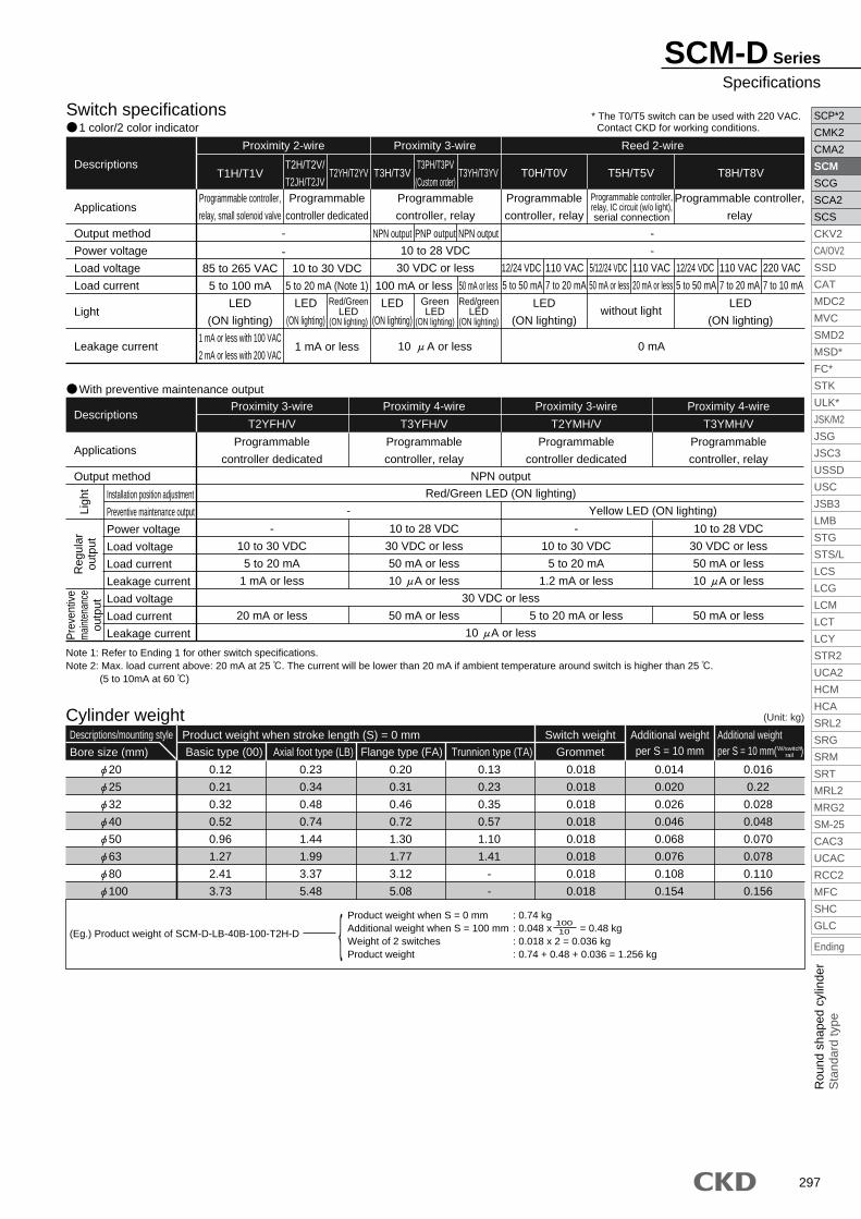
297
SCP*2
CMK2
CMA2
SCM
SCG
SCA2
SCS
CKV2
CA/OV2
SSD
CAT
MDC2
MVC
SMD2
MSD*
FC*
STK
ULK*
JSK/M2
JSG
JSC3
USSD
USC
JSB3
LMB
STG
STS/L
LCS
LCG
LCM
LCT
LCY
STR2
UCA2
HCM
HCA
SRL2
SRG
SRM
SRT
MRL2
MRG2
SM-25
CAC3
UCAC
RCC2
MFC
SHC
GLC
Ending
Rou
nd s
hape
d cy
linde
rS
tand
ard
type
SCM-D Series
Specifications
Cylinder weight
20
25
32
40
50
63
80
100
Descriptions/mounting style
Bore size (mm) Basic type (00)
0.12
0.21
0.32
0.52
0.96
1.27
2.41
3.73
Axial foot type (LB)
0.23
0.34
0.48
0.74
1.44
1.99
3.37
5.48
Flange type (FA)
0.20
0.31
0.46
0.72
1.30
1.77
3.12
5.08
Trunnion type (TA)
0.13
0.23
0.35
0.57
1.10
1.41
-
-
Grommet
0.018
0.018
0.018
0.018
0.018
0.018
0.018
0.018
0.014
0.020
0.026
0.046
0.068
0.076
0.108
0.154
0.016
0.22
0.028
0.048
0.070
0.078
0.110
0.156
Product weight when stroke length (S) = 0 mm Switch weight Additional weightper S = 10 mm
Additional weightper S = 10 mm( )
(Eg.) Product weight of SCM-D-LB-40B-100-T2H-D {Product weight when S = 0 mm : 0.74 kgAdditional weight when S = 100 mm : 0.048 x = 0.48 kgWeight of 2 switches : 0.018 x 2 = 0.036 kgProduct weight : 0.74 + 0.48 + 0.036 = 1.256 kg
10010
W/switchrail
Switch specifications 1 color/2 color indicator
Descriptions
Applications
Output method
Power voltage
Load voltage
Load current
Light
Leakage current
Programmable controller,
relay, small solenoid valve
85 to 265 VAC
5 to 100 mA
LED
(ON lighting)
1 mA or less with 100 VAC
2 mA or less with 200 VAC
Programmable
controller dedicated
10 to 30 VDC
5 to 20 mA (Note 1)
1 mA or less
-
-
10 A or less 0 mA
With preventive maintenance output
Descriptions
Applications
Output method
Programmable
controller dedicated
-
10 to 30 VDC
5 to 20 mA
1 mA or less
20 mA or less
Programmable
controller dedicated
-
10 to 30 VDC
5 to 20 mA
1.2 mA or less
5 to 20 mA or less
Programmable
controller, relay
10 to 28 VDC
30 VDC or less
50 mA or less
10 A or less
50 mA or less
Programmable
controller, relay
10 to 28 VDC
30 VDC or less
50 mA or less
10 A or less
50 mA or less
T2YFH/V T3YFH/V T2YMH/V T3YMH/V
Red/Green LED (ON lighting)
NPN output
30 VDC or less
10 A or less
Yellow LED (ON lighting)-Installation position adjustment
Preventive maintenance output
Power voltage
Load voltage
Load current
Leakage current
Load voltage
Load current
Leakage current
Reg
ular
outp
ut
Pre
vent
ive
mai
nten
ance
outp
utLi
ght
Proximity 3-wire Proximity 4-wire Proximity 3-wire Proximity 4-wire
Reed 2-wireProximity 3-wireProximity 2-wire
T1H/T1VT2H/T2V/
T2JH/T2JVT2YH/T2YV T3H/T3V
T3PH/T3PV
(Custom order)T3YH/T3YV
NPN output PNP output
10 to 28 VDC
30 VDC or less
100 mA or less
NPN output
50 mA or less
T0H/T0V T5H/T5V T8H/T8V
Red/GreenLED
(ON lighting)
Programmable
controller, relay
Programmable
controller, relay
Programmable controller,
relay
Programmable controller,relay, IC circuit (w/o light),serial connection
12/24 VDC
5 to 50 mA
110 VAC
7 to 20 mA
LED
(ON lighting)
5/12/24 VDC
50 mA or less
110 VAC
20 mA or less
without light
12/24 VDC
5 to 50 mA
220 VAC
7 to 10 mA
110 VAC
7 to 20 mA
LED
(ON lighting)
LED
(ON lighting)
GreenLED
(ON lighting)
Red/greenLED
(ON lighting)
LED
(ON lighting)
-
-
Note 1: Refer to Ending 1 for other switch specifications.Note 2: Max. load current above: 20 mA at 25 . The current will be lower than 20 mA if ambient temperature around switch is higher than 25 . (5 to 10mA at 60 )
(Unit: kg)
* The T0/T5 switch can be used with 220 VAC. Contact CKD for working conditions.

298
SCP*2
CMK2
CMA2
SCM
SCG
SCA2
SCS
CKV2
CA/OV2
SSD
CAT
MDC2
MVC
SMD2
MSD*
FC*
STK
ULK*
JSK/M2
JSG
JSC3
USSD
USC
JSB3
LMB
STG
STS/L
LCS
LCG
LCM
LCT
LCY
STR2
UCA2
HCM
HCA
SRL2
SRG
SRM
SRT
MRL2
MRG2
SM-25
CAC3
UCAC
RCC2
MFC
SHC
GLC
Ending
SCM-D Series
<Example of model number>SCM-D-LB-40B-100-T2H-D-JI
Model: Round shaped cylinder double acting double rod type
Mounting style : Axial foot type
Bore size : 40 mm
Port thread type : Rc thread
Cushion : Both sides air cushioned
Stroke length : 100 mm
Switch model no. : Proximity T2H switch, lead wire 1 m
Switch quantity : 2
Switch installation method : Rail method
Option : Bellows material / max. ambient temperature 60
Accessory : Rod eye
A
B
C
D
E
F
G
H
I
J
A
How to order
Without switch
With switch
Mounting style
SCM-D T2H100 JDB I40LB
SCM-D 100 JB I40LB
I OptionNote 4Note 6
J Accessory
Note on model no. selection
H Switch installation method
G Switch quantity
F Switch model no.Note 3
E Stroke length
D Cushion
C Port thread type
B Bore size
Note 1: The mounting bracket is shipped with the product.
Note 2: Refer to page 296 for switch quantity and min. stroke length.
Note 3: Switches other than switch model no. "F" are available.
(Custom order)
Refer to Ending 1 for details.
Note 4: The instantaneous maximum temperature is that at
which sparks, swarf, etc., temporarily contact bellows.
Note 5: Refer to Ending 89 about custom specifications of rod end form.
Note 6: When the switch mounting type "Z" is selected, the
switch rail enclosed shipment "Q" cannot be selected.
Symbol Descriptions
00LBFATA
Bore size ( )Basic typeAxial foot typeRod end flange typeRod end trunnion type
20 25 32 40 50 63 80 100Mounting styleA
Bore size (mm)B
CushionD
Stroke length (mm)E
Port thread typeC
Bore size Stroke length Custom stroke length 20 to 100 10 to 600 Per 1 mm
20253240506380100
20253240506380100
BlankNG
Rc threadNPT thread (custom order)G thread (custom order)
BRHD
Both sides air cushionedRod end air cushionedHead end air cushionedBoth sides rubber cushioned
20 25 32 40 50 63 80 100
Switch quantityG
OptionI
AccessoryJ
Max. ambient60 100 250
Max. instantaneous100 200 400
Switch installation methodH
BlankZ
Rail methodBand method
RHDT4
One on rod endOne on head endTwoThree4 switches (When more than 4 switches, indicate switch quantity.)
JKLQMP6
BellowsBellowsBellowsSwitch rail attached at shipmentPiston rod material (stainless steel)Copper and PTFE free
IY
B2
Bore size ( )Rod eyeRod clevis (pin and snap ring attached)Clevis bracket
Switch model no.F
*Lead wire length
1 color indicator typewithout light
1 color indicator type
1 color indicator type
1 color indicator type (custom order)
2 color indicator type
Strong magnetic field proof switch
Off-delay type
2-wire
2-wire
3-wire
2-wire3-wire3-wire4-wire3-wire4-wire
2-wire
2-wire
Conta
ctP
roxi
mity
Ree
d
Indicator Lead wireAxial lead
wireT0H*T5H*T8H*T1H*T2H*T3H*
T3PH*T2YH*T3YH*
T2YFH*T3YFH*T2YMH*T3YMH*T2YD*
T2YDT*T2JH*
Radial leadwireT0V*T5V*T8V*T1V*T2V*T3V*
T3PV*T2YV*T3YV*
T2YFV*T3YFV*T2YMV*T3YMV*
--
T2JV*
Blank35
1 m (standard)3 m (option)5 m (option)
2 color indicator type(W/o light for preventive
maintenance output)2 color indicator type
(W/ light for preventivemaintenance output (1 color))

299
SCP*2
CMK2
CMA2
SCM
SCG
SCA2
SCS
CKV2
CA/OV2
SSD
CAT
MDC2
MVC
SMD2
MSD*
FC*
STK
ULK*
JSK/M2
JSG
JSC3
USSD
USC
JSB3
LMB
STG
STS/L
LCS
LCG
LCM
LCT
LCY
STR2
UCA2
HCM
HCA
SRL2
SRG
SRM
SRT
MRL2
MRG2
SM-25
CAC3
UCAC
RCC2
MFC
SHC
GLC
Ending
Rou
nd s
hape
d cy
linde
rS
tand
ard
type
SCM-D Series
How to order
How to order mounting bracket
Note 1:When more than 300 mm stroke, indicate "X". When more than 300 mm stroke, a short rail (100 mm switch adjustment distance) is provided per switch.Note 2:When X is indicated only with the mounting rail, order the same number of rails as the number of switches being used.
Mounting rail
Note 1: Mounting bolts are attached to each mounting bracket.Note 2: 2 piece/set is applied for a foot type mounting bracket.
SCM-LB-20
SCM-FA-20
SCM-TA-20
20
SCM-LB-25
SCM-FA-25
SCM-TA-25
25
SCM-LB-32
SCM-FA-32
SCM-TA-32
32
SCM-LB-40
SCM-FA-40
SCM-TA-40
40
SCM-LB-50
SCM-FA-50
SCM-TA-50
50
SCM-LB-63
SCM-FA-63
SCM-TA-63
63
SCM-LB-80
SCM-FA-80
-
80
SCM-LB-100
SCM-FA-100
-
100
Foot (LB)
Flange (FA)
Trunnion (TA)
Bore size (mm)
Mounting bracket
Switch model no.(Item previous page)
Switch body + mounting rail set
SCM T0H D 40
F BB
G E E
Bore size(Item previous page)
Switch quantity(Item previous page)
Stroke length (Note 1)(Item previous page)
T0HSW
100Only mounting rail
SCM T 40
Bore size(Item previous page)
(Note 1)Stroke length (Note 2)
(Item previous page)
100
(switch installation method: rail method)
How to order switch
Switch model no.(Item previous page)
Switch body + mounting rail + band
SCM T2H* 40
F
B
Bore size(Item previous page)
Z
(switch installation method: band method)
(only switch body)
Mounting rail + band
SCM 40
B
Bore size(Item previous page)
Z
F
Switch model no.(Item previous page)

300
SCP*2
CMK2
CMA2
SCM
SCG
SCA2
SCS
CKV2
CA/OV2
SSD
CAT
MDC2
MVC
SMD2
MSD*
FC*
STK
ULK*
JSK/M2
JSG
JSC3
USSD
USC
JSB3
LMB
STG
STS/L
LCS
LCG
LCM
LCT
LCY
STR2
UCA2
HCM
HCA
SRL2
SRG
SRM
SRT
MRL2
MRG2
SM-25
CAC3
UCAC
RCC2
MFC
SHC
GLC
Ending
SCM-D Series
Rubber cushioned 20 to 40 50 to 100
Air cushioned 20 to 40
50 to 100
Note 1: Oil impregnated cast iron bearing is used for copper and PTFE free. Note 2: For 50 and 63 mm bore cylinders, aluminum alloy die casting is used, and its surface is painted.Note 3: The (22) switch and (23) switch rail are mounted only when the type with switch is selected.
Internal structure and parts list
1
2
3
4
5
6
7
8
9
10
11
12
Rod nut
Piston rod A
Rod packing seal
Bush
Rod cover
Cylinder gasket
Cylinder tube
Cushion rubber
Piston R
Piston packing seal
Piston gasket
Magnet
Parts name
Steel
20, 25: stainless steel
32 to 100: steel
Nitrile rubber
Oil impregnated bearing alloy *1
Aluminum alloy Note 2
Nitrile rubber
Aluminum alloy
Urethane rubber
20 to 40: aluminum alloy
50 to 100: aluminum alloy die-casting
Nitrile rubber
Nitrile rubber
Plastic
Material
Nickeling
Industrial chrome plating
Paint
Hard alumite
RemarksNo.
13
14
Air cushioned
15
16
17
18
19
20
21
With switch
22
23
Piston H
Piston rod B
Needle gasket
Holder gasket
Needle holder
Lock nut
Needle
Dial
Cushion packing seal
Switch
Switch rail
Industrial chrome plating
Nickeling
Parts name
20 to 40: aluminum alloy
50 to 100: aluminum alloy die-casting
20, 25: stainless steel
32 to 100: steel
Nitrile rubber
Nitrile rubber
Aluminum alloy
Steel
Stainless steel
Aluminum alloy
Nitrile rubber and steel
Aluminum alloy
Material RemarksNo.
1 2 3 11 144 5 6 7 138 9 10 12 1 2 3 13 144 5 6 7 118 10 12 92223 2223
1 2 3 11 144 5 6 7 138 9 1021 1223 22 16 1715 19 20 18
23 22 16 1715 19 20 18 1 2 3 13 144 5 6 7 1121 10 12 9

301
SCP*2
CMK2
CMA2
SCM
SCG
SCA2
SCS
CKV2
CA/OV2
SSD
CAT
MDC2
MVC
SMD2
MSD*
FC*
STK
ULK*
JSK/M2
JSG
JSC3
USSD
USC
JSB3
LMB
STG
STS/L
LCS
LCG
LCM
LCT
LCY
STR2
UCA2
HCM
HCA
SRL2
SRG
SRM
SRT
MRL2
MRG2
SM-25
CAC3
UCAC
RCC2
MFC
SHC
GLC
Ending
Rou
nd s
hape
d cy
linde
rS
tand
ard
type
20
25
32
40
50
63
80
100
SCM-D-20DK
SCM-D-25DK
SCM-D-32DK
SCM-D-40DK
SCM-D-50DK
SCM-D-63DK
SCM-D-80DK
SCM-D-100DK
TubeInner diameter (mm)
Kit No. Repair parts number
Repair parts list
20
25
32
40
50
63
80
100
SCM-D-20BK
SCM-D-25BK
SCM-D-32BK
SCM-D-40BK
SCM-D-50BK
SCM-D-63BK
SCM-D-80BK
SCM-D-100BK
With air cushion
TubeInner diameter (mm)
Kit No. Repair parts number
3 6 8 10 3 6 8
10 21
Note 2
With rubber cushion
Note 1: , and are the same as the rubber cushioned.Note 2: (8) is not attached to 50 to 100 cylinder.
Note: When placing an order, indicate kit number.
3 6 10
SCM-D Series
Repair parts list

302
SCP*2
CMK2
CMA2
SCM
SCG
SCA2
SCS
CKV2
CA/OV2
SSD
CAT
MDC2
MVC
SMD2
MSD*
FC*
STK
ULK*
JSK/M2
JSG
JSC3
USSD
USC
JSB3
LMB
STG
STS/L
LCS
LCG
LCM
LCT
LCY
STR2
UCA2
HCM
HCA
SRL2
SRG
SRM
SRT
MRL2
MRG2
SM-25
CAC3
UCAC
RCC2
MFC
SHC
GLC
Ending
Double acting double rod type (00)
Both sides with bellows
<Air cushioned> (Note) For 20, 25 cylinder, piping method (EE) are different. Refer to air cushioned dimensions table (EE*).
20, 25
*Axial foot type (LB)
20253240506380100
Note 3: Refer to the page 333 for the RD, HD, and projecting dimensions of the 2-color indicator type, preventive maintenance output type, off delay type, strong magnetic field proof type, T1H/V, T8H/V switch.Note 4: Refer to page 334 and 335 for accessory dimensions.
Note 1: Needle relevant dimensions and port size of air cushioned types are same as basic type. Refer to page 231.Note 2: The position of the across flat for catching the wrench on the left and right is not specified.
Note: Each mounting style installation dimension is same as SCM (double acting). Refer to pages 232 to 243. Refer to the above drawing for the radial direction foot type (LB).
Dimensions
566811111316
T
1718182023233131
141151153179209209250250
WF
With bellows Air cushioned Switch installation method: rail method
X
3540405058587171
XF
(stroke length/3) + 18.5(stroke length/3) + 20.5(stroke length/3) + 19 (stroke length/3) + 18.5
(stroke length/3.6) + 18.5(stroke length/3.6) + 18.5(stroke length/4.3) + 14.5(stroke length/4.5) + 21
M5M5
Rc1/8Rc1/8Rc1/4Rc1/4Rc3/8Rc1/2
EE*
30°30°25°20°20°20°20°20°
E
14141415
18.518.52020
EA
2729.532.836.64350
58.569
EC T0, T5HD RD
19.522
25.530
35.542.551
61.5
P
2324.425
25.726.226.526.726.7
GB
3035
31.54046465556
b
47.247.247.252.258586060
LX'
3030353540405060
d
25.730.737.746.757.771.788.7109.7
s T2, T3 T0, T5 T2, T3
Symbol
Bore size (mm)
<Rubber cushioned>· Switch installation method: rail method
· Switch installation method: rail method
4.03.04.06.08.08.010.511.0
7.06.07.09.011.511.513.013.5
7.08.09.011.012.012.019.018.5
7.58.59.511.513.013.020.019.5
20253240506380100
1822223035354040
15.519.519.52732323737
A1317172227273241
B
Basic type (00) basic dimensions
C26313847587289110
DM4 depth 6.5M5 depth 6.5M5 depth 7.5M6 depth 12M8 depth 16M10 depth 16M10 depth 22M12 depth 22
DARc1/8Rc1/8Rc1/8Rc1/8Rc1/4Rc1/4Rc3/8Rc1/2
EE (note)1214182530324050
JM8
M10 x 1.25
M10 x 1.25
M14 x 1.5
M18 x 1.5
M18 x 1.5
M22 x 1.5
M26 x 1.5
KK717173799393108108
LL111111121313--
MA24293644556980100
MCM5M6M8M10M12M14
--
MD810121620202530
MM68101417172227
MN45
5.56881113
MO22222233
N1212121315151515
QA14
16.5202632385060
SD1919192025252828
GR
Symbol
Bore size (mm)
MN (width across flats)
MM
J
JD
MO
SD
SD
8-DA
MC
GB
18
A
C
C N GR GR
QAT
RD HD
2-EE
2KKKK
XF MA MA4-MDMO
WFA
N C
AWF
X + 2 x stroke length
XF + stroke length
LL + stroke length WF + stroke length
P
Width across flats B
KK
TQA
M
M
ds d s
A
b
WF +
XF +
X + 2 x ( + stroke length)
XF + + stroke length
LL + stroke length A
b
WF + + stroke length
A
EC (m
ax.)
C
2KK
E 10°
MO
WFEA
Air cushionNeedle
EE*
EC (m
ax.)
E 10°EA
LX' + stroke length
SCM-D Series
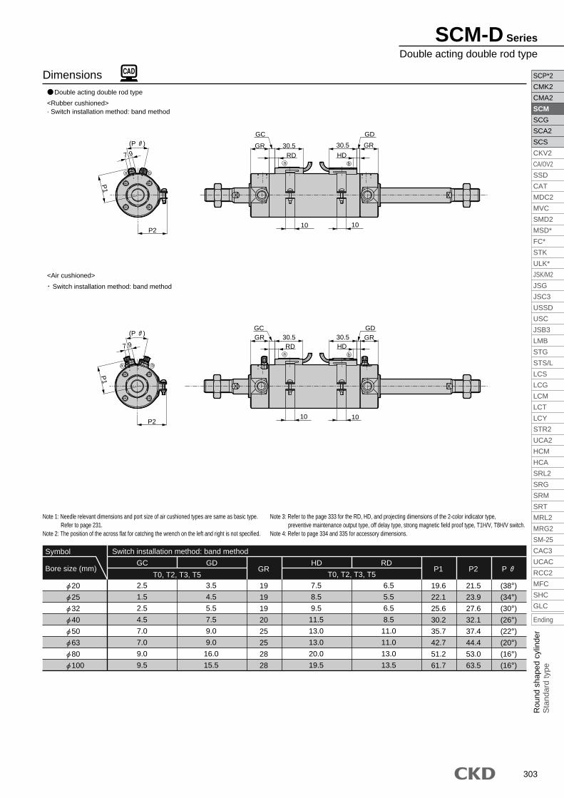
303
SCP*2
CMK2
CMA2
SCM
SCG
SCA2
SCS
CKV2
CA/OV2
SSD
CAT
MDC2
MVC
SMD2
MSD*
FC*
STK
ULK*
JSK/M2
JSG
JSC3
USSD
USC
JSB3
LMB
STG
STS/L
LCS
LCG
LCM
LCT
LCY
STR2
UCA2
HCM
HCA
SRL2
SRG
SRM
SRT
MRL2
MRG2
SM-25
CAC3
UCAC
RCC2
MFC
SHC
GLC
Ending
Rou
nd s
hape
d cy
linde
rS
tand
ard
type
Double acting double rod type
<Air cushioned>
Note 3: Refer to the page 333 for the RD, HD, and projecting dimensions of the 2-color indicator type, preventive maintenance output type, off delay type, strong magnetic field proof type, T1H/V, T8H/V switch.Note 4: Refer to page 334 and 335 for accessory dimensions.
Note 1: Needle relevant dimensions and port size of air cushioned types are same as basic type. Refer to page 231.Note 2: The position of the across flat for catching the wrench on the left and right is not specified.
20
25
32
40
50
63
80
100
Dimensions
<Rubber cushioned>· Switch installation method: band method
Switch installation method: band method
Switch installation method: band method
GC GDGR
Symbol
Bore size (mm)
19
19
19
20
25
25
28
28
HD RDP1
19.6
22.1
25.6
30.2
35.7
42.7
51.2
61.7
P2
21.5
23.9
27.6
32.1
37.4
44.4
53.0
63.5
P
(38°)
(34°)
(30°)
(26°)
(22°)
(20°)
(16°)
(16°)
3.5
4.5
5.5
7.5
9.0
9.0
16.0
15.5
T0, T2, T3, T52.5
1.5
2.5
4.5
7.0
7.0
9.0
9.5
T0, T2, T3, T5
7.5
8.5
9.5
11.5
13.0
13.0
20.0
19.5
6.5
5.5
6.5
8.5
11.0
11.0
13.0
13.5
GR(P )
10
HD
30.5
GD
RD30.5GR
10
GC
P1
7.9
P2
ba
ba
GR(P )
10
HD30.5
GD
RD30.5GR
10
GC
P1
7.9
P2
ba
ba
SCM-D Series
Double acting double rod type

304
SCP*2
CMK2
CMA2
SCM
SCG
SCA2
SCS
CKV2
CA/OV2
SSD
CAT
MDC2
MVC
SMD2
MSD*
FC*
STK
ULK*
JSK/M2
JSG
JSC3
USSD
USC
JSB3
LMB
STG
STS/L
LCS
LCG
LCM
LCT
LCY
STR2
UCA2
HCM
HCA
SRL2
SRG
SRM
SRT
MRL2
MRG2
SM-25
CAC3
UCAC
RCC2
MFC
SHC
GLC
Ending
Round shaped medium bore size cylinderDouble acting back to back type
SCM-B Series Bore size: 20, 25, 32, 40, 50, 63
JIS symbol
Note 1: Custom stroke length is available by 1 mm increment.
Note 1: Trunion mounting is not available when installing one switch with a stroke of 10 mm or more, less than 25 mm, since the switch rail mounting position will change. Refer to page 333 for installation position.
Specifications
Bore size
Actuation
Working fluid
Max. working pressure
Min. working pressure
Withstanding pressure
Ambient temperature
Port size
Stroke tolerance
Working piston speed
Cushion
Lubrication
Allowable energy absorption
20
0.1
25
0.2
32
0.5
40
0.9
50
1.6
63
1.6
Double acting back to back type
Compressed air
1.0
1.6
-10 to 60 (no freezing)
30 to 1000 (Use within the allowable energy absorption. )
Rubber cushion
Not required (when lubricating, use turbine oil ISO VG32.)
0.1
Rc1/8
0.05
Rc1/4
SCM-Bmm
MPa
MPa
MPa
mm
mm/s
J
Descriptions
Stroke lengthStandard stroke length (mm) Max. stroke length (mm) Min. stroke length (mm)Bore size (mm)
500
750
10
20
25
32
40
50
63
25, 50, 75,
100, 125, 150,
200, 250, 300
+1.4 0
(Up to 500) +1.4 0
(Up to 750) +2.3 0
(Up to 750)
Proximity Reed
Switch quantity
Bore size (mm)
1
20
25
32
40
50
63
10
10
10
10
10
10
Proximity Reed Proximity Reed
2 3
25
25
25
25
25
25
Proximity Reed
4
55
55
55
55
55
55
40
40
40
40
40
40
50
50
50
50
50
50
Proximity Reed
5
75
75
75
75
75
75
85
85
85
85
85
85
Switch quantity and min. stroke length (mm) Switch installation method: Rail method
Proximity
T2, T3 T*Y*Reed
Switch quantity
Bore size (mm)
1
Proximity
T2, T3 T*Y*Reed
2
20
25
32
40
50
63
10
10
10
10
10
10
25
25
25
25
25
25
35
35
35
35
35
35
25
25
25
25
25
25
Switch installation method: Band method
Proximity
T2, T3 T*Y*Reed
3
50
50
50
50
50
50
55
55
55
55
55
55
50
50
50
50
50
50
Proximity
T2, T3 T*Y*Reed
4
75
75
75
75
75
75
80
80
80
80
80
80
70
70
70
70
70
70
Proximity
T2, T3 T*Y*Reed
5
95
95
95
95
95
95
100
100
100
100
100
100
95
95
95
95
95
95

305
SCP*2
CMK2
CMA2
SCM
SCG
SCA2
SCS
CKV2
CA/OV2
SSD
CAT
MDC2
MVC
SMD2
MSD*
FC*
STK
ULK*
JSK/M2
JSG
JSC3
USSD
USC
JSB3
LMB
STG
STS/L
LCS
LCG
LCM
LCT
LCY
STR2
UCA2
HCM
HCA
SRL2
SRG
SRM
SRT
MRL2
MRG2
SM-25
CAC3
UCAC
RCC2
MFC
SHC
GLC
Ending
Rou
nd s
hape
d cy
linde
rS
tand
ard
type
Cylinder weight (Unit: kg)
(Eg.) Product weight of
SCM-B-LB-40D-25-T2H-D-D50-T2H-R Product weight when S = 0 mm 0.41 kg
Additional weight when S = 25 mm 0.032 x 25 = 0.08 kg
Weight of 2 switches 0.036 kg
Weight of S1 0.41 kg + 0.08 kg + 0.036 kg = 0.526 kg
(weight of S1)
10
Product weight when S = 0 mm 0.41 kg
Additional weight when S = 50 mm 0.032 x 50 = 0.16 kg
Weight of 1 switch 0.018 kg
Weight of S2 0.63 kg + 0.16 kg + 0.018 kg = 0.588kg
Product weight (weight of S1 + weight of S2 + additional weight) 0.526 kg + 0.588 kg + 0.27 kg = 1.384 kg
(weight of S2)
10
Basic type (00)
Descriptions/mounting style
Bore size (mm)
Product weight when stroke length (S) = 0 mm Additional weight Switch weight
20
25
32
40
50
63
0.10
0.17
0.26
0.41
0.77
1.07
Basic type
0.00
0.00
0.02
0.05
0.07
0.11
Axial foot type
0.11
0.13
0.18
0.27
0.55
0.83
Flange type
0.03
0.04
0.08
0.13
0.41
0.61
Trunnion type
0.01
0.02
0.05
0.10
0.21
0.25
Grommet
0.018
0.018
0.018
0.018
0.018
0.018
Additional weightper S = 10 mm
0.01
0.014
0.018
0.03
0.044
0.052
0.012
0.016
0.02
0.032
0.046
0.054
0.007
0.007
0.007
0.007
0.008
0.009
Additional weight perS = 10 mm
Band weightper 1 switchW/switch
rail
Switch specifications 1 color/2 color indicator
Descriptions
Applications
Output method
Power voltage
Load voltage
Load current
Light
Leakage current
Programmable controller,
relay, small solenoid valve
85 to 265 VAC
5 to 100 mA
LED
(ON lighting)
1 mA or less with 100 VAC
2 mA or less with 200 VAC
Programmable
controller dedicated
10 to 30 VDC
5 to 20 mA (Note 1)
1 mA or less
-
-
10 A or less 0 mA
With preventive maintenance output
Descriptions
Applications
Output method
Programmable
controller dedicated
-
10 to 30 VDC
5 to 20 mA
1 mA or less
20 mA or less
Programmable
controller dedicated
-
10 to 30 VDC
5 to 20 mA
1.2 mA or less
5 to 20 mA or less
Programmable
controller, relay
10 to 28 VDC
30 VDC or less
50 mA or less
10 A or less
50 mA or less
Programmable
controller, relay
10 to 28 VDC
30 VDC or less
50 mA or less
10 A or less
50 mA or less
T2YFH/V T3YFH/V T2YMH/V T3YMH/V
Red/Green LED (ON lighting)
NPN output
30 VDC or less
10 A or less
Yellow LED (ON lighting)-Installation position adjustment
Preventive maintenance output
Power voltage
Load voltage
Load current
Leakage current
Load voltage
Load current
Leakage current
Reg
ular
outp
ut
Prev
entiv
em
ainte
nanc
eou
tput
Ligh
t
Proximity 3-wire Proximity 4-wire Proximity 3-wire Proximity 4-wire
Reed 2-wireProximity 2-wire Proximity 3-wire
T1H/T1VT2H/T2V/
T2JH/T2JVT2YH/T2YV T3H/T3V
T3PH/T3PV
(Custom order)T3YH/T3YV
NPN output PNP output
10 to 28 VDC
30 VDC or less
100 mA or less
NPN output
50 mA or less
T0H/T0V T5H/T5V T8H/T8V
Red/GreenLED
(ON lighting)
Programmable
controller, relay
Programmable
controller, relay
Programmable controller,
relay
Programmable controller,relay, IC circuit (w/o light),serial connection
12/24 VDC
5 to 50 mA
110 VAC
7 to 20 mA
LED
(ON lighting)
5/12/24 VDC
50 mA or less
110 VAC
20 mA or less
without light
12/24 VDC
5 to 50 mA
220 VAC
7 to 10 mA
110 VAC
7 to 20 mA
LED
(ON lighting)
LED
(ON lighting)
GreenLED
(ON lighting)
Red/greenLED
(ON lighting)
LED
(ON lighting)
-
-
Note 1: Refer to Ending 1 for other switch specifications.Note 2: Max. load current above: 20 mA at 25 . The current will be lower than 20 mA if ambient temperature around switch is higher than 25 . (5 to 10mA at 60 )
* The T0/T5 switch can be used with 220 VAC. Contact CKD for working conditions.
( )
SCM-B Series
Specifications

306
SCP*2
CMK2
CMA2
SCM
SCG
SCA2
SCS
CKV2
CA/OV2
SSD
CAT
MDC2
MVC
SMD2
MSD*
FC*
STK
ULK*
JSK/M2
JSG
JSC3
USSD
USC
JSB3
LMB
STG
STS/L
LCS
LCG
LCM
LCT
LCY
STR2
UCA2
HCM
HCA
SRL2
SRG
SRM
SRT
MRL2
MRG2
SM-25
CAC3
UCAC
RCC2
MFC
SHC
GLC
Ending
A
How to order
Without switch
With switch
Mounting styleNote 1
I OptionNote 4Note 6
J Accessory
LB JRD YD T0HT0H40 25 D 50SCM-B
LB JD Y40 25 D 50SCM-B
Stroke length of cylinder 1 Stroke length of cylinder 2
Cylinder 1 Cylinder 2
S1 S2
Model: Round shaped cylinder double acting back to back type
Mounting style : Axial foot type
Bore size : 40 mm
Port thread type : Rc thread
Cushion : Both sides rubber cushioned
Stroke length : S1 = 25 mm
Cushion : Both sides rubber cushioned
Stroke length : S2 = 50 mm
Switch model no. : Reed T0H switch,
lead wire 1 m
Switch quantity : Cylinder 1; 2 pcs.
Cylinder 2; 1 pc. on rod end
Switch installation method: Rail method
Option: Bellows material, max. ambient temperature 60
Accessory : Rod clevis
<Example of model number>SCM-B-LB-40-D25-T0H-D-D50-T0H-R-JY
A
B
C
D
D
E
E
G
H
I
J
F
Cylinder 1 stroke length 25 mm indicated by S1+ Cylinder 2 stroke length 50 mm indicated by S2 Total stroke length 75 mm S1 + S2
Cylinder 1
Cylinder 2
S1 S2
H Switch installation method
G Switch quantity G Switch quantity
F Switch model no.Note 3
F Switch model no.
E Stroke length= S1
E Stroke length= S2
D Cushion D Cushion
Note on model no. selectionNote 1: The mounting bracket is shipped with the product.
Note 2: Refer to page 304 for switch quantity and min. stroke length.
Note 3: Switches other than switch model no. "F" are also available.
(Custom order)
Refer to Ending 1 for details.
Note 4: The instantaneous maximum temperature is that at
which sparks, swarf, etc., temporarily contact bellows.
Note 5: Refer to Ending 89 about custom specifications of rod end form.
Note 6: When the switch mounting type "Z" is selected,
the switch rail enclosed shipment "Q" cannot be selected.
C Port thread type
B Bore size
Symbol Descriptions
00LBFAFBTATB
Mounting styleA
Bore size (mm)
Cushion
Stroke length (mm)
Basic typeAxial foot typeCylinder 1 side flange typeCylinder 2 side flange typeCylinder 1 side trunnion typeCylinder 2 side trunnion type
Bore size 20 to 32 40 to 63
Stroke length Note 210 to 50010 to 750
Custom stroke length
Per 1 mm
B
D
E
202532405063
202532405063
Port thread typeC
BlankNG
Rc threadNPT thread (custom order)G thread (custom order)
D Both sides rubber cushioned
Switch quantity
Option
AccessoryJ
Switch installation methodH
G
I
Max. ambient60 100 250
Max. instantaneous100 200 400
RHDT4
One on rod endOne on head endTwoThree4 switches (When more than 4 switches, indicate switch quantity.)
BlankZ
Rail methodBand method
JKLQMP6
BellowsBellowsBellowsSwitch rail attached at shipmentPiston rod material (stainless steel)Copper and PTFE free
IY
B2
Rod eyeRod clevis (pin and snap ring attached)Clevis bracket
Switch model no.
*Lead wire length
F
Indicator
1 color indicator typewithout light1 color indicator type
1 color indicator type
1 color indicator type (custom)
2 color indicator type
Strong magneticfield proof switchOff-delay type
Cont
act
Ree
dP
roxi
mity
Lead wire
2-wire
2-wire
3-wire
2-wire3-wire3-wire4-wire3-wire4-wire
2-wire
2-wire
Axial leadwireT0H*T5H*T8H*T1H*T2H*T3H*
T3PH*T2YH*T3YH*
T2YFH*T3YFH*T2YMH*T3YMH*T2YD*
T2YDT*T2JH*
Radial leadwireT0V*T5V*T8V*T1V*T2V*T3V*
T3PV*T2YV*T3YV*
T2YFV*T3YFV*T2YMV*T3YMV*
--
T2JV*
Blank35
1 m (standard)3 m (option)5 m (option)
2 color indicator type
2 color indicator type
(W/o light for preventivemaintenance output)
(W/ light for preventivemaintenance output (1 color))
SCM-B Series

307
SCP*2
CMK2
CMA2
SCM
SCG
SCA2
SCS
CKV2
CA/OV2
SSD
CAT
MDC2
MVC
SMD2
MSD*
FC*
STK
ULK*
JSK/M2
JSG
JSC3
USSD
USC
JSB3
LMB
STG
STS/L
LCS
LCG
LCM
LCT
LCY
STR2
UCA2
HCM
HCA
SRL2
SRG
SRM
SRT
MRL2
MRG2
SM-25
CAC3
UCAC
RCC2
MFC
SHC
GLC
Ending
Rou
nd s
hape
d cy
linde
rS
tand
ard
type
How to order mounting bracket
Note 1:When more than 300 mm stroke, indicate "X".When more than 300 mm stroke, a short rail(100 mm switch adjustment distance) is provided per switch.
Note 2:When X is indicated only with the mounting rail,order the same number of rails as the number of switches being used.
Mounting rail
Note 1: Mounting bolts are attached to each mounting bracket.Note 2: 2 piece/set is applied for a foot type mounting bracket.
SCM-LB-20
SCM-FA-20
SCM-TA-20
20
SCM-LB-25
SCM-FA-25
SCM-TA-25
25
SCM-LB-32
SCM-FA-32
SCM-TA-32
32
SCM-LB-40
SCM-FA-40
SCM-TA-40
40
SCM-LB-50
SCM-FA-50
SCM-TA-50
50
SCM-LB-63
SCM-FA-63
SCM-TA-63
63
Foot (LB)
Flange (FA)
Trunnion (TA)
Bore size (mm)
Mounting bracket
Switch model no.(Item previous page)
Switch body + mounting rail set
SCM T0H D 40
F B
B
G E
E
Bore size(Item previous page)
Switch quantity(Item previous page)
Stroke length (Note 1)(Item previous page)
T0HSW
100
Only mounting rail
SCM T 40
Bore size(Item previous page)
(Note 1)Stroke length (Note 2)
(Item previous page)
100
(switch installation method: rail method)
How to order switch
Switch model no.(Item previous page)
Switch body + mounting rail + band
SCM T2H* 40
F
B
Bore size(Item previous page)
Z
(switch installation method: band method)
(only switch body)
Mounting rail + band
SCM 40
B
Bore size(Item previous page)
Z
F
Switch model no.(Item previous page)
SCM-B Series
How to order

308
SCP*2
CMK2
CMA2
SCM
SCG
SCA2
SCS
CKV2
CA/OV2
SSD
CAT
MDC2
MVC
SMD2
MSD*
FC*
STK
ULK*
JSK/M2
JSG
JSC3
USSD
USC
JSB3
LMB
STG
STS/L
LCS
LCG
LCM
LCT
LCY
STR2
UCA2
HCM
HCA
SRL2
SRG
SRM
SRT
MRL2
MRG2
SM-25
CAC3
UCAC
RCC2
MFC
SHC
GLC
Ending
SCM-B Series
Repair parts list
Internal structure and parts list
Three positions are available when the same stroke is combined. Four positions are available when different strokes are combined.
Applications
1
2
3
Rod packing seal
Cylinder gasket
Piston packing seal
Parts name
Nitrile rubber
Nitrile rubber
Nitrile rubber
Material RemarksNo.
4
5
6
Wear ring
Intermediate guard
Cushion rubber
Parts name
Polyacetal resin
Aluminum alloy
Urethane rubber
Material
Paint
RemarksNo.
21 3 4 6
Bore size (mm)
20
25
32
40
50
63
SCM-B-20DK
SCM-B-25DK
SCM-B-32DK
SCM-B-40DK
SCM-B-50DK
SCM-B-63DK
Kit No. Repair parts number
Reference3 2 1 Reference4 3 2 1
21 6 3 4 5

309
SCP*2
CMK2
CMA2
SCM
SCG
SCA2
SCS
CKV2
CA/OV2
SSD
CAT
MDC2
MVC
SMD2
MSD*
FC*
STK
ULK*
JSK/M2
JSG
JSC3
USSD
USC
JSB3
LMB
STG
STS/L
LCS
LCG
LCM
LCT
LCY
STR2
UCA2
HCM
HCA
SRL2
SRG
SRM
SRT
MRL2
MRG2
SM-25
CAC3
UCAC
RCC2
MFC
SHC
GLC
Ending
Rou
nd s
hape
d cy
linde
rS
tand
ard
type
SCM-B Series
Double acting back to back type
· Switch installation method: rail method
· Switch installation method: band method
3.5
4.5
5.5
7.5
9.0
9.0
T0, T2, T3, T5
2.5
1.5
2.5
4.5
7.0
7.0
T0, T2, T3, T5
7.5
8.5
9.5
11.5
13.0
13.0
6.5
5.5
6.5
8.5
11.0
11.0
Double acting back to back type
Dimensions
Note 1: Refer to the page 333 for the RD, HD, and projecting dimensions of the 2-color indication type, preventive maintenance output type, off delay type, strong magnetic field proof type, T1H/V, T8H/V switch.Note 2: Refer to page 334 and 335 for accessory dimensions. *: S1 = Stroke length of cylinder 1, S2 = Stroke length of cylinder 2
QD
7
7
7
7
10
10
20
25
32
40
50
63
Symbol
Bore size (mm) QE
59
59
61
66
78
78
SD
14
16.5
20
26
32
38
T
5
6
6
8
11
11
WF
17
18
18
20
23
23
X
207
217
223
257
300
300
b
30
35
31.5
40
46
46
d
30
30
35
35
40
40
s
25.7
30.7
37.7
46.7
57.7
71.7
XF
35
40
40
50
58
58
(stroke length/3) + 18.5
(stroke length/3) + 20.5
(stroke length/3) + 19
(stroke length/3) + 18.5
(stroke length/3.6) + 18.5
(stroke length/3.6) + 18.5
P
19.5
22
25.5
30
35.5
42.5
GBHD RD
23
24.4
25
25.7
26.2
26.5
GC GDWith bellows Switch installation method: rail method
Note: Each mounting style installation dimension is same as SCM (double acting). Refer to pages 232 to 243.
20
25
32
40
50
63
Symbol
Bore size (mm) P1 P2 P HD RD
19.6
22.1
25.6
30.2
35.7
42.7
21.5
23.9
27.6
32.1
37.4
44.4
(38°)
(34°)
(30°)
(26°)
(22°)
(20°)
Switch installation method: band method
Switch installation method: band method
4.0
3.0
4.0
6.0
8.0
8.0
T0, T5
7.0
6.0
7.0
9.0
11.5
11.5
T2, T3
7.0
8.0
9.0
11.0
12.0
12.0
T0, T5
7.5
8.5
9.5
11.5
13.0
13.0
T2, T3
20
25
32
40
50
63
Symbol
Bore size (mm) A
18
22
22
30
35
35
B
13
17
17
22
27
27
C
15.5
19.5
19.5
27
32
32
D
26
31
38
47
58
72
DA
M4 depth 6.5
M5 depth 6.5
M5 depth 7.5
M6 depth 12
M8 depth 16
M10 depth 16
EE
Rc1/8
Rc1/8
Rc1/8
Rc1/8
Rc1/4
Rc1/4
J KK
M8
M10 x 1.25
M10 x 1.25
M14 x 1.5
M18 x 1.5
M18 x 1.5
LL
137
137
143
157
184
184
MA
11
11
11
12
13
13
MC
24
29
36
44
55
69
MD
M5
M6
M8
M10
M12
M14
MM
8
10
12
16
20
20
MN
6
8
10
14
17
17
MO
4
5
5.5
6
8
8
QA
12
12
12
13
15
15
QC
19
19
21
25
28
28
Basic type (00) basic dimensions
19
19
19
20
25
25
GR
12
14
18
25
30
32
M
M
M
M
J
J
D
d
s
MO
MN (width across flats)
SD
SD
8-DA
MC
GB
18
A
C
C 2 GR
QAT
RD HD
QC QDQD
2KKKK
XF XFMA MA4-MD
Cylinder 1Width across
flats B
Cylinder 2
4-MD
MO
WF
A WF AWF
A
b
WF +
XF +
X + + stroke length
X + S1* + S2*
LL + S1* + S2*QE + S1*
P
HD C2GR
QA
RD
With bellows 20, 25
4-EE
HD
30.5
GD
RD
30.5 GR
10
GC(P )
10
HD
30.5
GD
RD
30.5GR
10
GC
P1
7.9
P2
a c
c dba
bd
10

310
SCP*2
CMK2
CMA2
SCM
SCG
SCA2
SCS
CKV2
CA/OV2
SSD
CAT
MDC2
MVC
SMD2
MSD*
FC*
STK
ULK*
JSK/M2
JSG
JSC3
USSD
USC
JSB3
LMB
STG
STS/L
LCS
LCG
LCM
LCT
LCY
STR2
UCA2
HCM
HCA
SRL2
SRG
SRM
SRT
MRL2
MRG2
SM-25
CAC3
UCAC
RCC2
MFC
SHC
GLC
Ending
Round shaped medium bore size cylinderDouble acting two stage type
SCM-W Series Bore size: 20, 25, 32, 40, 50, 63
Specifications
Bore size
Actuation
Working fluid
Max. working pressure
Min. working pressure
Withstanding pressure
Ambient temperature
Port size
Stroke tolerance mm
Working piston speed
Cushion
Lubrication
Allowable energy absorption
20
0.1
25
0.2
32
0.5
40
0.9
50
1.6
63
1.6
Double acting two stage type
Compressed air
1.0 (Note 1)
1.6
-10 to 60 (no freezing)
50 to 1000 (Use within the allowable energy absorption. )
Rubber cushion
Not required (when lubricating, use turbine oil ISO VG32.)
0.2
Rc1/8
1.4
+1.4
0
0.1
Rc1/4
2.3
+2.3
0
SCM-Wmm
MPa
MPa
MPa
S1
S2
mm/s
J
Descriptions
Note 1: Custom stroke length is available per 1 mm increment.Note 2: Max. stroke length of S2 is 200 mm.Note 3: Strokes exceeding 600 mm are available as custom order parts. Contact CKD for details.
Note 1: If S1 and S2 are the same, the maximum working pressure must be 0.5 MPa.
Note 1: Trunion mounting is not available when installing one switch with a stroke of 10 mm or more, less than 25 mm, since the switch rail mounting position will change. Refer to page 333 for installation position.
Stroke lengthStandard stroke length (mm) Max. stroke length (mm) Min. stroke length (mm)Bore size (mm)
600 10
20
25
32
40
50
63
25, 50, 75,
100, 125, 150,
200, 250, 300
Proximity Reed
Switch quantity
Bore size (mm)
1
20
25
32
40
50
63
10
10
10
10
10
10
Proximity Reed Proximity Reed
2 3
25
25
25
25
25
25
Proximity Reed
4
55
55
55
55
55
55
40
40
40
40
40
40
50
50
50
50
50
50
Proximity Reed
5
75
75
75
75
75
75
85
85
85
85
85
85
Switch quantity and min. stroke length (mm) Switch installation method: Rail method
Proximity
T2, T3 T*Y*Reed
Switch quantity
Bore size (mm)
1
Proximity
T2, T3 T*Y*Reed
2
20
25
32
40
50
63
10
10
10
10
10
10
25
25
25
25
25
25
35
35
35
35
35
35
25
25
25
25
25
25
Switch installation method: Band method
Proximity
T2, T3 T*Y*Reed
3
50
50
50
50
50
50
55
55
55
55
55
55
50
50
50
50
50
50
Proximity
T2, T3 T*Y*Reed
4
75
75
75
75
75
75
80
80
80
80
80
80
70
70
70
70
70
70
Proximity
T2, T3 T*Y*Reed
5
95
95
95
95
95
95
100
100
100
100
100
100
95
95
95
95
95
95

311
SCP*2
CMK2
CMA2
SCM
SCG
SCA2
SCS
CKV2
CA/OV2
SSD
CAT
MDC2
MVC
SMD2
MSD*
FC*
STK
ULK*
JSK/M2
JSG
JSC3
USSD
USC
JSB3
LMB
STG
STS/L
LCS
LCG
LCM
LCT
LCY
STR2
UCA2
HCM
HCA
SRL2
SRG
SRM
SRT
MRL2
MRG2
SM-25
CAC3
UCAC
RCC2
MFC
SHC
GLC
Ending
Rou
nd s
hape
d cy
linde
rS
tand
ard
type
Cylinder weight (Unit: kg)
(Eg.) Product weight of
SCM-W-LB-40-D100-T2H-D-D25-T2H-R Product weight when S = 0 mm 0.41 kg
Additional weight when S = 100 mm 0.032 x 100 = 0.32 kg
Weight of 2 switches 0.036 kg
Weight of S1 0.41 kg + 0.32 kg + 0.036 kg = 0.766 kg
(weight of S1)
10
Product weight when S = 0 mm 0.41 kg
Additional weight when S = 25 mm 0.032 x 25 = 0.08 kg
Weight of 1 switch 0.018 kg
Weight of S2 0.41 kg + 0.08 kg + 0.018 kg = 0.508 kg
Product weight (weight of S1 + weight of S2 + additional weight) 0.766 kg + 0.508 kg + 0.19 kg = 1.464 kg
(weight of S2)
10
Basic type (00)
Descriptions/mounting style
Bore size (mm)
Product weight when stroke length (S) = 0 mm Additional weight Switch weight
20
25
32
40
50
63
0.10
0.17
0.26
0.41
0.77
1.07
Basic type
-0.01
-0.02
-0.01
-0.03
-0.06
-0.02
Axial foot type
0.10
0.11
0.15
0.19
0.42
0.70
Flange type
0.02
0.02
0.05
0.05
0.28
0.48
Clevis type
0.04
0.06
0.14
0.20
0.34
0.66
Trunnion type
0.00
0.00
0.02
0.02
0.08
0.12
Grommet
0.018
0.018
0.018
0.018
0.018
0.018
Additional weightper S = 10 mm
0.01
0.014
0.018
0.03
0.044
0.052
0.012
0.016
0.02
0.032
0.046
0.054
0.007
0.007
0.007
0.007
0.008
0.009
Additional weight perS = 10 mm
Band weight per1 switchW/switch
rail
Switch specifications 1 color/2 color indicator
Descriptions
Applications
Output method
Power voltage
Load voltage
Load current
Light
Leakage current
Programmable controller,
relay, small solenoid valve
85 to 265 VAC
5 to 100 mA
LED
(ON lighting)
1 mA or less with 100 VAC
2 mA or less with 200 VAC
Programmable
controller dedicated
10 to 30 VDC
5 to 20 mA (Note 1)
1 mA or less
-
-
10 A or less 0 mA
With preventive maintenance output
Descriptions
Applications
Output method
Programmable
controller dedicated
-
10 to 30 VDC
5 to 20 mA
1 mA or less
20 mA or less
Programmable
controller dedicated
-
10 to 30 VDC
5 to 20 mA
1.2 mA or less
5 to 20 mA or less
Programmable
controller, relay
10 to 28 VDC
30 VDC or less
50 mA or less
10 A or less
50 mA or less
Programmable
controller, relay
10 to 28 VDC
30 VDC or less
50 mA or less
10 A or less
50 mA or less
T2YFH/V T3YFH/V T2YMH/V T3YMH/V
Red/Green LED (ON lighting)
NPN output
30 VDC or less
10 A or less
Yellow LED (ON lighting)-Installation position adjustment
Preventive maintenance output
Power voltage
Load voltage
Load current
Leakage current
Load voltage
Load current
Leakage current
Reg
ular
outp
ut
Pre
vent
ive
main
tena
nce
outp
utLi
ght
Proximity 3-wire Proximity 4-wire Proximity 3-wire Proximity 4-wire
Reed 2-wireProximity 2-wire Proximity 3-wire
T1H/T1VT2H/T2V/
T2JH/T2JVT2YH/T2YV T3H/T3V
T3PH/T3PV
(Custom order)T3YH/T3YV
NPN output PNP output
10 to 28 VDC
30 VDC or less
100 mA or less
NPN output
50 mA or less
T0H/T0V T5H/T5V T8H/T8V
Red/GreenLED
(ON lighting)
Programmable
controller, relay
Programmable
controller, relay
Programmable controller,
relay
Programmable controller,relay, IC circuit (w/o light),serial connection
12/24 VDC
5 to 50 mA
110 VAC
7 to 20 mA
LED
(ON lighting)
5/12/24 VDC
50 mA or less
110 VAC
20 mA or less
without light
12/24 VDC
5 to 50 mA
220 VAC
7 to 10 mA
110 VAC
7 to 20 mA
LED
(ON lighting)
LED
(ON lighting)
GreenLED
(ON lighting)
Red/greenLED
(ON lighting)
LED
(ON lighting)
-
-
Note 1: Refer to Ending 1 for other switch specifications.Note 2: Max. load current above: 20 mA at 25 . The current will be lower than 20 mA if ambient temperature around switch is higher than 25 . (5 to 10mA at 60 )
* The T0/T5 switch can be used with 220 VAC. Contact CKD for working conditions.
( )
SCM-W Series
Specifications

312
SCP*2
CMK2
CMA2
SCM
SCG
SCA2
SCS
CKV2
CA/OV2
SSD
CAT
MDC2
MVC
SMD2
MSD*
FC*
STK
ULK*
JSK/M2
JSG
JSC3
USSD
USC
JSB3
LMB
STG
STS/L
LCS
LCG
LCM
LCT
LCY
STR2
UCA2
HCM
HCA
SRL2
SRG
SRM
SRT
MRL2
MRG2
SM-25
CAC3
UCAC
RCC2
MFC
SHC
GLC
Ending
A
How to orderWithout switch
With switch
Mounting styleNote 1
J AccessoryNote 8
Total stroke length First stage stroke
Cylinder Cylinder
S1 S2
I OptionNote 5Note 7
H Switch installation method
G Switch quantity G Switch quantity
F Switch model no.Note 4
F Switch model no.
E Stroke length= S1
E Stroke length= S2 Note 3
D Cushion D Cushion
C Port thread type C Port thread type
B Bore size
Symbol DescriptionsMounting styleA
Bore size (mm)
Cushion
Stroke length (mm)Bore size
20 to 63Stroke length Note 3
10 to 600Custom stroke length
Per 1 mm
B
D
E
Basic typeAxial foot typeRod end flange typeHead end flange typeEye bracket typeRod end trunnion typeHead end trunnion type
00LBFAFBCATATB
202532405063
202532405063
Port thread typeC
Rc threadNPT thread (custom order)G thread (custom order)
BlankNG
RHDT4
Switch quantity
Option
Accessory
One on rod endOne on head endTwoThree4 switches (When more than 4 switches, indicate switch quantity.)
G
I
J
Max. ambient60
100 250
Max. instantaneous100 200 400
BellowsBellowsBellowsSwitch rail attached at shipmentPiston rod material (stainless steel)Copper and PTFE free
Rod eyeRod clevis (pin and snap ring attached)Clevis bracket
JKLQMP6
Switch installation methodH
Rail methodBand method
BlankZ
IY
B2
JRD ID T0HT0H100 D 25SCM-W
LB JD
40
40 I100 D 25SCM-W
LB
D Both sides rubber cushioned
Switch model no.
*Lead wire length
F
Indicator
1 color indicator type
1 color indicator type (custom)
2 color indicator type
Switch formagnetic fieldOff-delay type
Conta
ctR
eed
Pro
xim
ity
Lead wire
2-wire
2-wire
3-wire
2-wire3-wire3-wire4-wire3-wire4-wire
2-wire
2-wire
Axial leadwireT0H*T5H*T8H*T1H*T2H*T3H*
T3PH*T2YH*T3YH*
T2YFH*T3YFH*T2YMH*T3YMH*T2YD*
T2YDT*T2JH*
Radial leadwireT0V*T5V*T8V*T1V*T2V*T3V*
T3PV*T2YV*T3YV*
T2YFV*T3YFV*T2YMV*T3YMV*
--
T2JV*
1 color indicator typewithout light
1 color indicator type
1 m (standard)3 m (option)5 m (option)
Blank35
2 color indicator type
2 color indicator type
(W/o light for preventive maintenance output)
(W/ light for preventivemaintenance output (1 color))
Model: Round shaped cylinder double acting two stage type
Mounting style : Axial foot type
Bore size : 40 mm
Port thread type : Rc thread
Cushion : Both sides rubber cushioned
Stroke length : S1 = 100 mm
Cushion : both sides rubber cushioned
Stroke length : S2 = 25 mm
Switch model no. : Reed T0H switch,
lead wire 1 m
Switch quantity : Cylinder 1; 2 pcs.,
Cylinder 2; 1 pc. on rod end
Switch installation method : Rail method
Option : Bellows material, maximum outside periphery
Temperature 60
Accessory : Rod eye
<Example of model number>SCM-W-LB-40-D100-T0H-D-D25-T0H-R-JI
A
B
C
D
D
E
E
G
H
I
J
F
Note on model no. selectionNote 1: The mounting bracket is shipped with the product.
Note 2: Max. stroke length of S2 (first stage) is 200 mm.
Note 3: Refer to page 310 for switch quantity and min. stroke length.
Note 4: Switches other than switch model no. "F" are also available.
(Custom order)
Refer to Ending 1 for details.
Note 5: Instantaneous maximum temperature is the
temperature when spark and spatter etc.
instantaneously contacts to bellows.
Note 6: Refer to Ending 89 about custom specifications of rod end form.
Note 7: When the switch mounting type "Z" is selected,
the switch rail enclosed shipment "Q" cannot be selected.
Note 8: "I" and "Y" can not be selected at the same time.
First step stroke 25 mm, indicated by S2+ Second step stroke 75 mm,
Total stroke length 100 mm, indicated by S1
S1 S2
SCM-W Series

313
SCP*2
CMK2
CMA2
SCM
SCG
SCA2
SCS
CKV2
CA/OV2
SSD
CAT
MDC2
MVC
SMD2
MSD*
FC*
STK
ULK*
JSK/M2
JSG
JSC3
USSD
USC
JSB3
LMB
STG
STS/L
LCS
LCG
LCM
LCT
LCY
STR2
UCA2
HCM
HCA
SRL2
SRG
SRM
SRT
MRL2
MRG2
SM-25
CAC3
UCAC
RCC2
MFC
SHC
GLC
Ending
Rou
nd s
hape
d cy
linde
rS
tand
ard
type
Mounting rail
Switch model no.(Item previous page)
Switch body + mounting rail set
SCM T0H D 40
F B
B
G E
E
Bore size(Item previous page)
Switch quantity(Item previous page)
Stroke length (Note 1)(Item previous page)
T0HSW
100
Only mounting rail
SCM T 40
Bore size(Item previous page)
(Note 1)Stroke length (Note 2)
(Item previous page)
100
(switch installation method: rail method)
How to order switch
Switch model no.(Item previous page)
Switch body + mounting rail + band
SCM T2H* 40
F
B
Bore size(Item previous page)
Z
(switch installation method: band method)
(only switch body)
Mounting rail + band
SCM 40
B
Bore size(Item previous page)
Z
F
Switch model no.(Item previous page)
How to order mounting bracket
SCM-LB-63
SCM-FA-63
SCM-CA-63
SCM-TA-63
SCM-LB-20
SCM-FA-20
SCM-CA-20
SCM-TA-20
20
SCM-LB-25
SCM-FA-25
SCM-CA-25
SCM-TA-25
25
SCM-LB-32
SCM-FA-32
SCM-CA-32
SCM-TA-32
32
SCM-LB-40
SCM-FA-40
SCM-CA-40
SCM-TA-40
40
SCM-LB-50
SCM-FA-50
SCM-CA-50
SCM-TA-50
50 63
Foot (LB)
Flange (FA/FB)
Eye (CA)
Trunnion (TA/TB)
Bore size (mm)
Mounting bracket
Note 1: Mounting bolts are attached to each mounting bracket.Note 2: 2 piece/set is applied for a foot type mounting bracket.
Note 1:When more than 300 mm stroke, indicate "X".When more than 300 mm stroke, a short rail (100 mm switch adjustment distance) is provided per switch.
Note 2:When X is indicated only with the mounting rail, order the same number of rails as the numberof switches being used.
SCM-W Series
How to order

314
SCP*2
CMK2
CMA2
SCM
SCG
SCA2
SCS
CKV2
CA/OV2
SSD
CAT
MDC2
MVC
SMD2
MSD*
FC*
STK
ULK*
JSK/M2
JSG
JSC3
USSD
USC
JSB3
LMB
STG
STS/L
LCS
LCG
LCM
LCT
LCY
STR2
UCA2
HCM
HCA
SRL2
SRG
SRM
SRT
MRL2
MRG2
SM-25
CAC3
UCAC
RCC2
MFC
SHC
GLC
Ending
Repair parts list
Internal structure and parts list
Pressure setting is P2 > P1. First stage: push-out with supplying pressure to Port 4, supply pressure to Port 1. Second stage: push-out with supplying pressure to Port 1, supply pressure to Port 4.
Applications
1
2
3
4
5
Rod packing seal
Cylinder gasket
Piston packing seal
Wear ring
Bush
Parts name
Nitrile rubber
Nitrile rubber
Nitrile rubber
Polyacetal resin
Oil impregnated bearing alloy
Material RemarksNo.
6
7
8
9
Intermediate guard
Rod packing seal
Piston rod
Cushion rubber
Parts name
Aluminum alloy
Nitrile rubber
20 to 25: stainless steel
32 to 63: steel
Urethane rubber
Material
Paint
Industrial chrome plating
RemarksNo.
20
25
32
40
50
63
SCM-W-20DK
SCM-W-25DK
SCM-W-32DK
SCM-W-40DK
SCM-W-50DK
SCM-W-63DK
Bore size(mm)
Kit No. Repair parts number
P2 = P1 is acceptable depending on load direction.When using a single acting cylinder with a load which drops by its own weight, for the drawing above, Port 2 and 4 are used as bleed holes, while for the drawing below, Port 2 and 3 are used as bleed holes.
1 2 3
4 7 9
Note 1: Specify the kit No. when placing an order.
SCM-W Series
P2P1
1234
3 2 1
2
4
23
21 9 3 4 5 6 7 8

315
SCP*2
CMK2
CMA2
SCM
SCG
SCA2
SCS
CKV2
CA/OV2
SSD
CAT
MDC2
MVC
SMD2
MSD*
FC*
STK
ULK*
JSK/M2
JSG
JSC3
USSD
USC
JSB3
LMB
STG
STS/L
LCS
LCG
LCM
LCT
LCY
STR2
UCA2
HCM
HCA
SRL2
SRG
SRM
SRT
MRL2
MRG2
SM-25
CAC3
UCAC
RCC2
MFC
SHC
GLC
Ending
Rou
nd s
hape
d cy
linde
rS
tand
ard
type
T0, T2, T3, T57.5
8.5
9.5
11.5
13.0
13.0
6.5
5.5
6.5
8.5
11.0
11.0
Double acting two stage type · Switch installation method: rail method
· Switch installation method: band method
Dimensions
Note 1: Refer to the page 333 for the RD, HD, and projecting dimensions of the 2-color indication type, preventive maintenance output type, off delay type, strong magnetic field proof type, T1H/V, T8H/V switch.Note 2: Refer to page 334 and 335 for accessory dimensions.
*: S1 = Total stroke, S2 =stroke length of cylinder 2
20
25
32
40
50
63
Symbol
Bore size (mm)QE
59
59
61
66
78
78
SD
14
16.5
20
26
32
38
T
5
6
6
8
11
11
WF
17
18
18
20
23
23
X
172
177
183
208
241
241
b
30
35
31.5
40
46
46
d
30
30
35
35
40
40
s
25.7
30.7
37.7
46.7
57.7
71.7
XF
35
40
40
50
58
58
(S1/3) + 18.5
(S1/3) + 20.5
(S1/3) + 19
(S1/3) + 18.5
(S1/3.6) + 18.5
(S1/3.6) + 18.5
P
19.5
22
25.5
30
35.5
42.5
GA
18
18
18
18
18
18
GB
23
24.4
25
25.7
26.2
26.5
T0, T5
HD RD
T2, T3 T0, T5 T2, T3
With bellows Switch installation method: rail method
20
25
32
40
50
63
Symbol
Bore size (mm) GDGC RDHD
19.6
22.1
25.6
30.2
35.7
42.7
21.5
23.9
27.6
32.1
37.4
44.4
(38°)
(34°)
(30°)
(26°)
(22°)
(20°)
P1 P P2
Switch installation method: band method
QC
19
19
21
25
28
28
QD
7
7
7
7
10
10
4.0
3.0
4.0
6.0
8.0
8.0
7.0
6.0
7.0
9.0
11.5
11.5
7.0
8.0
9.0
11.0
12.0
12.0
7.5
8.5
9.5
11.5
13.0
13.0
3.5
4.5
5.5
7.5
9.0
9.0
T0, T2, T3, T52.5
1.5
2.5
4.5
7.0
7.0
20
25
32
40
50
63
Symbol
Bore size (mm) A
18
22
22
30
35
35
B
13
17
17
22
27
27
C
15.5
19.5
19.5
27
32
32
D
26
31
38
47
58
72
DA
M4 depth 6.5
M5 depth 6.5
M5 depth 7.5
M6 depth 12
M8 depth 16
M10 depth 16
EE
Rc1/8
Rc1/8
Rc1/8
Rc1/8
Rc1/4
Rc1/4
J KK
M8
M10 x 1.25
M10 x 1.25
M14 x 1.5
M18 x 1.5
M18 x 1.5
LL
135
135
141
156
181
181
MA
11
11
11
12
13
13
GH GRR17
17
17
19
22
22
19
19
19
20
25
25
MB
11
11
10
10
12
12
MC
24
29
36
44
55
69
MD
M5
M6
M8
M10
M12
M14
MM
8
10
12
16
20
20
MN
6
8
10
14
17
17
MO
4
5
5.5
6
8
8
QA
12
12
12
13
15
15
QB
10
10
10
12
12
12
Basic type (00) basic dimensions
12
14
18
25
30
32
Note: Each mounting style installation dimension is same as SCM (double acting). Refer to pages 232 to 243.
GH
10
HD30.5
GD
RD30.5
10
GC(P )
10
HD30.5
GD
RD30.5GR
10
GC
P1
7.9
P2
da
dcba
bc
M
M
M
M
J
J
D
d
s
MO
MN (width across flats)
SD
SD
8-DA
MC
GB
GA
A
C
C 2 GR
QAT
RD HD
QC QDQD
2KKKK
XF MA MB4-MD
2EE
Cylinder 1 Cylinder 2MO
WF
A WF
A
b
WF +
XF +
X + + S1 + S2
X + S1* + S2*
LL + S1* + S2*QE + S1*
P
Width across flats B
RD
2
GH
QB
HD
With bellows 20, 25
SCM-W Series
Double acting two stage type

316
SCP*2
CMK2
CMA2
SCM
SCG
SCA2
SCS
CKV2
CA/OV2
SSD
CAT
MDC2
MVC
SMD2
MSD*
FC*
STK
ULK*
JSK/M2
JSG
JSC3
USSD
USC
JSB3
LMB
STG
STS/L
LCS
LCG
LCM
LCT
LCY
STR2
UCA2
HCM
HCA
SRL2
SRG
SRM
SRT
MRL2
MRG2
SM-25
CAC3
UCAC
RCC2
MFC
SHC
GLC
Ending
Round shaped medium bore size cylinderDouble acting tandem type
SCM-W4 Series Bore size: 20, 25, 32, 40, 50, 63
Specifications
Bore size
Actuation
Working fluid
Max. working pressure
Min. working pressure
Withstanding pressure
Ambient temperature
Port size
Stroke tolerance
Working piston speed
Cushion
Lubrication
Allowable energy absorption
20
0.1
25
0.2
32
0.5
40
0.9
50
1.6
63
1.6
Double acting tandem type
Compressed air
0.5
1.6
-10 to 60 (no freezing)
50 to 1000 (Use within the allowable energy absorption. )
Rubber cushion
Not required (when lubricating, use turbine oil ISO VG32.)
0.2
Rc1/8
+1.4
-1.0
0.1
Rc1/4
+2.3
-1.0
SCM-W4mm
MPa
MPa
MPa
mm
mm/s
J
Descriptions
Note 1: Custom stroke length is available per 1 mm increment.Note 2: Strokes exceeding 600 mm are available as custom order parts. Contact CKD for details.
Note 1: Trunion mounting is not available when installing one switch with a stroke of 10 mm or more, less than 25 mm, since the switch rail mounting position will change. Refer to page 333 for installation position.
Stroke lengthStandard stroke length (mm) Max. stroke length (mm) Min. stroke length (mm)Bore size (mm)
600
20
25
32
40
50
63
25, 50, 75,
100, 125, 150,
200, 250, 300
Proximity Reed
Switch quantity
Bore size (mm)
1
20
25
32
40
50
63
10
10
10
10
10
10
Proximity Reed Proximity Reed
2 3
25
25
25
25
25
25
Proximity Reed
4
55
55
55
55
55
55
40
40
40
40
40
40
50
50
50
50
50
50
Proximity Reed
5
75
75
75
75
75
75
85
85
85
85
85
85
Switch quantity and min. stroke length (mm) Switch installation method: Rail method
Proximity
T2, T3 T*Y*Reed
Switch quantity
Bore size (mm)
1
Proximity
T2, T3 T*Y*Reed
2
20
25
32
40
50
63
10
10
10
10
10
10
25
25
25
25
25
25
35
35
35
35
35
35
25
25
25
25
25
25
Switch installation method: Band method
Proximity
T2, T3 T*Y*Reed
3
50
50
50
50
50
50
55
55
55
55
55
55
50
50
50
50
50
50
Proximity
T2, T3 T*Y*Reed
4
75
75
75
75
75
75
80
80
80
80
80
80
70
70
70
70
70
70
Proximity
T2, T3 T*Y*Reed
5
95
95
95
95
95
95
100
100
100
100
100
100
95
95
95
95
95
95
10

317
SCP*2
CMK2
CMA2
SCM
SCG
SCA2
SCS
CKV2
CA/OV2
SSD
CAT
MDC2
MVC
SMD2
MSD*
FC*
STK
ULK*
JSK/M2
JSG
JSC3
USSD
USC
JSB3
LMB
STG
STS/L
LCS
LCG
LCM
LCT
LCY
STR2
UCA2
HCM
HCA
SRL2
SRG
SRM
SRT
MRL2
MRG2
SM-25
CAC3
UCAC
RCC2
MFC
SHC
GLC
Ending
Rou
nd s
hape
d cy
linde
rS
tand
ard
type
Basic type (00)
Descriptions/mounting style
Bore size (mm)
Product weight when stroke length (S) = 0 mm Additional weight Switch weight
20
25
32
40
50
63
0.10
0.17
0.26
0.41
0.77
1.07
Basic type
0.00
-0.01
0.00
-0.01
-0.01
0.02
Axial foot type
0.11
0.12
0.16
0.21
0.47
0.74
Flange type
0.03
0.03
0.06
0.07
0.33
0.52
Clevis type
0.05
0.07
0.15
0.22
0.39
0.70
Trunnion type
0.01
0.01
0.03
0.04
0.13
0.16
Grommet
0.018
0.018
0.018
0.018
0.018
0.018
Additional weightper S = 10 mm
0.01
0.014
0.018
0.03
0.044
0.052
0.012
0.016
0.02
0.032
0.046
0.054
0.007
0.007
0.007
0.007
0.008
0.009
Additional weight perS = 10 mm
Band weightper 1 switchW/switch
rail
Cylinder weight (Unit: kg)
(Eg.) Product weight of SCM-W4-LB-40D-100-T2H-D
(1) Product weight when S = 0 mm 0.41 kg
(2) Additional weight when S = 100 mm 0.032 x 100 = 0.32 kg
(3) Weight of 2 switches 0.036 kg
(4) Calculate total of (1) + (2) + (3) 0.41 kg + 0.32 kg + 0.036 kg = 0.766 kg
Product weight (double (4) and add to additional weight) 0.766 kg x 2 + 0.21 kg = 1.742 kg
10
Switch specifications 1 color/2 color indicator
Descriptions
Applications
Output method
Power voltage
Load voltage
Load current
Light
Leakage current
Programmable controller,
relay, small solenoid valve
85 to 265 VAC
5 to 100 mA
LED
(ON lighting)
1 mA or less with 100 VAC
2 mA or less with 200 VAC
Programmable
controller dedicated
10 to 30 VDC
5 to 20 mA (Note 1)
1 mA or less
-
-
10 A or less 0 mA
With preventive maintenance output
Descriptions
Applications
Output method
Programmable
controller dedicated
-
10 to 30 VDC
5 to 20 mA
1 mA or less
20 mA or less
Programmable
controller dedicated
-
10 to 30 VDC
5 to 20 mA
1.2 mA or less
5 to 20 mA or less
Programmable
controller, relay
10 to 28 VDC
30 VDC or less
50 mA or less
10 A or less
50 mA or less
Programmable
controller, relay
10 to 28 VDC
30 VDC or less
50 mA or less
10 A or less
50 mA or less
T2YFH/V T3YFH/V T2YMH/V T3YMH/V
Red/Green LED (ON lighting)
NPN output
30 VDC or less
10 A or less
Yellow LED (ON lighting)-Installation position adjustment
Preventive maintenance output
Power voltage
Load voltage
Load current
Leakage current
Load voltage
Load current
Leakage current
Reg
ular
outp
ut
Pre
vent
ive
main
tena
nce
outp
utLi
ght
Proximity 3-wire Proximity 4-wire Proximity 3-wire Proximity 4-wire
Reed 2-wireProximity 3-wireProximity 2-wire
T1H/T1VT2H/T2V/
T2JH/T2JVT2YH/T2YV T3H/T3V
T3PH/T3PV
(Custom order)T3YH/T3YV
NPN output PNP output
10 to 28 VDC
30 VDC or less
100 mA or less
NPN output
50 mA or less
T0H/T0V T5H/T5V T8H/T8V
Red/GreenLED
(ON lighting)
Programmable
controller, relay
Programmable
controller, relay
Programmable controller,
relay
Programmable controller,relay, IC circuit (w/o light),serial connection
12/24 VDC
5 to 50 mA
110 VAC
7 to 20 mA
LED
(ON lighting)
5/12/24 VDC
50 mA or less
110 VAC
20 mA or less
without light
12/24 VDC
5 to 50 mA
220 VAC
7 to 10 mA
110 VAC
7 to 20 mA
LED
(ON lighting)
LED
(ON lighting)
GreenLED
(ON lighting)
Red/greenLED
(ON lighting)
LED
(ON lighting)
-
-
Note 1: Refer to Ending 1 for other switch specifications.Note 2: Max. load current above: 20 mA at 25 . The current will be lower than 20 mA if ambient temperature around switch is higher than 25 . (5 to 10mA at 60 )
* The T0/T5 switch can be used with 220 VAC. Contact CKD for working conditions.
( )
SCM-W4 Series
Specifications

318
SCP*2
CMK2
CMA2
SCM
SCG
SCA2
SCS
CKV2
CA/OV2
SSD
CAT
MDC2
MVC
SMD2
MSD*
FC*
STK
ULK*
JSK/M2
JSG
JSC3
USSD
USC
JSB3
LMB
STG
STS/L
LCS
LCG
LCM
LCT
LCY
STR2
UCA2
HCM
HCA
SRL2
SRG
SRM
SRT
MRL2
MRG2
SM-25
CAC3
UCAC
RCC2
MFC
SHC
GLC
Ending <Example of model number>SCM-W4-LB-40D-100-T0H-D-JIModel: Round shaped cylinder double acting tandem type
Mounting style : Axial foot type
Bore size : 40 mm
Port thread type : Rc thread
Cushion : Both sides rubber cushioned
Stroke length : 100 mm
Switch model no. : Reed T0H switch, lead wire 1 m
Switch quantity : 2
Switch installation method: Rail method
Option : Bellows material / max. ambient temperature 60
Accessory : Rod eye
A
B
C
D
E
F
G
H
I
J
Note on model no. selectionNote 1: The mounting bracket is shipped with the product.
Note 2: Refer to page 316 for switch quantity and min. stroke length.
Note 3: Switches other than switch model no. "F" are also available. (Custom order)
Refer to an Ending 1 for the details.
Note 4: The instantaneous maximum temperature is that at which sparks,
swarf, etc., temporarily contact bellows.
Note 5: Refer to Ending 89 about custom specifications of rod end form.
Note 6: When the switch mounting type "Z" is selected, the switch rail
enclosed shipment "Q" cannot be selected.
Note 7: "I" and "Y" can not be selected at the same time.
A
How to orderWithout switch
With switch
Mounting styleNote 1
I OptionNote 4Note 6
J AccessoryNote 7
LB JDD IT0H40SCM-W4 100
LB JD I40SCM-W4 100
H Switch installation method
G Switch quantity
F Switch model no.Note 3
E Stroke length
D Cushion
C Port thread type
B Bore size
Symbol DescriptionsMounting styleA
Bore size (mm)
Cushion
Stroke length (mm)Bore size
20 to 63Stroke length Note 2
10 to 600Custom stroke length
Per 1 mm
B
D
E
Basic typeAxial foot typeRod end flange typeHead end flange typeEye bracket typeRod end trunnion typeHead end trunnion type
00LBFAFBCATATB
202532405063
202532405063
Port thread typeC
Rc threadNPT thread (custom order)G thread (custom order)
BlankNG
D Both sides rubber cushioned
BlankZ
Switch quantity
Option
Accessory
G
Switch installation methodH
I
J
Max. ambient60 100 250
Max. instantaneous100 200 400
JKLQMP6
IY
B2
BellowsBellowsBellowsSwitch rail attached at shipmentPiston rod material (stainless steel)Copper and PTFE free
Rod eyeRod clevis (pin and snap ring attached)Clevis bracket
Rail methodBand method
RHDT4
One on rod endOne on head endTwoThree4 switches (When more than 4 switches, indicate switch quantity.)
Blank35
Switch model no.
*Lead wire length1 m (standard)3 m (option)5 m (option)
F
Indicator
1 color indicator type
1 color indicator type (custom)
2 color indicator type
Off-delay type
Conta
ctR
eed
Pro
xim
ity
Lead wire
2-wire
2-wire
3-wire
2-wire3-wire3-wire4-wire3-wire4-wire
2-wire
2-wire
Axial leadwireT0H*T5H*T8H*T1H*T2H*T3H*
T3PH*T2YH*T3YH*
T2YFH*T3YFH*T2YMH*T3YMH*T2YD*
T2YDT*T2JH*
Radial leadwireT0V*T5V*T8V*T1V*T2V*T3V*
T3PV*T2YV*T3YV*
T2YFV*T3YFV*T2YMV*T3YMV*
--
T2JV*
1 color indicator typewithout light1 color indicator type
2 color indicator type
2 color indicator type
(W/o light for preventivemaintenance output)
(W/ light for preventivemaintenance output (1 color))
Strong magneticfield proof switch
SCM-W4 Series

319
SCP*2
CMK2
CMA2
SCM
SCG
SCA2
SCS
CKV2
CA/OV2
SSD
CAT
MDC2
MVC
SMD2
MSD*
FC*
STK
ULK*
JSK/M2
JSG
JSC3
USSD
USC
JSB3
LMB
STG
STS/L
LCS
LCG
LCM
LCT
LCY
STR2
UCA2
HCM
HCA
SRL2
SRG
SRM
SRT
MRL2
MRG2
SM-25
CAC3
UCAC
RCC2
MFC
SHC
GLC
Ending
Rou
nd s
hape
d cy
linde
rS
tand
ard
type
Note 1:When more than 300 mm stroke, indicate "X".When more than 300 mm stroke, a short rail(100 mm switch adjustment distance) is provided per switch.
Note 2:When X is indicated only with the mounting rail,order the same number of rails as the number of switches being used.
Note 1: Mounting bolts are attached to each mounting bracket.Note 2: 2 piece/set is applied for a foot type mounting bracket.
Mounting rail
Switch model no.(Item previous page)
Switch body + mounting rail set
SCM T0H D 40
F B
B
G E
E
Bore size(Item previous page)
Switch quantity(Item previous page)
Stroke length (Note 1)(Item previous page)
T0HSW
100
Only mounting rail
SCM T 40
Bore size(Item previous page)
(Note 1)Stroke length (Note 2)
(Item previous page)
100
(switch installation method: rail method)
How to order switch
Switch model no.(Item previous page)
Switch body + mounting rail + band
SCM T2H* 40
F
B
Bore size(Item previous page)
Z
(switch installation method: band method)
(only switch body)
Mounting rail + band
SCM 40
B
Bore size(Item previous page)
Z
F
Switch model no.(Item previous page)
SCM-LB-63
SCM-FA-63
SCM-CA-63
SCM-TA-63
SCM-LB-20
SCM-FA-20
SCM-CA-20
SCM-TA-20
20
SCM-LB-25
SCM-FA-25
SCM-CA-25
SCM-TA-25
25
SCM-LB-32
SCM-FA-32
SCM-CA-32
SCM-TA-32
32
SCM-LB-40
SCM-FA-40
SCM-CA-40
SCM-TA-40
40
SCM-LB-50
SCM-FA-50
SCM-CA-50
SCM-TA-50
50 63
Foot (LB)
Flange (FA/FB)
Eye (CA)
Trunnion (TA/TB)
Bore size (mm)
Mounting bracket
How to order mounting bracket
SCM-W4 Series
How to order

320
SCP*2
CMK2
CMA2
SCM
SCG
SCA2
SCS
CKV2
CA/OV2
SSD
CAT
MDC2
MVC
SMD2
MSD*
FC*
STK
ULK*
JSK/M2
JSG
JSC3
USSD
USC
JSB3
LMB
STG
STS/L
LCS
LCG
LCM
LCT
LCY
STR2
UCA2
HCM
HCA
SRL2
SRG
SRM
SRT
MRL2
MRG2
SM-25
CAC3
UCAC
RCC2
MFC
SHC
GLC
Ending
Internal structure and parts list
Applications
1
2
3
4
Rod packing seal
Cylinder gasket
Piston packing seal
Bush
Parts name
Nitrile rubber
Nitrile rubber
Nitrile rubber
Oil impregnated bearing alloy
Material RemarksNo.
5
6
7
8
Intermediate guard
Rod packing seal
Piston rod
Cushion rubber
Parts name Material
Paint
Industrial chrome plating
RemarksNo.
Note 1: Specify the kit No. when placing an order.Note 2: The rod packing (6) is not replaceable, and is not enclosed in the consumables kit.
Two of the four cushion rubbers (8) cannot be replaced, so only two are enclosed in the consumables kit.
Repair parts list
21 3 8
Bore size (mm)
SCM-W4-20DK
SCM-W4-25DK
SCM-W4-32DK
SCM-W4-40DK
SCM-W4-50DK
SCM-W4-63DK
Kit No. Repair parts number
Aluminum alloy
Nitrile rubber
20 to 25: stainless steel
32 to 63: steel
Urethane rubber
20
25
32
40
50
63
SCM-W4 Series
Example 1 Either S1, S2 piping
S2 boosted pressure to push
S2 boosted pressure to pull
Example 2
Example 3
21 8 3 4 5 6 7

322
SCP*2
CMK2
CMA2
SCM
SCG
SCA2
SCS
CKV2
CA/OV2
SSD
CAT
MDC2
MVC
SMD2
MSD*
FC*
STK
ULK*
JSK/M2
JSG
JSC3
USSD
USC
JSB3
LMB
STG
STS/L
LCS
LCG
LCM
LCT
LCY
STR2
UCA2
HCM
HCA
SRL2
SRG
SRM
SRT
MRL2
MRG2
SM-25
CAC3
UCAC
RCC2
MFC
SHC
GLC
Ending
Round shaped medium bore size cylinderDouble acting non-rotating type
SCM-M Series Bore size: 20, 25, 32, 40, 50, 63
JIS symbol
Specifications
Bore size
Actuation
Working fluid
Max. working pressure
Min. working pressure
Withstanding pressure
Ambient temperature
Port size
Stroke tolerance
Working piston speed
Cushion
Lubrication
Revolvable angle tolerance
Allowable energy absorption
Rc1/8
+1.4
0
Rc1/4
+2.3
0
0.050.1
SCM-MDescriptions
Note 1: Custom stroke length is available per 1 mm increment.Note 2: Strokes exceeding 600 mm are available as custom order parts. Contact CKD for details.
Note 1: Trunion mounting is not available when installing one switch with a stroke of 10 mm or more, less than 25 mm, since the switch rail mounting position will change.Refer to page 333 for installation position.
Stroke lengthStandard stroke length (mm) Max. stroke length (mm) Min. stroke length (mm)Bore size (mm)
600 10
25, 50, 75,
100, 125, 150,
200, 250, 300
Proximity Reed
Switch quantity
Bore size (mm)
1
10
10
10
10
10
10
Proximity Reed Proximity Reed
2 3
25
25
25
25
25
25
Proximity Reed
4
55
55
55
55
55
55
40
40
40
40
40
40
50
50
50
50
50
50
Proximity Reed
5
75
75
75
75
75
75
85
85
85
85
85
85
Proximity
T2, T3 T*Y*Reed
Switch quantity
Bore size (mm)
1
Proximity
T2, T3 T*Y*Reed
2
10
10
10
10
10
10
25
25
25
25
25
25
35
35
35
35
35
35
25
25
25
25
25
25
Proximity
T2, T3 T*Y*Reed
3
50
50
50
50
50
50
55
55
55
55
55
55
50
50
50
50
50
50
Proximity
T2, T3 T*Y*Reed
4
75
75
75
75
75
75
80
80
80
80
80
80
70
70
70
70
70
70
Proximity
T2, T3 T*Y*Reed
5
95
95
95
95
95
95
100
100
100
100
100
100
95
95
95
95
95
95
Switch quantity and min. stroke length (mm) Switch installation method: Rail method
Switch installation method: Band method
20
25
32
40
50
63
20
25
32
40
50
63
20
25
32
40
50
63
mm
MPa
MPa
MPa
mm
mm/s
Degree
J
20
0.1
25
0.2
32
0.5
40
0.9
50
1.6
63
1.6
Double acting non-rotating type
Compressed air
1.0
1.6
-10 to 60 (no freezing)
30 to 1000 (Use within the allowable energy absorption. )
Rubber cushion
Not required (when lubricating, use turbine oil ISO VG32.)
1

323
SCP*2
CMK2
CMA2
SCM
SCG
SCA2
SCS
CKV2
CA/OV2
SSD
CAT
MDC2
MVC
SMD2
MSD*
FC*
STK
ULK*
JSK/M2
JSG
JSC3
USSD
USC
JSB3
LMB
STG
STS/L
LCS
LCG
LCM
LCT
LCY
STR2
UCA2
HCM
HCA
SRL2
SRG
SRM
SRT
MRL2
MRG2
SM-25
CAC3
UCAC
RCC2
MFC
SHC
GLC
Ending
Rou
nd s
hape
d cy
linde
rS
tand
ard
type
SCM-M Series
Specifications
Cylinder weight
Basic type
Descriptions/mounting style
Port size
Product weight when stroke length (S) = 0 mm Switch weight
0.10
0.18
0.27
0.44
0.85
1.15
Axial foot type
0.21
0.31
0.43
0.66
1.33
1.87
Flange type
0.13
0.22
0.33
0.52
1.19
1.65
Clevis type
0.15
0.26
0.42
0.67
1.25
1.83
Trunnion type
0.11
0.20
0.30
0.49
0.99
1.29
Grommet
0.018
0.018
0.018
0.018
0.018
0.018
Additional weightper S = 10 mm
0.010
0.014
0.018
0.030
0.044
0.052
0.012
0.016
0.020
0.032
0.046
0.054
0.007
0.007
0.007
0.007
0.008
0.009
Additional weightper S = 10 mm (with rail)
Band weight per1 switch
(Unit: kg)
(Eg.) Product weight of SCM-M-LB-40D-100-T2H-D
Product weight when S = 0 mm 0.66 kg
Additional weight when S = 100 mm 0.032 x 100 = 0.32 kg
Weight of 2 switches 0.036 kg
Product weight 0.66 kg + 0.32 kg + 0.036 kg = 1.016 kg
10
20
25
32
40
50
63
Switch specifications 1 color/2 color indicator
Descriptions
Applications
Output method
Power voltage
Load voltage
Load current
Light
Leakage current
Programmable controller,
relay, small solenoid valve
85 to 265 VAC
5 to 100 mA
LED
(ON lighting)
1 mA or less with 100 VAC
2 mA or less with 200 VAC
Programmable
controller dedicated
10 to 30 VDC
5 to 20 mA (Note 1)
1 mA or less
-
-
0 mA
Descriptions
Applications
Output method
Programmable
controller dedicated
-
10 to 30 VDC
5 to 20 mA
1 mA or less
20 mA or less
Programmable
controller dedicated
-
10 to 30 VDC
5 to 20 mA
1.2 mA or less
5 to 20 mA or less
T2YFH/V T3YFH/V T2YMH/V T3YMH/V
Red/Green LED (ON lighting)
NPN output
Yellow LED (ON lighting)-Installation position adjustment
Preventive maintenance output
Power voltage
Load voltage
Load current
Leakage current
Load voltage
Load current
Leakage current
Reg
ular
outp
ut
Pre
vent
ive
main
tena
nce
outp
utLi
ght
Proximity 3-wire Proximity 4-wire Proximity 3-wire Proximity 4-wire
Reed 2-wireProximity 2-wire Proximity 3-wire
T1H/T1 VT2H/T2V/
T2JH/T2JVT2YH/T2YV T3H/T3V
T3PH/T3PV
(Custom order)T3YH/T3YV
NPN output PNP output
10 to 28 VDC
30 VDC or less
100 mA or less
NPN output
50 mA or less
TOH/TOV T5H/T5V T8H/T8V
Red/GreenLED
(ON lighting)
Programmable
controller, relay
Programmable
controller, relay
Programmable controller,
relay
Programmable controller,relay, IC circuit (w/o light),serial connection
12/24 VDC
5 to 50 mA
110 VAC
7 to 20 mA
LED
(ON lighting)
5/12/24 VDC
50 mA or less
110 VAC
20 mA or less
without light
12/24 VDC
5 to 50 mA
220 VAC
7 to 10 mA
110 VAC
7 to 20 mA
LED
(ON lighting)
LED
(ON lighting)
GreenLED
(ON lighting)
Red/greenLED
(ON lighting)
LED
(ON lighting)
-
-
* The TO/T5 switch can be used with 220 VAC. Contact CKD for working conditions.
10 A or less
Programmable
controller, relay
10 to 28 VDC
30 VDC or less
50 mA or less
10 A or less
50 mA or less
Programmable
controller, relay
10 to 28 VDC
30 VDC or less
50 mA or less
10 A or less
50 mA or less
30 VDC or less
10 A or less
Note 1: Refer to Ending 1 for other switch specifications.Note 2: Max. load current above: 20 mA at 25 . The current will be lower than 20 mA if ambient temperature around switch is higher than 25 .
(5 to 10mA at 60 )
With preventive maintenance output

324
SCP*2
CMK2
CMA2
SCM
SCG
SCA2
SCS
CKV2
CA/OV2
SSD
CAT
MDC2
MVC
SMD2
MSD*
FC*
STK
ULK*
JSK/M2
JSG
JSC3
USSD
USC
JSB3
LMB
STG
STS/L
LCS
LCG
LCM
LCT
LCY
STR2
UCA2
HCM
HCA
SRL2
SRG
SRM
SRT
MRL2
MRG2
SM-25
CAC3
UCAC
RCC2
MFC
SHC
GLC
Ending <Example of model number>SCM-M-LB-40D-100-T0H-D-JI
A
B
C
D
E
F
G
H
I
J
Note on model no. selectionNote 1: The mounting bracket is shipped with the product.Note 2: Refer to page 322 for switch quantity and min.
stroke length.Note 3: Switches other than switch model no.
"F" are available. (Custom order)Refer to Ending 1 for details.
Note 4: Instantaneous maximum temperature is the temperature when spark and spatter etc. instantaneously contacts to bellows.
Note 5: Refer to Ending 89 about custom specifications of rod end form.Note 6: When the switch mounting type "Z" is selected,
the switch rail enclosed shipment "Q" cannot be selected.Note 7: "I" and "Y" can not be selected at the same time.
A
How to order
Without switch
With switch
Mounting styleNote 1
F
I OptionNote 4, Note 6
J AccessoryNote 7
H Switch installation method
G Switch quantity
Switch model no.Note 3
F
E Stroke length
D Cushion
C Port thread type
B Bore size
Model: Round shaped cylinder double acting non-rotating type
Mounting style : Axial foot type
Bore size : 40 mm
Port thread type : Rc thread
Cushion : Both sides rubber cushioned
Stroke length : 100 mm
Switch model no. : Reed T0H switch, lead wire 1 m
Switch quantity : 2
Switch installation method : Rail method
Option : Bellows material / max. ambient temperature 60
Accessory : Rod eye
LB JDD IT0H40SCM-M 100
LB JD40SCM-M 100 I
Symbol Descriptions
D
Mounting styleA
Bore size (mm)B
Cushion
Stroke length (mm)E
Both sides rubber cushioned
Bore size Stroke length Note 210 to 600
Custom stroke lengthPer 1 mm
D
Basic typeAxial foot typeRod end flange typeHead end flange typeEye bracket typeRod end trunnion typeHead end trunnion type
00LBFAFBCATATB
202532405063
Port thread typeC
Rc threadNPT thread (custom order)G thread (custom order)
BlankNG
Switch quantityG
OptionI
AccessoryJ
Switch installation methodH
JKLQ
IY
B2
BellowsBellowsBellowsSwitch rail attached at shipment
Rod eyeRod clevis (pin and snap ring attached)Clevis bracket
BlankZ
Rail methodBand method
RHDT4
One on rod endOne on head endTwoThree4 switches (When more than 4 switches, indicate switch quantity.)
Switch model no.F
*Lead wire length
Indicator
1 color indicator type
1 color indicator type (custom order)
2 color indicator type
Off-delay type
Conta
ctR
eed
Pro
xim
ity
Lead wire
2-wire
2-wire
3-wire
2-wire3-wire3-wire4-wire3-wire4-wire
2-wire
2-wire
Axial leadwireT0H*T5H*T8H*T1H*T2H*T3H*
T3PH*T2YH*T3YH*
T2YFH*T3YFH*T2YMH*T3YMH*T2YD*
T2YDT*
T2JH*
Radial leadwireT0V*T5V*T8V*T1V*T2V*T3V*
T3PV*T2YV*T3YV*
T2YFV*T3YFV*T2YMV*T3YMV*
--
T2JV*
1 color indicator typewithout light
1 color indicator type
Blank35
1 m (standard)3 m (option)5 m (option)
2 color indicator type(W/o light for preventivemaintenance output)2 color indicator type(W/ light for preventivemaintenance output (1 color))
Max. ambient60 100 250
Max. instantaneous100 200 400
20 to 63
202532405063
Strong magneticfield proof switch
SCM-M Series

325
SCP*2
CMK2
CMA2
SCM
SCG
SCA2
SCS
CKV2
CA/OV2
SSD
CAT
MDC2
MVC
SMD2
MSD*
FC*
STK
ULK*
JSK/M2
JSG
JSC3
USSD
USC
JSB3
LMB
STG
STS/L
LCS
LCG
LCM
LCT
LCY
STR2
UCA2
HCM
HCA
SRL2
SRG
SRM
SRT
MRL2
MRG2
SM-25
CAC3
UCAC
RCC2
MFC
SHC
GLC
Ending
Rou
nd s
hape
d cy
linde
rS
tand
ard
type
Note 1:When more than 300 mm stroke, indicate "X".When more than 300 mm stroke, a short rail (100 mm switch adjustment distance) is provided per switch.
Note 2:When X is indicated only with the mounting rail, order the same number of rails as the number of switches being used.
Mounting rail
Switch model no.(Item previous page)
SCM T0H D 40
F B
B
G E
E
Bore size(Item previous page)
Switch quantity(Item previous page)
Stroke length (Note 1)(Item previous page)
T0HSW
100
SCM T 40
Bore size(Item previous page)
Stroke length (Item previous page)
100
(switch installation method: rail method)
How to order switch
Switch model no.(Item previous page)
SCM T2H* 40
F
B
Bore size(Item previous page)
Z
(switch installation method: band method)
(only switch body)
SCM 40
B
Bore size(Item previous page)
Z
F
Switch model no.(Item previous page)
Switch body + mounting rail set
Only mounting rail
Switch body + mounting rail + band
Mounting rail + band
How to order mounting bracket
Note 1: Mounting bolt is attached to each mounting bracket.Note 2: 2 piece/set is applied for a foot type mounting bracket.
SCM-LB-63
SCM-FA-63
SCM-CA-63
SCM-TA-63
SCM-LB-20
SCM-FA-20
SCM-CA-20
SCM-TA-20
SCM-LB-25
SCM-FA-25
SCM-CA-25
SCM-TA-25
SCM-LB-32
SCM-FA-32
SCM-CA-32
SCM-TA-32
SCM-LB-40
SCM-FA-40
SCM-CA-40
SCM-TA-40
SCM-LB-50
SCM-FA-50
SCM-CA-50
SCM-TA-50
Foot (LB)
Flange (FA/FB)
Eye (CA)
Trunnion (TA/TB)
Bore size (mm)
Mounting bracket
(Note 1)(Note 2)
20 25 32 40 50 63
SCM-M Series
How to order

326
SCP*2
CMK2
CMA2
SCM
SCG
SCA2
SCS
CKV2
CA/OV2
SSD
CAT
MDC2
MVC
SMD2
MSD*
FC*
STK
ULK*
JSK/M2
JSG
JSC3
USSD
USC
JSB3
LMB
STG
STS/L
LCS
LCG
LCM
LCT
LCY
STR2
UCA2
HCM
HCA
SRL2
SRG
SRM
SRT
MRL2
MRG2
SM-25
CAC3
UCAC
RCC2
MFC
SHC
GLC
Ending
3.5
4.5
5.5
7.5
9.0
9.0
T0, T2, T3, T52.5
1.5
2.5
4.5
7.0
7.0
T0, T2, T3, T5
7.5
8.5
9.5
11.5
13.0
13.0
6.5
5.5
6.5
8.5
11.0
11.0
Symbol
Bore size (mm) A
18
22
22
30
35
35
B
13
17
17
22
27
27
C
15.5
19.5
19.5
27
32
32
D
26
31
38
47
58
72
DA
M4 depth 6.5
M5 depth 6.5
M5 depth 7.5
M6 depth 12
M8 depth 16
M10 depth 16
EE
Rc1/8
Rc1/8
Rc1/8
Rc1/8
Rc1/4
Rc1/4
J
12
14
18
25
30
32
KK
M8
M10 x 1.25
M10 x 1.25
M14 x 1.5
M18 x 1.5
M18 x 1.5
LL
69
69
71
78
90
90
MA
11
11
11
12
13
13
MB
11
11
10
10
12
12
MC
24
29
36
44
55
69
MD
M5
M6
M8
M10
M12
M14
MM
10
12
12
16
20
20
MN
8
10
10
14
17
17
QA
12
12
12
13
15
15
QB
10
10
10
12
12
12
Basic type (00) basic dimensions
GH
17
17
17
19
22
22
GR
19
19
19
20
25
25
Note 1: Refer to the page 333 for the RD, HD, and projecting dimensions of the 2-color indicator type, preventive maintenance output type, off delay type, strong magnetic field proof type, T1H/V, T8H/V switch.
Note 2: Refer to page 334 and 335 for accessory dimensions.
Symbol
Bore size (mm)WF
17
18
18
20
23
23
XF
35
40
40
50
58
58
X
106
111
113
130
150
150
b
30
35
31.5
40
46
46
d
30
30
35
35
40
40
(stroke length/3) + 18.5
(stroke length/3) + 20.5
(stroke length/3) + 19
(stroke length/3) + 18.5
(stroke length/3.6) + 18.5
(stroke length/3.6) + 18.5
P
19.5
22
25.5
30
35.5
42.5
GB
23
24.4
25
25.7
26.2
26.5
s
25.7
30.7
37.7
46.7
57.7
71.7
T0, T5HD RD
T2, T3 T0, T5 T2, T3
Switch installation method: rail methodWith bellows
SD
14
16.5
20
26
32
38
T
5
6
6
8
11
11Symbol
Bore size (mm)
GC GD RDHDP1
19.6
22.1
25.6
30.2
35.7
42.7
P2
21.5
23.9
27.6
32.1
37.4
44.4
Switch installation method: band method
· Switch installation method: rail method
· Switch installation method: band method
4.0
3.0
4.0
6.0
8.0
8.0
7.0
6.0
7.0
9.0
11.5
11.5
7.0
8.0
9.0
11.0
12.0
12.0
7.5
8.5
9.5
11.5
13.0
13.0
20
25
32
40
50
63
20
25
32
40
50
63
20
25
32
40
50
63
P
(38°)
(34°)
(30°)
(26°)
(22°)
(20°)
Dimensions
Note: Each mounting style installation dimension is same as SCM (double acting). Refer to pages 232 to 243.
Double acting non-rotating type
SD
SD
8-DA
MC
GB
18
C 2 GR GH
QBQAT
RD HD
2-EE
KK
XF MA 4-MD
A 2WF
X + stroke length
LL + stroke length
P
MB
A
b
WF +
XF +
X + + stroke length
MN (width across flats)
Width across flats BWith bellows
10
HD
30.5 GHGD
RD
30.5GR
10
GC
P1
7.9
P2
ba
ba
d
s
M
M
J
D
J
(P )
SCM-M Series

327
SCP*2
CMK2
CMA2
SCM
SCG
SCA2
SCS
CKV2
CA/OV2
SSD
CAT
MDC2
MVC
SMD2
MSD*
FC*
STK
ULK*
JSK/M2
JSG
JSC3
USSD
USC
JSB3
LMB
STG
STS/L
LCS
LCG
LCM
LCT
LCY
STR2
UCA2
HCM
HCA
SRL2
SRG
SRM
SRT
MRL2
MRG2
SM-25
CAC3
UCAC
RCC2
MFC
SHC
GLC
Ending
Rou
nd s
hape
d cy
linde
rS
tand
ard
type
Internal structure drawingIt is same as standard type. Refer to page 228.
Repair parts list
3 6 8 10 13
Bore size (mm)
SCM-M-20K
SCM-M-25K
SCM-M-32K
SCM-M-40K
SCM-M-50K
SCM-M-63K
Kit No. Repair parts number
20
25
32
40
50
63
SCM-M Series
Double acting non-rotating type

328
SCP*2
CMK2
CMA2
SCM
SCG
SCA2
SCS
CKV2
CA/OV2
SSD
CAT
MDC2
MVC
SMD2
MSD*
FC*
STK
ULK*
JSK/M2
JSG
JSC3
USSD
USC
JSB3
LMB
STG
STS/L
LCS
LCG
LCM
LCT
LCY
STR2
UCA2
HCM
HCA
SRL2
SRG
SRM
SRT
MRL2
MRG2
SM-25
CAC3
UCAC
RCC2
MFC
SHC
GLC
Ending
Round shaped medium bore size cylinderDouble acting direct mounting foot
SCM-LD Series Bore size: 20, 25, 32, 40, 50, 63
JIS symbol
Specifications
Bore size
Actuation
Working fluid
Max. working pressure
Min. working pressure
Withstanding pressure
Ambient temperature
Port size
Stroke tolerance
Working piston speed
Cushion
Lubrication
Allowable energy absorption
Double acting direct mounting foot
Compressed air
1.0
1.6
-10 to 60 (no freezing)
30 to 1000 (Use within the allowable energy absorption. )
Rubber cushion
Not required (when lubricating, use turbine oil ISO VG32.)
0.1
Rc1/8
+1.4
0
0.05
Rc1/4
+2.3
0
SCM-LDDescriptions
Note 1: Custom stroke length is available per 1 mm increment.
Note 1: Trunion mounting is not available when installing one switch with a stroke of 10 mm or more, less than 25 mm, since the switch rail mounting position will change.Refer to page 333 for installation position.
Stroke lengthStandard stroke length (mm) Max. stroke length (mm) Min. stroke length (mm)Bore size (mm)
300 10
25, 50, 75,
100, 125, 150,
200, 250, 300
Proximity Reed
Switch quantity
Bore size (mm)
1
10
10
10
10
10
10
Proximity Reed Proximity Reed
2 3
25
25
25
25
25
25
Proximity Reed
4
55
55
55
55
55
55
40
40
40
40
40
40
50
50
50
50
50
50
Proximity Reed
5
75
75
75
75
75
75
85
85
85
85
85
85
Proximity
T2, T3 T*Y*Reed
Switch quantity
Bore size (mm)
1
Proximity
T2, T3 T*Y*Reed
2
10
10
10
10
10
10
25
25
25
25
25
25
35
35
35
35
35
35
25
25
25
25
25
25
Proximity
T2, T3 T*Y*Reed
3
50
50
50
50
50
50
55
55
55
55
55
55
50
50
50
50
50
50
Proximity
T2, T3 T*Y*Reed
4
75
75
75
75
75
75
80
80
80
80
80
80
70
70
70
70
70
70
Proximity
T2, T3 T*Y*Reed
5
95
95
95
95
95
95
100
100
100
100
100
100
95
95
95
95
95
95
Switch quantity and min. stroke length (mm) Switch installation method: Rail method
Switch installation method: Band method
mm
MPa
MPa
MPa
mm
mm/s
J
20
0.1
25
0.2
32
0.5
40
0.9
50
1.6
63
1.6
20
25
32
40
50
63
20
25
32
40
50
63
20
25
32
40
50
63

329
SCP*2
CMK2
CMA2
SCM
SCG
SCA2
SCS
CKV2
CA/OV2
SSD
CAT
MDC2
MVC
SMD2
MSD*
FC*
STK
ULK*
JSK/M2
JSG
JSC3
USSD
USC
JSB3
LMB
STG
STS/L
LCS
LCG
LCM
LCT
LCY
STR2
UCA2
HCM
HCA
SRL2
SRG
SRM
SRT
MRL2
MRG2
SM-25
CAC3
UCAC
RCC2
MFC
SHC
GLC
Ending
Rou
nd s
hape
d cy
linde
rS
tand
ard
type
SCM-LD Series
Specifications
Cylinder weightDescriptions/mounting style
Bore size (mm)
Product weight when stroke length (S) = 0 mm Switch weight
0.14
0.22
0.34
0.56
1.04
1.46
Grommet
0.018
0.018
0.018
0.018
0.018
0.018
Additional weight
per S = 10 mm
0.010
0.014
0.018
0.030
0.044
0.052
0.012
0.016
0.020
0.032
0.046
0.054
0.007
0.007
0.007
0.007
0.008
0.009
Additional weightper S = 10 mm (with rail)
Band weight per1 switch
(Unit: kg)
(Eg.) Product weight of SCM-LD-40D-100-T2H-D
Product weight when S = 0 mm 0.56 kg
Additional weight when S = 100 mm 0.032 x 100 = 0.32 kg
Weight of 2 switches 0.036 kg
Product weight 0.56 kg + 0.32 kg +0.036 kg = 0.916 kg
10
Basic type
Switch specifications 1 color/2 color indicator
Descriptions
Applications
Output method
Power voltage
Load voltage
Load current
Light
Leakage current
Programmable controller,
relay, small solenoid valve
85 to 265 VAC
5 to 100 mA
LED
(ON lighting)
1 mA or less with 100 VAC
2 mA or less with 200 VAC
Programmable
controller dedicated
10 to 30 VDC
5 to 20 mA (Note 1)
1 mA or less
-
-
0 mA
Descriptions
Applications
Output method
Programmable
controller dedicated
-
10 to 30 VDC
5 to 20 mA
1 mA or less
20 mA or less
Programmable
controller dedicated
-
10 to 30 VDC
5 to 20 mA
1.2 mA or less
5 to 20 mA or less
T2YFH/V T3YFH/V T2YMH/V T3YMH/V
Red/Green LED (ON lighting)
NPN output
Yellow LED (ON lighting)-Installation position adjustment
Preventive maintenance output
Power voltage
Load voltage
Load current
Leakage current
Load voltage
Load current
Leakage current
Reg
ular
outp
ut
Pre
vent
ive
main
tena
nce
outp
utLi
ght
Proximity 3-wire Proximity 4-wire Proximity 3-wire Proximity 4-wire
Reed 2-wireProximity 2-wire Proximity 3-wire
T1H/T1 VT2H/T2V/
T2JH/T2JVT2YH/T2YV T3H/T3V
T3PH/T3PV
(Custom order)T3YH/T3YV
NPN output PNP output
10 to 28 VDC
30 VDC or less
100 mA or less
NPN output
50 mA or less
TOH/TOV T5H/T5V T8H/T8V
Red/GreenLED
(ON lighting)
Programmable
controller, relay
Programmable
controller, relay
Programmable controller,
relay
Programmable controller,relay, IC circuit (w/o light),serial connection
12/24 VDC
5 to 50 mA
110 VAC
7 to 20 mA
LED
(ON lighting)
5/12/24 VDC
50 mA or less
110 VAC
20 mA or less
without light
12/24 VDC
5 to 50 mA
220 VAC
7 to 10 mA
110 VAC
7 to 20 mA
LED
(ON lighting)
LED
(ON lighting)
GreenLED
(ON lighting)
Red/greenLED
(ON lighting)
LED
(ON lighting)
-
-
* The TO/T5 switch can be used with 220 VAC. Contact CKD for working conditions.
10 A or less
Programmable
controller, relay
10 to 28 VDC
30 VDC or less
50 mA or less
10 A or less
50 mA or less
30 VDC or less
10 A or less
Programmable
controller, relay
10 to 28 VDC
30 VDC or less
50 mA or less
10 A or less
50 mA or less
Note 1: Refer to Ending 1 for other switch specifications.Note 2: Max. load current above: 20 mA at 25 . The current will be lower than 20 mA if ambient temperature around switch is higher than 25 .
(5 to 10mA at 60 )
20
25
32
40
50
63
With preventive maintenance output

330
SCP*2
CMK2
CMA2
SCM
SCG
SCA2
SCS
CKV2
CA/OV2
SSD
CAT
MDC2
MVC
SMD2
MSD*
FC*
STK
ULK*
JSK/M2
JSG
JSC3
USSD
USC
JSB3
LMB
STG
STS/L
LCS
LCG
LCM
LCT
LCY
STR2
UCA2
HCM
HCA
SRL2
SRG
SRM
SRT
MRL2
MRG2
SM-25
CAC3
UCAC
RCC2
MFC
SHC
GLC
Ending
SCM-LD Series
A
How to order
Without switch
With switch
Mounting style
B Bore size
I OptionNote 4
J AccessoryNote 5
<Example of model number>
SCM-LD-40D-100-T0H-D-MI
A
B
C
D
E
F
G
H
I
J
Note on model no. selectionNote 1: Refer to page 328 for min. stroke length with switch.Note 2: Switches other than switch model no. "F" are available.
(Custom order)Refer to Ending 1 for details.
Note 3: Refer to Ending 89 about custom specifications of rod end form.
Note 4: When the switch mounting type "Z" is selected, the switch rail enclosed shipment "Q" cannot be selected.
Note 5: "I and ""Y" can not be selected at the same time.
MDD IT0H40SCM-LD 100
MD I40SCM-LD 100
H Switch installation method
G Switch quantity
F Switch model no.Note 2
E Stroke length
D Cushion
C Port thread type
Model: Round shaped cylinder double acting direct mounting foot
Mounting style : Direct mounting foot
Bore size : 40 mm
Port thread type : Rc thread
Cushion : Both sides rubber cushioned
Stroke length : 100 mm
Switch model no. : Reed T0H switch, lead wire 1 m
Switch quantity : 2
Switch installation method : Rail method
Option : Piston rod material (stainless steel)
Accessory : Rod eye
Symbol DescriptionsMounting styleA
Bore size (mm)B
CushionD
Stroke length (mm)E
Port thread typeC
Bore size Stroke length Note 1
10 to 300
Custom stroke length
Per 1 mm
D Both sides rubber cushioned
Rc thread
NPT thread (custom order)
G thread (custom order)
LD
20
25
32
40
50
63
Blank
N
G
Switch quantityG
OptionI
AccessoryJ
Switch installation methodH
Switch rail attached at shipment
Piston rod material (stainless steel)
Copper and PTFE free (custom order)
Rod eye
Rod clevis (pin and snap ring attached)
Rail method
Band method
Q
M
P6
I
Y
Blank
Z
R
H
D
T
4
One on rod end
One on head end
Two
Three
4 switches (When more than 4 switches, indicate switch quantity.)
Switch model no.F
*Lead wire length
Indicator
1 color indicator type
1 color indicator type (custom)
2 color indicator type
Strong magnetic
field proof switch
Off-delay type
Cont
act
Ree
dP
roxi
mity
Lead wire
2-wire
2-wire
3-wire
2-wire
3-wire
3-wire
4-wire
3-wire
4-wire
2-wire
2-wire
Axial lead
wire
T0H*
T5H*
T8H*
T1H*
T2H*
T3H*
T3PH*
T2YH*
T3YH*
T2YFH*
T3YFH*
T2YMH*
T3YMH*
T2YD*
T2YDT*
T2JH*
Radial lead
wire
T0V*
T5V*
T8V*
T1V*
T2V*
T3V*
T3PV*
T2YV*
T3YV*
T2YFV*
T3YFV*
T2YMV*
T3YMV*
-
-
T2JV*
1 color indicator type
without light
1 color indicator type
Blank
3
5
1 m (standard)
3 m (option)
5 m (option)
2 color indicator type(W/o light for preventivemaintenance output)2 color indicator type(W/ light for preventivemaintenance output (1 color))
20 to 63
Direct mounting foot
20
25
32
40
50
63

331
SCP*2
CMK2
CMA2
SCM
SCG
SCA2
SCS
CKV2
CA/OV2
SSD
CAT
MDC2
MVC
SMD2
MSD*
FC*
STK
ULK*
JSK/M2
JSG
JSC3
USSD
USC
JSB3
LMB
STG
STS/L
LCS
LCG
LCM
LCT
LCY
STR2
UCA2
HCM
HCA
SRL2
SRG
SRM
SRT
MRL2
MRG2
SM-25
CAC3
UCAC
RCC2
MFC
SHC
GLC
Ending
Rou
nd s
hape
d cy
linde
rS
tand
ard
type
Note 1:When more than 300 mm stroke, indicate "X".When more than 300 mm stroke, a short rail (100 mm switch adjustment distance) is provided per switch.
Note 2:When X is indicated only with the mounting rail, order the same number of rails as the number of switches being used.
Mounting rail
Switch model no.(Item previous page)
SCM T0H D 40
F B
B
G E
E
Bore size(Item previous page)
Switch quantity(Item previous page)
Stroke length (Note 1)(Item previous page)
T0HSW
100
SCM T 40
Bore size(Item previous page)
Stroke length(Item previous page)
100
(switch installation method: rail method)
How to order switch
Switch model no.(Item previous page)
SCM T2H* 40
F
B
Bore size(Item previous page)
Z
(switch installation method: band method)
(only switch body)
SCM 40
B
Bore size(Item previous page)
Z
F
Switch model no.(Item previous page)
Switch body + mounting rail set
Only mounting rail
Switch body + mounting rail + band
Mounting rail + band
(Note 1)(Note 2)
SCM-LD Series
How to order

332
SCP*2
CMK2
CMA2
SCM
SCG
SCA2
SCS
CKV2
CA/OV2
SSD
CAT
MDC2
MVC
SMD2
MSD*
FC*
STK
ULK*
JSK/M2
JSG
JSC3
USSD
USC
JSB3
LMB
STG
STS/L
LCS
LCG
LCM
LCT
LCY
STR2
UCA2
HCM
HCA
SRL2
SRG
SRM
SRT
MRL2
MRG2
SM-25
CAC3
UCAC
RCC2
MFC
SHC
GLC
Ending
SCM-LD Series
3.5
4.5
5.5
7.5
9.0
9.0
T0, T2, T3, T52.5
1.5
2.5
4.5
7.0
7.0
Symbol
Bore size (mm) A
18
22
22
30
35
35
B
13
17
17
22
27
27
C
15.5
19.5
19.5
27
32
32
D
26
31
38
47
58
72
EE
Rc1/8
Rc1/8
Rc1/8
Rc1/8
Rc1/4
Rc1/4
J KK
M8
M10 x 1.25
M10 x 1.25
M14 x 1.5
M18 x 1.5
M18 x 1.5
QA
20
20
25
29
33
38
LL
77
77
84
94
108
113
MM
8
10
12
16
20
20
QB
10
10
10
12
12
12
TMN
6
8
10
14
17
17
MO
4
5
5.5
6
8
8
5
6
6
8
11
11
WF
9
10
10
9
10
10
X
106
111
118
135
155
160
LB
11
12
13
16
17
19
LD
5.5
6.6
9
11
14
18
LE
9.5 spot face depth 5.4
11 spot face depth 6.5
14 spot face depth 8.6
17.5 spot face depth 10.8
20 spot face depth 13
26 spot face depth 17.5
LF
20
22
23
25
27
29
Basic type (00) basic dimensions
GH
17
17
17
19
22
22
GR
27
27
32
36
43
48
12
14
18
25
30
32
Note 1: Refer to the page 333 for the RD, HD, and projecting dimensions of the 2-color indicator type, preventive maintenance output type, off delay type, strong magnetic field proof type, T1H/V, T8H/V switch.
Note 2: Refer to page 334 and 335 for accessory dimensions.
Symbol
Bore size (mm)P
19.5
22
25.5
30
35.5
42.5
T0, T5
HD RD
T2, T3 T0, T5 T2, T3
GC GD HD RDP1
19.6
22.1
25.6
30.2
35.7
42.7
P2
21.5
23.9
27.6
32.1
37.4
44.4
Switch installation method: rail method
LH
15
18
21
26
32
38
LR
18
22
24
32
41
46
LS
30
36
42
52
64
76
Switch installation method: band method
4.0
3.0
4.0
6.0
8.0
8.0
7.0
6.0
7.0
9.0
11.5
11.5
7.0
8.0
9.0
11.0
12.0
12.0
7.5
8.5
9.5
11.5
13.0
13.0
20
25
32
40
50
63
20
25
32
40
50
63
(38°)
(34°)
(30°)
(26°)
(22°)
(20°)
P
Dimensions
Internal structure drawing
It is same as standard type. Refer to page 228.
Each mounting style installation dimension is same as SCM (double acting). Refer to pages 232 to 243.
T0, T2, T3, T5
7.5
8.5
9.5
11.5
13.0
13.0
6.5
5.5
6.5
8.5
11.0
11.0
Double acting direct mounting foot · Switch installation method: rail method
· Switch installation method: band method
MO
MN (width across flats)
LS
2-LE
LS
LR
18
A
C
C GR GH
2
QBQA
LB
T
RD HD
2-EE
2KK
KK
LFMO
WF
A WF
X + stroke length
LL + stroke lengthP
LH
Width across flats B
GR
10 10
HD30.5 GH
GD
RD30.5
GC
P1
7.9
P2
baba
2- LD
M
M
20, 25
MM
J
D
(P )

333
SCP*2
CMK2
CMA2
SCM
SCG
SCA2
SCS
CKV2
CA/OV2
SSD
CAT
MDC2
MVC
SMD2
MSD*
FC*
STK
ULK*
JSK/M2
JSG
JSC3
USSD
USC
JSB3
LMB
STG
STS/L
LCS
LCG
LCM
LCT
LCY
STR2
UCA2
HCM
HCA
SRL2
SRG
SRM
SRT
MRL2
MRG2
SM-25
CAC3
UCAC
RCC2
MFC
SHC
GLC
Ending
Rou
nd s
hape
d cy
linde
rS
tand
ard
type
SCM Series
SCM Series common
Switch rail installation position (the installation position when 10 to 25 mm stroke and one switch installation)
Mounting and projection dimensions of rail method, 2-color indication/preventive maintenance output, strong magnetic proof, off delay, T1H/V, T8H/V switch.
24
26.5
30
34.5
40
47
55.5
66
27
29.5
33
37.5
43
50
58.5
69
29.5
32
35.5
40
45.5
52.5
61
71.5
32.5
35
38.5
43
48.5
55.5
64
74.5
6.5
7.5
8.5
10.5
12
12
19
18.5
1
2
3
5
6
6
13
12.5
5.5
4.5
5.5
7.5
10
10
12
12.5
0
0
0
2
4
4
6.5
7
Bore size
(mm)
FA RD HD
T*YH, T8H
T2JH
T*YV, T8V
T2JV
T*YFH, T*YMH
T2YD*, T1H
T*YFV, T*YMV
T1V
T*YH/V, T1H/V, T2JH/V
T*YFH/V, T*YMH/V, T2YD*T8H/V
T*YH/V, T1H/V, T2JH/V
T*YFH/V, T*YMH/V, T2YD*T8H/V
SCM-*, T2YH/V, T3YH/V, T2JH/V, T8H/V SCM-* T2YFH/V, T3YFH/V, T2YMH/V, T3YMH/VT2YD*, T1H/V
1. Switch rail is installed at 90 tilted position from the standard position.2. Since a switch rail is interfered with a bracket, mounting style of trunnion type is not available.3. For variation B and W, when combining a 10 to 25 mm stroke cylinder and longer than 25 mm stroke
cylinder, the switch rail installation position of both Cylinder 1 and 2 is 90 rotated as the above drawing.
20
25
32
40
50
63
80
100
FA
RD HD
FA
RD HD
T2HCK
D
SCM-*, T2YH/V, T3YH/V, T2YH/V, T8H/V SCM-*, T2YFH/V, T3YFH/V, T2YMH/V, T3YMH/V, T2YD*, T1H/V
Mounting and projection dimensions of band method, 2-color indication/preventive maintenance output, strong magnetic proof, off delay, T1H/V, T8H/V switch.
8
P1
10
30.5 GHHD
30.5GR
10
RD
P3
P2
ba
ba
8
P1
P3
P210
30.5 GHHD
30.5GR
10
RD
ba
ba
25.4
27.9
31.4
36
41.5
48.5
57
67.5
28.4
30.9
34.4
39
44.5
51.5
60
70.5
30.4
32.9
36.4
41
46.5
53.5
62
72.5
33.4
35.9
39.4
44
49.5
56.5
65
75.5
6.5
7.5
8.5
10.5
12
12
19
18.5
1
2
3
5
6
6
13
12.5
5.5
4.5
5.5
7.5
10
10
12
12.5
0
0
0
2
4
4
6.5
7
Bore size
(mm)
P1 RD HD
T*YH, T8H
T2JH
T*YV, T8V
T2JV
T*YFH, T*YMH
T2YD*, T1H
T*YFV, T*YMV
T1V
T*YH/V, T1H/V, T2JH/V
T*YFH/V, T*YMH/V, T2YD*T8H/V
T*YH/V, T1H/V, T2JH/V
T*YFH/V, T*YMH/V, T2YD*T8H/V
(P )(P )
20
25
32
40
50
63
80
100

334
SCP*2
CMK2
CMA2
SCM
SCG
SCA2
SCS
CKV2
CA/OV2
SSD
CAT
MDC2
MVC
SMD2
MSD*
FC*
STK
ULK*
JSK/M2
JSG
JSC3
USSD
USC
JSB3
LMB
STG
STS/L
LCS
LCG
LCM
LCT
LCY
STR2
UCA2
HCM
HCA
SRL2
SRG
SRM
SRT
MRL2
MRG2
SM-25
CAC3
UCAC
RCC2
MFC
SHC
GLC
Ending
SCM-I-20
SCM-I-25
SCM-I-40
SCM-I-50
SCM-I-80
SCM-I-100
20
25, 32
40
50, 63
80
100
34
41
42
56
71
79
A
8.5
10.5
14
18
21
21
AA
25
30
30
40
50
55
CA
8
10
10
14
18
22
CD
16
20
22
28
38
44
E
M8
M10 x 1.25
M14 x 1.5
M18 x 1.5
M22 x 1.5
M26 x 1.5
KK
11.5
14
14
20
27
31
MA
13.4
17.1
12
16
21
24
RR
3.1
4.5
-
-
-
-
RS
39
72
152
158
395
564
Weight (g)No.Applicable tube
Inner diameter (mm)
8
10
18
22
28
32
CW
-0.3-0.5
-0.3-0.5-0.3-0.5
-0.2-0.4
-0.2-0.4-0.3-0.5
SCM-Y-20
SCM-Y-25
SCM-Y-40
SCM-Y-50
SCM-Y-80
SCM-Y-100
20
25, 32
40
50, 63
80
100
34
41
42
56
71
79
A
13.5
16
16
20
23
24
AB
25
30
30
40
50
55
CA
8
10
10
14
18
22
CD
16
20
22
28
38
44
E
16
20
36
44
56
64
CV
M8
M10 x 1.25
M14 x 1.5
M18 x 1.5
M22 x 1.5
M26 x 1.5
KK
11.5
14
14
20
27
31
MB
13.4
17.1
12
16
21
24
RR
3.1
4.5
-
-
-
-
RS
SCM-P-20
SCM-P-25
SCM-P-40
SCM-P-50
SCM-P-80
SCM-P-100
Applicable pin No.No.Applicable tube
Inner diameter (mm)
+0.5+0.3
+0.5+0.3+0.5+0.3
+0.4+0.2
+0.4+0.2+0.5+0.3
8
10
18
22
28
32
CW
Note: Pin and snap ring are attached.
Accessory dimensions
46
85
122
258
590
909
Weight (g)
Rod eye
Rod clevis
SCM-I- 20 to 25 SCM-I- 40 to 100
SCM-Y- 20 to 25 SCM-Y- 40 to 100
RS
CDH10
KK
CW
AAMA
CA
A
SR RR
Squ
are
E
Material: Steel
CDH10
R RR
KK
CW
AAMA
CA
A
Material: Cast iron
E
RS
E
CDH10
Material: Steel
SR RR
CV
CW
AB
KK
MB
R0.4 or less
CA
A
Material: Cast iron
CDH10
R RR
AB
KK
MB
CA
A
CV
CW
E
SCM Series
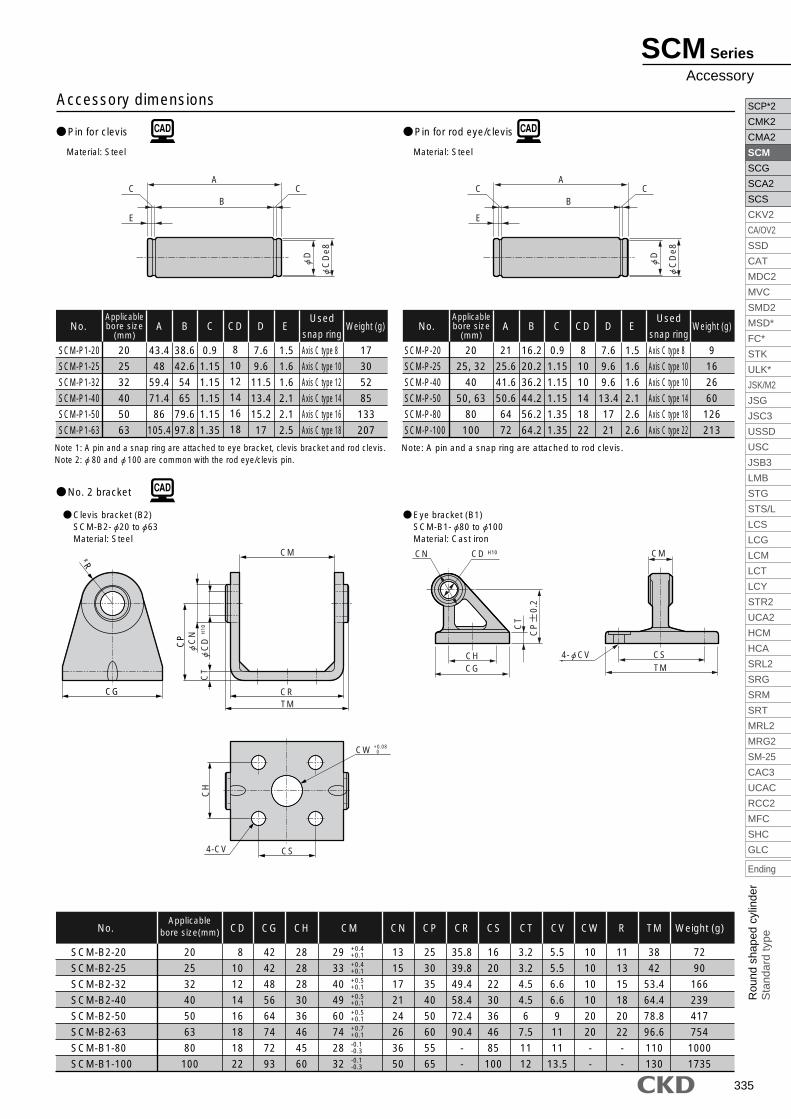
335
SCP*2
CMK2
CMA2
SCM
SCG
SCA2
SCS
CKV2
CA/OV2
SSD
CAT
MDC2
MVC
SMD2
MSD*
FC*
STK
ULK*
JSK/M2
JSG
JSC3
USSD
USC
JSB3
LMB
STG
STS/L
LCS
LCG
LCM
LCT
LCY
STR2
UCA2
HCM
HCA
SRL2
SRG
SRM
SRT
MRL2
MRG2
SM-25
CAC3
UCAC
RCC2
MFC
SHC
GLC
Ending
Rou
nd s
hape
d cy
linde
rS
tand
ard
type
Material: Steel
SCM-P1-20
SCM-P1-25
SCM-P1-32
SCM-P1-40
SCM-P1-50
SCM-P1-63
20
25
32
40
50
63
43.4
48
59.4
71.4
86
105.4
A
38.6
42.6
54
65
79.6
97.8
B
0.9
1.15
1.15
1.15
1.15
1.35
C
7.6
9.6
11.5
13.4
15.2
17
D
1.5
1.6
1.6
2.1
2.1
2.5
E
17
30
52
85
133
207
Weight (g)
8
10
12
14
16
18
CDNo.Applicablebore size
(mm)
Axis C type 8
Axis C type 10
Axis C type 12
Axis C type 14
Axis C type 16
Axis C type 18
Used
snap ring
SCM-B2-20
SCM-B2-25
SCM-B2-32
SCM-B2-40
SCM-B2-50
SCM-B2-63
SCM-B1-80
SCM-B1-100
20
25
32
40
50
63
80
100
42
42
48
56
64
74
72
93
CG
28
28
28
30
36
46
45
60
CH
8
10
12
14
16
18
18
22
CD
35.8
39.8
49.4
58.4
72.4
90.4
-
-
CR
13
15
17
21
24
26
36
50
CN
72
90
166
239
417
754
1000
1735
Weight (g)
25
30
35
40
50
60
55
65
CP
5.5
5.5
6.6
6.6
9
11
11
13.5
CV
16
20
22
30
36
46
85
100
CS
3.2
3.2
4.5
4.5
6
7.5
11
12
CT
10
10
10
10
20
20
-
-
CW
11
13
15
18
20
22
-
-
R
38
42
53.4
64.4
78.8
96.6
110
130
TMNo.Applicable
bore size(mm)
29
33
40
49
60
74
28
32
CM
Material: Steel
SCM-P-20
SCM-P-25
SCM-P-40
SCM-P-50
SCM-P-80
SCM-P-100
20
25, 32
40
50, 63
80
100
21
25.6
41.6
50.6
64
72
A
16.2
20.2
36.2
44.2
56.2
64.2
B
0.9
1.15
1.15
1.15
1.35
1.35
C
7.6
9.6
9.6
13.4
17
21
D
1.5
1.6
1.6
2.1
2.6
2.6
E
9
16
26
60
126
213
Weight (g)
8
10
10
14
18
22
CDNo.Applicablebore size
(mm)
Axis C type 8
Axis C type 10
Axis C type 10
Axis C type 14
Axis C type 18
Axis C type 22
Used
snap ring
Note: A pin and a snap ring are attached to rod clevis.
Accessory dimensions
+0.4+0.1+0.4+0.1+0.5+0.1+0.5+0.1+0.5+0.1+0.7+0.1-0.1-0.3-0.1-0.3
Pin for clevis
No. 2 bracket
Pin for rod eye/clevis
Clevis bracket (B2)SCM-B2- 20 to 63Material: Steel
Eye bracket (B1)SCM-B1- 80 to 100Material: Cast iron
Note 1: A pin and a snap ring are attached to eye bracket, clevis bracket and rod clevis.Note 2: 80 and 100 are common with the rod eye/clevis pin.
A
B
E
CC
C
De8
D
A
B
E
CC
C
De8
D
CT
CN CD
CHCG
CS
CM
TM
H10
4- CV
CP
0
.2
RRCG
CP
H10
CT
CR
CW
CS4-CV
CH
+0.08
CM
TM
0
C
N
CD
SCM Series
Accessory