SCL Tool Configuration manual - ABB Group files (SCL files). The REF 542plus Protect IT...
132
REF 542plus REF 542plus SCL Tool Configuration manual
Transcript of SCL Tool Configuration manual - ABB Group files (SCL files). The REF 542plus Protect IT...
REF 542plusREF 542plus
SCL Tool
Configuration manual

3
Contents
Copyrights ................................................................................. 5
1. Introduction..............................................................71.1. This manual .............................................................. 71.2. Use of symbols ......................................................... 71.3. Product documentation ............................................... 81.4. Document revisions.................................................... 8
2. Product overview......................................................9
3. IEC 61850 standard ................................................. 11
4. Installation .............................................................134.1. System requirements................................................ 134.2. REF 542plus SCL Tool installation .............................. 134.3. Uninstalling REF 542plus SCL Tool............................. 19
5. SCL files and folders...............................................215.1. 61850 XML File Pool................................................ 215.2. GUIData................................................................. 235.3. Missing Dataset FCDA Entries ................................... 235.4. UserData................................................................ 235.5. Symbol Library ........................................................ 235.6. SCL schema file pool ............................................... 245.7. XML templates ........................................................ 25
6. SCL Tool Components.............................................276.1. SCL GUI ................................................................ 27
6.1.1. Menu bar.................................................... 286.1.2. SCL file generation ...................................... 316.1.3. SCL Import ................................................. 626.1.4. FTP Download/Upload.................................. 90
6.2. SCL core component................................................ 94
7. SCL Tool error and exception handling ................... 1177.1. Missing files........................................................... 1177.2. Configuration Tool RCA file....................................... 1187.3. GUI Validations ..................................................... 118
7.3.1. SCL Generation.......................................... 1187.3.2. SCL Import ................................................1247.3.3. FTP download or upload ..............................125
8. Terminology ......................................................... 127
9. Abbreviations ....................................................... 129
SCL ToolConfiguration manual
REF 542plusREF 542plus1MRS756342
Issued: 30.04.2007Version: A/31.05.2007

4
5
CopyrightsThe information in this document is subject to change without notice and should notbe construed as a commitment by ABB Oy. ABB Oy assumes no responsibility forany errors that may appear in this document.
In no event shall ABB Oy be liable for direct, indirect, special, incidental orconsequential damages of any nature or kind arising from the use of this document,nor shall ABB Oy be liable for incidental or consequential damages arising fromuse of any software or hardware described in this document.
This document and parts thereof must not be reproduced or copied without writtenpermission from ABB Oy, and the contents thereof must not be imparted to a thirdparty nor used for any unauthorized purpose.
The software or hardware described in this document is furnished under a licenseand may be used, copied, or disclosed only in accordance with the terms of suchlicense.
Copyright © 2007 ABB Oy
All rights reserved.
Trademarks
ABB is a registered trademark of ABB Group. All other brand or product namesmentioned in this document may be trademarks or registered trademarks of theirrespective holders.
Guarantee
Please inquire about the terms of guarantee from your nearest ABB representative.
SCL ToolConfiguration manual
REF 542plusREF 542plus1MRS756342

6
7
1. Introduction
1.1. This manual
This manual provides thorough information on the REF 542plus SCL Toolapplication that is used to generate IEC 61850 standard compliant REF 542plusconfiguration files (SCL files). The REF 542plus Protect IT multifunction feederprotection and control unit, henceforth called REF 542plus, can be adapted to theIEC 61850-based substation communication standard to achieve interoperabilitybetween ABB products and the external IEC 61850 world.
In order to achieve this purpose, two major components are required:
* Communication component: Ethernet communication card* IEC 61850 Configuration component: REF 542plus Engineering Tool for the
Ethernet card
The purpose of this document is to describe the SCL Tool features and the user-related activity needed to interact with the SCLTool in order to obtain the SCL files.
User interface, configuration aspects, generation of SCL files and loading of SCLfiles into the Ethernet Board are described in this document. This information isintended for application engineers who are familiar with the REF 542plusengineering methodology and the IEC 61850-6 standard-based terminology andengineering to some extent.
1.2. Use of symbols
This publication includes the following icons that point out safety-related conditionsor other important information:
The information icon alerts the reader to relevant facts and conditions.
It should be understood that operation of damaged equipment could, under certainoperational conditions, result in degraded process performance leading toinformation or property loss. Therefore, comply fully with all notices.
SCL ToolConfiguration manual
REF 542plusREF 542plus1MRS756342
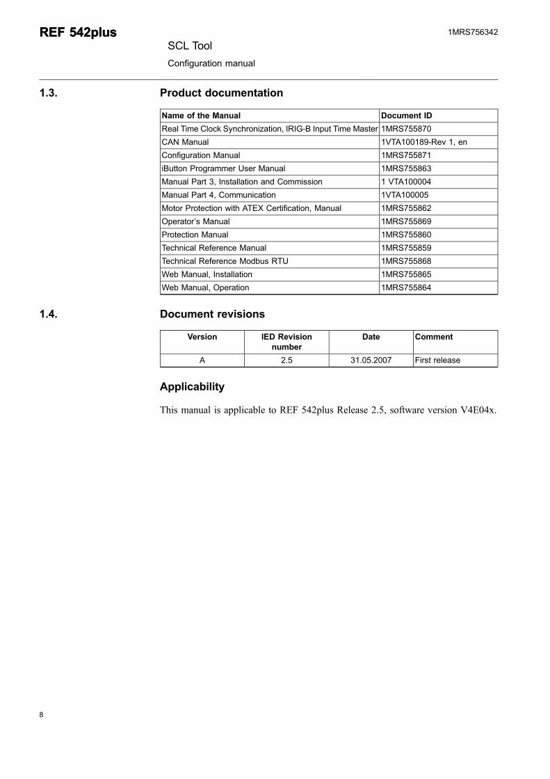
1.3. Product documentation
Name of the Manual Document ID
Real Time Clock Synchronization, IRIG-B Input Time Master 1MRS755870
CAN Manual 1VTA100189-Rev 1, en
Configuration Manual 1MRS755871
iButton Programmer User Manual 1MRS755863
Manual Part 3, Installation and Commission 1 VTA100004
Manual Part 4, Communication 1VTA100005
Motor Protection with ATEX Certification, Manual 1MRS755862
Operator’s Manual 1MRS755869
Protection Manual 1MRS755860
Technical Reference Manual 1MRS755859
Technical Reference Modbus RTU 1MRS755868
Web Manual, Installation 1MRS755865
Web Manual, Operation 1MRS755864
1.4. Document revisions
Version IED Revisionnumber
Date Comment
A 2.5 31.05.2007 First release
Applicability
This manual is applicable to REF 542plus Release 2.5, software version V4E04x.
8
REF 542plusREF 542plusSCL Tool
Configuration manual
1MRS756342
9
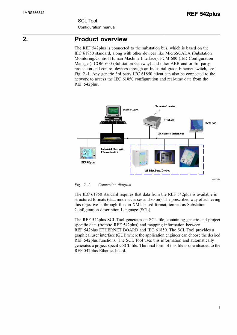
2. Product overviewThe REF 542plus is connected to the substation bus, which is based on theIEC 61850 standard, along with other devices like MicroSCADA (SubstationMonitoring/Control Human Machine Interface), PCM 600 (IED ConfigurationManager), COM 600 (Substation Gateway) and other ABB and or 3rd partyprotection and control devices through an Industrial grade Ethernet switch, seeFig. 2.-1. Any generic 3rd party IEC 61850 client can also be connected to thenetwork to access the IEC 61850 configuration and real-time data from theREF 542plus.
A070199
Fig. 2.-1 Connection diagram
The IEC 61850 standard requires that data from the REF 542plus is available instructured formats (data models/classes and so on). The prescribed way of achievingthis objective is through files in XML-based format, termed as SubstationConfiguration description Language (SCL).
The REF 542plus SCL Tool generates an SCL file, containing generic and projectspecific data (from/to REF 542plus) and mapping information betweenREF 542plus ETHERNET BOARD and IEC 61850. The SCL Tool provides agraphical user interface (GUI) where the application engineer can choose the desiredREF 542plus functions. The SCL Tool uses this information and automaticallygenerates a project specific SCL file. The final form of this file is downloaded to theREF 542plus Ethernet board.
SCL ToolConfiguration manual
REF 542plusREF 542plus1MRS756342

10
11
3. IEC 61850 standardThe IEC 61850 standard defines the communication between the IEDs insubstations.
The IEDs support the following functions:
* Protection and control* Integration of innovative sensor and switch technologies* Metering, supervisory control and data acquisition (SCADA)* Remote monitoring and fault diagnostics* Automated dispatch and control* Asset management* Condition monitoring and diagnostics
IEC 61850 provides:
* Standardized information models for all kinds of protection relays, controllers,disconnectors, earthing switches, circuit breakers, transformers and so on.
* Information exchange methods to access the information model’s data: reportsequences of events, log historical data, control devices, sampled valuedistribution, fast peer-to-peer process data exchange and so on.
* A unified system configuration language (XML-based) and device on-line selfdescription.
Compared to other communication standards for Substation Automation, theIEC 61850 standard defines data modeling and communication services for thisspecific domain. Data modeling is mapped to a communication protocol,Manufacturing Message Specification (MMS, ISO 9506 protocol), which uses TCP/IP and Ethernet. In addition to the communication specifications, engineeringinformation exchange is defined in SCL, which is an XML-based language.
SCL ToolConfiguration manual
REF 542plusREF 542plus1MRS756342

12
13
4. Installation
4.1. System requirements
The system requirements for the SCL Tool are as follows:
* Hardware requirements* Pentium III, 800MHz or higher* 128MB RAM or higher* 13MB free hard disk space
* Software requirements* Operating System: Windows 98/Windows 2000/Windows XP* MSXML 4.0* Microsoft .NET Framework 2.0
The SCL Tool is compatible with the following versions:
* REF 542plus hardware Firmware version 2.5 SP1* REF 542plus Configuration Tool version V4E04x
4.2. REF 542plus SCL Tool installation
Follow these steps to install the SCL Tool:
1. Close all applications.
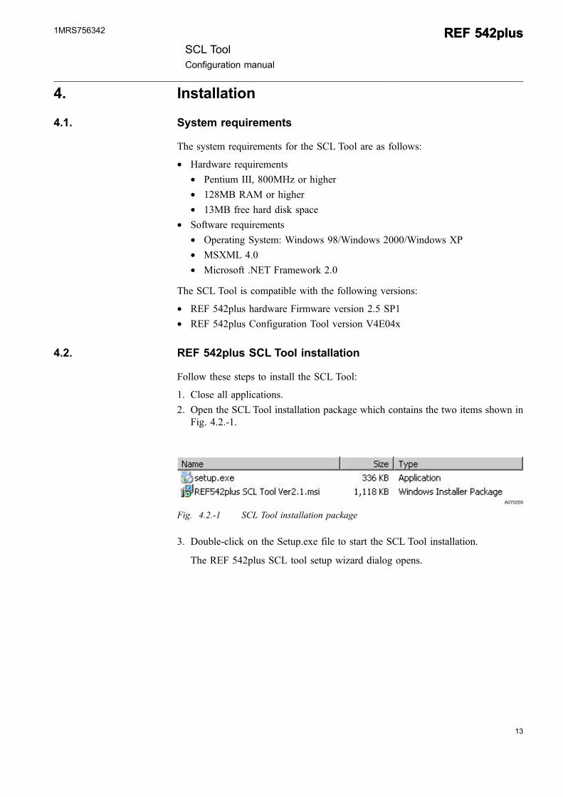
2. Open the SCL Tool installation package which contains the two items shown inFig. 4.2.-1.
A070200
Fig. 4.2.-1 SCL Tool installation package
3. Double-click on the Setup.exe file to start the SCL Tool installation.
The REF 542plus SCL tool setup wizard dialog opens.
SCL ToolConfiguration manual
REF 542plusREF 542plus1MRS756342
A070201
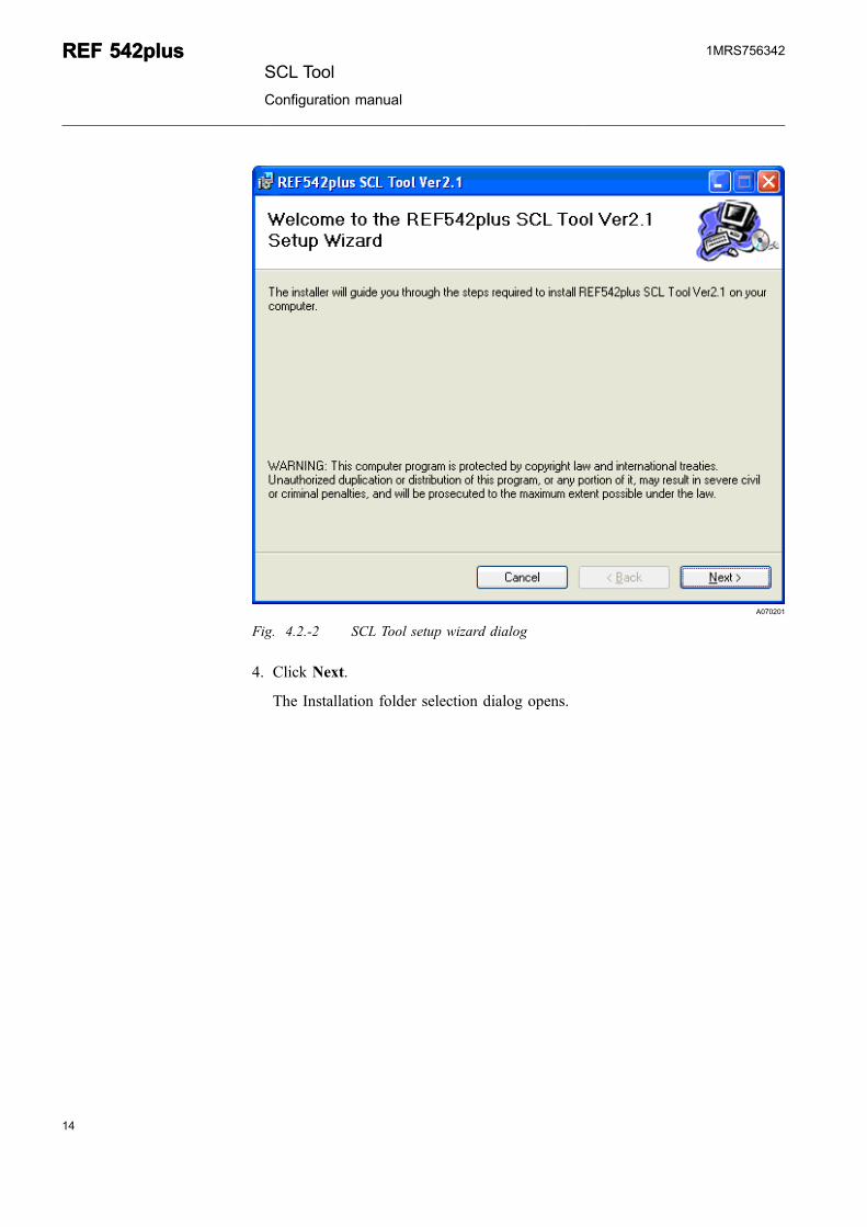
Fig. 4.2.-2 SCL Tool setup wizard dialog
4. Click Next.
The Installation folder selection dialog opens.
14
REF 542plusREF 542plusSCL Tool
Configuration manual
1MRS756342
15
A070202
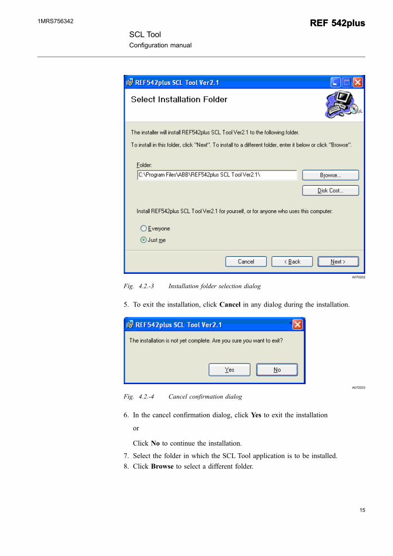
Fig. 4.2.-3 Installation folder selection dialog
5. To exit the installation, click Cancel in any dialog during the installation.
A070203
Fig. 4.2.-4 Cancel confirmation dialog
6. In the cancel confirmation dialog, click Yes to exit the installation
or
Click No to continue the installation.
7. Select the folder in which the SCL Tool application is to be installed.
8. Click Browse to select a different folder.
SCL ToolConfiguration manual
REF 542plusREF 542plus1MRS756342
A070204
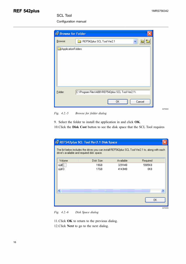
Fig. 4.2.-5 Browse for folder dialog
9. Select the folder to install the application in and click OK.
10.Click the Disk Cost button to see the disk space that the SCL Tool requires
A070205
Fig. 4.2.-6 Disk Space dialog
11.Click OK to return to the previous dialog.
12.Click Next to go to the next dialog.
16
REF 542plusREF 542plusSCL Tool
Configuration manual
1MRS756342
17
A070206
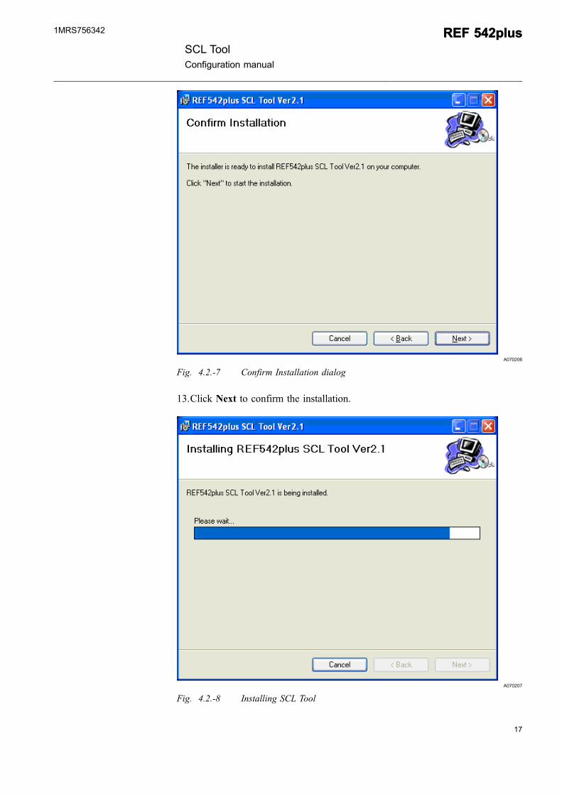
Fig. 4.2.-7 Confirm Installation dialog
13.Click Next to confirm the installation.
A070207
Fig. 4.2.-8 Installing SCL Tool
SCL ToolConfiguration manual
REF 542plusREF 542plus1MRS756342
A070208
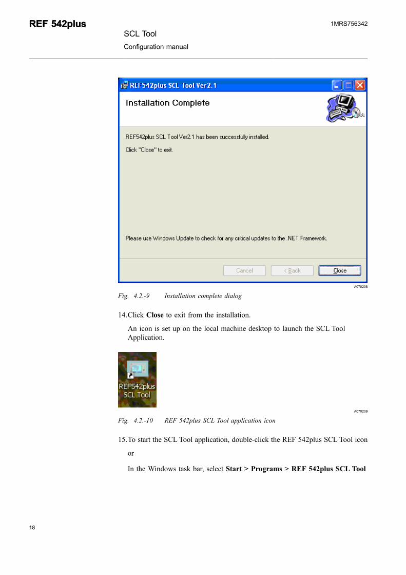
Fig. 4.2.-9 Installation complete dialog
14.Click Close to exit from the installation.
An icon is set up on the local machine desktop to launch the SCL ToolApplication.
A070209
Fig. 4.2.-10 REF 542plus SCL Tool application icon
15.To start the SCL Tool application, double-click the REF 542plus SCL Tool icon
or
In the Windows task bar, select Start > Programs > REF 542plus SCL Tool
18
REF 542plusREF 542plusSCL Tool
Configuration manual
1MRS756342
19
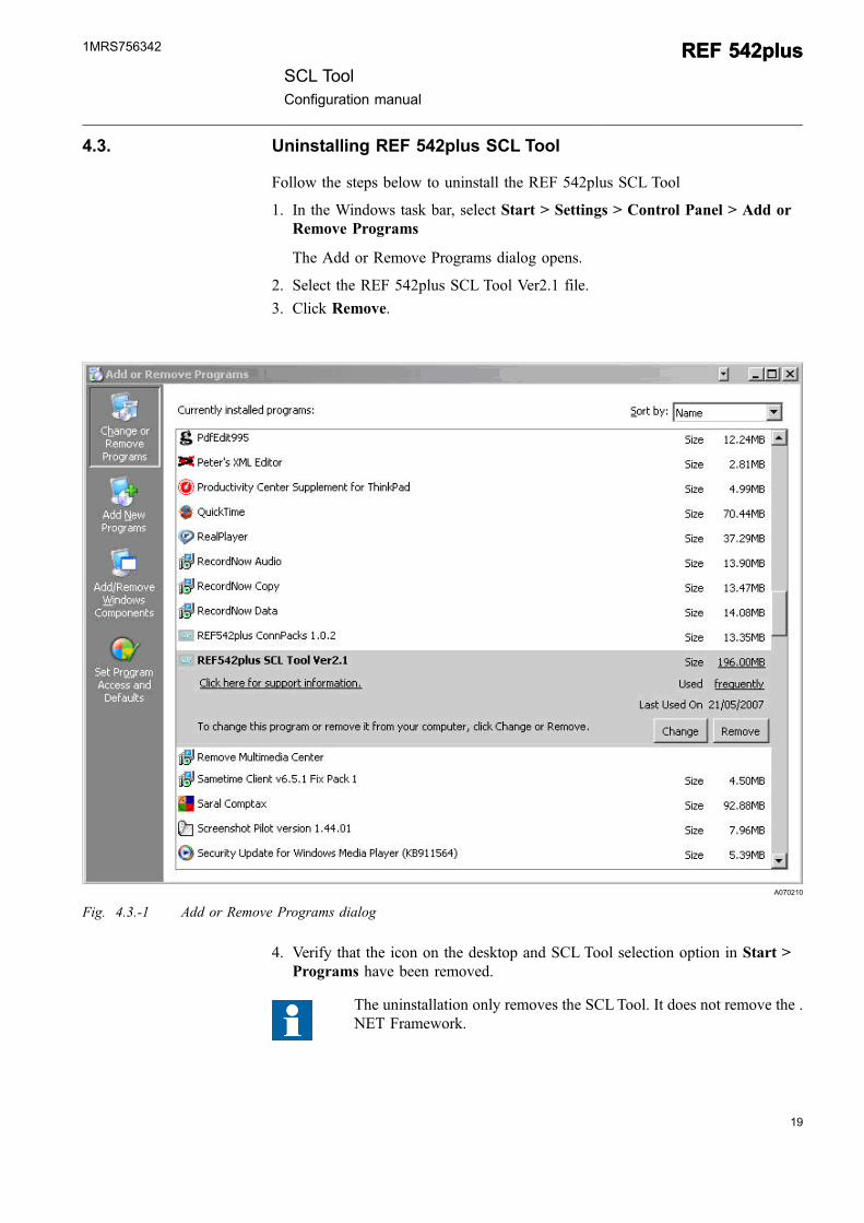
4.3. Uninstalling REF 542plus SCL Tool
Follow the steps below to uninstall the REF 542plus SCL Tool
1. In the Windows task bar, select Start > Settings > Control Panel > Add orRemove Programs
The Add or Remove Programs dialog opens.
2. Select the REF 542plus SCL Tool Ver2.1 file.
3. Click Remove.
A070210
Fig. 4.3.-1 Add or Remove Programs dialog
4. Verify that the icon on the desktop and SCL Tool selection option in Start >Programs have been removed.
The uninstallation only removes the SCLTool. It does not remove the .NET Framework.
SCL ToolConfiguration manual
REF 542plusREF 542plus1MRS756342

20
21
5. SCL files and foldersSome of the critical folders and files that get installed by the SCL Tool installationwizard are listed and described in the following.
5.1. 61850 XML File Pool
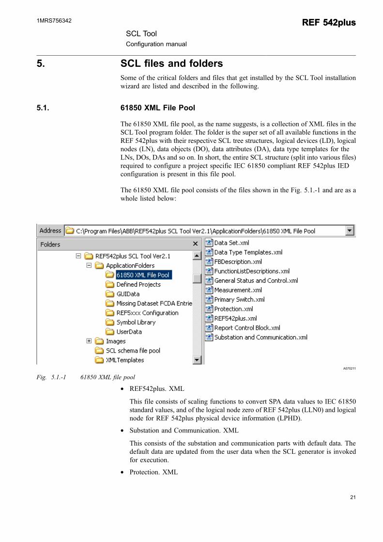
The 61850 XML file pool, as the name suggests, is a collection of XML files in theSCLTool program folder. The folder is the super set of all available functions in theREF 542plus with their respective SCL tree structures, logical devices (LD), logicalnodes (LN), data objects (DO), data attributes (DA), data type templates for theLNs, DOs, DAs and so on. In short, the entire SCL structure (split into various files)required to configure a project specific IEC 61850 compliant REF 542plus IEDconfiguration is present in this file pool.
The 61850 XML file pool consists of the files shown in the Fig. 5.1.-1 and are as awhole listed below:
A070211
Fig. 5.1.-1 61850 XML file pool
* REF542plus. XML
This file consists of scaling functions to convert SPA data values to IEC 61850standard values, and of the logical node zero of REF 542plus (LLN0) and logicalnode for REF 542plus physical device information (LPHD).
* Substation and Communication. XML
This consists of the substation and communication parts with default data. Thedefault data are updated from the user data when the SCL generator is invokedfor execution.
* Protection. XML
SCL ToolConfiguration manual
REF 542plusREF 542plus1MRS756342
This file consists of all LNs designated for protection functions with SPA (SPA-OPC server modeling) address mapping. All standard data is allocated to LNs asper the IEC 61850 standard. Additional information from protection functionsare mapped to LN GGIOs.
* Measurement. XML
This consists of all probable measurement DOIs in a REF 542plus device. TheseDOIs (filtered and based on the configuration information in the .rca file) areadded to the Measurement LN MMXU with filtering attributes.
* Primary Switch. XML
This consists of typical LNs for Primary Switch functions like Interlocking open/close (LN CILO), for control/no control (LN CSWI), for Disconnector / EarthSwitch (LN XSWI), for Circuit Breaker (LN XCBR). These LNs / DOIs havedefault data that is updated from the user data when the SCL generator isinvoked for execution.
* General Status and Control. XML
This comprises all possible DOIs that can be associated with general I/Ofunctions, allocated under a LN class GGIO (Generic process I/O). The LN/DOIshave default data that is updated from the user data when the SCL generator isinvoked for execution.
* Data Type Templates. XML
This comprises of all possible LNTypes, DOTypes, DATypes, and Enumerationdefinitions for the LNs defined in the above files, except for the General Statusand Control and Measurement functions.
* Data Set. XML
This comprises of data set definitions for measurement and protection functionsbesides the status of protection functions (LNs).
* Report Control Block. XML
This comprises of report control block definitions for all data sets that can beconfigured. The report control block have default parameters that would beupdated from the user data when the SCL generator is invoked for execution.
* FBDescription. XML
This part is not required for the standalone version of the REF 542plus SCLToolbut is required for PCM ConnPack. FB (as configured in FUPLA) referencesalong with their respective Function Group assignment, PCM tree structurenames and the like for protection, measurement, monitoring and controlfunctions along with necessary filtering attributes are defined in the file.
* FunctionListDescriptions. XML
This part too is not required for the standalone version of the REF 542plus SCLTool but is required for PCM ConnPack. For all the FBs defined in theFBDescription. XML file a unique FB reference number is allocated along withnecessary filtering attributes. This FB number reference is also made in the
22
REF 542plusREF 542plusSCL Tool
Configuration manual
1MRS756342
23
Protection.XML, Measurement.XML, Primary Switch.XML and General Statusand Control.XML files.
5.2. GUIData
This folder comprises the Folderpath.xml and Language.xml files. The Folderpath.xml file is used to store the RCA file path information, while the Language.xml fileis used to store the language setting used by the user.
5.3. Missing Dataset FCDA Entries
During the SCL Generation, if the FCDA entries in a dataset exceeds the maximumlimit, the excess FCDA entries are collected into an XML file. This XML file issaved in this folder.
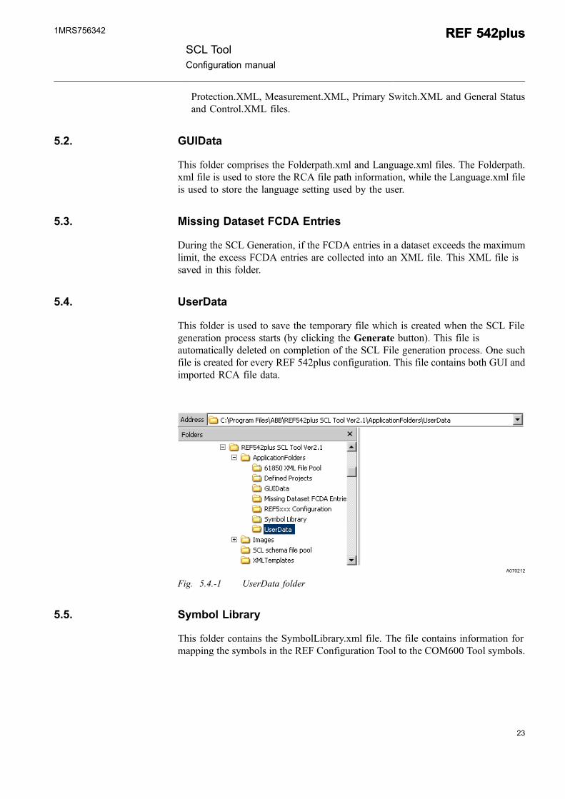
5.4. UserData
This folder is used to save the temporary file which is created when the SCL Filegeneration process starts (by clicking the Generate button). This file isautomatically deleted on completion of the SCL File generation process. One suchfile is created for every REF 542plus configuration. This file contains both GUI andimported RCA file data.
A070212
Fig. 5.4.-1 UserData folder
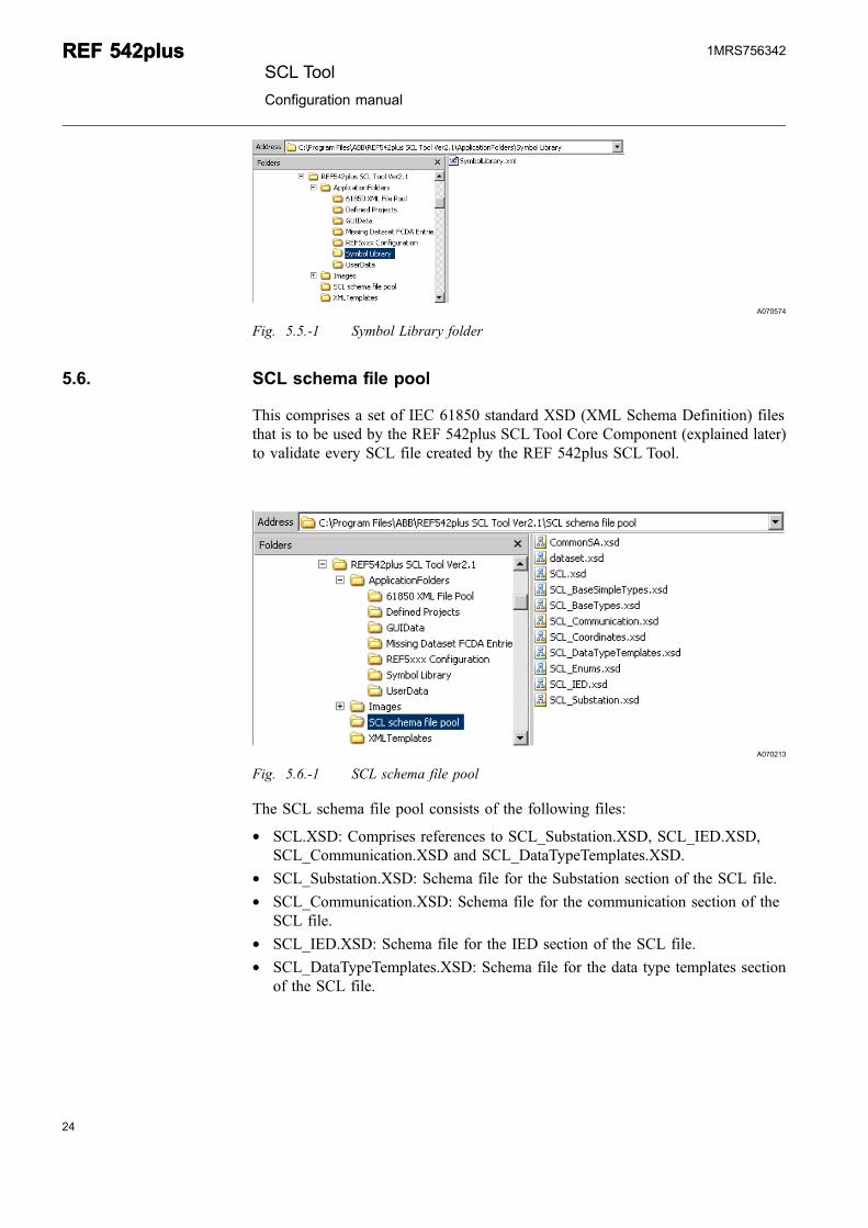
5.5. Symbol Library
This folder contains the SymbolLibrary.xml file. The file contains information formapping the symbols in the REF Configuration Tool to the COM600 Tool symbols.
SCL ToolConfiguration manual
REF 542plusREF 542plus1MRS756342
A070574
Fig. 5.5.-1 Symbol Library folder
5.6. SCL schema file pool
This comprises a set of IEC 61850 standard XSD (XML Schema Definition) filesthat is to be used by the REF 542plus SCL Tool Core Component (explained later)to validate every SCL file created by the REF 542plus SCL Tool.
A070213
Fig. 5.6.-1 SCL schema file pool
The SCL schema file pool consists of the following files:
* SCL.XSD: Comprises references to SCL_Substation.XSD, SCL_IED.XSD,SCL_Communication.XSD and SCL_DataTypeTemplates.XSD.
* SCL_Substation.XSD: Schema file for the Substation section of the SCL file.* SCL_Communication.XSD: Schema file for the communication section of the
SCL file.* SCL_IED.XSD: Schema file for the IED section of the SCL file.* SCL_DataTypeTemplates.XSD: Schema file for the data type templates section
of the SCL file.
24
REF 542plusREF 542plusSCL Tool
Configuration manual
1MRS756342
25
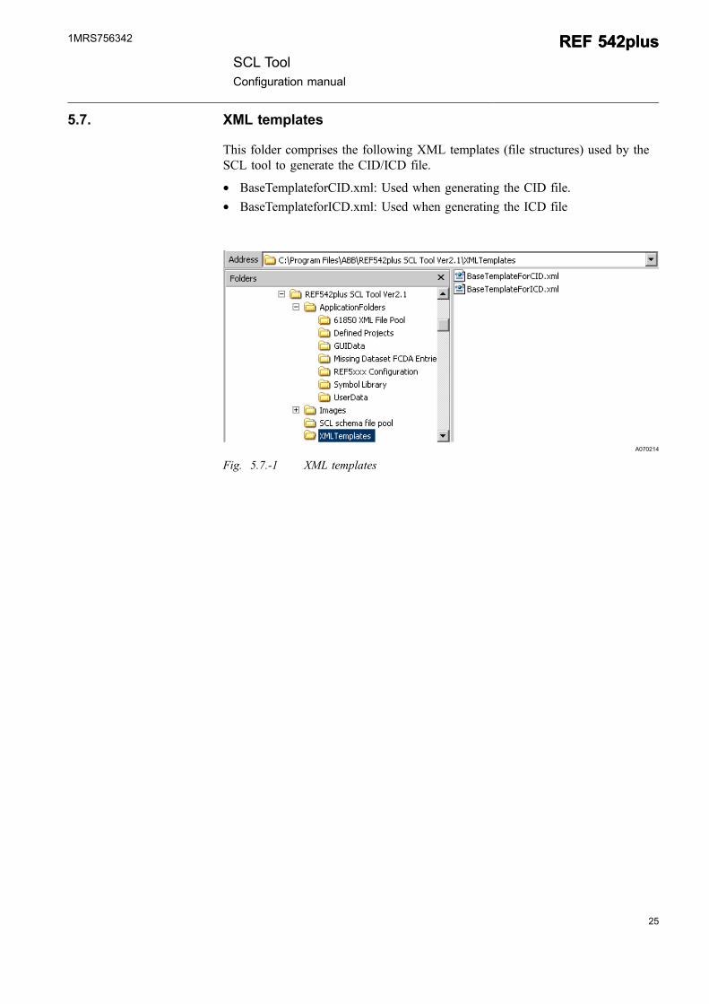
5.7. XML templates
This folder comprises the following XML templates (file structures) used by theSCL tool to generate the CID/ICD file.
* BaseTemplateforCID.xml: Used when generating the CID file.* BaseTemplateforICD.xml: Used when generating the ICD file
A070214
Fig. 5.7.-1 XML templates
SCL ToolConfiguration manual
REF 542plusREF 542plus1MRS756342

26
27
6. SCL Tool ComponentsThe SCL Tool can be divided into two major components:
* SCL GUI* SCL Core Component
6.1. SCL GUI
The GUI component of the SCL Tool contains:
* Menu bar: Composed of five menu items, namely File, View, Tools, Windowand Help
* SCL File Operations Tab strip: Composed of three tabs, namely SCL Generation,SCL Import and FTP Download or Upload.
When double-clicking the application icon on the desktop, the application opens anda window is displayed as shown in Fig. 6.1.-1.
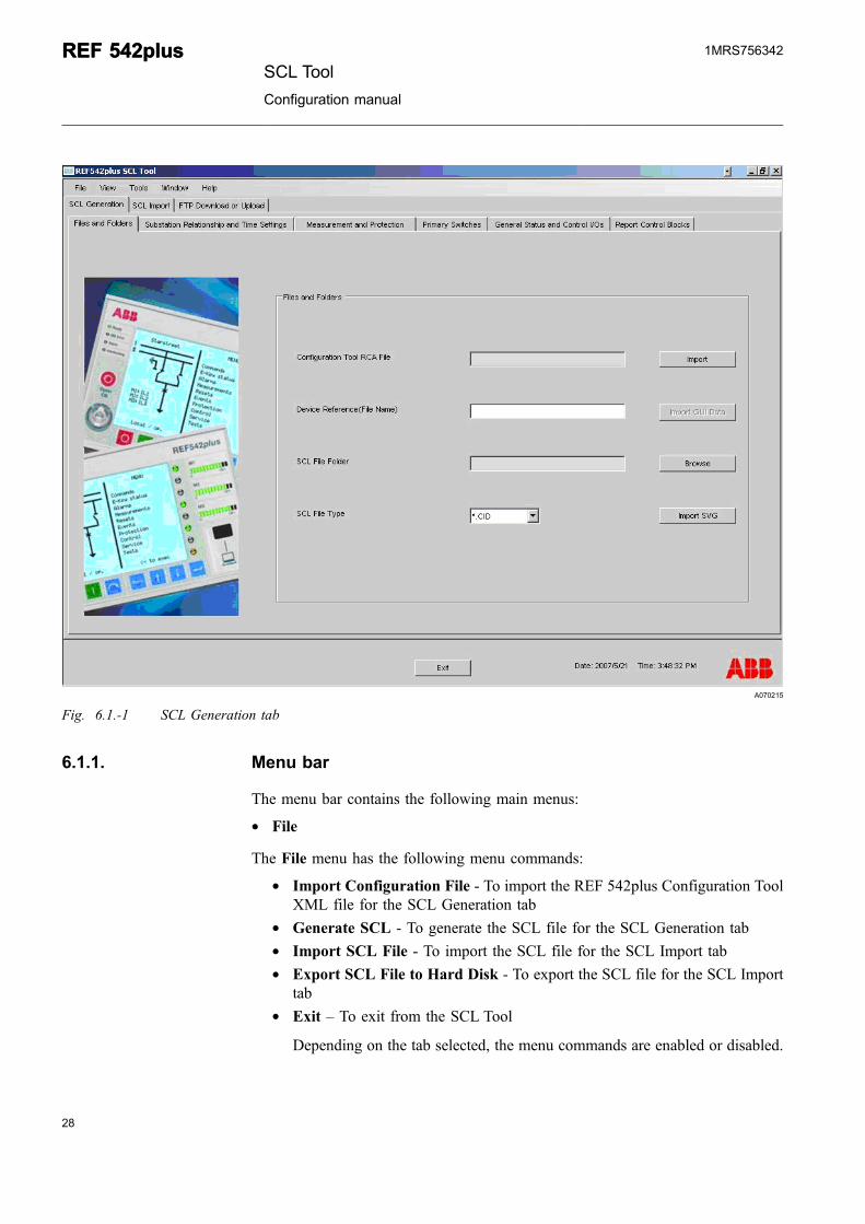
The user can select any one of the three tabs in the SCL File Operations Tab stripdescribed in the following:
* SCL Generation: In this tab, the user can enter the required configurationinformation for the REF device and generate the SCL files. Thus this tab aids inthe creation of an SCL file.
* SCL Import: In this tab, the user can import an existing CID/ICD file, modifyLNs and then export the same to an SCL file. Thus this tab aids in modificationof an SCL file.
* FTP Upload or Download: In this tab, the user can download (move a CID filefrom the system hard disk to the REF 542plus Ethernet board) or upload (move aCID file from the REF 542plus Ethernet board to the system hard disk) via FTP.Thus this tab aids in adding a new configuration file to the Ethernet board orchanging the configuration file already present on the Ethernet board.
By default the SCL Generation tab is selected, see Fig. 6.1.-1.
SCL ToolConfiguration manual
REF 542plusREF 542plus1MRS756342
A070215
Fig. 6.1.-1 SCL Generation tab
6.1.1. Menu bar
The menu bar contains the following main menus:
* File
The File menu has the following menu commands:
* Import Configuration File - To import the REF 542plus Configuration ToolXML file for the SCL Generation tab
* Generate SCL - To generate the SCL file for the SCL Generation tab* Import SCL File - To import the SCL file for the SCL Import tab* Export SCL File to Hard Disk - To export the SCL file for the SCL Import
tab* Exit – To exit from the SCL Tool
Depending on the tab selected, the menu commands are enabled or disabled.
28
REF 542plusREF 542plusSCL Tool
Configuration manual
1MRS756342
29
A070216
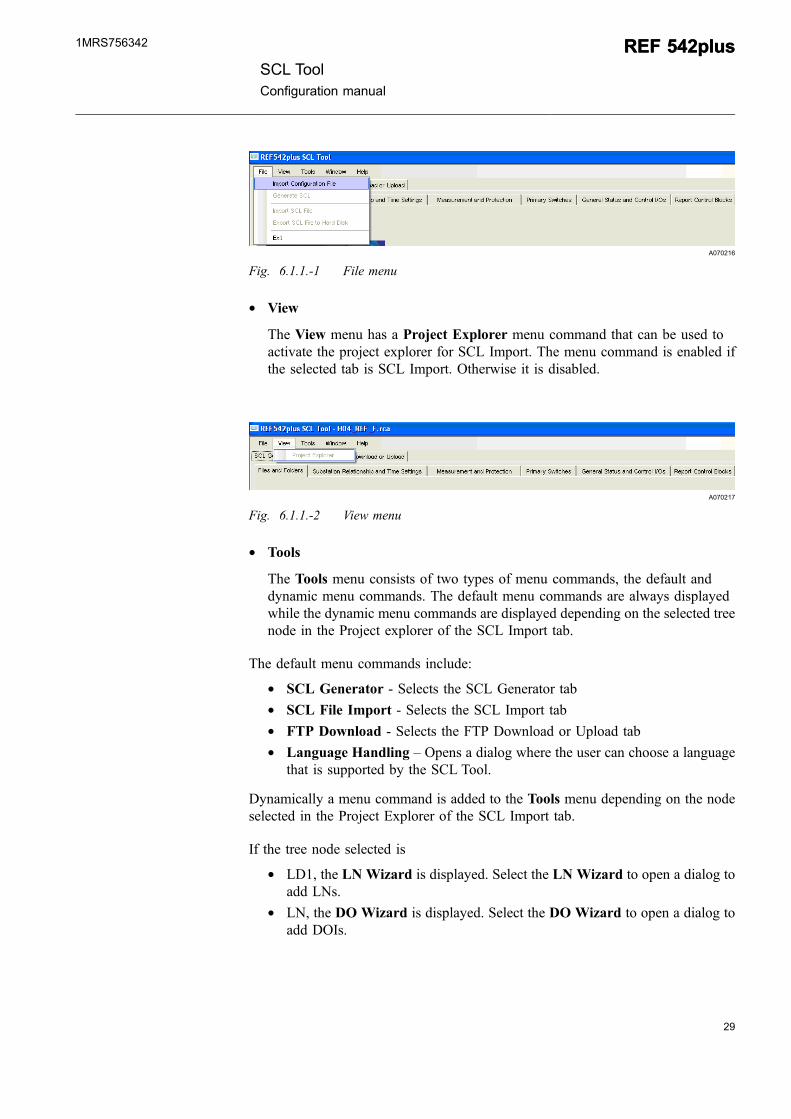
Fig. 6.1.1.-1 File menu
* View
The View menu has a Project Explorer menu command that can be used toactivate the project explorer for SCL Import. The menu command is enabled ifthe selected tab is SCL Import. Otherwise it is disabled.
A070217
Fig. 6.1.1.-2 View menu
* Tools
The Tools menu consists of two types of menu commands, the default anddynamic menu commands. The default menu commands are always displayedwhile the dynamic menu commands are displayed depending on the selected treenode in the Project explorer of the SCL Import tab.
The default menu commands include:
* SCL Generator - Selects the SCL Generator tab* SCL File Import - Selects the SCL Import tab* FTP Download - Selects the FTP Download or Upload tab* Language Handling – Opens a dialog where the user can choose a language
that is supported by the SCL Tool.
Dynamically a menu command is added to the Tools menu depending on the nodeselected in the Project Explorer of the SCL Import tab.
If the tree node selected is
* LD1, the LN Wizard is displayed. Select the LN Wizard to open a dialog toadd LNs.
* LN, the DO Wizard is displayed. Select the DO Wizard to open a dialog toadd DOIs.
SCL ToolConfiguration manual
REF 542plusREF 542plus1MRS756342
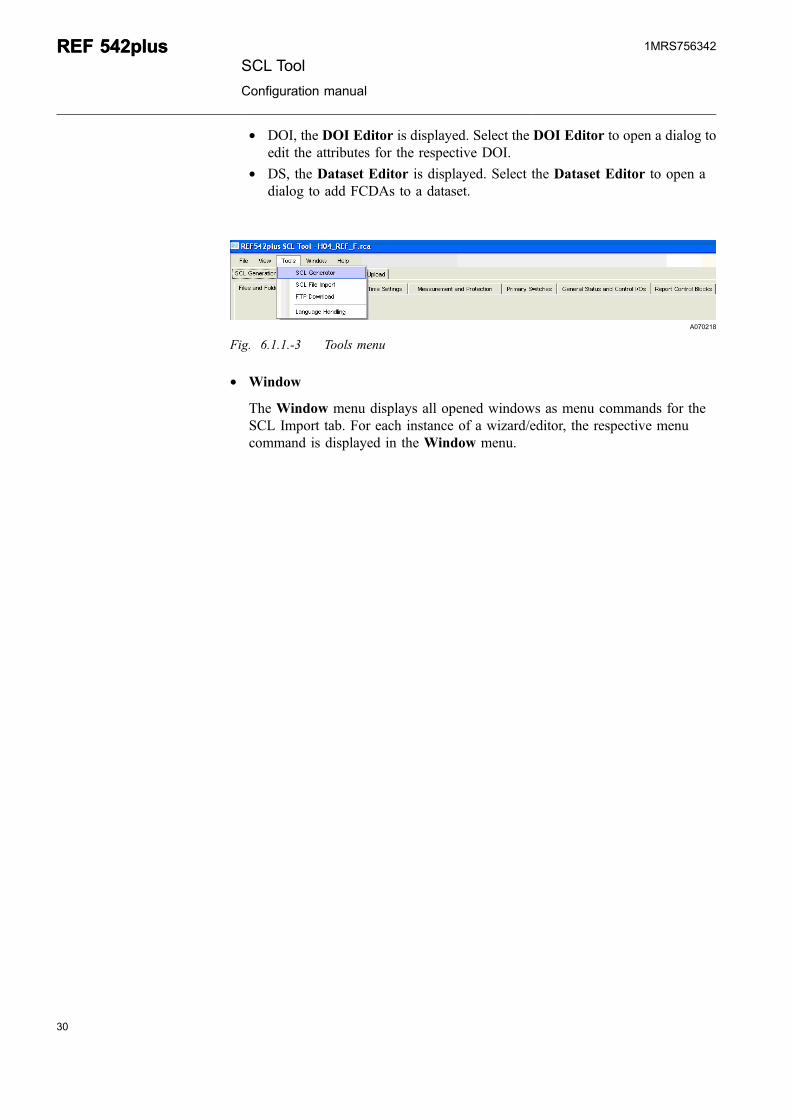
* DOI, the DOI Editor is displayed. Select the DOI Editor to open a dialog toedit the attributes for the respective DOI.
* DS, the Dataset Editor is displayed. Select the Dataset Editor to open adialog to add FCDAs to a dataset.
A070218
Fig. 6.1.1.-3 Tools menu
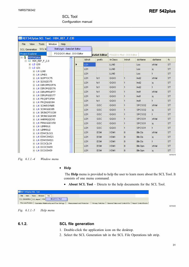
* Window
The Window menu displays all opened windows as menu commands for theSCL Import tab. For each instance of a wizard/editor, the respective menucommand is displayed in the Window menu.
30
REF 542plusREF 542plusSCL Tool
Configuration manual
1MRS756342
31
A070219
Fig. 6.1.1.-4 Window menu
* Help
The Help menu is provided to help the user to learn more about the SCLTool. Itconsists of one menu command.
* About SCL Tool – Directs to the help documents for the SCL Tool.
A070220
Fig. 6.1.1.-5 Help menu
6.1.2. SCL file generation
1. Double-click the application icon on the desktop.
2. Select the SCL Generation tab in the SCL File Operations tab strip.
SCL ToolConfiguration manual
REF 542plusREF 542plus1MRS756342
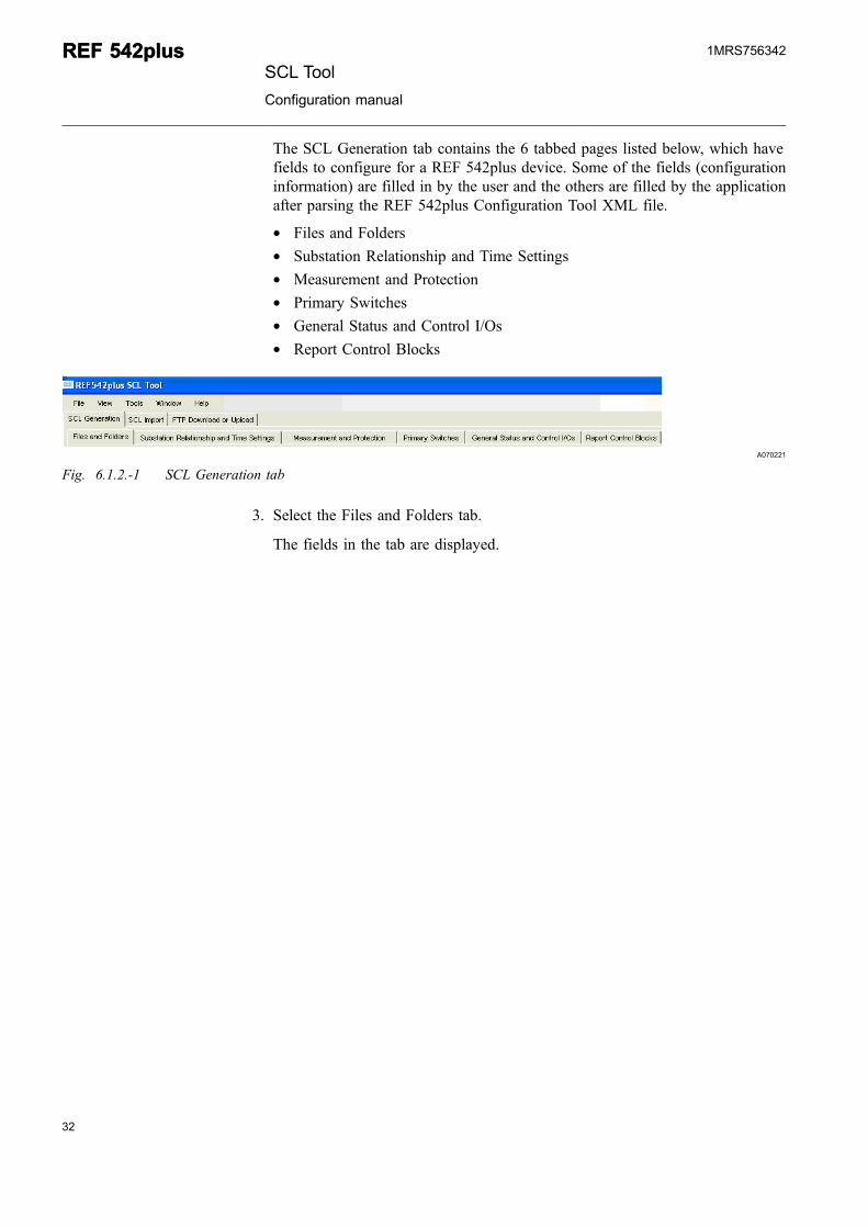
The SCL Generation tab contains the 6 tabbed pages listed below, which havefields to configure for a REF 542plus device. Some of the fields (configurationinformation) are filled in by the user and the others are filled by the applicationafter parsing the REF 542plus Configuration Tool XML file.
* Files and Folders* Substation Relationship and Time Settings* Measurement and Protection* Primary Switches* General Status and Control I/Os* Report Control Blocks
A070221
Fig. 6.1.2.-1 SCL Generation tab
3. Select the Files and Folders tab.
The fields in the tab are displayed.
32
REF 542plusREF 542plusSCL Tool
Configuration manual
1MRS756342
33
A070222
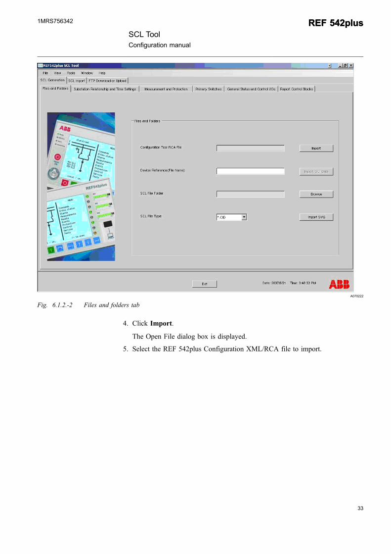
Fig. 6.1.2.-2 Files and folders tab
4. Click Import.
The Open File dialog box is displayed.
5. Select the REF 542plus Configuration XML/RCA file to import.
SCL ToolConfiguration manual
REF 542plusREF 542plus1MRS756342
A070223
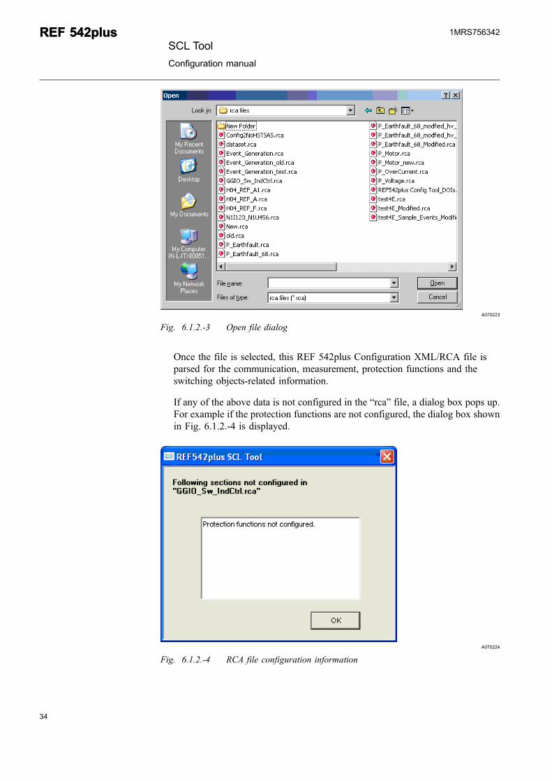
Fig. 6.1.2.-3 Open file dialog
Once the file is selected, this REF 542plus Configuration XML/RCA file isparsed for the communication, measurement, protection functions and theswitching objects-related information.
If any of the above data is not configured in the “rca” file, a dialog box pops up.For example if the protection functions are not configured, the dialog box shownin Fig. 6.1.2.-4 is displayed.
A070224
Fig. 6.1.2.-4 RCA file configuration information
34
REF 542plusREF 542plusSCL Tool
Configuration manual
1MRS756342
35
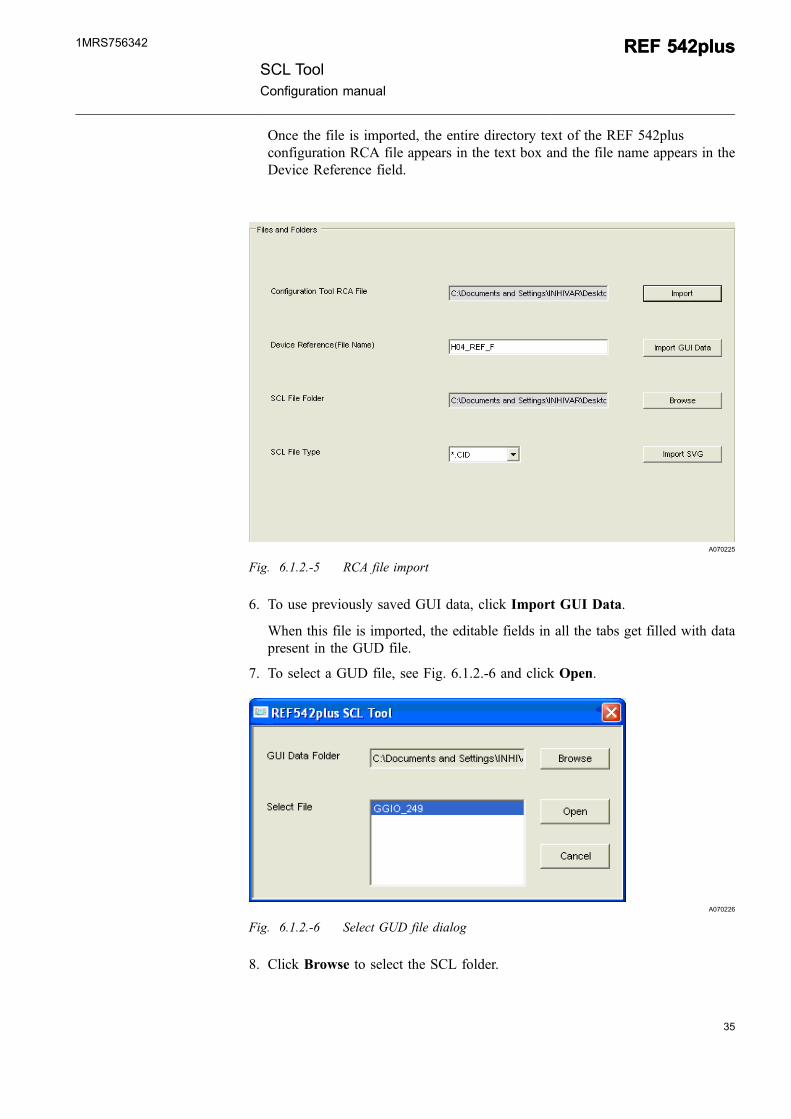
Once the file is imported, the entire directory text of the REF 542plusconfiguration RCA file appears in the text box and the file name appears in theDevice Reference field.
A070225
Fig. 6.1.2.-5 RCA file import
6. To use previously saved GUI data, click Import GUI Data.
When this file is imported, the editable fields in all the tabs get filled with datapresent in the GUD file.
7. To select a GUD file, see Fig. 6.1.2.-6 and click Open.
A070226
Fig. 6.1.2.-6 Select GUD file dialog
8. Click Browse to select the SCL folder.
SCL ToolConfiguration manual
REF 542plusREF 542plus1MRS756342
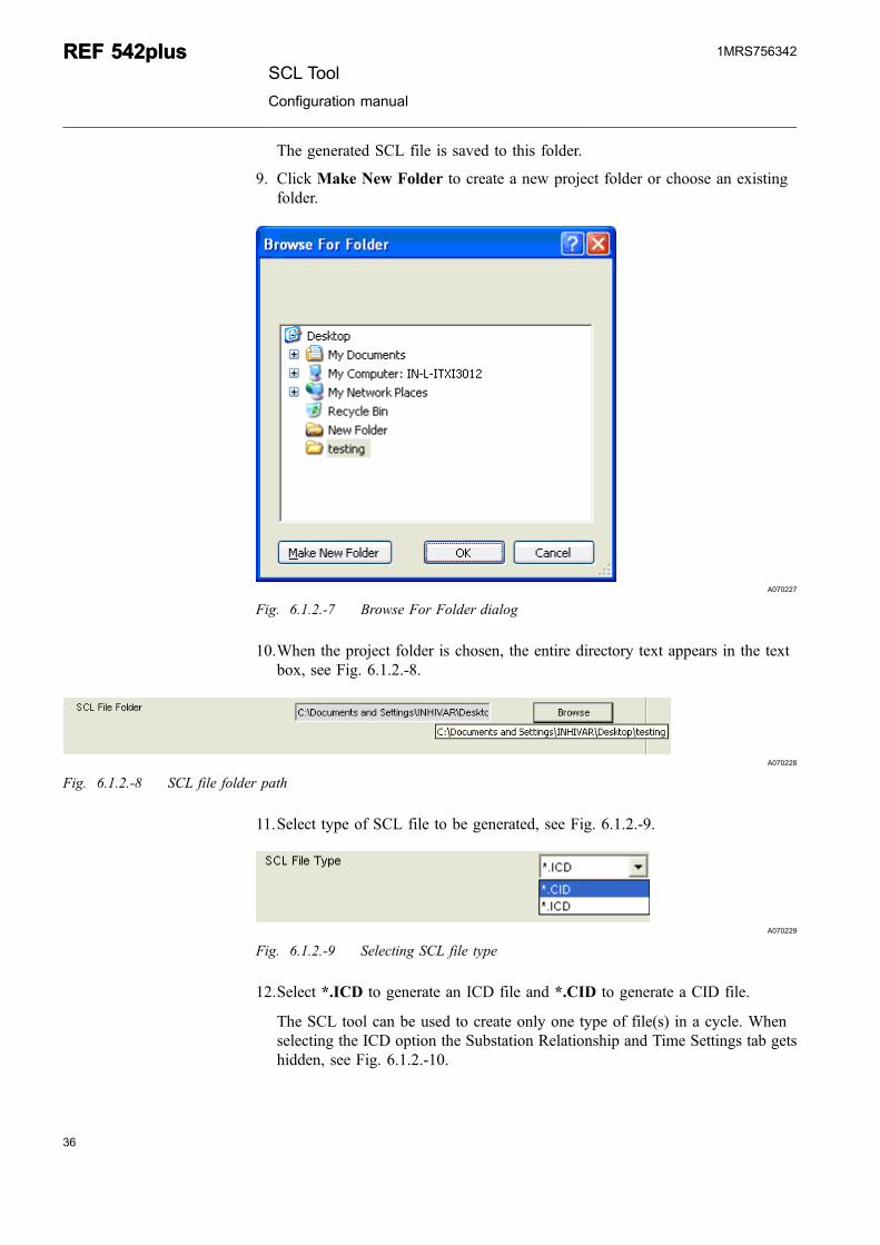
The generated SCL file is saved to this folder.
9. Click Make New Folder to create a new project folder or choose an existingfolder.
A070227
Fig. 6.1.2.-7 Browse For Folder dialog
10.When the project folder is chosen, the entire directory text appears in the textbox, see Fig. 6.1.2.-8.
A070228
Fig. 6.1.2.-8 SCL file folder path
11.Select type of SCL file to be generated, see Fig. 6.1.2.-9.
A070229
Fig. 6.1.2.-9 Selecting SCL file type
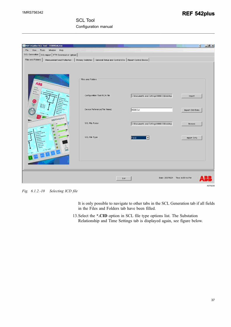
12.Select *.ICD to generate an ICD file and *.CID to generate a CID file.
The SCL tool can be used to create only one type of file(s) in a cycle. Whenselecting the ICD option the Substation Relationship and Time Settings tab getshidden, see Fig. 6.1.2.-10.
36
REF 542plusREF 542plusSCL Tool
Configuration manual
1MRS756342
37
A070230
Fig. 6.1.2.-10 Selecting ICD file
It is only possible to navigate to other tabs in the SCL Generation tab if all fieldsin the Files and Folders tab have been filled.
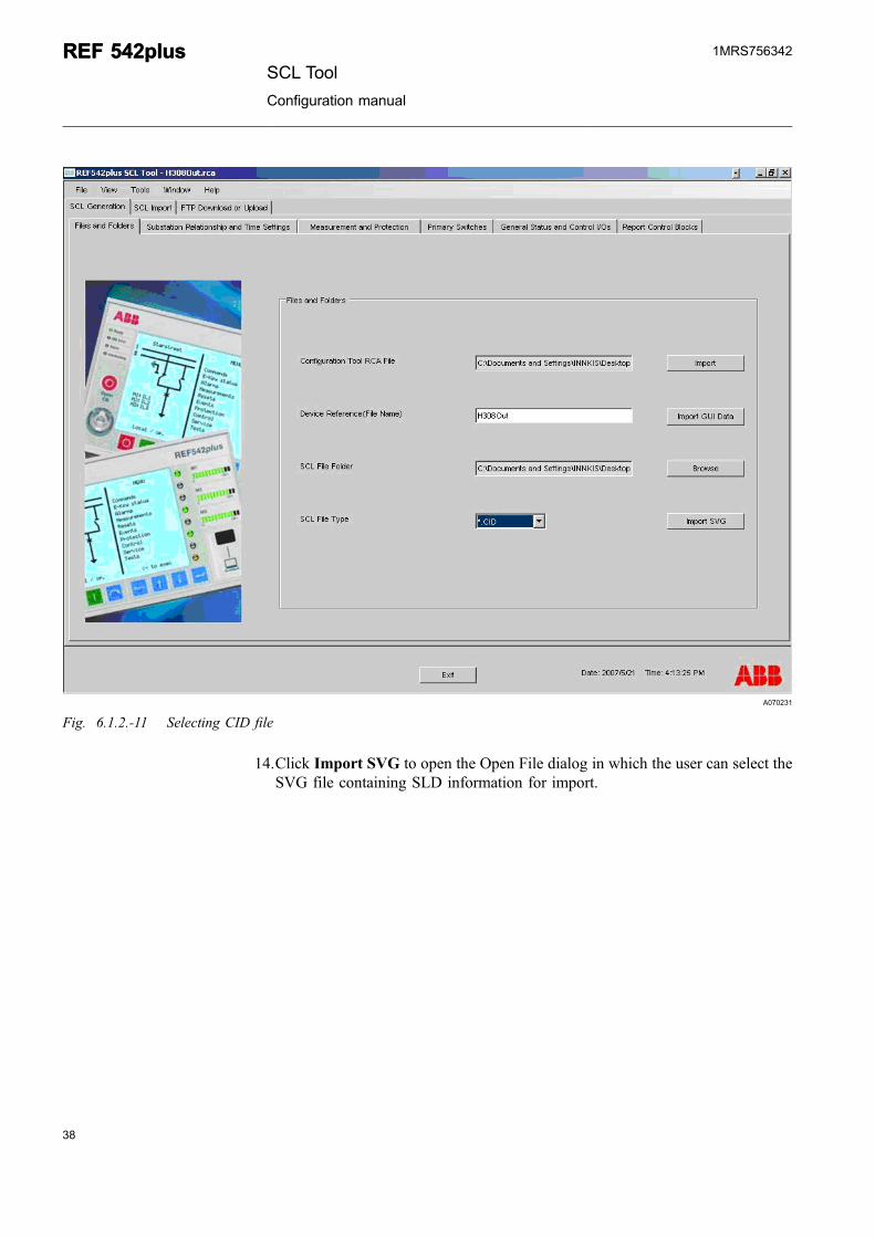
13.Select the *.CID option in SCL file type options list. The SubstationRelationship and Time Settings tab is displayed again, see figure below.
SCL ToolConfiguration manual
REF 542plusREF 542plus1MRS756342
A070231
Fig. 6.1.2.-11 Selecting CID file
14.Click Import SVG to open the Open File dialog in which the user can select theSVG file containing SLD information for import.
38
REF 542plusREF 542plusSCL Tool
Configuration manual
1MRS756342
39
A070556
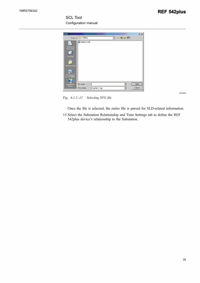
Fig. 6.1.2.-12 Selecting SVG file
Once the file is selected, the entire file is parsed for SLD-related information.
15.Select the Substation Relationship and Time Settings tab to define the REF542plus device’s relationship to the Substation.
SCL ToolConfiguration manual
REF 542plusREF 542plus1MRS756342
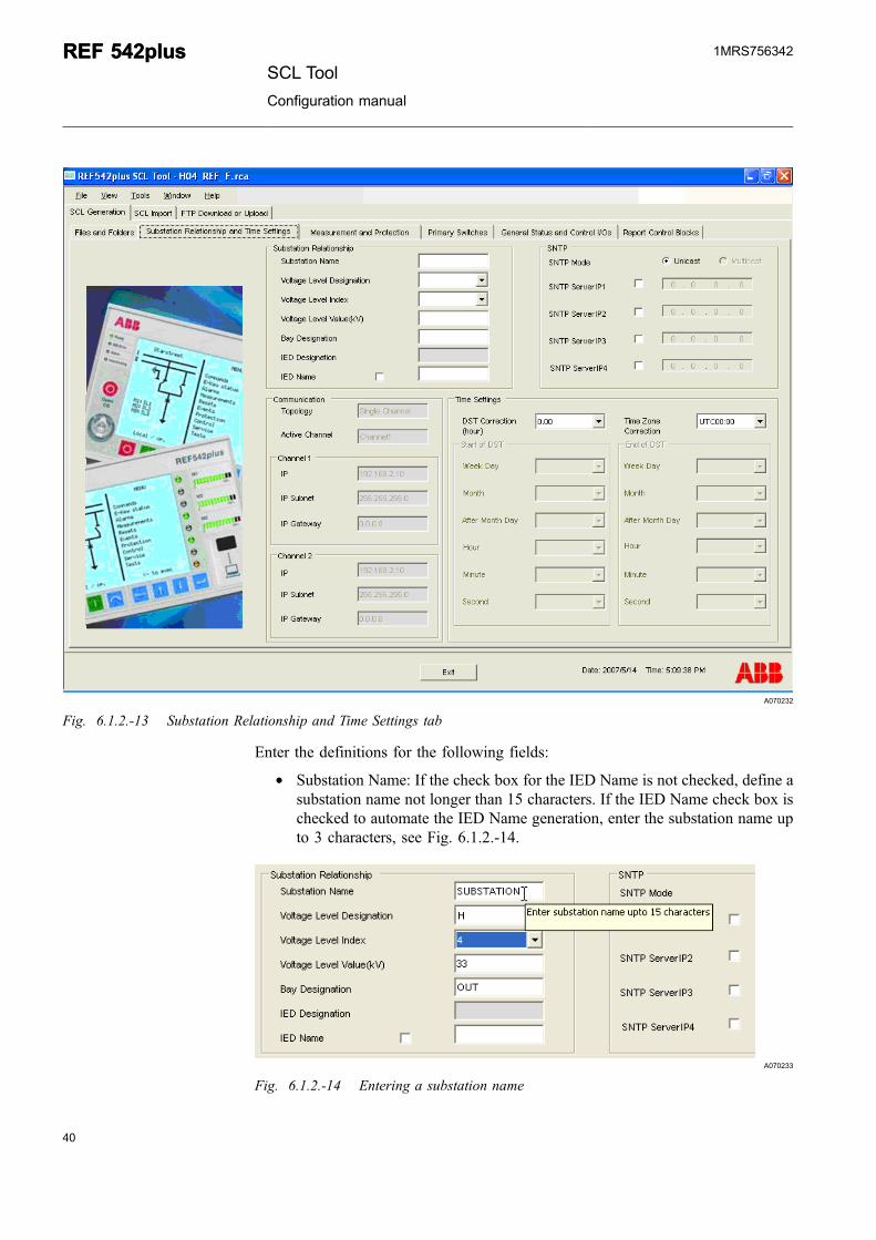
A070232
Fig. 6.1.2.-13 Substation Relationship and Time Settings tab
Enter the definitions for the following fields:
* Substation Name: If the check box for the IED Name is not checked, define asubstation name not longer than 15 characters. If the IED Name check box ischecked to automate the IED Name generation, enter the substation name upto 3 characters, see Fig. 6.1.2.-14.
A070233
Fig. 6.1.2.-14 Entering a substation name
40
REF 542plusREF 542plusSCL Tool
Configuration manual
1MRS756342
41
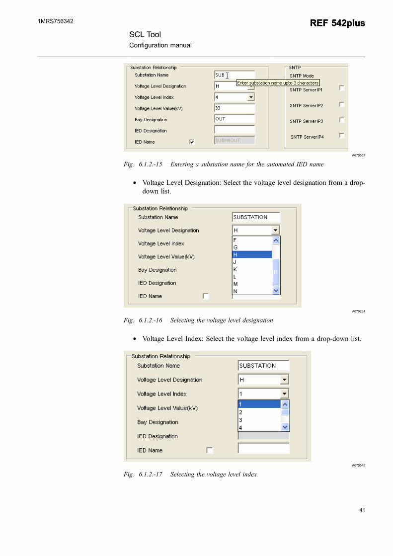
A070557
Fig. 6.1.2.-15 Entering a substation name for the automated IED name
* Voltage Level Designation: Select the voltage level designation from a drop-down list.
A070234
Fig. 6.1.2.-16 Selecting the voltage level designation
* Voltage Level Index: Select the voltage level index from a drop-down list.
A070546
Fig. 6.1.2.-17 Selecting the voltage level index
SCL ToolConfiguration manual
REF 542plusREF 542plus1MRS756342
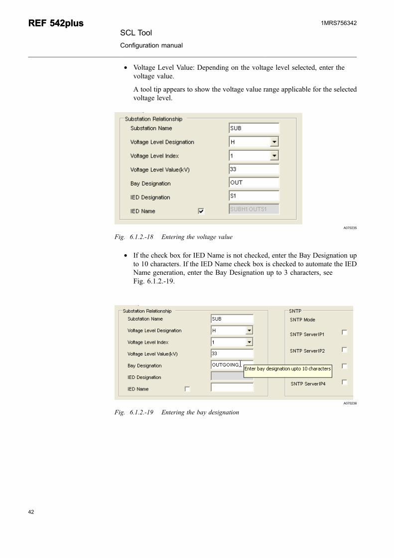
* Voltage Level Value: Depending on the voltage level selected, enter thevoltage value.
A tool tip appears to show the voltage value range applicable for the selectedvoltage level.
A070235
Fig. 6.1.2.-18 Entering the voltage value
* If the check box for IED Name is not checked, enter the Bay Designation upto 10 characters. If the IED Name check box is checked to automate the IEDName generation, enter the Bay Designation up to 3 characters, seeFig. 6.1.2.-19.
A070236
Fig. 6.1.2.-19 Entering the bay designation
42
REF 542plusREF 542plusSCL Tool
Configuration manual
1MRS756342
43
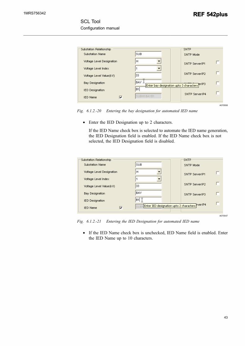
A070558
Fig. 6.1.2.-20 Entering the bay designation for automated IED name
* Enter the IED Designation up to 2 characters.
If the IED Name check box is selected to automate the IED name generation,the IED Designation field is enabled. If the IED Name check box is notselected, the IED Designation field is disabled.
A070547
Fig. 6.1.2.-21 Entering the IED Designation for automated IED name
* If the IED Name check box is unchecked, IED Name field is enabled. Enterthe IED Name up to 10 characters.
SCL ToolConfiguration manual
REF 542plusREF 542plus1MRS756342
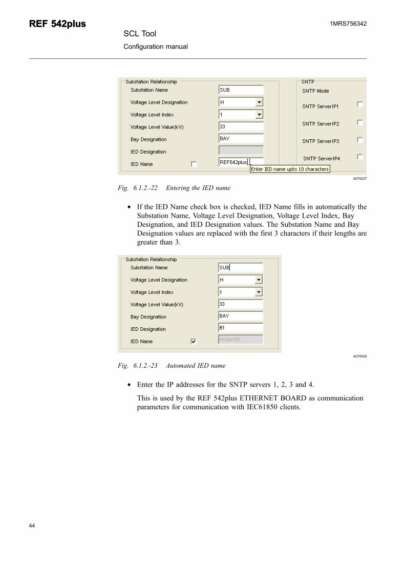
A070237
Fig. 6.1.2.-22 Entering the IED name
* If the IED Name check box is checked, IED Name fills in automatically theSubstation Name, Voltage Level Designation, Voltage Level Index, BayDesignation, and IED Designation values. The Substation Name and BayDesignation values are replaced with the first 3 characters if their lengths aregreater than 3.
A070559
Fig. 6.1.2.-23 Automated IED name
* Enter the IP addresses for the SNTP servers 1, 2, 3 and 4.
This is used by the REF 542plus ETHERNET BOARD as communicationparameters for communication with IEC61850 clients.
44
REF 542plusREF 542plusSCL Tool
Configuration manual
1MRS756342
45
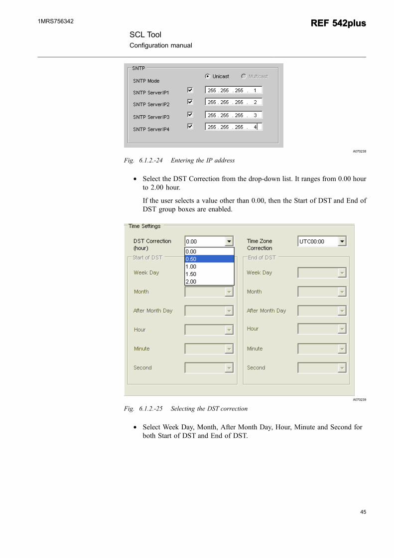
A070238
Fig. 6.1.2.-24 Entering the IP address
* Select the DST Correction from the drop-down list. It ranges from 0.00 hourto 2.00 hour.
If the user selects a value other than 0.00, then the Start of DST and End ofDST group boxes are enabled.
A070239
Fig. 6.1.2.-25 Selecting the DST correction
* Select Week Day, Month, After Month Day, Hour, Minute and Second forboth Start of DST and End of DST.
SCL ToolConfiguration manual
REF 542plusREF 542plus1MRS756342
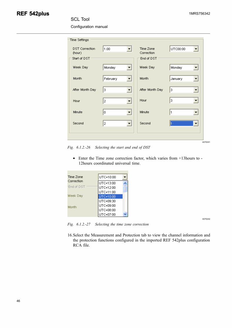
A070241
Fig. 6.1.2.-26 Selecting the start and end of DST
* Enter the Time zone correction factor, which varies from +13hours to -12hours coordinated universal time.
A070242
Fig. 6.1.2.-27 Selecting the time zone correction
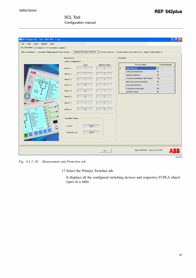
16.Select the Measurement and Protection tab to view the channel information andthe protection functions configured in the imported REF 542plus configurationRCA file.
46
REF 542plusREF 542plusSCL Tool
Configuration manual
1MRS756342
47
A070243
Fig. 6.1.2.-28 Measurement and Protection tab
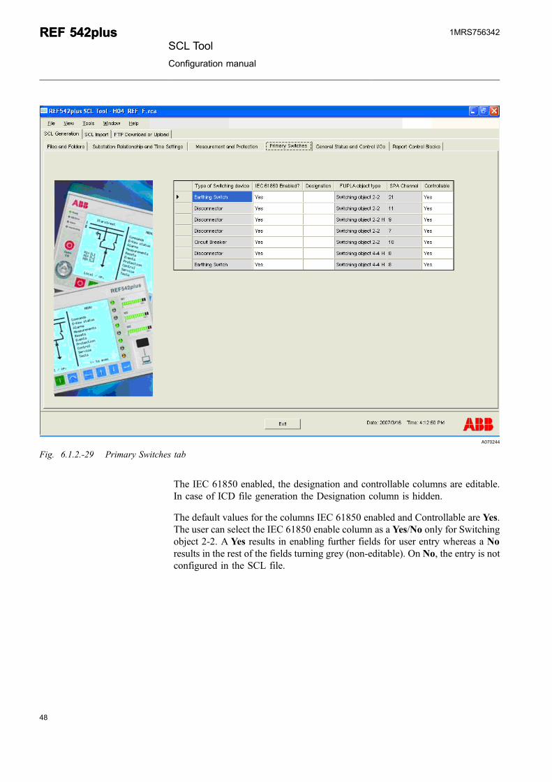
17.Select the Primary Switches tab.
It displays all the configured switching devices and respective FUPLA objecttypes in a table.
SCL ToolConfiguration manual
REF 542plusREF 542plus1MRS756342
A070244
Fig. 6.1.2.-29 Primary Switches tab
The IEC 61850 enabled, the designation and controllable columns are editable.In case of ICD file generation the Designation column is hidden.
The default values for the columns IEC 61850 enabled and Controllable are Yes.The user can select the IEC 61850 enable column as a Yes/No only for Switchingobject 2-2. A Yes results in enabling further fields for user entry whereas a Noresults in the rest of the fields turning grey (non-editable). On No, the entry is notconfigured in the SCL file.
48
REF 542plusREF 542plusSCL Tool
Configuration manual
1MRS756342
49
A070245
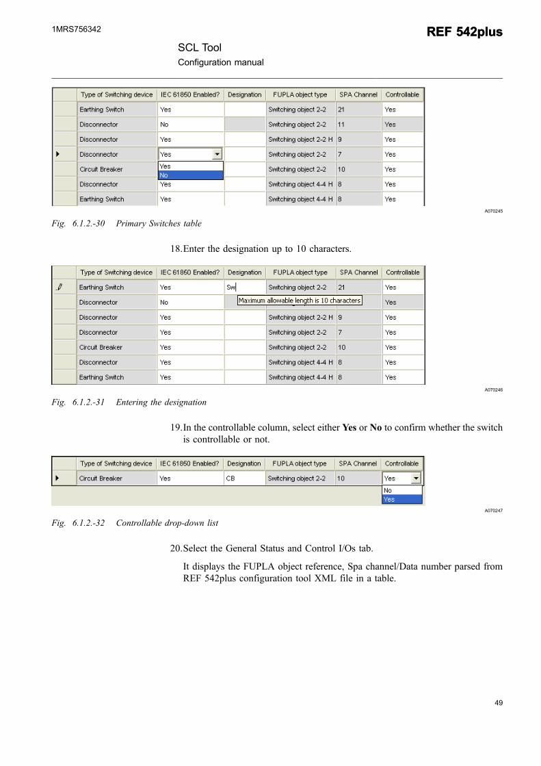
Fig. 6.1.2.-30 Primary Switches table
18.Enter the designation up to 10 characters.
A070246
Fig. 6.1.2.-31 Entering the designation
19.In the controllable column, select either Yes or No to confirm whether the switchis controllable or not.
A070247
Fig. 6.1.2.-32 Controllable drop-down list
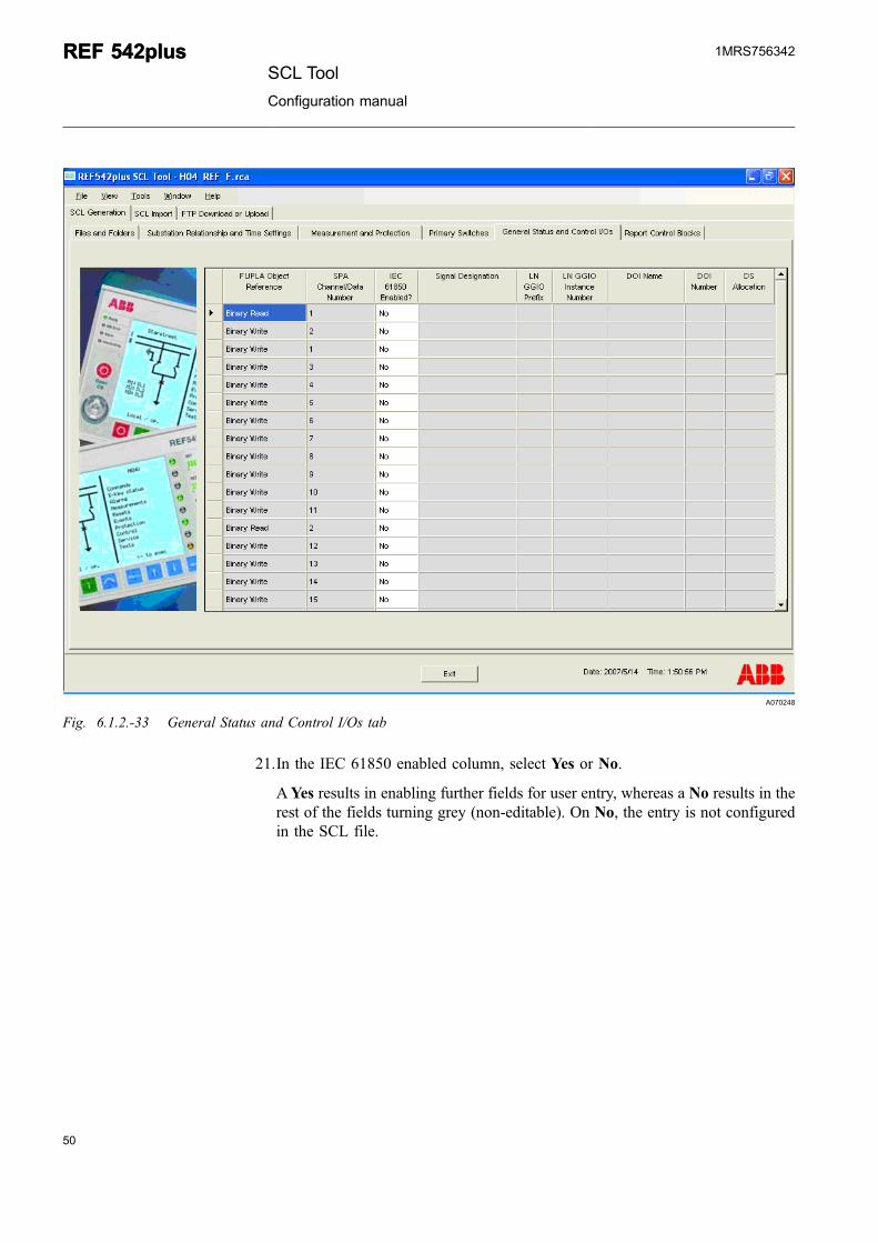
20.Select the General Status and Control I/Os tab.
It displays the FUPLA object reference, Spa channel/Data number parsed fromREF 542plus configuration tool XML file in a table.
SCL ToolConfiguration manual
REF 542plusREF 542plus1MRS756342
A070248
Fig. 6.1.2.-33 General Status and Control I/Os tab
21.In the IEC 61850 enabled column, select Yes or No.
AYes results in enabling further fields for user entry, whereas a No results in therest of the fields turning grey (non-editable). On No, the entry is not configuredin the SCL file.
50
REF 542plusREF 542plusSCL Tool
Configuration manual
1MRS756342
51
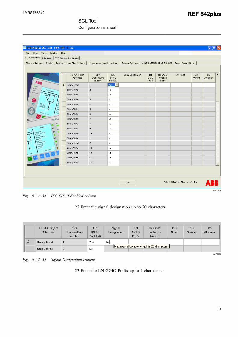
A070249
Fig. 6.1.2.-34 IEC 61850 Enabled column
22.Enter the signal designation up to 20 characters.
A070250
Fig. 6.1.2.-35 Signal Designation column
23.Enter the LN GGIO Prefix up to 4 characters.
SCL ToolConfiguration manual
REF 542plusREF 542plus1MRS756342
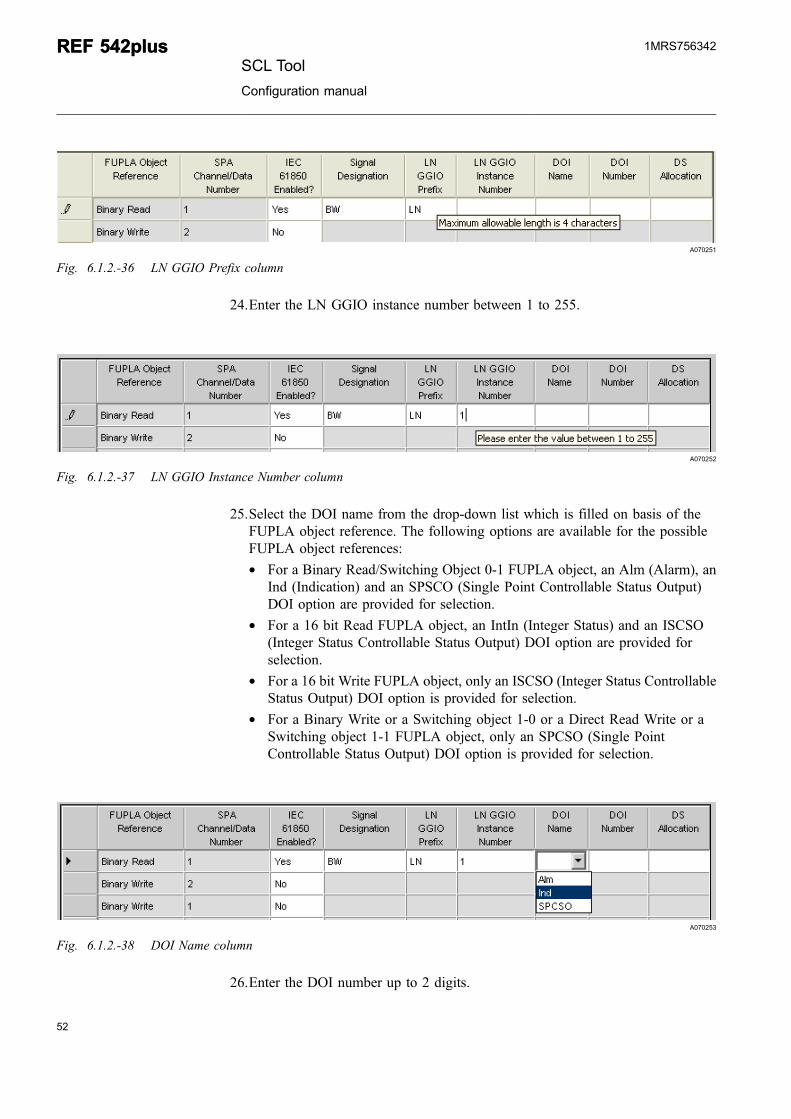
A070251
Fig. 6.1.2.-36 LN GGIO Prefix column
24.Enter the LN GGIO instance number between 1 to 255.
A070252
Fig. 6.1.2.-37 LN GGIO Instance Number column
25.Select the DOI name from the drop-down list which is filled on basis of theFUPLA object reference. The following options are available for the possibleFUPLA object references:* For a Binary Read/Switching Object 0-1 FUPLA object, an Alm (Alarm), an
Ind (Indication) and an SPSCO (Single Point Controllable Status Output)DOI option are provided for selection.
* For a 16 bit Read FUPLA object, an IntIn (Integer Status) and an ISCSO(Integer Status Controllable Status Output) DOI option are provided forselection.
* For a 16 bit Write FUPLA object, only an ISCSO (Integer Status ControllableStatus Output) DOI option is provided for selection.
* For a Binary Write or a Switching object 1-0 or a Direct Read Write or aSwitching object 1-1 FUPLA object, only an SPCSO (Single PointControllable Status Output) DOI option is provided for selection.
A070253
Fig. 6.1.2.-38 DOI Name column
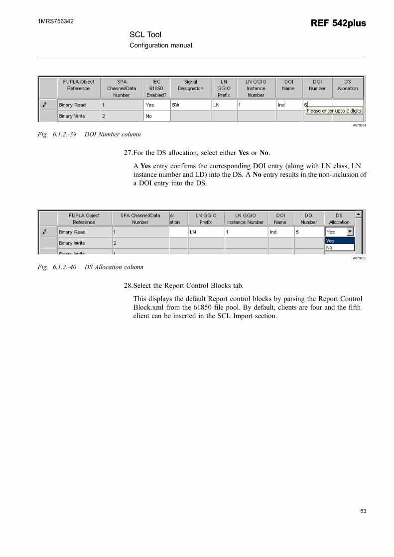
26.Enter the DOI number up to 2 digits.
52
REF 542plusREF 542plusSCL Tool
Configuration manual
1MRS756342
53
A070254
Fig. 6.1.2.-39 DOI Number column
27.For the DS allocation, select either Yes or No.
A Yes entry confirms the corresponding DOI entry (along with LN class, LNinstance number and LD) into the DS. A No entry results in the non-inclusion ofa DOI entry into the DS.
A070255
Fig. 6.1.2.-40 DS Allocation column
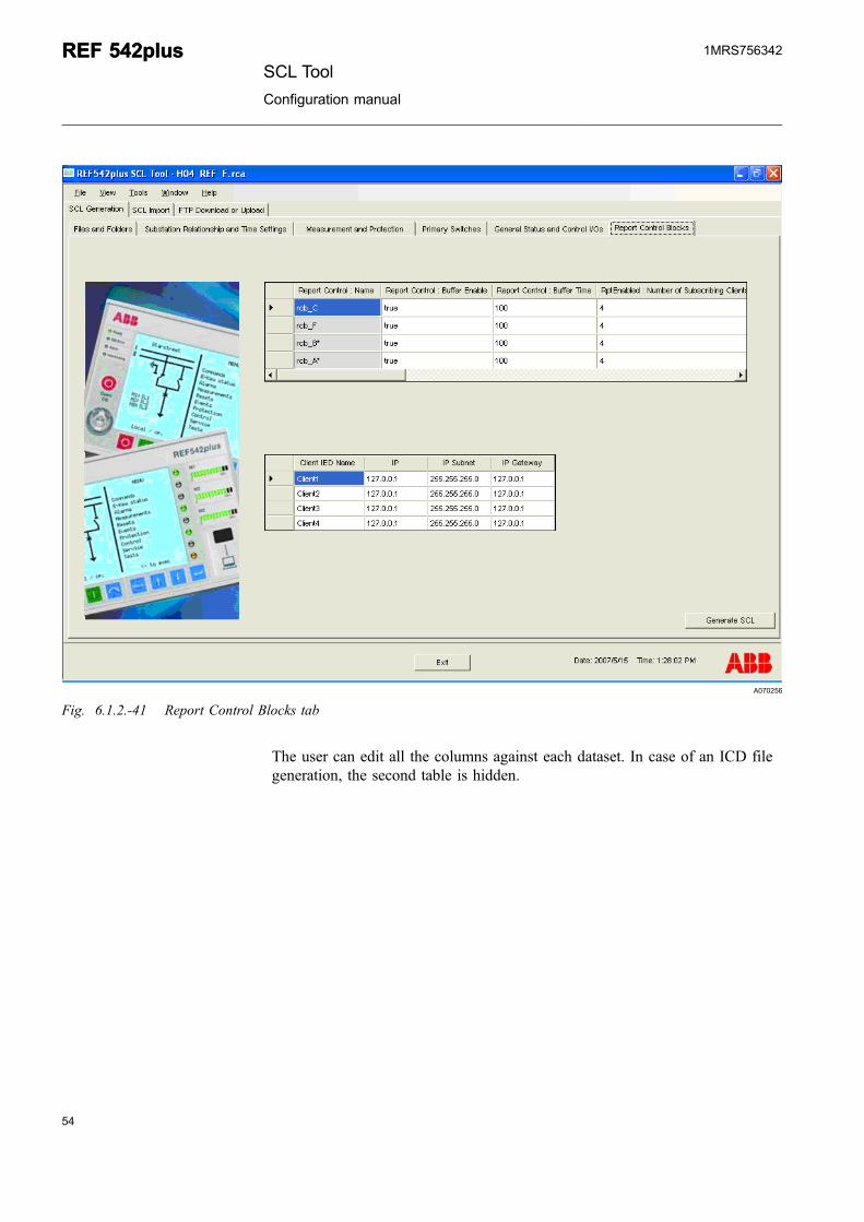
28.Select the Report Control Blocks tab.
This displays the default Report control blocks by parsing the Report ControlBlock.xml from the 61850 file pool. By default, clients are four and the fifthclient can be inserted in the SCL Import section.
SCL ToolConfiguration manual
REF 542plusREF 542plus1MRS756342
A070256
Fig. 6.1.2.-41 Report Control Blocks tab
The user can edit all the columns against each dataset. In case of an ICD filegeneration, the second table is hidden.
54
REF 542plusREF 542plusSCL Tool
Configuration manual
1MRS756342
55
A070257
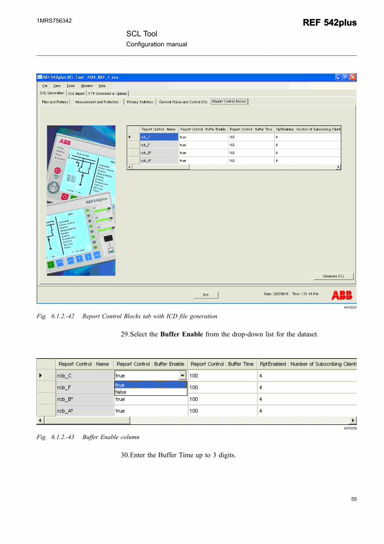
Fig. 6.1.2.-42 Report Control Blocks tab with ICD file generation
29.Select the Buffer Enable from the drop-down list for the dataset.
A070258
Fig. 6.1.2.-43 Buffer Enable column
30.Enter the Buffer Time up to 3 digits.
SCL ToolConfiguration manual
REF 542plusREF 542plus1MRS756342
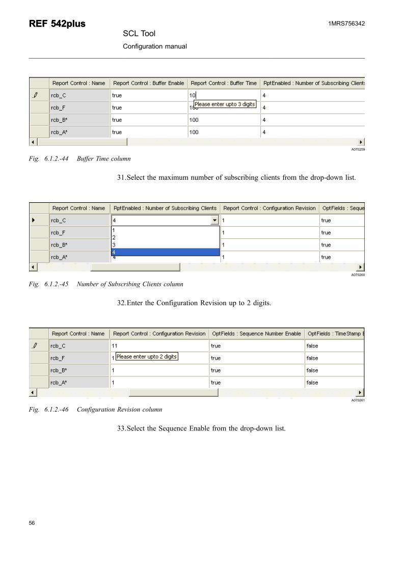
A070259
Fig. 6.1.2.-44 Buffer Time column
31.Select the maximum number of subscribing clients from the drop-down list.
A070260
Fig. 6.1.2.-45 Number of Subscribing Clients column
32.Enter the Configuration Revision up to 2 digits.
A070261
Fig. 6.1.2.-46 Configuration Revision column
33.Select the Sequence Enable from the drop-down list.
56
REF 542plusREF 542plusSCL Tool
Configuration manual
1MRS756342
57
A070262
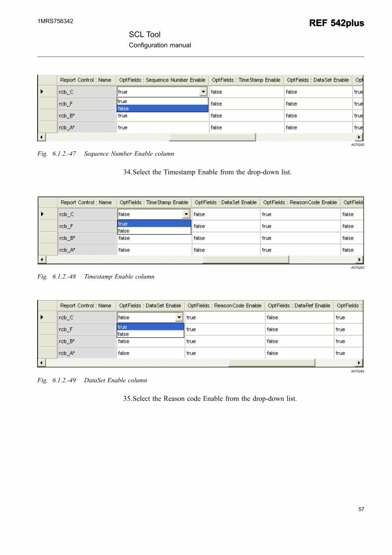
Fig. 6.1.2.-47 Sequence Number Enable column
34.Select the Timestamp Enable from the drop-down list.
A070263
Fig. 6.1.2.-48 Timestamp Enable column
A070264
Fig. 6.1.2.-49 DataSet Enable column
35.Select the Reason code Enable from the drop-down list.
SCL ToolConfiguration manual
REF 542plusREF 542plus1MRS756342
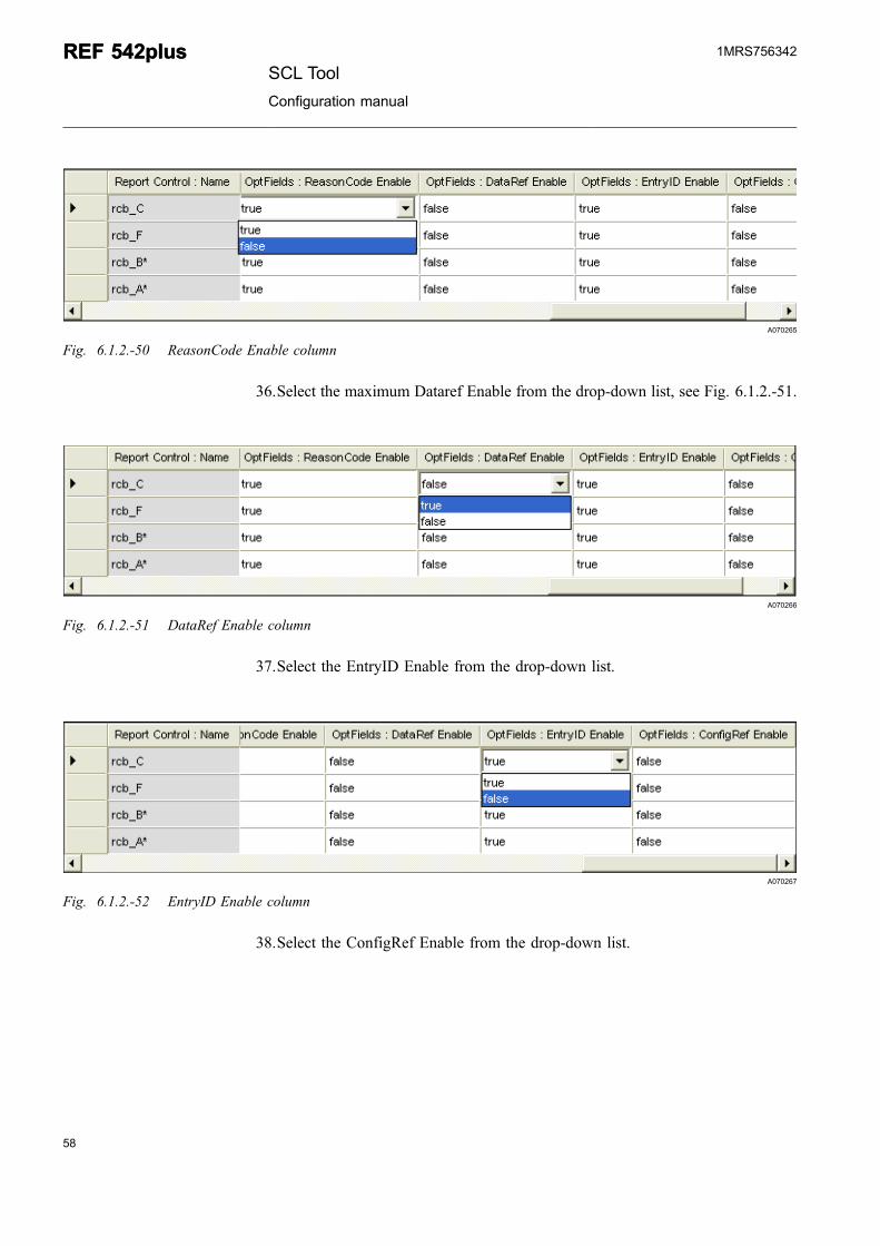
A070265
Fig. 6.1.2.-50 ReasonCode Enable column
36.Select the maximum Dataref Enable from the drop-down list, see Fig. 6.1.2.-51.
A070266
Fig. 6.1.2.-51 DataRef Enable column
37.Select the EntryID Enable from the drop-down list.
A070267
Fig. 6.1.2.-52 EntryID Enable column
38.Select the ConfigRef Enable from the drop-down list.
58
REF 542plusREF 542plusSCL Tool
Configuration manual
1MRS756342
59
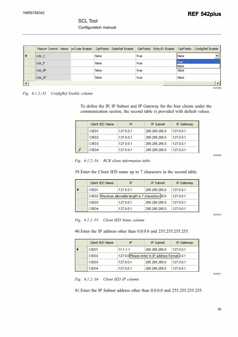
A070268
Fig. 6.1.2.-53 ConfigRef Enable column
To define the IP, IP Subnet and IP Gateway for the four clients under thecommunication section, the second table is provided with default values.
A070269
Fig. 6.1.2.-54 RCB client information table
39.Enter the Client IED name up to 7 characters in the second table.
A070270
Fig. 6.1.2.-55 Client IED Name column
40.Enter the IP address other than 0.0.0.0 and 255.255.255.255.
A070271
Fig. 6.1.2.-56 Client IED IP column
41.Enter the IP Subnet address other than 0.0.0.0 and 255.255.255.255.
SCL ToolConfiguration manual
REF 542plusREF 542plus1MRS756342
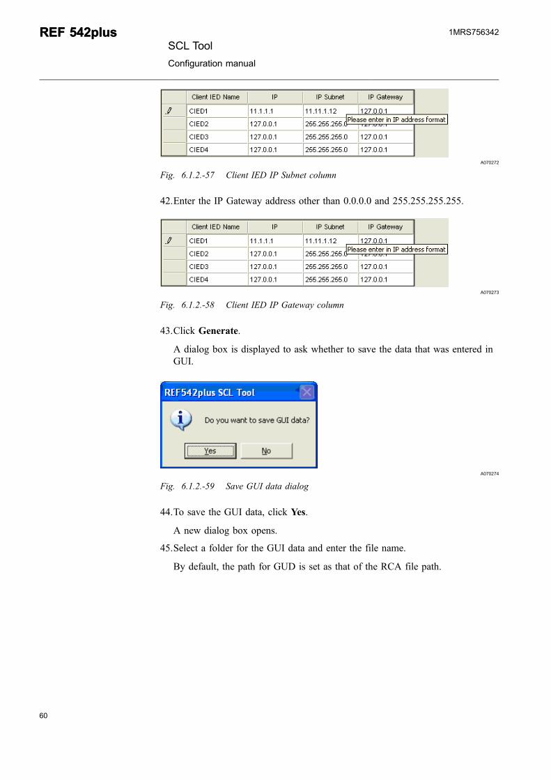
A070272
Fig. 6.1.2.-57 Client IED IP Subnet column
42.Enter the IP Gateway address other than 0.0.0.0 and 255.255.255.255.
A070273
Fig. 6.1.2.-58 Client IED IP Gateway column
43.Click Generate.
A dialog box is displayed to ask whether to save the data that was entered inGUI.
A070274
Fig. 6.1.2.-59 Save GUI data dialog
44.To save the GUI data, click Yes.
A new dialog box opens.
45.Select a folder for the GUI data and enter the file name.
By default, the path for GUD is set as that of the RCA file path.
60
REF 542plusREF 542plusSCL Tool
Configuration manual
1MRS756342
61
A070275
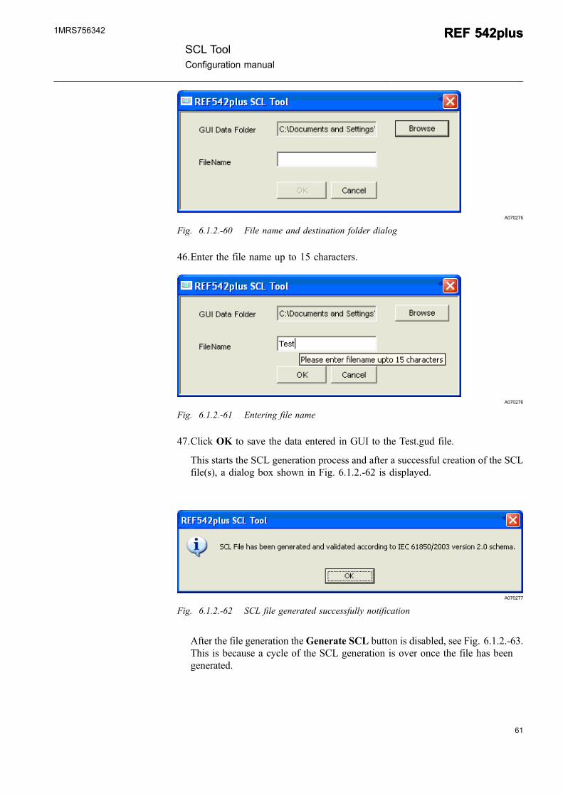
Fig. 6.1.2.-60 File name and destination folder dialog
46.Enter the file name up to 15 characters.
A070276
Fig. 6.1.2.-61 Entering file name
47.Click OK to save the data entered in GUI to the Test.gud file.
This starts the SCL generation process and after a successful creation of the SCLfile(s), a dialog box shown in Fig. 6.1.2.-62 is displayed.
A070277
Fig. 6.1.2.-62 SCL file generated successfully notification
After the file generation the Generate SCL button is disabled, see Fig. 6.1.2.-63.This is because a cycle of the SCL generation is over once the file has beengenerated.
SCL ToolConfiguration manual
REF 542plusREF 542plus1MRS756342
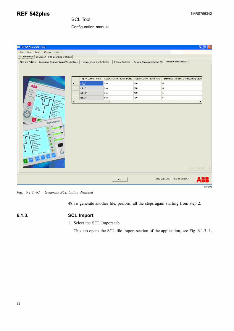
A070278
Fig. 6.1.2.-63 Generate SCL button disabled
48.To generate another file, perform all the steps again starting from step 2.
6.1.3. SCL Import
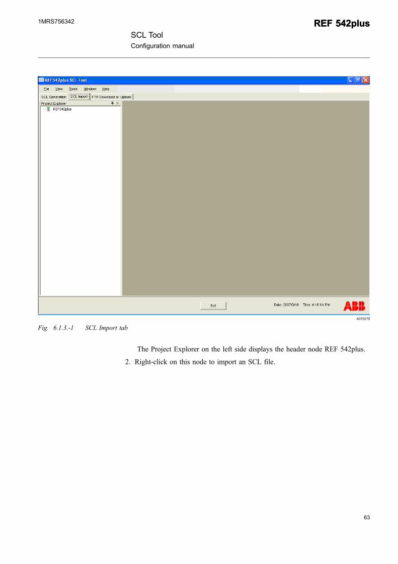
1. Select the SCL Import tab.
This tab opens the SCL file import section of the application, see Fig. 6.1.3.-1.
62
REF 542plusREF 542plusSCL Tool
Configuration manual
1MRS756342
63
A070279
Fig. 6.1.3.-1 SCL Import tab
The Project Explorer on the left side displays the header node REF 542plus.
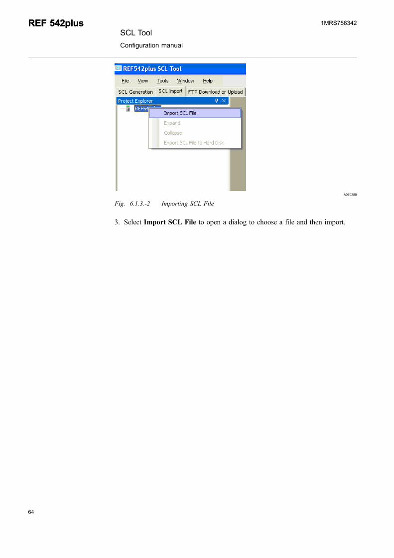
2. Right-click on this node to import an SCL file.
SCL ToolConfiguration manual
REF 542plusREF 542plus1MRS756342
A070280
Fig. 6.1.3.-2 Importing SCL File
3. Select Import SCL File to open a dialog to choose a file and then import.
64
REF 542plusREF 542plusSCL Tool
Configuration manual
1MRS756342
65
A070281
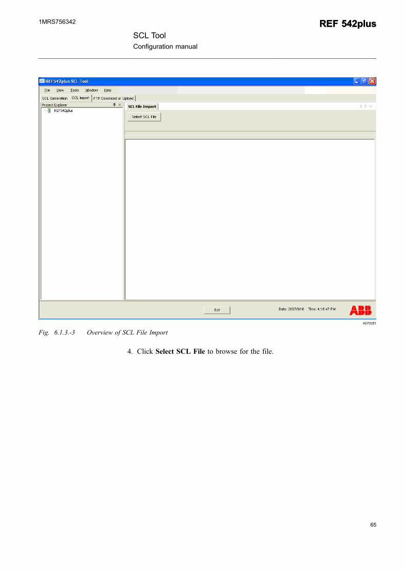
Fig. 6.1.3.-3 Overview of SCL File Import
4. Click Select SCL File to browse for the file.
SCL ToolConfiguration manual
REF 542plusREF 542plus1MRS756342
A070282
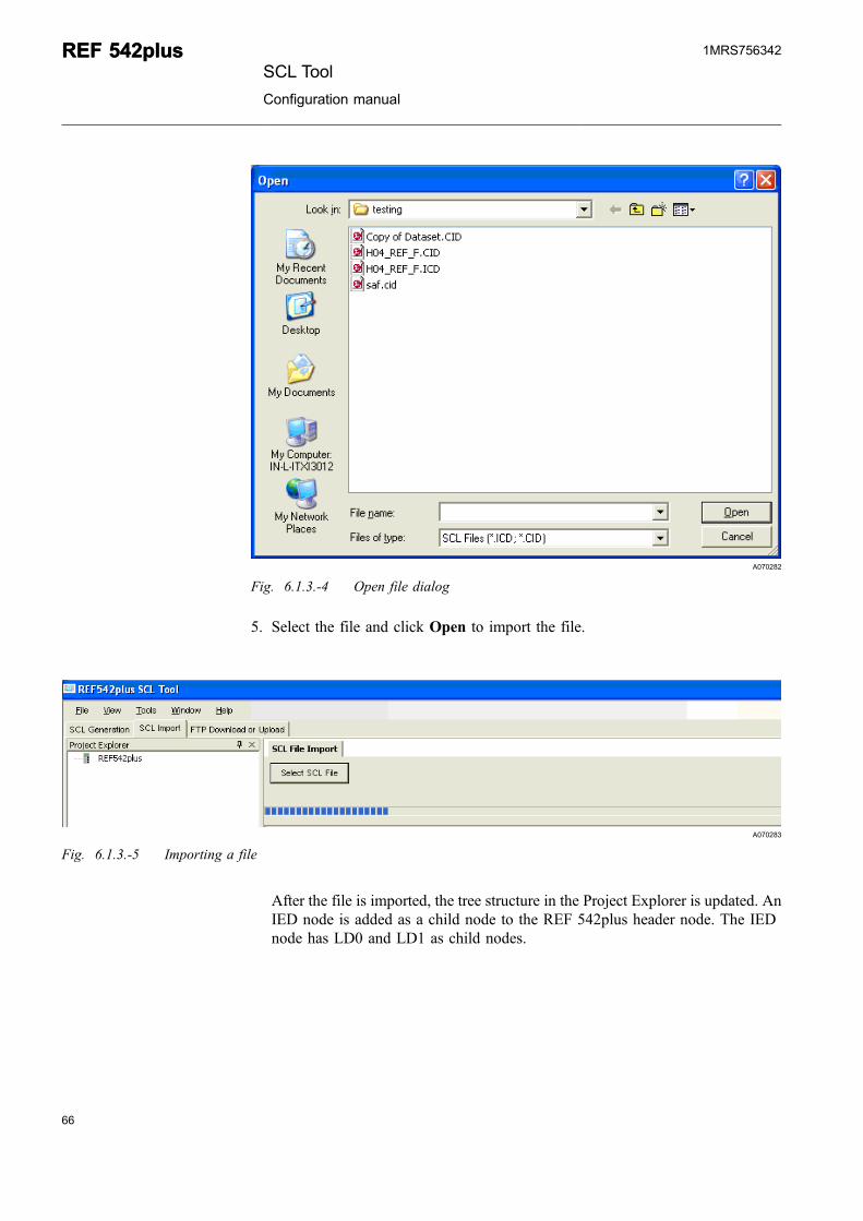
Fig. 6.1.3.-4 Open file dialog
5. Select the file and click Open to import the file.
A070283
Fig. 6.1.3.-5 Importing a file
After the file is imported, the tree structure in the Project Explorer is updated. AnIED node is added as a child node to the REF 542plus header node. The IEDnode has LD0 and LD1 as child nodes.
66
REF 542plusREF 542plusSCL Tool
Configuration manual
1MRS756342
67
A070284
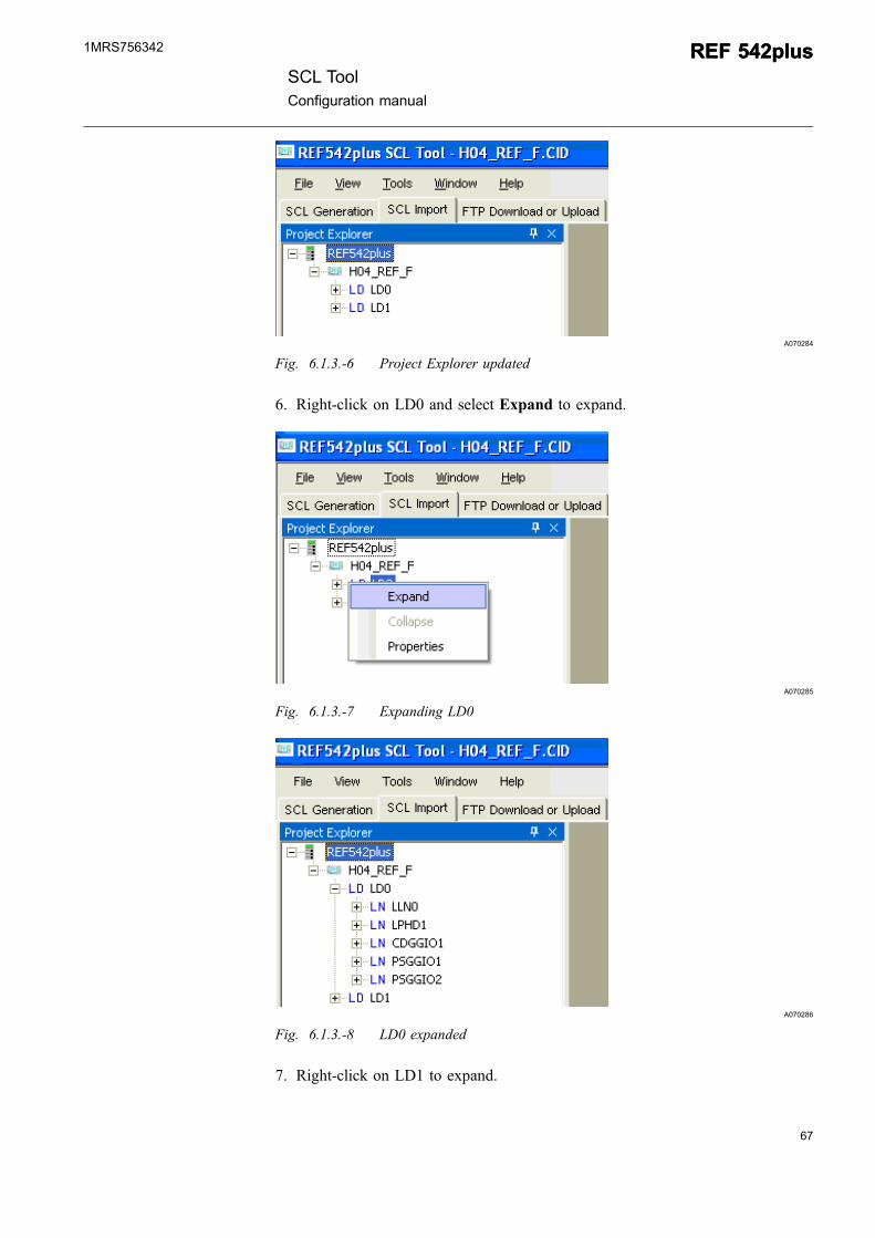
Fig. 6.1.3.-6 Project Explorer updated
6. Right-click on LD0 and select Expand to expand.
A070285
Fig. 6.1.3.-7 Expanding LD0
A070286
Fig. 6.1.3.-8 LD0 expanded
7. Right-click on LD1 to expand.
SCL ToolConfiguration manual
REF 542plusREF 542plus1MRS756342
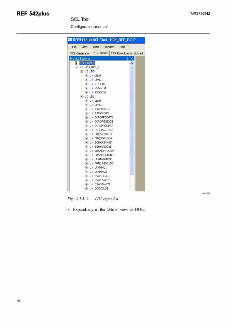
A070287
Fig. 6.1.3.-9 LD1 expanded
8. Expand any of the LNs to view its DOIs.
68
REF 542plusREF 542plusSCL Tool
Configuration manual
1MRS756342
69
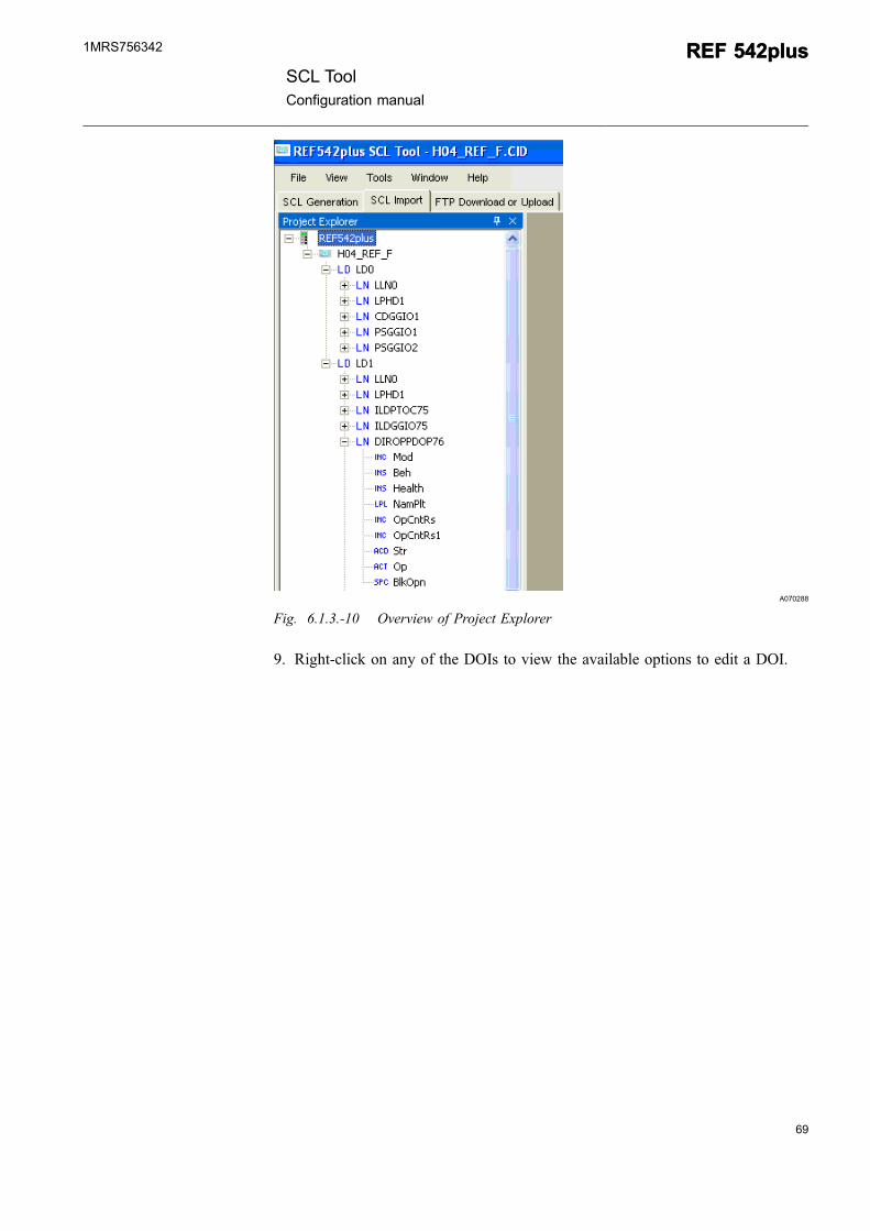
A070288
Fig. 6.1.3.-10 Overview of Project Explorer
9. Right-click on any of the DOIs to view the available options to edit a DOI.
SCL ToolConfiguration manual
REF 542plusREF 542plus1MRS756342
A070289
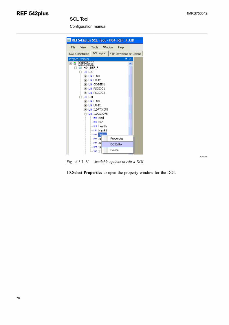
Fig. 6.1.3.-11 Available options to edit a DOI
10.Select Properties to open the property window for the DOI.
70
REF 542plusREF 542plusSCL Tool
Configuration manual
1MRS756342
71
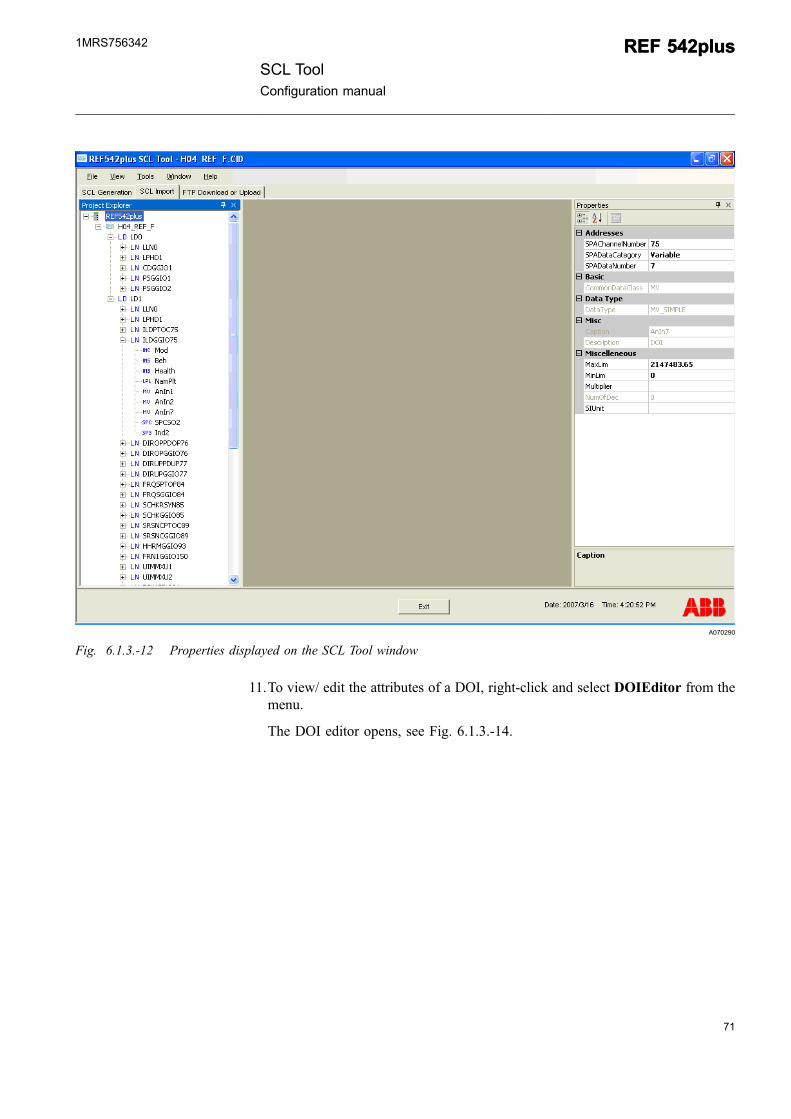
A070290
Fig. 6.1.3.-12 Properties displayed on the SCL Tool window
11.To view/ edit the attributes of a DOI, right-click and select DOIEditor from themenu.
The DOI editor opens, see Fig. 6.1.3.-14.
SCL ToolConfiguration manual
REF 542plusREF 542plus1MRS756342
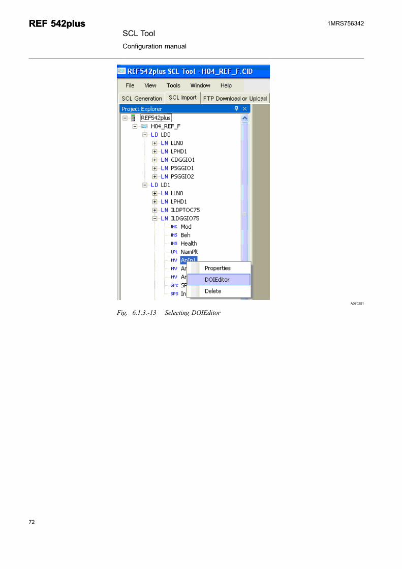
A070291
Fig. 6.1.3.-13 Selecting DOIEditor
72
REF 542plusREF 542plusSCL Tool
Configuration manual
1MRS756342
73
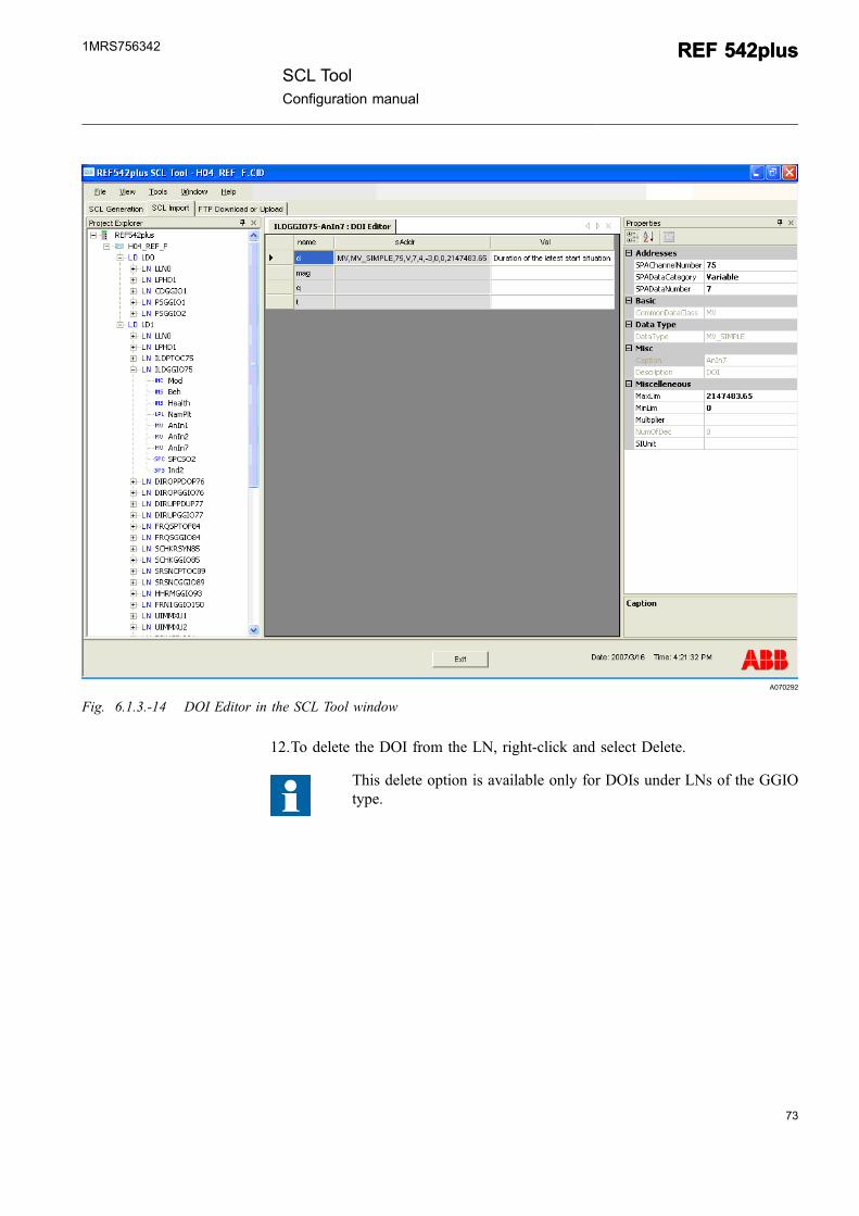
A070292
Fig. 6.1.3.-14 DOI Editor in the SCL Tool window
12.To delete the DOI from the LN, right-click and select Delete.
This delete option is available only for DOIs under LNs of the GGIOtype.
SCL ToolConfiguration manual
REF 542plusREF 542plus1MRS756342
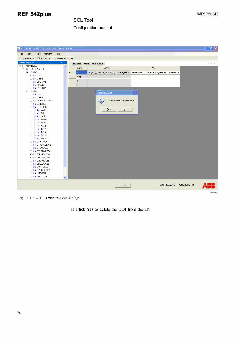
A070293
Fig. 6.1.3.-15 ObjectDelete dialog
13.Click Yes to delete the DOI from the LN.
74
REF 542plusREF 542plusSCL Tool
Configuration manual
1MRS756342
75
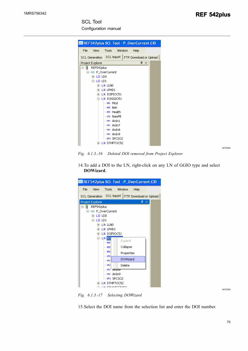
A070294
Fig. 6.1.3.-16 Deleted DOI removed from Project Explorer
14.To add a DOI to the LN, right-click on any LN of GGIO type and selectDOWizard.
A070295
Fig. 6.1.3.-17 Selecting DOWizard
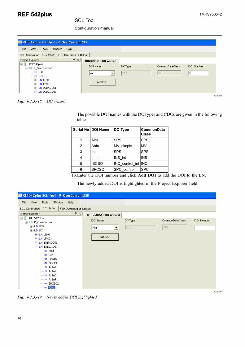
15.Select the DOI name from the selection list and enter the DOI number.
SCL ToolConfiguration manual
REF 542plusREF 542plus1MRS756342
A070296
Fig. 6.1.3.-18 DO Wizard
The possible DOI names with the DOTypes and CDCs are given in the followingtable.
Serial No DOI Name DO Type CommonData-Class
1 Alm SPS SPS
2 AnIn MV_simple MV
3 Ind SPS SPS
4 IntIn INS_int INS
5 ISCSO INC_control_int INC
6 SPCSO SPC_control SPC
16.Enter the DOI number and click Add DOI to add the DOI to the LN.
The newly added DOI is highlighted in the Project Explorer field.
A070297
Fig. 6.1.3.-19 Newly added DOI highlighted
76
REF 542plusREF 542plusSCL Tool
Configuration manual
1MRS756342
77
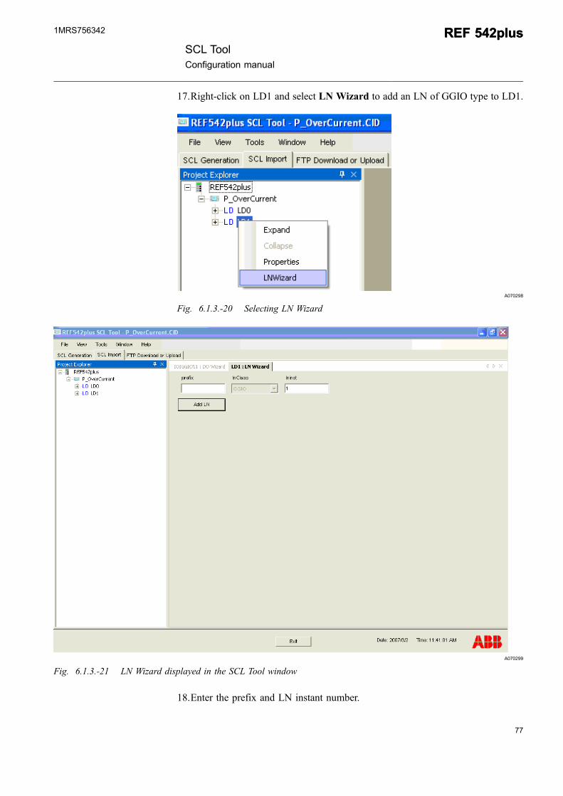
17.Right-click on LD1 and select LN Wizard to add an LN of GGIO type to LD1.
A070298
Fig. 6.1.3.-20 Selecting LN Wizard
A070299
Fig. 6.1.3.-21 LN Wizard displayed in the SCL Tool window
18.Enter the prefix and LN instant number.
SCL ToolConfiguration manual
REF 542plusREF 542plus1MRS756342
A070300
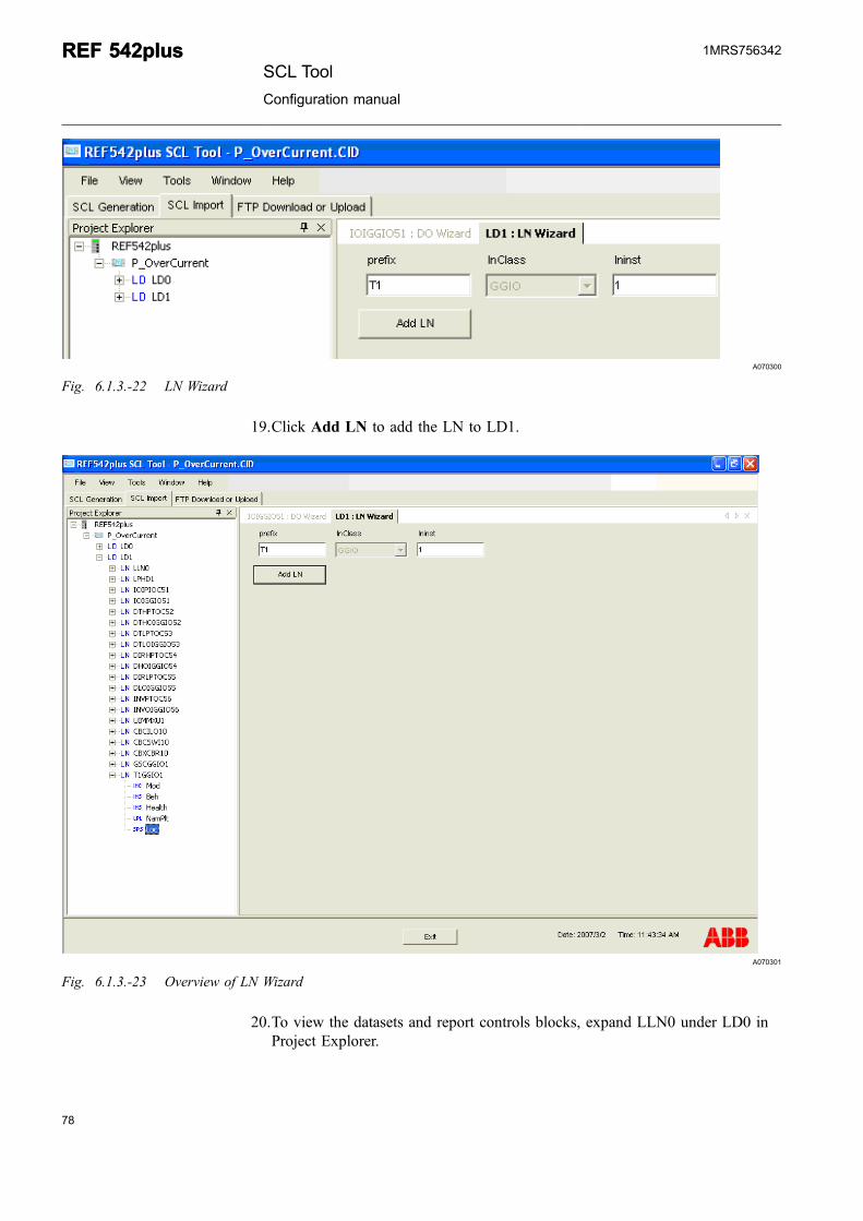
Fig. 6.1.3.-22 LN Wizard
19.Click Add LN to add the LN to LD1.
A070301
Fig. 6.1.3.-23 Overview of LN Wizard
20.To view the datasets and report controls blocks, expand LLN0 under LD0 inProject Explorer.
78
REF 542plusREF 542plusSCL Tool
Configuration manual
1MRS756342
79
A070302
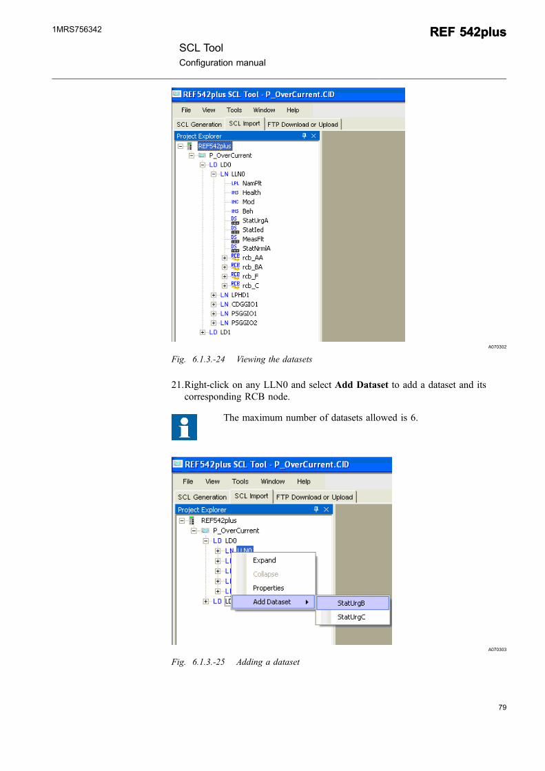
Fig. 6.1.3.-24 Viewing the datasets
21.Right-click on any LLN0 and select Add Dataset to add a dataset and itscorresponding RCB node.
The maximum number of datasets allowed is 6.
A070303
Fig. 6.1.3.-25 Adding a dataset
SCL ToolConfiguration manual
REF 542plusREF 542plus1MRS756342
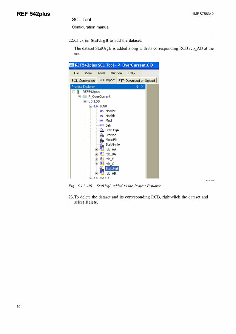
22.Click on StatUrgB to add the dataset.
The dataset StatUrgB is added along with its corresponding RCB rcb_AB at theend.
A070304
Fig. 6.1.3.-26 StatUrgB added to the Project Explorer
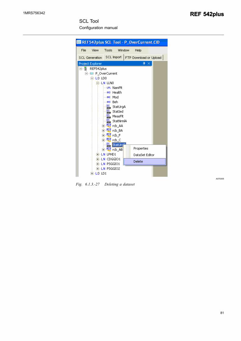
23.To delete the dataset and its corresponding RCB, right-click the dataset andselect Delete.
80
REF 542plusREF 542plusSCL Tool
Configuration manual
1MRS756342
81
A070305
Fig. 6.1.3.-27 Deleting a dataset
SCL ToolConfiguration manual
REF 542plusREF 542plus1MRS756342
A070306
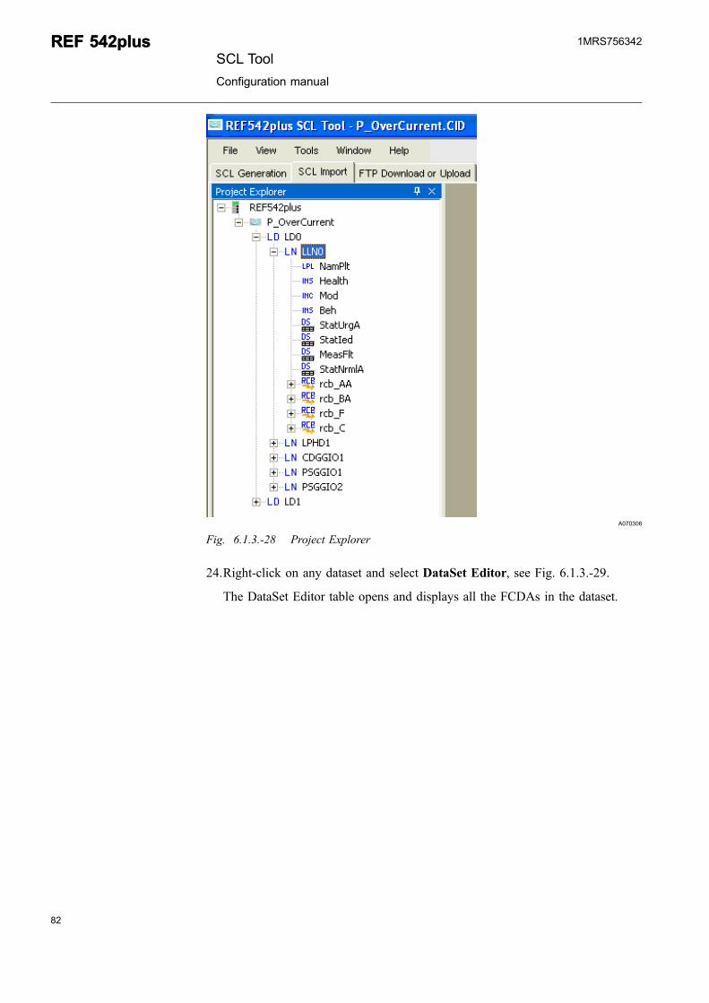
Fig. 6.1.3.-28 Project Explorer
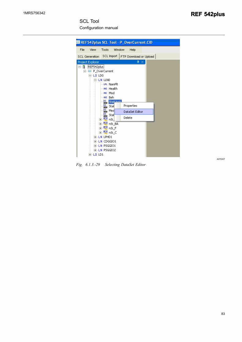
24.Right-click on any dataset and select DataSet Editor, see Fig. 6.1.3.-29.
The DataSet Editor table opens and displays all the FCDAs in the dataset.
82
REF 542plusREF 542plusSCL Tool
Configuration manual
1MRS756342
83
A070307
Fig. 6.1.3.-29 Selecting DataSet Editor
SCL ToolConfiguration manual
REF 542plusREF 542plus1MRS756342
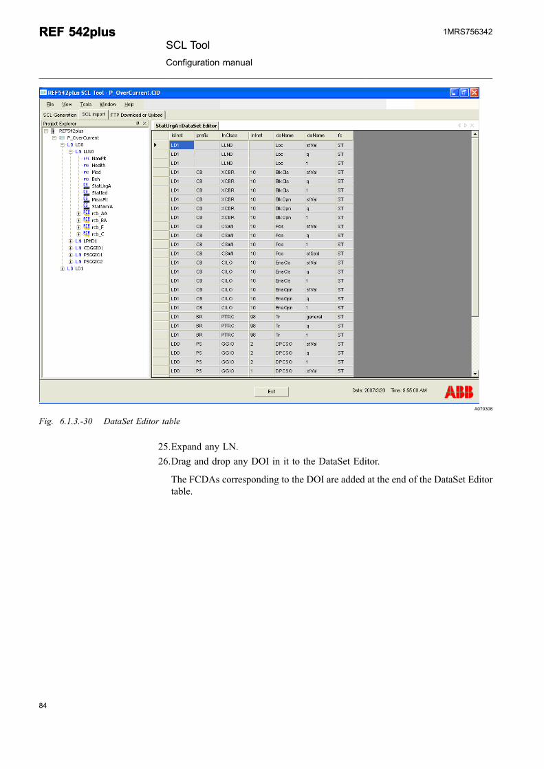
A070308
Fig. 6.1.3.-30 DataSet Editor table
25.Expand any LN.
26.Drag and drop any DOI in it to the DataSet Editor.
The FCDAs corresponding to the DOI are added at the end of the DataSet Editortable.
84
REF 542plusREF 542plusSCL Tool
Configuration manual
1MRS756342
85
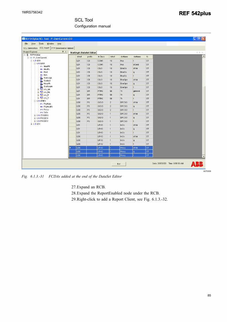
A070309
Fig. 6.1.3.-31 FCDAs added at the end of the DataSet Editor
27.Expand an RCB.
28.Expand the ReportEnabled node under the RCB.
29.Right-click to add a Report Client, see Fig. 6.1.3.-32.
SCL ToolConfiguration manual
REF 542plusREF 542plus1MRS756342
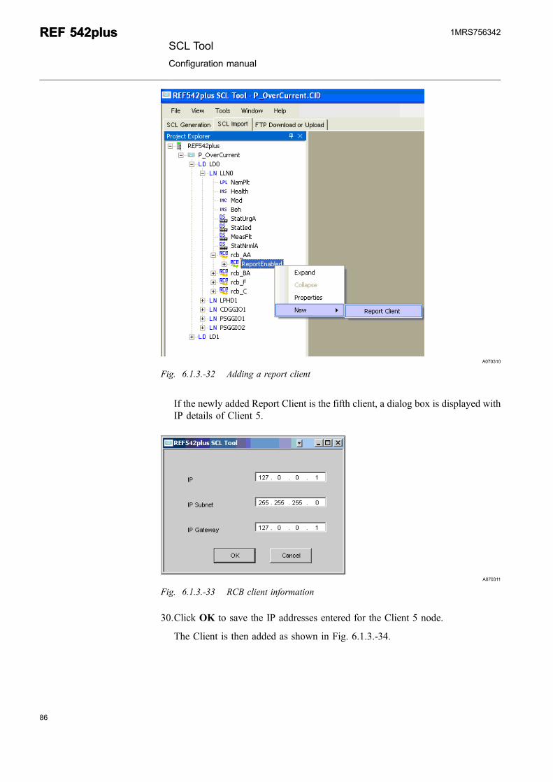
A070310
Fig. 6.1.3.-32 Adding a report client
If the newly added Report Client is the fifth client, a dialog box is displayed withIP details of Client 5.
A070311
Fig. 6.1.3.-33 RCB client information
30.Click OK to save the IP addresses entered for the Client 5 node.
The Client is then added as shown in Fig. 6.1.3.-34.
86
REF 542plusREF 542plusSCL Tool
Configuration manual
1MRS756342
87
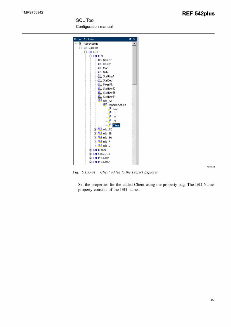
A070312
Fig. 6.1.3.-34 Client added to the Project Explorer
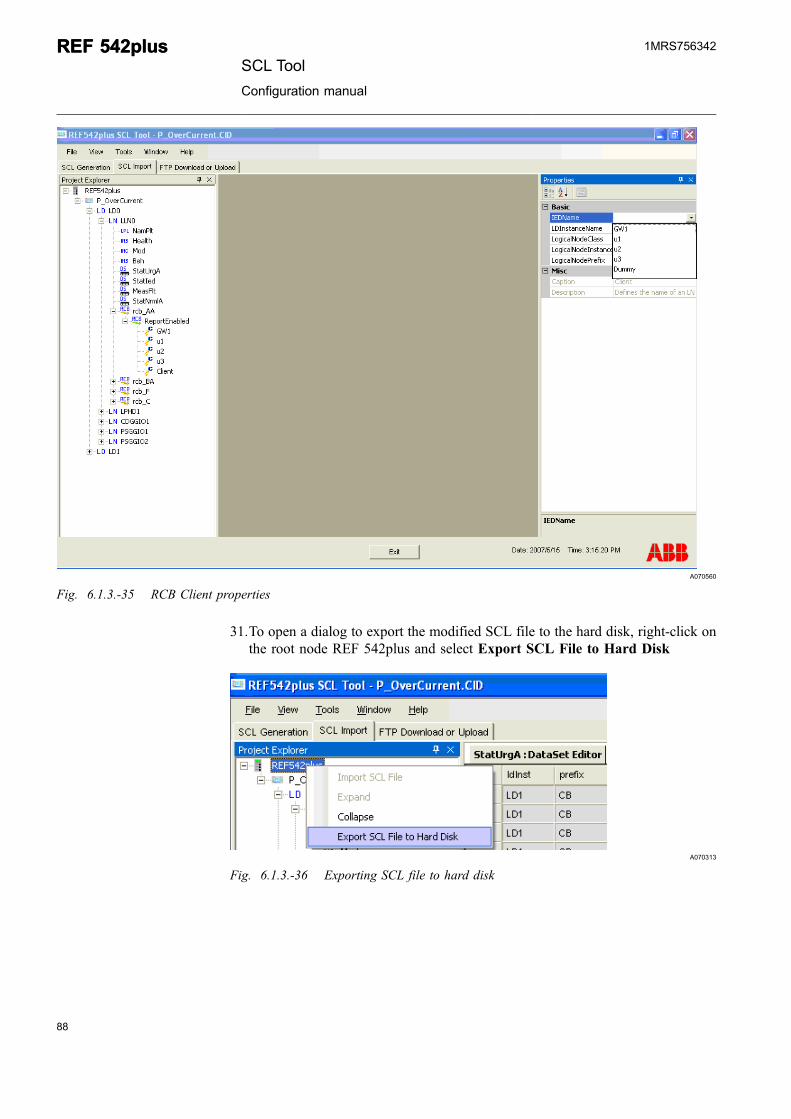
Set the properties for the added Client using the property bag. The IED Nameproperty consists of the IED names.
SCL ToolConfiguration manual
REF 542plusREF 542plus1MRS756342
A070560
Fig. 6.1.3.-35 RCB Client properties
31.To open a dialog to export the modified SCL file to the hard disk, right-click onthe root node REF 542plus and select Export SCL File to Hard Disk
A070313
Fig. 6.1.3.-36 Exporting SCL file to hard disk
88
REF 542plusREF 542plusSCL Tool
Configuration manual
1MRS756342
89
A070314
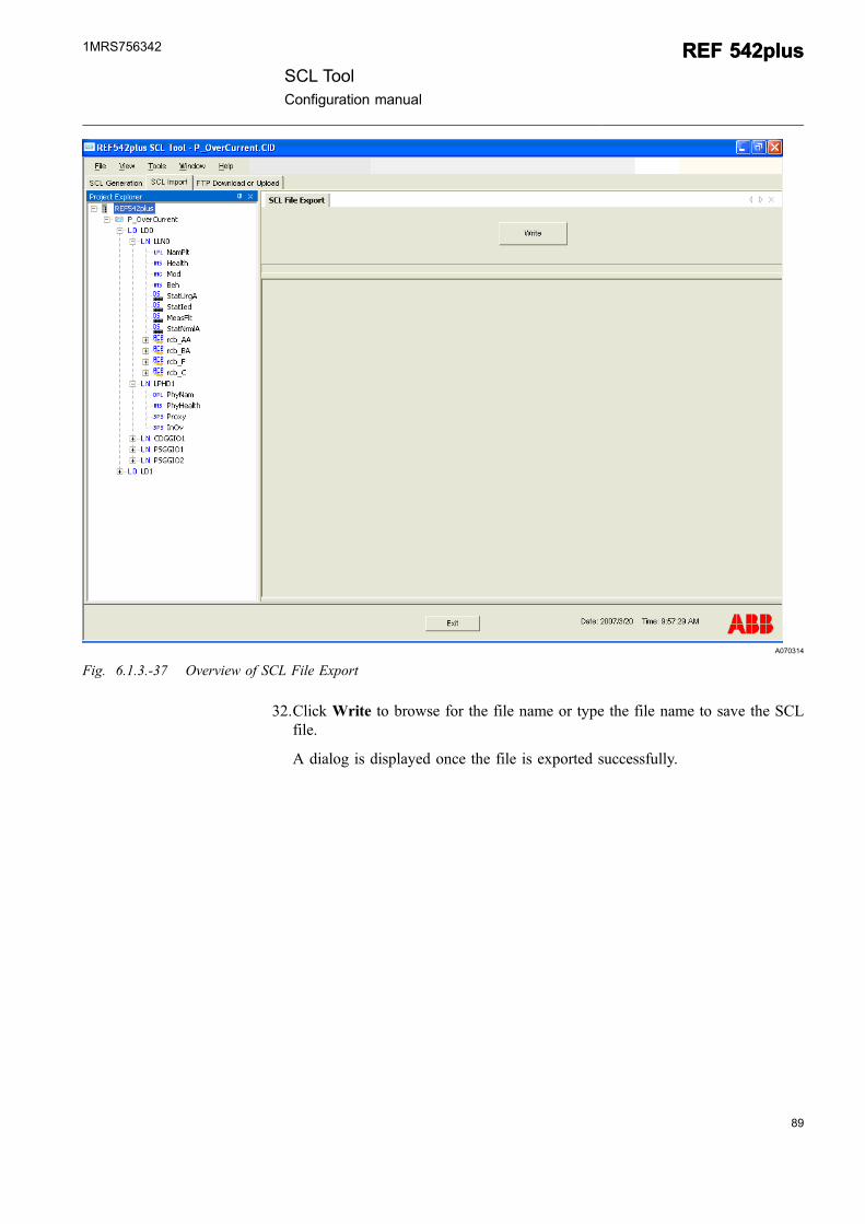
Fig. 6.1.3.-37 Overview of SCL File Export
32.Click Write to browse for the file name or type the file name to save the SCLfile.
A dialog is displayed once the file is exported successfully.
SCL ToolConfiguration manual
REF 542plusREF 542plus1MRS756342
A070315
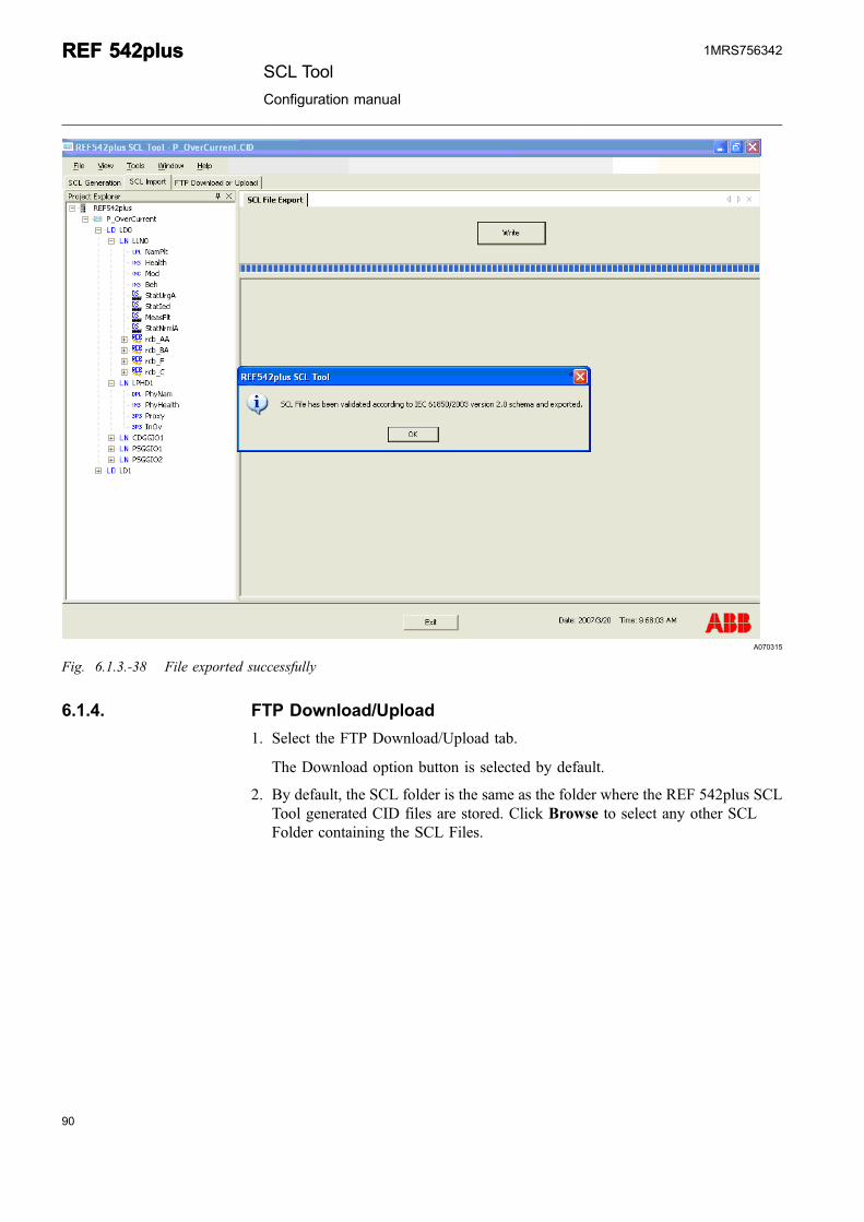
Fig. 6.1.3.-38 File exported successfully
6.1.4. FTP Download/Upload
1. Select the FTP Download/Upload tab.
The Download option button is selected by default.
2. By default, the SCL folder is the same as the folder where the REF 542plus SCLTool generated CID files are stored. Click Browse to select any other SCLFolder containing the SCL Files.
90
REF 542plusREF 542plusSCL Tool
Configuration manual
1MRS756342
91
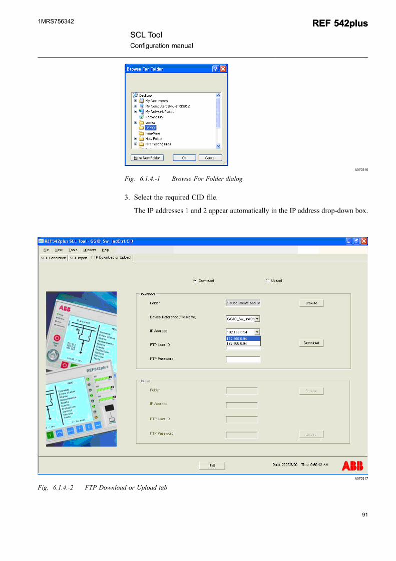
A070316
Fig. 6.1.4.-1 Browse For Folder dialog
3. Select the required CID file.
The IP addresses 1 and 2 appear automatically in the IP address drop-down box.
A070317
Fig. 6.1.4.-2 FTP Download or Upload tab
SCL ToolConfiguration manual
REF 542plusREF 542plus1MRS756342
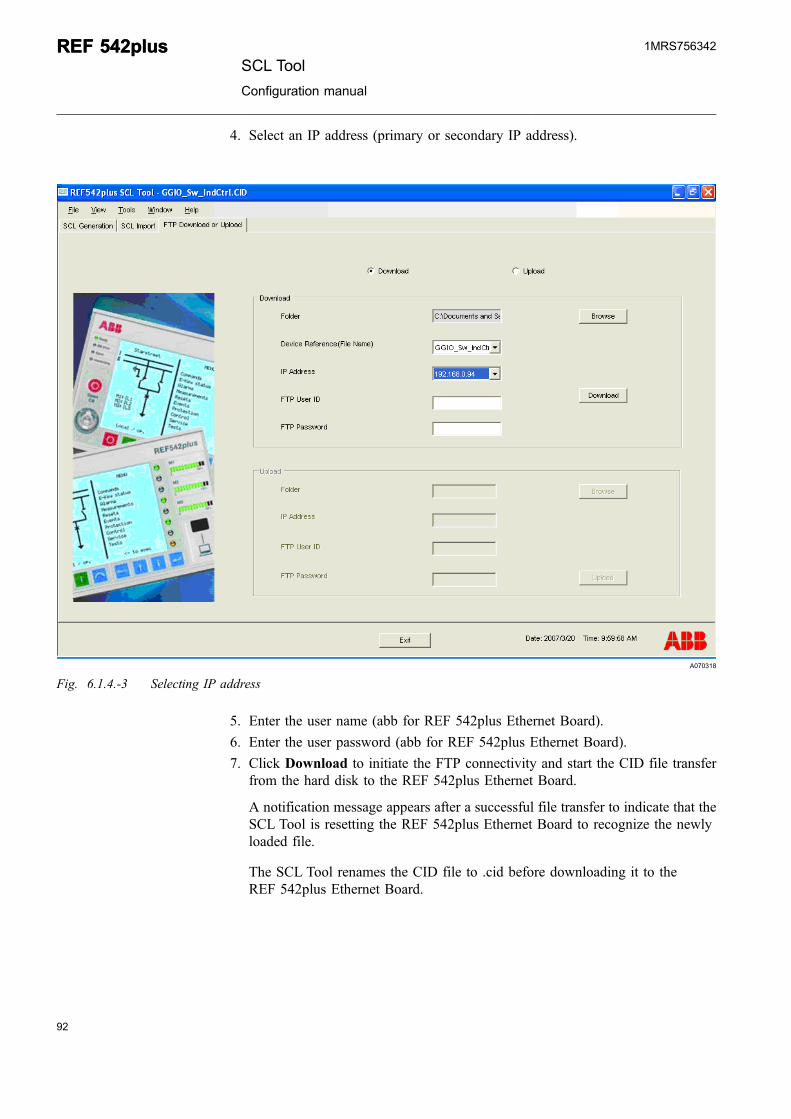
4. Select an IP address (primary or secondary IP address).
A070318
Fig. 6.1.4.-3 Selecting IP address
5. Enter the user name (abb for REF 542plus Ethernet Board).
6. Enter the user password (abb for REF 542plus Ethernet Board).
7. Click Download to initiate the FTP connectivity and start the CID file transferfrom the hard disk to the REF 542plus Ethernet Board.
A notification message appears after a successful file transfer to indicate that theSCL Tool is resetting the REF 542plus Ethernet Board to recognize the newlyloaded file.
The SCL Tool renames the CID file to .cid before downloading it to theREF 542plus Ethernet Board.
92
REF 542plusREF 542plusSCL Tool
Configuration manual
1MRS756342
93
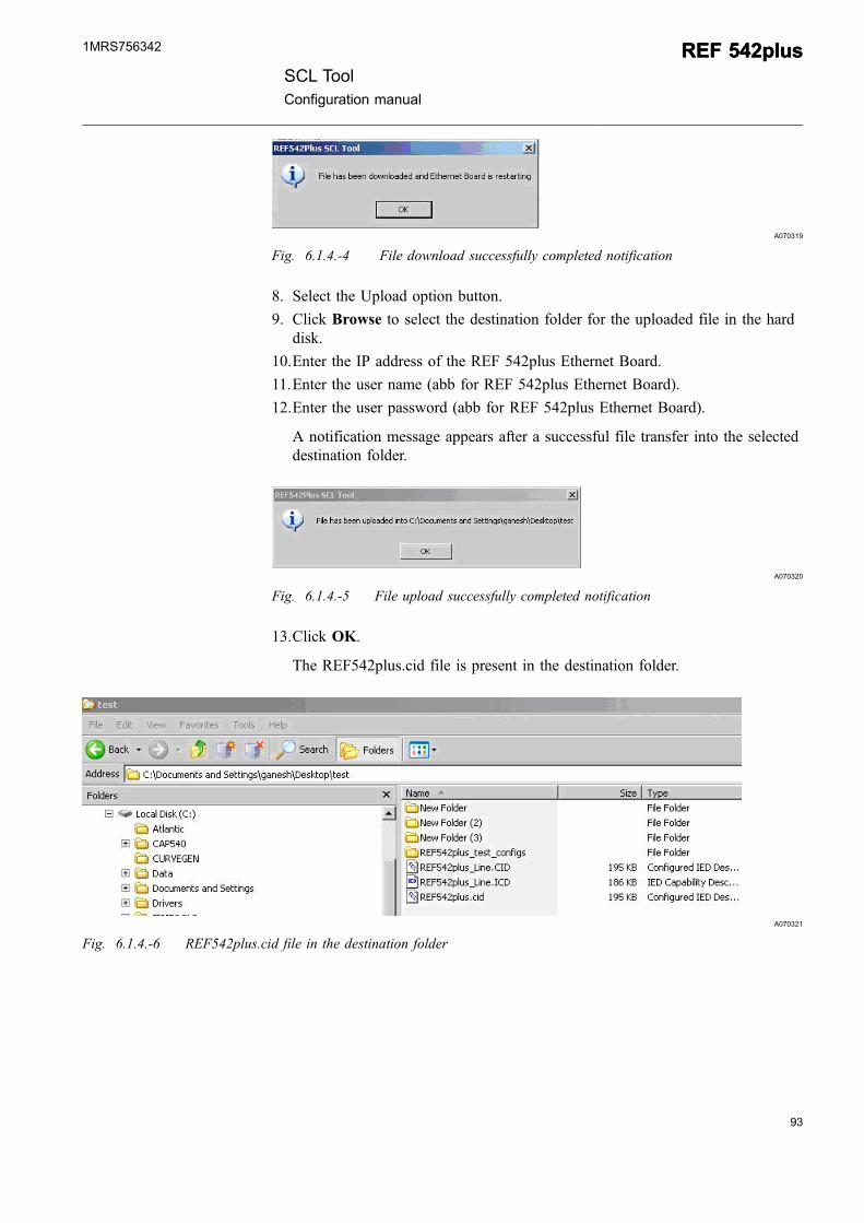
A070319
Fig. 6.1.4.-4 File download successfully completed notification
8. Select the Upload option button.
9. Click Browse to select the destination folder for the uploaded file in the harddisk.
10.Enter the IP address of the REF 542plus Ethernet Board.
11.Enter the user name (abb for REF 542plus Ethernet Board).
12.Enter the user password (abb for REF 542plus Ethernet Board).
A notification message appears after a successful file transfer into the selecteddestination folder.
A070320
Fig. 6.1.4.-5 File upload successfully completed notification
13.Click OK.
The REF542plus.cid file is present in the destination folder.
A070321
Fig. 6.1.4.-6 REF542plus.cid file in the destination folder
SCL ToolConfiguration manual
REF 542plusREF 542plus1MRS756342
6.2.SCL core component
The SCL Tool core component interacts with the two XML file pools which aregenerated to construct the REF 542plus SCL file(s) as per user configuration. Thefile pools are the User data XML file pool with the REF542plusconfiguration.xmlfile, and the 61850 XML file pool.
A brief explanation is given for the user to understand where exactly the userinformation is used in the SCL files. The user entries in the SCL Tool GUI arecompared with the final form of the SCL files.
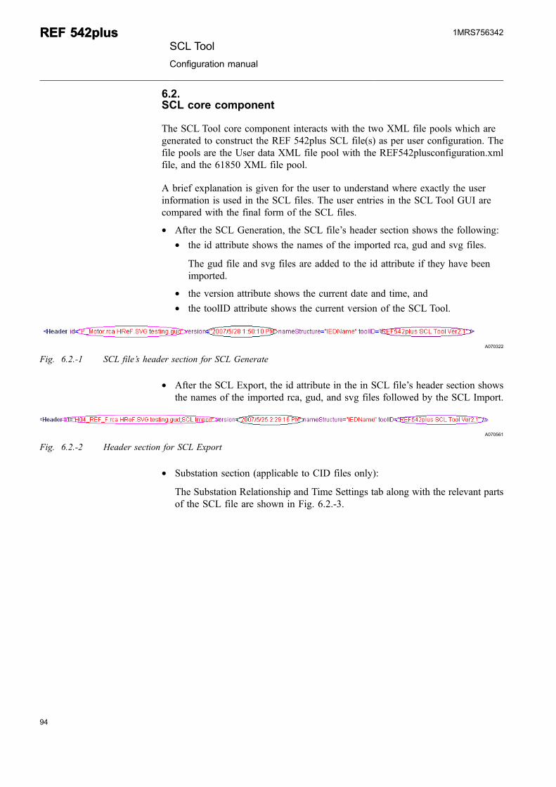
* After the SCL Generation, the SCL file’s header section shows the following:* the id attribute shows the names of the imported rca, gud and svg files.
The gud file and svg files are added to the id attribute if they have beenimported.
* the version attribute shows the current date and time, and* the toolID attribute shows the current version of the SCL Tool.
A070322
Fig. 6.2.-1 SCL file’s header section for SCL Generate
* After the SCL Export, the id attribute in the in SCL file’s header section showsthe names of the imported rca, gud, and svg files followed by the SCL Import.
A070561
Fig. 6.2.-2 Header section for SCL Export
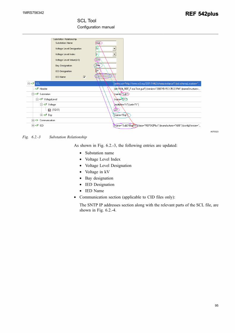
* Substation section (applicable to CID files only):
The Substation Relationship and Time Settings tab along with the relevant partsof the SCL file are shown in Fig. 6.2.-3.
94
REF 542plusREF 542plusSCL Tool
Configuration manual
1MRS756342
95
A070323
Fig. 6.2.-3 Substation Relationship
As shown in Fig. 6.2.-3, the following entries are updated:
* Substation name* Voltage Level Index* Voltage Level Designation* Voltage in kV* Bay designation* IED Designation* IED Name
* Communication section (applicable to CID files only):
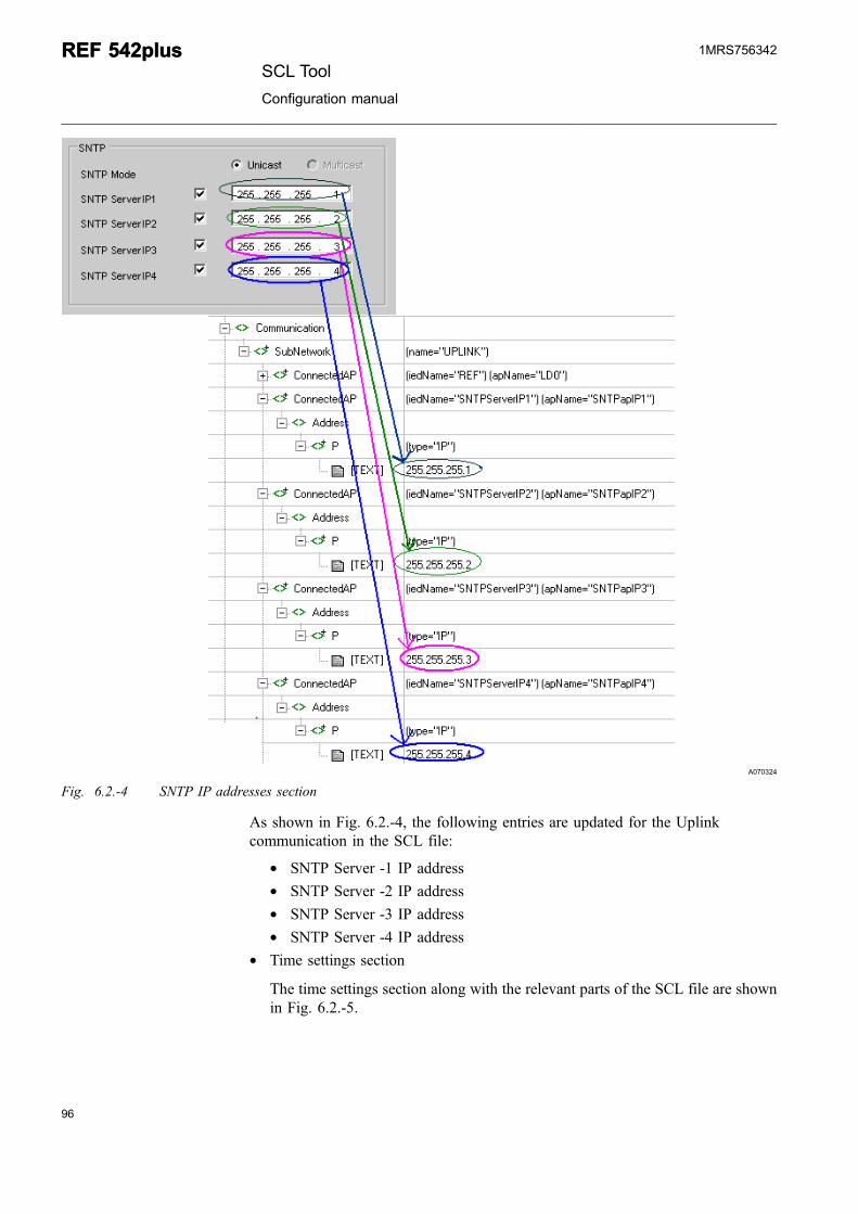
The SNTP IP addresses section along with the relevant parts of the SCL file, areshown in Fig. 6.2.-4.
SCL ToolConfiguration manual
REF 542plusREF 542plus1MRS756342
A070324
Fig. 6.2.-4 SNTP IP addresses section
As shown in Fig. 6.2.-4, the following entries are updated for the Uplinkcommunication in the SCL file:
* SNTP Server -1 IP address* SNTP Server -2 IP address* SNTP Server -3 IP address* SNTP Server -4 IP address
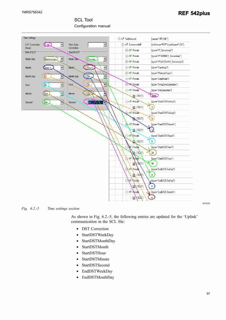
* Time settings section
The time settings section along with the relevant parts of the SCL file are shownin Fig. 6.2.-5.
96
REF 542plusREF 542plusSCL Tool
Configuration manual
1MRS756342
97
A070325
Fig. 6.2.-5 Time settings section
As shown in Fig. 6.2.-5, the following entries are updated for the ‘Uplink’communication in the SCL file:
* DST Correction* StartDSTWeekDay* StartDSTMonthDay* StartDSTMonth* StartDSTHour* StartDSTMinute* StartDSTSecond* EndDSTWeekDay* EndDSTMonthDay
SCL ToolConfiguration manual
REF 542plusREF 542plus1MRS756342
* EndDSTMonth* EndDSTHour* EndDSTMinute* EndDSTSecond
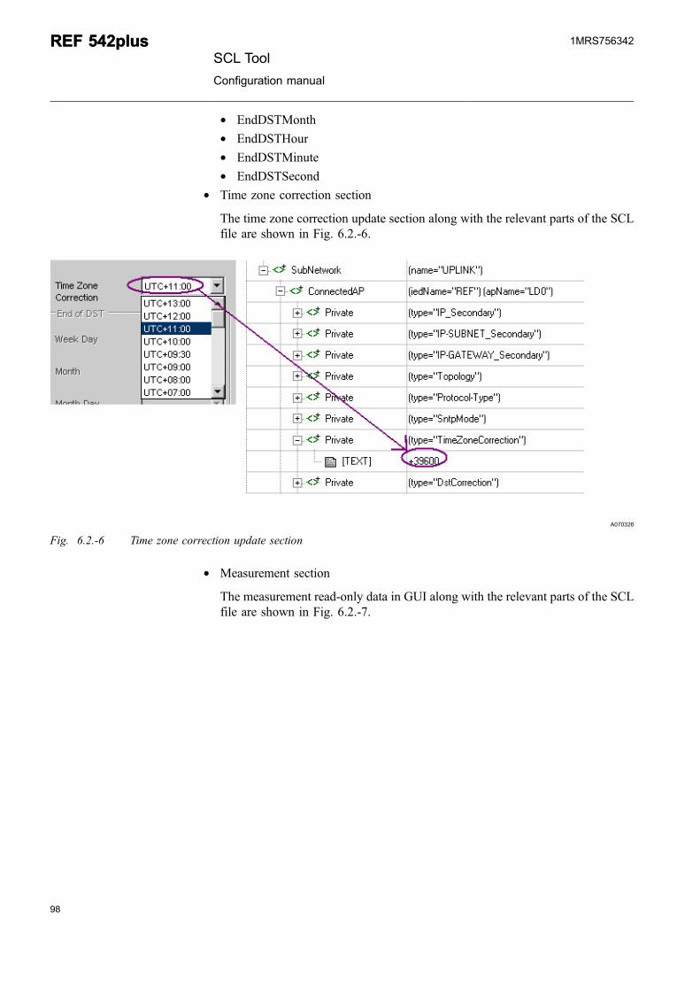
* Time zone correction section
The time zone correction update section along with the relevant parts of the SCLfile are shown in Fig. 6.2.-6.
A070326
Fig. 6.2.-6 Time zone correction update section
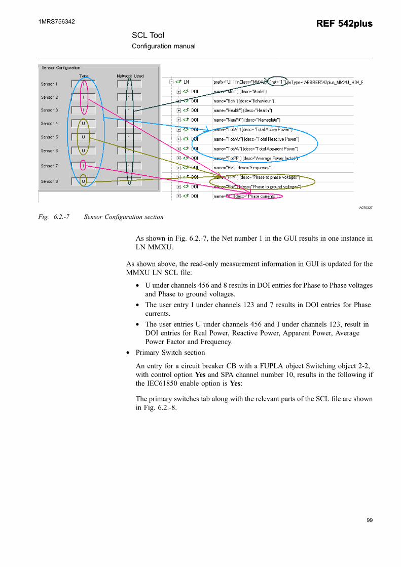
* Measurement section
The measurement read-only data in GUI along with the relevant parts of the SCLfile are shown in Fig. 6.2.-7.
98
REF 542plusREF 542plusSCL Tool
Configuration manual
1MRS756342
99
A070327
Fig. 6.2.-7 Sensor Configuration section
As shown in Fig. 6.2.-7, the Net number 1 in the GUI results in one instance inLN MMXU.
As shown above, the read-only measurement information in GUI is updated for theMMXU LN SCL file:
* U under channels 456 and 8 results in DOI entries for Phase to Phase voltagesand Phase to ground voltages.
* The user entry I under channels 123 and 7 results in DOI entries for Phasecurrents.
* The user entries U under channels 456 and I under channels 123, result inDOI entries for Real Power, Reactive Power, Apparent Power, AveragePower Factor and Frequency.
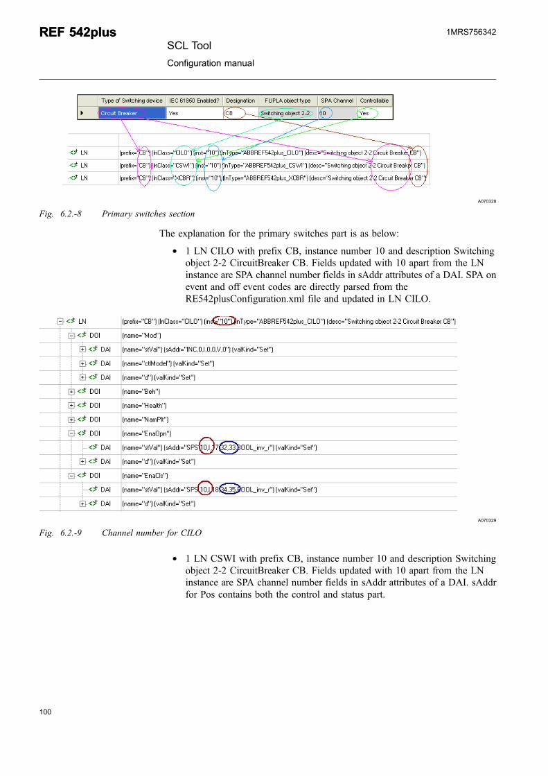
* Primary Switch section
An entry for a circuit breaker CB with a FUPLA object Switching object 2-2,with control option Yes and SPA channel number 10, results in the following ifthe IEC61850 enable option is Yes:
The primary switches tab along with the relevant parts of the SCL file are shownin Fig. 6.2.-8.
SCL ToolConfiguration manual
REF 542plusREF 542plus1MRS756342
A070328
Fig. 6.2.-8 Primary switches section
The explanation for the primary switches part is as below:
* 1 LN CILO with prefix CB, instance number 10 and description Switchingobject 2-2 CircuitBreaker CB. Fields updated with 10 apart from the LNinstance are SPA channel number fields in sAddr attributes of a DAI. SPA onevent and off event codes are directly parsed from theRE542plusConfiguration.xml file and updated in LN CILO.
A070329
Fig. 6.2.-9 Channel number for CILO
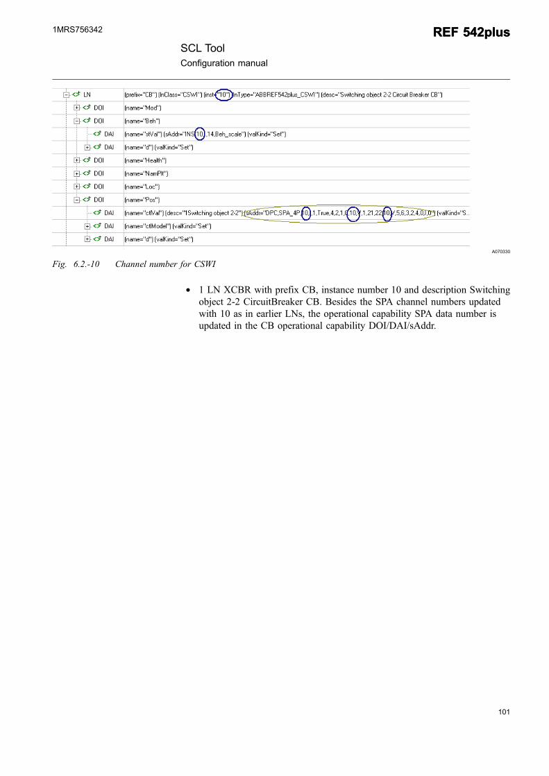
* 1 LN CSWI with prefix CB, instance number 10 and description Switchingobject 2-2 CircuitBreaker CB. Fields updated with 10 apart from the LNinstance are SPA channel number fields in sAddr attributes of a DAI. sAddrfor Pos contains both the control and status part.
100
REF 542plusREF 542plusSCL Tool
Configuration manual
1MRS756342
101
A070330
Fig. 6.2.-10 Channel number for CSWI
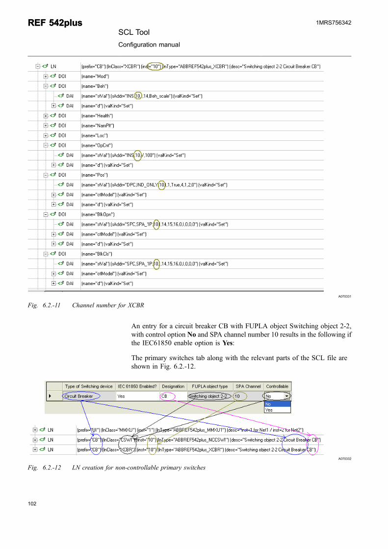
* 1 LN XCBR with prefix CB, instance number 10 and description Switchingobject 2-2 CircuitBreaker CB. Besides the SPA channel numbers updatedwith 10 as in earlier LNs, the operational capability SPA data number isupdated in the CB operational capability DOI/DAI/sAddr.
SCL ToolConfiguration manual
REF 542plusREF 542plus1MRS756342
A070331
Fig. 6.2.-11 Channel number for XCBR
An entry for a circuit breaker CB with FUPLA object Switching object 2-2,with control option No and SPA channel number 10 results in the following ifthe IEC61850 enable option is Yes:
The primary switches tab along with the relevant parts of the SCL file areshown in Fig. 6.2.-12.
A070332
Fig. 6.2.-12 LN creation for non-controllable primary switches
102
REF 542plusREF 542plusSCL Tool
Configuration manual
1MRS756342
103
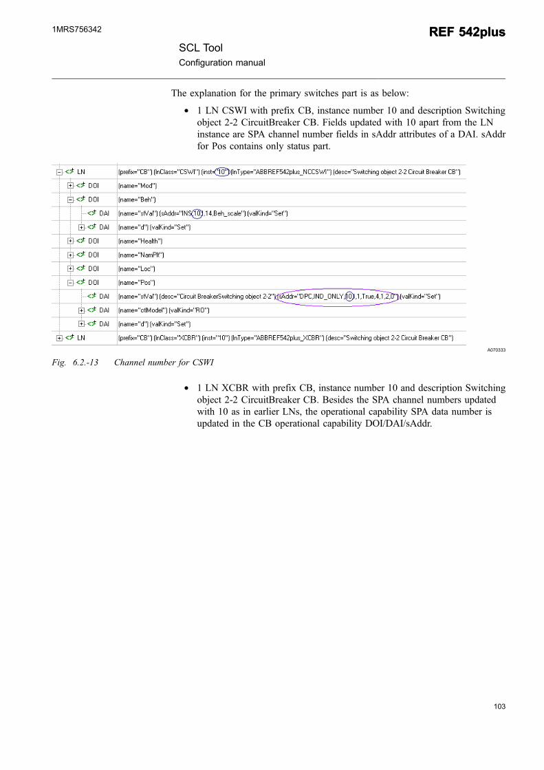
The explanation for the primary switches part is as below:
* 1 LN CSWI with prefix CB, instance number 10 and description Switchingobject 2-2 CircuitBreaker CB. Fields updated with 10 apart from the LNinstance are SPA channel number fields in sAddr attributes of a DAI. sAddrfor Pos contains only status part.
A070333
Fig. 6.2.-13 Channel number for CSWI
* 1 LN XCBR with prefix CB, instance number 10 and description Switchingobject 2-2 CircuitBreaker CB. Besides the SPA channel numbers updatedwith 10 as in earlier LNs, the operational capability SPA data number isupdated in the CB operational capability DOI/DAI/sAddr.
SCL ToolConfiguration manual
REF 542plusREF 542plus1MRS756342
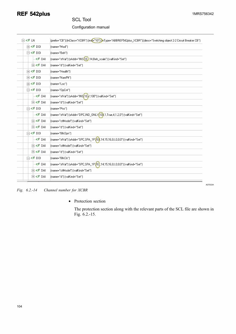
A070334
Fig. 6.2.-14 Channel number for XCBR
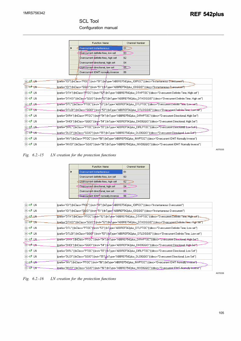
* Protection section
The protection section along with the relevant parts of the SCL file are shown inFig. 6.2.-15.
104
REF 542plusREF 542plusSCL Tool
Configuration manual
1MRS756342
105
A070335
Fig. 6.2.-15 LN creation for the protection functions
A070336
Fig. 6.2.-16 LN creation for the protection functions
SCL ToolConfiguration manual
REF 542plusREF 542plus1MRS756342
As shown above, the following data is updated:
* Depending on the SPA channel parsed from the REF542plusConfiguration.xml file, the corresponding protection LNs are included. For example,Overcurrent directional, low set function has the SPA channel number 55 andhence two LNs of the PIOC class and GGIO class with the instance numbers55 are included.
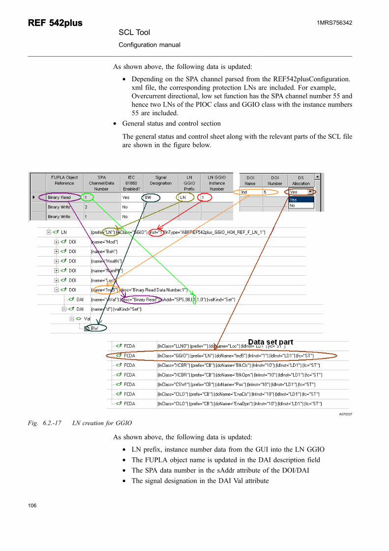
* General status and control section
The general status and control sheet along with the relevant parts of the SCL fileare shown in the figure below.
A070337
Fig. 6.2.-17 LN creation for GGIO
As shown above, the following data is updated:
* LN prefix, instance number data from the GUI into the LN GGIO* The FUPLA object name is updated in the DAI description field* The SPA data number in the sAddr attribute of the DOI/DAI* The signal designation in the DAI Val attribute
106
REF 542plusREF 542plusSCL Tool
Configuration manual
1MRS756342
107
* The combined DOI name and number as the DOI name attribute* The Data set enabled results in the addition of the DOI in the dataset
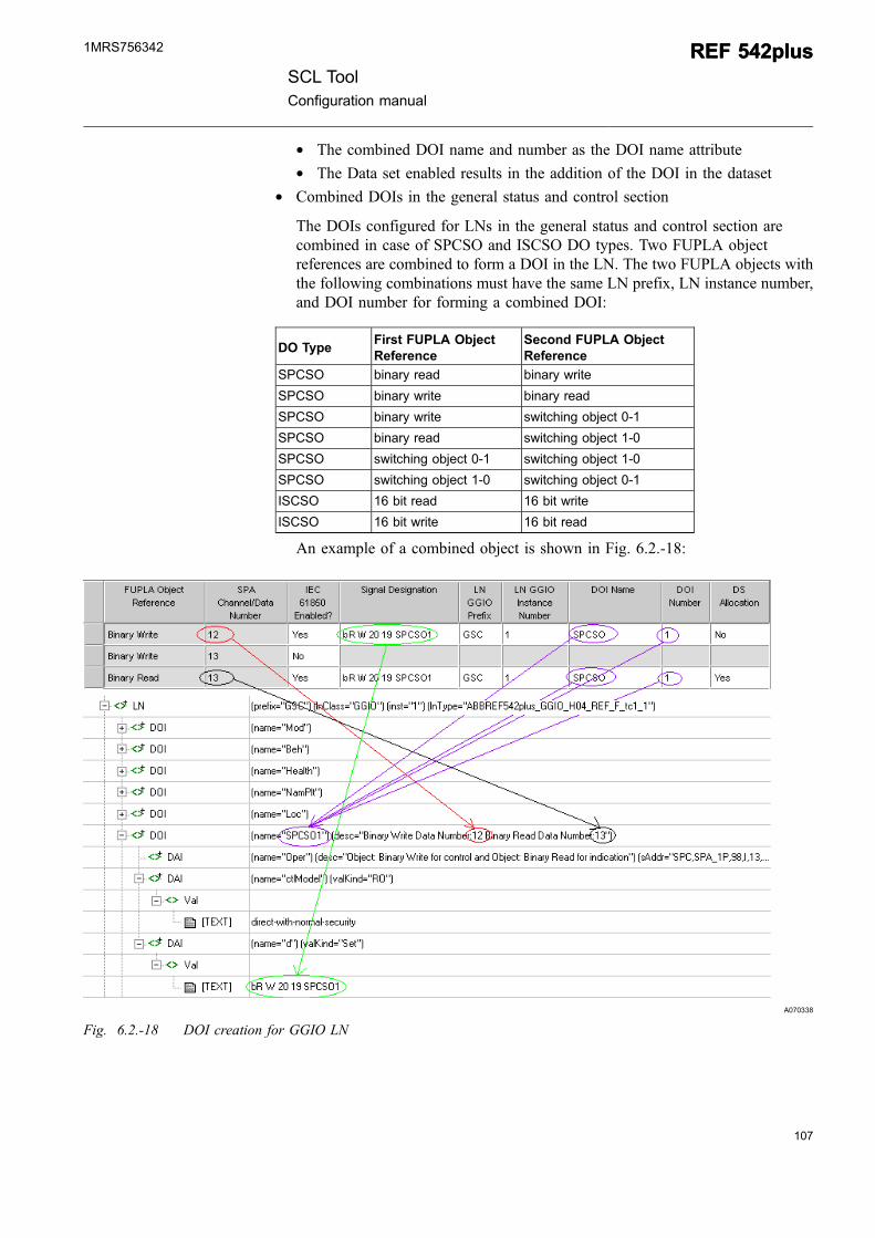
* Combined DOIs in the general status and control section
The DOIs configured for LNs in the general status and control section arecombined in case of SPCSO and ISCSO DO types. Two FUPLA objectreferences are combined to form a DOI in the LN. The two FUPLA objects withthe following combinations must have the same LN prefix, LN instance number,and DOI number for forming a combined DOI:
DO TypeFirst FUPLA ObjectReference
Second FUPLA ObjectReference
SPCSO binary read binary write
SPCSO binary write binary read
SPCSO binary write switching object 0-1
SPCSO binary read switching object 1-0
SPCSO switching object 0-1 switching object 1-0
SPCSO switching object 1-0 switching object 0-1
ISCSO 16 bit read 16 bit write
ISCSO 16 bit write 16 bit read
An example of a combined object is shown in Fig. 6.2.-18:
A070338
Fig. 6.2.-18 DOI creation for GGIO LN
SCL ToolConfiguration manual
REF 542plusREF 542plus1MRS756342
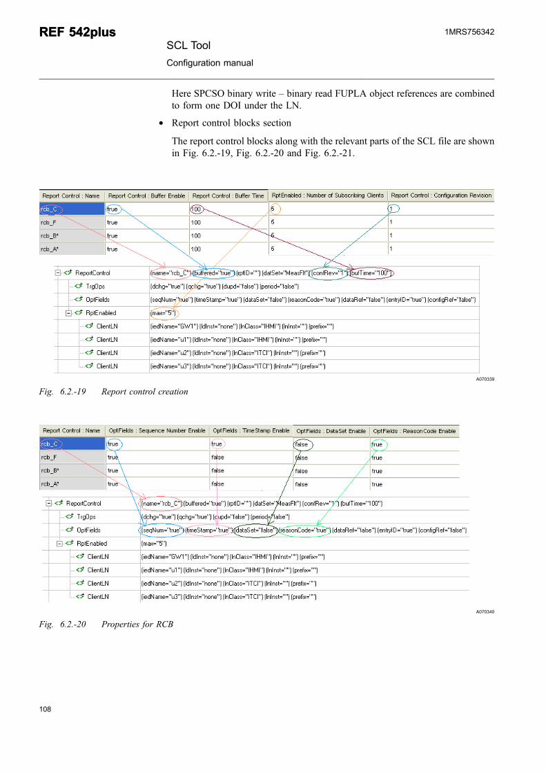
Here SPCSO binary write – binary read FUPLA object references are combinedto form one DOI under the LN.
* Report control blocks section
The report control blocks along with the relevant parts of the SCL file are shownin Fig. 6.2.-19, Fig. 6.2.-20 and Fig. 6.2.-21.
A070339
Fig. 6.2.-19 Report control creation
A070340
Fig. 6.2.-20 Properties for RCB
108
REF 542plusREF 542plusSCL Tool
Configuration manual
1MRS756342
109
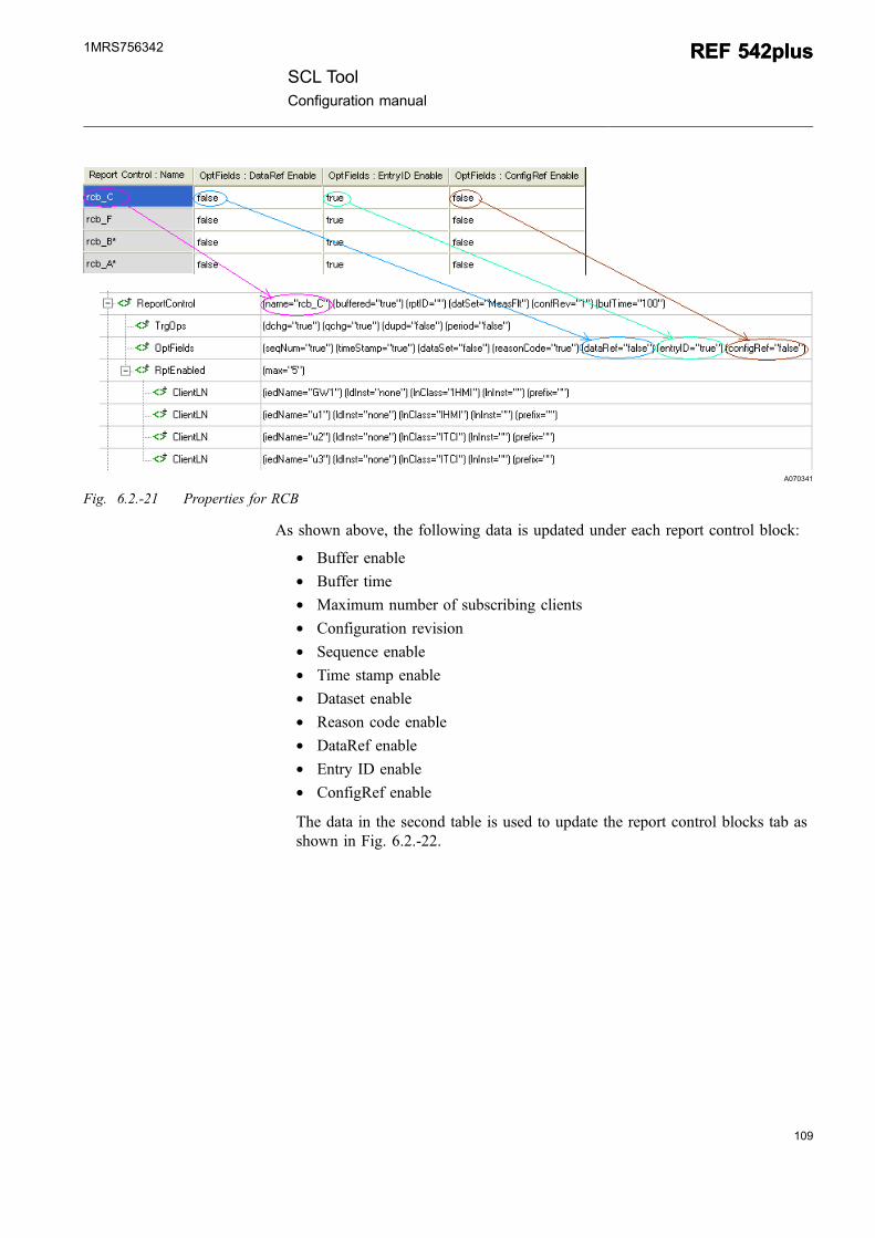
A070341
Fig. 6.2.-21 Properties for RCB
As shown above, the following data is updated under each report control block:
* Buffer enable* Buffer time* Maximum number of subscribing clients* Configuration revision* Sequence enable* Time stamp enable* Dataset enable* Reason code enable* DataRef enable* Entry ID enable* ConfigRef enable
The data in the second table is used to update the report control blocks tab asshown in Fig. 6.2.-22.
SCL ToolConfiguration manual
REF 542plusREF 542plus1MRS756342
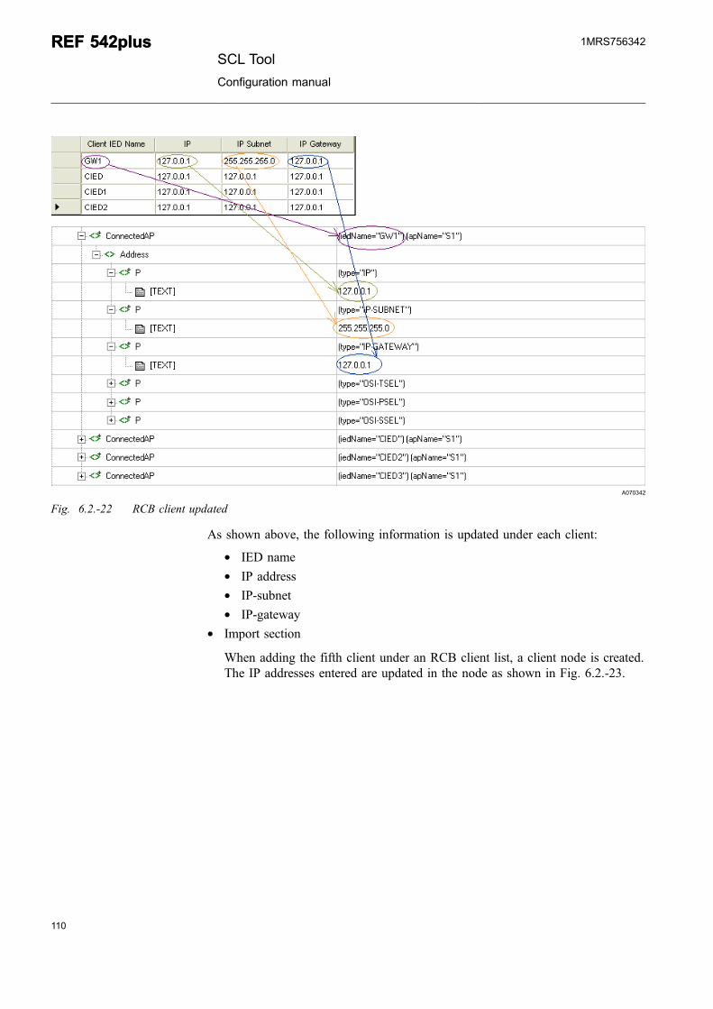
A070342
Fig. 6.2.-22 RCB client updated
As shown above, the following information is updated under each client:
* IED name* IP address* IP-subnet* IP-gateway
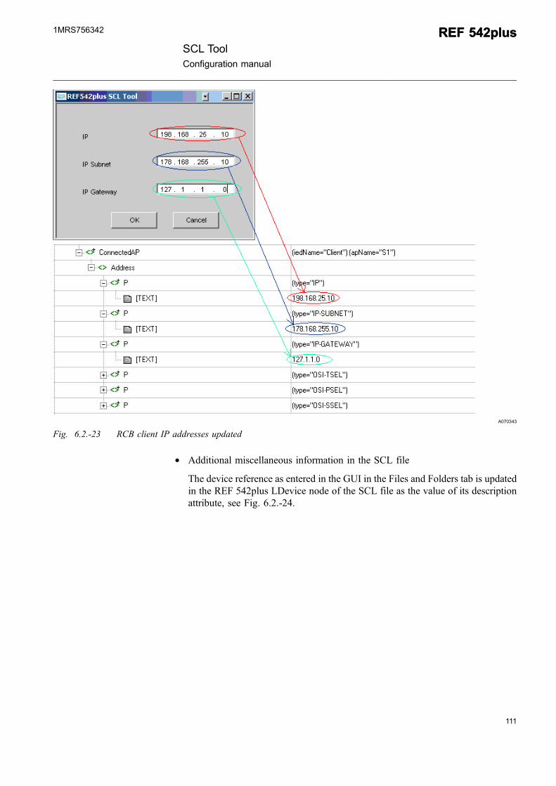
* Import section
When adding the fifth client under an RCB client list, a client node is created.The IP addresses entered are updated in the node as shown in Fig. 6.2.-23.
110
REF 542plusREF 542plusSCL Tool
Configuration manual
1MRS756342
111
A070343
Fig. 6.2.-23 RCB client IP addresses updated
* Additional miscellaneous information in the SCL file
The device reference as entered in the GUI in the Files and Folders tab is updatedin the REF 542plus LDevice node of the SCL file as the value of its descriptionattribute, see Fig. 6.2.-24.
SCL ToolConfiguration manual
REF 542plusREF 542plus1MRS756342
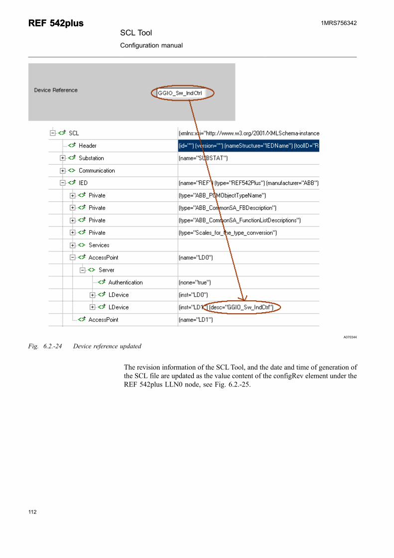
A070344
Fig. 6.2.-24 Device reference updated
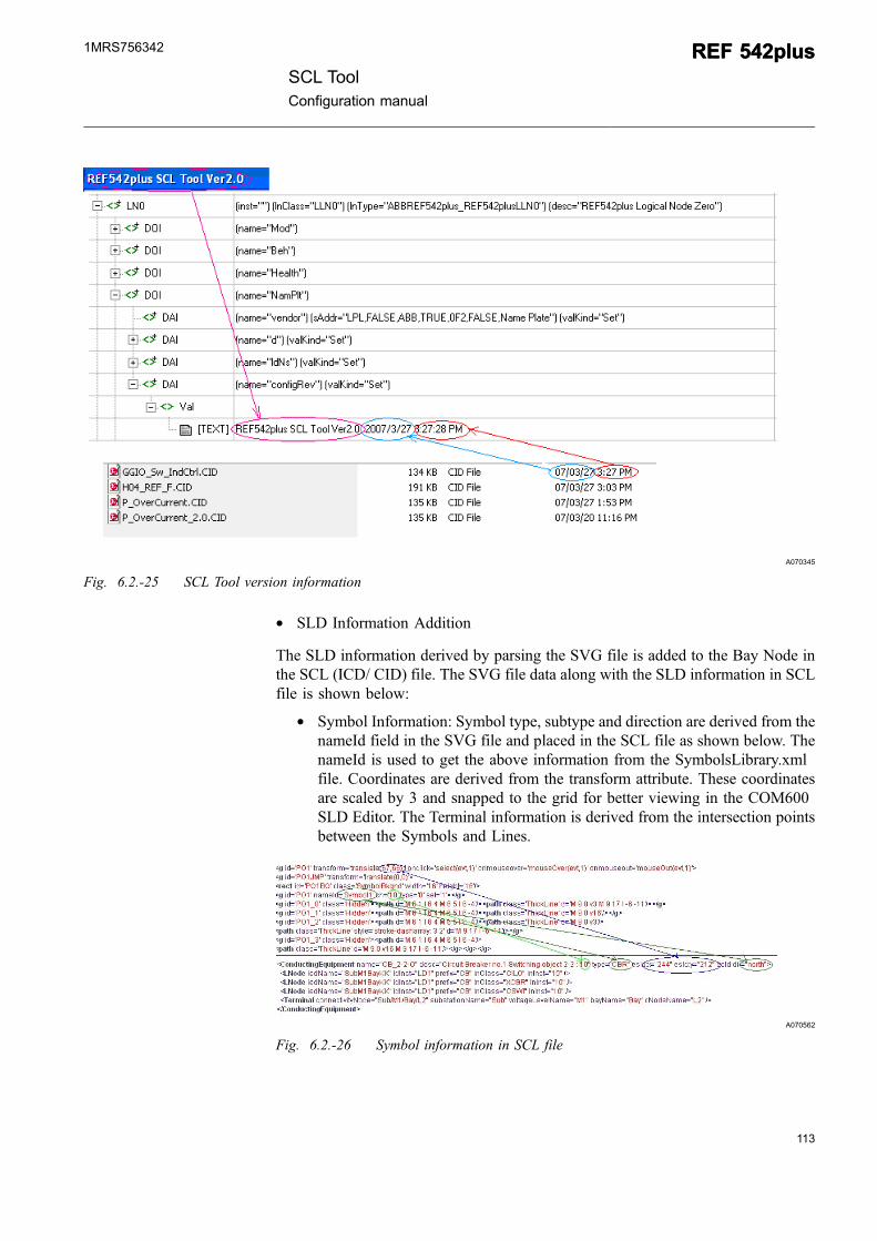
The revision information of the SCLTool, and the date and time of generation ofthe SCL file are updated as the value content of the configRev element under theREF 542plus LLN0 node, see Fig. 6.2.-25.
112
REF 542plusREF 542plusSCL Tool
Configuration manual
1MRS756342
113
A070345
Fig. 6.2.-25 SCL Tool version information
* SLD Information Addition
The SLD information derived by parsing the SVG file is added to the Bay Node inthe SCL (ICD/ CID) file. The SVG file data along with the SLD information in SCLfile is shown below:
* Symbol Information: Symbol type, subtype and direction are derived from thenameId field in the SVG file and placed in the SCL file as shown below. ThenameId is used to get the above information from the SymbolsLibrary.xmlfile. Coordinates are derived from the transform attribute. These coordinatesare scaled by 3 and snapped to the grid for better viewing in the COM600SLD Editor. The Terminal information is derived from the intersection pointsbetween the Symbols and Lines.
A070562
Fig. 6.2.-26 Symbol information in SCL file
SCL ToolConfiguration manual
REF 542plusREF 542plus1MRS756342
* Text Information: Text to be displayed and the coordinates are derived for anAnnotation as shown in Fig. 6.2.-27. Here, too, the coordinates are scaled andthen snapped to grid for better viewing in the COM600 SLD Editor.
A070563
Fig. 6.2.-27 Annotation information in SCL file.
* ConnectivityNode Information: ConnectivityNode’s coordinates aredetermined from the Intersection points and then added to the SCL File asshown in Fig. 6.2.-28.
A070564
Fig. 6.2.-28 ConnectivityNode information in SCL file
A070565
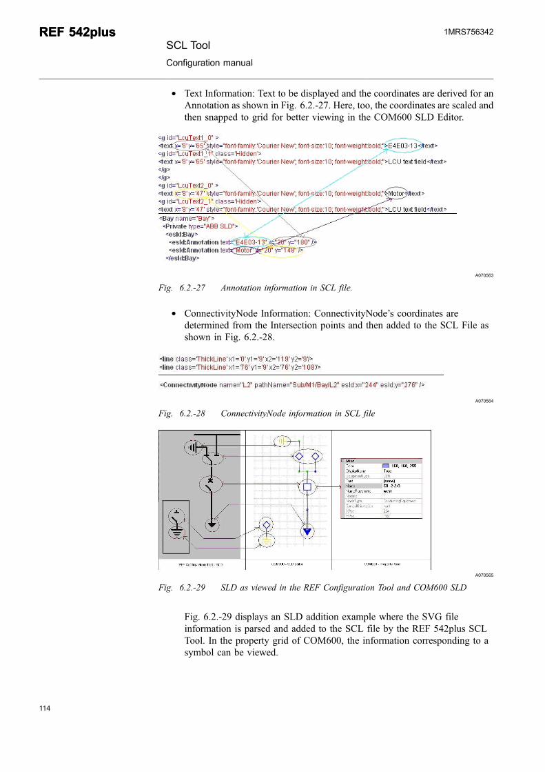
Fig. 6.2.-29 SLD as viewed in the REF Configuration Tool and COM600 SLD
Fig. 6.2.-29 displays an SLD addition example where the SVG fileinformation is parsed and added to the SCL file by the REF 542plus SCLTool. In the property grid of COM600, the information corresponding to asymbol can be viewed.
114
REF 542plusREF 542plusSCL Tool
Configuration manual
1MRS756342
115
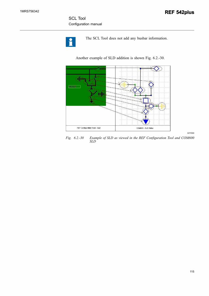
The SCL Tool does not add any busbar information.
Another example of SLD addition is shown Fig. 6.2.-30.
A070566
Fig. 6.2.-30 Example of SLD as viewed in the REF Configuration Tool and COM600SLD
SCL ToolConfiguration manual
REF 542plusREF 542plus1MRS756342

116
117
7. SCL Tool error and exception handling
7.1. Missing files
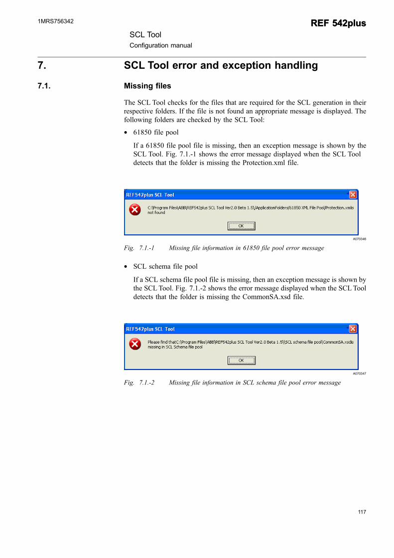
The SCL Tool checks for the files that are required for the SCL generation in theirrespective folders. If the file is not found an appropriate message is displayed. Thefollowing folders are checked by the SCL Tool:
* 61850 file pool
If a 61850 file pool file is missing, then an exception message is shown by theSCL Tool. Fig. 7.1.-1 shows the error message displayed when the SCL Tooldetects that the folder is missing the Protection.xml file.
A070346
Fig. 7.1.-1 Missing file information in 61850 file pool error message
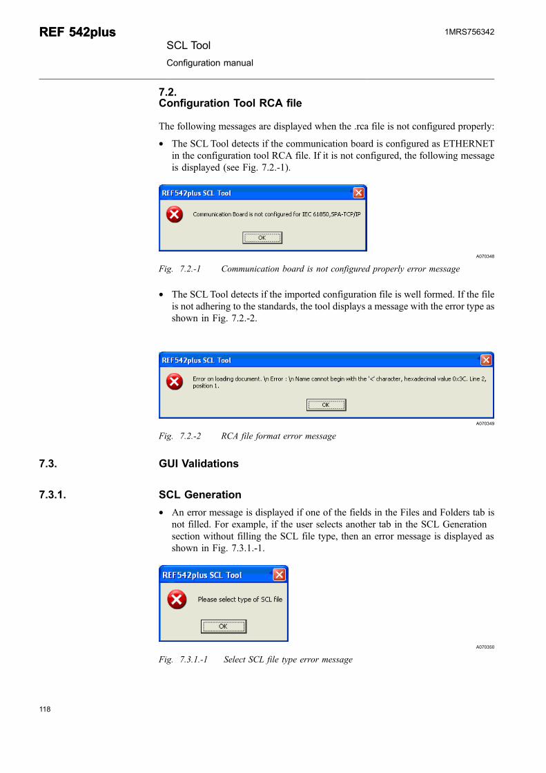
* SCL schema file pool
If a SCL schema file pool file is missing, then an exception message is shown bythe SCL Tool. Fig. 7.1.-2 shows the error message displayed when the SCL Tooldetects that the folder is missing the CommonSA.xsd file.
A070347
Fig. 7.1.-2 Missing file information in SCL schema file pool error message
SCL ToolConfiguration manual
REF 542plusREF 542plus1MRS756342
7.2.Configuration Tool RCA file
The following messages are displayed when the .rca file is not configured properly:
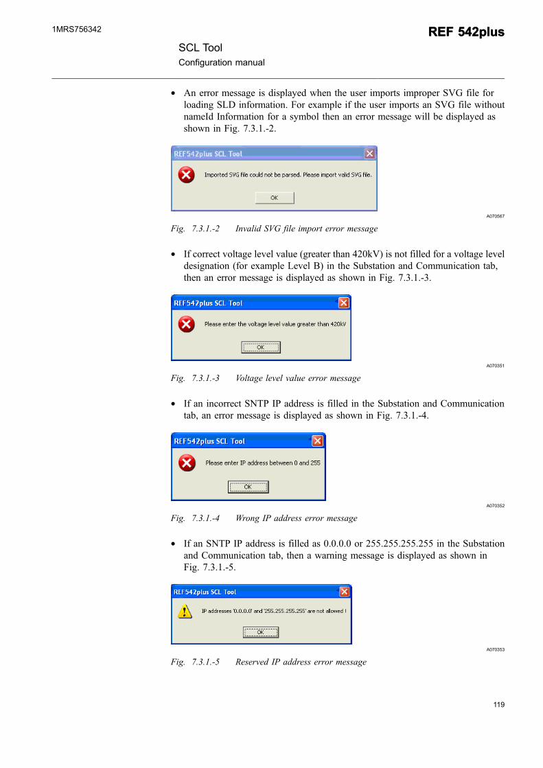
* The SCL Tool detects if the communication board is configured as ETHERNETin the configuration tool RCA file. If it is not configured, the following messageis displayed (see Fig. 7.2.-1).
A070348
Fig. 7.2.-1 Communication board is not configured properly error message
* The SCLTool detects if the imported configuration file is well formed. If the fileis not adhering to the standards, the tool displays a message with the error type asshown in Fig. 7.2.-2.
A070349
Fig. 7.2.-2 RCA file format error message
7.3. GUI Validations
7.3.1. SCL Generation
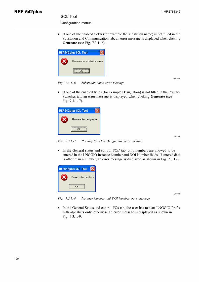
* An error message is displayed if one of the fields in the Files and Folders tab isnot filled. For example, if the user selects another tab in the SCL Generationsection without filling the SCL file type, then an error message is displayed asshown in Fig. 7.3.1.-1.
A070350
Fig. 7.3.1.-1 Select SCL file type error message
118
REF 542plusREF 542plusSCL Tool
Configuration manual
1MRS756342
119
* An error message is displayed when the user imports improper SVG file forloading SLD information. For example if the user imports an SVG file withoutnameId Information for a symbol then an error message will be displayed asshown in Fig. 7.3.1.-2.
A070567
Fig. 7.3.1.-2 Invalid SVG file import error message
* If correct voltage level value (greater than 420kV) is not filled for a voltage leveldesignation (for example Level B) in the Substation and Communication tab,then an error message is displayed as shown in Fig. 7.3.1.-3.
A070351
Fig. 7.3.1.-3 Voltage level value error message
* If an incorrect SNTP IP address is filled in the Substation and Communicationtab, an error message is displayed as shown in Fig. 7.3.1.-4.
A070352
Fig. 7.3.1.-4 Wrong IP address error message
* If an SNTP IP address is filled as 0.0.0.0 or 255.255.255.255 in the Substationand Communication tab, then a warning message is displayed as shown inFig. 7.3.1.-5.
A070353
Fig. 7.3.1.-5 Reserved IP address error message
SCL ToolConfiguration manual
REF 542plusREF 542plus1MRS756342
* If one of the enabled fields (for example the substation name) is not filled in theSubstation and Communication tab, an error message is displayed when clickingGenerate (see Fig. 7.3.1.-6).
A070354
Fig. 7.3.1.-6 Substation name error message
* If one of the enabled fields (for example Designation) is not filled in the PrimarySwitches tab, an error message is displayed when clicking Generate (seeFig. 7.3.1.-7).
A070355
Fig. 7.3.1.-7 Primary Switches Designation error message
* In the General status and control I/Os’ tab, only numbers are allowed to beentered in the LNGGIO Instance Number and DOI Number fields. If entered datais other than a number, an error message is displayed as shown in Fig. 7.3.1.-8.
A070356
Fig. 7.3.1.-8 Instance Number and DOI Number error message
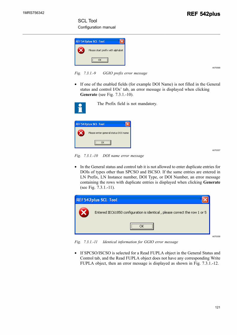
* In the General Status and control I/Os tab, the user has to start LNGGIO Prefixwith alphabets only, otherwise an error message is displayed as shown inFig. 7.3.1.-9.
120
REF 542plusREF 542plusSCL Tool
Configuration manual
1MRS756342
121
A070568
Fig. 7.3.1.-9 GGIO prefix error message
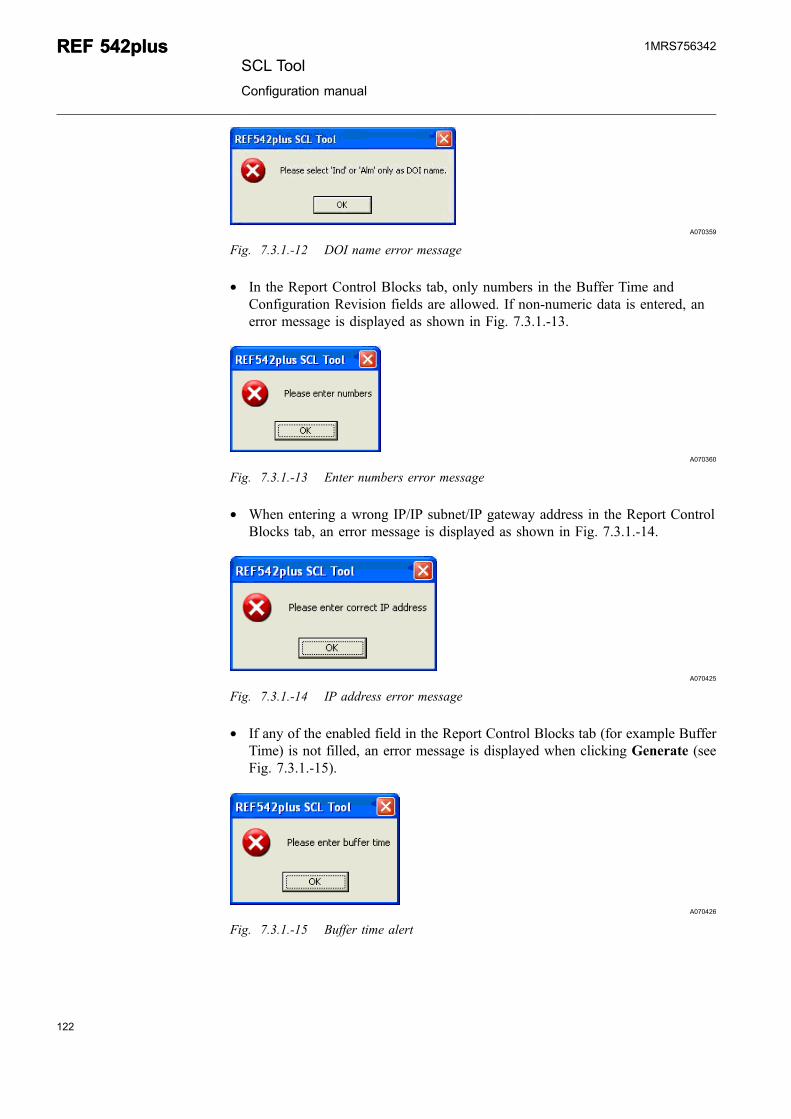
* If one of the enabled fields (for example DOI Name) is not filled in the Generalstatus and control I/Os’ tab, an error message is displayed when clickingGenerate (see Fig. 7.3.1.-10).
The Prefix field is not mandatory.
A070357
Fig. 7.3.1.-10 DOI name error message
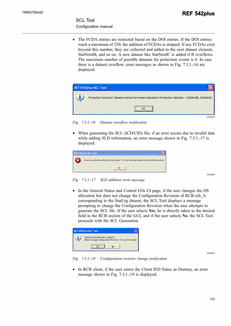
* In the General status and control tab it is not allowed to enter duplicate entries forDOIs of types other than SPCSO and ISCSO. If the same entries are entered inLN Prefix, LN Instance number, DOI Type, or DOI Number, an error messagecontaining the rows with duplicate entries is displayed when clicking Generate(see Fig. 7.3.1.-11).
A070358
Fig. 7.3.1.-11 Identical information for GGIO error message
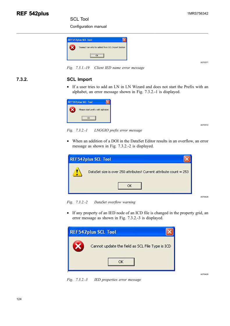
* If SPCSO/ISCSO is selected for a Read FUPLA object in the General Status andControl tab, and the Read FUPLA object does not have any corresponding WriteFUPLA object, then an error message is displayed as shown in Fig. 7.3.1.-12.
SCL ToolConfiguration manual
REF 542plusREF 542plus1MRS756342
A070359
Fig. 7.3.1.-12 DOI name error message
* In the Report Control Blocks tab, only numbers in the Buffer Time andConfiguration Revision fields are allowed. If non-numeric data is entered, anerror message is displayed as shown in Fig. 7.3.1.-13.
A070360
Fig. 7.3.1.-13 Enter numbers error message
* When entering a wrong IP/IP subnet/IP gateway address in the Report ControlBlocks tab, an error message is displayed as shown in Fig. 7.3.1.-14.
A070425
Fig. 7.3.1.-14 IP address error message
* If any of the enabled field in the Report Control Blocks tab (for example BufferTime) is not filled, an error message is displayed when clicking Generate (seeFig. 7.3.1.-15).
A070426
Fig. 7.3.1.-15 Buffer time alert
122
REF 542plusREF 542plusSCL Tool
Configuration manual
1MRS756342
123
* The FCDA entries are restricted based on the DOI entries. If the DOI entriesreach a maximum of 250, the addition of FCDAs is stopped. If any FCDAs existbeyond this number, they are collected and added to the next dataset element,StatNrmlB, and so on. A new dataset like StatNrmlC is added if B overflows.The maximum number of possible datasets for protection events is 6. In casethere is a dataset overflow, error messages as shown in Fig. 7.3.1.-16 aredisplayed.
A070427
Fig. 7.3.1.-16 Dataset owerflow notification
* When generating the SCL (ICD/CID) file, if an error occurs due to invalid datawhile adding SLD information, an error message shown in Fig. 7.3.1.-17 isdisplayed.
A070569
Fig. 7.3.1.-17 SLD addition error message
* In the General Status and Control I/Os UI page, if the user changes the DSallocation but does not change the Configuration Revision of RCB rcb_Acorresponding to the StatUrg dataset, the SCL Tool displays a messageprompting to change the Configuration Revision when the user attempts togenerate the SCL file. If the user selects Yes, he is directly taken to the desiredfield in the RCB section of the GUI, and if the user selects No, the SCL Toolproceeds with the SCL Generation.
A070570
Fig. 7.3.1.-18 Configuration revision change notification
* In RCB client, if the user enters the Client IED Name as Dummy, an errormessage shown in Fig. 7.3.1.-19 is displayed.
SCL ToolConfiguration manual
REF 542plusREF 542plus1MRS756342
A070571
Fig. 7.3.1.-19 Client IED name error message
7.3.2. SCL Import
* If a user tries to add an LN in LN Wizard and does not start the Prefix with analphabet, an error message shown in Fig. 7.3.2.-1 is displayed.
A070572
Fig. 7.3.2.-1 LNGGIO prefix error message
* When an addition of a DOI in the DataSet Editor results in an overflow, an errormessage as shown in Fig. 7.3.2.-2 is displayed.
A070428
Fig. 7.3.2.-2 DataSet overflow warning
* If any property of an IED node of an ICD file is changed in the property grid, anerror message as shown in Fig. 7.3.2.-3 is displayed.
A070429
Fig. 7.3.2.-3 IED properties error message
124
REF 542plusREF 542plusSCL Tool
Configuration manual
1MRS756342
125
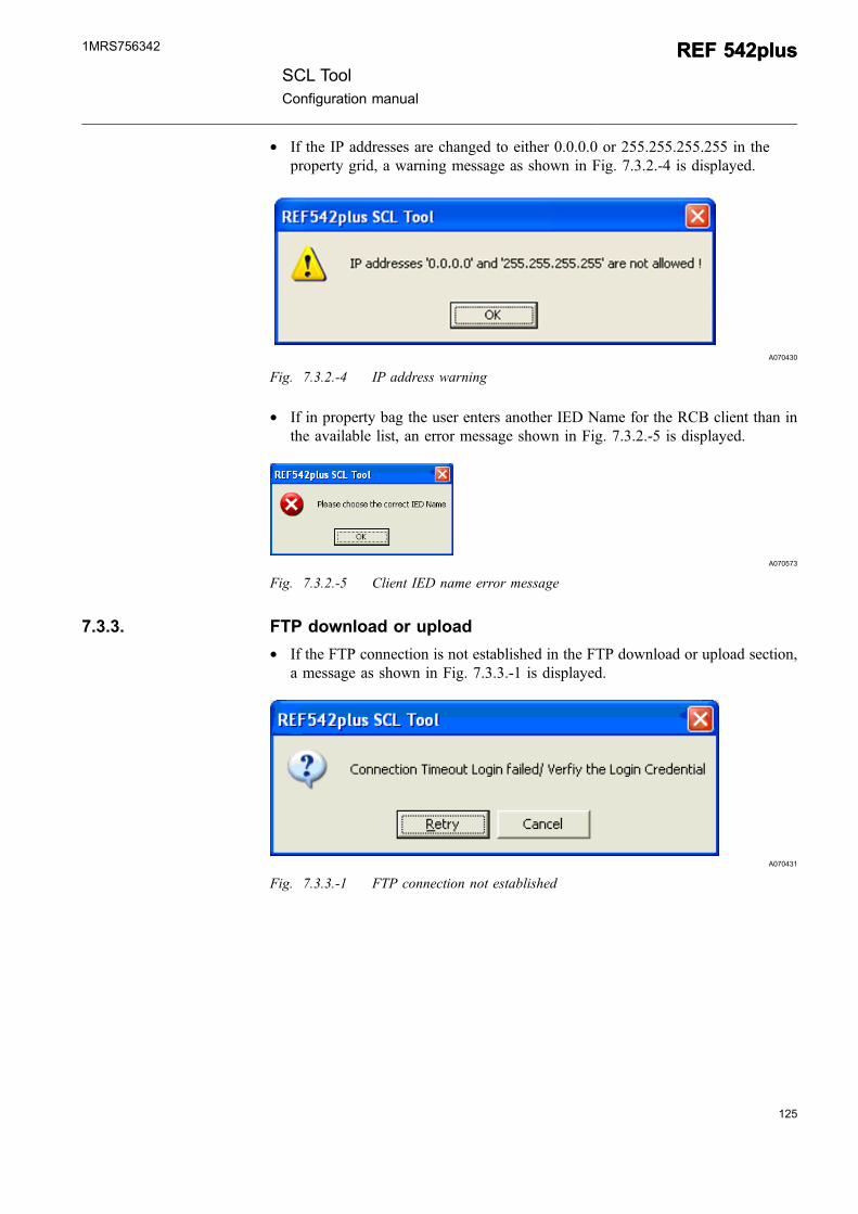
* If the IP addresses are changed to either 0.0.0.0 or 255.255.255.255 in theproperty grid, a warning message as shown in Fig. 7.3.2.-4 is displayed.
A070430
Fig. 7.3.2.-4 IP address warning
* If in property bag the user enters another IED Name for the RCB client than inthe available list, an error message shown in Fig. 7.3.2.-5 is displayed.
A070573
Fig. 7.3.2.-5 Client IED name error message
7.3.3. FTP download or upload
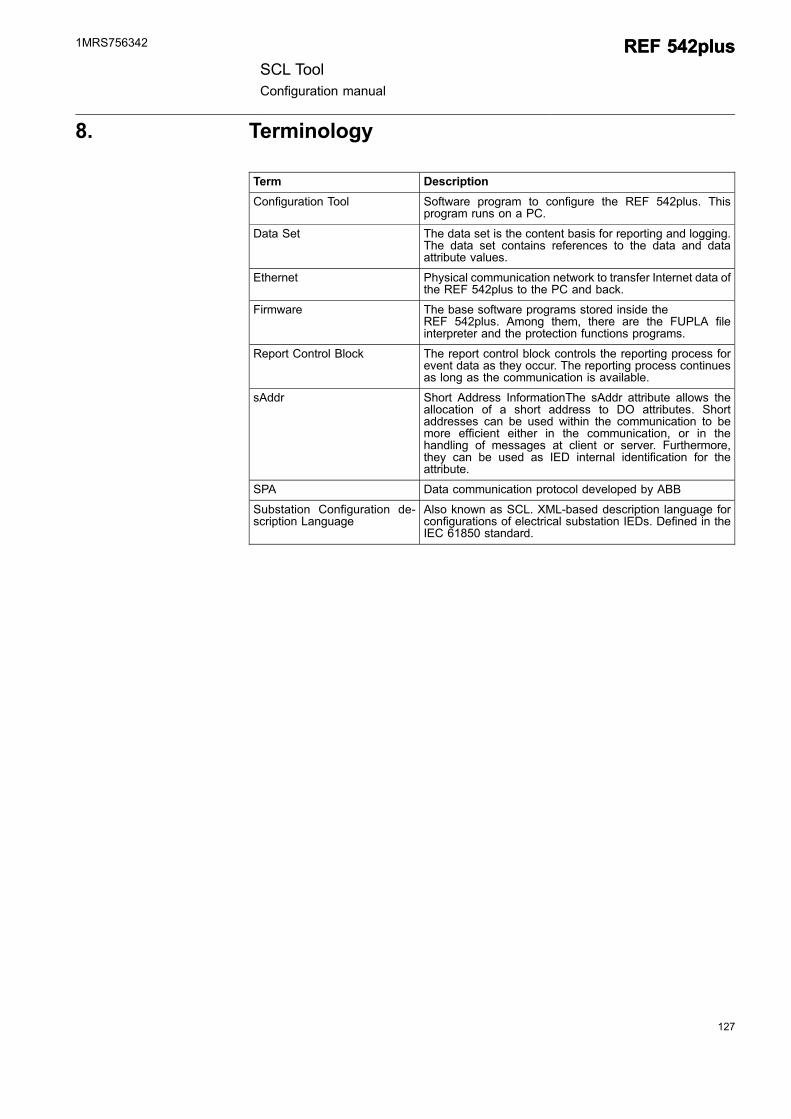
* If the FTP connection is not established in the FTP download or upload section,a message as shown in Fig. 7.3.3.-1 is displayed.
A070431
Fig. 7.3.3.-1 FTP connection not established
SCL ToolConfiguration manual
REF 542plusREF 542plus1MRS756342

126
127
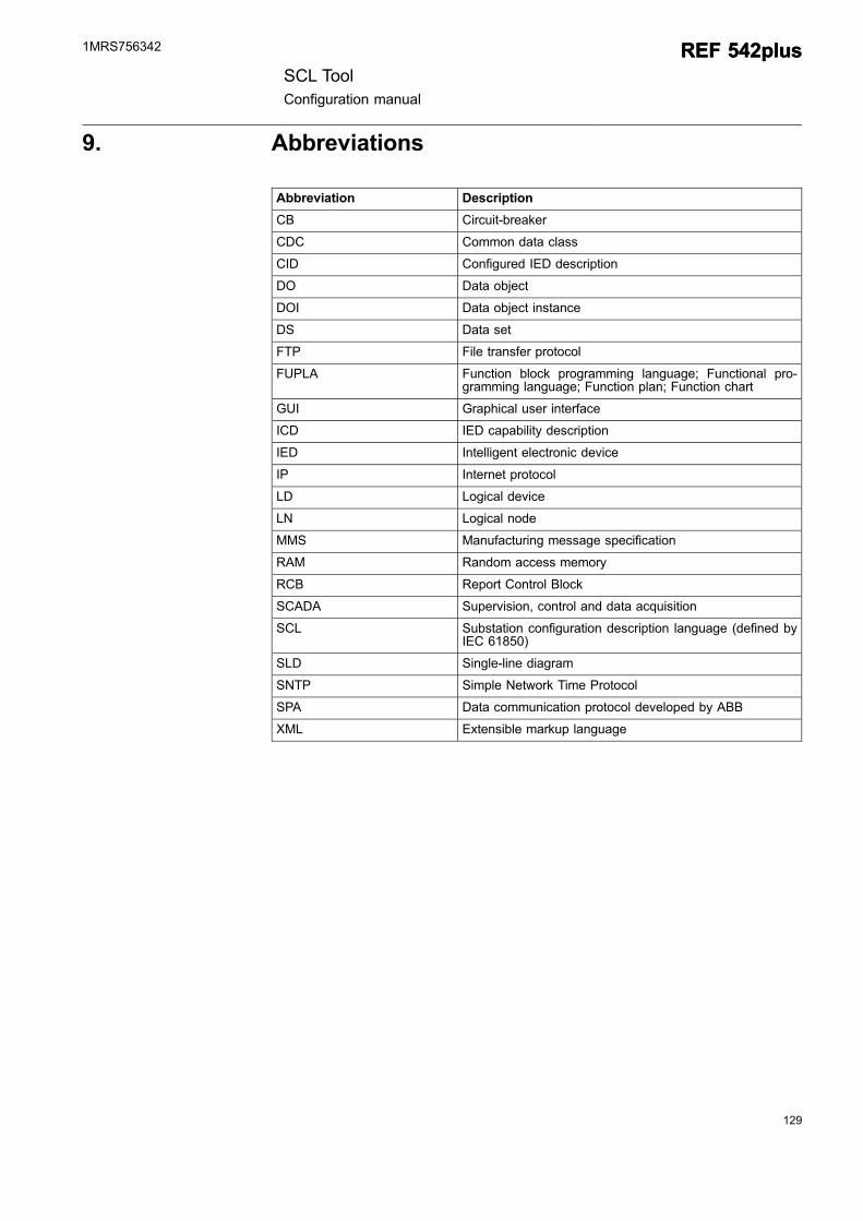
8. Terminology
Term Description
Configuration Tool Software program to configure the REF 542plus. Thisprogram runs on a PC.
Data Set The data set is the content basis for reporting and logging.The data set contains references to the data and dataattribute values.
Ethernet Physical communication network to transfer Internet data ofthe REF 542plus to the PC and back.
Firmware The base software programs stored inside theREF 542plus. Among them, there are the FUPLA fileinterpreter and the protection functions programs.
Report Control Block The report control block controls the reporting process forevent data as they occur. The reporting process continuesas long as the communication is available.
sAddr Short Address InformationThe sAddr attribute allows theallocation of a short address to DO attributes. Shortaddresses can be used within the communication to bemore efficient either in the communication, or in thehandling of messages at client or server. Furthermore,they can be used as IED internal identification for theattribute.
SPA Data communication protocol developed by ABB
Substation Configuration de-scription Language
Also known as SCL. XML-based description language forconfigurations of electrical substation IEDs. Defined in theIEC 61850 standard.
SCL ToolConfiguration manual
REF 542plusREF 542plus1MRS756342

128
129
9. Abbreviations
Abbreviation Description
CB Circuit-breaker
CDC Common data class
CID Configured IED description
DO Data object
DOI Data object instance
DS Data set
FTP File transfer protocol
FUPLA Function block programming language; Functional pro-gramming language; Function plan; Function chart
GUI Graphical user interface
ICD IED capability description
IED Intelligent electronic device
IP Internet protocol
LD Logical device
LN Logical node
MMS Manufacturing message specification
RAM Random access memory
RCB Report Control Block
SCADA Supervision, control and data acquisition
SCL Substation configuration description language (defined byIEC 61850)
SLD Single-line diagram
SNTP Simple Network Time Protocol
SPA Data communication protocol developed by ABB
XML Extensible markup language
SCL ToolConfiguration manual
REF 542plusREF 542plus1MRS756342


ABB OyDistribution AutomationP.O. Box 699FI-65101 VaasaFINLAND+358 10 22 11+358 10 22 224 1094http://www.abb.com/substationautomation
1MRS756342
EN
5/2007