Motor Protection with ATEX Certification User´s guide 1. Introduction 1.1. This manual This part of...
88
REF 542plus REF 542plus Motor Protection with ATEX - Certification User´s guide
Transcript of Motor Protection with ATEX Certification User´s guide 1. Introduction 1.1. This manual This part of...

REF 542plusREF 542plus
Motor Protection with ATEX − Certification
User´s guide


3
Contents
Copyrights ................................................................................. 7
1. Introduction..............................................................91.1. This manual .............................................................. 91.2. Use of symbols ......................................................... 91.3. Intended audience ................................................... 101.4. Product documentation ............................................. 101.5. Document revisions...................................................11
2. Safety information...................................................13
3. Motor protection functions.......................................153.1. Supervision of a blocking rotor ................................... 16
3.1.1. Setting parameters....................................... 163.1.2. Functional check.......................................... 17
3.2. Motor start protection................................................ 173.2.1. Setting parameters....................................... 183.2.2. Tripping characteristic................................... 193.2.3. Functional check.......................................... 21
3.3. Number of starts protection ....................................... 213.3.1. Setting parameters....................................... 213.3.2. Functional check.......................................... 23
3.4. Thermal overload protection ...................................... 233.4.1. Setting parameters....................................... 26
3.4.1.1. Setting the time constant ................ 273.4.1.2. Setting the temperature .................. 283.4.1.3. Behavior during powering on and
off ............................................... 293.4.1.4. Setting the temperature after reset ... 29
3.4.2. Tripping characteristic................................... 303.4.3. Functional check.......................................... 32
3.5. Unbalanced load protection ....................................... 323.5.1. Setting parameters....................................... 33
3.5.1.1. Setting the current starting value...... 343.5.1.2. Setting the tripping time.................. 34
3.5.2. Tripping characteristic................................... 353.5.3. Functional check.......................................... 37
4. Setting example ......................................................394.1. Rotor block protection............................................... 404.2. Motor start protection................................................ 404.3. Thermal overload protection ...................................... 404.4. Number of starts protection ....................................... 424.5. Tripping characteristic............................................... 434.6. Behavior after recovering of the auxiliary voltage .......... 44
Multifunction Protection and Switchgear ControlUnit
Motor Protection with ATEX − Certification
User´s guide
REF 542plusREF 542plus1MRS755862
Issued: 06.12.2002Version: C/04.12.2009
5. Operation of the REF 542plus ..................................475.1. Operator's responsibilities.......................................... 475.2. Guarantee Provisions ............................................... 475.3. Safety Regulations................................................... 48
5.3.1. General safety notes .................................... 485.3.2. Specific safety information............................. 495.3.3. Risk analysis and safety measures ................. 50
6. Mounting and Installation ........................................516.1. Unpacking .............................................................. 516.2. Mounting ................................................................ 51
6.2.1. Set-up Area and Required EnvironmentalConditions .................................................. 54
6.2.2. Installation in LV panels ................................ 556.2.3. Wiring REF 542plus ..................................... 56
6.2.3.1. Checking the current transformercircuits......................................... 57
6.2.3.2. Checking the voltage transformercircuits......................................... 57
6.2.3.3. Checking the auxiliary voltage ......... 586.2.3.4. Checking the tripping and signaling
contacts ....................................... 586.2.3.5. Checking the binary inputs.............. 58
6.2.4. Grounding of REF 542plus ............................ 586.2.5. Typical examples of analog and binary
connections ................................................ 596.2.6. Connection example of the REF 542plus
analog inputs .............................................. 60
7. Commissioning.......................................................637.1. Safety Information.................................................... 637.2. Switching on the feeder ............................................ 637.3. Test equipment........................................................ 637.4. Testing the interlock conditions................................... 637.5. Determining the transformer direction .......................... 63
7.5.1. Current transformer ...................................... 647.5.2. Voltage transformer ...................................... 657.5.3. Current sensor ............................................ 657.5.4. Voltage sensor ............................................ 66
7.6. Testing the measured value recording ......................... 667.7. Testing the protective functions .................................. 67
8. Technical data ........................................................698.1. Analog inputs .......................................................... 69
4
REF 542plusREF 542plus Multifunction Protection and Switchgear ControlUnit
Motor Protection with ATEX − Certification
User´s guide
1MRS755862
5
8.1.1. Measurements ............................................ 698.1.2. Protection ................................................... 69
8.2. Binary inputs and outputs.......................................... 708.2.1. BIO module with mechanical output relays
(version 3) .................................................. 708.3. Binary inputs and outputs.......................................... 70
8.3.1. BIO module with mechanical output relays(version3) ................................................... 71
8.3.2. BIO module with static outputs....................... 728.4. Interfaces ............................................................... 728.5. Power supply .......................................................... 748.6. Environmental conditions .......................................... 748.7. Protection degree .................................................... 74
9. Abbreviations .........................................................75
Appendix A: Thermal overload protection .....................77
Multifunction Protection and Switchgear ControlUnit
Motor Protection with ATEX − Certification
User´s guide
REF 542plusREF 542plus1MRS755862

6
7
CopyrightsThe information in this document is subject to change without notice and should notbe construed as a commitment by ABB Oy. ABB Oy assumes no responsibility forany errors that may appear in this document.
In no event shall ABB Oy be liable for direct, indirect, special, incidental orconsequential damages of any nature or kind arising from the use of this document,nor shall ABB Oy be liable for incidental or consequential damages arising fromthe use of any software or hardware described in this document.
This document and parts thereof must not be reproduced or copied without writtenpermission from ABB Oy, and the contents thereof must not be imparted to a thirdparty nor used for any unauthorized purpose.
The software or hardware described in this document is furnished under a licenseand may be used, copied or disclosed only in accordance with the terms of suchlicense.
© Copyright 2009 ABB Oy
All rights reserved.
Trademarks
ABB is a registered trademark of ABB Group. All other brand or product namesmentioned in this document may be trademarks or registered trademarks of theirrespective holders.
Guarantee
Please inquire about the terms of guarantee from your nearest ABB representative.
Multifunction Protection and Switchgear ControlUnit
Motor Protection with ATEX − Certification
User´s guide
REF 542plusREF 542plus1MRS755862

8

9
1. Introduction
1.1. This manual
This part of the manual for the multifunctional protection and switchbay control unitREF 542plus primarily focuses on the integrated motor protection functions. Sectionand its subsections contain information on:
* The basic principle of functioning* Setting of the parameters* Representation of the tripping characteristic
CE Conformity Declaration
Multifunctional Protection and Bay Control Unit REF 542plus is designed andmanufactured complying to the corresponding international standards of the seriesEN 50081, EN 50082 for EMC-Guidelines and EN 60255-6 for Low VoltageDirective of the European Parliament and Council.
1.2. Use of symbols
This publication includes the following icons that point out safety-related conditionsor other important information:
The electrical warning icon indicates the presence of a hazard whichcould result in electrical shock.
The warning icon indicates the presence of a hazard which could resultin personal injury.
The caution icon indicates important information or warning related tothe concept discussed in the text. It might indicate the presence of ahazard which could result in corruption of software or damage toequipment or property.
The information icon alerts the reader to relevant facts and conditions.
Although warning hazards are related to personal injury, it should be understoodthat operation of damaged equipment could, under certain operational conditions,result in degraded process performance leading to personal injury or death.Therefore, comply fully with all warning and caution notices.
Multifunction Protection and Switchgear ControlUnit
Motor Protection with ATEX − Certification
User´s guide
REF 542plusREF 542plus1MRS755862

1.3. Intended audience
This manual is intended for engineers to support configuration and engineering ofsystems and/or applications.
1.4. Product documentation
Name of the Manual Document ID
Real-time clock synchronization, IRIG-B input time master 1MRS755870
CAN Manual 1VTA100189-Rev 1, en
Configuration Manual 1MRS755871
iButton Programmer User Manual 1MRS755863
Manual Part 3, Installation and Commission 1VTA100004
Manual Part 4, Communication 1VTA100005
Motor Protection with ATEX Certification, Manual 1MRS755862
Operator’s Manual 1MRS755869
Protection Manual 1MRS755860
REF542plus: Risikoanalyse und sicherheitsgerichtetesVerhalten
1VTA300137
Technical Reference Manual 1MRS755859
Technical Reference Modbus RTU 1MRS755868
Web Manual, Installation 1MRS755865
Web Manual, Operation 1MRS755864
Other related documents
[IEC01] IEC 60255-8: Thermal electrical relays, 2nd edition, 1990-09.
[IEC02] IEC 60079-7: Explosive atmospheres – Part 7: Equipment protection byincreased safety "e," 2006-07.
[IEC03] IEC60085: Electrical insulation – Thermal classification, 2004-06.
[AT 01] Directive 94/9/EC: Directive to be applied to equipment and protectivesystems intended for use in potentially explosive atmospheres, 23 March1994.
[AT 02] Guidelines on the application of council directive 94/9/ec of 23 March1994 on the approximation of the laws of the member states concerningequipment and protective systems intended for use in potentiallyexplosive atmospheres, May 2000.
[AT 03] Production Quality Assessment Notification, PTB 03 ATEX Q07,Equipment or protective systems or components intended for use inpotentially explosive atmospheres – Directive 94/9/EC, Motor ProtectionDevice, November 2003.
10
REF 542plusREF 542plus Multifunction Protection and Switchgear ControlUnit
Motor Protection with ATEX − Certification
User´s guide
1MRS755862

11
1.5. Document revisions
Version IED Revisionnumber
Date History
1VTA100114-Rev02 en 06.12.2002 Document created
1VTA100114-Rev05 en 2.0 01.07.2005 Updated to version V4D02x
A 28.02.2006 Document updated* language* layout
B 2.0 30.09.2006 Equations updated
C 2.5 SP3 4.12.2009 Updated to version V4E04c
Applicability
This manual is applicable to the REF 542plus release 2.5 SP3, software versionV4E04c.
Multifunction Protection and Switchgear ControlUnit
Motor Protection with ATEX − Certification
User´s guide
REF 542plusREF 542plus1MRS755862

12

13
2. Safety information
Dangerous voltages can occur on the connectors, even though theauxiliary voltage has been disconnected.
Non-observance can result in death, personal injury or substantialproperty damage.
Only a competent electrician is allowed to carry out the electricalinstallation.
National and local electrical safety regulations must always befollowed.
The frame of the device has to be carefully earthed.
The device contains components which are sensitive to electrostaticdischarge. Unnecessary touching of electronic components musttherefore be avoided.
Multifunction Protection and Switchgear ControlUnit
Motor Protection with ATEX − Certification
User´s guide
REF 542plusREF 542plus1MRS755862

14

15
3. Motor protection functionsOverloading conditions cause impermissible temperature rises in motors and mayresult in premature fatigue and aging. If this type of condition persists, thermaldestruction of the components cannot be excluded.
With regard to the protection functions, a distinction has to be made betweenoverloads caused by starting processes and overloads occurring during operation.During startup, both in the winding of the rotor and in the winding of the stator,currents may be present that are well above regular on-load currents. A fast trippingmust be generated in case a disturbance does occur during startup, for instance, inthe event of a rotor block or motor start under heavy load condition. To preventoverloading conditions, also the number of starts needs to be limited.
While the motor is running, overloads may occur as a result of the working loads.For monitoring such operating conditions, the temperature is calculated on the basisof a thermal model.
For motor protection purposes, the REF 542plus field control and protection deviceincludes the following functions:
During the starting process
* Blocking rotor protection* Motor start protection* Number of starts protection
During operation
* Thermal overload protection* Unbalanced load protection or optionally a simple positive sequence monitoring
In all cases, the momentary motor temperature is crucial for the motor protectionfunctions. The REF 542plus uses a common thermal replica of the first order fordetermining the motor temperature. Consequently, decisions can be taken by allapplied protection functions, depending on the momentary value of the calculatedmotor temperature.
The thermal replica referred to above is started immediately, as soon as the currentflows through the motor windings. Thus, the motor protection in the REF 542plus isdesigned as an thermal overload protection with a total memory function inaccordance with standard IEC 60255 − 8 [DIN1], since a previous loading conditionis always taken into consideration and is being tracked by the thermal replica.
Unbalanced load protection is provided as a phase failure protection caused by anopen-circuit condition (broken phase connection). This type of protection enablesmonitoring of the negative-sequence component which causes a temperature rise inthe laminated core of the rotor. Optionally, in case of small motors a simple positivesequence monitoring function can be applied instead.
Multifunction Protection and Switchgear ControlUnit
Motor Protection with ATEX − Certification
User´s guide
REF 542plusREF 542plus1MRS755862
3.1. Supervision of a blocking rotor
When the rotor is blocked, the current in the motor increases and is determined bythe starting current which magnitude is multiple of the rated motor current. Toprevent a thermal overload, a fast tripping must be generated. The blocking rotor issupervised by a special, overcurrent definite time protection function whichgenerates a tripping signal with settable delay as soon as an adjustable currentthreshold is exceeded.
3.1.1. Setting parameters
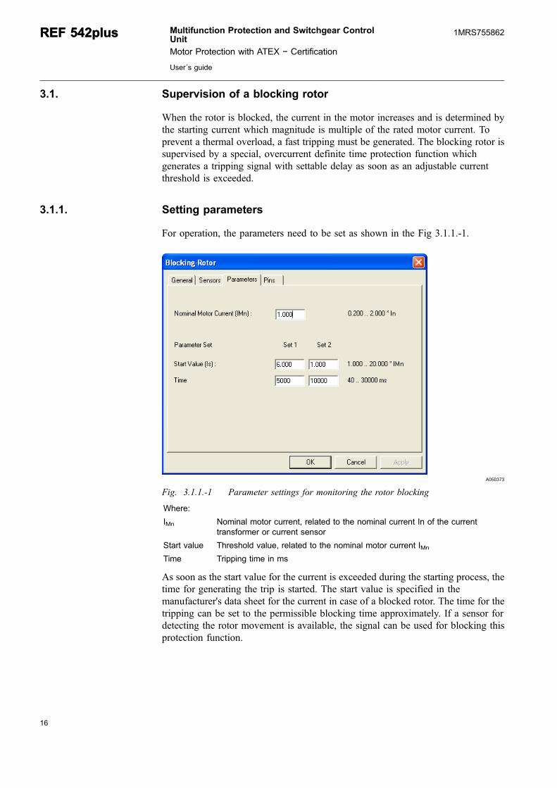
For operation, the parameters need to be set as shown in the Fig 3.1.1.-1.
A050373
Fig. 3.1.1.-1 Parameter settings for monitoring the rotor blocking
Where:
IMn Nominal motor current, related to the nominal current In of the currenttransformer or current sensor
Start value Threshold value, related to the nominal motor current IMn
Time Tripping time in ms
As soon as the start value for the current is exceeded during the starting process, thetime for generating the trip is started. The start value is specified in themanufacturer's data sheet for the current in case of a blocked rotor. The time for thetripping can be set to the permissible blocking time approximately. If a sensor fordetecting the rotor movement is available, the signal can be used for blocking thisprotection function.
16
REF 542plusREF 542plus Multifunction Protection and Switchgear ControlUnit
Motor Protection with ATEX − Certification
User´s guide
1MRS755862
17
3.1.2. Functional check
For checking the blocking rotor monitoring functions, it is recommended to usesingle- or three-phase testing equipment. By varying the test current it is possible toobserve the generation of the start signal and, after the preset time has expired, thetripping signal.
3.2. Motor start protection
Overloading of the motor may occur if the duration of the starting process isextended due to heavy load condition. The startup behavior is impacted by theconnected load. Such overloads are normally more critical for the rotor (rotor-critical motors) than for the stator. Manufacturers of the motor usually specify apermissible start current IA / time tE starting value IA2 tE for their motors.
The current/time starting value is proportional to the thermal short-time loading ofthe motor. It is derived by integrating the current curve i(t) into the time intervalfrom 0 to t:
IA tE i t dtt
2 2
0⋅ = ∫ ( ) (1)
Where:
IA Admissible starting current under heavy load condition
tE Permissible value of the time duration under heavy load condition
i(t) Instantaneous current value
t Time
To simplify the calculation process, it is assumed that the starting current duringheavy startup until the generation of the fast tripping is constant. Under thiscondition, the above equation can be approximated by the equation below:
I t IA tE2 2= (2)
Where:
I Motor startup current
t Motor startup time
The motor start protection function in the REF 542plus can therefore supervise themotor startup behavior for temperature overload conditions using the calculationmethod based on Equation (2). The current/time starting integral is calculated assoon as the preset response value of the starting current is exceeded within the first100 ms during the motor starting process. The tripping signal is generated if thecurrent/time starting integral exceeds the specified value of I2T.
A startup is registered if the motor current changes from values below 0.10 of therated motor current up to values above the preset threshold value of the startingcurrent within 100 ms. The starting signal is reset again as soon as the motor current
Multifunction Protection and Switchgear ControlUnit
Motor Protection with ATEX − Certification
User´s guide
REF 542plusREF 542plus1MRS755862
falls below the preset threshold value of the starting current. If the motor currentdrops below 0.10 of the rated motor current, the motor is assumed to be at standstill.This definition is necessary for determining the thermal model later.
3.2.1. Setting parameters
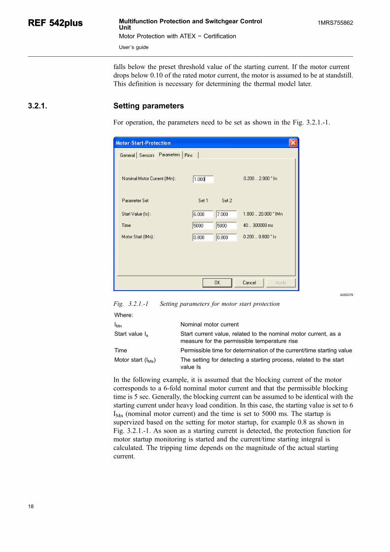
For operation, the parameters need to be set as shown in the Fig. 3.2.1.-1.
A050376
Fig. 3.2.1.-1 Setting parameters for motor start protection
Where:
IMn Nominal motor current
Start value Is Start current value, related to the nominal motor current, as ameasure for the permissible temperature rise
Time Permissible time for determination of the current/time starting value
Motor start (IMs) The setting for detecting a starting process, related to the startvalue Is
In the following example, it is assumed that the blocking current of the motorcorresponds to a 6-fold nominal motor current and that the permissible blockingtime is 5 sec. Generally, the blocking current can be assumed to be identical with thestarting current under heavy load condition. In this case, the starting value is set to 6IMn (nominal motor current) and the time is set to 5000 ms. The startup issupervized based on the setting for motor startup, for example 0.8 as shown inFig. 3.2.1.-1. As soon as a starting current is detected, the protection function formotor startup monitoring is started and the current/time starting integral iscalculated. The tripping time depends on the magnitude of the actual startingcurrent.
18
REF 542plusREF 542plus Multifunction Protection and Switchgear ControlUnit
Motor Protection with ATEX − Certification
User´s guide
1MRS755862
19
If, in the example above, a starting current of a 0.8 starting value Is is assumed, thestarting current will be 0.8 x 6 = 4,8 of the rated motor current IMn. A trippingsignal is generated after a time of:
s7.81s8.4
562
2
��t (3)
3.2.2. Tripping characteristic
The tripping characteristic for the motor start protection function can beapproximated in a simplified approach through Equation (4). The current of blockedmotor can be assumed as the same for the starting current. The permissible startuptime can be calculated from the blocking time accordingly. The following curveshows the tripping of the motor startup monitoring at t6IB equal to 5sec, as afunction of I/IB where IB represents the basic current or the rated motor currentrespectively. The tripping characteristic is mostly defined by the expression of t6IB.This way, it is possible to calculate the tripping time as follows:
( )( ) ( )
IIB t
IIB
IIB
2 2
2 26 5
180= = s respectively t =
36 5s s (4)
Multifunction Protection and Switchgear ControlUnit
Motor Protection with ATEX − Certification
User´s guide
REF 542plusREF 542plus1MRS755862

A050379
Table 3.2.2.-1 gives an overview of the times relevant to the tripping characteristicsof the motor startup monitoring.
Table 3.2.2.-1 Tripping time of the motor startup monitoring for t6IB=5s.
I/IB Tripping time in s
1,00 180,00
1,50 80,00
2,00 45,00
2,50 28,80
3,00 20,00
4,00 11,25
5,00 7,20
6,00 5,00
7,00 3,67
8,00 2,81
9,00 2,22
10,00 1,80
20
REF 542plusREF 542plus Multifunction Protection and Switchgear ControlUnit
Motor Protection with ATEX − Certification
User´s guide
1MRS755862
21
3.2.3. Functional check
For checking the motor startup monitoring function, it is recommended to usesingle- or three-phase testing equipment. By varying the test current it is possible todetect the generation of the triggering signal and, after expiration of the time definedby the tripping characteristic, the tripping as well. The tripping time is independentupon single-phase or three-phase current injection.
3.3. Number of starts protection
As a part of the motor protection function, the number of starts protection shallmonitor the startups. In this context, a distinction is made between cold starts andwarm starts. To detect the number of start, the start signal of above mentionedfunction blocks “Block Rotor” and “Motor Start” can be combined together inlogical OR function and connected to the input SI. If the signal on this input changesfrom 0 to 1, the counter will be incremented. The status of the counter will be takenover to the number of warm start, if the temperature of the motor according to thethermal overload protection is exceeded. The permissible numbers which arenormally specified by the motor manufacturer. If this is not the case, it is normally tobe assumed for 2 cold starts and 1 warm start.
Whether the start is a cold start or a warm start depends on the result calculated forthe thermal replica. The temperature from which on the starts are interpreted aswarm restarts can be parameterized. If the calculated temperature is below thisvalue, a cold start is assumed.
Moreover, a reset time is parameterized to obtain the following results:
* If the startup has been successful only a number of permissible attempts, thenumber of starts counted is set back by one (minus one) after the reset time(cooling-off time) has expired.
* When the number of preset starts has been reached, the protection function entersthe so-called start status (START output). This signal can be used to block arestart of the motor. After the reset time is expired, the number of start counterwill be decremented and enable the motor start again.
* If there is another startup, the protection function will generate a trip signalimmediately. The trip signal (TRIP output) will be pending until the reset timehas expired.
3.3.1. Setting parameters
For operation purposes, the parameters need to be set as shown in the following:
Multifunction Protection and Switchgear ControlUnit
Motor Protection with ATEX − Certification
User´s guide
REF 542plusREF 542plus1MRS755862

A050380
Fig. 3.3.1.-1 Setting parameters for thermal protection
Where:
Nws Permissible number of starts in warm condition
Ncs Permissible number of starts in cold condition
Reset time (trst) Time to decrement the counter
Tws Warm start temperature threshold
The settings should be, in accordance to present standard, provided for 1 warm startand 2 cold starts. According to the definition in [IEC02], the temperatures for warmmotor condition can be specified at 100% of the thermal capacity contents of themotor. The thermal capacity content of the motor, in turn, depends on the setting ofthe thermal overload protection.
The thermal capacity content is determined by the setting in the thermal overloadprotection function. For instance, if the settings of this protection function are suchthat the environment temperature is selected to be 40°C and the rated motortemperature is set to 130°C, the entire thermal memory contents is determined bythe difference between these two temperatures. Thus, 90°C corresponds to thermalmemory contents of 100%. If the warm condition has been defined to be 90% of thethermal memory contents, the temperature for the warm start of the motor needs tobe set to
(0.9 x 90°C) + 40°C = 121 °C
22
REF 542plusREF 542plus Multifunction Protection and Switchgear ControlUnit
Motor Protection with ATEX − Certification
User´s guide
1MRS755862

23
3.3.2. Functional check
For checking the function of the monitoring the number of starts, it is recommendedto use three-phase testing equipment for load simulation in the thermal protectionfunction. Depending on the temperature calculated by the thermal protection, thenumber of starts in cold or warm condition can be tested. The functional check ofthe thermal protection is described inSection 3.4. Thermal overload protection .
3.4. Thermal overload protection
For motor protection, the thermal overload protection based on the thermal replica isone of the major functions for supervizing the motor for temperature violations onaccount of overloads during operation. InREF 542plus, a thermal replica with a totalmemory function has been implemented in accordance with the applicable standard[DIN1]. In the following, the thermal replica and the setting options are dealt with.
For simulating the temperature rise in the motor, a thermal homogenous-body modelwith losses is assumed. The following Fig. 3.4.-1 illustrates the principle of themodel.
A050381
Fig. 3.4.-1 Thermal homogenous-body model with losses
On account of the loads present during the operation conditions, the load current inthe motor can be taken as a measure for the quantity of the thermal energy whichfeeds the temperature rise in the motor. The size of the thermal energy isproportional to the square value of the load current. Due to the existing motorcooling, a portion of the thermal energy will be discharged in the form of energyloss. The rest of the thermal energy is stored in the motor. The size of the storedenergy is proportional to the motor temperature.
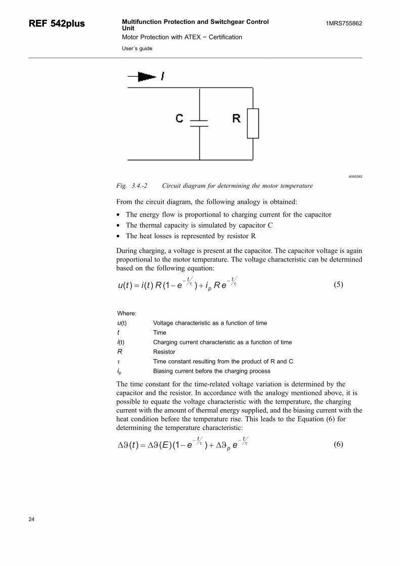
For calculating the motor temperature, the above-mentioned thermal model can besimulated by a simple electrical circuit. The following Fig. 3.4.-2 shows the circuitdiagram.
Multifunction Protection and Switchgear ControlUnit
Motor Protection with ATEX − Certification
User´s guide
REF 542plusREF 542plus1MRS755862
A050382
Fig. 3.4.-2 Circuit diagram for determining the motor temperature
From the circuit diagram, the following analogy is obtained:
* The energy flow is proportional to charging current for the capacitor* The thermal capacity is simulated by capacitor C* The heat losses is represented by resistor R
During charging, a voltage is present at the capacitor. The capacitor voltage is againproportional to the motor temperature. The voltage characteristic can be determinedbased on the following equation:
��t
p
t
eRieRtitu��
��� )1()()( (5)
Where:
u(t) Voltage characteristic as a function of time
t Time
i(t) Charging current characteristic as a function of time
R Resistor
τ Time constant resulting from the product of R and C
ip Biasing current before the charging process
The time constant for the time-related voltage variation is determined by thecapacitor and the resistor. In accordance with the analogy mentioned above, it ispossible to equate the voltage characteristic with the temperature, the chargingcurrent with the amount of thermal energy supplied, and the biasing current with theheat condition before the temperature rise. This leads to the Equation (6) fordetermining the temperature characteristic:
�� ���t
p
t
eeEt��
������ )1()()( (6)
24
REF 542plusREF 542plus Multifunction Protection and Switchgear ControlUnit
Motor Protection with ATEX − Certification
User´s guide
1MRS755862
25
Where:
Δϑ(E) Time-related characteristic of the temperature change during temperature rise
t Time
E Heat energy supplied
Δϑp State of the temperature before temperature rise as a result of preloading
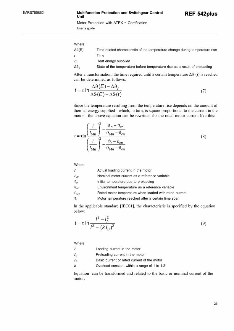
After a transformation, the time required until a certain temperature Δϑ (t) is reachedcan be determined as follows:
)()(
)(ln
tE
Et
p
��
���
���
���� (7)
Since the temperature resulting from the temperature rise depends on the amount ofthermal energy supplied - which, in turn, is square-proportional to the current in themotor - the above equation can be rewritten for the rated motor current like this:
t
ll
ll
p en
Mn en
t en
Mn en
=
⎛
⎝⎜
⎞
⎠⎟ −
−−
⎛
⎝⎜
⎞
⎠⎟ − −
−
τ
ϑ ϑϑ ϑ
ϑ ϑϑ ϑ
ln Mn
Mn
2
2 (8)
Where:
I Actual loading current in the motor
IMn Nominal motor current as a reference variable
ϑp Initial temperature due to preloading
ϑen Environment temperature as a reference variable
ϑMn Rated motor temperature when loaded with rated current
ϑt Motor temperature reached after a certain time span
In the applicable standard [IEC01], the characteristic is specified by the equationbelow:
22
22
)(ln
B
p
IkI
IIt
�
�� � (9)
Where:
I Loading current in the motor
Ip Preloading current in the motor
IB Basic current or rated current of the motor
k Overload constant within a range of 1 to 1.2
Equation can be transformed and related to the basic or nominal current of themotor:
Multifunction Protection and Switchgear ControlUnit
Motor Protection with ATEX − Certification
User´s guide
REF 542plusREF 542plus1MRS755862

2
2
B
2
B
2
Bln
kI
I
I
I
I
I
t
p
���
���
��
���
���
���
� � (10)
As a result, Equation (7) and Equation (10) indicate that the setting for constant
uMn
ut
����
��
�k (11)
can be derived from the setting for the temperatures. The temperature setting is ameasure for the thermal capacity. The denominator in the root equation above isequal to the nominal capacity contents under nominal operation condition of themotor. The numerator is identical to the extended thermal capacity of the motor fortripping and only allowed for a very short time duration.
3.4.1. Setting parameters
For operation purposes, the parameters need to be set as shown in the followingfigures.
A050528
Fig. 3.4.1.-1 Setting parameters for thermal protection
26
REF 542plusREF 542plus Multifunction Protection and Switchgear ControlUnit
Motor Protection with ATEX − Certification
User´s guide
1MRS755862

27
A050529
Fig. 3.4.1.-2 Setting parameters for thermal protection
Where:
TMn Nominal motor temperature (permissible operating temperature)
IMn Nominal motor current referred to the nominal current of the currenttransformer
Tini Initial temperature of the thermal memory after switching on the auxiliaryvoltage
TCOff Cooling-off time constant at I < 0.1 IMn (motor at standstill)
TCNormal Time constant at 0.1 IMn < I < 2 IMn (motor in normal operation)
TCOverheat Time constant at I > 2 IMn (motor during startup/accelerating)
Ttrip Temperature for tripping
Twarn Temperature for warning
Tenv Environment temperature
Trst Temperature after resetting the function
3.4.1.1. Setting the time constant
For setting the time constant, it is assumed that the motor is rotor-critical.Furthermore, it is assumed that the preset thermal capacity has been reached if, afterexpiration of the blocking time, the cold motor still remains rotor-locked. Therefore,Equation (10) delivers the following relationship:
τ =−
−
tI I
I I k
E
A Mn
A Mnln ( )
( )
2
2 21 (12)
Multifunction Protection and Switchgear ControlUnit
Motor Protection with ATEX − Certification
User´s guide
REF 542plusREF 542plus1MRS755862

Where:
τ Heating time constant to be calculated for rotor-critical motors andwhich can be equated to the setting for "TCOverheat“
tE Permissible maximum blocking time
IA Blocking current or maximum starting current
IMn Nominal motor current
k Overload constant which
According to the standard, the warm condition is defined if the motor reaches thesteady state condition during the operation with the nominal motor current. That iswhy the preload condition is equal to 1.
Thus, the value for TCOverheat (the time constant for motor operation at overloadabove 2 times the rated motor current) can be calculated on the basis of Equation .The temperature rise time constant TCNormal for non-rotor-critical motors could, inprinciple, be chosen larger than the above temperature rise time constant. If thisparameter is unknown, however, the same value can be set, as it is safe to expect atimely tripping in this case. As experience has shown, the cooling-off time constantwhile the motor is at zero rotation TCOff should be set within 3 times to 5 times thevalue of TCNormal.
3.4.1.2. Setting the temperature
For the setting of an ATEX certified motor, the thermal class is considered.According to [IEC02, IEC03], the thermal class for the motor is marked with therelated thermal class, listed in 3.4.1.2.-1.
Table 3.4.1.2.-1 Thermal class for ATEX certified motor
Thermal Class 105 (A) 120 (E) 130 (B) 155 (F) 180 (H)
Temperatureat nominalload in °C
95 110 120 130 166
Temperatureat the end oftime tE in °C
160 175 185 210 235
The letters in the bracket of the thermal class are the previous designation of thecorresponding temperature class. The values of the temperature at the nominal loadcondition and the end of time tE are taken from [IEC02].
Assuming that the motor in the example is marked with thermal class F and theenvironment temperature is 40°C, the motor can be overloaded with the followingconstant k according to the equation:
k = −−
=210 40130 40
1 37° °° °C CC C
. (13)
This means that the overload condition of the motor can be extended in comparisonto the previous example 1.
28
REF 542plusREF 542plus Multifunction Protection and Switchgear ControlUnit
Motor Protection with ATEX − Certification
User´s guide
1MRS755862
29
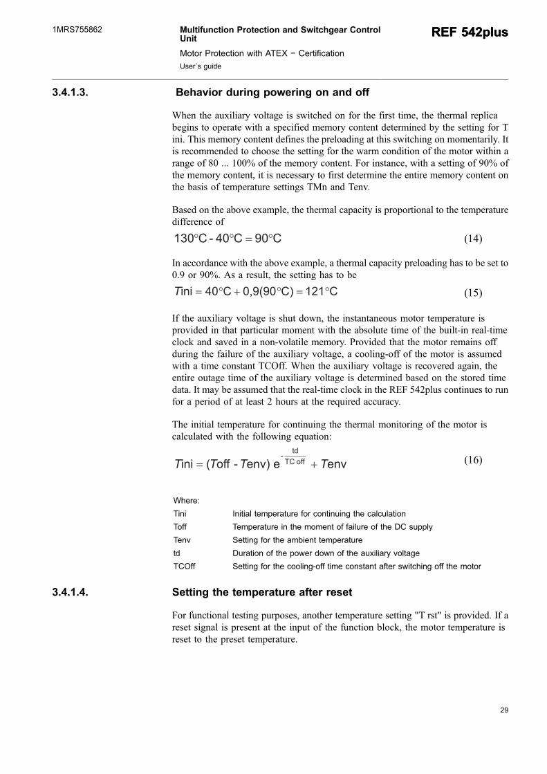
3.4.1.3. Behavior during powering on and off
When the auxiliary voltage is switched on for the first time, the thermal replicabegins to operate with a specified memory content determined by the setting for Tini. This memory content defines the preloading at this switching on momentarily. Itis recommended to choose the setting for the warm condition of the motor within arange of 80 ... 100% of the memory content. For instance, with a setting of 90% ofthe memory content, it is necessary to first determine the entire memory content onthe basis of temperature settings TMn and Tenv.
Based on the above example, the thermal capacity is proportional to the temperaturedifference of
C90C04-C130 ���� (14)
In accordance with the above example, a thermal capacity preloading has to be set to0.9 or 90%. As a result, the setting has to be
C121C)0,9(90C40ini ������T (15)
If the auxiliary voltage is shut down, the instantaneous motor temperature isprovided in that particular moment with the absolute time of the built-in real-timeclock and saved in a non-volatile memory. Provided that the motor remains offduring the failure of the auxiliary voltage, a cooling-off of the motor is assumedwith a time constant TCOff. When the auxiliary voltage is recovered again, theentire outage time of the auxiliary voltage is determined based on the stored timedata. It may be assumed that the real-time clock in the REF 542plus continues to runfor a period of at least 2 hours at the required accuracy.
The initial temperature for continuing the thermal monitoring of the motor iscalculated with the following equation:
enveenv)-off(ini offTC
td-
TTTT �� (16)
Where:
Tini Initial temperature for continuing the calculation
Toff Temperature in the moment of failure of the DC supply
Tenv Setting for the ambient temperature
td Duration of the power down of the auxiliary voltage
TCOff Setting for the cooling-off time constant after switching off the motor
3.4.1.4. Setting the temperature after reset
For functional testing purposes, another temperature setting "T rst" is provided. If areset signal is present at the input of the function block, the motor temperature isreset to the preset temperature.
Multifunction Protection and Switchgear ControlUnit
Motor Protection with ATEX − Certification
User´s guide
REF 542plusREF 542plus1MRS755862
For instance, if a tripping characteristic without preloading is to be checked,temperature setting T rst has to be equated to the setting of the environmenttemperature T env. For checking a characteristic with 100% preloading (hot curves),temperature setting T rst has to be set equal to the setting of the rated motortemperature T nom.
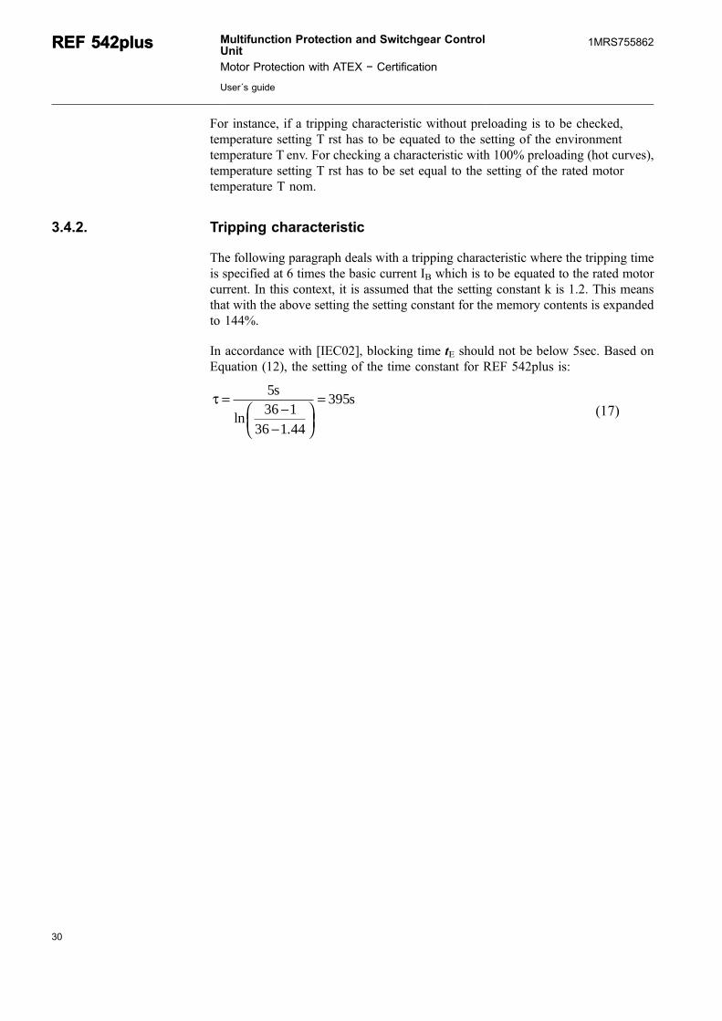
3.4.2. Tripping characteristic
The following paragraph deals with a tripping characteristic where the tripping timeis specified at 6 times the basic current IB which is to be equated to the rated motorcurrent. In this context, it is assumed that the setting constant k is 1.2. This meansthat with the above setting the setting constant for the memory contents is expandedto 144%.
In accordance with [IEC02], blocking time tE should not be below 5sec. Based onEquation (12), the setting of the time constant for REF 542plus is:
τ =−
−⎛⎝⎜
⎞⎠⎟
=536 1
36 1 44
395s
lns
.(17)
30
REF 542plusREF 542plus Multifunction Protection and Switchgear ControlUnit
Motor Protection with ATEX − Certification
User´s guide
1MRS755862
31
A050408
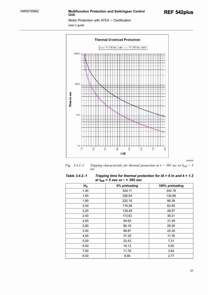
Fig. 3.4.2.-1 Tripping characteristic for thermal protection at τ = 395 sec or t6IB = 5sec
Table 3.4.2.-1 Tripping time for thermal protection for IA = 6 In and k = 1.2at tt6IB = 5 sec or τ = 395 sec
I/IB 0% preloading 100% preloading
1.40 524.11 242.18
1.60 326.54 130.89
1.80 232.18 86.38
2.00 176.28 62.65
2.20 139.49 48.07
2.40 113.63 38.31
2.60 94.62 31.39
2.80 80.16 26.26
3.00 68.87 22.35
4.00 37.25 11.76
5.00 23.43 7.31
6.00 16.12 5.00
7.00 11.78 3.64
8.00 8.99 2.77
Multifunction Protection and Switchgear ControlUnit
Motor Protection with ATEX − Certification
User´s guide
REF 542plusREF 542plus1MRS755862
3.4.3. Functional check
For functional testing, we recommend to use three-phase testing equipment. If afunctional test is to be carried out with single-phase testing equipment, attention isto be paid to the fact that the current has to be raised to achieve the same r.m.s. valueas with a three-phase system. For calculating the memory contents, the REF 542plusassumes that the root-mean-square value of the current in the individual phases ispresent.
3(3pol)
2L3
2L2
2L1
Mitte
IIII l
��� (18)
Where:
Imittel (3-pole) Root-mean-square value of the current causing the temperature rise in athree-pole functional test
IL1 Current in conductor L1
IL2 Current in conductor L2
IL3 Current in conductor L3
Therefore, in a single-phase test equipment, a temperature rise at a current of isassumed.
3(1pol)
2L1
Average
II � (19)
Where:
Iaverage (1-pole) Root-mean-square value of the current causing the temperature rise in asingle-pole functional test
IL1 Current in conductor L1,
Therefore in a single-phase test, the current
/( ) /( )1 3 3pol pol= (20)
shall be increased by factor √3 in order to obtain a temperature rise that iscomparable to the one in a three-pole functional test.
3.5. Unbalanced load protection
The unbalanced load protection is intended to provide protection and monitoring ofelectrical equipment against asymmetrical loading. Unbalanced load protection ismostly applied for protecting motors or generators.
The unbalanced load is calculated from the negative-phase-sequence component ofthe three-phase conductor currents and has to be generated — in accordance withthe definitions given in the applicable regulations — on the basis of the relationshipbetween the current of the negative-phase-sequence component and the rated current
32
REF 542plusREF 542plus Multifunction Protection and Switchgear ControlUnit
Motor Protection with ATEX − Certification
User´s guide
1MRS755862
33
of the equipment that is to be protected. Since an unbalanced load leads toimpermissible temperature rises in the laminated core of the rotor, it is necessary togenerate a tripping signal which is square-dependent on the unbalanced load in casethe permissible values are being exceeded. By means of the square-dependency, it ispossible to replicate a temperature rise without losses (adiabatic curves). Thetripping time can be derived as follows:
22
2 sII
Kt
�� (21)
Where:
t Tripping time derived from the above temperature rise constant
K Temperature rise constant depending on the type of equipment
I2 Unbalanced load related to the rated current
Is Response value for monitoring impermissible temperature rises
When a tripping took place, it is usually advisable not to restart the motorimmediately after the trip. The unbalanced load protection in the REF 542plus hastherefore been provided with the option to block motor reconnection by means of anoutput signal. Within the blocking time, the memory contents is subjected to linearclearing for the tripping time. If the component to be protected is reconnectedwithout waiting for a complete cool-off, it is possible that another trip will takeplace - if the unbalanced load limit is exceeded again - much faster than would beexpected theoretically. In addition, it is possible to reduce the duration of theblocking time, if necessary, in percentages.
3.5.1. Setting parameters
For operation purposes, the parameters need to be set as shown below:
Multifunction Protection and Switchgear ControlUnit
Motor Protection with ATEX − Certification
User´s guide
REF 542plusREF 542plus1MRS755862
A050414
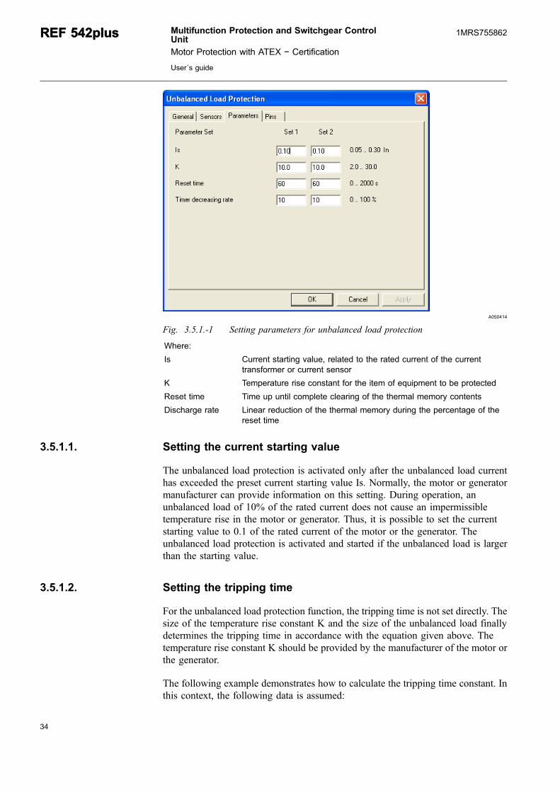
Fig. 3.5.1.-1 Setting parameters for unbalanced load protection
Where:
Is Current starting value, related to the rated current of the currenttransformer or current sensor
K Temperature rise constant for the item of equipment to be protected
Reset time Time up until complete clearing of the thermal memory contents
Discharge rate Linear reduction of the thermal memory during the percentage of thereset time
3.5.1.1. Setting the current starting value
The unbalanced load protection is activated only after the unbalanced load currenthas exceeded the preset current starting value Is. Normally, the motor or generatormanufacturer can provide information on this setting. During operation, anunbalanced load of 10% of the rated current does not cause an impermissibletemperature rise in the motor or generator. Thus, it is possible to set the currentstarting value to 0.1 of the rated current of the motor or the generator. Theunbalanced load protection is activated and started if the unbalanced load is largerthan the starting value.
3.5.1.2. Setting the tripping time
For the unbalanced load protection function, the tripping time is not set directly. Thesize of the temperature rise constant K and the size of the unbalanced load finallydetermines the tripping time in accordance with the equation given above. Thetemperature rise constant K should be provided by the manufacturer of the motor orthe generator.
The following example demonstrates how to calculate the tripping time constant. Inthis context, the following data is assumed:
34
REF 542plusREF 542plus Multifunction Protection and Switchgear ControlUnit
Motor Protection with ATEX − Certification
User´s guide
1MRS755862
35
K = 10
IMn = 80A (rated current of the motor)
In = 100A (rated current of the current transformer)
If an open-circuit condition is present, the currents in the other two conductors are ofequal size and have a phase displacement of 180°. Furthermore, it is assumed thatboth of the currents are identical with the rated current. Under this condition, theunbalanced load current I2 is:
I2 = 0.577 In
If this value is inserted into the equation above, the tripping time is 30.9s.
As the rated current of the current transformer is not identical to the rated motorcurrent — in this example the rated current of the current transformer is 100A andthe one of the motor is 80A — the setting of the temperature rise constant has to becorrected based on the relationship between the rated motor current and thetransformer rated current, as shown in the following equation:
���
�
���
��
��
��
��
�
2
Mn
2
MnAUS
n
s
nn
2
n I
I
I
I
I
I
I
ItK (22)
The constant which is to be set at the REF 542plus multifunctional control andprotection device for the above example is:
38,61,0100
80577,0
100
809,30
22
����
�
���
��
��
��
��
�K
(23)
3.5.2. Tripping characteristic
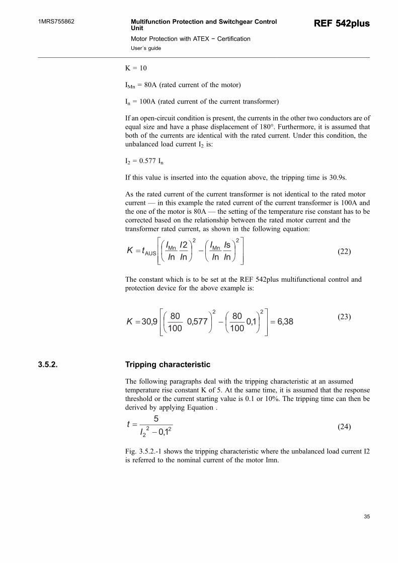
The following paragraphs deal with the tripping characteristic at an assumedtemperature rise constant K of 5. At the same time, it is assumed that the responsethreshold or the current starting value is 0.1 or 10%. The tripping time can then bederived by applying Equation .
22
2 1,0
5
��
It (24)
Fig. 3.5.2.-1 shows the tripping characteristic where the unbalanced load current I2is referred to the nominal current of the motor Imn.
Multifunction Protection and Switchgear ControlUnit
Motor Protection with ATEX − Certification
User´s guide
REF 542plusREF 542plus1MRS755862

A050418
Fig. 3.5.2.-1 Tripping characteristic for thermal protection at τ = 146sec or t6IB = 5sec
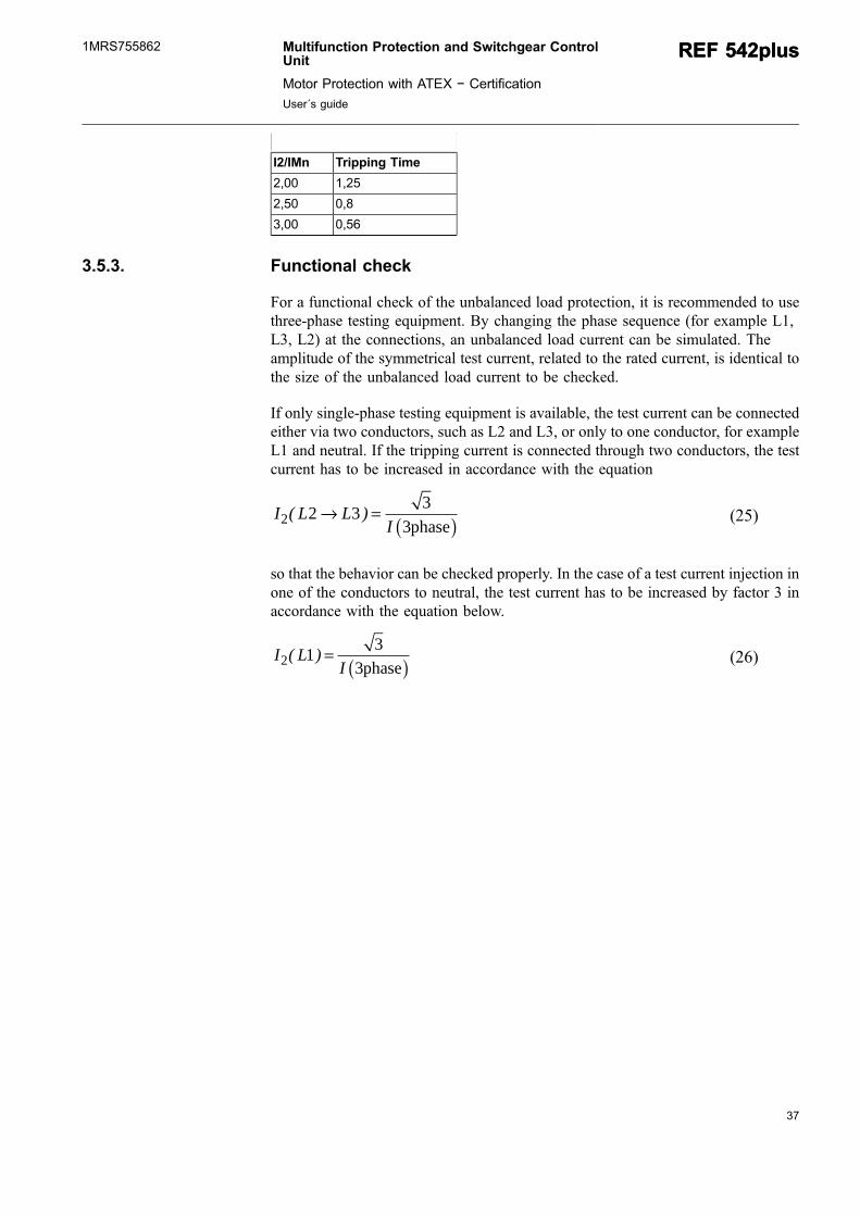
Table 3.5.2.-1 gives an overview of the times resulting for the trippingcharacteristic.
Table 3.5.2.-1 Tripping time for the unbalanced load protection
I2/IMn Tripping Time
0,20 166,67
0,30 62,5
0,40 33,33
0,50 20,83
0,60 14,23
0,70 10,42
0,80 7,94
0,90 6,25
1,00 4,95
1,20 3,5
1,30 2,98
1,40 2,56
1,50 2,23
36
REF 542plusREF 542plus Multifunction Protection and Switchgear ControlUnit
Motor Protection with ATEX − Certification
User´s guide
1MRS755862
37
I2/IMn Tripping Time
2,00 1,25
2,50 0,8
3,00 0,56
3.5.3. Functional check
For a functional check of the unbalanced load protection, it is recommended to usethree-phase testing equipment. By changing the phase sequence (for example L1,L3, L2) at the connections, an unbalanced load current can be simulated. Theamplitude of the symmetrical test current, related to the rated current, is identical tothe size of the unbalanced load current to be checked.
If only single-phase testing equipment is available, the test current can be connectedeither via two conductors, such as L2 and L3, or only to one conductor, for exampleL1 and neutral. If the tripping current is connected through two conductors, the testcurrent has to be increased in accordance with the equation
I L LI2 2 3 3
3( )→ = ( )phase (25)
so that the behavior can be checked properly. In the case of a test current injection inone of the conductors to neutral, the test current has to be increased by factor 3 inaccordance with the equation below.
I LI2 1 3
3( ) = ( )phase (26)
Multifunction Protection and Switchgear ControlUnit
Motor Protection with ATEX − Certification
User´s guide
REF 542plusREF 542plus1MRS755862

38

39
4. Setting exampleThe following paragraph presents an example for setting the motor protectionfunctions which are used for thermal supervision. Special consideration is given tothe setting of the following functions:
* Rotor block protection* Motor start protection* Thermal overload protection* Number of starts protection
The setting of the unbalanced load protection function, which is needed for thesupervision of the asymmetrical operating conditions, has been described in theprevious paragraph.
In the following figure an example of the FUPLA − configuration of the functionblocks for motor protection - Block Rotor, Motor Start, Number of Start Supervisionand Thermal overload - are shown.
A050421
Fig. 4.-1 Example of a FUPLA − configuration for the motor protection
For the setting example, a medium voltage motor is assumed to have the followingrelevant data:
Multifunction Protection and Switchgear ControlUnit
Motor Protection with ATEX − Certification
User´s guide
REF 542plusREF 542plus1MRS755862
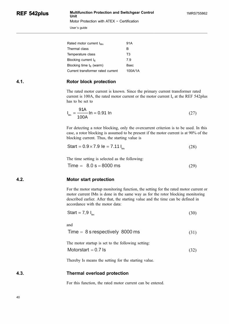
Rated motor current IMn 91A
Thermal class B
Temperature class T3
Blocking current IE 7.9
Blocking time tE (warm) 8sec
Current transformer rated current 100A/1A
4.1. Rotor block protection
The rated motor current is known. Since the primary current transformer ratedcurrent is 100A, the rated motor current or the motor current Ie at the REF 542plushas to be set to
IA
100AIn 0.91 InMn = =
91(27)
For detecting a rotor blocking, only the overcurrent criterion is to be used. In thiscase, a rotor blocking is assumed to be present if the motor current is at 90% of theblocking current. Thus, the starting value is
Start Ie IMn= × =0 9 7 9 7 11. . . (28)
The time setting is selected as the following:
ms8000s8.0Time �� (29)
4.2. Motor start protection
For the motor startup monitoring function, the setting for the rated motor current ormotor current IMn is done in the same way as for the rotor blocking monitoringdescribed earlier. After that, the starting value and the time can be defined inaccordance with the motor data:
Start IMn= 7 9, (30)
and
ms8000lyrespectives8Time � (31)
The motor startup is set to the following setting:
Is0.7Motorstart � (32)
Thereby Is means the setting for the starting value.
4.3. Thermal overload protection
For this function, the rated motor current can be entered.
40
REF 542plusREF 542plus Multifunction Protection and Switchgear ControlUnit
Motor Protection with ATEX − Certification
User´s guide
1MRS755862
41
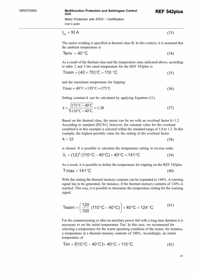
I AMn = 91 (33)
The motor winding is specified at thermal class B. In this context, it is assumed thatthe ambient temperature is
C40Tenv �� (34)
As a result of the thermal class and the temperature class indicated above, accordingto table 2 and 3 the rated temperature for the REF 542plus is
C110)7040(Tnom ����� C (35)
and the maximum temperature for tripping:
Tmax C C C= + =40 135 175° ° ° (36)
Setting constant k can be calculated by applying Equation (11).
k = −−
=175 40110 40
1 38° °° °C CC C
. (37)
Based on the thermal class, the motor can be set with an overload factor k>1.2.According to standard [IEC01], however, the constant value for the overloadcondition k in this example is selected within the standard range of 1.0 to 1.2. In thisexample, the highest possible value for the setting of the overload factor
2,1k � (38)
is chosen. It is possible to calculate the temperature setting in reverse order.
C141C40C)40C110()2,1( 2t ��������� (39)
As a result, it is possible to define the temperature for tripping on the REF 542plus
C141maxT �� (40)
With this setting the thermal memory contents can be expanded to 144%. Awarningsignal has to be generated, for instance, if the thermal memory contents of 120% isreached. This way, it is possible to determine the temperature setting for the warningsignal.
C124C40C)40C110(100
120Twarn �����
��
����
(41)
For the commissioning or after an auxiliary power fail with a long time duration it isnecessary to set the initial temperature Tini. In this case, we recommend forselecting a temperature for the warm operating condition of the motor, for instance,a temperature at a thermal memory contents of 100%. Accordingly, an initialtemperature of
� � C110C40C40C110Tini �������� (42)
Multifunction Protection and Switchgear ControlUnit
Motor Protection with ATEX − Certification
User´s guide
REF 542plusREF 542plus1MRS755862

is assumed.
Since the motor has to be assumed as being rotor-critical without forced cooling,both of the time constants as well as for the temperature rise in operating conditionas also for the overload or fault condition should be identical. The time constant canbe calculated by applying Equation (12).
s1112
2,19,7
19,7ln
s0,8
22
2�
�
���
(43)
As a result, the two time constants should be set as follows:
s1112OverheatTCNormalTC �� (44)
If the motor is no longer running and is not rotating, cooling-off takes place slowlyas there is no more rotation. Generally, the cooling-off process can be assumed witha time constant that is three times the value for normal operation. Therefore the timeconstant for cooling-off at standstill is set as follows:
s3336s21113TCoff �� (45)
If the overload factor k=1.38 according to the thermal class is to beused, the calculation can be done similarly.
4.4. Number of starts protection
In accordance with the recommendations given in the relevant operation guidelines,the setting of the number of starts from cold condition is
2ColdstartofNumber � (46)
and the setting of the number of starts from warm condition is
1WarmstartofNumber � (47)
According to the selected setting, after each start the thermal memory will be filledup by 45%. After 2 start the thermal memory will reach 90% of the nominal value.So the temperature for the warm start is reached if the thermal memory content is100%. This way, it is possible to define the temperature for the warm start.
C141C40C)40C141(100
100Tini �����
��
���� (48)
42
REF 542plusREF 542plus Multifunction Protection and Switchgear ControlUnit
Motor Protection with ATEX − Certification
User´s guide
1MRS755862

43
The time for motor cool-off can be assumed to be 0.6 of the setting of the timeconstant TCOff. After expiration of this time the thermal memory is reduced byapproximately 45%. A warm start can at least be performed.
s200133366.0Time �� (49)
4.5. Tripping characteristic
The figure below shows the tripping characteristic of the motor in cold condition.
A050450
Fig. 4.5.-1 Tripping characteristic from a combination of the protection functions
The tripping characteristic is formed from a combination of the motor protectionfunctions. Within a 1.2 to 4.7 basic current or rated motor current IB, a tripping iseffected by the thermal protection function; within a range of 4.7 ... 6.3 basic currentor rated motor current IB, a tripping is effected by the motor startup monitoringfunction. In the range above 6.3 IB, a tripping is effected by the rotor monitoringfunction. The higher the temperature rise or the thermal memory contents, theshorter the tripping time of the thermal protection function. The illustration belowshows how the tripping time changes in comparison with the one applicable to thecold condition.
Multifunction Protection and Switchgear ControlUnit
Motor Protection with ATEX − Certification
User´s guide
REF 542plusREF 542plus1MRS755862

A050451
Fig. 4.5.-2 Reducing the tripping time at a 100% preloading
4.6. Behavior after recovering of the auxiliary voltage
When the auxiliary voltage of the REF 542plus fails, the motor to be protected mustalso be switched off. The duration of the failure of the auxiliary voltage can besupervised by the internal real time clock. The clock is able to operate in the next 2hours with the required accuracy. As soon as the auxiliary voltage recovers again,the cooled down motor temperature is calculated according to Equation (16). Theresult of the calculated temperature is now used as initial temperature to continue thethermal overload protection of the motor.
In this example the following are assumed:
td = 10 Min = 600 s
Tfail = 130°C
Tenviro = 20°C
Zk off = 1026 s
After recovering of the auxiliary voltage the following temperature will be used forcontinuing the operation of the motor protection:
44
REF 542plusREF 542plus Multifunction Protection and Switchgear ControlUnit
Motor Protection with ATEX − Certification
User´s guide
1MRS755862
45
CCT ������
���
�
�� 9640e40)-141(ini 1026s
600s- (50)
Where:
td Duration of the failure of the auxiliary voltage
Tfail Temperature at the moment failure occurrence
Tenviro Setting of the environmental temperature
TimeConst I < 0.1 Ie Setting of the time constant for cooling down the motor at standstill
Tini Initial temperature for the continuation of the protection task
Multifunction Protection and Switchgear ControlUnit
Motor Protection with ATEX − Certification
User´s guide
REF 542plusREF 542plus1MRS755862

46

47
5. Operation of the REF 542plusIn this chapter, you will find the following information:
Operator’s responsibilities
Guarantee provisions
General safety notes
Special safety warnings that must always be observed when working with theREF 542plus.
5.1. Operator's responsibilities
Please observe the following information for the operator:
The operating personnel for the REF 542plus must have the appropriatequalifications for working on the unit.
Your operating personnel must be authorized to work with or on REF 542plus, forexample, switching authorization in substations.
Changes to the application as delivered may be made only by the ABB personnel
For the guarantee reasons, changes to the application as delivered made by thecustomer must always be approved by the appropriate ABB sales department.
We recommend that only the ABB personnel make adjustments to the unit. Once theguarantee has expired, the unit is opened at your own risk and is permitted afterconsultation with the ABB office that sold the unit.
5.2. Guarantee Provisions
The data provided in this documentation is intended solely to describe the productand must not be considered as assured properties. In the interest of users, we arecontinually striving to bring our products up to the latest state of the art intechnology. For this reason there may be differences between the product, theproduct description and the manual.
If the instructions and recommendations of our documentation are observed, then,according to our experience, the best possible operational reliability of our productsis guaranteed.
It is virtually impossible for comprehensive documentation to cover every possibleevent that may possibly occur when using technical devices and apparatus. Wetherefore request that our representatives or we are consulted in the event of anyunusual incidents and in cases for which this Manual does not providecomprehensive information.
Multifunction Protection and Switchgear ControlUnit
Motor Protection with ATEX − Certification
User´s guide
REF 542plusREF 542plus1MRS755862
We explicitly refuse to accept any responsibility for all direct damages that occur asa result of erroneous usage of our devices, even if no special instructions on this areincluded in the manual.
The documentation has been carefully checked. If the user should find any defectsin spite of this, we request that you inform us as quickly as possible.
Special arrangements may be made in agreement with the users and will bespecified in the contract documentation.
In general, all agreements, assurances, legal relationships and all the ABBobligations arise from the current valid contract documentation, including anyreference to the warranty provisions, which are not influenced by the content of thisdocumentation.
ABB assumes no responsibility for damages resulting from improper use ofREF 542plus.
In the event of a guarantee claim, please contact the ABB office that sold the unit.
5.3. Safety Regulations
The safety notes in the following chapters represent only a general selection of thepoints that must be observed. Additional safety notes applicable to the actual contentof the chapter can be found in the other specific parts of the manual.
Safety notes are either at the beginning of the section or directly at the relevantposition in the text.
5.3.1. General safety notes
Documentation
The content of the documentation supplied with the device must befollowed in all circumstances when the device is in operation.
Operating an electrical device
When any electrical device is being operated, specific parts of thedevice are subject to voltage. If safety warnings are not followed,hazards to personnel and property will result. Personal injury anddamage to property may also occur.
48
REF 542plusREF 542plus Multifunction Protection and Switchgear ControlUnit
Motor Protection with ATEX − Certification
User´s guide
1MRS755862
49
Safe Operation
The device must be properly transported and stored to ensure fault-freeand safe operation. In addition, commissioning, control, service andmaintenance must be properly and thoroughly conducted.
5.3.2. Specific safety information
The following five safety rules according to the so called "VBG4 ElectricalSubstations and Equipment“ must be observed in all circumstances for personalsafety:
Isolate the system before beginning the work.
Secure against the reactivation.
Ensure that there is no voltage.
Ground and short circuit.
Cover or shut out neighboring parts under power.
The following safety standards must be observed in all circumstances:IEC 60255 for protection relays in high-voltage substations and DIN57627 plug connections.
Working on and operating the device:
Only qualified personnel may work on and operate the device.
Qualified personnel are:
Entrusted with the setup, installation, commissioning and operation of the deviceand the system in which it is installed.
Multifunction Protection and Switchgear ControlUnit
Motor Protection with ATEX − Certification
User´s guide
REF 542plusREF 542plus1MRS755862
Qualified and authorized to conduct switching operations in accordance with thestandards of safety engineering. This specifically includes switching on and off,isolating, grounding and signage.
Trained in safety engineering standards and are familiar with the maintenance andthe use of safety equipment.
Trained in first aid.
5.3.3. Risk analysis and safety measures
The risk analysis and the safety measures are mentioned in [DO1]. It can beconcluded, that the motor protection function in the REF 542plus can fulfil therequirement class 3 of DIN V 19250. By means of the watch-dog function allemergency situation can be detected in order to switch off the protected motor.Consequently disturbances with possibly environment pollution can be avoid, evenif the process is unmanned.
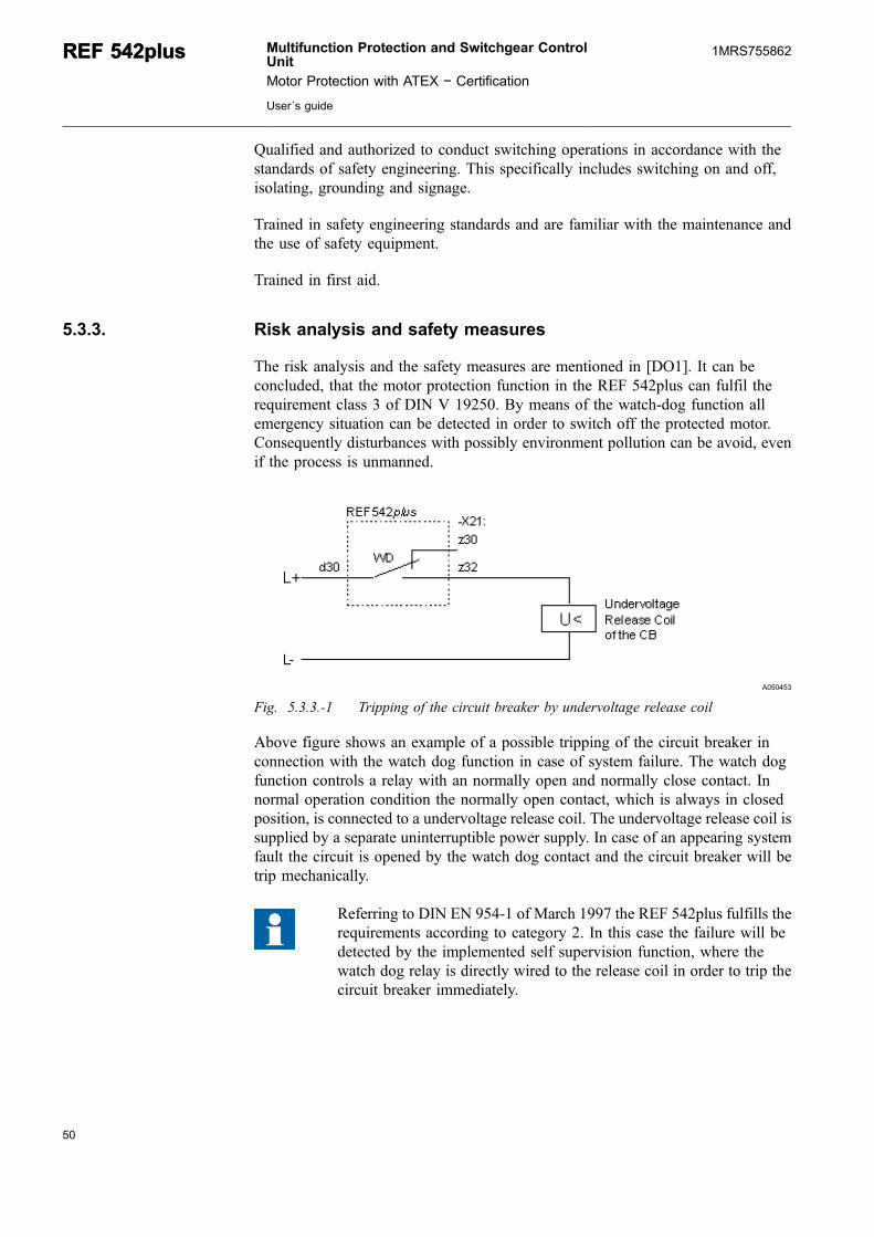
A050453
Fig. 5.3.3.-1 Tripping of the circuit breaker by undervoltage release coil
Above figure shows an example of a possible tripping of the circuit breaker inconnection with the watch dog function in case of system failure. The watch dogfunction controls a relay with an normally open and normally close contact. Innormal operation condition the normally open contact, which is always in closedposition, is connected to a undervoltage release coil. The undervoltage release coil issupplied by a separate uninterruptible power supply. In case of an appearing systemfault the circuit is opened by the watch dog contact and the circuit breaker will betrip mechanically.
Referring to DIN EN 954-1 of March 1997 the REF 542plus fulfills therequirements according to category 2. In this case the failure will bedetected by the implemented self supervision function, where thewatch dog relay is directly wired to the release coil in order to trip thecircuit breaker immediately.
50
REF 542plusREF 542plus Multifunction Protection and Switchgear ControlUnit
Motor Protection with ATEX − Certification
User´s guide
1MRS755862

51
6. Mounting and InstallationIn this chapter, you will find information on:
* What to do first the REF 542plus is delivered* Requirements for the installation location and the environmental conditions* How to set up REF 542plus and integrate it into the switchgear* How to check the wiring to run the commissioning process
6.1. Unpacking
The REF 542plus multifunctional control and protection unit does not requirespecial shipping protection. The packaging is adapted for the shipping type anddestination. Proceed with the unpacking as follows:
1. Visually inspect the unit and the packaging when unpacking it. Any shippingdamage found in the packaging or the unit should be reported immediately to thelast shipper, who should be informed in writing of liability for the damage.
2. Check the delivery for completeness by using the order documentation. If thereis anything missing or any discrepancies with the order documentation, contactthe ABB sales office immediately.
3. Mount the unit as described in the following section. If the unit is not forimmediate use, store it in a suitable place in its original packaging.
6.2. Mounting
REF 542plus consists of two parts, a Base Unit and a separate Human MachineInterface (HMI) as the Control Unit. The Base Unit contains the power supply,mainboard and analog inputs and binary Input and Output (I/O) modules, as well asoptional modules for the supplementary functions. The HMI Control Unit is a stand-alone unit with its own power supply. It can be installed on the Low Voltage (LV)compartment door or in a dedicated compartment close to the Base Unit. The HMIis used to set the protection parameters and to locally operate the switching devicesin the switchbay. An isolated and shielded twisted pair according to the RS485standard interface shall be used for the connection of the HMI as the Control unit tothe Central Unit.
The following figures show the dimensions of the HMI Control Unit and CentralUnit.
Multifunction Protection and Switchgear ControlUnit
Motor Protection with ATEX − Certification
User´s guide
REF 542plusREF 542plus1MRS755862
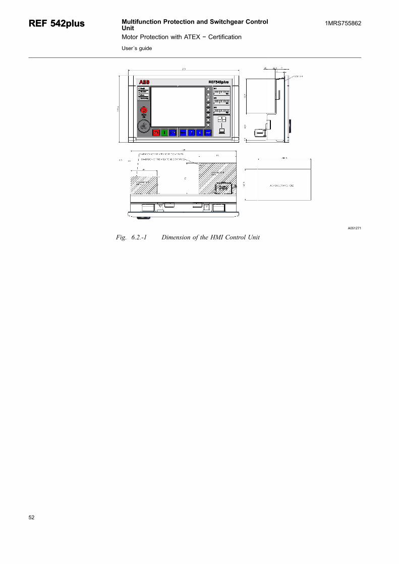
A051271
Fig. 6.2.-1 Dimension of the HMI Control Unit
52
REF 542plusREF 542plus Multifunction Protection and Switchgear ControlUnit
Motor Protection with ATEX − Certification
User´s guide
1MRS755862

53
10 233,5 18
M4
75
,57
5,5
ca. 70 261,5
M4
10
6,3
140 1233
185
10
6,3
24
4,8
10 18233,5
M4
75
,57
5,5
�0,1
�0,1
�0
,1�
0,1
�0
,1�
0,1
�0
,1�
0,1
� 0,1
A051268
Fig. 6.2.-2 Dimension of the Base Unit housing, standard version
Multifunction Protection and Switchgear ControlUnit
Motor Protection with ATEX − Certification
User´s guide
REF 542plusREF 542plus1MRS755862
10 233,5 18
M4
97,5
97,5
M4
106,3
184 1233
229
106,3
244,8
ca. 70 261,5
97,5
97,5
10 233,5 18
M4
� 0,1
�0,1
� 0,1
�0,1
�0,1
�0,1
�0,1
�0,1
�0,1
A051269
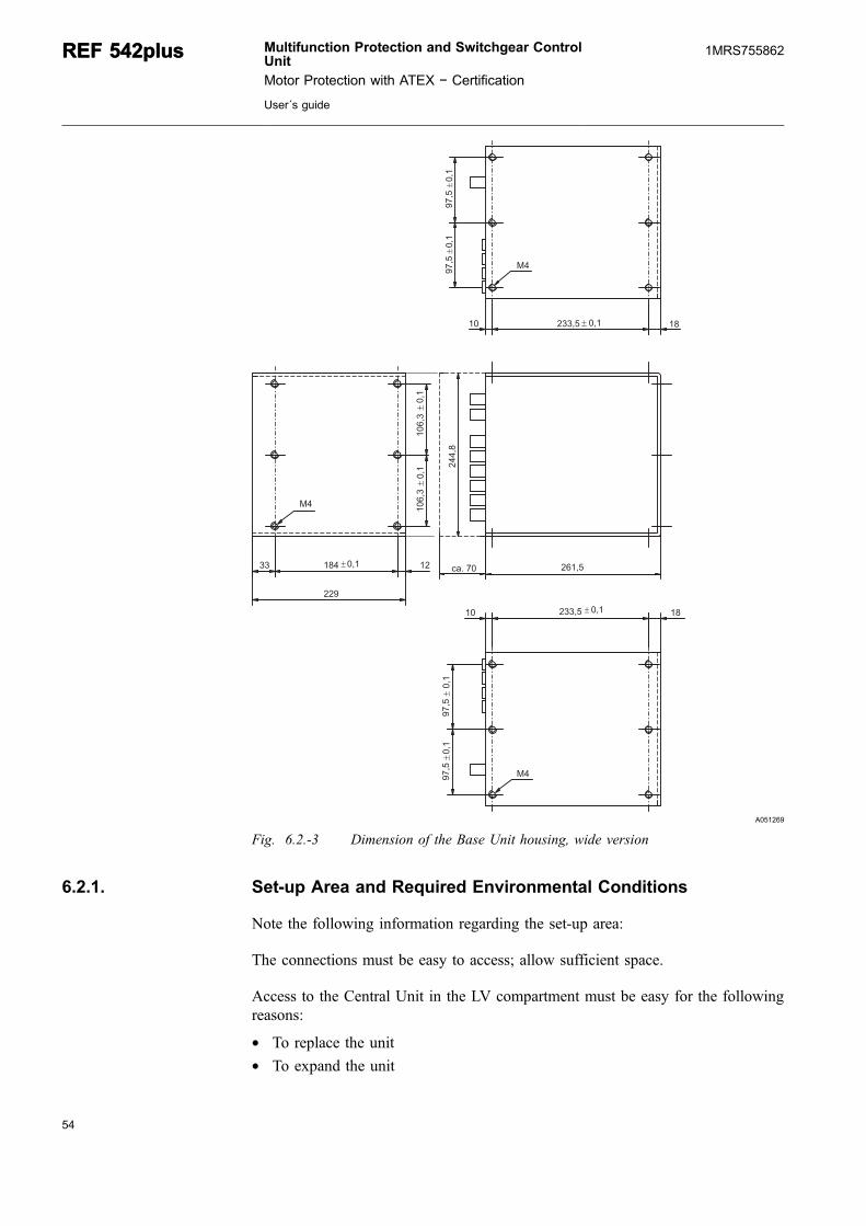
Fig. 6.2.-3 Dimension of the Base Unit housing, wide version
6.2.1. Set-up Area and Required Environmental Conditions
Note the following information regarding the set-up area:
The connections must be easy to access; allow sufficient space.
Access to the Central Unit in the LV compartment must be easy for the followingreasons:
* To replace the unit* To expand the unit
54
REF 542plusREF 542plus Multifunction Protection and Switchgear ControlUnit
Motor Protection with ATEX − Certification
User´s guide
1MRS755862

55
* To replace specific electronic equipment boards* To replace specific modules if necessary
Because the unit is sensitive to non-permitted severe environmental conditions,observe the following:
* The set-up area must be free of excessive air contamination (dust, aggressivesubstances).
* The natural air circulation around the unit must be free.* The set-up area must maintain the specified environmental conditions.
6.2.2. Installation in LV panels
A050395
Fig. 6.2.2.-1 REF 542plus installed in gas-insulated switchgears (GIS)
Multifunction Protection and Switchgear ControlUnit
Motor Protection with ATEX − Certification
User´s guide
REF 542plusREF 542plus1MRS755862
A070118
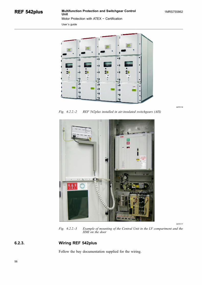
Fig. 6.2.2.-2 REF 542plus installed in air-insulated switchgears (AIS)
A070117
Fig. 6.2.2.-3 Example of mounting of the Central Unit in the LV compartment and theHMI on the door
6.2.3. Wiring REF 542plus
Follow the bay documentation supplied for the wiring.
56
REF 542plusREF 542plus Multifunction Protection and Switchgear ControlUnit
Motor Protection with ATEX − Certification
User´s guide
1MRS755862
57
In conclusion, the checks described in the following paragraphs can be done toensure that the wiring is correctly installed.
6.2.3.1. Checking the current transformer circuits
To check that the current transformer and the current transformer circuits are wiredcorrectly, run the following checks:
1. Polarity check The polarity check (as close as possible to REF 542plus) is usedto check the current circuit and also the installation position and the polarity ofthe transducer. The polarity of the transducers to one another can also be checkedwith load current.
2. Current feed with heavy current source (primary test instrument) providesinformation on the transducer transformation and the correct wiring toREF 542plus. The power supply should be per conductor and run fromconductor to conductor in each case. All the line currents and the residual currentshould be checked here. The transducer transformation can also be checked withload current.
3. Recording the magnetizing characteristic ensures that REF 542plus is connectedto a protective core and not to a measuring core.
4. Checking the transducer circuit ground at every independent current circuit maybe grounded at only one point to prevent balancing currents resulting frompotential differences.
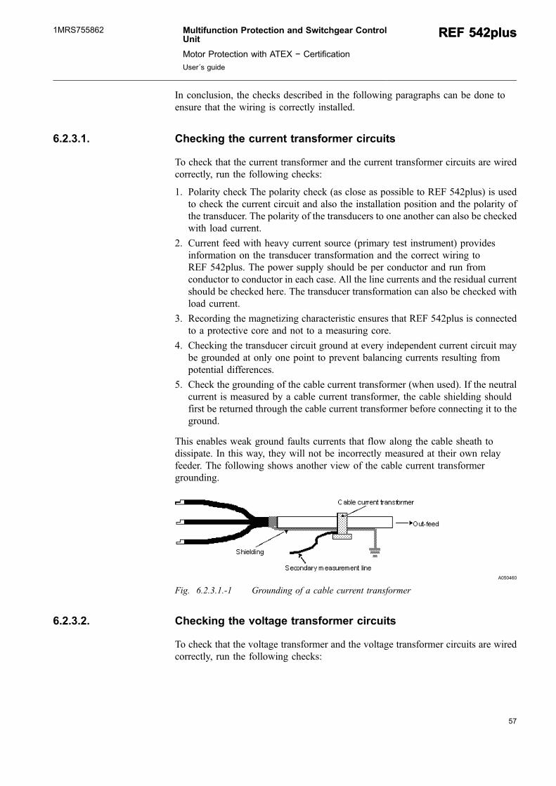
5. Check the grounding of the cable current transformer (when used). If the neutralcurrent is measured by a cable current transformer, the cable shielding shouldfirst be returned through the cable current transformer before connecting it to theground.
This enables weak ground faults currents that flow along the cable sheath todissipate. In this way, they will not be incorrectly measured at their own relayfeeder. The following shows another view of the cable current transformergrounding.
A050460
Fig. 6.2.3.1.-1 Grounding of a cable current transformer
6.2.3.2. Checking the voltage transformer circuits
To check that the voltage transformer and the voltage transformer circuits are wiredcorrectly, run the following checks:
Multifunction Protection and Switchgear ControlUnit
Motor Protection with ATEX − Certification
User´s guide
REF 542plusREF 542plus1MRS755862

1. Polarity check
2. Wiring check
3. Check the transformer circuit grounding
Check the voltage transformer for neutral point-ground voltage (when used). Tomeasure the ground faults, proceed as follows: The voltage is referred to as neutralpoint-ground voltage of a ground fault measurement, when it occurs with a metallicground fault in the network between terminals "e“ and "n“ of the open deltawinding. In the event of a metallic ground fault in phase L1, the external phase-to-neutral voltages occur in phases L2 and L3 instead of the conductor-groundvoltages. They are added geometrically and yield three times the amplitude betweenterminals "e“ and "n“.
6.2.3.3. Checking the auxiliary voltage
The auxiliary voltage must be in the tolerance range of power supply module andhave the proper polarity under all operating conditions.
6.2.3.4. Checking the tripping and signaling contacts
Conduct this check as shown in the bay documentation.
6.2.3.5. Checking the binary inputs
Check the polarity and the voltage value of the binary inputs on REF 542plus inaccordance with the technical data of the binary inputs.
6.2.4. Grounding of REF 542plus
To ensure EMC (Electro Magnetic Compatibility) the housing must be connected bya low transfer impedance to the grounding system. To achieve this condition thehousing of the base unit shall be screwed directly with the metallic plate, which shallbe a part of the low voltage compartment within the panel of the switchgear.Because of the relatively big surface area of the housing of the REF 542plus baseunit, the transfer impedance to the grounding system of the panel will be very low.In Fig. 6.2.4.-1 is an example of the installation can be seen.
58
REF 542plusREF 542plus Multifunction Protection and Switchgear ControlUnit
Motor Protection with ATEX − Certification
User´s guide
1MRS755862

59
A051270
Fig. 6.2.4.-1 Grounding of the REF 542plus base unit housing
6.2.5. Typical examples of analog and binary connections
The following pages show examples for wiring analog inputs (measuring inputs) onREF 542plus with sensors or transducers, binary I/Os and analog output boards.Typical examples of usage in practice are shown here. The following symbols areused in the circuit diagrams:
Table 6.2.5.-1 Graphical symbols for electric diagram (IEC 60617)
Symbol Legend Symbol Legend
Energy flow from the busbar
Ring core currenttransformer
Energy flow towards thebus bar
Make contact
Mechanical, pneumatic orhydraulic connection (link)
Break contact
Earth, ground Change-over break beforemake contact
Conductors in a screenedcable
Position switch, breakcontact
Twisted conductors Circuit breaker
Connection of conductors Disconnector
Multifunction Protection and Switchgear ControlUnit
Motor Protection with ATEX − Certification
User´s guide
REF 542plusREF 542plus1MRS755862

Symbol Legend Symbol Legend
Plug and socket male andfemale)
Operating device
Resistor with one fixedtapping
Fuse
Current transformer Sensing element
Three-phase transformer Current sensing element
Voltage transformer Optical fibre cable
6.2.6. Connection example of the REF 542plus analog inputs
A050487
Fig. 6.2.6.-1 Example of connection diagram for incoming or outgoing bays withtransformers
60
REF 542plusREF 542plus Multifunction Protection and Switchgear ControlUnit
Motor Protection with ATEX − Certification
User´s guide
1MRS755862

61
A050488
Fig. 6.2.6.-2 Example of connection diagram for incoming or outgoing bays withsensors
Due to accuracy requirements the length of the cable connection to thesensors in other bay respectively panels should be less than 7 m
Multifunction Protection and Switchgear ControlUnit
Motor Protection with ATEX − Certification
User´s guide
REF 542plusREF 542plus1MRS755862

62

63
7. CommissioningThe following sections with their subsections contain information on:
* The devices and facilities required for the commissioning inspection.* The required procedure for the commissioning inspection, for example,
depending on the components to be tested: protection, interlock conditions,communications, measured value recording and determining the direction.
7.1. Safety Information
The devices, adapters and procedures described are only examples. Experience andsafety in handling the various devices is a requirement.
7.2. Switching on the feeder
Before switching on the feeder, check that REF 542plus is fullyfunctional in the corresponding bay. Pay particular attention to theprotective functions and the interlocking.
7.3. Test equipment
The most important device for the commissioning of REF 542plus is an appropriateprotection test equipment. The test equipment should have a three-phase current andvoltage system. Also, the simulation of the Rogowski coil as current sensors andohmic divider as voltage sensors by the test equipment is possible. A test equipmentmanufactured by KOCOS in Korbach/Germany can be used, for example.
7.4. Testing the interlock conditions
This test is intended to check the interlocking of the switchgear that the user wantsand is required. The two types of interlocking must be taken into account here:
1. Bay-level interlocking of specific switchgear
2. Station-level interlocking of the bay versus other bays
The interlock conditions for the bay under test can be found in the orderdocumentation. The interlock conditions specified by the user can be found there.
All possible circumstances must be checked.
7.5. Determining the transformer direction
The connection of the measuring inputs and the correct polarity of the current andvoltage transformers or sensors is very important for directional functions.
Multifunction Protection and Switchgear ControlUnit
Motor Protection with ATEX − Certification
User´s guide
REF 542plusREF 542plus1MRS755862
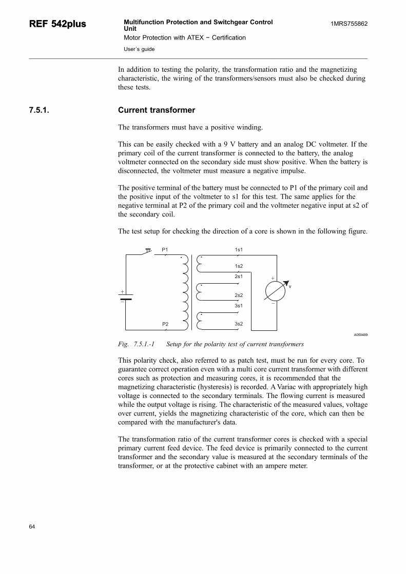
In addition to testing the polarity, the transformation ratio and the magnetizingcharacteristic, the wiring of the transformers/sensors must also be checked duringthese tests.
7.5.1. Current transformer
The transformers must have a positive winding.
This can be easily checked with a 9 V battery and an analog DC voltmeter. If theprimary coil of the current transformer is connected to the battery, the analogvoltmeter connected on the secondary side must show positive. When the battery isdisconnected, the voltmeter must measure a negative impulse.
The positive terminal of the battery must be connected to P1 of the primary coil andthe positive input of the voltmeter to s1 for this test. The same applies for thenegative terminal at P2 of the primary coil and the voltmeter negative input at s2 ofthe secondary coil.
The test setup for checking the direction of a core is shown in the following figure.
��
�� ���
�
���
���
���
���
���
A050489
Fig. 7.5.1.-1 Setup for the polarity test of current transformers
This polarity check, also referred to as patch test, must be run for every core. Toguarantee correct operation even with a multi core current transformer with differentcores such as protection and measuring cores, it is recommended that themagnetizing characteristic (hysteresis) is recorded. AVariac with appropriately highvoltage is connected to the secondary terminals. The flowing current is measuredwhile the output voltage is rising. The characteristic of the measured values, voltageover current, yields the magnetizing characteristic of the core, which can then becompared with the manufacturer's data.
The transformation ratio of the current transformer cores is checked with a specialprimary current feed device. The feed device is primarily connected to the currenttransformer and the secondary value is measured at the secondary terminals of thetransformer, or at the protective cabinet with an ampere meter.
64
REF 542plusREF 542plus Multifunction Protection and Switchgear ControlUnit
Motor Protection with ATEX − Certification
User´s guide
1MRS755862
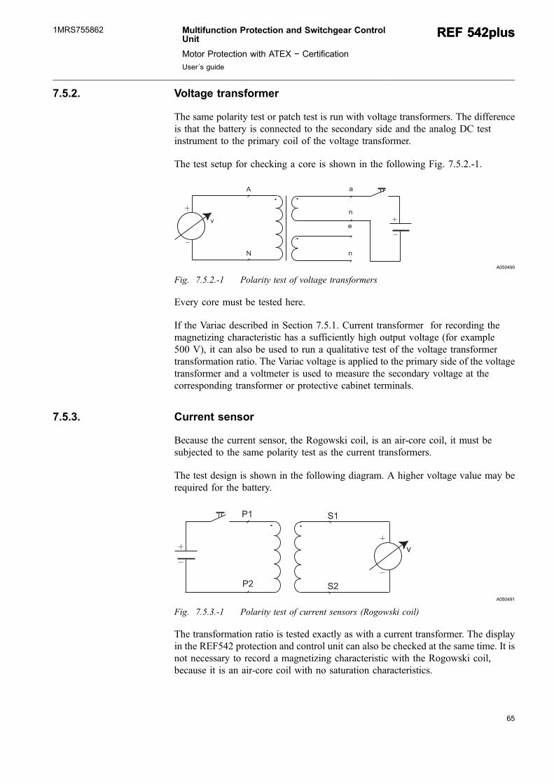
65
7.5.2. Voltage transformer
The same polarity test or patch test is run with voltage transformers. The differenceis that the battery is connected to the secondary side and the analog DC testinstrument to the primary coil of the voltage transformer.
The test setup for checking a core is shown in the following Fig. 7.5.2.-1.
�
�
�
�
A050490
Fig. 7.5.2.-1 Polarity test of voltage transformers
Every core must be tested here.
If the Variac described in Section 7.5.1. Current transformer for recording themagnetizing characteristic has a sufficiently high output voltage (for example500 V), it can also be used to run a qualitative test of the voltage transformertransformation ratio. The Variac voltage is applied to the primary side of the voltagetransformer and a voltmeter is used to measure the secondary voltage at thecorresponding transformer or protective cabinet terminals.
7.5.3. Current sensor
Because the current sensor, the Rogowski coil, is an air-core coil, it must besubjected to the same polarity test as the current transformers.
The test design is shown in the following diagram. A higher voltage value may berequired for the battery.
�
��
��
��
��
A050491
Fig. 7.5.3.-1 Polarity test of current sensors (Rogowski coil)
The transformation ratio is tested exactly as with a current transformer. The displayin the REF542 protection and control unit can also be checked at the same time. It isnot necessary to record a magnetizing characteristic with the Rogowski coil,because it is an air-core coil with no saturation characteristics.
Multifunction Protection and Switchgear ControlUnit
Motor Protection with ATEX − Certification
User´s guide
REF 542plusREF 542plus1MRS755862
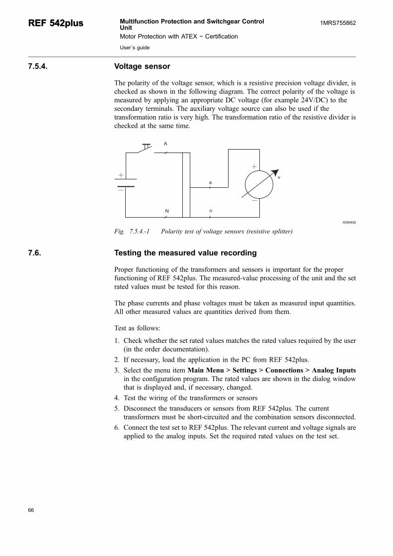
7.5.4. Voltage sensor
The polarity of the voltage sensor, which is a resistive precision voltage divider, ischecked as shown in the following diagram. The correct polarity of the voltage ismeasured by applying an appropriate DC voltage (for example 24V/DC) to thesecondary terminals. The auxiliary voltage source can also be used if thetransformation ratio is very high. The transformation ratio of the resistive divider ischecked at the same time.
�
�
�
�
A050492
Fig. 7.5.4.-1 Polarity test of voltage sensors (resistive splitter)
7.6. Testing the measured value recording
Proper functioning of the transformers and sensors is important for the properfunctioning of REF 542plus. The measured-value processing of the unit and the setrated values must be tested for this reason.
The phase currents and phase voltages must be taken as measured input quantities.All other measured values are quantities derived from them.
Test as follows:
1. Check whether the set rated values matches the rated values required by the user(in the order documentation).
2. If necessary, load the application in the PC from REF 542plus.
3. Select the menu item Main Menu > Settings > Connections > Analog Inputsin the configuration program. The rated values are shown in the dialog windowthat is displayed and, if necessary, changed.
4. Test the wiring of the transformers or sensors
5. Disconnect the transducers or sensors from REF 542plus. The currenttransformers must be short-circuited and the combination sensors disconnected.
6. Connect the test set to REF 542plus. The relevant current and voltage signals areapplied to the analog inputs. Set the required rated values on the test set.
66
REF 542plusREF 542plus Multifunction Protection and Switchgear ControlUnit
Motor Protection with ATEX − Certification
User´s guide
1MRS755862
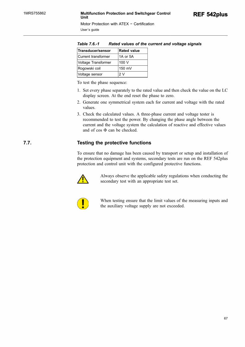
67
Table 7.6.-1 Rated values of the current and voltage signals
Transducer/sensor Rated value
Current transformer 1A or 5A
Voltage Transformer 100 V
Rogowski coil 150 mV
Voltage sensor 2 V
To test the phase sequence:
1. Set every phase separately to the rated value and then check the value on the LCdisplay screen. At the end reset the phase to zero.
2. Generate one symmetrical system each for current and voltage with the ratedvalues.
3. Check the calculated values. A three-phase current and voltage tester isrecommended to test the power. By changing the phase angle between thecurrent and the voltage system the calculation of reactive and effective valuesand of cos Φ can be checked.
7.7. Testing the protective functions
To ensure that no damage has been caused by transport or setup and installation ofthe protection equipment and systems, secondary tests are run on the REF 542plusprotection and control unit with the configured protective functions.
Always observe the applicable safety regulations when conducting thesecondary test with an appropriate test set.
When testing ensure that the limit values of the measuring inputs andthe auxiliary voltage supply are not exceeded.
Multifunction Protection and Switchgear ControlUnit
Motor Protection with ATEX − Certification
User´s guide
REF 542plusREF 542plus1MRS755862

68
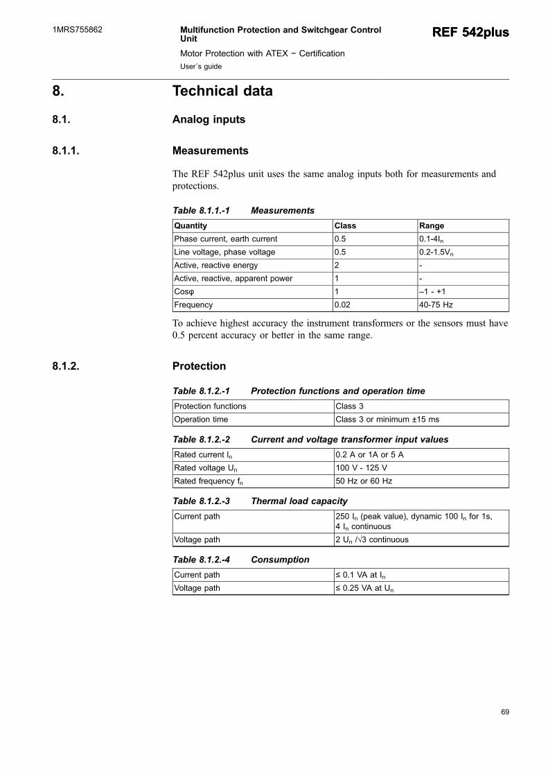
69
8. Technical data
8.1. Analog inputs
8.1.1. Measurements
The REF 542plus unit uses the same analog inputs both for measurements andprotections.
Table 8.1.1.-1 Measurements
Quantity Class Range
Phase current, earth current 0.5 0.1-4In
Line voltage, phase voltage 0.5 0.2-1.5Vn
Active, reactive energy 2 -
Active, reactive, apparent power 1 -
Cosφ 1 –1 - +1
Frequency 0.02 40-75 Hz
To achieve highest accuracy the instrument transformers or the sensors must have0.5 percent accuracy or better in the same range.
8.1.2. Protection
Table 8.1.2.-1 Protection functions and operation time
Protection functions Class 3
Operation time Class 3 or minimum ±15 ms
Table 8.1.2.-2 Current and voltage transformer input values
Rated current ln 0.2 A or 1A or 5 A
Rated voltage Un 100 V - 125 V
Rated frequency fn 50 Hz or 60 Hz
Table 8.1.2.-3 Thermal load capacity
Current path 250 In (peak value), dynamic 100 In for 1s,4 In continuous
Voltage path 2 Un /√3 continuous
Table 8.1.2.-4 Consumption
Current path ≤ 0.1 VA at In
Voltage path ≤ 0.25 VA at Un
Multifunction Protection and Switchgear ControlUnit
Motor Protection with ATEX − Certification
User´s guide
REF 542plusREF 542plus1MRS755862
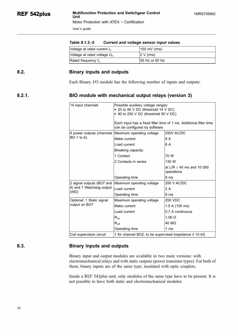
Table 8.1.2.-5 Current and voltage sensor input values
Voltage at rated current In 150 mV (rms)
Voltage at rated voltage Un 2 V (rms)
Rated frequency fn 50 Hz or 60 Hz
8.2. Binary inputs and outputs
Each Binary I/O module has the following number of inputs and outputs:
8.2.1. BIO module with mechanical output relays (version 3)
14 input channels Possible auxiliary voltage ranges:* 20 to 90 V DC (threshold 14 V DC)* 80 to 250 V DC (threshold 50 V DC)
Each input has a fixed filter time of 1 ms. Additional filter timecan be configured by software.
6 power outputs (channelsBO 1 to 6).
Maximum operating voltage 250V AC/DC
Make current 8 A
Load current 6 A
Breaking capacity:
1 Contact 70 W
2 Contacts in series 130 W
at L/R ≤ 40 ms and 10 000operations
Operating time 8 ms
2 signal outputs (BO7 and8) and 1 Watchdog output(WD)
Maximum operating voltage 250 V AC/DC
Load current 2 A
Operating time 8 ms
Optional: 1 Static signaloutput on BO7
Maximum operating voltage 250 VDC
Make current 1.5 A (100 ms)
Load current 0.7 A continuous
Ron 1,06 Ω
Roff 40 MΩ
Operating time 1 ms
Coil supervision circuit 1 for channel BO2, to be supervised impedance ≤ 10 kΩ
8.3. Binary inputs and outputs
Binary input and output modules are available in two main versions: withelectromechanical relays and with static outputs (power transistor types). For both ofthem, binary inputs are of the same type, insulated with optic couplers.
Inside a REF 542plus unit, only modules of the same type have to be present. It isnot possible to have both static and electromechanical modules.
70
REF 542plusREF 542plus Multifunction Protection and Switchgear ControlUnit
Motor Protection with ATEX − Certification
User´s guide
1MRS755862
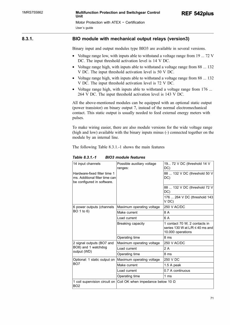
71
8.3.1. BIO module with mechanical output relays (version3)
Binary input and output modules type BIO3 are available in several versions.
* Voltage range low, with inputs able to withstand a voltage range from 19 ... 72 VDC. The input threshold activation level is 14 V DC.
* Voltage range high, with inputs able to withstand a voltage range from 88 ... 132V DC. The input threshold activation level is 50 V DC.
* Voltage range high, with inputs able to withstand a voltage range from 88 ... 132V DC. The input threshold activation level is 72 V DC.
* Voltage range high, with inputs able to withstand a voltage range from 176 ...264 V DC. The input threshold activation level is 143 V DC.
All the above-mentioned modules can be equipped with an optional static output(power transistor) on binary output 7, instead of the normal electromechanicalcontact. This static output is usually needed to feed external energy meters withpulses.
To make wiring easier, there are also module versions for the wide voltage range(high and low) available with the binary inputs minus (-) connected together on themodule by an internal line.
The following Table 8.3.1.-1 shows the main features
Table 8.3.1.-1 BIO3 module features
14 input channels Possible auxiliary voltageranges:
19... 72 V DC (threshold 14 VDC)
Hardware-fixed filter time 1ms. Additional filter time canbe configured in software.
88 ... 132 V DC (threshold 50 VDC)
88 ... 132 V DC (threshold 72 VDC)
176 ... 264 V DC (threshold 143V DC)
6 power outputs (channelsBO 1 to 6)
Maximum operating voltage 250 V AC/DC
Make current 8 A
Load current 6 A
Breaking capacity 1 contact 70 W, 2 contacts inseries 130 W at L/R ≤ 40 ms and10.000 operations
Operating time 8 ms
2 signal outputs (BO7 andBO8) and 1 watchdogoutput (WD)
Maximum operating voltage 250 V AC/DC
Load current 2 A
Operating time 8 ms
Optional: 1 static output onBO7
Maximum operating voltage 250 V DC
Make current 1.5 A peak
Load current 0.7 A continuous
Operating time 1 ms
1 coil supervision circuit onBO2
Coil OK when impedance below 10 Ω
Multifunction Protection and Switchgear ControlUnit
Motor Protection with ATEX − Certification
User´s guide
REF 542plusREF 542plus1MRS755862

8.3.2. BIO module with static outputs
The technical data for the binary input and output module with static outputs arelisted in Table 8.3.2.-1. This module is full range and covers the complete voltagerange from 48 up to 265 VDC.
Table 8.3.2.-1 Technical data for the binary input and output module withstatic outputs
14 inputs (BI 1–14).Hardware-fixed filter time 5ms. Additional filter time canbe configured in software.
Auxiliary voltage range: 48 to 265 V DC (Threshold356 V DC)
3 power outputs (BO1,2 andþ7)
Operating voltage 48 to 250 V DC
Make current 64 A
Load current 16 A
Operating time 1 ms
4 power outputs (BO3...6) Operating voltage 48 to 250 V DC
Make current 120 A
Load current 31 A
Operating time 1 ms
2 signal outputs (BO8,9) and1 watchdog output (WD)
Operating voltage 48 to 250 V DC
Make current 1.5 A (100 ms)
Ron 1.06 Ω
Roff 40 MΩ
Operating time 1 ms
2 coil supervision circuits onBO1 and BO2 channels
Coil OK when impendace below 10 kΩ
8.4. Interfaces
HMI control unit
* Serial infrared (IrDa)/electrical RS-232 interface to a PC (at the front)* Electrically isolated RS-485 standard interface to the base unit (at the rear)* Electrical standard-interface RJ-45 for Modbus TCP and/or the embedded WEB
server* Power supply
Base unit
* Electrically isolated RS-485 standard interface to the HMI* RS-232 standard service interface (service port for updating configuration and
firmware)* Power supply
72
REF 542plusREF 542plus Multifunction Protection and Switchgear ControlUnit
Motor Protection with ATEX − Certification
User´s guide
1MRS755862

73
0/4 ... 20 mA analog output module (optional)
* Four output channels 0 to 20 mA or 4 to 20 mA, freely configurable.
4 ... 20 mA analog input module (optional)
* Six input channels 4 ... 20 mA
Communication to a station automation system (optional)
* SPA, optical plastic fiber interface with a snap-in type connector; or glass fiber(multi-mode) with F-SMA or ST connectors
* LON (according to ABB LAG1.4), glass fiber (multi-mode) optical interfacewith ST connectors
* IEC 60870-5-103 with extension according to VDN guidelines for controlling,glass fiber (multi-mode) optical interface with ST connectors
* Modbus RTU/SPA bus electrical interface with two galvanically insulated SPA-bus RS-485 ports or optical interface with four standard ST connectors for glassfiber (multi-mode)
* IEC 61850 electrical interface with two RJ45 connectors or an optical interfacewith two LC connectors.
Ethernet Interface
* Standard RJ45 connector on the main module
CAN Open (optional and only for ABB switchgear companies).
* Open-style connector compliant with CAN Open standard and ISO11898
Input for time synchronization (optional, the supported protocolis IRIG, format B000, B002, B003).
* Glass fiber* Wavelength: 820 nm* Max distance: 1500 m* Connector type: ST
Multifunction Protection and Switchgear ControlUnit
Motor Protection with ATEX − Certification
User´s guide
REF 542plusREF 542plus1MRS755862

8.5. Power supply
Table 8.5.-1 Base unit
Rated voltage 110 V DC Operative range 70% to 120% of 110 V DC
Rated voltage 220 V DC Operative range 70% to 120% of 220 V DC
Rated voltage 48 VDC to 220 V DC Operative range 80% of 48 V DC to 120% of220 V DC
Power consumption ≤ 20 W (Typical, 2 BIOs)
Inrush current Module 750 168: 10 A, 1 ms; 35 A, 100 µsModule 750 126: 8.3 A, 4 ms; 21 A, 100 µs
Admissible ripple Less than 10%
Table 8.5.-2 HMI
Rated voltage 48 V DC to 90 V DC Operative range 85% of 48 V DC to 110% of90 V DC
Rated voltage 110 V DC to 240 V DC Operative range 85% of 110 V DC to 110% of240 V DC
Power consumption ≤ 6 W backlight off and < 10W backlight on
Admissible ripple Less than 10%
8.6. Environmental conditions
Table 8.6.-1 Environmental conditions
Ambient operation temperature -10 + 55 °C
Ambient transport and storagetemperature
-25 +70 °C
Ambient humidity Up to 95% without condensation
Altitude < 1.000m a.s.l
8.7. Protection degree
Base unit
* Housing: IP 20
HMI
* Front: IP 44 (IP 54 HMI version with cover)* Rear: IP 20
HMI with cover
* Front: IP 54* Rear: IP 20
74
REF 542plusREF 542plus Multifunction Protection and Switchgear ControlUnit
Motor Protection with ATEX − Certification
User´s guide
1MRS755862
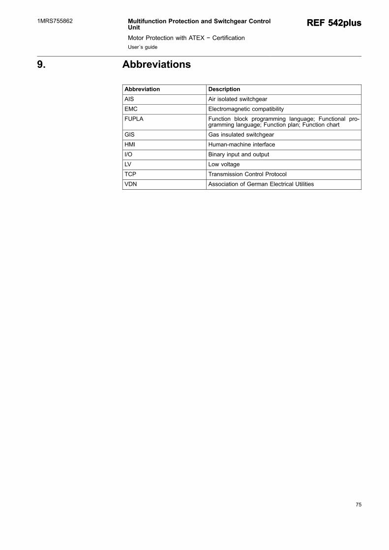
75
9. Abbreviations
Abbreviation Description
AIS Air isolated switchgear
EMC Electromagnetic compatibility
FUPLA Function block programming language; Functional pro-gramming language; Function plan; Function chart
GIS Gas insulated switchgear
HMI Human-machine interface
I/O Binary input and output
LV Low voltage
TCP Transmission Control Protocol
VDN Association of German Electrical Utilities
Multifunction Protection and Switchgear ControlUnit
Motor Protection with ATEX − Certification
User´s guide
REF 542plusREF 542plus1MRS755862

76
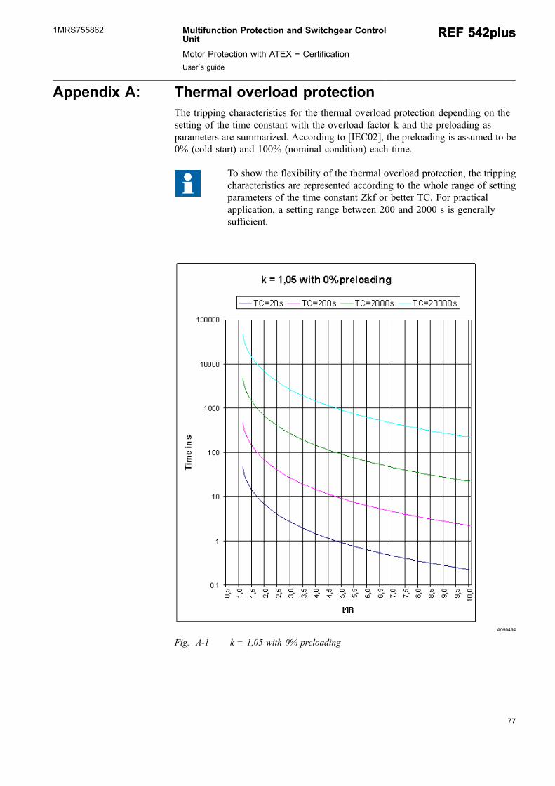
77
Appendix A: Thermal overload protectionThe tripping characteristics for the thermal overload protection depending on thesetting of the time constant with the overload factor k and the preloading asparameters are summarized. According to [IEC02], the preloading is assumed to be0% (cold start) and 100% (nominal condition) each time.
To show the flexibility of the thermal overload protection, the trippingcharacteristics are represented according to the whole range of settingparameters of the time constant Zkf or better TC. For practicalapplication, a setting range between 200 and 2000 s is generallysufficient.
A050494
Fig. A-1 k = 1,05 with 0% preloading
Multifunction Protection and Switchgear ControlUnit
Motor Protection with ATEX − Certification
User´s guide
REF 542plusREF 542plus1MRS755862
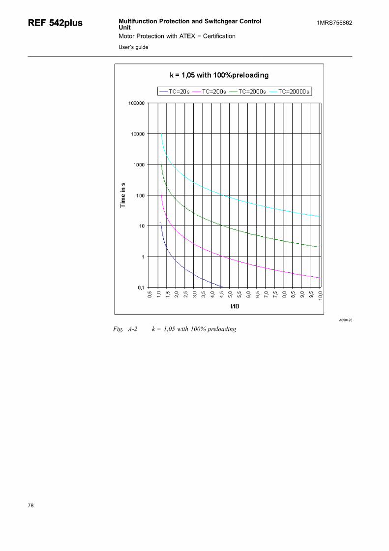
A050495
Fig. A-2 k = 1,05 with 100% preloading
78
REF 542plusREF 542plus Multifunction Protection and Switchgear ControlUnit
Motor Protection with ATEX − Certification
User´s guide
1MRS755862
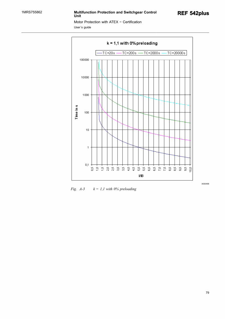
79
A050496
Fig. A-3 k = 1,1 with 0% preloading
Multifunction Protection and Switchgear ControlUnit
Motor Protection with ATEX − Certification
User´s guide
REF 542plusREF 542plus1MRS755862
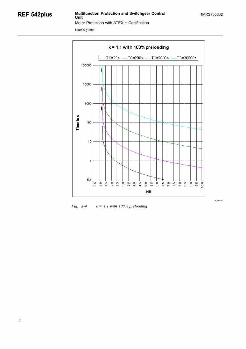
A050497
Fig. A-4 k = 1,1 with 100% preloading
80
REF 542plusREF 542plus Multifunction Protection and Switchgear ControlUnit
Motor Protection with ATEX − Certification
User´s guide
1MRS755862
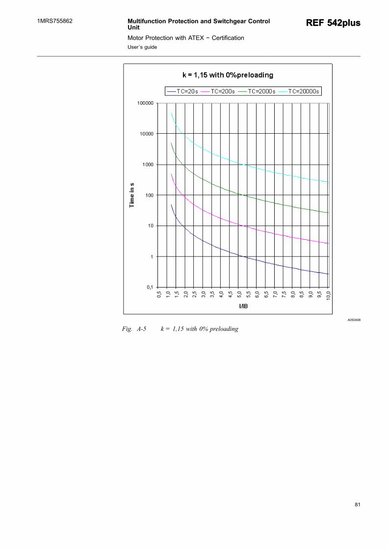
81
A050498
Fig. A-5 k = 1,15 with 0% preloading
Multifunction Protection and Switchgear ControlUnit
Motor Protection with ATEX − Certification
User´s guide
REF 542plusREF 542plus1MRS755862

A050499
Fig. A-6 k = 1,15 with 100% preloading
82
REF 542plusREF 542plus Multifunction Protection and Switchgear ControlUnit
Motor Protection with ATEX − Certification
User´s guide
1MRS755862
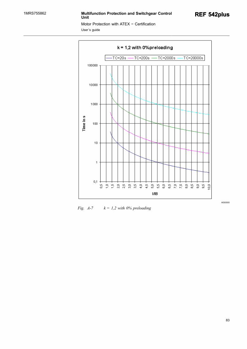
83
A050500
Fig. A-7 k = 1,2 with 0% preloading
Multifunction Protection and Switchgear ControlUnit
Motor Protection with ATEX − Certification
User´s guide
REF 542plusREF 542plus1MRS755862

A051052
Fig. A-8 k = 1,2 with 100% preloading
84
REF 542plusREF 542plus Multifunction Protection and Switchgear ControlUnit
Motor Protection with ATEX − Certification
User´s guide
1MRS755862


ABB OyDistribution AutomationP.O. Box 699FI-65101 VaasaFINLAND+358 10 22 11+358 10 22 224 1094http://www.abb.com/substationautomation
1MRS755862
EN
12/2009