Schneider Electric Lexium Motion Control Torque/Speed Curves · Lexium™ Motion Control...
68
Lexium ™ Motion Control Torque/Speed Curves 2014 Courtesy of Steven Engineering, Inc. - (800) 258-9200 - [email protected] - www.stevenengineering.com
Transcript of Schneider Electric Lexium Motion Control Torque/Speed Curves · Lexium™ Motion Control...

Lexium™ Motion Control Torque/Speed Curves
2014
Courtesy of Steven Engineering, Inc. - (800) 258-9200 - [email protected] - www.stevenengineering.com

2
1. Go to: www.schneider-electric.com and select “Products” on the “Products and Services” tab.
1
Go online to www.schneider-electric.com for information about Lexium™ products listed in this catalog, including:
1
2
2. On the “Products” page, find the “Motion Control” icon and select “All Motion Control”.
2
Courtesy of Steven Engineering, Inc. - (800) 258-9200 - [email protected] - www.stevenengineering.com

3
> Specifications > Dimensions > References> Curves > Links to user guides and CAD files
3 On the “Motion Control” page, select the family of products you are interested in. On each product page, you can find Product Information, Documents and Downloads, Support, and more.
3
3
Courtesy of Steven Engineering, Inc. - (800) 258-9200 - [email protected] - www.stevenengineering.com

4
Torque/speed curve diagram example
Mmax 1
2Meq
M0
nmax
Work zoneSpeed in rpm
navg
Torque in N•m
How to read the torque/speed curve diagramsEach motor/drive combination’s performance level is described using torque/speed curve profiles similar to the example shown below with:1 Peak torque, depending on the servo drive model2 Continuous torque, depending on the servo drive model where:
b nmax (in rpm) corresponds to the maximum speed of the servo motor b Mmax (in N•m) represents the peak stall torque value b M0 (in N•m) represents the continuous stall torque value
Use these torque/speed curves to determine the correct servo motor size:1 Locate the work zone of the application in terms of speed.2 Verify, using the servo motor cycle timing diagram, that the torques required by the application during the various phases of the cycle are located within the area bounded by curve 1 in the work zone.3 Calculate the average speed navg and the equivalent thermal torque Meq.4 The point defined by navg and Meq must be located below curve 2 in the work zone.
How to read the curves in this data bulletin
Lexium™ Motion Control Torque/Speed Curves
Courtesy of Steven Engineering, Inc. - (800) 258-9200 - [email protected] - www.stevenengineering.com

5
Contents Lexium™ Motion Control Torque/Speed Curves
Lexium 32 series b Overview . . . . . . . . . . . . . . . . . . . . . . . . . . . . . . . . . . . . . . . . . . . . . . . . . . . . . . . 7
b Selection guides. . . . . . . . . . . . . . . . . . . . . . . . . . . . . . . . . . . . . . . . . . . . . . . . . . 8
b Specifications and curves: v Lexium 32/BMH combinations . . . . . . . . . . . . . . . . . . . . . . . . . . . . . . . . . . . . 16 v Lexium 32/BSH combinations . . . . . . . . . . . . . . . . . . . . . . . . . . . . . . . . . . . . 34
Lexium 32i series b Overview . . . . . . . . . . . . . . . . . . . . . . . . . . . . . . . . . . . . . . . . . . . . . . . . . . . . . . 47
b Specifications and curves: v Lexium 32i integrated drives (BMI servo motors) . . . . . . . . . . . . . . . . . . . . . . 48
Lexium ILp series b Overview . . . . . . . . . . . . . . . . . . . . . . . . . . . . . . . . . . . . . . . . . . . . . . . . . . . . . . 53
b Specifications and curves: v Lexium ILp1 integrated drives . . . . . . . . . . . . . . . . . . . . . . . . . . . . . . . . . . . . 54 v Lexium ILp2 integrated drives . . . . . . . . . . . . . . . . . . . . . . . . . . . . . . . . . . . . 60
Courtesy of Steven Engineering, Inc. - (800) 258-9200 - [email protected] - www.stevenengineering.com

6Courtesy of Steven Engineering, Inc. - (800) 258-9200 - [email protected] - www.stevenengineering.com

7
OverviewThe Lexium 32 product range of servo drives includes 4 servo drive models associated with 2 servo motor ranges for optimum use that can adapt to demands for high performance, power, and simplicity of use in motion control applications. It covers power ratings from 0.15 to 11 kW.
The Lexium 32 product range of servo drives covers motor power ratings between 0.15 kW and 11 kW with three types of power supply:
b 110 to 120 V single-phase, 0.15 kW to 0.8 kW (LXM32ppppM2)b 200 to 240 V single-phase, 0.3 kW to 1.6 kW (LXM32ppppM2)b 208 to 480 V three-phase, 0.4 kW to 11 kW (LXM32ppppN4)
BMH and BSH servo motors are synchronous three-phase motors. They feature a SinCos Hiperface® encoder for automatic transmission of data from the servo motor to the servo drive and are available with or without a holding brake.
BMH servo motorsBMH servo motors are medium inertia motors. They are particularly suitable for high-load applications and allow the movement to be adjusted in a more robust manner.This product offer covers a continuous stall torque range from 1.2 N•m to 84 N•m for nominal speeds from 1,200 to 5,000 rpm.
BSH servo motorsBSH servo motors satisfy requirements for precision and high dynamic performance, due to the low rotor inertia. They are compact, and offer a high power density.This product offer covers a continuous stall torque range from 0.5 N•m to 33.4 N•m for nominal speeds from 2,500 to 6,000 rpm.
Lexium™ 32 series
Courtesy of Steven Engineering, Inc. - (800) 258-9200 - [email protected] - www.stevenengineering.com

8
Type of servo motor
Rotor inertia
Type of servo motor
Rotor inertia
Nominal torque
Nominal speed
Nominal power
M0/Mmax (2) Nominal torque Nominal speed Nominal power M0/Mmax (2) Nominal torque Nominal speed Nominal power M0/Mmax (2)
kgcm2 kgcm2 N•m rpm W N•m/N•m N•m rpm W N•m/N•m N•m rpm W N•m/N•mBSH0551T 0.06 0.49 3,000 150 0.5/1.5 34BSH0552T 0.10 0.77 3,000 250 0.8/1.9 34BSH0553T 0.13 1.14 3,000 350 1.2/3.3 34
BMH0701T 0.59 1.35 2,500 350 1.4/4.2 16BSH0701T 0.25 1.36 2,500 350 1.4/3.5 35BSH0702T 0.41 2.07 2,500 550 2.2/6.1 35
BMH0702T 1.13 2.3 2,500 600 2.5/6.4 16BMH0703T 1.67 3.1 2,000 650 3.4/8.7 16
BSH1001T 1.40 2.75 2,500 700 3.3/6.3 35BMH1001T 3.2 3.3 2,000 700 3.4/8.9 17BMH1002T 6.3 3.5 2,000 750 6/10.3 17
(1) These values are given for a supply voltage of 120 V single phase.(2) - M0: Continuous stall torque - Mmax: Peak stall torque
(1) These values are given for a supply voltage of 120 V single phase.(2) - M0: Continuous stall torque - Mmax: Peak stall torque
Lexium 32 servo drive/BMH or BSH servo motor combinationsServo motors Lexium 32C, 32A, 32M and 32S servo drives
100 to 120 V single-phase supply voltage with integrated EMC filter
Page Page PageBMH (IP 50 or IP 65)
BSH (IP 50 or IP 65)
LXM32pU90M2Continuous output current: 3 A rms
LXM32pD18M2Continuous output current: 6 A rms
LXM32pD30M2Continuous output current: 10 A rms
Nominal operating point (1) Stall torques Nominal operating point (1) Stall torques Nominal operating point (1) Stall torques
Lexium 32 seriesSelection guide
Lexium™ Motion Control Torque/Speed Curves100 to 120 V single-phase supply voltageServo drive/servo motor combinations
Courtesy of Steven Engineering, Inc. - (800) 258-9200 - [email protected] - www.stevenengineering.com

9
Type of servo motor
Rotor inertia
Type of servo motor
Rotor inertia
Nominal torque
Nominal speed
Nominal power
M0/Mmax (2) Nominal torque Nominal speed Nominal power M0/Mmax (2) Nominal torque Nominal speed Nominal power M0/Mmax (2)
kgcm2 kgcm2 N•m rpm W N•m/N•m N•m rpm W N•m/N•m N•m rpm W N•m/N•mBSH0551T 0.06 0.49 3,000 150 0.5/1.5 34BSH0552T 0.10 0.77 3,000 250 0.8/1.9 34BSH0553T 0.13 1.14 3,000 350 1.2/3.3 34
BMH0701T 0.59 1.35 2,500 350 1.4/4.2 16BSH0701T 0.25 1.36 2,500 350 1.4/3.5 35BSH0702T 0.41 2.07 2,500 550 2.2/6.1 35
BMH0702T 1.13 2.3 2,500 600 2.5/6.4 16BMH0703T 1.67 3.1 2,000 650 3.4/8.7 16
BSH1001T 1.40 2.75 2,500 700 3.3/6.3 35BMH1001T 3.2 3.3 2,000 700 3.4/8.9 17BMH1002T 6.3 3.5 2,000 750 6/10.3 17
(1) These values are given for a supply voltage of 120 V single phase.(2) - M0: Continuous stall torque - Mmax: Peak stall torque
(1) These values are given for a supply voltage of 120 V single phase.(2) - M0: Continuous stall torque - Mmax: Peak stall torque
Lexium 32 servo drive/BMH or BSH servo motor combinationsServo motors Lexium 32C, 32A, 32M and 32S servo drives
100 to 120 V single-phase supply voltage with integrated EMC filter
Page Page PageBMH (IP 50 or IP 65)
BSH (IP 50 or IP 65)
LXM32pU90M2Continuous output current: 3 A rms
LXM32pD18M2Continuous output current: 6 A rms
LXM32pD30M2Continuous output current: 10 A rms
Nominal operating point (1) Stall torques Nominal operating point (1) Stall torques Nominal operating point (1) Stall torques
Courtesy of Steven Engineering, Inc. - (800) 258-9200 - [email protected] - www.stevenengineering.com

10
Lexium 32 servo drive/BMH or BSH servo motor combinationsServo motors Lexium 32C, 32A, 32M and 32S servo drives
200 to 240 V single-phase supply voltage with integrated EMC filter
Page Page Page PageBMH(IP 50 or IP 65)
BSH(IP 50 or IP 65)
LXM32pU45M2Continuous output current: 1.5 A rms
LXM32pU90M2Continuous output current: 3 A rms
LXM32pD18M2Continuous output current: 6 A rms
LXM32pD30M2Continuous output current: 10 A rms
Nominal operating point (1) Stall torques Nominal operating point (1) Stall torques
Nominal operating point (1) Stall torques
Nominal operating point (1) Stall torques
Type of servo motor
Rotor inertia
Type of servo motor
Rotor inertia
Nominal torque
Nominal speed
Nominal power
M0/Mmax (2) Nominal torque
Nominal speed
Nominal power
M0/Mmax (2)
Nominal torque
Nominal speed
Nominal power
M0/Mmax (2)
Nominal torque
Nominal speed
Nominal power
M0/Mmax (2)
kgcm2 kgcm2 N•m rpm W N•m/N•m N•m rpm W N•m/N•m N•m rpm W N•m/N•m N•m rpm W N•m/N•mBSH0551T 0.06 0.45 6,000 300 0.5/1.4 36BSH0552T 0.10 0.74 6,000 450 0.8/2.5 36BSH0553T 0.13 0.84 6,000 550 1.2/3 36BSH0701T 0.25 0.94 5,000 500 1.3/3.5 37
BMH0701T 0.59 1.1 4,000 450 1.4/4 18BSH0702T 0.41 1.8 5,000 950 2.2/7.2 37BSH0703T 0.58 2.1 4,000 900 2.6/7.4 37
BMH0702T 1.13 2.1 4,000 900 2.5/7.4 18BSH1001T 1.40 2.2 4,000 900 2.7/7.5 38
BMH0703T 1.67 2.9 3,000 900 3.4/10.2 18BMH1001T 3.2 2.8 3,000 900 3.4/10.2 19
BSH1002T 2.31 3.7 4,000 1,500 5.8/16.4 38BMH1002T 6.3 4.6 3,000 1,450 6/18.4 19BMH1003T 9.4 5.6 2,500 1,450 8/23.5 19BMH1401P 16.5 8.9 1,500 1,450 10.3/30.8 19
(1) These values are given for a supply voltage of 240 V single phase.(2) - M0: Continuous stall torque - Mmax: Peak stall torque
(1) These values are given for a supply voltage of 240 V single phase.(2) - M0: Continuous stall torque - Mmax: Peak stall torque
Lexium 32 series Selection guide (continued)
Lexium™ Motion Control Torque/Speed Curves200 to 240 V single-phase supply voltageServo drive/servo motor combinations
Courtesy of Steven Engineering, Inc. - (800) 258-9200 - [email protected] - www.stevenengineering.com

11
Lexium 32 servo drive/BMH or BSH servo motor combinationsServo motors Lexium 32C, 32A, 32M and 32S servo drives
200 to 240 V single-phase supply voltage with integrated EMC filter
Page Page Page PageBMH(IP 50 or IP 65)
BSH(IP 50 or IP 65)
LXM32pU45M2Continuous output current: 1.5 A rms
LXM32pU90M2Continuous output current: 3 A rms
LXM32pD18M2Continuous output current: 6 A rms
LXM32pD30M2Continuous output current: 10 A rms
Nominal operating point (1) Stall torques Nominal operating point (1) Stall torques
Nominal operating point (1) Stall torques
Nominal operating point (1) Stall torques
Type of servo motor
Rotor inertia
Type of servo motor
Rotor inertia
Nominal torque
Nominal speed
Nominal power
M0/Mmax (2) Nominal torque
Nominal speed
Nominal power
M0/Mmax (2)
Nominal torque
Nominal speed
Nominal power
M0/Mmax (2)
Nominal torque
Nominal speed
Nominal power
M0/Mmax (2)
kgcm2 kgcm2 N•m rpm W N•m/N•m N•m rpm W N•m/N•m N•m rpm W N•m/N•m N•m rpm W N•m/N•mBSH0551T 0.06 0.45 6,000 300 0.5/1.4 36BSH0552T 0.10 0.74 6,000 450 0.8/2.5 36BSH0553T 0.13 0.84 6,000 550 1.2/3 36BSH0701T 0.25 0.94 5,000 500 1.3/3.5 37
BMH0701T 0.59 1.1 4,000 450 1.4/4 18BSH0702T 0.41 1.8 5,000 950 2.2/7.2 37BSH0703T 0.58 2.1 4,000 900 2.6/7.4 37
BMH0702T 1.13 2.1 4,000 900 2.5/7.4 18BSH1001T 1.40 2.2 4,000 900 2.7/7.5 38
BMH0703T 1.67 2.9 3,000 900 3.4/10.2 18BMH1001T 3.2 2.8 3,000 900 3.4/10.2 19
BSH1002T 2.31 3.7 4,000 1,500 5.8/16.4 38BMH1002T 6.3 4.6 3,000 1,450 6/18.4 19BMH1003T 9.4 5.6 2,500 1,450 8/23.5 19BMH1401P 16.5 8.9 1,500 1,450 10.3/30.8 19
(1) These values are given for a supply voltage of 240 V single phase.(2) - M0: Continuous stall torque - Mmax: Peak stall torque
(1) These values are given for a supply voltage of 240 V single phase.(2) - M0: Continuous stall torque - Mmax: Peak stall torque
Courtesy of Steven Engineering, Inc. - (800) 258-9200 - [email protected] - www.stevenengineering.com
12
Lexium 32 seriesSelection guide (continued)
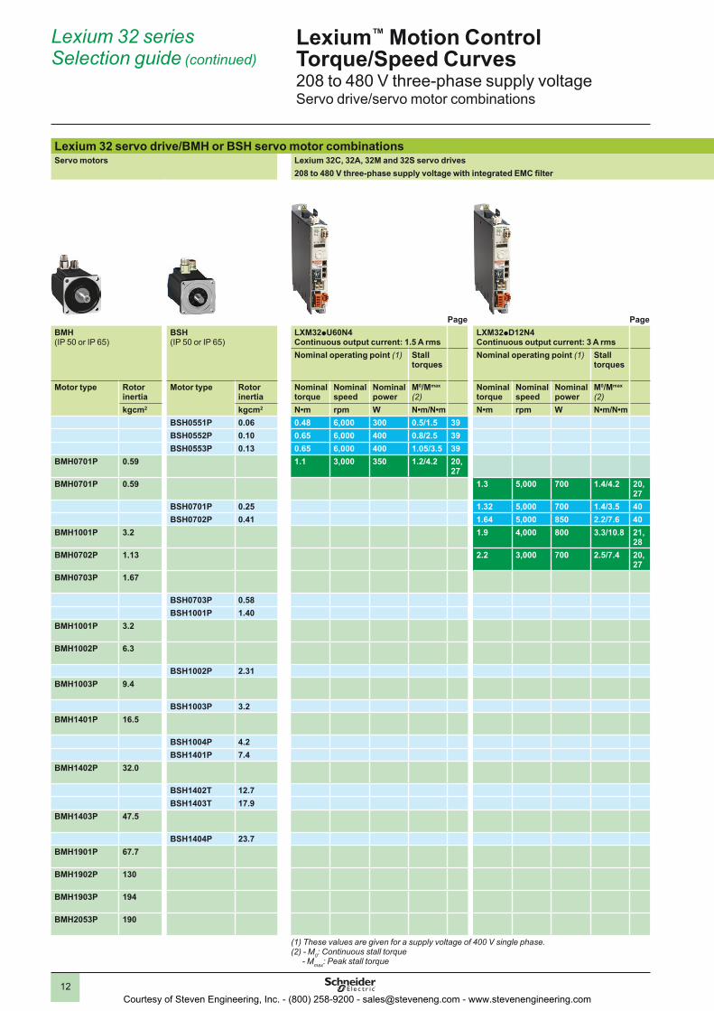
Lexium™ Motion Control Torque/Speed Curves208 to 480 V three-phase supply voltageServo drive/servo motor combinations
Lexium 32 servo drive/BMH or BSH servo motor combinationsServo motors Lexium 32C, 32A, 32M and 32S servo drives
208 to 480 V three-phase supply voltage with integrated EMC filter
Page Page Page Page PageBMH(IP 50 or IP 65)
BSH(IP 50 or IP 65)
LXM32pU60N4Continuous output current: 1.5 A rms
LXM32pD12N4Continuous output current: 3 A rms
LXM32pD18N4Continuous output current: 6 A rms
LXM32pD30N4Continuous output current: 10 A rms
LXM32pD72N4 Continuous output current: 24 A rms
Nominal operating point (1) Stall torques
Nominal operating point (1) Stall torques
Nominal operating point (1) Stall torques
Nominal operating point (1) Stall torques
Nominal operating point (1) Stall torques
Motor type Rotor inertia
Motor type Rotor inertia
Nominal torque
Nominal speed
Nominal power
M0/Mmax
(2)Nominal torque
Nominal speed
Nominal power
M0/Mmax
(2)Nominal torque
Nominal speed
Nominal power
M0/Mmax
(2)Nominal torque
Nominal speed
Nominal power
M0/Mmax
(2)Nominal torque
Nominal speed
Nominal power
M0/Mmax
(2)kgcm2 kgcm2 N•m rpm W N•m/N•m N•m rpm W N•m/N•m N•m rpm W N•m/N•m N•m rpm W N•m N•m rpm W N•m
BSH0551P 0.06 0.48 6,000 300 0.5/1.5 39BSH0552P 0.10 0.65 6,000 400 0.8/2.5 39BSH0553P 0.13 0.65 6,000 400 1.05/3.5 39
BMH0701P 0.59 1.1 3,000 350 1.2/4.2 20, 27
BMH0701P 0.59 1.3 5,000 700 1.4/4.2 20, 27
BSH0701P 0.25 1.32 5,000 700 1.4/3.5 40BSH0702P 0.41 1.64 5,000 850 2.2/7.6 40
BMH1001P 3.2 1.9 4,000 800 3.3/10.8 21, 28
BMH0702P 1.13 2.2 3,000 700 2.5/7.4 20, 27
BMH0703P 1.67 2.4 5,000 1,300 3.4/10.2 20, 27
BSH0703P 0.58 2.44 5,000 1,300 3.1/11.3 40BSH1001P 1.40 2.7 4,000 1,100 3.3/9.6 41
BMH1001P 3.2 3.1 4,000 1,300 3.4/10.2 21, 28
BMH1002P 6.3 3.9 4,000 1,600 5.9/18.4 21, 28
BSH1002P 2.31 4 4,000 1,700 5.8/18.3 41BMH1003P 9.4 6.2 4,000 2,600 8.4/25.1 21,
28BSH1003P 3.2 6.3 3,000 2,000 8/28.3 41
BMH1401P 16.5 7.6 3,000 2,400 10.3/30.8 22, 29
BSH1004P 4.2 8.3 2,500 2,100 10/37.9 41BSH1401P 7.4 9.5 2,500 2,500 11.1/27 42
BMH1402P 32.0 12.1 3,000 3,800 16.8/50.3 22, 29
BSH1402T 12.7 12.3 3,000 3,900 19.5/59.3 42BSH1403T 17.9 12.9 3,000 4,100 27.8/90.2 42
BMH1403P 47.5 14.2 3,000 4,500 24/71.8 22, 29
BSH1404P 23.7 19 2,500 5,000 33.4/103.6 42BMH1901P 67.7 18.4 2,500 4,800 30/77.7 23,
30BMH1902P 130 22.3 2,500 5,900 37.4/101 23,
30BMH1903P 194 36 1,500 5,700 43.2/123 23,
30BMH2053P 190 52.2 1,200 6,500 84/232 26,
33(1) These values are given for a supply voltage of 400 V single phase.(2) - M0: Continuous stall torque - Mmax: Peak stall torque
(1) These values are given for a supply voltage of 400 V single phase.(2) - M0: Continuous stall torque - Mmax: Peak stall torque
Courtesy of Steven Engineering, Inc. - (800) 258-9200 - [email protected] - www.stevenengineering.com

13
Lexium 32 servo drive/BMH or BSH servo motor combinationsServo motors Lexium 32C, 32A, 32M and 32S servo drives
208 to 480 V three-phase supply voltage with integrated EMC filter
Page Page Page Page PageBMH(IP 50 or IP 65)
BSH(IP 50 or IP 65)
LXM32pU60N4Continuous output current: 1.5 A rms
LXM32pD12N4Continuous output current: 3 A rms
LXM32pD18N4Continuous output current: 6 A rms
LXM32pD30N4Continuous output current: 10 A rms
LXM32pD72N4 Continuous output current: 24 A rms
Nominal operating point (1) Stall torques
Nominal operating point (1) Stall torques
Nominal operating point (1) Stall torques
Nominal operating point (1) Stall torques
Nominal operating point (1) Stall torques
Motor type Rotor inertia
Motor type Rotor inertia
Nominal torque
Nominal speed
Nominal power
M0/Mmax
(2)Nominal torque
Nominal speed
Nominal power
M0/Mmax
(2)Nominal torque
Nominal speed
Nominal power
M0/Mmax
(2)Nominal torque
Nominal speed
Nominal power
M0/Mmax
(2)Nominal torque
Nominal speed
Nominal power
M0/Mmax
(2)kgcm2 kgcm2 N•m rpm W N•m/N•m N•m rpm W N•m/N•m N•m rpm W N•m/N•m N•m rpm W N•m N•m rpm W N•m
BSH0551P 0.06 0.48 6,000 300 0.5/1.5 39BSH0552P 0.10 0.65 6,000 400 0.8/2.5 39BSH0553P 0.13 0.65 6,000 400 1.05/3.5 39
BMH0701P 0.59 1.1 3,000 350 1.2/4.2 20, 27
BMH0701P 0.59 1.3 5,000 700 1.4/4.2 20, 27
BSH0701P 0.25 1.32 5,000 700 1.4/3.5 40BSH0702P 0.41 1.64 5,000 850 2.2/7.6 40
BMH1001P 3.2 1.9 4,000 800 3.3/10.8 21, 28
BMH0702P 1.13 2.2 3,000 700 2.5/7.4 20, 27
BMH0703P 1.67 2.4 5,000 1,300 3.4/10.2 20, 27
BSH0703P 0.58 2.44 5,000 1,300 3.1/11.3 40BSH1001P 1.40 2.7 4,000 1,100 3.3/9.6 41
BMH1001P 3.2 3.1 4,000 1,300 3.4/10.2 21, 28
BMH1002P 6.3 3.9 4,000 1,600 5.9/18.4 21, 28
BSH1002P 2.31 4 4,000 1,700 5.8/18.3 41BMH1003P 9.4 6.2 4,000 2,600 8.4/25.1 21,
28BSH1003P 3.2 6.3 3,000 2,000 8/28.3 41
BMH1401P 16.5 7.6 3,000 2,400 10.3/30.8 22, 29
BSH1004P 4.2 8.3 2,500 2,100 10/37.9 41BSH1401P 7.4 9.5 2,500 2,500 11.1/27 42
BMH1402P 32.0 12.1 3,000 3,800 16.8/50.3 22, 29
BSH1402T 12.7 12.3 3,000 3,900 19.5/59.3 42BSH1403T 17.9 12.9 3,000 4,100 27.8/90.2 42
BMH1403P 47.5 14.2 3,000 4,500 24/71.8 22, 29
BSH1404P 23.7 19 2,500 5,000 33.4/103.6 42BMH1901P 67.7 18.4 2,500 4,800 30/77.7 23,
30BMH1902P 130 22.3 2,500 5,900 37.4/101 23,
30BMH1903P 194 36 1,500 5,700 43.2/123 23,
30BMH2053P 190 52.2 1,200 6,500 84/232 26,
33(1) These values are given for a supply voltage of 400 V single phase.(2) - M0: Continuous stall torque - Mmax: Peak stall torque
(1) These values are given for a supply voltage of 400 V single phase.(2) - M0: Continuous stall torque - Mmax: Peak stall torque
Courtesy of Steven Engineering, Inc. - (800) 258-9200 - [email protected] - www.stevenengineering.com

14
Lexium 32 seriesSelection guide (continued)
Lexium™ Motion Control Torque/Speed Curves208 to 480 V three-phase supply voltageServo drive/servo motor combinations
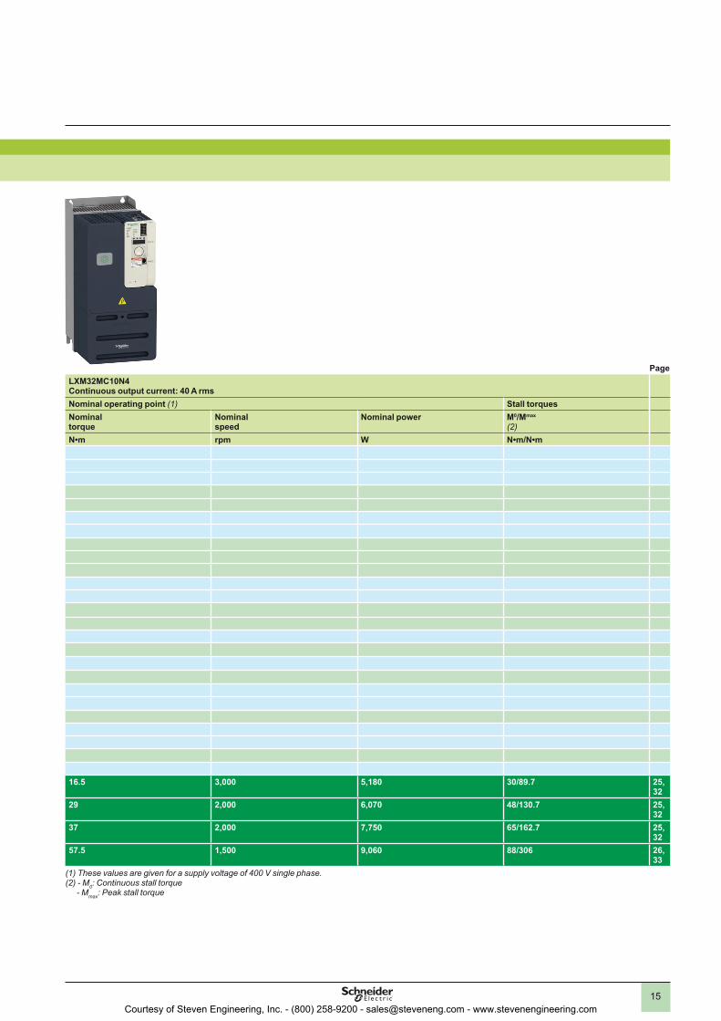
Lexium 32 servo drive/BMH or BSH servo motor combinationsServo motors Lexium 32M servo drives
208 to 480 V three-phase supply voltage with integrated EMC filter
Page PageBMH(IP 50 or IP 65)
BSH(IP 50 or IP 65)
LXM32MD85N4Continuous output current: 32 A rms
LXM32MC10N4Continuous output current: 40 A rms
Nominal operating point (1) Stall torques Nominal operating point (1) Stall torquesMotor type Rotor
inertiaMotor type Rotor
inertiaNominal torque
Nominal speed
Nominal power M0/Mmax
(2)Nominal torque
Nominal speed
Nominal power M0/Mmax
(2)kgcm2 kgcm2 N•m rpm W N•m/N•m N•m rpm W N•m/N•m
BSH0551P 0.06BSH0552P 0.10BSH0553P 0.13
BMH0701P 0.59BMH0701P 0.59
BSH0701P 0.25BSH0702P 0.41
BMH1001P 3.2BMH0702P 1.13BMH0703P 1.67
BSH0703P 0.58BSH1001P 1.40
BMH1001P 3.2BMH1002P 6.3
BSH1002P 2.31BMH1003P 9.4
BSH1003P 3.2BMH1401P 16.5
BSH1004P 4.2BSH1401P 7.4
BMH1402P 32.0BSH1402T 12.7BSH1403T 17.9
BMH1403P 47.5BSH1404P 23.7
BMH1901P 67.7 16.5 3,000 5,180 30/86.6 24, 31
16.5 3,000 5,180 30/89.7 25, 32
BMH1902P 130 29 2,000 6,070 48/115.5 24, 31
29 2,000 6,070 48/130.7 25, 32
BMH1903P 194 35 2,000 7,330 57.6/141.3 24, 31
37 2,000 7,750 65/162.7 25, 32
BMH2053P 190 53 1,500 8,330 88/266 26, 33
57.5 1,500 9,060 88/306 26, 33
(1) These values are given for a supply voltage of 400 V single phase.(2) - M0: Continuous stall torque - Mmax: Peak stall torque
(1) These values are given for a supply voltage of 400 V single phase.(2) - M0: Continuous stall torque - Mmax: Peak stall torque
Courtesy of Steven Engineering, Inc. - (800) 258-9200 - [email protected] - www.stevenengineering.com
15
Lexium 32 servo drive/BMH or BSH servo motor combinationsServo motors Lexium 32M servo drives
208 to 480 V three-phase supply voltage with integrated EMC filter
Page PageBMH(IP 50 or IP 65)
BSH(IP 50 or IP 65)
LXM32MD85N4Continuous output current: 32 A rms
LXM32MC10N4Continuous output current: 40 A rms
Nominal operating point (1) Stall torques Nominal operating point (1) Stall torquesMotor type Rotor
inertiaMotor type Rotor
inertiaNominal torque
Nominal speed
Nominal power M0/Mmax
(2)Nominal torque
Nominal speed
Nominal power M0/Mmax
(2)kgcm2 kgcm2 N•m rpm W N•m/N•m N•m rpm W N•m/N•m
BSH0551P 0.06BSH0552P 0.10BSH0553P 0.13
BMH0701P 0.59BMH0701P 0.59
BSH0701P 0.25BSH0702P 0.41
BMH1001P 3.2BMH0702P 1.13BMH0703P 1.67
BSH0703P 0.58BSH1001P 1.40
BMH1001P 3.2BMH1002P 6.3
BSH1002P 2.31BMH1003P 9.4
BSH1003P 3.2BMH1401P 16.5
BSH1004P 4.2BSH1401P 7.4
BMH1402P 32.0BSH1402T 12.7BSH1403T 17.9
BMH1403P 47.5BSH1404P 23.7
BMH1901P 67.7 16.5 3,000 5,180 30/86.6 24, 31
16.5 3,000 5,180 30/89.7 25, 32
BMH1902P 130 29 2,000 6,070 48/115.5 24, 31
29 2,000 6,070 48/130.7 25, 32
BMH1903P 194 35 2,000 7,330 57.6/141.3 24, 31
37 2,000 7,750 65/162.7 25, 32
BMH2053P 190 53 1,500 8,330 88/266 26, 33
57.5 1,500 9,060 88/306 26, 33
(1) These values are given for a supply voltage of 400 V single phase.(2) - M0: Continuous stall torque - Mmax: Peak stall torque
(1) These values are given for a supply voltage of 400 V single phase.(2) - M0: Continuous stall torque - Mmax: Peak stall torque
Courtesy of Steven Engineering, Inc. - (800) 258-9200 - [email protected] - www.stevenengineering.com

16
Lexium 32 seriesSpecifications and curves
Lexium™ Motion Control Torque/Speed CurvesLexium 32 servo drives/BMH servo motors115 V single-phase supply voltage
BMH 070 pp servo motorType of servo motor BMH 070 1T BMH 070 2T BMH 070 3TAssociated with Lexium 32 servo drive LXM 32pD18M2 LXM 32pD30M2
Switching frequency kHz 8Torque Continuous stall M0 N•m 1.4 2.5 3.4
Peak stall Mmax N•m 4.2 6.4 8.7Nominal operating point
Nominal torque N•m 1.35 2.3 3.1Nominal speed rpm 2500 2000Nominal servo motor output power
W 350 600 650
Maximum current A rms 9.6 15
Servo motor specificationsMaximum mechanical speed rpm 8000Constants(at 120°C)
Torque N•m/A rms 0.49 0.46 0.61Back emf V rms/
krpm31.7 29.6 39.3
Rotor Number of poles 10Inertia Without
brakeJm kgcm2 0.59 1.13 1.67
With brake Jm kgcm2 0.7 1.24 1.78
Stator(at 20°C)
Resistance (phase/phase) W 3.2 1.15 1.32Inductance (phase/phase) mH 9.1 3.6 4.3
Torque/speed curves (For information on how to read these curves, please refer to the guide on page 5.)BMH 070 1T servo motor BMH 070 2T servo motor
With LXM 32pD18M2 servo drive With LXM 32pD30M2 servo drive
BMH 070 3T servo motor With LXM 32pD30M2 servo drive
1 Peak torque2 Continuous torque
Mmax
M0
0 1000 2000 3000 40000
1
2
00,51,0
2,0
3,02,5
3,5
4,5Torque in N•m
Speed in rpm
Mmax
M0
0 1000 2000 3000 40000
1
2
4
3
5
6
7
2
1
Torque in N•m
Speed in rpm
Mmax
M0
0 1000 2000 3000 40000123
65
789
1
2
Torque in N•m
Speed in rpm
Courtesy of Steven Engineering, Inc. - (800) 258-9200 - [email protected] - www.stevenengineering.com

17
Lexium 32 seriesSpecifications and curves(continued)
Lexium™ Motion Control Torque/Speed CurvesLexium 32 servo drives/BMH servo motors115 V single-phase supply voltage
BMH 100 pp servo motorType of servo motor BMH 100 1T BMH 100 2TAssociated with Lexium 32 servo drive LXM 32pD30M2
Switching frequency kHz 8Torque Continuous stall M0 N•m 3.4 6
Peak stall Mmax N•m 8.9 10.3Nominal operating point
Nominal torque N•m 3.3 3.5Nominal speed rpm 2000Nominal servo motor output power
W 700 750
Maximum current A rms 15
Servo motor specificationsMaximum mechanical speed rpm 6000Constants(at 120°C)
Torque N•m/A rms 0.67 0.72Back emf V rms/
krpm43.3 46.2
Rotor Number of poles 10Inertia Without
brakeJm kgcm2 3.19 6.28
With brake Jm kgcm2 3.68 6.77
Stator(at 20°C)
Resistance (phase/phase) W 1.19 0.54Inductance (phase/phase) mH 5.3 2.7
Torque/speed curves (For information on how to read these curves, please refer to the guide on page 5.)BMH 100 1T servo motor BMH 100 2T servo motor
With LXM 32pD30M2 servo drive With LXM 32pD30M2 servo drive
1 Peak torque2 Continuous torque
Torque in N•m
Speed in rpm
Torque in N•m
Speed in rpm
Mmax
M0
0 1000 2000 3000012
4
65
789
1
2
1000 2000 3000
Mmax
M0
1
00
2
8
4
12
2
Courtesy of Steven Engineering, Inc. - (800) 258-9200 - [email protected] - www.stevenengineering.com

18
Lexium 32 seriesSpecifications and curves(continued)
Lexium™ Motion Control Torque/Speed CurvesLexium 32 servo drives/BMH servo motors230 V single-phase supply voltage
BMH 070 pp servo motorType of servo motor BMH 070 1T BMH 070 2T BMH 070 3TAssociated with Lexium 32 servo drive LXM 32pU90M2 LXM 32pD18M2
Switching frequency kHz 8Torque Continuous stall M0 N•m 1.4 2.5 3.4
Peak stall Mmax N•m 4 7.4 10.2Nominal operating point
Nominal torque N•m 1.1 2.1 2.9Nominal speed rpm 4000 3000Nominal servo motor output power
W 450 900
Maximum current A rms 9.6 17.7 17.8
Servo motor specificationsMaximum mechanical speed rpm 8000Constants(at 120°C)
Torque N•m/A rms 0.49 0.46 0.61Back emf V rms/
krpm31.7 29.6 39.3
Rotor Number of poles 10Inertia Without
brakeJm kgcm2 0.59 1.13 1.67
With brake Jm kgcm2 0.7 1.24 1.78
Stator(at 20°C)
Resistance (phase/phase) W 3.2 1.15 1.32Inductance (phase/phase) mH 9.1 3.6 4.3
Torque/speed curves (For information on how to read these curves, please refer to the guide on page 5.)BMH 070 1T servo motor BMH 070 2T servo motor
With LXM 32pU90M2 servo drive With LXM 32pD18M2 servo drive
BMH 070 3T servo motor With LXM 32pD18M2 servo drive
1 Peak torque2 Continuous torque
Torque in N•m
Speed in rpm
Torque in N•m
Speed in rpm
Torque in N•m
Speed in rpm
Mmax
M0
4000 6000 800000
2000
0,51,0
2,0
3,02,5
3,5
4,5 1
2
Mmax
M0
0 2000 4000 6000 800001
43
67
5
8
2
1
Mmax
M0
1
00
2
8
6
12
2
2000 4000 6000 8000
Courtesy of Steven Engineering, Inc. - (800) 258-9200 - [email protected] - www.stevenengineering.com

19
Lexium 32 seriesSpecifications and curves(continued)
Lexium™ Motion Control Torque/Speed CurvesLexium 32 servo drives/BMH servo motors230 V single-phase supply voltage
BMH 100/140 pp servo motorsType of servo motor BMH 100 1T BMH 100 2T BMH 100 3T BMH 140 1PAssociated with Lexium 32 servo drive LXM 32pD18M2 LXM 32pD30M2
Switching frequency kHz 8Torque Continuous stall M0 N•m 3.4 6 8.2 10.3
Peak stall Mmax N•m 10.2 18.4 22.8 30.8Nominal operating point
Nominal torque N•m 2.8 4.6 5.6 6.9Nominal speed rpm 3000 2500 2000Nominal servo motor output power
W 900 1450
Maximum current A rms 19.4 30 29.8
Servo motor specificationsMaximum mechanical speed rpm 6000 4000Constants(at 120°C)
Torque N•m/A rms 0.67 0.72 0.851 1.2Back emf V rms/
krpm43.3 46.2 54.8 77.4
Rotor Number of poles 10Inertia Without
brakeJm kgcm2 3.19 6.28 9.37 16.46
With brake Jm kgcm2 3.68 6.77 10.3 17.96
Stator(at 20°C)
Resistance (phase/phase) W 1.19 0.54 0.47 0.69Inductance (phase/phase) mH 5.3 2.7 3 6.7
Torque/speed curves (For information on how to read these curves, please refer to the guide on page 5.)BMH 100 1T servo motor BMH 100 2T servo motor
With LXM 32pD18M2 servo drive With LXM 32pD30M2 servo drive
BMH 100 3T servo motor BMH 140 1P servo motor With LXM 32pD30M2 servo drive With LXM 32pD30M2 servo drive
1 Peak torque2 Continuous torque
Torque in N•m
Speed in rpm
Torque in N•m
Speed in rpm
Torque in N•m
Speed in rpm
Torque in N•m
Speed in rpm
Mmax
M0
1
0 2000 4000 60000
2
8
6
12
2
Mmax
M0
0 2000 4000 6000024
8
1210
1614
20
1
2
Mmax
M0
1
0 1000 2000 3000 4000 50000
5
10
15
20
25
2
Mmax
M0
1
0 1000 2000 3000 40000
5
20
15
25
35
2
Courtesy of Steven Engineering, Inc. - (800) 258-9200 - [email protected] - www.stevenengineering.com
20
Lexium 32 seriesSpecifications and curves(continued)
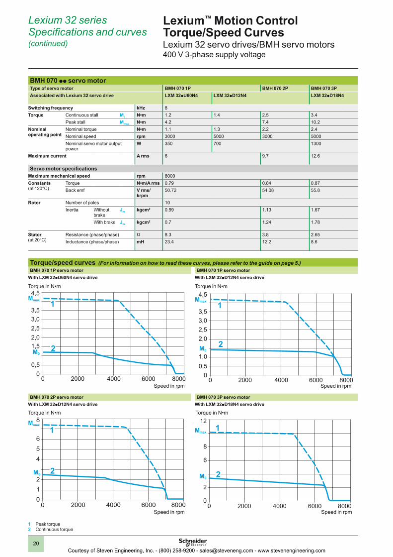
Lexium™ Motion Control Torque/Speed CurvesLexium 32 servo drives/BMH servo motors400 V 3-phase supply voltage
BMH 070 pp servo motorType of servo motor BMH 070 1P BMH 070 2P BMH 070 3PAssociated with Lexium 32 servo drive LXM 32pU60N4 LXM 32pD12N4 LXM 32pD18N4
Switching frequency kHz 8Torque Continuous stall M0 N•m 1.2 1.4 2.5 3.4
Peak stall Mmax N•m 4.2 7.4 10.2Nominal operating point
Nominal torque N•m 1.1 1.3 2.2 2.4Nominal speed rpm 3000 5000 3000 5000Nominal servo motor output power
W 350 700 1300
Maximum current A rms 6 9.7 12.6
Servo motor specificationsMaximum mechanical speed rpm 8000Constants(at 120°C)
Torque N•m/A rms 0.79 0.84 0.87Back emf V rms/
krpm50.72 54.08 55.8
Rotor Number of poles 10Inertia Without
brakeJm kgcm2 0.59 1.13 1.67
With brake Jm kgcm2 0.7 1.24 1.78
Stator(at 20°C)
Resistance (phase/phase) W 8.3 3.8 2.65Inductance (phase/phase) mH 23.4 12.2 8.6
Torque/speed curves (For information on how to read these curves, please refer to the guide on page 5.)BMH 070 1P servo motor BMH 070 1P servo motor
With LXM 32pU60N4 servo drive With LXM 32pD12N4 servo drive
BMH 070 2P servo motor BMH 070 3P servo motor With LXM 32pD12N4 servo drive With LXM 32pD18N4 servo drive
1 Peak torque2 Continuous torque
Torque in N•m
Speed in rpm
Torque in N•m
Speed in rpm
Torque in N•m
Speed in rpm
Torque in N•m
Speed in rpm
4000 6000 800000
2000
0,5
1,52,0
3,02,5
3,5
4,5Mmax
M0
1
2
4000 6000 800000
2000
0,51,0
2,0
3,02,5
3,5
4,5Mmax
M0
1
2
Mmax
M0
0 2000 4000 6000 800001
4
2
65
8
2
1 Mmax
M0
1
00
2
8
6
12
2
2000 4000 6000 8000
Courtesy of Steven Engineering, Inc. - (800) 258-9200 - [email protected] - www.stevenengineering.com

21
Lexium 32 seriesSpecifications and curves(continued)
Lexium™ Motion Control Torque/Speed CurvesLexium 32 servo drives/BMH servo motors400 V 3-phase supply voltage
BMH 100 pp servo motorType of servo motor BMH 100 1P BMH 100 2P BMH 100 3PAssociated with Lexium 32 servo drive LXM 32pD12N4 LXM 32pD18N4 LXM 32pD30N4
Switching frequency kHz 8Torque Continuous stall M0 N•m 3.3 3.4 5.2 8.4
Peak stall Mmax N•m 10.8 18.4 25.1Nominal operating point
Nominal torque N•m 1.9 3.1 3.9 5.2Nominal speed rpm 4000 4000 5000Nominal servo motor output power
W 800 1300 1600 2700
Maximum current A rms 11.9 18 29.1
Servo motor specificationsMaximum mechanical speed rpm 6000Constants(at 120°C)
Torque N•m/A rms 1.1 1.2 1Back emf V rms/
krpm70.3 77 63.5
Rotor Number of poles 10Inertia Without
brakeJm kgcm2 3.2 6.3 9.4
With brake Jm kgcm2 3.68 6.77 10.3
Stator(at 20°C)
Resistance (phase/phase) W 3.1 1.51 0.63Inductance (phase/phase) mH 13.9 7.5 4
Torque/speed curves (For information on how to read these curves, please refer to the guide on page 5.)BMH 100 1P servo motor BMH 100 1P servo motor
With LXM 32pD12N4 servo drive With LXM 32pD18N4 servo drive
BMH 100 2P servo motor BMH 100 3P servo motor With LXM 32pD18N4 servo drive With LXM 32pD30N4 servo drive
1 Peak torque2 Continuous torque
Torque in N•m
Speed in rpm
Torque in N•m
Speed in rpm
Torque in N•m
Speed in rpm
Torque in N•m
Speed in rpm
Mmax
M0
1
0 2000 4000 60000
2
8
6
12
10
2
Mmax
M0
0 2000 4000 60000
2
8
6
12
2
1
Mmax
M0
0 2000 4000 6000024
8
1210
1614
20
1
2
Mmax
M0
1
0 2000 4000 60000
5
20
15
30
2
Courtesy of Steven Engineering, Inc. - (800) 258-9200 - [email protected] - www.stevenengineering.com

22
Lexium 32 seriesSpecifications and curves(continued)
Lexium™ Motion Control Torque/Speed CurvesLexium 32 servo drives/BMH servo motors400 V 3-phase supply voltage
BMH 140 pp servo motorType of servo motor BMH 140 1P BMH 140 2P BMH 140 3PAssociated with Lexium 32 servo drive LXM32pD30N4 LXM 32pD72N4
Switching frequency kHz 8Torque Continuous stall M0 N•m 10.3 18.5 24
Peak stall Mmax N•m 30.8 55.3 75Nominal operating point
Nominal torque N•m 7.7 11.2 14.9Nominal speed rpm 3000Nominal servo motor output power
W 2400 3500 4700
Maximum current A rms 29.8 57.4 62.3
Servo motor specificationsMaximum mechanical speed rpm 4000Constants(at 120°C)
Torque N•m/A rms 1.2 1.1 1.34Back emf V rms/
krpm77.4 70.7 85.9
Rotor Number of poles 10Inertia Without
brakeJm kgcm2 16.5 32 47.5
With brake Jm kgcm2 17.96 33.5 50.27
Stator(at 20°C)
Resistance (phase/phase) W 0.69 0.23 0.22Inductance (phase/phase) mH 6.7 3
Torque/speed curves (For information on how to read these curves, please refer to the guide on page 5.)BMH 140 1P servo motor BMH 140 2P servo motor
With LXM 32pD30N4 servo drive With LXM 32pD72N4 servo drive
BMH 140 3P servo motor With LXM 32pD72N4 servo drive
1 Peak torque2 Continuous torque
Torque in N•m
Speed in rpm
Torque in N•m
Speed in rpm
Torque in N•m
Speed in rpm
Mmax
M0
0 1000 2000 3000 40000
5
20
15
25
35 1
2
Mmax
M0
0 1000 2000 3000 40000
10
40
30
60
50 1
2
1000 2000 3000 4000
Mmax
M0
0010
40
20
6050
80
2
1
Courtesy of Steven Engineering, Inc. - (800) 258-9200 - [email protected] - www.stevenengineering.com

23
BMH 190 pp servo motorType of servo motor BMH 190 1P BMH 190 2P BMH 190 3PAssociated with Lexium 32 servo drive LXM 32p
D72N4Switching frequency kHz 8Torque Continuous stall M0 N•m 30 37.4 43.2
Peak stall Mmax N•m 77.7 101 123Nominal operating point
Nominal torque N•m 18.4 22.3 36Nominal speed rpm 2500 2500 1500Nominal servo motor output power
W 4800 5900 5700
Maximum current A rms 24
Servo motor specificationsMaximum mechanical speed rpm 4000 4000 3500Constants(at 120°C)
Torque N•m/A rms 1.3 1.56 1.8Back emf V rms/
krpm87.6 108.3 129.2
Rotor Number of poles 10Inertia Without
brakeJm kgcm2 67.7 130.1 194.1
With brake Jm kgcm2 71.8 144.8 208.8
Stator(at 20°C)
Resistance (phase/phase) W 0.24 0.15 0.13Inductance (phase/phase) mH 5.08 3.86 3.62
Torque/speed curves (For information on how to read these curves, please refer to the guide on page 5.)BMH 190 1P servo motor BMH 190 2P servo motor
With LXM 32pD72N4 servo drive With LXM 32pD72N4 servo drive
BMH 190 3P servo motor With LXM 32pD72N4 servo drive
1 Peak torque2 Continuous torque
Lexium 32 seriesSpecifications and curves(continued)
Lexium™ Motion Control Torque/Speed CurvesLexium 32 servo drives/BMH servo motors400 V 3-phase supply voltage
Torq
ue in
N•m
Spe
ed in
rpm
0 1000 2000 3000 40000
10
20
40
50
70
80
90
100
60
2
Mmax
M0
1
Torq
ue in
N•m
Spe
ed in
rpm
0 1000 2000 3000 40000
20
40
60
80
120
140
160
2
Mmax
M0
1
Torq
ue in
N•m
Spe
ed in
rpm
0 1000 2000 3000 35000
50
100
200
150
250
2
Mmax
M0
1
Courtesy of Steven Engineering, Inc. - (800) 258-9200 - [email protected] - www.stevenengineering.com

24
BMH 190 pp servo motorType of servo motor BMH 190 1P BMH 190 2P BMH 190 3PAssociated with Lexium 32 servo drive LXM 32p
MD85N4Switching frequency kHz 8Torque Continuous stall M0 N•m 30 48 57.6
Peak stall Mmax N•m 86.6 115.5 141.3Nominal operating point
Nominal torque N•m 16.5 29 35Nominal speed rpm 3000 2000 2000Nominal servo motor output power
W 5180 6070 7330
Maximum current A rms 32
Servo motor specificationsMaximum mechanical speed rpm 4000 4000 3500Constants(at 120°C)
Torque N•m/A rms 1.3 1.56 1.8Back emf V rms/
krpm87.6 108.3 129.2
Rotor Number of poles 10Inertia Without
brakeJm kgcm2 67.7 130.1 194.1
With brake Jm kgcm2 71.8 144.8 208.8
Stator(at 20°C)
Resistance (phase/phase) W 0.24 0.15 0.13Inductance (phase/phase) mH 5.08 3.86 3.62
Torque/speed curves (For information on how to read these curves, please refer to the guide on page 5.)BMH 190 1P servo motor BMH 190 2P servo motor
With LXM 32pMD85N4 servo drive With LXM 32pMD85N4 servo drive
BMH 190 3P servo motor With LXM 32pMD85N4 servo drive
1 Peak torque2 Continuous torque
Lexium 32 seriesSpecifications and curves(continued)
Lexium™ Motion Control Torque/Speed CurvesLexium 32 servo drives/BMH servo motors400 V 3-phase supply voltage
Torq
ue in
N•m
Spe
ed in
rpm
0 1000 2000 3000 40000
10
20
30
50
70
80
90
100
60
2
Mmax
M0
1
Torq
ue in
N•m
Spe
ed in
rpm
0 1000 2000 3000 40000
20
40
60
80
100
140
160
120
2
Mmax
M0
1
Torq
ue in
N•m
Spe
ed in
rpm
0 1000 2000 3000 35000
50
100
250
200
2
Mmax
M0
1
Courtesy of Steven Engineering, Inc. - (800) 258-9200 - [email protected] - www.stevenengineering.com

25
BMH 190 pp servo motorType of servo motor BMH 190 1P BMH 190 2P BMH 190 3PAssociated with Lexium 32 servo drive LXM 32p
MC10N4Switching frequency kHz 8Torque Continuous stall M0 N•m 30 48 65
Peak stall Mmax N•m 89.7 130.7 162.7Nominal operating point
Nominal torque N•m 16.5 29 37Nominal speed rpm 3000 2000 2000Nominal servo motor output power
W 5180 6070 7750
Maximum current A rms 40
Servo motor specificationsMaximum mechanical speed rpm 4000 4000 3500Constants(at 120°C)
Torque N•m/A rms 1.3 1.56 1.8Back emf V rms/
krpm87.6 108.3 129.2
Rotor Number of poles 10Inertia Without
brakeJm kgcm2 67.7 130.1 194.1
With brake Jm kgcm2 71.8 144.8 208.8
Stator(at 20°C)
Resistance (phase/phase) W 0.24 0.15 0.13Inductance (phase/phase) mH 5.08 3.86 3.62
Torque/speed curves (For information on how to read these curves, please refer to the guide on page 5.)BMH 190 1P servo motor BMH 190 2P servo motor
With LXM 32pMC10N4 servo drive With LXM 32pMC10N4 servo drive
BMH 190 3P servo motor With LXM 32pMC10N4 servo drive
1 Peak torque2 Continuous torque
Lexium 32 seriesSpecifications and curves(continued)
Lexium™ Motion Control Torque/Speed CurvesLexium 32 servo drives/BMH servo motors400 V 3-phase supply voltage
Torq
ue in
N•m
Spe
ed in
rpm
0 1000 2000 3000 40000
10
20
30
40
70
80
100
60
2
Mmax
M0
1
Torq
ue in
N•m
Spe
ed in
rpm
0 1000 2000 3000 40000
20
40
80
120
100
140
160
2
Mmax
M0
1
Torq
ue in
N•m
Spe
ed in
rpm
0 1000 2000 3000 35000
50
100
200
150
250
2
Mmax
M0
1
Courtesy of Steven Engineering, Inc. - (800) 258-9200 - [email protected] - www.stevenengineering.com

26
Lexium 32 seriesSpecifications and curves(continued)
Lexium™ Motion Control Torque/Speed CurvesLexium 32 servo drives/BMH servo motors400 V 3-phase supply voltage
BMH 205 pp servo motorType of servo motor BMH 205 1P BMH 205 2P BMH 205 3PAssociated with Lexium 32 servo drive LXM 32pD72N4
Switching frequency kHz 8Torque Continuous stall M0 N•m 34.4 62.5 84
Peak stall Mmax N•m 103.4 170 232Nominal operating point
Nominal torque N•m 25.8 41.6 52.2Nominal speed rpm 2000 1500 1200Nominal servo motor output power
W 5400 6500
Maximum current A rms 72
Servo motor specificationsMaximum mechanical speed rpm 3800Constants(at 120°C)
Torque N•m/A rms 1.6 2.6 3.5Back emf V rms/
krpm104 161 218
Rotor Number of poles 10Inertia Without
brakeJm kgcm2 71.4 129 190
With brake Jm kgcm2 87.4 145 206
Stator(at 20°C)
Resistance (phase/phase) W 0.3 0.3 0.32Inductance (phase/phase) mH 5.9 5.6 6.9
Torque/speed curves (For information on how to read these curves, please refer to the guide on page 5.)BMH 205 1P servo motor BMH 205 2P servo motor
With LXM 32pD72N4 servo drive With LXM 32pD72N4 servo drive
BMH 205 3P servo motor With LXM 32pD72N4 servo drive
1 Peak torque2 Continuous torque
Torque in N•m
Speed in rpm
Torque in N•m
Speed in rpm
Mmax
M0
0 1000 2000 3000 40000
20
40
80
60
1201
2
Mmax
M0
0 1000 2000 300002040
80
120100
140
180
2
1
Torque in N•m
Speed in rpm
M0
1
0
50
100
150
200
250
2
Mmax
0 1000 2000 3000
Courtesy of Steven Engineering, Inc. - (800) 258-9200 - [email protected] - www.stevenengineering.com

27
Lexium 32 seriesSpecifications and curves(continued)
Lexium™ Motion Control Torque/Speed CurvesLexium 32 servo drives/BMH servo motors480 V 3-phase supply voltage
BMH 070 pp servo motorType of servo motor BMH 070 1P BMH 070 2P BMH 070 3PAssociated with Lexium 32 servo drive LXM 32pU60N4 LXM 32pD12N4 LXM 32pD18N4
Switching frequency kHz 8
Torque/speed curves (For information on how to read these curves, please refer to the guide on page 5.)BMH 070 1P servo motor BMH 070 1P servo motor
With LXM 32pU60N4 servo drive With LXM 32pD12N4 servo drive
BMH 070 2P servo motor BMH 070 3P servo motor With LXM 32pD12N4 servo drive With LXM 32pD18N4 servo drive
1 Peak torque2 Continuous torque
Torque in N•m
Speed in rpm
Torque in N•m
Speed in rpm
Torque in N•m
Speed in rpm
Torque in N•m
Speed in rpm
Torque Continuous stall M0 N•m 1.2 1.4 2.5 3.4Peak stall Mmax N•m 4.2 7.4 10.2
Nominal operating point
Nominal torque N•m 1.1 1.3 2.2 2.4Nominal speed rpm 3000 5000 3000 5000Nominal servo motor output power
W 350 700 1300
Maximum current A rms 6 9.7 12.6
Servo motor specificationsMaximum mechanical speed rpm 8000Constants(at 120°C)
Torque N•m/A rms 0.79 0.84 0.87Back emf V rms/
krpm50.72 54.08 55.8
Rotor Number of poles 10Inertia Without
brakeJm kgcm2 0.59 1.13 1.67
With brake Jm kgcm2 0.7 1.24 1.78
Stator(at 20°C)
Resistance (phase/phase) W 8.3 3.8 2.65Inductance (phase/phase) mH 23.4 12.2 8.6
Mmax
M0
4000 6000 800000
2000
0,5
1,52,0
3,02,5
3,5
4,51
2
4000 6000 800000
2000
0,51,0
2,0
3,02,5
3,5
4,5Mmax
M0
1
2
Mmax
M0
0 2000 4000 6000 8000012
4
65
8
2
1 Mmax
M0
1
00
2
8
6
4
12
2
2000 4000 6000 8000
Courtesy of Steven Engineering, Inc. - (800) 258-9200 - [email protected] - www.stevenengineering.com

28
Lexium 32 seriesSpecifications and curves(continued)
Lexium™ Motion Control Torque/Speed CurvesLexium 32 servo drives/BMH servo motors480 V 3-phase supply voltage
BMH 100 pp servo motorType of servo motor BMH 100 1P BMH 100 2P BMH 100 3PAssociated with Lexium 32 servo drive LXM 32p
D12N4LXM 32p D18N4
LXM 32p D30N4
Switching frequency kHz 8Torque Continuous stall M0 N•m 3.3 3.4 6.2 8.4
Peak stall Mmax N•m 10.8 18.4 25.1Nominal operating point
Nominal torque N•m 1.9 3.1 3.9 5.2Nominal speed rpm 4000 5000Nominal servo motor output power
W 800 1300 1600 2700
Maximum current A rms 11.9 18 29.1
Servo motor specificationsMaximum mechanical speed rpm 6000Constants(at 120°C)
Torque N•m/A rms 1.1 1.2 1Back emf V rms/
krpm70.3 77 63.5
Rotor Number of poles 10Inertia Without
brakeJm kgcm2 3.2 6.3 9.4
With brake Jm kgcm2 3.68 6.77 10.3
Stator(at 20°C)
Resistance (phase/phase) W 3.1 1.51 0.63Inductance (phase/phase) mH 13.9 7.5 4
Torque/speed curves (For information on how to read these curves, please refer to the guide on page 5.)BMH 100 1P servo motor BMH 100 1P servo motor
With LXM 32pD12N4 servo drive With LXM 32pD18N4 servo drive
BMH 100 2P servo motor BMH 100 3P servo motor With LXM 32pD18N4 servo drive With LXM 32pD30N4 servo drive
1 Peak torque2 Continuous torque
Torque in N•m
Speed in rpm
Torque in N•m
Speed in rpm
Torque in N•m
Speed in rpm
Torque in N•m
Speed in rpm
Mmax
M0
1
0 2000 4000 60000
2
8
6
4
12
10
2
Mmax
M0
1
0 2000 4000 60000
2
8
6
4
12
2
Mmax
M0
0 2000 4000 6000024
8
1210
1614
20
2
1 Mmax
M0
1
0 2000 4000 60000
5
20
15
10
30
2
Courtesy of Steven Engineering, Inc. - (800) 258-9200 - [email protected] - www.stevenengineering.com

29
Lexium 32 seriesSpecifications and curves(continued)
Lexium™ Motion Control Torque/Speed CurvesLexium 32 servo drives/BMH servo motors480 V 3-phase supply voltage
BMH 140 pp servo motorType of servo motor BMH 140 1P BMH 140 2P BMH 140 3PAssociated with Lexium 32 servo drive LXM 32p
D30N4LXM 32p D72N4
Switching frequency kHz 8Torque Continuous stall M0 N•m 10.3 18.5 24
Peak stall Mmax N•m 30.8 55.3 75Nominal operating point
Nominal torque N•m 7.7 11.2 14.9Nominal speed rpm 3000Nominal servo motor output power
W 2400 3500 4700
Maximum current A rms 29.8 57.4 62.3
Servo motor specificationsMaximum mechanical speed rpm 4000Constants(at 120°C)
Torque N•m/A rms 1.2 1.1 1.34Back emf V rms/
krpm77.4 70.7 85.9
Rotor Number of poles 10Inertia Without
brakeJm kgcm2 16.5 32 47.5
With brake Jm kgcm2 17.96 33.5 50.27
Stator(at 20°C)
Resistance (phase/phase) W 0.69 0.23 0.22Inductance (phase/phase) mH 6.7 3
Torque/speed curves (For information on how to read these curves, please refer to the guide on page 5.)BMH 140 1P servo motor BMH 140 2P servo motor
With LXM 32pD30N4 servo drive With LXM 32pD72N4 servo drive
BMH 140 3P servo motor With LXM 32pD72N4 servo drive
1 Peak torque2 Continuous torque
Torque in N•m
Speed in rpm
Torque in N•m
Speed in rpm
Torque in N•m
Speed in rpm
Mmax
M0
0 1000 2000 3000 40000
5
20
15
25
35 1
2
Mmax
M0
0 1000 2000 3000 40000
10
40
30
60
50 1
2
1000 2000 3000 4000
Mmax
M0
0010
40
20
6050
80
2
1
Courtesy of Steven Engineering, Inc. - (800) 258-9200 - [email protected] - www.stevenengineering.com

30
Lexium™ Motion Control Torque/Speed CurvesLexium 32 servo drives/BMH servo motors480 V 3-phase supply voltage
Lexium 32 seriesSpecifications and curves(continued)
BMH 190 pp servo motorType of servo motor BMH 190 1P BMH 190 2P BMH 190 3PAssociated with Lexium 32 servo drive LXM 32p
D72N4Switching frequency kHz 8Torque Continuous stall M0 N•m 30 37.4 43.2
Peak stall Mmax N•m 77.7 101 123Nominal operating point
Nominal torque N•m 18.4 22.3 36Nominal speed rpm 2500 2500 1500Nominal servo motor output power
W 4800 5900 5700
Maximum current A rms 24
Servo motor specificationsMaximum mechanical speed rpm 4000 4000 3500Constants(at 120°C)
Torque N•m/A rms 1.3 1.56 1.8Back emf V rms/
krpm87.6 108.3 129.2
Rotor Number of poles 10Inertia Without
brakeJm kgcm2 67.7 130.1 194.1
With brake Jm kgcm2 71.8 144.8 208.8
Stator(at 20°C)
Resistance (phase/phase) W 0.24 0.15 0.13Inductance (phase/phase) mH 5.08 3.86 3.62
Torque/speed curves (For information on how to read these curves, please refer to the guide on page 5.)BMH 190 1P servo motor BMH 190 2P servo motor
With LXM 32pD72N4 servo drive With LXM 32pD72N4 servo drive
BMH 190 3P servo motor With LXM 32pD72N4 servo drive
1 Peak torque2 Continuous torque
Torq
ue in
N•m
Spe
ed in
rpm
0 1000 2000 3000 40000
10
20
50
40
70
80
90
100
60
2
Mmax
M0
1
Torq
ue in
N•m
Spe
ed in
rpm
0 1000 2000 3000 40000
20
60
80
120
140
160
2
Mmax
M0
1
Torq
ue in
N•m
Spe
ed in
rpm
0 1000 2000 3000 35000
50
100
200
150
250
2
Mmax
M0
1
Courtesy of Steven Engineering, Inc. - (800) 258-9200 - [email protected] - www.stevenengineering.com

31
Lexium™ Motion Control Torque/Speed CurvesLexium 32 servo drives/BMH servo motors480 V 3-phase supply voltage
Lexium 32 seriesSpecifications and curves(continued)
BMH 190 pp servo motorType of servo motor BMH 190 1P BMH 190 2P BMH 190 3PAssociated with Lexium 32 servo drive LXM 32p
MD85N4Switching frequency kHz 8Torque Continuous stall M0 N•m 30 48 57.6
Peak stall Mmax N•m 86.6 115.5 141.3Nominal operating point
Nominal torque N•m 16.5 29 35Nominal speed rpm 3000 2000 2000Nominal servo motor output power
W 5180 6070 7330
Maximum current A rms 32
Servo motor specificationsMaximum mechanical speed rpm 4000 4000 3500Constants(at 120°C)
Torque N•m/A rms 1.3 1.56 1.8Back emf V rms/
krpm87.6 108.3 129.2
Rotor Number of poles 10Inertia Without
brakeJm kgcm2 67.7 130.1 194.1
With brake Jm kgcm2 71.8 144.8 208.8
Stator(at 20°C)
Resistance (phase/phase) W 0.24 0.15 0.13Inductance (phase/phase) mH 5.08 3.86 3.62
Torque/speed curves (For information on how to read these curves, please refer to the guide on page 5.)BMH 190 1P servo motor BMH 190 2P servo motor
With LXM 32pMD85N4 servo drive With LXM 32pMD85N4 servo drive
BMH 190 3P servo motor With LXM 32pMD85N4 servo drive
1 Peak torque2 Continuous torque
Torq
ue in
N•m
Spe
ed in
rpm
0 1000 2000 3000 40000
10
20
30
50
70
80
100
60
2
Mmax
M0
1
Torq
ue in
N•m
Spe
ed in
rpm
0 1000 2000 3000 40000
20
40
60
80
120
100
140
160
2
Mmax
M0
1
Torq
ue in
N•m
Spe
ed in
rpm
0 1000 2000 3000 35000
50
100
200
150
250
2
Mmax
M0
1
Courtesy of Steven Engineering, Inc. - (800) 258-9200 - [email protected] - www.stevenengineering.com

32
Lexium™ Motion Control Torque/Speed CurvesLexium 32 servo drives/BMH servo motors480 V 3-phase supply voltage
Lexium 32 seriesSpecifications and curves(continued)
BMH 190 pp servo motorType of servo motor BMH 190 1P BMH 190 2P BMH 190 3PAssociated with Lexium 32 servo drive LXM 32p
MC10N4Switching frequency kHz 8Torque Continuous stall M0 N•m 30 48 65
Peak stall Mmax N•m 89.7 130.7 162.7Nominal operating point
Nominal torque N•m 16.5 29 37Nominal speed rpm 3000 2000 2000Nominal servo motor output power
W 5180 6070 7750
Maximum current A rms 40
Servo motor specificationsMaximum mechanical speed rpm 4000 4000 3500Constants(at 120°C)
Torque N•m/A rms 1.3 1.56 1.8Back emf V rms/
krpm87.6 108.3 129.2
Rotor Number of poles 10Inertia Without
brakeJm kgcm2 67.7 130.1 194.1
With brake Jm kgcm2 71.8 144.8 208.8
Stator(at 20°C)
Resistance (phase/phase) W 0.24 0.15 0.13Inductance (phase/phase) mH 5.08 3.86 3.62
Torque/speed curves (For information on how to read these curves, please refer to the guide on page 5.)BMH 190 1P servo motor BMH 190 2P servo motor
With LXM 32pMC10N4 servo drive With LXM 32pMC10N4 servo drive
BMH 190 3P servo motor With LXM 32pMC10N4 servo drive
1 Peak torque2 Continuous torque
Torq
ue in
N•m
Spe
ed in
rpm
0 1000 2000 3000 40000
10
20
30
40
70
80
100
60
2
Mmax
M0
1
Torq
ue in
N•m
Spe
ed in
rpm
0 1000 2000 3000 40000
20
40
80
120
100
140
160
2
Mmax
M0
1
Torq
ue in
N•m
Spe
ed in
rpm
0 1000 2000 3000 35000
50
100
200
150
250
2
Mmax
M0
1
Courtesy of Steven Engineering, Inc. - (800) 258-9200 - [email protected] - www.stevenengineering.com

33
Lexium 32 seriesSpecifications and curves(continued)
Lexium™ Motion Control Torque/Speed CurvesLexium 32 servo drives/BMH servo motors480 V 3-phase supply voltage
BMH 205 pp servo motorType of servo motor BMH 205 1P BMH 205 2P BMH 205 3PAssociated with Lexium 32 servo drive LXM 32p
D72N4Switching frequency kHz 8Torque Continuous stall M0 N•m 34.4 62.5 84
Peak stall Mmax N•m 103.4 170 232Nominal operating point
Nominal torque N•m 25.8 41.6 52.2Nominal speed rpm 2000 1500 1200Nominal servo motor output power
W 5400 6500
Maximum current A rms 72
Servo motor specificationsMaximum mechanical speed rpm 3800Constants(at 120°C)
Torque N•m/A rms 1.6 2.6 3.5Back emf V rms/
krpm104 161 218
Rotor Number of poles 10Inertia Without
brakeJm kgcm2 71.4 129 190
With brake Jm kgcm2 87.4 145 206
Stator(at 20°C)
Resistance (phase/phase) W 0.3 0.32Inductance (phase/phase) mH 5.9 5.6 6.9
Torque/speed curves (For information on how to read these curves, please refer to the guide on page 5.)BMH 205 1P servo motor BMH 205 2P servo motor
With LXM 32pD72N4 servo drive With LXM 32pD72N4 servo drive
BMH 205 3P servo motor With LXM 32pD72N4 servo drive
1 Peak torque2 Continuous torque
Torque in N•m
Speed in rpm
Torque in N•m
Speed in rpm
Torque in N•m
Speed in rpm
Mmax
M0
0 1000 2000 3000 40000
20
80
60
1201
2
Mmax
M0
0 1000 2000 300002040
80
120100
140
180
1
2
M0
1
0
50
100
150
200
250
2
Mmax
0 1000 2000 3000
Courtesy of Steven Engineering, Inc. - (800) 258-9200 - [email protected] - www.stevenengineering.com

34
Lexium 32 seriesSpecifications and curves(continued)
Lexium™ Motion Control Torque/Speed CurvesLexium 32 servo drives/BSH servo motors115 V single-phase supply voltage
BSH 055 pp servo motorType of servo motor BSH 055 1T BSH 055 2T BSH 055 3TAssociated with Lexium 32 servo drive LXM 32p
U90M2LXM 32p D18M2
Switching frequency kHz 8Torque Continuous stall M0 N•m 0.5 0.8 1.2
Peak stall Mmax N•m 1.5 1.9 3.3Nominal operating point
Nominal torque N•m 0.49 0.77 1.14Nominal speed rpm 3000Nominal servo motor output power
W 150 250 350
Maximum current A rms 5.4 6 10
Servo motor specificationsMaximum mechanical speed rpm 9000Constants(at 120°C)
Torque N•m/A rms 0.36 0.39Back emf V rms/
krpm22
Rotor Number of poles 6Inertia Without
brakeJm kgcm2 0.059 0.096 0.134
With brake Jm kgcm2 0.0803 0.1173 0.1553Stator(at 20°C)
Resistance (phase/phase) W 12.2 5.2 3.1Inductance (phase/phase) mH 20.8 10.6 7.4
Torque/speed curves (For information on how to read these curves, please refer to the guide on page 5.)BSH 055 1T servo motor BSH 055 2T servo motor
With LXM 32pU90M2 servo drive With LXM 32pU90M2 servo drive
BSH 055 3T servo motor With LXM 32pD18M2 servo drive
1 Peak torque2 Continuous torque
Torque in N•m
Speed in rpm
Torque in N•m
Speed in rpm
Mmax
M0
0 1000 2000 3000 4000 50000
0,2
0,60,8
1,21,4
1,0
1,6
1
2 M0
Mmax
0 1000 2000 3000 4000 50000
0,5
1,0
1,5
2,5
2
1
Mmax
M01,0
0 1000 2000 3000 4000 50000
0,5
2,0
1,5
3,0
2,5
3,5
1
2
Torque in N•m
Speed in rpm
Courtesy of Steven Engineering, Inc. - (800) 258-9200 - [email protected] - www.stevenengineering.com

35
Lexium 32 seriesSpecifications and curves(continued)
Lexium™ Motion Control Torque/Speed CurvesLexium 32 servo drives/BSH servo motors115 V single-phase supply voltage
BSH 070/100 pp servo motorType of servo motor BSH 070 1T BSH 070 2T BSH 100 1TAssociated with Lexium 32 servo drive LXM 32p
D18M2LXM 32p D30M2
Switching frequency kHz 8Torque Continuous stall M0 N•m 1.4 2.2 3.3
Peak stall Mmax N•m 3.5 6.1 6.3Nominal operating point
Nominal torque N•m 1.36 2.07 2.75Nominal speed rpm 2500Nominal servo motor output power
W 350 550 700
Maximum current A rms 10 15 15
Servo motor specificationsMaximum mechanical speed rpm 8000 6000Constants(at 120°C)
Torque N•m/A rms 0.44 0.45Back emf V rms/
krpm26 28 29
Rotor Number of poles 6 8Inertia Without
brakeJm kgcm2 0.25 0.41 1.4
With brake Jm kgcm2 0.322 0.482 2.018Stator(at 20°C)
Resistance (phase/phase) W 3.3 1.5 0.87Inductance (phase/phase) mH 12.3 6.7 4
Torque/speed curves (For information on how to read these curves, please refer to the guide on page 5.)BSH 070 1T servo motor BSH 070 2T servo motor
With LXM 32pD18M2 servo drive With LXM 32pD30M2 servo drive
BSH 100 1T servo motor With LXM 32pD30M2 servo drive
1 Peak torque2 Continuous torque
Torque in N•m
Speed in rpm
Torque in N•m
Speed in rpm
Torque in N•m
Speed in rpm
Mmax
M0
1
0 1000 2000 3000 4000 50000
0,5
1,0
2,0
3,0
2,5
4,0
2
Mmax
M0
1
0 1000 2000 3000 40000
1
4
3
5
7
2
Mmax
M0
0 1000 2000 3000 40000
1
2
4
5
7
1
2
Courtesy of Steven Engineering, Inc. - (800) 258-9200 - [email protected] - www.stevenengineering.com

36
Lexium 32 seriesSpecifications and curves(continued)
Lexium™ Motion Control Torque/Speed CurvesLexium 32 servo drives/BSH servo motors230 V single-phase supply voltage
BSH 055 pp servo motorType of servo motor BSH 055 1T BSH 055 2T BSH 055 3TAssociated with Lexium 32 servo drive LXM 32p
U45M2LXM 32p U90M2
Switching frequency kHz 8Torque Continuous stall M0 N•m 0.5 0.8 1.2
Peak stall Mmax N•m 1.4 2.5 3Nominal operating point
Nominal torque N•m 0.45 0.74 0.84Nominal speed rpm 6000Nominal servo motor output power
W 300 450 550
Maximum current A rms 4.5 8.8 9
Servo motor specificationsMaximum mechanical speed rpm 9000Constants(at 120°C)
Torque N•m/A rms 0.36 0.39Back emf V rms/
krpm22
Rotor Number of poles 6Inertia Without
brakeJm kgcm2 0.059 0.096 0.134
With brake Jm kgcm2 0.0803 0.1173 0.1553Stator(at 20°C)
Resistance (phase/phase) W 12.2 5.2 3.1Inductance (phase/phase) mH 20.8 10.6 7.4
Torque/speed curves (For information on how to read these curves, please refer to the guide on page 5.)BSH 055 1T servo motor BSH 055 2T servo motor
With LXM 32pU45M2 servo drive With LXM 32pU90M2 servo drive
BSH 055 3T servo motor With LXM 32pU90M2 servo drive
1 Peak torque2 Continuous torque
Torque in N•m
Speed in rpm
Torque in N•m
Speed in rpm
Torque in N•m
Speed in rpm
Mmax
M0
0,20,4
0,60,8
1,21,0
1,6
0 30001000 5000 7000 90000
1
2
Mmax
M0
0 30001000 5000 7000 90000
0,5
2,0
1,5
3,01
2
Mmax
M0
0 30001000 5000 7000 90000
0,5
1,0
2,0
2,5
3.5 1
2
Courtesy of Steven Engineering, Inc. - (800) 258-9200 - [email protected] - www.stevenengineering.com

37
Lexium 32 seriesSpecifications and curves(continued)
Lexium™ Motion Control Torque/Speed CurvesLexium 32 servo drives/BSH servo motors230 V single-phase supply voltage
BSH 070 pp servo motorType of servo motor BSH 070 1T BSH 070 2T BSH 070 3TAssociated with Lexium 32 servo drive LXM 32p
U90M2LXM 32p D18M2
Switching frequency kHz 8Torque Continuous stall M0 N•m 1.3 2.2 2.6
Peak stall Mmax N•m 3.5 7.2 7.4Nominal operating point
Nominal torque N•m 0.94 1.8 2.1Nominal speed rpm 5000 4000Nominal servo motor output power
W 500 950 900
Maximum current A rms 9 18
Servo motor specificationsMaximum mechanical speed rpm 8000Constants(at 120°C)
Torque N•m/A rms 0.44 0.45 0.44Back emf V rms/
krpm26 28 29
Rotor Number of poles 6Inertia Without
brakeJm kgcm2 0.25 0.41 0.58
With brake Jm kgcm2 0.322 0.482 0.81Stator(at 20°C)
Resistance (phase/phase) W 3.3 1.5 0.91Inductance (phase/phase) mH 12.3 6.7 4.4
Torque/speed curves (For information on how to read these curves, please refer to the guide on page 5.)BSH 070 1T servo motor BSH 070 2T servo motor
With LXM 32pU90M2 servo drive With LXM 32pD18M2 servo drive
BSH 070 3T servo motor With LXM 32pD18M2 servo drive
1 Peak torque2 Continuous torque
Torque in N•m
Speed in rpm
Torque in N•m
Speed in rpm
Torque in N•m
Speed in rpm
Mmax
M0
1
0 2000 4000 6000 80000
0,5
1,0
2,0
3,0
2,5
4,0
2
Mmax
M0
1
0 2000 4000 6000 800001
43
65
8
2
Mmax
M0
0 2000 4000 6000 800001
2
4
65
87
2
1
Courtesy of Steven Engineering, Inc. - (800) 258-9200 - [email protected] - www.stevenengineering.com

38
Lexium 32 seriesSpecifications and curves(continued)
Lexium™ Motion Control Torque/Speed CurvesLexium 32 servo drives/BSH servo motors230 V single-phase supply voltage
BSH 100 pp servo motorType of servo motor BSH 100 1T BSH 100 2TAssociated with Lexium 32 servo drive LXM 32p
D18M2LXM 32p D30M2
Switching frequency kHz 8Torque Continuous stall M0 N•m 2.7 5.8
Peak stall Mmax N•m 7.5 16.4Nominal operating point
Nominal torque N•m 2.2 3.7Nominal speed rpm 4000Nominal servo motor output power
W 900 1500
Maximum current A rms 18 30
Servo motor specificationsMaximum mechanical speed rpm 6000Constants(at 120°C)
Torque N•m/A rms 0.45 0.59Back emf V rms/
krpm29 37
Rotor Number of poles 8Inertia Without
brakeJm kgcm2 1.4 2.31
With brake Jm kgcm2 2.018 2.928Stator(at 20°C)
Resistance (phase/phase) W 0.87 0.56Inductance (phase/phase) mH 4 3
Torque/speed curves (For information on how to read these curves, please refer to the guide on page 5.)BSH 100 1T servo motor BSH 100 2T servo motor
With LXM 32pD18M2 servo drive With LXM 32pD30M2 servo drive
1 Peak torque2 Continuous torque
Torque in N•m
Speed in rpm
Torque in N•m
Speed in rpm
Mmax
M0
0 2000 4000 600001
2
4
67
5
8
1
2
Mmax
M0
0 2000 4000 6000024
8
1210
14
18
1
2
Courtesy of Steven Engineering, Inc. - (800) 258-9200 - [email protected] - www.stevenengineering.com

39
Lexium 32 seriesSpecifications and curves(continued)
Lexium™ Motion Control Torque/Speed CurvesLexium 32 servo drives/BSH servo motors400 V 3-phase supply voltage
BSH 055 pp servo motorType of servo motor BSH 055 1P BSH 055 2P BSH 055 3P BSH 070 1P BSH 070 2P BSH 070 3PAssociated with Lexium 32 servo drive LXM 32p
U60N4LXM 32p D12N4
LXM 32p D18N4
Switching frequency kHz 8Torque Continuous stall M0 N•m 0.5 0.8 1.05 1.4 2.2 3.1
Peak stall Mmax N•m 1.5 2.5 3.5 3.5 7.6 11.3Nominal operating point
Nominal torque N•m 0.48 0.65 1.32 1.64 2.44Nominal speed rpm 6000 5000Nominal servo motor output power
W 300 400 700 850 1300
Maximum current A rms 2.9 4.8 6 5.7 11.8 17
Servo motor specificationsMaximum mechanical speed rpm 9000 8000Constants(at 120°C)
Torque N•m/A rms 0.7 0.8 0.77 0.78Back emf V rms/
krpm40 41 46 48 49
Rotor Number of poles 6Inertia Without
brakeJm kgcm2 0.059 0.096 0.134 0.25 0.41 0.58
With brake Jm kgcm2 0.083 0.1173 0.1553 0.322 0.482 0.81Stator(at 20°C)
Resistance (phase/phase) W 41.8 17.4 10.4 10.4 4.2 2.7Inductance (phase/phase) mH 71.5 35.3 25 38.8 19 13
Torque/speed curves (For information on how to read these curves, please refer to the guide on page 5.)BSH 055 1P servo motor BSH 055 2P servo motor
With LXM 32pU60N4 servo drive With LXM 32pU60N4 servo drive
BSH 055 3P servo motor With LXM 32pU60N4 servo drive
1 Peak torque2 Continuous torque
Torque in N•m
Speed in rpm
Torque in N•m
Speed in rpm
Torque in N•m
Speed in rpm
Mmax
M0
0 30001000 5000 7000 90000
0,20,4
0,80,6
1,21,0
1,6
1
2
Mmax
M0
1
0 30001000 5000 7000 90000
0,5
2,0
1,5
3,0
2
Mmax
M0
0 30001000 5000 7000 90000
0,5
1,52,0
3,0
2,5
4,0
2
1
Courtesy of Steven Engineering, Inc. - (800) 258-9200 - [email protected] - www.stevenengineering.com

40
Lexium 32 seriesSpecifications and curves(continued)
Lexium™ Motion Control Torque/Speed CurvesLexium 32 servo drives/BSH servo motors400 V 3-phase supply voltage
BSH 070 pp servo motorType of servo motor BSH 055 1P BSH 055 2P BSH 055 3P BSH 070 1P BSH 070 2P BSH 070 3PAssociated with Lexium 32 servo drive LXM 32p
U60N4LXM 32p D12N4
LXM 32p D18N4
Switching frequency kHz 8Torque Continuous stall M0 N•m 0.5 0.8 1.05 1.4 2.2 3.1
Peak stall Mmax N•m 1.5 2.5 3.5 3.5 7.6 11.3Nominal operating point
Nominal torque N•m 0.48 0.65 1.32 1.64 2.44Nominal speed rpm 6000 5000Nominal servo motor output power
W 300 400 700 850 1300
Maximum current A rms 2.9 4.8 6 5.7 11.8 17
Servo motor specificationsMaximum mechanical speed rpm 9000 8000Constants(at 120°C)
Torque N•m/A rms 0.7 0.8 0.77 0.78Back emf V rms/
krpm40 41 46 48 49
Rotor Number of poles 6Inertia Without
brakeJm kgcm2 0.059 0.096 0.134 0.25 0.41 0.58
With brake Jm kgcm2 0.083 0.1173 0.1553 0.322 0.482 0.81Stator(at 20°C)
Resistance (phase/phase) W 41.8 17.4 10.4 10.4 4.2 2.7Inductance (phase/phase) mH 71.5 35.3 25 38.8 19 13
Torque/speed curves (For information on how to read these curves, please refer to the guide on page 5.)BSH 070 1P servo motor BSH 070 2P servo motor
With LXM 32pD12N4 servo drive With LXM 32pD12N4 servo drive
BSH 070 3P servo motor With LXM 32pD18N4 servo drive
1 Peak torque2 Continuous torque
Torque in N•m
Speed in rpm
Torque in N•m
Speed in rpm
Torque in N•m
Speed in rpm
Mmax
M0
0 2000 4000 6000 80000
0,5
1,0
2,0
3,0
2,5
4,0 1
2
Mmax
M0
0 2000 4000 6000 800001
43
67
5
8
1
2
Mmax
M0
0 2000 4000 6000 80000
2
8
6
4
12
10 1
2
Courtesy of Steven Engineering, Inc. - (800) 258-9200 - [email protected] - www.stevenengineering.com

41
Lexium 32 seriesSpecifications and curves(continued)
Lexium™ Motion Control Torque/Speed CurvesLexium 32 servo drives/BSH servo motors400 V 3-phase supply voltage
BSH 100 pp servo motorType of servo motor BSH 100 1P BSH 100 2P BSH 100 3P BSH 100 4PAssociated with Lexium 32 servo drive LXM 32p
D18N4LXM 32p D30N4
Switching frequency kHz 8Torque Continuous stall M0 N•m 3.3 5.8 8 10
Peak stall Mmax N•m 9.6 18.3 28.3 37.9Nominal operating point
Nominal torque N•m 2.7 4 6.3 8.3Nominal speed rpm 4000 3000 2500Nominal servo motor output power
W 1100 1700 2000 2100
Maximum current A rms 12 17.1 28.3 30
Servo motor specificationsMaximum mechanical speed rpm 6000Constants(at 120°C)
Torque N•m/A rms 0.89 1.21 1.22 1.62Back emf V rms/
krpm60 77 103
Rotor Number of poles 8Inertia Without
brakeJm kgcm2 1.4 2.31 3.22 4.22
With brake Jm kgcm2 2.018 2.928 3.838 5.245Stator(at 20°C)
Resistance (phase/phase) W 3.8 2.4 1.43 1.81Inductance (phase/phase) mH 17.6 12.7 8.8 11.8
Torque/speed curves (For information on how to read these curves, please refer to the guide on page 5.)BSH 100 1P servo motor BSH 100 2P servo motor
With LXM 32pD18N4 servo drive With LXM 32pD18N4 servo drive
BSH 100 3P servo motor BSH 100 4P servo motor With LXM 32pD30N4 servo drive With LXM 32pD30N4 servo drive
1 Peak torque2 Continuous torque
Torque in N•m
Speed in rpm
Torque in N•m
Speed in rpm
Torque in N•m
Speed in rpm
Torque in N•m
Speed in rpm
Mmax
M0
0 2000 4000 60000
2
8
6
12
1
2
Mmax
M0
0 2000 4000 6000024
8
1210
1614
20
1
2
Mmax
M0
0 2000 4000 60000
5
20
15
30
25 1
2
Mmax
M0
0 1000 2000 3000 4000 500005
15
20
3035
25
401
2
Courtesy of Steven Engineering, Inc. - (800) 258-9200 - [email protected] - www.stevenengineering.com

42
Lexium 32 seriesSpecifications and curves(continued)
Lexium™ Motion Control Torque/Speed CurvesLexium 32 servo drives/BSH servo motors400 V 3-phase supply voltage
BSH 140 pp servo motorType of servo motor BSH 140 1P BSH 140 2T BSH 140 3T BSH 140 4PAssociated with Lexium 32 servo drive LXM 32p
D30N4LXM 32p D72N4
Switching frequency kHz 8Torque Continuous stall M0 N•m 11.1 19.5 27.8 33.4
Peak stall Mmax N•m 27 59.3 90.2 103.6Nominal operating point
Nominal torque N•m 9.5 12.3 12.9 19Nominal speed rpm 2500 3000 2500Nominal servo motor output power
W 2500 3900 4100 5000
Maximum current A rms 20.8 72
Servo motor specificationsMaximum mechanical speed rpm 4000Constants(at 120°C)
Torque N•m/A rms 1.43 1.47 1.58 1.57Back emf V rms/
krpm100 101 105 104
Rotor Number of poles 10Inertia Without
brakeJm kgcm2 7.41 12.68 17.94 23.7
With brake Jm kgcm2 9.21 14.48 23.44 29.2Stator(at 20°C)
Resistance (phase/phase) W 1.41 0.6 0.4 0.28Inductance (phase/phase) mH 15.6 7.4 5.1 3.9
Torque/speed curves (For information on how to read these curves, please refer to the guide on page 5.)BSH 140 1P servo motor BSH 140 2T servo motor
With LXM 32pD30N4 servo drive With LXM 32pD72N4 servo drive
BSH 140 3T servo motor BSH 140 4P servo motor With LXM 32pD72N4 servo drive With LXM 32pD72N4 servo drive
1 Peak torque2 Continuous torque
Torque in N•m
Speed in rpm
Torque in N•m
Speed in rpm
Torque in N•m
Speed in rpm
Torque in N•m
Speed in rpm
Mmax
M0
1
2
0 1000 2000 3000 40000
10
40
30
50
70
Mmax
M0
0 1000 2000 3000 400001020
40
6050
70
90
1
2
Mmax
M02
0 1000 2000 3000 40000
5
20
15
30
25 1
Mmax
M0
0 1000 2000 3000 400001020
40
6050
70
90 1
2
Courtesy of Steven Engineering, Inc. - (800) 258-9200 - [email protected] - www.stevenengineering.com

43
Lexium 32 seriesSpecifications and curves(continued)
Lexium™ Motion Control Torque/Speed CurvesLexium 32 servo drives/BSH servo motors480 V 3-phase supply voltage
BSH 055 pp servo motorType of servo motor BSH 055 1P BSH 055 2P BSH 055 3PAssociated with Lexium 32 servo drive LXM 32p
U60N4Switching frequency kHz 8Torque Continuous stall M0 N•m 0.5 0.8 1.05
Peak stall Mmax N•m 1.5 2.5 3.5Nominal operating point
Nominal torque N•m 0.48 0.65Nominal speed rpm 6000
Nominal servo motor output power
W 300 400
Maximum current A rms 2.9 4.8 6
Servo motor specificationsMaximum mechanical speed rpm 9000Constants(at 120°C)
Torque N•m/A rms 0.7Back emf V rms/
krpm40 41
Rotor Number of poles 6Inertia Without
brakeJm kgcm2 0.059 0.096 0.134
With brake Jm kgcm2 0.0803 0.1173 0.1553Stator(at 20°C)
Resistance (phase/phase) W 41.8 17.4 10.4Inductance (phase/phase) mH 71.5 35.3 25
Torque/speed curves (For information on how to read these curves, please refer to the guide on page 5.)BSH 055 1P servo motor BSH 055 2P servo motor
With LXM 32pU60N4 servo drive With LXM 32pU60N4 servo drive
BSH 055 3P servo motor With LXM 32pU60N4 servo drive
1 Peak torque2 Continuous torque
Torque in N•m
Speed in rpm
Torque in N•m
Speed in rpm
Torque in N•m
Speed in rpm
Mmax
M0
0 30001000 5000 7000 90000
0,20,4
0,8
1,21,0
1,6
1
2
Mmax
M0
0 30001000 5000 7000 90000
0,5
2,0
1,5
3,01
2
Mmax
M0
0 30001000 5000 7000 90000
0,5
1,52,0
3,0
2,5
4,0 1
2
Courtesy of Steven Engineering, Inc. - (800) 258-9200 - [email protected] - www.stevenengineering.com

44
Lexium 32 seriesSpecifications and curves(continued)
Lexium™ Motion Control Torque/Speed CurvesLexium 32 servo drives/BSH servo motors480 V 3-phase supply voltage
BSH 070 pp servo motorType of servo motor BSH 055 1P BSH 055 2P BSH 055 3P BSH 070 1P BSH 070 2P BSH 070 3PAssociated with Lexium 32 servo drive LXM 32p
U60N4LXM 32p D12N4
LXM 32p D18N4
Switching frequency kHz 8Torque Continuous stall M0 N•m 0.5 0.8 1.05 1.4 2.2 3.1
Peak stall Mmax N•m 1.5 2.5 3.5 3.5 7.6 11.3Nominal operating point
Nominal torque N•m 0.48 0.65 1.32 1.64 2.44Nominal speed rpm 6000 5000
Nominal servo motor output power
W 300 400 700 850 1300
Maximum current A rms 2.9 4.8 6 5.7 11.8 17
Servo motor specificationsMaximum mechanical speed rpm 9000 8000Constants(at 120°C)
Torque N•m/A rms 0.7 0.8 0.77 0.78Back emf V rms/
krpm40 41 46 48 49
Rotor Number of poles 6Inertia Without
brakeJm kgcm2 0.059 0.096 0.134 0.25 0.41 0.58
With brake Jm kgcm2 0.0803 0.1173 0.1553 0.322 0.482 0.81Stator(at 20°C)
Resistance (phase/phase) W 41.8 17.4 10.4 10.4 4.2 2.7Inductance (phase/phase) mH 71.5 35.3 25 38.8 19 13
Torque/speed curves (For information on how to read these curves, please refer to the guide on page 5.)BSH 070 1P servo motor BSH 070 2P servo motor
With LXM 32pD12N4 servo drive With LXM 32pD12N4 servo drive
BSH 070 3P servo motor With LXM 32pD18N4 servo drive
1 Peak torque2 Continuous torque
Torque in N•m
Speed in rpm
Torque in N•m
Speed in rpm
Torque in N•m
Speed in rpm
Mmax
M0
0 2000 4000 6000 80000
0,5
1,0
2,0
3,0
2,5
4,0 1
2
Mmax
M0
0 2000 4000 6000 800001
43
67
5
81
2
Mmax
M0
0 2000 4000 6000 80000
2
8
6
12
10 1
2
Courtesy of Steven Engineering, Inc. - (800) 258-9200 - [email protected] - www.stevenengineering.com

45
Lexium 32 seriesSpecifications and curves(continued)
Lexium™ Motion Control Torque/Speed CurvesLexium 32 servo drives/BSH servo motors480 V 3-phase supply voltage
BSH 100 pp servo motorType of servo motor BSH 100 1P BSH 100 2P BSH 100 3P BSH 100 4PAssociated with Lexium 32 servo drive LXM 32p
D18N4LXM 32p D30N4
Switching frequency kHz 8Torque Continuous stall M0 N•m 3.3 5.8 8 10
Peak stall Mmax N•m 9.6 18.3 28.3 37.9Nominal operating point
Nominal torque N•m 2.7 4 6.3 8.3Nominal speed rpm 4000 3000Nominal servo motor output power
W 1100 1700 2600
Maximum current 12 17.1 28.3 30
Servo motor specificationsMaximum mechanical speed rpm 6000Constants(at 120°C)
Torque N•m/A rms 0.89 1.21 1.22 1.62Back emf V rms/
krpm60 77 103
Rotor Number of poles 8Inertia Without
brakeJm kgcm2 1.4 2.31 3.22 4.22
With brake Jm kgcm2 2.018 2.928 3.838 5.245Stator(at 20°C)
Resistance (phase/phase) W 3.8 2.4 1.43 1.81Inductance (phase/phase) mH 17.6 12.7 8.8 11.8
Torque/speed curves (For information on how to read these curves, please refer to the guide on page 5.)BSH 100 1P servo motor BSH 100 2P servo motor
With LXM 32pD18N4 servo drive With LXM 32pD18N4 servo drive
BSH 100 3P servo motor BSH 100 4P servo motor With LXM 32pD30N4 servo drive With LXM 32pD30N4 servo drive
1 Peak torque2 Continuous torque
Torque in N•m
Speed in rpm
Torque in N•m
Speed in rpm
Torque in N•m
Speed in rpm
Torque in N•m
Speed in rpm
Mmax
M0
0 2000 4000 60000
2
8
6
12
1
2
Mmax
M0
0 2000 4000 6000024
8
1210
1614
20
1
2
Mmax
M0
1
0 2000 4000 60000
5
20
15
30
25
2
Mmax
M0
0 1000 2000 3000 4000 500005
15
20
30
25
401
2
Courtesy of Steven Engineering, Inc. - (800) 258-9200 - [email protected] - www.stevenengineering.com

46
Lexium 32 seriesSpecifications and curves(continued)
Lexium™ Motion Control Torque/Speed CurvesLexium 32 servo drives/BSH servo motors480 V 3-phase supply voltage
BSH 140 pp servo motorType of servo motor BSH 140 1P BSH 140 2T BSH 140 3T BSH 140 4PAssociated with Lexium 32 servo drive LXM 32p
D30N4LXM 32p D72N4
Switching frequency kHz 8Torque Continuous stall M0 N•m 11.1 19.5 27.8 33.4
Peak stall Mmax N•m 27 59.3 90.2 103.6Nominal operating point
Nominal torque N•m 9.5 12.3 12.9 19Nominal speed rpm 3000 2500Nominal servo motor output power
W 3000 3900 4100 5000
Maximum current A rms 20.8 72
Servo motor specificationsMaximum mechanical speed rpm 4000Constants(at 120°C)
Torque N•m/A rms 1.43 1.47 1.58 1.57Back emf V rms/
krpm100 101 105 104
Rotor Number of poles 10Inertia Without
brakeJm kgcm2 7.41 12.68 17.94 23.7
With brake Jm kgcm2 9.21 14.48 23.44 29.2Stator(at 20°C)
Resistance (phase/phase) W 1.41 0.6 0.4 0.28Inductance (phase/phase) mH 15.6 7.4 5.1 3.9
Torque/speed curves (For information on how to read these curves, please refer to the guide on page 5.)BSH 140 1P servo motor BSH 140 2T servo motor
With LXM 32pD30N4 servo drive With LXM 32pD72N4 servo drive
BSH 140 3T servo motor BSH 140 4P servo motor With LXM 32pD72N4 servo drive With LXM 32pD72N4 servo drive
1 Peak torque2 Continuous torque
Torque in N•m
Speed in rpm
Torque in N•m
Speed in rpm
Torque in N•m
Speed in rpm
Mmax
M0
1
2
0 1000 2000 3000 40000
10
40
30
50
70
Mmax
M0
0 1000 2000 3000 400001020
40
6050
70
90
1
2
Torque in N•m
Speed in rpm
Mmax
M0
0 1000 2000 3000 40000
5
20
15
30
25 1
2
Mmax
M0
0 1000 2000 3000 400001020
40
6050
70
901
2
Courtesy of Steven Engineering, Inc. - (800) 258-9200 - [email protected] - www.stevenengineering.com

47
Lexium™ 32i series
OverviewThe Lexium™ 32i integrated drives, a modular product range, features two communication interfaces for controlling Lexium BMI servo motors. These servo motors help to integrate the power stage that provides a direct power supply from either a single-phase or three-phase AC supply.This allows Lexium 32i integrated drives to provide optimum functionality adapted to specific performance, power, and simplicity-of-use requirements of motion control applications. It covers power ratings between 0.4 and 2.1 kW.
Two communication interfaces – CANopen™/CANmotion™ and EtherCAT – allow adaptation to numerous industrial control system architectures.
An integrated “Safe-Torque-Off” function reduces system design times and makes it easier to comply with safety standards.
The product offerThe Lexium 32i product range of integrated drives covers motor power ratings between 0.4 kW and 2.1 kW with three types of power supply:
b 110–120 V single-phase, from 0.4 kW to 0.75 kW (BMIppppTppp) b 200–240 V single-phase, from 0.7 kW to 1.3 kW (BMIppppTppp) b 208–480 V three-phase, from 0.4 kW to 2.1 kW (BMIppppPppp)
Courtesy of Steven Engineering, Inc. - (800) 258-9200 - [email protected] - www.stevenengineering.com

48
Mechanical dataType of servo motor BMI 070 2T BMI 070 3T BMI 100 2T
Switching frequency kHz 8Torque Continuous stall M0 N•m 2.3 3 5.4
Peak stall Mmax N•m 6.6 8.6 14.5Nominal operating point
Nominal torque N•m 2.2 2.9 5.4Nominal speed rpm 1700 1400 1400Nominal servo motor output power
kW 0.4 0.4 0.75
Rotor inertia without brake kgcm2 1.13 1.67 6.28
Torque/speed curves (For information on how to read these curves, please refer to the guide on page 5.)BMI 070 2T servo motor BMI 070 3T servo motor
BMI 100 2T servo motor
1 Peak torque2 Continuous torque
0 2000 4000 6000 80000
1.0
2.0
3.0
5.0
4.0
6.0
7.0
2
Mmax
M0
1
Lexium 32i seriesSpecifications and curves
Lexium™ Motion Control Torque/Speed CurvesLexium 32i integrated drives/BMI servo motors115 V single-phase supply voltage
Torque in N•m
Speed in rpm0 2000 4000 6000 8000
0
1.0
2.0
4.0
5.0
7.0
8.0
9.0
10.0
6.0
2
Mmax
M0
1
Torque in N•m
Speed in rpm
0 2000 4000 60000
2.0
4.0
6.0
8.0
12.0
10.0
14.0
16.0
2
Mmax
M0
1
Torque in N•m
Speed in rpm
Courtesy of Steven Engineering, Inc. - (800) 258-9200 - [email protected] - www.stevenengineering.com

49
Lexium 32i seriesSpecifications and curves(continued)
Lexium™ Motion Control Torque/Speed CurvesLexium 32i integrated drives/BMI servo motors230 V single-phase supply voltage
Mechanical dataType of servo motor BMI 070 2T BMI 070 3T BMI 100 2T
Switching frequency kHz 8Torque Continuous stall M0 N•m 2.3 3 5.4
Peak stall Mmax N•m 6.6 8.6 14.5Nominal operating point
Nominal torque N•m 1.7 2.2 4.4Nominal speed rpm 4000 3200 3000Nominal servo motor output power
kW 0.7 0.7 1.3
Rotor inertia without brake kgcm2 1.13 1.67 6.28
Torque/speed curves (For information on how to read these curves, please refer to the guide on page 5.)BMI 070 2T servo motor BMI 070 3T servo motor
BMI 100 2T servo motor
1 Peak torque2 Continuous torque
0 2000 4000 6000 80000
1.0
2.0
3.0
5.0
4.0
6.0
7.0
2
Mmax
M0
1
Torque in N•m
Speed in rpm0 2000 4000 6000 8000
0
1.0
2.0
4.0
5.0
7.0
9.0
10.0
6.0
2
Mmax
M0
1
Torque in N•m
Speed in rpm
0 2000 4000 60000
2.0
4.0
6.0
8.0
12.0
10.0
14.0
16.0
2
Mmax
M0
1
Torque in N•m
Speed in rpm
Courtesy of Steven Engineering, Inc. - (800) 258-9200 - [email protected] - www.stevenengineering.com
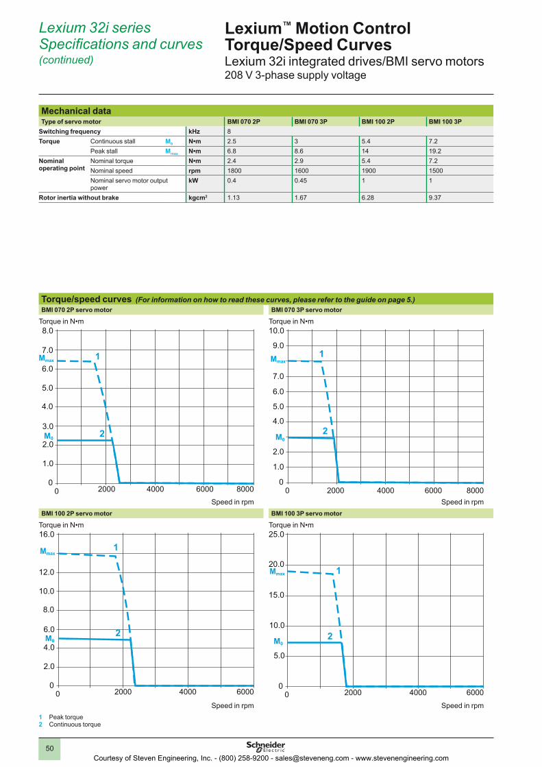
50
Lexium 32i seriesSpecifications and curves(continued)
Lexium™ Motion Control Torque/Speed CurvesLexium 32i integrated drives/BMI servo motors208 V 3-phase supply voltage
Mechanical dataType of servo motor BMI 070 2P BMI 070 3P BMI 100 2P BMI 100 3P
Switching frequency kHz 8Torque Continuous stall M0 N•m 2.5 3 5.4 7.2
Peak stall Mmax N•m 6.8 8.6 14 19.2Nominal operating point
Nominal torque N•m 2.4 2.9 5.4 7.2Nominal speed rpm 1800 1600 1900 1500Nominal servo motor output power
kW 0.4 0.45 1 1
Rotor inertia without brake kgcm2 1.13 1.67 6.28 9.37
Torque/speed curves (For information on how to read these curves, please refer to the guide on page 5.)BMI 070 2P servo motor BMI 070 3P servo motor
BMI 100 2P servo motor BMI 100 3P servo motor
1 Peak torque2 Continuous torque
0 2000 4000 800060000
1.0
2.0
3.0
4.0
6.0
5.0
7.0
8.0
2
Mmax
M0
1
Torque in N•m
Speed in rpm0 2000 4000 6000 8000
0
1.0
2.0
4.0
5.0
7.0
9.0
10.0
6.0
2
Mmax
M0
1
Torque in N•m
Speed in rpm
0 2000 4000 60000
2.0
4.0
6.0
8.0
12.0
10.0
16.0
2
Mmax
M0
1
Torque in N•m
Speed in rpm0 2000 4000 6000
0
5.0
10.0
20.0
15.0
25.0
2
Mmax
M0
1
Torque in N•m
Speed in rpm
Courtesy of Steven Engineering, Inc. - (800) 258-9200 - [email protected] - www.stevenengineering.com

51
Lexium 32i seriesSpecifications and curves(continued)
Lexium™ Motion Control Torque/Speed CurvesLexium 32i integrated drives/BMI servo motors400 V 3-phase supply voltage
Mechanical dataType of servo motor BMI 070 2P BMI 070 3P BMI 100 2P BMI 100 3P
Switching frequency kHz 8Torque Continuous stall M0 N•m 2.5 3 5.4 7.2
Peak stall Mmax N•m 6.8 8.6 14 19.2Nominal operating point
Nominal torque N•m 2.2 2.7 5.1 6.8Nominal speed rpm 3600 3300 3800 3000Nominal servo motor output power
kW 0.8 0.9 1.9 2
Rotor inertia without brake kgcm2 1.13 1.67 6.28 9.37
Torque/speed curves (For information on how to read these curves, please refer to the guide on page 5.)BMI 070 2P servo motor BMI 070 3P servo motor
BMI 100 2P servo motor BMI 100 3P servo motor
1 Peak torque2 Continuous torque
0 2000 4000 800060000
1.0
3.0
4.0
6.0
5.0
7.0
8.0
2
Mmax
M0
1
Torque in N•m
Speed in rpm0 2000 4000 6000 8000
0
1.0
2.0
4.0
5.0
7.0
9.0
10.0
6.0
2
Mmax
M0
1
Torque in N•m
Speed in rpm
0 2000 4000 60000
2.0
4.0
6.0
8.0
12.0
10.0
16.0
2
Mmax
M0
1
Torque in N•m
Speed in rpm0 2000 4000 6000
0
5.0
10.0
20.0
15.0
25.0
2
Mmax
M0
1
Torque in N•m
Speed in rpm
Courtesy of Steven Engineering, Inc. - (800) 258-9200 - [email protected] - www.stevenengineering.com

52
Lexium 32i seriesSpecifications and curves(continued)
Lexium™ Motion Control Torque/Speed CurvesLexium 32i integrated drives/BMI servo motors480 V 3-phase supply voltage
Mechanical dataType of servo motor BMI 070 2P BMI 070 3P BMI 100 2P BMI 100 3P
Switching frequency kHz 8Torque Continuous stall M0 N•m 2.5 3 5.4 7.2
Peak stall Mmax N•m 6.8 8.6 14 19.2Nominal operating point
Nominal torque N•m 2 2.3 4.1 5.6Nominal speed rpm 4400 3900 4700 3700Nominal servo motor output power
kW 0.9 0.9 1 2.1
Rotor inertia without brake kgcm2 1.13 1.67 6.28 9.37
Torque/speed curves (For information on how to read these curves, please refer to the guide on page 5.)BMI 070 2P servo motor BMI 070 3P servo motor
BMI 100 2P servo motor BMI 100 3P servo motor
1 Peak torque2 Continuous torque
0 2000 4000 800060000
1.0
3.0
4.0
6.0
5.0
7.0
8.0
2
Mmax
M0
1
Torque in N•m
Speed in rpm0 2000 4000 6000 8000
0
1.0
2.0
3.0
4.0
5.0
7.0
9.0
10.0
6.0
2
Mmax
M0
1
Torque in N•m
Speed in rpm
0 2000 4000 60000
2.0
6.0
8.0
12.0
10.0
16.0
2
Mmax
M0
1
Torque in N•m
Speed in rpm0 2000 4000 6000
0
5.0
10.0
20.0
15.0
25.0
2
Mmax
M0
1
Torque in N•m
Speed in rpm
Courtesy of Steven Engineering, Inc. - (800) 258-9200 - [email protected] - www.stevenengineering.com

53
Lexium™ ILp series
OverviewLexium™ Integrated Drives are used to create decentralized motion control solutions in very compact units.
These drives consist of a motor and control electronics. They are controlled via a communication bus, a pulse/direction (P/D) interface or an I/O interface (for the “Motion sequence” operating mode).
Lexium Integrated Drives are used as decentralized drives in machine building. When combined with a Schneider Electric Lexium Controller or a PLC, they can be used to create complex control system architectures simply and at minimum cost. Ready-to-use function blocks are available for programming movements with Schneider Electric or third-party motion controllers.
Compact designLexium motor and control electronics form a compact unit. This decentralized unit does not require any space in the enclosure for the control electronics, thus reducing the size of the machine.
Simple to install and commissionIntegration of the motor and the control electronics reduces installation costs and simplifies incorporation of electromagnetic compatibility. In addition, Lexium CT PC software enables rapid commissioning.
Optimum flexibility to adapt to your applicationLexium Integrated Drives can be equipped with an AC synchronous servo motor, a DC brushless motor or a stepper motor, providing multiple options for use in a wide variety of applications.Depending on the technology used, these drives can meet requirements for dynamic performance, flexibility or precision in motion control applications.
Open communication with control system architecturesDepending on the model, Lexium Integrated Drives incorporate as standard the main communication protocols used in industry for increased performance of your applications:
b CANopen, PROFIBUS DP, DeviceNet, EtherCAT, EtherNet/IP, Ethernet POWERLINK™ and Modbus TCP communication buses and networks
b RS 485 serial link
Lexium Integrated Drives with stepper motor are also available with a pulse/direction (P/D) interface or an I/O interface for the motion sequence.
This open communication concept enables integration in numerous control system architectures.
Courtesy of Steven Engineering, Inc. - (800) 258-9200 - [email protected] - www.stevenengineering.com

54
Lexium ILp seriesSpecifications and curves
Lexium™ Motion Control Torque/Speed CurvesILp1 for CANopen, PROFIBUS DP, RS 485ILA1 with AC synchronous servo motor
Mechanical dataType of integrated drive ILA1p571 ILA1p572
Winding type T P T PNominal supply voltage c V 24 36 24 36 24 36 24 36Nominal speed of rotation rpm 5100 7500 3200 5500 3100 5000 2600 4300Max. torque (1) Mmax N•m 0.43 0.6 0.61 0.72Continuous torque (2) M0 N•m 0.26 0.26 0.41 0.45Positioning resolution per revolution Inc. 16384 16384Accuracy of positioning sensor ° ±0.05 ±0.05Rotor inertia kgcm2 0.1 0.18Mass kg 1.4 1.7Shaft load Max. radial force (3) N 89 107
Max. axial tensile force N 104 104Max. axial force pressure N 104 104Nominal bearing service life (4) h 20000 20000
Holding brake (optional) (5)Holding torque N•m 1.2Electrical pull-in power W 10Brake release time ms 14Brake application time ms 13Moment of inertia kgcm2 0.07Multiturn encoder (optional) (5)
Measuring range absolute rpm 4096Positioning resolution per revolution Inc. 16384Accuracy of positioning sensor ° ±0.05(1) Max. 2.5 s(2) At 20 rpm; at 0 rpm the continuous torque is reduced to 89% of the specified value(3) Point of application of radial force: 10 mm distance to flange(4) Operating hours at a probability of failure of 10%; conditions for shaft load: speed 4000 rpm, 100% duty cycle at continuous torque, ambient temperature 40 °C(5) Holding brake and multiturn encoder cannot be used in combination.
Torque/speed curves (For information on how to read these curves, please refer to the guide on page 5.)ILA1p571T (winding type T) ILA1p571P (winding type P)
ILA1p572T (winding type T) ILA1p572P (winding type P)
1.1 Max. torque at 24 V 1.2 Max. torque at 36 V 2 Continuous torque
Torque in N•m
Speed in rpm
Torque in N•m
Speed in rpm
Torque in N•m
Speed in rpm
Torque in N•m
Speed in rpm
0 2000 4000 6000 80000
0.1
0.2
0.4
0.5
0.7
2
Mmax
M0
1.1 1.2
0 2000 4000 6000 8000 10000 120000
0.1
0.2
0.3
0.4
0.5
2
Mmax
M0
1.1 1.2
0 2000 4000 6000 800000.10.20.3
0.60.5
0.8
2
Mmax
M0
1.1 1.2
0 2000 4000 6000 80000
0.1
0.2
0.3
0.5
0.7
2
Mmax
M0
1.1 1.2
Courtesy of Steven Engineering, Inc. - (800) 258-9200 - [email protected] - www.stevenengineering.com

55
Lexium ILp seriesSpecifications and curves(continued)
Lexium™ Motion Control Torque/Speed CurvesILp1 for CANopen, PROFIBUS DP, RS 485ILE1 with brushless DC motor (without gear)
Mechanical dataNominal supply voltage c V 24 36Nominal current A 4.7 5.1Nominal speed of rotation rpm 4000 4800Nominal output power W 74 117Nominal torque N•m 0.175 0.24Max. torque Mmax N•m 0.26 0.36Max. current with power stage disabled A 0.1 0.06Detent torque (at zero current) N•m 0.08Moment of inertia kgcm2 0.149Max. speed of rotation rpm 5000Positioning resolution per revolution Inc. 12Accuracy of positioning sensor ° ±1Mass kg 1.4Shaft load Max. radial force (1) N 80
Max. axial tensile force N 30Max. axial force pressure N 30Nominal bearing service life (2) h 20000
(1) Point of application of radial force: 12.5 mm distance to flange(2) Operating hours at a probability of failure of 10%
Torque/speed curves (For information on how to read these curves, please refer to the guide on page 5.)ILE1 without gear
1.1 Max. torque at 24 V 1.2 Max. torque at 36 V
Torque in N•m
Speed in rpm
Torque characteristicsILE1 without gearing ILE1p661 with straight teeth gear G1 ILE1p661 with worm gear G5
0 1000 2000 3000 500040000
0.05
0.1
0.2
0.15
0.25
0.3
1.1
1.2
0/ 1000/ 2000/ 3000/ 5000/4000/0 55 110 166 270222
00.51
21.5
32.5
4.5
3.54
1.1
1.2
0/ 1000/ 2000/ 3000/ 5000/4000/0 41.6 83.8 125.7 209.5167.6
00.51
21.5
32.5
4.5
3.54
1.1
1.2
ILE1p661 with straight teeth gear G2 ILE1p661 with worm gear G6
0/ 1000/ 2000/ 3000/ 5000/4000/0 26 52 78 130105
012
43
65
9
78
1.1
1.2
0/ 1000/ 2000/ 3000/ 5000/4000/0 18.6 37.3 56 93.274.6
012
43
65
9
78
1.1
1.2
ILE1p661 with straight teeth gear G3 ILE1p661 with worm gear G7
0/ 1000/ 2000/ 3000/ 5000/4000/0 18 37 55 9274
0
2
4
8
6
12
10
14
1.1
1.2
0/ 1000/ 2000/ 3000/ 5000/4000/0 10.9 21.8 32.6 54.443.5
0
2
4
8
6
12
10
14
1.1
1.2
ILE1p661 with straight teeth gear G4 ILE1p661 with worm gear G8
0/ 1000/ 2000/ 3000/ 5000/4000/0 8 .7 17.4 26 4335
024
86
1210
1614
1.1
1.2
0/ 1000/ 2000/ 3000/ 5000/4000/0 8.7 17.4 26.1 43.534.8
024
86
1210
1614
1.1
1.2
Courtesy of Steven Engineering, Inc. - (800) 258-9200 - [email protected] - www.stevenengineering.com

56
Mechanical data for ILE1p661 with straight teeth gearG1 G2 G3 G4
Ratio 18:1 (160:9) 38:1 (75:2) 54:1 (490:9) 115:1 (3675:32)Number of gear stages 3 3 4 4Nominal supply voltage c V 24 36 24 36 24 36 24 36Nominal current A 4.5 4 4 3.4 4.3 3.5 2.6 2.1Nominal speed of rotation of motor rpm 4000 4800 4000 4800 4000 4800 4000 4800Nominal output speed of rotation rpm 225 270 107 128 73 88 35 42Nominal output torque N•m 3.1 3.5 5.8 6.0 9.5 10.0 10.0 11.0Nominal output power W 74 98 65 81 73 88 38 48Max. current with power stage disabled A 0.1 0.06 0.1 0.06 0.1 0.06 0.1 0.06Detent torque (at zero current) N•m 1.1 3.0 3.3 8.0Moment of inertia output kgcm2 48 211 441 1962Max. speed of rotation rpm 281 133 92 44Positioning resolution of motor per revolution Inc. 12Positioning accuracy motor Inc. ±1Positioning resolution of output ° 1.667 0.8 0.55 0.26Torsional backlash ° ≤1Mass kg 1.85Shaft load (short-term operation)
Max. radial force (1) N 200Max. axial force N 80Nominal bearing service life (2) h 2500
Shaft load (long-term operation)
Max. radial force (1) N 200Max. axial force N 10Nominal bearing service life (2) h 15000 15000 15000 (3) 15000 (4)
(1) Point of application of radial force: 12.5 mm distance to flange(2) Operating hours at a probability of failure of 10%(3) With reduced nominal output torque = 6 N•m; 2500 h at maximum torque(4) With reduced nominal output torque = 8 N•m; 2500 h at maximum torque
Torque/speed curves (For information on how to read these curves, please refer to the guide on page 5.)ILE1p661 with straight teeth gear G1 ILE1p661 with straight teeth gear G2
ILE1p661 with straight teeth gear G3 ILE1p661 with straight teeth gear G4
1.1 Max. torque at 24 V 1.2 Max. torque at 36 V
Torque characteristicsILE1 without gearing ILE1p661 with straight teeth gear G1 ILE1p661 with worm gear G5
0 1000 2000 3000 500040000
0.05
0.1
0.2
0.15
0.25
0.3
1.1
1.2
0/ 1000/ 2000/ 3000/ 5000/4000/0 55 110 166 270222
00.51
21.5
32.5
4.5
3.54
1.1
1.2
0/ 1000/ 2000/ 3000/ 5000/4000/0 41.6 83.8 125.7 209.5167.6
00.51
21.5
32.5
4.5
3.54
1.1
1.2
ILE1p661 with straight teeth gear G2 ILE1p661 with worm gear G6
0/ 1000/ 2000/ 3000/ 5000/4000/0 26 52 78 130105
012
43
65
9
78
1.1
1.2
0/ 1000/ 2000/ 3000/ 5000/4000/0 18.6 37.3 56 93.274.6
012
43
65
9
78
1.1
1.2
ILE1p661 with straight teeth gear G3 ILE1p661 with worm gear G7
0/ 1000/ 2000/ 3000/ 5000/4000/0 18 37 55 9274
0
2
4
8
6
12
10
14
1.1
1.2
0/ 1000/ 2000/ 3000/ 5000/4000/0 10.9 21.8 32.6 54.443.5
0
2
4
8
6
12
10
14
1.1
1.2
ILE1p661 with straight teeth gear G4 ILE1p661 with worm gear G8
0/ 1000/ 2000/ 3000/ 5000/4000/0 8 .7 17.4 26 4335
024
86
1210
1614
1.1
1.2
0/ 1000/ 2000/ 3000/ 5000/4000/0 8.7 17.4 26.1 43.534.8
024
86
1210
1614
1.1
1.2
Lexium ILp seriesSpecifications and curves(continued)
Lexium™ Motion Control Torque/Speed CurvesILp1 for CANopen, PROFIBUS DP, RS 485ILE1 with brushless DC motor (with straight teeth gear)
Torq
ue in
N•m
Speed of motor in rpm/Speed of gearing in rpm
Torque characteristicsILE1 without gearing ILE1p661 with straight teeth gear G1 ILE1p661 with worm gear G5
0 1000 2000 3000 500040000
0.05
0.1
0.2
0.15
0.25
0.3
1.1
1.2
0/ 1000/ 2000/ 3000/ 5000/4000/0 55 110 166 270222
00.51
21.5
32.5
4.5
3.54
1.1
1.2
0/ 1000/ 2000/ 3000/ 5000/4000/0 41.6 83.8 125.7 209.5167.6
00.51
21.5
32.5
4.5
3.54
1.1
1.2
ILE1p661 with straight teeth gear G2 ILE1p661 with worm gear G6
0/ 1000/ 2000/ 3000/ 5000/4000/0 26 52 78 130105
012
43
65
9
78
1.1
1.2
0/ 1000/ 2000/ 3000/ 5000/4000/0 18.6 37.3 56 93.274.6
012
43
65
9
78
1.1
1.2
ILE1p661 with straight teeth gear G3 ILE1p661 with worm gear G7
0/ 1000/ 2000/ 3000/ 5000/4000/0 18 37 55 9274
0
2
4
8
6
12
10
14
1.1
1.2
0/ 1000/ 2000/ 3000/ 5000/4000/0 10.9 21.8 32.6 54.443.5
0
2
4
8
6
12
10
14
1.1
1.2
ILE1p661 with straight teeth gear G4 ILE1p661 with worm gear G8
0/ 1000/ 2000/ 3000/ 5000/4000/0 8 .7 17.4 26 4335
024
86
1210
1614
1.1
1.2
0/ 1000/ 2000/ 3000/ 5000/4000/0 8.7 17.4 26.1 43.534.8
024
86
1210
1614
1.1
1.2
Torq
ue in
N•m
Speed of motor in rpm/Speed of gearing in rpm
Courtesy of Steven Engineering, Inc. - (800) 258-9200 - [email protected] - www.stevenengineering.com

57
Lexium ILp seriesSpecifications and curves(continued)
Lexium™ Motion Control Torque/Speed CurvesILp1 for CANopen, PROFIBUS DP, RS 485ILE1 with brushless DC motor (with worm gear)
Mechanical data for ILE1p661 with worm gearG5 G6 G7 G8
Ratio 24:1 (525:22) 54:1 (1715:32) 92:1 (735:5) 115:1 (3675:32)Number of gear stages 2 3 3 3Nominal supply voltage c V 24 36 24 36 24 36 24 36Nominal current A 6.8 5.1 6.8 3.8 6.8 3.8 6.8 3.8Nominal speed of rotation of motor rpm 4000 4000 4000 4000 4000 4000 4000 4000Nominal output speed of rotation rpm 168 75 44 35Nominal output torque N•m 2.5 3.5 5.8 6.0 9.0 9.2 10.2 10.6Nominal output power W 45 61 45 47 41 42 37 39Max. current with power stage disabled A 0.1Detent torque (at zero current) N•m 2.9 6.5 12.3 16.7Moment of inertia output kgcm2 90 430 1270 1980Max. speed of rotation rpm 186 93 54 44Positioning resolution of motor per revolution Inc. 12Positioning accuracy motor Inc. ±1Positioning resolution of output ° 1.26 0.56 0.33 0.26Torsional backlash ° ≤1.5 ≤1.0 ≤1.0 ≤1.0Mass kg 2.3Shaft load Max. radial force (1) N 200
Max. axial force N 80Nominal bearing service life (2) h 3000 6000 9000 9000
(1) Point of application of radial force: 12.5 mm distance to flange(2) Operating hours at a probability of failure of 10%
Torque/speed curves (For information on how to read these curves, please refer to the guide on page 5.)ILE1p661 with worm gear G5 ILE1p661 with worm gear G6
ILE1p661 with worm gear G7 ILE1p661 with worm gear G8
1.1 Max. torque at 24 V 1.2 Max. torque at 36 V
Torque characteristicsILE1 without gearing ILE1p661 with straight teeth gear G1 ILE1p661 with worm gear G5
0 1000 2000 3000 500040000
0.05
0.1
0.2
0.15
0.25
0.3
1.1
1.2
0/ 1000/ 2000/ 3000/ 5000/4000/0 55 110 166 270222
00.51
21.5
32.5
4.5
3.54
1.1
1.2
0/ 1000/ 2000/ 3000/ 5000/4000/0 41.6 83.8 125.7 209.5167.6
00.51
21.5
32.5
4.5
3.54
1.1
1.2
ILE1p661 with straight teeth gear G2 ILE1p661 with worm gear G6
0/ 1000/ 2000/ 3000/ 5000/4000/0 26 52 78 130105
012
43
65
9
78
1.1
1.2
0/ 1000/ 2000/ 3000/ 5000/4000/0 18.6 37.3 56 93.274.6
012
43
65
9
78
1.1
1.2
ILE1p661 with straight teeth gear G3 ILE1p661 with worm gear G7
0/ 1000/ 2000/ 3000/ 5000/4000/0 18 37 55 9274
0
2
4
8
6
12
10
14
1.1
1.2
0/ 1000/ 2000/ 3000/ 5000/4000/0 10.9 21.8 32.6 54.443.5
0
2
4
8
6
12
10
14
1.1
1.2
ILE1p661 with straight teeth gear G4 ILE1p661 with worm gear G8
0/ 1000/ 2000/ 3000/ 5000/4000/0 8 .7 17.4 26 4335
024
86
1210
1614
1.1
1.2
0/ 1000/ 2000/ 3000/ 5000/4000/0 8.7 17.4 26.1 43.534.8
024
86
1210
1614
1.1
1.2
Torq
ue in
N•m
Speed of motor in rpm/Speed of gearing in rpm
Courtesy of Steven Engineering, Inc. - (800) 258-9200 - [email protected] - www.stevenengineering.com

58
Mechanical dataType of integrated drive ILS1p571 ILS1p572 ILS1p573
Winding type P P PMax. torque N•m 0.45 0.9 1.5Holding torque N•m 0.51 1.02 1.70Moment of inertia kgcm2 0.1 0.22 0.38Positioning resolution per revolution Inc. 20000Systematic angle tolerance per step (1) arcmin ±6Mass kg 1.3 1.6 2.0Shaft load (2) Max. radial force (3) N 24 24 50
Max. axial tensile force N 100Max. axial force pressure N 8.4Nominal bearing service life (4) h 20000
(1) Measured at 1000 steps/revolution(2) Conditions for shaft load: speed of rotation 60 rpm, 100% duty cycle at continuous torque, ambient temperature 40 °C(3) Point of application of radial force: 10.5 mm distance to flange(4) Operating hours at a probability of failure of 10%
Torque/speed curves (For information on how to read these curves, please refer to the guide on page 5.)ILS1p571P (winding type P) ILS1p572P (winding type P)
ILS1p573P (winding type P)
1.1 Max. torque at 24 V 1.2 Max. torque at 36 V
Torque characteristics ILS1p57ILS1p571P (winding type P) ILS1p572P (winding type P) ILS1p573P (winding type P)
10 100 1000010000
0.1
0.2
0.3
0.4
0.5
1.1
1.2
10 100 1000010000
0.2
0.4
0.6
0.8
1
1.1
1.2
10 100 1000010000
0.4
0.8
1.2
1.6
2
1.11.2
Torque characteristics ILS1p85ILS1p851P (winding type P) ILS1p852P (winding type P)
10 100 1000010000
0.5
1
2
1.5
2.5
3
1.11.2
10 100 1000010000
1
2
3
4
5
1.1
1.2
ILS1p853P (winding type P) ILS1p853T (winding type T)
10 100 1000010000
1
2
4
3
6
5
7
1.1
1.2
10 100 1000010000
1
2
4
3
6
5
7
1.11.2
Lexium ILp seriesSpecifications and curves(continued)
Lexium™ Motion Control Torque/Speed CurvesILp1 for CANopen, PROFIBUS DP, RS 485ILS1 with 3-phase stepper motor
Torq
ue in
N•m
Speed in rpm
Torq
ue in
N•m
Speed in rpm
Torq
ue in
N•m
Torque characteristics ILS1p57ILS1p571P (winding type P) ILS1p572P (winding type P) ILS1p573P (winding type P)
10 100 1000010000
0.1
0.2
0.3
0.4
0.5
1.1
1.2
10 100 1000010000
0.2
0.4
0.6
0.8
1
1.1
1.2
10 100 1000010000
0.4
0.8
1.2
1.6
2
1.11.2
Torque characteristics ILS1p85ILS1p851P (winding type P) ILS1p852P (winding type P)
10 100 1000010000
0.5
1
2
1.5
2.5
3
1.11.2
10 100 1000010000
1
2
3
4
5
1.1
1.2
ILS1p853P (winding type P) ILS1p853T (winding type T)
10 100 1000010000
1
2
4
3
6
5
7
1.1
1.2
10 100 1000010000
1
2
4
3
6
5
7
1.11.2
Speed in rpm
Courtesy of Steven Engineering, Inc. - (800) 258-9200 - [email protected] - www.stevenengineering.com

59
Lexium ILp seriesSpecifications and curves(continued)
Lexium™ Motion Control Torque/Speed CurvesILp1 for CANopen, PROFIBUS DP, RS 485ILS1 with 3-phase stepper motor
Mechanical dataType of integrated drive ILS1p851 ILS1p852 ILS1p853
Winding type P P P TMax. torque N•m 2.0 4.0 6.0 4.5Holding torque N•m 2.0 4.0 6.0 4.5Moment of inertia kgcm2 1.1 2.2 3.3Positioning resolution Inc. 20000Systematic angle tolerance per step (1) arcmin ±6Mass kg 2.6 3.6 4.7Shaft load (2) Max. radial force (3) N 100 100 110
Max. axial tensile force N 170Max. axial force pressure N 30Nominal bearing service life (4) h 20000
Holding BrakeHolding torque N•m 6Electrical pull-in power W 22Brake release time ms 40Brake application time ms 20Moment of inertia kgcm2 0.2Mass kg 1.8(1) Measured at 1000 steps/revolution(2) Conditions for shaft load: speed of rotation 60 rpm, 100% duty cycle at continuous torque, ambient temperature 40 °C(3) Point of application of radial force: 10.5 mm distance to flange(4) Operating hours at a probability of failure of 10%
Torque/speed curves (For information on how to read these curves, please refer to the guide on page 5.)ILS1p851P (winding type P) ILS1p852P (winding type P)
ILS1p853P (winding type P) ILS1p853T (winding type T)
1.1 Max. torque at 24 V 1.2 Max. torque at 36 V
Torq
ue in
N•m
Speed in rpm
Torq
ue in
N•m
Speed in rpm
Torq
ue in
N•m
Speed in rpm
Torq
ue in
N•m
Speed in rpm
Torque characteristics ILS1p57ILS1p571P (winding type P) ILS1p572P (winding type P) ILS1p573P (winding type P)
10 100 1000010000
0.1
0.2
0.3
0.4
0.5
1.1
1.2
10 100 1000010000
0.2
0.4
0.6
0.8
1
1.1
1.2
10 100 1000010000
0.4
0.8
1.2
1.6
2
1.11.2
Torque characteristics ILS1p85ILS1p851P (winding type P) ILS1p852P (winding type P)
10 100 1000010000
0.5
1
2
1.5
2.5
3
1.11.2
10 100 1000010000
1
2
3
4
5
1.1
1.2
ILS1p853P (winding type P) ILS1p853T (winding type T)
10 100 1000010000
1
2
4
3
6
5
7
1.1
1.2
10 100 1000010000
1
2
4
3
6
5
7
1.11.2
Courtesy of Steven Engineering, Inc. - (800) 258-9200 - [email protected] - www.stevenengineering.com

60
Lexium ILp seriesSpecifications and curves(continued)
Lexium™ Motion Control Torque/Speed CurvesILp2 for DeviceNet, EtherCAT, Modbus TCP, Ethernet PowerlinkILA2 with AC synchronous servo motor
Mechanical dataType of integrated drive ILA2p571 ILA2p572
Winding type T P T PNominal supply voltage c V 24 48 24 48 24 48 24 48Nominal speed of rotation rpm 5000 7000 3200 5100 3000 5100 1600 3400Max. torque (1) Mmax N•m 0.45 0.62 0.85 1.62Continuous torque (2) M0 N•m 0.31 0.44 0.57 0.78Positioning resolution per revolution Inc. 16384 16384Accuracy of positioning sensor ° ±0.05 ±0.05Rotor inertia kgcm2 0.095 0.173Mass kg 1.4 1.7Shaft load Max. radial force (3) N 89 107
Max. axial tensile force N 104 104Max. axial force pressure N 104 104Nominal bearing service life (4) h 20000 20000
Holding brake (optional) (5)Holding torque N•m 1.2Electrical pull-in power W 10Brake release time ms 14Brake application time ms 13Moment of inertia kgcm2 0.07Multiturn encoder (optional) (5)
Measuring range absolute rpm 4096Positioning resolution per revolution Inc. 16384Accuracy of positioning sensor ° ±0.05(1) Max. 2.5 s(2) At 20 rpm; at 0 rpm the continuous torque is reduced to 89% of the specified value(3) Point of application of radial force: 10 mm distance to flange(4) Operating hours at a probability of failure of 10%; conditions for shaft load: speed 4000 rpm, 100% duty cycle at continuous torque, ambient temperature 40 °C(5) Holding brake and multiturn encoder cannot be used in combination.
Torque/speed curves (For information on how to read these curves, please refer to the guide on page 5.)ILA2p571T (winding type T) ILA2p571P (winding type P)
ILA2p572T (winding type T) ILA2p572P (winding type P)
1.1 Max. torque at 24 V 1.2 Max. torque at 48 V 2 Continuous torque
Torque in N•m
Speed in rpm
Torque in N•m
Speed in rpm
Torque in N•m
Speed in rpm
Torque in N•m
Speed in rpm
Torque characteristicsILA2p571T (winding type T) ILA2p571P (winding type P)
0 30001000 5000 7000 90000
0.1
0.2
0.3
0.4
0.5
2
Mmax
M0 1.11.2
2
Mmax
M01.1
1.2
1000 3000 5000 70000
0.7
0.5
0.3
0.2
0.1
0
ILA2p572T (winding type T) ILA2p572P (winding type P)
0 1000 3000 5000 700000.10.20.30.40.5 2
1.1 1.20.70.6
Mmax
M0
0.80.9
0 20001000 50003000 40000
0.3
0.6
0.9
1.2
1.5
1.8
2
Mmax
M0
1.1
1.2
Courtesy of Steven Engineering, Inc. - (800) 258-9200 - [email protected] - www.stevenengineering.com

61
Lexium ILp seriesSpecifications and curves(continued)
Lexium™ Motion Control Torque/Speed CurvesILp2 for DeviceNet, EtherCAT, Modbus TCP, Ethernet PowerlinkILE2 with brushless DC motor (without gear)
Mechanical dataType of integrated drive ILE2p661 ILE2p662
Nominal supply voltage c V 24 48 24 48Nominal current A 6.8 3.8 9.5 7Nominal speed of rotation rpm 4800 6000 3100 5000Nominal output power W 131 163 162 262Nominal torque N•m 0.26 0.5Max. torque Mmax N•m 0.43 0.8Max. current with power stage disabled A 0.1Detent torque (at zero current) N•m 0.08 0.106Moment of inertia kgcm2 0.17 0.34Max. speed of rotation rpm 6500 7000 5000 7000Positioning resolution per revolution Inc. 12Accuracy of positioning sensor ° ±0.5Mass kg 1.4 1.75Shaft load Max. radial force (1) N 80
Max. axial tensile force N 30Max. axial force pressure N 30Nominal bearing service life (2) h 20000
(1) Point of application of radial force: 12.5 mm distance to flange(2) Operating hours at a probability of failure of 10%
Torque/speed curves (For information on how to read these curves, please refer to the guide on page 5.)ILE2p661 without gear ILE2p662 without gear
1.1 Max. torque at 24 V 1.2 Max. torque at 48 V
Torque in N•m
Speed in rpm
Torque characteristics ILE2p66ILE2p661 without gearing ILE2p661 with straight teeth gear G1 ILE2p661 with worm gear G5
0 1000 3000 5000 70000
0.05
0.1
0.2
0.15
0.25
0.3
1.1
1.2
0/ 1000/ 2000/ 3000/ 5000/4000/0 55 110 166 270222
00.51
21.5
32.5
4.5
3.54
1.1
1.2
0/ 1000/ 2000/ 3000/ 5000/4000/0 41.6 83.8 125.7 209.5167.6
00.51
21.5
32.5
4.5
3.54
1.1
1.2
ILE2p662 without gearing ILE2p661 with straight teeth gear G2 ILE2p661 with worm gear G6
0 1000 3000 5000 70000
0.1
0.2
0.4
0.3
0.6
0.5
0.7
1.1
1.2
0/ 1000/ 2000/ 3000/ 5000/4000/0 26 52 78 130105
012
43
65
9
78
1.1
1.2
0/ 1000/ 2000/ 3000/ 5000/4000/0 18.6 37.3 56 93.274.6
012
43
65
9
78
1.1
1.2
ILE2p661 with straight teeth gear G3 ILE2p661 with worm gear G7
0/ 1000/ 2000/ 3000/ 5000/4000/0 18 37 55 9274
0
2
4
8
6
12
10
14
1.1
1.2
0/ 1000/ 2000/ 3000/ 5000/4000/0 10.9 21.8 32.6 54.443.5
0
2
4
8
6
12
10
14
1.1
1.2
ILE2p661 with straight teeth gear G4 ILE2p661 with worm gear G8
0/ 1000/ 2000/ 3000/ 5000/4000/0 8.7 17.4 26 4335
024
86
1210
1614
1.1
1.2
0/ 1000/ 2000/ 3000/ 5000/4000/0 8.7 17.4 26.1 43.534.8
024
86
1210
1614
1.1
1.2
Courtesy of Steven Engineering, Inc. - (800) 258-9200 - [email protected] - www.stevenengineering.com

62
Mechanical data for ILE2p661 with straight teeth gearG1 G2 G3 G4
Ratio 18:1 (160:9) 38:1 (75:2) 54:1 (490:9) 115:1 (3675:32)Number of gear stages 3 3 4 4Nominal supply voltage c V 24 48 24 48 24 48 24 48Nominal current A 6.8 3.8 6.8 3.8 6.8 3.8 6.8 3.8Nominal speed of rotation of motor rpm 4000 5000 4000 5000 4000 5000 4000 5000Nominal output speed of rotation rpm 225 281 107 133 73 92 35 44Nominal output torque N•m 3.5 7.3 10 12Nominal output power W 95 119 95 119 90 112 54 68Max. current with power stage disabled A 0.1Detent torque (at zero current) N•m 1.42 3.00 4.36 9.19Moment of inertia output kgcm2 48 211 441 1962Max. speed of rotation rpm 281 133 92 44Positioning resolution of motor per revolution Inc. 12Positioning accuracy motor Inc. ±0.5Positioning resolution of output ° 1.667 0.8 0.55 0.26Torsional backlash ° ≤1Mass kg 1.85Shaft load (short-term operation)
Max. radial force (1) N 200Max. axial force N 80Nominal bearing service life (2) h 2500
Shaft load (long-term operation)
Max. radial force (1) N 200Max. axial force N 10Nominal bearing service life (2) h 15000 15000 15000 (3) 15000 (4)
(1) Point of application of radial force: 12.5 mm distance to flange(2) Operating hours at a probability of failure of 10%(3) With reduced nominal output torque = 6 N•m; 2500 h at maximum torque(4) With reduced nominal output torque = 8 N•m; 2500 h at maximum torque
Torque/speed curves (For information on how to read these curves, please refer to the guide on page 5.)ILE2p661 with straight teeth gear G1 ILE2p661 with straight teeth gear G2
ILE2p661 with straight teeth gear G3 ILE2p661 with straight teeth gear G4
1.1 Max. torque at 24 V 1.2 Max. torque at 48 V
Torque characteristics ILE2p66ILE2p661 without gearing ILE2p661 with straight teeth gear G1 ILE2p661 with worm gear G5
0 1000 3000 5000 70000
0.05
0.1
0.2
0.15
0.25
0.3
1.1
1.2
0/ 1000/ 2000/ 3000/ 5000/4000/0 55 110 166 270222
00.51
21.5
32.5
4.5
3.54
1.1
1.2
0/ 1000/ 2000/ 3000/ 5000/4000/0 41.6 83.8 125.7 209.5167.6
00.51
21.5
32.5
4.5
3.54
1.1
1.2
ILE2p662 without gearing ILE2p661 with straight teeth gear G2 ILE2p661 with worm gear G6
0 1000 3000 5000 70000
0.1
0.2
0.4
0.3
0.6
0.5
0.7
1.1
1.2
0/ 1000/ 2000/ 3000/ 5000/4000/0 26 52 78 130105
012
43
65
9
78
1.1
1.2
0/ 1000/ 2000/ 3000/ 5000/4000/0 18.6 37.3 56 93.274.6
012
43
65
9
78
1.1
1.2
ILE2p661 with straight teeth gear G3 ILE2p661 with worm gear G7
0/ 1000/ 2000/ 3000/ 5000/4000/0 18 37 55 9274
0
2
4
8
6
12
10
14
1.1
1.2
0/ 1000/ 2000/ 3000/ 5000/4000/0 10.9 21.8 32.6 54.443.5
0
2
4
8
6
12
10
14
1.1
1.2
ILE2p661 with straight teeth gear G4 ILE2p661 with worm gear G8
0/ 1000/ 2000/ 3000/ 5000/4000/0 8.7 17.4 26 4335
024
86
1210
1614
1.1
1.2
0/ 1000/ 2000/ 3000/ 5000/4000/0 8.7 17.4 26.1 43.534.8
024
86
1210
1614
1.1
1.2
Lexium ILp seriesSpecifications and curves(continued)
Lexium™ Motion Control Torque/Speed CurvesILp2 for DeviceNet, EtherCAT, Modbus TCP, Ethernet PowerlinkILE2 with brushless DC motor (with straight teeth gear)
Torq
ue in
N•m
Speed of motor in rpm/Speed of gearing in rpm
Torq
ue in
N•m
Speed of motor in rpm/Speed of gearing in rpm
Torq
ue in
N•m
Speed of motor in rpm/Speed of gearing in rpm
Torq
ue in
N•m
Speed of motor in rpm/Speed of gearing in rpm
Torque characteristics ILE2p66ILE2p661 without gearing ILE2p661 with straight teeth gear G1 ILE2p661 with worm gear G5
0 1000 3000 5000 70000
0.05
0.1
0.2
0.15
0.25
0.3
1.1
1.2
0/ 1000/ 2000/ 3000/ 5000/4000/0 55 110 166 270222
00.51
21.5
32.5
4.5
3.54
1.1
1.2
0/ 1000/ 2000/ 3000/ 5000/4000/0 41.6 83.8 125.7 209.5167.6
00.51
21.5
32.5
4.5
3.54
1.1
1.2
ILE2p662 without gearing ILE2p661 with straight teeth gear G2 ILE2p661 with worm gear G6
0 1000 3000 5000 70000
0.1
0.2
0.4
0.3
0.6
0.5
0.7
1.1
1.2
0/ 1000/ 2000/ 3000/ 5000/4000/0 26 52 78 130105
012
43
65
9
78
1.1
1.2
0/ 1000/ 2000/ 3000/ 5000/4000/0 18.6 37.3 56 93.274.6
012
43
65
9
78
1.1
1.2
ILE2p661 with straight teeth gear G3 ILE2p661 with worm gear G7
0/ 1000/ 2000/ 3000/ 5000/4000/0 18 37 55 9274
0
2
4
8
6
12
10
14
1.1
1.2
0/ 1000/ 2000/ 3000/ 5000/4000/0 10.9 21.8 32.6 54.443.5
0
2
4
8
6
12
10
14
1.1
1.2
ILE2p661 with straight teeth gear G4 ILE2p661 with worm gear G8
0/ 1000/ 2000/ 3000/ 5000/4000/0 8.7 17.4 26 4335
024
86
1210
1614
1.1
1.2
0/ 1000/ 2000/ 3000/ 5000/4000/0 8.7 17.4 26.1 43.534.8
024
86
1210
1614
1.1
1.2
Courtesy of Steven Engineering, Inc. - (800) 258-9200 - [email protected] - www.stevenengineering.com

63
Lexium ILp seriesSpecifications and curves(continued)
Lexium™ Motion Control Torque/Speed CurvesILp2 for DeviceNet, EtherCAT, Modbus TCP, Ethernet PowerlinkILE2 with brushless DC motor (with worm gear)
Mechanical data for ILE2p661 with worm gearG5 G6 G7 G8
Ratio 24:1 (525:22) 54:1 (1715:32) 92:1 (735:5) 115:1 (3675:32)Number of gear stages 2 3 3 3Nominal supply voltage c V 24 48 24 48 24 48 24 48Nominal current A 6.8 3.8 6.8 2.7 6.8 2.6 6.8 2.9Nominal speed of rotation of motor rpm 4000 4000 4000 4000 4000 4000 4000 4000Nominal output speed of rotation rpm 168 75 44 35Nominal output torque N•m 3.8 6.0 9.2 10.6Nominal output power W 45 66 45 47 41 42 37 39Max. current with power stage disabled A 0.1Detent torque (at zero current) N•m 2.9 6.5 12.3 16.7Moment of inertia output kgcm2 90 430 1270 1980Max. speed of rotation rpm 186 93 54 44Positioning resolution of motor per revolution Inc. 12Positioning accuracy motor Inc. ±1Positioning resolution of output ° 1.26 0.56 0.33 0.26Torsional backlash ° ≤1.5 ≤1.0 ≤1.0 ≤1.0Mass kg 2.3Shaft load Max. radial force (1) N 200
Max. axial force N 80Nominal bearing service life (2) h 3000 6000 9000 9000
(1) Point of application of radial force: 12.5 mm distance to flange(2) Operating hours at a probability of failure of 10%
Torque/speed curves (For information on how to read these curves, please refer to the guide on page 5.)ILE1p661 with worm gear G5 ILE1p661 with worm gear G6
ILE1p661 with worm gear G7 ILE1p661 with worm gear G8
1.1 Max. torque at 24 V 1.2 Max. torque at 48 V
Torq
ue in
N•m
Speed of motor in rpm/Speed of gearing in rpm
Torq
ue in
N•m
Speed of motor in rpm/Speed of gearing in rpm
Torq
ue in
N•m
Speed of motor in rpm/Speed of gearing in rpm
Torq
ue in
N•m
Speed of motor in rpm/Speed of gearing in rpm
Torque characteristics ILE2p66ILE2p661 without gearing ILE2p661 with straight teeth gear G1 ILE2p661 with worm gear G5
0 1000 3000 5000 70000
0.05
0.1
0.2
0.15
0.25
0.3
1.1
1.2
0/ 1000/ 2000/ 3000/ 5000/4000/0 55 110 166 270222
00.51
21.5
32.5
4.5
3.54
1.1
1.2
0/ 1000/ 2000/ 3000/ 5000/4000/0 41.6 83.8 125.7 209.5167.6
00.51
21.5
32.5
4.5
3.54
1.1
1.2
ILE2p662 without gearing ILE2p661 with straight teeth gear G2 ILE2p661 with worm gear G6
0 1000 3000 5000 70000
0.1
0.2
0.4
0.3
0.6
0.5
0.7
1.1
1.2
0/ 1000/ 2000/ 3000/ 5000/4000/0 26 52 78 130105
012
43
65
9
78
1.1
1.2
0/ 1000/ 2000/ 3000/ 5000/4000/0 18.6 37.3 56 93.274.6
012
43
65
9
78
1.1
1.2
ILE2p661 with straight teeth gear G3 ILE2p661 with worm gear G7
0/ 1000/ 2000/ 3000/ 5000/4000/0 18 37 55 9274
0
2
4
8
6
12
10
14
1.1
1.2
0/ 1000/ 2000/ 3000/ 5000/4000/0 10.9 21.8 32.6 54.443.5
0
2
4
8
6
12
10
14
1.1
1.2
ILE2p661 with straight teeth gear G4 ILE2p661 with worm gear G8
0/ 1000/ 2000/ 3000/ 5000/4000/0 8.7 17.4 26 4335
024
86
1210
1614
1.1
1.2
0/ 1000/ 2000/ 3000/ 5000/4000/0 8.7 17.4 26.1 43.534.8
024
86
1210
1614
1.1
1.2
Courtesy of Steven Engineering, Inc. - (800) 258-9200 - [email protected] - www.stevenengineering.com

64
Mechanical dataType of integrated drive ILS2p571 ILS2p572 ILS2p573
Winding type P P PMax. torque N•m 0.45 0.9 1.5Holding torque N•m 0.45 0.9 1.5Moment of inertia kgcm2 0.1 0.22 0.38Positioning resolution per revolution Inc. 20000Systematic angle tolerance per step (1) arcmin ±6Mass kg 1.3 1.6 2.0Shaft load (2) Max. radial force (3) N 24 24 50
Max. axial tensile force N 100Max. axial force pressure N 8.4Nominal bearing service life (4) h 20000
(1) Measured at 1000 steps/revolution(2) Conditions for shaft load: speed of rotation 60 rpm, 100% duty cycle at continuous torque, ambient temperature 40 °C(3) Point of application of radial force: 10.5 mm distance to flange(4) Operating hours at a probability of failure of 10%
Torque/speed curves (For information on how to read these curves, please refer to the guide on page 5.)ILS2p571P (winding type P) ILS2p572P (winding type P)
ILS2p573P (winding type P)
1.1 Max. torque at 24 V 1.2 Max. torque at 48 V
Torque characteristics ILS2p57ILS2p571P (winding type P) ILS2p572P (winding type P) ILS2p573P (winding type P)
10 100 1000010000
0.1
0.2
0.3
0.4
0.5
1.1
1.2
10 100 1000010000
0.2
0.4
0.6
0.8
1
1.1
1.2
10 100 1000010000
0.4
0.8
1.2
1.6
2
1.1
1.2
Torque characteristics ILS2p58ILS2p851P (winding type P) ILS2p852P (winding type P)
10 100 1000010000
0.5
1
2
1.5
2.5
3
1.1
1.2
10 100 1000010000
1
2
3
4
5
1.1
1.2
ILS2p853P (winding type P) ILS2p853T (winding type T)
10 100 1000010000
1
2
4
3
6
5
7
1.1
1.2
10 100 1000010000
1
2
4
3
6
5
7
1.1 1.2
Lexium ILp seriesSpecifications and curves(continued)
Lexium™ Motion Control Torque/Speed CurvesILp2 for DeviceNet, EtherCAT, Modbus TCP, Ethernet PowerlinkILS2 with 3-phase stepper motor
Torq
ue in
N•m
Speed in rpm
Torq
ue in
N•m
Speed in rpm
Torq
ue in
N•m
Torque characteristics ILS2p57ILS2p571P (winding type P) ILS2p572P (winding type P) ILS2p573P (winding type P)
10 100 1000010000
0.1
0.2
0.3
0.4
0.5
1.1
1.2
10 100 1000010000
0.2
0.4
0.6
0.8
1
1.1
1.2
10 100 1000010000
0.4
0.8
1.2
1.6
2
1.1
1.2
Torque characteristics ILS2p58ILS2p851P (winding type P) ILS2p852P (winding type P)
10 100 1000010000
0.5
1
2
1.5
2.5
3
1.1
1.2
10 100 1000010000
1
2
3
4
5
1.1
1.2
ILS2p853P (winding type P) ILS2p853T (winding type T)
10 100 1000010000
1
2
4
3
6
5
7
1.1
1.2
10 100 1000010000
1
2
4
3
6
5
7
1.1 1.2
Speed in rpm
Courtesy of Steven Engineering, Inc. - (800) 258-9200 - [email protected] - www.stevenengineering.com

65
Lexium ILp seriesSpecifications and curves(continued)
Lexium™ Motion Control Torque/Speed CurvesILp2 for DeviceNet, EtherCAT, Modbus TCP, Ethernet PowerlinkILS2 with 3-phase stepper motor
Mechanical dataType of integrated drive ILS2p851 ILS2p852 ILS2p853
Winding type P P P TMax. torque N•m 2.0 4.0 6.0 4.5Holding torque N•m 2.0 4.0 6.0 4.5Moment of inertia kgcm2 1.1 2.2 3.3Positioning resolution Inc. 20000Systematic angle tolerance per step (1) arcmin ±6Mass kg 2.6 3.6 4.7Shaft load (2) Max. radial force (3) N 100 100 110
Max. axial tensile force N 170Max. axial force pressure N 30Nominal bearing service life (4) h 20000
Holding BrakeHolding torque N•m 6Electrical pull-in power W 22Brake release time ms 40Brake application time ms 20Moment of inertia kgcm2 0.2Mass kg 1.8(1) Measured at 1000 steps/revolution(2) Conditions for shaft load: speed of rotation 60 rpm, 100% duty cycle at continuous torque, ambient temperature 40 °C(3) Point of application of radial force: 10.5 mm distance to flange(4) Operating hours at a probability of failure of 10%
Torque/speed curves (For information on how to read these curves, please refer to the guide on page 5.)ILS2p851P (winding type P) ILS2p852P (winding type P)
ILS2p853P (winding type P) ILS2p853T (winding type T)
1.1 Max. torque at 24 V 1.2 Max. torque at 48 V
Torq
ue in
N•m
Speed in rpm
Torq
ue in
N•m
Speed in rpm
Torq
ue in
N•m
Speed in rpm
Torq
ue in
N•m
Speed in rpm
Torque characteristics ILS2p57ILS2p571P (winding type P) ILS2p572P (winding type P) ILS2p573P (winding type P)
10 100 1000010000
0.1
0.2
0.3
0.4
0.5
1.1
1.2
10 100 1000010000
0.2
0.4
0.6
0.8
1
1.1
1.2
10 100 1000010000
0.4
0.8
1.2
1.6
2
1.1
1.2
Torque characteristics ILS2p58ILS2p851P (winding type P) ILS2p852P (winding type P)
10 100 1000010000
0.5
1
2
1.5
2.5
3
1.1
1.2
10 100 1000010000
1
2
3
4
5
1.1
1.2
ILS2p853P (winding type P) ILS2p853T (winding type T)
10 100 1000010000
1
2
4
3
6
5
7
1.1
1.2
10 100 1000010000
1
2
4
3
6
5
7
1.1 1.2
Courtesy of Steven Engineering, Inc. - (800) 258-9200 - [email protected] - www.stevenengineering.com

66Courtesy of Steven Engineering, Inc. - (800) 258-9200 - [email protected] - www.stevenengineering.com

Courtesy of Steven Engineering, Inc. - (800) 258-9200 - [email protected] - www.stevenengineering.com

Schneider Electric USAMotion Competency Center1300 S. Wolf Road Des Plaines, IL 60018-1300 USATel: 847-789-5424
USA Customer Care CenterTel: 888-778-2733
Schneider Electric Canada5985 McLaughlin Rd.Missassauga, Ontario, Canada L5R 1B8
Canada Customer Care CenterTel: 800-565-6699
© 2014 Schneider Electric. All rights reserved. Schneider Electric, Lexium, and “Make the most of your energy” are trademarks owned by Schneider Electric Industries SAS or its affiliated companies. All other trademarks are property of their respective owners.
Design: Schneider ElectricPhotos: Schneider Electric
6300CT140210/2014
www.schneider-electric.com
Courtesy of Steven Engineering, Inc. - (800) 258-9200 - [email protected] - www.stevenengineering.com