Scepter Electrical Catalog.pdf
56
RIGID PVC CONDUIT & FITTINGS 12mm – 150mm 1/2" – 6" We build tough products for tough environments ® www.ipexamerica.com ELECTRICAL SYSTEMS
-
Upload
elena-zepeda -
Category
Documents
-
view
164 -
download
13
Transcript of Scepter Electrical Catalog.pdf

RIGID PVC CONDUIT & FITTINGS
12mm – 150mm 1 /2" – 6"
We build tough products for tough environments®
w w w . i p e x a m e r i c a . c o m
E L E C T R I C A L S Y S T E M S

Engineered for the rugged day-to-day challenges of theconstruction industry, the Kwikon ENT System hasestablished itself as a market leader. Designed forinstallation encased in concrete and concealed in wallsor ceilings, Kwikon is the best alternative to the labor-intensive 10' lengths of metal conduit.
The Kwikon ENT System is available in 1/2" to 2" sizes andis approved for use in noncombustible 2hr & 4hr fire ratedfloor-ceiling assemblies (a minimum concrete cover isrequired).
The Kwikon ENT System truly offers savings for thelong run.
UL Listed and CSA certified, Kwikflex LFNC is available in3/8" to 2" sizes in Type B and Extra-Flexible forindoor/outdoor use and direct burial for the protection ofconductors where a degree of flexibility is required.Kwikflex LFNC connectors are available in a full range ofsizes in straight and 90° configurations.
Super Duct products are available in 2"- 6" trade sizesand supplied in 20 foot lengths. Choose the ductproduct based on the wall thickness desired (EB20,EB35, DB60 and DB120) or meet Telcol requirementswith 4" Telephone Duct in Type B, Type B (HW), Type Cand Type D configurations.
Sceptalight’s thermoplastic construction offers outstandingcorrosion and chemical resistance. And its interior andexterior silicone gaskets create a watertight seal, the reasonit performs equally well indoors and outside.
Wherever you need a lighting fixture that can withstandexposure to chemicals, fluids or harsh physicalconditions, you’ll find a home for Sceptalight.
Designed to arrange and organize cables into a logicalseries of re-usable pathways behind walls and ceilings,Kwikpath makes cable installation and removal fast,simple and worry-free. With Kwikpath, cable and networkupgrades are easier and less costly.
Kwikpath prevents cables from being damaged onedges or snags as they’re pulled through the raceway.Once cables are installed,Kwikpath offers flameresisting properties, and its protective shell preventsdamage to cables when renovations cause tradesmento enter or change the walls or ceilings.
SceptaCon is one of the first PVC systems designed forthe rigors of trenchless applications. It linksseamlessly to existing PVC conduit infrastructure andallows utilities to standardize on PVC throughout theirentire electrical system.
SceptaCon’s slide-locking system and pre-installed, pre-lubricated gaskets allow contractors to create a water-tight seal by hand in seconds – in all temperatureswithout having to worry about solvents or chemicalfreezing or drying to quickly.
IPEX, a leading supplier of thermoplastic piping systems, provides electrical and telecommunication contractors with acomprehensive range of products for piping infrastructure construction. This brochure features our Scepter Rigid PVC Conduitand Fittings products. IPEX electrical products include the following industry-leading brands.

TABLE OF CONTENTS
Introduction / Applications . . . . . . . . . . . . . . . . . . . . . . . . . . . . . . . . . . .2
Advantages . . . . . . . . . . . . . . . . . . . . . . . . . . . . . . . . . . . . . . . . . . . . . . . .4
Installation . . . . . . . . . . . . . . . . . . . . . . . . . . . . . . . . . . . . . . . . . . . . . . . .8
Expansion & Contraction . . . . . . . . . . . . . . . . . . . . . . . . . . . . . . . . . . .11
Standards & Sample Specification . . . . . . . . . . . . . . . . . . . . . . . . . . . .15
Rigid Conduit Dimensions . . . . . . . . . . . . . . . . . . . . . . . . . . . . . . . . . . .16
Conduit Fittings . . . . . . . . . . . . . . . . . . . . . . . . . . . . . . . . . . . . . . . . . . .18
Covers & Plates . . . . . . . . . . . . . . . . . . . . . . . . . . . . . . . . . . . . . . . . . . .37
Boxes . . . . . . . . . . . . . . . . . . . . . . . . . . . . . . . . . . . . . . . . . . . . . . . . . . .40
Cements & Primers . . . . . . . . . . . . . . . . . . . . . . . . . . . . . . . . . . . . . . . .48
Conduit Interlocking Spacers . . . . . . . . . . . . . . . . . . . . . . . . . . . . . . . .49
Tool & Repair Kit . . . . . . . . . . . . . . . . . . . . . . . . . . . . . . . . . . . . . . . . . .36
• couplings . . . . . . . . . . . . . . . . . . . . . . . . . . . . . .18
• terminal adapters . . . . . . . . . . . . . . . . . . . . . . . .20
• female adapters . . . . . . . . . . . . . . . . . . . . . . . . .20
• reducer bushings . . . . . . . . . . . . . . . . . . . . . . . .21
• threaded reducer bushings . . . . . . . . . . . . . . . .21
• end bells . . . . . . . . . . . . . . . . . . . . . . . . . . . . . . .22
• end caps . . . . . . . . . . . . . . . . . . . . . . . . . . . . . . .22
• poly plugs . . . . . . . . . . . . . . . . . . . . . . . . . . . . . .23
• o-ring expansion joints . . . . . . . . . . . . . . . . . . . .23
• TA special expansion joint . . . . . . . . . . . . . . . . .24
• one-piece expansion coupling . . . . . . . . . . . . . .24
• expansion & deflection fitting assemblies . . . . .24
• elbows . . . . . . . . . . . . . . . . . . . . . . . . . . . . . . . .25
• pipe straps . . . . . . . . . . . . . . . . . . . . . . . . . . . . .27
• clamps & wall spacers . . . . . . . . . . . . . . . . . . . .28
• access fittings . . . . . . . . . . . . . . . . . . . . . . . . . .29
• service entrance fittings . . . . . . . . . . . . . . . . . . .33
• meter offsets . . . . . . . . . . . . . . . . . . . . . . . . . . .33
• meter hubs . . . . . . . . . . . . . . . . . . . . . . . . . . . . .34
• slip meter risers . . . . . . . . . . . . . . . . . . . . . . . . .34
• pull elbows . . . . . . . . . . . . . . . . . . . . . . . . . . . . .34
• strain relief connectors . . . . . . . . . . . . . . . . . . .35
• light fixtures . . . . . . . . . . . . . . . . . . . . . . . . . . . .36
• F-series - single gang plates . . . . . . . . . . . . . . .37
• F-series - double gang plates . . . . . . . . . . . . . . .38
• F-series - triple gang plates . . . . . . . . . . . . . . . .38
• single gang weatherproof covers . . . . . . . . . . . .39
• double gang weatherproof covers . . . . . . . . . . .40
• F-series - single gang boxes . . . . . . . . . . . . . . . .41
• F-series - single gang deep boxes . . . . . . . . . . .41
• F-series - double gang boxes . . . . . . . . . . . . . . .42
• F-series - triple gang boxes . . . . . . . . . . . . . . . .42
• octagonal boxes . . . . . . . . . . . . . . . . . . . . . . . . .43
• extension rings . . . . . . . . . . . . . . . . . . . . . . . . . .43
• threaded junction boxes . . . . . . . . . . . . . . . . . . .43
• PVC molded junction boxes . . . . . . . . . . . . . . . .44
• fabricated boxes . . . . . . . . . . . . . . . . . . . . . . . . .44
• flanged boxes . . . . . . . . . . . . . . . . . . . . . . . . . . .45
• junction box adapters . . . . . . . . . . . . . . . . . . . .45
• nonmetallic floor boxes & accessories . . . . . . . . 46
• EPR Kits . . . . . . . . . . . . . . . . . . . . . . . . . . . . . . .50
• PE Fusion Bonding . . . . . . . . . . . . . . . . . . . . . .50
• PVC Pipe Viper . . . . . . . . . . . . . . . . . . . . . . . . . .51

INTRODUCTIONIN
TR
OD
UC
TIO
N
This manual provides the most comprehensive information about IPEX PVC systems – from basic raw material toinstallation characteristics of the finished product. Written with the engineer, contractor and distributor in mind, it isbased on laboratory test results and IPEX’s many years of field experience.
At IPEX, we have been extruding Scepter PVC conduit and molding Scepter PVC fittings since 1951. We formulate ourown compounds, maintain strict quality control during production, and offer one of the most comprehensive lines of PVCelectrical products throughout North America.
More important, our commitment to ourcustomer extends beyond the sale. Qualitycontrol and thorough jobsite field reportshave earned IPEX a reputation for productquality and service excellence.
Engineers, electricians, contractors,specifiers and utilities have realized for manyyears the advantages of PVC. Today, IPEXelectrical systems include Scepter® PVCconduit and fittings, KwikflexTM liquidtightflexible nonmetallic conduit and fittings,Super DuctTM power and communicationducts, Kwikon® ENT and fittings, andKwikpath® Communication Raceway Systems.These brands are the number-one choice forpower, communication and data needs.Whether exposed, concealed in walls, encasedin concrete, or directly buried, IPEX electricalsystems are preferred For The Long Run.
Only when you specify IPEX by name are youguaranteed our commitment to excellence.
2

AP
PL
ICA
TIO
NS
APPLICATIONS
3
Typical industrial, commercial and residential applications
of Scepter Rigid PVC Conduit pipe and fittings include:
• Utilities
• Cable
• Communications
• Street and highway lighting
• Residential applications
• Water treatment plants
• Airports
• Wind Power
• Subways
• Sewage treatment plants
• Pulp and paper industries
• Parking garages
• Car washes
• Fish plants
• Marinas
• Agricultural, dairy, hogs, cattle, chicken, farms, etc.
• Bridges and tunnels
• Food processing plants
• Steel mills
• Mines

AD
VA
NTA
GE
S
ADVANTAGES
LABOR SAVINGS
LIGHTWEIGHT CONDUIT
EASY JOINING
STRENGTH
Scepter Rigid PVC Conduit Schedule 40 UL Impact Test
Size (in) @ 72°F
1/2 50 ft.lbs
3/4 80 ft.lbs
1 100 ft.lbs
1-1/4 120 ft.lbs
1-1/2 150 ft.lbs
2 190 ft.lbs
2-1/2 210 ft.lbs
3 - 6 220 ft.lbs
Compared to metal, PVC products reduce labor on a typical installation by up to two-thirds. The reason? PVC is easy towork with. It can also be cut and joined without the usual pipe vices, cutters, threading equipment, and reamersassociated with metal conduit.
Scepter Rigid PVC Conduit is one-half the weight of aluminum and one-sixth the weight of steel. As a result, handling andinstallation are easier and faster, reducing labor costs.
Solvent cementing is all that is required, eliminating the need for power-threading machines, pipe vices and cuttingequipment. A hacksaw or carpenter’s saw is the only equipment required.
Scepter Rigid PVC Conduit offers both high impact and high tensile strength, even in cold temperatures. They exceed allUL standards.
4
5
EASY WIRE PULLS
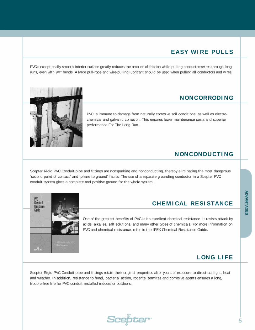
NONCORRODING
NONCONDUCTING
CHEMICAL RESISTANCE
PVC’s exceptionally smooth interior surface greatly reduces the amount of friction while pulling conductors/wires through longruns, even with 90° bends. A large pull-rope and wire-pulling lubricant should be used when pulling all conductors and wires.
PVC is immune to damage from naturally corrosive soil conditions, as well as electro-chemical and galvanic corrosion. This ensures lower maintenance costs and superiorperformance For The Long Run.
Scepter Rigid PVC Conduit pipe and fittings are nonsparking and nonconducting, thereby eliminating the most dangerous‘second point of contact’ and ‘phase to ground’ faults. The use of a separate grounding conductor in a Scepter PVCconduit system gives a complete and positive ground for the whole system.
One of the greatest benefits of PVC is its excellent chemical resistance. It resists attack byacids, alkalies, salt solutions, and many other types of chemicals. For more information onPVC and chemical resistance, refer to the IPEX Chemical Resistance Guide.
LONG LIFE
Scepter Rigid PVC Conduit pipe and fittings retain their original properties after years of exposure to direct sunlight, heatand weather. In addition, resistance to fungi, bacterial action, rodents, termites and corrosive agents ensures a long,trouble-free life for PVC conduit installed indoors or outdoors.
AD
VA
NTA
GE
S

AD
VA
NTA
GE
S
ADVANTAGES CONT’D
6
FIRE RESISTANT
CONCRETE TIGHT
SUITABLE FOR DIRECT BURIAL
IPEX’s PVC compound used to manufacture Scepter products is a self-extinguishingmaterial and will not support combustion. It will not drip or run when exposed to fire.Samples taken from an actual fire show the outer surface of the conduit was blisteredand charred. The interior of the conduit, however, was unaffected. Additionally, theundamaged conductors were then removed and reinstalled in new conduit. Fire-resistant characteristics when tested to CAN ULC S102.2 are as follows:
Scepter Rigid PVC Conduit pipe and fittings are designed and engineered to beconcrete tight in all weather conditions.
PVC is suitable for direct burial and requires no extra protection when installed in accordance with the National ElectricalCode, and the local inspection authority guidelines. The usual care regarding trenches and backfilling should be respected.
IPEX Flame Smoke Fuel
Compound Spread Developed Contribution
1/8" thickness 10 - 20 225 - 270 0
3/4" thickness 10 - 20 300 - 390 0

AD
VA
NTA
GE
S
7
ONE-SOURCE SPECIFICATION
QUALITY CONTROL
IPEX offers a full range of PVC fittings and accessories. As a result, one-material specifying is possible.
In addition to our rigorous quality control testing, IPEX electrical products carry third-party certification by CSA, UL,and NRTL.

INSTALLATION
8
Nominal Conduit Diameter
inches
1/2
3/4
1
1-1/4
1-1/2
2
2-1/2
3
3-1/2
4
5
6
National Electrical Code Max. Support Spacing
feet
3
3
3
5
5
5
6
6
7
7
7
8
SUPPORT
SUPPORT SPACING
Due to PVC’s lightweight, support spacing is different than that used withmetal conduits. Supporting straps should NOT be firmly tightened, to allowfor linear movement. The maximum allowable support spacing, per theNational Electrical Code Article 352.30 (B) is as follows:
MAX OPERATING TEMPERATURE
The National Electrical Code (NEC) allows the use of rigid nonmetallic conduit (RNC)and fittings in locations where ambient temperatures are not in excess of 122°F.
The Canadian Electrical Code (CEC) allows the use of Scepter Rigid PVC Conduit upto a maximum ambient temperature of 167°F.
INS
TAL
LA
TIO
N
CUTTING
Scepter Rigid PVC Conduit can be easily cut on the jobsite by using a hacksaw, carpenter’s saw or PVC conduit cutters. Forlarger sizes of conduit, the use of a mitre box is also recommended to ensure a square cut.
INS
TAL
LA
TIO
N
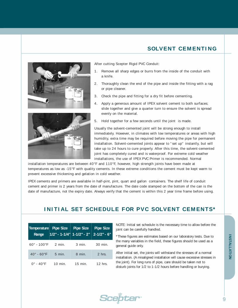
SOLVENT CEMENTING
After cutting Scepter Rigid PVC Conduit:
1. Remove all sharp edges or burrs from the inside of the conduit with a knife.
2. Thoroughly clean the end of the pipe and inside the fitting with a rag or pipe cleaner.
3. Check the pipe and fitting for a dry fit before cementing.
4. Apply a generous amount of IPEX solvent cement to both surfaces; slide together and give a quarter turn to ensure the solvent is spread evenly on the material.
5. Hold together for a few seconds until the joint is made.
Usually the solvent-cemented joint will be strong enough to installimmediately. However, in climates with low temperatures or areas with highhumidity, extra time may be required before moving the pipe for permanentinstallation. Solvent-cemented joints appear to “set up” instantly, but willtake up to 24 hours to cure properly. After this time, the solvent-cementedjoint has completely cured and is waterproof. For extreme cold weatherinstallations, the use of IPEX PVC Primer is recommended. Normal
installation temperatures are between 40°F and 110°F, however, high strength joints have been made attemperatures as low as -15°F with quality cements. In these extreme conditions the cement must be kept warm toprevent excessive thickening and gelation in cold weather.
IPEX cements and primers are available in half-pint, pint, quart and gallon containers. The shelf life of conduitcement and primer is 2 years from the date of manufacture. The date code stamped on the bottom of the can is thedate of manufacture, not the expiry date. Always verify that the cement is within this 2 year time frame before using.
INITIAL SET SCHEDULE FOR PVC SOLVENT CEMENTS*
NOTE: Initial set schedule is the necessary time to allow before thejoint can be carefully handled.
*These figures are estimates based on our laboratory tests. Due tothe many variables in the field, these figures should be used as ageneral guide only.
After initial set, the joints will withstand the stresses of a normalinstallation. (A misaligned installation will cause excessive stresses inthe joint). For long runs of pipe, care should be taken not todisturb joints for 1/2 to 1-1/2 hours before handling or burying.
Temperature
Range
Pipe Size
1/2" - 1-1/4"
Pipe Size
1-1/2" - 2"
Pipe Size
2-1/2" - 6"
60° - 100°F 2 min. 3 min. 30 min.
40° - 60°F 5 min. 8 min. 2 hrs.
0° - 40°F 10 min. 15 min. 12 hrs.
9

INSTALLATION CONT’DIN
STA
LL
AT
ION
10
AVERAGE # OF JOINTS PER PINT OR QUART OF CEMENT
Pipe Size # of Joints # of Joints Pipe Size # of Joints # of Joints(inches) per Pint per Quart (inches) per Pint per Quart
1/2 350 700 2-1/2 40 80
3/4 200 400 3 35 70
1 150 300 1-1/2 30 60
1-1/4 110 220 4 24 48
1-1/2 80 160 5 10 20
2 45 90 6 8 16
BENDING
PVC is a thermoplastic material that, when heated, becomes soft andpliable. As a result, its shape can be altered.
A flameless heat source is recommended to heat the pipe. AN OPENFLAME SHOULD NOT BE USED. An electric unit or an infra-red propaneunit is recommended for heating the pipe.
The necessary temperature for bending Scepter Rigid PVC pipe is 260°F.The pipe must be heated evenly over an area approximately ten times thediameter of the pipe before any attempt at bending is made. Bending thepipe when it has not been thoroughly heated will cause the pipe to “kink.”With proper care and a little practice, the bend will form easily.
Cooling the pipe with cold air or water will cause “spring back.” Allow a fewextra degrees of overbending to compensate for this phenomenon. Themaximum bending radius shall be six times the internal diameter accordingto the National Electrical Code.
IPEX offers a large selection of Scepter Rigid PVC Schedule 40 and Schedule80 bends.
Available in plain end or one end belled, Scepter bends are readily available instandard radius or special radius configuration (18", 24", 30", 36" 48").
Scepter special radius bends are available on request in almost any degree ofbend and radius of bend as a special order.

EX
PAN
SIO
N &
CO
NT
RA
CT
ION
11
USING EXPANSION JOINTS
It is equally important to know when to install an expansion joint as it is to know how to correctly install the expansionjoint. Expansion joints are required when the temperature change is greater than 25°F. Scepter Rigid PVC Conduit has acoefficient of linear expansion of 3.6 x 10⁻⁴ in./ft./°F. Generally, a 100 ft. run of PVC conduit will undergo a change inlength of 3.6 inches for every 100°F temperature change.
For conduit installed indoors, the range of expansion and contraction can be calculated using the maximum air temperatureplus the heat contributed by the conductors inside the conduit and the minimum air temperature expected. Expansion jointsare not required indoors unless there are widely varying temperatures such as the attic of a building.
Conduit installed outdoors, exposed to direct sunlight, will be considerably hotter than the air temperature. As aguideline in this case, add 27°F to the temperature change. Expansion joints should be installed to allow for allanticipated temperature changes.
EXPANSION FORMULA
By using the following formula and the chart below, the total expected expansion in a run can be easily determined:
°F Total Expansion (in.) = length of run (ft.) x temperature change (°F) x 0.00036
0 1 2 3 4 5
120
110
100
90
80
70
60
50
40
30
20
10
PVC PIPE
As a general rulefor every
temperaturechange of 10ºF,
PVC pipe willexpand or contract
3/8" per 100'TE
MP
ER
ATU
RE
CH
AN
GE
IN
ºF
LENGTH VARIATION in/100 ft OF PIPE
PVC PIPE LENGTH VARIATIONDUE TO TEMPERATURE CHANGE (ºF)Coefficient = 3.6 x 10⁻⁴ in/ft/ºF

INSTALLATION CONT’DE
XPA
NS
ION
& C
ON
TR
AC
TIO
N
12
NUMBER OF EXPANSION JOINTS REQUIRED
Use the following equation to determine the number of expansion joints needed for a Scepter Rigid PVC Conduitinstallation:
Number of joints = total expansion (in)
4"
Always round up to the next whole number.
SETTING THE PISTON OPENING
The expansion joint must be installed to allow for expansion and contraction of the conduit run. On a cold day, if anexpansion joint is installed completely closed with the piston bottomed, there is no room for expansion when the conduit iswarmed. If it is installed open to the maximum on a hot day, the expansion joint will pull apart when cooled.
The correct piston opening for any installation condition can be easily determined using the formula below.
Piston setting = max. temperature (°F) – installation temperature (°F) x 4
(inches) total temperature change (°F)
13
INSTALLATION OF EXPANSION JOINTS
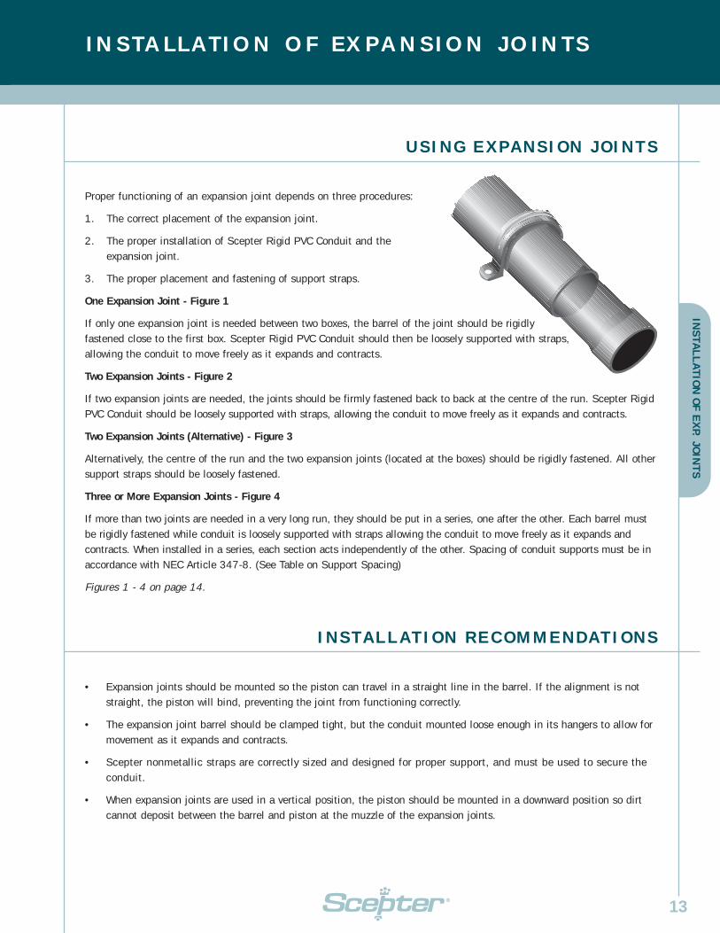
USING EXPANSION JOINTS
Proper functioning of an expansion joint depends on three procedures:
1. The correct placement of the expansion joint.
2. The proper installation of Scepter Rigid PVC Conduit and the expansion joint.
3. The proper placement and fastening of support straps.
One Expansion Joint - Figure 1
If only one expansion joint is needed between two boxes, the barrel of the joint should be rigidlyfastened close to the first box. Scepter Rigid PVC Conduit should then be loosely supported with straps,allowing the conduit to move freely as it expands and contracts.
Two Expansion Joints - Figure 2
If two expansion joints are needed, the joints should be firmly fastened back to back at the centre of the run. Scepter RigidPVC Conduit should be loosely supported with straps, allowing the conduit to move freely as it expands and contracts.
Two Expansion Joints (Alternative) - Figure 3
Alternatively, the centre of the run and the two expansion joints (located at the boxes) should be rigidly fastened. All othersupport straps should be loosely fastened.
Three or More Expansion Joints - Figure 4
If more than two joints are needed in a very long run, they should be put in a series, one after the other. Each barrel mustbe rigidly fastened while conduit is loosely supported with straps allowing the conduit to move freely as it expands andcontracts. When installed in a series, each section acts independently of the other. Spacing of conduit supports must be inaccordance with NEC Article 347-8. (See Table on Support Spacing)
Figures 1 - 4 on page 14.
INSTALLATION RECOMMENDATIONS
• Expansion joints should be mounted so the piston can travel in a straight line in the barrel. If the alignment is notstraight, the piston will bind, preventing the joint from functioning correctly.
• The expansion joint barrel should be clamped tight, but the conduit mounted loose enough in its hangers to allow formovement as it expands and contracts.
• Scepter nonmetallic straps are correctly sized and designed for proper support, and must be used to secure theconduit.
• When expansion joints are used in a vertical position, the piston should be mounted in a downward position so dirtcannot deposit between the barrel and piston at the muzzle of the expansion joints.
INS
TAL
LA
TIO
N O
F E
XP. JO
INT
S

INSTALLATION OF EXPANSION JOINTS CONT'DIN
STA
LL
AT
ION
OF
EX
P. J
OIN
TS
14
Three common mistakes are:
1. Forgetting to use expansion joints.
2. Not using enough expansion joints.
3. Overtightening of support straps.
It is more cost effective to use more expansion joints than needed, rather than too few. It is difficult to correct the problemafter conductors are installed and in service. Failure to accommodate expansion/contraction may result in pipe fracture.
COMMON MISTAKES
Figure 1
Figure 2
Figure 3
Figure 4

STANDARDS AND SAMPLE SPECIFICATIONS
LISTINGS
Scepter Rigid PVC Conduit conforms to thesestandards:
CSA C22.2 No. 211.2, CSA C22.2 No. 211.0
UL Listed - UL651Sunlight ResistantRated for use with 90°C conductors
NEMA TC2Corps. of Engineers Spec. CE 303:01Military Spec, Federal Spec. WC 1094A
Scepter Rigid PVC boxes and fittings conform to these standards:
C22.2 No. 85
UL ListedUL514B - UL514C
NRTL/C indicator adjacent to the CSA mark signifies that the product has been evaluated to the applicable ANSI/UL andCSA Standards, for use in the U.S. and Canada.NRTL, Nationally Recognized Testing Laboratory, is a designation granted by the U.S. Occupational Safety and HealthAdministration (OSHA) to laboratories which have been recognized to perform certification to U.S. Standards.
All wiring shall be installed in Rigid PVC conduit and secured to PVC boxes and cabinets by means of proper fittings.All boxes, access fittings and covers shall be furnished with threaded brass inserts, brass screws and PVC gaskets.
Rigid PVC fittings and junction boxes shall be used for all outlets, pull boxes and junction points. All PVC junction boxesshall be NEMA 1, 2, 3, 4, 4X, 6P, 12 and 13 rated and UL Listed for wet locations.
Exposed conduit shall be securely held in place by suitable hangers or straps with the maximum spacing of points forsupports not exceeding those specified in the NEC. Except when embedded in concrete, rigid conduit pipe shall not beclamped tightly. It shall be supported in such a manner as to permit adequate linear movement, allowing for expansionand contraction of conduit due to temperature change. Where a temperature change exceeding 25°F is anticipated,or alength is expected to be 1/4" or greater in a straight line between securely mounted items, rigid PVC expansion joints shallbe installed in accordance with the manufacturer’s recommendations.
Proper care shall be taken when field bending, to maintain the internal diameter and wall thickness of the conduit.
The contractor shall furnish and install Scepter Rigid PVC conduit pipe and fittings made by IPEX. Where the engineer’sspecifications indicate Scepter products or equivalent, the equivalent shall be UL certified and accepted by the NationalElectrical Code. Due to broad manufacturing tolerances, all pipe and fitting products shall be of the same manufacturer.
SAMPLE SHORT FORM SPECIFICATIONS
National Electrical Code, NEC 1999 Article 347, NEC 2002 Article 352
Canadian Electrical Code, Part 1. Rules 12-1100 – 12-1122
APPROVALS
15
STA
ND
AR
DS
& S
PE
CIF
ICA
TIO
NS

16
CONDUIT DIMENSIONSR
IGID
CO
ND
UIT
DIM
EN
SIO
NS
R IGID SCHEDULE 40 PVC CONDUIT
Schedule 40 Heavy Wall in 10' or 20' Lengths
Nominal Size 10' Product 20' Product O.D. I.D. Min. Wall Weight Standard 10'inches Code Code inches inches inches lbs./100 ft./crate
1/2 032405 032406 0.840 0.622 0.109 15 6,000
3/4 032407 032408 1.050 0.824 0.113 21 4,400
1 032410 032411 1.315 1.049 0.133 31 3,600
1-1/4 032412 032414 1.660 1.380 0.140 42 3,300
1-1/2 032415 032416 1.900 1.610 0.145 53 2,250
2 032420 032421 2.375 2.067 0.154 71 1,400
2-1/2 032425 032426 2.875 2.469 0.203 112 930
3 032430 032431 3.500 3.068 0.216 166 880
3-1/2 032435 032436 4.000 3.548 0.226 200 630
4 032440 032441 4.500 4.026 0.237 236 570
5 032450 032451 5.563 5.047 0.258 321 380
6 032460 032461 6.625 6.065 0.280 417 260
Scepter Rigid Heavy Wall Conduit is listed with Underwriters Laboratories Inc. Installation is covered in the 2002 NationalElectrical Code Article 352, for use above and below ground encased in concrete, direct burial, exposed and concealed spaces.
• UL Listed
• NEMA TC2
• Military Specification - WC1094A
• Federal Specification - WC1094A
• Corp. of Engineers Specification - CE 303:01
• Sunlight Resistant
• Rated for use with 90°conductors

17
RIG
ID C
ON
DU
IT D
IME
NS
ION
S
R IGID SCHEDULE 80 PVC CONDUIT
Nominal Size Sch 40 PVC Sch 80 PVC Aluminum Rigid Steelinches inches inches inches inches
1/2 15 21 28 79
3/4 21 28 27 105
1 31 41 53 153
1-1/4 42 57 70 201
1-1/2 53 70 86 249
2 71 96 116 334
2-1/2 112 146 183 527
3 166 195 239 690
3-1/2 200 - 288 831
4 236 286 340 982
5 321 397 465 1334
6 417 546 613 1771
WEIGHT COMPARISON OF RIGID PVC CONDUIT
Schedule 80 Extra Heavy Wall in 10' or 20' Lengths
Nominal Size 10' Product 20' Product O.D. I.D. Min. Wall Weight Standard 10'inches Code Code inches inches inches lbs./100 ft./crate
1/2 032505 032506 0.840 0.546 0.147 21 6,000
3/4 032507 032508 1.050 0.724 0.154 28 4,400
1 032510 032511 1.315 0.957 0.179 41 3,600
1-1/4 032512 032514 1.660 1.278 0.191 57 3,300
1-1/2 032515 032516 1.900 1.500 0.200 70 2,250
2 032520 032521 2.375 1.939 0.218 96 1,400
2-1/2 032525 032526 2.875 2.323 0.276 146 930
3 032530 032531 3.500 2.900 0.300 195 880
4 032540 032541 4.500 3.826 0.337 286 570
5 032550 032551 5.563 4.813 0.375 397 380
6 032560 032561 6.625 5.761 0.432 546 260
Scepter Rigid Extra Heavy Wall Conduit is for use above ground where subject to severe physical abuse, pole risers, bridgecrossings and other similar conditions.

18
COUPLINGSC
ON
DU
IT F
ITT
ING
S
COUPLINGS
Size Part Product A B C(inches) Number Code (inches) (inches) (inches)
1/2 EC10 068000 1.060 0.844 1.400
3/4 EC15 068001 1.310 1.056 1.640
1 EC20 077003 1.590 1.315 2.031
1-1/4 EC25 077004 2.000 1.660 2.156
1-1/2 EC30 077005 2.230 1.900 2.281
2 EC35 077006 2.720 2.375 2.406
2-1/2 EC40 077007 3.320 2.875 3.187
3 EC45 077008 4.000 3.500 3.437
3-1/2 EC50 077009 4.500 4.000 3.625
4 EC55 077010 5.000 4.500 3.750
5 EC60 077011 6.120 5.563 4.187
6 EC65 077012 7.370 6.625 4.562
5º COUPLINGS
Size Part Product L(inches) Number Code (inches)
2 5EC35 077100 4.0
2-1/2 5EC40 077101 5.5
3 5EC45 077103 6.0
3-1/2 5EC50 077102 7.0
4 5EC55 077104 7.0
5 5EC60 077105 7.5
6 5EC65 077106 11.0

CO
ND
UIT
FIT
TIN
GS
19
LONG LINE COUPLINGS
Size Part Product A(inches) Number Code (inches)
1-1/2 LLC30 077192 3.175
2 LLC35 077193 3.675
2-1/2 LLC40 077194 4.280
3 LLC45 077195 4.800
4 LLC55 077196 6.200
5 LLC60 077197 8.220
6 LLC65 077198 8.220
REPAIR COUPLING SLEEVE
Size Part Product A D Min D Max(inches) Number Code (inches) (inches) (inches)
1-1/2 REC30 077292 2.300 1.912 1.924
2 REC35 077293 2.405 2.367 2.399
2-1/2 REC40 077294 3.450 2.883 2.897
3 REC45 077295 3.600 3.507 3.523
4 REC55 077296 3.920 4.506 4.524
5 REC60 077297 4.275 5.583 5.603
6 REC65 077298 4.620 6.647 6.669
D
A
Size Part Product L(inches) Number Code (inches)
2 x 1-1/4 SW3525 077320 4
3 x 2 SW4535 077321 6
3 x 2-1/2 SW4540 077335 6.5
4 x 2 SW5535 077322 7
4 x 2-1/2 SW5540 069282 -
4 x 3 SW5545 077333 7
(Socket x Socket) Other sizes available upon request.
L
FABRICATED SWEDGE REDUCER COUPLINGS

CO
ND
UIT
FIT
TIN
GS
20
ADAPTERS
TERMINAL ADAPTERS1/2" - 1-1/4" Tapered Thread; 1-1/2" - 6" Non-Tapered Thread
Size Part Product A B C D(inches) Number Code (inches) (inches) (inches) (inches)
1/2 TA10 077021 0.700 0.591 0.750 1.550
3/4 TA15 077022 0.675 0.790 1.000 1.750
1 TA20 077023 0.625 1.000 1.115 1.860
1-1/4 TA25 077024 0.640 1.311 1.300 2.125
1-1/2 TA30 077025 0.725 1.530 1.425 2.250
2 TA35 077026 0.800 1.970 1.150 2.100
2-1/2 TA40 077027 0.800 2.346 1.900 2.930
3 TA45 077028 0.815 2.915 2.000 3.055
3-1/2 TA50 077029 1.000 3.385 1.715 3.055
4 TA55 077030 0.815 3.850 1.990 3.215
5 TA60 077031 1.725 5.015 2.000 5.985
6 TA65 077032 1.875 6.025 2.130 6.500
FEMALE ADAPTERSNPT Tapered Thread
Size Part Product A B C D(inches) Number Code (inches) (inches) (inches) (inches)
1/2 FA10 077041 0.800 0.620 0.825 1.725
3/4 FA15 077042 0.800 0.820 1.000 1.900
1 FA20 077043 1.000 1.065 1.200 2.300
1-1/4 FA25 077044 1.015 1.395 1.300 2.425
1-1/2 FA30 077045 1.050 1.575 1.290 2.440
2 FA35 077046 1.075 2.050 1.375 2.550
2-1/2 FA40 077047 1.675 2.470 1.985 3.760
3 FA45 077048 1.630 3.090 2.150 4.100
3-1/2 FA50 077049 1.800 3.540 2.000 3.985
4 FA55 077050 1.755 4.025 2.185 4.210
5 FA60 077051 2.065 5.035 3.000 5.240
6 FA65 077052 2.065 6.045 3.000 5.235
AC
D
B
CO
ND
UIT
FIT
TIN
GS
21
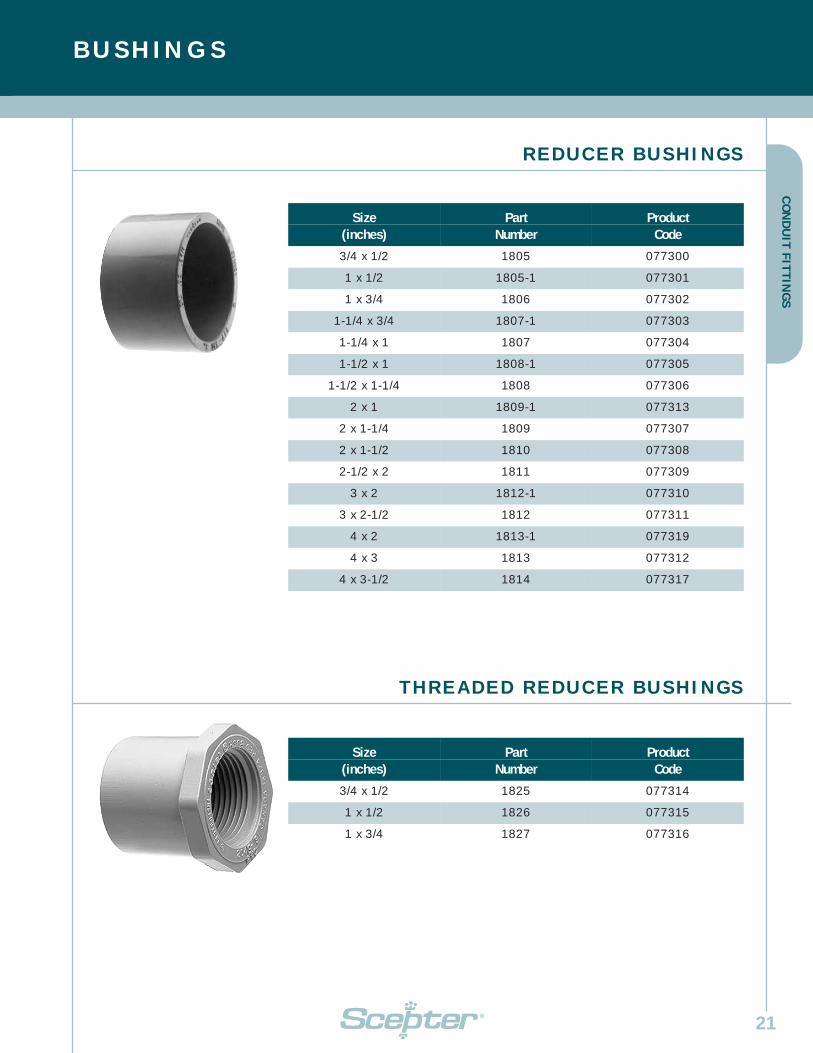
REDUCER BUSHINGS
Size Part Product(inches) Number Code
3/4 x 1/2 1805 077300
1 x 1/2 1805-1 077301
1 x 3/4 1806 077302
1-1/4 x 3/4 1807-1 077303
1-1/4 x 1 1807 077304
1-1/2 x 1 1808-1 077305
1-1/2 x 1-1/4 1808 077306
2 x 1 1809-1 077313
2 x 1-1/4 1809 077307
2 x 1-1/2 1810 077308
2-1/2 x 2 1811 077309
3 x 2 1812-1 077310
3 x 2-1/2 1812 077311
4 x 2 1813-1 077319
4 x 3 1813 077312
4 x 3-1/2 1814 077317
THREADED REDUCER BUSHINGS
Size Part Product(inches) Number Code
3/4 x 1/2 1825 077314
1 x 1/2 1826 077315
1 x 3/4 1827 077316
BUSHINGS

CO
ND
UIT
FIT
TIN
GS
22
END BELLS
END BELLS & CAPS
END CAPS
Size Part Product(inches) Number Code
1/2 CAP10 077421
3/4 CAP15 077422
1 CAP20 077423
1-1/4 CAP25 077424
1-1/2 CAP30 077425
2 CAP35 077426
2-1/2 CAP40 077427
3 CAP45 077428
3-1/2 CAP50 077429
4 CAP55 077430
5 CAP60 077431
6 CAP65 077432
Size Part Product(inches) Number Code
1/2 EB-10 077406
3/4 EB-15 077085
1 EB-20 077323
1-1/4 EB-25 077324
1-1/2 EB-30 077325
2 EB-35 077326
2-1/2 EB-40 077327
3 EB-45 077328
3-1/2 EB-50 077329
4 EB-55 077330
5 EB-60 077331
6 EB-65 077332

23
Size Part Product A (in.) B (in.) Travel(inches) Number Code max. min. (inches)
1/2 EJ10 077381 12.00 8.00 4
3/4 EJ15 077382 12.00 8.00 4
1 EJ20 077383 12.50 8.50 4
1-1/4 EJ25 077384 13.00 9.00 4
1-1/2 EJ30 077385 13.00 9.00 4
2 EJ35 077386 13.25 9.25 4
2-1/2 EJ40 077387 13.25 9.25 4
3 EJ45 077388 22.25 14.25 8
3-1/2 EJ50 077389 22.25 14.25 8
4 EJ55 077390 22.25 14.25 8
5 EJ60 077391 22.25 14.25 8
6 EJ65 077392 22.25 14.25 8
“O” RING EXPANSION JOINTS
Amax.
Bmin.
CO
ND
UIT
FIT
TIN
GS
POLY PLUGS
Size Part Product(inches) Number Code
2 - 2-1/2 PP3540 077433
3 - 3-1/2 PP4550 077434
4 PP55 077435
5 PP60 077436
6 PP65 077437
POLY PLUGS & EXPANSION JOINTS

CO
ND
UIT
FIT
TIN
GS
24
Size Part Description Product(inches) Number Code
2 SE-J-35 Complete Assembly 077889
3 SE-J-45 Complete Assembly 077890
4 SE-J-55 Complete Assembly 077891
EXPANSION JOINTS
TA SPECIAL EXPANSION JOINT
Size Part Product(inches) Number Code
2-1/2 EJ40TA 077398
Size Part Product(inches) Number Code
1/2 OPEJ10 077018
3/4 OPEJ15 077019
1 OPEJ20 077053
1-1/4 OPEJ25 077054
1-1/2 OPEJ30 077061
2 OPEJ35 077063
ONE-PIECE EXPANSION COUPLING
The National Electrical Code requires the use of expansion fittings for RNC to compensate for thermal expansion &contraction. For more information consult the NEC 2002 Article 352.44 and review the expansion and contractioninformation on pages 11, 12 and 13 of this brochure.
EXPANSION & DEFLECTION FITTING ASSEMBLIES

CO
ND
UIT
FIT
TIN
GS
25
Size Pro/code Pro/code D T R (inches) Bell End Plain End (inches) (inches) (inches)
1/2 068420 068580 0.840 1.500 4.00
3/4 068421 068581 1.050 1.500 4.50
1 068422 068582 1.315 1.875 5.75
1-1/4 068423 068583 1.660 2.000 7.25
1-1/2 068424 068584 1.900 2.000 8.25
2 068425 056858 2.375 2.000 9.50
2-1/2 068426 068586 2.875 3.000 10.50
3 068427 068587 3.500 3.125 13.00
3-1/2 068428 068588 4.000 3.250 15.00
4 068429 068589 4.500 3.375 16.00
5 068430 068591 5.563 3.625 24.00
6 068431 068592 6.625 3.750 36.00
UL 90º ELBOWS
TR
D
ELBOWS
UL SPECIAL RADIUS 90º ELBOWSc/w Solvent Bell End
Size Part Product D T R(inches) Number Code (inches) (inches) (inches)
2 NSL 2-24 068725 2.375 2.000 24.00
2 NSL 2-36 068765 2.375 2.000 36.00
3 NSL 3-24 068727 3.500 3.125 24.00
3 NSL 3-36 068767 3.500 3.125 36.00
4 NSL 4-36 068769 4.500 3.375 36.00
4 NSL 4-48 068789 4.500 3.375 48.00
5 NSL 5-36 068771 5.563 3.625 36.00
6 NSL 6-36 068772 6.625 3.370 36.00
Note: Other sizes are available and in stock. Consult your IPEX price list.
D
T
R

CO
ND
UIT
FIT
TIN
GS
26
UL 45º ELBOWS
Size Pro/code Pro/code D T R(inches) Bell End Plain End (inches) (inches) (inches)
1/2 068561 068600 0.840 1.500 4.00
3/4 068562 068601 1.050 1.500 4.50
1 068563 068602 1.315 1.875 5.75
1-1/4 068564 068603 1.660 2.000 7.25
1-1/2 068565 068604 1.900 2.000 8.25
2 068566 068605 2.375 2.000 9.50
2-1/2 068567 068606 2.875 3.000 10.50
3 068568 068607 3.500 3.125 13.00
3-1/2 068569 068608 4.000 3.250 15.00
4 068570 068609 4.500 3.375 16.00
5 068571 068611 5.563 3.625 24.00
6 068572 068612 6.625 3.750 30.00
ELBOWS CONT’D
UL 30º ELBOWSPlain End x Plain End
Size Part Product D T R(inches) Number Code (inches) (inches) (inches)
1/2 EE1030 068620 0.840 1.500 4.00
3/4 EE1530 068621 1.050 1.500 4.50
1 EE2030 068622 1.315 1.875 5.75
1-1/4 EE2530 068623 1.660 2.000 7.25
1-1/2 EE3030 068624 1.900 2.000 8.25
2 EE3530 068625 2.375 2.000 9.50
2-1/2 EE4030 068626 2.750 3.000 10.50
3 EE4530 068627 3.500 3.125 13.00
3-1/2 EE5030 068628 4.000 3.250 15.00
4 EE5530 068629 4.500 3.375 16.00
5 EE6030 068631 5.563 3.625 24.00
6 EE6530 068632 6.625 3.750 30.00
D
T
R

CO
ND
UIT
FIT
TIN
GS
27
PIPE STRAPS
PIPE STRAPS POLYETHYLENE (PE)2 Hole
Size Part Product(inches) Number Code
2-1/2 PS40 077262
3 PS45 077263
4 PS55 077264
PIPE STRAPS COATED STEEL2 Hole
Size Part Product(inches) Number Code
2 CS35 077818
2-1/2 CS40 077819
3 CS45 077820
3-1/2 CS50 077821
4 CS55 077822
5 CS60 077824
6 CS65 077823
PIPE STRAPS PVC2 Hole
Size Part Product(inches) Number Code
1/2 PS10 077811
3/4 PS15 077812
1 PS20 077813
1-1/4 PS25 077814
1-1/2 PS30 077815
2 PS35 077816

CO
ND
UIT
FIT
TIN
GS
28
PIPE STRAPS COATED STEEL1 Hole
Size Part Product(inches) Number Code
1/2 CS10-1 077831
3/4 CS15-1 077832
1 CS20-1 077833
1-1/4 CS25-1 077834
1-1/2 CS30-1 077835
2 CS35-1 077836
2-1/2 CS40-1 077837
3 CS45-1 077838
3-1/2 CS50-1 077839
4 CS55-1 077840
STRAPS, CLAMPS & WALL SPACERS
NONMETALLIC CONDUIT CLAMPS & WALL SPACERS
Size Part Product X Y Z(inches) Number Code (inches) (inches (inches)
1/2 CCS10 077794 1.191 2.414 1.824
3/4 CCS15 077796 1.195 2.660 2.106
1 CCS20 077797 1.215 2.962 2.443
1-1/4 CCS25 077798 1.182 3.300 2.855
1-1/2 CCS30 077799 1.193 3.600 3.170
2 CCS35 077800 1.195 4.135 3.785
Base CCS-B 077343 - - -
Note: CCS-B are sold individually, two pieces are required to create one base unit.

CO
ND
UIT
FIT
TIN
GS
29
ACCESS FITTINGS* TYPE LR
Hub Size Part Product (inches) Number Code
1/2 SLR10S 077481
3/4 SLR20S 077482
1 SLR30S 077483
1-1/4 SLR40S 077484
1-1/2 SLR50S 077485
2 SLR60S 077486
2-1/2 SLR70S 077480
3 SLR80S 077488
3-1/2 SLR90S 077487
4 SLR100S 077489
ACCESS FITTINGS* TYPE LB
Hub Size Part Product(inches) Number Code
1/2 SLB10S 077541
3/4 SLB20S 077542
1 SLB30S 077543
1-1/4 SLB40S 077544
1-1/2 SLB50S 077545
2 SLB60S 077546
2-1/2 SLB70S 077547
3 SLB80S 077548
3-1/2 SLB90S 077549
4 SLB100S 077550
* All access fittings are CSA certified and all access fittings except Type TB are UL listed for wet locations. Supplied with threaded brass inserts, combination brass head screws and PVC gasketing.
* Stainless steel screws are available upon request.
ACCESS FITTINGS

CO
ND
UIT
FIT
TIN
GS
30
ACCESS FITTINGS* TYPE LL
Hub Size Part Product(inches) Number Code
1/2 SLL10S 077521
3/4 SLL20S 077522
1 SLL30S 077523
1-1/4 SLL40S 077524
1-1/2 SLL50S 077525
2 SLL60S 077526
2-1/2 SLL70S 077527
3 SLL80S 077528
3-1/2 SLL90S 077530
4 SLL100S 077529
* All access fittings are CSA certified and all access fittings except Type TB are UL listed for wet locations. Supplied with threaded brass inserts, combination brass head screws and PVC gasketing.
* Stainless steel screws are available upon request.
ACCESS FITTINGS CONT’D
ACCESS FITTINGS* TYPE T
Hub Size Part Product(inches) Number Code
1/2 ST10S 077461
3/4 ST20S 077462
1 ST30S 077463
1-1/4 ST40S 077464
1-1/2 ST50S 077465
2 ST60S 077466
2-1/2 ST70S 077467
3 ST80S 077468
3-1/2 ST90S 077571
4 ST100S 077572

CO
ND
UIT
FIT
TIN
GS
31
ACCESS FITTINGS* TYPE E
Hub Size Part Product(inches) Number Code
1/2 SE10S 077561
3/4 SE20S 077562
1 SE30S 077563
1-1/4 SE40S 077564
1-1/2 SE50S 077565
2 SE60S 077566
2-1/2 SE70S 077567
3 SE80S 077568
3-1/2 SE90S 077569
4 SE100S 077570
ACCESS FITTINGS* TYPE C
Hub Size Part Product(inches) Number Code
1/2 SC10S 077501
3/4 SC20S 077502
1 SC30S 077503
1-1/4 SC40S 077504
1-1/2 SC50S 077505
2 SC60S 077506
2-1/2 SC70S 077507
3 SC80S 077508
3-1/2 SC90S 077510
4 SC100S 077509
* All access fittings are CSA certified and all access fittings except Type TB are UL listed for wet locations. Supplied with threaded brass inserts, combination brass head screws and PVC gasketing.
* Stainless steel screws are available upon request.

CO
ND
UIT
FIT
TIN
GS
32
ACCESS FITTINGS* TYPE TB
* All access fittings are CSA certified and all access fittings except Type TB are UL listed for wet locations. Supplied with threaded brass inserts, combination brass head screws and PVC gasketing.
* Stainless steel screws are available upon request.
Hub Size Part Product(inches) Number Code
1/2 STB10S 077451
3/4 STB20S 077452
1 STB30S 077453
1-1/4 STB40S 077454
1-1/2 STB50S 077455
2 STB60S 077456
Size A B C D E F(inches) (inches) (inches) (inches) (inches) (inches) (inches)
1/2 5.606 0.639 1.268 1.100 0.840 4.337
3/4 5.606 0.810 1.536 1.325 1.050 5.395
1 6.500 0.910 1.700 1.100 1.335 6.250
1-1/4 7.900 1.050 2.300 2.250 1.660 7.625
1-1/2 8.500 1.125 2.675 2.250 1.900 8.250
2 10.875 1.160 3.188 2.820 2.375 10.531
2-1/2 14.600 1.750 4.500 3.950 2.870 13.630
3 14.600 1.900 4.500 3.950 3.510 13.630
3-1/2 17.040 2.125 5.536 5.000 4.000 16.000
4 17.040 2.125 5.536 5.000 4.530 16.000
G H I J K L(inches) (inches) (inches) (inches) (inches) (inches)
4.095 1.297 2.487 2.280 1.005 0.750
4.095 1.297 2.487 2.803 1.005 0.810
4.750 1.500 2.075 3.250 1.125 1.115
5.750 1.750 3.575 3.950 1.562 1.300
6.500 1.750 3.938 4.250 1.656 1.425
8.156 2.344 4.535 5.438 1.968 1.160
9.825 3.805 6.240 7.300 2.610 -
10.897 2.733 6.240 7.300 2.610 -
11.465 4.535 7.500 8.535 2.975 -
11.465 4.535 7.500 8.535 2.975 -
B
DE
B
C
JJ
K LI
ACCESS FITTING DIMENSIONS
ACCESS FITTINGS CONT’D

CO
ND
UIT
FIT
TIN
GS
33
SERVICE ENTRANCE FITTINGS
Size Part Product(inches) Number Code
1/2 EF10 077281
3/4 EF15 077282
1 EF20 077283
1-1/4 EF25 077284
1-1/2 EF30 077285
2 EF35 077286
2-1/2 EF40 077287
3 EF45 077288
3-1/2 EF50 077289
4 EF55 077290
SERVICE ENTRANCE FITTINGS & METER OFFSETS
Size Part Product(inches) Number Code
1-1/4 MO25 077941
2 MO35 077942
METER OFFSETS
LONG METER OFFSETSFabricated
Size Part Product A B(inches) Number Code (inches) (offset)
1-1/4 LMO25 069641 12 0.91
1-1/2 LMO30 069645 12 1.61
2 LMO35 069646 14 1.50
A
B

CO
ND
UIT
FIT
TIN
GS
34
The “two in one” access pull elbow reduces inventory costs (3/4" hub fitting suppliedwith 3/4" x 1/2" reducers). This pull elbow is approved for wet locations and providesfor easy wire pulling. It is manufactured from high impact, nonconducting andnoncorroding PVC.
Size Part Product(inches) Number Code
1/2 or 3/4 PE15/10 077491
“TWO IN ONE” PULL ELBOW
SLIP METER RISERS
Size Part Product L A(inches) Number Code (inches) (inches
2 SMR35TA 068371 25.188 23.088
2-1/2 SMR40TA 068372 25.188 22.258
3 SMR45TA 068373 25.188 21.133
4 SMR55TA 068374 25.188 21.973
Schedule 40 Rigid PVC Conduit
Size Part Product
(inches) Number Code
1-1/4 MHU25 077961
1-1/2 MHU30 077963
2 MHU35 077965
2-1/2 MHU40 077967
3 MHU45 077968
METER HUBS
METER HUBS, RISERS & PULL ELBOWS

35
CO
ND
UIT
FIT
TIN
GS
NONMETALLIC THREADED STRAIN RELIEF CONNECTORSc/w “O”Ring, Locknut & 4 Grommets
Size Part Product(inches) Number Code
1/2 TSRCU10 077244
3/4 TSRCU15 077261
SOCKET WELD STRAIN RELIEF CONNECTORc/w 4 Grommets
Size Part Product(inches) Number Code
3/4 SRCU15 077209
GROMMET DIMENSIONS
Scepter’s Nonmetallic StrainRelief Connectors are suppliedwith all the components youneed for a complete connection.The connector body, a selectionof grommets and compressionrings accepting a range of corddimensions, a sealing ‘O’ ringand metallic locknut are allsupplied in one package.Available in 1/2" and 3/4"threaded hub and 3/4" PVCsocket solvent weldconfigurations to accommodatea variety of applications.
FROM TO(inches) (inches)
Ø = .420 Ø = .515
Ø = .520 Ø = .615
FROM TO(inches) (inches)
Ø = .240 Ø = .315
Ø = .320 Ø = .415
STRAIN RELIEF CONNECTORS

36
CO
ND
UIT
FIT
TIN
GS
LIGHT FIXTURES
LVPE 15/10 LVPE150-PCC
LVPUG 150* Approved for use with 60W MAX Type A lamp.
Description Part Hub Product
Fixture c/w Number Code
Clear Glass Globe LVPE 150-10/15 1/2" - 3/4" 077493
Heat Resistant Clear Glass Globe LVPEHRC 150 1/2" - 3/4" 077578
Heat Resistant Red Glass Globe LVPEHRR 150 1/2" - 3/4" 077599
Heat Resistant Blue Glass Globe LVPEHRB 150 1/2" - 3/4" 077579
Heat Resistant Green Glass Globe LVPEHRG 150 1/2" - 3/4" 077597
Heat Resistant Amber Glass Globe LVPEHRA150 1/2" - 3/4" 077598
Replacement Clear Glass Globe LGC 150 - 077247
Nonmetallic Clamp-on Guard LVPUG150 - 077558
Clear Glass Globe & Clamp-on Guard LVPE150-1015 1/2" - 3/4" 077402
Light Fixture with Polycarbonate Globe* LVPE150-PCC 1/2" - 3/4" 077181
Sceptalight is constructed of noncorroding, nonconductive, high impact glass reinforced polyester resin. It features a one-piece fixture base with threaded hub entry offering a 15 cubic inch volume. Sceptalight’s utility fixture is approved for usewith 75°C wiring and rated for use with 150 Watt A21 medium base incandescent lamp. Integral molded mounting feetprovide for easy installation and ensure a secure support.
NONMETALLIC VAPOR-PROOF INCANDESCENT LIGHT FIXTURE

CO
VE
RS
& C
OV
ER
PL
AT
ES
37
Description Part ProductNumber Code
Duplex Receptacle DRC15/10 077617
Toggle Switch TSC15/10 077616
Single Receptacle 20RC15/10 077618
Single Receptacle 20-3RC15/10 077619
Single Receptacle 30-3RC15/10 077620
Blank c/w Gasket BRC15/10 077611
PVC Gasket GASK15/10 077621
F SERIES - SINGLE GANG PLATES
BRC15/1030-3RC15/1020-3RC15/1020RC15/10TSC15/10DRC15/10 GASK15/10
1.415"dia. dia. dia.
1.610" 1.760"
COVERS & COVER PLATES

CO
VE
RS
& C
OV
ER
PL
AT
ES
38
COVERS & COVER PLATES CONT’D
Description Part ProductNumber Code
Blank Cover c/w Gasket BRC20-2-U 077359
Double Switch TSC20-2-U 077373
Double Duplex Receptacle DRC20-2-U 077362
Combo Switch Duplex Receptacle TSDC20-2-U 077374
Foam Gasket with Adhesive GASKF20-2-U 172650
F SERIES - DOUBLE GANG PLATES
F SERIES - TRIPLE GANG PLATES
Description Part ProductNumber Code
Triple Receptacle DRC20-3 077747
Combo Switch Receptacle DSDR20-3 077745
Triple Switch TSC20-3 077744
Combo Switch Receptacle TSDC20-3 077746
Blank Cover c/w Gasket BRC20-3 077748
PVC Gasket GASK20-3 077749
BRC20-2-U TSC20-2-U DRC20-2-U
DRC20-3
BRC20-3GASK20-3 DSDR20-3 TSC20-3 TSDC20-3
TSDC20-2-U GASKF20-2-U

CO
VE
RS
& C
OV
ER
PL
AT
ES
39
SINGLE GANG WEATHERPROOF COVERS
Description Device Part ProductOpening (in) Number Code
Plunger-style Switch Cover VPT15/10 077630
Toggle Switch Cover VSC15/10 077612
Grey Toggle Switch Cover WTG15/10 077606
Grey Duplex Receptacle WDR15/10 077993
White Duplex Receptacle RWDR15/10 077786
Grey Ground Fault Receptacle WGF15/10 077785
White Ground Fault Receptacle RWGF15/10 077787
Single Receptacle Device 15 AMP 1.375 WTL15 077992
Single Receptacle Device 20 AMP 1.625 WTL20 077994
Single Receptacle Device 30 AMP 1.722 WTL30 077991
Single Receptacle Device 50 AMP 2.187 WTL50 077951
Grey Double Door Duplex Receptacle WDRE15/10 077087
White Double Door Duplex Receptacle RWDRE15/10 077408
Gasket for W Series Cover(except WDRE & RWDRE)
GASKW 077755
Gasket for WDRE & RWDRE Covers GASKDD 072225
* Gaskets are included with all weatherproof covers.
VPT15/10
WDR15/10RWDR15/10
WGF15/10RWGF15/10
WTL15WTL20WTL30
WDRE15/10RWDRE15/10
WTL50
VSC15/10
WTG15/10
Weatherproof covers, with lids closed, are UL listed for wet locations.

CO
VE
RS
& C
OV
ER
PL
AT
ES
40
COVERS & COVER PLATES CONT’D
DOUBLE GANG WEATHERPROOF COVERS
* Gaskets are included with all weatherproof covers.
* VSGG20-2 and VSDD20-2 are universal and will fit on most PVC and metal boxes.
Description Part ProductNumber Code
Toggle Switch Cover VSC20-2-U 077376
Combination Switch Cover & GFI Receptacle VSRC20-2-U 077357
Combination Switch Cover & Duplex Receptacle VSDR20-2-U 077356
Combination Switch Cover & Single Receptacle VSRR20-2 077753
Double Door GFCI Cover VSGG20-2 077096
Double Door Duplex Cover VSDD20-2 077097
Gasket for Double Gang(except VSGG20-2 & VSDD20-2)
GASK20-2 077743
Gasket for VSGG20-2 and VSDD20-2 Double Gangs GASKV20-2 072227
VSC20-2-U
VSRC20-2-U
VSRR20-2
VSDD20-2
VSGG20-2
VSDR20-2-U

BO
XE
S
41
BOXES
F SERIES SINGLE GANG BOXES
Outside Dimensions:Length, 4-9/16" - Width, 2-13/16 " - Depth, 2"
Hub Size Part Product Volume(inches) Number Code (in3)
1/2 FSC10 077607 17.0
3/4 FSC15 077608 17.0
1/2 FS10 077601 17.5
3/4 FS15 077602 17.5
1/2 FSCC10 077622 16.3
3/4 FSCC15 077623 16.3
1/2 FSS10 077604 17.0
3/4 FSS15 077605 17.0
Note: 10 = 1/2" Hub, 15 = 3/4" Hub
F SERIES SINGLE GANG DEEP BOXES
Outside Dimensions: Height, 4 9/16" – Width, 2 13/16" – Depth 2 3/4", Cubic Inches = 35.30With the exception of the FD Blank Box, Scepter FD Series Single Gang Deep Boxesare molded with 1" conduit hubs and supplied with reducer bushings. The conduithub(s) are field modified as 1/2", 3/4" or 1" to accommodate job-site requirements.The appropriate quantity of 1" x 3/4" and 3/4" x 1/2" reducers to create the desiredhub size are packaged with each FD Series Single Gang Deep Box.
Hub Size Part Product Volume(inches) Number Code (in3)
1/2, 3/4, 1 FDC101520 077291 26.0
1/2, 3/4, 1 FDS101520 077299 26.8
* BLANK FD BLANK 077603 29.2
347 VOLT FD347 077610 29.2
Note: 10 = 1/2" Hub, 15 = 3/4" Hub, 20 = 1" Hub
* Not UL Listed
FS
FSCC
FSC
FSS
FDC101520
FDS101520
FD Blank
Note: All F Series boxes are supplied with integral mounting feet, threaded brass inserts and grounding clips.

BO
XE
S
42
BOXES CONT’D
F SERIES DOUBLE GANG BOXES
FS-2-U cu.in = 38.5, FSC-2-U & FSS-2-U cu.in. =37.0, FSCC-2-U cu.in. = 35.0, FD-2-U cu.in. = 47.5With the exception of the FD-2 Blank Box, Scepter FSeries Double Gang Boxes are molded with 1" conduithubs and supplied with reducer bushings. The conduithub(s) are field modified as 1/2", 3/4" or 1" toaccommodate job-site requirements. The appropriatequantity of 1" x 3/4" and 3/4" x 1/2" reducers tocreate the desired hub size are packaged with each FSeries Double Gang Box.
Hub Size Part Product OD (inches) Volume(inches) Number Code H W E (in3)
1/2, 3/4, 1 FS-2-101520-U 077364 4.62 4.62 2.5 38.5
1/2, 3/4, 1 FSC-2-101520-U 077368 4.62 4.62 2.5 37.0
1/2, 3/4, 1 FSS-2-101520-U 077372 4.62 4.62 2.5 37.0
1/2, 3/4, 1 FSCC-2-101520-U 077369 4.62 4.62 2.5 35.0
* Blank FD-2-U 077649 4.75 4.75 3.0 47.5
* Not UL Listed
F SERIES TRIPLE GANG BOXES
FSC-3-101520
FS-3-101520
D
FD-3
H W
Note: All F Series boxes are supplied with integral mounting feet, threaded brass inserts and grounding clips or bars.
With the exception of the FD-3 Blank Box, Scepter F Series Triple Gang Boxes aremolded with 1" conduit hubs and supplied with reducer bushings. The conduit hub(s)are field modified as 1/2", 3/4" or 1" to accommodate job-site requirements. Theappropriate quantity of 1" x 3/4" and 3/4" x 1/2" reducers to create the desired hubsize are packaged with each F Series Triple Gang Box.
Hub Size Part Product OD (inches) Volume(inches) Number Code H W D (in3)
1/2, 3/4, 1 FS-3-101520 077337 4.5 6.6 2.5 56.0
1/2, 3/4, 1 FSC-3-101520 077438 4.5 6.6 2.5 54.0
* Blank FD-3 077737 4.5 6.6 3.0 73.8
* Not UL Listed
FD-2-U
FSS-2-101520-U
FSCC-2-101520-U
FS-2-101520-U
FSC-2-101520-U

BO
XE
S
43
OCTAGONAL BOXES*
Octagonal Boxes are shipped complete with cover, gasket, 4 reducing bushings(3/4" x 1/2"), and 4 sealing caps to be installed from inside box to seal off unusedentry hubs.
Size Part Hub Size L H Volume Product(inches) Number (inches) (inches) (inches) (in3) Code4 x 1-1/2 OB15/10 1/2 - 3/4 4 1.680 15.5 077983*
4 x 2-1/8 OB20 1 4 2.250 21.5 077984*
OCTAGONAL BOX EXTENSION RINGS
Size Part Product(inches) Number Code
4 x 1 deep XR20 077989
4 x 2 deep XR35 077990
Note: Octagonal Boxes are not designed for supporting light fixtures.
THREADED JUNCTION BOXES
Size Part Product(inches) Number Code
4 - 3/4" threaded hubs LFB150C 077250
4 - 3/4 threaded hubs c/w1/2" threaded hole in cover
LFB150T 077251
Scepter’s Threaded Junction Boxes are corrosion resistant, non-conductive andincorporate high-temperature silicone gaskets and brass hardware to withstandextreme temperature variations. Manufactured from glass-reinforced thermoplasticpolyester resin, these boxes can endure extreme temperatures (material temperaturerange -40°F to +302°F).
LFB150C
LFB150T

BO
XE
S
44
BOXES CONT’D
PVC MOLDED JUNCTION BOXES
Junction boxes are supplied with threaded brass insert, brass screws, PVC gasketingand mounting feet. Nylon and stainless steel screws, as well as larger sizes offabricated junctions box, are available upon request.(F = Threaded brass insert size.)
Part Product A B C D E F VolumeNumber Code (inches) (inches) (inches) (inches) (inches) (inches) (in.³)
JB442 077659 3.675 4.000 3.450 2.125 2.000 8-32 26.5
JB444 077696 3.675 4.000 3.450 4.188 3.750 8-32 51.5
JB446 077669 3.675 4.000 3.450 6.225 6.000 8-32 78.0
JB552 077670 4.680 5.000 4.485 2.000 1.845 8-32 40.0
JB664 077697 6.000 6.375 5.813 4.188 4.000 10-32 138.0
JB666 077698 6.000 6.375 5.813 6.188 6.000 10-32 211.0
JB884 077664 8.075 8.625 7.966 4.230 4.005 1/4-20 434.0
JB887 077671 8.100 8.625 7.966 7.250 7.035 1/4-20 248.0
JB12124 077672 12.085 12.580 11.874 4.256 4.030 1/4-20 577.4
JB12126 077666 12.085 12.580 11.874 6.240 6.025 1/4-20 846.0
JB12128 077668 12.085 12.580 11.874 8.250 8.025 1/4-20 1102.0
Junction boxes are:
NEMA 1, 2, 3, 4, 4x, 6P, 12, 13 UL listed for wet locations.
Unflanged PVC fabricated boxes of any size may be made to customers’ specificationsand come complete with lids, gaskets and screws.These boxes are not UL Listed and are not returnable.
FABRICATED BOXES
B CA
AF
BC
DE

BO
XE
S
45
FLANGED BOX W FIBER-REINFORCED SAFETY TREAD COVER
Scepter’s Flanged ‘H’ Series Junction Boxes provide H10 Highway Loading. The fiber-reinforced safety tread cover secures using recessed Hex Key fastening hardwareoffering a simple installation while reducing the opportunity for tampering.
Part Product Box ID (inches) Lid Dimensions (inches) VolumeNumber Code L W D A B C (in3)
H664 077685 6 6 4 1/4 9.0 9.0 0.60 138.0
H666 077686 6 6 6 1/4 9.0 9.0 0.60 211.0
H884 077687 8 8 4 1/4 11.5 11.5 0.75 248.0
H886 077688 8 8 6 1/4 11.5 11.5 0.75 434.0
H887 077689 8 8 7 1/4 11.5 11.5 0.75 434.0
H887-A 077692 8 8 7 1/4 11.5 11.5 0.75 434.0
JUNCTION BOX ADAPTERS
Size Part Product(inches) Number Code
1/2 JBA10 077721
3/4 JBA15 077722
1 JBA20 077723
1-1/4 JBA25 077724
1-1/2 JBA30 077725
2 JBA35 077726
2-1/2 JBA40 077727
3 JBA45 077728
3-1/2 JBA50 077729
4 JBA55 077730
C
BA
C
H887
H887-A
Standard PVCCoupling
JunctionBox Adapter

BO
XE
S
46
BOXES CONT’D
NONMETALLIC FLOOR BOX, COVER & METAL COVER ADAPTERInstallation is quick and simple, with our nonmetallic floor box and covers, saving both time and money over similarmetallic assemblies.
Scepter’s floor box and duplex receptacle covers are constructed from high impact, noncorroding and nonconductingPVC. The flush-mount covers are available in custom colors and are shipped with a levelling ring complete with agrounding clip. Metal cover adapter kits are also available, allowing you to adapt to metal floor plates. Our 6" deepfloor box allows flexibility for various concrete floor pours, while our 4-3/4" width offers easy access and ample wireroom. The box comes complete with 2 - 1" and 2 - 3/4" hub openings.
All boxes are shipped complete with reducer plugs for added versatility.
Color Part ProductDescription Number Code
Floor Box Base(includes disposable protective cap andreducer plugs)
FB 076954
Floor Box Base c/w Leveling Ring Adapter(includes disposable protective cap, reducer plugsand leveling ring adapter)
FBKIT 077068
Metal Cover Adapter Kit(includes levelling ring, metal cover adapter and2 gaskets)
AFMC 076953
Universal Leveling Ring Adapter LRA-U 076606
Floor Box Duplex Receptacle Cover (Nonmetallic)(includes flush mount cover, blank cover & gasket)
Brown FBDRCB 076955
Gold FBDRCG 076949
Grey FBDRCGr 076600
Light Almond FBDRCA 076605
Tri-Service Universal Divider Kit(includes upper and lower dividers, riser tube and4 grommets)
FBUDK 077948
Y Connector (3/4") FBYC 077499
FB
AFMC
LRA-U
FBDRCBFBDRCGFBDRCGrFBDRCA
FBUDK
FBYC

BO
XE
S
47
• Brass cover plates offer a one-piece design measuring 5-3/4" diameter.
• Available in a variety of styles accommodating power (single or duplex receptacle) and communication needs.
• Install to the FB box using the Universal Leveling Ring Adapter.
SSC178093
DSC178091
DFL-1178095
DFL-2178096
DSC-P/C178092
SSC-P/C178094
BRASS COVER PLATES FOR NONMETALLIC FLOOR BOX

CE
ME
NT
S &
PR
IME
RS
48
CONDUIT CEMENTc/w Applicator Cap
Scepter 100 - Conduit Cement
Size Part ProductNumber Code
250ml (1/2 Pint) S100PT5 078883
500ml (Pint) S100PT 078884
1L (Quart) S100QT 078885
4L (Gallon) S100GAL 078887
PRIMERc/w Applicator Cap
Size Part ProductNumber Code
250ml (1/2 Pint) C100PT5 078163
500ml (Pint) C100PT 078174
1L (Quart) C100QT 078175
CEMENTS & PRIMERS
Scepter 100 - Cold Weather / Wet Weather Cement
Size Part ProductNumber Code
500ml (Pint) CWC10 078503
1L (Quart) CWC20 078886

CO
ND
UIT
SPA
CE
RS
49
CONDUIT INTERLOCKING SPACERS
INTERMEDIATE VERTICAL-LOK SPACERS
Size Part Product
(inches) Number Code2 x 1 1/2 IS3530 029550
2 x 2 IS3535 029551
2 x 3 IS3545 029552
3 x 1 1/2 IS4530 029553
3 x 2 IS4535 029554
3 x 3 IS4545 029555
4 x 1 IS5520 029556
4 x 1 1/2 IS5530 029557
4 x 2 IS5535 029558
4 x 3 IS5545 029559
5 x 1 1/2 IS6030 029560
5 x 2 IS6035 029561
5 x 3 IS6045 029562
6 x 1 1/2 IS6530 029563
6 x 2 IS6535 029564
6 x 3 IS6545 029565
Size Part Product
(inches) Number Code2 x 1 1/2 BS3530 029566
2 x 2 BS3535 029567
2 x 3 BS3545 029568
3 x 1 1/2 BS4530 029569
3 x 2 BS4535 029570
3 x 3 BS4545 029571
4 x 1 BS5520 029572
4 x 1 1/2 BS5530 029573
4 x 2 BS5535 029574
4 x 3 BS5545 029575
5 x 1 1/2 BS6030 029576
5 x 2 BS6035 029577
5 x 3 BS6045 029578
6 x 1 1/2 BS6530 029579
6 x 2 BS6535 029580
6 x 3 BS6545 029581
BASE VERTICAL-LOK SPACERS

TOOL & REPAIR KITTO
OL
& R
EPA
IR K
IT
50
Size (in) Part Product
(inches) Number Code
1-1/4 EPR25 077976
1-1/2 EPR30 077971
2 EPR35 077972
2-1/2 EPR40 077973
3 EPR45 077974
4 EPR55 077975
5 EPR60 077977
6 EPR65 077979
EPR Kits from IPEX are the first total repair systems for broken and damaged PVC conduit. They offer fast and easy repairsfor damaged conduit caused by actions such as earth excavation, horizontal and core drilling.
With unique interlocking joints, the EPR Kits’ two half shell bell by bell pieces simply close around the installed wire andcable. Using standard PVC solvent cement, EPR Kits are quickly and easily assembled and connected, restoring theconduit to its original form.
EPR Kits are manufactured of high-impact and non-conductive PVC, ensuring a life long quality repair for your system. Allsizes are 24 inches in length.
EPR KITS FOR CONDUIT REPAIR
PE Fusion is a high strength modified acrylic adhesive, formulated to chemicallybond a variety of dissimilar materials.
The PE Fusion Bonding System is an excellent polyethylene adhesive for theconnection of HDPE pipe to standard PVC fittings and other non-standard materialssuch as fiberglass, LDPE, ABS and polycarbonate. It is ideal for use with IPEX’s EPRKits to easily complete a repair of damaged HDPE conduit.
PE FUSION BONDING SYSTEM
Part Product Product
Number Description Code
PEFKIT PE Fusion Kit 178182
PEFCASE PE Fusion Case 178183
PEF35 PE Fusion 35ml Cartridge 178184
PEFTIP PE Fusion Static Mixer Tip 178185

TOO
L &
RE
PAIR
KIT
51
PVC PIPE VIPER
Size Part Product
(inches) Number Code1/2 RSB-16HD 077636
3/4 RSB-20HD 077637
1 RSB-25HD 077638
1 1/4 RSB-30HD 077639
1 1/2 RSB-35HD 077640
2 RSB-40HD 077641
2 1/2 RSB-45HD 077642
3 RSB-50HD 077646
4 RSB-55HD 077647
The Pipe Viper is an anti-corrosive coiled spring used to cold bend rigid PVC whilemaintaining the inner diameter of the conduit. With the use of the Pipe Viper, PVCconduit with smaller diameters (1/2", 3/4" and 1") can be bent by hand, but alldiameters can easily be bent using a pipe bender.

52
NOTES


DISTRIBUTED BY
CUSTOMER SERVICE CENTER
U.S. Customers call IPEX USA LLC
Toll free: (800) 463-9572
www.ipexamer ica.com
About the IPEX Group of Companies
As leading suppliers of thermoplastic piping systems, the IPEX Group of
Companies provides our customers with some of the world’s largest and
most comprehensive product lines. All IPEX products are backed by more
than 50 years of experience. With state-of-the-art manufacturing facilities
and distribution centers across North America, we have established a
reputation for product innovation, quality, end-user focus and performance.
Markets served by IPEX group products are:
• Electrical systems
• Telecommunications and utility piping systems
• PVC, CPVC, PP, ABS, PEX, FR-PVDF and PE pipe and fittings (1/4" to 48")
• Industrial process piping systems
• Municipal pressure and gravity piping systems
• Plumbing and mechanical piping systems
• PE Electrofusion systems for gas and water
• Industrial, plumbing and electrical cements
• Irrigation systems
CTELSCIP081101R © 2008 IPEX EL0021U
This literature is published in good faith and is believed to be reliable.
However, it does not represent and/or warrant in any manner the information
and suggestions contained in this brochure. Data presented is the result of
laboratory tests and field experience.
A policy of ongoing product improvement is maintaned. This may result in
modifications of features and/or specifications without notice.
Products manufactured by IPEX Electrical Inc. and distributed in theUnited States by IPEX USA LLC.Kwikflex®, Kwikon®, Kwikpath®, SceptaConTM, SceptalightTM and SuperDuct®
are trademarks of IPEX Branding Inc.